Embed Size (px)
Citation preview
November 2009 1
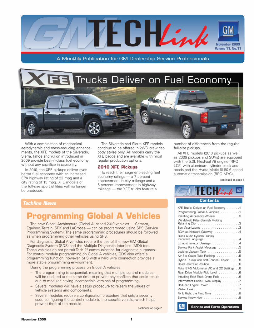
With a combination of mechanical,aerodynamic and mass-reducing enhance-ments, the XFE models of the Silverado,Sierra, Tahoe and Yukon introduced in2009 provide best-in-class fuel economywithout any sacrifice in capability.
In 2010, the XFE pickups deliver evenbetter fuel economy with an increasedEPA highway rating of 22 mpg and acity rating of 15 mpg. XFE models ofthe full-size sport utilities will no longerbe produced.
The Silverado and Sierra XFE modelscontinue to be offered in 2WD crew cabbody styles only. All models carry theXFE badge and are available with mostregular production options.
2010 XFE PickupsTo reach their segment-leading fuel
economy ratings — a 7 percent improvement in city mileage and a 5 percent improvement in highwaymileage — the XFE trucks feature a
number of differences from the regularfull-size pickups.
All XFE models (2010 pickups as wellas 2009 pickups and SUVs) are equippedwith the 5.3L FlexFuel V8 engine (RPOLC9) with aluminum cylinder block andheads and the Hydra-Matic 6L80 6 speedautomatic transmission (RPO MYC).
Techline News
Programming Global A VehiclesThe new Global Architecture (Global A)-based 2010 vehicles — Camaro,
Equinox, Terrain, SRX and LaCrosse — can be programmed using SPS (ServiceProgramming System). The same programming procedures should be followedas when programming other vehicles using SPS.
For diagnosis, Global A vehicles require the use of the new GM GlobalDiagnostic System (GDS) and the Multiple Diagnostic Interface (MDI) tool.These vehicles do not permit Tech 2® communication for diagnostic purposes.For control module programming on Global A vehicles, GDS also offers a programming function, however, SPS with a hard wire connection provides amore stable programming environment.
During the programming process on Global A vehicles:– The programming is sequential, meaning that multiple control modules
will be updated at the same time to prevent any conflicts that could resultdue to modules having incompatible versions of programming.
– Several modules will have a setup procedure to relearn the values of vehicle systems and components.
– Several modules require a configuration procedure that sets a securitycode configuring the control module to the specific vehicle, which helpsprevent theft of the module.
continued on page 2
November 2009Volume 11, No.11
Contents
Service and Parts Operations
continued on page 2
XFE Trucks Deliver on Fuel Economy . . . . . . .1Programming Global A Vehicles . . . . . . . . . .1Installing Accessory Wheels . . . . . . . . . . . .3Windshield Pillar Garnish Molding Retaining Clip . . . . . . . . . . . . . . . . . . . . . .3Sun Visor Labels . . . . . . . . . . . . . . . . . . . .3BCM as Network Gateway . . . . . . . . . . . . . .4Blank Audio System Display, Incorrect Language . . . . . . . . . . . . . . . . . .4Exhaust Isolator Damage . . . . . . . . . . . . . . .4Service Park Assist Message . . . . . . . . . . .5Leaking Vacuum Tank . . . . . . . . . . . . . . . . .5Air Box Outlet Tube Flashing . . . . . . . . . . . .5Hybrid Trucks with Soft Tonneau Cover . . . . .5Head Restraint Position . . . . . . . . . . . . . . .6Fluke 87-5 Multimeter AC and DC Settings . .6Rear Drive Module Fluid Level . . . . . . . . . . .6Installing Roof Rack Cross Rails . . . . . . . . . .6Intermittent Radio/HVAC Display . . . . . . . . .7Reduced Engine Power . . . . . . . . . . . . . . . .7Water Leak . . . . . . . . . . . . . . . . . . . . . . . .7Fix It Right the First Time . . . . . . . . . . . . . .8Service Know How . . . . . . . . . . . . . . . . . . .8
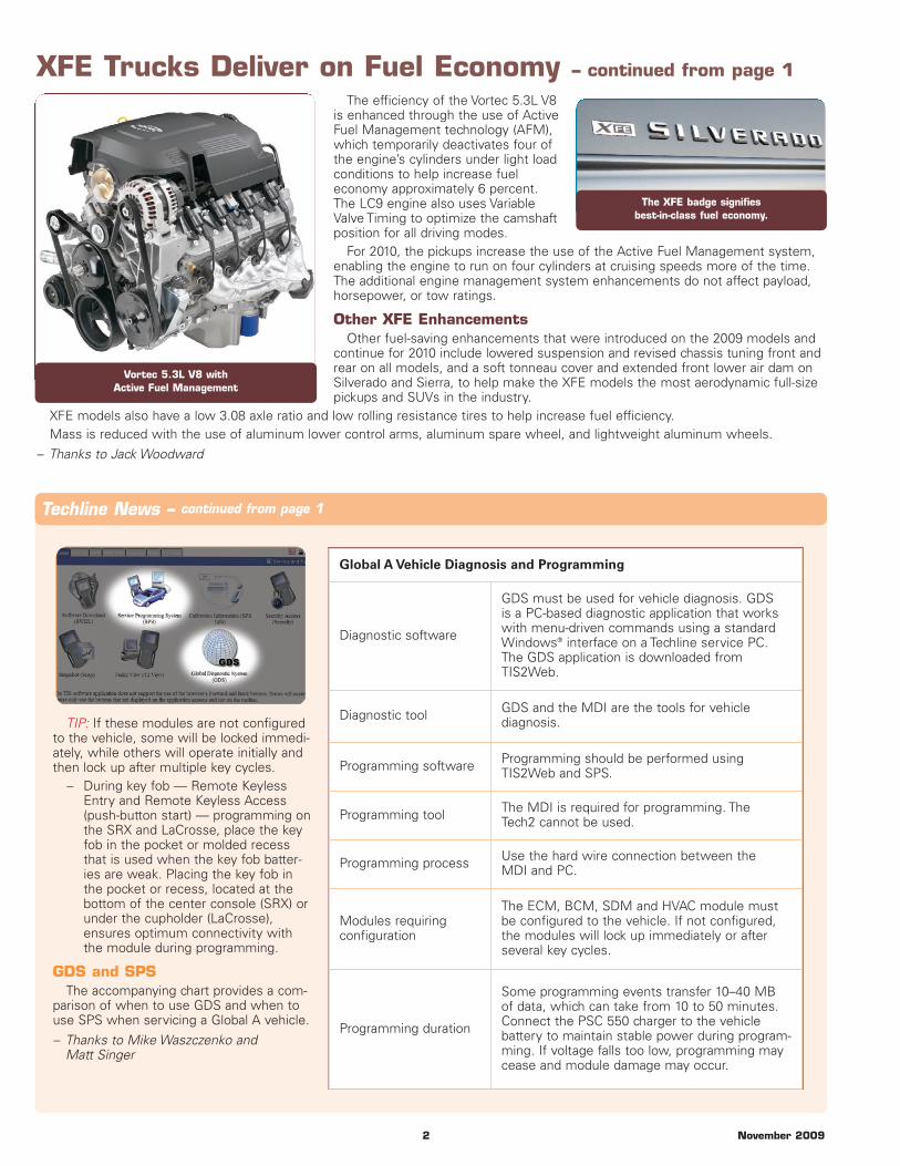
The efficiency of the Vortec 5.3L V8is enhanced through the use of ActiveFuel Management technology (AFM),which temporarily deactivates four ofthe engine’s cylinders under light loadconditions to help increase fueleconomy approximately 6 percent.The LC9 engine also uses VariableValve Timing to optimize the camshaftposition for all driving modes.
For 2010, the pickups increase the use of the Active Fuel Management system,enabling the engine to run on four cylinders at cruising speeds more of the time.The additional engine management system enhancements do not affect payload,horsepower, or tow ratings.
Other XFE EnhancementsOther fuel-saving enhancements that were introduced on the 2009 models and
continue for 2010 include lowered suspension and revised chassis tuning front andrear on all models, and a soft tonneau cover and extended front lower air dam onSilverado and Sierra, to help make the XFE models the most aerodynamic full-sizepickups and SUVs in the industry.
XFE models also have a low 3.08 axle ratio and low rolling resistance tires to help increase fuel efficiency.Mass is reduced with the use of aluminum lower control arms, aluminum spare wheel, and lightweight aluminum wheels.
– Thanks to Jack Woodward
2 November 2009
TIP: If these modules are not configuredto the vehicle, some will be locked immedi-ately, while others will operate initially andthen lock up after multiple key cycles.
– During key fob — Remote KeylessEntry and Remote Keyless Access(push-button start) — programming onthe SRX and LaCrosse, place the keyfob in the pocket or molded recessthat is used when the key fob batter-ies are weak. Placing the key fob inthe pocket or recess, located at thebottom of the center console (SRX) orunder the cupholder (LaCrosse),ensures optimum connectivity withthe module during programming.
GDS and SPSThe accompanying chart provides a com-
parison of when to use GDS and when touse SPS when servicing a Global A vehicle.
– Thanks to Mike Waszczenko and Matt Singer
Techline News – continued from page 1
The XFE badge signifies best-in-class fuel economy.
Vortec 5.3L V8 with Active Fuel Management
XFE Trucks Deliver on Fuel Economy – continued from page 1
Global A Vehicle Diagnosis and Programming
Diagnostic software
GDS must be used for vehicle diagnosis. GDSis a PC-based diagnostic application that workswith menu-driven commands using a standardWindows® interface on a Techline service PC.The GDS application is downloaded fromTIS2Web.
Diagnostic tool GDS and the MDI are the tools for vehicle diagnosis.
Programming software Programming should be performed usingTIS2Web and SPS.
Programming tool The MDI is required for programming. TheTech2 cannot be used.
Programming process Use the hard wire connection between theMDI and PC.
Modules requiring configuration
The ECM, BCM, SDM and HVAC module mustbe configured to the vehicle. If not configured,the modules will lock up immediately or afterseveral key cycles.
Programming duration
Some programming events transfer 10–40 MBof data, which can take from 10 to 50 minutes.Connect the PSC 550 charger to the vehicle battery to maintain stable power during program-ming. If voltage falls too low, programming maycease and module damage may occur.
November 2009 3
Installing Accessory WheelsTechnicians that install LPO dealer-
installed 20- or 22-inch accessorywheels on a full-size utility or pickupmust perform several proceduresin order for all vehicle systems tooperate properly.
Following is a summary of thesteps required when installing the20- or 22-inch accessory wheels oncertain 2009 Escalade, Escalade ESV,Escalade EXT, Avalanche, Silverado,Suburban and Tahoe (1500 series only), Sierra, Yukon, YukonDenali, Yukon XL and Yukon Denali XL (1500 series only) models.
The RPO codes for the 20- or 22-inch accessory wheels thatcan be dealer-installed are: VSA, VSB, VSC, VSF, VS3, VZJ, VZK,VS5, VS4, VSJ, VSK, VZH, VSN and VS8.
RPO RPP designates the 17-inch wheel and tire that will beremoved by the technician.
Vehicles built with RPO RPP always require the following service procedures:
1. Install the new LPO accessory tire/wheel assemblieson the vehicle.
2. Reprogram the control modules for the new tire/wheelsize (steps 2.1, 2.2 and 2.3 must be completed in order).
2.1. Contact TCSC at 1-800-828-6860 (English) or 1-800-503-3222 (French) to set-up the calibration database for the new tire size.
2.2. Reprogram the EBCM (Electronic Brake Control Module).Use Tech 2® pass-through programming in the ServiceProgramming System (SPS).
2.3. Reprogram the ECM (Engine Control Module). UseTech 2® pass-through programming in the ServiceProgramming System (SPS).
3. Reset the tire type and pressure.3.1. Use the Tech 2® to perform a module set-up for the
RCDLR (Remote Control Door Lock Receiver); go toTire Type/Pressure Selection.
3.2. Select the correct tire type (P-metric), and select thenew tire pressure based on the new tire placardincluded with the accessory wheels.
4. Learn the new Tire Pressure Monitor (TPM) sensors tothe vehicle.
5. Install the new tire placard included with the accessorywheels.
6. Set the inflation pressure of each tire according to thenew placard value.
For additional information about this process, please refer toBulletin #06-03-10-001F (SUV) or #06-03-10-011E (Pickup).
GM accessory wheels are validated and released for specific vehicle applications. Warranty coverage and dealerindemnification will not be provided in situations relating toincorrect application usage or failure to perform requiredservice procedures.
– Thanks to Loren Rusk
Windshield Pillar GarnishMolding Retaining Clip
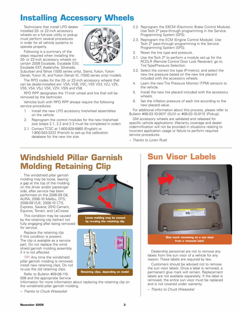
The windshield pillar garnishmolding may be loose, leavinga gap at the top of the moldingon the driver and/or passengerside, after service has been performed on the 2006-09 G6,AURA; 2006-10 Malibu, DTS;2008-09 VUE; 2008-10 CTS,Express, Savana; 2010 Camaro,Equinox, Terrain, and LaCrosse.
This condition may be causedby the retaining clip (tether) notfully engaging after being removedfor service.
Replace the retaining clipif this condition is present.The clip is available as a servicepart. Do not replace the wind-shield garnish molding assemblyif it is not affected.
TIP: Any time the windshieldpillar garnish molding is removed,install new retaining clips. Do notre-use the old retaining clips.
Refer to Bulletin #09-08-110-008 and the appropriate ServiceInformation for more information about replacing the retaining clip onthe windshield pillar garnish molding.
– Thanks to Chuck Wieseckel
Retaining clips, depending on model
Loose molding may be caused by re-using the retaining clip.
Sun Visor Labels
Dealership personnel are not to remove anylabels from the sun visor of a vehicle for any reason. These labels are required by law.
Customers should be advised not to removethe sun visor labels. Once a label is removed, apermanent glue mark will remain. Replacementlabels are not available separately. If the label isremoved, the entire sun visor must be replacedand is not covered under warranty.
– Thanks to Chuck Wieseckel
Glue mark remaining on a sun visor from a removed label.
4 November 2009
BCM asNetworkGateway
This information applies to thefollowing vehicles:
– 2006-2010 HHR– 2005-2010 Cobalt– 2004-2010 Malibu– 2008 Malibu Classic– 2007-2009 AURA– 2005-2009 G6– 2006-2009 Solstice– 2007-2009 SKYMany electrical functions on
these vehicles do not directlyinvolve the Body Control Module(BCM), even though they may onother vehicles. The cooling fans,for example, are controlled bythe ECM on the Malibu, butare controlled by the BCM on theImpala. The BCM is only a gate-way between the high- and low-speed GMLAN serial data buseson the above listed vehicles.
Functions That Do NotInvolve the BCM
The following list of featuresand functions are not controlledor dependent on the BCM. TheBCM should NOT be replaced forconditions in these areas:
– Cooling fans– Clock display– Radio display– Power mirrors– OnStar– Rear wiper (on
Malibu Maxx)– Warning lamps
(Telltale lights)– MIL (Service Engine
Soon light)– Driver seat belt reminder
light and chime– Power windowsTIP: The BCM also acts as a
power distribution center andmay provide a fused battery feedto the modules that actually docontrol these functions.
Do not assume a similar control module issue will applyto different vehicle lines. Referto the appropriate ServiceInformation for the proper diagnostic information.
– Thanks to Alexander Balliosand Marty Case
Exhaust Isolator Damage
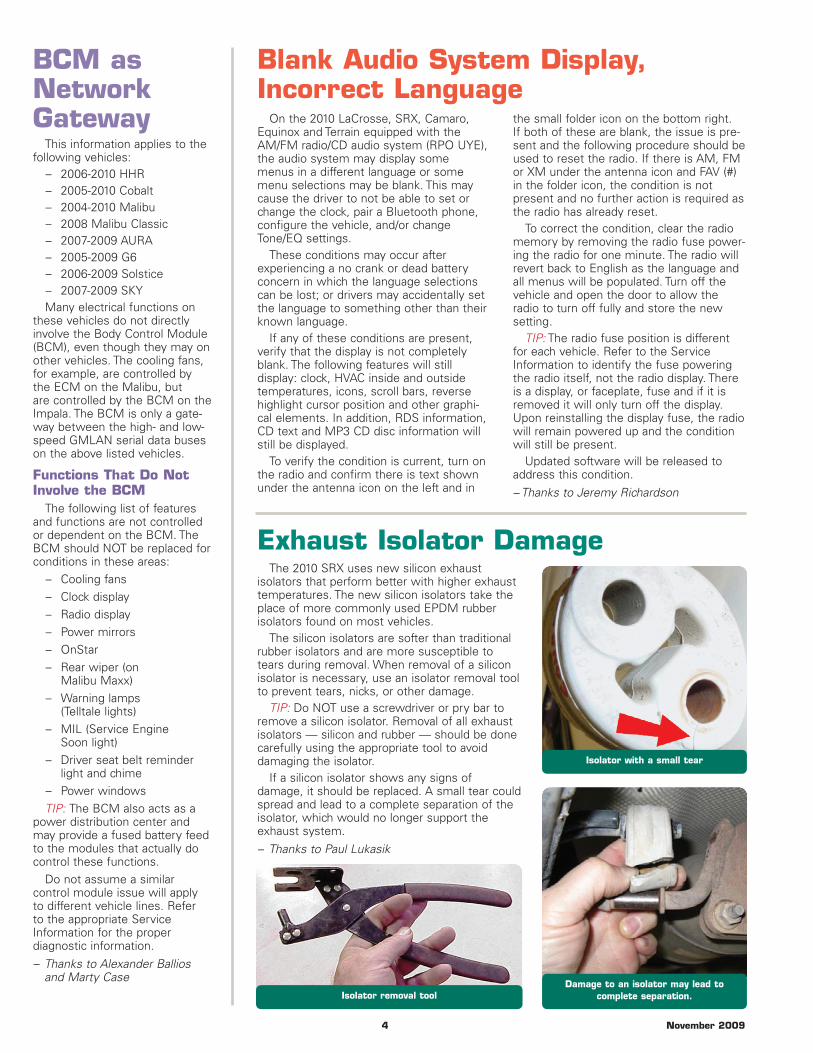
Isolator with a small tear
Isolator removal toolDamage to an isolator may lead to
complete separation.
Blank Audio System Display,Incorrect Language
On the 2010 LaCrosse, SRX, Camaro,Equinox and Terrain equipped with theAM/FM radio/CD audio system (RPO UYE),the audio system may display somemenus in a different language or somemenu selections may be blank. This maycause the driver to not be able to set orchange the clock, pair a Bluetooth phone,configure the vehicle, and/or changeTone/EQ settings.
These conditions may occur after experiencing a no crank or dead batteryconcern in which the language selectionscan be lost; or drivers may accidentally setthe language to something other than theirknown language.
If any of these conditions are present,verify that the display is not completelyblank. The following features will still display: clock, HVAC inside and outsidetemperatures, icons, scroll bars, reversehighlight cursor position and other graphi-cal elements. In addition, RDS information,CD text and MP3 CD disc information willstill be displayed.
To verify the condition is current, turn onthe radio and confirm there is text shownunder the antenna icon on the left and in
the small folder icon on the bottom right.If both of these are blank, the issue is pre-sent and the following procedure should beused to reset the radio. If there is AM, FMor XM under the antenna icon and FAV (#)in the folder icon, the condition is not present and no further action is required asthe radio has already reset.
To correct the condition, clear the radiomemory by removing the radio fuse power-ing the radio for one minute. The radio willrevert back to English as the language andall menus will be populated. Turn off thevehicle and open the door to allow theradio to turn off fully and store the newsetting.
TIP: The radio fuse position is differentfor each vehicle. Refer to the ServiceInformation to identify the fuse poweringthe radio itself, not the radio display. Thereis a display, or faceplate, fuse and if it isremoved it will only turn off the display.Upon reinstalling the display fuse, the radiowill remain powered up and the conditionwill still be present.
Updated software will be released toaddress this condition.
– Thanks to Jeremy Richardson
The 2010 SRX uses new silicon exhaust isolators that perform better with higher exhausttemperatures. The new silicon isolators take theplace of more commonly used EPDM rubber isolators found on most vehicles.
The silicon isolators are softer than traditional rubber isolators and are more susceptible totears during removal. When removal of a silicon isolator is necessary, use an isolator removal toolto prevent tears, nicks, or other damage.
TIP: Do NOT use a screwdriver or pry bar toremove a silicon isolator. Removal of all exhaust isolators — silicon and rubber — should be donecarefully using the appropriate tool to avoid damaging the isolator.
If a silicon isolator shows any signs of damage, it should be replaced. A small tear couldspread and lead to a complete separation of theisolator, which would no longer support theexhaust system.
– Thanks to Paul Lukasik
November 2009 5
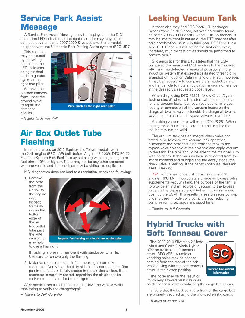
Service Park AssistMessage
A Service Park Assist Message may be displayed on the DICand/or the LED indicators at the right rear pillar may stay on orbe inoperative on some 2007-2009 Silverado and Sierra modelsequipped with the Ultrasonic Rear Parking Assist system (RPO UD7).
This conditionmay be causedby the wiringharness to theLED indicatorsbeing pinchedunder a groundeyelet at theright rear pillar.
Remove thepinched harnessfrom under theground eyeletto repair thedamaged circuits.
– Thanks to James Will
Wire pinch at the right rear pillar
Leaking Vacuum TankA technician may find DTC P2261, Turbocharger
Bypass Valve Stuck Closed, set with no trouble foundon some 2008-2009 Cobalt SS and HHR SS models. Itmay be intermittent in nature or the DTC may set afterhard acceleration, usually in third gear. DTC P2261 is aType B DTC and will not set on the first drive cycle,therefore, multiple test drives should be performed toconfirm repair.
SI diagnostics for this DTC states that the ECM compared the measured MAF reading to the modeledMAF and has detected a series of pulsations in theinduction system that exceed a calibrated threshold. Asnapshot of Induction Data will show the fault, however,it may be necessary to compare the snapshot data toanother vehicle to note a fluctuation and/or a differencein the desired vs. requested boost level.
When diagnosing DTC P2261, follow Circuit/SystemTesting step #1 closely. This step calls for inspectingfor any vacuum leaks, damage, restrictions, improperrouting or connection of the vacuum hoses on thecharge air bypass valve solenoid, the charge air bypassvalve, and the charge air bypass valve vacuum tank.
A leaking vacuum tank will cause DTC P2261. Whentesting the vacuum tank, care must be used or theresults may not be valid.
The vacuum tank has an integral check valve notnoted in SI. To check the vacuum tank operation, disconnect the hose that runs from the tank to thebypass valve solenoid at the solenoid and apply vacuumto the tank. The tank should be able to maintain vacuumwith no decay. If the vacuum hose is removed from theintake manifold and plugged and the decay stops, thecheck valve is leaking. If the decay continues, the tankitself is leaking.
TIP: Front wheel drive platforms using the 2.0Lengine (RPO LNF) incorporate a charge air bypass valvesupplemental vacuum tank. The purpose of the tank isto provide an instant source of vacuum to the bypassvalve via the bypass solenoid (when it is commandedopen by the ECM). This results in less pressure buildupunder closed throttle conditions, thereby reducing compressor noise, surge and spool time.
– Thanks to Jeff Gorenflo
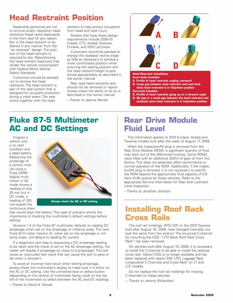
Air Box Outlet TubeFlashing
In rare instances on 2010 Equinox and Terrain models withthe 2.4L engine (RPO LAF) built before August 17, 2009, DTC P0172,Fuel Trim System Rich Bank 1, may set along with a high long-termfuel trim (–19% or higher). There may not be any other concernswith the vehicle and the condition may be difficult to duplicate.
If SI diagnostics does not lead to a resolution, check the following:
1. Removethe hosefrom theair box tothe engineinlet.Inspectfor flash-ing on thebottomedge ofthe airbox outlettube pastthe MAFsensor. Itmay helpto use a flashlight.
If flashing is present, remove it with sandpaper or a file.Use care to remove only the flashing.
2. Make sure the complete air filter housing is correctly assembled. Verify that the dirty side air cleaner resonator (thepart in the fender), is fully seated in the air cleaner box. If the resonator is not fully seated, reposition the air cleaner boxand/or the resonator for better alignment.
After service, reset fuel trims and test drive the vehicle whilemonitoring to verify the change/repair.
– Thanks to Jeff Gorenflo
Hybrid Trucks withSoft Tonneau Cover
The 2009-2010 Silverado 2-ModeHybrid and Sierra 2-Mode Hybridoffer an available soft tonneaucover (RPO VPB). A rattle or knocking noise may be noticedcoming from the rear of the cabwhile driving with the soft tonneaucover in the closed position.
The noise may be the result ofimproperly stowed plastic buckleson the tonneau cover contacting the cargo box or cab.
Ensure that the buckles at the front of the cargo boxare properly secured using the provided elastic cords.
– Thanks to James Will
Service ConsultantInformation
Inspect for flashing on the air box outlet tube.
6 November 2009
Head Restraint Position
Fluke 87-5 MultimeterAC and DC Settings
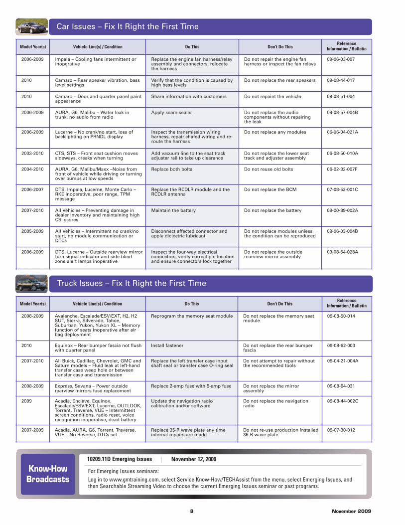
Imagine avehicle witha no start condition anda dead battery.Measuring theamperage ofa control mod-ule using aFluke DMM(digital multi-meter) in ACmode shows areading of only25 ma, but inDC mode, areading of 335ma reveals thecontinuous drawthat would drain the battery. This type of scenario shows theimportance of checking the multimeter’s default settings beforetesting.
Versions 1-4 of the Fluke 87 multimeter defaults to reading DCamperage when set on the amperage or milliamp scale. The newFluke 87-5 meter (version 5), when set on the amperage or mil-liamp scale, will default to reading AC current.
If a diagnostic test step is requesting a DC amperage readingto be taken and the meter is set on the AC amperage setting, themeter will display 0 amperage (or close to 0 amperage). This willcause an inaccurate test result that can cause the test to pass orfail when it shouldn’t.
To avoid an incorrect test result when testing amperage,always check the multimeter’s display to make sure it is either onthe AC or DC setting. Use the unmarked blue or yellow button(depending on the version of multimeter being used) on the topleft of the multimeter to select between the AC and DC readings.
– Thanks to David N. Nowak
Rear Drive ModuleFluid Level
This information applies to 2010 Enclave, Acadia andTraverse models built after the week of August 17, 2009.
When the inspection/fill plug is removed from theRear Drive Module (RDM), a significant quantity of fluidmay drain out of the differential housing. Some RDMswere filled with an additional 200ml of gear oil from thefactory. This does not adversely affect performance or normal operation of the RDM. Additionally, if the inspec-tion/fill plug is removed, it is not necessary to over-fillthe RDM beyond the approximate fluid capacity of 0.8liters (0.85 quarts) for these vehicles. Refer to the appropriate Service Information for Rear Axle LubricantLevel Inspection.
– Thanks to Jonathan Johnson
Always check the AC or DC setting
Installing Roof RackCross Rails
The roof rail moldings, RPO V2P, on the 2010 Traversebuilt after August 16, 2009, have changed internally, butlook the same from the exterior. The structural C-channelfor mounting the VQQ ”LPO Black Roof Rack CrossRails“ has been removed.
On vehicles built after August 16, 2009, it is necessaryto install the C-channel to be able to install the optionalcross rails. Option VQQ is no longer available and hasbeen replaced with option S49 "LPO Luggage RackLongitudinal C-Channels and Cross Rails" on LT andLTZ models.
Do not replace the roof rail moldings for missing C-channels on these vehicles.
– Thanks to Jeremy Richardson
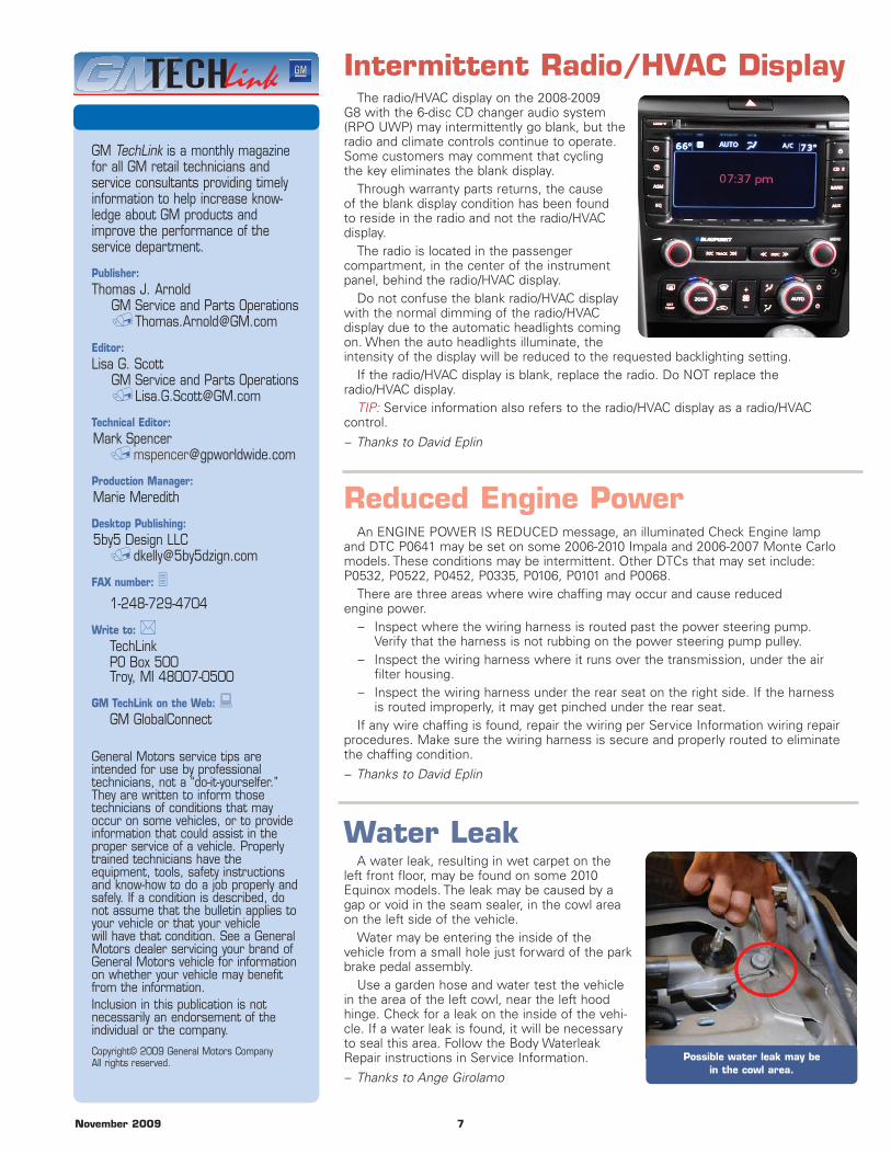
Dealership personnel are notto remove and/or reposition headrestraints (head rests) backwardsin the front seat for any reason.Nor is the head restraint to bealtered in any manner from the“as received” design. The posi-tion of the head restraint isrequired by law. Repositioningthe head restraint backward mayrender the vehicle noncompliantwith Federal Motor VehicleSafety Standards.
Customers should be advisednot to remove the headrestraints. The head restraint ispart of the seat system that isdesigned for occupant protectionduring a crash event. The seatworks together with the head
Head Restraint InstallationIncorrectly Installed:A. Profile of head restraint angling rearwardB. Large gap between head restraint and seat back
when head restraint is in fully-down positionCorrectly Installed:C. Profile of head restraint going up on a forward angleD. No gap or a small gap between the head restraint and
seatback when head restraint is in fully-down position
restraint to help protect occupantsfrom head and neck injury.
Models that have these designrequirements include 2009-10Impala, CTS, Acadia, Traverse,Enclave, and 2010 LaCrosse.
Customers should be advised tochange the seatback recline angleas little as necessary to achieve amore comfortable position whileensuring the seating position andthe head restraint height is posi-tioned appropriately as described inthe owner manual.
Rear seat head restraints alsoshould not be removed or reposi-tioned unless the ability to do so isdescribed in the owner manual.
– Thanks to Jeanne Barrett
November 2009 7
GM TechLink is a monthly magazinefor all GM retail technicians andservice consultants providing timelyinformation to help increase know -ledge about GM products andimprove the performance of theservice department.
Publisher:Thomas J. Arnold
GM Service and Parts Operations/[email protected]
Editor:Lisa G. Scott
GM Service and Parts Operations/[email protected]
Technical Editor:Mark Spencer
Production Manager:Marie Meredith
Desktop Publishing:5by5 Design LLC
FAX number: 31-248-729-4704
Write to: *TechLinkPO Box 500Troy, MI 48007-0500
GM TechLink on the Web: :GM GlobalConnect
General Motors service tips areintended for use by professional technicians, not a “do-it-yourselfer.” T hey are written to inform those technicians of conditions that mayoccur on some vehicles, or to provide information that could assist in theproper service of a vehicle. Properlytrained technicians have theequipment, tools, safety instructionsand know-how to do a job properly andsafely. If a condition is described, donot assume that the bulletin applies toyour vehicle or that your vehiclewill have that condition. See a GeneralMotors dealer servicing your brand ofGeneral Motors vehicle for informationon whether your vehicle may benefitfrom the information.Inclusion in this publication is not necessarily an endorsement of theindividual or the company.
Copyright© 2009 General Motors CompanyAll rights reserved.
Intermittent Radio/HVAC DisplayThe radio/HVAC display on the 2008-2009
G8 with the 6-disc CD changer audio system(RPO UWP) may intermittently go blank, but theradio and climate controls continue to operate.Some customers may comment that cyclingthe key eliminates the blank display.
Through warranty parts returns, the causeof the blank display condition has been foundto reside in the radio and not the radio/HVACdisplay.
The radio is located in the passenger compartment, in the center of the instrumentpanel, behind the radio/HVAC display.
Do not confuse the blank radio/HVAC displaywith the normal dimming of the radio/HVAC display due to the automatic headlights comingon. When the auto headlights illuminate, theintensity of the display will be reduced to the requested backlighting setting.
If the radio/HVAC display is blank, replace the radio. Do NOT replace the radio/HVAC display.
TIP: Service information also refers to the radio/HVAC display as a radio/HVAC control.
– Thanks to David Eplin
An ENGINE POWER IS REDUCED message, an illuminated Check Engine lampand DTC P0641 may be set on some 2006-2010 Impala and 2006-2007 Monte Carlomodels. These conditions may be intermittent. Other DTCs that may set include:P0532, P0522, P0452, P0335, P0106, P0101 and P0068.
There are three areas where wire chaffing may occur and cause reducedengine power.
– Inspect where the wiring harness is routed past the power steering pump.Verify that the harness is not rubbing on the power steering pump pulley.
– Inspect the wiring harness where it runs over the transmission, under the air filter housing.
– Inspect the wiring harness under the rear seat on the right side. If the harnessis routed improperly, it may get pinched under the rear seat.
If any wire chaffing is found, repair the wiring per Service Information wiring repairprocedures. Make sure the wiring harness is secure and properly routed to eliminatethe chaffing condition.
– Thanks to David Eplin
Water LeakA water leak, resulting in wet carpet on the
left front floor, may be found on some 2010Equinox models. The leak may be caused by agap or void in the seam sealer, in the cowl areaon the left side of the vehicle.
Water may be entering the inside of the vehicle from a small hole just forward of the parkbrake pedal assembly.
Use a garden hose and water test the vehiclein the area of the left cowl, near the left hoodhinge. Check for a leak on the inside of the vehi-cle. If a water leak is found, it will be necessaryto seal this area. Follow the Body WaterleakRepair instructions in Service Information.
– Thanks to Ange Girolamo
Possible water leak may be in the cowl area.
Reduced Engine Power
Car Issues – Fix It Right the First Time
Know-HowBroadcasts
10209.11D Emerging Issues
Truck Issues – Fix It Right the First Time
Model Year(s) Vehicle Line(s) / Condition Do This Don’t Do ThisReference
Information / Bulletin
2008-2009 Avalanche, Escalade/ESV/EXT, H2, H2SUT, Sierra, Silverado, Tahoe,Suburban, Yukon, Yukon XL – Memoryfunction of seats inoperative after airbag deployment
Reprogram the memory seat module Do not replace the memory seatmodule
09-08-50-014
2010 Equinox – Rear bumper fascia not flushwith quarter panel
Install fastener Do not replace the rear bumperfascia
09-08-62-003
2007-2010 All Buick, Cadillac, Chevrolet, GMC andSaturn models – Fluid leak at left-handtransfer case weep hole or betweentransfer case and transmission
Replace the left transfer case inputshaft seal or transfer case O-ring seal
Do not attempt to repair withoutthe recommended tools
09-04-21-004A
2008-2009 Express, Savana – Power outsiderearview mirrors fuse replacement
Replace 2-amp fuse with 5-amp fuse Do not replace the mirrorassembly
09-08-64-031
2009 Acadia, Enclave, Equinox,Escalade/ESV/EXT, Lucerne, OUTLOOK,Torrent, Traverse, VUE – Intermittentscreen conditions, radio reset, voicerecognition inoperative, dead battery
Update the navigation radiocalibration and/or software
Do not replace the navigationradio
09-08-44-002C
2007-2009 Acadia, AURA, G6, Torrent, Traverse,VUE – No Reverse, DTCs set
Replace 35-R wave plate any timeinternal repairs are made
Do not re-use production installed 35-R wave plate
09-07-30-012
8 November 2009
Model Year(s) Vehicle Line(s) / Condition Do This Don’t Do ThisReference
Information / Bulletin
2006-2009 Impala – Cooling fans intermittent orinoperative
Replace the engine fan harness/relayassembly and connectors, relocatethe harness
Do not repair the engine fanharness or inspect the fan relays
09-06-03-007
2010 Camaro – Rear speaker vibration, basslevel settings
Verify that the condition is caused byhigh bass levels
Do not replace the rear speakers 09-08-44-017
2010 Camaro – Door and quarter panel paintappearance
Share information with customers Do not repaint the vehicle 09-08-51-004
2006-2009 AURA, G6, Malibu – Water leak intrunk, no audio from radio
Apply seam sealer Do not replace the audiocomponents without repairingthe leak
09-08-57-004B
2006-2009 Lucerne – No crank/no start, loss ofbacklighting on PRNDL display
Inspect the transmission wiringharness, repair chafed wiring and re-route the harness
Do not replace any modules 06-06-04-021A
2003-2010 CTS, STS – Front seat cushion movessideways, creaks when turning
Add vacuum line to the seat trackadjuster rail to take up clearance
Do not replace the lower seattrack and adjuster assembly
06-08-50-010A
2004-2010 AURA, G6, Malibu/Maxx –Noise fromfront of vehicle while driving or turningover bumps at low speeds
Replace both bolts Do not reuse old bolts 06-02-32-007F
2006-2007 DTS, Impala, Lucerne, Monte Carlo –RKE inoperative, poor range, TPMmessage
Replace the RCDLR module and theRCDLR antenna
Do not replace the BCM 07-08-52-001C
2007-2010 All Vehicles – Preventing damage indealer inventory and maintaining highCSi scores
Maintain the battery Do not replace the battery 09-00-89-002A
2005-2009 All Vehicles – Intermittent no crank/nostart, no module communication orDTCs
Disconnect affected connector andapply dielectric lubricant
Do not replace modules unlessthe condition can be reproduced
09-06-03-004B
2006-2009 DTS, Lucerne – Outside rearview mirrorturn signal indicator and side blindzone alert lamps inoperative
Inspect the four-way electricalconnectors, verify correct pin locationand ensure connectors lock together
Do not replace the outsiderearview mirror assembly
09-08-64-028A
For Emerging Issues seminars:Log in to www.gmtraining.com, select Service Know-How/TECHAssist from the menu, select Emerging Issues, andthen Searchable Streaming Video to choose the current Emerging Issues seminar or past programs.
November 12, 2009