Embed Size (px)
Citation preview
PROGRAMMING TECHNIQUES
Chapter 5(Part 2)
©Sheila Belayutham
LEARNING OUTCOMEAt the end of this lesson, students willbe able to:• Understand the different types of
planning techniques.• Understand the network analysis.• Formulate a network diagram.
©Sheila Belayutham
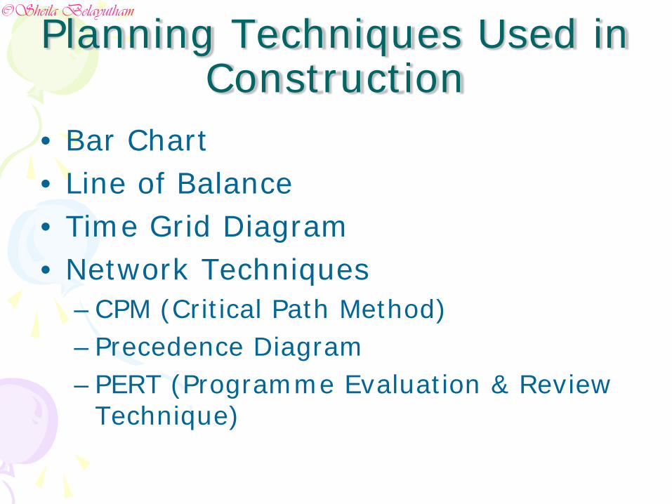
Planning Techniques Used in Construction
• Bar Chart• Line of Balance• Time Grid Diagram• Network Techniques
–CPM (Critical Path Method)–Precedence Diagram–PERT (Programme Evaluation & Review
Technique)
©Sheila Belayutham
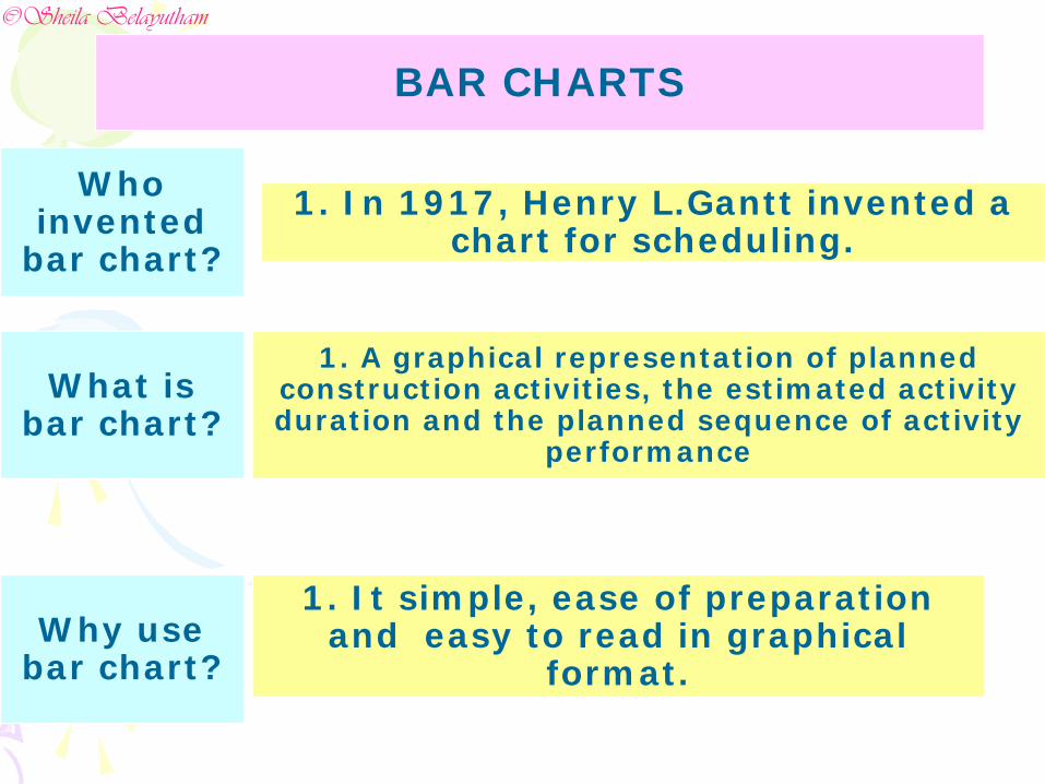
BAR CHARTS
Who invented
bar chart?1. In 1917, Henry L.Gantt invented a
chart for scheduling.
1. It simple, ease of preparation and easy to read in graphical
format.Why use
bar chart?
What is bar chart?
1. A graphical representation of planned construction activities, the estimated activity duration and the planned sequence of activity
performance
©Sheila Belayutham
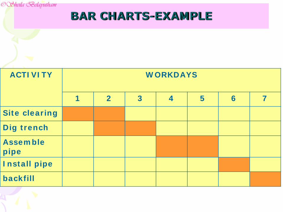
BAR CHARTS-EXAMPLE
ACTIVITY WORKDAYS
1 2 3 4 5 6 7
Site clearing
Dig trench
Assemble pipeInstall pipe
backfill
©Sheila Belayutham
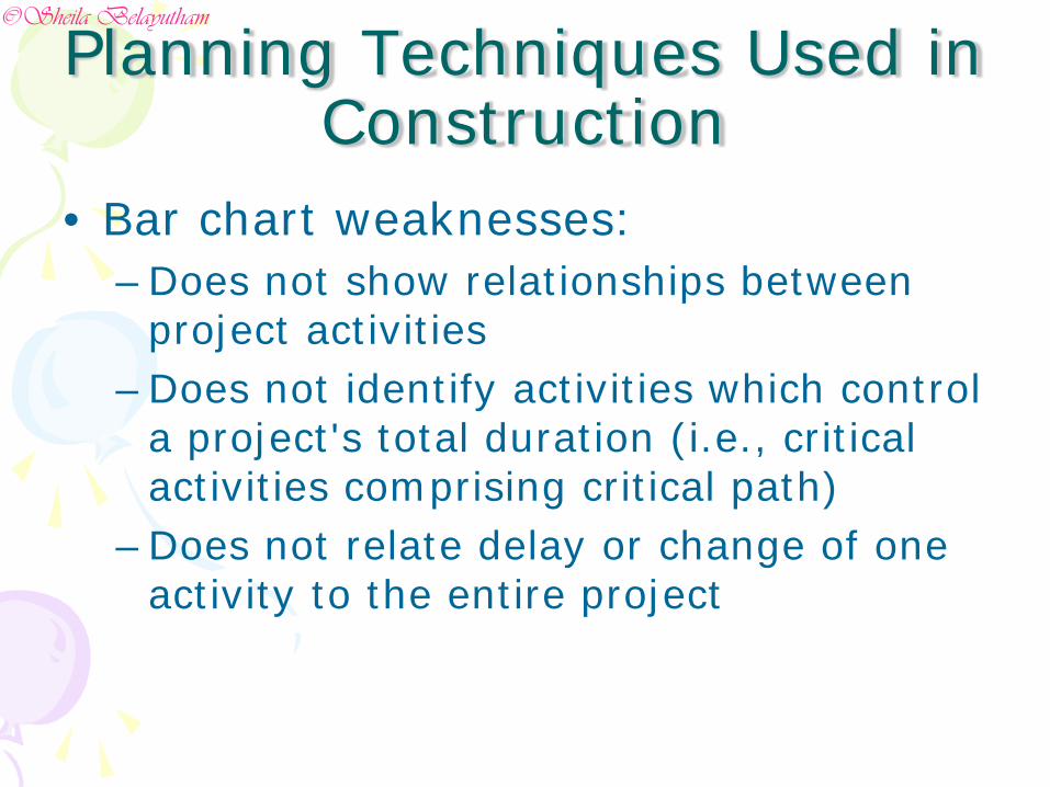
• Bar chart weaknesses: –Does not show relationships between
project activities –Does not identify activities which control
a project's total duration (i.e., critical activities comprising critical path)
–Does not relate delay or change of one activity to the entire project
Planning Techniques Used in Construction
©Sheila Belayutham
• Network planning methods remedy bar chart weaknesses:
– CPM - developed in late 1950s by industry to schedule maintenance & construction work utilizing computers
– PERT - Programme Evaluation & Review Technique -developed in late 1950s by U.S. Navy to support the Polaris missile weapons system acquisition
– CPM & PERT have much in common with PERT being somewhat more sophisticated with the use of probability concepts to deal with uncertain activity durations. CPM uses a single fixed duration for each activity
Planning Techniques Used in Construction
©Sheila Belayutham
Choice of Scheduling Method
• Factors that governed the choice of factors are as follows:– Familiarity on the technique to be used
• Acceptable by parties involved.
– Type and size of project• Project with few but repetitive task-Line of Balance• Med to large project with numerous task-CPM or
Precedence• Small project-Bar chart
– Purpose of scheduling
©Sheila Belayutham
Network Analysis• Net work analysis is a method of
project planning done on activities so that it is connected to each other. This network is used to optimised the usage of resources and also for monitoring and controlling.
• The purpose is to ascertain the critical path for a certain project.
©Sheila Belayutham
• Type of network analysis– CPM– Precedence Diagram– PERT
• Techniques– Activity on arrow (CPM)
• Arrow represents activity• Activities are represented by arrows whereas the
start or end of each activity is represented by a node. • One of the main drawbacks of this technique is the
existence of dummy activities, which might complicate the network and cause some confusion.
Network Analysis
©Sheila Belayutham
–Activity on node (Precedence)• Node represents activity
Network Analysis
©Sheila Belayutham
Steps in building a network model
• Define activities• Order activities• Draw a network diagram• Assign durations to activities• Assign resources and cost• Calculate early and late start/ finish
times.• Schedule activity start/ finish times.
©Sheila Belayutham
Project Task or Activity• An activity or task is a single work
step that has a recognisable beginning and end and requires time and resources for its accomplishment.
©Sheila Belayutham
Logical Relationship of Project Activities
• Very important for a planner to understand the order of how the job to be accomplished in the filed.
• Should understand how various activities of the project related to each other in term of their logical sequence.
©Sheila Belayutham
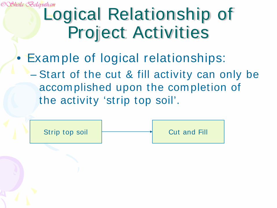
• Example of logical relationships:–Start of the cut & fill activity can only be
accomplished upon the completion of the activity ‘strip top soil’.
Logical Relationship of Project Activities
Strip top soil Cut and Fill
©Sheila Belayutham
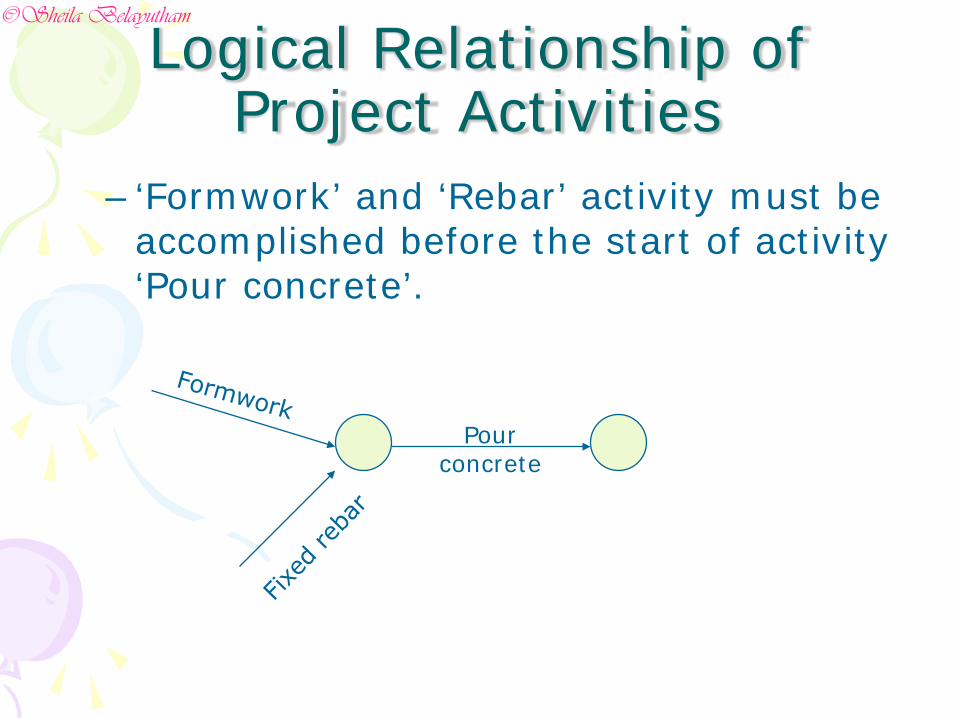
– ‘Formwork’ and ‘Rebar’ activity must be accomplished before the start of activity ‘Pour concrete’.
Pour concrete
Logical Relationship of Project Activities
©Sheila Belayutham
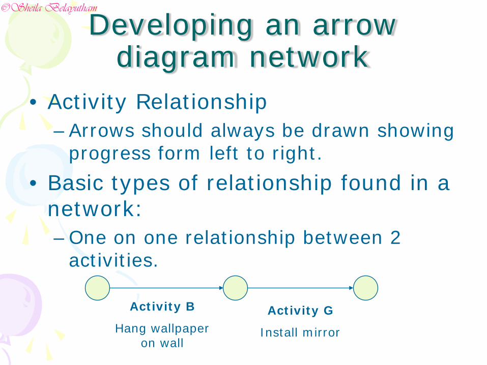
Developing an arrow diagram network
• Activity Relationship–Arrows should always be drawn showing
progress form left to right.• Basic types of relationship found in a
network:–One on one relationship between 2
activities.
Activity B
Hang wallpaper on wall
Activity G
Install mirror
©Sheila Belayutham
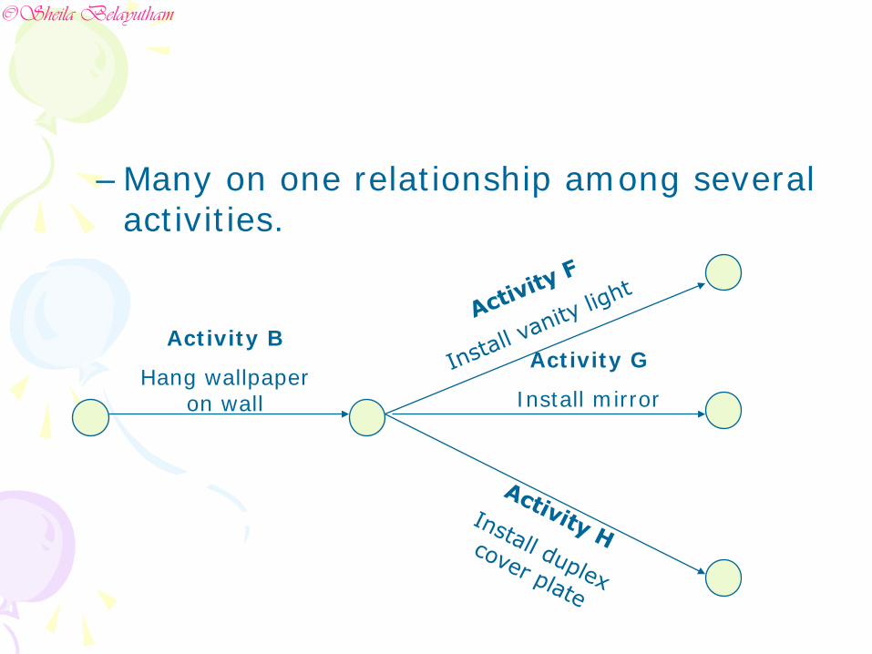
–Many on one relationship among several activities.
Activity B
Hang wallpaper on wall
Activity G
Install mirror
©Sheila Belayutham
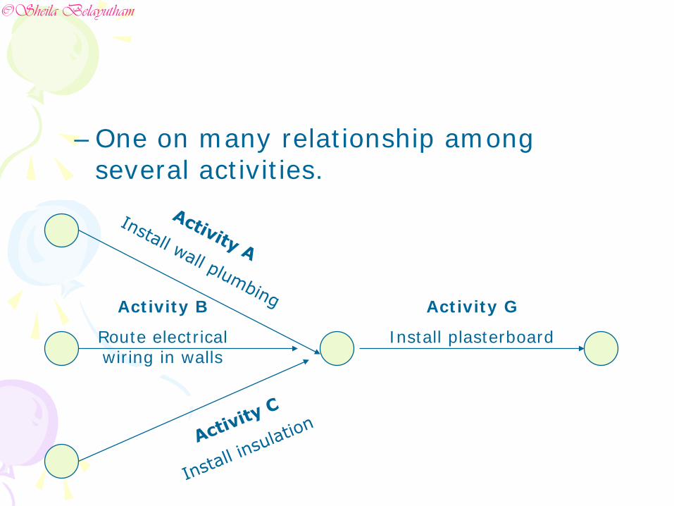
–One on many relationship among several activities.
Activity G
Install plasterboard
Activity B
Route electrical wiring in walls
©Sheila Belayutham
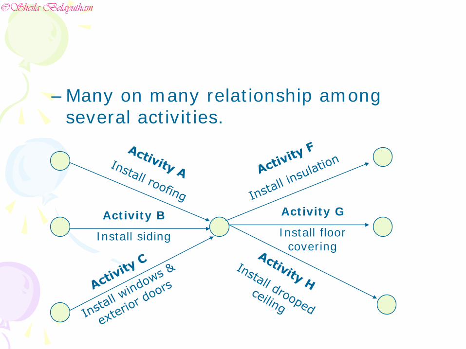
–Many on many relationship among several activities.
Activity B
Install siding
Activity G
Install floor covering
©Sheila Belayutham
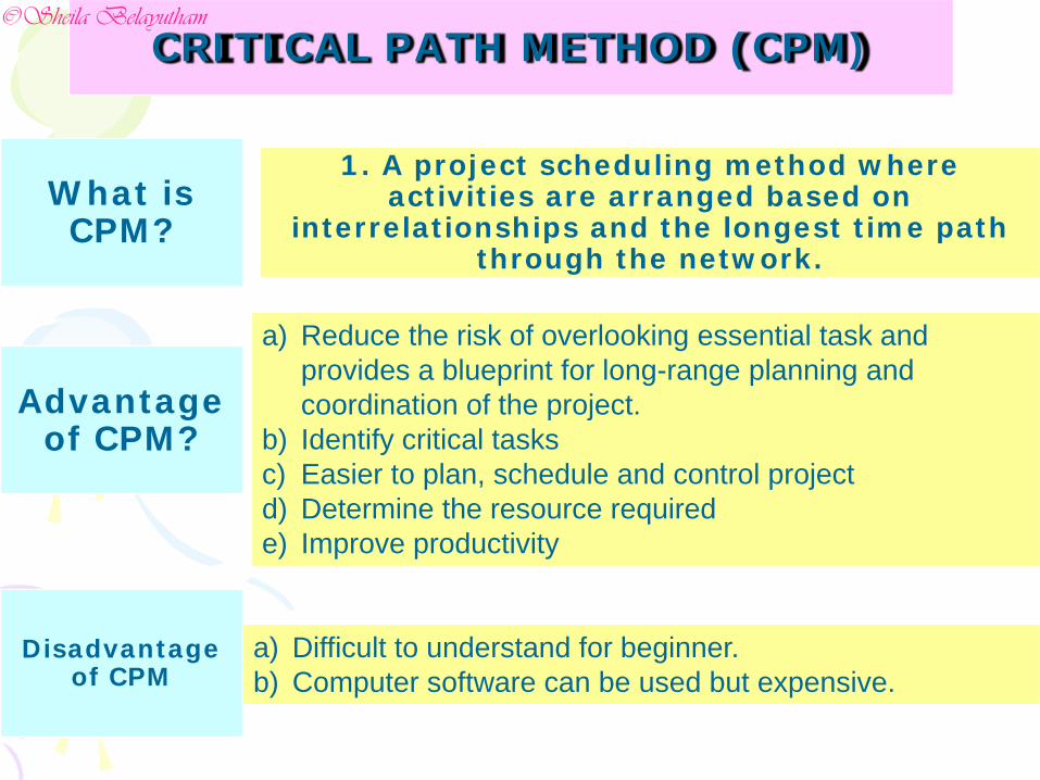
CRITICAL PATH METHOD (CPM)
What is CPM?
1. A project scheduling method where activities are arranged based on
interrelationships and the longest time path through the network.
Disadvantage of CPM
Advantage of CPM?
a) Reduce the risk of overlooking essential task and provides a blueprint for long-range planning and coordination of the project.
b) Identify critical tasksc) Easier to plan, schedule and control projectd) Determine the resource requirede) Improve productivity
a) Difficult to understand for beginner.b) Computer software can be used but expensive.
©Sheila Belayutham
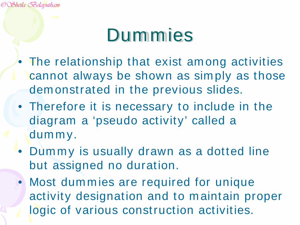
Dummies• The relationship that exist among activities
cannot always be shown as simply as those demonstrated in the previous slides.
• Therefore it is necessary to include in the diagram a ‘pseudo activity’ called a dummy.
• Dummy is usually drawn as a dotted line but assigned no duration.
• Most dummies are required for unique activity designation and to maintain proper logic of various construction activities.
©Sheila Belayutham
For Example:• Activity A-Place concrete slab in garage• Activity B-Install garage door• Activity C-Install pre finished shop
cabinets• Activity D-Install garage door opener
©Sheila Belayutham
20 2510
15 30
A
B
C
D
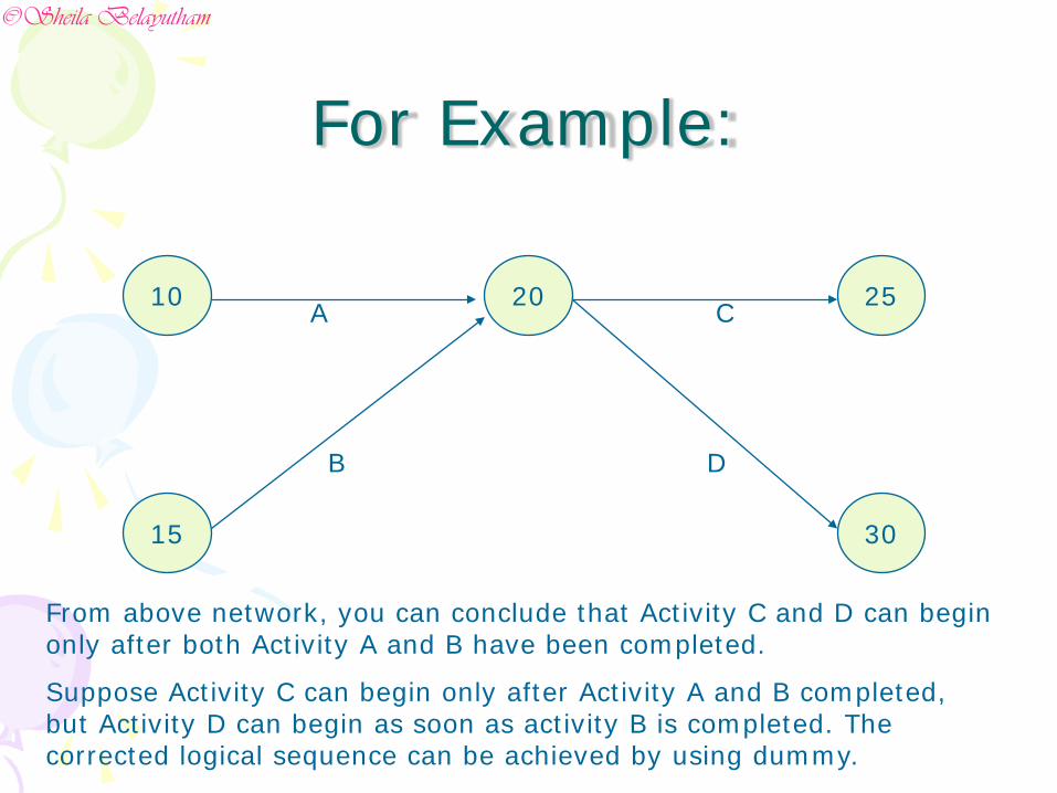
From above network, you can conclude that Activity C and D can begin only after both Activity A and B have been completed.
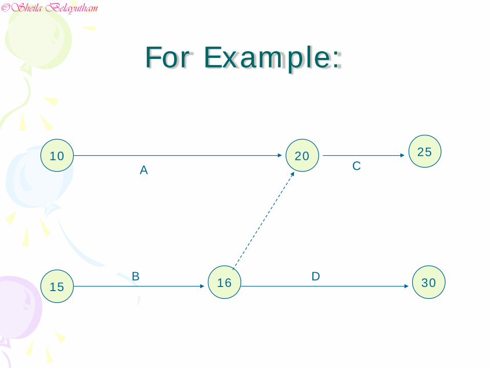
Suppose Activity C can begin only after Activity A and B completed, but Activity D can begin as soon as activity B is completed. The corrected logical sequence can be achieved by using dummy.
For Example:
©Sheila Belayutham
10
15
20 25
3016
A
B D
C
For Example:
©Sheila Belayutham
Formulating a Network Diagram
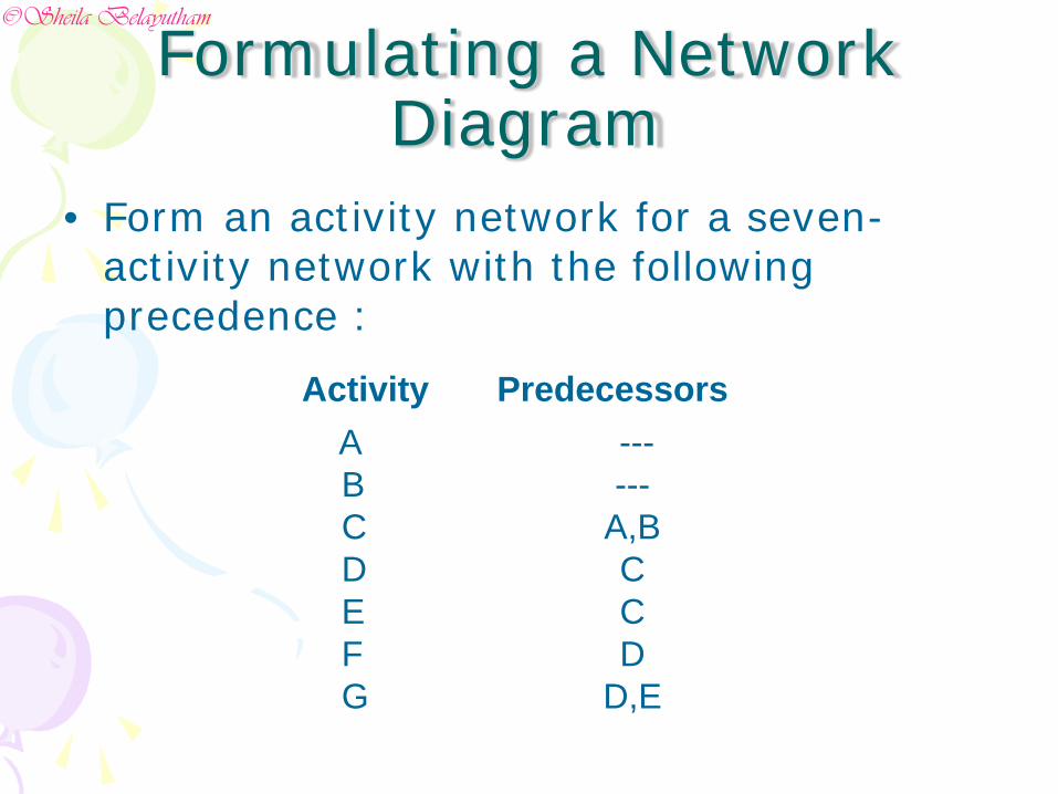
• Form an activity network for a seven-activity network with the following precedence :
Activity PredecessorsABCDEFG
------
A,BCCD
D,E
©Sheila Belayutham
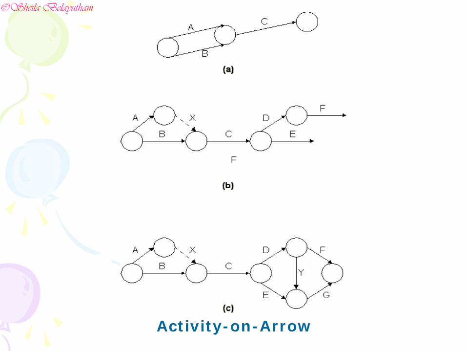
Activity-on-Arrow
©Sheila Belayutham
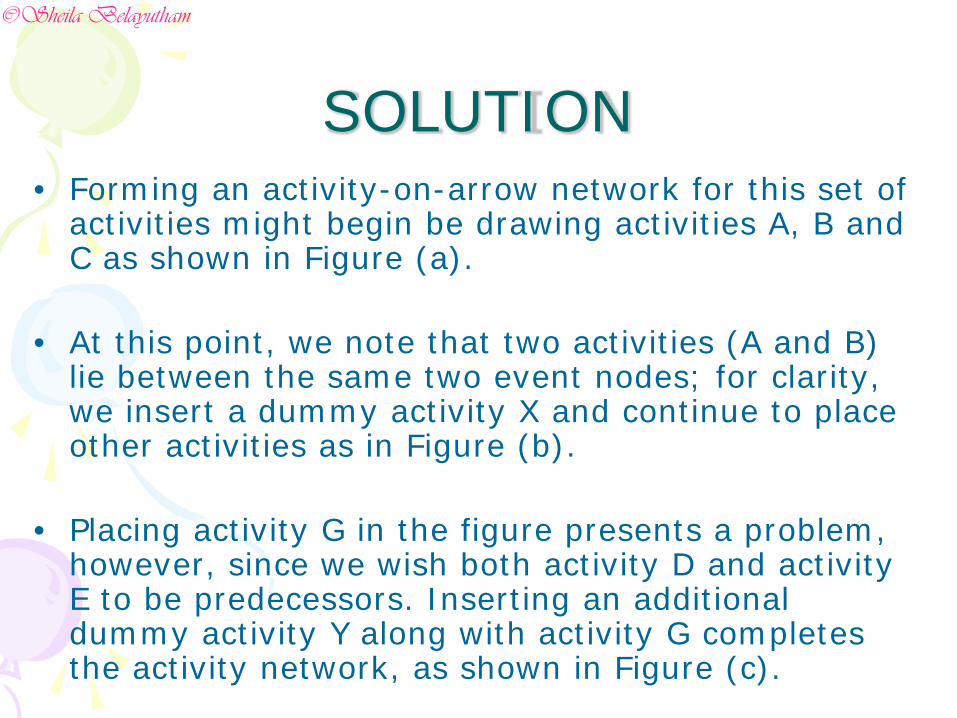
SOLUTION• Forming an activity-on-arrow network for this set of
activities might begin be drawing activities A, B and C as shown in Figure (a).
• At this point, we note that two activities (A and B) lie between the same two event nodes; for clarity, we insert a dummy activity X and continue to place other activities as in Figure (b).
• Placing activity G in the figure presents a problem, however, since we wish both activity D and activity E to be predecessors. Inserting an additional dummy activity Y along with activity G completes the activity network, as shown in Figure (c).
©Sheila Belayutham
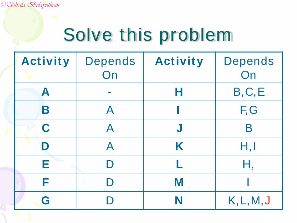
Solve this problemActivity Depends
OnActivity Depends
OnA - H B,C,EB A I F,GC A J BD A K H,IE D L H,F D M IG D N K,L,M,J
©Sheila Belayutham
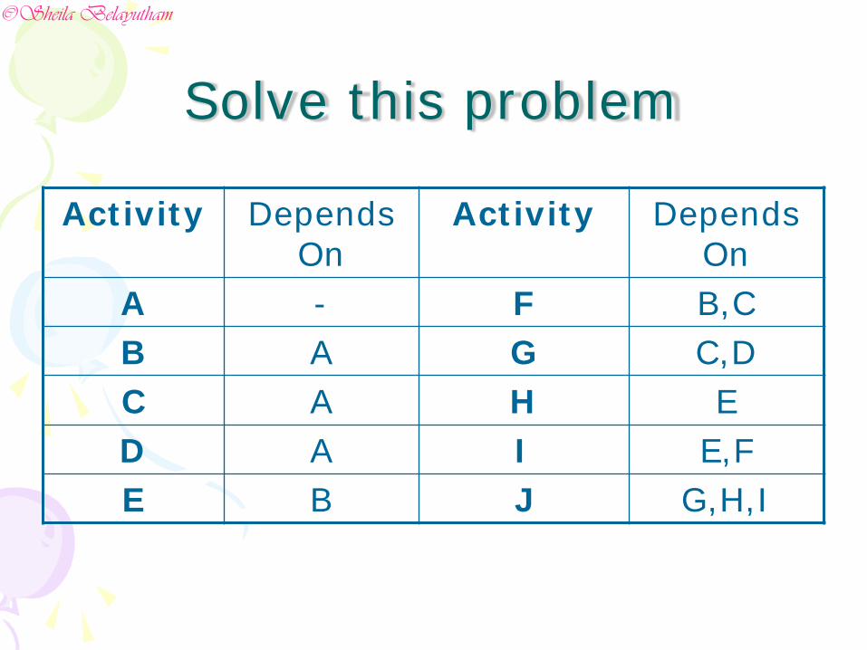
Activity Depends On
Activity Depends On
A - F B,CB A G C,DC A H ED A I E,FE B J G,H,I
Solve this problem
©Sheila Belayutham