Embed Size (px)
Citation preview
ProjectProject DeliverablesDeliverables
CIS 4328 – Senior Project 2And
CEN Engineering of Software 2
Second Semester Deliverables(anticipated)
Deliverable #6 – User Interface Design and Revisited Analysis Modeling
Deliverable #7 – Layered Architectural Design Deliverable #8 – Detailed Design - Iteration Planning
and Use Case Realizations – Context Diagrams only.
Deliverable #9 – Subsystem Design – InteractionDiagrams (both) and VOPC diagrams.
Deliverable #10 –Class Design and Implementation #1; First Functional Demonstration
Deliverable #11 – Final Deliverable: CompleteImplementation Model and Demonstration
including client testing.
Deliverable 6due: 1/23/2008 Start of class
Two Key Components 1. Revisiting Analysis Model
Use Case Specifications – Revisited Interaction Diagrams – Revisited
2. User Interface – Expanded and Revisited
General Details on Deliverable 6 (1 of 2)
Don’t forget hard copies of peer reviews to be brought to class. This is important. If you cannot be present on the date of the deliverable, give your review (in a sealed envelope) to a team member or physically drop it off in my office prior to class date/time. Remember: hardcopy – no email on this one.
When I bring up your CD, I should see one folder named Deliverable 6. As we add deliverables, the number of folders on your CD will increase and include a folder on Deliverable 7, etc. as we have done last semester.
Within this Deliverable folder (and others throughout the semester) I should see a Revisit Deliverable 5 folder (or other deliverable number as appropriate), a Management Folder, and an Artifacts Folder unless advised otherwise.
General Details on Deliverable 6 (2 of 2)
The Revisited Deliverable5 Folder is to contain the revisited Use-Case Specifications and the Revisited Interaction Diagrams (that is, Rose Model)
The Management Folder is to contain a files called TeamNumFile, Executive Summary, Statement of Work, Traceability Document, SQA Report, a folder containing Individual Schedules. Traceability Matrices are to be appended, prepended, or included in the Traceability Document.
The Artifacts Folder is to contain the User Interface Prototype (details ahead)
Organization. Organizing the deliverable (not the contents of each document) is the responsibility of the SQA role. The SQA’s grade will be slightly adjusted from the team grade relative to the organization of this deliverable.
Content. The team leader’s grade will be slightly adjusted from the team grade relative to the content of this deliverable.
1. Details on Revisiting Analysis Model (1 of 2)
Use case specifications are to have hyperlinks to the Domain Model or to the definitions sections in your Glossary. These links are to be relative and must be accessible on my computer.
Use case specifications are to provide a meaningful level of detail to support follow on design. If these specs are too high level and vague, they are unsatisfactory and will not support an effective design; too low level, and they constrain design. All Alternatives and Exceptions are to contain hot links as
appropriate, a concluding action (return to Step n or Use-case terminates here), and the complete set of behaviors.
There are to be no database references in your use-case specifications unless these refer to an external system.
1. Details on Revisiting Analysis Model (2 of 2)
Interaction Diagrams – Sequence. Ensure these are correct. Additional example(s) may be
found on my web page. (I have eliminated ambiguous examples and have inserted better examples) The use-case specification text should be inserted down the left margin of your sequence diagrams approximately in line with the objects that realize the behaviors to the right. This effort supports traceability.
Ensure control classes are indeed control (orchestrate) and entity classes provide core responsibilities and functionality. (Previous deliverables indicated that there was a real disconnect in understanding what these analysis class behaviors should be. In many cases, entity responsibilities were allocated to control classes.) Boundary classes are not to be expanded into ‘forms’ or ‘windows’ or anything resembling implementation. Remember, these will likely not morph into design classes.
These are to appear in your Rose Model as appropriate in the Logical View folder.
2. User Interface – Expanded and Revisited
I should be able to access (run through the templates) the UI within your deliverable submitted to me and execute it successfully. I should be able to navigate from screen to screen to pursue
some scenario from a use case. I should NOT have to hunt and peck and wonder…
Recognize that some (a few) of the windows / displays will be / may be hard coded and that demonstrated functionality may not be totally backed up with implemented code or efficient algorithms. But the implied functionality must be clear. This design should contain much more implied functionality than in Deliverable 3.
2. User Interface – (2 of 2)
This should be a significant refinement of your initial user interface prototype based on your increased knowledge and understanding of the requirements.
This user interface should demonstrate the vast majority of key items of functionality as found in the use cases.
In your classroom presentation, you are to demonstrate how your UI satisfies required functionality.
Utility and Usability Principles as cited in the lecture slides and your text will be emphasized in evaluation.
Verify your UI by running it against your use cases to ensure all functionality is captured.
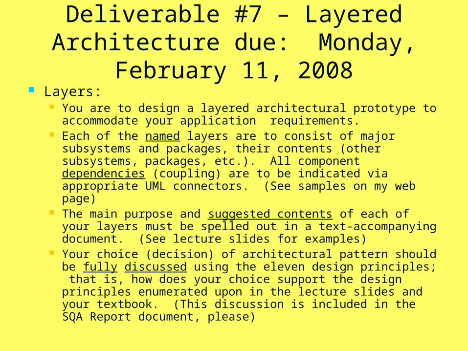
Deliverable #7 – Layered Architecture due: Monday, February
11, 2008 Layers:
You are to design a layered architectural prototype to accommodate your application requirements.
Each of the named layers are to consist of major subsystems and packages, their contents (other subsystems, packages, etc.). All component dependencies (coupling) are to be indicated via appropriate UML connectors. (See samples on my web page)
The main purpose and suggested contents of each of your layers must be spelled out in a text-accompanying document. (See lecture slides for examples)
Your choice (decision) of architectural pattern should be fully discussed using the eleven design principles; that is, how does your choice support the design principles enumerated upon in the lecture slides and your textbook. (This discussion is included in the SQA Report document, please)
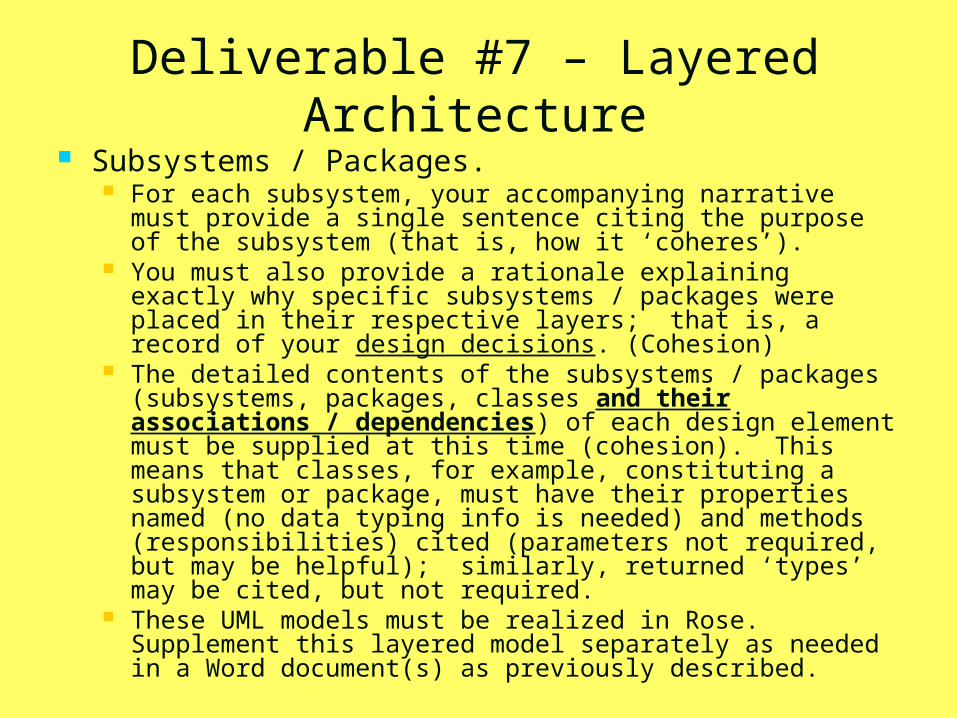
Deliverable #7 – Layered Architecture
Subsystems / Packages. For each subsystem, your accompanying narrative must
provide a single sentence citing the purpose of the subsystem (that is, how it ‘coheres’).
You must also provide a rationale explaining exactly why specific subsystems / packages were placed in their respective layers; that is, a record of your design decisions. (Cohesion)
The detailed contents of the subsystems / packages (subsystems, packages, classes and their associations / dependencies) of each design element must be supplied at this time (cohesion). This means that classes, for example, constituting a subsystem or package, must have their properties named (no data typing info is needed) and methods (responsibilities) cited (parameters not required, but may be helpful); similarly, returned ‘types’ may be cited, but not required.
These UML models must be realized in Rose. Supplement this layered model separately as needed in a Word document(s) as previously described.
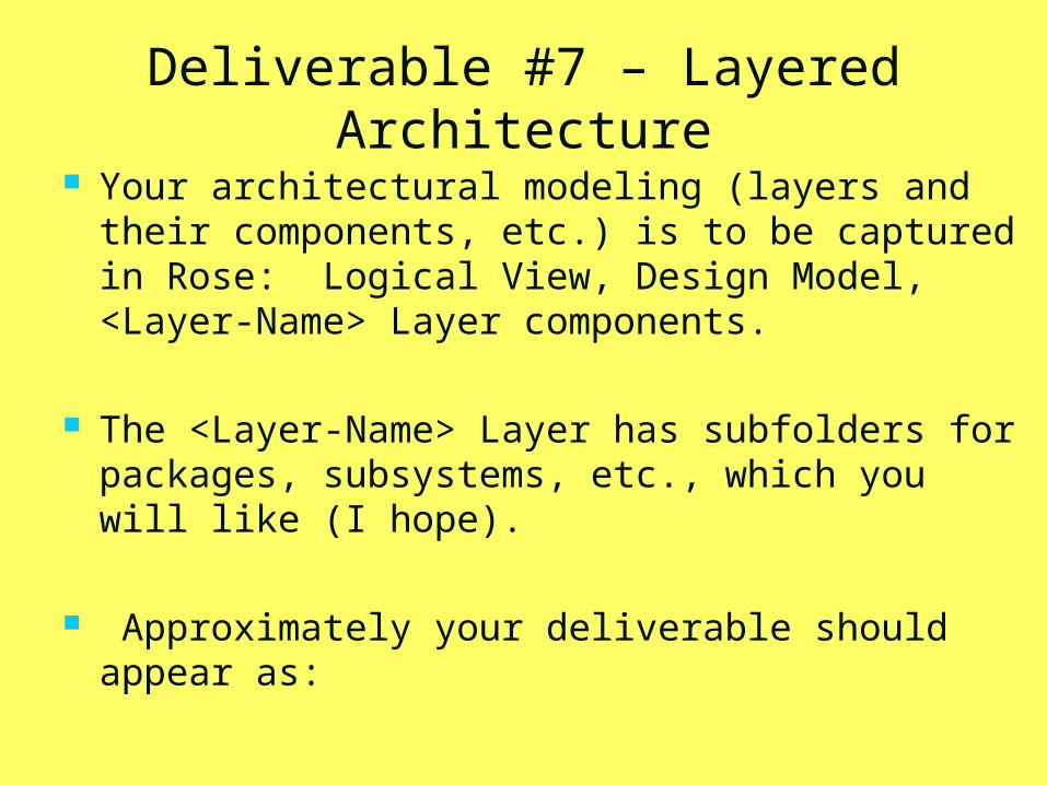
Deliverable #7 – Layered Architecture
Your architectural modeling (layers and their components, etc.) is to be captured in Rose: Logical View, Design Model, <Layer-Name> Layer components.
The <Layer-Name> Layer has subfolders for packages, subsystems, etc., which you will like (I hope).
Approximately your deliverable should appear as:
…
…
…
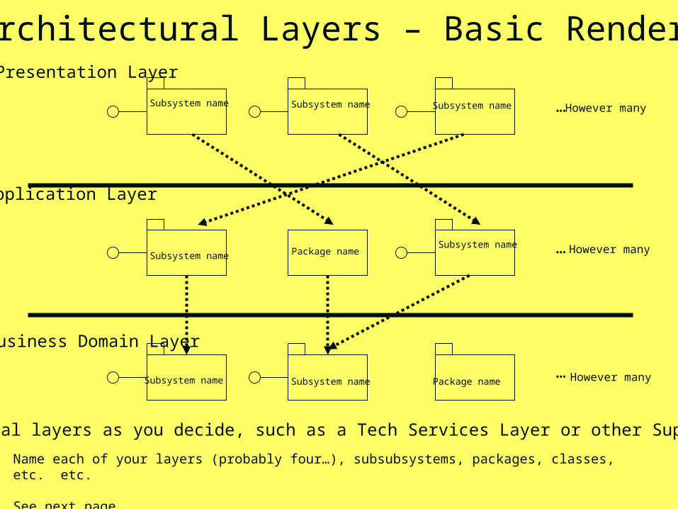
Presentation Layer
Application Layer
Business Domain Layer
Name each of your layers (probably four…), subsubsystems, packages, classes, etc. etc.
See next page.
Subsystem name Subsystem name Subsystem name
Subsystem name
Package name
Package nameSubsystem name
Subsystem name Subsystem name
However many
However many
However many
Architectural Layers – Basic Rendering
… additional layers as you decide, such as a Tech Services Layer or other Support Layer.
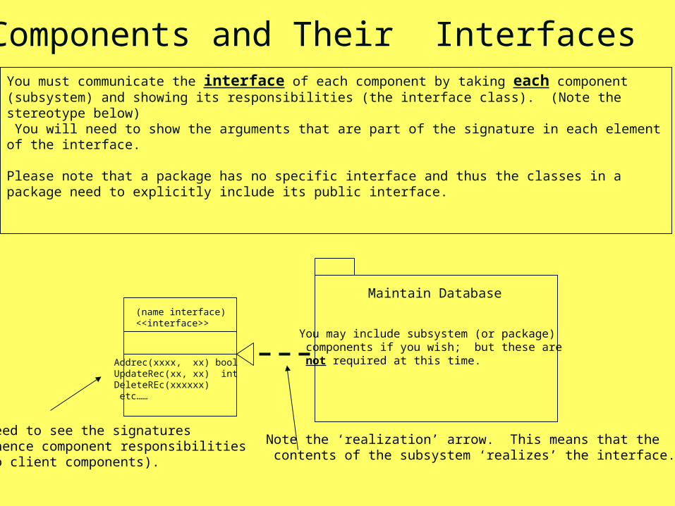
You must communicate the interface of each component by taking each component (subsystem) and showing its responsibilities (the interface class). (Note the stereotype below) You will need to show the arguments that are part of the signature in each element of the interface.
Please note that a package has no specific interface and thus the classes in a package need to explicitly include its public interface.
(name interface)<<interface>>
Maintain Database
Addrec(xxxx, xx) boolUpdateRec(xx, xx) intDeleteREc(xxxxxx) etc……
Components and Their Interfaces
Need to see the signatures(hence component responsibilitiesto client components).
Note the ‘realization’ arrow. This means that the contents of the subsystem ‘realizes’ the interface.
You may include subsystem (or package) components if you wish; but these are not required at this time.
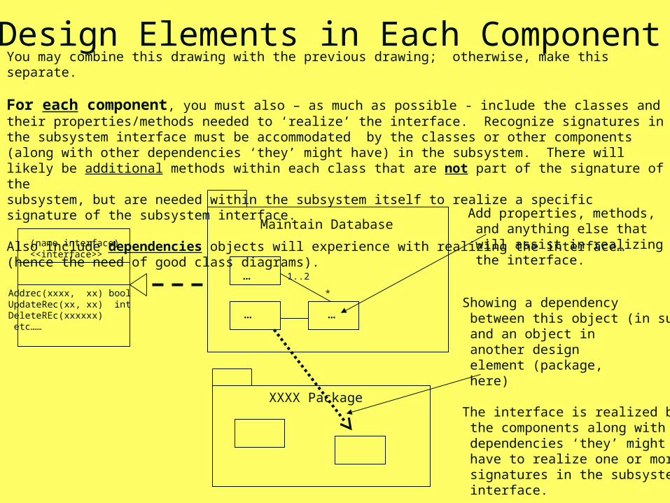
You may combine this drawing with the previous drawing; otherwise, make this separate.
For each component, you must also – as much as possible - include the classes and their properties/methods needed to ‘realize’ the interface. Recognize signatures in the subsystem interface must be accommodated by the classes or other components (along with other dependencies ‘they’ might have) in the subsystem. There will likely be additional methods within each class that are not part of the signature of thesubsystem, but are needed within the subsystem itself to realize a specific signature of the subsystem interface.
Also include dependencies objects will experience with realizing the interface…(hence the need of good class diagrams).
(name interface)<<interface>>
Maintain Database
Addrec(xxxx, xx) boolUpdateRec(xx, xx) intDeleteREc(xxxxxx) etc……
…
… …
Design Elements in Each Component
1..2
*
Add properties, methods, and anything else that will assist in realizing the interface.
Showing a dependency between this object (in sub) and an object in another design element (package, here)
The interface is realized by the components along with dependencies ‘they’ might have to realize one or more signatures in the subsystem interface.
XXXX Package
Deliverable #8: Detailed Design - Overview
due: Monday, 3 March 2008 0. Deliverable #8 Folder on CD. Include previous Spring folders also. 1. Management Reports:
Executive Summary, SOA, SOW, TeamNumFile, Individual Work Reports as usual. (Also don’t forget Peer Reviews)
SOA – is to include a brief discussion called a Technology Assessment. This is to include a preliminary assessment of the technologies your team plans to use, where (for what features) you plan to use them, sources of knowledge of these technologies and overall assessment of your team’s familiarities with these technologies. Include who knows what and the extent of that knowledge. Who will be the ‘primary’ and who will be the ‘secondary’ (or backup) on these technologies. This may be provided in matrix form. (done by SQA and team leader)
SOA – is to include a traceability update. This component of the deliverable is to include a map of use cases to design elements – namely subsystems, packages, or classes (within the layer where these items are found). This may be accommodated via traceability matrix having use-cases on one axis and design components on the other axis and an ‘x’ indicating the map where
SOW becomes more important as we launch into development. Projected times, accountability, and scheduling intermediary due dates is critical for the effective management of component development.
Deliverable #8: Detailed Design - Overview Use-Case Realizations due: Monday, 3 March 2006
2. Artifacts: Sequence Diagram and a Communications Diagram for use-case
scenarios to include the basic course of events and at least two other scenarios per use-case. So each use-case is to be have at least three of its scenarios mapped into at least sequence diagrams.
Do yourselves a favor. Don’t select the easiest alternative path. Also for alternative paths for CRUD considerations, these may not
need full expansion. Simple notes may be sufficient. Address those issues that require a good number of object collaborations so that you are certain responsibilities will be met.
Capture these models in Rose, Logical View, Design Package, Use Case Realizations Folder
More explanation follows in upcoming slides.
3. Deliverable 7 Revisitation. (Discussed ahead)
4. Prepare to Present – Class and especially sequence diagrams will be presented by some of the teams. All graduate teams will present, two or three undergraduate teams will present.
Date: to be decided, but likely March 8th.
More Discussion on Requirement 2: Use Case Realizations Static Component (Structural) Class
Diagrams
For each sequence diagram you develop, you are to produce in Rose the VOPC (View of Participating Classes) for that sequence diagram. These class diagrams may be grouped by use-case if you
wish (see two slides back) Be certain to include all the associations, dependencies,
multiplicities, aggregations, etc. All method names must be included. Include parameters
if they are known (and you may have a good guess for these…)
More Discussion on Requirement 2 – Use Case Realizations Dynamic Component (Behavioral)
Interaction Diagrams Sequence diagrams are to be fully annotated, as shown in lecture
slides. Include communications diagram too (use the F5 toggle) and include these in your Design Model in Rose.
This deliverable addresses design-level sequence diagrams, so entire flow with collaborating design elements (classes, subsystems, packages) must be captured . Where there is a reference to a subsystem, this component represented only by its interface is appropriate (lectures upcoming). For packages, however, since there is no specific interface, the public interfaces for each/any key classes participating in the sequence diagram scenario must be shown. (Parameters, again, need not be specified unless these are known. Clear responsibilities via method names and their objects is a must.)
Note subsystem interfaces do not require showing the ‘insides’ of the subsystem (subsystem realization). Detailed realizations of these interfaces is the primary focus of Deliverable #9. But the responsibilities of the subsystems and classes within packages (via their individual interfaces) must be shown.
More Discussion on Requirement 3: Re-Visitation of Deliverable 7
Revisit your architectural design layers and design elements within these layers.
Look in particular at the design components. Add any classes to included subsystems or subsystems
to any layers, or move subsystems around, or move packages, classes around, etc. as you feel appropriate.
Please note that these layers should not all consist of subsystems. This would be obscuring considerable design detail. A good layered architecture should include subsystems for sure. But individual packages of related capabilities is an expectation too.
I look forward to seeing your revisions to Deliverable 7 model. Text descriptions of any model changes should be found in the Executive Summary.
Deliverable #9 – Detail Design Subsystem Design and Realization – due:
3/24/2008 Include ONLY Deliverable 6 through 9 folders on the CD, please. Include the following items only:
Management Folder: Executive Summary SOW Technology Assessment (see ahead) Questions / Answers at end of Deliverable 9 Guidance slides.
Artifacts Folder Rose Model to include Subsystem design
Revised Deliverable 8
Management Folder Exec Summary as usual SOW as usual Technology Assessment-
Tell me what technologies you are using (again) and Map out your programming development strategy (who is doing what using
specific technologies / platforms, etc. You should have a primary and alternate (at least) for each major task.
Map out your application programming and map this discussion back to your design.
You may use any format you wish including a table, an excel spreadsheet or plain text.
Questions / Answer slides
Artifacts FolderFor each subsystem, you are to provide an interaction diagrams for each use-case’s basic
course of events and at least two alternative and at least two exceptional scenarios. (See lecture
32) Please note that these interaction diagrams are to
be racheted down to the class level. For those use-cases that have interfaces for subsystems
(deliverable 8), you must include these diagrams but then you must also expand (realize) in supplementary sequence diagram the subsystem classes that realize the interface you designed in deliverable 8.
This is the primary emphasis in Deliverable 9. You are also to provide the internal structure of
your subsystems, like slides 4 and 6 in lecture 33. This is your VOPC. These are to be fully annotated (dependencies, communications, multiplicities, etc.)
Do not worry about parameters, etc. within classes, as this is Deliverable 10.
Artifacts Folder (continued) Do include the use-case text down the left
margins as done in Deliverables 7 and 8 Your objects in your VOPC (as well as
sequence diagrams) are to include tags. Examples include: tags such as where a class
resides (package, etc.) – recall the following tags from class lecture slides and discussions:
University Artifacts java.sql External Interface Persistent tags where appropriate too
Deliverable #9 - Questions What is a proxy class and what is its purpose? What do we mean by a dependency?
What are the pros and cons of dependencies? Under what kind of situation is a subsystem
interface sufficient in a sequence diagram? In behavioral modeling, when must the interface be
realized? How is it done? What kind of model(s) is/are used to capture the details of the inner workings of a subsystem?
Why should dependencies on a subsystem be on the subsystem interface?
Turn these in via a separate Word document within the Management Folder. Be certain you put some time on these, as you may well see these again.
Deliverable 9 – Last Thoughts
You have plenty of time for this one, but it is a very important one and should involve all team members in the modeling exercises.
Last time this assignment was given (this one is modified quite a bit though…) it was due March 16th.
Note there are two additional deliverables coming: one dealing with class design and the ‘wrap up’ (demo) one.
You will have time and some class days to work on these too. Deliverable 9, in my judgment, the last big one.
Of course we have Spring Break from March 17-21st and I will be gone the week of April 8th. Probably Deliverable 10 will be due April 15th perhaps before. Deliverable 11 will closely follow in the last week of classes.
You all have done well. Keep up the good, steady work!
Deliverable #10Class Design and Implementation #1 due Friday,
11 April. Zip Deliverable and Email and use Digital Dropbox
In addition to Executive Summary, SOW, and SQA: Class Design: Ensure all methods in your Use Case
Realizations have full signatures (this means include parameters) in their calling sequences.
Test Development Part 1: Create and document test suites: Certainly use your use cases, catalog these via number, purpose, scope, results, and assessment of each test. You need not run these tests in this deliverable, but your test suites, test design, objectives, validation plan, etc. must be developed and document.
Revise VOPCs: Using Rose, ensure your classes and attributes are all correct by revising your VOPCs ensuring that all connections are either associations or dependencies. Ensure signatures (with parameters) are shown.This can be shown by clicking on objects across the top of sequence diagrams and filling in the window specifications.
Deliverable #10Class Design and Implementation #1
Plan on demonstrating your deliverable, that is be able to defend your test plan.
At least two grad teams will present; at least three undergraduate teams will present.
More later on the details on this presentation. Of course, there is to be a Management Folder,
Artifacts folder and Revisited Deliverable 9 folder.
Include all Spring Deliverable Folders ONLY. (So your CD should have five folders labeled Deliverable 6 …. Deliverable 10)
Team leader responsibility.
Deliverable #11Final Implementation and Demonstration. Due:
4/21/08 Continuation / extension of Deliverable #10: Management Folder:
Include Executive Summary, SOW, and SQA documents (no individual logs required). Also include a retrospect on your Technology Assessment. How did it work (degree of success)? Revisions?
Artifacts Folder: Test Plan and Implementation – Word document is
sufficient. This should be a significant document! All previous Rose Models should be available
Source Code delivery by design unit (see ahead)
Demonstration
Deliverable 11 - Test Plan / Implementation
Test Implementation: Run each test in accordance with the detailed test plan developed in deliverable 10. Document test results. Again, categorize the tests by use-cases,
number the tests, cite objectives of each test, required data, and results of running each test.
There should be a large number of tests you undertake. Documenting a number of these should not be difficult, but it will take time!!
You will be required to demo these in class and defend them.
Deliverable #11 - Source Code Delivery
Source Code: Your deliverable is to include your source-level components. organized ‘by design unit’ (that is, package,
subsystem), ‘by component’ (within these higher level components).
Please note: Your source code absolutely must be internally documented with meaningful, guiding comments. These will be reviewed very carefully!!!
Deliverable 11 - Demonstration On the day you are demonstrating your projects (staring
April 21st – at least this is the plan at the time of this writing…), you are to provide to me a hardcopy of your use cases. You are to provide me with hardcopies one full class prior to the demonstration. I will arbitrarily select one or two of these for you to demonstrate during class. My plan is to use an overhead and project the use case (or two) onto a side board so the class can see the use-case while you demonstrate the functionality via your test scenarios.
You will be required to demonstrate the functionality of your working application by validating the use-case.
You may also be asked some general questions.
It is anticipated that your demonstration with questions, etc. should not last beyond thirty minutes.
If you need separate computer support, you should plan to go to class early to set up / connect to whatever you need.
Good luck and have fun!