Embed Size (px)
Citation preview

1
Project Description: Tri-Valley 2002 Capacity Increase Project
[This description is taken from PG&E’s Proponent’s Environmental Assessment (November 1999). Note that the Home Page for this website includes a link to a Project Area Map.]
1. PROJECT OVERVIEW
PG&E states that the Tri-Valley 2002 Capacity Increase Project is needed to meet the projected electric demand in the Cities of Dublin, Livermore, Pleasanton, and San Ramon, and in portions of unincorporated Alameda and Contra Costa Counties adjacent to these cities. New transmission and distribution facilities are needed to serve existing and approved development in the Tri-Valley area. This section provides a complete description of the project and all temporary and permanent facilities that will be constructed. The major elements of the project are shown in the map on this website and include:
Phase 1 (North and South Areas):
• Constructing two new distribution substations. The proposed Dublin Substation would be located 3 miles north of Interstate 580 and 1 mile east of Tassajara Road in Contra Costa County. The proposed North Livermore Substation would be located 3 miles north of Interstate 580 at the intersection of May School Road and North Livermore Avenue.
• Modifying the existing Vineyard Substation to include a 230 kV transmission interconnection.
• Installing 7.9 miles of new 230 kV overhead double-circuit transmission line in PG&E’s existing vacant easement to serve the Dublin and North Livermore substations.
• Installing 2.8 miles of new 230 kV overhead double-circuit transmission line and 2.7 miles of 230 kV underground double-circuit transmission line to serve the Vineyard Substation.
• Installing a transition structure to convert the 230 kV overhead transmission line to a 230 kV underground cable system to serve the Vineyard Substation.
Phase 2 (North Area):
• Constructing approximately 10 miles of new 230 kV double-circuit transmission line in PG&E’s existing vacant easement from the Contra Costa-Newark 230 kV line southeast to the Tesla Substation. This will connect the Dublin and North Livermore Substations directly to the Tesla Substation.
2. EXISTING REGIONAL ELECTRIC SYSTEM IN THE TRI-VALLEY AREA
An electric power system consists of power plants, transmission substations, distribution substations, and overhead or underground electric lines. Power is delivered from the generating plants to customers through wires and cables, but the power is converted to higher and lower voltages several times for different purposes. At the generating plants, the electric power is “stepped up” to a higher voltage, known as the transmission voltage.
PROJECT DESCRIPTION
2
Stepping up to a higher voltage reduces the amount of current that flows through the wires, and therefore allows the power to be delivered from the generating plants to the major load centers with fewer wires. Once the power has been delivered to the major load centers, it is “stepped down” to a lower voltage for delivery to individual customers. Transmission and distribution substations are used to “step up” or “step down” the voltage and to route the power over the transmission and distribution lines. In the PG&E transmission system, power is transmitted at 500, 230, 115, 70, and 60 kV.
In the Tri-Valley area, the electric power is transmitted to the regional substations at voltages of 230 kV and 60 kV. The power is then distributed to customers using overhead or underground distribution lines at voltages of 12 kV or 21 kV. The local delivery system, usually at 12 or 21 kV, is further stepped down for individual customer use.
2.1 Transmission System Eight 230 kV transmission circuits run along the perimeter of the Tri-Valley area. Four of these 230 kV circuits run just northwest of the Tri-Valley area. These are the Pittsburg-Moraga #3 circuit, the Pittsburg-Newark circuit, and the Contra Costa-San Mateo #1 and #2 circuits. Two 230 kV circuits run along the eastern and southern edges of the Tri-Valley area. These are the Contra Costa-Newark #1 and #2 circuits. These six 230 kV circuits deliver power from the Pittsburg and Contra Costa power plants to Bay Area load centers. Two of the circuits (Pittsburg-Moraga #3 and Contra Costa-Newark #1) deliver power to the Tri-Valley area. In addition to these six 230 kV circuits, two circuits skirt the southern edge of the Tri-Valley area. These are the Tesla-Newark and the Tesla-Ravenswood 230 kV circuits. These circuits deliver power from the 500 kV Tesla Substation to Bay Area load centers. The PG&E 500 kV system is part of the Western States power grid, which interconnects inter- and intra-state power plants.
There are three sources of power into the Tri-Valley 60 kV system. Two of these sources are served from the 230 kV lines described above. They are the 230/60 kV, 88 megavolt amperes (MVA) transformer at the San Ramon Substation (which is served from the Pittsburg-Moraga #3 line) and the 230/60 kV, 90 MVA transformer at the Las Positas Substation (which is served from the Contra Costa-Newark #1 line). The third source into the Tri-Valley 60 kV system is the 115/60 kV, 75 MVA transformer at the Newark Substation.
2.2 Distribution System The electric distribution system in the Tri-Valley area is comprised of both 21 kV and 12 kV distribution lines. All substations except Sunol have experienced peak loading beyond their capacity.
21 kV System The existing 21 kV distribution system is supplied by three major substations: San Ramon, Vineyard, and Las Positas.
San Ramon Substation. The San Ramon Substation is located in southern San Ramon and serves customers in San Ramon, Dublin, and portions of Pleasanton, as well as unincorporated areas of Alameda and Contra Costa Counties that surround these cities. The substation consists of four 230/21 kV, 75 MVA power transformers. The San Ramon
PROJECT DESCRIPTION
3
Substation is supplied by the 230 kV Pittsburg-Moraga #3 line. The station experienced a demand of 281 MW during the 1998 summer peak load period.1
Vineyard Substation. The Vineyard Substation is located in central Pleasanton and serves customers in the City of Pleasanton and in unincorporated areas of Alameda County. The Vineyard Substation is served by the Las Positas-Livermore-Vineyard and San Ramon-Radum-Vineyard 60 kV lines. The substation currently consists of one 230/60/21 kV, 75 MVA power transformer and one 60/21 kV, 75 MVA power transformer. However, the distribution capacity is limited by the 60 kV transmission system. Based on the 1999 projected area load, the transmission constrained capacity limit of the Vineyard Substation is 55 MVA when the 60 kV transmission system is operated in its normal looped configuration.2 When the 60 kV system is operated in a temporary radial configuration, the transmission constrained capacity limit of the Vineyard Substation increases to 79.9 MW. This station experienced a demand of 60.7 MW during the 1998 summer peak load period.
Las Positas Substation. The Las Positas Substation, located in the eastern part of Livermore, serves customers in the City of Livermore and surrounding unincorporated areas of Alameda County. It is supplied by the 230 kV Contra Costa-Newark #1 line. The substation currently consists of two 230/21 kV, 45 MVA power transformers and one 230/21 kV, 75 MVA power transformer. The Las Positas Substation experienced a demand of 90.1 MW during the 1998 summer peak load period.
12 kV System The existing 12 kV distribution system is supplied by five substations: Livermore, Vasco, Sunol, Radum, and Parks. All of these substations receive power from the existing 60 kV transmission system. A description of the substations follows:
Livermore Substation. The Livermore Substation is located in Livermore and supplies customers in the Central Livermore area. The station currently consists of two 60/12 kV, 12.6 MVA power transformer banks. This station experienced a demand of 27.7 MW during the 1998 summer peak load period.
Vasco Substation. The Vasco Substation is located on the eastern boundary of Livermore and services customers in the area east of Vasco Road. The station currently consists of one 60/12 kV, 8.7 MVA power transformer bank and one 60/12 kV, 9.3 MVA power transformer bank. The substation experienced a demand of 24.4 MW during the 1998 summer peak load period.
Sunol Substation. The Sunol Substation is located east of Sunol and services customers in the Sunol area. During the 1998 summer peak period, the station consisted of one 60/12 kV, 4.5 MVA power transformer bank. The 1998 summer peak load on Sunol Substation was
1 Of this amount, 14.9 MW was fed from San Ramon Substation to an adjacent distribution planning area. “Peak load period”
is the amount of energy carried by a utility system during a specific time period (typically 15 minutes). Peak load determines the required system capacity and can be determined at a regional or system-wide level.
2 A radial configuration for a substation means that only one transmission line supplies a substation. An outage of the transmission line would also cause an outage to the substation it supplies. In a looped configuration, two or more lines are connected to the substation and at least one line can supply the substation if the other lines incur an outage. A looped configuration provides more reliability.
PROJECT DESCRIPTION
4
5.5 MW. In 1999, the transformer bank at Sunol Substation was replaced with a 60/12 kV, 12.5 MVA transformer.
Radum Substation. The Radum Substation is located just north of the Vineyard Substation and services customers in the City of Pleasanton, portions of west Livermore, and unincorporated areas of Alameda County. The station currently consists of two 60/12 kV, 12.6 MVA transformers. The station experienced a demand of 30.8 MW during the 1998 summer peak load period.
Parks Substation. The Parks Substation, located in Camp Parks, serves customers in portions of Dublin and Pleasanton. The station currently consists of one 60/12 kV, 4.5 MVA power transformer bank. The station experienced a demand of 5.1 MW during the 1998 summer peak load period.
Single-Customer Substations. In addition to the substations described above, there are also three single-customer substations and one customer-owned substation. These single-customer substations are Bay Area Rapid Transit (BART), Kaiser, and Iuka. The BART Substation is located in Dublin and supplies electric power to the BART system. The Kaiser Substation provides electric service to the Kaiser facility at 3000 Busch Road in Pleasanton. The Iuka Substation provides electric service to the Lone Star Cement Plant east of Stanley Boulevard in Pleasanton. The customer-owned Cal Mat Substation supplies electric service to the Cal Mat facility on Stanley Boulevard in Pleasanton.
3. Description of the Project
3.1 North Area—Phase 1 Two new 230 kV substations will be dedicated to serving the load growth north of Interstate 580, and a new 230 kV transmission line in PG&E’s existing vacant right-of-way will provide power to the substations. Each substation will have an associated distribution system to provide power to customers. Detailed information on all project components and construction methods is provided below.
North Livermore and Dublin Substations The North Livermore and Dublin Substations will be un-manned, fenced and walled, remote-controlled facilities on 5-acre parcels. They will require weekly inspections of equipment for normal maintenance. During emergency operations, there may be numerous visits by up to 10 persons for switching and repair work. The North Livermore Substation will be constructed inside an earthen landscaped berm, with a precast concrete wall structure and vegetation appropriate for the setting. The substation will be set back approximately 60 feet from North Livermore Avenue to allow for any future widening of the roadway. The setback will also accommodate the length of driveway required to handle a mobile tractor trailer in the event of a transformer exchange. This will allow the normal traffic flow on North Livermore Avenue to be uninterrupted.
The Dublin Substation will be located just north of PG&E’s existing right-of-way, approximately 1 mile east of the proposed extension of Tassajara Road in Contra Costa County. The proposed substation site is located in rolling rangeland used for cattle grazing.

PROJECT DESCRIPTION
5
PG&E proposes to construct the Dublin Substation without landscape screening during its initial years of operation. The ranch parcel is remote and lies north of an approved development within Alameda County, and south and east of approved development in Contra Costa County. PG&E estimates that it may be 10 to 15 years before the Dublin Substation site becomes surrounded by residential development. Once development agreements have been finalized, PG&E will install landscape measures appropriate to the surrounding setting and uses. The original purchase of 5 acres will allow for the additional placement of appropriate screening around the working substation without service interruptions. Approximately 0.4 miles of existing rocked farm road will be improved to allow for two-way construction traffic. An additional 0.5 miles of new all-weather access road will need to be built to the substation.
The interior of both the North Livermore and Dublin Substations will be paved with a 20-foot wide ring road to allow for maintenance and access to all large equipment within the substation. The remainder of the substation surface will be compacted and rocked with gravel to provide an all-weather surface. Four 21-foot by 36-foot metal-clad switchgear buildings will also be included. The spill prevention, control, and countermeasure (SPCC) ponds will be consistent with Title 40 of the Code of Federal Regulations. Oil containment facilities will be sized to contain 110% of the oil volume of the largest oil filled equipment (45 MVA transformers).
Each substation will ultimately consist of four 230/21 kV, 45 MVA transformers with a total capacity of approximately 180 MW. As described previously, these substations will serve the existing and planned developments located north of Interstate 580.
Substation Equipment Major equipment at both the North Livermore and Dublin Substations will include the following:
• 230 kV bus structures including 230 kV bus sectionalizing switches (for transmitting 230 kV power)
• Two 230 kV circuit breakers (for switching and protecting 230 kV transmission lines from the Newark Substation and Contra Costa Power Plant)
• Four 230/21 kV power circuit breakers (for switching and protecting four 230/21 kV power transformers)
• Four 230 kV distribution power transformers
• Four 21 kV metal-clad switchgears
• Capacitor banks
In addition to the above, PG&E will install related electrical equipment at the North Livermore and Dublin Substations, such as 230 kV disconnecting switches, reactors, instrument transformers, metal-clad switchgear, protective relaying, metering and control equipment, supervisory control and data acquisition equipment, telemetering equipment, auxiliary alternating current (ac) and direct current (dc) power system, electrical grounding system, and underground conduits or trench systems.

PROJECT DESCRIPTION
6
230 kV Transmission Line The proposed 230 kV transmission line route is shown on the map included on this website. It will connect to PG&E’s existing Contra Costa-Newark transmission line and will terminate in the west at the proposed Dublin Substation. The maximum right-of-way needed is 60 feet on each side of the centerline (or 120 feet total). The route crosses primarily grassland and is within an existing PG&E vacant right-of-way that is approximately 75 feet wide. Approximately 45 additional feet of right-of-way would need to be acquired (or about 22 feet on each side of the existing easement).
From the Contra Costa-Newark Line, the route heads west for 6.9 miles and crosses the Contra Costa-Alameda County line. The first 4 miles traverse due west. At the 4-mile mark, the route turns 20 degrees in the southwest direction. It continues 0.7 miles and then makes a 12 degree turn towards the north and continues for 1.3 miles. The route makes a final 8 degree turn north, heading almost due west, and traverses 0.9 miles before terminating at the Dublin Substation site. The total distance for the route is 6.9 miles.
A new 230 kV transmission line along North Livermore Road is also necessary to connect the North Livermore Substation to the new transmission line described above. The connecting line will travel south along the west side of North Livermore Road from the existing corridor to the new substation. The total distance for the route is approximately 1 mile.
The proposed 230 kV transmission line connecting the North Livermore and Dublin Substations to the Contra Costa-Newark line will support two circuits of conductor known as 1,113,000 circular mils of all-aluminum conductor (1113 kcmil AAC). This conductor is 1.22 inches in diameter. Each circuit will consist of three phases (three wires) and one shield wire at the top of the tower to protect the system from lightning strikes.3 A new 80- to 150-foot lattice-type steel tower structure compatible with the existing Contra Costa-Newark 230 kV double-circuit transmission line will be used to intercept circuit #2 of the Contra Costa-Newark 230 kV transmission line. A new 60- to 80-foot single-circuit lattice tower will be installed on each side of the new double-circuit structure to allow each of the two circuits of the new line to pass under circuit #1 of the Contra Costa-Newark line. This configuration of three lattice-type steel structures will facilitate the transition to lattice towers or tubular steel pole structures (ranging in height from 80 to 150 feet), which will be used from the intersection point to the new Dublin and North Livermore Substations.
Distribution Lines Ultimate distribution circuit construction from the North Livermore and Dublin Substations would involve the installation of twelve 21 kV distribution circuits from each substation, with some potentially located in PG&E easements. The 21 kV distribution circuits will be a combination of overhead conductors on poles and underground cable in conduit.
3.2 North Area—Phase 2 When the transformer loading at the North Livermore and Dublin Substations approaches the current carrying limit of the Contra Costa-Newark 230 kV circuit, it will be necessary to
3 The shield wire could include a fiber-optic cable system.
PROJECT DESCRIPTION
7
construct approximately 10 miles of double-circuit, looped-configuration transmission line to the Tesla Substation . This line would be constructed from the present loop location on the Contra Costa-Newark line using PG&E’s vacant easement position through the Altamont Pass to a breaker position at Tesla Substation.
PG&E owns a 75-foot-wide transmission easement acquired in the 1960s that extends from Tesla Substation on Patterson Pass Road in eastern Alameda County to the San Ramon Substation in the City of San Ramon on Alcosta Boulevard. The proposed Phase 2 plan uses this easement from its intersection with the Contra Costa-Newark 230 kV transmission line near Vasco Road to its origin at Tesla Substation. This easement traverses gently to moderately sloped grazing land, mostly encumbered with windfarms through the Altamont Hills. Some relocations of this easement may be necessary at the Browning Ferris Industries (BFI) Landfill at Vasco Road and within some of the windfarm development where there are encroachments on PG&E’s easement.
3.3 South Area The Tri-Valley Project includes system reinforcement in the South Livermore area. The project components are shown on the map in this website are listed below. The project includes:
• Construction of a 2.8-mile-long overhead and 2.7-mile underground 230 kV double-circuit transmission line loop from PG&E’s existing Contra Costa-Newark transmission line corridor to the Vineyard Substation.
• Modification of the Vineyard Substation to accommodate the new 230 kV transmission circuits.
• Installation of additional 21 kV distribution circuits from Vineyard Substation.
Vineyard Substation Modification One existing 60/21 kV transformer bank would be replaced with a 230/21 transformer bank. Accordingly, the existing 230/60/21 kV transformer bank would be changed from 60 kV to 230 kV. The existing 60 kV circuit switches would be changed to 230 kV switches. Three existing 60 kV overhead line terminations would be removed and two new 230 kV underground cable termination stations would be installed. One 230 kV power circuit breaker would be installed for 230 kV underground cable line. Two 21 kV outlet circuits would be built. The area that would be occupied by the new equipment is within the existing footprint of the substation.
230 kV Transmission Line
Overhead Segment
The proposed overhead 230 kV transmission line route would originate approximately 1.0 mile east of the entrance to the Vallecitos Nuclear Center along Route 84. The line would originate in PG&E‘s existing Tesla-Newark transmission line corridor, which is occupied by four rows of standard lattice steel towers. It would connect with the existing Contra Costa–Newark transmission line and travel north for approximately 2.8 miles through moderately steep sloped rangeland toward the City of Pleasanton from the south. The route would
PROJECT DESCRIPTION
8
transition to underground approximately halfway to the Vineyard Substation. The facilities and equipment would be the same as described for the North Area overhead transmission line except that only lattice steel towers will be used.
To connect the new Vineyard 230 kV transmission line to the Contra Costa-Newark 230 kV line, a new single-circuit lattice tower and two short dead-end towers would be installed in a parallel position just south of, and adjacent to, the Contra Costa-Newark line. Each dead-end tower would carry two circuits northward under the existing transmission line to a new tower located between the Contra Costa-Newark line and the Stanislaus-Newark line. From this tower, the double-circuit lines would pass over the lines in the corridor and northward to the Vineyard Substation.
Transition Structure The transition structure will be constructed below the natural ridgeline where, in part due to landscape screening, it will not be visible from the City of Pleasanton. The transition structure will consist of two dead-end structures for terminating both 230 kV overhead circuits, two low-profile support structures for cable terminations and lightning arresters, and two splice vaults for splicing cables and facilitating access for future repairs to the cables or cable terminations. Other equipment located at the site will include cable sheath arresters, conductor jumpers, grounding conductors, fiber-optic facilities, fencing, and outdoor lighting. The layout will require an area of approximately 0.2 to 0.5 acres, including vehicle access, and will be graded flat or in a terraced layout. An access road to the transition structure will be built from the City of Pleasanton Kottinger Ranch water storage tank site. Underground Segment The underground segment begins at Milepost M2.8 and traverses the ridge to the existing Kottinger Ranch water tank in south Pleasanton. To obtain overhead transmission line easements north of the access road to the city’s water tank, residents would have to be displaced from their homes. PG&E therefore determined that an underground transmission line was the most feasible option.
After passing the water tank, the route continues down an existing paved road and into city streets. The city streets include Benedict, Smallwood, and Bernal. The underground segment would continue down Bernal until reaching the existing Vineyard Substation. The underground easement will be 30 feet wide in open country with an additional 30-foot-wide temporary construction easement. Within the City of Pleasanton, the underground transmission line would be placed within city streets. One trench approximately 3 to 5 feet wide by 6 to 8 feet deep would be required.4 The 230 kV underground transmission line would consist of six cross-linked, polyethylene-insulated, solid dielectric cables (two circuits) in a double-circuit duct bank. The duct bank would consist of nine 6-inch polyvinyl chloride (PVC) ducts, encased in concrete in a trench between the transition structure at Milepost M2.8 and the Vineyard Substation at Stanley Boulevard and Bernal Avenue.
Transmission Line Right-of-Way 4 Although the 230 kV underground transmission line will only require a 3-foot-wide trench, the portion of the route that is
between Hearst Drive and Arroyo Valle may require a wider trench to accommodate future distribution circuits. The 230 kV circuit will need to be offset from the anticipated 21 kV distribution circuit due to access and heat rejection requirements. Therefore, the trench in this portion of the route will be constructed to a 5-foot width. By constructing a combined trench, PG&E will minimize construction impacts in the City of Pleasanton.
PROJECT DESCRIPTION
9
The proposed Vineyard 230 kV extension from the Tesla-Newark corridor will require the modification of an existing tower and two short dead-end tap towers within PG&E’s existing corridor south of Route 84. Once the proposed line travels north and clears the existing PG&E easements, a new 120-foot easement will be required. This easement will place basic restrictions on development within its boundaries. The present and foreseeable land use for the proposed alignment is cattle grazing with a County General Plan minimum development requirement of 200 acres per dwelling unit. The majority of the alignment traverses fairly rugged terrain with side slopes exceeding 35 percent. Once the alignment crosses over the ranch property, it approaches a ridgeline that approximates the southern boundary of the City of Pleasanton. The proposed overhead alignment south of this point back to Route 84 is not visible from within the city.
At the approximate city limit line, PG&E will transition the overhead electrical circuits to a solid dielectric underground cable system. There are two typical kinds of high-voltage underground transmission systems. The first, a “pipe-type” system, is a low-pressure, oil-filled, encased system used to control the heat generated in the cables. The second, a solid dielectric system, includes cable of a sufficient size in a PVC duct and is easier to install and repair. The solid dielectric system therefore avoids the complexity of oil-filled piping and oil pumping stations that are needed approximately every 3,000 feet. PG&E is working with representatives of the transition structure property to construct the underground alignment with consideration for future access plans. PG&E would construct an all-weather road over the top of the cable system for access and protection. Once the cable system traverses the undeveloped property, it will enter city streets and be designed and constructed to comply with City of Pleasanton franchise requirements.
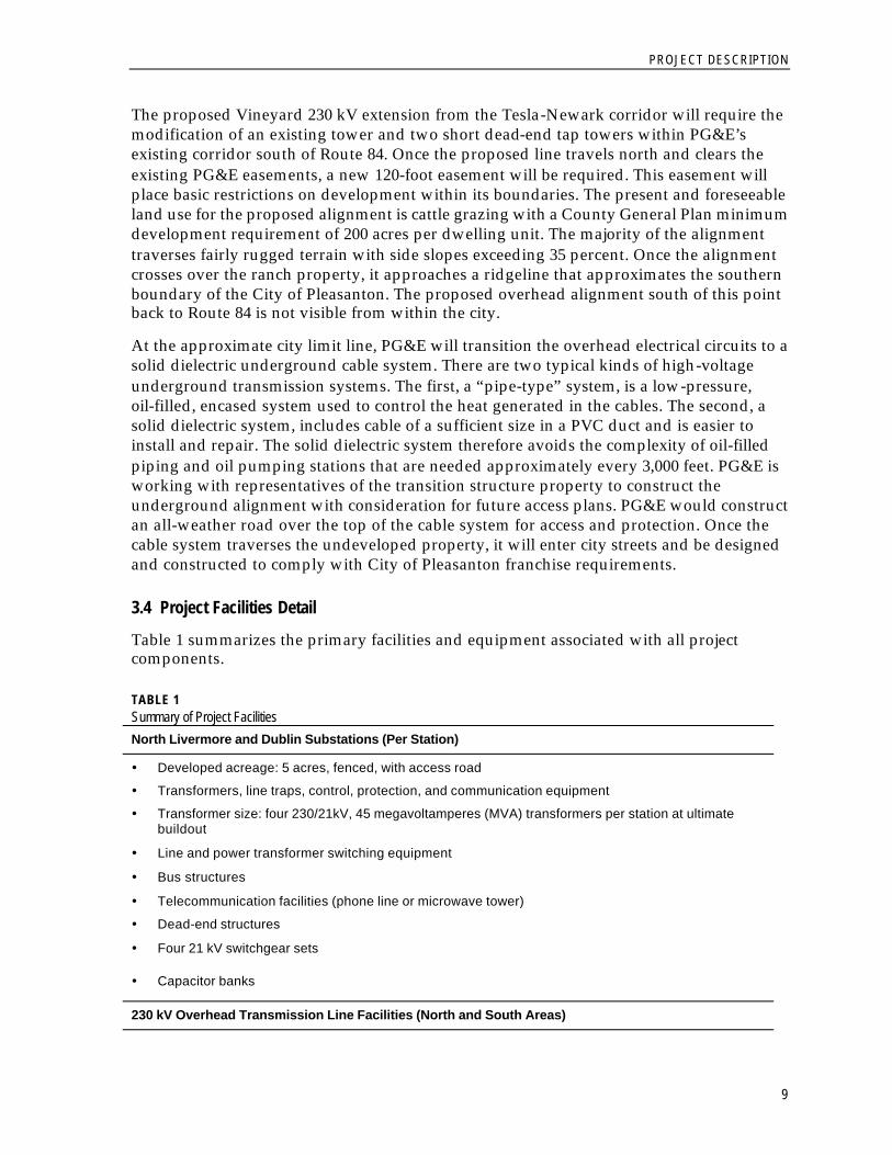
3.4 Project Facilities Detail
Table 1 summarizes the primary facilities and equipment associated with all project components.
TABLE 1 Summary of Project Facilities North Livermore and Dublin Substations (Per Station)
� Developed acreage: 5 acres, fenced, with access road
� Transformers, line traps, control, protection, and communication equipment
� Transformer size: four 230/21kV, 45 megavoltamperes (MVA) transformers per station at ultimate buildout
� Line and power transformer switching equipment
� Bus structures
� Telecommunication facilities (phone line or microwave tower)
� Dead-end structures
� Four 21 kV switchgear sets
� Capacitor banks
230 kV Overhead Transmission Line Facilities (North and South Areas)
PROJECT DESCRIPTION
10
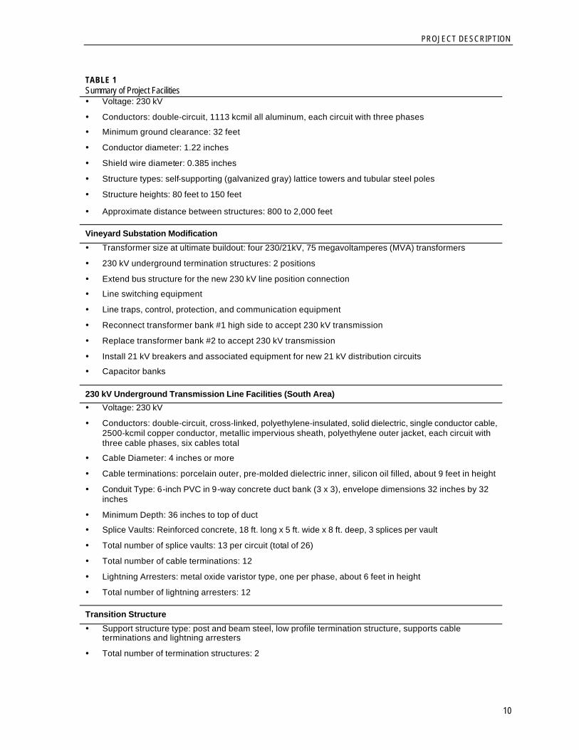
TABLE 1 Summary of Project Facilities � Voltage: 230 kV
� Conductors: double-circuit, 1113 kcmil all aluminum, each circuit with three phases
� Minimum ground clearance: 32 feet
� Conductor diameter: 1.22 inches
� Shield wire diameter: 0.385 inches
� Structure types: self-supporting (galvanized gray) lattice towers and tubular steel poles
� Structure heights: 80 feet to 150 feet
� Approximate distance between structures: 800 to 2,000 feet
Vineyard Substation Modification
� Transformer size at ultimate buildout: four 230/21kV, 75 megavoltamperes (MVA) transformers
� 230 kV underground termination structures: 2 positions
� Extend bus structure for the new 230 kV line position connection
� Line switching equipment
� Line traps, control, protection, and communication equipment
� Reconnect transformer bank #1 high side to accept 230 kV transmission
� Replace transformer bank #2 to accept 230 kV transmission
� Install 21 kV breakers and associated equipment for new 21 kV distribution circuits
� Capacitor banks
230 kV Underground Transmission Line Facilities (South Area) � Voltage: 230 kV
� Conductors: double-circuit, cross-linked, polyethylene-insulated, solid dielectric, single conductor cable, 2500-kcmil copper conductor, metallic impervious sheath, polyethylene outer jacket, each circuit with three cable phases, six cables total
� Cable Diameter: 4 inches or more
� Cable terminations: porcelain outer, pre-molded dielectric inner, silicon oil filled, about 9 feet in height
� Conduit Type: 6-inch PVC in 9-way concrete duct bank (3 x 3), envelope dimensions 32 inches by 32 inches
� Minimum Depth: 36 inches to top of duct
� Splice Vaults: Reinforced concrete, 18 ft. long x 5 ft. wide x 8 ft. deep, 3 splices per vault
� Total number of splice vaults: 13 per circuit (total of 26)
� Total number of cable terminations: 12
� Lightning Arresters: metal oxide varistor type, one per phase, about 6 feet in height
� Total number of lightning arresters: 12
Transition Structure
� Support structure type: post and beam steel, low profile termination structure, supports cable terminations and lightning arresters
� Total number of termination structures: 2
PROJECT DESCRIPTION
11
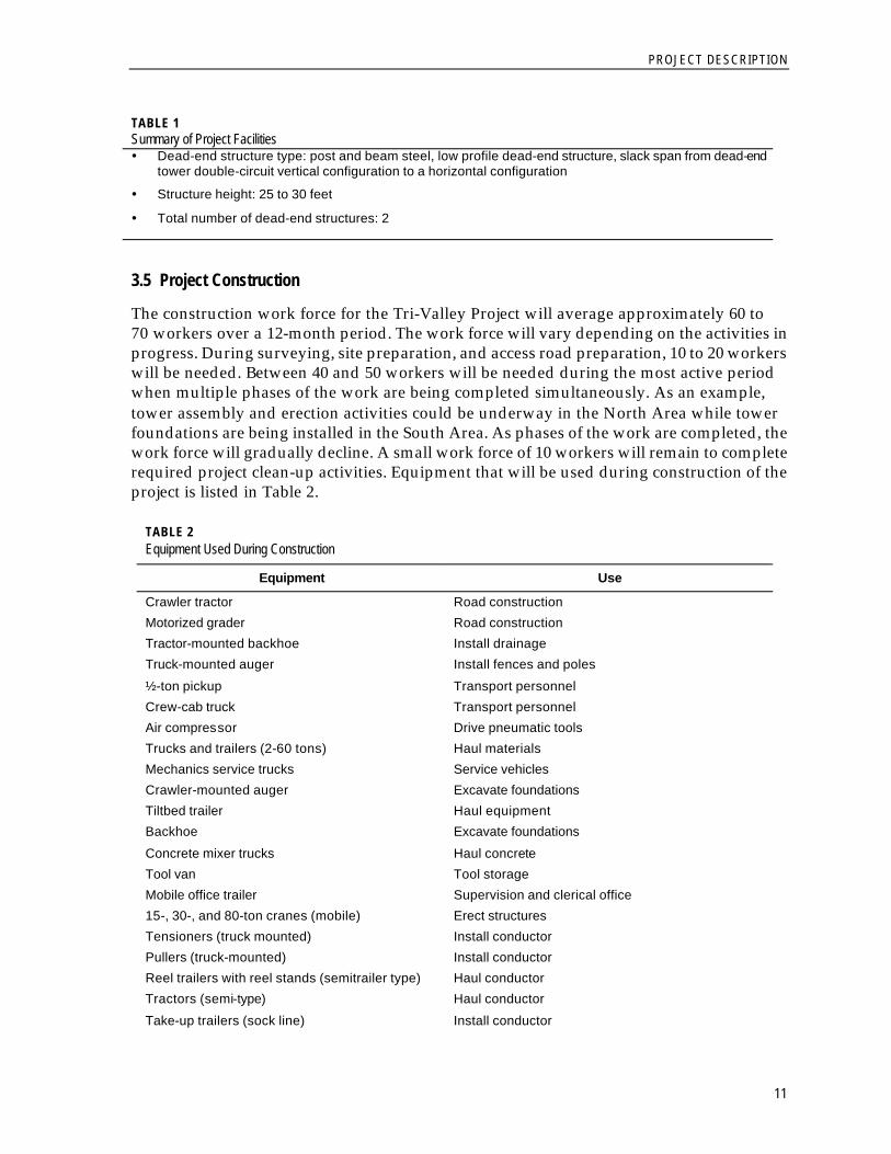
TABLE 1 Summary of Project Facilities � Dead-end structure type: post and beam steel, low profile dead-end structure, slack span from dead-end
tower double-circuit vertical configuration to a horizontal configuration
� Structure height: 25 to 30 feet
� Total number of dead-end structures: 2
3.5 Project Construction
The construction work force for the Tri-Valley Project will average approximately 60 to 70 workers over a 12-month period. The work force will vary depending on the activities in progress. During surveying, site preparation, and access road preparation, 10 to 20 workers will be needed. Between 40 and 50 workers will be needed during the most active period when multiple phases of the work are being completed simultaneously. As an example, tower assembly and erection activities could be underway in the North Area while tower foundations are being installed in the South Area. As phases of the work are completed, the work force will gradually decline. A small work force of 10 workers will remain to complete required project clean-up activities. Equipment that will be used during construction of the project is listed in Table 2.
TABLE 2 Equipment Used During Construction
Equipment Use
Crawler tractor Road construction Motorized grader Road construction Tractor-mounted backhoe Install drainage Truck-mounted auger Install fences and poles
½-ton pickup Transport personnel Crew-cab truck Transport personnel Air compressor Drive pneumatic tools Trucks and trailers (2-60 tons) Haul materials Mechanics service trucks Service vehicles Crawler-mounted auger Excavate foundations Tiltbed trailer Haul equipment Backhoe Excavate foundations
Concrete mixer trucks Haul concrete Tool van Tool storage Mobile office trailer Supervision and clerical office 15-, 30-, and 80-ton cranes (mobile) Erect structures Tensioners (truck mounted) Install conductor Pullers (truck-mounted) Install conductor Reel trailers with reel stands (semitrailer type) Haul conductor Tractors (semi-type) Haul conductor
Take-up trailers (sock line) Install conductor
PROJECT DESCRIPTION
12
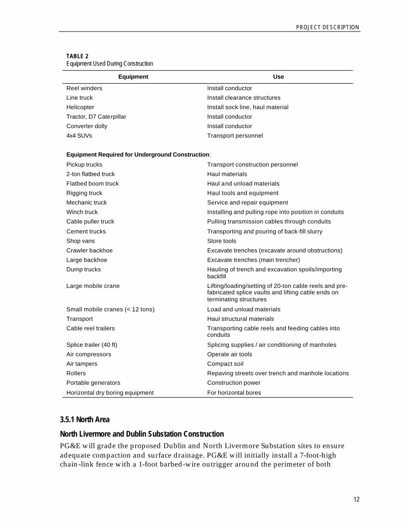
TABLE 2 Equipment Used During Construction
Equipment Use
Reel winders Install conductor Line truck Install clearance structures Helicopter Install sock line, haul material Tractor, D7 Caterpillar Install conductor Converter dolly Install conductor 4x4 SUVs Transport personnel Equipment Required for Underground Construction:
Pickup trucks Transport construction personnel 2-ton flatbed truck Haul materials Flatbed boom truck Haul and unload materials Rigging truck Haul tools and equipment Mechanic truck Service and repair equipment Winch truck Installing and pulling rope into position in conduits Cable puller truck Pulling transmission cables through conduits
Cement trucks Transporting and pouring of back-fill slurry Shop vans Store tools Crawler backhoe Excavate trenches (excavate around obstructions) Large backhoe Excavate trenches (main trencher) Dump trucks Hauling of trench and excavation spoils/importing
backfill Large mobile crane Lifting/loading/setting of 20-ton cable reels and pre-
fabricated splice vaults and lifting cable ends on terminating structures
Small mobile cranes (< 12 tons) Load and unload materials Transport Haul structural materials Cable reel trailers Transporting cable reels and feeding cables into
conduits
Splice trailer (40 ft) Splicing supplies / air conditioning of manholes Air compressors Operate air tools Air tampers Compact soil Rollers Repaving streets over trench and manhole locations Portable generators Construction power
Horizontal dry boring equipment For horizontal bores
3.5.1 North Area
North Livermore and Dublin Substation Construction PG&E will grade the proposed Dublin and North Livermore Substation sites to ensure adequate compaction and surface drainage. PG&E will initially install a 7-foot-high chain-link fence with a 1-foot barbed-wire outrigger around the perimeter of both
PROJECT DESCRIPTION
13
substations to provide security and protect the public from contacting the high-voltage equipment.
Reinforced concrete footings and slabs will be constructed to support structures and equipment. PG&E will install buried conduit throughout the substation site for electrical control cables. After the trenches are dug, conduit will be placed on a bed of sand, and then soil will be backfilled and compacted to match the adjacent grade.
PG&E will install a grounding mat approximately 18 inches below the substation soil grade to protect workers from electrical shock in the event of a ground fault. Trenches will be dug in both directions across the station, and copper conductors will be installed, creating a grounding mat across the entire substation. Soil will be backfilled and compacted to match the adjacent grade. Gravel or crushed rock will be installed over the substation to a depth of approximately 4 inches to provide electrical isolation for workers in the substation.
Structures will be erected to support switches, electrical conductors, instrument transformers, and other electrical equipment, as well as to terminate incoming and outgoing power lines. PG&E will use fabricated tubular steel structures. Structures within the substation will be grounded to the station grounding grid. Workers will set all equipment on slabs and footings, and will either bolt or weld the equipment securely to meet seismic requirements.
230 kV Transmission Line
Right-of-Way Requirements An easement of between 100 to 120 feet wide is required for 230 kV double-circuit transmission lines. The width depends on the lateral distance between the conductors, swing of the conductors caused by wind, and the distance specified by the CPUC's General Order 95 related to safe conductor clearances.
Construction Methods The procedures for bringing personnel, materials, and equipment to each structure site, constructing the supporting structure foundations, erecting the supporting structure, and stringing the conductors will vary along the route alignment. PG&E will construct the transmission line in the following four steps:
• Step 1—Site Access Preparation. PG&E will use temporary laydown areas approximately 2 acres in size for constructing the proposed 230 kV transmission line. The North Livermore and Dublin Substation sites will be used as transmission line material laydown areas. Each site is 5 acres in size. This eliminates the need to impact any additional areas along the route.
PG&E would construct approximately 7.9 miles of overhead transmission line in the North Area. The area to be traversed is primarily used for cattle grazing, and although it is somewhat remote, there is a developed road network used by property owners for managing their cattle operations. Construction equipment will be able to travel on approximately 4.8 miles of existing farm road, but may need to use cross-country routes (over grassland) in the dry season for approximately 4 miles. Some existing roads may need to be improved and/or widened to allow equipment access. All material removed for this purpose would be compacted in the existing roadway. Grades in excess of
PROJECT DESCRIPTION
14
15 percent will be evaluated to determine whether aggregate base (gravel) would be required (with the landowner’s approval) to improve vehicle traction.
Less than 1 mile of new all-weather (gravel) road, approximately 12 feet wide, would need to be constructed to provide access to some sites. Most of the new road construction is a half-mile segment necessary to connect the proposed Dublin Substation site to an existing county road.
Access roads will be maintained when required for operation and/or maintenance of the transmission facilities; otherwise, the land will be restored to its original condition. In accordance with proposed mitigation measures to protect biological resources, PG&E will flag and avoid areas determined to be environmentally sensitive.
• Step 2—Installing the Supporting Structure Foundations. PG&E will install drilled pier foundations at each structure site in the North Area. Material removed during the process will be placed in a location specified by the landowner and/or disposed of according to all applicable laws. Temporary disturbance around each structure site will be limited to a 100-foot radius around the foundation. Disturbance will consist of soil compaction from placement of crane outrigger pads and from vehicle tracks. If necessary, restoration of the area will include reseeding according to landowner instructions. However, most of the area will return to pre-existing conditions after the first spring rain season.
- Lattice Steel Towers. Placement of lattice steel towers will require boring four holes, one for each structure leg. Each hole will be about 4 feet in diameter and 11 to 15 feet deep. Workers will place reinforcing steel in each hole along with stub angles, which formulate part of the tower leg itself. Concrete forms that reach up to 2 or 3 feet above natural ground level will be placed over each hole, and concrete will be placed around the reinforcing steel and stub angles up to the top of the form.
- Tubular Steel Poles. Placement of tubular steel pole structures will require the use of a large auger to dig the foundation hole. The foundation hole will be between approximately 5 feet and 7 feet in diameter and from 15 to 30 feet deep. A rebar cage with anchor bolts will be installed and concrete will be placed in the hole. During the concrete curing period of 1 month, workers will remove the concrete forms and place backfill around the foundations.
• Step 3—Erecting the Supporting Structures.
- Lattice Steel Towers. The double-circuit lattice steel towers will have three cross arms, each supporting two phases consisting of a single conductor on each side. Steel tower components, packaged in bundles by tower type, will be dispatched to each tower site. Individual towers will be assembled immediately adjacent to the tower foundations and raised into place using a large crane. A smaller crane will also be used to assemble tower sections and to lift heavy steel members into place during assembly. After the structure is set on the foundation, crews will tighten all bolts to specified torques, attach insulators to the crossarms, and prepare the towers for the conductor stringing operation.
PROJECT DESCRIPTION
15
- Tubular Steel Poles. The double-circuit tubular steel pole structures will also have three cross arms, each supporting a phase conductor on each side of the cross arm. The pole shafts will be delivered to the site in two or more sections. For safety and ease of construction, the poles will be assembled on the ground. The sections will be pulled together with a winch and the cross arms bolted to the pole. Insulators will be attached to the cross arms and secured. A large crane will erect the poles and set them on the anchor bolts embedded in the concrete foundation. Finally, the securing nuts on the foundation will be tightened.
• Step 4—Conductor Stringing. Before conductor installation begins, temporary clearance structures will be installed at road crossings and other locations where the new conductors may accidentally come in contact with electrical or communication facilities and/ or vehicular traffic during installation. PG&E will use a set of temporary clearance structures at all roads and railroad crossings, and at all other power lines. These structures will be placed at the edge of the roadway and will not require grading. Conductor installation preparation activities require locating pull and tension sites at 2- to 3-mile intervals. These sites will be approximately 1 acre in size.
The conductor stringing operation begins with installation of insulators and sheaves or stringing blocks. The sheaves are rollers attached to the lower end of the insulators that are, in turn, attached to the ends of each supporting structure cross arm. The sheaves allow the individual conductors to be pulled through each structure until the conductors are ready to be pulled up to the final tension position.
When the pull and tension equipment is set in place, a sock line (a small cable used to pull in the conductor) is pulled from tower to tower using helicopters to place the sock line into the sheaves. After the sock line is installed, the conductors are attached to the sock line and pulled in or “strung” using the tension stringing method. This involves pulling the conductor through each tower under a controlled tension to keep the conductors elevated above crossing structures, roads, and other facilities.
After the conductors are pulled into place, wire or conductor sags are adjusted to a pre-calculated level. The conductors are then clamped to the end of each insulator as the sheaves are removed. The final step of the conductor installation is to install vibration dampers and other accessories. The temporary crossing structures would be removed at this time.
Packing crates, loose bolts, and construction debris will be picked up and hauled away for recycling or disposal during construction. PG&E will conduct a final survey to ensure that cleanup activities have been successfully completed as required.
Distribution System 21 kV Wood Pole Installation. Placement of wood poles for the 21 kV distribution lines from North Livermore and Dublin Substations will require the use of an auger to dig the hole for the pole. The hole will be approximately 3 feet in diameter by 9 feet deep. The wood poles will be delivered to the site and the insulators and cross arms bolted to the poles. The poles will be assembled on the ground both for ease of construction and safety. The assembled poles will be lifted into the air with a line truck, set in the hole, and then backfilled.
PROJECT DESCRIPTION
16
21 kV Circuit Underground Installation. The 21 kV distribution system consists of underground electrical cables, conduits, substructures, subsurface equipment, and pad-mounted equipment. Underground electric facilities will be installed within the road easements as needed to serve existing and future customers. The conduits (duct) would be
installed in a trench approximately 3 feet wide and 8 feet deep. The conduit would have a minimum cover of 36 inches.
Conductor Installation. For overhead conductor installation, a steel cable is fed through stringing sheaves at the end of each insulator. The cable is then attached to the conductor and the conductor is pulled off the reels through a tensioner and strung to the other end.
3.5.2 South Area
Vineyard Substation Modification New structures in the Vineyard Substation will be developed within the existing fenced area. Reinforced concrete footings and slabs will be constructed to support structures and equipment. PG&E will extend the existing buried conduit installation to cover the expanded area for the electrical control and communication cables. PG&E will extend the existing grounding mat to cover the modified area and install gravel over the new area to match the existing gravel level.
Structures will be erected to support busses, circuit breakers, switches, overhead conductors, instrument transformers and other electrical equipment, as well as to terminate incoming transmission lines. PG&E will use fabricated tubular steel structures. Structures within the substation will be grounded to the station grounding grid. Workers will set the equipment on slabs and footings, and will either bolt or weld the equipment securely to meet the applicable seismic requirements. Equipment slated for installation includes high-voltage circuit breakers and air switches, structures and bus work, high-voltage instrument transformers and line traps, control and power cables, metering, relaying, and communication equipment.
230 kV Overhead Transmission Line The procedures for bringing personnel, materials, and equipment to each structure site, constructing the supporting structure foundations, erecting the supporting structure, and stringing the conductors will vary along the route alignment. PG&E will construct the transmission line in four steps as described for the North Area transmission line. Transmission line materials will be stockpiled on General Electric property through a land rental agreement. Sufficient paved area exists on this property and no natural ground disturbance would be necessary. To construct the overhead portion of the South Area transmission line (approximately 2.8 miles), PG&E would construct approximately 0.8 miles of new all-weather (gravel) road. Construction vehicles would use 3 miles of an existing farm road and drive cross country over 0.8 miles of grazing land.
230 kV Underground Transmission Line Construction Methods The duct bank containing the solid dielectric cables would be installed in a trench approximately 3 feet wide and 8 feet deep. The duct bank would have a minimum cover of
PROJECT DESCRIPTION
17
32 inches. Approximately every 1,500 feet, splice vaults would be incorporated for installing cables and splicing sections of cables together. Each circuit would be capable of carrying 400 MVA per circuit at the normal conductor rating of 90 degrees centigrade. Cables would rise out of the ground at the transition station and at the Vineyard Substation, and they would terminate on support structures.
Approximately 2.7 miles of underground 230 kV double-circuit transmission line would be installed from Milepost 2.8 to the Vineyard Substation. The work would be completed using cut and cover construction (open trenching) of the underground power line, conduits, and duct banks.
Soil sampling and potholing will be conducted before construction. Soil information will be provided to construction crews to inform them about soil conditions and utility locations. If hazardous materials are encountered in soils from the trench, work will be stopped until the material is properly characterized and appropriate measures are taken to protect human health and the environment. Hazardous materials will be handled, transported, and disposed of in accordance with federal, state, and local environmental regulations, including Chapter 6.95 of the California Health and Safety Code and Title 22 of the California Code of Regulations.
Standard erosion and dust control measures will be used during construction. These methods include installation of sediment and erosion control structures according to best management practices (BMPs) to protect biological resources, roadways, and adjacent properties. Watering for dust control will also be employed.
Temporary lane closures along residential streets as required for underground construction would be coordinated with the City of Pleasanton as described in Chapter 11, Transportation/ Traffic. PG&E is a member of the California Joint Utility Traffic Control Committee, which in 1996 published the Work Area Protection and Traffic Control Manual. The traffic control plans and associated text depicted in this manual conform to the guidelines established by the Federal and State Departments of Transportation. PG&E will follow the recommendations in this manual regarding basic standards for the safe movement of traffic upon highways and streets in accordance with Section 21400 of the California Vehicle Code. These recommendations include provisions for safe access of police, fire, and other rescue vehicles. In addition, PG&E will obtain roadway encroachment permits from the City of Pleasanton and will submit a traffic management plan subject to agency review and approval.
To construct the transition station, provide year-round maintenance access, and protect the underground cableway from accidental dig-ins, PG&E proposes to construct 0.4 mile of new roadway over the underground cable. This new road will connect the transition station to the existing access road leading to the water tank above Benedict Court. The water tank access road, approximately 0.4 mile long, would be used to install the remaining segment of underground cable before reaching city streets. The remaining length of underground cable will be installed within City of Pleasanton streets per the existing city franchise agreement.
Horizontal Dry Boring. Because open trenching through Arroyo Valle Creek is not desirable, horizontal dry boring will be used for underground construction at the Bernal Avenue Bridge. Up to two steel casings between 30 and 42 inches in diameter will be installed under
PROJECT DESCRIPTION
18
the creek at least 5 feet below the creek bed or as required by the permitting agency. The dry boring operation under the creek would begin at the north end of the bridge in an underground easement area leading to the Vineyard Substation. An area approximately 25 feet by 100 feet would be used at this location for laydown and boring. A shored trench of approximately 20 feet deep would be used as a receiving area for the bore casing. The bore would be approximately 5 feet below the creek bed and approximately 15 feet below Bernal Avenue.
Dry boring would begin by digging a bore pit at the sending end and a trench at the receiving end of the bore. The bore pit would be approximately 24 feet by 8 feet wide and would be approximately 20 feet deep. The elevation at the bottom of the bore pit and the receiving trench would be about the same. The horizontal bore equipment would then be installed in the bore pit. The steel casing would be welded in 10- to 15-foot sections and jacked into the bore as the boring operation proceeds.
The actual volume of soil removed from the creek bore is estimated to be approximately 100 cubic yards. All spoils and asphalt would be loaded straight from the bore area onto trucks for removal. At no time would spoils be stored on site. In addition to the boring machinery, a loader, backhoe, and dump truck would be used at both ends of the bore.
The racked PVC conduit bundles would be arranged in a circular pattern. The conduit bundles would be assembled completely before being pulled through the steel casing. Once boring is complete, the trench would be extended to meet the exposed cable at the south end of the bridge where the conduits would be joined together.
The setup for the dry boring operation would require a crew of four, while the operation of the bore would only require two or three crew members. The duct pull would require a crew of four to six. The length of time estimated for completing the bore is 3 weeks.
Construction Activities. The major construction activities associated with installation of underground cable are as follows:
• Saw cut the pavement for the trench and splice vaults
• Excavate a trench for the electrical conduit bank
• Haul away and dispose of trenched and excavated spoils
• Install the cable conduit, reinforcement bar, ground wire, and concrete conduit encasement (duct bank)
• Excavate and place pre-formed concrete splice vaults
• Backfill the trench
• Pull cable into the conduit bank and splice at several predetermined locations (vaults) along the route
• Terminate cables at Vineyard Substation and at transition structures
• Horizontal bore of one or two steel casings under Arroyo Valle Creek near Bernal Avenue
PROJECT DESCRIPTION
19
• Restore all paved surfaces, restore landscaping as necessary, and clean up the job site
Vehicles and Equipment. A dump truck would be on site during excavation activities. As trucks are filled with spoils, they would leave the site and be replaced by empty trucks. The number of truck trips per day would depend upon the rate of the trenching and the size of vault excavation. Jackhammers would be used sparingly to break up any sections of concrete that cannot be reached with the saw-cutting and pavement-breaking machines. Other miscellaneous equipment would include a concrete saw, a pavement breaker, various paving equipment, and pickup trucks.
Trenching. To construct the underground duct bank, the roadway would be temporarily trenched. The width of the work space will be as set forth in the encroachment permit to be issued by the City of Pleasanton. The typical trench would be approximately 3 feet wide, with a depth of 6 to 8 feet. A maximum open trench length of 600 feet on each street would be typical at any one time, with provisions for emergency vehicle and local access. Additionally, the trench would be wider or shored where needed to meet Cal/OSHA safety requirements. Prior to trenching, PG&E will notify other utility companies (via the Underground Service Alert or USA) to locate existing underground structures along the proposed alignment.
After the trench route is marked and encroachment permits are obtained, work begins with a concrete saw cutting the trench line. The trench pavement would be broken into manageable pieces for removal and the trench dug to a depth of 6 to 8 feet. At about 12 points along the trench, larger excavations would be opened to install splice vaults. Throughout construction, asphalt, concrete, and spoils would be hauled off by truck to an approved Class III disposal site. Approximately 11,000 cubic yards of asphalt and spoil would be removed, resulting in approximately 1,100 truck trips during excavation.
Vaults. Approximately 26 underground vaults (13 per circuit) would be installed during trenching for pulling cables and housing cable splices. The vaults would be used initially to pull the cables through the conduits and to splice cables together. During operation, vaults provide access to the underground cables for maintenance inspections and repairs. Vaults would be constructed of steel-reinforced concrete (either prefabricated or cast-in-place), with inside dimensions of approximately 18 feet long, 5 feet wide, and 8 feet deep. The vaults would be designed to withstand the maximum credible earthquake in the area, as well as heavy truck traffic loading.
The vaults will be installed in pairs placed end-to-end and overlapping in order to separate circuits into respective vaults. The circuits are spliced in separate vaults in order for maintenance workers to work safely on a de-energized circuit while the second circuit remains energized. An electrical fault from an energized splice or cable inside of a vault could injure or be fatal to a worker. The total excavation footprint for the pair of vaults would be approximately 40 feet long by 15 feet wide. Installation of each vault would take place over a 3-day period with excavation and shoring of the vault pit being followed by delivery and installation of both vaults, filling and compacting a backfill, and repaving of the excavation area.
Equipment Installation. Following trench excavation, nine 6-inch PVC conduits would be racked in a three-by-three arrangement. The underground cables would then be contained
PROJECT DESCRIPTION
20
within the 6-inch PVC conduit pipes, which themselves would be housed in reinforced concrete duct banks. The 400 MVA load on this circuit would be met using approximately 2500-kcmil copper conductor extruded dielectric (XLPE) cable. To achieve this performance, both circuits would be installed in a common duct bank, with special cross-bonding of cable sheaths to reduce heat generated by sheath losses. When the electrical transmission duct bank crosses or runs parallel to other substructures (which have operating temperatures not exceeding basal earth temperature), a minimum radial clearance of 12 inches is required from these substructures. These types of substructures include electric lines, telephone lines, water mains, storm lines, and sewer lines. In addition, a 5-foot minimum radial clearance is required when the new electrical transmission duct bank crosses another heat-radiating substructure at right angles. A 15-foot minimum radial clearance is required between the electrical transmission duct bank and any paralleling substructure whose operating temperature significantly exceeds the normal earth temperature. Examples of heat radiating facilities are additional underground transmission circuits, primary distribution cables (especially multiple-circuit duct banks), steam lines, or heated oil lines.
The majority of the route will be in the three-by-three duct bank configuration with occasional rolling of ducts into a flat configuration in order to clear substructures in highly congested areas or to fan out to termination structures. The main duct bank will split into two separate duct banks leading into each splice vault.
Backfilling and Paving. Once the duct bank is installed, thermal-select or controlled backfill will be imported, installed, and compacted. A road base back-fill or slurry concrete cap would then be installed, and the road surface would be restored in compliance with the locally issued permits. While the completed trench line sections are being restored, additional trench line would be opened further down the street. This process would continue until the entire conduit system is in place.
Cable Installation and Splicing. Cable will be pulled through individual ducts at the rate of approximately two pulls per day. After cable installation is completed, the cables will be spliced between all vaults and riser structures. A splice trailer would be located directly above the manhole openings for easy access by workers. A mobile power generator would be located directly behind the trailer. The dryness of the vault must be maintained 24 hours per day to ensure that unfinished splices are not contaminated with water or impurities. Normal splicing hours would be 8 to 10 hours per day with some workers remaining after hours to maintain splicing conditions and guard against vandalism and theft. These conditions are essential to maintaining quality control through completion of splicing. As splicing is completed at a vault, the splicing apparatus setup is moved to the next vault location and the splicing is resumed.
Construction Duration The length of time required for constructing this phase of the project is approximately 13 months. Trenching, installation of the concrete duct bank, and vault installation would be completed within 5 months, while cable installation, splicing, and terminating would require approximately 6 months. Underground construction will require approximately 10 to 20 crew members.
PROJECT DESCRIPTION
21
Right-of-Way Requirements In undeveloped property, the conduit will be placed in the center of a 30-foot easement (to be acquired) that can be placed within a future roadway system. PG&E will restrict any above ground structure or foundation within the easement. Deep rooted vegetation that could compromise the integrity of the electric system will also be restricted. The easement language will require the property owner to notify PG&E should any change in the overburden depth be contemplated. This is necessary to ensure public safety and system integrity. In developed areas, the underground portion of the transmission line will be placed in city streets and will comply with City of Pleasanton franchise agreements.
3.6 Service Interruption During Construction The following actions will be taken to avoid service interruptions:
• Customers will receive electricity from alternative sources where feasible
• Temporary distribution connections and construction may be implemented to maintain service during construction
3.7 Operation and Maintenance Procedures
General System Monitoring and Control Substation monitoring and control functions will be connected to the Newark Switching Center and the Hayward Distribution Operations computer system by a telecommunication circuit. Protective relay communication will be through a power line carrier system.
Facility Inspection The regular inspection of transmission lines, instrumentation and control, and support systems is critical for safe, efficient, and economical operation. Early identification of items needing maintenance, repair, or replacement will ensure continued safe operation of the project. PG&E will inspect all of the structures from the surface annually for corrosion, misalignment, and excavations. Ground inspection will occur on selected lines to check the condition of hardware, insulators, and conductors. This inspection will include checking conductors and fixtures for corrosion, breaks, broken insulators, and failing splices.