Embed Size (px)
Citation preview

PROJECT MANUAL
North Terminal Development Program Phase 1
Construction Documents 100%
Volume #12 (LADOTD and Jefferson Parish Standards)
NOAB PROJECT # 8910-01233
CNO SOLICITATION # xxx-xxxxx
June 30, 2015
LOUIS ARMSTRONG NEW ORLEANS INTERNATIONAL AIRPORT
KENNER, LOUISIANA
FOR THE
NEW ORLEANS AVIATION BOARD
Sponsored By:
CITY OF NEW ORLEANS NEW ORLEANS AVIATION BOARD
Mayor: Mitchell J. Landrieu Chairwoman: Cheryl Teamer
Director of Aviation
Iftikhar Ahmad
Council Members Members of the Board Stacey S. Head Cheryl Teamer (Chairwoman)
Susan G. Guidry Doug Thornton (Vice-Chairman)
Nadine Ramsey Michael Smith
James Austin Gray II Ti Martin
Jason Rogers Williams Lea Polk Montgomery
LaToya Cantrell Roger H. Ogden
Jared C. Brossett Todd Francis
Gary Smith, Sr.
Jim Hudson
Technical Specifications and Drawings Prepared by: Crescent City Aviation Team

THIS PAGE INTENTIONALLY LEFT BLANK

Louis Armstrong New Orleans International Airport NOAB Project # 8910-01233
North Terminal Development Program Phase 1 City of New Orleans Solicitation XXX-XXXXX
Construction Documents Seal Pages 00 01 07 - Page 1 of 24
100% - 6/30/15
SEAL AND SIGNATURE BY DESIGN PROFESSIONAL:
ARCHITECTURAL:
Architect of Record: Stephen C. Wright, AIA, Leo A. Daly
Applicable Sections:
01 21 00 Allowances 01 22 00 Unit Prices
01 23 00 Alternates
01 40 00 Mockups 01 73 00 Cutting and Patching
02 41 16 Structure Demolition
02 41 19 Selective Demolition 04 20 00 Unit Masonry
05 40 00 Cold Formed Metal Framing
05 50 00 Metal Fabrications 05 51 13 Metal Pan Stairs
05 51 19 Metal Grating Stairs
05 52 13 Tube Railings 05 58 19 Heating-Cooling Unit Cover
05 73 13 Glazed Decorative Metal Railings
05 75 00 Decorative Formed Metal
06 10 00 Rough Carpentry
06 16 00 Sheathing 06 26 00 Sculptural Wall Panels
06 41 16 Architectural Millwork
07 11 13 Bituminous Dampproofing 07 14 16 Cold Fluid-Applied Waterproofing
07 16 16 Crystalline Waterproofing
07 21 00 Thermal Insulation 07 24 13 Polymer-Based Exterior Insulation and
Finish System (EIFS)
07 27 26 Fluid-Applied Membrane Air-Barriers
07 42 00 Metal Composite Material Panels
07 42 12 Metal Soffit Panels
07 42 13 Formed Metal Wall Panels 07 42 14 Insulated Metal Wall Panels
07 54 19 Polyvinyl-Chloride (PVC) Roofing
07 62 00 Sheet Metal Flashing and Trim 07 71 00 Roof Specialties
07 72 00 Roof Accessories
07 81 00 Applied Fireproofing 07 81 23 Intumescent Fireproofing
07 84 13 Penetration Firestopping
07 84 43 Joint Firestopping
07 91 00 Preformed Joint Seals
07 92 00 Joint Sealants
07 92 19 Acoustical Joint Sealants 07 95 00 Expansion Control
08 11 13 Hollow Metal Doors and Frames
08 14 16 Flush Wood Doors 08 31 13 Access Doors and Frames
08 33 23 Overhead Coiling Doors
08 34 73 Sound Control Door Assemblies 08 35 13 Accordion Folding Fire Doors
08 41 13 Aluminum-Framed Storefronts
08 42 13 Aluminum-Framed Entrances 08 42 29 Sliding Automatic Entrances
08 44 13 Glazed Aluminum Curtain Walls
08 44 23 Structural-Sealant Glazed Curtain Walls 08 44 29 Specialty Curtain Wall Systems
08 45 19 Structural Polycarbonate Canopy
System 08 45 23 Fiberglass-Sandwich Panel Assemblies
08 56 53 Security Windows 08 63 00 Specialty Skylight Systems
08 71 00 Door Hardware
08 80 00 Glazing 08 83 00 Mirrors
08 91 13 Motorized Glass Louver Ventilator
System 08 91 19 Fixed Louvers
09 21 16 Gypsum Board Shaft Wall Assemblies
09 22 16 Non-Structural Metal Framing
09 26 13 Gypsum Veneer Plastering
09 29 00 Gypsum Board
09 30 13 Ceramic Tiling 09 51 13 Acoustical Panel Ceilings
09 51 23 Acoustical Tile Ceilings
09 51 33 Acoustical Metal Pan Ceilings 09 54 23 Linear Metal Ceilings
09 64 00 Wood Flooring
09 65 13 Resilient Base 09 65 19 Resilient Tile Flooring
09 66 23 Resinous Matrix Terrazzo Flooring
09 67 23 Resinous Flooring
09 68 13 Tile Carpeting
09 72 00 Wall Coverings
09 91 13 Exterior Painting 09 91 23 Interior Painting
09 96 00 High-Performance Coatings
09 96 53 Elastomeric Coatings 09 96 56 Epoxy Coatings
09 97 26 Concrete Sealers
10 11 00 Visual Display Units 10 12 00 Information Display Systems
10 14 13 Panel Signage
10 21 13 Stainless Steel Toilet Compartments 10 22 39 Folding Glass-Panel Partitions
10 26 00 Wall and Door Protection
10 28 00 Toilet Accessories 10 43 13 Defibrillator Cabinets
10 44 13 Fire Protection Cabinets
10 44 16 Fire Extinguishers 10 55 00 USPS-Delivery Postal Specialties
10 80 00 Miscellaneous Specialties 11 13 13 Loading Dock Bumpers
11 31 00 Residential Appliances
11 53 13 Laboratory Fume Hoods 12 36 61 Simulated Stone Countertops
12 48 13 Entrance Floor Mats
12 65 00 Hold Room Seating 12 67 23 Interior Wood Bench
13 00 00 Bullet Resistant Fiberglass Panels
13 30 00 Tensile Membrane Ceiling Systems
13 34 19 Metal Building Systems
14 21 00 Electric Traction Elevators
14 21 13 Electric Traction Freight Elevators 14 24 00 Hydraulic Elevators
14 31 00 Escalators
14 91 82 Trash Chutes 26 51 19 Architectural Luminaires, Lamps,
Ballasts
31 31 16 Termite Control 32 31 13 Interior Chain Link Fences and Gates
34 77 14 Fixed Walkways
34 77 39 Baggage Conveying Equipment


NOAB Project # 8910-01233 Louis Armstrong New Orleans International Airport
City of New Orleans Solicitation XXX-XXXXX North Terminal Development Program Phase 1
00 01 07 - Page 8 of 24 Seal Pages Construction Documents
100% - 6/30/15
SEAL AND SIGNATURE BY DESIGN PROFESSIONAL:
MECHANICAL (SHG)
Engineer of Record: Christopher John Wescott, PE, Syska Hennessy Group
Applicable Sections:
23 05 00 Common Work Results For HVAC
23 05 13 Common Motor Requirements for HVAC Equipment
23 05 16 Expansion Fittings and Loops for HVAC Piping
23 05 19 Meters and Gages for HVAC Piping
23 05 23.11 Globe Valves for HVAC Piping
23 05 23.12 Ball Valves for HVAC Piping
23 05 23.13 Butterfly Valves for HVAC Piping
23 05 23.14 Check Valves for HVAC Piping
23 05 23.15 Gate Valves for HVAC Piping
23 05 23.16 Plug Valves for HVAC Piping
23 05 29 Hangers and Supports for HVAC Piping and Equipment
23 05 33 Heat Tracing For HVAC
23 05 48 Vibration Controls For HVAC
23 05 53 Identification for HVAC Piping and Equipment
23 05 93 Testing, Adjusting, and Balancing For HVAC
23 07 13 Duct Insulation
23 07 16 HVAC Equipment Insulation
23 07 19 HVAC Piping Insulation
23 09 00 Instrumentation and Control for HVAC
23 09 20 Refrigerant Detection and Alarm
23 21 13 Hydronic Piping
23 21 16 Hydronic Piping Specialties
23 21 23 Hydronic Pumps
23 23 00 Refrigerant Piping
23 25 00 HVAC Water Treatment
23 29 23 Variable Frequency Motor Controllers
23 31 13 Metal Ducts
23 31 19 HVAC Casings
23 33 00 Air Duct Accessories
23 34 13 Axial HVAC Fans
23 34 16 Centrifugal HVAC Fans
23 34 33 Air Curtains
23 36 00 Air Terminal Units
23 37 13 Diffusers, Registers, and Grilles
23 41 00 Particulate Air Filtration
23 51 00 Breechings, Chimneys, and Stacks
23 51 13 Draft Control Devices
23 52 16 Condensing Boilers
23 57 00 Heat Exchangers for HVAC
23 64 16 Centrifugal Water Chillers
23 65 00 Cooling Towers
23 72 00 Air-To-Air Energy Recovery Equipment
23 73 13 Modular Indoor Central-Station Air-Handling Units
23 74 33 Dedicated Outdoor Air Units
23 81 23 Computer-Room Air-Conditioners
23 81 26 Split-System Air-Cooled Air Conditioners and Heat
Pumps
23 82 16 Air Coils
23 82 19 Fan Coil Units
23 82 33 Convectors
23 82 39 Unit Heaters
23 83 16 Radiant Cooling and Heating Hydronic Piping
33 61 13 Underground Hydronic Energy Distribution

Louis Armstrong New Orleans International Airport NOAB Project # 8910-01233 North Terminal Development Program Phase 1 City of New Orleans Solicitation XXX-XXXXX
Construction Documents Seal Pages 00 01 07 - Page 11 of 24 100% - 6/30/15
SEAL AND SIGNATURE BY DESIGN PROFESSIONAL:
COMMUNICATIONS AND SECURITY (RBA)
Engineer of Record: Gregory Scott Spence, PE, Ross & Baruzzini
Applicable Sections:
27 01 00 General Requirements for Communications Systems 27 05 00 Common Work Results for Communications Systems 27 05 26 Grounding and Bonding for Communications Systems 27 05 28 Pathways for Communications Systems 27 05 36 Cable Trays for Communications Systems 27 05 53 Identification for Communications Systems 27 07 90 Local Area Network 27 11 00 Communications Equipment Room Fittings 27 13 00 Communications Backbone Cabling 27 15 00 Communications Horizontal Cabling 27 42 16 Electronic Visual Information Display System 27 51 16 Public Address System 27 53 16 Commercial Lane RFID System 28 05 00 General Security Systems Requirements 28 13 00 Security and Access Control System 28 23 00 Video Surveillance Systems


NOAB Project # 8910-01233 Louis Armstrong New Orleans International Airport City of New Orleans Solicitation XXX-XXXXX North Terminal Development Program Phase 1
00 01 07 - Page 20 of 24 Seal Pages Construction Documents 100% - 6/30/15
SEAL AND SIGNATURE BY DESIGN PROFESSIONAL:
CIVIL:
Engineer of Record: Manuel O. Bejarano, PE, Atkins North America Applicable Sections:
FAA P-101 Surface Preparation FAA P-152 Excavation, Subgrade, and Embankment FAA P-153 Controlled Low-Strength Material (CLSM) FAA P-159 Cement Modified Subgrade FAA P-160 Low Density Cellular Concrete (LDCC) FAA P-209 Crushed Aggregate Base Course FAA P-304 Cement-Treated Base Course FAA P-401 Hot Mix Asphalt (HMA) Pavement FAA P-501 Portland Cement Concrete (PCC) Pavement FAA P-602 Bituminous Prime Coat FAA P-603 Bituminous Tack Coat FAA P-605 Joint Sealants for Concrete Pavements FAA P-608 Emulsified Asphalt Seal Coat FAA P-610 Structural Portland Cement Concrete LADOTD 301 Class I Base Course LADOTD 502 Superpave Asphaltic Concrete Mixtures LADOTD 503 Asphaltic Concrete Equipment and Processes LADOTD 504 Asphalt Tack Coat LADOTD 505 Asphalt Prime Coat LADOTD 601 Portland Cement Concrete Pavement

Louis Armstrong New Orleans International Airport NOAB Project # 8910-01233 North Terminal Development Program Phase 1 City of New Orleans Solicitation XXX-XXXXX
Construction Documents Seal Pages 00 01 07 - Page 21 of 24 100% - 6/30/15
SEAL AND SIGNATURE BY DESIGN PROFESSIONAL:
CIVIL:
Engineer of Record: Rebecca A. Katzke, PE, CFM Atkins North America
Applicable Sections:
FAA P-156 Temporary Air and Water Pollution, Soil Erosion, and Siltation Control


Louis Armstrong New Orleans International Airport NOAB Project # xxxx-xxxxx
Airport Stormwater Pump Station Intake Canal City of New Orleans Solicitation XXX-XXXXX
Construction Documents Seal Pages 00 01 07- Page 1 of 2
Revision 1 - 7/6/15
SEAL AND SIGNATURE BY DESIGN PROFESSIONAL:
CIVIL
Engineer of Record: James Wilson, PE, LEED AP ® MSMM Engineering, LLC
Applicable Sections:
01 35 13 Special Project Procedures
31 23 19 Dewatering 31 05 19.01 Separator Geotextile
31 05 19.19 Reinforcement Geotextile
FAA P-154 Subbase Course
FAA P-403 Hot Mix Asphalt (HMA) Pavements (Base, Leveling or Surface Course)
NOAB Project # xxxx-xxxxx Louis Armstrong New Orleans International Airport
City of New Orleans Solicitation XXX-XXXXX Airport Stormwater Pump Station Intake Canal
00 01 07 - Page 2 of 2 Seal Pages Construction Documents
Revision 1 - 7/6/15
SEAL AND SIGNATURE BY DESIGN PROFESSIONAL:
STRUCTURAL
Engineer of Record: Robert Yokum, PE, MSMM Engineering, LLC
Applicable Sections:
01 53 00.02 Temporary Retaining Structures (TRS) 05 12 00.01 Structural Steel For Pump Station Intake Canal
05 50 00.01 Miscellaneous Metalwork, Fabricated Items and Standard Articles For Pump Station Intake Canal
31 41 16 Steel Sheet Piling 31 62 16.16 Steel H-Piling

Louis Armstrong New Orleans International Airport NOAB Project # 8910-01233
North Terminal Development Program Phase 1 City of New Orleans Solicitation XXX-XXXXX
Construction Documents Table Of Contents 01 10 00 - Page 1 of 18
Revision 1 - 7/6/15
SECTION 00 10 00 - TABLE OF CONTENTS
This Table of Contents is cumulative. The date associated with each section indicates the date of the lat-
est version of each Specification section issued to date.
VOLUME #1 – CONTRACT REQUIREMENTS
VOLUME #2 – COMMISSIONING REQUIREMENTS
01 91 13 Commissioning Requirements 6/30/15
21 08 00 Commissioning of Fire Suppression 6/30/15
22 08 00 Commissioning of Plumbing 6/30/15
23 08 00 Commissioning of HVAC 6/30/15
26 08 00 Commissioning of Electrical Systems 6/30/15
27 08 00 Commissioning of Communications 6/30/15
28 08 00 Commissioning of Electronic Safety and Security 6/30/15
32 08 00 Commissioning of Exterior Improvements 6/30/15
33 08 00 Commissioning of Utilities 6/30/15
34 08 00 Commissioning of Transportation 6/30/15

NOAB Project # 8910-01233 Louis Armstrong New Orleans International Airport
City of New Orleans Solicitation XXX-XXXXX North Terminal Development Program Phase 1
01 10 00 - Page 2 of 18 Table Of Contents Construction Documents
Revision 1 - 7/6/15
VOLUME #3 – DIVISIONS 01 - 07
DIVISION 01 GENERAL REQUIREMENTS
01 21 00 Allowances Revision 1 - 7/6/15
01 22 00 Unit Prices 6/30/15
01 23 00 Alternates Revision 1 - 7/6/15
01 35 13 Special Project Procedures Revision 1 - 7/6/15
01 40 00 Mockups 6/30/15
01 45 29 Special Testing and Inspections 6/30/15
01 53 00.02 Temporary Retaining Structures (TRS) Revision 1 - 7/6/15
01 73 00 Cutting and Patching 6/30/15
DIVISION 02 EXISTING CONDITIONS
02 41 16 Structure Demolition 6/30/15
02 41 19 Selective Demolition 6/30/15
DIVISION 03 CONCRETE
03 10 00 Concrete Forming and Accessories 6/30/15
03 20 00 Concrete Reinforcing 6/30/15
03 30 00 Cast-In-Place Concrete 6/30/15
03 41 00 Precast Structural Concrete 6/30/15
DIVISION 04 MASONRY
04 20 00 Unit Masonry 6/30/15
DIVISION 05 METALS
05 12 00 Structural Steel Framing 6/30/15
05 12 00.01 Structural Steel for Pump Station Intake Canal Revision 1 - 7/6/15
05 12 10 Secondary Steel Framing 6/30/15
05 15 19 Wire Rope Railings 6/30/15
05 21 00 Steel Joist Framing 6/30/15
05 31 13 Steel Floor Decking 6/30/15
05 31 23 Steel Roof Decking 6/30/15
05 40 00 Cold Formed Metal Framing 6/30/15
05 50 00 Metal Fabrications 6/30/15
05 50 00.01 Miscellaneous Metalwork, Fabricated Items, and Standard Articles
for Pump Station Intake Canal Revision 1 - 7/6/15
05 51 13 Metal Pan Stairs 6/30/15
05 51 19 Metal Grating Stairs 6/30/15
Louis Armstrong New Orleans International Airport NOAB Project # 8910-01233
North Terminal Development Program Phase 1 City of New Orleans Solicitation XXX-XXXXX
Construction Documents Table Of Contents 01 10 00 - Page 3 of 18
Revision 1 - 7/6/15
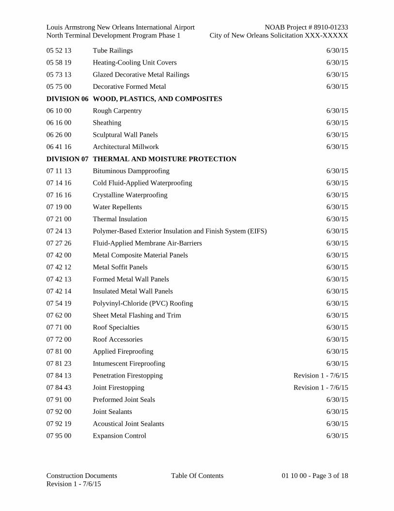
05 52 13 Tube Railings 6/30/15
05 58 19 Heating-Cooling Unit Covers 6/30/15
05 73 13 Glazed Decorative Metal Railings 6/30/15
05 75 00 Decorative Formed Metal 6/30/15
DIVISION 06 WOOD, PLASTICS, AND COMPOSITES
06 10 00 Rough Carpentry 6/30/15
06 16 00 Sheathing 6/30/15
06 26 00 Sculptural Wall Panels 6/30/15
06 41 16 Architectural Millwork 6/30/15
DIVISION 07 THERMAL AND MOISTURE PROTECTION
07 11 13 Bituminous Dampproofing 6/30/15
07 14 16 Cold Fluid-Applied Waterproofing 6/30/15
07 16 16 Crystalline Waterproofing 6/30/15
07 19 00 Water Repellents 6/30/15
07 21 00 Thermal Insulation 6/30/15
07 24 13 Polymer-Based Exterior Insulation and Finish System (EIFS) 6/30/15
07 27 26 Fluid-Applied Membrane Air-Barriers 6/30/15
07 42 00 Metal Composite Material Panels 6/30/15
07 42 12 Metal Soffit Panels 6/30/15
07 42 13 Formed Metal Wall Panels 6/30/15
07 42 14 Insulated Metal Wall Panels 6/30/15
07 54 19 Polyvinyl-Chloride (PVC) Roofing 6/30/15
07 62 00 Sheet Metal Flashing and Trim 6/30/15
07 71 00 Roof Specialties 6/30/15
07 72 00 Roof Accessories 6/30/15
07 81 00 Applied Fireproofing 6/30/15
07 81 23 Intumescent Fireproofing 6/30/15
07 84 13 Penetration Firestopping Revision 1 - 7/6/15
07 84 43 Joint Firestopping Revision 1 - 7/6/15
07 91 00 Preformed Joint Seals 6/30/15
07 92 00 Joint Sealants 6/30/15
07 92 19 Acoustical Joint Sealants 6/30/15
07 95 00 Expansion Control 6/30/15

NOAB Project # 8910-01233 Louis Armstrong New Orleans International Airport
City of New Orleans Solicitation XXX-XXXXX North Terminal Development Program Phase 1
01 10 00 - Page 4 of 18 Table Of Contents Construction Documents
Revision 1 - 7/6/15
VOLUME #4 – DIVISIONS 08 - 14
DIVISION 08 OPENINGS
08 11 13 Hollow Metal Doors and Frames 6/30/15
08 14 16 Flush Wood Doors 6/30/15
08 31 13 Access Doors and Frames 6/30/15
08 33 23 Overhead Coiling Doors 6/30/15
08 34 73 Sound Control Door Assemblies 6/30/15
08 35 13 Accordion Folding Fire Doors 6/30/15
08 41 13 Aluminum-Framed Storefronts 6/30/15
08 42 13 Aluminum-Framed Entrances 6/30/15
08 42 29 Sliding Automatic Entrances 6/30/15
08 44 13 Glazed Aluminum Curtain Walls 6/30/15
08 44 23 Structural-Sealant Glazed Curtain Walls 6/30/15
08 44 29 Specialty Curtain Wall Systems 6/30/15
08 45 19 Structural Polycarbonate Canopy System Revision 1 - 7/6/15
08 45 23 Fiberglass-Sandwich Panel Assemblies 6/30/15
08 56 53 Security Windows 6/30/15
08 63 00 Specialty Skylight Systems 6/30/15
08 71 00 Door Hardware 6/30/15
08 80 00 Glazing 6/30/15
08 83 00 Mirrors 6/30/15
08 91 13 Motorized Glass Louver Ventilator System 6/30/15
08 91 19 Fixed Louvers 6/30/15
DIVISION 09 FINISHES
09 21 16 Gypsum Board Shaft Wall Assemblies 6/30/15
09 22 16 Non-Structural Metal Framing 6/30/15
09 26 13 Gypsum Veneer Plastering 6/30/15
09 29 00 Gypsum Board 6/30/15
09 30 13 Ceramic Tiling 6/30/15
09 51 13 Acoustical Panel Ceilings 6/30/15
09 51 23 Acoustical Tile Ceilings 6/30/15
09 51 33 Acoustical Metal Pan Ceilings 6/30/15
09 54 23 Linear Metal Ceilings 6/30/15
09 64 00 Wood Flooring 6/30/15
09 65 13 Resilient Base 6/30/15

Louis Armstrong New Orleans International Airport NOAB Project # 8910-01233
North Terminal Development Program Phase 1 City of New Orleans Solicitation XXX-XXXXX
Construction Documents Table Of Contents 01 10 00 - Page 5 of 18
Revision 1 - 7/6/15
09 65 19 Resilient Tile Flooring 6/30/15
09 66 23 Resinous Matrix Terrazzo Flooring 6/30/15
09 67 23 Resinous Flooring 6/30/15
09 68 13 Tile Carpeting 6/30/15
09 72 00 Wall Coverings 6/30/15
09 91 13 Exterior Painting 6/30/15
09 91 23 Interior Painting Revision 1 - 7/6/15
09 96 00 High-Performance Coatings 6/30/15
09 96 53 Elastomeric Coatings 6/30/15
09 96 56 Epoxy Coatings 6/30/15
09 97 26 Concrete Sealers 6/30/15
DIVISION 10 SPECIALTIES
10 11 00 Visual Display Units 6/30/15
10 12 00 Information Display Systems 6/30/15
10 14 13 Panel Signage 6/30/15
10 21 13 Stainless-Steel Toilet Compartments 6/30/15
10 22 39 Folding Glass-Panel Partitions 6/30/15
10 26 00 Wall and Door Protection 6/30/15
10 28 00 Toilet Accessories 6/30/15
10 43 13 Defibrillator Cabinets 6/30/15
10 44 13 Fire Protection Cabinets 6/30/15
10 44 16 Fire Extinguishers 6/30/15
10 55 00 USPS-Delivery Postal Specialties 6/30/15
10 80 00 Miscellaneous Specialties 6/30/15
DIVISION 11 EQUIPMENT
11 13 13 Loading Dock Bumpers 6/30/15
11 31 00 Residential Appliances 6/30/15
11 53 13 Laboratory Fume Hoods 6/30/15
DIVISION 12 FURNISHINGS
12 36 61 Simulated Stone Countertops 6/30/15
12 48 13 Entrance Floor Mats 6/30/15
12 65 00 Hold Room Seating 6/30/15
12 67 23 Interior Wood Bench 6/30/15
12 93 00 Site Furnishings – Pet Waste Station 6/30/15
12 93 23 Site Furnishings – Ash Urn 6/30/15

NOAB Project # 8910-01233 Louis Armstrong New Orleans International Airport
City of New Orleans Solicitation XXX-XXXXX North Terminal Development Program Phase 1
01 10 00 - Page 6 of 18 Table Of Contents Construction Documents
Revision 1 - 7/6/15
12 93 43 Site Furnishings - Bench 6/30/15
DIVISION 13 SPECIAL CONSTRUCTION
13 00 00 Bullet Resistant Fiberglass Panels 6/30/15
13 30 00 Tensile Membrane Ceiling System Revision 1 - 7/6/15
13 34 19 Metal Building Systems 6/30/15
13 34 23 Fabricated Structures 6/30/15
DIVISION 14 CONVEYING EQUIPMENT
14 21 00 Electric Traction Elevators Revision 1 - 7/6/15
14 24 00 Hydraulic Elevators Revision 1 - 7/6/15
14 31 00 Escalators 6/30/15
14 91 82 Trash Chutes 6/30/15

Louis Armstrong New Orleans International Airport NOAB Project # 8910-01233
North Terminal Development Program Phase 1 City of New Orleans Solicitation XXX-XXXXX
Construction Documents Table Of Contents 01 10 00 - Page 7 of 18
Revision 1 - 7/6/15
VOLUME #5 – DIVISIONS 21 -22
DIVISION 21 FIRE SUPPRESSION
21 05 13 Common Motor Requirements for Fire Suppression Equipment 6/30/15
21 05 17 Sleeves and Sleeve Seals for Fire-Suppression Piping 6/30/15
21 05 18 Escutcheons for Fire-Suppression Piping 6/30/15
21 05 23 General-Duty Valves for Water-Based Fire-Suppression Piping 6/30/15
21 05 33 Heat Tracing for Fire-Suppression Piping 6/30/15
21 05 48 Vibration Controls for Fire-Suppression Piping and Equipment 6/30/15
21 05 53 Identification for Fire-Suppression Piping and Equipment 6/30/15
21 07 00 Fire-Suppression Systems Insulation 6/30/15
21 11 00 Facility Fire-Suppression Water-Service Piping 6/30/15
21 11 16 Facility Fire Hydrants 6/30/15
21 11 19 Fire Department Connections 6/30/15
21 12 00 Fire-Suppression Standpipes 6/30/15
21 13 13 Wet-Pipe Sprinkler Systems 6/30/15
21 13 16 Dry-Pipe Sprinkler Systems 6/30/15
21 22 00 Clean-Agent Fire-Extinguishing Systems Revision 1 - 7/6/15
21 31 13 Electric-Drive, Centrifugal Fire Pumps 6/30/15
21 31 16 Diesel-Drive, Centrifugal Fire Pumps 6/30/15
21 34 00 Pressure-Maintenance Pumps 6/30/15
21 39 00 Controllers for Fire Pump Drivers 6/30/15
DIVISION 22 PLUMBING
22 05 13 Common Motor Requirements for Plumbing Equipment 6/30/15
22 05 16 Expansion Fittings and Loops for Plumbing Piping 6/30/15
22 05 17 Sleeves and Sleeve Seals for Plumbing Piping 6/30/15
22 05 18 Escutcheons for Plumbing Piping 6/30/15
22 05 19 Meters and Gages for Plumbing Piping 6/30/15
22 05 23.12 Ball Valves for Plumbing Piping 6/30/15
22 05 23.13 Butterfly Valves for Plumbing Piping 6/30/15
22 05 23.14 Check Valves for Plumbing Piping 6/30/15
22 05 23.15 Gate Valves for Plumbing Piping 6/30/15
22 05 29 Hangers and Supports for Plumbing Piping and Equipment 6/30/15
22 05 33 Heat Tracing for Plumbing Piping 6/30/15
22 05 48 Vibration Controls for Plumbing Piping and Equipment 6/30/15

NOAB Project # 8910-01233 Louis Armstrong New Orleans International Airport
City of New Orleans Solicitation XXX-XXXXX North Terminal Development Program Phase 1
01 10 00 - Page 8 of 18 Table Of Contents Construction Documents
Revision 1 - 7/6/15
22 05 53 Identification for Plumbing Piping and Equipment 6/30/15
22 07 16 Plumbing Equipment Insulation 6/30/15
22 07 19 Plumbing Piping Insulation 6/30/15
22 11 13 Facility Water Distribution Piping 6/30/15
22 11 16 Domestic Water Piping 6/30/15
22 11 19 Domestic Water Piping Specialties 6/30/15
22 11 23 Domestic Water Pumps 6/30/15
22 11 23.13 Domestic-Water Packaged Booster Pumps 6/30/15
22 12 19 Facility Ground-Mounted Water Storage Tanks 6/30/15
22 13 13 Facility Sanitary Sewers 6/30/15
22 13 16 Sanitary Waste and Vent Piping 6/30/15
22 13 19 Sanitary Waste Piping Specialties 6/30/15
22 13 23 Sanitary Waste Interceptors 6/30/15
22 14 13 Facility Storm Drainage Piping 6/30/15
22 14 23 Storm Drainage Piping Specialties 6/30/15
22 14 29 Sump Pumps 6/30/15
22 15 13 General-Service Compressed-Air Piping 6/30/15
22 15 19 General-Service Packaged Air Compressors and Receivers 6/30/15
22 33 00 Electric, Domestic Water Heaters 6/30/15
22 42 13.13 Commercial Water Closets 6/30/15
22 42 13.16 Commercial Urinals 6/30/15
22 42 16.13 Commercial Lavatories 6/30/15
22 42 16.16 Commercial Sinks 6/30/15
22 42 23 Commercial Showers 6/30/15
22 45 00 Emergency Plumbing Fixtures 6/30/15
22 47 13 Drinking Fountains 6/30/15
22 47 16 Pressure Water Coolers 6/30/15

Louis Armstrong New Orleans International Airport NOAB Project # 8910-01233
North Terminal Development Program Phase 1 City of New Orleans Solicitation XXX-XXXXX
Construction Documents Table Of Contents 01 10 00 - Page 9 of 18
Revision 1 - 7/6/15
VOLUME #6 – DIVISION 23
DIVISION 23 HEATING, VENTILATING, AND AIR CONDITIONING
23 05 00 Common Work Results For HVAC 6/30/15
23 05 13 Common Motor Requirements for HVAC Equipment 6/30/15
23 05 16 Expansion Fittings and Loops for HVAC Piping 6/30/15
23 05 19 Meters and Gages for HVAC Piping 6/30/15
23 05 23.11 Globe Valves for HVAC Piping 6/30/15
23 05 23.12 Ball Valves for HVAC Piping 6/30/15
23 05 23.13 Butterfly Valves for HVAC Piping 6/30/15
23 05 23.14 Check Valves for HVAC Piping 6/30/15
23 05 23.15 Gate Valves for HVAC Piping 6/30/15
23 05 23.16 Plug Valves for HVAC Piping 6/30/15
23 05 29 Hangers and Supports for HVAC Piping And Equipment 6/30/15
23 05 33 Heat Tracing for HVAC Piping 6/30/15
23 05 48 Vibration Controls for HVAC 6/30/15
23 05 53 Identification for HVAC Piping And Equipment 6/30/15
23 05 93 Testing, Adjusting, and Balancing For HVAC 6/30/15
23 07 13 Duct Insulation 6/30/15
23 07 16 HVAC Equipment Insulation 6/30/15
23 07 19 HVAC Piping Insulation 6/30/15
23 09 00 Instrumentation and Control for HVAC 6/30/15
23 09 20 Refrigerant Detection and Alarm 6/30/15
23 11 13 Facility Fuel-Oil Piping 6/30/15
23 11 23 Facility Natural Gas Piping 6/30/15
23 13 23 Facility Above Ground Fuel-Oil Storage Tanks 6/30/15
23 21 13 Hydronic Piping 6/30/15
23 21 16 Hydronic Piping Specialties 6/30/15
23 21 23 Hydronic Pumps 6/30/15
23 23 00 Refrigerant Piping 6/30/15
23 25 00 HVAC Water Treatment 6/30/15
23 29 23 Variable Frequency Motor Controllers 6/30/15
23 31 13 Metal Ducts 6/30/15
23 31 19 HVAC Casings 6/30/15
23 33 00 Air Duct Accessories 6/30/15
23 34 13 Axial HVAC Fans 6/30/15

NOAB Project # 8910-01233 Louis Armstrong New Orleans International Airport
City of New Orleans Solicitation XXX-XXXXX North Terminal Development Program Phase 1
01 10 00 - Page 10 of 18 Table Of Contents Construction Documents
Revision 1 - 7/6/15
23 34 16 Centrifugal HVAC Fans 6/30/15
23 34 33 Air Curtains 6/30/15
23 36 00 Air Terminal Units 6/30/15
23 37 13 Diffusers, Registers, and Grilles 6/30/15
23 37 23 HVAC Gravity Ventilators 6/30/15
23 41 00 Particulate Air Filtration 6/30/15
23 51 00 Breechings, Chimneys, and Stacks 6/30/15
23 51 13 Draft Control Devices 6/30/15
23 52 16 Condensing Boilers 6/30/15
23 57 00 Heat Exchangers for HVAC 6/30/15
23 64 16 Centrifugal Water Chillers 6/30/15
23 65 00 Cooling Towers 6/30/15
23 72 00 Air-To-Air Energy Recovery Equipment 6/30/15
23 73 13 Modular Indoor Central-Station Air-Handling Units 6/30/15
23 74 33 Dedicated Outdoor Air Units 6/30/15
23 81 23 Computer-Room Air-Conditioners 6/30/15
23 81 26 Split-System Air-Cooled Air Conditioners and Heat Pumps 6/30/15
23 82 16 Air Coils 6/30/15
23 82 19 Fan Coil Units 6/30/15
23 82 33 Convectors 6/30/15
23 82 39 Unit Heaters 6/30/15
23 83 16 Radiant Cooling and Heating Hydronic Piping 6/30/15

Louis Armstrong New Orleans International Airport NOAB Project # 8910-01233
North Terminal Development Program Phase 1 City of New Orleans Solicitation XXX-XXXXX
Construction Documents Table Of Contents 01 10 00 - Page 11 of 18
Revision 1 - 7/6/15
VOLUME #7 – DIVISIONS 26, 27, and Portions of 28
DIVISION 26 ELECTRICAL
26 05 13 Medium-Voltage Cables 6/30/15
26 05 19 Low-Voltage Electrical Power Conductors and Cables 6/30/15
26 05 23 Control-Voltage Electrical Power Cables 6/30/15
26 05 26 Grounding and Bonding for Electrical Systems 6/30/15
26 05 29 Hangers and Supports for Electrical Systems 6/30/15
26 05 33 Raceways and Boxes for Electrical Systems 6/30/15
26 05 43 Underground Ducts and Raceways for Electrical Systems 6/30/15
26 05 44 Sleeves and Sleeve Seals for Electrical Raceways and Cabling 6/30/15
26 05 53 Identification for Electrical Systems 6/30/15
26 05 72 Overcurrent Protective Device Short-Circuit Study 6/30/15
26 05 73 Overcurrent Protective Device Coordination Study 6/30/15
26 05 74 Overcurrent Protective Device Arc-Flash Study 6/30/15
26 09 13.31 Electrical Embedded Power Monitoring and Control 6/30/15
26 09 13.42 Electrical Power Monitoring and Control 6/30/15
26 09 23 Lighting Control Devices 6/30/15
26 09 26 Lighting Control Panelboards 6/30/15
26 11 16 Secondary Unit Substations 6/30/15
26 12 19 Liquid-Filled, Medium-Voltage Transformers Eco Oil 6/30/15
26 13 26 Medium-Voltage, Metal-Clad Switchgear 6/30/15
26 22 00 Low-Voltage Distribution Transformers 6/30/15
26 23 00 Smart Low-Voltage Switchgear 6/30/15
26 24 13 Switchboards 6/30/15
26 24 16 Panelboards 6/30/15
26 24 19 Motor-Control Centers 6/30/15
26 27 26 Wiring Devices 6/30/15
26 28 13 Fuses 6/30/15
26 28 16 Enclosed Switches and Circuit Breakers 6/30/15
26 32 13 Engine Generators Revision 1 - 7/6/15
26 41 13 Lightning Protection for Structures 6/30/15
26 43 13 Surge Protection for Low-Voltage Electrical Power Circuits 6/30/15
26 51 16 Fluorescent Interior Lighting 6/30/15
26 51 19 Architectural Luminaires, Lamps, Ballasts Revision 1 - 7/6/15
26 52 19 Emergency and Exit Lighting 6/30/15

NOAB Project # 8910-01233 Louis Armstrong New Orleans International Airport
City of New Orleans Solicitation XXX-XXXXX North Terminal Development Program Phase 1
01 10 00 - Page 12 of 18 Table Of Contents Construction Documents
Revision 1 - 7/6/15
26 56 00 Exterior Lighting 6/30/15
26 56 01 Landside Site Lighting 6/30/15
DIVISION 27 COMMUNICATIONS
27 01 00 General Requirements for Communications Systems 6/30/15
27 05 00 Common Work Results for Communications Systems 6/30/15
27 05 26 Grounding and Bonding for Communications Systems 6/30/15
27 05 28 Pathways for Communications Systems 6/30/15
27 05 36 Cable Trays for Communications Systems Revision 1 - 7/6/15
27 05 53 Identification for Communications Systems 6/30/15
27 07 90 Local Area Network 6/30/15
27 11 00 Communications Equipment Room Fittings Revision 1 - 7/6/15
27 13 00 Communications Backbone Cabling 6/30/15
27 15 00 Communications Horizontal Cabling 6/30/15
27 42 16 Electronic Visual Information Display Systems 6/30/15
27 51 16 Public Address System 6/30/15
27 53 16 Commercial Lane RFID System 6/30/15
DIVISION 28 ELECTRONICS SAFETY AND SECURITY
28 31 11 Digital, Addressable Fire-Alarm System Revision 1 - 7/6/15

Louis Armstrong New Orleans International Airport NOAB Project # 8910-01233
North Terminal Development Program Phase 1 City of New Orleans Solicitation XXX-XXXXX
Construction Documents Table Of Contents 01 10 00 - Page 13 of 18
Revision 1 - 7/6/15
VOLUME #8 – PORTIONS OF DIVISION 28
WARNING: This volume contains Sensitive Security Information that is controlled under 49 CFR parts
15 and 1520. No part of this record may be disclosed to persons without a ''need to know'', as defined in 49
CFR parts 15 and 1520, except with the written permission of the Administrator of the Transportation
Security Administration or the Secretary of Transportation. Unauthorized release may result in civil penalty
or other action. For U.S. government agencies, public disclosure is governed by 5 U.S.C. 552 and 49 CFR
parts 15 and 1520.
DIVISION 28 ELECTRONICS SAFETY AND SECURITY
28 05 00 General Security Systems Requirements 6/30/15
28 13 00 Security and Access Control System 6/30/15
28 23 00 Video Surveillance System 6/30/15

NOAB Project # 8910-01233 Louis Armstrong New Orleans International Airport
City of New Orleans Solicitation XXX-XXXXX North Terminal Development Program Phase 1
01 10 00 - Page 14 of 18 Table Of Contents Construction Documents
Revision 1 - 7/6/15
VOLUME #9 – DIVISIONS 31 - 33
DIVISION 31 EARTHWORK
31 05 19.01 Separator Geotextile Revision 1 - 7/6/15
31 05 19.19 Reinforcement Geotextile Revision 1 - 7/6/15
31 09 13 Geotechnical Instrumentation – Piezometers and Settlement Plates 6/30/15
31 23 19 Dewatering Revision 1 - 7/6/15
31 23 23 Fill Material 6/30/15
31 31 16 Termite Control 6/30/15
31 41 16 Steel Sheet Piling Revision 1 - 7/6/15
31 32 05 Soil Consolidation 6/30/15
31 32 20 Prefabricated Vertical (Wick) Drains 6/30/15
31 62 13 Precast Concrete Piles 6/30/15
31 62 16.16 Steel Sheet Piling Revision 1 - 7/6/15
31 62 19 Treated Timber Piles 6/30/15
DIVISION 32 EXTERIOR IMPROVEMENTS
32 17 23 Garage Pavement Markings 6/30/15
32 31 13 Interior Chain Link Fences and Gates 6/30/15
32 31 19 Decorative Metal Fences and Gates 6/30/15
32 31 20 Jet Blasting Deflecting Fences for High Power Run-Up Velocities 6/30/15
32 31 21 Relocating Existing Lynnco Jet Blast Deflector 6/30/15
32 80 00 Planting Irrigation 6/30/15
32 90 04 Turf and Grasses 6/30/15
32 90 05 Planting 6/30/15
DIVISION 33 UTILITIES
33 05 23 Utility Horizontal Directional Drilling 6/30/15
33 10 00 Water Distribution 6/30/15
33 30 01 Sanitary Sewage Lift Stations 6/30/15
33 30 02 Forced Mains and Inverted Syphons, Sewer 6/30/15
33 30 03 Sanitary Sewers 6/30/15
33 32 13 Packaged Sewer Lift Stations, Grinder Pump Type 6/30/15
33 61 13 Underground Hydronic Energy Distribution 6/30/15

Louis Armstrong New Orleans International Airport NOAB Project # 8910-01233
North Terminal Development Program Phase 1 City of New Orleans Solicitation XXX-XXXXX
Construction Documents Table Of Contents 01 10 00 - Page 15 of 18
Revision 1 - 7/6/15
VOLUME #10 – DIVISION 34
DIVISION 34 TRANSPORTATION CONSTRUCTION AND EQUIPMENT
34 77 14 Fixed Passenger Boarding Bridge (PBB) Walkways 6/30/15
34 77 39 Baggage Conveying Equipment 6/30/15

NOAB Project # 8910-01233 Louis Armstrong New Orleans International Airport
City of New Orleans Solicitation XXX-XXXXX North Terminal Development Program Phase 1
01 10 00 - Page 16 of 18 Table Of Contents Construction Documents
Revision 1 - 7/6/15
VOLUME #11 – FAA STANDARDS
FAA AIRPORT SPECIFICATIONS
D-701 Pipe for Storm Drains and Culverts 6/30/15
D-702 Slotted Drains and Glycol Storage Tank 6/30/15
D-713 Temporary Traffic Control 6/30/15
D-737 Painted Traffic Striping 6/30/15
D-751 Manholes, Catch Basins, Inlets and Inspection Holes 6/30/15
D-752 Concrete Culverts, Headwalls, and Miscellaneous Drainage Structures 6/30/15
F-162 Chain-Link Fence 6/30/15
L-100 Lighting and Electrical Work 6/30/15
L-108 Underground Power Cable for Airports 6/30/15
L-109 Airport Transformer Vault and Vault Equipment 6/30/15
L-110 Airport Underground Electrical Duct Banks and Conduits 6/30/15
L-112 Directional Drill 6/30/15
L-115 Electric Manholes and Junction Structures 6/30/15
L-119 Airport Obstruction Lights 6/30/15
L-125 Installation of Airport Lighting Systems 6/30/15
L-150 Airfield Lighting Control and Monitoring System Upgrade 6/30/15
P-101 Surface Preparation 6/30/15
P-152 Excavation, Subgrade, and Embankment 6/30/15
P-153 Controlled Low-Strength Material (CLSM) 6/30/15
P-154 Subbase Course Revision 1 - 7/6/15
P-156 Temporary Air and Water Pollution, Soil Erosion, and Siltation Control 6/30/15
P-159 Cement Modified Subgrade 6/30/15
P-160 Low Density Cellular Concrete (LDCC) 6/30/15
P-209 Crushed Aggregate Base Course 6/30/15
P-304 Cement-Treated Base Course 6/30/15
P-401 Hot Mix Asphalt (HMA) Pavements 6/30/15
P-403 Hot Mix Asphalt (HMA) Pavements (Base, Leveling or
Surface Course) Revision 1 - 7/6/15
P-501 Portland Cement Concrete (PCC) Pavement 6/30/15
P-602 Bituminous Prime Coat Revision 1 - 7/6/15
P-603 Bituminous Tack Coat Revision 1 - 7/6/15
P-605 Joint Sealants for Concrete Pavements Revision 1 - 7/6/15
P-608 Emulsified Asphalt Seal Coat 6/30/15

Louis Armstrong New Orleans International Airport NOAB Project # 8910-01233
North Terminal Development Program Phase 1 City of New Orleans Solicitation XXX-XXXXX
Construction Documents Table Of Contents 01 10 00 - Page 17 of 18
Revision 1 - 7/6/15
P-610 Structural Portland Cement Concrete 6/30/15
P-620 Runway and Taxiway Marking 6/30/15
P-701 Hurricane Tie-Downs 6/30/15
FAA 019E Lightning and Surge Protection, Grounding, Bonding and Shielding Requirements
for Facilities and Electronic Equipment 6/30/15
FAA 1391c Installation and Splicing Of Underground Cables 6/30/15

NOAB Project # 8910-01233 Louis Armstrong New Orleans International Airport
City of New Orleans Solicitation XXX-XXXXX North Terminal Development Program Phase 1
01 10 00 - Page 18 of 18 Table Of Contents Construction Documents
Revision 1 - 7/6/15
VOLUME #12 – LADOTD SPECIFICATIONS
LADOTD STANDARD SPECIFICATIONS
000 LADOTD Standard Specifications 6/30/15
201 Clearing and Grubbing 6/30/15
202 Removing or Relocating Structures and Obstructions 6/30/15
301 Class I Base Course 6/30/15
502 Superpave Asphaltic Concrete Mixtures 6/30/15
503 Asphaltic Concrete Equipment and Processes 6/30/15
504 Asphalt Tack Coat 6/30/15
505 Asphalt Prime Coat 6/30/15
601 Portland Cement Concrete Pavement 6/30/15
704 Guard Rail 6/30/15
706 Concrete Walks, Drives, and Incidental Paving 6/30/15
707 Curbs and Gutters 6/30/15
711 Riprap 6/30/15
729 Traffic Signs and Devices Revision 1 - 7/6/15
730 Electrical Systems for Landside Site Lighting 6/30/15
733 Concrete Roadway Barriers 6/30/15
736 Traffic Signals 6/30/15
801 General Requirements for Structures 6/30/15
802 Structural Excavation and Backfill 6/30/15
803 Sheet Piles 6/30/15
804 Driven Piles 6/30/15
805 Structural Concrete 6/30/15
806 Reinforcement 6/30/15
807 Structural Metals 6/30/15
810 Bridge Railings and Barriers 6/30/15
811 Painting and Protective Coatings 6/30/15
813 Concrete Approach Slabs 6/30/15
814 Drilled Shaft Foundations 6/30/15
815 Welding 6/30/15
901 Portland Cement Concrete 6/30/15
1015 Signs and Pavement Markings 6/30/15
END OF TABLE OF CONTENTS

Louis Armstrong New Orleans International Airport NOAB Project # 8910-01233
North Terminal Development Program Phase 1 City of New Orleans Solicitation XXX-XXXXX
Construction Documents LADOTD Standard Specifications LADOTD - Page 1 of 2
100% - 6/30/15
LADOTD STANDARD SPECIFICATIONS
The LADOTD specifications listed below shall be used for landside roadway area work (non-airfield/non-
architectural) applications.
01) DEFINITIONS
LADOTD Standard Specifications shall include applicable referenced sections in the Louisiana
Department of Transportation and Development, Standard Specifications for Roads and Bridges,
2006 Edition. Specification sections not specifically listed below or on the drawings shall not
apply.
Whenever the word "Department" appears within the referenced LADOTD Standard
Specifications, it shall be understood to mean "City of New Orleans Department of Aviation".
Whenever the words "Chief Engineer," "Engineer," "Inspector," "Superintendent," or "Treasurer"
appear within the referenced LADOTD Standard Specifications, it shall be understood to mean an
"authorized representative of the City of New Orleans Department of Aviation”.
Whenever the words “Contractor” or “Construction Manager” appear within the referenced
LADOTD Standard Specifications, it shall be understood to mean the Construction Manager-at-
Risk (CMR).
The Contractor shall be responsible for all “Quality Control” testing while the City shall be
responsible for all “Quality Assurance” testing required in the specifications.
02) REFERENCES
The following LADOTD Standard Specifications sections are referenced in the plans for
Roadway areas. All commands and references in, or in connection with, these Specifications
(including all text, related documents, electronic media, graphics, or photographs) are written to
imply Contractor responsibility for action unless otherwise specified.
All measurement and payment sections shall not apply to this project. Instead, the Contractor
shall be bound to the General Provisions, Division I Specifications, and measurement and
payment procedures that are part of the Contractor’s CMR master contract. Additional
modifications to any LADOTD specifications are included herein as Special Provisions.
NOTE:
Disregard any references to the International System of Units (SI or "metric" units).
SPECIFICATION SECTIONS SPECIFICALLY LISTED BELOW OR ON THE DRAWINGS
SHALL APPLY:
Section 201 Clearing and Grubbing
Section 202 Removing or Relocating Structures and Obstructions
Section 203 Excavation and Embankment

NOAB Project # 8910-01233 Louis Armstrong New Orleans International Airport
City of New Orleans Solicitation XXX-XXXXX North Terminal Development Program Phase 1
LADOTD - Page 2 of 2 LADOTD Standard Specifications Construction Documents 100% - 6/30/15
Section 301 Class I Base Course
Section 502 Superpave Asphaltic Concrete Mixtures
Section 503 Asphaltic Concrete Equipment and Processes
Section 504 Asphalt Tack Coat
Section 505 Asphalt Prime Coat
Section 601 Portland Cement Concrete Pavement
Section 704 Guard Rail
Section 706 Concrete Walks, Drives and Incidental Paving
Section 707 Curbs and Gutters
Section 711 Riprap
Section 713 Temporary Traffic Control
Section 729 Traffic Signs and Devices
Section 730 Electrical Systems
Section 733 Concrete Roadway Barriers
Section 736 Traffic Signals
Section 737 Painted Traffic Striping
Section 801 General Requirements for Structures
Section 802 Structural Excavation and Backfill
Section 803 Sheet Piles
Section 804 Driven Piles
Section 805 Structural Concrete
Section 806 Reinforcement
Section 807 Structural Metals
Section 810 Bridge Railings and Barriers
Section 811 Painting and Protective Coatings
Section 813 Concrete Approach Slabs
Section 814 Drilled Shaft Foundations
Section 815 Welding
Section 901 Portland Cement Concrete
All applicable Section 1000 series LADOTD Materials specs that are referenced in the
aforementioned LADOTD specifications that apply to this project.
END OF LADOTD

Louis Armstrong New Orleans International Airport NOAB Project # 8910-01233 North Terminal Development Program Phase 1 City of New Orleans Solicitation XXX-XXXXX
Construction Documents Clearing and Grubbing Item 201 - Page 1 of 2 100% - 6/30/15
SECTION 201 - CLEARING AND GRUBBING
1.1 DESCRIPTION
A. This work consists of required clearing, grubbing, removing and disposing of vegetation and debris within the limits of the right-of-way and easement areas, except such items that are designated to remain or to be removed under other items.
B. This work consists of cutting trees, logs, brush, stumps and debris; excavating and removing stumps, roots, submerged logs, snags, and other vegetative or objectionable material; disposing of removed material in accordance with Subsection 202.02; and cleaning the area. When fencing or utility relocation is required, an area 10 feet (3.0 m) wide, adjacent to and inside the right-of-way line, shall be cleared and grubbed.
C. Quality assurance requirements shall be as specified in the latest edition of the DepartmentLADTOD's publication entitled "Application of Quality Assurance Specifications for Embankment and Base Course."
D. Erosion control shall be in accordance with Section 204.
1.2 GENERAL CONSTRUCTION REQUIREMENTS
A. The engineer OAR will designate trees, shrubs, plants and other items to remain. The contractor shall preserve the items designated to remain. Equipment, materials and supplies shall not be stored in proximity of items designated to remain. Trees shall be removed without damaging items marked to remain. The contractor shall, at no direct pay, use a licensed landscape arborist to repair damage to bark, trunks, limbs or roots of vegetation marked to remain using horticultural and tree surgery practices published by the American Association of Nurserymen (AAN). Trees shall not be felled outside of the right-of-way. Damage outside the right-of-way caused by the contractor's operations shall be the contractor's responsibility.
1.3 CLEARING AND GRUBBING
A. Clearing and grubbing shall be done within the construction limits and to a point in fills 15 feet (4.5 m) beyond the toes of foreslopes and in cuts 15 feet (4.5 m) beyond the tops of backslopes, when width of right of way permits, or to the limits shown on the plans; also from areas required for outfall ditches and channel changes. Trees, stumps, roots and other protruding vegetative obstructions not designated to remain shall be cleared and grubbed (including mowing when required by the engineerOAR). Some loose limbs and roots approximately 2 inches x 2 feet (50 mm x 600 mm) and smaller may be allowed to remain, however excessive amounts will not be allowed.
B. Explosives, when used, shall be in accordance with Subsection 107.11. shall not be used in this project.
C. Stump holes and other holes left from clearing and grubbing shall be filled by blading the area or backfilling with existing materials or soil complying with Subsection 203.06(a) and compacted to at least the density of the surrounding soils.
D. Burning of material shall be under the constant care of watchmen. Burning of materials shall not jeopardize anything designated to remain on the right-of-way, the surrounding forest cover, or other adjacent property. The contractor shall be responsible for burning in accordance with all laws and ordinances, including, but not limited to, the current regulations of the Louisiana Department of Environmental Quality and Subsections 107.13 and 107.14.

NOAB Project # 8910-01233 Louis Armstrong New Orleans International Airport City of New Orleans Solicitation XXX-XXXXX North Terminal Development Program Phase 1
Item 201- Page 2 of 2 Clearing and Grubbing Construction Documents 100% - 6/30/15
E. Materials and debris which cannot be burned and materials which are not burned shall be removed from the right-of-way and disposed of in accordance with Subsection 202.02.
F. Merchantable timber in the area to be cleared, which has not been removed from the right-of-way prior to the beginning date stipulated in the Notice to Proceed, shall become the property of the contractor.
G. Low hanging branches and unsound or unsightly branches on trees or shrubs designated to remain shall be removed as directed at no direct pay. Branches of trees extending over the roadbed shall be trimmed to a height of 20 feet (6.0 m) above the pavement. Trimming shall be done in accordance with accepted horticultural and tree surgery practices published by AAN.
1.4 MEASUREMENT
A. The quantities of clearing or clearing and grubbing as shown by the limits on the plans or as ordered by the OAR shall be the number of acres (square meters) or fractions thereof, of land specifically cleared or cleared and grubbed.No measurement of area will be made for payment.
1.5 PAYMENT
A. Payment shall be made at the contract unit price per acre for clearing and grubbing. This price shall be full compensation for furnishing all materials and for all labor, equipment, tools, and incidentals necessary to complete the item When a pay item is included in the contract, payment for clearing and grubbing will be made at the contract lump sum priceunit price per acre. Partial payment will be limited to 10 percent of the original total contract amount until the contractor has earned 40 percent of the original total contract amount. When clearing and grubbing consists of more than 50 percent of the contract amount, payment will be made for the work completed.
B. Payment will be made under:
Unit Price Pay items are listed in Section 01 22 00, Unit Price Pay Items. For Work not otherwise identified as being paid on Lump Sum basis, where no pay item is listed in Section 01 22 00, such work is considered subsidiary to other work, or incidental and will not be measured separately for payment.
END OF SECTION 201
Louis Armstrong New Orleans International Airport NOAB Project # 8910-01233 North Terminal Development Program Phase 1 City of New Orleans Solicitation XXX-XXXXX
Construction Documents Remove or Relocate Structures and Obstructions Item 202 - Page 1 of 10 100% - 6/30/15
SECTION 202 - REMOVING OR RELOCATING STRUCTURES AND OBSTRUCTIONS
1.1 DESCRIPTION
A. This work consists of the removal or the relocation of structures, facilities or obstructions, hereinafter referred to as "structures" from the project right-of-way unless specified otherwise.
B. The removal of a structure from the project right-of-way is the razing, demolishing, and disposal of the structure after salvageable parts, components, and materials, as designated on the plans, have been recovered by the contractor Contractor..
C. The relocation of a structure from the project right-of-way is its movement, resiting, reassembly, restoration, reconstruction or equivalent replacement at a new location outside of, and adjacent to, the project right-of-way including all service connections, appurtenances and accessories as directed.
D. For the purposes of this section, structures may include buildings, floor slabs, foundations, fuel tanks, septic tanks, fences, drainage pipes, bridges, drainage structures, pavements, walks, curbs, abandoned pipelines and other similar facilities or obstructions not designated or permitted to remain within the project right-of-way. This work also includes backfilling of resulting trenches, holes and pits. If structures or obstructions are encountered which differ materially from those ordinarily encountered, the provisions of Subsection 105.18 shall apply.
E.C. Quality assurance requirements shall be as specified in the latest edition of the Department's LADOTD’s publication entitled "Application of Quality Assurance Specifications for Embankment and Base Course."
F.D. Erosion control shall be in accordance with Section 204.
1.2 GENERAL CONSTRUCTION REQUIREMENTS
A. The contractor shall remove and dispose of all portions of structures or obstructions on the right-of-way, except utilities and those items for which other provisions have been made for removal or relocation. When specified, the contractor shall remove structures and appurtenances that extend beyond the right-of-way or that are entirely on private property. Specified salvageable material shall be removed, without unnecessary damage, in sections which may be readily transported. Salvageable material shall be stacked at specified storage areas by the contractor. When no storage sites are specified, salvaged materials shall be delivered to the nearest DOTD maintenance unit Owner as directed by the OAREngineer. Materials not specified to be salvaged shall be disposed of off the project outside the view of the traveling public with written permission of the property owner on whose property the material is placed.at a landfill or other prior approved location consistent with local, state and federal regualions Copies of agreements with property owners shall be furnished to the engineer by the contractor prior to beginning of work. The agreement must contain language holding the DepartmentCity of New Orleans Airport Board Owner harmless from any liabilities from the contractor or property owners, otherwise a Certificate of Release from the property owner will be required before final acceptance. Holes left by structure removal or the removal of materials associated with contaminated soils or sites, shall be filled by blading the area or backfilling with surrounding soil types or soil complying with Subsection 203.06(a) and shall be compacted as directed to at least the density of the surrounding soils.
B. If any fuel storage tanks or other environmentally sensitive or contaminated sites are discovered located during construction, which are not shown on the contract drawings, the contractor shall stop construction activity in the immediate vicinity of the environmentally sensitive or contaminated site and notify the project engineer who in turn will notify the Materials and
NOAB Project # 8910-01233 Louis Armstrong New Orleans International Airport City of New Orleans Solicitation XXX-XXXXX North Terminal Development Program Phase 1
Item 202- Page 2 of 10 Remove or Relocate Structures and Obstructions Construction Documents 100% - 6/30/15
Testing Section immediatelyOAR for guidance. Testing and clean-up by the contractor shall be coordinated through the Materials and Testing SectionOAR..
C. The DepartmentCity of New Orleans Airport Board Owner reserves the right to eliminate work items for the removal or relocation of any structures under these items. Such elimination shall not affect contract unit prices on remaining structures to be removed or relocated or unit prices on other items of the contract. The contractor will not be entitled to compensation, including anticipated profits, due to such elimination.
1.3 REMOVING STRUCTURES
A. Unsalvageable materials in a structure designated for removal shall become the property of the Ccontractor and shall be removed and disposed of by the Ccontractor.
B. Appurtenances forming a part of a structure to be demolished, whether integral or not integral to the structure, shall be demolished and removed by the contractor. Washhouses, garages, cisterns, and other buildings and appurtenances used in conjunction with a structure shall be demolished and removed in the same manner as the structure. Existing yard fences, drives and walks, and shrubbery shall also be removed. The above are all considered part of the structure to be demolished and removed.
B.C. Fences showed on the contract plans to be removed including posts, fabric, footings and barbed wire. The footings removed shall be replaced by backfill as approved by the OAR.
C.D. Any All abandoned wells discovered on the site shall be plugged and sealed in accordance with the "Water Well Rules, Regulations, and Standards, State of Louisiana."
D.E. Demolishing of a structure, any part of which is used as a service station, shall include the removal of gasoline pumps, tanks, pipes, signs and other appurtenances. Underground fuel tanks will be removed in accordance with Subsection 202,.1.405. Existing underground fuel tanks shall not be reused or used for other purposes.
E.F. Material in existing foundations, concrete or masonry floors, chimneys and other appurtenances, shall be removed and disposed of by the contractor.
F. Cattle pens, cane derricks, cattle guards or other such structures shall be removed and disposed of by the contractor.
F. Pavement, Base Courses, Walks, and Curbs: Pavements, stabilized or treated base courses, walks, curbs, gutters, etc., designated for removal, shall be disposed of in accordance with these specifications and as directed. Unless otherwise noted, base materials under pavements shall be removed with the pavement at no additional pay.
When the existing shoulder underdrain at the pavement edge is to remain in place and in service and removal of the shoulder surfacing and base is required, the work shall be done in such manner as to avoid damaging the existing shoulder underdrains. Damaged shoulder underdrains shall be satisfactorily repaired at no direct pay.
G. Pipe: Pipe to be relaid shall be removed and stored so that there will be no loss or undue damage before relaying. The contractor shall replace sections lost from storage or unduly damaged at no direct pay. When specified, pipe not to be relaid and considered usable shall be salvaged, cleaned of soils or other materials, stored and stacked.
H. Bridges and Drainage Structures: Bridges, including approach slabs, and drainage structures in use by traffic shall not be removed until satisfactory arrangements have been made to accommodate traffic.

Louis Armstrong New Orleans International Airport NOAB Project # 8910-01233 North Terminal Development Program Phase 1 City of New Orleans Solicitation XXX-XXXXX
Construction Documents Remove or Relocate Structures and Obstructions Item 202 - Page 3 of 10 100% - 6/30/15
I.H. Unless otherwise directed or shown on the plans, substructures shall be removed to natural stream bottom and those parts outside the stream shall be removed to 1 foot (0.3 m) below natural ground surface. Existing structures within the limits of a new structure shall be removed as necessary to accommodate construction of the new structure.
Steel or wood bridges to be salvaged shall be dismantled without unnecessary damage. Dismantling shall include stripping all hardware. Structural members shall be match-marked before dismantling.
Explosives, when used, shall be in accordance with Subsection 107.11. Blasting or other operations necessary for removal of an existing structure or obstruction, which may damage new construction, shall be completed prior to placing the new work. No explosives shall be used in this project.
1.4 RELOCATING STRUCTURES
A. Structures to be relocated shall be placed in their new locations as directed, and be restored to their original condition. Structures to be relocated shall be placed on foundations of the same type and character as the original foundations.
B. Appurtenances forming a part of a structure to be relocated, whether integral or not integral to the structure, shall be relocated in the same manner as the structure. Appurtenances associated with the structure shall be relocated or replaced as directed with appurtenances of the same size, type, and character as existed before the structure was relocated.
C. Sanitary sewers, water, gas, electric, television cable, and telephone service lines connected to structures being relocated shall be disconnected and reconnected as quickly as possible. The contractor shall be responsible for all notices to public utility companies and for all fees charged by them. The contractor shall also relocate existing yard fences, drives and walks and extend same as necessary. Existing shrubbery shall be removed and replanted at new locations as designated. All of the above shall be considered as appurtenances not integral to the structures to be removed and relocated.
D. Material in existing foundations, concrete or masonry floors, chimneys and other appurtenances, when not used in reconstruction of appurtenances, shall be removed and disposed of in accordance with Subsection 202.02. New material required in performing any of these operations shall be furnished by the contractor at no direct pay.
E. Contents of structures shall be relocated with the structure to its new site. When not feasible to relocate structures with contents therein, the contents shall be removed from the structure at its original location, properly stored, and replaced in the relocated structure without damage or loss to contents.
F. Cattle pens, cane derricks, cattle guards or other such structures, shall be relocated on or beyond the right-of-way line as directed. Materials in structures suitable for reuse may be utilized in their reconstruction. New materials required shall be similar in kind to that in place and shall be furnished by the contractor at no direct pay, including foundations.
G. Prior to removal of butane or propane gas tanks, the contractor shall obtain the written approval of the Louisiana Liquefied Petroleum Gas Commission. Existing underground butane or propane gas tanks shall not be reused or used for other purposes. The contractor will be reimbursed for the cost of the new tank upon presentation of the original receipted bill.
H. The contractor shall furnish the engineer a Certificate of Release from each property owner, and in case of separate ownerships of structure and property, a Certificate of Release from each owner shall be furnished. This certificate shall state that the relocated structures are in an

NOAB Project # 8910-01233 Louis Armstrong New Orleans International Airport City of New Orleans Solicitation XXX-XXXXX North Terminal Development Program Phase 1
Item 202- Page 4 of 10 Remove or Relocate Structures and Obstructions Construction Documents 100% - 6/30/15
acceptable condition and that said owner waives all claims for damages to the property and structures relocated. When the contractor is unable to secure a Certificate of Release from the property owner, the contractor shall submit an executed Form 671-A, Contractor's Affidavit, to the engineer.
1.51.4 REMOVING ENVIRONMENTALLY SENSITIVE MATERIALS
A. When removal or remediation of any environmentally sensitive or contaminated sites is required during construction, the contractor’s operations shall be coordinated through the Materials and Testing Section. If the contractor fails to follow the guidelines of the Materials and Testing Section, and subsequently causes or increases harm or damage to the environment, then all resulting fines and clean-up costs shall be the responsibility of the contractor.
1. Non-Friable Asbestos: When a structure contains non-friable asbestos, the contractor shall carefully remove the asbestos without excessive breakage or crushing before removal, relocation or demolition of the structure. The non-friable asbestos material shall be disposed of at an approved industrial landfill.
2. Friable Asbestos: When a structure contains friable asbestos, the contractor shall immediately notify the Department of Environmental Quality (DEQ), Air Quality Division and request that DEQ provide a confirmation letter with an Asbestos Disposal Verification Form (ADVF). The contractor shall complete the ADVF within 90 calendar days from the date of issue. When this information is available, the Department will indicate on the plans which structures contain friable asbestos. Only contractors or subcontractors certified by DEQ as Asbestos Abatement Entities shall remove friable asbestos from structures. The asbestos removal shall be performed before removal, relocation or demolition of the structure. Friable asbestos removal, handling and disposal shall be performed in accordance with the latest requirements for asbestos abatement of the DEQ, Air Quality Division.
The contractor shall maintain, and furnish to the engineer, within 21 calendar days, Chain of Custody verification records for the friable asbestos from the work site to the disposal site. These records will become part of the permanent project records.
A. Underground Fuel Tanks:
3.1. Before removal, underground fuel tanks shall be registered with the DEQ by the Materials and Testing Section as abandoned underground storage tanks. The contractor shall notify the project engineer in writing at least 45 calendar days prior to removal of tanks. The engineer will immediately notify the Materials and Testing Section. All site activities, including the collection of closure samples and tank removal, as defined in the latest DEQ Underground Storage Tank (UST) regulations, shall be performed by a DEQ approved contractor. Closure test results, all documentation, and all necessary forms shall be submitted by the contractor to the Materials and Testing Section to be approved and forwarded to DEQ. The contractor and/or the subcontractor shall note that all contact and/or coordination with the DEQ is to be the responsibility of the Materials and Testing Section.
4.2. The contractor shall take all necessary precautions to prevent the infiltration of water into tanks and tank excavations during the work.
5.3. During routine site closure, the removal, transportation and disposal of tanks, and the handling of contaminated soil and contaminated fluid shall be in accordance with all local, state, and federal laws and regulations. Limits of excavation and quantities of contaminated soil and contaminated fluid to be removed, transported and disposed shall be as specified.
6.4. When underground storage tanks (UST) have been filled with concrete, sand, or other such material and are designated on the plans for removal, the contractor or certified UST

Louis Armstrong New Orleans International Airport NOAB Project # 8910-01233 North Terminal Development Program Phase 1 City of New Orleans Solicitation XXX-XXXXX
Construction Documents Remove or Relocate Structures and Obstructions Item 202 - Page 5 of 10 100% - 6/30/15
subcontractor shall remove, transport and dispose of such tanks in accordance with the recommendations of the American Petroleum Institute (API) and the requirements of the Louisiana Department of Environmental Quality (DEQ) or other regulatory agency of jurisdiction. When such UST are discovered during construction and removal is necessary to achieve soil compaction or to meet other construction requirements, the contractor shall stop construction activity in the immediate vicinity of the UST and notify the project engineer in accordance with this subsection The DOTD Materials and Testing Section will verify the closure status of such filled UST discovered during construction prior to any UST site activity by the contractor or certified UST subcontractor.
7.5. The contractor or certified UST subcontractor shall collect and submit for laboratory analysis, a representative sample of the storage tank fill material for landfill acceptance. The results of the laboratory analysis shall be used to determine the disposition of the UST fill material. The contractor or certified UST subcontractor shall provide a copy of all laboratory analyses to the Department’s Materials and Testing Section for verification prior to profiling materials for landfill acceptance.
8. Contaminated Soils: Soil contaminated with Benzene, Toluene, Ethyl Benzene, Xylene (BTEX), Total Petroleum Hydrocarbons- Gasoline (TPH-G), Total Petroleum Hydrocarbons-Diesel (TPH- D), Total Petroleum Hydrocarbons-Oil (TPH-O), or other identified toxic materials, in areas of underground fuel tanks or other areas, at levels above the regulatory limits and is non-protective of groundwater shall be excavated by the contractor as shown on the plans or as directed. Determination of groundwater protection shall be through the use of the Synthetic Precipitation Leachate Procedure (SPLP) or as directed.
The contractor shall remove the overburden above the contaminated soil to the dimensions shown on the plans or as directed. The contractor shall also excavate the contaminated soil at the locations shown on the plans or as directed. The contaminated soil shall be loaded into approved hauling vehicles by the contractor and be disposed of in a disposal site approved by the Department of Environmental Quality. The contractor shall furnish the engineer, within 21 calendar days, Chain of Custody verification records for the contaminated soil. The Materials and Testing Section will verify that all contaminated soil has been removed.
While the excavation is open, the contractor shall construct and maintain a soil berm around the excavation to prevent surface water runoff from entering the excavation. The removed overburden may be used to construct the berm and backfill the excavation.
Removal and disposal of contaminated soils will be in accordance with all local, state and federal laws and regulations.
9. Contaminated Fluids: Contaminated fluid in underground fuel tanks, in areas of underground fuel tanks or other areas as shown on the plans or as directed shall be removed and disposed of by the contractor.
The Department will determine the quantity of contaminated fluid to be removed.
The contractor shall pump the contaminated fluid into approved hauling vehicles. Contaminated fluid in underground fuel tanks shall be removed before tank removal.
The contaminated fluid shall be disposed of in a disposal site approved by the Department of Environmental Quality. The contractor shall furnish the engineer, within 21 calendar days, Chain of Custody verification records for the contaminated fluid.
The Department will verify the removal of the contaminated fluid.

NOAB Project # 8910-01233 Louis Armstrong New Orleans International Airport City of New Orleans Solicitation XXX-XXXXX North Terminal Development Program Phase 1
Item 202- Page 6 of 10 Remove or Relocate Structures and Obstructions Construction Documents 100% - 6/30/15
Removal and disposal of contaminated fluids will be in accordance with all local, state and federal laws and regulations.
10. Paint Containing Lead or Other Hazardous Materials on Metal Surfaces: Steel members of structures protected by paint containing lead or other hazardous materials as shown on the plans or as discovered in the field shall be removed and prepared for transport by methods approved by the Department.
Such steel members shall be delivered to a licensed recycling center capable of processing steel members coated with paint identified by the Resource Conservation and Recovery Act (RCRA) as hazardous.
Prior to removal, transport, treatment or disposal of any steel members, the contractor shall submit the following to the engineer.
a. Plan of removal of steel members.
b. Plan for transport of steel members.
c. Name and address of the licensed recycling center.
All steel members shall be transported in accordance with all federal, state and local laws. Certificates of Disposal, Chain of Custody forms, or other applicable documents shall be provided within 21 calendar days following each shipment.
11. Treated Timber: Creosoted and other treated timber or lumber shown on the plans or discovered in the field shall be removed and prepared for transport by methods approved by the Department. All materials that are not designated to be salvaged by the Department or salvaged by the contractor are to be disposed of in an appropriate landfill. Certificates of Disposal, Chain of Custody forms, or other applicable documents shall be provided within 21 calendar days following each shipment.
12. Universal Wastes: Universal wastes are hazardous wastes defined in LAC Title 33, Part V, Chapter 38, Section 3813 to include batteries, pesticides, thermostats, lamps and antifreeze. Universal wastes shall be removed by the contractor in accordance with the plans and shall be stored and prepared for transport as specified in LAC Title 33, Part V, Chapter 38 and herein.
A lamp is the bulb or tube portion of an electric lighting device. Universal waste lamps include, but are not limited to, fluorescent, high intensity discharge, neon, mercury vapor, high pressure sodium, and metallic halide. Such lamps shall be removed and stored in containers or packages that are structurally sound, adequate to prevent breakage, and compatible with the contents of the lamps. Such containers shall remain closed and lack evidence of leakage, spillage or damage that could cause releases of mercury or other hazardous constituents to the environment under reasonably foreseeable conditions. The containers shall be clearly labeled or marked with the words “Universal Waste – Lamps” and with the earliest date that any lamp in the container was discarded as waste. If a container develops a leak, it shall be placed into an over-pack container. The contractor shall immediately clean up any leakage and place in a container any lamp that shows evidence of breakage, leakage, or damage.
Universal waste lamps will not be allowed to accumulate for a period longer than one year from the date the lamps were discarded. The waste lamps shall be delivered to a universal waste disposal site or destination facility by a Universal Waste Transporter in accordance with the applicable U.S. Department of Transportation Regulations, 49 CFR, Parts 172-180.

Louis Armstrong New Orleans International Airport NOAB Project # 8910-01233 North Terminal Development Program Phase 1 City of New Orleans Solicitation XXX-XXXXX
Construction Documents Remove or Relocate Structures and Obstructions Item 202 - Page 7 of 10 100% - 6/30/15
The contractor shall be responsible for informing all employees who handle universal wastes of the proper handling and emergency procedures appropriate to the type of waste.
1.6 PLUGGING OR RELOCATING EXISTING WATER WELLS
A. All abandoned wells shall be plugged and sealed at the locations shown on the plans, or as directed by the engineer, in accordance with the "Water Well Rules, Regulations, and Standards, State of Louisiana." Well abandonment must be accomplished by a DOTD licensed water well contractor. Relocated wells shall conform to the Sanitary Code of the State of Louisiana as prepared and promulgated by the Louisiana State Board of Health.
1.71.6 MEASUREMENT
A. Removing structures and obstructions will be measured on a lump sum basis or by the unit as stipulated in the contract and shall include appurtenances, foundations, etc. When the contract stipulates that payment will be made for removal of structures and obstructions on a lump sum basis, the pay item will include all required removal of structures and obstructions.
B.A. Hauling salvaged materials to specified storage sites will not be measured for payment.
C. When an item is included for removal of bridges, the removal of the approach slabs, superstructure, and substructure will be considered part of the work unless otherwise specified or shown on the plans.
D.B. Removing or relocating structures will be measured by the unit stipulated in the contract. Each principal structure with its associated appurtenances, whether integral or not integral to the structure being removed or relocated, will be considered as a separate unit including its associated appurtenances.
E. Plugging of existing abandoned water wells or relocating water wells will be measured per each well plugged and accepted or relocated.
F. Measurement for removal of contaminated soil and non-contaminated overburden will be by the cubic yard (cu m) using the in-place quantities as determined by cross-sections.
G. Measurement for contaminated fluid will be by the gallon (L).
H. Removing steel members of structures protected by paint containing lead or other hazardous materials, or creosoted timbers or lumber, and transporting them to the designated recycling center or landfill will be considered part of the work when shown on the plans and will not be measured for payment.
I. When a structure to be removed or relocated is shown on the plans to contain universal wastes, the removal, storage and transport of the universal waste to an approved disposal site or destination facility will not be measured for payment but will be included in the structure to be removed or relocated.
1.81.7 PAYMENT
A. Payment for removal of structures or specific obstruction items stipulated for removal and disposal under unit price or lump sum pay items will be made at the contract price per unit or lump sum as specified. This will include demolishing, removing and disposing of such items and the excavation and backfill incidental to their removal when required. When the removal is in an area to be excavated and payment for excavation is made under other items, no deduction will be made from the excavation quantities. The price shall also include salvage of materials, their custody, preservation, storage on the right-of-way or as designated on the plans, and disposal.

NOAB Project # 8910-01233 Louis Armstrong New Orleans International Airport City of New Orleans Solicitation XXX-XXXXX North Terminal Development Program Phase 1
Item 202- Page 8 of 10 Remove or Relocate Structures and Obstructions Construction Documents 100% - 6/30/15
B. Payment for the removal of bridges will include removal of the approach slabs, superstructure, and substructure.
C. Payment for the relocation of structures will be made at the contract unit price which will include all costs for moving, resiting, reassembly, restoration, reconstruction or equivalent replacement of the structures.
D.B. Payment for plugging and sealing existing abandoned water wells or relocating existing water wells will be made at the contract unit price which will include all labor, material, tools, equipment, and incidentals necessary to complete the work.
E.C. If a structure is to be removed or relocated as a unit under Pay Items 202-01, 202-02, or 202-03 and the contractor enters into an agreement with a property owner for disposition of the structure other than as shown on the plans; or if it is subsequently determined that said structure can remain in place, in whole or in part, with or without minor adjustments, and the contractor enters into an agreement with the property owner incorporating such revised determination and any accompanying adjustments regarding said structure, including any damages for leaving the structure in place; the contractor shall furnish such agreement to the engineer for approval. If approval is given by the engineer, the contractor shall furnish the Department Owner with a Certificate of Release from the property owner for the unit. In case of separate ownership of structure and property, a Certificate of Release from each owner shall be furnished. This certificate shall state that said owner waives all claims for damages to the property and structure to be removed, relocated, left in place or otherwise handled to the owner's satisfaction. The contractor will be paid for removing, relocating or other handling of the structure at the contract unit price as listed under Pay Items 202-01, 202-02, or 202-03. If a determination to allow the structure to remain in place involves a decrease in cost to the contractor, including any allowance for damages to the property owner and other adjustment of the contract amount for removal, relocation or other handling of said unit under Pay Items 202-01, 202-02, or 202-03, an allowance will be made in such amount as the engineer deems equitable.
F.D. When a structure has been identified on the plans as containing friable or non-friable asbestos, the price for asbestos removal and disposal will be included in the bid price for removal, relocation or demolition of the structure. When a structure is found to contain friable or nonfriable asbestos and it has not been identified on the plans as containing asbestos, payment for the removal and disposal of the asbestos will be made in accordance with Subsection 109.04, including the cost of all testing.
G. Payment for removal, transportation, and disposal of contaminated soils and fluids will be in accordance with rates specified in applicable appendices (currently Appendices A and B) of the “Louisiana Motor Fuels Underground Storage Tank Trust Fund Cost Control Guidance Document” as maintained and updated by the Louisiana Department of Environmental Quality (DEQ). The DEQ cost control guidance document can be obtained at www.deq.state.la.us/financial/usttf/index.htm. All payments under this item will be in accordance with industry standards, which include all equipment, labor, and materials necessary to complete the work, including backfilling any excavation. Payment for work not covered in the cost control guidance document, or any disputed payments, will be negotiated and resolved prior to performance of work. The Department will reimburse the contractor monthly for the incurred cost. The contractor shall furnish documentation with the request for reimbursement. The provisions of Subsection 109.04 regarding percentage markup for the contractor shall not apply to this reimbursement. Payment for removing steel members of a structure identified on the plans as being protected by paint containing lead or other hazardous materials, or creosoted timbers or lumber, and transporting them to the designated recycling center or landfill, will be included in the bid price for removal or relocation of the structure.
Louis Armstrong New Orleans International Airport NOAB Project # 8910-01233 North Terminal Development Program Phase 1 City of New Orleans Solicitation XXX-XXXXX
Construction Documents Remove or Relocate Structures and Obstructions Item 202 - Page 9 of 10 100% - 6/30/15
When a structure is found to have steel members protected by paint containing lead or other hazardous materials, or creosoted timber or lumber, and it has not been identified on the plans as such, payment for removal and transport of the members to a licensed recycling center or landfill will be made in accordance with Subsection 109.04.
E. Unless otherwise directed or shown on the plans, the contractor will be allowed to retain any steel member protected by paint containing lead or other hazardous materials provided the paint is not damaged during removal of the member and a Chain of Custody form or other applicable documentation is submitted to the engineer within 21 calendar days.
F. Payment for removal of fence stipulated for removal and disposal under unit price will be made at the contract price per linear feet. This will include removing and disposing of barbed wires, fabric, posts and the excavation and backfill incidental to their removal when required. The price shall also include salvage of materials, their custody, preservation, storage on the right-of-way or as designated on the plans, and disposal.
H.G.
I. When the plans show that a structure to be removed or relocated contains a universal waste, payment for the removal of the universal waste will be included in the contract unit price for the removal or relocation of the structure which will also include all equipment, labor, and materials required for the removal, storage, and transport of the universal waste in accordance with LAC Title 33, Part V, Chapter 38. When a structure to be removed or relocated is found to contain a universal waste and it is not identified as such on the plans, payment for the removal, storage and transport of such universal waste in accordance with LAC Title 33, Part V, Chapter 38 will be made in accordance with Subsection 109.04.
Payment will be made under:
Unit Price Pay items are listed in Section 01 22 00, Unit Price Pay Items. For Work not otherwise identified as being paid on Lump Sum basis, where no pay item is listed in Section 01 22 00, such work is considered subsidiary to other work, or incidental and will not be measured separately for payment.
END OF SECTION 202

NOAB Project # 8910-01233 Louis Armstrong New Orleans International Airport City of New Orleans Solicitation XXX-XXXXX North Terminal Development Program Phase 1
Item 202- Page 10 of 10 Remove or Relocate Structures and Obstructions Construction Documents 100% - 6/30/15
THIS PAGE INTENTIONALLY LEFT BLANK

Louis Armstrong New Orleans International Airport NOAB Project # 8910-01233 North Terminal Development Program Phase 1 City of New Orleans Solicitation XXX-XXXXX
Construction Documents Class I Base Course Item 301 - Page 1 of 16 100% - 6/30/15
SECTION 301 CLASS I BASE COURSE
1.1 DESCRIPTION
A. This work consists of furnishing and placing Class I Roadway and Shoulder Base Courses on a subgrade layer conforming to Section 305Item P-159 in accordance with these specifications and in conformance with the lines, grades, thicknesses and typical cross sections shown on the plans or established. The contractor shall control the selection, placement, mixing and compaction of materials so that the completed base course is uniform and conforms to plan dimensions and other acceptance requirements.
B. Quality assurance requirements shall be as specified in the latest edition of the Department's LADOTD's publication entitled "Application of Quality Assurance Specifications for Embankments and Base Course."
C. The base shall be Cement Stabilized Sand Clay Gravel.
C. When not specified, any of the following types may be used.
1. Soil Cement
2. Stone or Crushed Slag
3. Cement Stabilized Sand-Clay-Gravel
4. Asphaltic Concrete Base Course on Treated Layer
5.1. Recycled Portland Cement Concrete
D. The base course shall be a selected base course type required to meet the structural requirements for a specific pavement structure. Unless approved in writing, the same type of Class I Base Course shall be used throughout the project.
E. With concurrence of the project engineer, concrete complying with Section 901, or asphaltic concrete base course complying with Section 502, may be used in lieu of the specified base course material, on an inch (mm) for inch (mm) basis, in areas inaccessible to compaction equipment in turnouts and crossovers, and in other isolated or irregular areas. Concrete shall be placed, consolidated, finished and cured as directed in accordance with Section 706.
1.2 MATERIALS
A. Materials shall comply with the following Sections and Subsections and requirements.
Asphaltic Concrete 502
Portland Cement Concrete 901
Portland Cement 1001.01
Portland-Pozzolan Cement 1001.02
Emulsified Asphalt 1002
Asphalt Materials 1002
Sand-Clay-Gravel 1003.01 & 1003.03(a)
Stone 1003.01 & 1003.03(b)
Recycled Portland Cement Concrete 1003.01 & 1003.03(c)
Crushed Slag 1003.01 & 1003.03(d)

NOAB Project # 8910-01233 Louis Armstrong New Orleans International Airport City of New Orleans Solicitation XXX-XXXXX North Terminal Development Program Phase 1
Item 301- Page 2 of 16 Class I Base Course Construction Documents 100% - 6/30/15
Water 1018.01

Louis Armstrong New Orleans International Airport NOAB Project # 8910-01233 North Terminal Development Program Phase 1 City of New Orleans Solicitation XXX-XXXXX
Construction Documents Class I Base Course Item 301 - Page 3 of 16 100% - 6/30/15
1. Soils for Soil Cement: Soils for soil cement base course shall consist of materials that will stabilize with cement in accordance with DOTD TR 432. Such materials are those soils classified as A-1-a, A-1-b, A-2-4, A-2-6, A-4 and A-6 in accordance with DOTD TR 423. Soil with a Liquid Limit greater than 35, a Plasticity Index greater than 12, or an organic content greater than 2 percent shall not be used. Liquid Limit and Plasticity Index will be determined in accordance with DOTD TR 428. Organic content will be determined in accordance with DOTD TR 413. Soil with over 79 percent sand or 60 percent silt when tested in accordance with DOTD TR 407, shall not be used. Soils which do not meet any of these requirements shall not be blended or treated. Topsoil shall not be used. The contractor shall obtain the material to be stabilized from outside right-of-way limits except as provided in Subsection 106.02(c).
2. Portland Cement: Portland cement shall be Type I or II. The quantity of cement used shall be supported by Certificate of Delivery.
3. Portland-Pozzolan Cement: The cement shall be Type IP. The quantity of cement used shall be supported by Certificate of Delivery.
4. Asphaltic Concrete Base Course: The material requirements for asphaltic concrete base course shall be as described in Section 502.
5.4. Treated Layer Under Asphaltic Concrete Base Course: The treated layer under asphaltic concrete shall consist of the same material and treatment as the top layer of embankment, including the prime coat requirements. No raw, untreated material shall be placed between a treated embankment and the asphaltic concrete.
1.3 EQUIPMENT
A. Equipment shall be approved prior to use.
B. Soil Cement and Cement Stabilized Sand-Clay-Gravel:
1. General: Central mix plants shall be certified in accordance with current Department LADOTD procedures. Central mix plants may be either batch or continuous mix process and shall proportion aggregates, soils, and additives in a manner that will meet specification requirements. Safe, convenient facilities shall be provided for sampling mixture components prior to their introduction into the weigh hopper or pugmill. Mixing units shall have no dead areas which allow materials to remain unmixed or which permit improperly mixed materials to be discharged into hauling or storage units. The minimum capacity shall be 100 tons per hour (90 Mg/hr).
a. A control system shall be provided that will automatically stop plant operations when the material in any storage facility or working bin becomes empty or the flow of material is interrupted. The plant will not be permitted to operate unless this automatic control system is in good working order. When this control system malfunctions during production, operations shall be immediately discontinued.
b. The soil or aggregate feeder system shall be interlocked with the feeder system for cement, additives, and water such that the proportions of the components of the approved mix design are continuously maintained.
c. The complete process, including the plant with necessary auxiliary equipment and controls, operating procedures, and sampling and testing methods shall be approved by the Department OAR prior to use. Any modifications to plant equipment or operations shall be approved prior to use.

NOAB Project # 8910-01233 Louis Armstrong New Orleans International Airport City of New Orleans Solicitation XXX-XXXXX North Terminal Development Program Phase 1
Item 301- Page 4 of 16 Class I Base Course Construction Documents 100% - 6/30/15
d. The contractor shall provide plant site and project site laboratories conforming to Section 722 at no direct pay.
e. Measuring devices shall be subject to approval and shall be tested, inspected and certified by an approved independent scale service or the Weights and Measures Division, Louisiana Department of Agriculture and Forestry, at no direct pay, every 90 days or as often as deemed necessary to ensure their accuracy.
f. Scales shall be accurate to ±0.5 percent throughout the range of use. Maximum graduation on scales shall be 0.1 percent of the rated scale capacity.
g. The cement, soil and aggregate feeders, and water measuring devices shall be equipped with devices by which the rate of feed can be determined while the plant is in operation.
h. Water measuring devices shall be accurate to 1 percent of the metered quantity. Water meters shall have a maximum graduation of 1 gallon (4 L).
i. Methods and equipment for adding liquid additives shall be approved. Equipment for metering additives shall be capable of measuring the component to an accuracy of 3 percent of the required weight.
2. Batch Process: When a batch mixing process is used, the mixer shall be equipped with a timing device which will indicate by an obvious signal the completion of the mixing period. The time of mixing a batch shall begin after all components are in the mixer and shall continue until the mixture is uniformly blended. The mixing time shall be approved. Cement for each batch shall be weighed on scales separate from those weighing other components and shall meet the requirements of this subsection.
3. Continuous Mix Process: When a continuous mix operation is controlled by weight (mass), the contractor shall provide belt scales for conveyor systems for all components except water.
4. Hauling Equipment: The mixture shall be hauled from the plant in approved covered trucks that will maintain the moisture content and prevent segregation and the loss of fine material. The cover shall be waterproof, shall completely cover the bed of the truck, shall be equipped with tie downs, and shall not have any rips, tears or holes.
5. Compaction Equipment: Compaction equipment shall be conventional sheepsfoot type roller or a self-propelled tamping foot compactor-type roller for initial compaction. The spikes shall be sufficient in size and number to provide uniform compaction for the full width and depth of the base course. Finish rolling shall be with a pneumatic tire roller. For depths over 9 inches (225 mm), the contractor shall establish a rolling pattern to obtain the required density. Based on these results, the Department OAR may allow 1 lift construction. Otherwise, lift thickness will be 9 inches (225 mm) maximum.
C. Asphaltic Concrete: Equipment for asphaltic concrete shall conform to Section 503.
D. Stone, Crushed Slag, and Recycled Portland Cement Concrete: Equipment used to mix stone, crushed slag, and recycled portland cement concrete shall produce a uniform blend conforming to the requirements elsewhere herein. When a central mix plant is used, it shall conform to Heading (a).
1. Hauling Equipment: Stone, crushed slag, and recycled portland cement concrete shall be hauled in trucks with tight, smooth beds of sufficient size and condition to prevent segregation and the loss of material.

Louis Armstrong New Orleans International Airport NOAB Project # 8910-01233 North Terminal Development Program Phase 1 City of New Orleans Solicitation XXX-XXXXX
Construction Documents Class I Base Course Item 301 - Page 5 of 16 100% - 6/30/15
2.6. Compaction Equipment: Stone and recycled portland cement concrete compaction equipment shall be designed for the compaction of these materials and may be static or vibratory. Finish rolling shall be with static, smooth steel-wheel or pneumatic tire rollers. Pneumatic tires shall have smooth tread, shall be the same size and ply rating, shall be inflated to a uniform pressure not varying more than ±5 psi (±35 kPa) between tires. Wheels shall not wobble and shall be aligned such that gaps between tires on one axle are covered by tires of the other axle.
E.C. Automatic Finishing Machine: For all Class I Base Courses except asphaltic concrete an approved automatic finishing machine shall be used. The approved automatic finishing machine shall be capable of operating from an erected stringline capable of automatically controlling grade and cross-slope conforming to Subsection 502.08(b)(2).
1.4 STORAGE AND HANDLING OF MATERIALS PRIOR TO MIXING
A. Stockpiles of materials shall be uniform; separation into material sizes may be required. Equipment and methods for stockpiling shall be such that no segregation will result. Foreign material shall not be incorporated into the materials. Materials, which have become contaminated, shall not be used. Stockpiles shall be of uniform moisture content and well drained.
B. Soils and aggregates shall be stockpiled in dedicated stockpiles and shall be approved prior to mixing with cement. The moisture content of the stockpiles shall be controlled so that the blended mixture when tested in accordance with DOTD TR 403 shall be within ±2.0 percent of the optimum moisture content at the time of compaction. Storage facilities containing soil or fine aggregate shall be equipped with vibrators which will effectively vibrate the side walls of the feeder, prevent any accumulation of material and ensure a constant, uniform supply of material to the mixing unit.
1. Storage of Cement: Cement shall be transported in watertight conveyances and stored in watertight buildings, silos or other approved facilities to protect the cement from dampness or water intrusion. Cement which has become contaminated, partially set, or which contains lumps of caked cement will be rejected.
Cement shall be certified by the manufacturer in accordance with the Department's LADOTD's current procedure. The contractor shall keep accurate records of cement deliveries and its use. Copies of these records shall be supplied to the engineer as required.
2. Soils for Soil Cement: Soils for soil cement shall be one or more components, each meeting the requirements of Subsection 301.02(a).
3. Sand-Clay-Gravel: Sand-clay-gravel for cement stabilized sand-clay-gravel-shall be a single component which meets the requirements of Subsection 1003.03(a) or multiple components which, when combined, meet the requirements of Subsection 1003.03(a). The single component material or each separate component of a composite material shall be sampled, tested and approved prior to mixing with cement.
4. Asphaltic Concrete: Asphaltic concrete shall be stored and handled in accordance with Section 502.
5.4. Stone, Crushed Slag, and Recycled Portland Cement Concrete: Stone, crushed slag, and recycled portland cement concrete base courses shall be sampled, tested, and approved from dedicated stockpiles prior to placement on the subgrade.
1.5 GENERAL CONSTRUCTION REQUIREMENTS
NOAB Project # 8910-01233 Louis Armstrong New Orleans International Airport City of New Orleans Solicitation XXX-XXXXX North Terminal Development Program Phase 1
Item 301- Page 6 of 16 Class I Base Course Construction Documents 100% - 6/30/15
A. Class I Base Courses shall be placed on a subgrade layer prepared in accordance with Section 305.
1. Cement Stabilized Base Course: All cement stabilized base courses shall be mixed in a central mix plant conforming to Subsection 301.03. The percentage of cement for soil cement will be determined in accordance with DOTD TR 432 prior to mixing. Samples for determination of the percent cement will be obtained from material in stock piles. For cement stabilized sand-clay-gravel, the minimum cement content shall be 5.0 percent by weight (mass) if Type I cement is used. Depending on the type of cement and soil or soil-aggregate to be used, normal testing time to determine suitability of the soil and the required cement content may require up to 21 calendar days. The cement content using Types II and I-P cement will be determined in accordance with DOTD TR 432 for sand-clay-gravel.
2. Asphaltic Concrete: Asphaltic concrete base course shall be constructed in accordance with Section 502. The treated layer under asphaltic concrete base course shall be constructed in accordance with Section 305.
3.2. Stone, Crushed Slag, and Recycled Portland Cement Concrete: Stone, crushed slag, and recycled portland cement concrete base courses shall not segregate during construction. Water added to facilitate compaction shall not cause moisture damage to the subgrade layer.
1.6 MIXING OF SOIL CEMENT AND CEMENT STABILIZED SAND-CLAY-GRAVEL
A. Soil cement, and cement stabilized sand-clay-gravel materials shall be mixed in a central mix plant by either batch or continuous mixing process. Soils, aggregates, additives, and water may be proportioned by either weight (mass) or volume. The plant shall be calibrated by weight (mass) and equipped with a means to readily verify the quantity of each component. The time and points at which each component is introduced into the mixing process will be approved. The components shall be combined and mixed to produce a uniform, well-blended mixture. The total quantity of materials introduced into the mixing unit shall not exceed the approved capacity of the mixer.
B. When a continuous mix process is used, soils and aggregates shall be drawn from the storage area by a feeder or feeders which will continuously supply the correct amount of soil or aggregate in proportion to the cement. Soil and aggregate storage areas or feed bins shall be arranged so that the proportion of each size can be separately adjusted if more than one size is used.
C. Individual aggregates and soils shall be blended within 2 percent of the individual weight (mass) of that component and the total weight (mass) of aggregate and soils shall be within 1 percent of the required weight (mass) of the total material. Cement shall be incorporated within 1.0 percent of the required weight (mass) of cement.
D. Optimum moisture of the mixture will be determined in accordance with DOTD TR 415 or TR 418. The percentage of moisture in the mixture, by dry weight, shall not vary from optimum moisture within ±2.0 percent at the time of compaction. Moisture content at the time of mixing shall be controlled so that these tolerances are met. When these tolerances are not met and satisfactory control adjustments are not being made, operations shall be discontinued until proper adjustments and uniform operations are established.
1.7 QUALITY CONTROL OF PLANT OPERATIONS

Louis Armstrong New Orleans International Airport NOAB Project # 8910-01233 North Terminal Development Program Phase 1 City of New Orleans Solicitation XXX-XXXXX
Construction Documents Class I Base Course Item 301 - Page 7 of 16 100% - 6/30/15
A. The contractor shall have a Certified Soil and Base Course Technician at the plant at all times when the plant is producing material for the DepartmentOwner.
B. The Certified Soil and Base Course Technician shall be capable of conducting any test or analysis necessary to put the plant into operation and producing cement stabilized mixtures conforming to the specifications. Daily plant operations shall not begin unless the Certified Soil and Base Course Technician is at the plant. The Soil and Base Course Technician certification will be awarded by the Department OAR upon satisfactory completion of the Department's Owner's requirements.
1. Soil Cement and Cement Stabilized Sand-Clay-Gravel: The contractor shall be responsible for quality control of materials during handling, storing, blending, mixing, and transport. The contractor shall be responsible for adjusting equipment to provide the approved percent of each component in the mixture at optimum moisture content. The contractor shall provide suitable equipment for the determination of moisture content, gradation, proper pulverization, and proper combination of components as required.
a. The contractor shall be responsible for building and maintaining stockpiles of soils and aggregates which meet Department OAR’st requirements and shall perform testing as necessary to ensure that materials delivered to the plant site meet the Department's OAR's specifications prior to requesting acceptance sampling and testing. The contractor shall be responsible for maintaining the quality of materials placed in dedicated stockpiles which have been approved for use. When inspection by the Department OAR indicates contamination or segregation of dedicated stockpiles, the affected materials will be rejected and shall be removed from the dedicated stockpile. Materials shall be sampled, tested and approved by the Department OAR prior to inclusion in an approved dedicated stockpile.
b. Water shall be incorporated into the mixing chamber through a multi-nozzle spray bar capable of spraying water uniformly, leaving no wet or dry areas. Water shall be added after mixing soils, soil aggregates, and cement.
c. The contractor's Certified Soil and Base Course Technician shall continually monitor plant operations to ensure that systems are functioning properly and that the proportions of materials are correct. At the beginning of each day's operation, and at least four times daily during continuous operation, the contractor shall check the percent cement being incorporated into the mixture. The contractor's Certified Soil and Base Course Technician shall test for moisture content of the soil or aggregate components in accordance with DOTD TR 403 at the beginning of each day's operations and at least twice per day during continuous operation. The contractor's Certified Soil and Base Course Technician shall test the moisture content of the mixture including the cement, as needed, to control the finished product within specification requirements. When a composite gradation is specified for the soil or aggregate material, gradation shall be checked at least twice per day in accordance with DOTD TR 112 and TR 113. Tests shall be documented in accordance with the Department's LADOTD's current procedures.
d. The contractor's Certified Soil and Base Course Technician shall check the percent pulverization in accordance with DOTD TR 431 at least twice per day. At least 80 percent shall pass the No. 4 (4.75 mm) sieve.
e. When any quality control test does not meet the applicable specifications, the contractor shall make immediate corrections and notify Department the OAR’s personnel of the change, or the operations shall be discontinued.

NOAB Project # 8910-01233 Louis Armstrong New Orleans International Airport City of New Orleans Solicitation XXX-XXXXX North Terminal Development Program Phase 1
Item 301- Page 8 of 16 Class I Base Course Construction Documents 100% - 6/30/15
2. Asphaltic Concrete: Asphaltic concrete plant operations shall conform to Section 502.
3.2. Stone, Crushed Slag, and Recycled Portland Cement Concrete: When stone, crushed slag, or recycled portland cement concrete are mixed in a central mixing plant, the requirements of Heading (a) shall be met.
1.8 LOADING, TRANSPORTING AND PLACING ON SUBGRADE
A. The base course materials shall not segregate during loading. Soil cement or cement stabilized sand-clay-gravel mixtures shall be covered immediately with an approved waterproof cover that will prevent loss of moisture or fines or exposure to the elements. The cover shall be tied securely in place and shall not be removed until placement of the mixture.
B. Transportation, placing and spreading methods shall not damage the subgrade. The contractor shall place and spread sufficient material to obtain required width and compacted thickness within the tolerances set forth in Subsection 301.16. Soil cement and cement stabilized sand-clay-gravel shall be placed and spread within 1 hour of mixing cement with the soils or soil-aggregates. Base course materials shall not be contaminated with subgrade layer. Any contamination will require retesting and correction of deficiencies. Base course material shall not be placed or spread on portland cement concrete or asphaltic concrete pavements. Pavement surfaces, edges and joints shall not be damaged during construction.
1.9 GRADE AND CROSS SLOPE CONTROL
A. Unless otherwise specified, Class I Base Courses (except asphaltic concrete) shall be constructed to the required grade and cross slope, using an automatic finishing machine controlled from an erected stringline conforming to Subsection 502.08(b)(2). Asphaltic concrete base course shall be constructed with an erected stringline in accordance with Subsection 502.08(b)(2).
1.10 COMPACTING AND FINISHING
A. Soil Cement and Cement Stabilized Sand-Clay-Gravel: The mixture shall be compacted immediately after placement. Initial compaction shall be completed with an approved conventional sheepsfoot-type roller or a self-propelled tamping foot compactor-type roller in such a manner that no internal laminations occur in the completed base course. Final compaction shall be with a pneumatic-tire roller operated so that no surface laminations occur. The surface shall be kept uniformly moist during compaction and shaping.
1. During the compaction and finishing, areas which are low or have surface imperfections which need correction shall be corrected using fresh material. The surface shall be thoroughly scarified before placing and blending new base material. Final compaction of the corrected surface shall be completed within the same time limit applied to the initial placement of base materials as outlined in this subsection.
2. Compaction and initial finishing shall be completed within 2 hours after initial mixing of cement with base course materials. Each lift of base course shall meet the requirements of Subsection 301.16. After the base has been compacted, water shall be uniformly applied as needed to maintain the proper moisture content for intermediate finishing (tight blading). The surface shall be thoroughly rolled and finished to grade; loosened material shall be removed from the section. The surface shall be finish rolled with either a pneumatic-tire or static steel-wheel roller to provide a smooth, tightly knit surface conforming to finish grade or slightly higher.

Louis Armstrong New Orleans International Airport NOAB Project # 8910-01233 North Terminal Development Program Phase 1 City of New Orleans Solicitation XXX-XXXXX
Construction Documents Class I Base Course Item 301 - Page 9 of 16 100% - 6/30/15
3. Final finishing shall be with an automatic finishing machine and shall result in a surface free of cracks, ridges, waves, surface laminations, or loose material. The cross-slope shall not vary by more than ±0.003 ft/ft (±3 mm/m). The grade shall not vary by more than ±0.04 ft. (±12 mm) from plan grade. In areas inaccessible to the automatic finishing machine, final finishing will not be required provided the grade and cross-slope is satisfactory to the project engineer. Final finishing shall be done far enough in advance to allow the Department OAR to perform width and depth check tests.
4. At places inaccessible to rollers, such as edges adjacent to curb and gutter sections, the mixture shall be compacted using devices that will obtain the specified density without damage to adjacent structures.
5. Transport vehicles and heavy construction equipment shall not operate on compacted base course for a period of 72 hours after placement.
B. Asphaltic Concrete Base: Compaction and finishing requirements shall be as follows.
1. The asphaltic concrete layer shall be compacted and finished in accordance with Section 502. Vibratory rollers will not be allowed when it is detrimental to the underlying layers or areas with high water table.
2. The treated layer under asphaltic concrete shall meet the requirements of the subgrade layer.
C.B. Stone, Crushed Slag, and Recycled Portland Cement Concrete: Compacting and finishing requirements shall be the same as specified in Heading (a), except that the time limitations will not apply. Water added to facilitate compaction shall not damage underlying materials. Vibratory rollers will not be allowed when it is detrimental to the underlying layers or in areas with high water table.
1.11 QUALITY CONTROL OF ROADWAY OPERATIONS
A. The contractor shall control the selection, placement, compaction, moisture content, density, thickness, width, surface finish, and grade so that the completed base course is uniform and conforms to plan dimensions and other acceptance requirements as provided herein. The base course shall be constructed so that contamination, segregation, soft spots, wet spots, laminations, and other deficiencies are prevented. The contractor shall perform tests to control moisture content, thickness, width and density.
1.12 PROTECTION AND CURING
A. Soil Cement, Cement Stabilized Sand-Clay-Gravel, and Treated Layer Under Asphaltic Concrete: Upon completion of intermediate finishing, the base course shall immediately be protected against drying by applying an asphalt curing membrane in accordance with Section 506. Asphalt curing membrane shall be placed on the same day as treatment. Complete coverage of curing membrane shall be maintained from initial application until the placement of the next course. When traffic, including construction equipment, is allowed on the base course, at least the first lift of surfacing shall be placed within 30 calendar days unless otherwise directed.

NOAB Project # 8910-01233 Louis Armstrong New Orleans International Airport City of New Orleans Solicitation XXX-XXXXX North Terminal Development Program Phase 1
Item 301- Page 10 of 16 Class I Base Course Construction Documents 100% - 6/30/15
B. Stone, Crushed Slag, and Recycled Portland Cement Concrete: The completed base course shall be covered with asphalt prime coat in accordance with Section 505 as soon as practical to prevent water infiltration due to rainfall. Complete coverage of asphalt prime coat shall be maintained from initial application until the placement of the next course. When traffic, including construction equipment, is allowed on the base course, the prime coat application may be delayed. However, the first lift of surfacing shall be placed within 30 calendar days unless otherwise directed.
1.13 CONSTRUCTION JOINTS
A. On soil cement base courses, each day's construction shall be tied into the completed work of the previous day by a straight transverse construction joint formed by cutting back into the total width of the base to form a true vertical face free of loose and broken material at a point where the base conforms to the typical section shown on the plans.
B. Longitudinal joints constructed between parallel lanes or similar joints between lanes and ramps, etc., shall be reasonably vertical and free of contaminated loose and/or broken material.
C. The base at all joints is to be constructed so that the materials at and adjacent to the joint are stable, uniformly compacted and are tightly knit.
1.14 MAINTENANCE OF BASE COURSE
A. The contractor shall protect the completed base course from damage from public traffic or the contractor's operations, and shall satisfactorily maintain the completed base course including the asphalt curing membrane or prime coat. Damaged base course shall be repaired by the contractor at no direct pay. When patching of the base course is required, in addition to removing damaged or unsound base course, the contractor shall remove a sufficient width and depth of base course to ensure satisfactory placement of patching material. The engineer will approve the type of patching material before use. Patching or other base course repair shall restore a uniform surface, shall conform to the requirements of the material being used, and shall be completed before paving operations begin. Failures detected during paving may be patched as detected.
B. When maintenance of traffic is not required, neither public traffic nor construction traffic shall be allowed on the completed base course during the 72-hour curing period. When maintenance of traffic is required, both public traffic and construction traffic shall be routed off the completed base course onto shoulders or other suitable areas during the 72-hour curing period, when conditions permit.
C. When traffic is permitted to use the completed base course subsequent to the 72-hour curing period and prior to construction of the surface course, the base shall be further protected by additional applications of asphalt curing membrane or prime coat as directed in accordance with Subsection 301.12 at no direct pay.
D. Prior to surface course construction, the contractor shall correct deficiencies, clean the base course surface, repair any damages caused by traffic, and apply additional asphalt curing membrane or prime coat as directed at no direct pay. This work shall be completed at least 24 hours prior to construction of the next layer.
E. Any weak spots that develop shall be satisfactorily corrected and the base kept free from deficiencies and true to grade and cross section at no direct pay.
F. When the surfacing is asphaltic concrete and traffic, including construction equipment, is allowed on the base, the first lift of surfacing shall be placed within 30 calendar days.

Louis Armstrong New Orleans International Airport NOAB Project # 8910-01233 North Terminal Development Program Phase 1 City of New Orleans Solicitation XXX-XXXXX
Construction Documents Class I Base Course Item 301 - Page 11 of 16 100% - 6/30/15
1.15 WEATHER LIMITATIONS
A. Construction of the base course will not be permitted when the subgrade or stockpiles are frozen, when raining, or, in the case of cement treated bases, when the ambient air temperature is below 35°F (2°C), or the temperature is forecasted by the U.S. Weather Service to be 25°F (-3°C) or less within the 24 hour period following placement.
1.16 ACCEPTANCE REQUIREMENTS
A. Soils and aggregates will be tested for acceptance by the Department OAR prior to the addition to a dedicated stockpile.
B. Plant operations will be checked for uniformity and the proportioning of the components. The percent cement will be checked at least twice per day in accordance with DOTD TR 436. The percent cement being incorporated into the mixture shall not be more than 0.1 percent by weight (mass) of the total material below the approved percent cement, or operations shall be discontinued until corrections have been made.
C. The moisture content of the soil cement or cement stabilized mixtures will be tested for conformance to optimum moisture content in accordance with DOTD TR 403 at placement at least twice per day. When the moisture content is not within specification limits, the contractor shall take immediate corrective actions or operations shall be discontinued. When the moisture content is not within specification limits the in-place material may be required to be removed.
D. Pulverization of the soil cement or cement stabilized mixtures will be tested in accordance with DOTD TR 431 at the plant at least twice per day. At least 80 percent shall pass the No. 4 (4.75 mm) sieve.
E. Base courses, except asphaltic concrete, will be checked for determining acceptance in increments of 1,000 linear feet (300 lin m) per roadway or 2,000 linear feet (600 lin m) per shoulder constructed separately. Asphaltic concrete base course will be accepted in accordance with Section 502.
1. Density Requirements: Upon completion of compaction operations, base course density, except asphaltic concrete, will be determined in accordance with DOTD TR 401. Density requirements of asphaltic concrete base course shall be in accordance with Section 502.
The density requirements for Class I Base Course materials shall be in accordance with Table 301-1.
Table 301-1 Class I Base Course Density
Base Course Type Maximum Density Test Method
Percent of Maximum Density (Min.)
Soil Cement DOTD TR 418 95.0
Cement Stabilized Sand-Clay-Gravel DOTD TR 418 95.0
Stone, Crushed Slag, Recycled Portland Cement Concrete DOTD TR 418 98.0
Treated Layer Under Asphaltic Concrete DOTD TR 418 95.0

NOAB Project # 8910-01233 Louis Armstrong New Orleans International Airport City of New Orleans Solicitation XXX-XXXXX North Terminal Development Program Phase 1
Item 301- Page 12 of 16 Class I Base Course Construction Documents 100% - 6/30/15
a. Soil Cement, Cement Stabilized Sand-Clay-Gravel, and Treated Layer Under Asphaltic Concrete: When the density test value for the section is below 95.0 percent, a payment adjustment will be applied in accordance with Table 301-2.
Table 301-2 Density Acceptance and Payment Schedule
Density Test Value Percent of Contract Unit Price
95.0 & Above 100
94.0 to 94.9 90
93.0 to 93.9 75
Below 93.0 50 or Remove1 1At the option of the Department Owner after investigation.
b. Asphaltic Concrete: The density requirements for asphaltic concrete base course shall be as specified in Section 502.
c. Stone, Crushed Slag, and Recycled Portland Cement Concrete: When any test value is less than that required in Table 301-1, compaction shall continue until the specified density is obtained.
2. Thickness Requirements: The thickness of the completed base course will be determined in accordance with DOTD TR 602. The underthickness requirements for asphaltic concrete base course shall be in accordance with Section 502.
a. Underthickness of base courses, except asphaltic concrete, shall not vary from plan thickness in excess of 1/2 inch (15 mm). Base course thickness deficiencies in excess of this tolerance shall be corrected as specified herein at no direct pay. When reconstruction is used as a method of correction, this tolerance shall apply.
b. Overthickness may be waived at no direct pay when grade requirements are met. When grade requirements are not met and no grade adjustments are permitted, correction will be required at no direct pay.
c. Failing areas will be isolated longitudinally for purposes of correction for the entire width.
1) Soil Cement, Cement Stabilized Sand-Clay-Gravel and Treated Layer Under Asphaltic Concrete: When no grade adjustments are permitted, underthickness deficiencies shall be corrected by removing and replacing the full depth of base course in deficient areas with one of the following materials:
a) The same type of base course.
b) Asphaltic concrete complying with Section 502.
c) ConcretecomplyingwithSection901.
d. Whengradeadjustmentsarepermitted,thecontractorshallhavetheoptionofcorrectingunderthicknessdeficienciesbyfurnishingandplacingasupplemental

Louis Armstrong New Orleans International Airport NOAB Project # 8910-01233 North Terminal Development Program Phase 1 City of New Orleans Solicitation XXX-XXXXX
Construction Documents Class I Base Course Item 301 - Page 13 of 16 100% - 6/30/15
layerofasphalticconcreteconformingtoSection502forthefullwidthofbasecourseinlieuofremovingandreplacingdeficientbasecourse.ThicknessofthesupplementallayerofasphalticconcreteshallbeinaccordancewithTable301‐3asfollows.
Table 301-3 Supplemental Asphaltic Concrete Layer Thickness
Underthickness, Inches (mm) Minimum Thickness of Supplemental Asphaltic Concrete, Inches (mm)1
3/4 to 1 1/4 (20 to 35) 1 1/4 (35)
1 1/2 to 1 3/4 (40 to 45) 1 1/2 (40)
2 to 2 1/2 (50 to 65) 2 (50)
Over 2 1/2 (Over 65) Remove and Replace2 1May be included in the subsequent lift. 2At the option of the Department Owner after investigation.
1) Asphaltic Concrete Base Course: When grade adjustments are not permitted, underthickness in excess of the tolerances given in Subsection 502.12 shall be corrected to plan thickness by removing and replacing the full depth of base course. When grade adjustments are permitted, underthickness shall be corrected by placing and compacting a 1 1/4-inch (35 mm) thick minimum supplemental layer of asphaltic concrete complying with Section 502 at no direct pay.
2) Stone, Crushed Slag, and Recycled Portland Cement Concrete: When grade adjustments are permitted, underthickness in excess of 1/2 inch (15 mm) shall be corrected to plan thickness by furnishing, placing, mixing, reworking, shaping, and compacting an additional thickness of the same type of base course material. When grade adjustments are not permitted, the base course shall be removed and replaced.
e. WidthRequirements:ThewidthofthecompletedbasecoursewillbedeterminedinaccordancewithDOTDTR602.Roadwaybasecoursewidthshallnotvaryfromplanwidthinexcessof+6inches(+150mm).Shoulderbasecoursewidthshallnotvaryfromplanwidthinexcessof+3inches(+75mm).Notolerancesareprovidedforunderwidthsofshoulderorroadwaybases.Whenthebasecourseforbothroadwayandshouldersareconstructedatthesametime,the6‐inch(150mm)tolerancewillbeapplied.Basecoursewidthdeficienciesinexcessoftheabovetolerancesshallbecorrectedasfollowsatthecontractor'sexpense:
1) Overwidth:Overwidthsonallbasecoursesmaybewaivedatnodirectpay.
2) Underwidth:Underwidthsofallbasecoursesshallbecorrectedtoplanwidthbyfurnishingandplacingadditionalmaterials;however,thewidthofwideningmaterialsshallbenotlessthan12inches(300mm).Thethicknessofthewideningshallbeplanthickness.Materialsforwideningdeficientbase

NOAB Project # 8910-01233 Louis Armstrong New Orleans International Airport City of New Orleans Solicitation XXX-XXXXX North Terminal Development Program Phase 1
Item 301- Page 14 of 16 Class I Base Course Construction Documents 100% - 6/30/15
3) courseshallbeoneofthefollowing:
a) Thesametypeofbasecourse.
b) AsphalticconcretecomplyingwithSection502.
c) ConcretecomplyingwithSection901.
f. CorrectionofOtherDeficiencies:Thecontractorshallcorrectdeficienciesinsurfacefinish,grade,contamination,segregation,softspots,wetspots,laminationsandotherdeficienciesatnodirectpay.Thesedeficienciesshallbecorrectedbyremovingandreplacingorasdirected.
g. GradeandCross‐Slope:Thefinishedgradeshallbewithin±1/2inch(±15mm)oftheestablishedgrade.Thecross‐slopeshallnotvarybymorethan±0.003ft/ft(±3mm/m).
1.17 MEASUREMENT
A. The quantities of Class I base course for payment will be the design volumes or areas specified in the plans and adjustments thereto. Design quantities are based on the horizontal dimensions and theoretical compacted thickness of the completed base course shown on the plans. Design quantities will be adjusted if the engineer makes changes to adjust to field conditions, if plan errors are proven, or if design changes are necessary.
1.18 PAYMENT
A. Payment for Class I Base Course will be made at the contract unit price, adjusted as specified in Subsection 301.16 and the following provisions, which includes furnishing and placing required base course materials, portland cement, portland-pozzolan cement, water, erected stringline, asphalt curing membrane and prime coat.
B. Failure to add the specified amount of cement in soil cement and cement stabilized sand-clay-gravel will result in a payment adjustment in accordance with Table 301-4 below.
C. Any payment adjustment in asphaltic concrete shall be in accordance with Section 502 and shall apply to the cubic yard (cu m) total quantity of base course. For other materials, when payment adjustments are made for more than one deficiency, they shall be cumulative.
Table 301-4 Payment Adjustment Schedule
Percent of Contract Unit Price
100 90 80 50 or Remove and Replace1
Cement content (Percent by dry weight) less than required
0.0-0.1
0.2-0.4
0.5-1.0 more than 1.0
1At the option of the Department Owner after investigation.

Louis Armstrong New Orleans International Airport NOAB Project # 8910-01233 North Terminal Development Program Phase 1 City of New Orleans Solicitation XXX-XXXXX
Construction Documents Class I Base Course Item 301 - Page 15 of 16 100% - 6/30/15
D. Payment will be made under:
Unit Price Pay items are listed in Section 01 22 00, Unit Price Pay Items. For Work not otherwise identified as being paid on Lump Sum basis, where no pay item is listed in Section 01 22 00, such work is considered subsidiary to other work, or incidental and will not be measured separately for payment.
END OF SECTION 301

NOAB Project # 8910-01233 Louis Armstrong New Orleans International Airport City of New Orleans Solicitation XXX-XXXXX North Terminal Development Program Phase 1
Item 301- Page 16 of 16 Class I Base Course Construction Documents 100% - 6/30/15
THIS PAGE INTENTIONALLY LEFT BLANK

Louis Armstrong New Orleans International Airport NOAB Project # 8910-01233 North Terminal Development Program Phase 1 City of New Orleans Solicitation XXX-XXXXX
Construction Documents Superpave Asphaltic Concrete Mixtures Item 502 - Page 1 of 30 100% - 6/30/15
SECTION 502 SUPERPAVE ASPHALTIC CONCRETE MIXTURES
1.1 DESCRIPTION
A. General: These specifications are applicable to Superpave asphaltic concrete wearing, and binder and base course mixtures of the plant mix type.
1. This work consists of furnishing and constructing one or more courses of asphaltic concrete mixture applied hot in conformance with these specifications and in conformity with the lines, grades, thicknesses and typical sections shown on the plans or established. The mixture shall consist of aggregates and asphalt with additives combined in proportions which meet the requirements of this section. Equipment and processes shall conform to Section 503.
B. Quality Assurance: Quality assurance requirements and design procedures shall be as specified herein elsewhere and in the latest edition of the Department's Louisiana DOTD's publication entitled "Application of Quality Assurance Specifications for Asphaltic Concrete Mixtures" which is hereby made a part of this contract by reference.
1. It is the intent of these specifications that the mixtures produced and placed meet the requirements for 100 percent payment. Work shall meet the requirements of this section and be subject to acceptance by the DepartmentEngineer.
2. The contractor shall be responsible for and shall exercise quality control over materials and their assembly, design, processing, production, hauling, laydown and associated equipment. Quality control is defined as the constant monitoring of equipment, materials and processes to ensure that mixtures produced and placed are uniform, within control limits, and meet specification requirements. When these specifications are not being met and satisfactory control adjustments are not being made, operations shall be discontinued until proper adjustments and uniform operations are established. Control shall be accomplished by a program independent of the DepartmentEngineer's testing and shall ensure that the requirements of the job mix are being achieved and that necessary adjustments provide the specified results.
3. The quality of mixtures will be evaluated during two phases, mixture produced at the plant, and mixture hauled, placed and compacted. Quality of both phases will be evaluated continuously as stated herein elsewhere.
4. Plant quality control testing shall be conducted continuously throughout production independent of delivery points. Project site quality control testing shall be conducted on each project for the mix placed on that project.
5. When the plant is in operation, the contractor shall have a Certified Asphaltic Concrete Plant Technician at the plant or jobsite who is capable of designing asphaltic concrete mixes, conducting any test or analysis necessary to put the plant into operation and producing a mixture meeting specifications. Daily plant operations shall not begin unless the Certified Asphaltic Concrete Plant Technician is at the plant. The Asphaltic Concrete Plant Technician certification will be awarded by the Department Louisiana DOTD upon satisfactory completion of the Department's DOTD's requirements.

NOAB Project # 8910-01233 Louis Armstrong New Orleans International Airport City of New Orleans Solicitation XXX-XXXXX North Terminal Development Program Phase 1
Item 502- Page 2 of 30 Superpave Asphaltic Concrete Mixtures Construction Documents 100% - 6/30/15
C. Mixture Substitutions: Changes in design level will not be allowed on the roadway. Substitutions will be allowed for mixes without requiring a change order as follows. Wearing course [0.75 inch (19 mm)] may be substituted for binder course but not substituted for base course. Binder course [1 inch (25 mm)] may be substituted for base course. Wearing Course, 0.5 inch (12.5 mm) may be substituted for Incidental Paving, Level A. Shoulders may be any mixture type shown in Table 502-5 regardless of design level.
1. When any substitution is made, all specification requirements for the mixture used shall apply with the following exceptions. When wearing course is substituted for binder course, RAP will be allowed in accordance with binder course requirements in Table 502-5. The lift thickness placed shall be as specified in Subsection 502.08 and Table 502-5 for the mix type used.
1.2 MATERIALS
A. All materials must be sampled in accordance with the Materials Sampling Manual and shall be tested in accordance with the test procedures in Table 502-1. The contractor shall keep accurate records, including proof of deliveries of materials for use in asphaltic concrete mixtures. Copies of these records shall be furnished to the engineer upon request. Materials shall comply with the following Subsections:
Asphalt 1002
Silicone and Anti-Strip Additives 1002.02
Aggregates 1003.01 & 1003.06
Reclaimed Asphaltic Pavement (RAP) 1003.01 & 1003.06
Hydrated Lime 1018.03(a)
Mix Release Agent 1018.25
Table 502-1
Test Procedures for Superpave Asphaltic Concrete
Description Test Method
Specific Gravity and Density of Compressed Asphaltic Mixtures
DOTD TR 304
Theoretical Maximum Specific Gravity, Gmm DOTD TR 327
Asphalt Cement Content, Pb DOTD TR 323
Mechanical Analysis of Extracted Aggregate DOTD TR 309
Moisture Content of Loose HMA DOTD TR 319
Degree of Particle Coating (plant requirement) DOTD TR 328
Moisture Sensitivity (Lottman) (Tensile Strength Ratio) DOTD TR 322
Bulk Specific Gravity and Absorption AASHTO T 84, T 85
Coarse Aggregate Angularity, % Crushed (Double Faced) DOTD TR 306
Fine Aggregate Angularity DOTD TR 121

Louis Armstrong New Orleans International Airport NOAB Project # 8910-01233 North Terminal Development Program Phase 1 City of New Orleans Solicitation XXX-XXXXX
Construction Documents Superpave Asphaltic Concrete Mixtures Item 502 - Page 3 of 30 100% - 6/30/15
Flat and Elongated Particles ASTM D 4791
Sand Equivalent DOTD TR 120
Mixture Conditioning (Aging) of HMA Mixtures AASHTO R 30
Superpave Volumetric Mix Design AASHTO M 323
Preparing Gyratory Samples AASHTO T 312
Asphalt Cement Draindown ASTM D 6390
Longitudinal Profile Using Automated Profilers DOTD TR 644
Thickness and Width of Base and Subbase DOTD TR 602
B. Asphalt Cement: The asphalt cement grades used shall be as specified in Table 502-2 using the design traffic load levels shown on the plans.
1. If the asphalt cement does not comply with the requirements of Section 1002, mix production shall cease until proper asphalt material is supplied.
Table 502-2 Superpave Asphalt Cement Usage
Current Traffic Load Level Mixture Type Grade of Asphalt Cement
Level 1
(Light Duty & Taxi Hold)
Wearing Course PG 70-22m
Binder Course PG 70-22m
Base Course PG 64-22
Level 2
(Heavy Duty)
Wearing Course PG 76-22m
Binder Course PG 76-22m
Level A Incidental Paving PG 70-22m

NOAB Project # 8910-01233 Louis Armstrong New Orleans International Airport City of New Orleans Solicitation XXX-XXXXX North Terminal Development Program Phase 1
Item 502- Page 4 of 30 Superpave Asphaltic Concrete Mixtures Construction Documents 100% - 6/30/15
2. Base course mixtures containing 20 to 30 percent RAP shall use PG 58-28 asphalt cement.
3. When mixtures are used for bike paths, curbs, detour roads, driveways, guardrail widening, islands, joint repair, leveling, parking lots, patching, or widening, PG 64-22 asphalt cement may be used in lieu of the modified asphalts. Unless otherwise noted on the plans, PG 64-22 asphalt cement may also be used on shoulders in lieu of the modified asphalts.
4. PG 76-22m asphalt cement may be substituted for PG 70-22m or PG 64-22 asphalt cements at no increase in price. PG 70-22m asphalt cement may be substituted for PG 64-22 at no increase in price. When average daily traffic (ADT) is less than 2500, PG 70-22m Alternate asphalt cement may be substituted for PG 70-22m asphalt cement for Level 1 and Level A mixes at no increase in price.
C. Additives:
1. Silicone: Silicone additives, when needed, shall be dispersed into the asphalt cement by methods and in concentrations given in QPL 22.
2. Anti-Strip (AS): An anti-strip additive shall be added at the minimum rate of 0.5 percent by weight (mass) of asphalt cement and thoroughly mixed in-line with the asphalt cement at the plant. Additional anti-strip shall be added up to 1.2 percent by weight (mass) of asphalt in accordance with Subsection 502.03.
When the amount of anti-strip additive is not in accordance with the approved job mix formula, production shall be discontinued until satisfactory adjustments are made.

Louis Armstrong New Orleans International Airport NOAB Project # 8910-01233 North Terminal Development Program Phase 1 City of New Orleans Solicitation XXX-XXXXX
Construction Documents Superpave Asphaltic Concrete Mixtures Item 502 - Page 5 of 30 100% - 6/30/15
3. Hydrated Lime: Hydrated lime additive may be incorporated into all asphaltic concrete mixtures at the rate specified in the approved job mix formula. The minimum rate shall not be less than 1.5 percent by weight (mass) of the total mixture. Hydrated lime additive shall be added to and thoroughly mixed with aggregates in conformance with Subsection 503.05(c). Hydrated lime may be added as a mineral filler in accordance with Heading (c)(3).
D. Aggregates: Aggregates shall meet the requirements of Table 502-5 and Section 1003.
1. Friction Ratings: Friction ratings for aggregates shall be determined in accordance with Subsection 1003.06. The friction ratings and allowable usage of aggregates shall be as shown in Table 502-3. Friction rating requirements shall apply only to the final lift of the travel lane wearing course. Bike paths, curbs, driveways, guardrail widening, islands, joint repair, leveling, parking lots, patching, shoulders, widening and incidental paving uses, and roadway binder and base courses may use any combination of Friction Rating I, II, III, and IV aggregates, in combination with the allowable RAP percentages.
Table 502-3 Aggregate Friction Rating
Friction Rating Allowable Usage
I All mixtures
II All mixtures
III All mixtures, except travel lane wearing courses with plan ADT greater than 70001
IV All mixtures, except travel lane wearing courses2

NOAB Project # 8910-01233 Louis Armstrong New Orleans International Airport City of New Orleans Solicitation XXX-XXXXX North Terminal Development Program Phase 1
Item 502- Page 6 of 30 Superpave Asphaltic Concrete Mixtures Construction Documents 100% - 6/30/15
2. Reclaimed Asphaltic Pavement (RAP): Reclaimed asphaltic pavement shall be stockpiled separate from other materials at the plant and will be subject to approval prior to use. Such stockpiles shall be uniform and free of soil, debris, foreign matter and other contaminants. Reclaimed materials that cannot be broken down during mixing or that adversely affect paving operations shall be screened or crushed to pass a 2 inch (50 mm) sieve prior to use. RAP shall not be used in the top 4 inches of wearing and binder courses of Traffic Load Level 2 mixes.
3. (3) Mineral Filler: Mineral filler complying with the requirements of Subsection 1003.06(a)(6) may be used in all mixtures.
4. (4) Natural Sand: Natural sand shall meet the requirements of Table 502-5 and Subsection 1003.06(a)(3).
1.3 DESIGN OF ASPHALTIC MIXTURES, JOB MIX FORMULA (JMF)
A. The contractor shall design the mixtures for optimum asphalt content and comply with requirements of the Superpave Mix Design for the level of mixture in Table 502-5 in accordance with AASHTO M 323. The job mix formula shall include the recommended formula, extracted gradation, and supporting design data. The recommended formula shall be submitted for approval to the District Laboratory Engineer on a properly completed Superpave Asphaltic Concrete Job Mix Formula form with all supporting design data. No mixture shall be produced until the proposed job mix formula has been approved.

Louis Armstrong New Orleans International Airport NOAB Project # 8910-01233 North Terminal Development Program Phase 1 City of New Orleans Solicitation XXX-XXXXX
Construction Documents Superpave Asphaltic Concrete Mixtures Item 502 - Page 7 of 30 100% - 6/30/15
B. The contractor's proposed job mix formula shall indicate a single anti-strip additive rate which is 0.1 percent greater than the percentage which will yield a minimum Tensile Strength Ratio (TSR) of 80 percent up to a 213 maximum of 1.2 percent anti-strip additive when tested in accordance with DOTD TR 322.
C. The job mix formula shall indicate a single rate of hydrated lime additive, when used. The job mix formula rate of hydrated lime additive shall not be less than 1.5 percent by weight (mass) of total mixture.
D. The job mix formula shall indicate the optimum mixing temperature. The job mix formula limits for mix temperature will be ±25°F (±14°C) from the optimum mixing temperature.
E. The job mix formula is to be inside the control points as detailed in Table 502-4. Blending of aggregates, i.e., gravel and stone, will be allowed provided the final composite mixture and final product meets or exceeds all specifications requirements.
F. The plant shall be operated to produce, on a continuing basis, a mixture uniformly conforming to the approved job mix formula. When this is not the case, the contractor shall make satisfactory adjustments or cease operations. The District Laboratory Engineer may permit the contractor to submit a new Asphaltic Concrete Job Mix Formula form for approval. The contractor shall submit a new job mix formula whenever a plant begins initial operations for the Department Owner in a specific location or whenever a plant experiences a change in materials or source of materials. A new job mix formula will also be required whenever there are significant changes in equipment, such as the introduction of a new crusher, drum mixer, burner, etc.
G. When reclaimed asphaltic pavement (RAP) is used in a roadway mix, the quantity of RAP shall be designated in the job mix formula and meet the requirements of Table 502-5. The engineer may require the contractor to reduce the percentage of RAP to meet acceptance requirements.
H. When the contractor changes a source of RAP, the new mix design shall be submitted, validated and approved if the type of aggregate changes (e.g. gravel to limestone) or the source change causes a change in acceptance tolerances. If the contractor determines that the source change will not cause a change in acceptance tolerances, the contractor may elect to integrate the new RAP source into the existing approved mix design provided the contractor submits a revised job mix formula cover sheet which shows the new source of RAP and other changes. A new validation will not be required. If subsequent acceptance tests indicate that the mix is out of tolerance, a new design will be required and appropriate payment adjustments will apply.
1.4 JOB MIX FORMULA VALIDATION
A. The first day's production or a maximum of 2000 tons (2000 Mg) of mix shall be used to validate a new JMF. The contractor and the DepartmentEngineer, using the stratified random sampling approach, shall jointly take five (5) samples, one per validation sublot, during the validation lot. The contractor may elect to exclude test results representing the first 250 tons (250 Mg) from the validation analysis in order to make slight adjustments to the mix. The remaining validation lot, up to 1750 tons (1750 Mg), shall be divided into five (5) equal validation sublots and tested for validation analysis. If excluded from validation, the 250 tons (250 Mg) will be paid in accordance with Table 502-9.
B. Minimum testing shall include one theoretical maximum specific gravity (Gmm), one gyratory specimen compacted to Ndesign, one gyratory specimen compacted to Nmax, and one oven extraction. As approved by the district laboratory engineer, the contractor and the Department Engineer shall jointly analyze the test results for the following parameters:
1. Extracted Gradation

NOAB Project # 8910-01233 Louis Armstrong New Orleans International Airport City of New Orleans Solicitation XXX-XXXXX North Terminal Development Program Phase 1
Item 502- Page 8 of 30 Superpave Asphaltic Concrete Mixtures Construction Documents 100% - 6/30/15
2. Percent Extracted Asphalt Cement
3. Percent Crushed Aggregate, (from cold feed blends)
4. Theoretical Maximum Specific Gravity (Gmm) (aged for one hour)
The following parameters apply to samples aged for one hour in an oven at gyratory compaction temperature and compacted to Ndesign.
5. Bulk Specific Gravity (Gmb) at Ndesign
6. Percent Gmm at Ninitial
7. Percent Air Voids, VMA and VFA
The following parameters apply to samples aged for one hour in an oven at gyratory compaction temperature and compacted to Nmax
8. (8) Bulk Specific Gravity (Gmb) at Nmax measured and estimated
9. (9) Percent Gmm at Nmax and Corrected percent Gmm at Ndesign
10. (10) Slope of the Gyratory Compaction Curve
C. The mean, standard deviation, Quality Index and percent within limits (PWL) of the test results shall be calculated in accordance with Subsection 502.13, Quality Level Analysis. The test data will be used to validate the JMF.
D. A JMF is considered validated if the following parameters are 90 percent within limits of the JMF and meet the specifications requirements.
1. (1) Extracted Gradations for the No. 8 and No. 200 (2.36 mm and 75 μm) sieves
2. (2) Theoretical Maximum Specific Gravity (Gmm)
3. (3) Percent Gmm at Ninitial
4. (4) Percent Air Voids at Ndesign
Additionally, the average of all validation tests for the other parameters shall be within the specifications limits.
E. Should the JMF validate on all but one parameter, the contractor may make adjustments and repeat the validation testing using the next day's production or a maximum of 2000 tons (2000 Mg). Should the JMF fail to validate on more than one parameter, the JMF will be considered non-valid, and the contractor will be required to submit a new JMF for approval. Upon validation of the JMF, the validation averages will be used for JMF target values. Payment for validation lots will be in accordance with acceptance pay parameters, except that five cores shall be obtained to determine density pay. After validating the JMF for mix properties, the contractor, witnessed by the DepartmentEngineer, shall sample the next day's production and perform validation testing at the plant for DOTD TR 322 and AASHTO T 312 specimens. When the validation results are less than 80 percent, no further production for that job mix formula or any proposed job mix formula substituted for that mix type will be accepted on any DOTDat this project having DOTD TR 322 requirements until a passing plant-produced Tensile Strength Ratio (TSR) value is verified by the DepartmentEngineer. A previously validated and approved JMF may be produced in lieu of the disapproved JMF.
F. Validation is not required for mixture designs used solely for bike paths, crossovers, curbs, driveways, guardrail widening, islands, joint repair, leveling, parking lots, patching, shoulders, turnouts, widening, and miscellaneous handwork, but the mixture must meet specifications requirements.
Louis Armstrong New Orleans International Airport NOAB Project # 8910-01233 North Terminal Development Program Phase 1 City of New Orleans Solicitation XXX-XXXXX
Construction Documents Superpave Asphaltic Concrete Mixtures Item 502 - Page 9 of 30 100% - 6/30/15
1.5 PLANT QUALITY CONTROL
A. For quality control purposes, the contractor shall obtain a minimum of two (2) samples of mixture from each sublot using a stratified random sampling approach. Test results for theoretical maximum specific gravity (Gmm) and measured bulk specific gravity (Gmb) at Nmax and percent Gmm at Ninitial, on samples of each sublot shall be reported. Control charts may be requested by the engineer if mixture problems develop. Quality control gyratory samples may be aged or unaged at the contractor’s option, but the method chosen shall be used consistently throughout the project. If aged samples are used, report the measured Gmb at Nmax. If unaged samples are used, report the estimated Gmb at Nmax. One loose mix sample shall be taken from each sublot after placement of the mix in the truck. The mix shall be tested by the contractor at the plant for aggregate gradation, asphalt content and percent crushed aggregate. The mix shall be tested in accordance with DOTD TR 309, TR 323 and TR 306. The lot average and standard deviation shall be determined for aggregate gradation and asphalt content. The percent within limits (PWL) shall be determined on the Nos. 8 and 200 (2.36 mm and 75 μm) sieves and for Gmm. Corrective action shall be taken if these parameters fall below 90 PWL. For each lot, the contractor shall report all quality control data to the DOTD Certified Plant Technician. The full range of gradation mix tolerances will be allowed even if they fall outside the control points. The District Laboratory Engineer may require re-validation of the mix when the average of the Quality Control data indicates non-compliance with the specified limits or tolerances.
B. The moisture content of the final mixture shall be minimized and uniformly controlled to ensure that placement and density requirements are met. The percent moisture in loose mix shall be reported once per lot and shall not exceed 0.3 percent by weight (mass) when tested in accordance with DOTD TR 319.
1.6 PLANT ACCEPTANCE
A. All Department Engineer inspection procedures, including sampling and testing, form the basis for acceptance of the asphaltic concrete. Sampling and testing shall be accomplished following a stratified sampling plan in accordance with the Materials Sampling Manual and specified test procedures. Times and locations shall be established by the engineer.
B. The DepartmentEngineer will take samples or perform tests as outlined in these specifications, to ensure that the asphaltic concrete conforms to Department standardsthe project specifications, which include job mix limits, typical sections, material properties, and surface deviations. Plant acceptance tests will be performed for VFA and air voids in the specimen compacted to Ndesign to determine the acceptability of the asphaltic concrete at the plant unless directed otherwise by the engineer. If the average VFA for 5 samples is outside the specifications limits, satisfactory adjustments must be made or production shall be discontinued. The plant acceptance tests for air voids shall be subject to payment adjustments and sampling and testing in accordance with the requirements specified herein.
C. Testing for percent air voids will be conducted by the DepartmentEngineer. Test results of mixture specimens compacted to Ndesign shall comply with Table 502-5 when tested in accordance with AASHTO T 312 and DOTD TR 304. One sample will be taken from each of five (5) sublots. The data will be used to determine if the lot is outside acceptance limits shown in Table 502-5. If the lot is outside the acceptance limits, an adjustment in unit price for the lot will be made in accordance with Tables 502-7 or 502-9.
D. Acceptance testing for air voids will be conducted on the total lot quantity.
1.7 ROADWAY OPERATIONS

NOAB Project # 8910-01233 Louis Armstrong New Orleans International Airport City of New Orleans Solicitation XXX-XXXXX North Terminal Development Program Phase 1
Item 502- Page 10 of 30 Superpave Asphaltic Concrete Mixtures Construction Documents 100% - 6/30/15
A. Weather Limitations: Asphaltic concrete mixtures shall not be applied on a wet surface or when the ambient temperature is below 50°F (10°C) for wearing courses and 40°F (5°C) for base and binder courses, except that material in transit, or a maximum of 50 tons (45 Mg) in a surge bin or silo used as a surge bin at the time plant operation is discontinued may be placed; however, mixture placed shall perform satisfactorily and meet specification requirements. Inclement weather will be sufficient reason to terminate or not begin production.
When base course materials are placed in plan thicknesses of 2 3/4 inches (70 mm) or greater, these temperature limitations shall not apply provided all other specification requirements are met. When a wearing course is substituted for a binder course mixture the temperature limitation for binder course shall apply.
B. Surface Preparation: The surface to be covered shall be approved prior to placing mixtures. The contractor shall maintain the surface until it is covered.
1. Cleaning: The surface to be covered shall be swept clean of dust, dirt, caked clay, caked material, vegetation, and loose material by revolving brooms or other mechanical sweepers supplemented with hand equipment as directed. When mixtures are to be placed on portland cement concrete pavement or overlaid portland cement concrete, the contractor shall remove excess joint filler from the surface by an approved burning method. The contractor shall remove any existing raised pavement markers prior to asphaltic concrete overlay operations.
a. When brooming does not adequately clean the surface, the contractor shall wash the surface with water in addition to brooming to clean the surface.
b. When liquid asphalt is exposed to traffic for more than 1 calendar day, becomes contaminated, or degrades due to inclement weather, the liquid asphalt shall be reapplied at the initial recommended rate at no direct pay.
2. Applying Liquid Asphalt Materials:
a. Existing Pavement Surfaces: Before constructing each course, an approved asphalt tack coat shall be applied in accordance with Section 504. The contractor shall protect the tack coat and spot patch as required.
b. Raw Aggregate Base Course and Raw Embankment Surfaces: The contractor shall apply an approved asphalt prime coat to unprimed surfaces, or protect in-place prime coat and spot patch as required with asphalt prime coat, in accordance with Section 505.
c. Cement and Lime Stabilized or Treated Embankment and Base Course Surfaces: The contractor shall apply an approved asphalt curing membrane when none is in place, or protect the in-place curing membrane and spot patch, as required, with asphalt material in accordance with Section 506.
d. Other Surfaces: Contact surfaces of curbs, gutters, manholes, edges of longitudinal and transverse joints, and other structures shall be covered with a uniform coating of an approved asphalt tack coat complying with Section 504 before placing asphaltic mixtures.
C. Joint Construction:
Louis Armstrong New Orleans International Airport NOAB Project # 8910-01233 North Terminal Development Program Phase 1 City of New Orleans Solicitation XXX-XXXXX
Construction Documents Superpave Asphaltic Concrete Mixtures Item 502 - Page 11 of 30 100% - 6/30/15
1. Longitudinal Joints: Longitudinal joints shall be constructed by setting the screed to allow approximately 25 percent fluff and also overlapping the paver approximately 2 inches (50 mm) onto the adjacent pass. Prior to rolling, the overlapped mix shall be pushed back to the uncompacted side, without scattering loose material over the uncompacted mat, to form a vertical edge above the joint. The vertical edge shall then be compacted by rolling to form a smooth, sealed joint. Longitudinal joints in one layer shall offset those in the layer below by a minimum of 3 inches (75 mm); however, the joint in the top layer shall be offset 3 inches (75 mm) to 6 inches (150 mm) from the centerline of pavement when the roadway comprises two lanes of width, or offset 3 inches (75 mm) to 6 inches (150 mm) from lane lines when the roadway is more than two lanes. The narrow strip shall be constructed first.
Where adjacent paving strips are to be placed, the longitudinal edge joint of the existing strip shall be tacked.
2. Transverse Joints: Transverse joints shall be butt joints formed by cutting back on the previously placed mixture to expose the full depth of the lift. An approved 10 foot (3.0 m) static straightedge shall be used to identify the location at which the previously placed mixture is to be cut back to maintain no greater than a 1/8 inch (3 mm) deviation in grade. The cut face of the previously placed mat shall be lightly tacked before fresh material is placed. The screed shall rest on shims that are approximately 25 percent of plan thickness placed on the compacted mat. Transverse joints shall be formed by an adequate crew. Transverse joints shall be checked by the engineer for surface tolerance using a stringline extended from a point 10 feet (3 m) before the joint to a point approximately 40 feet (12 m) beyond the joint. Any deviation in grade from the stringline in excess of 3/16 inch (5 mm) for roadway wearing courses and 1/4 inch (6 mm) for other courses shall be immediately corrected prior to the paving operation continuing beyond 100 feet (30 m) of the transverse joint. Additionally, the transverse joint shall meet the surface tolerance requirements of Table 502-4. The contractor shall make necessary corrections to the joint before continuing placement operations.
3. Transverse joints in succeeding lifts shall be offset at least 3 feet (1.0 m).
1.8 HAULING, PAVING AND FINISHING
A. Mixtures shall be transported from the plant and delivered to the paver at a temperature no cooler than 25°F (14°C) below the lower limit of the approved job mix formula. The temperature of the mix going through the paver shall not be cooler than 250°F (120°C).
B. No loads shall be sent out so late in the day that completion of spreading and compaction of the mixture cannot be completed during daylight, unless artificial lighting has been approved.
C. When segregation occurs, haul trucks shall be loaded with a minimum of three drops of mix, the last of which shall be in the middle.
D. Each course of asphaltic mixture shall be placed in accordance with the specified lift thickness. When no lift thickness is specified, or when substitute mixtures are utilized as specified in Subsection 502.01(c), mixtures shall be placed in accordance with Table 502-5
E. With the engineer's approval, motor patrols may be used to fill isolated depressions in the initial layer, provided this construction does not result in unsatisfactory subsequent lifts.
1. Coordination of Production: The contractor shall coordinate and manage plant production, transportation of mix and placement operations to achieve a high quality pavement and shall have sufficient hauling vehicles to ensure continuous plant and roadway operations. The engineer will order a halt to operations when sufficient hauling vehicles are not available.

NOAB Project # 8910-01233 Louis Armstrong New Orleans International Airport City of New Orleans Solicitation XXX-XXXXX North Terminal Development Program Phase 1
Item 502- Page 12 of 30 Superpave Asphaltic Concrete Mixtures Construction Documents 100% - 6/30/15
a. On final wearing course construction under traffic with pavement layers of 2 inches (50 mm) compacted thickness or less, the contractor will be permitted to pave one travel lane for a full day. The contractor shall pave 220the adjacent travel lane the next work day. When the adjacent travel lane is not paved the next calendar day and the longitudinal joint is exposed to traffic for more than 3 calendar days, and it has been determined that the subsequent roadway edge is not true to line and grade as previously constructed, the entire length of exposed longitudinal joint shall be cut back to plan thickness to a vertical edge and heavily tacked. When pavement layers are greater than 2 inches (50 mm) compacted thickness, the contractor shall place approximately 1/2 of each day's production in one lane and the remainder in the adjacent lane.
b. Pavement shall be protected from traffic until it has sufficiently hardened to the extent the surface is not damaged.
2. Paving Operations: When placing the final two lifts of asphaltic concrete on the roadway travel lanes, a material transfer vehicle (MTV), as described in Subsection 503.15, will be required to deliver mixtures from the hauling equipment to the paving equipment, and to prevent segregation of the asphaltic concrete hot mix. The MTV is required regardless of ADT. All mixtures shall flow through the paver hopper. Mixtures dropped in front of the paver shall be either lifted into the hopper or rejected and cast aside. Delivery of material to the paver shall be at a uniform rate and in an amount within the capacity of paving and compacting equipment. The paver speed and number of trucks shall be adjusted to have one truck waiting in addition to the one at the paver in order to maintain continuous paving operations. The height of material in front of the screed shall remain uniform.
a. During mixture transfer, the paver shall not be jarred or moved out of alignment. The level of mix in the paver hopper shall not drop so low as to expose the hopper feed slats.
b. Pavers shall be designed and operated to place mixtures to required line, grade and surface tolerance without resorting to hand finishing.
c. Longitudinal joints and edges shall be constructed along lines established. Stringlines or other forms of longitudinal control shall be placed by the contractor for the paver to follow. The paver shall be positioned and operated to closely follow the established line. Irregularities in alignment shall be corrected by trimming or filling directly behind the paver.
d. After each load of material has been placed, the texture of the unrolled surface shall be checked to determine its uniformity. The adjustment of screed, tamping bars, feed screws, hopper feed, etc., shall be checked frequently and adjusted as required to assure uniform spreading of the mix to proper line and grade and adequate compaction. When segregation of materials or other deficiencies occur, paving operations shall be suspended until the cause is determined and corrected.
e. Surface irregularities shall be corrected directly behind the paver. Excess material forming high spots shall be removed. Indented areas shall be filled and finished smooth. Hand placement in accordance with Heading (c) for surface repair will be permitted. Material shall not be cast over the surface.

Louis Armstrong New Orleans International Airport NOAB Project # 8910-01233 North Terminal Development Program Phase 1 City of New Orleans Solicitation XXX-XXXXX
Construction Documents Superpave Asphaltic Concrete Mixtures Item 502 - Page 13 of 30 100% - 6/30/15
f. When a screed control device malfunctions during binder or wearing course operations, paving operations shall be immediately discontinued and shall not be resumed until the screed malfunction has been remedied. Material in transit may be placed. Material placed shall perform satisfactorily and meet specification requirements. Any cost overrun resulting from placing material without the automatic screed control device shall be borne by the contractor.
g. When paving and finishing operations are interrupted so that the mixture remaining in trucks, paver, paver hopper or on the pavement cools to such extent that it cannot be placed, finished or compacted to the same degree of smoothness and with the same texture and density as the uncooled mixture, the cooled mixture shall be removed and replaced at no direct pay.
h. When additional mix is required to increase superelevation in curves, the use of automatic slope control will be optional with the contractor.
i. The traveling reference plane method of construction will be required for airport runways unless designated otherwise on the plans. Unless the erected stringline is required or directed, the 30-foot (minimum) traveling reference plane method of construction shall be used for roadway travel lanes. The following requirements shall apply for mechanical pavers:
1) Traveling Reference Plane: The traveling reference plane method shall be approved before use. After the initial paving strip of each lift is finished and compacted, adjacent paving strips shall be placed to the grade of the initial paving strip using the traveling reference plane or shoe device to control grade and a slope control device to control cross slope.
a) On multilane pavements, the initial paving strip and the sequence of lane construction will be subject to approval.
b) When both outside edges of the paving strip being placed are flush with previously placed material, the slope control device shall not be used. A grade sensor is required for each side of the paver.
c) In superelevated curves, the cross slope shall be changed from that specified for tangents to that specified for superelevation in gradual increments while the paver is in motion so a smooth transition in grade isobtained. This change in cross slope shall be accomplished within the transition distance specified.
d) This is the minimum acceptable method and the contractor must meet or exceed current surface tolerance specifications.
2) Erected Stringline: The erected stringline method shall be used as directed by the engineer. This method may be used on the first lift of asphalt when the underlying new or reconstructed bases do not have grade control requirements. Pavers for roadway travel lanes shall be equipped with automatic screed and slope control devices when used with an erected stringline.
a) An erected stringline shall consist of a piano wire or approved equal stretched between stakes set at no greater than 25 foot (7.5 m) intervals tensioned between supports so that there is less than 1/8 inch (3 mm) variance between supports when the sensor is in place. The stringline elevation will be verified by the DepartmentEngineer using standard surveying practices.
NOAB Project # 8910-01233 Louis Armstrong New Orleans International Airport City of New Orleans Solicitation XXX-XXXXX North Terminal Development Program Phase 1
Item 502- Page 14 of 30 Superpave Asphaltic Concrete Mixtures Construction Documents 100% - 6/30/15
b) If required, the initial paving strip of the first lift shall be constructed using an erected stringline referenced to established grade. When permitted, mixtures required to level isolated depressions may be placed without automatic screed control. Subsequent lifts may be constructed by use of the traveling reference plane, provided surface and grade tolerances are met on the previous lift.
c) Only one grade sensor and the slope control device are necessary for roadways with a normal crown on tangent alignment. Superelevated curves will require the use of two grade sensors and two erected stringlines to obtain proper grade and slope; however, when the automatic screed control device is equipped with a dial or other device which can be conveniently used to change the cross slope in small increments, superelevated curves may be constructed using this device and one erected stringline.
d) After the initial paving strip of the first lift is finished and compacted, adjacent paving strips shall be laid using an approved traveling reference plane.
3) Without Automatic Screed Control: When permitted, pavers without automatic screed control may be used for pavement patching, pavement widening, paved drives and turnouts.
3. Hand Placement: When the use of mechanical finishing equipment is not practical, the mix may be placed and finished by hand to the satisfaction of the engineer. No casting will be allowed including casting the mixture from the truck to the grade. During paving operations material shall be thoroughly loosened and uniformly distributed. Material that has formed into lumps and does not break down readily will be rejected. The surface shall be checked before rolling and irregularities corrected.
1.9 COMPACTION
A. General: After placement, mixtures shall be uniformly compacted, by rolling while still hot, to at least the density specified in Table 502-4. If continuous roller operation is discontinued, rollers shall be removed to cooler areas of the mat, where they will not leave surface indentations. The use of steel wheel rollers which result in excessive crushing of aggregate will not be permitted.
1. The rolling pattern established by the contractor shall be conducted by experienced operators in consistent sequences and by uniform methods that will obtain specified density and smoothness. Individual roller passes shall uniformly overlap preceding passes to ensure complete coverage of the paving area. The speed and operation of rollers shall not displace, tear or crack the mat. Nonvibrating steel wheel rollers shall be operated with drive wheels toward the paver. Any operations causing displacement, tearing or cracking of the mat shall be immediately corrected.
2. Equipment which leaves tracks or indented areas which cannot be corrected in normal operations or fails to produce a satisfactory surface shall not be used. Operation of equipment resulting in accumulation of material and subsequent shedding of accumulated material into the mixture or onto the mat will not be permitted.
3. To prevent adhesion of mixture, wheels of steel wheel rollers shall be kept properly moistened, but excess water will not be permitted.

Louis Armstrong New Orleans International Airport NOAB Project # 8910-01233 North Terminal Development Program Phase 1 City of New Orleans Solicitation XXX-XXXXX
Construction Documents Superpave Asphaltic Concrete Mixtures Item 502 - Page 15 of 30 100% - 6/30/15
4. Pneumatic tire rollers shall be operated so that tires will retain adequate heat to prevent mix from adhering to tires. The pneumatic tire roller shall be operated at a contact pressure which will result in a uniform, tightly knit surface. The pneumatic tire roller shall be kept approximately 6 inches (150 mm) from unsupported edges of the paving strip; however, when an adjacent paving strip is down, the roller shall overlap the adjacent paving strip approximately 6 inches (150 mm).
5. Vibratory rollers may be used provided they do not impair the stability of the pavement structure or underlying layers. Vibratory rollers shall not be used on the first lift of asphaltic concrete placed over the asphalt treated drainage blanket. When mix is placed on newly constructed cement or lime stabilized or treated layers, vibratory rollers shall not be used for at least 7 days after such stabilization or treatment.
6. It is the responsibility of the contractor to determine the number, size, and type of rollers to sufficiently compact the mixture to the specified density and surface smoothness. The rolling equipment shall be capable of maintaining the pace of the paver and shall conform to Subsection 503.17.
7. The surface of mixtures after compaction shall be smooth and true to cross slope and grade within the tolerances specified. Mixtures that become loose, broken, contaminated or otherwise defective shall be removed and replaced with fresh hot mixture compacted to conform with the surrounding mixture.
8. Excessive rippling of the mat surface will not be accepted. Ripples are small bumps in the pavement surface which usually appear in groups in a frequent and regular manner. There shall be no more than 12 ripples or peaks in any 100-foot (30 m) section. Rippling indicates a problem with the paving operation or mix that requires immediate corrective action by the contractor; otherwise operations shall cease. Unacceptable areas shall be corrected at no direct pay. A profilograph trace may be required to define these areas.
B. Rolling: After rolling, newly finished pavements shall have a uniform, tightly knit surface free of cracks, tears, roller marks or other deficiencies. Deficiencies shall be corrected at no direct pay and the contractor shall adjust operations to correct the problem. This may require the contractor to adjust the mix or furnish additional or different equipment.
C. Hand Compaction: Along forms, curbs, headers, walls and at other places inaccessible to rollers, mixture shall be uniformly compacted to the satisfaction of the engineer with approved hand tampers or mechanical tampers, conforming to Subsection 503.18.
1.10 ROADWAY QUALITY CONTROL
A. Density: The contractor shall constantly monitor equipment, materials, and processes to ensure that density requirements are met.
B. Surface Tolerance: The contractor shall constantly monitor equipment, materials, and processes to ensure that surface tolerance requirements are met. The contractor shall test the pavement during the first work day following placement, but in no case any later than 7 calendar days.
C. Surface tolerance testing will be required on wearing and binder courses for roadway travel lanes. It will be required on the wearing course only for shoulders, parking areas and airport runways and taxiways. For surfacetolerance purposes, the wearing course is defined as the final lift placed. The binder course is defined as the last lift placed prior to the final lift.

NOAB Project # 8910-01233 Louis Armstrong New Orleans International Airport City of New Orleans Solicitation XXX-XXXXX North Terminal Development Program Phase 1
Item 502- Page 16 of 30 Superpave Asphaltic Concrete Mixtures Construction Documents 100% - 6/30/15
D. Other lifts on which additional asphaltic concrete is to be placed shall be finished so that succeeding courses will meet the requirements of this subsection. Base courses on which portland cement concrete pavement is to be placed shall be finished so that the portland cement concrete pavement will meet the requirements of Section 601.
1. Equipment: The contractor shall furnish an approved 10 foot (3.0 m) metal static straightedge for quality control and acceptance testing for transverse, cross slope and grade
a. The contractor shall also furnish a DOTD certified inertial profiler, for quality control and acceptance, to measure both wheelpaths simultaneously with laser or infrared height sensing equipment. Inertial profilers shall be capable of testing the finished surface in the longitudinal direction for conformance to the surface tolerance requirements listed in this subsection. Longitudinal surface profile shall be measured in inches per mile (mm per km) in accordance with DOTD TR 644 and reported as the International Roughness Index (IRI).
b. Only profiler approved by theThe Department Louisiana DOTD will evaluate and verify the accuracy of the inertial profiler annually using static and dynamic tests in accordance with DOTD TR 644. Date of verification shall be not more than one year older than date of use. Approved profilers will have a DOTD decal indicating the date of profiler verification and profiler system parameter settings. These settings shall be verified by the inspector before the first day of binder course paving and randomly thereafter.
c. For each project, a An DepartmentEngineer representative will observe the daily set up procedure and pre-operation tests, which shall be performed by the contractor in accordance with the manufacturer's procedures and DOTD TR 644. A copy of the manufacturer's setup procedure, pre-operation procedures, and operating procedure for measuring surface tolerance shall be available at all times during measurement.
2. Transverse, Cross Slope and Grade:
a. Transverse: The contractor shall monitor and test the roadway for conformance to the requirements of Table 502-4. For turnouts, crossovers, detour roads, parking areas, and roadway or shoulder sections less than 500 feet (150 mm) in length, the wearing course shall be tested and the surface deviations shall not exceed 1/2 inch (15 mm). Areas with surface deviations in excess of specification limits shall be isolated and corrected by the contractor in accordance with Heading (4). The contractor shall control the transverse surface finish.
b. Cross Slope: When the plans require the section to be constructed to a specified cross slope, the contractor shall take measurements at selected locations, using a stringline, slope board or other comparable method. The contractor shall control the cross slope so that the values shown in Table 502-4 are not exceeded for each lane constructed. The contractor shall make corrections in accordance with Heading (4) of this subsection.
c. Grade: When the plans require the pavement to be constructed to a grade, the contractor shall perform tests for conformance at selected locations, using a stringline or other comparable method. The contractor shall control grade variations so that the tolerances shown in Table 502-4 are not exceeded. Grade tolerances shall apply to only one longitudinal line, such as the centerline or outside edge of pavement. The contractor shall make corrections in accordance with Heading (4) of this subsection.

Louis Armstrong New Orleans International Airport NOAB Project # 8910-01233 North Terminal Development Program Phase 1 City of New Orleans Solicitation XXX-XXXXX
Construction Documents Superpave Asphaltic Concrete Mixtures Item 502 - Page 17 of 30 100% - 6/30/15
3. Longitudinal: The contractor shall report an average IRI number in inches per mile (mm per km) and shall measure and report the average IRI value for each wheelpath on every 0.05-mile (0.08 km) segment of highway. Isolated rough areas will not be allowed. Any 0.05-mile (0.08 km) individual wheelpath segment measurement of the binder and wearing courses shall meet the requirements of Table 502-8B. The contractor shall make corrections in accordance with Heading (4) of this subsection.
4. Correction of Deficient Areas: The contractor shall correct areas not meeting Table 502-8B requirements for individual wheelpath measurements in a 0.05-mile (0.08 km) segment.
a. Deficiencies in Wearing Course: The contractor shall correct deficiencies in the final wearing course by diamond grinding and applying a light tack coat, removing and replacing, or furnishing and placing a supplemental layer of wearing course mixture at least 1 1/2 inches (40 mm) compacted thickness for the full width of the roadway meeting specification requirements at no direct pay. If the supplemental layer does not meet specification requirements to the satisfaction of the engineer, the contractor shall remove and replace or correct it by other methods approved by the engineer.
b. Deficiencies in Binder Courses: The contractor shall correct deficiencies in binder course, transverse, cross slope, and grade measurements to meet specification requirements at no direct pay. Corrections shall be made before subsequent courses are constructed.
c. Deficiencies in Shoulder Transverse, Cross Slope and Grade: The contractor shall correct deficiencies in these areas by grinding at the project engineer’s direction.
1.11 ROADWAY ACCEPTANCE
A. Acceptance testing for pavement density, surface tolerance and dimensional tolerances will be conducted on that portion of the lot placed on each contract.
B. Hot mix exhibiting deficiencies before placement such as segregation, contamination, lumps, nonuniform coating, excessive temperature variations or other deficiencies, apparent on visual inspection, shall not be placed.
C. Hot mix exhibiting deficiencies, such as segregation, contamination, alignment deviations, variations in surface texture and appearance or other deficiencies, apparent on visual inspection, will not be accepted and shall be satisfactorily corrected and/or replaced at no direct pay. Poor construction practices such as handwork, improper truck exchanges, improper joint construction, or other deficiencies, apparent on visual inspection, will not be accepted.
1. Density: Acceptance testing for pavement density will be conducted by the DepartmentEngineer. Three pavement samples for each mix use shall be obtained from each sublot within 24 hours after placement. When this falls on a day the contractor is not working, sampling shall be done within 3 calendar days. Sampling shall be performed using the random number tables shown in DOTD S605. If there are different mix uses within the same sublot, i.e. shoulder and roadway, then an additional core may be taken to ensure that there is at least one core per mix use. The density requirement for each lot will be as shown in Table 502-4 determined in accordance with DOTD TR 304. Payment will be made in accordance with Table 502-7B using the total number of cores for the lot in accordance with Subsection 502.13. Payment for small quantity lots will be made in accordance with Table 502-9.
a. When the sampling location determined by random sampling falls within areas that are to be replaced or within 1 foot (0.3 m) of the unsupported pavement edge, another random sampling location will be used.

NOAB Project # 8910-01233 Louis Armstrong New Orleans International Airport City of New Orleans Solicitation XXX-XXXXX North Terminal Development Program Phase 1
Item 502- Page 18 of 30 Superpave Asphaltic Concrete Mixtures Construction Documents 100% - 6/30/15
b. Samples shall be cores approximately 4 inches (100 mm) or 6 inches (150 mm) in diameter taken by an approved core drill. The contractor shall furnish samples cut from the completed work. The removed pavement shall be replaced with hot or cold mixture and refinished during the work day coring is performed. No additional compensation will be allowed forfurnishing test samples and replacing the areas with new pavement. Samples shall be taken by the contractor in the presence of the engineer's representative from areas selected by the DepartmentEngineer in accordance with this subsection. Cores less than 1 3/8 inches (35 mm) thick shall not be used as pavement samples for payment determination.
c. Cores shall be transported to the plant in approved transport containers. Transportation containers will be sealed, signed, and dated by the inspector using an approved method. The individually wrapped core will also be sealed, signed, and dated by the inspector using an approved method. Any evidence of tampering with the core wrappings, sticker, or of opening the container or friction top can will result in the cores being rejected. Additional pavement samples will be required.
2. Surface Tolerance: The contractor shall measure the top two lifts of the roadway travel lanes. Final acceptance will be based on the last measurement taken on the final wearing course of the travel lanes. Measurement of the center two lanes will be required for airports. The contractor shall test the pavement during the first work day following placement, but in no case any later than 7 calendar days.
a. Equipment: For longitudinal surface tolerance testing, equipment and daily set-up and pre-operation procedures shall be in accordance with Subsection 502.10(b)(1). For transverse, cross slope and grade testing, the contractor shall furnish a 10-foot metal static straightedge for DepartmentEngineer use.
b. Transverse, Cross Slope and Grade: The DepartmentEngineer will test the surface of the binder and wearing courses at selected locations for conformance to the surface tolerance requirements of Subsection 502.10(b)(2) and Table 502-4, which shall not be exceeded. The contractor shall make corrections as directed in accordance with Subsection 502.10(b)(4).
c. Longitudinal Surface Tolerance:
1) Acceptance: The contractor shall report an average IRI number in inches per mile (mm per km) and shall measure and report the average IRI value for each wheelpath on every 0.05-mile (0.08 km) segment of highway. The IRI values for the inside and outside wheelpaths shall be averaged and reported as the segment average and the mean of each segment average shall be reported as the sublot average. The individual wheelpath IRI values shall conform to the requirements of Table 502-8B. The average sublot values shall conform to the requirements listed in Tables 502-8A. A DOTD inspector will be present for the final test run and will immediately receive a copy of the IRI results via USB flash drive. The contractor shall provide the engineer a copy of the IRI report. Acceptance of each sublot will be in accordance with Tables 502-8A and 502-8B, based on the IRI profile report. The DepartmentEngineer may elect to perform and utilize independent ride quality test results for acceptance at any time.
2) Exceptions and Exclusions:
Louis Armstrong New Orleans International Airport NOAB Project # 8910-01233 North Terminal Development Program Phase 1 City of New Orleans Solicitation XXX-XXXXX
Construction Documents Superpave Asphaltic Concrete Mixtures Item 502 - Page 19 of 30 100% - 6/30/15
a) Excluded Areas: The DepartmentEngineer will review the profile report obtained for each binder and wearing course on a sublot basis. In special cases or extenuating circumstances, the engineer may isolate or exclude sections of the profile. These special cases or extenuating circumstances may be curb and gutter sections that require the adjustment of cross-slope in order to maintain adequate drainage, manholes, catch basins, valve and junction boxes, street intersections, or other structures located in the roadway which cause abrupt deviations in the profile. This specification exclusion will not be used to simply isolate sections of road that are in poor condition when the project is let.
b) Secondary Areas: Ramps less than 1500 feet (460 m), tapers, shoulders and medians, or sections of pavement surfaces as directed by the engineer such as 300 feet (90 m) from bridge ends, will not be included in the ride quality index for payment purposes, but shall have a maximum IRI average of 110 or less in a sublot.
1.12 DIMENSIONAL REQUIREMENTS
A. Mixtures that are specified for payment on a cubic yard (cu m) or square yard (sq m) basis shall conform to the following dimensional requirements. Overthickness and overwidth will be accepted at no direct pay.
1. Thickness: Thickness of mixtures will be determined in accordance with DOTD TR 602. Underthickness shall not exceed 1/4 inch (6 mm).
a. When grade adjustments are permitted for all mixtures except the final wearing course, areas with underthickness in excess of 1/4 inch (6 mm) shall be corrected to plan thickness at no direct pay by furnishing and placing additional mixture in accordance with Subsection 502.10(b)(4)b. For the final wearing course, areas with underthickness in excess of 1/4 inch (6 mm) shall be corrected to plan thickness at no direct pay by furnishing and placing a supplemental layer of wearing course mixture meeting specification requirements in accordance with Subsection 502.10(b)(4)a over the entire area for the full width of the roadway when grade adjustments are permitted.
b. When grade adjustments do not permit, the deficient underthickness area shall be removed and replaced at no direct pay.
2. Width: The width of completed courses will be determined in accordance with DOTD TR 602. Underwidths shall be corrected by furnishing and placing additional mixture to a minimum width of 1 foot (0.3 m) and plan thickness at no direct pay.
1.13 QUALITY LEVEL ANALYSIS
A. The Quality Level Analysis is a statistical quality control/quality acceptance (QC/QA) method for validating Job Mix Formulas (JMF), contractors quality control, project acceptance and payment for all Superpave asphaltic concrete.
B. The mean ( ) is the average of a set of numbers. To determine the mean add the numbers
(Xi) in the set and divide by the number of numbers (n) in the set.
Mean = = …
= ∑
C. The standard deviation of a set of numbers measures the spread of the numbers in the set or the deviation from the mean. Calculate the standard deviation according to the following formula:

NOAB Project # 8910-01233 Louis Armstrong New Orleans International Airport City of New Orleans Solicitation XXX-XXXXX North Terminal Development Program Phase 1
Item 502- Page 20 of 30 Superpave Asphaltic Concrete Mixtures Construction Documents 100% - 6/30/15
Standard Deviation = s = …
= ∑
D. A Quality Index is calculated using both the upper and lower specification limits (if applicable). The Quality Index calculated using the upper or higher specification limit is called the Upper Quality Index (QU). The Quality Index calculated using the lower specification limit is called the Lower Quality Index (QL).
E. To determine each Quality Index, the specification limits are added or subtracted from the mean of the test results and the result is divided by the standard deviation as shown below.
UpperQualityIndex = QU = LowerQualityIndex = QL =
Where: USL = upper specification limit
LSL = lower specification limit
F. Table 502-6 is used to convert the Quality Index into the PWL value. A PWL is calculated for each Quality Index (upper and lower) and combined for a total PWL calculated in accordance with the formula:
PWL = PWLL + PWLU - 100
Where: PWLL = lower percent within limits
PWLU = upper percent within limits
G. In using Table 502-6, the appropriate columns corresponding to the number of test results must be used.
H. If a specification requirement does not have both an upper and lower limit only one Quality Index and PWL, upper or lower as appropriate, is calculated and the other PWL is equal to 100 in the total PWL calculation.

Louis Armstrong New Orleans International Airport NOAB Project # 8910-01233 North Terminal Development Program Phase 1 City of New Orleans Solicitation XXX-XXXXX
Construction Documents Superpave Asphaltic Concrete Mixtures Item 502 - Page 21 of 30 100% - 6/30/15
1.14 LOT SIZES
A. A lot is a segment of continuous production of asphaltic concrete mixture from the same job mix formula produced for the Department Owner at an individual plant. A standard lot size is 5,000 tons (5000 Mg). A standard sublot size is 1,000 tons (1000 Mg). Additional adjustments may be made to the standard lot or sublot size as specified in this subsection. The final sublot, at the end of a project lot, may be increased up to 150 percent to accommodate hauling unit capacity.
B. With good historical performance, and when agreed upon by the engineer and contractor, the lot size may be increased up to 10,000 tons, with corresponding sublot size up to 2000 tons (2000 Mg). Twenty-four hour per day plant production usually necessitates such an increase.
C. The engineer or contractor may decrease the size of an individual lot for any of the following conditions:
1. The interval between continuous production exceeds 7 calendar days.
2. A new job mix formula is accepted.
3. The final lot is less than 5,000 tons (5000 Mg).
4. The total project quantity is less than 5000 tons (5000 Mg).
5. A payment adjustment will be applied to the portion of the lot already produced, provided adjustments have been made to bring the asphaltic concrete into compliance with specifications.
D. For lots with 3000 tons or greater, PWL calculations will be required in accordance with Table 502-6 and Table 502-7.
E. Lots with less than 3000 tons (3000 Mg) of mix are paid as Small Quantity Lots. Only standard 1000 ton (1000 Mg) sublots will be allowed when determining pay for Small Quantity Lots. Each 1000 ton (1000 Mg) sublot, or less, as applicable, will be paid individually in accordance with Table 502-9.
F. Any mixtures used for bike paths, crossovers, curbs, driveways, guardrail widening, islands, joint repair, leveling, parking lots, shoulders, turnouts, patching, widening, and miscellaneous handwork will be paid as a Small Quantity Lot, and separately in 1000 ton sublots, or portions thereof, in accordance with this subsection and Table 502-9.
G. Pavement density and surface tolerance requirements will not be applied for short irregular sections, such as curbs, driveways, guardrail widening, islands, joint repair, leveling, and turnouts; however, hot mix shall be placed to provide a neat, uniform appearance and shall be compacted by satisfactory methods.
H. For projects, or separate locations within a project, requiring less than 250 tons (250 Mg), the job mix formula, materials, and plant and paving operations shall be satisfactory to the engineer. Sampling and testing requirements may be modified by the engineer and the payment adjustment for deviations waived.
1.15 MEASUREMENT
A. Asphalt tack coat, prime coat or curing membrane will not be measured for payment.
B. Weight Measurement: Asphaltic concrete will be measured by the ton of 2,000 pounds (megagrams) from printed weights as provided in Section 503. Stamped printer tickets will be issued for each truckload of material delivered. Material lost, wasted, rejected or applied contrary to specifications will not be measured for payment.

NOAB Project # 8910-01233 Louis Armstrong New Orleans International Airport City of New Orleans Solicitation XXX-XXXXX North Terminal Development Program Phase 1
Item 502- Page 22 of 30 Superpave Asphaltic Concrete Mixtures Construction Documents 100% - 6/30/15
1. Estimated quantities of asphaltic concrete shown on the plans are based on 110 lb/sq yd/inch (2.35 kg/sq m/mm) thickness. The measured quantity of asphaltic mixtures will be multiplied by the following adjustment factor to obtain the pay quantity.
Theoretical Maximum Specific Gravity, (Gmm) (DOTD TR 327)
Adjustment Factor
2.340 - 2.360 1.02 2.361 - 2.399 1.01 2.400 - 2.540 1.00 2.541 - 2.570 0.99 2.571 - 2.590 0.98
2. The adjustment factor for mixtures with theoretical maximum specific gravities less than 2.340 or more than 2.590 will be determined by the following formulas:
a. Theoretical maximum specific gravity less than 2.340:
F .
b. Theoretical maximum specific gravity more than 2.590:
F .
Where, F = quantity adjustment factor S = theoretical maximum specific gravity of mixture from approved job mix formula
C. Volume or Area Measurement: The quantities for payment will be the design quantities specified in the plans and adjustments thereto. Design quantities will be adjusted when the engineer makes changes to adjust to field conditions or when design changes are necessary. Design quantities are based on the horizontal dimensions and compacted thickness of the completed course shown on the plans.
D. Surface Tolerance Incentive Measurement: At the completion of construction of the wearing course travel lanes, the contractor, in the presence of a DOTD representative, shall measure a continuous profile from the start station to the end station of the construction project for the purpose of determining qualification for incentive pay under Subsection 502.16(e). Bridges and 300 feet (90 m) on each end of the bridge will be excluded from measurements for surface tolerance incentive pay.

Louis Armstrong New Orleans International Airport NOAB Project # 8910-01233 North Terminal Development Program Phase 1 City of New Orleans Solicitation XXX-XXXXX
Construction Documents Superpave Asphaltic Concrete Mixtures Item 502 - Page 23 of 30 100% - 6/30/15
1.16 PAYMENT
A. General: Payment for asphaltic concrete will include furnishing all required materials, producing the mixtures, preparing the surfaces on which the mixtures are placed, hauling the mixtures to the work site, and placing and compacting the mixtures.
1. Payment for asphaltic concrete will be made at the contract unit price on a lot basis as defined in Subsection 502.14. When the mix does not meet requirements in the areas listed in this subsection, the Payment Adjustment Schedule shown in Tables 502-7, 502-8 or 502-9 will be applied. Production of mix that is not eligible for 100 percent payment will not be allowed on a continuous basis. When test results demonstrate that payment adjustments are necessary, satisfactory adjustments shall be made, or production shall be discontinued.
B. Wearing Course Mixes: For wearing course travel lanes, adjustments in contract price for plant and roadway deficiencies or incentives will be based on the average of the percent payments for plant air voids, roadway density, and surface tolerance. For all other wearing course applications, payment adjustment will be based on the average of the percent payments for plant air voids and roadway density.
C. Base, Binder and Shoulder Mixes: For base and binder courses for travel lanes and all shoulder mixes, adjustments in contract price for plant and roadway deficiencies or incentives will be based on the average of the percent payments for plant air voids and roadway density.
1. Final adjustments in unit price will be as described in Tables 502-7 and 502-9.
D. Erected Stringline: When the use of an erected stringline is not specified, but directed by the engineer, an additional payment of $500 per contract plus $0.25 per linear foot ($0.75 per lin m) will be made for mixtures placed by the erected stringline method. When the use of an erected stringline is specified, no additional payment will be made.
E. Longitudinal Surface Tolerance Incentive Pay: For Category A projects and in accordance with Table 502-8A, a surface tolerance incentive payment equal to 5 percent of the contract unit price for the theoretical travel lane quantity of the wearing course item will be paid if the contractor achieves a project average IRI of 45 or less as measured at the completion of the project. No lot of wearing course on the project shall be less than 100 percent for surface tolerance. Only Category A projects are eligible forThere is no incentive pay in this project. Any grinding except within 300 feet (90 m) of a bridge end will cause the roadway to be ineligible for surface tolerance incentive pay.
F. Payment will be made under:
Unit Price Pay items are listed in Section 01 22 00, Unit Price Pay Items. For Work not otherwise identified as being paid on Lump Sum basis, where no pay item is listed in Section 01 22 00, such work is considered subsidiary to other work, or incidental and will not be measured separately for payment.

NOAB Project # 8910-01233 Louis Armstrong New Orleans International Airport City of New Orleans Solicitation XXX-XXXXX North Terminal Development Program Phase 1
Item 502- Page 24 of 30 Superpave Asphaltic Concrete Mixtures Construction Documents 100% - 6/30/15
Table 502-4 Superpave Requirements
A. REQUIREMENTS FOR EXTRACTED ASPHALT CEMENT AND AGGREGATE GRADATION U.S. (Metric) Sieve % Passing
1/2 inch (12.5 mm) Nominal
3/4 inch (19 mm) Nominal
1 inch (25 mm) Nominal
1.5 inch (37.5 mm) Nominal
Mix Tolerance1
2 inch (50 mm) 1 1/2 inch (37.5 mm) 1 inch (25 mm) 3/4 inch (19 mm) 1/2 inch (12.5 mm) 3/8 inch (9.5 mm) No. 4 (4.75 mm) No. 8 (2.36 mm) No. 16 (1.18 mm) No. 30 (600 μm) No. 50 (300 μm) No 100 (150 μm) No. 200 (75 μm) Extracted Asphalt, % Mix Temperature
--- --- --- 100 90-100 89 Max. --- 34-58 --- --- --- --- 4.0-10.0 --- ---
--- --- 100 90-100 89 Max --- --- 29-49 --- --- --- --- 3.0-8.0 --- ---
--- 100 90-100 89 Max --- --- --- 23-45 --- --- --- --- 2.0-7.0 --- ---
100 90-100 89 Max. --- --- --- --- 19-41 --- --- --- --- 1.0-6.0 --- ---
±4 ±4 ±4 ±4 ±4 ±4 ±4 ±3 ±2 ±2 ±2 ±2 ±0.7 ±0.2 ±25°F (±14°C)
B. PAVEMENT REQUIREMENTS Density, Min. % of Theoretical Maximum Specific Gravity, Travel Lane Wearing, Binder and Base Courses Shoulders, Bike Paths, and Parking Lots Patching, Widening and Crossovers
DOTD TR 327 92.094.0 89.0 91.0
Surface Tolerance Variation, inches (mm)2
Roadway Travel Lane Wearing Courses Binder Courses Shoulder Wearing Course
Transverse3
1/8 (3) 1/4 (6) 3/16 (5)
Cross Slope3
3/8 (10) 1/2 (15) 3/4 (20)
Grade4
1/2 (15) 1/2 (15) 3/4 (20)
1Job Mix Formula based on validated mix design. 2For longitudinal surface tolerance requirements, see Subsection 502.10(d). 3Based on 10 feet (3.0 mm). 4Applicable only when grade is specified.

Louis Armstrong New Orleans International Airport NOAB Project # 8910-01233 North Terminal Development Program Phase 1 City of New Orleans Solicitation XXX-XXXXX
Construction Documents Superpave Asphaltic Concrete Mixtures Item 502 - Page 25 of 30 100% - 6/30/15
Table 502-5 Superpave General Criteria
Nominal Max., Size Agg. 0.5 inch (12.5 mm)
0.75 inch (19 mm)
1.0 inch (25 mm)
1.5 inch (37.5 mm)
Type of Mix Incidental Paving1
Wearing Course
Wearing Course
Binder Course
Binder Course
Base Course
Base Course
Level2 A 1 2 2 1 2 1 2 1 1 Asphalt Binder Table 502-2 Friction Rating2 Table 502-3 Coarse Agg. Angularity, + No. 4 (4.75 mm)
55 75 95 95 75 95 75 95 75 75
Fine Agg. Angularity, Min. % - No. 4 (4.75 mm)
40 40 45 45 40 45 40 45 40 40
Flat and Elongated Particles, % Max. (5:1) + No. 4 (4.75 mm)
10
Sand Equivalent, Min. % (Fine Agg.), - No. 4 (4.75 mm)
40 40 45 45 40 45 40 45 40 40
Natural Sand Max. % of New Agg.
N/A 15 15 15 15 15 15 15 15 25
RAP, Max. % of Mix3 20 15 150
15 20 20 20 20 30 30
Compacted Mix Volumetrics 4 VMA, Min. % 13 13 13 12 12 12 11 11 11 10 Air Voids, %5 2.5-4.5 VFA, %5 68-78 Ninitial 90% max.6 (Gyrations)
7 7 8 8 7 8 7 8 7 7
Ndesign 96.5±1 % (Gyrations) 75 75 100 100 75 100 75 100 75 75 Nmax 98 % max. (Gyrations) 115 115 160 160 115 160 115 160 115 115 Moisture Sensitivity, TSR Min.
80
Dust/Effective Asphalt Ratio, %
0.6 – 1.6
Lift Thickness, inch (mm) 2.0- (50-)
1.5-2.0 (45-50)
2.0-3.0 (50-75)
2.5–4.0 (65-100)
2.5+ (65+)
4.0+ (100+)
1May be used for airports, bike paths, crossovers, curbs, driveways, guardrail widening, islands, joint repair, leveling, parking lots, shoulders, turnouts, and other incidental items approved by the engineer. (May also be used for mixtures specified as Marshall Type 3.) 2Mixtures designated as Level 1F and 2F shall meet the requirements for Level 1 and 2, respectively. Additionally, Level 1F and 2F shall meet the friction rating requirements in Table 502-3 for travel lane wearing courses with ADT > 7000. 3Maximum 20 % Rap will be allowed in all shoulder wearing course mixtures. RAP will not be allowed for airports. 4Air voids, VMA, VFA, % Gmm @ Ninitial, and % Gmm @ Ndesign are determined on samples compacted to Ndesign; The parameter of % Gmm @ Nmax is determined on a sample compacted to Nmax. 5Air voids design target is 3.5%, VFA target is 73%.

NOAB Project # 8910-01233 Louis Armstrong New Orleans International Airport City of New Orleans Solicitation XXX-XXXXX North Terminal Development Program Phase 1
Item 502- Page 26 of 30 Superpave Asphaltic Concrete Mixtures Construction Documents 100% - 6/30/15
6For Level 1 mixtures, Ninitial shall be 91.0 % max. For Level A mixes, Ninitial shall be 92.0 % max. Table 502-6
Quality Index Values for Estimating Percent Within Limits PWL n = 3 n = 4 n = 5 - 6 n = 7 - 9 n = 10 - 12 N = 13 – 15 99 98 97 96 95 94 93 92 91 90 89 88 87 86 85 84 83 82 81 80 79 78 77 76 75 74 73 72 71 70 69 68 67 66 65 64 63 62 61 60 59 58 57 56 55 54 53
1.16 1.15 1.15 1.15 1.14 1.13 1.12 1.11 1.10 1.09 1.08 1.07 1.06 1.05 1.03 1.02 1.00 0.98 0.96 0.94 0.92 0.89 0.87 0.84 0.82 0.79 0.77 0.74 0.74 0.68 0.65 0.62 0.59 0.56 0.53 0.49 0.46 0.43 0.39 0.36 0.32 0.29 0.25 0.22 0.18 0.14 0.11
1.47 1.44 1.41 1.38 1.35 1.32 1.29 1.26 1.23 1.20 1.17 1.14 1.11 1.08 1.05 1.02 0.99 0.96 0.93 0.90 0.87 0.84 0.81 0.78 0.75 0.72 0.69 0.66 0.63 0.60 0.57 0.54 0.51 0.48 0.45 0.42 0.39 0.36 0.33 0.30 0.27 0.24 0.21 0.18 0.15 0.12 0.09
1.68 1.61 1.55 1.49 1.45 1.40 1.36 1.31 1.27 1.23 1.20 1.16 1.12 1.08 1.05 1.02 0.98 0.95 0.92 0.88 0.85 0.82 0.79 0.76 0.73 0.70 0.67 0.64 0.60 0.58 0.55 0.52 0.49 0.46 0.43 0.40 0.37 0.34 0.31 0.28 0.25 0.23 0.20 0.17 0.14 0.11 0.08
1.89 1.77 1.67 1.59 1.52 1.46 1.40 1.35 1.30 1.25 1.21 1.17 1.12 1.08 1.05 1.01 0.97 0.64 0.90 0.87 0.83 0.80 0.77 0.74 0.71 0.67 0.64 0.61 0.58 0.55 0.53 0.50 0.47 0.44 0.41 0.38 0.35 0.33 00.30 0.27 0.24 0.21 0.19 0.16 0.13 0.11 0.08
2.04 1.86 1.74 1.64 1.56 1.49 1.43 1.37 1.32 1.26 1.21 1.17 1.13 1.08 1.04 1.00 0.96 0.93 0.89 0.85 0.82 0.79 0.76 0.72 0.69 0.66 0.63 0.60 0.57 0.54 0.51 0.48 0.46 0.43 0.40 0.37 0.35 0.32 0.30 0.26 0.24 0.21 0.18 0.16 0.13 0.10 0.08
2.14 1.93 1.80 1.69 1.59 1.51 1.44 1.38 1.32 1.27 1.22 1.17 1.13 1.08 1.04 1.00 0.96 0.92 0.89 0.85 0.82 0.78 0.75 0.72 0.69 0.66 0.62 0.59 0.56 0.54 0.51 0.48 0.45 0.42 0.40 0.37 0.34 0.31 0.29 0.26 0.23 0.21 0.18 0.15 0.13 0.10 0.08

Louis Armstrong New Orleans International Airport NOAB Project # 8910-01233 North Terminal Development Program Phase 1 City of New Orleans Solicitation XXX-XXXXX
Construction Documents Superpave Asphaltic Concrete Mixtures Item 502 - Page 27 of 30 100% - 6/30/15
52 51 50
0.07 0.03 0.00
0.06 0.03 0.00
0.06 0.03 0.00
0.05 0.03 0.00
0.05 0.03 0.00
0.05 0.03 0.00
Note 1: For negative values of Qu or QL. PWLU or PWLL is equal to 100 minus the tabular PWLU or PWLL. Note 2: If the value of QU or QL does not correspond exactly to a value in the table, use the next higher value.
Table 502-7
Payment Adjustments for Superpave
Payment adjustments will be based on specification limits.
A) PLANT ACCEPTANCE
Air Voids: The percent within limits (PWL) will be calculated for air voids for each lot and reported to the nearest whole number. Payment for plant acceptance will be in accordance with Table 502-7A.
Table 502-7A
Payment Adjustment Schedule for Plant Acceptance Air Voids PWL Percent Payment
100 103100 88-89 100 71-87 98 51-70 90 21-50 80 ≤20 50 or Remove1
1At the option of the DepartmentEngineer after investigation.
B) ROADWAY DENSITY
The percent within limits (PWL) will be calculated for pavement density for each lot and reported to the nearest whole number. Payment for roadway density will be in accordance with Table 502-7B.
Table 502-7B
Payment Adjustment Schedule for Roadway Density Roadway Density PWL Percent Payment
98-100 105100 89-97 100 79-88 98 61-78 90 31-60 80 ≤30 50 or Remove1
1At the option of the DepartmentEngineer after investigation.
C) SURFACE TOLERANCE (Final Wearing Course Travel Lanes Only)
Payment adjustments for surface tolerance for the final wearing course travel lanes will be based on the International Roughness Index (IRI) in accordance with Table 502-8A and Subsections 502.15 and 502.16. Percent payments will be determined for each sublot and averaged to determine payment for the lot.
TOTAL PAYMENT

NOAB Project # 8910-01233 Louis Armstrong New Orleans International Airport City of New Orleans Solicitation XXX-XXXXX North Terminal Development Program Phase 1
Item 502- Page 28 of 30 Superpave Asphaltic Concrete Mixtures Construction Documents 100% - 6/30/15
The percent payment for the wearing course travel lanes will be the average of the percent payments for plant acceptance, roadway density, and surface tolerance for each lot. Incentive payment for surface tolerance will be in accordance with Subsection 502.16(e) and paid separately.
The percent payment for all other mix types will be the average percent payments for plant acceptance and roadway density for each lot.
All calculations for percent payment will be rounded to the nearest one (1) percent.
Table 502-8A Payment Adjustment Schedules for Longitudinal
Surface Tolerance, Maximum International Roughness Index, inches per mile (mm per km)
Percent of Contract Unit Price (by Sublot)1 103%2 100% 90% 80%
50% or Remove3
Category A All InterstatesRoads, Multi-Lift New Construction and Overlays of More than two Lifts
<55 (<870)
<65 (<1030)
65-75 (1030-1180)
NA >75
(>1180)
Category B One or Two Lift Overlays Over Cold Planed Surfaces, and Two-Lift Overlays Over Existing Surfaces4
<65 (<1030)
<75 (<1180)
75-89 (1180-1400)
NA >89
(>1400)
Category C Single-Lift Overlays Over Existing Surfaces4
<75 (<1180)
<85 (<1340)
85-95 (1340-1500)
>95-110 (>1500-1740)
>110 (>1740)
Longitudinal Surface Tolerance Incentive Pay, Final Completion, Average of All Travel Lanes5
≤45 (≤710)
1Or portion of sublot placed on the project. 2Maximum payment for sublots with exception areas, exclusions or grinding is 100 percent, unless the excluded area is a bridge end. 3At the option of the engineer. 4 Existing surfaces include reconstructed bases without profile grade control. 5Only Category A projects are eligible for incentiveThere is no incentive pay in this project. However, any grinding except within 300 feet (90 m) of a bridge end will cause the roadway to be ineligible for surface tolerance incentive pay.
. Table 502-8B
Individual Wheelpath Deficient Area Limits Maximum International Roughness Index, inches per mile (mm per km)
Any 0.05 Mile (0.08 km) Segment Wearing Course Binder Course Category A 89 (1400) 130 (2050) Category B 99 (1560) 150 (2370) Category C 110 (1740) N/A
Table 502-9
Payment Adjustment Schedule for Small Quantities of Superpave1
Parameter2 Percent of Contract Unit Price/Sublot
100 95 50 or Remove3

Louis Armstrong New Orleans International Airport NOAB Project # 8910-01233 North Terminal Development Program Phase 1 City of New Orleans Solicitation XXX-XXXXX
Construction Documents Superpave Asphaltic Concrete Mixtures Item 502 - Page 29 of 30 100% - 6/30/15
% Air Voids 2.5-4.5 1.5-2.4 or 4.6-5.5 <1.5 or >5.5 Average Roadway Density, % Gmm
≥ Lower limit -0.1 to -0.9 below lower limit
-1.0 below Lower limit
1See Subsection 502.14. 2For plant acceptance, use one sample for percent air voids to determine pay. For roadway acceptance, use the average of three cores to determine density and pay. Determine surface tolerance in accordance with Table 502-8A. The total percent payment for small quantities of Superpave mixtures will be the average of the percent payments for plant acceptance (air voids), roadway acceptance (density) and surface tolerance. 3At the option of the engineer.

NOAB Project # 8910-01233 Louis Armstrong New Orleans International Airport City of New Orleans Solicitation XXX-XXXXX North Terminal Development Program Phase 1
Item 502- Page 30 of 30 Superpave Asphaltic Concrete Mixtures Construction Documents 100% - 6/30/15
THIS PAGE INTENTIONALLY LEFT BLANK

Louis Armstrong New Orleans International Airport NOAB Project # 8910-01233 North Terminal Development Program Phase 1 City of New Orleans Solicitation XXX-XXXXX
Construction Documents Asphaltic Concrete Equipment and Processes Item 503 - Page 1 of 10 100% - 6/30/15
SECTION 503 ASPHALTIC CONCRETE EQUIPMENT AND PROCESSES
1.1 DESCRIPTION
A. This section specifies requirements for certification of plant and paving equipment. It includes methods and equipment for handling and storing materials, producing asphaltic concrete, and transporting and placing asphaltic concrete at the job site.
B. The Department's LADOTD's publication entitled "Application of Quality Assurance Specifications for Asphaltic Concrete Mixtures" is hereby made a part of this specification by reference.
1.2 PLANT EQUIPMENT
A. General: Asphaltic concrete shall be mixed at a central mixing plant by either the batch, or continuous drum mixing process. Aggregates, additives and asphalt cement shall be proportioned in accordance with the approved Job Mix Formula. When the automatic adjustments or other critical control and shutoff devices are not functioning, the plant shall not operate. The plant shall operate with clean, easily accessible, and accurate thermometers, scales and meters, which shall be immediately repaired, replaced, or recalibrated when faulty operation is detected.
1. The system shall provide positive weight (mass) control of cold aggregates fed by a belt scale or other device interlocked with the asphalt measuring system to maintain required proportions of combined aggregates and asphalt. Aggregates shall be heated, dried and mixed with asphalt to produce a homogeneous mixture in which all aggregate particles are uniformly coated. Approved methods shall be provided to discard the first and last output of the plant after each interruption. Special requirements pertaining to batch plants shall be in accordance with Subsection 503.11.
2. Rates of production of every material used on a DOTD project shall be digitally displayed and the quantities totalized.
B. Certification and Calibrations: Plants furnishing asphaltic concrete mixtures in accordance with Sections 502 and 508 shall be certified at least every two years in accordance with current Departmental LADOTD procedures. All plant components and processes are subject to inspection and approval by the District Laboratory Engineer. The meters, scales, and measuring devices shall be tested, inspected and certified every 90 calendar days, and more often when directed, by a qualified independent scale service or the Weights and Measures Division, Louisiana Department of Agriculture and Forestry.
1. The contractor shall have a plant site laboratory conforming to Section 722 as a part of the plant facilities. The plant lab shall be equipped with a "land-based" telephone and made available for DOTD use. The plant site laboratory shall be located in close proximity to the plant operations, so that plant operations may be observed. All laboratory equipment shall be calibrated and verified by the procedures in AASHTO R18 and the appropriate test methods and by the frequency directed in AASHTO R18. Traceable standards and accreditation are not required. Documentation for the calibrations and verifications shall be available upon request by DOTD personnel.
1.3 AGGREGATES
A. Stockpiles: Aggregates shall be stored at the plant site so that no intermixing, segregation, or contamination will occur. Stockpiles shall be well drained. Blending and proportioning of aggregates shall be done from cold feed bins and not in stockpiles or on the ground at the plant

NOAB Project # 8910-01233 Louis Armstrong New Orleans International Airport City of New Orleans Solicitation XXX-XXXXX North Terminal Development Program Phase 1
Item 503- Page 2 of 10 Asphaltic Concrete Equipment and Processes Construction Documents 100% - 6/30/15
site or the source. Gradation and other properties of aggregate in stockpiles shall be such that when the aggregates are combined in proper proportions, the resulting combined gradation will meet the requirements of the approved job mix formula.
B. Cold Feed: Cold aggregate bins shall be of sufficient size to store the amount of aggregates required for continuous plant operation. Partitions between bins shall extend a minimum of 1 foot (300 mm) above the top of bins and be sufficient to prevent intermixing of aggregate sizes. The unit shall include a feeder mounted under the bins with each bin compartment having an accurately controlled individual gate to form an orifice for measuring the material drawn from it. The orifice shall be rectangular, with one dimension adjustable by positive mechanized adjustment with locking system. Indicators shall be provided on each gate to show the gate opening in inches (mm) or a predetermined setting to match the calibration curves.
1. Calibration of the cold feed system shall be based on the weight (mass) of bin material. Material shall be fed from a bin through the individual orifice and bypassed to a container to be weighed, or over the calibrated weigh bridge. Material from each bin shall be calibrated separately. Calibration shall be performed at three different production rates with records kept on file. The calibration process shall be part of the contractor's quality control.
2. An automatic plant shutoff shall be provided to operate when any aggregate bin becomes empty or flow is interrupted. The contractor shall provide belt scales for conveyor systems when the drum-mixer process is used, calibrated in accordance with Subsection 503.02(b).
3. The plant shall have an accurate mechanical means for uniformly feeding aggregate into the dryer. Feeders shall be capable of uniformly delivering the maximum number of required aggregate sizes in their proper proportion. When more than one cold bin feeder is used, each shall operate as a separate unit. The individual controls shall be integrated with a master control for all materials.
C. Moisture: The contractor's Certified Asphaltic Concrete Plant Technician shall measure the moisture content of the cold feed aggregates daily in accordance with DOTD TR 319 when starting the plant. Adequately scheduled tests during plant operations and adjustments to the plant shall be made to correct for moisture in the aggregate. The schedule for moisture content testing will be subject to approval.
1. Provisions shall be made for introducing the latest moisture content of the cold feed aggregates into the belt weighing system, thereby correcting the conversion of wet aggregate weight (mass) to dry aggregate weight (mass). Dry weight (mass) of the aggregate flow shall be displayed digitally in appropriate units.
D. Screens: The plant shall have a scalping system on the fine sand cold bin, the RAP bin and other bins as necessary, to ensure removal of objectionable material.
1. For continuous drum mix plants, and when a belt scale is used, an additional vibrating scalping screen will be required between the aggregate cold feed discharge and belt scale. Other processes will require a vibrating scalping screen between the cold feed discharge and mixing process. The screens shall be sized to remove all oversize aggregate and other objectionable material.
E. Reclaimed Asphaltic Pavement (RAP): If used, a separate cold feed system, shall be provided for reclaimed asphaltic pavement (RAP). This system shall include a scalping screen, bin, feeder belt and weigh bridge which is fully integrated with the cold feed system and asphalt cement supply system. This system shall be calibrated in accordance with Subsections 503.02(b) and 503.03(b). RAP must be added to the dryer in a location, in accordance with the manufacturer’s recommendation, that does not expose the material to direct flame.

Louis Armstrong New Orleans International Airport NOAB Project # 8910-01233 North Terminal Development Program Phase 1 City of New Orleans Solicitation XXX-XXXXX
Construction Documents Asphaltic Concrete Equipment and Processes Item 503 - Page 3 of 10 100% - 6/30/15
1.4 ASPHALT CEMENT
A. Working Tank: The asphalt cement working tank shall be capable of uniformly heating the material by approved methods, under positive control, to the required temperature as recommended by the supplier. The asphalt circulating system shall be of adequate size to ensure proper and continuous circulation (except while asphalt is being measured). New tanks shall be equipped with paddle-type mixers or agitators which keep the material in motion and minimize prolonged exposure to the heating source. Proper mixing temperature of asphalt shall be maintained. Pipelines and fittings shall be heated or insulated. A sampling spigot shall be provided in each tank or the supply line. Strainers or screens must be placed between the working tank and mixing unit to filter undesirable material. A thermometer graduated in 5°F (2°C) increments and having an accuracy of ±5°F (±2°C) shall be fixed in the asphalt feed line at an approved location near the discharge valve at the mixer unit to indicate the temperature of asphalt from storage.
B. Measurement: Asphalt cement shall be measured either by weight (mass) or volume. All scales and meters shall be accurate to 0.5 percent and be calibrated and verified in accordance with Subsection 503.02(b). The rate of flow of asphalt cement shall also be digitally displayed and the quantity used totalized.
1. Weight Measurement: Scales shall read to the nearest pound (kg).
2. Volume Measurement: Measurement by volume shall be by means of a positive displacement pump and shall be recorded in digital form to the nearest gallon (L). Provisions shall be made to periodically check by weight (mass) the quantity of asphalt cement delivered. The rate of asphalt cement delivery and the total quantity delivered shall be continuously displayed in digital form corrected to 60°F (15°C). The quantity of asphalt cement delivered shall be corrected to the approved job mix temperature. Measurement shall be continuous and accurate to 1.0 percent of the required measurement.
1.5 ADDITIVES
A. The rate of flow of anti-strip, shall be digitally displayed and the quantity used totalized. When used, the rate of flow of mineral filler, lime and/or fibers shall also be digitally displayed and the quantity used totalized. All meters shall be accurate to 0.5 percent.
B. Anti-strip: The anti-strip additive storage tank shall be a recirculating tank provided with uniform heat and an indicating thermometer at an approved location near the tank discharge point. A thermometer graduated in 5°F (2°C) increments and having an accuracy of ±5°F (±2°C) shall be placed at an approved point near the anti-stripping tank discharge point before the meter. Anti-strip additive shall be dispensed directly into the asphalt feed line at a location between the asphalt control valve and the end of the asphalt discharge line. The antistrip delivery system shall ensure that the proper amount of material is delivered continuously and in correct proportion to the asphalt cement. This system may be a paddle-type no-flow indicator, which triggers a light or alarm in the control room and an alarm in the plant lab when the antistrip material is not flowing. Other similar systems may be allowed with approval by the District Laboratory Engineer. In either system, if the antistrip flow is not restored within 15 minutes, production shall be discontinued until the system is repaired. The equipment shall include a positive displacement accumulating meter which accumulates and displays materials used, and reads to the nearest 0.25 gallon (L). Additionally, a measuring dip stick and a chart correlating tank quantity with height of anti-strip liquid shall be provided.
C. Mineral Filler: Mineral filler shall be proportioned separately from a hopper equipped with an adjustable feed which can be accurately and conveniently calibrated and which shall be

NOAB Project # 8910-01233 Louis Armstrong New Orleans International Airport City of New Orleans Solicitation XXX-XXXXX North Terminal Development Program Phase 1
Item 503- Page 4 of 10 Asphaltic Concrete Equipment and Processes Construction Documents 100% - 6/30/15
interlocked with the aggregate and asphalt feeds. The feeder shall accurately proportion the mineral filler and provide a constant flow of material. For batch plants, the mineral filler shall be batched into the mix along with the aggregates. For continuous drum mixer plants, the mineral filler shall be introduced to the mix at an approved location sufficiently in advance of the addition of the asphalt to allow proper drying time.
1. For mineral filler, a separate bin and feeder in accordance with Subsection 503.03(b) shall be furnished with its drive interlocked with the aggregate feeders. Mineral filler shall be introduced directly into the drum near the asphalt discharge.
D. Hydrated Lime: When hydrated lime additive is mixed with aggregate on the belt feed, the hydrated lime additive equipment shall be interlocked and synchronized with cold feed controls to operate concurrently with the cold feed operation. A positive signal system that will automatically shut the plant down when a malfunction causes an improper supply of additive or water shall be installed. The plant shall not operate unless the entire additive system is functioning properly. The hydrated lime additive system shall consist of the following equipment.
1. A separate bulk storage bin with a vane feeder or other approved feeding system which can be readily calibrated. The system shall provide a means for easy sampling of additive and verification of the quantity dispensed by weight (mass). The feeder system shall continuously record the total amount of additive dispensed.
2. An approved spray bar or other approved system capable of spraying the composited aggregate with potable water before the addition of hydrated lime additive when the moisture content of the composited aggregate falls below 3 percent. An alternate system for spraying coarse aggregate stockpiles may be allowed when approved. The approved equipment and methods shall consistently maintain the aggregates in a uniform, surface wet condition. The moisture content of the aggregate-lime additive mixture following spraying and mixing shall be introduced into the automatic moisture controls of the plant.
3. An approved pugmill or other approved mixing device to uniformly coat the composited aggregates with the hydrated lime additive shall be located between the point at which the additive is placed on the composited aggregate and the dryer.
a. The hydrated lime additive shall be dispensed directly onto the composited aggregate between the cold feed and the dryer. When cold feed control is used, the additive shall be introduced after the composited aggregate has passed through the vibrating scalping screen. The additive shall be uniformly blended with the composited aggregate before entry into the dryer. The process and equipment used for mixing the lime additive and aggregate shall be approved and shall provide that no less than the required amount of additive is continuously blended with the aggregate. When a belt scale is used on the composited aggregate feed belt, it shall be positioned to record the combined weight (mass) of the blended aggregate and hydrated lime additive.
E. Fibers: A separate feed system shall be used to accurately proportion the required quantity of mineral fibers into the mixture in such a manner that uniform distribution is obtained. The proportioning device shall be interlocked with the aggregate feed or weigh system to maintain the correct proportions for all rates of production. The fiber proportion shall be controlled to within plus or minus 10 percent of the amount of fibers required. Flow indicators or sensing devices shall be provided for the fiber system, interlocked with plant controls so that the mixture production will be interrupted if introduction of the fiber fails. For drum plants, the fiber shall be added in such a manner that it will not become entrained in the exhaust system of the dryer or plant.

Louis Armstrong New Orleans International Airport NOAB Project # 8910-01233 North Terminal Development Program Phase 1 City of New Orleans Solicitation XXX-XXXXX
Construction Documents Asphaltic Concrete Equipment and Processes Item 503 - Page 5 of 10 100% - 6/30/15
1.6 DRYER
A. The plant shall include one or more dryers, with automatic burner controls, that continuously agitate aggregates during heating and drying. The equipment shall be capable of heating and drying aggregates in the necessary quantities to supply the mixing unit continuously at its operating capacity and at a specified temperature and acceptable moisture content. Aggregates shall be heated and dried to produce a mixture meeting specification requirements without burner fuel contamination. Slope of dryers shall be in accordance with approved recommendations of the dryer manufacturer.
1.7 SECONDARY DUST COLLECTOR
A. When a dust collection system returns fines to the mixture, the fines shall be returned at a uniform and regulated rate and at an approved location. In the drum-mix process, baghouse fines shall be added near the asphalt cement discharge. Baghouse fines shall be dispensed into the aggregate mixture by an approved feed control device from a collector box, surge bin or filler silo. This provision does not apply to primary collectors.
1.8 MIXER
A. The mixer unit shall produce a uniform blend at the specified production rate, with rapid and complete asphalt coating of aggregate. As a minimum, 95 percent of the coarse aggregate particles retained on the No. 4 (4.75 mm) sieve shall be completely coated when tested in accordance with DOTD TR 328.
B. The aggregate, asphalt cement and the mixture shall be processed at the temperature specified in the approved job mix formula. The temperature of the mixture at discharge from the mixer shall be within ±25°F (±14°C) of the optimum mixing temperature in the job mix formula. When the mixing, coating, placing or density requirements are not being met, the engineer OAR may require that the job mix temperature be changed or that the foregoing temperature range be restricted.
1.9 STORAGE AND LOADING ASPHALTIC CONCRETE MIXTURE
A. Mix Conveyors: The mix shall be transported directly from plant to silos or bins by means of an enclosed continuous type conveyor system designed to prevent spillage and match the production rate of the plant. The mixture from the silo or surge bin shall remain within ±15°F (±8°C) of plant discharge temperature.
1. The plant shall be equipped with an approved recording thermometer graduated in maximum 10°F (5°C) increments and having an accuracy of ±5°F (±2°C) and a sensitivity which will provide an indication of temperature change at a rate of at least 10°F (5°C) per minute. It shall be placed at the dryer discharge chute or approved location to register automatically the temperature of, the asphaltic concrete mixture at discharge.
B. Storage Silos and Surge Bins: For drum mix plants storage silos or surge bins shall be used for storing asphaltic concrete mixtures and approved by the engineerOAR.
1. Use of silos or bins shall conform to the limitations on retention time, type of mixture, heater operation, bin atmosphere, bin level or other characteristics set forth in these specifications and other requirements stated in granting approval of these facilities. An indicator device which is activated when material in the bin drops below the top of the sloped portion shall be affixed to each bin and be visible to the loading operator. Mixtures shall be maintained above this level during production, except for extended periods when

NOAB Project # 8910-01233 Louis Armstrong New Orleans International Airport City of New Orleans Solicitation XXX-XXXXX North Terminal Development Program Phase 1
Item 503- Page 6 of 10 Asphaltic Concrete Equipment and Processes Construction Documents 100% - 6/30/15
the plant is not in operation. If extra storage time is anticipated, 0.1 percent asphalt cement may be added to the mix.
2. When the mixture is placed into a silo or bins through a surge device, an automatic warning system shall be provided to audibly warn the operator of a gate malfunction. Silo or bin unloading gates shall be either clam shell gates operating under gravity feed or other approved gates that will not cause segregation or be detrimental to the mix.
a. Silos: If heated, the storage silo heating system shall be capable of uniformly maintaining mix temperature without localized heating.
1) Without prior approval, maximum allowable storage time for asphaltic concrete mixtures is 18 hours. The Department OAR may grant permission to exceed the storage time, provided test results and other data indicate that the additional storage time is not detrimental to the mix.
b. Unheated Surge Bins: Storage time for surge bins depends on the temperature of the stored mix. The mix temperature, when discharged from the surge bin, must not be lower than 25°F (±14°C) below the optimum mixing temperature in the job mix formula.
C. Loading and Sampling: Haul trucks shall conform with Subsection 503.13. The sampling platform shall be a sturdy, secured metal platform with protective rails, at least 15 square feet in area, and set at the proper height to easily obtain a sample. The plant shall be equipped with an approved pressurized system capable of spraying a uniform coating of an approved asphalt mix release agent into the haul unit bed prior to loading. Diesel is not allowed as a mix release agent.
1.10 SCALES AND METERS
A. Scales: Scales and meters shall be accurate to ±0.5 percent of the indicated load. They shall be designed, constructed and installed so that operations do not affect their accuracy. Calibrations are required in accordance with Subsection 503.02(b). All asphaltic concrete mixtures shall be measured by weigh hoppers or truck platform scales to determine weight (mass) for pay.
B. Weigh Hoppers: Weigh hoppers weigh the mixture or individual material components. Hoppers for weighing a mixture from a storage or surge bin shall not leak or cause segregation. Weigh hoppers shall be suspended from calibrated springless dial scales or load cell scales. The weigh hopper shall be equipped with an approved automatic printer system that will print the certified tare weight (mass) of the truck, each batch weight (mass) and total weight (mass) of mixture loaded into the truck
C. Platform Scales: Truck-platform scales shall be of sufficient length to weigh the entire unit transporting the mix. Scales shall be equipped with an approved automatic printer system that will print the tare weight (mass) as well as the total weight (mass) of the unit and the mix. The truck must be weighed empty to determine tare weight prior to mixture loading.
D. Printers: In the event of a breakdown of the printing mechanism, the contractor may be permitted to operate during the 48-hour period immediately following the breakdown provided an accurate weight (mass) of mixture can be determined and recorded, and repeated breakdowns do not occur.
1.11 BATCH PLANTS

Louis Armstrong New Orleans International Airport NOAB Project # 8910-01233 North Terminal Development Program Phase 1 City of New Orleans Solicitation XXX-XXXXX
Construction Documents Asphaltic Concrete Equipment and Processes Item 503 - Page 7 of 10 100% - 6/30/15
A. Screens: Batch plant screens, if used, shall proportion and screen aggregates to the required sizes. The normal capacity of the screens shall exceed the full capacity of the mixer or dryer. The screens shall be exposed for inspection as directed.
B. Hot Bins: Hot aggregate shall be stored in bins. Storage shall be accomplished to minimize segregation and loss of temperature of aggregates. Bin sizes shall be adequate for continuous operation of the plant at rated capacity. Bins shall be arranged to ensure separate and adequate storage of appropriate fractions of aggregate. Adequate dry storage shall be provided with an overflow pipe or chute to prevent contamination of materials. Each size of aggregate shall be stored in separate bins when screens are used. For screenless operation, aggregate shall be stored in one or more bins with adequate provisions to prevent segregation.
1. The temperature of the heated aggregates shall be measured at an approved location and continuously recorded. The thermometer shall be graduated in maximum 10°F (5°C) increments with an accuracy of ±5°F (±2°C) and a sensitivity to temperature change at a minimum rate of at least 10°F (5°C) per minute.
2. When plant operation is interrupted and the temperature of material in hot storage cools to 25°F (14°C) or more below the specified mixing temperature, or when a plant changes type of mix and the change requires a change of materials, bins shall be pulled and the material discarded.
3. Fiber, if used in a batch plant, must be added to the aggregate in the weigh hopper or as approved and directed by the engineerOAR. Also, for batch plants, the dry mixing time shall be increased by 8 to 12 seconds, or as directed by the engineerOAR, from the time the aggregate is completely emptied into the pugmill.
C. Mixer Unit: Batch plants shall have an approved pugmill and spray bar. Prior to adding asphalt cement, the combined aggregate shall be thoroughly mixed dry, after which the proper amount of asphalt cement shall be sprayed over aggregates and mixed to produce a homogeneous mixture in which all aggregate particles are uniformly coated. Mixing times shall be in accordance with the approved job mix formula. The mixer shall have an approved timing device to prevent entrance of additional material during mixing. The device shall also lock the asphalt cement bucket throughout the dry mixing period. The pugmill shall not be operated above the rated capacity. The discharge gates shall be locked to ensure proper mixing.
D. Weigh Hoppers: In batch plants, asphalt cement and aggregate hoppers shall be of sufficient size to weigh the total batch in one operation.
1. To determine percent asphalt cement for the mix, the contractor shall provide an approved printer system which will print separately the weight (mass) of aggregates and asphalt cement. These weights (masses) shall be used for calculating the percent asphalt cement in the mixture. When a mixture is loaded directly into the haul truck, these weights (masses) shall be used for the purpose of determining pay weights (masses) for the mix. Printing equipment shall also print zero weight (mass) for each batch and total weight (mass) of mixture loaded in trucks.
2. In the event of a breakdown of the printing mechanism, the contractor may be permitted to operate during the 48-hour period immediately following the breakdown, provided an accurate weight (mass) of mixture can be determined and recorded, and provided repeated breakdowns do not occur.
1.12 PAVING EQUIPMENT

NOAB Project # 8910-01233 Louis Armstrong New Orleans International Airport City of New Orleans Solicitation XXX-XXXXX North Terminal Development Program Phase 1
Item 503- Page 8 of 10 Asphaltic Concrete Equipment and Processes Construction Documents 100% - 6/30/15
A. All primary roadway equipment, including asphalt distributors, pavers, rollers and hauling equipment, must be certified at least every two years in accordance with current DOTD policies.
1.13 HAUL TRUCKS
A. Equipment for transporting asphaltic mixtures shall have tight, clean, smooth metal beds or approved equal, sprayed daily or as often as directed with an approved asphalt mix release agent.
B. Each vehicle shall have a cover of canvas or other suitable material large enough to completely cover the top and extend over the sides of the bed to protect the mixture from the weather or loss of heat due to excessive haul time. The cover shall have sufficient tie-downs to hold the cover to the bed during hauling. The covers shall be used as directed.
C. The hauling unit shall discharge the mixture in a continuous manner so the spreader apron of the paver or MTV will not be overloaded. If the hauling unit or paver is causing surface tolerance penalties or excessive bumps, its use shall be discontinued.
D. Bottom dump equipment producing windrows will not be allowed.
E. When size, speed and condition of trucks interfere with orderly paving operations, changes in equipment and/or operations shall be made. Load restrictions shall be in accordance with Subsection 105.14.
1.14 DISTRIBUTORS
A. The asphalt cement distributor shall meet the requirements of 507.03(a) or the following:
B. The asphalt distributor shall be equipped with a suitable spray bar and nozzles designed to distribute material within the specified temperature range and shall be equipped with thermometers to indicate temperature of material in the tank. The distributor shall be designed to maintain a constant uniform pressure on asphalt material as it passes through nozzles and to apply asphalt material at the required rate. The distributor shall be equipped with a valve system that controls the flow of asphalt materials, a pump tachometer or pressure gauge that registers pump output, a bitumeter and odometer that indicates both the speed of the distributor in feet (m) per minute and total distance traveled, and measuring devices, as necessary.
C. Charts shall be provided for an accurate, rapid determination and control of the amount of asphalt materials being applied per square yard (sq m) of surface under operating conditions. The bitumeter shall be calibrated to ensure accurate spraying operations and shall be kept clean of asphalt buildup. The distributor shall be equipped with a hand-held spray attachment for applying asphalt materials to areas inaccessible with the spray bar.
1.15 MATERIAL TRANSFER VEHICLE (MTV)
A. When placing the final two lifts of asphaltic concrete on the roadway travel lanes, an approved material transfer vehicle (MTV) will be required to deliver mixtures from the hauling equipment to the paving equipment, and to prevent segregation of the asphaltic concrete hot-mix. The MTV is required regardless of average daily traffic (ADT). The MTV shall perform additional mixing of the asphaltic concrete mixtures and then deposit the mixture in the paving equipment hopper to reduce segregation and facilitate continuous production. As a minimum, the MTV shall have a high capacity truck unloading system which will receive mixtures from the hauling equipment; a storage bin in the MTV to continuously mix the mixture prior to discharge to a conveyor system; a discharge conveyor, with the ability to swivel, deliver the mixture to a paving equipment hopper while allowing the MTV to operate from an adjacent

Louis Armstrong New Orleans International Airport NOAB Project # 8910-01233 North Terminal Development Program Phase 1 City of New Orleans Solicitation XXX-XXXXX
Construction Documents Asphaltic Concrete Equipment and Processes Item 503 - Page 9 of 10 100% - 6/30/15
lane; and a paver insert hopper with a minimum capacity of 18 tons (18 Mg) which can be inserted into conventional paving equipment hoppers. Other pavers approved by the Department LADOTD may be used without an insert.
B. If the weight of the MTV is determined by the engineer OAR to cause settlement or movement in the base or sub-base, the use of the MTV shall be discontinued for this section.
C. When a malfunction occurs in the MTV during lay-down operations, work may continue for the balance of that day on any course other than the final wearing course. When an MTV malfunctions during final wearing course paving operations, plant operations shall be immediately discontinued and shall not resume until the MTV malfunctions have been remedied. Wearing course materials in transit may be placed. This procedure in no way alleviates the contractor from meeting contract specifications.
D. Due to the weight of the loaded MTV, the following restrictions shall apply at bridge crossings:
1. The MTV shall abide by posted weight limits.
2. The MTV shall be as near empty as possible prior to crossing a bridge.
3. The MTV shall be moved across a bridge without any other vehicles being on the bridge.
4. The MTV shall be moved on a bridge only within the limits of the travel lanes and shall not be moved on the shoulders of the bridge.
5. The MTV shall move at a speed no greater than 5 miles per hour without acceleration or deceleration when crossing a bridge.
1.16 PAVERS
A. Pavers shall be equipped with automatic screed and slope control devices for use with an approved traveling reference plane or erected stringline, as directed.
B. Pavers shall be capable of placing mixtures within specified tolerances. A screed or strike-off assembly shall be used to distribute the mixture over the entire paving strip. The width of the paving strip will be approved. Assemblies, including extensions, shall place mixtures that are uniform in appearance and quality. The assembly shall be adjustable to provide the required cross section. The assembly shall be equipped with a heater and a vibrator.
C. In hilly terrain, when mix is discharged directly into the paver hopper, a positive connection shall be provided between paver and hauling unit. When the hauling unit discharges directly into the paver hopper, the paver shall be capable of pushing the hauling unit.
D. Pavers shall be equipped with hoppers adequately designed and maintained to prevent spillage. Pavers shall also be equipped with augers to place the mix evenly in front of the screed, including extensions. Pavers shall be equipped with a quick and efficient steering device and shall be capable of traveling both forward and in reverse. Pavers shall be capable of spreading mixes to required thickness without segregation or tearing.
E. For shoulder construction or other incidental applications, modified pavers or widening machines may be used when permitted.
F. A screed extension shall consist of a screed plate or plates, which meet all requirements for the screed set forth in these specifications. Screed extensions used during roadway paving operations shall be heated. The bottom surface of the screed extension shall be in the same plane as the bottom surface of the screed plate. Auger assembly extensions shall be used when screed extensions in excess of 1 foot (300 mm) on a side are to be continuously used in the pavement operation. Such auger extensions shall extend to within 1 foot (300 mm) of the end of

NOAB Project # 8910-01233 Louis Armstrong New Orleans International Airport City of New Orleans Solicitation XXX-XXXXX North Terminal Development Program Phase 1
Item 503- Page 10 of 10 Asphaltic Concrete Equipment and Processes Construction Documents 100% - 6/30/15
the screed. With approval, the use of an auger extension with screed extensions in excess of 1 foot (300 mm) on one side may be waived for transitions, taper sections and similar short sections. The engineer OAR may waive the requirement for auger extensions when hydraulically extended screeds, which trail the main screed assembly, are used, provided required density and surface texture are obtained.
G. A strike-off assembly or boxed extension shall not be used for paving within the traveled way, except when approved for short irregular sections or non-typical sections.
H. Pavers shall be equipped with automatic screed and adjustable slope control devices capable of placing the mixture to grade within the tolerances specified, and distributing the mixture over the entire lane width and such partial lane widths as may be approved. Pavers shall be equipped with two grade sensors when required.
I. Pavers shall be equipped to work from an erected stringline, shoe device or an approved traveling reference plane that will accurately reflect, the average grade of the surface on which it is to be operated and which will result in a finished surface conforming to grade and surface requirements.
1.17 COMPACTION EQUIPMENT
A. General: Compaction equipment shall be self-propelled and be capable of reversing without backlash. It is the contractor's responsibility to provide the number, type and size of rollers sufficient to compact the mixture to the specified density and surface smoothness. The contractor shall establish, and modify as necessary, the number, type, size and rolling pattern on the first day of production. Poorly performing compaction equipment will not be allowed and shall be replaced with suitable equipment or supplemented as necessary.
B. Steel Wheel Rollers: Steel wheel rollers may be either vibratory or nonvibratory. Wheels shall be true to round and equipped with suitable scrapers and watering devices. Vibratory rollers shall be designed for asphaltic concrete compaction and shall have separate controls for frequency, amplitude and propulsion.
C. Pneumatic Tire Rollers: All tires shall be treadless, shall be the same size and ply rating, and shall be inflated to a uniform pressure not varying more than ±5 psi (±35 kPa) between tires. Wheels shall not wobble and shall be aligned so that gaps between tires on one axle are covered by tires of the other axle. Tires shall be equipped with scrapers to prevent adhesion of mixture. The engineer OAR may require additional cleaning and water apparatus on tires if material adhesion is detrimental to the mat.
1.18 MISCELLANEOUS EQUIPMENT AND HAND TOOLS
A. Power revolving brooms or power blowers shall be provided and maintained in a satisfactory working condition.
B. In areas that are inaccessible to conventional rollers, satisfactory mechanical compaction equipment, or hot hand tampers, shall be used. Tamping tools may be used for compacting edges.
1.19 MEASUREMENT
A. Asphaltic concrete mixtures shall be measured for payment in accordance with appropriate subsections. Scales and meters for measuring asphalt materials and mixture shall conform to the requirements in this subsection.
END OF SECTION 503

Louis Armstrong New Orleans International Airport NOAB Project # 8910-01233 North Terminal Development Program Phase 1 City of New Orleans Solicitation XXX-XXXXX
Construction Documents Asphalt Tack Coat Item 504 - Page 1 of 2 100% - 6/30/15
SECTION 504 ASPHALT TACK COAT
1.1 DESCRIPTION
A. This work consists of preparing and treating existing asphaltic or portland cement concrete pavement surfaces with asphalt material in accordance with these specifications and in conformity with the lines shown on the plans or established.
1.2 ASPHALT MATERIALS
A. Tack coat shall be an undiluted modified asphalt emulsion Grade CRS-2P, CSS-1, SS-1, SS-1P, or SS-1L complying with Section 1002.
1.3 WEATHER LIMITATIONS
A. Asphalt tack coat shall not be applied on a wet surface or when the ambient air temperature is below 40°F (5°C).
1.4 EQUIPMENT
A. The contractor shall provide equipment for applying asphalt material and preparation of the surface to be tacked. Equipment shall conform to Subsections 503.14 and 503.18. A hand-held pressure nozzle may be used for tack coat application in lieu of the spray bar/tachometer combination for irregular sections or short sections of 1500 feet (450 m) or less.
1.5 SURFACE PREPARATION
A. The surface shall be cleaned by sweeping or other approved methods. Edges of existing pavements which will form joints with new pavement shall be satisfactorily cleaned before tack coat is applied.
1.6 APPLICATION
A. Asphalt shall be uniformly applied to a clean dry surface with no bare areas, streaks or puddles with an asphalt distributor at a rate in accordance with Table 504-1. These rates may be raised or reduced as directed.
Table 504-1 Asphalt Tack Coats
Existing Surface Rate; Gal/Sq yd (L/Sq m)1 Bleeding Surface Treatment Dry Surface Treatment New Hot Mix Old Hot Mix Portland Cement Concrete Friction Course Cold Planed Surface2
0.02 (0.09) 0.03 (0.14) 0.03 (0.14) 0.07 (0.32) 0.07 (0.32) 0.05 (0.23) 0.08 (0.36)
1Rates are minimum rates of undiluted asphalt emulsion. 2Minimum of two applications.

NOAB Project # 8910-01233 Louis Armstrong New Orleans International Airport City of New Orleans Solicitation XXX-XXXXX North Terminal Development Program Phase 1
Item 504- Page 2 of 2 Asphalt Tack Coat Construction Documents 100% - 6/30/15
B. The minimum application temperature of the modified asphalt emulsions and emulsified asphalt Grade CRS-2P is 160°F (71°C) and Grades CSS-1, SS-1, SS-1L and SS-1P is 70°F (21°C).
C. Tack coat shall be applied in such manner as to cause the least inconvenience to traffic. The contractor will be permitted to apply the tack coat one calendar day prior to the mixture laydown; however, when tack coat has been damaged by traffic pick-up or contaminated by dirt, dust or mud, the surface shall be cleaned and retacked prior to the mixture laydown at no direct pay. Tacked surfaces exposed to traffic for more than 24 hours or damaged due to inclement weather shall be retacked at no direct pay.
1.7 MEASUREMENT AND PAYMENT
A. Asphalt tack coat will not be measured for payment; however, payment under the contract will be subject to the payment adjustment provisions of Section 1002 for specification deviations of the asphalt materials. The Materials and Testing Section will provide the payment adjustment percentage for asphalt materials.
END OF SECTION 504

Louis Armstrong New Orleans International Airport NOAB Project # 8910-01233 North Terminal Development Program Phase 1 City of New Orleans Solicitation XXX-XXXXX
Construction Documents Asphalt Prime Coat Item 505 - Page 1 of 2 100% - 6/30/15
SECTION 505 ASPHALT PRIME COAT
1.1 DESCRIPTION
A. This work consists of preparing and treating a surface with asphalt material in conformance with these specifications and in conformity with lines shown on the plans or established.
1.2 ASPHALTIC MATERIALS
A. Prime coat shall be cutback asphalt Grade MC-30, MC-70, or AEP Emulsified Asphalt complying with Section 1002.
1.3 WEATHER LIMITATIONS
A. Asphalt materials shall not be applied on a wet surface or when ambient air temperature is less than 35°F (2°C) in the shade.
1.4 EQUIPMENT
A. The contractor shall provide the necessary equipment for proper construction of the work. Equipment shall be approved before construction begins and shall be maintained in satisfactory working condition. Equipment shall conform to Subsection 503.14.
1.5 SURFACE PREPARATION
A. The surface to be coated shall be shaped to required grade and section, shall be free from ruts, corrugations, segregated material or other irregularities, and shall be compacted to required density. Delays in priming may necessitate reprocessing or reshaping to provide a smooth, compacted surface.
1.6 APPLICATION
A. Prime coat shall extend 6 inches (150 mm) beyond the width of surfacing shown on the plans. The prime coat shall not be applied until the surface has been satisfactorily prepared and is dry.
B. Prime coat shall be applied at the rates and temperatures shown in Table 505-1. Quantities of prime coat shall not vary from that shown in Table 505-1.
Table 505-1 Prime Coats
Asphalt Grade Application Rate
Gal/Sq Yd (L/Sq m) Application
Temperature °F (°C)
Min. Max. Min. Max
MC-30 0.25 (1.15) 0.30 (1.35) 60 (15) 120 (50)
MC-70 0.25 (1.15) 0.30 (1.35) 100 (40) 180 (80)
AEP 0.25 (1.15) 0.30 (1.35) 60 (15) 120 (50)

NOAB Project # 8910-01233 Louis Armstrong New Orleans International Airport City of New Orleans Solicitation XXX-XXXXX North Terminal Development Program Phase 1
Item 505- Page 2 of 2 Asphalt Prime Coat Construction Documents 100% - 6/30/15
1.7 PROTECTION
A. After prime coat has been applied it shall cure for a minimum of 24 hours before the surfacing is placed. The contractor shall keep traffic off the surface until the prime coat has properly cured, unless otherwise permitted.
B. If traffic is permitted, the contractor may be required to spread approved granular material, as directed, over the prime coat at no direct pay.
C. The prime coat shall be maintained intact. When required, the primed surface shall be thoroughly cleaned prior to the placement of surfacing.
D. Where the prime coat has failed, the failed area shall be cleaned and be recoated with prime coat at no direct pay. When the prime coat is generally unsatisfactory, the contractor shall reprime the unsatisfactory surface at no direct pay.
1.8 MEASUREMENT AND PAYMENT
A. Asphalt prime coat will not be measured for payment; however, payment under the contract will be subject to the payment adjustment provisions of Section 1002 for specification deviations of the asphalt materials. The Materials and Testing Section will provide the payment adjustment percentage for asphalt materials. Payment for surface preparation will be made under other items.
END OF SECTION 505

Louis Armstrong New Orleans International Airport NOAB Project # 8910-01233 North Terminal Development Program Phase 1 City of New Orleans Solicitation XXX-XXXXX
Construction Documents Portland Cement Concrete Pavement Item 601 - Page 1 of 26 100% - 6/30/15
SECTION 601 PORTLAND CEMENT CONCRETE PAVEMENT
1.1 DESCRIPTION
A. This work consists of constructing Portland cement concrete pavement, on a prepared subgrade or base course in accordance with these specifications and in conformity with the lines, grades, thicknesses and typical cross sections shown on the plans or established by the engineer.
B. Quality assurance requirements shall be as specified in the latest edition of the Department's publication entitled "Application of Quality Assurance Specifications for Portland Cement Concrete Pavement and Structures" which is hereby made a part of the contract by reference.
1.2 MATERIALS
A. Materials shall comply with the following Sections or Subsections.
Portland Cement Concrete 901 Aggregates 1003 Joint Materials 1005 Tie Bars 1009.03 Dowel Bars 1009.04 Curing Materials 1011.01 Epoxy Systems 1017 Hydrated Lime 1018.03 Water 1018.01 Non-Shrink Grout 1018.26 Geotextile Fabric 1019
B. The contractor shall furnish either Type B or D concrete. The same type of concrete shall be used throughout the project, unless otherwise authorized in writing.
1.3 EQUIPMENT
A. Paving equipment shall be a heavy duty slip form paver capable to pave two road lanes, strike and consolidate the concrete in one pass. Other paving Paving and miscellaneous equipment shall comply with the requirements of the appropriate subsection. The contractor shall submit, at least 7 days prior to paving, a list of his proposed equipment and tools necessary for handling materials and performing the work. All equipment shall be at the job site at least 24 hours prior to the start of operations to be examined for approval. Equipment shall be so designed and operated as to assure placing and spreading of concrete without segregation.
B. Vibrators: Vibrators for full width vibration of concrete slabs shall be internal type with either immersed tube or multiple spuds. They may be attached to the spreader or finishing machine or mounted on a separate carriage. Spacing of vibrators shall not exceed 18 inches (450 mm) when pavement is placed using the slip form method, and the vibrator spacing shall not exceed 24 inches (600 mm) when conventional forms are used. The first vibrator shall be approximately 12 inches (300 mm) from the edge of the slab. The attached vibrators shall be capable of being raised to prevent contact with joints, dowel bars, subgrade, forms or other features extending into the pavement. Frequency of submerged internal vibrators, both tube and spud vibrators, shall be 7,000 to 10,000 impulses per minute. This frequency also applies to internal vibrators used adjacent to forms. Vibrators mounted on any machine or carriage shall be interlocked with the forward travel mechanism so that they automatically start and stop

NOAB Project # 8910-01233 Louis Armstrong New Orleans International Airport City of New Orleans Solicitation XXX-XXXXX North Terminal Development Program Phase 1
Item 601- Page 2 of 26 Portland Cement Concrete Pavement Construction Documents 100% - 6/30/15
vibrating when the machine starts and stops. Hand held vibrators shall be an approved type and design, capable of transmitting vibrations to concrete at frequencies of at least 4,500 impulses per minute.
C. Sawing Equipment: When joints are sawed in accordance with Subsection 601.09, the contractor shall provide adequate equipment to complete the sawing to required dimensions, and in a timely manner to prevent cracking. The contractor shall have back-up equipment at the jobsite to continue sawing operations if the primary sawing equipment malfunctions.
D. Forms:
1. General: Forms shall have a depth not less than the specified edge thickness of pavement and a base width at least 0.8 of the depth, except as otherwise approved.
a. Forms shall be provided with adequate devices for secure setting. Flange braces shall extend outward on the base at least 2/3 the height of forms. Forms with battered top surfaces and bent, twisted or broken forms shall be removed from the work. Repaired forms shall not be used until inspected and approved.
b. Materials used for keyway forms will be subject to approval. Top face of forms shall not vary from a true plane more than 1/8 inch in 10 feet (3 mm in 3.0 m) and the upstanding leg shall not vary more than 3/8 inch (10 mm) from the vertical. Forms shall contain provisions for locking ends of abutting sections together tightly.
2. Straight Forms: Straight forms shall be made of metal at least 7/32 inch (6 mm) thick and shall be furnished in sections at least 10 feet (3.0 m) long.
3. Flexible or Curved Forms: Flexible or curved forms of proper radius shall be used on curves of 150-feet (45 m) radius or less and shall be an approved design. On curves with a radius greater than 150 feet (45 m), straight forms of shorter lengths will be permitted.
4. Built-up Forms: When approved, built-up forms may be used; however, the build-up shall not exceed 2 inches (50 mm). No limitation will be made on the use of built-up forms or amount of build-up where the total area of pavement of a specified thickness is less than 2,000 square yards (2000 sq m).
5. Screeds: Wooden or metal screeds used for hand finishing or mechanical Clary type screeds shall be at least two feet (0.6 m) longer than the slab width. Screed widths for slip form pavers and mechanical pavers that ride on forms equipped with pan type screeds shall be the full width of the slab. The type of screed to be used shall be approved by the engineer and be sufficiently rigid to retain its shape in order to finish the concrete to the required crown and elevation.
6. Floats: Machine floats shall be composed of cutting and smoothing floats suspended from, and guided by, a rigid frame constantly in contact with side forms. Long handled floats shall have blades at least 5 feet (1.5 m) long and 6 inches (150 mm) wide.
7. Straightedge: Straightedges shall be approved minimum 10-foot (3.0 m) metal static straightedges with handles approximately 3 feet (0.9 m) longer than the lane width.
8. Carpet Drag: Carpet drags shall consist of approved artificial turf. The artificial turf shall be made of molded polyethylene with synthetic turf blades approximately 0.85 inch (22 mm) long containing approximately 7200 individual blades per square foot (78,000 individual blades per sq m). The artificial turf carpet shall be full pavement width and of sufficient size that during the finishing operation approximately 2 feet (0.6 m) of carpet parallel to the pavement centerline will be in contact with the pavement surface for the full pavement width. For pavement 16 feet (5 m) or more in width, the artificial turf shall be

Louis Armstrong New Orleans International Airport NOAB Project # 8910-01233 North Terminal Development Program Phase 1 City of New Orleans Solicitation XXX-XXXXX
Construction Documents Portland Cement Concrete Pavement Item 601 - Page 3 of 26 100% - 6/30/15
mounted on a bridge that travels on the forms. If necessary for maintaining intimate contact with the pavement surface, the carpet may be weighted.
9. Burlap Drag: The burlap drag shall consist of a seamless strip of damp burlap that shall produce a uniform gritty surface texture after dragging it longitudinally along the full width of the pavement. For pavement widths 16 feet (5 m) or more, the drag shall be mounted on a bridge which travels on the forms. The dimensions of the drag shall be such that a strip of burlap at least 4 feet (1.2 m) wide is in contact with the full width of pavement surface. The drag shall consist of not less than two layers of burlap with the bottom layer approximately 6 inches (150 mm) wider than the upper layer.
10. Tine Texturing Device: The tine texturing device shall have metal tines that produce randomly spaced grooves uniform in appearance and transverse to the pavement centerline. Tine dimensions and spacing requirements shall be in accordance with Subsection 601.08(h). The pavement shall have a continuously textured surface.
1.4 PREPARATION AND MAINTENANCE OF SUBGRADE OR BASE
A. The surface on which the concrete is to be placed shall be prepared and maintained in accordance with plan details and in such a manner that the pavement depth, grade and surface finish requirements will be met. Additional preparation needed for the support of construction equipment will be at no direct pay.
B. The subgrade or base course shall be cleaned of loose material and maintained in a satisfactory condition, and any deficient areas shall be corrected at no direct pay. The subgrade or base course shall be graded to proper cross section. High areas shall be trimmed to grade. Areas below grade may be filled with concrete during paving. Failures, soft spots, or other damaged areas in bases and subgrade shall be repaired prior to concrete placement in accordance with Subsection 301.14. The finished grade shall be maintained in a smooth and compacted condition until pavement is placed. No concrete shall be placed until the subgrade or base course has been approved.
C. The contractor shall apply an approved mixture to the asphaltic concrete base course to prevent heat buildup in the base and bonding between the concrete pavement and base. If the contractor elects to use a whitewash mixture, approved mixtures will consist of hydrated lime and water or a wax based white pigmented curing compound. The type of whitewash mixture used and application rate needed to prevent heat buildup or bonding will be the responsibility of the contractor. Other types of mixtures proposed by the contractor will be subject to Department approval.
1.5 PLACING FORMS
A. Placing forms shall only apply to odd shape slabs and areas where the slipform paver cannot access. Base Support: The foundation under forms shall be firm and true to grade so that the form will be firmly in contact for its whole length or firmly shimmed at the required grade.
B. Form Setting:
1. General: Form sections shall be tightly locked and free from movement in any direction. No settlement or springing of forms under the finishing machine will be acceptable except as allowed by the project engineer. Face and top of forms shall be cleaned and oiled prior to placing concrete. A pin shall be placed at each side of every form joint. Pins shall be of sufficient length to provide adequate anchorage.
2. Stabilized (or treated), Permeable Bases, and Asphaltic Concrete Base Courses: On asphaltic concrete base courses, or cement or lime stabilized or treated base courses, each
NOAB Project # 8910-01233 Louis Armstrong New Orleans International Airport City of New Orleans Solicitation XXX-XXXXX North Terminal Development Program Phase 1
Item 601- Page 4 of 26 Portland Cement Concrete Pavement Construction Documents 100% - 6/30/15
10-foot (3.0 m) section of forms shall be staked into place with at least two pins installed in full size drilled holes.
3. Other Types of Base Courses or Subgrade: On other types of bases or subgrades, at least three pins will be required in each 10-foot (3.0 m) section. After forms have been set to correct grade and alignment, the base or subgrade shall be thoroughly tamped, mechanically or by hand, at both inside and outside edges of forms.
4. Grade and Alignment: Alignment and grade of forms shall be checked and corrections made by the contractor prior to placing concrete. When any form has been disturbed or the grade or alignment has become unstable, the form shall be reset and rechecked. Form sections shall not deviate from required alignment by more than 3/8 inch (10 mm).
1.6 PLACING CONCRETE
A. The subgrade or base shall be uniformly moist when concrete is placed. When directed, the subgrade or base shall be sprinkled to dampen the surface, but the method of sprinkling shall not form mud or pools of water. Concrete shall be deposited on the base or subgrade in such manner as to require as little rehandling as possible. Placing shall be continuous between transverse joints without the use of intermediate bulkheads. Necessary hand spreading shall be done with shovels or other approved tools. Workers shall not walk in freshly mixed concrete with tools, boots or shoes coated with dirt or foreign substances.
1. When concrete is to be placed adjacent to previously constructed pavement, and equipment (except for saws) will be operated on the previously constructed pavement, the previously constructed pavement shall have attained an age of 10 days or a compressive strength of 3,000 psi (20.7 MPa) when tested in accordance with DOTD TR 230. The contractor shall protect the finish from damage. Hot and cold weather limitations of Subsection 901.11 shall apply.
2. When only light strike-off and finishing equipment is carried on existing pavement, paving of adjoining pavement will be permitted after 1 day, exclusive of days when temperature is below 40°F (5°C).
3. Concrete shall be placed as near to joints as possible without disturbing them.
1.7 TEST SPECIMENS
A. The contractor shall furnish concrete for casting test specimens as required at no direct pay. Test specimens will be made and cured in accordance with DOTD TR 226.
1.8 STRIKE-OFF, CONSOLIDATION AND FINISHING
A. The normal sequence of operations is: strike-off and consolidation, screeding, floating and removal of laitance, straight edging, surface finishing, and tine texturing. The finishing machine used shall be designed for concrete paving and meet the approval of the engineer. The finishing machine shall be mechanically powered and shall be capable of spreading, consolidating, screeding and finishing the concrete to the required pavement elevation and cross section. Mechanical Clary type lane screeds will be allowed when approved by the engineer for projects with concrete pavement lane lengths of 1500 feet (450 m) or less, continuous paving lengths less than 600 feet (180 m), pavement gaps, intersections, or when side clearance is restricted. The finished pavement shall meet the surface tolerance required in Subsection 601.11 regardless of the type of finishing equipment used.

Louis Armstrong New Orleans International Airport NOAB Project # 8910-01233 North Terminal Development Program Phase 1 City of New Orleans Solicitation XXX-XXXXX
Construction Documents Portland Cement Concrete Pavement Item 601 - Page 5 of 26 100% - 6/30/15
B. Strike-off: Concrete shall be struck off to the specified cross section and to an elevation such that when concrete is properly consolidated and finished, the pavement surface shall be at the established elevation.
C. Consolidation: Concrete shall be consolidated for full width and depth of the slab. Vibrators shall not be operated longer than 15 seconds in one location. If satisfactory density of concrete is not obtained, the contractor shall use methods which will produce pavement in compliance with the specifications.
D. Consolidation and Finishing at Joint Forming Devices:
1. Concrete adjacent to joints shall be compacted without voids or segregation against joint material, also under and around load transfer devices, joint assembly units and other features extending into pavement. Concrete shall be thoroughly consolidated, using internal vibrators or other acceptable methods, for its full width along the faces of forms and along the full length and on both sides of joint assemblies. When hand-held vibrators are used, care shall be taken to avoid excessive vibration.
2. After concrete has been placed and vibrated adjacent to joints, the finishing operations shall be brought forward, operating in a manner to avoid damage or misalignment of joints.
E. Screeding: Concrete, as soon as placed, shall be struck off and screeded with an approved screed. The screed shall be moved forward on forms with a combined longitudinal and transverse shearing motion, moving always in the direction in which work is progressing and so manipulated that neither end is raised from side forms during the striking off process. This shall be repeated until the surface is of uniform texture, true to grade and cross section and free from porous areas. The screed shall be controlled to maintain a uniform roll of concrete ahead of the screed.
F. Floating: Floating to provide the final smooth surface will be required using an approved machine float. When necessary, following machine floating, long handled floats may be used to smooth and fill opentextured pavement areas. Long handled floats shall not be used to float the entire pavement surface in lieu of machine floating. When strike-off and consolidation are done by hand and the pavement crown will not permit use of the machine float, the surface shall be floated transversely with the long handled float. The crown shall not be worked out of the pavement.
G. Straightedging: Excess water and laitance shall be removed from the pavement surface with a steel straightedge. The plastic concrete surface shall be tested for trueness with a straightedge. The straightedge shall be furnished and used by the contractor and shall be held in contact with the surface in successive positions parallel to pavement centerline. The whole area shall be checked from one side of the slab to the other. Advance along the surface shall be in successive stages of not more than 1/2 the length of the straightedge. Depressions shall be immediately filled with freshly mixed concrete, struck off, and refinished. High areas shall be cut down and refinished. Attention shall be given to ensure that the surface across joints meets the requirements for smoothness. Straightedge testing and surface corrections shall continue until the entire surface is free from deviations from the straightedge and the slab conforms to required grade and cross section.
H. Surface Finishing: In general, addition of water to the surface of concrete to assist in surface finishing operations will not be permitted. If application of water to the surface is permitted, it shall be applied as a fog spray by approved equipment.
1. During final surface finishing operations, areas that are improperly finished shall be refloated and refinished as required.
NOAB Project # 8910-01233 Louis Armstrong New Orleans International Airport City of New Orleans Solicitation XXX-XXXXX North Terminal Development Program Phase 1
Item 601- Page 6 of 26 Portland Cement Concrete Pavement Construction Documents 100% - 6/30/15
2. Surface finishing shall be with an approved carpet or burlap drag in accordance with Subsection 601.03(g) or 601.03(h). The drag used shall be maintained in such condition that the resultant surface is of uniform appearance and reasonably free from grooves over 1/16 inch (2 mm) deep. The adjacent concrete shoulder will require the same finish as the pavement. The drag used shall be kept free of hardened concrete. Drags that cannot be cleaned, or show wear or produce unsatisfactory results shall be replaced.
I. Tine Texturing: The metal tine texturing device shall be operated by approved mechanical means when texturing main roadway travel lanes. When approved, manual methods may be used for tine texturing of ramps, crossovers, turnouts, split slab construction or other pavement sections. Tine texturing will not be required on parking areas, drives, or other areas as designated by the engineer. Tines shall be steel flat wire, 4 to 5 inches (100 to 125 mm) in length, randomly spaced, with a minimum spacing of 3/8 inch (10 mm) and a maximum spacing of 1 1/2 inch (40 mm). No more than 50 percent of the spaces shall exceed 1 inch (25 mm). The width of tines shall be 1/8 ± 1/64 inch (3.0 ± 0.5 mm). The depth of groove produced in the concrete shall be 3/16 inch (5 mm) maximum and 1/8 inch (3 mm) minimum, measured in accordance with DOTD TR 229. Pavement, which does not meet the above requirements, shall be corrected by regrooving.
1. The adjacent concrete shoulder will require the same finish as the travel lane. Tine texture on the shoulders will be visually inspected.
J. Edging at Forms and Joints: Before tine texturing and before concrete has reached its initial set, the edges on each side of pavement and each side of transverse expansion joints, Type EJ modified joints, and longitudinal construction joints which are not sawed shall be worked with an approved tool and rounded to the radius specified. A well-defined, continuous radius shall be produced and a smooth, dense mortar finish shall be obtained. A work bridge shall be used to perform the working of joints. The pavement surface shall not be disturbed by tilting the tool during use.
1. Tool marks on the slab adjacent to joints shall be eliminated by brooming the surface, but the rounding of the slab shall not be disturbed. Concrete on top of joint filler shall be removed. Joints shall be tested with a straightedge before concrete has reached initial set and corrections made as necessary.
K. Hand Finishing: Hand finishing methods will not be permitted except under the following conditions:
1. In case of breakdown of mechanical equipment, hand finishing may be used to finish concrete already deposited on the grade when the breakdown occurs.
2. Pavement widths not exceeding 15 feet (4.5 m) or areas of irregular dimensions where operation of mechanical equipment is impractical may be hand finished.
L. Finish for Concrete to be Overlaid: If concrete pavement is to be overlaid with asphaltic concrete, tine texturing will not be required; and the pavement shall be satisfactorily finished to required lines, grades and typical section. Machine or hand finishing methods may be used. The final surface finish shall be equivalent to that normally achieved with a wood float.
1.9 JOINTS
A. Longitudinal Joint (Type LJ): The longitudinal joint shall be constructed such that the transverse joint is continuous across the slab. Deformed steel tie bars of specified length, size, spacing and material shall be placed perpendicular to longitudinal joints. They shall be placed by approved mechanical equipment or rigidly secured by chairs or other approved supports. Tie bars shall not be coated with asphalt or other material or enclosed in tubes or sleeves. When

Louis Armstrong New Orleans International Airport NOAB Project # 8910-01233 North Terminal Development Program Phase 1 City of New Orleans Solicitation XXX-XXXXX
Construction Documents Portland Cement Concrete Pavement Item 601 - Page 7 of 26 100% - 6/30/15
adjacent lanes of pavement are constructed separately, steel side forms or other approved methods shall be used. Only Grade 40 (Grade 300) tie bars may be bent at right angles against the form of the first lane constructed and straightened into final position before concrete of the adjacent lane is placed. Instead of bending tie bars, approved mechanical butt splicing devices complying with Subsection 806.07 may be used.
1. Tie bars that break or show evidence of fracture upon straightening shall be replaced when directed by using an approved adhesive anchor system listed in the QPL 52 or by epoxying with a Type I, Grade C epoxy resin system. When epoxy is used, holes for tie bars shall be drilled approximately 1/8 inch (3 mm) larger than the diameter of the bar to be anchored. Holes shall be clean and moisture free. Adhesive anchor systems shall be used in accordance with the manufacturer's recommendations.
2. The Type I, Grade C epoxy resin system shall be mixed in accordance with the manufacturer's recommendations with no fillers or extenders added. The maximum quantity of epoxy, which may be mixed, is that quantity that can be applied within the manufacturer's designated time limit depending upon ambient temperature or other job conditions. The surface of the steel tie bar shall be coated with epoxy. Epoxy shall be injected into the hole using a caulking gun or other approved method to completely fill the hole. Epoxy injected shall be sufficient to fill the void between the bar and hole as evidenced by epoxy squeeze-out when the bar is inserted. Precautions shall be taken to prevent bars from being disturbed until epoxy has sufficiently cured. Epoxy shall not be applied when ambient temperature is below 40°F (5°C).
3. When shoulder and roadway pavement slabs are placed separately, a longitudinal joint will be required between the slabs; however, when shoulder and roadway pavements are placed monolithically, and the total width of roadway and shoulder does not exceed 15 feet (4.5 m), no longitudinal joint will be required between the shoulder and roadway pavements. Ramps which exceed 15 feet (4.5 m) in width shall have a longitudinal joint at the centerline.
4. The contractor shall repair or replace any cracking, chipping, spalling, or tearing of the concrete at no direct pay by approved methods to the satisfaction of the engineer.
5. The longitudinal joint (Type LJ) shall be formed by sawing. The sawing operation shall begin as soon as the concrete has reached sufficient strength to support the sawing machine and tearing and raveling of the concrete does not occur. The sawing operation shall be completed in a timely manner such that cracking does not occur.
6. The initial joint width shall be a minimum of 1/8 inch (3 mm); joint depth shall be as specified in the plans. The joint sealant reservoir shall be sawed to a minimum width and depth shown on the plans. The joint sealant shall conform to Subsection 1005.02(a) or (c).
7. After each joint is sawed, the saw cut and adjacent concrete surfaces shall be cleaned of materials removed during sawing.
8. No equipment, other than the sawing machine, will be permitted on the pavement during sawing operations. Sufficient back-up equipment shall be provided at the jobsite to continue sawing operations in case of a breakdown of the primary sawing equipment.
9. During paving operations, joint locations shall be clearly marked by approved methods. When sawing operations are not providing proper crack control, the contractor shall modify sawing operations as required to provide proper crack control.
B. Transverse Expansion Joints (Type EJ): Concrete disturbed during expansion joint installation shall be replaced with fresh concrete and vibrated with a surface vibrator. The sealer shall be a

NOAB Project # 8910-01233 Louis Armstrong New Orleans International Airport City of New Orleans Solicitation XXX-XXXXX North Terminal Development Program Phase 1
Item 601- Page 8 of 26 Portland Cement Concrete Pavement Construction Documents 100% - 6/30/15
preformed elastomeric compression seal complying with Subsection 1005.03 or a two component rapid cure silicone complying with Subsection 1005.02(d). The expansion joint filler shall be one of the following types.
1. Wood Filler: If wood filler conforming to Subsection 1005.01(b) is used to form the joint, the joint shall be sealed as specified. When wood filler is used, it shall be thoroughly saturated with water before installation. No board less than 6 feet (1.8 m) long shall be used.
a. Dowel Bars shall provide bracing adequate to hold the wood filler in a vertical position.
b. Wood fillers that are damaged shall not be used. Finished joints shall not deviate more than 1/4 inch (6 mm) in horizontal alignment from a straight line. If joint fillers are assembled in sections, there shall be no offsets between adjacent units. No plugs of concrete shall be permitted within the expansion space. Field modification of wood filler will not be allowed.
2. 1 1/2 Inch (38 mm) Type EJ Modified: When a slip form paving method is used the contractor will be allowed to construct the transverse expansion joint with a 1 1/2 inch (38 mm) wide sawed joint over a bolster block. The bolster block shall be constructed from Class A Concrete or one of the pavement types complying with Section 901. One layer of tar paper equivalent to a minimum of 30 pounds per 100 square feet (15 kg per 9.0 sq m) shall be placed between the bolster block and the pavement. If the contractor elects to use the EJ modified joint, all the expansion joints shall be constructed using this method.
C. Transverse Contraction Joints (Type TCJ): Transverse contraction joints shall consist of planes of weakness created in the cross section of the pavement. The joints shall include load transfer devices. Joints for pavement with a design speed greater than 45 mph (70 km/h) shall be constructed by sawing as specified in Heading (1) below. Joints for pavement with a design speed of 45 mph (70 km/h) or less may be constructed by any of the following methods.
1. Joints shall be constructed by sawing after the concrete has reached sufficient strength to support sawing equipment. During paving operations, joint locations shall be clearly marked by approved methods. Joints may be either sawed to required joint width and depth at one time, or may be initially sawed to a width of approximately 1/8 inch (3 mm) and to the required joint depth and subsequently widened by sawing to required joint width. Sawing shall be to the specified depth for the full width of roadway or lane. When the transverse contraction joint cannot be sawed to the edge of the pavement due to forms, an insert shall be placed in the 6 inches (150 mm) adjacent to the forms. Initial sawing shall be done as soon as the concrete has hardened sufficiently that tearing of the concrete will not occur, and shall be completed in a timely manner such that cracking does not occur.
a. The joint sealant reservoir shall be sawed to the minimum width and depth shown on the plans.
b. After each joint is sawed, the saw cut and adjacent concrete surfaces shall be cleaned of materials removed during sawing.
c. No equipment other than the sawing machine and testing equipment will be permitted on the pavement during sawing operations. Sufficient back-up equipment shall be provided at the jobsite to continue sawing operations in case of a break-down of the primary sawing equipment.
d. If sawing operations are not providing proper crack control the contractor shall modify sawing operations, equipment, timing and/or concrete mix as required to provide proper crack control.

Louis Armstrong New Orleans International Airport NOAB Project # 8910-01233 North Terminal Development Program Phase 1 City of New Orleans Solicitation XXX-XXXXX
Construction Documents Portland Cement Concrete Pavement Item 601 - Page 9 of 26 100% - 6/30/15
e. The contractor shall repair any cracking, chipping, spalling or tearing of the concrete at no direct pay by approved methods to the satisfaction of the engineer.
2. Install an approved removable joint device to form a joint to the required width and depth. A vertical plane shall be established prior to installing the removable device in the fresh concrete with a T-iron. The blade of the T-iron shall have a thickness of 1/4 to 3/8 inch (6 mm to 10 mm) and a depth 1/4 inch (6 mm) greater than the depth of the insert. This device shall be vibrated in place and raised 1/2 inch to 3/4 inch (15 mm to 20 mm) while concrete is workable, with all laitance removed along side of insert. The insert shall remain in place at least 12 hours. These devices may be reused provided they are cleaned of foreign materials and are undamaged in removal.
3. Install a combination joint former/sealer device as specified in Subsection 1005.04 to form a joint in fresh concrete to ensure proper bond and alignment. A vertical plane shall be established prior to installing the seal insert device in the fresh concrete with a T-iron. The blade of the T-iron shall have a thickness of 1/4 to 3/8 inch (6 mm to 10 mm) and a depth 1/4 inch (6 mm) greater than the depth of the insert. The insert shall be vibrated in place until the concrete is properly consolidated against both sides of the seal. The top cap of the insert shall be flush with the top surface of the pavement at the completion of all finishing operations.
D. Transverse Construction Joints (Type CJ): Transverse construction joints shall be constructed when there is an interruption of more than 1/2 hour in concreting operations. No transverse joint shall be constructed within 10 feet (3.0 m) of an expansion or contraction joint. If sufficient concrete has not been mixed at the time of interruption to form a slab at least 10 feet (3.0 m) long, concrete back to the preceding joint shall be removed and disposed of as directed. Hand vibrators shall be used to ensure proper consolidation of concrete adjacent to transverse construction joints. Joints shall include dowel bars.
E. Longitudinal Construction Joint (Type LCJ): Longitudinal construction joints shall be constructed when adjacent lanes are constructed separately. Hand vibrators shall be used to ensure proper consolidation of concrete adjacent to longitudinal construction joints. Joints shall include tie bars. A heavy coat of curing compound shall be applied to the adjacent face of the concrete before constructing the adjacent slab. Tie bars shall be protected from being coated with curing compound.
F. Longitudinal Butt Joint (Type LBJ): Longitudinal butt joints shall be constructed when adding one or more additional lanes of pavement. Deformed tie bars of the specified length, size, spacing and material shall be placed perpendicular to longitudinal butt joints. Tie bars shall not be coated with asphalt or other material or enclosed in tubes or sleeves.
1. Tie bars shall be installed in holes drilled in the existing pavement using an approved adhesive anchor system listed in the QPL 52, or by using a Type I, Grade C epoxy resin system, as listed in QPL 32, or an approved cementitious grout anchor system, as listed in QPL 40. Holes shall be clean and moisture free.
2. Adhesive anchor systems shall be used in accordance with the manufacturer's recommendations. When epoxy is used, tie bars shall be placed in the existing pavement in holes drilled approximately 1/8 inch (3 mm) larger than the diameter of the tie bar to be anchored. When an approved cementitious grout anchor system is used, the bars shall be placed in the existing pavement in holes drilled approximately 1/2 inch (15 mm) larger than the diameter of the tie bar to be anchored.
3. The epoxy shall be mixed in accordance with the manufacturer's recommendations with no fillers or extenders added. The maximum quantity of epoxy, which may be mixed, is that

NOAB Project # 8910-01233 Louis Armstrong New Orleans International Airport City of New Orleans Solicitation XXX-XXXXX North Terminal Development Program Phase 1
Item 601- Page 10 of 26 Portland Cement Concrete Pavement Construction Documents 100% - 6/30/15
quantity that can be applied within the manufacturer's designated time limit dependent upon ambient temperature or other job conditions. The surface of the tie bar shall be coated with epoxy. Epoxy shall be injected into the hole using a caulking gun or other approved method to fill the hole with epoxy. Epoxy injected shall be sufficient to fill the void between the bar and hole as evidenced by epoxy squeeze-out when the bar is inserted. Precautions shall be taken to prevent the tie bar from being disturbed until epoxy has sufficiently cured. Epoxy shall not be applied when the ambient temperature is below 40°F (5°C).
G. Transverse Butt Joint (Type BJ): Transverse butt joints shall be constructed when extending existing pavement. Smooth dowel bars of the specified length, size, coating, spacing and material shall be placed perpendicular to transverse butt joints.
1. Dowel bars shall be installed in the existing pavement by drilling holes approximately 1/8-inch (3 mm) larger than the diameter of the bar. The bar shall be installed using an approved Type I, Grade C epoxy resin system. Holes shall be clean and moisture free.
2. The epoxy shall be mixed in accordance with the manufacturer's recommendations with no fillers or extenders added. The maximum quantity of epoxy, which may be mixed, is that quantity that can be applied within the manufacturer's designated time limit depending upon ambient temperature or other job conditions. The embedded surface of the dowel bar shall be coated with epoxy. Epoxy shall be injected into the hole using a caulking gun or other approved method to fill the hole with epoxy. Epoxy injected shall be sufficient to fill the void between the bar and hole as evidenced by epoxy squeeze-out when the bar is inserted. A grout retention ring shall be placed over the dowel bar against the slab face to prevent epoxy from flowing out of the hole. The grout retention ring shall be left in place. Precautions shall be taken to prevent bars from being disturbed until epoxy has sufficiently cured. Epoxy shall not be applied when the ambient temperature is below 40°F (5°C).
3. Transverse butt joints shall be formed by using a removable joint forming device after the concrete has been placed or by sawing in accordance with Heading (a)(1).
H. Transverse Expansion Joints-Modified (Type EJ-Modified): Transverse expansion joints-modified shall consist of a 4-inch (100 mm) wide joint sawed over the bolster block. The bolster block shall be constructed from Class A concrete or one of the pavement types conforming to Section 901. One layer of tar paper equivalent to a minimum of 30 pounds per 100 square feet (15 kg per 9.0 sq m) shall be placed between the bolster block and the pavement. Joint material shall comply with Subsection 1005.06.
I. Dowel Bars: Dowel bars shall have a uniformly round cross section and shall be saw-cut, smooth and free of burrs, projections and deformations. Dowel bars shall be plastic coated in accordance with Subsection 1009.04.
1. Dowel bars may be placed by an approved mechanical device equipped with suitable means to control proper depth and alignment of the dowel bars. Dowel bars shall be positioned parallel to the pavement centerline and surface; and shall be firmly held in position by the mechanical device until concrete has been thoroughly consolidated around the bars.
2. Dowel bars placed in approved dowel assemblies shall have an approved expansion tube furnished with each bar used in expansion joints. The sleeve shall fit the dowel bar tightly and the closed end shall be watertight. The location of dowel bar placement for concrete shoulders shall conform to the plans.
3. Dowel bars with slightly damaged coatings may be used with the approval of the engineer provided the bars are lightly oiled or greased prior to placement.

Louis Armstrong New Orleans International Airport NOAB Project # 8910-01233 North Terminal Development Program Phase 1 City of New Orleans Solicitation XXX-XXXXX
Construction Documents Portland Cement Concrete Pavement Item 601 - Page 11 of 26 100% - 6/30/15
J. Asphaltic Concrete Overlaid Pavement: When new concrete pavement is to be overlaid with asphaltic concrete, joints shall be sawed or formed and sealed.
K. Cracking: The intent of the specifications is for the contractor to construct concrete pavement free of longitudinal, transverse, and diagonal cracks. The contractor shall be responsible for repairing all longitudinal, transverse, and diagonal cracking that may occur. The contractor shall make immediate adjustments in his paving operations in order to prevent any additional cracking from occurring. Adjustments or modifications may include, but are not limited to, modifying sawing operations, applying bond breakers to base courses, lubricating dowel bars, reducing joint spacing, changing the cement-fly ash percentage, changing the cement-blast furnace slag percentage, changing the ratio of fine to coarse aggregates, changing aggregate gradation, and shortening or suspending paving operations when temperature changes occur. The cost of repairing all cracking and any adjustments in the contractor's paving operations, or concrete mixes to prevent cracking will be at no direct pay.
1. Cracking will be repaired by the following methods:
a. All transverse cracks shall be repaired with a full depth pavement patch.
b. All diagonal cracks shall be repaired with a full depth pavement patch.
c. All longitudinal cracks relatively parallel and within 8 inches (200 mm) of the longitudinal joint shall be repaired. The longitudinally sawed joint adjacent to the longitudinal cracks shall be cleaned and epoxied. The crack shall be routed, cleaned, and sealed unless otherwise directed by the engineer.
d. All longitudinal cracks farther than 8 inches (200 mm) from the longitudinal joint shall be repaired by a full depth pavement patch.
e. Multiple cracks per slab shall be repaired by replacing the entire slab between transverse joints.
2. The full depth pavement patching shall be placed in accordance with the details shown on the plans. Cracks to be sealed shall be routed to a minimum depth of 3/4 inch (20 mm) and to a width of not less than 3/8 inches (10 mm) or more than 5/8 inch (16 mm). The engineer may elect not to route and seal if the cracks are tight.
3. The concrete used for full depth pavement patching repair shall be the same type used throughout the project. If approved by the engineer, concrete for full depth patching can be substituted with Type E concrete. Spalls in the existing pavement resulting from pavement removal in the patch area shall be repaired by extending the removal limits to include the spalled areas. Pavement removal required for spall repair shall be the full lane width. Holes for dowel bars and tie bars shall be drilled into vertical faces of the adjoining pavement. Tie bars shall be installed in accordance with Subsection 601.09(f), and dowel bars shall be installed in accordance with Subsection 601.09(g). The finished patch surface shall meet the surface finish requirements of Subsection 601.11 and shall be textured to match the texture of the adjoining pavement.
4. Concrete used for panel replacement repair shall be the same type used throughout the project. If approved by the engineer, Class A concrete can be substituted for concrete used for panel replacement pavement repair.
1.10 CURING AND PROTECTION
A. Immediately after completion of finishing operations and as soon as marring of concrete will not occur, the pavement surface shall be cured by covering with a white pigmented curing

NOAB Project # 8910-01233 Louis Armstrong New Orleans International Airport City of New Orleans Solicitation XXX-XXXXX North Terminal Development Program Phase 1
Item 601- Page 12 of 26 Portland Cement Concrete Pavement Construction Documents 100% - 6/30/15
compound. Concrete shall not be left exposed for more than 1/2 hour prior to applying the curing compound. Curing shall be maintained continuously for 72 hours.
B. Curing: All exposed pavement surfaces shall be uniformly sprayed with white pigmented curing compound immediately after completion of surface finishing and as soon as surface water evaporates. Curing compound shall not be applied during rainfall.
1. Curing compound shall be applied under pressure by mechanical sprayers at the rate recommended by the manufacturer, but in no case less than 1 gallon per 100 square feet (4 L per 10 sq m) of surface area. Spraying equipment shall be of the fully atomizing type equipped with a tank agitator. At time of use, the compound shall be thoroughly mixed. During application, the compound shall be stirred continuously by mechanical methods. Hand spraying of irregular widths or shapes and on surfaces exposed by form removal will be permitted provided curing compound has been thoroughly agitated prior to placing in the sprayer. Curing compound shall not be applied to inside faces of joints to be sealed. In split slab construction, curing compound shall be applied in such manner as to prevent spraying exposed tie bars.
2. Should the film become damaged within the curing period, the damaged portions shall be immediately repaired with additional compound.
3. When slip forming, or when the side forms are removed before the end of the 72-hour curing period, the exposed sides of slabs shall be immediately protected by applying a curing compound equal to that provided for the surface.
C. Rain Protection: Prior to beginning daily paving operations, the contractor shall have available at the jobsite sufficient polyethylene sheeting material to properly protect the last 1 hour's operation against the effects of rain. The pavement surface and sides shall be covered with polyethylene sheeting, when required. Units shall be lapped at least 18 inches (450 mm). Sheeting shall be placed and weighted down so that it will remain in contact with the surface. Sheeting shall be large enough to extend beyond pavement edges at least twice the pavement thickness.
D. Cold Weather Protection: When concrete is being placed and the air temperature is expected to drop below 35°F (2°C), a sufficient supply of straw, hay, grass, approved curing paper or other approved blanketing material shall be provided along the work. When the temperature is expected to reach the freezing point during the day or night, the protective material shall be spread over the pavement to a sufficient depth to prevent freezing of concrete. Concrete damaged by frost action shall be removed and replaced at no direct pay.
1.11 SURFACE TOLERANCE REQUIREMENTS (LONGITUDINAL)
A. General: The pavement travel lanes will be tested using an approved California Type 25-Foot (7.5 m) Profilograph over each wheel path of each lane except that the outside wheel path will not be tested on projects which are classified in Table 601-1 as Category III projects and which have catch basins and curb along the outside edge of the pavement. The resulting profile trace will be evaluated to determine the location of high points (bumps) in excess of specification limits and to determine the pavement's Average Profile Index. The Average Profile Index is defined as the arithmetical average of the Profile Indexes of the wheel paths for each test section or lot of the travel lanes.
1. Associated pavements (acceleration lanes, deceleration lanes, continuous turn lanes and ramps) will be tested using the profilograph over the centerline of each lane or ramp. The resulting profile trace will be evaluated to determine the location of high points (bumps) in excess of specification limits.

Louis Armstrong New Orleans International Airport NOAB Project # 8910-01233 North Terminal Development Program Phase 1 City of New Orleans Solicitation XXX-XXXXX
Construction Documents Portland Cement Concrete Pavement Item 601 - Page 13 of 26 100% - 6/30/15
2. Shoulders, turnouts, parking areas, crossovers and the 25-foot (7.5 m) areas of new travel lanes in tie-in areas shall be tested with an approved 10 foot (3.0 m) metal static straightedge.
3. The operation of the profilograph, including evaluation of the profile trace, determination of the Profile Index for each wheel path in each travel lane, calculation of the Average Profile Index for each roadway and determination of high points (bumps) in excess of specification limits shall be in accordance with DOTD TR 641. The operation of the profilograph and evaluation of the profile trace shall be by trained, qualified personnel who have successfully completed the Department's training and evaluation program.
4. The Blanking Band Template for determining the Profile Index shall be 0.2 inch (5 mm). The Bump Template for determining high points (bumps) in excess of specification limits shall be 0.3 inch in 25 feet (7.5 mm in 7.5 m) or less for Category I or II in Table 601-1 or 0.4-inch in 25 feet (10.0 mm in 7.5 m) or less for Category III in Table 601-1. The pavement profile determination will terminate approximately 25 feet (7.5 m) from each bridge approach slab or existing pavement that is joined by new pavement constructed under these specifications. Obviously deficient areas, as determined by the engineer, shall be corrected before any profilograph testing is performed.
B. Requirements: Surface finish testing will be conducted in the longitudinal direction. Deficiencies shall be isolated in both the longitudinal and transverse direction. All pavement travel lanes and associated pavements, regardless of design speeds or paving operations, with surface deviations represented by high points (bumps) in excess of 0.3 inch in 25 feet (7.5 mm in 7.5 m) or less for Category I or II or 0.4 inch in 25 feet (10.0 mm in 7.5 m) or less for Category III shall be corrected.
1. A report as required in DOTD TR 641 of each profile trace performed by the contractor shall be submitted to the engineer for review.
a. Design Speed Greater than 45 MPH (70 km/h): For pavements with design speeds greater than 45 mph (70 km/h), the contractor shall furnish paving equipment and employ methods that produce a riding surface having an Average Profile Index of not more than 6.0 inches per mile (94.5 mm/km) per lot.
b. Urban Areas Using Continuous Paving Operations: For urban areas using continuous paving operations with design speeds 45 mph (70 km/h) or less, the contractor shall furnish paving equipment and employ methods that produce a riding surface having an Average Profile Index of not more than 12.0 inches per mile per lot (189.0 mm/km/lot).
c. Urban Areas Not Using Continuous Paving Operations: For urban areas not using continuous operations (such as: areas with catch basins, manholes, crossovers, driveways, curb and gutter sections, and splitslab construction) with design speeds 45 mph (70 km/h) or less, the contractor shall furnish paving equipment and employ methods that produce a riding surface having an Average Profile Index of not more than 20.0 inches per mile (315 mm/km) per lot.
d. Tie-in Areas, Shoulders, Turnouts, Parking Areas, and Crossovers: For pavement tie-in areas, shoulders, turnouts, parking areas, and crossovers, the contractor shall furnish equipment and employ methods that produce an acceptable riding surface. Pavement tie-in areas with surface deviations in excess of 1/4 inch in 10 feet (5 mm in 3.0 m) shall be corrected. Pavement shoulders, turnouts, parking areas, and crossovers with surface deviations in excess of 1/2 inch in 10 feet (15 mm in 3.0 m) shall be corrected.

NOAB Project # 8910-01233 Louis Armstrong New Orleans International Airport City of New Orleans Solicitation XXX-XXXXX North Terminal Development Program Phase 1
Item 601- Page 14 of 26 Portland Cement Concrete Pavement Construction Documents 100% - 6/30/15
C. Equipment: The profilograph used for daily paving quality control and to identify surface areas requiring corrective actions shall consist of an approved California Type 25-foot (7.5 m) Profilograph furnished and operated by the contractor, calibrated and operated in accordance with DOTD TR 641.
1. The profilograph used for surface tolerance acceptance and to determine surface finish payment adjustments shall consist of an approved California Type 25-Foot (7.5 m) Profilograph furnished, calibrated and operated by the Department in accordance with DOTD TR 641.
2. The pavement profile is recorded by the profilograph at a scale of 1:1 vertically and 1:300 [1 inch equals 25 feet (25 mm equals 7.5 m)] longitudinally.
3. An approved 10-foot (3.0 m) metal static straightedge shall be furnished by the contractor for both quality control and acceptance surface tolerance testing of tie-in areas, shoulders, and turnouts, parking areas, and crossovers.
D. Quality Control Surface Testing: The contractor shall perform quality control surface testing to ensure his paving and finishing operations are producing pavements meeting the requirements for all pavement types listed under the heading. The testing shall be performed using the equipment and at intervals listed under each pavement type.
1. Pavement Travel Lanes: During the start up of initial paving operations, or after a shut down period, initial surface testing shall be performed by the contractor with a profilograph as soon as the concrete has cured sufficiently to allow testing. The purpose of this initial testing is to aid the contractor and the Department in evaluating the paving operations and equipment. The results from this testing shall be furnished to the engineer prior to proceeding with paving operations. If initial testing and evaluation indicates that the Average Profile Index exceeds the minimum requirements given in Table 601-1 for payment, paving operations shall be suspended until the contractor makes alterations to the paving and finishing operation in order to produce pavements within these limits. The contractor shall continue initial surface testing and make changes to his paving operations until he has demonstrated that he can pour pavements within surface tolerance limits. After initial surface testing has demonstrated that paving operations and pavement smoothness are acceptable, the contractor shall proceed with regular paving operations and the contractor shall test each days paving with the profilograph no later than during the first work day following placement of the pavement. If the contractor fails to meet the minimum requirements given in Table 601-1 during regular paving operations, work shall be stopped and alterations to the paving and finishing operation shall be made by the contractor before paving operations can continue. The contractor shall also perform surface testing at the time interval specified for initial surface testing until the engineer is satisfied that the pavement is meeting minimum surface tolerance requirements.
a. Areas with high points (bumps) in excess of the requirements given in Heading (b), shall be isolated both longitudinally and transversely and corrected by the contractor for the full longitudinal and transverse extent of their occurrence in accordance with Heading (d)(5). Additional profiles as necessary shall be taken by the contractor to define the limits of all out of tolerance pavement requiring correction.
b. After correcting all individual deviations in excess of the requirements in Heading (b), additional corrective action shall be made by the contractor as necessary to reduce the Average Profile Index to the minimum requirements given in Table 601-1. Corrections shall be made in accordance with Heading (d)(5).

Louis Armstrong New Orleans International Airport NOAB Project # 8910-01233 North Terminal Development Program Phase 1 City of New Orleans Solicitation XXX-XXXXX
Construction Documents Portland Cement Concrete Pavement Item 601 - Page 15 of 26 100% - 6/30/15
c. On those areas where corrective action is taken, the pavement shall be reprofiled as many times as necessary by the contractor to verify that corrections have produced an Average Profile Index that complies with the minimum requirements given in Table 601-1 and that the surface deviations in excess of the requirement given in Heading (b), have been corrected.
2. Associated Pavement: During the start up of initial paving operations or after a shut down period, initial surface testing shall be performed by the contractor with a profilograph as soon as the concrete has cured sufficiently to allow testing. The purpose of this initial testing is to aid the contractor and the Department in evaluating the paving operations and equipment. The results from this testing shall be furnished to the engineer prior to proceeding with paving operations. If initial testing and evaluation indicates that there are excessive high points (bumps) in excess of the requirements given in Heading (b), the contractor shall stop and alter paving operations to reduce or eliminate the number of high points (bumps) in excess of specification limits. After initial surface testing has demonstrated that paving operations and pavement smoothness are acceptable, the contractor shall proceed with regular paving operations, and the pavement shall be tested with a profilograph after paving operations for the associated pavement have been completed.
a. High points (bumps) having deviations in excess of the requirements given in Heading (b) shall be isolated and corrected by the contractor for the full longitudinal and transverse extent of their occurrence in accordance with Heading (d)(5). Verification of the required correction by reprofiling shall be conducted by the contractor.
3. Shoulders, Turnouts, Parking Areas, and Crossovers: During the start up of initial paving operations, or after a shut down period, initial surface testing shall be performed by the contractor with an approved 10-foot (3.0 m) metal static straight edge as soon as the concrete has cured sufficiently to allow testing. The purpose of this initial testing is to aid the contractor and the Department in evaluating the paving operation and equipment. The results from this testing shall be furnished to the engineer prior to proceeding with paving operations. If initial testing and evaluation indicates surface deviations in excess of 1/2 inch in 10-foot (15 mm in 3.0 m), the contractor shall stop and alter paving operations to produce pavement with surface deviations of 1/2 inch or less in 10 feet (15 mm or less in 3.0 m). After initial surface testing has demonstrated that paving operations and pavement smoothness are acceptable, the contractor shall proceed with regular paving operations. The pavement shall be tested with a 10-foot (3.0 m) metal straight edge after paving operations for this pavement type have been completed.
a. Surface deviations in excess of 1/2 inch in 10 feet (15 mm in 3.0 m) shall be isolated and corrected by the contractor for the full longitudinal and transverse extent of their occurrence in accordance with Heading (d)(5).
4. Tie-in Areas: Initial surface testing will not be required for tie-in areas, however, the contractor shall alter his paving operations if the surface tolerance at the tie-in is unacceptable to the engineer.
a. The surface of the 25-foot (7.5 m) areas of pavement in tie-in areas which are not tested with the profilograph shall be tested after completion in each wheel path for its entire length with a 10-foot (3.0 m) metal static straight edge. The joint between the new and existing pavement or approach slab shall also be tested with the straight edge placed longitudinally across the joint in each wheel path. Surface deviations in excess of 1/4 inch in 10 feet (6 mm in 3.0 m) shall be isolated and corrected by the contractor for the
NOAB Project # 8910-01233 Louis Armstrong New Orleans International Airport City of New Orleans Solicitation XXX-XXXXX North Terminal Development Program Phase 1
Item 601- Page 16 of 26 Portland Cement Concrete Pavement Construction Documents 100% - 6/30/15
full longitudinal and transverse extent of their occurrence in accordance with Heading (d)(5).
5. Corrections: Corrections shall be made using an approved profiling device or by removing and replacing the pavement as directed. The use of bush hammers or other impact devices will not be permitted. In cases where corrections are made using an approved profiling device the contractor shall reestablish transverse grooving by sawing to provide a uniform texture conforming to Subsection 601.08(h). Corrective work will be at no direct pay and shall be completed prior to determination of pavement or shoulder thickness.
E. Acceptance Surface Testing:
1. Travel Lanes: After corrective work and verification within a lot has been completed by the contractor in conformance with these specifications, each lot will be tested for surface tolerance acceptance. The acceptance testing for surface tolerance will be performed by the Department unless the contractor requests to do the testing. If the contractor elects to do the testing, all final quality control traces including any “reroll” quality control trace shall be run in the presence of a DOTD Authorized Profilograph Operator or Evaluator and the Department will take immediate possession of these traces for evaluation by the DOTD Authorized Evaluator. Use of the contractor's profilograph profile trace for acceptance shall be in accordance with TR 641, and testing shall be performed using the pavement lot limits determined by the Department. To determine surface tolerance payment adjustments, the Profile Index will be determined in each wheel path of each travel lane, the Average Profile Index will be calculated and any high points (bumps) in excess of specification limits will be identified. When high points (bumps) are found in excess of the requirements given in Heading (b), the contractor shall make corrections in accordance with Heading (d)(5). The entire lot, except for the exceptions at approach slabs and adjacent to existing pavement tie-ins, will be tested and evaluated.
2. Associated Pavement: After corrective work and verification within a lot has been completed by the contractor in compliance with these specifications, each lot will be tested at the centerline of the pavement forsurface tolerance acceptance. Ramps which have a centerline joint will be treated as having two lanes. The acceptance testing for surface tolerance will be performed by the Department unless the contractor requests to do the testing. Use of the contractors' profilograph profile trace for acceptance shall be in accordance with TR 641, and shall be performed using the pavement lot limits determined by the Department. High points (bumps) found in excess of the requirements given in Heading (b) shall be corrected by the contractor in accordance with Heading (d)(5). All associated pavement shall be tested except for the exceptions at approach slabs and adjacent to existing pavement tie-ins.
3. Shoulders, Turnouts, Parking Lots, and Crossovers: After corrective work has been completed, the surface of shoulders, turnouts and crossovers will be tested longitudinally by the engineer at one randomly selected location in each 300 linear feet (90 lin m) using the straightedge. Areas with surface deviations of 1/2 inch in 10 feet (15 mm in 3.0 m) will be isolated by the engineer and shall be corrected by the contractor at no direct pay to within 1/2 inch (15 mm) deviation in accordance with Heading (d)(5).
4. Tie-in Areas: After corrective work has been completed, the surface of the 25-foot (7.5 m) area of new pavement adjacent to tie-ins with existing pavements or approach slabs which is not tested with the profilograph will be tested in each wheel path for its entire length with an approved 10-foot (3.0 m) metal static straightedge. The joint between the new and existing pavement or approach slab will also be tested with the straightedge placed longitudinally across the joint in each wheel path. Surface deviations in excess of 1/4-inch

Louis Armstrong New Orleans International Airport NOAB Project # 8910-01233 North Terminal Development Program Phase 1 City of New Orleans Solicitation XXX-XXXXX
Construction Documents Portland Cement Concrete Pavement Item 601 - Page 17 of 26 100% - 6/30/15
in 10 feet (5 mm in 3.0 m) will be isolated by the engineer and shall be corrected by the contractor in accordance with Heading (d)(5).
5. Corrections: If the Department determines the Average Profile Index for pavement travel lanes does not conform to the specification requirements for 100 percent payment, given in Table 601-1, the contractor will be allowed to make corrections in accordance with Heading (d)(5) and the Department will reprofile for acceptance one additional time.
a. The engineer will review the profile trace on a per lot basis. Those areas out of specification which have been, in the opinion of the engineer, created by conditions beyond the control of the contractor may be isolated and excluded from the calculations of the average profile index. These exceptions may involve manholes and other structures located in the roadway, grade changes at intersections, and other specific conditions which cause abrupt deviations in the profile trace. High points (bumps) shall be corrected in accordance with Heading (d)(5).
1.12 REMOVING FORMS
A. Forms shall not be removed from freshly placed concrete until it has achieved final set. Forms shall be removed carefully to avoid damage to pavement. After forms are removed, sides of the slab shall be cured in accordance with Subsection 601.10. Minor honeycombed areas shall be filled with mortar composed of one part cement and two parts fine aggregate. Major honeycombed areas shall be removed and replaced. Any area or section so removed shall not be less than 10 feet (3.0 m) in length nor less than the full width of the lane involved. When it is necessary to replace a section of pavement, any remaining portion of the slab adjacent to joints that is less than 10 feet (3.0 m) long shall also be replaced.
1.13 SEALING JOINTS
A. General Requirements: Each joint will be subject to approval for proper width, depth, alignment and preparation before sealing. Sealing of joints will be required when concrete is to be overlaid with asphaltic concrete. Pavement may be opened to traffic prior to sealing provided the joint forming device or insert has not been removed or sawed. When the insert is removed or sawed, pavement may be opened to traffic provided joints are protected during the interval between sawing and sealing. Protection of joints shall be accomplished by placement of a backer material immediately after sawing or removal of insert. When poured or extruded sealants are used, the concrete shall be at least 7 days old prior to sealing joints. When opening sections to traffic and when poured or extruded sealants are used, joints in pavement gaps, tie-ins, and other areas approved by the engineer can be sealed after three days provided the concrete has attained a compressive strength of 3,000 psi (20.7 MPa).
1. Joints shall be thoroughly cleaned immediately prior to sealing. Poured or extruded sealants require joint faces to be sandblasted immediately prior to sealing. Sandblasting is not required for preformed elastomeric compression seal except when the joint insert is sawed.
2. Sealant shall be placed as soon as possible after curing of concrete. Traffic will not be permitted while sealing and until after sealant is cured. When a poured or extruded sealant in accordance with Subsection 1005.02 is used, the pavement shall be closed to traffic for at least one day after sealing. When elastomeric compression seal is used, the pavement may be opened to traffic immediately following completion of sealing.
3. Joints shall be free of spalls, fractures, breaks or voids. Areas requiring repairs shall be chipped back to sound concrete and repaired with an approved nonshrinking patching system in accordance with the manufacturer's recommendations.

NOAB Project # 8910-01233 Louis Armstrong New Orleans International Airport City of New Orleans Solicitation XXX-XXXXX North Terminal Development Program Phase 1
Item 601- Page 18 of 26 Portland Cement Concrete Pavement Construction Documents 100% - 6/30/15
4. Joint sealants shall be installed in accordance with the manufacturer's recommendations. Sealants shall comply with the following:
a. Longitudinal joints (Type LJ) shall be sealed as specified in Subsection 601.09(a).
b. Transverse expansion joints (Type EJ) shall be sealed as specified in Subsection 601.09(b).
c. Transverse contraction (Type TCJ) and construction joints (Type CJ) shall be sealed with either silicone polymers complying with Subsection 1005.02(c), preformed elastomeric joint sealer complying with Subsection 1005.03(a), or combination joint former/sealers complying with Subsection 1005.04.
d. Longitudinal and transverse joints to be overlaid with asphaltic concrete with any sealant complying with Subsection 1005.02.
e. Transverse expansion joints, (Type EJ Modified), 4 inches (100 mm) sealed with a preformed polyurethane foam sealant complying with Subsection 1005.06.
f. Transverse butt joints (Type BJ) shall be sealed with either silicone polymer complying with Subsection 1005.02(c) or preformed elastomeric joint seal complying with Subsection 1005.03(a).
g. Transverse expansion joints (Type EJ Modified), 1 1/2 inch (38 mm) shall be sealed with sealant complying with Subsection 1005.02(d) or 1005.03.
h. Longitudinal joints in the asphaltic concrete shoulders adjacent to concrete pavement shall be sawed in accordance with plan details and sealed with a sealant complying with Subsection 1005.02(a). Transverse shoulder and roadway joints shall be sealed with the same sealant.
B. Poured Sealants and Preformed Joint Sealers: The following additional requirements apply to the installation of poured sealants and preformed joint sealants complying with Subsections 1005.02, 1005.03 and 1005.06.
1. Hot Poured Rubberized Asphaltic Sealants:
a. Joint Preparation: Joints shall be formed or sawed in accordance with Subsection 601.09. Joints shall be thoroughly cleaned by sandblasting to effectively remove concrete curing membrane, laitance and other foreign matter from the joint. Sandblasting operations shall continue until the joint exhibits a uniformly etched surface. Upon completion of sandblasting, the joint and adjacent areas shall be dry and cleaned of dust and sand.
b. Application: Poured sealants and backer material complying with Subsections 1005.02(a) shall be installed in accordance with the following requirements.
1) The sealant shall not be installed until the joint has been approved. A backer material complying with Subsection 1005.02 shall be placed as shown on the plans. The joint shall be sealed without formation of entrapped air or voids. Air temperature at the time of installation shall be at least 50°F (10°C).
2) A mobile, heated, double-walled agitator-type kettle with suitable oil medium in the outer space for heat transfer capable of maintaining a sealant temperature of 380°F to 410°F (195°C to 210°C) will be required. Kettles shall have easy access to facilitate cleaning. They shall be thoroughly cleaned of foreign substances or previously used compounds and shall be flushed daily with flushing oil. This equipment shall be provided with an automatic continuous temperature recording

Louis Armstrong New Orleans International Airport NOAB Project # 8910-01233 North Terminal Development Program Phase 1 City of New Orleans Solicitation XXX-XXXXX
Construction Documents Portland Cement Concrete Pavement Item 601 - Page 19 of 26 100% - 6/30/15
chart for constant kettle temperature surveillance. A direct connecting pressure-type extruding device with nozzles shaped for insertion into the joint shall be provided. Application equipment shall be so designed that sealant material may be recirculated in the inner kettle when not in use and shall be capable of filling the joint with sealant material free of voids or entrapped air. The applicator shall be subject to approval.
c. Preformed Elastomeric Compression Seals: Preformed elastomeric compression seals shall comply with Subsection 1005.03. When the adhesive-lubricant material is to be pumped, a maximum of 30 percent dilution with a material recommended by the manufacturer will be allowed. The adhesive-lubricant shall be applied just prior to installation of the seal and shall be sufficient to completely cover the seal's sidewalls.
1) Seals shall be installed by machine on projects requiring 3,000 feet (900 m) or more of joint sealing. Stretching of the compression seal shall not exceed 5 percent. Prior to beginning installation, a length of seal equal to the pavement width shall be cut and installed so that stretching may be measured. Random checks for stretching shall be made as deemed necessary by the engineer. If the adhesive-lubricant has chemically set and maximum stretch limits are exceeded, the seal shall be removed and cleaned, the joint recleaned and the seal reinstalled. Field splicing will not be allowed.
d.b. Silicone Sealant: The silicone sealant shall comply with Subsection 1005.02(c) or 1005.02 (d). The sandblasted joint faces shall be dry and dust free prior to sealant installation. The air temperature at the time of placement shall be at least 50°F (10°C) and rising. Backer material complying with Subsection 1005.02 shall be placed as shown in the plans. The joint faces shall be primed in accordance with the manufacturer's recommendations when a silicone sealant conforming to Subsection 1005.02(d) is used.
1) Non-sag material shall be forced against the joint walls by approved tooling methods that will ensure proper adhesion. No tooling is required when a self leveling material is used.
e.c. Preformed Polyurethane Foam: Preformed polyurethane foam shall comply with Subsection 1005.06. Preformed polyurethane foam shall be installed using an approved, moisture insensitive lubricant-adhesive according to manufacturers' instructions.
1.14 PROTECTION OF PAVEMENT
A. The contractor shall protect the pavement and its appurtenances against both public traffic and traffic caused by the contractor's employees and agents. This shall include flaggers to direct traffic, and erection and maintenance of warning signs, lights, pavement bridges or crossovers, etc., as necessary.
1. Any damage to pavement occurring prior to final acceptance shall be repaired or the pavement replaced at no direct pay.
1.15 SPLIT SLAB CONSTRUCTION
A. Split slab construction methods will only be permitted with the written approval of the DOTD Chief Construction Engineer when required for traffic maintenance, for short pavement sections or for turnouts, crossovers and other irregular sections.

NOAB Project # 8910-01233 Louis Armstrong New Orleans International Airport City of New Orleans Solicitation XXX-XXXXX North Terminal Development Program Phase 1
Item 601- Page 20 of 26 Portland Cement Concrete Pavement Construction Documents 100% - 6/30/15
1. There will be no additional payment for split slab construction. Longitudinal joints in pavement constructed by the split slab method shall comply with Subsection 601.09(a). Pavement constructed by this method shall in all other respects conform to these specifications. Split slabs placed with slip-form pavers shall conform to Subsection 601.16.
2. The use of split slab construction methods will not preclude the use of approved paving equipment as specified elsewhere herein.
1.16 SLIP FORM PAVING METHOD
A. The slip-form paving method may be used at the option of the contractorshall be used for construction.
B. Grade and Alignment: After the grade or base has been placed and compacted to required density, areas which will support the paving machine shall be cut to required elevation by means of a properly designed machine. The requirements of Subsection 601.04 shall apply for preparing and maintaining the grade during paving operations. The slip-form paver shall have the capability of maintaining correct alignment and grade. Edge lines shall not deviate from true alignment by more than 1/2 inch (15 mm) at any point.
C. Placing Concrete: Concrete shall be placed with an approved slipform paver designed to spread, consolidate, screed and float-finish freshly placed concrete in one pass of the machine in such manner that a minimum of hand finishing will be necessary to provide a dense, homogeneous pavement in conformance with plans and specifications. The machine shall be equipped with vibrators conforming to Subsection 601.03(a). Concrete shall be vibrated for the full pavement width and depth. Sliding forms shall be rigidly held together laterally to prevent spreading of forms.
1. Concrete shall be of a uniform consistency exhibiting minimal bleed water and laitance. The slip-form paver shall be operated with as nearly a continuous forward movement as possible. Mixing, delivering and placing concrete shall be coordinated to provide uniform progress. Concrete plants shall have sufficient mixing capacity to provide such continuous delivery of concrete to enable the paver to advance at a minimum rate of 1.5 feet (450 mm) per minute. If it is necessary to stop forward movement of the paver, the vibrator and tamping elements shall also be stopped immediately. If forward movement of the paver is delayed for a period of time, the engineer may direct fogging of the pavement. No tractive force shall be applied to the machine except that which is controlled from the machine.
D. Finishing: Pavement finishing and texturing shall conform to Subsection 601.08. Surface tolerances shall be as specified in Subsection 601.11 with the following modifications. In addition to longitudinal testing, edges of slabs placed without conventional forms shall conform to the following tolerances when tested transversely with an approved 5-foot (1.5 m) metal static straightedge.
1. Edges not along Longitudinal Joints: The following edge slump tolerance will only be allowed within a 6 inches (150 mm) width adjacent to the pavement edge. The surface within the 6 inches (150 mm) width adjacent to the edge shall not vary more than 1/2 inch (13 mm). The pavement edge shall be checked by the contractor with a 5 foot (1.5 m) straight edge while the concrete is still in a plastic state. Any edge slump settlement in excess of 1/2 inch (13 mm) shall be corrected before the concrete has hardened. If the 1/2-inch (13 mm) tolerance is not being met, conventional metal forms shall be placed at the slab edges. Top of the forms shall be set to required grade, and the forms shall be adequately supported to maintain required line and grade during concrete placement and finishing operations.

Louis Armstrong New Orleans International Airport NOAB Project # 8910-01233 North Terminal Development Program Phase 1 City of New Orleans Solicitation XXX-XXXXX
Construction Documents Portland Cement Concrete Pavement Item 601 - Page 21 of 26 100% - 6/30/15
a. If edge slump deficiencies are not corrected by the method described above before the concrete has hardened, then the following method of correction shall apply. Areas that fail to meet the required edge slump tolerance shall be removed by full depth sawing of the pavement edge for a minimum width of 12 inches (300 mm) and repoured to the original lane width at proper grade. An approved Type II, Epoxy, Grade B or Grade C listed under QPL 32 shall be applied to the vertical faces, and tie bars shall be installed in the original slab in accordance with the plans, prior to repouring the pavement edge. The minimum length of removal for edge slump corrections shall be 10 feet (0.3 m).
2. Edges at Longitudinal Joints: The following edge slump requirements will only be allowed within a 6-inch (150 mm) width adjacent to the pavement edge, and it will apply to all locations where additional concrete work (additional lanes, shoulders, turnouts, ramps, widening, curb and gutters, etc.) is to be constructed immediately adjacent to the pavement being placed. The surface within the 6-inch (150 mm) width adjacent to the edge shall not vary more than 1/4 inch (6 mm). The pavement edge shall be checked by the contractor with a 5-foot (1.5 m) straight edge while the concrete is still in a plastic state. Any edge slump settlement in excess of 1/4 inch (6 mm) shall be corrected before the concrete has hardened. If the 1/4 inch (6 mm) tolerance is not being met, conventional metal forms shall be placed at the slab edges. Top of the forms shall be set to required grade, and the forms shall be adequately supported to maintain required line and grade during concrete placement and finishing operations.
a. If the edge slump deficiencies are not corrected by the method described above before the concrete has hardened, then the following method of correction shall apply. Areas that fail to meet the required edge slump tolerance shall be corrected by full depth removal of the pavement edge and replacing it as part of the adjacent concrete work. The pavement shall be removed by full depth sawing for a width necessary to bring the pavement within the required tolerance. The maximum width that may be removed and replaced with the adjacent concrete work is 12 inches (300 mm). If the pavement surface corrections require removing more than 12 inches (300 mm) of the pavement edge, full depth removal will be required for one-half of the lane width. The one-half lane pavement removal shall be replaced in accordance with the Departments' full depth concrete pavement patching details prior to placing the adjacent paving. All removals for edge slump corrections shall begin and end at a transverse joint.
E. Curing: Curing shall be done in accordance with Subsection 601.10.
F. Joints: Joints shall be constructed and sealed in accordance with Subsections 601.09 and 601.13.
G. Rain Protection: The contractor shall have adequate materials available for protection of edges and surface of unhardened concrete from damage due to rain prior to each days paving. Such protective materials for pavement edges shall consist of standard metal forms or wood planks having a nominal thickness of 2 inches (50 mm) and a nominal width of not less than the pavement thickness. Protective materials for pavement surfaces shall comply with Subsection 601.10(b). When rain appears imminent, paving operations shall stop and all available personnel shall begin placing forms against pavement edges and covering the surface of the unhardened concrete with polyethylene sheeting.
H. Cold Weather Protection: Cold weather protection shall comply with Subsection 601.10(c).
1.17 OPENING TO TRAFFIC

NOAB Project # 8910-01233 Louis Armstrong New Orleans International Airport City of New Orleans Solicitation XXX-XXXXX North Terminal Development Program Phase 1
Item 601- Page 22 of 26 Portland Cement Concrete Pavement Construction Documents 100% - 6/30/15
A. The pavement shall not be opened to any traffic, including vehicles of the contractor, until standard test specimens complying with Subsection 601.07 have attained a compressive strength of 3,000 psi (20.7 MPa) when tested in accordance with DOTD TR 230. If the compressive strength tests are not conducted, the pavement shall not be opened to traffic until 14 days after concrete has been placed. The pavement shall be cleaned and joints sealed in accordance with Subsection 601.13 prior to opening to traffic.
1.18 ACCEPTANCE REQUIREMENTS
A. General: Sampling and testing for acceptance will be conducted on each lot of pavement for thickness, compressive strength and surface tolerance. Any pavement that is obviously deficient shall be satisfactorily corrected or removed and replaced. Sampling and testing shall be accomplished following a stratified sampling plan in accordance with the Materials and Sampling Manual and specified test procedures. Times and locations will be established by the engineer.
1. A lot of portland cement concrete pavement or shoulders is an identifiable area of approximately 4000 square yards (4000 sq m) paid under the same item. The final area of pavement placed will be considered as a lot if it is at least 2000 square yards (2000 sq m); otherwise, it will be included in the previous lot. The engineer may redefine the lot limits when sequences of construction prevent timely sampling and testing on each lot for acceptance provided the same lot sizes are maintained.
B. Thickness and Compressive Strength: Strength and thickness of pavements will be determined from hardened cores. Concrete core location, diameter, thickness and strength determinations will be made by the Department in accordance with DOTD TR 225. The contractor, in the presence of a DOTD District Laboratory representative, shall cut the cores and the DOTD representative shall take immediate possession of the cores. The contractor shall notify the District Laboratory Engineer at least five (5) days prior to the start of coring operations.
1. Each pavement lot will be divided into five (5) equal segments and one core will be obtained from each segment after surface tolerances have been met. Additional cores required by the Department to isolate thickness, strength or other pavement deficiencies, or recutting deficient cores will be done at no direct pay. All core holes in the pavement shall be patched by the contractor using an approved pavement or structural concrete mixture meeting the requirements of Section 901. The core holes are to be patched immediately after coring operations for each construction phase are completed. The surface of the patch shall be finished to match the surrounding pavement. The cost of patching the core holes will be included in the bid price of the concrete coring.
a. Thickness: The average thickness of the pavement lot shall not be less than the specified thickness by more than 0.10 inch (3 mm). Under thickness deficiencies in excess of 0.10 inch (3 mm) will be subject to the payment adjustments shown in Table 601-1. Over thickness will be waived at no direct pay.
1) In calculating average pavement thickness, individual measurements in excess of specified thickness by more than 0.25 inch (6 mm) will be considered as specified thickness plus 0.25 inch (6 mm).
2) Individual areas found deficient in thickness by more than 1 inch (25 mm) will be evaluated by the engineer, and if in the engineer's judgment the deficient areas warrant removal, they shall be removed and replaced with concrete of specified thickness. If the deficient area is allowed to remain in place, payment for the quantity of concrete represented by the deficiency will be made at 50 percent of the

Louis Armstrong New Orleans International Airport NOAB Project # 8910-01233 North Terminal Development Program Phase 1 City of New Orleans Solicitation XXX-XXXXX
Construction Documents Portland Cement Concrete Pavement Item 601 - Page 23 of 26 100% - 6/30/15
contract unit price. Payment for the remainder of the lot will be made in accordance with Table 601-1 based on the average thickness of the remaining lot segments.
b. Compressive Strength: Average compressive strength for the lot shall not be less than 4,000 psi (27.6 MPa) or 3,600 psi (24.9 MPa) when air entrainment is used.
1) When the average strength for the lot is less than 4,000 psi (27.6 MPa), 3,600 psi (24.9 MPa) when air entrainment is used, the contract unit price will be adjusted in accordance with Table 601-1. When an individual core indicates compressive strength less than 3,000 psi (20.7 MPa), and if in the judgment of the engineer the concrete may be left in place, payment for the quantity of concrete represented by the deficient core will be made at 50 percent of the contract unit price. Payment for the remainder of the lot will be made in accordance with Table 601-1 based on the average compressive strength of the remaining segments. If removal is warranted, the entire deficient section shall be replaced with concrete of the specified quality.
2) The compressive strength of cores will be determined after a minimum of 28 days.
c. Projects with less than 2,000 square yards (2,000 sq m): Projects with less than 2,000 square yards (2000 sq m) of pavement may be cored as required in Headings (1) and (2) above, or may be accepted on the basis of compressive strength cylinders and thickness measurements taken by the engineer.
C. Surface Tolerance: The surface of each pavement lot will be tested longitudinally with an approved profilograph as described in Subsection 601.11. If sections of pavement do not meet the requirements for surface tolerance, an adjustment in unit price for the lot will be made in accordance with Table 601-1. There is no payment adjustment for associated pavements, tie-in areas, shoulders, turnouts, crossovers, and parking areas.
1.19 QUALITY CONTROL
A. The contractor shall be responsible for the production, transporting, placement, joint construction, surface finishing, maintenance and curing of all concrete pavement and shoulders constructed in accordance with these specifications. The contractor shall control the work to produce concrete pavement and shoulders that are uniform and conform to the plan dimensions and test requirements. The contractor shall perform whatever tests are necessary to ensure the concrete pavement and shoulders comply with these specifications. Construction methods shall be such that cracking does not occur.
1.20 MEASUREMENT
A. The quantities of portland cement concrete pavement for payment will be the design quantities specified in the plans and adjustments thereto. Design quantities will be adjusted if the engineer makes changes to adjust to field conditions, if plan errors are proven, or if design changes are necessary. Design areas of pavement are based on the horizontal dimensions shown on the plans, the length being along the centerline of the pavement.
1.21 PAYMENT
A. Payment for portland cement concrete pavement will be on a lot basis at the contract unit price per square yard (sq m), which includes furnishing and placing all materials including tie bars, dowel bars and joint material. Concrete cores taken for thickness and strength acceptance will be paid at the contract unit price per each. There will be no adjustment in the unit price for coring when different pavement thicknesses are specified. If the pavement does not comply
NOAB Project # 8910-01233 Louis Armstrong New Orleans International Airport City of New Orleans Solicitation XXX-XXXXX North Terminal Development Program Phase 1
Item 601- Page 24 of 26 Portland Cement Concrete Pavement Construction Documents 100% - 6/30/15
with acceptance requirements, payment will be made at an adjusted unit price in accordance with Table 601-1. When payment adjustments are made for more than one deficiency, they shall be cumulative.
B. Payment will be made under:
Unit Price Pay items are listed in Section 01 22 00, Unit Price Pay Items. For Work not otherwise identified as being paid on Lump Sum basis, where no pay item is listed in Section 01 22 00, such work is considered subsidiary to other work, or incidental and will not be measured separately for payment.
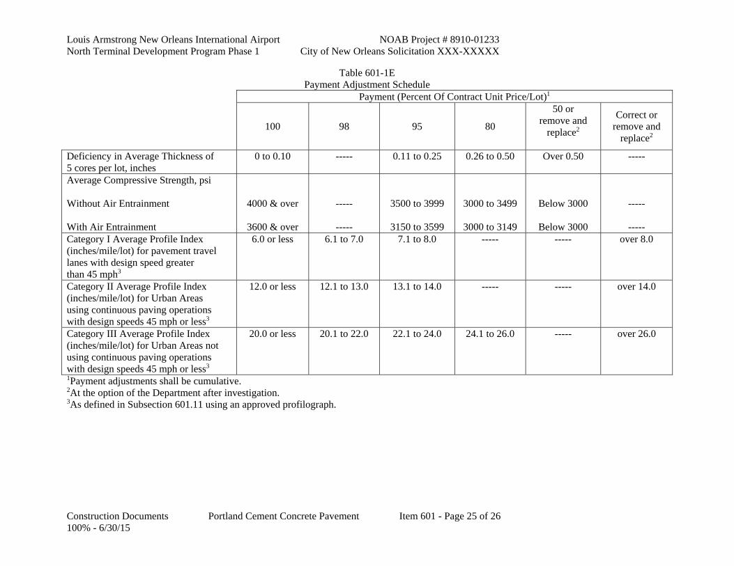
Louis Armstrong New Orleans International Airport NOAB Project # 8910-01233 North Terminal Development Program Phase 1 City of New Orleans Solicitation XXX-XXXXX
Construction Documents Portland Cement Concrete Pavement Item 601 - Page 25 of 26 100% - 6/30/15
Table 601-1E Payment Adjustment Schedule
Payment (Percent Of Contract Unit Price/Lot)1
100 98 95 80
50 or remove and
replace2
Correct or remove and
replace2
Deficiency in Average Thickness of 5 cores per lot, inches
0 to 0.10 ----- 0.11 to 0.25 0.26 to 0.50 Over 0.50 -----
Average Compressive Strength, psi Without Air Entrainment With Air Entrainment
4000 & over
3600 & over
-----
-----
3500 to 3999
3150 to 3599
3000 to 3499
3000 to 3149
Below 3000
Below 3000
-----
----- Category I Average Profile Index (inches/mile/lot) for pavement travel lanes with design speed greater than 45 mph3
6.0 or less 6.1 to 7.0 7.1 to 8.0 ----- ----- over 8.0
Category II Average Profile Index (inches/mile/lot) for Urban Areas using continuous paving operations with design speeds 45 mph or less3
12.0 or less 12.1 to 13.0 13.1 to 14.0 ----- ----- over 14.0
Category III Average Profile Index (inches/mile/lot) for Urban Areas not using continuous paving operations with design speeds 45 mph or less3
20.0 or less 20.1 to 22.0 22.1 to 24.0 24.1 to 26.0 ----- over 26.0
1Payment adjustments shall be cumulative. 2At the option of the Department after investigation. 3As defined in Subsection 601.11 using an approved profilograph.
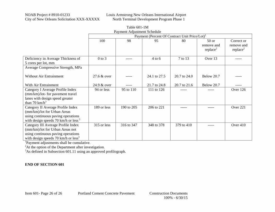
NOAB Project # 8910-01233 Louis Armstrong New Orleans International Airport City of New Orleans Solicitation XXX-XXXXX North Terminal Development Program Phase 1
Item 601- Page 26 of 26 Portland Cement Concrete Pavement Construction Documents 100% - 6/30/15
Table 601-1M Payment Adjustment Schedule
Payment (Percent Of Contract Unit Price/Lot)1 100 98 95 80 50 or
remove and replace2
Correct or remove and
replace2
Deficiency in Average Thickness of 5 cores per lot, mm
0 to 3 ----- 4 to 6 7 to 13 Over 13 -----
Average Compressive Strength, MPa Without Air Entrainment With Air Entrainment
27.6 & over
24.9 & over
-----
-----
24.1 to 27.5
21.7 to 24.8
20.7 to 24.0
20.7 to 21.6
Below 20.7
Below 20.7
-----
----- Category I Average Profile Index (mm/km)/lot- for pavement travel lanes with design speed greater than 70 km/h3
94 or less 95 to 110 111 to 126 ----- ----- Over 126
Category II Average Profile Index (mm/km)/lot for Urban Areas using continuous paving operations with design speeds 70 km/h or less 3
189 or less 190 to 205 206 to 221 ----- ----- Over 221
Category III Average Profile Index (mm/km)/lot for Urban Areas not using continuous paving operations with design speeds 70 km/h or less3
315 or less 316 to 347 348 to 378 379 to 410 ----- Over 410
1Payment adjustments shall be cumulative. 2At the option of the Department after investigation. 3As defined in Subsection 601.11 using an approved profilograph.
END OF SECTION 601

Louis Armstrong New Orleans International Airport NOAB Project # 8910-01233 North Terminal Development Program Phase 1 City of New Orleans Solicitation XXX-XXXXX
Construction Documents Guard Rail Item 704 - Page 1 of 2 100% - 6/30/15
SECTION 704 GUARD RAIL
1.1 DESCRIPTION
A. This work consists of furnishing and constructing beam type highway guard rail in accordance with these specifications, plan details, the manufacturer's recommended procedures and other requirements as directed by the engineerOAR.
1.2 MATERIALS
A. Materials shall comply with the following Section and Subsections.
Cast-in-Place Concrete (Class M) 901
Reinforcing Steel 1009
Metal Beam Guard Rail 1010.08
Posts and Spacer Blocks 1010.09
Hardware 1010.10
Wire Rope and Fittings 1010.11
B. Welding shall comply with Section 815.
1.3 GENERAL CONSTRUCTION REQUIREMENTS
A. Posts: Posts shall be aligned and set plumb. When driving of posts is permitted, the manner of driving shall not damage posts. Post holes shall be backfilled with acceptable material placed and compacted as directed. When posts are to be placed within existing surfaced areas, surface material shall be replaced in kind or with Class M concrete.
B. Rail Elements: Rail elements shall be erected in a manner resulting in a smooth, continuous installation. All bolts, except adjustment bolts, shall be drawn tight. Bolts shall be of sufficient length to extend beyond nuts. Holes for special details may be field drilled or punched when approved. Damaged galvanized surfaces and drilled holes shall be repaired in accordance with Subsection 811.12.
C. Anchor Blocks: Reinforced concrete blocks for anchoring guard rail to existing bridge ends shall meet the requirements of Sections 805 and 806. Concrete shall be Class M complying with Section 901. Required removal of portions of existing bridge railings and drilling of holes into existing railings shall be performed in such manner that will not damage the railings that are to remain. The contractor shall satisfactorily repair damage to the existing bridge due to operations at no additional cost to the DepartmentOwner. Removed materials shall be disposed of in accordance with Subsection 202.02.
D. Guard Rail End Treatments: All guard rail end treatments must have been successfully crash tested and shall comply with the crash test requirements of the National Cooperative Highway Research Program (NCHRP) Report 350. End treatment systems not in compliance with this requirement will not be allowed on any federal or state funded projects.
1. The Bridge Design EngineerOAR has pre-approved a list of end treatment systems for selection by the contractor. The contractor shall provide the project engineerOAR with a copy of the most recent working drawing/shop drawing of the selected guard rail end treatment system prior to installation. The drawings shall provide the details of all

NOAB Project # 8910-01233 Louis Armstrong New Orleans International Airport City of New Orleans Solicitation XXX-XXXXX North Terminal Development Program Phase 1
Item 704- Page 2 of 2 Guard Rail Construction Documents 100% - 6/30/15
components of the guard rail end treatment system and shall state that all details are in compliance with the NCHRP Report 350 requirements as approved by the FHWA.
2. The contractor may select any end treatment, which meets the above criteria, but shall not use a combination of such end treatments on the same project. The contractor shall submit to the Bridge Design Section the system name, the manufacturer of the end treatment system, and the necessary documentation to substantiate that the end treatment is in compliance with the NCHRP 350 requirement.
3. The contractor shall install all components of the guard rail end treatment system such as posts, blocks, and hardware in accordance with the drawings and the manufacturer's recommendations. Under no circumstances shall any component of the guard rail end treatment system be modified without written approval.
4. All end treatments shall be furnished with a retroreflective sheeting at the terminal end as shown in the plans.
5. When necessary, the guard rail length may be adjusted to provide the same "length of need" as specified in the plans. This adjustment shall be made at no additional cost to the DepartmentOwner.
1.4 MEASUREMENT
A. Quantities of guard rail, anchor sections, end treatments, and transitions for payment will be the design quantities as specified on the plans and adjustments thereto. Design quantities will be adjusted if the engineer OAR makes changes to adjust to field conditions, if plan errors are proven, or if design changes are made.
B. Design quantities of single faced guard rail are based on plan length along the face of rail between end posts, exclusive of openings, and plan length of end sections. Design quantities of double faced guard rail are based on plan length between end posts along centerline of posts, exclusive of openings, and plan length of end sections. Design quantities of trailing end and breakaway cable terminal (BCT) anchor sections are based on plan length along the face of rail. Guard rail anchor blocks and end treatments will be measured per each unit furnished and installed.
1.5 PAYMENT
A. Payment for guard rail, anchor sections, anchor blocks, end treatments, and transitions will be made at the contract unit prices which include drilling of holes in existing concrete for reinforcing steel dowels, concrete and reinforcing steel. Payment adjustments for portland cement concrete of Section 901 will not apply.
B. Payment will be made under:
Unit Price Pay items are listed in Section 01 22 00, Unit Price Pay Items. For Work not otherwise identified as being paid on Lump Sum basis, where no pay item is listed in Section 01 22 00, such work is considered subsidiary to other work, or incidental and will not be measured separately for payment.
END OF SECTION 704

Louis Armstrong New Orleans International Airport NOAB Project # 8910-01233 North Terminal Development Program Phase 1 City of New Orleans Solicitation XXX-XXXXX
Construction Documents Concrete Walks, Drives and Incidental Paving Item 706 - Page 1 of 4 100% - 6/30/15
SECTION 706 CONCRETE WALKS, DRIVES AND INCIDENTAL PAVING
1.1 DESCRIPTION
A. This work consists of furnishing and constructing portland cement concrete walks, handicapped curb ramps, drives and incidental paving slabs in accordance with these specifications and in conformity with lines, grades and dimensions shown on the plans or established.
1.2 MATERIALS
A. Materials shall comply with the following Section or Subsections.
Portland Cement Concrete (Class M) 901
Joint Filler 1005.01(c)
Reinforcing Steel 1009.01
Curing Materials 1011.01
1.3 CONSTRUCTION REQUIREMENTS
A. Excavation: Excavation shall be made to required depth and width. The top of the subgrade shall be shaped and compacted to a firm, even surface conforming to the section shown on the plans. Unsuitable material shall be removed and disposed of in accordance with Subsection 202.02 and replaced with approved material at no direct pay.
B. Forms: Forms shall be of wood or metal and shall extend the full depth of concrete. Forms shall be straight, clean and of sufficient strength to resist the pressure of concrete. Bracing of forms shall be such that forms remain in horizontal and vertical alignment until their removal.
1. Concrete may be placed by slip-form methods. Slip-formed concrete shall be placed with an approved machine designed to spread, vibrate, consolidate and finish concrete in one pass of the machine in such manner that minimum hand finishing is necessary. Sliding forms shall be rigidly held together to prevent spreading of forms. After the passing of the side forms there shall be no noticeable slumping of concrete.
C. Subgrade: The subgrade shall be thoroughly moistened immediately prior to placing concrete.
D. Placing and Finishing: Concrete shall be placed on the subgrade, struck off to required thickness and tamped sufficiently to bring the mortar to the surface. The surface shall be finished with a wood float or steel trowel followed by brushing to a slightly rough finish. Joints and edges shall be rounded with an edging tool having a 1/4-inch (6 mm) radius.
E. Joints:
1. Expansion Joints: Expansion joints shall be filled with ½ inch (13 mm) thick preformed expansion joint filler. Expansion joints shall be installed at maximum 100-foot (30 m) intervals, and between intersecting paving and any fixed structure such as a building, bridge or curbing. Expansion joint material shall extend for the full width and depth of paving.
2. Weakened Plane: Weakened planes shall be formed by a jointing tool or other acceptable means. Weakened planes shall extend into concrete for at least 1/4 of the depth and shall be approximately 1/8 inch (3 mm) wide.
a. Walks: Spacing of weakened planes for walks shall be equal to the width of walk.

NOAB Project # 8910-01233 Louis Armstrong New Orleans International Airport City of New Orleans Solicitation XXX-XXXXX North Terminal Development Program Phase 1
Item 706- Page 2 of 4 Concrete Walks, Drives and Incidental Paving Construction Documents 100% - 6/30/15
b. Drives: A longitudinal weakened plane shall be formed along the centerline of drives more than 16 feet (5 m) wide, and transverse weakened planes shall be formed at not more than 16-foot (5 m) intervals.
c. Incidental Paving: Weakened planes for incidental paving shall be formed at intervals not exceeding 30 times the thickness of the concrete in length or width. Incidental paving poured adjacent to jointed concrete shall be jointed to match existing joints, with intermediate joints formed as necessary not to exceed the maximum joint spacing.
3. Construction Joints: Construction joints shall be formed around manholes, utility poles, etc., extending into paving and 1/4 inch (6 mm) thick preformed expansion joint filler shall be installed aroundin these joints. End of paving sequence shall be accomplished with a construction joint.
4. Tie-ins: Tie-ins of existing concrete shall be made by full depth sawing at no direct pay.
F. Curing: Concrete shall be cured in accordance with Subsection 601.10.
G. Detectable Warning Surface for Handicap Ramps: Handicapped curb ramps installed shall be equipped with a detectable surface warning system consisting of raised truncated domes as a transition between the sidewalk and the street as required by the Americans with Disabilities Act, 28 CFR Part 36, ADA Standards for Accessible Design. These standards are further described in the Americans with Disabilities Act Accessibility Guidelines (ADAAG), Section 4.29.2.
1. Detectable warnings (truncated domes) shall be installed on the ramp surface over the full width of the ramp throat for a distance of 24 inches (600 mm) in the direction of travel from the back of the curb. Truncated domes shall be laid out on a square or triangular grid in order to allow enough space for wheelchairs to roll between the domes. Light reflectance of the truncated domes and the underlying surface must meet the 70 percent contrast requirement of ADAAG.
1.4 MEASUREMENT
A. Quantities of concrete walks, drives and incidental paving slabs for payment will be the design quantities as specified on the plans and adjustments thereto. Design quantities will be adjusted if the engineer OAR makes changes to adjust to field conditions, if design errors are proven or if design changes are made. Design areas are based on the horizontal dimensions shown on the plans. Excavation, backfill, reinforcing steel and joint materials will not be measured for payment.
B. Handicapped curb ramps included in the construction of a concrete walk, including the detectable surface warning system, will not be measured for payment.
1.5 PAYMENT
A. Payment for concrete walks, drives and incidental paving will be made on a lot basis at the contract unit price per square yard (sq m), adjusted in accordance with the following provisions. Payment for each lot will be made in accordance with Table 901-6. Size, sampling, and testing of each concrete lot shall be in accordance with the Materials Sampling Manual.
B. Payment will be made under:
Unit Price Pay items are listed in Section 01 22 00, Unit Price Pay Items. For Work not otherwise identified as being paid on Lump Sum basis, where no pay item is listed in Section 01 22 00, such work is considered subsidiary to other work, or incidental and will not be measured separately for payment.

Louis Armstrong New Orleans International Airport NOAB Project # 8910-01233 North Terminal Development Program Phase 1 City of New Orleans Solicitation XXX-XXXXX
Construction Documents Concrete Walks, Drives and Incidental Paving Item 706 - Page 3 of 4 100% - 6/30/15
END OF SECTION 706

NOAB Project # 8910-01233 Louis Armstrong New Orleans International Airport City of New Orleans Solicitation XXX-XXXXX North Terminal Development Program Phase 1
Item 706- Page 4 of 4 Concrete Walks, Drives and Incidental Paving Construction Documents 100% - 6/30/15
THIS PAGE INTENTIONALLY LEFT BLANK

Louis Armstrong New Orleans International Airport NOAB Project # 8910-01233 North Terminal Development Program Phase 1 City of New Orleans Solicitation XXX-XXXXX
Construction Documents Curbs and Gutters Item 707 - Page 1 of 4 100% - 6/30/15
SECTION 707 CURBS AND GUTTERS
1.1 DESCRIPTION
A. This work consists of furnishing and constructing curbs and gutters in accordance with these specifications and in conformity with lines, grades, dimensions and typical sections shown on the plans or established.
1.2 MATERIALS
A. Materials shall comply with the following Sections and Subsections:
Usable Soil 203.06(a)Item P152
Asphaltic Concrete 502Not used
Portland Cement Concrete (Class M) for Dowelled or Integral Barrier Curb at non-airfield areas or Dowelled for airfield areas.
901
Portland Cement Concrete for Integral Barrier Curb at Tug Pavement
Item P-501
Asphalt Cement 1002Not used
Aggregates 1003
Joint Fillers 1005.01
Joint Sealant 1005.02
Joint Seals 1005.03
Curing Materials 1011.01
Form Release Agent 1018.24
B. Concrete Curbs and Gutters: When slip-formed methods are used, concrete shall have not more than a 1 1/2 inch (40 mm) slump.
C. Asphaltic Curbs: Mixtures for these curbs shall be Superpave Asphaltic Concrete (Level A) in accordance with Section 502.Asphalt curbs not used in this project.
1.3 SUBGRADE
A. The subgrade shall be shaped and compacted to a firm, even surface. When possible, the subgrade shall be shaped and compacted at the same time and in the same manner as the subgrade for the pavement. Unsuitable material shall be removed and replaced with approved material at no direct pay.
1.4 CONCRETE FORMS
A. Forms for combination curb and gutter shall conform to Subsections 601.03(c) and 601.05. Forms for other curbs or gutters shall be wood or metal, straight, and of sufficient strength to resist pressure of the concrete without deforming. Forms shall be cleaned and coated with form release agent before concrete is placed against them. Forms which have become excessively worn, bent or broken shall not be used. An approved mechanical curb forming machine conforming to Subsection 707.06(c) may be used without forms.

NOAB Project # 8910-01233 Louis Armstrong New Orleans International Airport City of New Orleans Solicitation XXX-XXXXX North Terminal Development Program Phase 1
Item 707- Page 2 of 4 Curbs and Gutters Construction Documents 100% - 6/30/15
1.5 CONCRETE JOINTS
A. Joints shall be formed in integral curbing to correspond with transverse joints in the pavement slab. Joints shall extend under and through the curb and shall be finished and filled with the specified filler in accordance with the particular concrete specification (Item P501 or LADOTD 610, etc).
B. Other types of curbing shall be provided with 1/4 inch (6 mm) joints at maximum intervals of 20 feet (6 m) formed by using steel plates 1/4 inch (6 mm) thick, cut to section and set vertically in forms until concrete has set sufficiently to permit removal of plates or as indicated in the plans.
1.6 PLACING CONCRETE
A. Integral Types: After concrete pavement has been struck off, curb forms shall be clamped or otherwise securely fastened in place on the slab form. Concrete for curbing shall be placed and thoroughly tamped within 30 minutes after pavement has been finished. Concrete shall be spaded or vibrated sufficiently to eliminate voids and shall be tamped to bring mortar to the surface. The concrete shall be finished smooth and even with a wooden float. Edges shall be rounded with an approved finishing tool to the specified radius. Care shall be taken to secure monolithic construction.
1. Integral type curb may be placed after completion of pavement, provided reinforcing steel is placed in the pavement of the size, type and spacing shown on the plans at no direct pay.
B. Non-Integral Types: Concrete shall be placed on the prepared subgrade, struck off and consolidated to required thickness. Concrete shall be spaded or vibrated sufficiently to eliminate voids and shall be tamped to bring mortar to the surface, after which it shall be finished smooth and even with a wooden float. Edges shall be rounded to the specified radius.
C. Slip-formed Concrete: Slip-formed concrete shall have uniform consistency and shall be placed with an approved extrusion machine designed to spread, consolidate and finish concrete in one pass of the machine such that minimum hand finishing is necessary. Sliding forms shall be rigidly held together to prevent spreading of forms. After the passing of the forms there shall be no noticeable slumping of concrete. Finished concrete shall be free from voids. Any additional finishing required shall be performed immediately after placement.
D. Tolerances: Grade of combination curb and gutter shall not exceed the theoretical grade and shall not be more than 1/2 inch (13 mm) low.
1.7 FINISHING
A. Forms shall be removed within 24 hours after concrete has been placed. Minor Honeycombed honeycombed areas (less than ½ inch in size and not more than 1 per foot section) and other minor defects shall be filled with mortar composed of portland cement and sand complying with Subsection 702.02. Plastering will not be permitted on faces of curb or gutter. Rejected curb or gutter shall be removed and replaced. The top and face of curb or gutter shall be finished prior to initial set with a wood float, brush, and water.
1.8 ASPHALTIC CURB
A. Asphaltic curb shall be placed by an approved extruding machine. Prior to placing curb, the contractor shall apply asphaltic tack coat complying with Section 504.Not used.
1.9 CURING CONCRETE CURB OR GUTTERS
A. After finishing, curb or gutter shall be cured in accordance with Subsection 601.10.

Louis Armstrong New Orleans International Airport NOAB Project # 8910-01233 North Terminal Development Program Phase 1 City of New Orleans Solicitation XXX-XXXXX
Construction Documents Curbs and Gutters Item 707 - Page 3 of 4 100% - 6/30/15
1.10 BACKFILLING
A. After curb or gutter has set sufficiently, the contractor shall backfill adjacent to curb or gutter with usable soil compacted to the density of surrounding soil.
1.11 MEASUREMENT
A. Quantities of curbs and/or gutters for payment will be the design lengths as specified on the plans and adjustments thereto. Design quantities will be adjusted if the engineer OAR makes changes to adjust to field conditions, if design errors are proven, or if design changes are made. Excavation, backfill, joint materials, asphaltic tack coat and steel tie bars will not be measured for payment. When combination curb and gutter is specified, gutters required at catch basins will be included in design quantities for combination curb and gutter.
1.12 PAYMENT
A. Payment for curbs and/or gutters will be made at the contract unit price per linear foot (lin m), subject to the following provisions:
B. Asphaltic Mixtures: Asphaltic curbs will be subject to the payment adjustment provisions for air voids under of Section 502. Asphalt cement shall comply with the requirements of Section 1002. The Materials and Testing Section will provide the payment adjustment percentage for properties of asphalt cement. Not used.
C. Portland Cement Concrete: The concrete in the curbs and/or gutters will be identified by lots and shall be subject to pay adjustments per linear foot (lin m) in accordance with Table 901-6. Size, sampling, and testing of each concrete lot shall be in accordance with the Materials Sampling Manual.
D. Payment will be made under:
Unit Price Pay items are listed in Section 01 22 00, Unit Price Pay Items. For Work not otherwise identified as being paid on Lump Sum basis, where no pay item is listed in Section 01 22 00, such work is considered subsidiary to other work, or incidental and will not be measured separately for payment.
END OF SECTION 707

NOAB Project # 8910-01233 Louis Armstrong New Orleans International Airport City of New Orleans Solicitation XXX-XXXXX North Terminal Development Program Phase 1
Item 707- Page 4 of 4 Curbs and Gutters Construction Documents 100% - 6/30/15
THIS PAGE INTENTIONALLY LEFT BLANK

Louis Armstrong New Orleans International Airport NOAB Project # 8910-01233 North Terminal Development Program Phase 1 City of New Orleans Solicitation XXX-XXXXX
Construction Documents Riprap Item 711 - Page 1 of 4 100% - 6/30/15
SECTION 711 RIPRAP
1.1 DESCRIPTION
This work consists of furnishing and placing riprap in accordance with these specifications and in conformity to lines, grades and thickness shown on the plans or as directed.
1.2 MATERIALS
Stone riprap shall be from an approved source listed in QPL 2. Stone riprap shall not disintegrate upon exposure to the elements or be easily broken from handling, and shall be reasonably free from earth and other foreign materials. When tested in accordance with AASHTO T 85, the solid weight of stone shall be at least 155 pounds per cubic foot (2490 kg/cu m) (based on bulk specific gravity). The least dimension of any individual stone shall be at least 1/3 its maximum dimension. Each shipment of stone shall be reasonably well graded within the specified limits.
Recycled concrete may be used as riprap unless otherwise indicated in Heading (a), provided its solid weight is at least 155 pounds per cubic foot (2490 kg/cu m) (based on bulk specific gravity) and it is free of protruding reinforcement.
Stockpiles of recycled concrete shall be source approved prior to use and kept separate from other materials. Stockpiles shall be uniform and free of soil, debris, excessive amounts of asphaltic materials, and foreign matter. Once a stockpile has been approved as an acceptable source of material, no material shall be added without prior approval.
Control of gradation will be by visual inspection at the source, project site or both.
Any difference of opinion between the engineer OAR and contractor will be resolved by checking the gradation of two random truckloads (or equivalent size samples). Equipment, labor and sorting site shall be furnished by the contractor at no direct pay.
a. Riprap: Riprap shall be reasonably well graded and shall comply with Table 711-1.
Table 711-1 Riprap
Riprap Class 1 Stone Size
lb (kg) Spherical Diameter,
ft (mm) 2 Percent of Stone
Smaller Than 2 lb (1 kg) 10 (4.5)
4 (2) 2 (1)
0.75 (0.30)
0.51 (155) 0.38 (115) 0.30 (90) 0.22 (65)
100 40-100 15-50 0-15
10 lb (5 kg) 50 (23) 20 (9) 10 (5) 5 (2.5)
0.88 (270) 0.65 (200) 0.51 (155) 0.41 (125)
100 50-100 15-50 0-15
30 lb (15 kg) 140 (64) 60 (27) 30 (15) 10 (4.5)
1.24 (375) 0.94 (285) 0.74 (225) 0.51 (155)
100 42-100 15-50 0-15
55 lb (25 kg) 3 275 (125) 110 (50) 55 (25) 20 (9)
1.50 (460) 1.11 (335) 0.88 (270) 0.63 (190)
100 42-100 15-50 0-15

NOAB Project # 8910-01233 Louis Armstrong New Orleans International Airport City of New Orleans Solicitation XXX-XXXXX North Terminal Development Program Phase 1
Item 711- Page 2 of 4 Riprap Construction Documents 100% - 6/30/15
130 lb (60 kg) 3 650 (295) 260 (120) 130 (60) 40 (18)
2.00 (610) 1.46 (450) 1.17 (360) 0.79 (240)
100 45-100 15-50 0-15
250 lb (115 kg) 3 1250 (570) 500 (225) 250 (115) 80 (35)
2.50 (760) 1.83 (560) 1.46 (445) 1.00 (300)
100 45-100 15-50 0-15
440 lb (200 kg) 3 2200 (1000) 900 (410) 440 (200) 130 (60)
3.00 (915) 2.23 (680) 1.76 (535) 1.17 (360)
100 40-100 14-50 0-15
1000 lb (455 kg) 3 5000 (2270) 2000 (910) 1000 (455) 300 (135)
4.00 (1205) 2.91 (885) 2.31 (705) 1.55 (470)
100 45-100 10-50 0-15
1The stone size used to define the Riprap Class is the minimum median stone size for the stone class. The minimum thickness of a riprap layer shall be no less than the spherical diameter of the maximum stone size in the Riprap Class. 2Spherical diameters of riprap classes up to 30 lb (15 kg) are based on a solid weight of 140 lb/cu ft (2240 kg/cu m). Spherical diameters of riprap classes above 30 lb (15 kg) are based on a solid weight of 155 lb/cu ft (2480 kg/cu m). 3Recycled portland cement concrete may not be used in these riprap classes. b. Geotextile Fabric: Geotextile Fabric shall comply with Section 1019.01.
1.3 CONSTRUCTION REQUIREMENTS
Riprap: Areas on which riprap is to be placed shall be graded to the required section. Riprap shall be placed on the prepared slope or area in a manner which will produce a reasonably well-graded mass of stone with a minimum practicable percentage of voids. The entire mass of stone will be placed to be in conformance with the lines, grades, and thickness at one operation and to avoid displacing underlying material. Placing of riprap in layers, or dumping into chutes, or by similar methods likely to cause segregation, will not be permitted.
When placement in water currents is required, the contractor shall make drift checks and place riprap in such manner as to compensate for drift. The contractor shall furnish necessary facilities and personnel for checking riprap depth and distribution.
Filter Stone: When specified, filter stone shall be placed on the prepared slope or area before placement of riprap. When filter stone is placed under water, free dumping will not be permitted. Underwater placement shall be by controlled methods using bottom dump buckets or wire rope baskets lowered through the water to the point of placement. If placement in strong water currents is required, placement of riprap will follow soon after placement of filter stone. Unless shown otherwise on the plans or directed, filter stone shall be Riprap Class 10 lb (5 kg) or less.
Geotextile Fabric: When specified, geotextile fabric shall be placed on the prepared slope or area in accordance with Subsection 203.11(c) before placement of riprap. Care shall be taken not to damage the geotextile fabric when placing riprap. Placing riprap by rolling riprap down slope, or dropping riprap from extreme heights, or by similar methods likely to damage geotextile fabric, will not be permitted. Damaged geotextile fabric shall be repaired in accordance with Subsection 203.11(c) or replaced as directed.

Louis Armstrong New Orleans International Airport NOAB Project # 8910-01233 North Terminal Development Program Phase 1 City of New Orleans Solicitation XXX-XXXXX
Construction Documents Riprap Item 711 - Page 3 of 4 100% - 6/30/15
1.4 MEASUREMENT
Riprap and filter stone may be measured on either a square yard (sq m), cubic yard (cu m), or weight (mass) basis as specified.
When measured on a square yard (sq m) basis, the quantity measured will be that actually placed to the limiting dimensions shown on the plans or as directed by the engineerOAR.
When measured on a cubic yard (cu m) basis, measurement will be made in vehicles at the point of delivery on the project in accordance with Subsection 109.01.
When measured on a weight (mass) basis the pay unit will be per ton (2000 pounds) [Mg (1000 kg)].
When riprap is delivered by vehicles or railroad cars, measurement will be based on certified weight (mass) tickets furnished by the contractor.
When riprap is delivered by barge, measurement will be made by calculation from barge displacement, based on water weighing 62.4 pounds per cubic foot (1000 kg/cu m).
Geotextile fabric will be measured by the square yard (sq m) of covered area in place.
No measurement will be made for excavation or backfilling.
1.5 PAYMENT
Payment for riprap and geotextile fabric will be made at the contract unit prices. Filter stone will be paid for as riprap.
Payment will be made under:
Unit Price Pay items are listed in Section 01 22 00, Unit Price Pay Items. For Work not otherwise identified as being paid on Lump Sum basis, where no pay item is listed in Section 01 22 00, such work is considered subsidiary to other work, or incidental and will not be measured separately for payment.
END OF SECTION 711

NOAB Project # 8910-01233 Louis Armstrong New Orleans International Airport City of New Orleans Solicitation XXX-XXXXX North Terminal Development Program Phase 1
Item 711- Page 4 of 4 Riprap Construction Documents 100% - 6/30/15
THIS PAGE INTENTIONALLY LEFT BLANK

Louis Armstrong New Orleans International Airport NOAB Project # 8910-01233
North Terminal Development Program Phase 1 City of New Orleans Solicitation XXX-XXXXX
100% Construction Documents Traffic Signs and Devices Item 729 - Page 1 of 18
Revision 1 - 7/6/15
SECTION 729 TRAFFIC SIGNS AND DEVICES
1.1 RELATED DOCUMENTS
A. Drawings and general provisions of the Contract, including Division 01 Specification Sections,
apply to this section.
B. Manual on Uniform Traffic Control Devices (MUTCD)
C. Louisiana Standard Specifications for Roads and Bridges 2006 Edition (LSSRB)
D. Louisiana Work Zone Traffic Control Details
E. LADOTD Temporary Traffic Control Standard Details (TTC-00 to TTC-19)
F. “Quality Guidelines for Work Zone Traffic Control Devices” standard by American Traffic
Safety Services Association (ATSSA)
G. US DOT/FHWA 2012 Supplement to the 2004 Edition (English Version) Standard Highway
Signs Including Pavement Markings and Standard Alphabets (“Standard Highway Signs”)
H. LADOTD Roadside Traffic Signs details (1-11)
I. LADOTD Overhead Traffic Signs details (1-16)
1.2 DESCRIPTION
A. This work consists of furnishing and installing traffic signs, dead end road installations,
markers and delineators, with accessories, posts and overhead spans of specified materials,
sizes, shapes, weights and designs.
B. In general, the work and materials shall comply with the MUTCD as modified by these
specifications or as shown on the plans.
C. Signs shall be fabricated in an approved plant. The term "legend" shall mean border strip,
letters, numerals and symbols which convey the message on signs.
1.3 MATERIALS
A. Materials shall be new stock conforming to the following:
1. Sign and Marker Sheeting: Sheeting material for sign panels, delineators, barricades and
other markers shall comply with LSSRB Section 1015. Except for the overhead and
ground-mounted wayfinding guides signs for the North Terminal, all permanent signs shall
meet the requirements of ASTM D 4956, Type X All wayfinding guide signs for the North
Terminal shall meet the requirements of ASTM D 4956, Type XI.
2. Ferrous Metal: Ferrous metals shall comply with LSSRB Subsection 1015.02(a).
Reinforcing steel shall comply with Section 1009. Ferrous metal, except reinforcing steel,
shall be galvanized in accordance with LSSRB Section 811.
3. Aluminum: Aluminum alloys for structural members shall comply with Subsection
1015.02(b). Aluminum sign panels shall comply with LSSRB Subsection 1015.04(a).
4. Fittings: Structural bolts, nuts, washers and miscellaneous hardware shall comply with
LSSRB Subsection 1015.02.
5. Guard Rail: Guard rail materials for dead end road installations shall comply with LSSRB
Section 1010.

NOAB Project # 8910-01233 Louis Armstrong New Orleans International Airport
City of New Orleans Solicitation XXX-XXXXX North Terminal Development Program Phase 1
Item 729- Page 2 of 18 Traffic Signs and Devices 100% Construction Documents
Revision 1 - 7/6/15
6. Timber: Treated piling and timber for barricades in dead end road installations shall
comply with LSSRB Section 1014.
7. Concrete: Concrete shall be Class M complying with LSSRB Section 901.
8. Flexible Sign Posts: Flexible posts for small signs, markers and delineators shall comply
with LSSRB Subsection 1015.03.
9. Silk Screen Paste: Silk screen paste shall be as recommended by the sheeting manufacturer.
10. U-Channel Posts: U-channel posts shall comply with LSSRB Subsection1015.02(a)(3).
1.4 GENERAL REQUIREMENTS
A. Sign Face Fabrication: Signs of Types A, B, D and E, overhead signs and sign face overlay
panels shall be fabricated in accordance with the MUTCD, the "Standard Highway Signs"
booklet, and the signing detail sheets of the plans.
1. The contractor shall furnish shop drawings of sign faces for Types D and E, overhead signs
and sign overlay panels and for any non-standard sign faces of Types A andB. Approval of
shop drawings shall be obtained before sign face fabrication is begun.
2. The fabricator of the bolted extruded aluminum panel signs shall coordinate with the
structural engineer and structural fabricator who are designing the structural supports and
attachment assemblies for the ground-mounted and overhead signs to confirm sign di
mensions and locations on the supports and ensure compatibility of the sign panel with the
proposed attachment method.
3. The fabricator of the digitally printed custom sign faces must have successfully fabricated
digitally printed custom sign faces on ASTM Type XI sheeting for at least two prior guide
sign or wayfinding signing projects in the United States during the past 5 years for a large
commercial passenger airport, large amusement/theme park, or a state department of
transportation. Such projects must have included both roadside mounted and overhead
guide/wayfinding signs and must have included a total of at least 12 signs. In addition, at
least one of these projects must have require application of digitally printed sheeting to
extruded aluminum panel sign faces. Such signs must have been already installed on site
and accepted by the owners of their respective projects. Submit to the OAR a summary of
the fabricator’s qualifications, including a list of references with contact names and
telephone numbers of owners of prior projects within the past three years that can confirm
the fabricator’s prior work and quality thereof. The fabricator’s qualifying experience must
have been attained prior to the prime contractor’s submission of bid for this project. Do not
submit other construction contractors as references; references must be from the owner of
the sign panels or the owner’s authorized representative.
B. Sign Mountings Fabrication: The contractor shall furnish steel sign supports for both post
mountings and overhead mountings and either rigid steel or flexible posts for small signs,
markers and delineators. Before beginning work, the contractor shall notify the OAR in writing
of signing materials he proposes to furnish. The same signing materials shall be used
throughout the project.
1. Fabrication of sign mountings shall conform to LSSRB Section 807. The contractor shall
furnish fabrication and erection drawings, signed and sealed by a Louisiana-licensed
Professional Engineer, of all sign mountings in accordance with LSSRB Subsection 801.03
with the exception of standard roadside installations. Fabrication and erection drawings will
be approved only after approval of sign face shop drawings. Neither fabrication of sign

Louis Armstrong New Orleans International Airport NOAB Project # 8910-01233
North Terminal Development Program Phase 1 City of New Orleans Solicitation XXX-XXXXX
100% Construction Documents Traffic Signs and Devices Item 729 - Page 3 of 18
Revision 1 - 7/6/15
mountings nor construction of sign footings will be allowed before drawings are approved
and distributed.
2. Dimensions shown in the plans are approximate. The contractor shall survey the as-built
ground lines at each proposed ground-mounted Type D sign and each proposed overhead
sign location prior to fabricating the supports to confirm the lengths, span widths and sizes
of support required.
3. Structure mounted delineator and milepost assemblies shall be installed in accordance with
plan details.
4. Welding shall comply with LSSRB Section 815.
5. Roadside Type D & E Signs - Any support sizes and lengths shown on or implied by the
plans are approximate. Determine the exact size and length of supports based upon as-built
ground lines before fabrication.
a. Structural Steel Beam Sign Supports – For roadside-mounted bolted extruded
aluminum panel guide signs being installed on Airport Road, design and fabricate
structural steel beam sign supports in accordance with LA DOTD Bridge and Structural
Design Standard Drawing Nos. BD.2.7.2.0.1 and BD.2.7.2.0.8. The Contractor shall
perform necessary surveys to determine ground line elevations and sign support lengths
and shall perform all necessary geotechnical investigations to design the foundations
for the steel beam sign supports. Provide breakaway bases for the steel beam supports
in accordance with LA DOTD Bridge and Structural Design Standard Drawing Nos.
BD.2.7.2.0.10 and BD.2.7.2.0.11. Construct the foundations, erect the beam supports
on the foundations and mount the extruded panel sign on the beam supports.
b. Hollow Structural Steel (HSS) (i.e., Structural Tube Supports) – For roadside
wayfinding guide signs installed at the North Terminal, provided rectangular hollow
structural steel (HSS) sign supports with omni-directional breakaway bases.
1) Design and fabricate ground-mounted structural tube supports from seamless steel
or extruded aluminum tubes with a square cross-section. The ground-mounted
structural tube supports shall have nominal outer dimensions of no less than 4” x 4”
and no greater than 5” x 5”.
2) The depth of the support shall be sufficient to accommodate the mounting of the
bolted extruded aluminum panel sign(s) of the required thickness to the inside face
of the support with the face of the sign panel aligned with the front face of the
support (i.e., the supports will “frame” the sides of the bolted extruded aluminum
panel signs). In addition, the depth of the sign support shall accommodate a
structural angle attached vertically along back side of the sign panel and the inside
face of the support to mount the sign to the support. The flange of the angle shall
not extend beyond the rear face of the support. The top of each support shall be
flush with the top of the bolted extruded aluminum panel sign attached. Weld the
structural angle to the structural tube at the proper height and recess on the support
prior to galvanizing and finish coating the sign support. Coordinate with the
fabricator of the bolted extruded aluminum panel signs to confirm sign dimensions.
3) Survey the as-built ground lines of at each of the proposed ground-mounted guide
and information sign location prior to fabricating the supports to confirm the
lengths of and size of support required.

NOAB Project # 8910-01233 Louis Armstrong New Orleans International Airport
City of New Orleans Solicitation XXX-XXXXX North Terminal Development Program Phase 1
Item 729- Page 4 of 18 Traffic Signs and Devices 100% Construction Documents
Revision 1 - 7/6/15
4) Furnish and install Break-Safe® Model AS or B650 omni-directional breakaway
bases and hinges by Transpo Industries, Inc., or an Owner-approved equal for each
sign support based on the size of square tube support. Provide all necessary anchor
assemblies, sign post brackets, bracket hardware assemblies, couplings and special
bolt assemblies, hinge assemblies, and hinge hardware assemblies to form a
complete breakaway sign post system.
6. Post-Mounted Signs for Parking Lots
a. Solid/Non-Perforated Square Tube Sign Posts. Furnish solid, non-perforated square
tube sign posts for flat sheets signs being installed on within parking lots as shown in
the plans. Provide 2-inch square 12 gauge steel tubes that are hot-dipped galvanized
according to ASTM A653 and conform to ASTM A1011, Hot-Rolled Carbon Sheet
Steel, with a minimum yield strength of 33,000 psi. Furnish tubes with corners welded
together using high-frequency resistance welding. The post shall be externally scarfed
to agree with standard corner radii of 5/32”, ± 1/64”. Provide a square anchor sleeve
and associated concrete footing for each solid/non-perforated square tube sign post that
comply with the details shown in the plans.
b. Furnish cast aluminum finials for each solid/non-perforated square tube sign post.
Provide finials with a low profile pyramidal shape designed to fit over the top of a
square tube post of the size and to be secured to the outside wall of the post using set
screws. Provide each finial with all hex set screws necessary to securely fasten the
finial to the top of the sign post.
c. Tri-Frame Sign Posts - Design and fabricate the sign supports with 3-sided frame at top
of post for wayfinding signs to be installed in parking lots in accordance with the
structural details provided in the Plans. Submit shop drawings for review and approval
prior to fabrication. Powder-coat the sign supports with a black (or other color
designated by the Owner) powder coated finish. Submit manufacturer’s color charts to
the OAR to confirm the Owner’s choice of color for the powder coating at least 30
days prior to applying the coating to the sign posts. Do not apply powder coating until
coating color and luster is confirmed and approved by the OAR. Prepare the
galvanized surface of the post to receive the powder coating following the
recommendations of the American Galvanizers Association (www.galvanizeit.org) as
well as the coating manufacturer’s instructions. Comply with ASTM D 6386.
Remove all surface contaminants by washing with a manufacturer recommended
detergent or degreaser, then apply a wash primer (i.e., etch primer). Apply the coating
to all exterior surfaces of the sign post indoors in a controlled environment in
accordance with the manufacturer’s instructions. Only touch-up paint may be field-
applied, as necessary and as approved by the OAR, following installation.
7. Overhead Sign Supports. Overhead sign supports consist of both cantilevered and full-span
(i.e., gantry) sign structures. The Base Bid for this contract is comprised of standard LA
DOTD ground-mounted overhead sign trusses and ground-mounted cantilevers. Monotube
overhead sign structures are proposed as Additive Alternate No. CI-05 in lieu of LA DOTD
standard structures.
a. General
Louis Armstrong New Orleans International Airport NOAB Project # 8910-01233
North Terminal Development Program Phase 1 City of New Orleans Solicitation XXX-XXXXX
100% Construction Documents Traffic Signs and Devices Item 729 - Page 5 of 18
Revision 1 - 7/6/15
i. The proposed span lengths, foundation locations, and elevations differences
shown on the signing plans and overhead sign elevation drawings are provided to
convey the Owner’s intent and to provide information for bidding. Field-verify
span lengths, foundation locations and elevations prior to designing and
fabricating the signs. Stake the locations of the proposed foundations for the
OAR’s review and approval prior to fabricating the structures and constructing
the foundations. Prepare and submit finalized sign elevation drawings for review
and approval. Take care to ensure that structures are designed based upon the
final ground line and elevations, including the construction of any proposed
landscaping berms.
ii. Do not provide cover bases or individual anchor bolt covers on support anchor
bases regardless of support location.
iii. Design overhead sign supports to accommodate the future addition of new sign
panels or future replacement of initial sign panels where such future signs and
their sizes are shown in the plans.
iv. Furnish overhead sign structures with a standard galvanized finish. As an
Additive Alternate, provide overhead sign structures with a coated finish in
accordance with the Sign Support Finish subsection below.
b. Monotube Overhead Sign Supports (Additive Alternate No. CI-05)
i. Design and fabricate monotube overhead sign structures from seamless steel pipe
that has a constant circular cross section and constant outer diameter of that is not
less than 18” nor greater than 24”. The contractor may provide overhead
monotube sign structures of a common outer diameter or of two outer diameters.
If two outer diameters are used, use the larger outer diameter for the longer span
sign Spans and the smaller outer diameter for the shorter span sign Spans.
However, tubing segments comprising a given structure must have the same
outer diameter. Tapers and variations in tube diameter and cross section along a
structure are not permitted. The mast arm pipe diameter shall be the same as the
column pipe diameter. Tubing shall be seamless and uniform in quality and
temper. Exterior and interior surfaces shall be clean, smooth and free of seams,
slivers, laminations, grooves, cracks or other defects. Fluted, multi-sided or
textured surfaces are not permitted. All structures provided shall have a uniform
appearance.
ii. Each vertical member or column of the monotube sign structure shall be
fabricated from a single, continuous pipe segment with a 90-degree bend formed
at the top end by heat treatment or by methods which will not crimp or buckle the
interior radius of the pipe bend. Maintain a consistent cross-section and outer
diameter through the bend. The centerline radius of bend between the horizontal
(mast arm) and vertical (column) portions of the support shall be 8 feet, unless
otherwise approved by the Owner. If a bend radius different from 8 feet is
proposed and approved, it shall be used for all monotube overhead sign structures
provided on the project. Confirm that sign structure will accommodate the
proper lateral positioning of the overhead signs relative to the roadway below as
shown in the overhead sign elevation drawings provided in the plans, examining

NOAB Project # 8910-01233 Louis Armstrong New Orleans International Airport
City of New Orleans Solicitation XXX-XXXXX North Terminal Development Program Phase 1
Item 729- Page 6 of 18 Traffic Signs and Devices 100% Construction Documents
Revision 1 - 7/6/15
specifically the any overlap of signs and the field splice/bolted connection
between column and the mast arm.
iii. Fabricate each overhead monotube sign structure into the largest practical
sections prior to galvanizing. All monotube sign structures shall have a bolted
field splice at each end of the horizontal mast arm where it meets the curved top
of the column. For mast arm lengths between 40 feet and 80 feet an additional
bolted field splice will be permitted at the midpoint of the mast arm to facilitate
galvanizing, finish-coating and hauling operations. For mast arms with lengths
greater than 80 feet, two additional bolted field splices will be permitted at the
1/3 points to facilitate galvanizing, finish coating and hauling operations. Submit
splice locations to the OAR for approval and do not commence fabrication until
splice locations are approved.
iv. The monotube sign structure typical drawings in the plans are provided to
illustrate the Owner’s intent along with basic design requirements. They serve as
guidelines and do not constitute design drawings.
v. Subject to the approval of the OAR, the Contractor may modify the span lengths
shown in plans to facilitate more efficient fabrication of the monotube structures,
provided that doing so will not create the need for guardrail to protect a sign
column or foundation where none has been proposed or require major adjustment
or relocation of underground utilities. The Contractor shall be responsible for
and bear the cost of utility adjustments and relocations necessitated by the
Contractor’s adjustment in span lengths and corresponding change in foundation
locations. The installation of guardrail protection in order to relocate foundations
and shorten span lengths will not be allowed.
vi. Galvanize all monotube members inside and out after fabrication. All nuts, bolts
and washers used for the sign structure shall be galvanized after fabrication.
vii. As Additive Alternate No. CI-07, apply a finish coat to the monotube structures
according to the Sign Support Finish subsection below. Prepare the galvanized
finish on the outside of the monotube members for powder coating or painting
using a method agreed upon by the coating manufacturer and the galvanizer.
8. Sign Support Finish (Additive Alternate Nos.CI-06, CI-07 and CI-08)
a. As Additive Alternate Nos. CI-06 (for LADOTD sign trusses and cantilevers) and CI-
07 (for overhead monotube sign supports), apply a solid white (or other color specified
by the Owner) finish coating to the outer surface of all overhead sign structures by
powder coating or wet painting. Coat the supports with a highly durable, long-lasting,
colorfast painted or powder coated finish.
b. As Additive Alternate CI-08, apply a solid white (or other color specified by the
Owner) finish coating to the outer surface of all hollow structural steel (HSS) (i.e.,
structural tube ground-mounted sign supports) by powder coating or wet painting. Paint
or powder-coat the hinge assemblies and hinge hardware to match the color and luster
of the painted or powder-coated finish applied to the HSS sign supports.

Louis Armstrong New Orleans International Airport NOAB Project # 8910-01233
North Terminal Development Program Phase 1 City of New Orleans Solicitation XXX-XXXXX
100% Construction Documents Traffic Signs and Devices Item 729 - Page 7 of 18
Revision 1 - 7/6/15
c. Prepare the galvanized finish on the outside of the structural members for powder
coating or painting using a method agreed upon by the coating manufacturer and the
galvanizer.
d. Use a paint or powder coating that is designed for outdoor use, that resists fading and
chalking when exposed to ultraviolet (UV) light, and that resists cracking, peeling and
chipping. Use coatings designed to adhere to the galvanized steel or aluminum
material to which it will be applied. The finish color shall be a color and luster
approved by the Owner prior to fabrication of the supports. Submit manufacturer’s
color charts to the OAR to confirm the Owner’s choice of color for the coating at least
60 days prior to applying the coating to the sign supports. Do not apply coating until
coating color and luster is confirmed and approved by the OAR.
e. Provide the OAR with two metal sample coupons, a minimum of 2” x 4”, coated
concurrently and with the same coating as was used on the first lot of supports to be
delivered to the project site. Provide sample coupons and manufacturer product data
sheets to the OAR prior to the delivery of the first shipment of any painted/powder
coated supports to the project site.
f. Follow all of the manufacturer’s instructions and adhere to the manufacturer’s
requirements when applying the finish. Do not apply the coating on the project site;
the coating must be factory-applied in a controlled environment. Follow a procedure
approved by the manufacturer of the finish coat for touching up minor damage to the
finish should it occur during transport or erection of the sign supports.
g. Ensure all components are protected from damage during shipping and handling by
wrapping or other effective methods. Replace any component, which the OAR
determines is damaged beyond repair, at no additional cost to the Owner. If
components are wrapped for shipment, remove wrappings no later than five days after
receipt of components or immediately if the wrappings become saturated. Post these
instructions in brightly colored wording on the wrapper. Failure to comply with these
instructions may lead to damage of the coating system and will be cause for rejection of
the component.
h. Warrant the finish against fading, chalking, cracking, chipping or peeling for a
minimum of 5 years following installation of the sign structures. The coatings shall
exhibit no loss of adhesion or loss of color greater than 8∆Es for a period of five years
after final acceptance. A sign support that exhibits a cumulative surface area of
delamination in excess of 100 square inches will constitute adhesion failure.
Delamination shall be defined as any area of exposed metal surface subsequent to hand
tool cleaning in accordance with SSPC-SP2. A change in the coating color in excess of
8∆Es per the CIE 1976 (L*a*b*) will constitute color retention failure. The Owner
will measure the CIE 1976 color chromaticity coordinates for the color on the top coat
of the two sample coupons provided with a BYK-Gardner Handicolor colorimeter
using D65 illuminant and 2 degree geometry settings. The Owner-measured L*a*b*
chromaticity coordinates shall define the initial color and will be used for resolution of
color retention failures and the resolution of color retention disputes.
i. The Contractor shall designate a Responsible Party to accept responsibility for the sign
support coatings. The Responsible Party designated by the Contractor must deliver to
the Owner a form, prior to the first delivery to the project site or any painted/coated
supports, stipulating that the Responsible Party access responsibility for ensuring that
the coating system adhesion and color retention requirements specified herein are met
for a period of five years following final acceptance. The Responsible Party shall also

NOAB Project # 8910-01233 Louis Armstrong New Orleans International Airport
City of New Orleans Solicitation XXX-XXXXX North Terminal Development Program Phase 1
Item 729- Page 8 of 18 Traffic Signs and Devices 100% Construction Documents
Revision 1 - 7/6/15
bear the responsibility of performing all remedial work associated with repairs of any
adhesion or color retention failure as defined herein, as to which notice was provided to
the Responsible Party within the five year warranty period. Failure to timely designate
the Responsible Party will result in the Contractor being the Responsible Party unless
otherwise agreed to in writing by the Owner. The Responsible Party shall be either the
Contractor or the Fabricator.
Upon final acceptance of the Contract, the Contractor’s responsibility to ensure that the
coating system adhesion and color retention requirements specified herein are met will
terminate. The obligations of the Responsible Party shall commence upon final
acceptance of the Contract and continue thereafter until expiration of the five-year
warranty period.
j. During the warranty period, the Responsible Party shall perform all remedial work
necessary to meet the requirements of the Technical Specifications at no cost to the
Owner. Such remedial work shall be performed within 180 days of notification of
failure by the Owner. Failure to perform such remedial work within the time frame
specified will result in the work being performed by other forces at the Responsible
Party’s cost. Warrant the remedial action for the remainder of the warranty period.
Provide all necessary traffic control measures to maintain and provide safe passage of
vehicular and pedestrian traffic through the work area and to protect workers when
performing remedial work.
k. The coating system is considered defective if any of the following conditions are
discovered within the warranty period:
1) The occurrence of visible rust or rust breakthrough, blistering, peeling or scaling.
2) Coating applied over dirt or debris.
3) Damage to the coating system during transport or installation of the sign supports
or during installation of the signs attached to the supports.
Exclusions to the warranty will be damage to the coating resulting from vehicle
damage, fire or other damage not caused by the Contractor or subcontractor.
l. Prior to fabrication of the sign supports, submit to the OAR for the Owner’s review and
approval catalog cut sheets/product data sheets for the coating that will be used along
with a copy of the warranty.
m. Coat the sign beams/hangers with the same coating applied to the overhead sign
structure and provide the same warranty on the coating as provided for the coating on
the overhead sign structure. The structural engineer and fabricator who design and
manufacture the overhead sign supports shall coordinate with the fabricator(s) of the
signs to be attached to the structures to ensure that the proposed attachment method and
hardware is compatible with the sign to be attached. Attachment assembly clamps and
plates that attach directly to the overhead sign structure shall match the color and finish
of the structure unless the Owner approves otherwise.
C. Material Sampling and Certification: Material sampling and certification for sign faces, sign
mountings and U-channel posts shall be in accordance with the Materials Sampling Manual.
1.5 FABRICATION OF SIGN PANELS AND MARKERS
A. General: The completed product shall have a surface free of cracks, blisters, blemishes, and
wrinkles.

Louis Armstrong New Orleans International Airport NOAB Project # 8910-01233
North Terminal Development Program Phase 1 City of New Orleans Solicitation XXX-XXXXX
100% Construction Documents Traffic Signs and Devices Item 729 - Page 9 of 18
Revision 1 - 7/6/15
1. Metal fabrication including shearing, cutting and punching of holes shall be completed
prior to surface treatment of metal and application of sheeting. Metal panels shall be cut to
size and shape and shall be free of buckles, warps, dents, cockles, burrs and defects
resulting from fabrication. Surface of sign panels shall be flat.
2. Dimensions shown in the plans for proposed sign overlay panels and new overhead sign
panels to replace existing signs on existing overhead structures at the South Terminal are
approximate based on assumed dimensions of the existing signs and are for bidding
purposes only. Layouts for such sign faces in the plans are not based on field
measurements or as-built plans of record. The contractor shall field inventory all affected
existing signs at the South Terminal to ascertain dimensions (panel dimensions, letter
heights and spacing, intra-line spacing, intra-line spacing, margins, etc.) through field
measurements, material type (flat sheet versus extruded aluminum panel or other) and
attachment method. Such field inventories include a thorough investigation of the two
existing signs with existing electronic sign module inserts that display parking facility
status. The contractor shall take all measurement of the existing electronic sign insert
modules necessary to fabricate cut-outs in the new sign panels for insertion of these
existing electronic modules. The contractor shall thoroughly examine the existing signs to
determine the work required to relocate the modules to the new sign panel and to attach the
modules to the new panels, including modification, replacement and extension of electrical
conductors. The contractor shall update/revise sign designs shown in plans based upon the
information gathered through the contractor’s field inventory. It is the contractor’s
responsibility to confirm through such field investigations the work necessary to furnish
and install these overlay panels and overhead signs on existing signs and structures at the
South Terminal. Sign overlay panels shall fit within the borders of the existing signs to
which they are mounted. Similarly, the overhead sign panels shall not exceed the
dimensions (neither width nor height) of the existing over sign panels they are replacing.
B. Splice plates joining sign panels shall not extend behind horizontal sills. Flat aluminum panels
shall be a nominal 0.080 inch (2 mm) thick. Extruded aluminum panels shall be 12 inches (300
mm) wide and have a nominal face thickness of 0.125 inches (3 mm). Use 6-inch (150 mm)
extruded aluminum panels only for overhead signs within the South Terminal so as to match
size of existing panels to be replaced on the existing overhead structures. Do not use 6-inch
(150 mm) extruded aluminum panels for signs at the North Terminal.
C. Surface Treatment: Surface treatment shall be as specified herein or in accordance with
approved recommendations of the reflective sheeting manufacturer.
1. Degreasing:
a. Vapor Degreasing: Panels shall be immersed in a saturated vapor of organic solvent.
Trademark printing shall be removed with lacquer thinner or a controlled alkaline
cleaning system.
b. Alkaline Degreasing: Panels shall be immersed in a tank containing alkaline solutions,
controlled and titrated to the solution manufacturer's specifications. Immersion time
shall depend upon amount of contaminants present and thickness of metal.
2. Etching:
a. Acid Etch: The panels shall be etched in a 6 to 8 percent phosphoric acid solution at
100°F (38°C). The panels shall then be rinsed thoroughly with running cold water
followed by hot water tank rinse.
NOAB Project # 8910-01233 Louis Armstrong New Orleans International Airport
City of New Orleans Solicitation XXX-XXXXX North Terminal Development Program Phase 1
Item 729- Page 10 of 18 Traffic Signs and Devices 100% Construction Documents
Revision 1 - 7/6/15
b. Alkaline Etch: Etch precleaned aluminum surface in an alkaline etching material
controlled by titration, using time, temperature and concentration specified by solution
manufacturer. Rinse thoroughly. Remove smut with an acidic, chromium compound
solution specified by solution manufacturer and thoroughly rinse.
3. Drying Panels: Panels shall be dried with a forced hot air drier. Panels shall be handled
with clean canvas gloves or by other approved methods between cleaning and etching
operations and sheeting application. Cleaned panels shall be protected from grease, oil or
other contaminants prior to application of reflective sheeting.
D. Sheeting Application: Application of reflective sheeting shall be in accordance with the
approved written recommendations of the sheeting manufacturer. Sheeting shall be applied to
sign faces in an orientation that will result in optimum retroreflectance, or as directed by the
OAR. Reflective sheeting shall be applied with no horizontal splices.
1) Reflective sheeting applied directly to extruded panels shall have no more than two vertical
splices per sign, with no more than one vertical splice per individual panel. When splices
are used in this manner, only those that occur during and as a part of the manufacturing
process will be allowed. Fabricated splices will not be allowed.
2) ASTM D 4956 Type X and Type XI reflective sheeting shall be applied with an orientation
determined by the OAR to obtain the optimum entrance angle performance. Fabricated
vertical splices in ASTM D 4956 Type X and Type XI reflective sheeting will be allowed
only when the horizontal dimension of the sign face or attached shield is in excess of the
maximum manufactured width of the sheeting. Fabricated vertical splices in ASTM D 4956
Type X and Type XI reflective sheeting will also be allowed when the specified orientation
will create excessive sheeting waste.
3) Sign faces comprised of two or more pieces of reflective sheeting shall be carefully
matched for color at the time of sign fabrication to provide uniform appearance and
brilliance, both day and night. Alternate, successive width sections of either sheeting or
panels shall be reversed and consecutive to ensure that corresponding edges of reflective
sheeting lay adjacent on the finished sign. Reflective sheeting splices and sign edges shall
be sealed in accordance with the manufacturer's recommendations.
4) Legend shall be of the shape, size, dimension, and stroke specified in the MUTCD, the
signing details in the plans and sign face shop drawings. Legend shall be applied by one of
the following methods:
a) Direct Applied: Legend shall be an adhesive coated reflective sheeting as specified in
LSSRB Subsection 1015.05. Legend shall be applied in such manner as to provide a
wrinkle-free surface.
b) Demountable: Legend shall be an adhesive coated reflective sheeting as specified in
LSSRB Subsection 1015.05, permanently adhered to a 0.032-inch (0.8 m) thick flat
aluminum backing, except that route marker shields shall be 0.080-inch (2.0 mm) thick
aluminum. Aluminum shall be treated in accordance with Heading (b). Legend shall be
attached to sign face in such manner as to provide a smooth, flat surface. Sign
fabrication rivets that prohibit such application shall be removed and replaced through
legend, or legend may be raised by approved spacers. Legend shall show clean cut,
uniform width of stroke and have essentially a plane surface.
c) Screened: Legend shall be applied to sign faces by an approved screening process in
accordance with the reflective sheeting manufacturer's recommendations. Screen pastes
shall be compatible with reflective sheeting and shall not reduce reflectivity of sheeting

Louis Armstrong New Orleans International Airport NOAB Project # 8910-01233
North Terminal Development Program Phase 1 City of New Orleans Solicitation XXX-XXXXX
100% Construction Documents Traffic Signs and Devices Item 729 - Page 11 of 18
Revision 1 - 7/6/15
less than the values shown in LSSRB Subsection 1015.05(c). Completed screen surface
shall be uniform in color, have sharp edges, be free of bubbles and blemishes, streaks
or livered areas, and show good workmanship.
d) Overlay Film: Legend shall be applied to the sign faces by an approved transparent
electronic cuttable overlay film that is compatible with the reflective sheeting to which
it is applied. Application shall be in accordance with the recommendations of the
manufacturer(s) of both the film and the reflective sheeting. Areas covered by film
shall have sharp edges, be free of bubbles and blemishes and show good workmanship.
This material shall be in accordance with LSSRB Subsection 1015.07(c). Direct or
reversed application will be permitted.
e) Digital Printing: Legend shall be applied by high-quality digital printing of full-color
graphic sign faces directly onto Type XI retro-reflective sheeting in accordance with
the retro-reflective sheeting manufacturer’s recommendations. The digital print shall
be protected by a clear, transparent overlay film that is from the same manufacturer and
designed for use with the Type XI retro-reflective sheeting.
The custom color backgrounds, legends, borders and symbols on all wayfinding signs
(Type D & E signs) at the North Terminal and the overhead signs at the South Terminal
shall be applied using digital printing. Other methods of applying background color,
legends, borders and symbols to such signs at the North Terminal will not be accepted.
5) Screening Process: Screening of sign faces shall be in accordance with LSSRB Subsection
1015.07(b). Screening shall be by direct or reverse silk screen methods accomplished in the
manner specified by the sheeting manufacturer. Screening on sheeting may be
accomplished either before or after application of sheeting to panels.
6) Digital Printing Process: Digital printing of custom color sign backgrounds, legends,
borders and symbols shall be in accordance with the following:
a) Digital Image – The printing resolution shall be a minimum of 540 dots per inch (dpi).
All numbers, letters and borders or background on signs shall be digitally printed
(directly or through reverse image) before the sheeting is adhered to the panels, unless
otherwise approved by the OAR. The chromaticity of all colors on the signs shall
match the Owner’s pre-approved custom colors. Digitally printed transparent traffic
color (red, blue, green, and brown) areas on white sheeting shall not be less than 70%
of the value of the coefficient of retroreflection to Type XI of ASTM D4965-11a for
the corresponding color. Initial color shall meet the daytime and nighttime color limits
as defined in ASTM D4956-11a.
b) Digital Printing Process – The inkjet printer must have a minimum of six color
channels, and be capable of printing on 48” wide media. Digital printing must be
performed using a UV-cured inkjet ink approved by sheeting manufacturer for printing
on the manufacturer’s Type XI retro-reflective sheeting. The overlaminate must be
applied with the use of a heated laminator capable of heating to 170°F. All digital
printing shall be done in a workmanlike manner and as recommended by the
manufacturer of the reflective sheeting.
c) Image Durability - color means any color with a color reference other than the standard
traffic colors subject to chromaticity requirements as defined in ASTM D4956-11a,
Table 11 and Table 13. Custom (or special) colors shall have documented sheeting
manufacturer warranty, stating that custom colors do not excessively fade, discolor,
crack, craze, peel, blister or lose reflectivity such that the signs become visually

NOAB Project # 8910-01233 Louis Armstrong New Orleans International Airport
City of New Orleans Solicitation XXX-XXXXX North Terminal Development Program Phase 1
Item 729- Page 12 of 18 Traffic Signs and Devices 100% Construction Documents
Revision 1 - 7/6/15
unsuitable for their intended purpose for a period of eight (8) years. Printed traffic
colors (red, green, blue, and brown) shall meet the accelerated weathering and
colorfastness requirements of ASTM D4956-11a for Type XI sheeting. Digitally
printed black copy shall remain sufficiently opaque for its intended use for the warranty
period of the base sheeting. Printed traffic colors (green, red, blue, brown) shall retain
80% of the initial coefficient of retroreflection (RA) for years 1-7, and 70% of the initial
coefficient of retroreflection (RA) for years 8-12 after manufacturing.
7) Packaging: Before being packed, signs shall be allowed to stand for at least 12 hours after
completion of screening. Signs shall be slipsheeted and packed in such manner as to ensure
their arrival at their destination in an undamaged condition. Packaged signs shall not be
permitted to become wet during storage or shipment.
1.1 CONSTRUCTION REQUIREMENTS
A. When removal of existing signs is required, the contractor's sign removal operations shall be
coordinated as directed with new sign construction to provide for adequate signing to be in
place at all times. When removing sign panels within the South Terminal, not only shall the
sign panel be removed, but also the panel backing attached to the truss. These shall be replaced
with extruded aluminum panels and all new attaching hardware.
B. Sign Location: Sign support locations will be as shown on the plans or as directed. Sign
locations, after initial staking by the contractor, must be approved by the OAR. Sign locations
which are obviously improper because of topography, existing appurtenances or other
conflicting conditions will be adjusted to the closest desirable location. The contractor shall
then determine elevations for post length determinations at the established sign support
location. The contractor shall be responsible for orientation, elevation, offset and leveling of
signs.
C. Sign Positioning:
1. Overhead Signs: Signs shall be constructed so that the top edge of the sign face is tilted
towards oncoming traffic 3 degrees (approximately 1:20) from vertical and at right angles
to the road, unless otherwise directed.
2. Road Edge Signs: Road edge signs shall be constructed with sign faces vertical. Sign faces
located less than 30 feet (9 m) from the edge of travel lane shall be placed at a 93 degree
angle from the center of the travel lane. Sign faces located 30 feet (9 m) or more from the
edge of the travel lane shall be placed at an 87 degree angle from the center of the travel
lane. Where the lanes divide or are on curves or grades, sign faces shall be oriented to be
most effective both day and night and avoid specular reflection.
3. Delineator, Object Marker and Milepost Assemblies: These assemblies shall be placed at
least 24 inches (600 mm) beyond the outer edge of roadway shoulder, 24 inches (600 mm)
beyond the face of curb, or in the line of guard rail.
4. Vertical and Horizontal Clearances: Vertical and horizontal clearances shall be in
accordance with the MUTCD and/or shall be as shown on the plans.
D. Sign Overlay Panels: When specified, existing signs shall be completely overlaid with new sign
panels placed over the existing sign face. No partially overlaid signs shall be allowed to remain
exposed overnight when the existing panel is to be completely overlaid. Only one overlay shall
be placed on a sign. When an overlay is to be placed on an existing overlaid sign, the previous
overlay shall be removed prior to placement of the new overlay. Overlay panels shall conform
to Paragraph 1.5. Raised legends shall be removed from the existing sign face prior to placing
the overlay panel. The size of the overlay panel shall not exceed the size of existing sign panel

Louis Armstrong New Orleans International Airport NOAB Project # 8910-01233
North Terminal Development Program Phase 1 City of New Orleans Solicitation XXX-XXXXX
100% Construction Documents Traffic Signs and Devices Item 729 - Page 13 of 18
Revision 1 - 7/6/15
by more than 3 inches (75 mm) on any side. Overlay panels shall be attached to the existing
sign with rivets complying with Subsection 1015.02. Rivets shall be placed on 12-inch (300
mm) centers (maximum) along the perimeter of panel and at panel splices, and on 24-inch (600
mm) centers (maximum) both vertically and horizontally in interior portions of each panel.
Rivets shall be centered horizontally on panels less than 24-inch (600 mm) wide. A 4 by 4-inch
(100 mm by 100 mm) shim with a nominal 0.080-inch (2.0 mm) thick aluminum plate shall be
placed between existing panel and overlay panel at interior rivet locations. Shims cut from
salvaged sign panels may be used. The existing sign panels shall be kept reasonably flat during
installation of the overlay panels. Splice arrangement for overlay panels shall conform to the
requirements for traffic sign blanks.
E. Attachment to Existing Signs at South Terminal: The contractor shall design, fabricate and
install all hardware and perform all work necessary to attach overlays to existing signs and to
attach new overhead signs to existing overhead structures as approved by the OAR. The
contractor shall, design, fabricate and install all hardware necessary to relocate existing
electronic sign module inserts to cutouts fabricated in new signs at the South Terminal,
including gasket material to fill the gap between the inserted module and the cutout in the
surrounding sign to prevent sunlight from shining through any gap between the inserted
electronic sign module and the surrounding static sign panel.
F. Excavation and Backfill: The contractor shall perform excavation for sign installation to levels
and dimensions shown on the plans, or as directed. Excavation and backfill shall be performed
in accordance with LSSRB Section 802.
G. Footings: Foundation piles, concrete, reinforcing steel and anchor bolt assemblies shall comply
with LSSRB Sections 804, 805, 806 and 807. Posts for ground mounted delineator, object
marker and milepost assemblies may be driven; no footings will be required.
No geotechnical investigations have been performed in the vicinity of propose sign structures.
The Contractor shall obtain all soil boring data necessary to design the sign support
foundations. Design a foundation for each proposed overhead sign structure and each
breakaway ground-mounted structural tube support. The foundation designs shall be prepared
and certified by a Louisiana-licensed Professional Engineer.
For Break-Safe® omni-directional breakaway sign bases, fabricate a flat, rigid template with
four 5/8-inch diameter holes located to match the anchor patter of the Break-Safe Brackets to
be attached to the sign post. Attach the four female anchors to the template per the
manufacturer’s instructions, lower anchor assembly into fresh concrete foundation, and vibrate
into position such that the tops of the anchor washers are flush with the finished top surface of
the foundation. Support the template such that all anchors are level and in their proper
locations
H. Bolt Tensioning:
1. Airport Road Breakaway Posts - Slip plates for breakaway sign posts along Airport Road
shall be assembled in the shop with high strength bolts tightened at a minimum bolt tension
in accordance with LSSRB Subsection 807.21. After field installation, high strength bolts
in the breakaway base connection shall be tightened to the specified minimum bolt tension.
The bolt tension in both the slip plate connection and the breakaway base connection will
be checked by the OAR. Bolt tensioning shall be corrected as required
2. North Terminal Omni-Directional Breakaway Bases - Omni-directional breakaway base
bolts used for signs at the North Terminal shall be tensioned in accordance with the
manufacturer’s specifications and instructions with the HSS sign posts are installed.
NOAB Project # 8910-01233 Louis Armstrong New Orleans International Airport
City of New Orleans Solicitation XXX-XXXXX North Terminal Development Program Phase 1
Item 729- Page 14 of 18 Traffic Signs and Devices 100% Construction Documents
Revision 1 - 7/6/15
3. All Locations - At least 4 weeks after erecting signs on breakaway supports, inspect the
breakaway feature for evidence of shifting or loose fasteners. Retighten all loose fasteners
per manufacturer’s instructions.
I. Cleaning and Clearing: Prior to erection, sign faces shall be cleaned to allow adequate visibility
of the sign. Any clearing or tree trimming required to provide for full sign visibility shall be in
accordance with the plans or as directed. Trimming of trees of significant local interest shall be
performed by a licensed arborist.
J. U-Channel Posts: U-channel posts for ground mounted small signs, markers and delineators
shall be driven vertically to a minimum depth of 3 feet (1 m) below natural ground using a
suitable protective driving cap.
1. U-channel posts may be spliced where long lengths are required. The upper section shall
overlap the lower section by at least 24 inches (600 mm). The bottom edge of the upper
section of the splice shall be a minimum of 24 inches (600 mm) above the ground. The
spliced sections shall be secured with at least four 5/16 inch (8 mm) diameter hex head
bolts spaced equally along the splice.
2. Splicing of U-channel posts will not be allowed when break-away footings are required.
K. Solid/Non-Perforated Square Tube Sign Posts: Construct foundations with anchor sleeves in
accordance with the details provided in the Plans at locations shown in the plans. Following
field drilling of holes into post for mounting of sign panels and attachment of the post to the
foundation anchor sleeve, touch up the holes with an OAR-approved zinc-rich galvanizing
paint before inserting fasteners through the hole.
L. Provide 1”-2” of exposed sign post above the top edge of the top sign mounted on the post for
attachment of the finial (cap). Provide a uniform, consistent height above the top sign on all
solid/non-perforated square tube sign posts installed on the project to assure a uniform
appearance. Attach the finial to the top of the sign post and secure to the post using the hex set
screw provided.
M. Light Pole Mounted Signs: Attach signs to metal streetlight poles using stainless steel banding
hardware and compatible mounting brackets and mounting plates designed to attach signs to
round poles. Mount the signs at the height and orientation shown in the plans. Where plans
indicate back-to-back mounting of two signs on the same streetlight pole, provide mounting
hardware to facilitate back-to-back mounting of the signs at the same height on the pole. Do
not use separate mounting assemblies for back-to-back mounting of two signs on the same light
pole.
N. Tri-Frame Sign Posts Sign Posts: Construct foundations in accordance with the details
provided in the Plans at locations shown in the plans. Embed the sign support in the foundation
as shown in the plans. Attach the wayfinding signs to the tri-sided brackets and framing at the
top of the sign support using appropriate hardware.
O. Signs Painted on Columns: Prepare the concrete surface to receive paint in accordance with the
paint manufacturer’s recommendations. Mask edges of area to be painted to form clean edges
along the painted sign. Apply primer to the entire area to be painted to attain a film thickness
of 1.5-2.0 mils when dry. Following the required drying time for the primer, apply concrete
paint for the sign background to attain a film thickness of 1.5-2.0 mils when dry. Once
background has dried in accordance with the manufacturer’s instructions, use preformed
stencils to paint text on the sign background using concrete paint with film thickness of 1.5-2.0
mils when dry.
1.2 SIGN SHIPMENT AND STORAGE

Louis Armstrong New Orleans International Airport NOAB Project # 8910-01233
North Terminal Development Program Phase 1 City of New Orleans Solicitation XXX-XXXXX
100% Construction Documents Traffic Signs and Devices Item 729 - Page 15 of 18
Revision 1 - 7/6/15
A. Package and ship finished flat sheet signs to assure adequate protection of the sign face, using
methods and materials as recommended by the reflective sheeting manufacturer.
B. Ship bolted extruded panel signs completely assembled whenever feasible. Signs which are too
large to be shipped as a single unit may be shipped in sections as approved by the OAR.
C. Store signs off the ground in a vertical position with adequate covering or shelter to prevent
packing material from getting wet. Immediately remove packing material that does become
wet from contact with sign faces to prevent damage to the retro-reflective sheeting.
1.3 COVERING OF SIGNS.
A. Install temporary covers, and subsequently remove and dispose of them as shown on the plans
or as directed by the OAR. For the covering material, use a sturdy, non-abrasive opaque
material that does not retain moisture nor trap moisture against the face of the sign. Ensure that
covering material is secured in such a way that it does not rub or bang against the face of the
sign. Do not attach the covering to the sign using methods penetrate the sign face or damage
the retro-reflective sheeting. Obtain the OAR’s approval of the proposed method of covering
and attachment.
1.4 DEAD END ROAD INSTALLATIONS
A. Dead end road installations shall be of the specified type and located as shown on the plans.
Timber barricade type installations shall be constructed in accordance with LSSRB Section 812
and the following requirements. Timber piling shall be set in full depth holes and backfilled as
directed or driven to required depth. Steel posts for other type installations shall be driven with
a suitable protective cap. Piles and posts shall be vertical. Guard rail shall be constructed in
accordance with Section 704.
1.5 ACCEPTANCE OF SIGNS
A. After the installation of signs is complete, the OAR or an authorized representative shall
perform a daytime and nighttime inspection of the signs, sign faces, mounts, installations,
hardware and matters relating to the requirements of this section.
B. After this inspection the OAR and the OAR’s Sign Inspection Team shall inspect for color
match and for conformance to applicable plans, standards and project specifications.
C. Color match, uniformity and spacing of legend, specular glare, and sign type and design will be
inspected for conformance to plans and specifications. When specular reflection is apparent on
any sign, its positioning shall be adjusted by the contractor to eliminate this condition. Signs
shall be clean at the time of inspection. Reflective sheeting shall be free of cuts, scratches,
breaks or other defects which might allow moisture to infiltrate and damage reflective cells.
Nonstandard or otherwise unacceptable signs and traffic control devices shall be replaced or
repaired as directed. The contractor will be required to correct damage that is discovered at the
time of the sign inspection. When the damage was obviously caused by vandalism, the
contractor will be paid for corrective work in accordance with LSSRB Subsection 109.04.
D. In lieu of removing and replacing new sign faces that have been rejected, sign overlay panels
complying with LSSRB Subsection 729.05(c) may be used to correct the deficiencies at no
direct pay.
1.6 MEASUREMENT
A. Sign Faces and Overlay Panels: Quantities for payment will be the design areas in square feet
(sq m) of sign faces as specified on the plans and adjustments thereto. Design quantities will be

NOAB Project # 8910-01233 Louis Armstrong New Orleans International Airport
City of New Orleans Solicitation XXX-XXXXX North Terminal Development Program Phase 1
Item 729- Page 16 of 18 Traffic Signs and Devices 100% Construction Documents
Revision 1 - 7/6/15
adjusted if the OAR makes changes to adjust to field conditions, if plan errors are proven, or if
design changes are made. Material used in blanks and backing incidental to the sign face will
not be measured for payment. In determining the area of sign faces, no deductions are made for
corner radii or mounting holes. The area of octagonal signs and Interstate shields is computed
as the area of its smallest rectangle or square. The area of triangular signs is computed as the
area of the triangle.
B. Post Mountings: Post sign mountings, including breakaway supports, anchor sleeves,
foundations, and tri-frame sign post coating, will be measured per each post. All square tube
HSS breakaway sign posts for roadside wayfinding signs will be measured and paid for as 4” x
4” HSS posts regardless of size resulting from the contractor’s structural design of the sign
posts.
C. Overhead Mountings: Overhead sign mountings will be measured per each structure.
D. Inventory of Existing Overhead Sign Mountings: The inventory of existing signs on existing
overhead mountings for the purposes of designing overlay signs, replacements signs and
relocation of existing electronic sign module inserts will be measured and paid for each sign
being overlaid or replaced. There will be no measurement of existing signs that are not being
overlaid or replaced.
E. LED Blank-Out Sign (Relocate): Relocating an existing electronic sign module insert from an
existing overhead sign to a new replacement overhead sign in approximately the same location
will be measured per sign.
F. Light Pole Mountings: Mounting of signs on street light poles, including all hardware required
to attach the signs to the light pole, will be measured per sign attachment. Where the plans
show two signs to be mounted back-to-back on the same light pole, the mounting of the two
signs will be measured as one sign attachment.
G. Coating of Overhead Sign Mountings: Coating of overhead sign mountings will be measured
per each per type of overhead sign mounting regardless of span length.
H. Coating of HSS Posts: Coating of square tube HSS breakaway sign posts for roadside
wayfinding signs will be measured per each sign post.
I. Delineator, Object Marker and Milepost Assemblies: Delineator, object marker and milepost
assemblies will be measured per each assembly.
J. Dead End Road Installations: Dead end road installations will be measured per each
installation.
K. Footings: Concrete footings for overhead sign mountings will be measured per each footing.
Footings and aprons for post sign mountings will not be measured for payment.
L. U-Channel Posts: U-channel posts will be measured per each unit installed when not part of an
assembly.
M. Clearing or Tree Trimming: Any clearing or tree trimming required by this section which is
not provided for elsewhere in the contract will be included in the contract unit price for signs.
1.7 PAYMENT
A. Sign Faces and Overlay Panels: Payment for sign faces and overlay panels will be made at the
contract unit price per square foot (sq m), which includes furnishing, fabricating and
constructing the signs and furnishing necessary attaching devices. Sign faces include sign faces
painted on a concrete wall or column or pavement, and payment includes surface preparation
and fabrication of stencils.
Louis Armstrong New Orleans International Airport NOAB Project # 8910-01233
North Terminal Development Program Phase 1 City of New Orleans Solicitation XXX-XXXXX
100% Construction Documents Traffic Signs and Devices Item 729 - Page 17 of 18
Revision 1 - 7/6/15
B. Post Mountings: Payment for post sign mountings will be made at the contract unit price per
each, which includes furnishing, fabricating and constructing the support complete, ready for
affixing signs, and includes required excavation, concrete and reinforcement for footings and
aprons, and the sign mounting. Payment for sign layout will be made in accordance with
LSSRB Section 740. Coating of tri-frame sign posts with a custom color finish will be
considered incidental to the cost of designing, fabricating and erecting the tri-frame sign post.
Breakaway bases will be considered incidental to the cost of designing, fabricating and erecting
the sign post.
C. Overhead Mountings: Payment for overhead sign mountings, including bridge fascia
mountings, will be made at the contract unit price per each, which includes furnishing,
fabricating and erecting the structure complete, ready for affixing signs, and the sign mounting.
D. Inventory of Existing Overhead Signs: Payment for field investigating and designing
replacement overhead signs, overlay panels for attachment to existing overhead signs, and
attachment methods will be made at the contract unit price per each overhead sign overlaid or
replaced. Payment includes all work necessary to confirm the dimensions of the existing signs
and ascertain the design requirements for the overlay panel or replacement panel, to confirm the
work required to mount the overlay or the new sign, to design attachment method and furnish
attachment assemblies. Payment includes all work necessary to ascertain work necessary to
determine requirements for relocating existing electronic sign module inserts to new signs.
Payment includes providing all temporary traffic control measures required to close a traffic
lane temporarily while performing such field investigations in accordance with LADOTD
requirements and the MUTCD.
E. LED Blank-Out Sign (Relocate): Payment for removing an existing electronic sign module
insert from an existing static sign panel and re-installing it into a cut-out in a new sign panel at
approximately the same location will be made at the contract unit price each, which includes
modification to, rerouting, extending and replacing existing electrical conductors and conduits
and attachment assemblies for mounting the insert to the new sign panel.
F. Light Pole Mountings: Payment for light pole sign mountings will be made at the contract unit
price each, which includes furnishing, fabricating and constructing the hardware and brackets
to attach flat panel signs to light poles, complete, ready for affixing signs. Payment for sign
layout will be made in accordance with LSSRB Section 740.
G. Coating of Overhead Sign Supports: Payment will be made at the contract unit price for each
overhead sign structure of each structure type, regardless of span length. Such price will be full
compensation for all work covered by this specification, including cleaning and preparing the
surface of the sign support for coating as well as application of the coating.
H. Coating of HSS Sign Post: Where the plans call for sign post to be coated with a custom color
finish, the finish coat will be considered incidental to the cost of designing, fabricating and
erecting the sign post. Breakaway bases will be considered incidental to the cost of designing,
fabricating and erecting the sign post.
I. Delineator, Object Marker and Milepost Assemblies: Payment for delineator, object marker and
milepost assemblies will be made at the contract unit prices per each, which includes posts.
J. Dead End Road Installations: Payment for dead end road installations will be made at the
contract unit price per each, which includes piling, posts, barricades, sign materials, reflectors,
and any required guard rail.
K. Footings: Payment for footings for overhead sign mountings will be made at the contract unit
price per each, which includes excavation, piling, concrete, reinforcing steel, anchor bolt

NOAB Project # 8910-01233 Louis Armstrong New Orleans International Airport
City of New Orleans Solicitation XXX-XXXXX North Terminal Development Program Phase 1
Item 729- Page 18 of 18 Traffic Signs and Devices 100% Construction Documents
Revision 1 - 7/6/15
assemblies and backfill. The concrete in footings will be identified by lots and shall be subject
to pay adjustments in accordance with LSSRB Table 901-6 and Note 1 therein. Size, sampling,
and testing of each concrete lot shall be in accordance with the LA DOTD Materials Sampling
Manual.
L. U-Channel Posts: Payment for U-channel posts will be made at the contract unit price per each
which shall include all labor, equipment, tools, materials, and incidentals necessary to complete
the work, including splicing of posts, and when required removing and remounting of existing
signs, and mounting of new signs.
Unit Price Pay items are listed in Section 01 22 00, Unit Price Pay Items. For Work not
otherwise identified as being paid on Lump Sum basis, where no pay item is listed in
Section 01 22 00, such work is considered subsidiary to other work, or incidental and will
not be measured separately for payment.
END OF SECTION 729

Louis Armstrong New Orleans International Airport NOAB Project # 8910-01233
North Terminal Development Program Phase 1 City of New Orleans Solicitation XXX-XXXXX
Construction Documents Electrical Systems for Item 730 - Page 1 of 6
100% - 6/30/15 Landside Site Lighting
SECTION 730 ELECTRICAL SYSTEMS FOR LANDSIDE SITE LIGHTING
1.1 DESCRIPTION
A. This work consists of furnishing all necessary equipment and materials, performing all
necessary work and making any necessary modifications or fabrications required for a
complete, operational and safe system in accordance with the plan details and these
specifications. The work shall also include furnishing and installing electrical equipment and
materials required for landside site lighting equipment, , controls, and other appliances. The
plans and these specifications are supplemental to the applicable codes, manufacturer's
instructions, and best prevailing construction trade practices.
1.2 EQUIPMENT AND MATERIALS
A. Equipment and materials shall be suitable for the intended use and shall be furnished with all
necessary hardware and components.
B. References to a specific manufacturer's name and/or catalog number is intended to denote the
quality of the equipment or material and not to specifically exclude other acceptable products.
When specified model or catalog numbers are in conflict with descriptive specifications, plans
or system compatibility, the descriptive specifications, plans, or system compatibility shall
govern.
C. Except for those products designated as fabricated or those that are no longer produced, all
specified products shall be manufactured by companies that are regularly engaged in the
production of the specified products. The products specified shall be specifically designed,
tested and manufactured for the purpose for which they will be used. Modification of
equipment for other than design purposes will be permitted only when no currently
manufactured products meet the specifications.
D. All equipment and materials shall be new. Like equipment and materials shall be made by the
same manufacturer.
E. The item descriptions and specifications do not necessarily include or define everything
necessary for a complete and operational item. When required, the contractor shall provide any
modifications, fabrications, extra hardware, and equipment necessary for the satisfactory
installation and operation of the system to coordinate with other items or conditions at no direct
pay.
F. Materials shall comply with the following Sections and Subsections:
Backfill 203.06(b) & 1003.07
Portland Cement Concrete (Classes M and S) 901
Reinforcing Steel 1009
Anchor Bolts, Nuts and Washers 1015.02(c)(1)
Stainless Steel Hardware 1018.08(c)
Conduit 1018.09
Electrical Conductors 1018.10

NOAB Project # 8910-01233 Louis Armstrong New Orleans International Airport
City of New Orleans Solicitation XXX-XXXXX North Terminal Development Program Phase 1
Item 730- Page 2 of 6 Electrical Systems for Construction Documents
Landside Site Lighting 100% - 6/30/15
1.3 CONTRACTOR REVIEW
A. The drawings are diagrammatic and do not show the exact location and size of equipment. The
contractor shall coordinate the work to avoid interference and conflicts. The work shall comply
with the applicable requirements of the latest enforced National Electric Code, National
Electrical Safety Code and U.L. Standards except where superseded by applicable laws. The
contractor shall check mounting space, equipment dimensions, and installation requirements
before ordering equipment. The contractor shall establish the electrical circuit requirements of
all equipment to be served before ordering material. Where circuits are to serve specific
appliances, equipment or feeders, the contractor shall verify the electrical requirements and the
exact location of connection before installing the service to the equipment.
1.4 DRAWINGS AND EQUIPMENT SUBMITTALS
A. The contractor shall submit to the OAR for checking shop drawings, working drawings and
equipment brochures for all required equipment and materials. Nine prints of each checked
drawing shall be submitted for final approval and distribution. Drawings submitted shall show
construction details, dimensions, and ratings. Drawing format shall be in accordance with
Subsection 801.03. Corrections and/or comments made on submittals are not intended to
relieve the contractor from compliance with the contract documents. The review and approval
of drawings and equipment submittals are to assure that the quality of the equipment and
materials meet the requirements of the contract documents.
B. Approval of the brochures and drawings does not imply that the equipment described is
complete, can be constructed or installed, will operate successfully, or will coordinate with
existing or other equipment specified. The contractor shall remain responsible for confirming
and correlating all quantities and dimensions; for selecting fabrication processes and
construction techniques; for coordination of the work; for performing the work in a safe and
satisfactory manner; and for satisfactory installation and operation of equipment.
1. Working Drawings: Before beginning construction, the contractor shall submit for approval
a complete set of working drawings for the project. The intent of the working drawings is
to provide the extra detail necessary to communicate the exact scope and details of
construction. The drawings are also intended to resolve all potential conflicts between
subcontractors, equipment compatibilities and equipment mountings. When the contract
drawings are of sufficient detail, the contractor may request approval to use the contract
drawings as working drawings. However, any errors on the working drawings are the
responsibility of the contractor. The OAR may require the contractor to submit additional
details to resolve conflicts or ambiguities which arise during construction.
2. As-Built Drawings: Upon completion of the project, the contractor shall furnish one set of
plans which reflect the final as-built condition of the electrical portion of the project. The
drawings shall reflect the plan or field changes and shall include a complete equipment list
showing each manufacturer's name and catalog or shop drawing number for each piece of
equipment furnished. The drawings shall show the exact location of the underground
wiring, light poles, junction boxes, pull boxes, under roadway crossings, , controllers and
conduits or cables. Complete schematic and wiring diagrams shall also be required. Light
poles shall be located by station number. Underground equipment shall be located by
dimensioning to fixed objects. Drawing sizes and format shall be in accordance with
Subsection 801.03.
1.5 MAINTENANCE AND OPERATION INSTRUCTION BOOKLETS
A. Maintenance and operation instruction booklets shall comply with Subsection 801.03(e)(2).

Louis Armstrong New Orleans International Airport NOAB Project # 8910-01233
North Terminal Development Program Phase 1 City of New Orleans Solicitation XXX-XXXXX
Construction Documents Electrical Systems for Item 730 - Page 3 of 6
100% - 6/30/15 Landside Site Lighting
1.6 SYSTEM TESTING
A. The contractor shall furnish all testing equipment and conduct the tests required by the plans
and specifications. A copy of the test results shall be provided to the OAR.
B. Performance Tests: Equipment shall be given a minimum two week performance test before
final acceptance. The performance test shall allow for the normal operation of the equipment
during the testing period. When the normal operation is insufficient to adequately test the
equipment, artificial cycling or continuous "on" periods will be required. The contractor shall
correct any defective equipment, materials and workmanship.
C. Lighting Contactor and Photocell Tests: After completion of the electrical system, the
contractor shall test each lighting contactor and photocell for proper operation.
D. Special Tests: The contractor shall conduct special tests when equipment or systems are
suspected of improper operation, or when additional data is necessary to determine proper
operation.
E. Insulation Tests: The contractor shall conduct insulation resistance tests on all A.W.G. No. 10
and larger conductors. Tests shall be made after the conductors are installed and before
connecting equipment that may be damaged by the tests. Readings below 50 megohms, when
measured with a 1000 volt D.C. insulation tester, will be considered defective.
1.7 ELECTRICAL SERVICE
A. The contractor shall make arrangements with the power company for temporary and permanent
electrical service and shall verify the exact location and points of attachment before installation.
B. Temporary Service: Temporary electrical service, including power usage and installation shall
be at no direct pay.
C. Permanent Service: Power for the landside site lighting will be fed from the proposed North
Terminal building.
D. Power Usage: Power usage during construction and testing shall be at no direct pay.
1.8 MEASUREMENT
A. Trenching and Backfilling: Trenching and backfilling will be measured by the linear foot of
trench excavated and backfilled, which will include excavation, backfilling, and any required
compaction.
B. Conduit with Conductors: Conduit with conductors will be measured by the linear foot of
conduit which will include furnishing and installing conduit, conductors, clamps, fittings,
flexible metal conduit, and miscellaneous hardware required for conduit installation.
C. Conduit: Conduit will be measured by the linear foot of conduit which will include furnishing
and installing conduit, clamps, fittings, flexible metal conduit, and miscellaneous hardware
required for conduit installation.
D. Light Pole: Light poles will be measured per each pole furnished and installed which will
include the pole, decals, ownership plate, mounting bracket, provisions for banners, wiring and
connections to circuit conductors, frangible transformer type base assembly, grout and oxide-
inhibiting compound. Measurement for ground mounted poles will also include the concrete
foundation and above ground concrete pedestal where indicated, concrete apron, underground
pull boxes in apron, anchor bolts, reinforcing steel, conduits in foundation, ground rod, ground
wires, ground clamp, excavation, backfill, disposal of excess excavated material, breakaway
separable fuse holders, surge protective device, strain relief fittings, and all appurtenances
NOAB Project # 8910-01233 Louis Armstrong New Orleans International Airport
City of New Orleans Solicitation XXX-XXXXX North Terminal Development Program Phase 1
Item 730- Page 4 of 6 Electrical Systems for Construction Documents
Landside Site Lighting 100% - 6/30/15
required for a complete installation. Measurement for barrier mounted poles will also include
the concrete foundation, , embedded pull boxes in barrier wall, anchor bolts, reinforcing steel,
conduits embedded in barrier, ground rod, ground wires, ground clamp, excavation, backfill,
disposal of excess excavated material, breakaway separable fuse holders, surge protective
device, strain relief fittings, and all appurtenances required for a complete installation.
E. Luminaire: Luminaires will be measured per each which will include the luminaire, ballast,
lamp, fuse, lightning arrestor, mounting, connections and hardware.
F. Electrical System: Electrical system will be measured on a lump sum basis, which will include
furnishing and installing all equipment and apparatus, and performing all work required for a
complete and operational electrical system.
G. Fabricated Light Pole Supports: Fabricated light pole supports will be measured per each,
which will include fabrication and installation of the support, concrete anchors, anchor bolts
and nuts, and grout.
H. Underground Junction and Pull Box: Underground junction and pull boxes will be measured
per each box installed, and will include the box, cover, concrete pad, rigid steel conduits,
ground rod bonding, splices, and any material and equipment required for a complete
installation.
I. Structure Junction and Pull Box: Structure junction and pull boxes will be measured per each
box installed, and will include the box, cover, mounting hardware, shims, terminal blocks,
fittings, bonding, and any material and equipment required for a complete installation.
J. Electrical Distribution Points: Distribution points will be measured per each installed, and will
include ground mounted cabinet, lighting contactor, panelboard, ground rod and bonding,
concrete pad, photocell, rigid conduits and conductors inside cabinet, mounting hardware, mini-
power centers and metal framing support structure, hardware and all equipment shown on the
plans, and any material and equipment required for a complete installation.
1.9 PAYMENT
A. Payment for electrical work will be made at the contract unit prices. The concrete in
foundations for light poles, and other electrical equipment will be identified by lots and shall be
subject to pay adjustments in accordance with Table 901-6 and Note 1 therein. Size, sampling,
and testing of each concrete lot shall be in accordance with the Materials Sampling Manual.
B. Unit Price Pay Items are as listed in Division 1 Section 01 22 00
Trenching and Backfilling Linear Foot
Conduit with Conductors (2” PVC with No. 6
THWN-2 conductors)
Conduit with Conductors (2” PVC with No. 6 and
No. 10 THWN-2 conductors)
Linear Foot
Linear Foot

Louis Armstrong New Orleans International Airport NOAB Project # 8910-01233
North Terminal Development Program Phase 1 City of New Orleans Solicitation XXX-XXXXX
Construction Documents Electrical Systems for Item 730 - Page 5 of 6
100% - 6/30/15 Landside Site Lighting
Light Pole ( 30’, 40’ and 50’ Round Tapered Steel
Pole)
Each
Luminaire ( 400-watt Pulse Start Metal Halide) Each
Electrical Distribution Point (100 amp, 150 amp,
175 amp and 200 amp, 277/480 volt 3-phase)
Each
Electrical System Lump Sum
Fabricated Light Pole Support Each
Underground Pull Box ( 13”x24” Polymer Concrete) Each
Structure Pull Box ( 18”x18”x8” Galvanized Steel) Each
Distribution Point Each
END OF SECTION 730

NOAB Project # 8910-01233 Louis Armstrong New Orleans International Airport
City of New Orleans Solicitation XXX-XXXXX North Terminal Development Program Phase 1
Item 730- Page 6 of 6 Electrical Systems for Construction Documents
Landside Site Lighting 100% - 6/30/15
BLANK SHEET

Louis Armstrong New Orleans International Airport NOAB Project # 8910-01233 North Terminal Development Program Phase 1 City of New Orleans Solicitation XXX-XXXXX
Construction Documents Concrete Roadway Barriers Item 733 - Page 1 of 2 100% - 6/30/15
SECTION 733 CONCRETE ROADWAY BARRIERS
1.1 DESCRIPTION
A. This work consists of furnishing and constructing concrete barriers for roadways. Barriers may be precast or cast-in-place concrete, at the contractor's option.
1.2 MATERIALS
A. Materials shall comply with the following Sections and Subsections.
Portland Cement Concrete 901
Joint Materials 1005
Reinforcing Steel 1009
Curing Materials 1011.01
Special Surface Finish Materials 1011.03
B. Cast-in-place concrete shall be Class M. Precast concrete shall be either Class A or Class P, except that the compressive strength requirements of Class P concrete shall be the same as specified for Class A concrete.
1.3 CONSTRUCTION REQUIREMENTS
A. Barriers shall be constructed in accordance with Sections 805 and 806 as modified herein. Exposed surfaces of barriers shall be given a Class 2A finish in accordance with Subsection 805.13(b).
B. The contractor shall perform necessary excavation and backfilling for barriers and shall dispose of excess excavated material in accordance with Subsection 202.02.
C. Slip-formed concrete shall be placed with an approved slip-form placing machine designed to spread, vibrate, consolidate and finish concrete in one pass of the machine in such manner that a minimum of hand finishing will be necessary to provide a dense, homogeneous unit. Sliding forms shall be rigidly held together to prevent spreading of forms. After passing there shall be no noticeable slumping of concrete. Concrete shall be held at a uniform consistency, having a slump of 1/2 inch to 1 1/2 inches (13 mm to 38 mm).
D. Expansion joints shall be formed in accordance with plan details and shall be located at the junction of the barrier with bridge railings, footings for sign supports and light standards, and other fixed structures. Vertical joints in barriers shall match joints in existing underlying concrete pavement. When pavement joint spacing exceeds 20 feet (6 m), intermediate joints shall be placed as required, but shall not exceed a 20 foot (6 m) spacing. Vertical joints shall be formed to a minimum depth of 1 1/2 inches (38 mm) by an approved jointing tool or sawing the plastic concrete.
1.4 MEASUREMENT
A. Quantities of concrete barriers for payment will be the design lengths as specified on the plans and adjustments thereto. Design lengths will be adjusted if the engineer OAR makes changes to adjust to field conditions, if plan errors are proven, or if design changes are made.

NOAB Project # 8910-01233 Louis Armstrong New Orleans International Airport City of New Orleans Solicitation XXX-XXXXX North Terminal Development Program Phase 1
Item 733- Page 2 of 2 Concrete Roadway Barriers Construction Documents 100% - 6/30/15
B. Design quantities are based on lengths of continuous sections of barrier, including joints but excluding other openings in the barrier. Required concrete, excavation, backfill, disposal of excess excavated material, reinforcement, joint materials and admixtures will not be measured for payment.
1.5 PAYMENT
A. Payment for concrete barriers for roadways will be made at the contract unit price per linear foot (lin m). The concrete in cast-in-place roadway barriers will be identified by lots and shall be subject to pay adjustments in accordance with Table 901-6 and Note 1 therein. The concrete in precast roadway barriers will be identified by lots and shall be subject to pay adjustments in accordance with Table 901-5 and Note 1 therein.
B. Payment will be made under:
Unit Price Pay items are listed in Section 01 22 00, Unit Price Pay Items. For Work not otherwise identified as being paid on Lump Sum basis, where no pay item is listed in Section 01 22 00, such work is considered subsidiary to other work, or incidental and will not be measured separately for payment.
END OF SECTION 733

Louis Armstrong New Orleans International Airport NOAB Project # 8910-01233 North Terminal Development Program Phase 1 City of New Orleans Solicitation XXX-XXXXX
Construction Documents Traffic Signals Item 736 - Page 1 of 10 100% - 6/30/15
SECTION 736 TRAFFIC SIGNALS
1.1 DESCRIPTION
A. This work consists of furnishing and installing necessary materials and equipment to complete new traffic signal systems or modify existing systems in accordance with plan details and these specifications.
B. Unless otherwise specified, all materials shall be new.
C. When existing systems are to be modified, the existing material shall be incorporated in the revised system, salvaged or abandoned, as specified.
D. Incidental parts which are not shown on the plans, specified herein or in the project specifications, and which are necessary to complete the traffic signal or other electrical systems or required for modifying existing systems, shall be furnished and installed as though such parts were shown on the plans or specified herein. All systems shall be complete and in operation to the satisfaction of the engineer OAR at the time of final acceptance.
1.2 MATERIALS
A. Materials shall comply with the following Sections and Subsections:
Usable Soil
Portland Cement Concrete, Class M
Reinforcing Steel
Precast Reinforced Concrete Junction Boxes and Manholes
Manhole Frames and Covers
Ground Rods
Rigid Metal Electrical Conduit
Electrical Conductors
Traffic Signal Heads
Traffic Detectors and Associated Equipment
Traffic Signal Hardware and Equipment
Pedestal Anchor Bolts
Support Cable
Guy Components
Traffic Signal Cable
Electrical Junction Boxes
Poles for Traffic Signal Systems
Steel Standards and Mast Arms
203.06
901
1009
1016
1018.04
1018.05
1018.09
1018.10
1020.01
1020.02
1020.03
1020.03(c)
1020.03(d)
1020.03(e)
1020.03(f)
1020.03(g)
1020.04
1020.04(c)

NOAB Project # 8910-01233 Louis Armstrong New Orleans International Airport City of New Orleans Solicitation XXX-XXXXX North Terminal Development Program Phase 1
Item 736- Page 2 of 10 Traffic Signals Construction Documents 100% - 6/30/15
B. Controllers shall comply with the supplemental specifications entitled "Traffic Signal Control System, Traffic Control Standards.
C. Traffic detectors and associated equipment shall be included in the Traffic Signal Control System, Traffic Control Standards, unless otherwise noted on the plans.
1.3 REGULATIONS AND CODE
A. Electrical equipment shall comply with the latest standards of the NEMA or the RMA, whichever is applicable. In addition to the requirements of these specifications, the plans, and the project specifications, material and work shall comply with the latest requirements of NFPA No. 70 National Electrical Code and ANSI C2 National Electrical Safety Code, the Standards of ASTM, ANSI, MUTCD, ITE and IMSA. The term code as referred to in this Section shall be the NFPA No. 70, National Electrical Code, and ANSI C2, National Electrical Safety Code. Discrepancies between codes or standards and these specifications, shall be resolved in accordance with Subsection 105.04.
1.4 GENERAL REQUIREMENTS
A. The contractor shall verify the location of existing utilities prior to construction. The contractor shall verify the practicality of the location, elevation, and orientation of foundations for poles and pedestals prior to ordering materials.
B. Traffic control equipment to be salvaged shall be protected during removal and delivery to the specified location. Equipment not to be salvaged shall become the property of the contractor and shall be disposed of in accordance with Subsection 202.02.
C. The contractor shall use the existing equipment or provide traffic signal equipment during the period of construction for continuous operation of the signal system at no direct pay. Traffic control operations and construction shall be in accordance with the plans or these specifications. Operational differences shall be submitted in writing and approved in advance by the Traffic EngineerOAR.
D. The contractor shall provide police supervision of traffic at any time the traffic signal system is not in operation at no direct pay.
E. Minimum clearances for traffic signal supports and apparatus shall be in accordance with the MUTCD. Poles shall be located a minimum of 24 inches (600 mm) outside the shoulder or a minimum of 10 feet (3 m) outside the edge of the travelway whichever is greater.
F. The contractor shall provide drawings and equipment submittals in accordance with Subsection 730.04, except that the submittal shall be to the Traffic Services and Operations Engineer instead of the Bridge Design EngineerOAR. Shop drawings and submittals shall include cam breakout details and circuit identifications.
G. Upon completion of signal and controller work, each cabinet shall contain a plastic envelope with a completed copy of the Traffic Signal Inventory Form, LA. DOTD TSI-1 and a copy of the field wiring terminations pertaining to that intersection. The contractor shall submit to the District Traffic EngineerOAR related documents including equipment manuals, traffic studies, copies of wiring diagrams, and manufacturer's certification letters, for each intersection prior to the new signals or signal modifications becoming operational.
1.5 736.05 ELECTRICAL SERVICE
A. The contractor shall verify the location of the power source and arrange for electrical service in accordance with Subsection 730.09. Existing power service shall be used unless a new power source is indicated on the plans. The traffic signal control equipment shall be in the same

Louis Armstrong New Orleans International Airport NOAB Project # 8910-01233 North Terminal Development Program Phase 1 City of New Orleans Solicitation XXX-XXXXX
Construction Documents Traffic Signals Item 736 - Page 3 of 10 100% - 6/30/15
quadrant as the power source. If the power source is not in the same quadrant, the contractor shall submit a detailed drawing of proposed changes for approval.
B. At each power source, a 1-inch (25 mm) diameter conduit with conductors shall be attached to the service pole and terminated with a threaded service entrance fitting (weatherhead) at a height designated by the power company. The wires shall extend a minimum of 24 inches (600 mm) beyond the weatherhead.
1.6 FOUNDATIONS
A. Excavation for mast arm and strain pole foundations shall be drilled with an auger. Excavation for pedestal poles and controller foundations may be made with an approved auger or by hand. When a cave-in occurs during excavation, the contractor may continue excavating using casing or sleeving. Cave-ins shall be repaired before the foundation is placed. When subsurface obstructions are encountered, the contractor shall remove the obstructions or replace the excavated material and relocate the foundation, as directed, at no direct pay. Forms and ground which will be in contact with concrete shall be thoroughly moistened before placing concrete.
B. Foundations shall be cast monolithically. The exposed portions shall be formed to present a neat appearance. The bottom and sides of concrete foundations shall rest on firm undisturbed ground. Pole foundations shall be placed with the bored hole as the form. Backfill around a cast-in-place foundation will not be allowed.
C. Tops of foundations for poles and signal supports, except special foundations, shall be finished at grade of curb top or sidewalk or as directed. Conduit ends and anchor bolts shall be placed in correct position and shall be held in place by a template.
D. Exposed surfaces of concrete shall receive a Class 1, Ordinary Surface Finish in accordance with Subsection 805.13 except when the edge of a concrete foundation is within 18 inches (450 mm) of a sidewalk, the sidewalk section shall be in accordance with Section 706.
E. The tops of mast arm foundations shall be level so the pole base will be in full contact and the pole will be vertical without the use of shims. Anchor bolts shall extend a minimum of 1/4 inch (6 mm) above the nut.
F. Conduits which terminate in anchor base type poles and pedestals shall extend approximately 3 inches (75 mm) above the foundation and shall be aligned toward the handhole opening.
G. An additional 2-inch (50 mm) diameter conduit stub-out shall be installed in foundations for future use. The foundation shall be marked as shown on the plans to indicate the location of the additional conduit and grounding conduit.
1.7 PEDESTAL POLES
A. The pedestal poles shall be installed plumb within 1 inch (25 mm) at the top. Pedestal poles not constructed within the 1 inch (25 mm) tolerance shall be removed and the foundation reconstructed at no direct pay. Shims will not be permitted on a new pedestal foundation. A total of 1/4 inch (6 mm) of shims will be permitted on existing foundations. When an existing pedestal pole cannot be shimmed within tolerance through no fault of the contractor, the existing foundation shall be replaced in accordance with Subsection 109.04.
1.8 MAST ARMS
A. After installation and loading, mast arm shaft shall be plumb within 1 inch (25 mm) at the top. The end of the mast arm shall be a minimum of 5 feet (1.5 m) above the top of the shaft. The end of the mast arm shall be a minimum of 21 feet (6.4 m) above the bottom of the transformer
NOAB Project # 8910-01233 Louis Armstrong New Orleans International Airport City of New Orleans Solicitation XXX-XXXXX North Terminal Development Program Phase 1
Item 736- Page 4 of 10 Traffic Signals Construction Documents 100% - 6/30/15
base. The mast arms shall be installed with compression grommet bushing (CGB) connectors in bosses utilized for cabling.
1.9 STRAIN POLES
A. Strain poles for the attachment of support cables shall be the anchor base type. Support cable shall be attached in accordance with Subsection 736.12. Poles shall be plumb within 6 inches (150 mm) at the top after support cable tensioning in accordance with the plans.
1.10 TIMBER POLES
A. Poles shall be set in holes drilled by an auger to a minimum depth of 6 feet (1.8 m). Auger diameter shall be approximately 4 inches (100 mm) greater than the pole butt diameter. The poles shall be embedded in the ground a minimum of 20 percent of the pole length. The poles shall be plumb within 6 inches (150 mm) at the top after support cable tensioning in accordance with the plans. Backfill material shall be provided and compacted as directed.
B. Holes for the attachment of support cables shall be fitted with 5/8-inch (16 mm) diameter thimble-eye through-bolts and 2 1/2 inch (65 mm) square curved washers.
C. Each pole shall have a continuous length of No. 8 AWG copper wire along the length of the pole. A minimum of 6 feet (1.8 m) of the copper wire shall be coiled and attached to the bottom of the pole forming a coil ground. The copper wire shall extend a minimum of 6 inches (150 mm) above the top of the pole. The wire shall be stapled with galvanized 1 1/2 inch (40 mm) staples at approximately 6-inch (150 mm) intervals beginning at the butt, then at approximate 12-inch (300 mm) intervals beginning at 12 feet (3.6 m) from the butt and continuing to the top of the pole.
D. Anchors shall be installed on new poles in accordance with the plans.
1.11 GUY WIRE ASSEMBLIES
A. Guy wire shall be attached to the pole with a 5/8-inch (16 mm) diameter angle thimble-eye bolt of appropriate length through a lift plate fastened to the pole by two 3/8-inch (9.5 mm) diameter lag screws. The opposite side of the pole shall have a 2 1/2 inch (65 mm) square curved washer, a square nut, and a thimble-eye nut for termination of support cable. An additional square nut shall be used as a locking nut against the thimble-eye nut.
B. Hardware shall be tightened against the pole. Excess bolt length shall be sawn to within 1/4 inch (6 mm) of the nut and the galvanized coating repaired in accordance with Subsection 811.12.
C. The guy assembly shall have strain insulator, thimble eye anchor rod, service sleeves, and screw-type anchors as shown on the plans. Installed anchors shall develop holding strength and be properly aligned to provide permanent stability to the installation.
D. Guy assemblies shall be installed and tensioned before erection of signals so that they will resist the major portion of the horizontal loading.
1.12 SUPPORT CABLE
A. Support cable with accessories shall be installed between two or more poles to provide support and attachment for traffic control equipment. Support cables shall be grounded. Accessories used with support cables shall include strain insulators and three-bolt clamps. Long strain insulators shall be used as needed for safety clearance and shall require approval when not

Louis Armstrong New Orleans International Airport NOAB Project # 8910-01233 North Terminal Development Program Phase 1 City of New Orleans Solicitation XXX-XXXXX
Construction Documents Traffic Signals Item 736 - Page 5 of 10 100% - 6/30/15
shown on the plans. Attachments of the support cable shall be made with standard thimble-type hardware.
1.13 VEHICLE AND PEDESTRIAN SIGNAL HEADS
A. Signals shall be vertical unless otherwise specified. Cable suspended heads shall be fitted with a universal hanger. Drop pipes will be allowed only when necessary to provide proper roadway clearance. Disconnect hangers shall be required for cable suspended heads.
B. Mast arm mounted signals shall be installed using an approved adjustable rigid bracket.
C. Each bulb in the signal head shall be connected to an individual wire from the controller. Lamp sockets shall be rotated to position the open portion of the lamp filament upward.
D. Each signal head shall be oriented to its lane or crosswalk and secured in place by a serrated or other locking device incorporated in signal housing and support hardware. Supporting brackets on trunnions shall be used at the top and bottom of the section assembly to rigidly support all faces. Openings not used for mounting purposes shall be closed with approved threaded weatherproof plugs.
E. A minimum of 8 feet (2.4 m) between signal heads is required, measured between imaginary lines centered on each signal head parallel to the approach. The signal head shall be aimed within 3 degrees of parallel to the approach lane to which it applies, or as directed.
F. Vehicular signal heads shall be covered with a sturdy opaque material until placed in service.
G. A 12-inch (300 mm) light emitting diode (LED) traffic signal lamp unit shall be provided as part of a new traffic signal head or as a retrofitted replacement into a new or existing signal housing.
H. Installation of a retrofitted replacement LED traffic signal lamp unit into a new or existing signal housing shall only require removal of the existing lens and incandescent lamp, fitting of the new unit securely in the housing door, and connecting the new unit to existing electrical wiring or terminal block by means of simple connectors. The LED retrofit will not require removal of the reflector. The existing wiring for the incandescent socket shall remain in place, but shall be disconnected from the terminal block, and neatly coiled adjacent to the terminal block with connectors taped with electrical tape to prevent accidental short circuits.
I. If proper orientation of the LED traffic signal lamp unit is required for optimum performance, prominent and permanent directional marking(s), such as an “UP arrow”, for correct indexing and orientation shall be clearly displayed on the unit.
J. The contractor shall neatly inscribe the installation date on the back of each LED traffic signal lamp unit.
K. Each LED traffic signal lamp unit shall be provided with a complete and accurate installation wiring guide and the name, address, and telephone number for the representative, manufacturer, or distributor for warranty replacement.
L. Each LED traffic signal lamp unit shall be individually packaged and delivered securely bound on pallets. Each package shall be labeled with the manufacturer’s name, individual serial number, manufactured date, model, and batch or lot number.
1.14 VEHICLE LOOP DETECTOR INSTALLATION
A. Slots shall be sawed in the pavement for installation of vehicle detector loop wire in the configuration, dimensions, and combinations as shown on the plans. An extension from the

NOAB Project # 8910-01233 Louis Armstrong New Orleans International Airport City of New Orleans Solicitation XXX-XXXXX North Terminal Development Program Phase 1
Item 736- Page 6 of 10 Traffic Signals Construction Documents 100% - 6/30/15
loop to the pavement edge shall be cut to permit wire routing to an adjacent pullbox or condulet through a 1/2-inch (13 mm) conduit.
B. Slots shall be cleaned of loose material. The engineer OAR shall examine and approve the depth of each loop slot for conformance with the plans before the contractor places the loop wires in the slot. Wires shall be carefully placed in the slot. The number of turns of wire installed for each loop shall be as required. The wire shall be pushed carefully into the slots with a blunt tool to avoid damaging the insulation. No splices will be permitted in the loop installation except in the pull-box, conduit fittings or pole. Wires from the pavement to the controller box shall be installed inside a conduit as shown on the plans. Wire installed from the pavement edge to the splice shall be twisted uniformly at 2 to 5 turns per foot (7 to 16 turns/m). The loop ends shall be spliced to a lead-in cable. The lead-in cable shall be connected inside the controller cabinet. The wires shall be spliced using an approved connector and by soldering, then encapsulated with an approved electrically insulating waterproof epoxy as shown on the plans. The condulet shall not be filled with the approved insulating waterproof epoxy.
C. The slots shall be completely filled to within 1/8 inch (3 mm) of the pavement surface with an approved sealant.
1.15 PEDESTRIAN PUSHBUTTON
A. Pushbuttons shall be installed on poles or pedestals at locations where the signal head is visible from the pushbutton location. Push-buttons mounted on steel poles shall be serviced by wiring inside the poles. Wires shall be installed through a 3/4-inch (20 mm) diameter hole in the pole and through the back of housing and shall be installed with a rubber grommet. Unused conduit attachment holes shall be plugged. The housing shall be attached to the pole using machine or selftapping screws.
B. Pushbuttons mounted on wood poles shall be wired through conduit. Pedestrian pushbutton signs shall be installed above the pushbutton.
1.16 ELECTRICAL
A. Wires in cabinets shall be neatly laced into cables with nylon lacing or plastic straps.
B. Conductors shall be installed in conduit except where the run is inside poles or suspended from support cable.
C. After completion of field wiring, the conduit entering cabinets, pole bases, or junction boxes shall be sealed with a removable sealing material compatible with the cable jacket, insulation and conduit material.
D. Support cable, metallic cable sheaths, conduit, transformer cases, metal poles and pedestals shall be made mechanically and electrically secure and grounded. Bonding and grounding jumpers shall be No. 6 AWG copper wire. Equipment on wood poles shall be grounded.
E. Cable from the circuit breaker at the service to the controller shall consist of a minimum of three No. 6 AWG THWN stranded copper wires.
F. Six feet (2 m) of spare signal, loop lead-in and communication cable shall be installed in each base-mounted cabinet. Field wiring shall be connected to terminals by one piece, screw-tightened lugs.
G. Aerial signal cable shall have a drip loop extending at least 6 inches (150 mm) below the entrance. The aerial signal cable and drip loop shall not chafe on the equipment.

Louis Armstrong New Orleans International Airport NOAB Project # 8910-01233 North Terminal Development Program Phase 1 City of New Orleans Solicitation XXX-XXXXX
Construction Documents Traffic Signals Item 736 - Page 7 of 10 100% - 6/30/15
H. Signal cable shall be installed between signal heads and controller cabinets. When specified, interconnect and/or communication cable shall be installed between controller cabinets of different intersections. Signal, interconnect, and/or communication cable may be lashed to support cable or installed in underground conduit as shown on the plans. Lashing material shall be stainless steel for interconnect and aluminum for signal cable.
1.17 CONDUIT INSTALLATION
A. Underground wiring shall be enclosed in conduit. Conduit connections shall use threaded couplers and shall be sealed with a waterproof sealant. Coupling of new conduit to existing conduit shall be with a three-piece coupling.
B. Threads shall be clean cut, straight and true, and of sufficient length to permit full-depth coupling. Excessive threads will not be permitted. Ends of conduit installed for future connections shall be threaded, reamed and capped .Couplings shall be tightened until the conduit ends are together. Damaged coatings in exposed threads shall be repaired in accordance with Subsection 811.12. Exposed threaded ends of conduit shall be terminated with an insulated-throat, ground-type bushing.
C. Backfilling shall be with usable soil, placed and compacted to at least the density of the surrounding ground at no direct pay. After installation, conduits shall be tested for clearance with a 2 inch (50 mm) long mandrel having a diameter 1/4 inch (6 mm) smaller than the inside diameter of the conduit. Conduits not allowing passage of the mandrel will be rejected.
D. The contractor may install larger size conduit at no direct pay. No reducing couplings will be permitted in a conduit run.
E. Underground conduits shall be buried a minimum of 18 inches (450 mm) below the surface. Conduits for loop detectors shall be installed parallel to existing or proposed curbs and a maximum of 24 inches (600 mm) behind the back of curb or as directed. Conduit shall be jacked or bored under existing pavements and within the drip line of trees in accordance with Section 728.
1.18 CONTROL EQUIPMENT
A. Field wiring in controller cabinets and bases shall be neatly arranged, lashed into cables, routed to the appropriate terminal blocks, and permanently identified near the terminal.
B. Controller equipment programming shall be provided by the contractor. When the information supplied by the Department LADOTD is insufficient for functional operation of the installed equipment, the contractor shall notify the engineer OAR in writing of the problem identifying discrepancies, and proposing specific remedies or corrections. After programming, controller equipment operations shall be tested with the signals off, using the signal shutdown switch.
1.19 JUNCTION BOXES
A. Junction boxes, when shown on the plans, are required a minimum of every 150 feet (45 m) in a conduit run. Backfilling shall be with usable soil, shall conform to Subsection 701.08, and shall be placed and compacted to the density of the surrounding ground at no direct pay. All metal covers and conduits shall be bonded together.
B. Electrical conductors shall be installed clear of the metal frames and covers.
C. Pull box fittings shall be used on conduit longer than 180 feet (55 m). Pull box fittings shall be installed at a minimum spacing of 90 feet (27 m).
NOAB Project # 8910-01233 Louis Armstrong New Orleans International Airport City of New Orleans Solicitation XXX-XXXXX North Terminal Development Program Phase 1
Item 736- Page 8 of 10 Traffic Signals Construction Documents 100% - 6/30/15
1.20 EQUIPMENT TESTING
A. Manufacturer's Tests: When design tests are specified herein additional tests will not be required if documentation is provided indicating that such tests have been previously completed. Equipment shall be subject to factory demonstration tests and design approval tests at a location agreed upon by the contractor and the DepartmentOwner. The Department Owner reserves the right to have its representative witness all factory demonstration tests and design approval tests.
1. Performance tests may be required on equipment not previously tested or approved. The Department Owner will not be responsible for time lost or delays caused by sampling and testing prior to final approval of any item.
2. The contractor shall conduct special tests when equipment or systems are suspected of improper operation, or when additional data is necessary to determine proper operation or conformance with specifications.
3. A test shall be performed on the completely assembled equipment, cabinet, and control equipment by the manufacturer prior to shipment. Malfunctions or defects shall be corrected and the equipment retested. The complete log beginning with the first test, showing the results of the test shall be delivered with the equipment. The test shall require the operation of the equipment with each signal circuit connected to an incandescent load of a minimum of 600 watts. The equipment shall operate sequentially and continuously for a minimum of 48 hours as stated above in an environment having a minimum temperature of 140°F (60°C).
B. Insulation Tests: Insulation tests shall be made between conductors and ground and between conductors. Tests shall be made after the conductors are installed and before connecting equipment that may be damaged by the tests. Readings below 50 megohms, when measured with a 1000 volt D.C. insulation tester, will be considered defective.
C. Test Documentation: Documentation shall include a Certificate of Compliance, two sets of cabinet wiring drawings, and technical manuals for the control equipment. Cabinet drawings shall be DOTD standard blue line copies, with the manufacturer's name, equipment model number, project number, sheet number, date and revision block.
1.21 MEASUREMENT
A. Trenching and Backfilling: Trenching and backfilling will be measured by the linear foot (lin m) of excavated trench backfilled and accepted.
B. Conduit with Conductors: Conduit with conductors will be measured by the linear foot (lin m) of conduit with conductors installed and accepted. Measurement will include conduit, conductors, clamps, fittings, above ground junction boxes, and miscellaneous hardware required for a complete conduit installation.
C. Jacked or Bored Conduit: Jacked or bored conduit will be measured by the linear foot (lin m) of conduit furnished and installed. Measurement will include the conduit, fittings, excavation, backfilling and duct markers.
D. Signal Support: Signal supports will be measured per each signal or strain pole installed and accepted. Measurement will include the pole, mast arm, base assembly, guy wires and hardware, signal support cables and hardware, traffic signal cables inside pole, concrete foundation, reinforcing steel, conduits in foundation, ground rod, ground wires, ground clamp, hardware, drilled excavation, backfill, grout, electrical oxide-inhibiting compound and disposal of excess excavated material.

Louis Armstrong New Orleans International Airport NOAB Project # 8910-01233 North Terminal Development Program Phase 1 City of New Orleans Solicitation XXX-XXXXX
Construction Documents Traffic Signals Item 736 - Page 9 of 10 100% - 6/30/15
E. Signal Heads: Signal heads will be measured per each head installed and/or retrofitted, and accepted. Measurement will include disconnect hangers, traffic signal wiring attached to overhead span, closure caps, mounting hardware, LED traffic signal lamp units, head programming, mounting connections and hardware.
F. Signal Service: Signal service will be measured per each service assembly installed and accepted. Measurement will include pole, disconnect, ground rod, wire and conduit on service pole, conduit and conductors on utility company pole, and connections and hardware required.
G. Traffic Signal System: Traffic signal systems will be measured on a lump sum basis, which will include furnishing and installing all equipment and apparatus, and performing work required for a complete system.
H. Signal Controller: Signal controllers will be measured per each controller installed and accepted. Measurement will include all electronic control equipment specified, prewired cabinet, foundation, conduits in foundation, ground rod assembly, anchor bolts and hardware, connections, documentation, programming, and testing.
I. Loop Detector: Detectors will be measured by the linear foot (lin m) of sawn slot. Measurement will include sawing, installed wire and sealing. Measurement will be made from the edge of the pavement and once around each loop perimeter.
J. Underground Junction Box: Underground junction boxes will be measured per each box installed and accepted. Measurement will include the box, cover, excavation, backfill and any concrete patching required.
K. Conduit: Conduit will be measured by the linear foot (lin m) point to point of conduit installed and accepted. Measurement will include conduit (including conduit within junction boxes), clamps, fittings, above ground junction boxes, and all miscellaneous hardware required for a complete conduit installation.
L. Conductors: Conductors will be measured by the linear foot (lin m) of conductor installed and accepted. Measurement will include conductor, clamps, connectors, and all miscellaneous hardware required for a complete conductor installation.
M. Cable: Cable will be measured by the linear foot (lin m) of cable installed and accepted. Measurement will include cable, clamps, connectors, and all miscellaneous hardware required for a complete cable installation.
1.22 PAYMENT
A. Payment for traffic signal work will be made at the contract unit prices, which include all materials, tools, equipment, labor and incidentals necessary to complete the work. The concrete in foundations for signal supports, signal controllers, and other signal equipment will be identified by lots and shall be subject to pay adjustments in accordance with Table 901-6 and Note 1 therein. Size, sampling, and testing of each concrete lot shall be in accordance with the Materials Sampling Manual.
B. Payment will be made under:
Unit Price Pay items are listed in Section 01 22 00, Unit Price Pay Items. For Work not otherwise identified as being paid on Lump Sum basis, where no pay item is listed in Section 01 22 00, such work is considered subsidiary to other work, or incidental and will not be measured separately for payment.
END OF SECTION 736

NOAB Project # 8910-01233 Louis Armstrong New Orleans International Airport City of New Orleans Solicitation XXX-XXXXX North Terminal Development Program Phase 1
Item 736- Page 10 of 10 Traffic Signals Construction Documents 100% - 6/30/15
THIS PAGE INTENTIONALLY LEFT BLANK

Louis Armstrong New Orleans International Airport NOAB Project # 8910-01233 North Terminal Development Program Phase 1 City of New Orleans Solicitation XXX-XXXXX
Construction Documents General Requirements for Structures Item 801 - Page 1 of 6 100% - 6/30/15
SECTION 801 GENERAL REQUIREMENTS FOR STRUCTURES
1.1 DESCRIPTION
A. This section sets forth general requirements for construction of bridges and other structures and includes preparation and submittal of shop drawings and other data.
B. The contractor will be allowed to construct a bridge using any combination of compatible superstructure and substructure details shown on the plans. A precast superstructure may be combined with the compatible cast-in-place bent caps and a precast or cast-in-place concrete barrier rail may be used with the precast slab.
C. Before beginning construction, the contractor shall notify the engineer OAR in writing as to which alternates are to be used and any deviation will require approval of the engineerOAR.
D. Any changes in the plans due to combining precast or cast-in-place superstructure with precast or cast-in-place substructure will be the responsibility of the contractor and shall be submitted to the engineer OAR for approval.
E. Work within wetlands, navigable waters or adjacent areas shall comply with Subsection 107.09.
1.2 BORINGS
A. Soil borings and other soil investigations and soil analyses will be provided by the Department Owner for development of subsurface information for bridge foundations. This data will be included in the plans for informational purposes. Bidders should make such additional investigations as they consider necessary to determine soil conditions.
B. If subsurface conditions differing materially from those indicated in the plans are encountered at the site, the contractor shall promptly notify the Engineer OAR in writing of the specific differing conditions before the site is further disturbed and before additional work is performed.
1.3 SHOP DRAWINGS, WORKING DRAWINGS AND OTHER SUBMITTALS
A. General: The contractor shall submit shop drawings, working drawings and other submittals for approval. Two prints of required shop or working drawings shall be submitted to the Bridge Design EngineerOAR for checking, one of which will be returned with either approval or required revisions noted thereon. For final approval and distribution, nine prints of each checked drawing shall be submitted to the Bridge Design EngineerOAR. Sheets shall be assembled in sets and placed in numerical order prior to submittal.
B. When specified, the contractor shall furnish the consulting engineers in lieu of the Bridge Design EngineerOAR, shop and working drawings for checking, approval, and distribution. A copy of each transmittal letter shall be sent to the Bridge Design EngineerOAR.
C. No work shall be started until final approval of shop and working drawings has been obtained. No direct payment will be made for required shop and working drawings and other submittals. Review and approval of these drawings and other required submittals will not relieve the contractor of responsibility under the contract.
D. A shop drawing submittal schedule shall be submitted to the Bridge Design EngineerOAR prior to the preconstruction conference.
E. Changes on drawings shall be noted and dated to show that a revision has been made.
1. Drawing Format: Tracings and subsequent reproductions shall have an outside measure of 22 by 34 inches (560 mm by 863 mm) with distance between margins measuring 21 by
NOAB Project # 8910-01233 Louis Armstrong New Orleans International Airport City of New Orleans Solicitation XXX-XXXXX North Terminal Development Program Phase 1
Item 801- Page 2 of 6 General Requirements for Structures Construction Documents 100% - 6/30/15
31.5 inches (530 mm by 800 mm). Top, bottom and right margins shall be 1/2 inch (15 mm). Each sheet shall have a title block with the state project number, project name, parish, sheet number, date, and revision block. The title block location and format shall be consistent with the contract plan. If a fabrication plant is involved, the name of the fabricator's plant location will be included in the title block.
a. Original Tracings: Original tracings shall be ink drawings or plottings on polyester translucent matte film 0.004 inch (0.1 mm) thick and have matte surfaces on both sides.
b. Reproductions: Reproductions shall be a black image on opaque white bond paper. The minimum specification for the paper shall be a high quality 24 pound weight with a brightness of 95 percent. The image shall be a permanent type that will not smear or rub off due to normal handling and stacking, and will produce a satisfactory scanned image for archiving. Additions or changes shall be reflected on the final sheet.
2. Structural Shop and Working Drawings: The control set of structural steel and prestress girder shop drawings will be obtained by the Bridge Design Section from the Construction Section for archiving. The original tracings or reproductions of original working drawings shall be delivered to the Bridge Design EngineerOAR upon completion of fabrication or erection.
3. Other Structures: One set of the final approved shop and working drawings suitable for microfilming shall be delivered to the Bridge Design EngineerOAR upon completion of fabrication or erection.
F. Falsework: The contractor shall prepare plans for falsework and submit them to the engineer OAR for review. This requirement shall also apply to falsework required for changes in an existing structure for maintenance of traffic. These plans shall be stamped by an engineer currently licensed to practice civil engineering in the State of Louisiana.
G. Form Drawings: When requested, the contractor shall prepare and submit to the engineer OAR for review, plans for a proposed forming system for cast-in-place concrete. The plans shall be sufficiently detailed to allow a complete evaluation of their adequacy. Plans for deck forms shall include details of the type screed to be used.
H. Steel Fabrication and Erection: The type, size and procedures for submittal and approval of these drawings shall be as described in Heading (a) of this subsection.
1. Shop Drawings: The contractor shall furnish shop drawings for steel work for approval. No fabrication shall be started prior to final approval of these plans; however, when the project has separate structures or has been divided into parts to facilitate construction in accordance with the approved construction schedule, fabrication may be started for a separate structure or a particular part when the final shop details applying thereto have been approved and distributed. These details must conform to the general drawings, stress sheets and specifications. No deviations from the approved shop plans will be allowed without written approval. The contractor shall be responsible for correctness of drawings and for shop fits and field connections, even though drawings have been approved.
a. If the structural steel on the project consists only of expansion dams and bearing assemblies, the contractor will not be required to furnish a final set of corrected drawings.
2. Erection Drawings: Before starting steel erection, the contractor shall inform the engineer OAR of the method of erection and equipment the contractor proposes to use, which shall be subject to review and approval. The contractor shall prepare and submit for review and approval a key erection diagram and detail erection drawings for the work, all with

Louis Armstrong New Orleans International Airport NOAB Project # 8910-01233 North Terminal Development Program Phase 1 City of New Orleans Solicitation XXX-XXXXX
Construction Documents General Requirements for Structures Item 801 - Page 3 of 6 100% - 6/30/15
dimensions and erection marks to properly coordinate erection drawings with shop drawings.
a. The contractor shall also submit erection drawings for all continuous span steel units, trusses and other metalwork requiring field splices to the Bridge Design EngineerOAR for review and approval. Drawings shall outline the erection procedure and equipment to be used. These plans shall be stamped by an engineer currently licensed to practice civil engineering in the State of Louisiana.
3. Stay-in-Place Metal Panels: When stay-in-place metal panels are used, shop drawings will be required illustrating complete details and supports. They shall be accompanied by two sets of design calculations.
4. Shipping Statements and Shop Bills: The contractor shall furnish the engineer OAR one copy of shipping statements or notices as each shipment of structural steel is made to the project. Weights of individual members shall be shown on shipping statements.
a. If payment for structural steel is per pound, the contractor shall also furnish the Bridge Design EngineerOAR with three copies of final shop bills for the structural steel, showing the name, piece-mark, and calculated weight for each member. These bills shall include a summary of the weights of structural steel for the project by grades. Shop bills are not required when lump sum payment is to be made.
I. Movable Bridge Equipment:
1. Shop Drawings and Erection Drawings: The contractor shall furnish complete detailed working drawings of the machinery houses, operating house, counterweight, including calculations, and machinery and traffic barrier parts and assembly layouts of items to be furnished. Weights of machinery parts shall be shown on shop drawings and may be estimated initially; however, the final shop drawings shall show the correct weights as determined by weighing the fabricated parts. For commercial parts, the manufacturer's weights or certified dimension sheets will be acceptable. Certified dimension sheets of motors, brakes, generators, gasoline engines, limit switches, traffic gates and other such equipment shall be submitted to the Bridge Design EngineerOAR for approval as soon as possible after award of the contract so that the engineer OAR and fabricator will have the information necessary to determine the details of associated parts. Certified dimension sheets shall show complete specifications for equipment furnished.
a. The contractor shall submit nine copies of certified dimension sheets and detailed manufacturer's description of each piece of equipment and apparatus to the Bridge Design EngineerOAR, one of which will be returned approved or with required revisions noted thereon. If revisions are required, the contractor shall submit nine corrected copies for final approval. The name of the project, project number and parish shall be shown on each sheet of every submittal, with indication of any changes noted on the drawings.
b. Drawings for counterweights shall show dimensions, method of construction and calculations.
c. A detailed list of commercial machinery and traffic barrier parts installed on the bridge shall be included in shop drawings. The list shall include item number as shown on drawings and the name, ratings, description, service manufacturer, type, model, catalog and serial number of each item.
d. The type, size and procedures for submittal and approval of shop and erection drawings shall be as described in Heading (a) of this subsection.
NOAB Project # 8910-01233 Louis Armstrong New Orleans International Airport City of New Orleans Solicitation XXX-XXXXX North Terminal Development Program Phase 1
Item 801- Page 4 of 6 General Requirements for Structures Construction Documents 100% - 6/30/15
e. If any part of the work not requiring fabrication is so completely detailed that design drawings may serve as working drawings, the contractor will not be required to submit shop drawings for that part of the work, provided the contractor notifies the Bridge Design EngineerOAR in writing that the work is to be performed as shown on design drawings. The contractor shall be responsible for any errors which may be on the plans, and will not be relieved of any responsibility placed upon the contractor by the contract. Shop drawings will be required for fabricated items.
2. Maintenance and Operation Instruction Booklets: The contractor shall furnish the Bridge Design EngineerOAR six bound copies of a booklet, 8 1/2 by 11 inches (216 by 279 mm) in size, containing descriptive leaflets and drawings covering items of the electrical equipment. This booklet shall include catalog numbers indicated, printed or typewritten statements prepared by the equipment manufacturer covering the proper method of adjusting, lubricating and otherwise maintaining each item, a concise statement of the necessary operating functions in proper sequence, a detailed description of the functions of each item in connection with the various operating steps, reduced copies of conduit and wiring diagrams and drawings of control desk and switchboard. The booklet shall designate each wire and item of equipment by the numbers and symbols used on the drawings.
a. The contractor shall also furnish the Bridge Design EngineerOAR six bound copies of a similar booklet for mechanical and traffic barrier equipment which shall include lubricating charts showing locations of lubricating fittings and other points of lubrication, recommended types of lubricant, frequency of application and changing of lubricants and reduced prints of the machinery and traffic barrier shop drawings.
b. Each booklet shall contain the following:
1) Front Matter: Cover, instructions for normal operation, operation under emergency or adverse conditions, and shutdown; table of contents, list of illustrations; introduction; and safety precautions.
2) Theory of Operation: Theory of operation to the extent necessary for understanding by operation and maintenance personnel.
3) Maintenance Instructions: Cleaning, lubrication, troubleshooting, inspection, performance verification, disassembly, repair, replacement, and reassembly.
4) Parts Lists.
5) List of Special Tools: Name and size of nonstandard tools necessary for proper maintenance and adjustment of equipment, location requiring the special tools, and the proper adjustment.
6) Illustrations and diagrams.
7) Warning Notes: Cautions and warning notes indicating any condition or practice which could result in personal injury or loss of life.
J. Precast-Prestressed Concrete Girder Spans: The contractor shall furnish complete fabrication and erection drawings. No girders shall be cast prior to approval of these drawings. When precast stay-in-place concrete panels are used, the below requirements will also apply to fabrication drawings. Precast panels shall comply with Subsection 805.14(k). Fabrication drawings shall include complete details and dimensions of girders, details of proposed casting bed layout and stressing data. For pretensioned members, fabrication drawings should also include method of holding draped strands in place and method and schedule of release of holddown and strands and appropriate debond strand data.

Louis Armstrong New Orleans International Airport NOAB Project # 8910-01233 North Terminal Development Program Phase 1 City of New Orleans Solicitation XXX-XXXXX
Construction Documents General Requirements for Structures Item 801 - Page 5 of 6 100% - 6/30/15
1. If details on the girder design drawings are adequate to serve as working drawings, the contractor is not required to submit working drawings. However, the contractor shall submit corrections to plan dimensions due to elastic shortening, shrinkage, girder slope and other causes. The use of design drawings shall not relieve this contractor of any contract responsibilities.
2. Erection drawings shall show the location of each girder in each span as well as identifying marks for each girder showing its span and location. The date of casting shall be shown on one end of each girder.
3. The type, size and procedures for submittal and approval of fabrication and erection drawings shall be as described in Heading (a) of this subsection.
K. Illumination Systems: Detail drawings for lighting standards or high mast towers including all connections, bases, welds, anchor bolts, handhole reinforcement, and erection procedures shall be furnished by the contractor for approval.
1. Electrical system components shall be in accordance with Section 730.
L. Traffic Signs and Devices: Detail drawings for overhead or structure mounted signs and devices shall be furnished by the contractor for approval. Fabrication or construction shall not be started until drawings have been approved and distributed.
1. Fabrication and Erection of Overhead and Structure- Mounted Sign Structures: The type, size and procedures for submittal and approval of these drawings shall be as described in Heading (a) of this subsection.
a. Detailed drawings for fabrication and erection of aluminum and steel parts for overhead or structure-mounted sign structures shall include details of all parts of the sign structure and mounting brackets.
b. Required dampers for aluminum overhead sign trusses shall be shown on the shop drawings.
c. Backing details to be used that are not covered by typical details and notes shown on the plans shall be submitted.
2. Sign Face Details: Sign face details shall be submitted to the Traffic and Geometric Design EngineerOAR for approval. Details shall be submitted on legal size sheets of acceptable quality for sign faces not completely detailed on the plans. Two prints of required sign face details shall be submitted for checking, one of which will be returned with either approval or required revisions noted thereon. Nine copies of prints shall then be submitted and, if approved, shall be distributed. Approval and distribution of these prints shall be required prior to submittal of drawings for fabrication and erection of the corresponding sign structures.
M. Buildings: Detail drawings, brochures and samples for architectural and mechanical work shall be furnished by the contractor for approval by the Bridge Design EngineerOAR in accordance with the following requirements.
1. The type, size and procedures for submittal and approval of shop and working drawings shall be as described in Heading (a) of this subsection. No fabrication or erection work shall begin until these drawings have been approved. Brochures and samples shall be furnished in accordance with the project specifications.
2. Maintenance and operation instruction booklets shall be furnished in accordance with the project specifications.

NOAB Project # 8910-01233 Louis Armstrong New Orleans International Airport City of New Orleans Solicitation XXX-XXXXX North Terminal Development Program Phase 1
Item 801- Page 6 of 6 General Requirements for Structures Construction Documents 100% - 6/30/15
1.4 TEMPORARY BRIDGE WORKS
A. The design of all temporary bridge works or temporary bridge alternates shall be the responsibility of the contractor and will be complete and comprehensive, analyzing all geotechnical, hydraulic, and structural engineering facets including all stage and load conditions of the temporary structures. Temporary bridge alternate designs shall be submitted to the Bridge Design EngineerOAR for approval. Guidance on the design and construction of all temporary bridge works is contained in two AASHTO publications: “Guide Design Specifications for Bridge Temporary Works” and “Construction Handbook for Bridge Temporary Works”. The latest edition of these specifications should be followed for design and construction of all temporary bridge works.
B. Design details, sketches, calculations, or plans submitted by the contractor shall bear the signature and seal of a professional civil engineer currently licensed to practice in the State of Louisiana.
C. All field welding of temporary works shall be done by certified welders.
END OF SECTION 801
Louis Armstrong New Orleans International Airport NOAB Project # 8910-01233 North Terminal Development Program Phase 1 City of New Orleans Solicitation XXX-XXXXX
Construction Documents Structural Excavation and Backfill Item 802 - Page 1 of 6 100% - 6/30/2015
SECTION 802 STRUCTURAL EXCAVATION AND BACKFILL
1.1 DESCRIPTION
A. This work consists of removal of all materials necessary for construction of retaining walls and foundations. It shall include furnishing all necessary equipment, dewatering and the construction of all cribs, sheeting, cofferdams, caissons, etc. necessary for execution of the work. It shall also include subsequent removal of cofferdams and cribs, and placement and compaction of necessary backfill. It shall also include wasting of excess excavated material as approved by the EngineerOAR, such that it will not affect the carrying capacity of the channel nor be unsightly.
1.2 GENERAL CONSTRUCTION REQUIREMENTS
A. Excavations for substructures shall be shored, sheeted, braced or protected by cofferdams where necessary. When footings can be placed in the dry without cribs or cofferdams, backforms may be omitted, with approval, and the excavation filled with concrete to the required elevation of the top of footing. Additional concrete required shall be placed at no direct pay.
B. Foundations for reinforced concrete box culverts shall be prepared in accordance with Subsection 701.04.
1.3 PRESERVATION OF CHANNEL
A. Unless otherwise directed, no excavation shall be made outside of caissons, cribs, cofferdams or sheeting. The natural stream bed adjacent to the structure shall not be disturbed. If excavation or dredging is made at the site of the structure before caissons, cribs or cofferdams are in place, the contractor shall, at no direct pay, after the foundation base is in place, backfill such excavation to the original ground surface or river bed with satisfactory material. Material deposited within the area of the stream shall be removed and the stream freed from obstruction.
1.4 DEPTH OF FOOTINGS
A. Elevations of the bottoms of footings as shown on the plans are approximate. The engineer OAR may order, in writing, such changes in dimensions or elevation of footings as necessary to secure a satisfactory foundation.
1.5 PREPARATION OF FOUNDATIONS FOR FOOTINGS
A. Rock or other hard foundation material shall be cleaned of loose material and cut to a firm level, stepped or roughened surface, as directed. Seams shall be cleaned and filled with concrete, mortar or grout to a suitable depth.
B. When concrete is to rest on an excavated surface other than rock, care shall be taken not to disturb the bottom of the excavation. Final removal of foundation material to grade shall not be made until just before concrete is placed.
1.6 COFFERDAMS AND CRIBS
A. General: Cofferdams and cribs for foundation construction shall be designed and constructed by the contractor in accordance with Subsection 801.04, be made as watertight as necessary for proper performance of the work and be carried to adequate depths and heights. Interior dimensions of cofferdams and cribs shall be such as to give sufficient clearance for construction of forms and inspection of their exteriors and to permit pumping outside of forms.

NOAB Project # 8910-01233 Louis Armstrong New Orleans International Airport City of New Orleans Solicitation XXX-XXXXX North Terminal Development Program Phase 1
Item 802- Page 2 of 6 Structural Excavation and Backfill Construction Documents 100% - 6/30/15
Cofferdams or cribs which tilt or move laterally during sinking shall be righted, reset or enlarged to provide the necessary clearance at no direct pay.
1. When it is impractical to dewater the foundation before placing concrete, the engineer OAR may require construction of a concrete foundation seal of such dimensions as necessary. The foundation shall be dewatered and the balance of concrete placed in the dry. When weighted cribs are used to partially overcome hydrostatic pressure acting against the bottom of the foundation seal, special anchorages such as dowels or keys shall be provided to transfer the weight of the crib to the foundation seal. During placing of a foundation seal, elevation of water inside the cofferdam shall be controlled to prevent flow through the seal. If the cofferdam is to remain in place, it shall be vented or ported at low water level.
2. When cofferdams are required for deep foundation construction the contractor shall be responsible for the complete design, fabrication, installation, maintenance and removal of the cofferdam system. The contractor shall submit a deep foundation installation plan which includes all design assumptions and computations. The proposed cofferdams and cribs shall be designed taking into consideration all aspects of global, external and structural stability during each stage of construction, and all unbalanced soil, water and construction loadings. The foundation plan, including the geotechnical design, shall be signed and sealed by a professional civil engineer currently licensed to practice in the State of Louisiana. Upon request, the contractor shall provide to the Department,Owner a description of the engineers geotechnical experience.
B. Protection of Concrete: Cofferdams or cribs shall be constructed so as to protect foundations from damage caused by a sudden stream rise.
C. Drawings: Drawings for substructure work shall be furnished in accordance with Subsection 801.03. Drawings for cofferdams shall be stamped by an engineer currently licensed to practice civil engineering in the State of Louisiana and shall include two copies of design computations showing design water levels, soil and water pressures, and all other loads and factors included in the design.
D. Removal: Cofferdams or cribs with all sheeting and bracing shall be removed after completion of the substructure. Care shall be taken not to damage concrete. No sheet piling used as forms shall be removed prior to 7 days after placement of concrete. Timber from cofferdams or cribs shall not be left embedded in substructure concrete.
1.7 DEWATERING
A. Excavations below the groundwater table will require ground water control to permit construction in the dry and maintain stability of the excavation base and sides. Controlling seepage may be accomplished by individual or a combination of methods such as sheeting, sumps, or well point systems. The contractor shall submit his method of dewatering in writing to the engineer OAR for approval. Prior approval by the engineer OAR shall not release the contractor from his responsibility to protect the work or to modify his dewatering operation to accomplish its intent regardless of prevailing conditions. All dewatering wells including well points shall be installed and properly abandoned by DOTD-licensed water well contractor, in accordance with the requirements of Louisiana Water Well Rules, Regulations and Standards, a copy of which may be obtained from DOTD's Water Resources Section. All dewatering operations shall be at no direct pay unless otherwise specified in the contract.
B. Cofferdams and Cribs: Pumping from the interior of a foundation enclosure shall be done in such manner as to preclude the possibility of movement of water through fresh concrete. No pumping will be permitted during placement of concrete or for at least 24 hours thereafter

Louis Armstrong New Orleans International Airport NOAB Project # 8910-01233 North Terminal Development Program Phase 1 City of New Orleans Solicitation XXX-XXXXX
Construction Documents Structural Excavation and Backfill Item 802 - Page 3 of 6 100% - 6/30/2015
unless done from a suitable sump separated from the concrete work by a watertight wall or other effective means.
1. Pumping to dewater a sealed cofferdam shall not begin until 72 hours after placement of concrete seal unless otherwise directed.
C. Well Point System: When required by plans or the engineerOAR, a well point system shall be designed, detailed, installed, maintained and removed by the contractor. The well point system shall be installed around the perimeter of the excavated area in a location such that other operations will not be impeded. The well point system shall be capable of continuously maintaining the piezometric level in the soil at least 5 feet (1.5 m) below the bottom of the excavated area.
1. Prior to installation, the contractor shall submit 5 copies of his design calculations and detail drawings of his well point system to the engineerOAR; however, the contractor shall be solely responsible for the adequacy of the well point system. The contractor shall install piezometers or other suitable means of monitoring within the excavated area as required by field conditions. The contractor shall make daily readings or measurements of the piezometer to verify that the well point system is operational. Excavation may begin when the piezometric level is 5 feet (1.5 m) below the proposed excavation bottom surface for at least four hours.
2. The well point system shall have a back-up system of pumps and power units. If failure of the well point system occurs, water shall be added to the excavation as rapidly as possible. The dewatering system shall be repaired at the contractor's expense.
D. Removal: After having served their useful purpose, all temporary dewatering devices and/or temporary protective works shall be completely and satisfactorily removed so as to not interfere, in any way with the operation, usefulness and stability of the permanent structure.
1.8 EXCAVATION OF FOUNDATION
A. After each excavation is completed, the contractor shall notify the engineerOAR. No concrete shall be placed until the engineer OAR has approved the depth of excavation and character of foundation material.
1.9 BACKFILL
A. Backfill material shall be of acceptable quality, free from large or frozen lumps, wood or other foreign material.
1. For backfilling cofferdams and cribs, all spaces excavated and not occupied by piers or other permanent work shall be backfilled with soil to the surface elevation of surrounding ground in such manner as to maintain approximately the same elevation on each side.
2. Backfilling of Reinforced Concrete Box Culverts: Material and backfilling requirements for reinforced concrete box culverts and attached headwalls shall be in accordance with Subsection 701.08.
a. Adequate cover shall be provided over reinforced concrete box culverts before heavy construction equipment may cross the installation to prevent damage to the box culvert.
3. Backfill material for footings shall be placed in horizontal lifts and compacted to the satisfaction of the engineerOAR. The excavation shall be pumped as dry as possible before backfill material is placed.

NOAB Project # 8910-01233 Louis Armstrong New Orleans International Airport City of New Orleans Solicitation XXX-XXXXX North Terminal Development Program Phase 1
Item 802- Page 4 of 6 Structural Excavation and Backfill Construction Documents 100% - 6/30/15
4. Backfill for structures other than in Headings (a), (b) and (c) above shall be placed in horizontal layers not exceeding 9 inches (225 mm) loose thickness and uniformly compacted by approved methods to the satisfaction of the engineerOAR. Jetting of backfill behind abutments and wingwalls will not be permitted. The excavation shall be pumped as dry as possible before beginning backfilling.
5. No backfill shall be placed against a concrete abutment, wing wall or reinforced concrete box culvert until concrete has been in place a minimum of 14 calendar days, or until test cylinders made in accordance with DOTD TR 226 and tested in accordance with DOTD TR 230 have obtained a minimum compressive strength of 3,000 psi (20.7 MPa).
1.10 MEASUREMENT
A. The quantity of structural excavation for payment shall be the number of cubic yards (cu m), measured in its original position, of material acceptably excavated in conformity with the plans or as directed. No volume shall be included in the measurement outside of a volume bounded by vertical planes 18 inches (450 mm) outside of and parallel to neat lines of footings. The cross-sectional area measured shall not include water or other liquids but shall include mud, muck and other similar semisolids. No measurement will be made of excavation required for construction of abutment bents or abutment footings. Measurements for intermediate bents or pier footings will be made on the basis of the depth taken from the elevation of the completed sections or natural ground line, whichever is lower, to the bottom of footing; however, no measurement will be made for material not excavated.
B. Reinforced Concrete Box Culverts: Excavation and backfill required for box culvert construction will not be measured for payment, except as specified in Subsection 203.15.
C. Cofferdams: When the contract does not contain an item for "Cofferdams", the cofferdams and cribs will not be measured for payment. When an item for "Cofferdams" is included in the contract, the cofferdams will be measured on a lump sum basis.
D. Well Point System: When the contract does not contain an item for "Well Point System", the contractor may use any approved method to control the seepage water as required within the specifications. The "Well Point System" will not be measured for payment.
1. When an item for "Well Point System" is included in the contract, the dewatering system will be measured on a lump sum basis.
1.11 PAYMENT
A. Payment for structural excavation will be made at the contract unit price per cubic yard (cu m), which includes constructing and removing cribs, sheeting and cofferdams, required excavation and backfill, and disposal of excess excavated material.
B. If the engineer OAR orders foundations to be lower than the specified elevation, payment for the additional excavation required will be made in accordance with Table 802-1.
Table 802-1
Payment for Additional Excavation Depth of Foundation
Below Specified Elevation Percent of Contract Unit Price
for the Excavation Item Feet Meters
0 to 2.0 0 to 0.5 100

Louis Armstrong New Orleans International Airport NOAB Project # 8910-01233 North Terminal Development Program Phase 1 City of New Orleans Solicitation XXX-XXXXX
Construction Documents Structural Excavation and Backfill Item 802 - Page 5 of 6 100% - 6/30/2015
2.1 to 4.0 4.1 to 6.0 6.1 to 8.0
8.1 to 10.0 Over 10.0
0.51 to 1.0 1.01 to 2.0 2.01 to 2.5 2.51 to 3.0 Over 3.0
125 150 175 200
Extra Work
C. When an item for "Cofferdams" is included in the contract, payment for cofferdams will be made at the contract lump sum price, which includes furnishing and installing all materials, backfilling, dewatering, maintenance, removal, and satisfactory clean-up of the areas.
D. When an item for "Well Point System" is included in the contract, payment for the dewatering system will be made at the contract lump sum price, which includes furnishing, installing, maintaining and removing all materials, equipment, tools, labor and incidentals necessary to satisfactorily control the seepage water.
E. Payment will be made under:
Unit Price Pay items are listed in Section 01 22 00, Unit Price Pay Items. For Work not otherwise identified as being paid on Lump Sum basis, where no pay item is listed in Section 01 22 00, such work is considered subsidiary to other work, or incidental and will not be measured separately for payment.
END OF SECTION 802

NOAB Project # 8910-01233 Louis Armstrong New Orleans International Airport City of New Orleans Solicitation XXX-XXXXX North Terminal Development Program Phase 1
Item 802- Page 6 of 6 Structural Excavation and Backfill Construction Documents 100% - 6/30/15
THIS PAGE INTENTIONALLY LEFT BLANK
Louis Armstrong New Orleans International Airport NOAB Project # 8910-01233 North Terminal Development Program Phase 1 City of New Orleans Solicitation XXX-XXXXX
Construction Documents Sheet Piles Item 803 - Page 1 of 4 100% - 6/30/15
SECTION 803 SHEET PILES
1.1 DESCRIPTION
A. This work consists of furnishing and driving sheet piling of the specified type in accordance with the plan details and these specifications. Applications are as follows:
1. Plan Sheeting:
a. Permanent Sheeting: Where required by the plans, permanent sheeting shall be of the design shown in the contract plans. Sheeting shall be new and shall receive corrosion protection in accordance with Subsection 803.06.
b. Temporary Sheeting: Where contract plans require sheeting to facilitate the sequence of construction and to support traffic carrying facilities, the contract plans will specify the required design parameters for sheeting. The contractor shall be responsible for the design and details of the sheeting. Temporary sheeting design and details shall be submitted to the Bridge Design EngineerOAR for approval. Sheeting may be new or used and will not require corrosion protection. Typically, temporary sheeting should be removed when no longer required; however, when impractical to remove or when required in the plans, shall remain in the completed work.
2. Construction Sheeting: Sheeting used at the contractor’s option shall be in accordance with Section 802. The contractor shall be responsible for the design and details of the sheeting. Sheeting may be new or used, does not require corrosion protection, and shall be removed unless otherwise approved.
1.2 MATERIALS
A. Materials shall comply with the following Sections and Subsections.
Concrete 901
Coal Tar Epoxy-Polyamide Paint 1008.04
Reinforcing Steel 1009
Sheet Piles 1013.10
Timber and Preservatives 1014
Hardware 1018.08
1. Concrete Sheet Piles: Concrete sheet piles shall be precast prestressed piles fabricated in accordance with Subsection 805.14.
2. Metal Sheet Piles:
a. Steel Sheet Piles: Steel sheet piles shall be fabricated in accordance with Section 807.
b. Aluminum Sheet Piles: Aluminum sheet piles shall have a depth of 2 1/2 inches (60 mm) to 6 inches (150 mm), a width of 1.00 foot (300 mm) to 1.67 feet (500 mm), and a nominal thickness of at least 0.125 inch (3 mm). Sheet piles shall have sand-tight interlocking joints.
3. Timber Sheet Piles:

NOAB Project # 8910-01233 Louis Armstrong New Orleans International Airport City of New Orleans Solicitation XXX-XXXXX North Terminal Development Program Phase 1
Item 803- Page 2 of 4 Sheet Piles Construction Documents 100% - 6/30/15
a. General: Piles shall be provided with tongues and grooves of suitable proportions, either cut from the solid material or made by building up the piles with three planks fastened together. Piles shall be drift-sharpened at their lower ends to wedge adjacent piles tightly together during driving. Hardware shall be galvanized.
b. Treated Timber: Treated timber shall be either Southern Pine or Douglas Fir complying with Section 812.
1.3 DRIVING SHEET PILES
A. Sheet piles shall be driven with hammers adequate to drive the piles to required depth in satisfactory condition. To maintain satisfactory alignment, sheet piles shall be driven in increments of penetration necessary to prevent distortion, twisting out of position or pulling apart at interlocks. If a vibratory hammer is used, the contractor will assume full responsibility for any damage to adjacent structures or for embankment settlement caused by his operation.
1.4 JETTING SHEET PILES
A. Use of jets will require written approval of the engineerOAR. When approved, jetting will be at no direct pay.
1.5 CUTOFFS
A. Tops of sheet piling shall be cut off or driven to a straight line at the elevation indicated on the plans or as directed.
B. If heads of sheet piles are appreciably distorted or otherwise damaged below cut-off level, damaged portions shall be removed and replaced at no direct pay.
C. Tops of timber sheet piles after cut-off shall be treated in accordance with Subsection 812.06, except that galvanized metal coverings shall be bent down at least 3 inches (75 mm) on each side and nailed to the vertical surface of sheet piles with large-headed galvanized roofing nails.
D. Sheet piles damaged during driving, or driven out of proper position or below cut-off elevation, shall be withdrawn and replaced with new piles at no direct pay.
1.6 PAINTING
A. Temporary and construction sheeting will not require painting unless otherwise specified. Before driving, surfaces of steel sheet piling shall be cleaned and painted from the top of the sheet pile to a point 10 feet (3 m) below the ground or mud line. Paint system to be a 2-coat coal tar epoxy-polyamide in accordance with Section 811.
1.7 MEASUREMENT
A. Quantities of permanent sheet pile wall for payment will be the design wall area as shown on the plans. Permanent sheet pile design quantities will be measured in square feet (sq m) and be adjusted if the engineer OAR makes changes to adjust to field conditions, if plan errors are proven, or if design changes are made. Temporary sheeting will be measured on a lump sum basis. Construction sheeting will not be measured for payment.
1.8 PAYMENT
A. Sheeting for cofferdams will be paid in accordance with Section 802. Payment for permanent sheet pile wall and temporary sheeting will be made at the contract unit prices under:

Louis Armstrong New Orleans International Airport NOAB Project # 8910-01233 North Terminal Development Program Phase 1 City of New Orleans Solicitation XXX-XXXXX
Construction Documents Sheet Piles Item 803 - Page 3 of 4 100% - 6/30/15
Unit Price Pay items are listed in Section 01 22 00, Unit Price Pay Items. For Work not otherwise identified as being paid on Lump Sum basis, where no pay item is listed in Section 01 22 00, such work is considered subsidiary to other work, or incidental and will not be measured separately for payment.
END OF SECTION 803

NOAB Project # 8910-01233 Louis Armstrong New Orleans International Airport City of New Orleans Solicitation XXX-XXXXX North Terminal Development Program Phase 1
Item 803- Page 4 of 4 Sheet Piles Construction Documents 100% - 6/30/15
THIS PAGE INTENTIONALLY LEFT BLANK

Louis Armstrong New Orleans International Airport NOAB Project # 8910-01233 North Terminal Development Program Phase 1 City of New Orleans Solicitation XXX-XXXXX
Construction Documents Driven Piles Item 804 - Page 1 of 20 100% - 6/30/15
SECTION 804 DRIVEN PILES
1.1 DESCRIPTION
A. This work consists of furnishing and driving foundation piles of the type and dimensions designated on the plans to the required penetration, including cutting off or building up foundation piles when required.
1.2 MATERIALS
A. Materials shall comply with the following Sections and Subsections.
Precast Concrete Piles 805.14 Concrete 901 Coal Tar Epoxy-Polyamide Paint 1008.04 Reinforcing Steel 1009 Steel H Piles 1013.09 Steel Pipe Piles 1013.11 Timber Piles 1014
1.3 CAST-IN-PLACE CONCRETE PILES
A. Cast-in-place concrete piles shall be steel encased. Steel shells shall be of the specified diameter and type. Shells for cast-in-place concrete piles shall be of sufficient thickness and strength so that the shell will hold its original form and show no harmful distortion after it has been driven. It shall be the contractor's responsibility to determine the required shell wall thickness. The shell shall be filled with Class A concrete and placed in accordance with Section 805. The DOTD Chief Construction EngineerOAR shall approve use of concrete other than Class A. When reinforcing steel is required, it shall comply with Section 806.
1.4 PILE LENGTHS
A. The contractor shall furnish piles in accordance with an itemized order list, which will be furnished by the engineer OAR showing the number, size, length and location of all permanent piles. No permanent piles shall be fabricated prior to receipt of this order list. The lengths given in the order list will be based on the lengths that are assumed after cutoff to remain in the completed structure. At the contractor's expense, the pile lengths shall be increased to provide for fresh heading and for such additional length as may be necessary to suit the contractor's method of operation. When test piles or indicator piles are required, the pile lengths shown on the plans are for estimating purposes only. The approved order list will not be furnished to the contractor until the test piles or until indicator piles have been driven, tested, and analyzed. The engineer OAR may revise the order length when driving conditions deviate from the test pile or indicator pile results.
1.5 PILE DRIVING SYSTEM SUBMITTAL AND APPROVAL
A. Submittals: A description of the proposed pile driving system, which includes the pile driving equipment to be furnished by the contractor and the method of pile installation, shall be submitted in the form of a Pile Installation Plan for approval by the DOTD Chief Construction EngineerOAR. The pile driving equipment and the pile installation method shall be such that piles will obtain the required penetration without damage. In no case shall the pile driving

NOAB Project # 8910-01233 Louis Armstrong New Orleans International Airport City of New Orleans Solicitation XXX-XXXXX North Terminal Development Program Phase 1
Item 804- Page 2 of 20 Driven Piles Construction Documents 100% - 6/30/15
equipment be transported to the project site until approval is received in writing. As a prerequisite to such approval, the contractor shall submit the Pile Installation Plan at the preconstruction conference and/or no later than 30 calendar days prior to driving piles. The engineer OAR will evaluate the Pile Installation Plan for conformance with the plans and specifications. Within 20 calendar days after receipt of the Pile installation Plan, the engineer OAR will notify the contractor of any additional information required and/or changes that may be necessary in the opinion of the engineer OAR to meet the plans and specification requirements. Any parts of the contractor's submittal that are unacceptable will be rejected and the contractor will resubmit changes agreed upon for reevaluation. The engineer OAR will notify the contractor, within seven calendar days after receipt of proposed changes, of their acceptance or rejection. The time required for submission, review, and approval of a revised pile driving system shall not constitute the basis for a contract time extension by the contractor. All approvals given by the engineer OAR shall be subject to trial and satisfactory performance in the field. The contractor shall use the approved pile driving system during pile driving operations. The contractor shall make any required changes, including supplying additional hammers, that may result from unsatisfactory field performance. Final acceptance will be given after necessary modifications are made. No changes in the driving system or installation method may be made after final approval without the written approval of the DOTD Chief Construction EngineerOAR.
B. Driven Pile Installation Plan: The pile installation plan shall provide detailed information pertaining to the pile driving equipment and the method of pile installation. The submittal should include the following information:
1. Pile and Driving Equipment Data Form. The Department Owner shall supply this standard form. The contractor shall complete the form with the proposed pile driving equipment for each unique pile driving system that will be used on the project. When a hammer cushion or pile cushion is composed of differing materials with varying properties the contractor shall provide a detailed description of the composite cushion. Composite cushion descriptions shall include material type, layout, and thickness of each cushion component.
2. A list detailing the type and size of the proposed pile driving equipment, including hammer, leads, jetting equipment, compressors, and drilling equipment for preboring. Include hammer manufacturer's operating manual and compressor data sheets. If a mandrel is used to install piles, a complete description shall be provided including size and weight of components.
3. Proposed pile driving methods that may be required to facilitate pile driving installation such as preboring or jetting.
4. Methods to determine hammer energy in the field for determination of the pile bearing capacity. When pressure measuring equipment will be used to determine hammer energy, the submittal shall include hose length, hose diameter, equivalent energy charts, and calibrations.
5. Detailed drawings of any proposed followers.
6. Detailed drawings of templates.
7. Required shop drawings for pile splices, shoring, sheet piling, cofferdams, etc.
8. Pile driving sequence for each unique pile layout configuration.
9. Details of proposed static load test system, equipment, and procedures in accordance with Subsection 804.11. The load test system details shall include information pertaining to ground excavations or casings, bearing plates, layout of reaction piles, reaction beams,
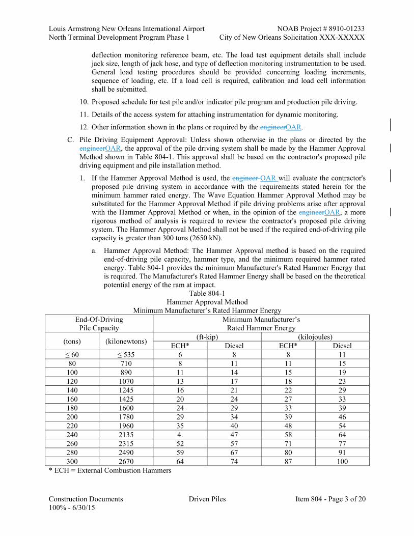
Louis Armstrong New Orleans International Airport NOAB Project # 8910-01233 North Terminal Development Program Phase 1 City of New Orleans Solicitation XXX-XXXXX
Construction Documents Driven Piles Item 804 - Page 3 of 20 100% - 6/30/15
deflection monitoring reference beam, etc. The load test equipment details shall include jack size, length of jack hose, and type of deflection monitoring instrumentation to be used. General load testing procedures should be provided concerning loading increments, sequence of loading, etc. If a load cell is required, calibration and load cell information shall be submitted.
10. Proposed schedule for test pile and/or indicator pile program and production pile driving.
11. Details of the access system for attaching instrumentation for dynamic monitoring.
12. Other information shown in the plans or required by the engineerOAR.
C. Pile Driving Equipment Approval: Unless shown otherwise in the plans or directed by the engineerOAR, the approval of the pile driving system shall be made by the Hammer Approval Method shown in Table 804-1. This approval shall be based on the contractor's proposed pile driving equipment and pile installation method.
1. If the Hammer Approval Method is used, the engineer OAR will evaluate the contractor's proposed pile driving system in accordance with the requirements stated herein for the minimum hammer rated energy. The Wave Equation Hammer Approval Method may be substituted for the Hammer Approval Method if pile driving problems arise after approval with the Hammer Approval Method or when, in the opinion of the engineerOAR, a more rigorous method of analysis is required to review the contractor's proposed pile driving system. The Hammer Approval Method shall not be used if the required end-of-driving pile capacity is greater than 300 tons (2650 kN).
a. Hammer Approval Method: The Hammer Approval method is based on the required end-of-driving pile capacity, hammer type, and the minimum required hammer rated energy. Table 804-1 provides the minimum Manufacturer's Rated Hammer Energy that is required. The Manufacturer's Rated Hammer Energy shall be based on the theoretical potential energy of the ram at impact.
Table 804-1 Hammer Approval Method
Minimum Manufacturer’s Rated Hammer Energy End-Of-Driving
Pile Capacity Minimum Manufacturer’s
Rated Hammer Energy
(tons) (kilonewtons) (ft-kip) (kilojoules)
ECH* Diesel ECH* Diesel ≤ 60 ≤ 535 6 8 8 11 80 710 8 11 11 15
100 890 11 14 15 19 120 1070 13 17 18 23 140 1245 16 21 22 29 160 1425 20 24 27 33 180 1600 24 29 33 39 200 1780 29 34 39 46 220 1960 35 40 48 54 240 2135 4. 47 58 64 260 2315 52 57 71 77 280 2490 59 67 80 91 300 2670 64 74 87 100
* ECH = External Combustion Hammers
NOAB Project # 8910-01233 Louis Armstrong New Orleans International Airport City of New Orleans Solicitation XXX-XXXXX North Terminal Development Program Phase 1
Item 804- Page 4 of 20 Driven Piles Construction Documents 100% - 6/30/15
b. Wave Equation Hammer Approval Method: Approval of the contractor's pile driving equipment will be based on the wave equation analysis computer program (FHWA-WEAP87 or newer version) and as required elsewhere in this subsection. A wave equation analysis will be performed by the Department OAR for each pile type and size required in the plans. Approval of the pile driving system does not relinquish the contractor's responsibility from driving the piles to the required pile tip elevation without damage.
1) The criteria the engineer OAR will use to evaluate the pile driving equipment from the wave equation shall be the pile driving resistance. The required number of hammer blows at the required end-of-driving pile capacity shall be from 36 to 146 blows per foot (30 to 120 blows per 0.25 m). The pile driving resistance at any depth above the required pile tip elevation shall be achieved with a reasonable driving resistance of less than 300 blows per foot (250 blows per 0.25 m).
2) Additional criteria that the engineer OAR will use for the pile driving equipment to be acceptable are the pile driving stresses that are indicated by the wave equation analysis to be generated during pile driving. The pile driving stresses shall not exceed the allowable values as required in Subsection 804.08(g).
3) When the wave equation analysis shows that the contractor's proposed equipment or methods will result in either the inability to drive the pile with a reasonable driving resistance to the desired pile bearing capacity or will exceed the maximum allowable pile driving stresses, the contractor shall modify or replace the proposed methods or equipment at his expense until subsequent wave equation analyses indicates that the contractor's proposed pile driving equipment and driving methods meet the required criteria for acceptability stated herein.
1.6 PILE DRIVING EQUIPMENT
A. Hammers: Piles may be driven with either diesel hammers or external combustion hammers (ECH) such as hammers driven by steam, air, or hydraulic power. Non-impact hammers such as vibratory hammers shall not be used unless specified in the plans or permitted in writing by the engineerOAR. Hammers shall be rated based on the theoretical potential energy of the ram at impact.
1. A variable energy hammer shall be used to drive precast concrete piles.
a. Steam and Air Hammers: Steam and air hammers that are used to drive precast concrete piles shall be capable of providing at least two ram stroke lengths. The short ram stroke length shall be approximately half of the full stroke. Reductions in steam or air pressures to produce reduced hammer strokes will not be permitted. In lieu of a variable energy hammer, the contractor may propose in the Pile Installation Plan the use of multiple hammers of different rated energies to drive precast concrete piles. The plant and equipment furnished for steam and air hammers shall have sufficient capacity to maintain the hammer at the volume and pressure specified by the manufacturer.
1) The plant and equipment shall be equipped with accurate pressure gauges that are easily accessible for viewing by the engineerOAR. The weight of the striking parts of air and steam hammers shall not be less than 1/3 the weight of drive head and pile being driven, and in no case shall the striking parts weigh less than 2,750 pounds (1250 kg).

Louis Armstrong New Orleans International Airport NOAB Project # 8910-01233 North Terminal Development Program Phase 1 City of New Orleans Solicitation XXX-XXXXX
Construction Documents Driven Piles Item 804 - Page 5 of 20 100% - 6/30/15
b. Open-End Diesel Hammers: Open-end diesel hammers used to drive precast concrete piles shall be capable of providing a selection of at least three fuel settings that will produce varying stroke lengths.
1) The contractor shall provide the engineer OAR a chart from the hammer manufacturer equating stroke in feet (m) and blows per minute. The contractor shall have available on-site an approved device to determine and display ram stroke in feet (m) of an open-end diesel hammer.
2) The device used to determine the hammer stroke shall be periodically verified as determined by the engineer OAR by comparing the computed hammer stroke with the observed stroke on rams that have rings on the ram or by placing a temporary scale extending above the ram cylinder.
c. Closed-End Diesel Hammers: Closed-end diesel hammers used to drive precast concrete piles shall be capable of providing a selection of at least three fuel settings that will produce varying stroke lengths.
1) Closed-end (double acting) diesel hammers shall be equipped with a bounce chamber pressure gauge mounted to be easily accessible by the engineerOAR. The contractor shall provide the engineer OAR a chart, calibrated to actual hammer performance, equating bounce chamber pressure to either equivalent energy or stroke for the closed-end diesel hammer to be used. The calibration between bounce chamber pressure and actual hammer performance should be performed within 30 calendar days prior to starting driving and at 90 calendar day intervals thereafter.
d. Hydraulic Impact Hammers: The power plant and equipment furnished for hydraulic hammers shall have sufficient capacity to maintain the hammer at the volume and pressure specified by the manufacturer. The power plant and equipment shall be equipped with accurate pressure gauges that are easily accessible to the OARengineer. These hammers shall be equipped with sensors or other approved devices capable of monitoring and displaying hammer performance.
e. Gravity Hammers: Gravity hammers, if permitted in the contract, shall only be used to drive timber piles. When gravity hammers are permitted, the ram shall weigh between 2,000 and 3,300 pounds (between 900 and 1500 kg) and the height of drop shall not exceed 10 feet (3 m). In no case shall the weight of gravity hammers be less than the combined weight of helmet and pile. All gravity hammers shall be equipped with hammer guides to ensure concentric impact on the helmet.
2. Drive System Components and Accessories:
a. Hammer Cushion: All impact pile driving equipment designed to be used with a hammer cushion shall be equipped with a suitable thickness of hammer cushion material to prevent damage to the hammer or pile and to ensure uniform driving behavior. Hammer cushions shall be made of durable, manufactured materials, provided in accordance with the hammer manufacturer's guidelines. Wood, wire rope, and asbestos hammer cushions shall not be used unless permitted by the OARengineer. A striker plate as recommended by the hammer manufacturer shall be placed on the hammer cushion to ensure uniform compression of the cushion material. The hammer cushion shall be inspected in the presence of the OARengineer when beginning pile driving at each structure and after every 100 hours of use during pile driving operations. The contractor shall replace the cushion when the hammer cushion begins

NOAB Project # 8910-01233 Louis Armstrong New Orleans International Airport City of New Orleans Solicitation XXX-XXXXX North Terminal Development Program Phase 1
Item 804- Page 6 of 20 Driven Piles Construction Documents 100% - 6/30/15
to deteriorate or when the reduction in thickness exceeds 25 percent of the original thickness.
b. Helmet: Piles driven with impact hammers require an adequate helmet or drive head to distribute the hammer blow to the pile head. The helmet shall be axially aligned with the hammer and the pile. The helmet shall be guided by the leads and not be free-swinging. The helmet shall fit around the pile head in such a manner as to prevent transfer of torsional forces during driving, while maintaining proper alignment of hammer and pile. For special types of piles, appropriate helmets, mandrels, or other devices shall be provided in accordance with the manufacturer's recommendations.
c. Pile Cushion: A pile cushion shall protect the heads of precast concrete piles. The pile cushion shall be made of plywood, hardwood, or a composite plywood and hardwood material. The minimum pile cushion thickness placed on the pile head prior to driving shall not be less than 4 inches (100 mm). The pile cushion dimensions shall match the cross sectional area of the pile top. A new pile cushion shall be provided for each pile driven unless otherwise permitted by the OARengineer. The pile cushion shall be replaced during pile driving when the cushion begins to deteriorate or burn. Pile bearing capacity shall not be determined using a new pile cushion until after the pile has been driven a minimum of 5 feet (1.5 m) or 100 blows.
1) When easy driving conditions exist throughout the entire depth of driving, the OARengineer may allow the pile cushion to be reused on several piles after guidelines for pile cushion replacement are developed from successful field performance. The objective shall be to maintain consistent energy delivery at the end-of-driving for proper determination of the pile bearing capacity without pile damage.
d. Leads: Piles shall be supported in line and position with leads while being driven. Pile driver leads shall be constructed in a manner that affords freedom of movement of the hammer while maintaining alignment of the hammer and the pile to ensure concentric impact for each blow. Leads may be either fixed, semi-fixed or swinging types. Swinging leads shall be used in combination with a rigid template providing pile support meeting the approval of the OARengineer. The pile section being driven shall not extend above the leads. The leads shall be of sufficient length to make the use of followers unnecessary and shall be so designed as to permit proper alignment of batter piles.
e. Templates: A rigid template shall be used when swinging leads are used. When driving battered piles with swinging leads, the template shall be two tiered or equipped with cradles to hold the pile at the required batter, and the bottom of the leads shall be attached to the template. Template construction shall allow the pile to pass freely through the template without binding.
1.7 PREPARATION FOR INSTALLATION OF DRIVEN PILES
A. Site Preparation:
1. Excavation: Piles shall not be driven until after the excavation is complete. Any material forced up between the piles shall be removed to the correct elevation before concrete for the foundation is placed.
2. Abutment (End Bent) Fill: The full height of the embankment at bridge ends shall be constructed in accordance with Subsection 813.03 before driving affected piles. Piles to be

Louis Armstrong New Orleans International Airport NOAB Project # 8910-01233 North Terminal Development Program Phase 1 City of New Orleans Solicitation XXX-XXXXX
Construction Documents Driven Piles Item 804 - Page 7 of 20 100% - 6/30/15
driven through compacted embankment greater than 6 feet (2 m) shall be driven through prebored holes limited in depth to the height of the embankment.
3. Cofferdams: Prior to driving any piles the contractor shall ensure the cofferdam is stable by monitoring the external stability of the ground outside of the cofferdam, wall inclination, and depth of excavation within the cofferdam. All excavation within the cofferdam shall be complete prior to driving piles. The depth of the excavation within the cofferdam shall be inspected for proper depth with a weighted line or other approved method.
4. Cone Penetrometer Test (CPT) Probings: The Cone Penetrometer Test (CPT) probings may be taken at all test pile and indicator pile locations, and at the CPT locations shown in the plans for production piling. The probings will be taken by the DepartmentOAR.
a. Tip elevations for test piles, indicator piles, and permanent piles given in the plans are for estimating purposes only. The final location and pile tip elevations for the test piles and indicator piles will be determined by the OARengineer from CPT probings. The final pile order lengths will be determined from the test pile or indicator pile results and the CPT probings.
b. The contractor shall make arrangements with the Department OAR to have the CPT probings taken at least 30 calendar days prior to driving test piles or indicator piles. When necessary, the contractor shall provide equipment to assist in moving the Cone Penetrometer Test truck around the site. The site for the probings shall be level as directed.
c. The contractor shall provide Type I portland cement (approximately ½ bag per probe hole) for use in grouting the CPT probe holes.Cone Penetrometer Test probing layout, supplying portland cement, and assistance will be at no direct pay.
B. Piling Preparation:
1. Transportation of Precast Concrete Piling: Precast concrete piles shall be supported adequately to prevent damage during transport.
2. Collars: Collars, bands, or other approved devices to protect timber piles against splitting or brooming shall be provided when necessary, or as required by the OARengineer.
3. Painting of Piling: When required by the plans or specifications, the foundation piling will be painted. The area of steel piles or the exterior surface of the steel shell of cast-in-place concrete piles, as specified in the plans shall be cleaned and painted from the top of the pile to a point 10 feet (3 m) below the ground or mudline. The paint system shall be a 2-coat coal tar epoxy-polyamide in accordance with Section 811.
4. Supporting Holes for Piles: When approved, piles may be set in supporting holes, but in no case shall the depth of the holes be more than 10 feet (3 m) for piles up to 50 feet (15 m) long, or more than 20 percent of the designated penetration of the piles for piles over 50 feet (15 m) long. If additional support is required, templates or falsework above ground shall be furnished. After piles are driven, supporting holes shall be backfilled to finished ground or base of footing with granular-type material acceptable to the OAR engineer and saturated with water.
5. Splicing Piles:
a. Precast Concrete Piles: Precast concrete piles shall be furnished and driven in full lengths, unless otherwise specified in the plans or approved in writing by the OARengineer. There will be no direct payment for splicing.
NOAB Project # 8910-01233 Louis Armstrong New Orleans International Airport City of New Orleans Solicitation XXX-XXXXX North Terminal Development Program Phase 1
Item 804- Page 8 of 20 Driven Piles Construction Documents 100% - 6/30/15
b. Steel Piles: Steel piles shall be furnished and driven in full lengths unless splices are authorized. Splices shall be limited to two field splices per pile. Splicing of steel piles shall be made by welding with full penetration welds in accordance with Section 815.
c. Timber Piles: Timber piles shall be furnished and driven full length.
d. Cast-In-Place Concrete Pile Shells: Cast-in-place concrete pile shells may be field spliced, but sections that, in the opinion of the OARengineer, are too short shall not be used. Field splices of shell sections shall be made in accordance with the manufacturer's recommendations and to the satisfaction of the OARengineer. Welding shall comply with Section 815, except that the prequalification test for field welders will not be required unless directed.
6. Pickup Straps: Pickup straps shall be cutoff and epoxy grouted prior to driving in coastal areas.
1.8 CONSTRUCTION REQUIREMENTS
A. Preboring: Preboring by augering, wet-rotary drilling, or other methods used to facilitate pile driving will not be permitted unless specified in the plans or required by the OARengineer. When the soil investigation or field trials indicate impenetrable material above the minimum pile tip elevation, preboring may be required to facilitate pile driving. The use of spuds to punch through impenetrable soil layers shall not be permitted without approval. The depth of the prebored hole shall be developed so as to minimize the pile skin friction disturbance and still be sufficient to permit pile installation to the required pile tip elevation. Preboring procedures shall be carried out in a manner that will not impair the capacity of the piles already in place or the safety of existing structures. The contractor shall develop the preboring depth limits based on the soil information obtained from soil boring logs or Cone Penetrometer Test probings and submit the limits to the OARengineer for approval. The maximum prebored depth shall be 3 feet (1 m) above pile tip elevation, unless otherwise directed. Prebored holes shall have a maximum diameter of 80 to percent of the pile diameter unless written approval to do otherwise is received from the OARengineer. The prebored hole diameter for tapered piles shall be determined by the OARengineer. Upon completion of the preboring, any voids around the pile shall be filled with granular-type material acceptable to the OARengineer and saturated with water. The contractor is responsible for any and all effects due to preboring.
B. Jetting: Jetting will not be permitted unless allowed in the plans or required by the OARengineer. Jetting will not be allowed in footings, header banks, or where stability of embankments or other structures would be endangered unless approved in writing by the OARengineer. When the soil investigation or field trials indicate impenetrable material above the minimum pile tip elevation, jetting may be required to facilitate pile driving. The jet pipe penetration limit shall be developed to minimize the pile skin friction disturbance and still be sufficient to permit pile installation to the required pile tip elevation. The contractor shall develop the jet pipe penetration limits based on soil information obtained from soil boring logs or Cone Penetrometer Test probings and shall submit the limits to the OARengineer for approval. The maximum jet penetration limit shall be 5 feet (1.5 m) above the required pile tip elevation. Extending the maximum jet penetration limit will require written approval by the OARengineer.
1. When water jets are permitted, the jetting procedures shall be carried out in a manner which will not impair the capacity of the piles already in place or the safety of existing structures or create a crater around the pile causing it to drift. The contractor shall be responsible for all damage to the site caused by unapproved or improper jetting operations. The number and size of jets and the volume and pressure of water at jet nozzles shall be sufficient to

Louis Armstrong New Orleans International Airport NOAB Project # 8910-01233 North Terminal Development Program Phase 1 City of New Orleans Solicitation XXX-XXXXX
Construction Documents Driven Piles Item 804 - Page 9 of 20 100% - 6/30/15
erode material adjacent to the pile but not disturb the soil bearing material within 5 feet (1.5 m) of the required pile tip penetration. The jetting plant shall have sufficient capacity to deliver at all times a pressure equivalent to at least 100 psi (700 kPa) at two 0.75 inches (19 mm) jet nozzles. One jet pipe will be allowed only when the contractor is pre-jetting a hole prior to placing and driving the pile or when driving is interrupted and the jet is placed inside a steel pipe pile or a voided concrete pile. A minimum of two jets will be required when piles are jetted and driven concurrently using external jets. When jetting and driving is required, the jets shall be above the advancing pile tip approximately 3 feet (1 m), or as approved by the OARengineer. Jetting operations shall cease when the jet penetration limit is reached, and the pile shall then be driven with the approved impact hammer to the final pile tip penetration. The pile bearing capacity shall be determined only from the results of driving after the jets have been withdrawn. The contractor shall control, treat if necessary, and dispose of all jet water in a manner satisfactory to the engineerOAR. Upon completion of jetting a pile, any voids around the pile shall be filled with granular-type material acceptable to the engineer OAR and saturated with water.
C. Followers and Underwater Hammers: Followers or underwater hammers shall only be used when approved in writing by the OARengineer. When a follower or underwater hammer is permitted, the first pile in each pile group and every tenth pile driven thereafter shall be sufficiently long to permit being driven without a follower or underwater hammer, to verify that adequate pile capacity is being attained to develop the desired end-of-driving pile capacity for the pile group. The determination of the pile bearing capacity shall be made in accordance with Subsection 804.10 using the driving results of the extended piles. No direct payment will be made for cut-off of these extended piles. The follower or underwater hammer and pile shall be held and maintained in equal and proper alignment during driving.
1. The follower shall be of such material and dimensions to permit the piles to be driven to the length determined necessary from the driving of the extended piles. The follower shall be provided with a socket or hood carefully fitted to the pile head to minimize energy losses and prevent pile damage.
D. Cast-In-Place Concrete Pile Construction: After shells are driven to the required pile tip elevation and any required reinforcing steel is placed, shells shall be filled with concrete subsequent to their inspection and approval. The contractor shall provide suitable light for inspection of each shell after it has been driven to the required penetration. The shell shall be cleaned of debris and pumped dry before placing concrete. Reinforcing steel shall be securely fastened together to form a rigid cage. Care shall be taken to hold reinforcement in position during filling of piles. Concrete blocks or suitable devices may be used to prevent displacement of the reinforcement cage. Piles shall be filled with concrete to the cut-off elevation. Concrete in the shell shall be vibrated from the lower end of the reinforcing cage to the top of pile. When reinforcing steel is not required, concrete in the top 10 feet (3 m) of the shell shall be vibrated. Driving of additional piles within a radius of 10 feet (3 m) of the completed pile will not be permitted until concrete has been allowed to set for at least 36 hours.
E. Location and Alignment Tolerance: Piles shall be driven at locations shown on the plans or as ordered in writing. In pile bents, the centroid of a pile at cut-off elevation shall not vary from plan location by more than 3 inches (75 mm) measured perpendicular to the bent, nor more than 6 inches (150 mm) measured along the centerline of the bent. For footing piles, the centroid of load of any pile at cut-off elevation shall be within a 6 inches (150 mm) radius of a circle having the plan location as its center. No pile shall be nearer than 3 inches (75 mm) from any edge of the cap. Any increases in size of cap to meet these edge distance requirements shall be at the contractor's expense. The final pile head at cut-off elevation shall be plus or minus 2 inches (50 mm) of the final grade shown in the plans. Piles shall be installed so that the axial

NOAB Project # 8910-01233 Louis Armstrong New Orleans International Airport City of New Orleans Solicitation XXX-XXXXX North Terminal Development Program Phase 1
Item 804- Page 10 of 20 Driven Piles Construction Documents 100% - 6/30/15
alignment is within 2 percent of the specified alignment shown in the plans. For piles that cannot be inspected internally after installation, an alignment check shall be made before installing the last 5 feet (1.5 m) of pile, or after installation is completed provided the exposed portion of the pile is not less than 5 feet (1.5 m) in length. The OARengineer may require that driving be stopped in order to check the pile alignment. Pulling laterally on piles to correct misalignment, or splicing a properly aligned section on a misaligned section shall not be permitted.
1. If the location and/or alignment tolerances specified herein are exceeded, the contractor shall provide the OARengineer with a sketch showing the actual versus theoretical positions of the piles. If corrective measures are necessary, the contractor shall bear all costs, including delays, associated with the corrective action.
F. Installation Sequence: The contractor's approved pile driving sequence to drive individual piles in a footing shall be used unless otherwise directed by the OARengineer. The pile driving sequence for individual piles in a footing shall be in accordance with one of the following options:
1. (1) From the center of the pile group outward.
2. (2) By rows from the center of the pile group to the side.
3. (3) By rows from one side of the pile group to the other side.
G. Pile Driving Stresses: The piles shall be driven in a manner as not to exceed the maximum allowable driving stresses. For steel piles, the maximum compressive driving stresses shall not exceed 90 percent of the yield point of the pile material. For timber piles, the compressive driving stress shall not exceed 3600 psi (25 MPa). For precast prestressed concrete piles, the tensile and compressive driving stress in units of psi (MPa) from Table 804-2 shall not be exceeded.
Table 804-2
Maximum Allowable Driving Stresses Tensile Driving Stress (Normal Environments):
U.S. Units 3 √f'c + fpe
Metric Units 0.25 √f'c + fpe
Tensile Driving Stress (Corrosive Environments): U.S. Units
fpe Metric Units
fpe Compressive Driving Stress (All Environments):
U.S. Units 0.85 f'c - fpe
Metric Unit 0.85 f'c - fpe
f'c = Concrete Compressive Strength, psi (MPa) fpe = Effective Prestress, psi (MPa)
1. The plans shall indicate if the allowable tensile driving stress of precastprestressed concrete piles shall be computed for corrosive environments. Pile driving criteria may be provided by the Geotechnical Engineer OAR to maintain pile driving stresses within the maximum allowable driving stresses.
H. Extent of Driving: Driving shall be continued until the OARengineer determines satisfactory penetration and pile bearing capacity have been obtained. Approval from the OARengineer shall be required to terminate pile driving above the plan tip elevation or order list pile tip

Louis Armstrong New Orleans International Airport NOAB Project # 8910-01233 North Terminal Development Program Phase 1 City of New Orleans Solicitation XXX-XXXXX
Construction Documents Driven Piles Item 804 - Page 11 of 20 100% - 6/30/15
elevation. Piles shall be driven to the plan tip elevation or the order list pile tip elevation in accordance with these specifications, unless a minimum pile tip is specified in the plans. If the pile penetration requirements and pile bearing capacity are achieved within 5 feet (1.5 m) of the plan pile tip elevation or order list pile tip elevation, the OARengineer may consider the penetration and capacity requirements to be satisfied. The following requirements shall be used to evaluate satisfactory pile penetration and pile bearing capacity.
1. Pile Driving Penetration Requirements: If refusal is encountered above the required plan pile tip elevation or order list pile tip elevation, the contractor may be required to obtain a larger hammer capable of achieving the required penetration, or to use pile installation techniques to facilitate pile driving such as preboring or jetting. Refusal conditions shall require that the approved hammer is operating at the maximum stroke or fuel setting required to achieve the hammer manufacturer's maximum rated energy. The hammer shall be in proper working order. If the hammer performance needs to be evaluated, the OARengineer may require dynamic monitoring of the pile driving operations. If the hammer performance indicates that the pile driving system's effective efficiency is not satisfactory, the contractor shall be required to adjust the pile driving system until satisfactory performance is observed. The cost of dynamic monitoring and/or delays due to unsatisfactory hammer performance shall be at the contractor's expense. Dynamic monitoring of hammers performing satisfactorily shall be paid for under the Item 804-17, Dynamic Monitoring.
2. Pile Bearing Capacity Requirements: The pile bearing capacity shall be determined in accordance with Subsection 804.10.
a. If pile bearing capacity is less than the required end-of-driving pile capacity at cut-off elevation, the OARengineer has the option of either loading a permanent pile to determine its ultimate pile capacity, continuing to drive the pile until satisfactory resistance is obtained, or perform a pile restrike to check for increase in pile bearing capacity due to soil set-up. The loading procedure of permanent piles shall be in accordance with Subsection 804.11. The additional length of pile due to the additional driving shall be furnished in accordance with the construction methods in Subsection 804.08(k) for pile extensions. Pile restrikes shall be performed in accordance with Subsection 804.08(i).
b. If the potential exists for obtaining false pile bearing capacity results due to excess pore water pressure or if this condition was observed during field testing of test piles, indicator piles, or monitor piles, the pile bearing capacity shall be determined from pile restrikes as directed by the OARengineer.
I. Pile Restrikes: Pile restrikes are to be conducted as required for test piles, indicator piles, and production piles or as directed by the OARengineer. Pile restrikes shall be conducted at no direct pay.
1. The piles to be restruck shall be driven initially to 1 foot (0.25 m) above the required pile tip elevation, or as directed by the OARengineer. All pile restrikes shall be performed with a warm hammer that has applied a minimum of 20 blows to another pile or dummy block immediately before being used to restrike the selected pile. For precast concrete piles, the original pile cushion used during initial driving shall be used. If the original pile cushion used to drive precast concrete piles is no longer in an acceptable condition, another similar used cushion shall be used. The maximum amount of pile penetration required for each pile restrike shall be 6 inches (150 mm) or a maximum of 50 hammer blows. If the required end-of-driving pile capacity is obtained during the restrike of permanent piles, the pile shall

NOAB Project # 8910-01233 Louis Armstrong New Orleans International Airport City of New Orleans Solicitation XXX-XXXXX North Terminal Development Program Phase 1
Item 804- Page 12 of 20 Driven Piles Construction Documents 100% - 6/30/15
be driven to grade. Restrike blow counts shall be measured as the number of hammer blows per increment of 1 inch (25 mm).
J. Heaved Piles: Elevations to check on pile heave after driving shall be made at the start of pile driving operations and shall continue until the OARengineer determines that such checking is no longer required. Elevations shall be taken immediately after the pile has been driven and again after piles within a radius of 15 feet (5 m) have been driven. If pile heave is observed, level readings referenced to a fixed datum shall be taken on all piles immediately after installation and periodically thereafter as adjacent piles are driven to determine the pile heave range. All end bearing piles that have been heaved more than 1/4 inch (6 mm) shall be redriven to the required resistance or penetration at no direct pay. Concrete shall not be placed in pile casings until all piles in a footing have been driven, or as directed by the OARengineer.
K. Pile Extensions:
1. Cast-In-Place Extension of Precast Concrete Piles: When permitted or shown on the plans, a precast pile may be extended a maximum of 5 feet (1.5 m) as shown on the plans. The plans show the length of reinforcing steel to be exposed and the additional size and number of reinforcing bars to be spliced where pile extensions are required. The final cut of the concrete shall be perpendicular to the axis of the pile. Concrete shall be as shown on the plans. Just prior to placing concrete, the top of the pile shall be thoroughly wetted and covered with a thin coating of neat cement or other suitable bonding material.
2. Steel Piles: When permitted or shown on the plans, a steel pile may be extended by splicing in accordance with Section 815.
L. Pile Cut-Offs:
1. Precast Concrete Piles: Cut-offs for precast concrete piles shall be made perpendicular to the axis of the pile at the elevation shown on the plans or as directed. Care shall be exercised to minimize spalling of concrete below the cut-off elevation.
2. Steel Piles: Steel piles shall be cut off perpendicular to the axis of the pile and to the elevation shown on the plans or as directed. Cuts shall be made in clean straight lines and any irregularity due to cutting or burning shall be corrected by grinding or deposits of weld material prior to placing caps.
3. Timber Piles: The tops of timber piling which support concrete footings or caps shall be sawed off perpendicular to their axes at the required elevation. When piles support timber caps they shall be sawed to a horizontal plane or to the slope specified, in such manner as to fit the cap. Shimming on tops of piles will not be permitted. Treatment of pile heads shall conform to Subsection 812.06.
4. Cast-in-Place Concrete Piles: After pile shells are fully driven, inspected, and approved, they shall be cut off perpendicular to the axis of the pile at the required elevation.
1.9 UNSATISFACTORY PILES
A. The procedure used in driving piles shall not subject them to excessive abuse which produces cracking, crushing or spalling of concrete, splitting, splintering and brooming of timber, or deformation of steel. Manipulation of precast concrete piles to force them into proper position will not be permitted. Any pile found to be unacceptable due to internal defects, by improper driving, driven out of proper location, or driven below required elevation shall be corrected at no direct pay by one of the following methods approved by the OARengineer:

Louis Armstrong New Orleans International Airport NOAB Project # 8910-01233 North Terminal Development Program Phase 1 City of New Orleans Solicitation XXX-XXXXX
Construction Documents Driven Piles Item 804 - Page 13 of 20 100% - 6/30/15
1. The pile shall be withdrawn and replaced by a new and, if necessary, a longer pile. Additional pile length and/or load testing may be required with no additional compensation due to disturbance of the soil from jetting or other methods used during removal of the pile.
2. A second pile shall be driven adjacent to the defective pile. This may require driving the replacement pile with a batter in order to place the pile head at the plan location.
3. The pile shall be spliced or built up as otherwise provided herein or a sufficient portion of the footing extended to embed the pile.
4. The cap or footing shall be redesigned at no direct pay and shall be approved by the OAR engineer. The contractor will not be allowed additional compensation for increased quantities in a bent or footing due to driving additional piles to correct unsatisfactory piles.
5. Cracks in concrete piles shall be corrected as follows:
a. Transverse cracks in piles that show evidence of spalling and or piles with diagonal or longitudinal cracks will be rejected unless the pile has required penetration and resistance and can be cut off below the crack and built up, or it can be repaired by other methods approved by the OARengineer.
b. Transverse cracks that show light dusting or powdering during driving shall be repaired by epoxy injection. Driving shall be stopped at the first sign of powdering and the crack shall be injected and cured in accordance with the epoxy manufacturer's recommendations before driving is resumed.
c. Concrete piles with minor hairline surface cracks will not be cause for rejection or repair provided no change in the crack condition occurs during driving.
1.10 DETERMINATION OF PILE BEARING CAPACITY
A. The pile bearing capacity is the pile capacity obtained during the end-of-driving or pile restrike. The pile bearing capacity determination shall be made by use of the Dynamic Formula, the Wave Equation, or the Test Pile Loading Results as specified in the plans. If the method of pile capacity is not shown on the plans the Dynamic Formula shall be used.
1. Dynamic Formula: The pile bearing capacity shall be determined by the OARengineer, based on the dynamic formula. Piles shall be driven with the approved pile driving equipment to the ordered length or other lengths necessary to obtain the required end-of-driving pile capacity. If the end of driving capacity is not shown on the plans the required pile bearing capacity shall be 3.5 times the pile design load.
English Dynamic Formula:

NOAB Project # 8910-01233 Louis Armstrong New Orleans International Airport City of New Orleans Solicitation XXX-XXXXX North Terminal Development Program Phase 1
Item 804- Page 14 of 20 Driven Piles Construction Documents 100% - 6/30/15
Metric Dynamic Formula:
2. Wave Equation: The pile bearing capacity shall be determined based on a wave equation analysis when required in the plans or directed by the OARengineer. Piles shall be driven with the approved pile driving equipment to the ordered length or other lengths necessary to obtain the required end-of-driving pile capacity. Approved methods to facilitate pile installation such as preboring, jetting, etc. shall be accounted for in the wave equation analysis.
1.11 FIELD TESTING PILES
A. When required, the contractor shall drive test piles, indicator piles, or monitor piles of the length, number, size and type specified at the location and penetration shown in the plans or as directed. These piles shall be driven using the approved pile driving system and the same pile installation method as will be used on permanent piles. Permanent piles may require field testing as directed by the OARengineer.
1. Ultimate Pile Capacity: The ultimate pile capacity is the pile capacity that has been determined from either a static or dynamic load test of a test pile, indicator pile, or permanent pile.
2. Test Piles: Test piles are piles that are driven in advance of the permanent piles for purposes of determining the length of foundation piles by static load testing. Test piles should be long enough to be redriven, if necessary, to the plan tip elevation of the piles at the nearest bent or as directed by the OARengineer. Test pile length shall be sufficiently long to permit static load testing and dynamic monitoring with the Pile Driving Analyzer. If the test pile is different than the anticipated permanent pile, prior approval must be received from the Chief, Construction Division. All test piles and/or indicator piles shall be inspected by DOTD Fabrication Inspectors prior to delivery to the project.

Louis Armstrong New Orleans International Airport NOAB Project # 8910-01233 North Terminal Development Program Phase 1 City of New Orleans Solicitation XXX-XXXXX
Construction Documents Driven Piles Item 804 - Page 15 of 20 100% - 6/30/15
3. Indicator Piles: Indicator piles are piles that are driven in advance of the permanent piles for purposes of determining the length of foundation piles by dynamic load testing. The difference between this type of pile and a test pile is that a static load test is not anticipated to be necessary. Indicator piles should be long enough to be redriven, if necessary, to the plan tip elevation of the piles at the nearest bent or as directed by the OARengineer. Indicator piles will have dynamic monitoring using the Pile Driving Analyzer.
4. Monitor Piles: Monitor Piles are permanent piles that are monitored during production pile driving for purposes of determining pile driving criteria by dynamic monitoring the pile driving installation. The Pile Driving Analyzer is used to evaluate the pile driving equipment and to monitor the pile driving stresses. This is usually accomplished by monitoring the first permanent pile of its type and size to be driven at each bridge structure or at a specified bent location. The monitor pile is paid for as a permanent pile.
5. Pile Restrikes: Pile restrikes for test piles, indicator piles, or monitor piles shall be performed in accordance with the time intervals specified below unless otherwise shown in the plans. Test piles that only have static load tests shall have a 1-day restrike after the initial pile installation. Test piles with dynamic monitoring shall have a 1-day restrike after the initial pile installation and a restrike within 24 hours after the load test with the Pile Driving Analyzer monitoring the driving. Indicator piles shall have a 1-day restrike and a 14-day restrike with the Pile Driving Analyzer monitoring the driving.
6. Test Site Preparation: When test piles and/or indicator piles are driven to determine the length of foundation piles or when a test pile is being driven on a stream bank where the most critical pile is in the middle of the stream, the test pile and/or indicator pile shall model the subsurface conditions of the permanent piles as directed. The contractor will be required to excavate the test pile location to the elevation of the bottom of the footing or stream and/or scour bottom and to keep this excavation open during driving and loading of test piles. In lieu of the above, the contractor will be permitted to drive the test pile within an approved metal casing. The casing shall extend and be excavated to the most critical elevation; be it the bottom of the footing, stream scour bottom, stream bottom, or elevation specified in the plans. The contractor shall provide any bracing or strengthening of the test pile required during loading or driving operations.
a. Cast-in-place concrete piles shall be filled with concrete in accordance with Subsection 804.08(d) and the concrete allowed to set for at least 48 hours and have attained a minimum concrete strength of 3400 psi (23.5 MPa) before commencing load testing.
7. Static Load Test: Test piles will be loaded at least 14 calendar days after initial driving unless otherwise directed by the OARengineer. All test pile loading results should be reviewed by the OARengineer to determine the ultimate pile capacity.
a. Loading Procedure: The load shall be applied in increments of 10 to 15 percent of the design load or as directed. Each load increment shall be held for an interval of 5 minutes. Gross settlement readings, loads, and other data shall be recorded by the OARengineer before and after the application of each load increment.
1) Test piles shall be loaded to failure or until 3 times the static load test pile capacity shown in the plans is reached. The test pile will be considered to have failed when continuous jacking is required to maintain the load and the pile is being driven into the ground. Unless otherwise directed, loading shall cease on a plunging pile when the gross settlement has reached 10 percent of the average pile diameter or diagonal dimension or as directed by the OARengineer. When the plunging load is reached, the loading system shall be allowed to equalize by taking readings at 5

NOAB Project # 8910-01233 Louis Armstrong New Orleans International Airport City of New Orleans Solicitation XXX-XXXXX North Terminal Development Program Phase 1
Item 804- Page 16 of 20 Driven Piles Construction Documents 100% - 6/30/15
minute increments until three consecutive readings indicate that the equilibrium load has been achieved.
2) The load shall be removed in decrements of approximately 25 percent of the maximum load placed on the test pile. Gross settlement and load readings shall be recorded 5 minutes after reaching each unloading load decrement. The final recovery of the unloaded test pile shall be recorded until movement is essentially complete for a period up to 30 minutes.
b. Load Testing System Approval: The load testing system shall be designed and constructed to allow vertical loads to be applied concentric with the longitudinal axis of the pile to be tested so that the load acting on the pile at any time may be accurately determined and controlled. To ensure concentric loading, a spherical bearing plate will be required to be mounted between the load frame and the pile head. The contractor shall submit for approval the proposed load testing system prepared and sealed by licensed civil engineer in the State of Louisiana. The plans shall include a detailed schematic of the load testing setup including steel bearing plates, load cell and bearing plates when required, hydraulic jack, reaction system, and reference system.
c. Hydraulic Jack: The contractor shall furnish hydraulic jacks of adequate size to deliver the required load and shall be equipped with a single gauge which shows the total pressure being applied. When 2 or more hydraulic jacks are used, they shall be connected in parallel by a manifold or other device used to direct the flow of fluid to the jacks. The calibrated pressure gauge shall be accurate to within five percent of the true load placed on the test pile. The contractor shall have the entire hydraulic system calibrated for all stages of loading and unloading by an approved independent calibration service. The calibration method shall take into account the travel that the ram in the hydraulic jack will undergo. The certified laboratory report of the calibration tests shall be furnished to the Materials and Testing Section for approval. After the system is calibrated, no replacement parts will be permitted (except the pump) without recalibration of the system.
d. Displacement Instrumentation: The contractor shall furnish instrumentation to monitor the gross displacement readings at the pile head during load testing. The instrumentation shall consist of two dial or electronic readout gauges capable of measuring displacement to a precision of ±0.001 inches (±0.025 mm), with a travel range of 3 inches (75 mm) or as directed. Smooth bearing surfaces perpendicular to the direction of the gauge-stem travel shall be provided for each gauge.
e. Load Cell: When specified in the plans, the contractor shall furnish the load cell. The load cell and bearing plates shall be of sufficient size and capacity to measure the maximum load being applied. The contractor shall have the load cell recalibrated by an approved testing laboratory if it has not been calibrated within the six months preceding the load test.
f. Reaction System: The reaction system shall be designed and constructed to resist the maximum anticipated test load.
1) Load Applied by Hydraulic Jack Acting Against Weighted Box or Platform: A test box or test platform resting on a suitable support shall be constructed over the test pile and loaded with earth, sand, concrete, metal or other suitable material with a total weight greater than the anticipated maximum test load. Supports for the weighted box or platform shall be located as far as practicable from the test pile but in no case less than a clear distance of 5 feet (1.5 m).

Louis Armstrong New Orleans International Airport NOAB Project # 8910-01233 North Terminal Development Program Phase 1 City of New Orleans Solicitation XXX-XXXXX
Construction Documents Driven Piles Item 804 - Page 17 of 20 100% - 6/30/15
2) Load Applied to the Test Pile by Hydraulic Jack Acting Against Anchored Reaction Member: Reaction member anchorages shall be constructed with a minimum clear distance of three times the maximum diameter of the reaction anchorages or test pile (whichever has the greater diameter) but not less than 7 feet (2 m). If permanent piles are used for anchorages, permanent piles shall be reseated after completion of test pile load test. Precast concrete piles shall not be used as anchorages. A member or members of sufficient strength to act as a rigid reaction beam shall be attached to the upper ends of the anchorages. Chains or cables shall not be used to transfer the reaction load to the anchorages.
3) Combination Devices: Load applied to the test pile by hydraulic jacks acting against a combination of devices (a) and (b) as described above.
4) Other Systems: Other systems may be proposed by the contractor for approval by the OARengineer.
g. Reference System: The contractor shall provide an independently supported reference beam. The reference beam shall consist of installing two wooden beams on each side of the test pile and braced internally to form a rigid frame. The frame will be supported at each end with sturdy timber stakes a minimum clear distance from the center of the test pile of three pile diameters or 8 feet (2.5 m) (whichever is longer). The reference beam supports shall be located as far as practical from reaction beam supports or anchorages. The reference beam supports shall be driven sufficiently deep to ensure that surface movement will not affect the lateral stability or vertical reference of the wooden frame.
h. Shelter: When specified in the plans or directed by the OARengineer, the contractor shall supply a temporary tent or shelter sufficient to cover the pile, reference beams, and displacement monitoring gauges from direct sunlight and rain during the load test.
i. Loading Permanent Piles: When the pile bearing capacity of a permanent pile in accordance with Subsection 804.10 is less than the test pile bearing capacity and will not correlate with the test pile data or is less than the required end-of-driving pile capacity shown in the plans, the OARengineer may direct the contractor to either drive permanent piles to a greater depth, restrike the pile after a specified waiting period, or load a permanent pile at the driven tip elevation. When loading a permanent pile is directed, the loading shall be conducted in accordance with the procedure given in Subsection 804.11(g) amended as follows. Permanent piles shall be loaded to failure or until a load equal to two times the design load plus any additional soil resistance required by the OAREngineer.
j. Dynamic Load Test: This work consists of assisting the Department OAR in obtaining dynamic measurements with the Department's LADTOD's Pile Driving Analyzer (PDA) of test piles, indicator piles, monitor piles, and permanent piles during initial pile driving and during pile restrikes. The cost of equipment mobilization or any delays due to dynamic monitoring shall be at no direct pay. When dynamic monitoring is specified, the piles shall be lengthened by a distance of 2.5 times the pile side dimension to allow access to the top of the pile at the end-of-driving. The dynamic monitoring shall be performed for the purpose of obtaining the ultimate pile capacity, pile driving stresses, pile integrity, and pile driving system efficiency.
1) Dynamic Monitoring Scheduling: The contractor shall give notice to the project engineerOAR at least 14 calendar days before the scheduled date of driving piles to be monitored. The contractor shall allow a possible three calendar day delay for any scheduling conflicts of the Department's LADTOD's Pile Driving Analyzer

NOAB Project # 8910-01233 Louis Armstrong New Orleans International Airport City of New Orleans Solicitation XXX-XXXXX North Terminal Development Program Phase 1
Item 804- Page 18 of 20 Driven Piles Construction Documents 100% - 6/30/15
personnel. The contractor shall confirm the driving date 3 working days prior to the scheduled driving date. The pile to be monitored and the contractor's pile driving equipment shall be on-site and at the location to be driven at least 24 hours prior to monitoring. The pile driving equipment shall be tested the day prior to dynamic monitoring to ensure that it is in proper working order. The project engineerOAR will notify the Pavement and Geotechnical Services Section to confirm that the pile and all associated pile driving equipment are on site, have been inspected and assembled, and are ready for driving operations at least 24 hours prior to dynamic monitoring. The contractor shall allow for a possible 7 day delay when rescheduling is required due to contractor delay.
2) Pile Driving Monitoring: The contractor shall furnish equipment, materials, and labor necessary for attaching the dynamic monitoring instrumentation. The contractor shall make the piles available prior to pile driving for drilling or tapping holes necessary to attach the instrumentation and take wave speed measurements. The contractor shall provide safe, stable, and OSHA approved access to the pile head for attaching the transducers after the pile is placed in the leads. A platform with a working area of not less than 16 square feet (1.5 sq m) shall be provided by the contractor and shall be equipped so that it may be raised to the top of the pile while the pile is located in the leads. Details of the access system for attaching instrumentation for dynamic monitoring shall be included in the pile installation plan. The expected delay for attaching the instruments to the pile will be approximately 1 hour. Occasionally, the pile driving may have to be temporarily interrupted for the transducers to be adjusted or replaced, or the monitoring results assessed. The contractor shall use reasonable care when working with the Pile Driving Analyzer instruments and accessories. The contractor shall be responsible for replacing any damaged equipment caused by the contractor.
3) During pile driving operations the Department OAR will monitor with the pile driving analyzer the pile driving stresses induced by the contractor's hammer to ensure that the pile is not being damaged. When necessary, the contractor shall reduce the driving energy transmitted to the pile.
k. Redriving Test Piles: When steel test piles or indicator piles fail to reach the required ultimate pile capacity, and redriving is required, steel bearing piles shall be extended by splicing if necessary, and redriven as directed. Precast concrete or cast-in-place concrete test piles or indicator piles shall not be extended and redriven. If directed, the contractor shall drive a new test pile to the designated depth at an approved location.
l. Test Pile and Indicator Pile Removal: If test piles or indicator piles are not to be used as permanent piles, they shall be removed to a minimum of 3 feet (1 m) below natural ground or stream bed and disposed of as directed.
1.12 MEASUREMENT
A. Pilings: Piling will be measured by the linear foot (lin m) of pile below pile cut-off elevation. Redriving of permanent piles used as load test anchorages in accordance with Subsection 804.11(g)(6)b will not be measured for payment.
B. Splices: Splices required to obtain order lengths will not be measured for payment.
C. Pile Extensions: No measurement will be made for extensions necessitated by damage to the pile during driving.

Louis Armstrong New Orleans International Airport NOAB Project # 8910-01233 North Terminal Development Program Phase 1 City of New Orleans Solicitation XXX-XXXXX
Construction Documents Driven Piles Item 804 - Page 19 of 20 100% - 6/30/15
1. Precast Concrete Piles: Measurement of extensions on precast concrete piles will be made by the linear foot (lin m). The length of cut-back on the ordered length of pile will be added to the net length of extension to obtain the gross length of extension. The gross length of extension will be multiplied by four to determine the quantity for payment. No deduction will be made from the ordered length of pile driven due to cut-back for splicing.
2. Steel Piles: Steel piles shall be measured to the linear foot (lin m). Measurement of extensions on steel piles will be made by the linear foot (lin m). The total number of linear feet (lin m) of piling driven will be determined by adding 2 feet (0.5 m) to the net length of piling for each authorized splice in place in the finished structure.
3. Other Piles: Measurement of extensions on other types of piles will be made by the linear foot (lin m) for that portion of the pile added to the original length of pile driven, which includes any additional driving required.
4. Cut-Offs: Cut-offs made as directed will be measured by the linear foot (lin m). Payment will not be made for cut-off of a pile unless the length of such cut-off is in excess of 1 foot (300 mm), nor will payment for cut-offs be made where they have been necessitated by crushing, brooming, splitting, or other damage resulting from driving. No payment will be made for required cut-offs of cast-in-place concrete pile shells. Such cut-offs will remain the property of the contractor.
5. Test Piles and Indicator Piles: The number of test piles and indicator piles to be paid for will be the number of piles of each type furnished and driven as directed. Cut-offs of test piles and indicator piles will not be included in any pay length. Test piles or indicator piles pulled and reused as permanent piles will be measured as provided under Heading (a) of this subsection.
6. Monitor Piles: Monitor piles will be measured under Heading (a) of this subsection. The field testing is paid for under the Dynamic Monitoring, Item 804-17.
7. Loading Test Piles: The number of test pile load tests to be paid for will be the number of load tests ordered and completed.
8. Loading Indicator Piles: The number of indicator pile load tests to be paid for will be the number of load tests ordered and completed.
9. Redriving Test Piles: Redriving of test piles or indicator piles will be measured for each test pile or indicator pile for which redriving is required.
10. Reloading Test Piles: The number of reload tests performed on test piles or indicator piles to be paid for will be the number of reload tests ordered and completed.
11. Loading Permanent Piles: The number of load tests to be paid for will be the number of load tests made as directed.
12. Dynamic Monitoring: The number of dynamic monitoring to be paid for will be the number of dynamic monitoring occurrences on test piles, indicator piles, monitor piles, and permanent piles ordered and completed. Dynamic monitoring occurrences that are necessary because of contractor error or required in accordance with Subsection 804.06(b)(3) shall not be measured for payment.
13. Prebored Holes and Jetting: Pilot holes and jetting will not be measured for payment.
1.13 PAYMENT

NOAB Project # 8910-01233 Louis Armstrong New Orleans International Airport City of New Orleans Solicitation XXX-XXXXX North Terminal Development Program Phase 1
Item 804- Page 20 of 20 Driven Piles Construction Documents 100% - 6/30/15
A. Piling: Payment for piling will be made at the contract unit price per linear foot (lin m), which includes all bolting, wrapping or fastening timber fender piles, driving batter piles, concrete and reinforcing steel, jetting or pilot holes, and redriving permanent piles used for anchor piles.
B. Pile Extensions: Payment for cast-in-place extensions will be made at the contract unit price per linear foot (lin m) for the type and size of pile extended.
C. Cut-Offs: Payment for cut-offs will be made at the contract unit price per linear foot (lin m).
D. Test Piles: Payment for test piles will be made at the contract unit price per each. Redriving of test piles will be paid for under Item 804-11.
E. Indicator Piles: Payment for indicator piles will be made at the contract unit price per each. Redriving of indicator piles will be paid for under Item 804-11. If it is determined from the driving records and the dynamic monitoring that the indicator pile should be load tested, each load test will be paid for under Item 804-09.
F. Loading Test Piles: Payment for loading test piles will be made at the contract unit price per each.
G. Redriving Test Piles: Payment for redriving test piles or indicator piles will be made at the contract unit price per each.
H. Reloading Test Piles: The number of reload tests to be paid for will be the number of reload tests ordered and completed.
I. Loading Permanent Piles: The number of load tests to be paid for will be the number of load tests made as directed.
J. Dynamic Monitoring: Payment for dynamic monitoring will be made at the unit price per each.
K. Payment will be made under:
Unit Price Pay items are listed in Section 01 22 00, Unit Price Pay Items. For Work not otherwise identified as being paid on Lump Sum basis, where no pay item is listed in Section 01 22 00, such work is considered subsidiary to other work, or incidental and will not be measured separately for payment.
END OF SECTION 804

Louis Armstrong New Orleans International Airport NOAB Project # 8910-01233 North Terminal Development Program Phase 1 City of New Orleans Solicitation XXX-XXXXX
Construction Documents Structural Concrete Item 805 - Page 1 of 24 100% - 6/30/15
SECTION 805 STRUCTURAL CONCRETE
1.1 DESCRIPTION
A. This work consists of furnishing, placing, finishing and curing portland cement concrete in bridges, culverts and other structures.
B. Quality assurance requirements shall be as specified in the latest edition of the Department's LADOTD's publication entitled "Application of Quality Assurance Specifications for Portland Cement Concrete Pavement and Structures" or "Application of Quality Assurance Specifications for Precast-Prestressed Concrete Plants."
C. Structural excavation and backfill shall conform to Section 802.
D. At the time of final acceptance, concrete box culverts constructed or extended by the contractor shall be cleaned of debris and soil to the culvert invert.
1.2 MATERIALS
A. Materials shall comply with the following Sections or Subsections:
Mortar 702.02 Steel Joints 807 Portland Cement Concrete 901 Joint Fillers 1005.01 Joint Sealants 1005.02-1005.06 Strip Seal Joints 1005.05 Waterstops 1005.07 Flexible Plastic Gasket Material 1006.06(b) Reinforcing Steel 1009 Epoxy Coated Reinforcing Steel and Repair Material
1009.01(e)
Curing Materials 1011.01 Special Surface Finish for Concrete 1011.03 Metals 1013 Precast Box Culvert Units 1016 Epoxy Resin Systems 1017.02 Prefabricated Masonry Pads 1018.06 Elastomeric Bridge Bearing Pads 1018.14 Form Release Agents 1018.24 Geotextile Fabric 1019
B. Classes of concrete furnished shall be as follows:
Table 805-1 Classes and Uses of Concrete
Concrete Class Use A or A(M) AA or AA(M) D
Concrete exposed to sea water, and all other concrete except as listed herein. Cast-in-place bridge superstructure Pier footings

NOAB Project # 8910-01233 Louis Armstrong New Orleans International Airport City of New Orleans Solicitation XXX-XXXXX North Terminal Development Program Phase 1
Item 805- Page 2 of 24 Structural Concrete Construction Documents 100% - 6/30/15
F P or P(M) P(X) R S
Dams and flood control structures Precast bridge members Precast-prestressed bridge girders Nonreinforced sections Underwater sections
1.3 HANDLING AND PLACING CONCRETE AND PRECAST UNITS
A. General: In preparation for placing concrete, all sawdust, chips and other debris shall be removed from the interior of forms. Struts, stays and braces serving to hold forms in correct shape and alignment shall be removed from the forms when concrete placing has reached an elevation rendering their use unnecessary.
1. Traffic shall not be permitted on bridge decks until concrete has been in place for 14 calendar days or has attained 3,500 psi (24.1 MPa) compressive strength. For concrete containing fly ash or ground granulated blast-furnace slag, the deck shall be closed to all traffic, including vehicles of the contractor, until the test specimens have attained a compressive strength of 3,500 psi (24.1 MPa).
2. Precast nonprestressed bridge unit shall be held at the plant a minimum of 10 calendar days after casting. After 10 calendar days, the units may be shipped, provided the required 28-day compressive strength has been attained.
3. Concrete shall be placed to avoid segregation of materials and displacement of reinforcement. The use of long troughs, chutes and pipes for conveying concrete from mixer to forms will be permitted only with written authorization. If these devices cause segregation, impede workability, or produce detrimental effects, their use shall be discontinued.
4. Open troughs and chutes shall be metal or metal-lined. Where steep slopes are required, chutes shall be equipped with baffles or be in short lengths that reverse the direction of movement of concrete.
5. Chutes, troughs and pipes shall be kept free from coatings of hardened concrete by thoroughly flushing with water after each pour. Water for flushing shall not be discharged within the structure.
6. When placing operations involve dropping concrete more than 5 feet (1.5 m), it shall be deposited through a sheet metal or other approved tremie. After initial set of the concrete, forms and any reinforcing bar projection shall not be disturbed.
7. Concrete, during and immediately after depositing, shall be thoroughly consolidated. Consolidation shall be done by mechanical vibration subject to the following provisions.
a. Vibration shall be internal unless authorization for other methods is obtained or as provided herein.
b. Vibrators shall be of an approved type and design, capable of transmitting vibration to concrete at frequencies of at least 4,500 impulses per minute.
c. Intensity of vibration shall be such as to visibly affect concrete over a radius of at least 18 inches (500 mm).
d. The contractor shall provide a sufficient number of vibrators to properly consolidate each concrete batch immediately after it is placed.

Louis Armstrong New Orleans International Airport NOAB Project # 8910-01233 North Terminal Development Program Phase 1 City of New Orleans Solicitation XXX-XXXXX
Construction Documents Structural Concrete Item 805 - Page 3 of 24 100% - 6/30/15
e. Vibrators shall be manipulated so as to thoroughly work concrete around reinforcement and imbedded fixtures and into corners and angles of forms.
1) Vibration shall be applied at the point of deposit and in the area of freshly deposited concrete. Vibrators shall be inserted and slowly withdrawn vertically from the concrete. Vibration shall be of sufficient duration and intensity to thoroughly compact concrete, but shall not cause segregation. Vibration shall not be continued at any one point to the extent that localized areas of grout are formed.
2) Application of vibrators shall be at points uniformly spaced and not farther apart than twice the radius over which vibration is visibly effective.
f. Vibration shall not be applied directly to or through reinforcement to sections or layers of concrete which have hardened to the degree that concrete ceases to be plastic under the vibration. It shall not be used to make concrete flow over distances so great as to cause segregation. Vibrators shall not be used to drag concrete in forms.
g. Vibration shall be supplemented by such spading as necessary to ensure smooth surfaces and dense concrete along form surfaces and in corners and locations inaccessible to vibrators.
h. These provisions for vibration shall apply to filler concrete for steel grid floor except that the vibrator shall be applied to the steel.
i. These provisions for vibration shall also apply to precast concrete except that, if approved, the manufacturer's methods of vibration may be used.
1) Concrete shall be placed in horizontal layers not more than 15 inches (375 mm) thick unless otherwise permitted. When less than a complete layer is placed in one operation, it shall be terminated at a vertical bulkhead. Each layer shall be placed and consolidated before the preceding batch has taken initial set to prevent damage to green concrete and avoid surfaces of separation between batches. The top surface of concrete adjacent to forms shall be finished to a suitable grade strip.
2) When concrete placement is temporarily discontinued, the concrete, shall be cleaned of laitance and other objectionable material to a sufficient depth to expose sound concrete after becoming firm enough to retain its form.
3) Where a featheredge might be produced at a construction joint, as in the sloped top surface of a wingwall, an inset form shall be used to produce a blocked out portion in the preceding layer which shall produce an edge thickness of not less than 6 inches (150 mm) in the succeeding layer. Placement of concrete shall not be discontinued within 18 inches (450 mm) of the top of any face, unless provision has been made for a coping less than 18 inches (450 mm) thick, in which case, the construction joint may be made at the underside of the coping.
4) Following concrete placement, accumulations of mortar splashed on reinforcement steel and forms shall be removed. Dried mortar chips and dust shall not be mixed in fresh concrete.
B. Reinforced Concrete Box Culvert: The contractor may furnish structures of either cast-in-place concrete or precast concrete units; however, design and installation procedures for precast units will be subject to approval. For the cast-in-place option, the base slab or footings of a box culvert shall be placed and allowed to set before the remainder of the culvert is constructed.

NOAB Project # 8910-01233 Louis Armstrong New Orleans International Airport City of New Orleans Solicitation XXX-XXXXX North Terminal Development Program Phase 1
Item 805- Page 4 of 24 Structural Concrete Construction Documents 100% - 6/30/15
1. Before concrete is placed in sidewalls, culvert footings shall be cleaned of shavings, sticks, sawdust and other debris and the surface carefully chipped or roughened in accordance with the method of bonding construction joints specified in Subsection 805.06.
2. For culverts 4 feet (1.2 m) or less in height, walls and top slab may be constructed monolithically. When this method of construction is used, necessary construction joints shall be vertical and perpendicular to the axis of the culvert.
3. In construction of box culverts more than 4 feet (1.2 m) in height, concrete in walls shall be placed and allowed to set in accordance with strength or curing time requirements of Subsection 805.11 before the top slab is placed.
4. If possible, each wingwall shall be constructed monolithically. Construction joints shall be horizontal and located so that no joint will be visible in the exposed face of the wingwall above the ground line.
5. Precast units shall be cast and placed as shown on the plans. Joints for sectional precast units shall comply with Subsection 1016.02. Joints shall be wrapped with an approved geotextile fabric for a minimum of 12 inches (300 mm) on each side of the joint. Ends of cloth shall be lapped at least 18 inches (450 mm), with the edges and ends suitably secured.
C. Girders, Slabs and Columns: Concrete in girders shall be deposited uniformly for the full length of girder and brought up evenly in horizontal layers.
1. Concrete in girder haunches less than 3 feet (900 mm) high shall be placed at the same time as that in the girder web; the column or abutment tops shall be cut back to form seats for the haunches. Whenever a haunch or fillet has a vertical height of 3 feet (900 mm) or more, the abutment or columns, haunch and girder shall be placed in three stages: up to the lower side of haunch, to the lower side of girder, and to completion. For haunched continuous girders, the girder web (including haunch) shall be placed to the top of web. Where the size of pour is such that it cannot be made in a continuous operation, vertical construction joints shall be located within the area of contraflexure.
2. Concrete in slab spans shall be placed in one continuous operation for each span.
3. Concrete columns shall be placed in a continuous operation. Concrete shall be allowed to set at least 24 hours before caps are placed. When friction collars are used to support cap forms, concrete columns shall have been poured at least 7 days or shall have at least 3,000 psi (20.7 MPa) compressive strength before caps are placed. Compressive strength cylinders shall be made in accordance with DOTD TR 226 and tested in accordance with DOTD TR 230.
4. No concrete shall be placed in the superstructure until column forms have been stripped sufficiently to determine the quality of concrete in the columns. The superstructure loads shall not be allowed on the bents until the concrete has attained at least 3,000 psi (20.7 MPa) compressive strength but not less than 7 curing days. Compressive strength cylinders shall be made in accordance with DOTD TR 226 and tested in accordance with DOTD TR 230.
D. Minimum Placement Rate for Bridge Decks: The contractor shall provide sufficient supervision, manpower, equipment, tools and materials to assure proper production, placement and finish of concrete for each pour in accordance with minimum placement rates specified in Table 805-2 below. If the contractor fails to meet the minimum placement rate, the engineer OAR may reject the pour; further placement of similar nature and size will not be permitted until corrective measures have been taken to assure that the minimum placement rate can be met.

Louis Armstrong New Orleans International Airport NOAB Project # 8910-01233 North Terminal Development Program Phase 1 City of New Orleans Solicitation XXX-XXXXX
Construction Documents Structural Concrete Item 805 - Page 5 of 24 100% - 6/30/15
Table 805-2
Concrete Placement Rates for Bridge Decks Pour Size
Cubic Yards (Cu m) Minimum Placement Rate
Cubic Yards (Cu m) Per Hour 0-50 (0-40)
51-75 (41-60) 76-125 (61-100)
Over 125 (Over 100)
20 (15) 25 (20) 30 (25) 40 (30)
1. Pour rates shown are intended for use on simple spans. For all spans, pours are to be completed in four hours. For continuous precast concrete girder spans, the pour rate is based on the volume of concrete in two adjacent spans divided by four hours.
E. End-On-Construction: The use of end-on-construction will only be allowed for slab span bridges, either cast-in-place concrete or precast concrete, when the construction cannot be conducted from the ground or it is impractical to work from the water surface. The contractor shall make a written request to the Department OAR for approval to use end-on-construction procedures. The contractor shall submit drawings and calculations with his request showing the construction loads to be placed on the structure. The drawings shall also show details of matting systems, crane size, outline dimensions, lifting loads, and extension distance from the crane. The calculations shall analyze the maximum construction loads, including structure dead loads, being applied to the structure. The drawings and calculations shall be stamped and signed by a professional civil engineer registered in the State of Louisiana.
1. No end-on-construction activity will be allowed on the structure until approved by the DepartmentOAR. Approval of end-on-construction procedures will not relieve the contractor from responsibility for repairing any damages to the structure, at no cost to the DepartmentOwner, caused by his construction activities.
1.4 PUMPING
A. Pumping equipment shall be so arranged that no vibrations result which might damage freshly placed concrete. Pipes carrying concrete to placing area shall be laid out with a minimum of bends and no unauthorized change in size. Where concrete is conveyed and placed by mechanically applied pressure, suitable equipment of adequate capacity shall be used.
1. A grout mortar, or concrete without coarse aggregate, shall be pumped through the equipment ahead of the regular concrete to provide lubrication to start pumping operations. This material shall not be used in placement. The lubrication process need not be repeated as long as pumping operations are continuous.
2. Operation of the pump shall be such as to provide a continuous stream of concrete without air pockets. When pumping is completed, concrete remaining in the pipes, if it is to be used, shall be ejected in such manner that there will be no contamination of concrete or separation of ingredients.
1.5 DEPOSITING CONCRETE UNDERWATER
A. Concrete shall not be deposited in water except on approval. The method of placing shall be approved by the engineer OAR and conform to the following:

NOAB Project # 8910-01233 Louis Armstrong New Orleans International Airport City of New Orleans Solicitation XXX-XXXXX North Terminal Development Program Phase 1
Item 805- Page 6 of 24 Structural Concrete Construction Documents 100% - 6/30/15
B. To prevent segregation, concrete shall be placed in its final position by means of a tremie and shall not be disturbed after being deposited. Concrete shall be placed in caissons, cofferdams or watertight forms.
C. For underwater parts of structures, concrete seals shall be placed in one continuous operation. The surface of the concrete shall be kept as nearly horizontal as possible; still water shall be maintained at the point of deposit.
D. A tremie shall consist of a tube at least 10 inches (250 mm) in diameter; if constructed in sections, the couplings shall be watertight. Tremies shall be supported so as to permit positioning anywhere over the top surface of the work and for rapid lowering when necessary to retard or stop the flow of concrete.
E. When concrete is dumped into the hopper, flow may have to be induced by slightly raising the discharge end of the tremie, but always keeping it in deposited concrete. Flow shall be continual until the work is completed. Aluminum tremies will not be permitted.
F. Dewatering may proceed when the concrete is sufficiently hard, but not for at least 72 hours after concrete placement is completed. Prior to constructing succeeding portions of the structure, laitance or other unsatisfactory material shall be removed from the surface by scraping, chipping or other means which will not damage the concrete.
1.6 CONSTRUCTION JOINTS
A. General: Construction joints shall be made only where located on the plans or shown on the pouring schedule, unless otherwise approved. When not detailed on the plans, construction joints shall be placed as directed. Raised shear keys or reinforcing steel shall be used where necessary to transmit shear or bond sections together.
B. Bonding: Forms shall be retightened before placing new concrete on or against hardened concrete.
1. Neat Cement Slurry Joints: The surface of hardened concrete shall be roughened as required in a manner that will not leave loosened particles of aggregate or damaged concrete at the surface. It shall then be thoroughly cleaned of foreign matter and laitance, and saturated with water. All surfaces shall be thoroughly coated with a neat slurry to ensure that adequate mortar is placed at the juncture of the hardened and newly deposited concrete. New concrete shall be placed before the grout has attained its initial set. Placing of concrete shall be carried continuously from joint to joint. Edges of joints which are exposed to view shall be finished true to line and elevation.
2. Epoxy Resin Joints: Vertical surfaces of bridge deck construction joints and other construction joints shall be coated prior to each succeeding pour with an approved Type II, Grade B or Grade C epoxy resin applied according to the manufacturer's recommendations. Surfaces of hardened concrete to which new concrete is to be bonded shall be cleaned of foreign material, loose or unsound concrete by sandblasting, hammers or wire brushes. Grease or oil shall be removed with a detergent wash such as trisodium phosphate, and the entire area washed with fresh water and brushed with a stiff brush. If a detergent is not required, dust and small particles not removed by other cleaning methods shall be removed by washing.
3. Unless a joint type (1) or (2) above is specified in the plans or specifications, the surface of the hardened concrete shall be thoroughly cleaned of foreign matter and laitance, and saturated with water prior to pouring fresh concrete.
1.7 CONCRETE EXPOSED TO SALT WATER

Louis Armstrong New Orleans International Airport NOAB Project # 8910-01233 North Terminal Development Program Phase 1 City of New Orleans Solicitation XXX-XXXXX
Construction Documents Structural Concrete Item 805 - Page 7 of 24 100% - 6/30/15
A. Concrete shall be thoroughly consolidated and stone pockets shall be avoided. No construction joints shall be formed between levels of extreme low water and extreme high water. Salt water shall not come in contact with concrete for at least 30 calendar days.
1.8 FALSEWORK
A. Detailed plans for falsework shall be furnished in accordance with Section 801.
1. Falsework shall be designed in accordance with Subsection 801.04.
2. Falsework which cannot be founded on a satisfactory footing shall be supported on piling spaced, driven and removed in an approved manner. Falsework shall be set to give the finished structure the specified camber.
1.9 FORMS
A. Construction: Forms shall be of wood, metal or other approved material, built mortartight and of sufficient rigidity to prevent distortion due to pressure of concrete and other loads incident to construction operations.
1. Forms shall be constructed and maintained to prevent warping and opening of joints due to shrinkage of lumber. Forms shall be substantial and unyielding and so designed that finished concrete will conform to proper dimensions and contours. Design of forms shall take into account the effect of vibration of concrete as it is placed.
B. Form Surface: Forms for exposed surfaces shall not adhere to nor discolor concrete. Forms shall be made of either metal or dressed lumber of uniform thickness with or without approved form liner and shall be mortartight. Forms for reentrant angles shall be chamfered and forms shall be filleted at sharp corners. Forms for projections, such as girders or copings, shall be given a bevel or draft to ensure easy removal.
1. When possible, forms shall be daylighted at intervals not greater than 10 feet (3 m) vertically, the openings being sufficient to permit free access for inspecting, working and spading the concrete.
C. Form Ties: Metal ties or anchorages within forms shall be constructed to permit their removal to a depth of at least 1/2 inch (13 mm) from the face without damage to concrete. If wire ties are permitted, upon removal of the forms, wire shall be cut back at least 1/4 inch (6 mm) inside from the face of the concrete with chisels or nippers. Fittings for metal ties shall be of such design that, upon their removal, cavities left will be of the smallest possible size. Cavities shall be filled with cement mortar and the surface left sound, smooth, even and uniform in color.
1. Fiberglass ties may be used and shall be ground flush with the concrete surface.
D. Setting and Maintaining: Forms shall be set and maintained reasonably true to required line and grade until concrete is sufficiently hardened. When forms are deemed to be unsatisfactory, either before or during placing of concrete, the work shall be stopped until defects have been corrected. Forms shall be so designed that portions where finishing is required may be removed without disturbing portions of forms to be removed later and, as far as practical, so that form marks will conform to general lines of the structure. For narrow walls and columns, where the bottom of the form is inaccessible, lower form boards shall be left loose so that they may be removed for cleaning out immediately before placing concrete.
E. Re-Used Forms: Shape, strength, rigidity, mortar-tightness and surface smoothness of re-used forms shall be maintained. Warped or bulged lumber shall be resized before being reused. Unsatisfactory forms shall not be re-used.

NOAB Project # 8910-01233 Louis Armstrong New Orleans International Airport City of New Orleans Solicitation XXX-XXXXX North Terminal Development Program Phase 1
Item 805- Page 8 of 24 Structural Concrete Construction Documents 100% - 6/30/15
F. Surface Treatment: Forms shall be treated with an approved form release agent prior to placement of reinforcing steel. Release agents which will adhere to or discolor concrete shall not be used. Prior to placing concrete, the interior of forms shall be cleaned of dirt, sawdust, shavings or other debris. Forms shall be inspected then saturated with water immediately prior to placing concrete.
G. Steel Stay-in-Place Forms: Steel stay-in-place forms can only be used when approved by the DOTD Chief Construction EngineerOAR. Steel stayin- place forms shall conform to the requirements of Subsection 1013.25. The dead load deflection of steel stay-in-place forms shall not exceed L/240 or 3/8 inch (9 mm). Concrete admixtures or set accelerators containing chlorides will not be allowed in the concrete when placed against steel stay-in-place forms.
1. When allowed, the use of steel stay-in-place forms will require:
a. Reinforcing chairs made for use with stay-in-place forms that will span the corrugations and properly support the reinforcing steel.
b. Metal chairs in contact with the metal forms shall be hot-dipped galvanized, electroplated with zinc (GS Grade), epoxy coated, or made of stainless steel.
c. Repair of any damage to galvanized surfaces on the metal pans or the visually exposed surfaces of the support angles with a cold galvanizing compound from QPL 23.
d. Removal of any portion of the support angle leg that sticks up into the bottom of the deck by more than 1/2 inch (13 mm).
e. Steel girders and stringers to be shielded to prevent weld splatter or arc strikes on them during the installation of the support angles.
f. Contractor responsible for any additional temporary bracing requirement to prevent rotation of exterior girders.
1.10 CURING
A. Concrete in substructures for grade separation structures, superstructures of major structures, and railroad underpasses shall be cured with wet burlap or combined wet burlap and white polyethelene sheeting. Precast concrete shall be cured in accordance with Subsection 805.14(e).
1. A Type 1-D curing compound complying with Subsection 1011.01 may be used for curing concrete in minor drainage structures and bridge substructures and diaphragms when surfaces do not require a Class 2A finish. When membrane curing is used, exposed reinforcing steel and construction joint surfaces shall be covered or shielded to prevent coating with curing compound. Construction joint surfaces shall be wet cured by approved methods as soon as possible after concrete placement. Concrete surfaces in contact with forms shall be sealed immediately after completion of form removal and surface finishing. Membrane curing shall be applied as soon as surface moisture has evaporated. Method and application rate of curing compound shall be in accordance with the manufacturer's recommendations, but in no case shall the application rate be less than one gallon per 100 square feet (one liter per 2.5 sq m) surface area. The compound shall be applied in one or two applications. If the compound is applied in two increments, the second application shall follow the first application within 30 minutes. Satisfactory equipment shall be provided, with means to properly control and direct application of curing compound on concrete surfaces to result in uniform coverage.
2. If rain falls on newly coated concrete before the film has dried sufficiently to resist damage, or if the film is damaged, a new coat of compound shall be applied to affected portions.
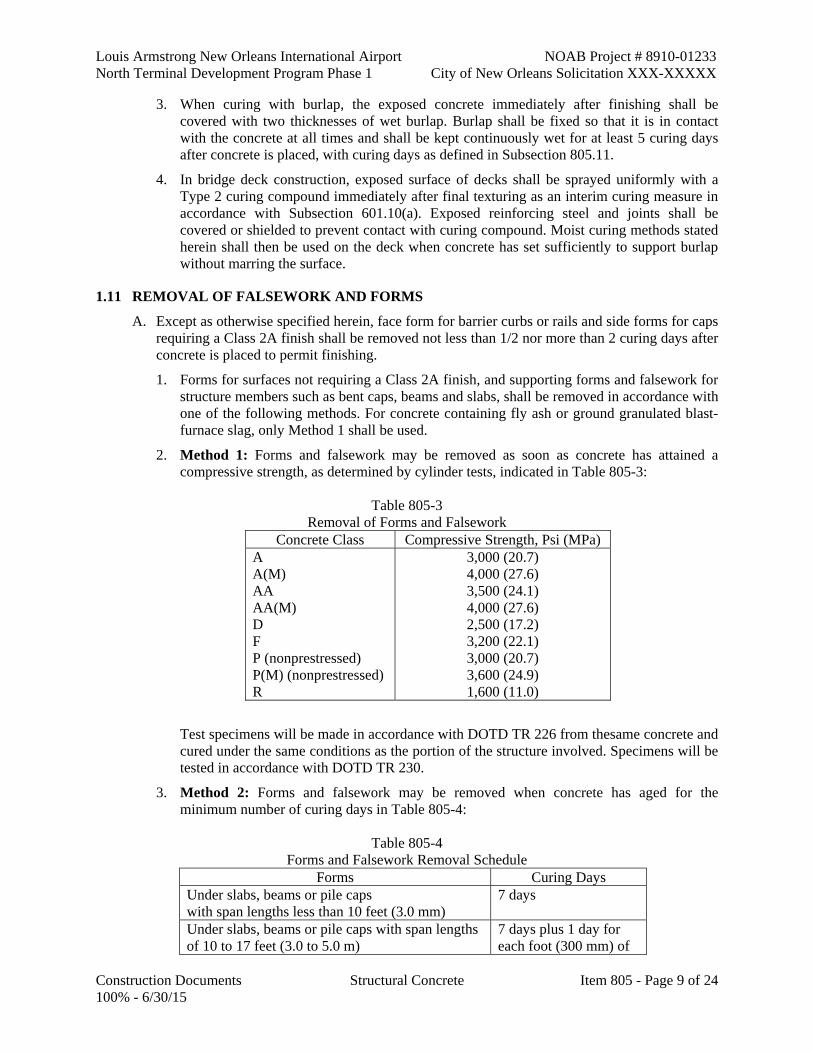
Louis Armstrong New Orleans International Airport NOAB Project # 8910-01233 North Terminal Development Program Phase 1 City of New Orleans Solicitation XXX-XXXXX
Construction Documents Structural Concrete Item 805 - Page 9 of 24 100% - 6/30/15
3. When curing with burlap, the exposed concrete immediately after finishing shall be covered with two thicknesses of wet burlap. Burlap shall be fixed so that it is in contact with the concrete at all times and shall be kept continuously wet for at least 5 curing days after concrete is placed, with curing days as defined in Subsection 805.11.
4. In bridge deck construction, exposed surface of decks shall be sprayed uniformly with a Type 2 curing compound immediately after final texturing as an interim curing measure in accordance with Subsection 601.10(a). Exposed reinforcing steel and joints shall be covered or shielded to prevent contact with curing compound. Moist curing methods stated herein shall then be used on the deck when concrete has set sufficiently to support burlap without marring the surface.
1.11 REMOVAL OF FALSEWORK AND FORMS
A. Except as otherwise specified herein, face form for barrier curbs or rails and side forms for caps requiring a Class 2A finish shall be removed not less than 1/2 nor more than 2 curing days after concrete is placed to permit finishing.
1. Forms for surfaces not requiring a Class 2A finish, and supporting forms and falsework for structure members such as bent caps, beams and slabs, shall be removed in accordance with one of the following methods. For concrete containing fly ash or ground granulated blast-furnace slag, only Method 1 shall be used.
2. Method 1: Forms and falsework may be removed as soon as concrete has attained a compressive strength, as determined by cylinder tests, indicated in Table 805-3:
Table 805-3
Removal of Forms and Falsework Concrete Class Compressive Strength, Psi (MPa)
A A(M) AA AA(M) D F P (nonprestressed) P(M) (nonprestressed) R
3,000 (20.7) 4,000 (27.6) 3,500 (24.1) 4,000 (27.6) 2,500 (17.2) 3,200 (22.1) 3,000 (20.7) 3,600 (24.9) 1,600 (11.0)
Test specimens will be made in accordance with DOTD TR 226 from thesame concrete and cured under the same conditions as the portion of the structure involved. Specimens will be tested in accordance with DOTD TR 230.
3. Method 2: Forms and falsework may be removed when concrete has aged for the minimum number of curing days in Table 805-4:
Table 805-4
Forms and Falsework Removal Schedule Forms Curing Days
Under slabs, beams or pile caps with span lengths less than 10 feet (3.0 mm)
7 days
Under slabs, beams or pile caps with span lengths of 10 to 17 feet (3.0 to 5.0 m)
7 days plus 1 day for each foot (300 mm) of

NOAB Project # 8910-01233 Louis Armstrong New Orleans International Airport City of New Orleans Solicitation XXX-XXXXX North Terminal Development Program Phase 1
Item 805- Page 10 of 24 Structural Concrete Construction Documents 100% - 6/30/15
span over 10 feet (3 m) Under slabs, beams or pile caps with span lengths over 17 feet (5.0 m)
14 days
Under portion of slabs that cantilever more than 1 foot (300 mm)
7 days
Walls, columns, side forms for beams, pile caps and slabs that cantilever less than 1 foot (300 mm)
1 day
Caissons 1 day Precast nonprestressed bridge units (side forms) 1 day
4. The term "curing day" will be interpreted as a calendar day on which the temperature is above 50°F (10°C) or 55°F (13°C) if ground granulated blast furnace slag is used in concrete for at least 19 hours. Colder days may be counted if approved methods are used to maintain air temperature adjacent to concrete above 50°F (10°C) throughout the day.
5. During continued cold weather, when artificial heat is not provided, the engineer OAR may permit removal of forms and falsework at the end of a period of calendar days equal to two times the number of curing days stated above.
6. The foregoing provisions for form and falsework removal shall apply only to forms or parts of forms so constructed as to permit removal without disturbing forms or falsework which are required to be left in place for a longer period on other portions of the structure.
7. Methods of form removal likely to cause overstressing of concrete shall not be used. Forms and their supports shall not be removed without approval. Supports shall be removed in such manner as to permit concrete to uniformly and gradually take stresses due to its own weight.
1.12 EXPANSION AND FIXED JOINTS, AND BEARINGS
A. Open Joints: Open joints shall be constructed by insertion and subsequent removal of a wood strip, metal plate or other approved material. Insertion and removal of the template shall be accomplished without chipping or breaking corners of concrete. Reinforcement shall not extend across an open joint.
B. Filled Joints: Joints to be sealed with poured seals shall be formed and constructed similar to open joints. For joints with preformed filler, the filler shall be in correct position when concrete is placed.
C. Joint Seals: Joints shall be sealed full width, including curbs and sidewalks. The concrete shall be at least seven days old prior to sealing. Liquid poured or silicone sealant may be used, however the same type sealant shall be used for the entire structure.
1. Liquid Poured: Before application of the sealant, joint faces shall be sandblasted. Joints shall be thoroughly dry at the time of installation. Sealants shall be installed in accordance with the manufacturer's recommendations. The material's shelf life shall not be exceeded. The ambient air temperature at the time of application shall be at 70°F (20°C) or greater. Application shall be done by a machine with a powered mixing device with an accurate method of proportioning and mixing the components.
a. Primers, when required, shall be applied as directed by the manufacturer; however, it shall be applied the same day as installation and shall be tack free prior to installation of sealants.

Louis Armstrong New Orleans International Airport NOAB Project # 8910-01233 North Terminal Development Program Phase 1 City of New Orleans Solicitation XXX-XXXXX
Construction Documents Structural Concrete Item 805 - Page 11 of 24 100% - 6/30/15
b. Joints shall be backed with an approved backer material. Prior to cleaning the joint faces, the top of the joint filler shall be removed to a depth to allow for placement of the backer material, joint sealant, and sealant recess below the finished surface. The backer material shall be compressed into the joint such that it adheres tightly to the sides of the joint.
2. Silicone Sealant: The silicone sealant shall comply with Subsections 1005.02(c) or (d). The joint faces shall be sandblasted prior to sealing, and the faces shall be dry and dust free at the time of installation. The silicone sealant shall be installed in accordance with the manufacturer's recommendations, and the air temperature at the time of placement shall be at least 50°F (10°C). The sealant material shall be tooled by approved methods to force the material against the joint walls.
a. Joints shall be backed with an approved backer material. Prior to cleaning the joint faces, the top of the joint filler shall be removed to a depth to allow for placement of the backer material, joint sealant, and sealant recess below the finished surface. The backer material shall be compressed into the joint such that it adheres tightly to the sides of the joint.
D. Strip Seal Joints: Joints shall be free of loose rust, and thoroughly clean and dry at the time of installation. Joint seal glands shall be installed in accordance with the manufacturer's recommendations.
1. Stretching of the seal gland shall be minimal. When installation procedures appear to cause stretching, random inspection will be made. Frequency and thoroughness of inspections shall be as directed. Maximum allowable stretch shall be 5 percent. When maximum limits are exceeded, and the adhesive lubricant has chemically set, the seal shall be completely removed and cleaned, the joint recleaned and reinstallation made at no direct pay.
2. The adhesive lubricant shall be applied just prior to installation of the gland and shall be sufficient to completely cover the contact surfaces of the steel extrusion and the seal glands. Installation shall be done in a manner that least disturbs the adhesive lubricant. Dilution of the adhesive lubricant will not be allowed.
3. The joint manufacturer shall submit shop drawings in accordance with Subsection 801.03 and shall supervise the installation and provide the necessary technical expertise.
4. Welding shall be in accordance with Section 815. Shop fabrication and fabrication inspection shall conform to Section 807.
5. Temporary restraints placed in joints shall be removed as soon as possible after placing concrete adjacent to the joint.
E. Preformed Polyurethane Expansion Joint Filler: Joint fillers shall be installed as directed.
F. Steel Joints: Plates, angles or other structural shapes shall be fabricated to conform to the plans and section of the concrete floor. The surface in the finished plane shall be true and free of warping. Positive methods shall be employed in placing joints to keep them in correct position during placing of concrete. The opening at expansion joints shall be designated on the plans at the prescribed temperature. The required clearance shall be accurate considering temperature effects and stage of construction at the time of installation.
1. Temporary restraints placed in joints shall be removed as soon as possible after placing concrete adjacent to the joint.
G. Waterstops: Adequate waterstops of metal, rubber or plastic shall be placed as shown on the plans. Where joint movement is to be provided, waterstops shall be of a type permitting such
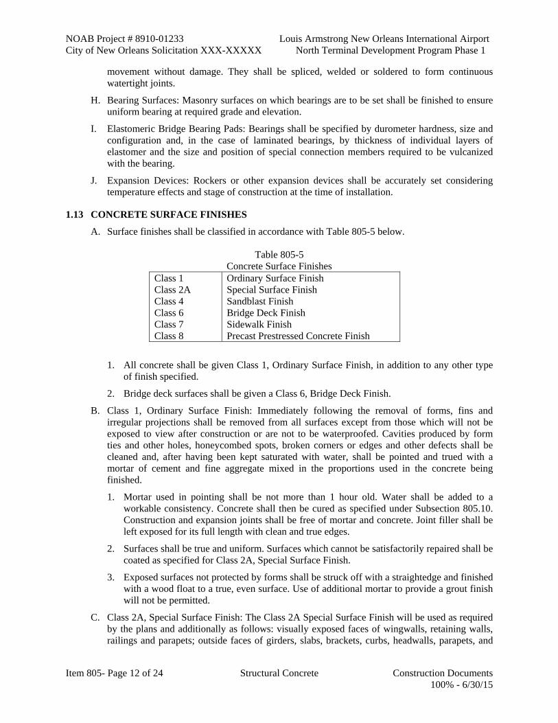
NOAB Project # 8910-01233 Louis Armstrong New Orleans International Airport City of New Orleans Solicitation XXX-XXXXX North Terminal Development Program Phase 1
Item 805- Page 12 of 24 Structural Concrete Construction Documents 100% - 6/30/15
movement without damage. They shall be spliced, welded or soldered to form continuous watertight joints.
H. Bearing Surfaces: Masonry surfaces on which bearings are to be set shall be finished to ensure uniform bearing at required grade and elevation.
I. Elastomeric Bridge Bearing Pads: Bearings shall be specified by durometer hardness, size and configuration and, in the case of laminated bearings, by thickness of individual layers of elastomer and the size and position of special connection members required to be vulcanized with the bearing.
J. Expansion Devices: Rockers or other expansion devices shall be accurately set considering temperature effects and stage of construction at the time of installation.
1.13 CONCRETE SURFACE FINISHES
A. Surface finishes shall be classified in accordance with Table 805-5 below.
Table 805-5 Concrete Surface Finishes
Class 1 Class 2A Class 4 Class 6 Class 7 Class 8
Ordinary Surface Finish Special Surface Finish Sandblast Finish Bridge Deck Finish Sidewalk Finish Precast Prestressed Concrete Finish
1. All concrete shall be given Class 1, Ordinary Surface Finish, in addition to any other type of finish specified.
2. Bridge deck surfaces shall be given a Class 6, Bridge Deck Finish.
B. Class 1, Ordinary Surface Finish: Immediately following the removal of forms, fins and irregular projections shall be removed from all surfaces except from those which will not be exposed to view after construction or are not to be waterproofed. Cavities produced by form ties and other holes, honeycombed spots, broken corners or edges and other defects shall be cleaned and, after having been kept saturated with water, shall be pointed and trued with a mortar of cement and fine aggregate mixed in the proportions used in the concrete being finished.
1. Mortar used in pointing shall be not more than 1 hour old. Water shall be added to a workable consistency. Concrete shall then be cured as specified under Subsection 805.10. Construction and expansion joints shall be free of mortar and concrete. Joint filler shall be left exposed for its full length with clean and true edges.
2. Surfaces shall be true and uniform. Surfaces which cannot be satisfactorily repaired shall be coated as specified for Class 2A, Special Surface Finish.
3. Exposed surfaces not protected by forms shall be struck off with a straightedge and finished with a wood float to a true, even surface. Use of additional mortar to provide a grout finish will not be permitted.
C. Class 2A, Special Surface Finish: The Class 2A Special Surface Finish will be used as required by the plans and additionally as follows: visually exposed faces of wingwalls, retaining walls, railings and parapets; outside faces of girders, slabs, brackets, curbs, headwalls, parapets, and

Louis Armstrong New Orleans International Airport NOAB Project # 8910-01233 North Terminal Development Program Phase 1 City of New Orleans Solicitation XXX-XXXXX
Construction Documents Structural Concrete Item 805 - Page 13 of 24 100% - 6/30/15
vertical faces of caps and columns. Wingwalls shall be finished from the top to 1 foot (300 mm) below finish slope line on the exposed face and shall be finished on top for a depth of 1 foot (300 mm) below the top on backfill sides. When the Special Surface Finish is used, it shall be used throughout the structure.
1. Application of the Special Surface Finish shall not be started until other work which might mar the surface finish is complete and finishing operations can be carried out continuously on a structure.
2. The same materials and methods shall be used for all surfaces on the project given this Special Surface Finish.
D. Class 4, Sandblasted Finish: After 28 curing days, the concrete surface shall be sandblasted with hard, sharp sand to produce an even fine grained surface in which mortar has been cut away, leaving aggregate exposed.
E. Class 6, Bridge Deck Finish:
1. Striking Off: After concrete is placed and consolidated according to Subsection 805.03, bridge decks or top slabs of structures serving as finished pavements shall be finished either by hand methods or approved mechanical machines. Continuous span units shall be struck off with approved mechanical equipment.
a. When hand methods are used, bridge decks shall be struck off with a screed parallel to the centerline of roadway, resting on bulkheads or screed strips cut or set to required roadway cross section. This screed shall be constructed to have sufficient strength to retain its shape, and the cutting edge shall be adjusted to conform to roadway profile. Screeds shall be of sufficient length to finish the full length of spans 30 feet (10.0 m) or less in length. These screeds shall be mechanically operated for finishing spans over 30 feet (10.0 m) in length but may not be used to strike off spans in excess of 50 feet (15.0 m) without permission.
b. Spans over 30 feet (10.0 m) in length and continuous spans shall be placed with lengths of pours as shown on the plans. Screed strips or headers shall be accurately set to specified grades, checked and adjusted as necessary prior to final screeding operations. The screed shall be worked back and forth over the surface until proper profile and cross section are obtained.
c. Mechanical finishing machines shall be approved power driven machines, traveling on rails, equipped with transverse or longitudinal screeds and adjusted to conform to profile or cross section. Consolidation by vibratory action of the finishing machine will not be permitted. Screeds shall have sufficient strength to retain their shape after adjustment. The finishing machine shall go over each area of bridge deck as many times as required to obtain required profile and cross section. A slight excess of concrete shall be kept in front of the cutting edge of the screed. This excess of concrete shall be carried to the edge of the pour or form and shall be wasted.
d. Excess water, laitance or foreign materials brought to the surface during finishing operations shall not be reworked into the slab, but shall be removed immediately.
e. Addition of water to the surface of concrete to assist in finishing operations will be kept to an absolute minimum to facilitate finishing. It shall be applied as a fine spray by means of approved equipment.
2. Straightedging: After striking off, the surface shall be checked by the contractor with an approved 10-foot (3.0 m) metal static straightedge operated parallel to the centerline of the bridge and shall show no deviation in excess of 1/8 inch (3 mm) from the testing edge of

NOAB Project # 8910-01233 Louis Armstrong New Orleans International Airport City of New Orleans Solicitation XXX-XXXXX North Terminal Development Program Phase 1
Item 805- Page 14 of 24 Structural Concrete Construction Documents 100% - 6/30/15
the straightedge. Deviations in excess of this requirement shall be corrected before final finishing. The checking operation shall progress by overlapping the straightedge at least 1/2 the length of the preceding pass. Major deviations shall be corrected by the strike-off, with the straightedge being used to correct minor deviations and as a checking device.
3. Final Texturing: After surface irregularities have been removed and a satisfactorily smooth surface obtained, concrete shall be given a uniformly textured final surface finish by use of a metal tine texturing device.
a. Tines shall be approximately 0.025 inches by 0.126 inches (0.6 mm by 3.0 mm) steel flat wire, 4 inches to 5 inches (100 mm to 125 mm) in length, and randomly spaced with a minimum spacing of 3/8 inch (10 mm) and a maximum spacing of 1 1/2 inches (40 mm). No more than 50 percent of the spaces shall exceed 1 inch (25 mm). Groves produced in the concrete shall be 3/16 inch (5 mm) in depth, with a minimum depth of 1/8 inch (3 mm). Grooves shall be transverse to the centerline of roadway and shall extend to within 1 foot (300 mm) of the gutterline. A mechanical or manual operation may be used to propel metal tines, provided required texture is obtained.
b. Depth of final finish will be checked in accordance with DOTD TR 229. Texturing equipment other than that specified herein may be approved provided it produces an equivalent texture. During final surface texturing operations, areas improperly finished shall be refloated and refinished as required.
F. Class 7, Sidewalk Finish: After concrete has been placed, it shall be consolidated and the surface struck off by means of a strike board and floated with a wooden or cork float. An edging tool shall be used on edges and at expansion joints. The surface shall not vary more than 1/8 inch (3 mm) under a 10-foot (3.0 m) metal static straightedge. The surface shall have a granular or matte texture.
G. Class 8, Precast-Prestressed Concrete Finish: Precastprestressed bridge members shall be given Class 1, Ordinary Surface Finish at the plant as soon as possible after casting and prior to shipment by the manufacturer. The manufacturer of precast members will be required to adopt measures to reduce the number and size of trapped air cavities to a minimum; an excessive number of these cavities will be cause for rejection of the precast member.
1. After completion of the structure, construction damage shall be repaired so as to restore the Class 1, Ordinary Surface Finish. Exposed surfaces of precast-prestressed concrete piles shall be cleaned to produce a uniform color. Cleaning shall not be done in a manner to destroy the glazed surface of concrete resulting from the use of metal forms.
2. During pouring of decks, the contractor shall keep girders, pilings, and columns clean by washing and shall remove any materials that adhere to the surface and mar the girder finish.
1.14 PRESTRESSED CONCRETE
A. Supervision and Inspection: The contractor or fabricator shall provide a technician skilled in the prestress system to be used who shall supervise the work and provide assistance to the engineer OAR as required.
1. Shop drawings as required under Subsection 801.03 shall be approved and in the possession of the plant inspector at least 2 days prior to beginning fabrication. Access to all parts of the plant engaged in fabrication of prestressed concrete bridge members shall be afforded the engineer OAR while prestressed members are being fabricated. Areas where inspection is required shall be kept free of debris.

Louis Armstrong New Orleans International Airport NOAB Project # 8910-01233 North Terminal Development Program Phase 1 City of New Orleans Solicitation XXX-XXXXX
Construction Documents Structural Concrete Item 805 - Page 15 of 24 100% - 6/30/15
2. The Department OAR will inspect all prestressed concrete bridge members. The fabrication, construction and dimensional tolerances of prestressed members shall conform to the limits specified in the "Manual for Quality Control for Plants and Production of Precast-Prestressed Concrete Products (MNL-116- Latest Edition)" published by the Prestressed Concrete Institute, unless otherwise specified herein. Required finishing, repairs and curing shall be accomplished immediately after casting and before placing members in permanent storage.
3. The fabricator shall furnish the engineer OAR an office with at least 140 square feet (13.0 sq m) of floor space to perform necessary work. Additional space deemed necessary by the engineer OAR shall be provided. This office shall contain a desk, chair, file cabinet with lock, telephone, electric lights, power outlets, shelves and tables, in the quantity required by the engineerOAR. This office shall also contain two separate telephone lines, one dedicated to the telephone and the other dedicated to a computer. Fabricator shall be responsible for paying all utility bills. The office shall be provided with adequate heating, ventilation, air conditioning, and convenient sanitary facilities with running water. This office shall be in good condition, located where there is not excessive noise and restricted to the Department's OAR's inspectors. Convenient and adequate reserved parking space shall be provided.
4. The fabricator shall furnish a concrete cylinder breaking machine of minimum 250,000 lb (1100 kN) capacity complying with ASTM C 39 along with all other necessary supplies and equipment. Suitable facilities for use of this machine shall also be furnished. This machine shall be calibrated by an approved laboratory or calibration service at the manufacturer's expense prior to initial use and at one year intervals thereafter. If, during use, the machine appears to be giving erratic results, recalibration will be required.
B. General Equipment and Stressing Requirements: The fabricator shall provide all equipment necessary for construction and prestressing. Prestressing shall be done with approved equipment. If hydraulic jacks are used, they shall be equipped with accurate reading pressure gages.
1. In all methods of tensioning, the stress induced in tendons shall be measured both by jacking gages and elongations of reinforcement, and results shall check within specified limits. Means shall be provided for measuring elongation of reinforcement to the nearest 1/32 inch (mm).
2. Prior to use in fabrication of prestressed members under these specifications, all jacks to be used, with their gages, shall be calibrated by an approved independent calibration service at no direct pay. A certification shall be supplied to the Construction Section. During the work, if a jack or gage appears to be giving erratic results or if gage pressure and elongations indicate materially differing stresses, recalibration will be required.
3. There may be a difference in indicated stress between jack pressure and elongation of about 5 percent. In such event, the error shall be so placed that the discrepancy shall be on the side of a slight overstress. In the event of an apparent discrepancy between gage pressure and elongation of as much as 10 percent, the operation shall be carefully checked and the source of error determined before proceeding.
4. The amount of stress to be given each stressing element shall be as shown on the plans. Pretensioning of tendons shall be in prescribed stages to allow for stress equalization throughout the tendon.
NOAB Project # 8910-01233 Louis Armstrong New Orleans International Airport City of New Orleans Solicitation XXX-XXXXX North Terminal Development Program Phase 1
Item 805- Page 16 of 24 Structural Concrete Construction Documents 100% - 6/30/15
C. Concrete: Design of the concrete mix shall be the responsibility of the contractor subject to approval, but such approval shall not relieve the fabricator of responsibility for the product furnished.
1. Concrete shall be controlled, mixed and handled as specified in this section and Section 901.
2. Concrete shall not be deposited in forms until the engineer OAR has inspected reinforcement, conduits, anchorages, cleanliness of forms and prestressing tendons and given approval.
3. Concrete shall be vibrated internally or externally or both, as ordered. Vibrating shall be done in such manner as to avoid displacement of reinforcing, conduits or tendons.
4. Tops of prestressed beams shall be rough floated. At the time of initial set, the top of beams shall be scrubbed transversely with a coarse wire brush to remove laitance and produce a roughened surface for future bonding.
D. Forming for Girders: Prestressed members shall be cast in steel forms. Bolted form joints shall be so spaced that no exterior girder shall have more than two bolted joints or seams. Bolted joints or seams shall be sealed to minimize bleeding.
1. Prior to placement of concrete and reinforcing steel, forms shall be thoroughly cleaned and uniformly coated with an approved form release agent from QPL 29.
2. Outside surfaces of forms shall be maintained reasonably clean and free from concrete build-up.
3. Forms that have become heated shall be cooled by spraying with water immediately prior to placing concrete in each section.
4. Girder ends shall be coated with an approved protective coating to protect strand ends.
5. Prestressed members shall be finished in accordance with Subsection 805.13(f).
E. Curing: To establish adequacy of curing methods and to determine whether concrete has attained the required compressive strength, seven test cylinders will be made and cured under the same condition as the members. Two cylinders will be tested at the end of 28 calendar days. The remaining five cylinders will be tested at any time requested by the contractor. However, no more than two cylinders will be tested in one day. If all five cylinders have been tested and concrete has not attained required strength, the members involved shall be held at the plant until the 28-day cylinders are tested. If each 28-day concrete cylinder has not attained required strength, all members involved will be subject to rejection. Acceptance will be made in accordance with the Department's LADOTD's manual entitled "Application of Quality Assurance Specifications for Precast-Prestressed Concrete Plants." Curing methods other than steam curing shall be in accordance to Subsection 805.10. Hot weather concrete limitations as stipulated in Subsection 901.11(b) shall not be applicable for steam curing; however, precautions such as cooling of forms will be required.
1. Steam curing shall be done under a suitable enclosure to contain the live steam in order to minimize moisture and heat losses. Initial application of steam shall be from 2 to 4 hours after final placement of concrete to allow initial set of concrete to take place. When retarders are used, the waiting period before application of steam shall be from 4 to 6 hours. Steam shall be at 100 percent relative humidity. Application of steam shall not be directly on concrete. During application of steam, ambient air temperature shall be increased at a rate not to exceed 40°F (5°C) per hour until a uniform temperature not exceeding 160°F (70°C) is reached. Steam curing shall continue at this temperature until concrete reaches
Louis Armstrong New Orleans International Airport NOAB Project # 8910-01233 North Terminal Development Program Phase 1 City of New Orleans Solicitation XXX-XXXXX
Construction Documents Structural Concrete Item 805 - Page 17 of 24 100% - 6/30/15
release strength. At the contractor's option, the temperature may be decreased to not less than 100°F (40°C) after 6 hours and held at this temperature until the time of detensioning operations, provided no structural defects occur; if structural defects occur, the defective members will be rejected. At this time, steam curing may be discontinued.
2. Concrete shall remain covered for at least 2 hours after steam curing has ceased, at which time detensioning shall be accomplished. The 2-hour cooldown period may be waived if the fabricator demonstrates that there will be no adverse effect to members. One recording thermometer showing timetemperature relationship shall be furnished for each 200 feet (60 m) of bed.
F. Transportation and Storage: Precast girders shall be transported in an upright position. Points of support and directions of reactions with respect to the girder shall be approximately the same during transportation and storage as when the girder is in its final position.
1. Care shall be taken during storage and handling of precast units to prevent damage. Units damaged by improper storing or handling shall be replaced by the contractor at no direct pay.
2. Members may be handled immediately after detensioning. If stressing is not done in a continuous operation, members shall not be handled before sufficiently stressed to sustain all forces and bending moments due to handling.
3. Prestressed members shall be held at the plant until concrete has attained the specified 28-day compressive strength.
4. Prestressed members, except for prestressed piling, may be installed at any time after completion of stressing and grouting, providing concrete has attained the specified minimum 28-day compressive strength.
5. Prestressed concrete piling shall be held at the plant for fourteen days after casting, provided the specified minimum 28-day compressive strength has been attained.
G. Pretensioning Method: Prestressing strands shall be accurately held in position and stressed by approved jacks. A record shall be kept of the jacking force and tendon elongation produced. Several units may be cast in a continuous line and stressed at one time. Sufficient space shall be left between ends of members to permit access for cutting strands after concrete has attained required strength. No bond stress shall be transferred to concrete nor shall end anchors be released until concrete has attained specified release strength as shown by cylinders made in accordance with DOTD TR 226 and cured identically with members and tested in accordance with DOTD TR 230. Strands shall be cut or released in such order that lateral eccentricity of prestress will be a minimum in accordance with approved shop drawings. Sheathing used to debond prestress strands shall be constructed of polyethylene having sufficient rigidity to prevent bonding of the pre-stressing strand and concrete. The sheathing shall be split type sheathing having a minimum thickness of 0.03 inch (0.75 mm) and shall be of sufficient width to maintain a 0.75 inch, ±1/16 inch (20 mm, ±2 mm) overlap after being placed on the strand. The joints between segments of sheathing shall be taped to prevent leakage of concrete into the sheathing.
1. Strands to be prestressed in a group shall be brought to a uniform initial tension prior to full pretensioning. This initial tension of 1,000 to 2,000 pounds (450 to 900 kg) shall be measured by a dynamometer or other approved means so that its amount can be used as a check against elongation computed and measured.
2. After initial tensioning, the group shall be stressed until required elongation and jacking pressure are attained within the specified limits. With cables stressed in accordance with

NOAB Project # 8910-01233 Louis Armstrong New Orleans International Airport City of New Orleans Solicitation XXX-XXXXX North Terminal Development Program Phase 1
Item 805- Page 18 of 24 Structural Concrete Construction Documents 100% - 6/30/15
plan requirements and the foregoing specifications and with all other reinforcing in place, the concrete shall be cast to required lengths. Strands shall not be spliced within the casting length of a girder.
H. Post-tensioning Method: The post-tensioning method shall be in accordance with the latest edition of the AASHTO Standard Specifications for Highway Bridges and the AASHTO Guide Specifications for Design and Construction of Segmental Concrete Bridges, 1989.
I. Grouting of Bonded Steel: Post-tensioning for prestressed members shall be of the bonded type in which the tensioned steel is installed in holes or flexible metal ducts cast in the concrete and bonded to surrounding concrete by filling the tubes or ducts with grout. The grout shall consist of portland cement and water and may contain an admixture when approved. Portland cement shall be Type I, II or III complying with Subsection 1001.01.
1. Cement used for grouting shall be fresh and shall not contain lumps or other indications of hydration. Water used in grout shall comply with Subsection 1018.01.
2. Admixtures, when used, shall impart the properties of low water content, good flowability, minimum bleed and expansion if desired. Their formulation shall contain no chemicals in quantities that may have a harmful effect on the prestressing steel or cement. Non-chloride admixtures complying with QPL No. 58, shall be used.
3. Aluminum powder of the proper fineness and quantity, or other approved gas evolving material, which is well dispersed through the other admixture may be used to obtain 5 to 10 percent unrestrained expansion of grout.
4. Prestressing reinforcement to be bonded shall be free of dirt, loose rust, grease or other deleterious substances. Before grouting, ducts shall be free of water, dirt or other foreign substances. Ducts shall be blown out with compressed air until no water comes through the duct. For long members with draped strands, an open tap at the low point of the duct may be necessary. Grout cubes shall be molded and cured with the member and shall attain a compressive strength of at least 3,000 psi (20.7 MPa) prior to transfer of bond stress or end anchor release. Preparation and testing of grout cubes shall be in accordance with ASTM C 109.
J. Prestressing Reinforcement: Prestressing reinforcement shall be high tensile strength steel wire, high tensile strength seven wire strand or high tensile strength alloy bars.
1. Ends of pretensioned strands not to be encased in end diaphragms shall be cut off flush with ends of beam and shall be coated with a suitable asphaltic material.
2. No more than 75 percent of the minimum ultimate tensile strength of the steel may be used when designing girders or piles with low relaxation strands. For this design the final compressive stress in the concrete shall be at least as great as that required for the design using normal stress relieved strands.
3. Strand for prestressing shall conform to Subsection 1009.05. The manufacturer shall submit to the engineer OAR three copies of Certificates of Analysis of all required tests results and shall provide a typical load elongation curve for each size and grade of strand shipped. A 24-inch (600 mm) gage length shall be used to obtain the curves.
4. Load elongation curves shall show elongation in inches per inch (mm/mm), and inches per 10 feet (mm per 3 m), from 0 percent to 80 percent of the minimum ultimate tensile strength.
5. Mixing of low relaxation strands and normal stress relieved strands in girders and piles will not be permitted.

Louis Armstrong New Orleans International Airport NOAB Project # 8910-01233 North Terminal Development Program Phase 1 City of New Orleans Solicitation XXX-XXXXX
Construction Documents Structural Concrete Item 805 - Page 19 of 24 100% - 6/30/15
6. Any strand that has been stretched during stress relieving operations will be considered to be a low relaxation strand, even if it does not fully meet the requirements of low relaxation strands in Subsection 1009.05, and will not be allowed for use as a normal stress relieved strand nor will they be allowed to be used in the same member containing low relaxation strands meeting Subsection 1009.05.
K. Precast-Prestressed Concrete Deck Forms: When specified, concrete decks for girder type bridges may be constructed as a composite utilizing concrete form panels conforming to the following requirements in lieu of conventional full depth cast-in-place construction.
1. Design: If the contractor elects to use a different concrete panel than detailed in the plans, the contractor shall submit, for approval by the Bridge Design EngineerOAR, detailed drawings of the alternate deck system and design computations for the composite slab and concrete panels complying with the latest AASHTO design specifications and requirements detailed herein.
a. Cover for reinforcing steel shall be as detailed on the plans.
b. Reinforcing steel shall be provided in the concrete panel transverse to the prestressing strands. Steel shall be deformed reinforcing steel with a minimum area of 0.22 square inch per foot (466 sq mm/m) of length.
c. Panels shall be fabricated with 3/8-inch (10 mm) diameter strands only, unless otherwise permitted by the Bridge Design EngineerOAR. The minimum panel length parallel to strands shall be 60 inches (1.5 m).
d. Shear reinforcing steel of 0.40 square inch per 10 square feet (288 sq mm/sq m) of panel surface shall be provided. Top surface of the panel shall be left rough. At approximately the time of initial set, all laitance shall be removed with a coarse wire brush or metal tines at least 1/8 inch (3 mm) deep to ensure proper bond with the cast-in-place concrete.
e. Top of panels may be flat or of other geometric configuration. Panels shall be constructed to provide a minimum vertical clearance of 3/8 inch (10 mm) between the panel surface and longitudinal reinforcing steel in the cast-in-place portion of the deck slab.
f. The top reinforcing steel shall be as required on the panel details for all panel configurations.
g. The joint between adjacent panels shall be butted together and shall be sealed with grout, tape or other approved method prior to placing the cast-in-place portion of the slab.
h. Panels shall extend over girders 3 ±1/2 inches (75 ±10 mm). Panels shall be supported on girders with strips of fiberboard, mastic or felt material that provides a mortartight, uniform bearing. Bearing material shall have a width of 1/2 to 1 inch (15 to 25 mm) and maximum height of 1 ½ inches (40 mm). The strips shall be placed in approximate 4-foot (1.2 m) lengths using an approved adhesive. Openings of 1/2 inch (15 mm) shall be left between adjacent strips placed longitudinally and parallel to edge of girder.
i. Panels shall not be supported transversely on diaphragms.
j. Panels used with steel girders longer than 100 feet (30 m) shall be supported with a saddle system resting on the top flange. No welding will be permitted on girder flanges. For short spans with small camber, panels may be placed on girder flanges with prior approval.

NOAB Project # 8910-01233 Louis Armstrong New Orleans International Airport City of New Orleans Solicitation XXX-XXXXX North Terminal Development Program Phase 1
Item 805- Page 20 of 24 Structural Concrete Construction Documents 100% - 6/30/15
k. If panels are used with concrete girders, vertical stirrup reinforcing steel in the girders shall be changed from the plan details for cast-in-place decks to accommodate placement of the panels. The outer 3 inches (75 mm) of the top flange of girders shall be smoothed for seating the panels; the remaining area of the top girder flange shall be left rough.
1) For skewed spans, end panels may be sawed to fit the skew provided the short side of the panel is not less than 1/2 the length of the long side. From a line through the midpoint of the long side and short side of the end panel to the end of the panel, the effects of prestress shall be neglected and No. 4 (No. 13 M) deformed reinforcement shall be provided to carry required loads.
2) Materials: Materials for use in the panels shall comply with Subsection 805.02 and the following requirements:
a) Concrete shall be Class P or P(M).
b) Prestressing steel shall be Grade 250 or 270 strand (Grade 1725 or 1860).
c) Deformed reinforcing steel shall be Grade 60 (Grade 420).
d) Welded deformed steel wire fabric shall comply with ASTM A 497.
e) Panels with elements less than 3 1/2 inches (90 mm) thick shall require Grade F aggregate. For all other panels, either Grade A or Grade F aggregate may be used.
f) Steel for continuous high (CHC) bar chairs shall comply with ASTM A 108, Grade 1008.
3) Construction: Forms shall be installed in accordance with approved fabrication and erection plans. To ensure full bond between the precast panel and cast-in-place concrete, this interface shall be free of foreign material during cast-in-place concreting operations. After erection of panels and prior to pouring cast-in-place concrete, laitance or flakes shall be removed from the top surface of panels by water blasting. Water blasting shall be performed by experienced personnel with equipment providing a pressure of 2,500 to 3,000 psig (17 to 20.7 MPa) and a fan nozzle pressure of approximately 1,500 psig (10 MPa). Immediately prior to pouring cast-in-place concrete, panels shall be saturated with water.
a) Riser elevations may have to be adjusted to accommodate the actual camber and vertical curvature while maintaining the minimum cast-in-place slab depth at midspan. Controls for lines and grades above bent caps will be the responsibility of the contractor.
b) Panels shall be so placed as to obtain the minimum slab thickness shown in the plans within a tolerance of +3/8 inch (10 mm). The tolerance on the cast-in- place concrete cover for the top reinforcing steel will be +1/4 inch to -1/8 inch (+6 mm to 3 mm).
4) Panel Tolerances: Tolerances for concrete form panels shall be in accordance with Table 805-6.
Table 805-6 Concrete Form Panel Tolerances
Inches Millimeters Panel Depth (Thickness)
Panel Length (Parallel to strands) +1/4, 1/8
±1 +6, 3 ±25

Louis Armstrong New Orleans International Airport NOAB Project # 8910-01233 North Terminal Development Program Phase 1 City of New Orleans Solicitation XXX-XXXXX
Construction Documents Structural Concrete Item 805 - Page 21 of 24 100% - 6/30/15
Panel Width Position of Strands (Vertical)
Position of Strands (Horizontal)
+1/8, 1/2 ±1/8 ±1/2
+3, 13 ±3
±13
5) Payment: Payment will be based on the plan quantities for full depth cast-in-place concrete construction, regardless of the deck construction method used.
1.15 PLACING ANCHOR BOLTS
A. Anchor bolts in piers, bents, abutments or pedestals shall be set in an approved non shrink grout listed in QPL 47 at the location and in the manner described herein. Locations of anchor bolts to be built into the concrete shall be verified by the contractor prior to setting. Care shall be taken to ensure proper setting of bolts. Inaccuracies detrimental to the structure shall be corrected by approved means.
1. Anchor bolts not to be built into the concrete shall be set in preformed holes having a minimum diameter of 3 inches (75 mm) to allow for adjustment and deep enough to admit the anchor bolt. Holes may be formed by inserting oiled wooden plugs, metal sleeves or other approved devices into fresh concrete which are withdrawn after concrete has partially set. Such holes shall be adequately protected from ice formation while open. When erecting the members, the contractor shall set members and shoes in place, then fill preformed holes sufficiently with grout so that when anchor bolts are placed to required depth, grout will completely fill holes.
2. If the contractor elects to set anchor bolts either at initial casting or by drilling, he shall verify the centerline-to-centerline spacing between anchor bolt holes of each member before setting the anchor bolts. If bolt holes are drilled, the diameter of drilled holes shall not be less than 1/2 inch (13 mm) larger than the bolt diameter.
3. Anchor bolts for cantilevered overhead signs and high mast light poles shall be constructed to ensure the proper performance of the double-nut anchor bolt system (baseplate sandwiched between top and bottom nuts). This requires that the bolts be set properly at initial casting, the system be constructed free of damage, and a preload be built into each anchor bolt by a specified tightening procedure. The following guidelines shall be followed:
a. Inspection: The anchor bolts will be visually inspected for plan compliance (size and grade, bolt galvanizing, projection length, bolt pattern and orientation, etc.). The individual holes in the top template locations shall not be more than 1/8 inch (3 mm) misaligned from their corresponding baseplate holes. Individual bolts must not be out of plumb more than 1/8 inch per 3 feet (3 mm/m). Straightening of misaligned bolts by bending is strictly prohibited. The project engineerOAR must approve any corrective action for misaligned bolts. Bolt and nut threads shall not be used in a damaged condition; anything more than minimal effort by one worker using only a spud wrench to turn off and then back on the nuts shall be brought to the engineer's OAR's attention and corrected to his satisfaction.
b. Lubrication: After inspection of the anchor bolts is completed, their threads shall be cleaned of all foreign matter and then lubricated with beeswax. If erection is delayed more than 24 hours after being lubricated, this cleaning and lubricating must be repeated.
c. Bolt Tightening Sequence: The pole shall be erected and bolts completely tightened with all cantilever elements removed. The bolts shall be tightened in the sequence

NOAB Project # 8910-01233 Louis Armstrong New Orleans International Airport City of New Orleans Solicitation XXX-XXXXX North Terminal Development Program Phase 1
Item 805- Page 22 of 24 Structural Concrete Construction Documents 100% - 6/30/15
specified at each step, which calls for tightening. For an eight-bolt pattern, the bolts shall be numbered 1 through 8 in a clockwise order viewed from above, beginning with bolt 1 on the side away from the heaviest cantilever element. The tightening sequence shall be 1,5,2,6,8,4,7,3. For a six-bolt pattern, the bolts shall be numbered 1 through 6 in a clockwise order viewed from above, beginning with bolt 1 on the side away from the heaviest cantilever element. The tightening sequence shall be 1,4,2,5,6,3.
d. Tightening Procedures: The bottom nuts shall be installed on the anchor bolts, one on each bolt. The top template shall be leveled by adjusting the bottom nuts so the template rests on each nut and the distance between the top of the concrete shaft and the bottom face of the nut is approximately 1/2 inch (13 mm). Remove the template, lubricate the bearing surfaces of the bottom nuts and washers with beeswax, and erect and plumb the structure as to the satisfaction of the engineerOAR. Adjust the bottom nuts so that each is bearing equally on its washer against the baseplate. With all cantilever elements removed and with the plumbed structure supported by crane, lubricate the bearing surfaces of the top nuts and washers and install the washers and top nuts and turn them onto the bolts so that each top nut is handtight against the washer. Using a wrench, turn the bottom nuts up in the specified sequence to a snug tight condition [snug tight is defined to be the condition where the nut is in firm contact with the baseplate, and it may be assumed that the full effort of a workman on a 12 inch (300 mm) wrench results in a snug condition].
1) Verify that the structure is still plumb and still supported by the crane. In the specified sequence, turn the top nuts down to the same snug tight condition.
e. Preload is induced into the bolt by tightening the nuts and measuring the tightness by turn-of-nut method. Tighten each top nut in the specified sequence 30 degrees past snug tight (one-half of a hex nut "flat"). Repeat this process of tightening each top nut an additional 30 degrees down until each top nut has been tightened 60 degrees past snug tight.
1.16 SETTING BENCH MARKS
A. A bench mark bolt furnished and delivered by the contractor shall be set by the contractor without extra compensation on each bridge. The bench mark bolt shall be either hex head or square head 4 inch by 5/8 inch (100 mm by 15 mm) threaded galvanized bolt. It shall be located on the downstream side of the beginning of the bridge. The bolt shall be placed in the roadway surface near the expansion joint and 4 inch (100 mm) from the barrier rail. For bridges with sidewalks, the bolt will be set in the sidewalk 4 inch (100 mm) from the top of the curb. No permanent plates or markers other than those furnished or specified will be permitted on any structure.
1.17 MEASUREMENT
A. General: Quantities of structural concrete, precast prestressed girders and expansion joint seal for payment will be the design quantities as specified on the plans and adjustments thereto. The design quantities will be adjusted if the engineer OAR makes changes to adjust to field conditions, if plan errors are proven, or if design changes are made.
B. Structural Concrete: Design volumes of structural concrete are computed from neat dimensions shown on the plans with the following modifications. Deductions are made for the volumes occupied by fillets, scorings and chamfers with cross sectional areas over 1 1/2 square inches (920 sq mm), expansion joints, and embedded structural steel, piling and cylindrical voids of voided slabs. Volumes deducted for embedded piling are based on 12 inches (300 mm) butt

Louis Armstrong New Orleans International Airport NOAB Project # 8910-01233 North Terminal Development Program Phase 1 City of New Orleans Solicitation XXX-XXXXX
Construction Documents Structural Concrete Item 805 - Page 23 of 24 100% - 6/30/15
diameter timber piling and nominal butt dimensions for other types of piling. No deductions are made for volumes occupied by fillets, scorings and chamfers with cross sectional areas not over 1 1/2 square inches (920 sq mm), reinforcing steel, water piping, electrical conduit, weep holes, drain piping and armored joints.
C. Precast-Prestressed Concrete Girders: Design quantities of precast-prestressed concrete girders are based on out-to-out lengths shown on the plans.
D. Expansion Joint Seal and Strip Seal Joint: Design quantities of expansion joint seal and strip seal joint are based on lengths shown on the plans.
E. Bridge Superstructure and Substructure: Bridge superstructure and substructure will be measured per span.
F. Reinforced Concrete Box Culverts: Reinforced concrete box culverts of each size and type shall be measured by the linear foot (lin m) in place. The measurement shall be the flow line length, along the centerline, inside face of the headwalls. For multiple barrel structures, the measured length will be the sum of the lengths of all barrels measured as described above.
1.18 PAYMENT
A. Structural Concrete: Payment for structural concrete will be made at the contract unit price per cubic yard (cu m), adjusted in accordance with the following provisions.
1. Class A, A(M), AA, AA(M), D and S concrete will be accepted on a lot basis. A lot will be considered an identifiable pour not exceeding 200 cubic yards (150 cu m) of concrete. A pour of 200 to 400 cubic yards (150 to 300 cu m) will be divided into two lots as equal in size as possible while maintaining identifiability. A pour exceeding 400 cubic yards (300 cu m) will be represented by three lots.
2. Two random batches will be sampled for each lot, and three cylinders molded from each batch. The six cylinders per lot will be tested for compressive strength in 28 to 31 calendar days.
3. In the event of sudden cessation of operation, a minimum of three cylinders will constitute a lot.
4. Acceptance and payment for each lot will be made in accordance with Table 901-5.
5. Concrete that is classified as minor structure concrete will be accepted under these specifications and in accordance with Table 901-6.
6. Formwork, falsework, cofferdams, bracing, pumping, expansion joint fillers, steel punchings in counterweight concrete, excavation and backfill will not be measured for payment.
B. Precast-Prestressed Girders: Payment for precast-prestressed girders will be made at the contract unit price per linear foot (lin m), which includes all reinforcing steel, masonry, anchor plates, plain or laminated elastomeric bearings, metal or other bearing plates and assemblies or other appurtenances indicated or necessary in the fabrication, handling and erection of the girders.
1. Tie-rods, nuts and washers will be considered as miscellaneous steel and paid for as provided in Section 807.
C. Expansion Joint Seal and Strip Seal Joint: Payment for expansion joint seal and strip seal joint will be made at the contract unit price per linear foot (lin m).

NOAB Project # 8910-01233 Louis Armstrong New Orleans International Airport City of New Orleans Solicitation XXX-XXXXX North Terminal Development Program Phase 1
Item 805- Page 24 of 24 Structural Concrete Construction Documents 100% - 6/30/15
D. Bridge Superstructure and Substructure: Payment for bridge superstructure and substructure will be made at the contract unit price per span, which includes the entire superstructure (with railings) and that portion of the substructure above the bottom of caps.
1. Acceptance and payment for bridge superstructure and substructure will be made on a lot basis at the contract unit price per span, adjusted in accordance with the following provisions. A lot will be considered an identifiable pour as described in Heading (a) of this subsection. Acceptance and payment for each cast-in-place bridge superstructure and substructure lot will be in accordance with Table 901-5 and Note 1 therein.
E. Reinforced Concrete Box Culverts: Payment for reinforced concrete box culverts will be made at the contract unit price per linear foot (lin m), which includes connections to existing structures, concrete, reinforcing steel, excavation, backfill, and all other items of material, labor, and equipment necessary to complete the work in accordance with the plans and specifications.
F. Acceptance and payment for reinforced concrete box culverts will be made on a lot basis at the contract unit price per linear foot (linear meter), adjusted in accordance with the following provisions. A lot will be considered an identifiable pour as described in Heading (a) of this subsection. Acceptance and payment for each cast-in-place reinforced concrete box culvert lot will be in accordance with Table 901-5 and Note 1 therein. Acceptance for each precast reinforced concrete box culvert will be in accordance with ASTM C 1433 (C 1433M).
G. Payment will be made under:
Unit Price Pay items are listed in Section 01 22 00, Unit Price Pay Items. For Work not otherwise identified as being paid on Lump Sum basis, where no pay item is listed in Section 01 22 00, such work is considered subsidiary to other work, or incidental and will not be measured separately for payment.
END OF SECTION 805

Louis Armstrong New Orleans International Airport NOAB Project # 8910-01233 North Terminal Development Program Phase 1 City of New Orleans Solicitation XXX-XXXXX
Construction Documents Reinforcement Item 806 - Page 1 of 6 100% - 6/30/15
SECTION 806 REINFORCEMENT
1.1 DESCRIPTION
A. This work consists of furnishing and placing reinforcing steel for reinforced portland cement concrete structures.
1.2 MATERIALS
A. Steel materials shall comply with Section 1009 Grade 60 (Grade 420).
B. Epoxy coating material and patching material shall comply with Subsection 1009.01. Accessories such as tie wires and metal bar supports used in the fabrication and placement of epoxy coated reinforcing steel shall comply with Subsection 806.06 modified as follows.
1. Tie Wires: Metal tie wires shall be fully coated with an acceptable epoxy, plastic or nylon material.
2. Metal Bar Supports: Metal bar supports shall be coated with an acceptable epoxy or plastic material for a minimum distance of 2 inches (50 mm) from the point of contact with the epoxy coated reinforcing steel.
1.3 STEEL LISTS
A. Before placing reinforcing steel, two copies of a list of all reinforcing steel showing location, mark number, size and type bend shall be furnished to the OARengineer. The contractor shall be responsible for the accuracy of the lists and for furnishing and placing reinforcing steel in accordance with the details shown on the plans and as specified.
B. The contractor shall also furnish the OARengineer two copies of placing plans for all structures where reinforcing steel is involved, unless the plans contain sufficient detail for proper placement of reinforcing steel. Placing plans shall show the location, type and spacing of supports.
1.4 FABRICATION
A. Unless otherwise authorized, bent bar reinforcement shall be cold bent to the shapes shown on the plans in accordance with the following requirements:
B. Bending: Stirrups and ties shall be bent around a pin having a diameter of at least four bar diameters for No. 5 (No. 16 M) or smaller bars, and at least five bar diameters for larger bars. All other bars, except as otherwise specified herein, shall be bent around a pin having a diameter as specified in Table 806-1:
Table 806-1 Pins for Bar Bends
Bar Size Minimum Pin Diameter Nos. 3 through 8 (Nos. 10 M through 25 M) Nos. 9, 10 and 11 (Nos. 29, 32 and 36 M) Nos. 14 and 18 (Nos. 43 M and 57 M)
6 bar diameters 8 bar diameters
10 bar diameters
1. No rebending of bars will be allowed. Special fabrication will be required for bending Nos. 14 and 18 (Nos. 43 M and 57 M) bars more than 90 degrees.
C. Tolerances: Bars shall be fabricated in accordance with the tolerances specified in Table 806-2. All dimensions given in Table 806-2 are out-to-out of bars.

NOAB Project # 8910-01233 Louis Armstrong New Orleans International Airport City of New Orleans Solicitation XXX-XXXXX North Terminal Development Program Phase 1
Item 806 Page 2 of 6 Reinforcement Construction Documents 100% - 6/30/15
Table 806-2
Fabrication Tolerances
Symbol Tolerance, Inches (mm)
1
2
3
4
±1/2 (± 13)
± 1 (± 25)
+0, -1/2 (+0, -13)
± 1/2 (±13)
*Not to differ for opposite parallel dimension by more than 1/2 inch (13 mm).
**Angular Deviation-Maximum ± 2 1/2° or ± 1/2 inch/ft. (40 mm/m), but not less than 1/2 inch (13 mm).
D. Shipping: Bar reinforcement shall be shipped in standard bundles, tagged and marked in accordance with the Manual of Standard Practice of the Concrete Reinforcement Steel Institute (CRSI). The tags shall be made of durable material and marked in a legible manner with waterproof markings. There shall be at least one tag per bundle attached by wire. The tags shall show size of reinforcing, number of pieces, and mark or length of bars.
E. Handling and Coating Repairs: Epoxy coated reinforcing steel shall be handled in a manner to avoid damage to the coating. Bundling bands shall be padded. Bundles shall be lifted with multiple supports or strongbacks to prevent abrasion to the coating due to sag.
1. Patching material used by the applicator and the contractor shall be the same as the prequalified patching material. Repairs shall be made in accordance with the patching material manufacturer's recommendations.
2. Repairs to the coating will be required on all damaged areas larger than 1/4 inch square (40 sq mm). The total bar surface area covered by patching material shall not exceed 2 percent.

Louis Armstrong New Orleans International Airport NOAB Project # 8910-01233 North Terminal Development Program Phase 1 City of New Orleans Solicitation XXX-XXXXX
Construction Documents Reinforcement Item 806 - Page 3 of 6 100% - 6/30/15
3. Ends of coated bars cut during field fabrication shall also be coated with the patching material before rusting appears; however, the coated ends are not to be included in the 2 percent maximum coverage of patching material. Hairline cracks without bond loss or other minor damage on fabrication bends need not be repaired.
1.5 PROTECTION OF MATERIAL
A. Reinforcing steel shall be stored above ground on platforms, skids or other supports and shall be protected from damage.
B. The various sizes, grades and lengths shall be plainly marked and tagged to facilitate inspection.
C. Epoxy coated steel bars shall be unloaded and stored on the project site in a manner to avoid damage or contamination. Bars shall be stored off the ground and covered such that formation of condensation and exposure to ultraviolet light is avoided.
1.6 PLACING AND FASTENING
A. Steel reinforcement shall be placed in the position shown on the plans and firmly held during placing and setting of concrete. When placed in the work, it shall be free from dirt, loose rust, loose scale, paint, oil, grease, form release agent, or other foreign material. Thin powdery rust and light rust need not be removed. Bars shall be tied with No. 14 or 16 gage (2.0 or 1.6 mm diameter) wire at all intersections, except where spacing is less than 1 foot (300 mm) in each direction, alternate intersections shall be tied.
B. Distance of reinforcement from forms shall be maintained by metal chairs, ties, hangers or other approved supports. Precast mortar or concrete blocks may be used when approved by the OAR engineer in applications where concrete is to be cast against soil. Metal chairs in contact with exterior surfaces of concrete shall be hot-dipped galvanized, electroplated with zinc (GS Grade), plastic-coated or stainless steel. Layers of bars shall be separated by approved devices. The use of pebbles, pieces of broken stone or brick, metal pipe and wooden blocks will not be permitted. Vertical stirrups shall pass around main tension members and shall be securely attached thereto. The minimum covering, measured from the surface of concrete to face of reinforcing bars, shall not be less than 2 inches (50 mm) except as follows: bottom of slab, 1 inch (25 mm); stirrups and ties in T-Beams, 1 1/2 inches (40 mm). Additional coverage as shown on the plans shall be provided for reinforcement in bottom of footings or where marine environments, corrosive, abrasive or other severe exposure conditions exist. Reinforcement shall be inspected and will be subject to approval before placing concrete.
C. During and after installation of epoxy coated bars, the contractor shall repair all significant cuts, nicks and abraded places in the coating on the bars with the epoxy repair material supplied by the epoxy resin manufacturer. Any damaged metallic accessories shall also be repaired with a suitable material. No more than 0.25 percent of the bar surface area may be left bare.
D. Damaged areas of the reinforcing steel and accessories shall be repaired before rusting occurs. Coated bars when incorporated into the work shall be free from dirt, paint, oil, grease, form release agent, or other foreign substances. Placing of concrete shall be performed in a timely manner with methods and equipment which will not damage the coated materials.
E. Since the epoxy coating is flammable, the coated bars shall not be exposed to fire or flame. Cutting coated bars by burning will not be permitted. Reinforcing steel to be partially embedded in concrete shall not be field bent unless specified on the plans or permitted by the OARengineer.

NOAB Project # 8910-01233 Louis Armstrong New Orleans International Airport City of New Orleans Solicitation XXX-XXXXX North Terminal Development Program Phase 1
Item 806 Page 4 of 6 Reinforcement Construction Documents 100% - 6/30/15
1.7 SPLICING
A. Reinforcement shall be furnished in the full lengths indicated on the plans. Splicing of bars, except where shown on the plans, will not be permitted without written approval. Splices shall be staggered as far as possible. Unless otherwise specified, bars shall be lapped in accordance with the requirements of Table 806-3. Construction joints shall not be made within the limits of lapped bars. In lapped splices, bars shall be placed in contact and wired together in such manner as to maintain the minimum clear distance to other bars and to the surface of concrete. Welding of reinforcement steel shall be done only if detailed on the plans or if authorized in writing. Welding shall comply with Section 815.
B. When permitted in the plans or specifications, reinforcing steel splices may be made by an approved mechanical butt splicing device listed in QPL 44 and used in accordance with the manufacturer's recommendations. The splice shall develop at least 125 percent of the specified yield strength of the reinforcing steel bars in tension.
Table 806-3
Lap Splice Length for Grade 60 (420) Steel
Bar No. Lap Splice Length,
inches (mm) 3 4 5 6 7 8 9
10 11
(10M) (13M) (16M) (19M) (22M) (25M) (29M) (32M) (36M)
18 24 30 39 53 69 88
111 137
(457) (610) (762) (990) (1346) (1753) (2235) (2819) (3480)
1.8 SUBSTITUTIONS
A. Substitutions of different size bars will be permitted with authorization of the OARengineer. Substituted steel shall have cross-sectional and surface areas equivalent to the design areas or larger. Reinforcing bars may be substituted for the bars designated in the plans, on a one for one basis, as shown in Table 806-4.
B. Allowed substitutions will be made at no additional pay.
Table 806-4
Reinforcing Bar Size Substitutions English No. Metric No.
3 4 5 6 7 8 9
10
10M 13M 16M 19M 22M 25M 29M 32M

Louis Armstrong New Orleans International Airport NOAB Project # 8910-01233 North Terminal Development Program Phase 1 City of New Orleans Solicitation XXX-XXXXX
Construction Documents Reinforcement Item 806 - Page 5 of 6 100% - 6/30/15
11 14 18
36M 43M 57M
1.9 MEASUREMENT
A. Quantities of reinforcement for payment will be the design weights as specified on the plans and adjustments thereto. Design quantities will be adjusted if the OARengineer makes changes to adjust to field conditions, if plan errors are proven, or if design changes are necessary.
B. Design quantities are based on theoretical weights (mass) of nominal size plain round bars as shown in Table 806-5:
Table 806-5
Reinforcing Bar Weights (Mass)
Bar No. Weight (Mass)
Lb/Lin Ft (kg/lin m) 3 (10M) 4 (13M) 5 (16M) 6 (19M) 7 (22M) 8 (25M) 9 (29M)
10 (32M) 11 (36M) 14 (43M) 18 (57M)
0.376 (0.560) 0.668 (0.994) 1.043 (1.552) 1.502 (2.235) 2.044 (3.042) 2.670 (3.973) 3.400 (5.060) 4.303 (6.404) 5.313 (7.907)
7.650 (11.380) 13.600 (20.240)
C. Measurement and payment of structural shapes used as reinforcement will be made in accordance with Subsections 807.53 and 807.54.
D. The following will not be included in pay quantities:
1. Reinforcement furnished for testing purposes.
2. Additional reinforcement used for laps in splices other than those shown on the plans.
3. Additional weight of reinforcement used at the contractor's request as substitutions for reinforcement shown in the plans.
4. Spacers, clips, chairs and other material used in fastening reinforcement in place.
5. Additional weight of epoxy coating or cleaning and epoxy coating repair.
1.10 PAYMENT
A. Payment for reinforcing steel will be made at the contract unit price under:
Unit Price Pay items are listed in Section 01 22 00, Unit Price Pay Items. For Work not otherwise identified as being paid on Lump Sum basis, where no pay item is listed in Section 01 22 00, such work is considered subsidiary to other work, or incidental and will not be measured separately for payment.

NOAB Project # 8910-01233 Louis Armstrong New Orleans International Airport City of New Orleans Solicitation XXX-XXXXX North Terminal Development Program Phase 1
Item 806 Page 6 of 6 Reinforcement Construction Documents 100% - 6/30/15
END OF SECTION 806

Louis Armstrong New Orleans International Airport NOAB Project # 8910-01233 North Terminal Development Program Phase 1 City of New Orleans Solicitation XXX-XXXXX
Construction Documents Structural Metals Item 807 - Page 1 of 32 100% - 6/30/15
SECTION 807 STRUCTURAL METALS
1.1 DESCRIPTION
A. This work consists of furnishing and placing structural metals for structures.
1.2 MATERIALS
A. Materials shall comply with Section 1013. When the type of structural steel to be used is not specified, steel complying with AASHTO M 270, Grade 36 (M 270M, Grade 250) shall be used.
1.3 DRAWINGS
A. Shop drawings and working drawings shall be furnished in accordance with Subsection 801.03.
1.4 MINIMUM SHOP REQUIREMENTS FOR FABRICATION OF STEEL STRUCTURES
A. The contractor (fabricator) shall provide sufficient lifting capacity, physical plant and equipment for the fabrication of structural steel. The cranes in each working area shall have a combined rated capacity equal to the lifting weight of the heaviest assembly fabricated for shipment unless alternate lifting and turning facilities are approved.
B. Lifting chains shall be provided with adequate softeners to prevent damage to the corners of material during lifting and turning. When hooks are used for lifting, they shall have sufficient width of jaw and throat to prevent damage to the flanges or to the web-to-flange welds.
C. Spreader beams, or multiple cranes, shall be provided for lifting plates and long slender members to prevent overstress and distortion from handling.
D. Shops shall have sufficient enclosed floor spaces to allow oxygen cutting, air carbon arc gouging, assembly and welding to be performed inside, except that shop assembly of field connections for trusses, girders and arches may be performed outside the shop buildings. The fabrication of major steel bridge components (includes all bridge structures other than unspliced rolled beam bridges) shall only be by fabrication shops having a current AISC Certification for Major Steel Bridges. Current AISC Certification for Simple Steel Bridges will be required for fabrication of highway sign structures, secondary members of bridges (such as cross frames), and unspliced rolled beam bridges. Structures that have fracture critical members shall require an AISC Fracture Critical Endorsement to the fabricator's Simple or Major Steel Bridge Certification. The contractor will be required to provide the OARengineer with documentation of the certification prior to beginning fabrication.
E. The OARengineer may approve limited fabrication and welding outside the shop, provided the fabricator has made provisions to ensure that the quality of the work produced outside the shop buildings will not be adversely affected by weather or other conditions.
F. All cutting, fitting and welding shall be done in areas that are kept dry. Areas for automatic and semiautomatic welding shall be kept at a temperature not lower than 40°F (5°C) for at least 1 hour before work begins and at all times when work is being performed.
1.5 INSPECTION
A. The Department OARt will inspect all structural metal including shop inspection of fabrication and assembly of structural steel, castings and other metal items. A schedule of fabrication for the metal items required for the project, including location of the shop and the dates inspection services will be required, shall be furnished to the Construction Section. This information shall

NOAB Project # 8910-01233 Louis Armstrong New Orleans International Airport City of New Orleans Solicitation XXX-XXXXX North Terminal Development Program Phase 1
Item 807- Page 2 of 32 Structural Metals Construction Documents 100% - 6/30/15
be provided at least 10 days in advance of commencement of layout work on fabricated material.
1. The OARengineer will have the authority to reject materials and workmanship which does not conform to the requirements of the contract. The Department's LADOTD's Quality Assurance (QA) inspection of material and workmanship may be conducted before, during and after fabrication. Materials and workmanship which are "in the process" of being fabricated and which are found to contain defects or to have been subjected to damaging fabrication procedures shall be rejected while still in process. The inspector will have the right to perform at the expense of the DepartmentOwner, non-destructive tests of materials and workmanship. Department OAR’s inspection at the mill and shop is a quality assurance function that may be exercised at the option of the engineerOAR.
2. It shall be expressly understood that the Department's LADOTD's Quality Assurance will not relieve the contractor of responsibility to perform Quality Control to insure that the products conform to the requirements of the contract and shall not relieve the contractor of responsibility concerning unacceptable materials and workmanship and the responsibility to acceptably repair or replace the same.
3. The contractor shall furnish means and assistance for testing materials and workmanship. The OAR engineer will have free and safe access at all times to any portion of shops where work is being done under these specifications.
4. The stamping of any material or finished member shall not preclude its subsequent rejection if found defective. Rejected material shall be promptly replaced.
5. The contractor or fabricator shall furnish the engineer an office with at least 140 square feet (13.0 sq m) of floor space to perform necessary work. Additional space, as deemed necessary by the OARengineer, shall be provided. This office shall contain desks, chairs, file cabinet with lock, telephone, electric lights, power outlets, shelves and tables, all in the quantity required by the OARengineer. The office shall be provided with adequate heating, ventilation and air conditioning and convenient sanitary facilities with running water. This office shall also contain two separate telephone lines, one dedicated to the telephone and the other dedicated to a computer. The contractor or fabricator shall be responsible for paying all utility bills. The office shall be in good repair, located where there is not excessive noise, and restricted to the Department's Owner's inspectors only. Convenient and adequate reserved parking space shall be provided.
6. Metal fabrication work requiring Departmental Owner’sl inspection shall be performed in a plant or shop within the continental United States.
B. Qualifications: Qualifications of inspectors for Quality Assurance (QA) and Quality Control (QC) will be as specified in the latest edition of ANSI/AASHTO/AWS D1.5 (D1.5M), Section 6.1.3.
C. Mill Inspection: Mill inspection of structural metals will be as deemed necessary by the OARengineer; however, five copies of Certificates of Analysis, a notarized Fabricator's Material Statement and a notarized Certificate of Compliance, properly identified as to the intended use, are required and shall be submitted to the Construction Section for approval and distribution.
D. Obligations of the Contractor: The fabricator's QC Inspectors shall be a separate function of production and shall make the necessary visual inspections prior to assembly, during welding and after welding to insure that materials and workmanship meet the requirements of the

Louis Armstrong New Orleans International Airport NOAB Project # 8910-01233 North Terminal Development Program Phase 1 City of New Orleans Solicitation XXX-XXXXX
Construction Documents Structural Metals Item 807 - Page 3 of 32 100% - 6/30/15
contract. The contractor shall comply with all of the QA Inspector instructions to correct deficiencies in materials and workmanship as provided in the contract.
1. In the event that faulty welding, or its removal for rewelding, damages the base metal so that, in the judgment of the OARengineer, its retention is not in accordance with the intent of the contract, the contractor shall remove and replace the damaged base metal or shall compensate for the deficiency in an approved manner.
1.6 MARKING
A. Heat number markings shall be steel die stamped on main material. Round rods and bar shapes that are shipped, bundled and tagged with heat number from the mill, shall have this heat number transferred and steel die stamped to each piece as it arrives at the fabrication plant in the presence of the Department's OAR's inspector when these pieces are main members. Materials for other than main members may be identified by painting heat numbers. Main material used from stock shall show steel die stamped heat numbers along with test reports.
B. In the fabrication shop, the transferring of heat numbers shall be steel die stamp for all pieces of main material.
C. Steel die stamping shall be accomplished with low-stress steel stamps having a minimum face character radius of 0.010 inch (250 μm) and a maximum allowable impression depth of 0.010 inch (250 μm). Impressions shall be placed on the thickest member in transition joints. Impressions shall not be placed within 1 inch (25 mm) of plate edge.
D. In case of doubt as to the grade of metal being used, samples will be taken by the inspector for submittal to the Materials and Testing Section for tests to establish the grade.
E. A color code system in accordance with ASTM A 6 (A 6M) shall be used for all metal. This color shall be placed on material upon entering the shop and carried on all pieces to final fabrication.
F. Metals not included in ASTM A 6 (A 6M) shall have an individual color code established and on record for the OARengineer.
1.7 HANDLING AND STORING MATERIALS
A. Structural material, either plain or fabricated, shall be stored at the shop and project site above ground on platforms, skids or other supports. It shall be kept free from dirt, grease and other foreign matter and protected from corrosion.
B. Girders and beams shall be placed upright when stored. Long members, such as columns and chords, shall be supported on skids placed near enough together to prevent damage from deflection.
1.8 STRAIGHTENING MATERIAL AND CURVING ROLLED BEAMS AND WELDED GIRDERS
A. Straightening Material: Rolled material, before being laid off or worked, shall be straight. If straightening is necessary, it shall be done by methods that will not damage the metal. Heat straightening of AASHTO M 270, Grade 100 (M 270M, Grade 690) and M 270, Grade 100W (M 270M, Grade 690W) steel shall be done only under rigidly controlled procedures, each application subject to approval of the OARengineer. In no case shall the maximum temperature of the steel exceed 1125°F (610°C). Sharp kinks and bends will be cause for rejection of the material. If normalizing is used, straightening of steel plates shall be completed before

NOAB Project # 8910-01233 Louis Armstrong New Orleans International Airport City of New Orleans Solicitation XXX-XXXXX North Terminal Development Program Phase 1
Item 807- Page 4 of 32 Structural Metals Construction Documents 100% - 6/30/15
normalizing operations begin for tension member material. Heat straightening of the material shall only be performed with approval.
B. Curving Rolled Beams and Welded Girders:
1. Materials: Steels that are manufactured to a specified yield point greater than 50,000 psi (345 MPa) shall not be heat curved. Heat curving will not be permitted for those portions of girders where span base line curvature is a 200-foot (60 m) radius or less.
2. Type of Heating: Beams and girders may be curved by either continuous or V-type heating, as approved in accordance with the AASHTO Standard Specifications for highway Bridges.
1.9 FINISH
A. Portions of the work exposed to view shall be finished neatly. Shearing, flame cutting and chipping shall be done carefully and accurately and shall be ground to a neat finish.
1.10 BOLT HOLES
A. Holes for High Strength Bolts: Holes for bolts shall be either punched or drilled. Material forming parts of a member composed of not more than five plate thicknesses of metal may be punched 1/16 inch (2 mm) larger than the nominal diameter of bolts when the thickness of metal is not greater than 3/4 inch (20 mm) for structural carbon steel or 5/8 inch (15 mm) for alloy steel.
1. When there are more than five plate thicknesses or when any main material is thicker than 3/4 inch (20 mm) in structural carbon steel or 5/8 inch (15 mm) in alloy steel or when required under Subsection 807.13, holes shall either be drilled full size or subdrilled.
2. When required under Subsection 807.13, holes shall be either subpunched or subdrilled (subdrilled if thickness limitation governs) 3/16 inch (5 mm) smaller and, after assembling, reamed 1/16 inch (2 mm) larger or drilled full size to 1/16 inch (2 mm) larger than the nominal diameter of bolts.
B. Oversize or Slotted Holes: When specified or approved, oversize, short-slotted, and long-slotted holes may be used with high strength bolts 5/8 inch (15 mm) and larger in diameter except as hereinafter restricted:
1. Oversize holes shall be 3/16 inch (5 mm) larger than bolts 7/8 inch (22 mm) and less in diameter, 1/4 inch (6 mm) larger than bolts 1 inch (24 mm) in diameter, and 5/16 inch (8 mm) larger than bolts 1 1/8 inches (30 mm) or greater in diameter. They may be used in all plies of friction-type connections. Hardened washers shall be installed over exposed oversize holes.
2. Short-slotted holes shall be 1/16 inch (2 mm) wider than the bolt diameter and have a length, which does not exceed the oversize diameter provisions of paragraph (1) above by more than 1/16 inch (2 mm). They may be used in all plies of friction-type or bearing-type connections. The slots may be used without regard to direction of loading in friction type connections, but shall be normal to the direction of the load in bearing-type connections. Hardened washers shall be installed over exposed short-slotted holes.
3. Long slotted holes shall be 1/16 inch (2 mm) wider than the bolt diameter and have a length more than allowed in paragraph (2) above but not more than 2 1/2 times the bolt diameter.
a. In friction-type connections, long-slotted holes may be used without regard to direction of loading.

Louis Armstrong New Orleans International Airport NOAB Project # 8910-01233 North Terminal Development Program Phase 1 City of New Orleans Solicitation XXX-XXXXX
Construction Documents Structural Metals Item 807 - Page 5 of 32 100% - 6/30/15
b. In bearing-type connections, the long diameter of the slot shall be normal to the direction of loading.
c. Long slotted holes may be used in only one of the connected parts of either a friction-type or bearing-type connection at an individual faying surface.
d. Structural plate washers or a continuous bar not less than 5/16 inch (8 mm) thick shall be used to cover long slots that are in the outer plies of joints. These washers or bars shall have a size sufficient to completely cover the slot after installation. If hardened washers are required, they shall be placed over the plate or bar.
4. When enlarged or slotted holes are used, the distances between edges of adjacent holes or edges of holes and edges of members shall not be less than permitted with conventional size holes.
C. Holes for Other Type Bolts: Holes for ribbed bolts, turned bolts or other approved bearing-type bolts shall be subpunched or subdrilled 3/16 inch (5 mm) smaller than the nominal diameter of bolt and reamed assembled or to a steel template or, after assembling, drilled from the solid.
1.11 PUNCHED HOLES
A. Diameter of the die shall not exceed diameter of the punch by more than 1/16 inch (2 mm). Holes that must be enlarged to admit bolts shall be reamed. Holes shall be clean-cut without torn or ragged edges. Poor matching of holes will be cause for rejection; any repair shall be subject to approval.
1.12 REAMED OR DRILLED HOLES
A. Reamed holes shall be cylindrical, perpendicular to the member and not more than 1/16 inch (2 mm) larger than the nominal diameter of bolts. Where practical, reamers and drills shall be directed by mechanical means. Drilled holes shall be 1/16 inch (2 mm) larger than the nominal diameter of bolt. All burrs shall be removed. Poor matching of holes will be cause for rejection. Reaming and drilling shall be done by approved methods. If required, assembled parts shall be taken apart for removal of burrs caused by drilling. Connecting parts requiring reamed or drilled holes shall be assembled and securely held while being reamed or drilled and shall be match-marked before disassembling.
1.13 PREPARATION OF FIELD CONNECTIONS
A. Subpunching and Reaming of Field Connections: Holes in field connections and field splices of main members of trusses, arches, continuous beam spans, bents, towers (each face), plate girders and rigid frames shall be subpunched (or subdrilled if required) according to Subsection 807.10 and subsequently reamed while assembled or to a steel template, as required by Subsection 807.17. Holes for floor beam and stringer field end connections shall be subpunched and reamed to a steel template or reamed while assembled. Reaming or drilling full size of field connection holes through a steel template shall be done after template has been located for position and angle and bolted in place. Templates used for reaming matching members, or opposite faces of a single member, shall be exact duplicates. Templates used for connections on like parts or members shall be so accurately located that the parts or members are duplicates and require no match-marking.
1. For any connection, in lieu of subpunching and reaming or subdrilling and reaming, holes may be drilled full-size with all thicknesses of material assembled in proper position.
B. Numerically-Controlled Drilled Field Connections:

NOAB Project # 8910-01233 Louis Armstrong New Orleans International Airport City of New Orleans Solicitation XXX-XXXXX North Terminal Development Program Phase 1
Item 807- Page 6 of 32 Structural Metals Construction Documents 100% - 6/30/15
1. General: For any connection or splice designated in Subsection 807.13(a), in lieu of subsized holes and reaming while assembled, or drilling holes full-size while assembled, holes may be drilled full-size in unassembled pieces or connections including templates for use with matching subsized and reamed holes by means of suitable numerically-controlled drilling equipment subject to the following provisions.
a. If numerically-controlled drilling equipment is used, the OARengineer may require the contractor, by means of check assemblies, to demonstrate that this drilling procedure consistently produces holes and connections conforming to Subsections 807.15 and 807.17.
b. The contractor shall submit to the OARengineer for approval a detailed outline of the proposed procedures to accomplish the work from initial drilling through check assembly, including members that may be numerically controlled drilled, sizes of holes, location of common index and other reference points, composition of check assemblies and other pertinent information.
2. Holes: Holes drilled by numerically-controlled drilling equipment shall be drilled to appropriate size either through individual pieces or a combination of pieces held tightly together.
1.14 ACCURACY OF PUNCHED AND DRILLED HOLES
A. Holes punched full size, subpunched or subdrilled shall be so accurately punched that after assembling (before any reaming is done) a cylindrical pin 1/8 inch (3 mm) smaller in diameter than the nominal size of the punched hole may be entered perpendicular to the face of the member, without drifting, in at least 75 percent of the contiguous holes in the same plane. Failure of a hole to pass a pin 3/16 inch (5 mm) smaller in diameter than the nominal size of punched holes will be cause for rejection.
1.15 ACCURACY OF REAMED AND DRILLED HOLES
A. When holes are reamed or drilled, 85 percent of the holes in any contiguous group shall, after reaming or drilling, show no offset greater than 1/32 inch (1 mm) between adjacent thickness of metal.
B. Steel templates shall have hardened steel bushings in holes accurately dimensioned from centerlines of connection as inscribed on the template. Centerlines shall be used in locating the template from milled or scribed ends of members.
1.16 FITTING FOR BOLTING
A. Contact surfaces of metal shall be prepared as specified in Subsection 807.21(e). Parts of a member shall be assembled, well pinned and firmly drawn together with bolts before drilling or reaming. Assembled pieces shall be taken apart, if necessary, for removal of burrs and shavings produced by reaming. The member shall be free from twists, bends and other deformation.
1.17 SHOP ASSEMBLING
A. Field connections of main members of trusses, arches, continuous beam spans, bents, towers (each face), plate girders and rigid frames shall be assembled in the shop with milled ends of compression members in full bearing, and then shall have their sub-size holes reamed to specified size while connections are assembled. Unless otherwise specified, assembly shall be Progressive Truss or Girder Assembly.
Louis Armstrong New Orleans International Airport NOAB Project # 8910-01233 North Terminal Development Program Phase 1 City of New Orleans Solicitation XXX-XXXXX
Construction Documents Structural Metals Item 807 - Page 7 of 32 100% - 6/30/15
1. Check Assemblies with Numerically-Controlled Drilled Field Connections shall be in accordance with Heading (g) of this subsection.
2. Each assembly, including camber, alignment, accuracy of holes and fit of milled joints, shall be approved before a numerically-controlled drilled check assembly is dismantled.
3. A diagram shall be furnished to the OARengineer by the fabricator showing camber at each panel point of trusses or arch ribs, and the location of field splices and fractions of span length (1/4 points minimum, 1/10 points maximum) of continuous beam and girders or rigid frames.
B. Full Truss or Girder Assembly: Full Truss or Girder Assembly consists of assembling all members of each truss, arch rib, bent, tower face, continuous beam line, plate girder or rigid frame at one time.
C. Progressive Truss or Girder Assembly: Progressive Girder Assembly shall consist of assembling initially for each arch rib, continuous beam line, or plate girder at least three contiguous shop sections. Progressive Truss Assembly shall consist of assembling initially for each truss, bent, tower face, or rigid frame, all members in at least three contiguous panels, but not less than the number of panels associated with three contiguous chord lengths. Successive assemblies shall consist of at least one section or panel of the previous assembly (repositioned if necessary and adequately pinned to assure accurate alignment) plus two or more sections or panels added at the advancing end. In the case of structures longer than 150 feet (45 m), each assembly shall not be less than 150 feet (45 m) long regardless of the length of individual continuous panels or sections. At the option of the fabricator, sequence of assembly may start from any location in the structure and proceed in one or both directions so long as the preceding requirements are satisfied.
1. Assemblies consisting of less than three shop sections or panels shall require approval of the engineerOAR.
D. Full Chord Assembly: Full Chord Assembly shall consist of assembling, with geometric angles at the joints, the full length of each chord of each truss or open spandrel arch, or each leg of each bent or tower, then reaming their field connection holes while the members are assembled and reaming the web member connections to steel templates set at geometric (not cambered) angular relation to the chord line.
1. Field connection holes in web members shall be reamed to steel templates. At least one end of each web member shall be milled or scribed normal to the longitudinal axis of the member and the templates at both ends of the member shall be accurately located from one of the milled ends or scribed lines.
E. Progressive Chord Assembly: Progressive Chord Assembly consists of assembling contiguous chord members in the manner specified for Full Chord Assembly and in the number and length specified for Progressive Truss or Girder Assembly.
F. Special Girder Assembly: This procedure does not apply to continuous girders, but will be required for rolled beams or plate girders that are part of a simple supported span with a horizontal curve, skewed or superelevated, or any combination thereof.
1. Special girder assembly consists of assembling rolled beams or plate girders in pairs with all adjacent girders, including floor system, lateral bracing, cross frames, etc. These pairs of beams or girders shall be assembled on blocking, with the proper camber and their relative elevation, in such manner as to ensure proper fittings of all parts during field erection in accordance with any of the previously described methods.
NOAB Project # 8910-01233 Louis Armstrong New Orleans International Airport City of New Orleans Solicitation XXX-XXXXX North Terminal Development Program Phase 1
Item 807- Page 8 of 32 Structural Metals Construction Documents 100% - 6/30/15
G. Special Complete Structure Assembly: Special Complete Structure Assembly consists of assembling the entire structure, including the floor system. This procedure is ordinarily needed only for complicated structures such as those having curved girders or extreme skew in combination with severe grade or camber.
H. Check Assemblies with Numerically-Controlled Drilled Field Connections: A check assembly will be required for each major structural type of each project. It shall consist of at least three contiguous shop sections or, in a truss, all members in at least three contiguous panels but not less than the number of panels associated with three contiguous chord lengths (i.e., length between field splices). Check assemblies shall be based on the proposed order of erection joints in bearings, special points such as portals of skewed trusses and similar considerations.
1. Use of either geometric angles (giving theoretically zero secondary stresses under dead-load conditions after erection) or cambered angles (giving theoretically zero secondary stresses under no-load conditions) shall be as specified.
2. The check assemblies shall preferably be the first such sections of each major structural type to be fabricated.
3. No match-marking and no shop assemblies other than the check assemblies will be required.
4. Shop drawings shall indicate clearly subpunched holes which are to be reamed assembled or reamed to a template in the shop and all groups of holes which are to be drilled full size with numerically-controlled drills.
5. If the check assembly fails to demonstrate that required accuracy is being obtained, further check assemblies may be required at no direct pay.
I. Bearing Assembly: Bearing components shall be completely assembled in the shop and checked to assure accuracy of fit and shall be match-marked for shipping.
1.18 DRIFTING OF HOLES
A. Drifting done during assembly shall be only such as to bring parts into position and not sufficient to enlarge holes or distort metal. Holes that must be enlarged to admit bolts shall be reamed.
1.19 MATCH-MARKING
A. Connection parts assembled in the shop for reaming holes in field connections shall be match-marked with steel stencils. A diagram showing such marks shall be furnished to the OARengineer.
1.20 BOLTS AND BOLTED CONNECTIONS
A. All bolts shall comply with the requirements of this subsection, except for high strength bolts. Bolted connections fabricated with high strength bolts shall conform to Subsection 807.21.
B. General: Bolts shall be unfinished, turned or ribbed bolts complying with ASTM A 307, Grade A. Bolts shall have single self-locking nuts or double nuts. Beveled washers shall be used where bearing faces have a slope of more than 1:20 with respect to a plane normal to bolt axis.
C. Turned Bolts: The surface of the body of turned bolts shall meet the ANSI B 46.1 roughness rating value of 125 μ inches (3.2 μm). Heads and nuts shall be hexagonal with standard dimensions for bolts of the specified nominal size or the next larger nominal size. Diameter of threads shall be equal to the body of the bolt or the nominal diameter of the bolt. Holes for

Louis Armstrong New Orleans International Airport NOAB Project # 8910-01233 North Terminal Development Program Phase 1 City of New Orleans Solicitation XXX-XXXXX
Construction Documents Structural Metals Item 807 - Page 9 of 32 100% - 6/30/15
turned bolts shall be carefully reamed with specified bolts furnished to provide for a light driving fit. Threads shall be entirely outside of holes. A washer shall be provided under the nut.
D. Ribbed Bolts: The body of ribbed bolts shall be an approved form with continuous longitudinal ribs. The diameter of the body measured on a circle through the points of the ribs shall be 5/64 inch (2 mm) greater than the nominal diameter of the specified bolt. Ribbed bolts shall be furnished with round heads complying with ANSI B18.5. Nuts shall be hexagonal, either recessed or with a washer of suitable thickness. Ribbed bolts shall make a driving fit with the holes. Hardness of the ribs shall be such that the ribs do not mash down enough to permit the bolts to turn in the holes during tightening. If the bolt twists before drawing tight, the hole shall be carefully reamed and an oversized bolt used.
1.21 CONNECTIONS USING HIGH STRENGTH BOLTS
A. General: This specification covers the assembly of structural joints using ASTM A 325 (A 325M) or A 490 (A 490M) high strength steel bolts tightened to a high tension. Bolt holes shall be 1/16 inch (2 mm) larger than the nominal bolt size.
1. All fasteners within a connection shall be of the same type and all bolts within each connection shall be from the same manufacturer.
2. Construction shall conform to the specifications for welded structures of, carbon structural steel and high strength steel, except as otherwise provided herein.
B. Lock-Pin and Collar Fasteners: When approved, lock-pin and collar fasteners complying with Subsection 1013.08(c) may be used.
C. Bolts, Nuts and Washers: Bolts shall comply with ASTM A 325 (A 325M) Type 1 or Type 3, or ASTM A 490 (A 490M). Nuts shall comply with ASTM A 563 (A 563M), Grade DH or DH3 or ASTM A 194 (A 194M), Grade 2H. Washers shall comply with ASTM F 436 (F 436M). Marking of bolts, nuts and washers shall comply with Figure 1.
Figure 1

NOAB Project # 8910-01233 Louis Armstrong New Orleans International Airport City of New Orleans Solicitation XXX-XXXXX North Terminal Development Program Phase 1
Item 807- Page 10 of 32 Structural Metals Construction Documents 100% - 6/30/15
*Grade 2H, plain finish, per ASTM A194 (A194 M).
1. Type 3 Bolts shall have the "A 325" ("A 325M") and "A 490" ("A 490M") underlined. Type 3 nuts shall have the manufacturers mark and the symbol DH3.
2. ASTM A 490 (A 490M) bolts shall have the heads marked "A 490" ("A 490M") and shall also identify the manufacturer.
3. Washers shall be marked by a symbol identifying the manufacturer. Additionally, Type 3 washers shall be identified by the symbol "3."
4. The minimum bolt length shall be determined by adding the appropriate length given in Table 807-1 to the grip (total thickness of all connected material, excluding washers).
Table 807-1E Bolt Length
Bolt Diameter (inches) Length to Add to Grip (inches) 1/2 5/8 3/4 7/8 1
1 1/8 1 1/4 1 3/8 1 1/2
11/16 7/8 1
1 1/8 1 1/4 1 1/2 1 5/8 1 3/4 1 7/8
Table 807-1M Bolt Length

Louis Armstrong New Orleans International Airport NOAB Project # 8910-01233 North Terminal Development Program Phase 1 City of New Orleans Solicitation XXX-XXXXX
Construction Documents Structural Metals Item 807 - Page 11 of 32 100% - 6/30/15
Bolt Diameter (mm) Length to Add to Grip (mm) M16 M20 M22 M24 M27 M30 M36
20 25 28 30 35 40 50
Nominal bolt and nut dimensions (for informational purposes only) for heavy hex structural bolts and nuts are shown in Table 807-2 and Figure 2.

NOAB Project # 8910-01233 Louis Armstrong New Orleans International Airport City of New Orleans Solicitation XXX-XXXXX North Terminal Development Program Phase 1
Item 807- Page 12 of 32 Structural Metals Construction Documents 100% - 6/30/15
Table 807-2E Bolt and Nut Dimensions
Heavy Hex Structural Bolts (Inches)
Heavy Hex Nuts (Inches)
Nominal Bolt Diameter, D
Width Across Flats, F
Height, H Thread Length
Width Across Flats, W
Height, H
1/2 5/8 3/4 7/8 1
1 1/8 1 1/4 1 3/8 1 1/2
7/8 1 1/16 1 1/4
1 7/16 1 5/8
1 13/16 2
2 3/16 2 3/8
5/16 25/64 15/32 35/64 39/64 11/16 25/32 27/32 15/16
1 1 1/4 1 3/8 1 1/2 1 3/4
2 2
2 ¼ 2 1/4
7/8 1 1/16 1 1/4
1 7/16 1 5/8
1 13/16 2
2 3/16 2 3/8
31/64 39/64 47/64 55/64 63/64 1 7/64 1 7/32
1 11/32 1 15/32
Table 807-2M
Bolt and Nut Dimensions Heavy Hex Structural Bolts
(mm) Heavy Hex Nuts
(mm) Nominal
Bolt Diameter
, D
Width Across Flats, F
Min. – Max.
Height, H Min. - Max.
Thread Length For
Bolt Lengths >100 mm
Width Across Flats, W
Min. - Max.
Height, H Min. - Max.
M16 M20 M22 M24 M27 M30 M36
26.16 - 27.00 33.00 - 34.00 35.00 - 36.00 40.00 - 41.00 45.00 - 46.00 49.00 - 50.00 58.80 - 60.00
9.25 - 10.75 11.60 - 13.40 13.10 - 14.90 14.10 - 15.90 16.10 - 17.90 17.65 - 19.75 21.45 - 23.55
38 43 45 48 51 56 63
26.16 - 27.00 33.00 - 34.00 35.00 - 36.00 40.00 - 41.00 45.00 - 46.00 49.00 - 50.00 58.80 - 60.00
16.4 - 17.1 19.4 - 20.7 22.3 - 23.6 22.9 - 24.2 26.3 - 27.6 29.1 - 30.7 30.0 - 36.6
Figure 2
5. Nuts may be washer faced as shown in Figure 2 or doubled chamfered.
6. Add 5/32 inch (4 mm) for each hardened flat washer, and add 5/16 inch (8 mm) for each beveled washer. The minimum bolt length thus determined shall be increased to the nearest 1/4 inch (5 mm) for bolt lengths less than 4 inch (100 mm) and to the nearest 1/2 inch (10 mm) for bolt lengths equal to or greater than 4 inch (100 mm) to obtain the required bolt length, but in no case shall the bolt have less than two threads beyond the nut after final torque.

Louis Armstrong New Orleans International Airport NOAB Project # 8910-01233 North Terminal Development Program Phase 1 City of New Orleans Solicitation XXX-XXXXX
Construction Documents Structural Metals Item 807 - Page 13 of 32 100% - 6/30/15
D. Rotational Capacity Testing:
1. Rotational-capacity tests are required and shall be performed on all black or galvanized (after galvanizing) bolt, nut, and washer assemblies by the manufacturer or distributor prior to shipping and by the contractor at the job site prior to installation. Washers are required as part of the test.
a. Except as modified herein, the rotational-capacity test shall be performed in accordance with the requirements of ASTM A 325 (A 325M).
b. Each combination of bolt production lot, nut lot and washer lot shall be tested as an assembly. Where washers are not required by the installation procedures, they need not be included in the lot identification.
c. A rotational-capacity lot number shall be assigned to each combination of lots tested.
d. The minimum frequency of testing shall be two assemblies per rotational-capacity lot.
e. The bolt, nut and washer assembly shall be assembled in a Skidmore-Wilhelm Calibrator or an acceptable equivalent device.
f. The minimum rotation, from a snug tight condition (10 percent of the specified proof load), shall be:
240° (2/3 turn) for bolt lengths <4 diameters
360° (1 turn) for bolt lengths >4 diameters and <8 diameters
480° (1 1/3 turn) for bolt lengths >8 diameters
g. The tension reached at the above rotation shall be equal to or greater than 1.15 times the required installation tension. The installation tension and the tension for the turn test are shown in Table 807-3.
Table 807-3E
Rotational Capacity Testing Bolt Diameter, inches
1/2 5/8 3/4 7/8 1 1 1/8 1 1/4 1 3/8 1 1/2 Required Installation Tension (kips) Proof Load
12 19 28 39 51 56 71 85 103
Turn Test Tension (kips) 14 22 32 45 59 64 82 98 118
Table 807-3M
Rotational Capacity Testing Bolt Diameter, mm
M16 M20 M22 M24 M27 M30 M36 Required Installation Tension (kN) Proof Load
86 139 170 203 238 279 405
Turn Test Tension (kN) 99 160 196 234 274 321 466
h. After the required installation tension listed above has been exceeded, one reading of tension and torque shall be taken and recorded. The torque wrench used shall be a dial

NOAB Project # 8910-01233 Louis Armstrong New Orleans International Airport City of New Orleans Solicitation XXX-XXXXX North Terminal Development Program Phase 1
Item 807- Page 14 of 32 Structural Metals Construction Documents 100% - 6/30/15
type and no multipliers will be allowed. The torque value shall conform to the following:
Torque < 0.25PD (0.34PD)
Where: Torque = measured torque (foot-pounds) (N·m)
P = measured bolt tension (pounds) (N)
D = bolt diameter (feet) (m)
i. Bolts that are too short to test in a Skidmore-Wilhelm Calibrator may be tested in a steel joint. The tension requirement of Heading (d)(1)g. need not apply. The maximum torque requirement of Heading (d)(1)h. shall be computed using a value of P equal to the turn test tension shown in the table in Heading (d)(1)g.
2. Reporting: The results of all tests (including zinc coating thickness) required herein and in the appropriate specifications shall be recorded on the appropriate document. The location where tests are performed and date of tests shall be reported on the appropriate documents.
3. Witnessing: The tests need not be witnessed by an inspection agency; however, the manufacturer or distributor that performs the tests shall certify that the results recorded are accurate.
4. Documentation:
a. Mill Test Reports:
1) Mill Test Reports shall be furnished for all mill steel used in the manufacture of the bolts, nuts, or washers.
2) Mill Test Reports shall indicate the place where the material was melted and manufactured.
b. Manufacturer Certified Test Reports:
1) The manufacturer of the bolts, nuts, and washers shall furnish test reports for the item furnished.
2) Each Manufacturer Certified Test Report shall show the information required in accordance with Heading (d)(2).
3) The manufacturer performing the rotational-capacity test shall include the following on the Manufacturer Certified Test Reports.
a) The lot number of each of the items tested.
b) The rotational-capacity lot number.
c) The results of the required tests.
d) The pertinent information required in Heading (d)(2).
e) A statement that Manufacturer Certified Test Reports for the items are in compliance with this specification and the appropriate ASTM specifications.
f) The location where the bolt assembly components were manufactured.
c. Distributor Certified Test Reports:

Louis Armstrong New Orleans International Airport NOAB Project # 8910-01233 North Terminal Development Program Phase 1 City of New Orleans Solicitation XXX-XXXXX
Construction Documents Structural Metals Item 807 - Page 15 of 32 100% - 6/30/15
1) The Distributor Certified Test Reports shall include Manufacturer Certified Test Reports above for the various bolt assembly components.
2) The rotational-capacity test may be performed by a distributor (in lieu of a manufacturer) and reported on the Distributor Certified Test Reports.
3) The Distributor Certified Test Reports shall show the results of the required tests.
4) The Distributor Certified Test Reports shall also show information required in Heading (d)(2).
5) The Distributor Certified Test Reports shall show the rotational-capacity lot number.
6) The Distributor Certified Test Reports shall certify that the Manufacturer Certified Test Reports are in compliance with this specification and the appropriate ASTM specifications.
5. Shipping:
a. Bolts, nuts and washers (where required) from each rotational capacity lot shall be shipped in the same container. If there is only one production lot number for each size of nut and washer, the nuts and washers may be shipped in separate containers. Each container shall be permanently marked with the rotational-capacity lot number such that identification will be possible at any stage prior to installation.
b. The appropriate Mill Test Reports, Manufacturer Certified Test Reports, Distributor Certified Test Reports shall be supplied to the Construction Section.
E. Bolted Parts: Surfaces of bolted parts in contact with the bolt head and nut shall not have a slope of more than 1:20 with respect to a plane normal to bolt axis. Bolted parts shall fit solidly together when assembled and shall not be separated by gaskets or other compressible material. Holes may be punched, subpunched and reamed, or drilled, as required by the applicable specification, and shall be of a nominal diameter not more than 1/16 inch (2 mm) in excess of the nominal bolt diameter.
1. When assembled, joint surfaces, including those adjacent to the boltheads, nuts or washers, shall be cleaned and prepared in accordance with the following:
a. When steel is to be painted, contact surfaces within joints shall be cleaned in accordance with Subsection 811.06(b) and painted in accordance with the paint manufacturers written recommendations with an approved inorganic zinc primer. The manufacturer shall provide certified independent test results indicating that the coating, when applied as recommended, shall produce a minimum Class B slip coefficient of 0.50 as specified in AASHTO R 31.
b. When the plans specify the steel as unpainted AASHTO M 270, Grade 50W (M 270M, Grade 345W) , M 270, Grade HPS 50W (M 270M, Grade HPS 345W), M 270, Grade HPS 70W (M 270M, Grade HPS 485W), or M 270, Grade 100W (M 270M, Grade 690W), contact surfaces within joints shall be thoroughly cleaned by Commercial Blast Cleaning in accordance with Subsection 811.06(c) or other approved methods that will remove all dirt, oil, grease, rust scale, loose mill scale, weld slag and other foreign matter, and shall remain unpainted.
c. When galvanized steel is specified, after galvanizing and prior to assembly, contact surfaces within joints shall be scored by wire brushing or blasting. Wire brushing treatment shall be a light application of manual or power brushing that marks or scores the surface but removes relatively little of the zinc coating. Blasting treatment shall be

NOAB Project # 8910-01233 Louis Armstrong New Orleans International Airport City of New Orleans Solicitation XXX-XXXXX North Terminal Development Program Phase 1
Item 807- Page 16 of 32 Structural Metals Construction Documents 100% - 6/30/15
a light brush-off treatment which will produce a dull gray appearance. Neither treatment shall be severe enough to produce a break or discontinuity in the zinc surface. When ASTM A 490 (A 490M) bolts are specified to connect galvanized parts, bolts shall be painted to prevent electrolytic action. ASTM A 490 (A 490M) bolts shall not be galvanized.
d. When contact surfaces within the joint are to be coated with metallized zinc or aluminum, application shall be in accordance with AWS (C2.18), except that subsequent sealing treatments described in Section IV therein shall not be used.
F. Installation: Bolts shall be installed with a hardened washer under nut or bolt head, whichever is the element turned in tightening. A flat washer may be used when the abutment surface adjacent to the bolt head or nut does not have a slope of more than 1:20 with respect to a plane normal to bolt axis. If an outer face of the bolted part has a slope of more than 1:20 with respect to a plane normal to the bolt axis, a smooth beveled washer shall be used to compensate for lack of parallelism.
1. ASTM A 490 (A 490M) bolts shall have two hardened washers. ASTM A 490 (A 490M) and ASTM A 325 (A 325M) bolts shall not be reused or retorqued. Retightening previously tightened bolts which have been loosened by tightening adjacent bolts shall not be considered as reuse or retorque.
2. Fasteners shall be protected from dirt and moisture at the job site. Only as many fasteners as are anticipated to be installed and tightened during a work shift shall be taken from protected storage. Fasteners not used shall be returned to protected storage at the end of the shift. Fasteners shall not be cleaned of lubricant that is present in as-delivered condition.
3. A direct tension indicator device in accordance with Heading (j) shall be at all job sites where high strength bolts are being installed and tightened. The tension measuring device shall be used to confirm the following:
a. The conformance to the requirements of Table 807-4 of the complete fastener assembly, including lubrication if required, to be used in construction.
b. Calibration of the wrenches, if applicable.
c. The understanding and proper use by the bolting crew of the method to be used.
4. The frequency of testing, the number of tests to be performed and the test procedure shall be as specified in Headings (g) through (j) as applicable. A rotational-capacity test shall be conducted at the job site for each lot of bolt, nut, and washer assembly as specified elsewhere herein.
5. The job inspection torque wrench shall be used to verify that the tightening method used will provide the minimum bolt tension as specified in Table 807- 4. The accuracy of the tension measuring device shall be confirmed through calibration by an approved testing agency at least annually.
6. Fasteners together with washers of size and quality specified shall be installed in properly aligned holes and tightened by the direct tension indicator device method described in Heading (j) to at least the minimum tension specified in Table 807-4 when all the fasteners are tight with the exception that the turn-of-nut tightening method may be used on shop installed bolts. Tightening may be done by turning the bolt while the nut is prevented from rotating when it is impractical to turn the nut. Impact wrenches, if used, shall be of adequate capacity and sufficiently supplied with air to perform the required tightening of each bolt in approximately 10 seconds.

Louis Armstrong New Orleans International Airport NOAB Project # 8910-01233 North Terminal Development Program Phase 1 City of New Orleans Solicitation XXX-XXXXX
Construction Documents Structural Metals Item 807 - Page 17 of 32 100% - 6/30/15
Table 807-4E Bolt Tension
ASTM A 325 BOLTS
Bolt Diameter (inches)
Minimum Bolt Tension (lb)1
Recommended Bolt Tension for Calibrated
Wrenches (lb)2 1/2 5/8 3/4 7/8 1
1 1/8 1 1/4 1 3/8 1 1/2
12,050 19,200 28,400 39,250 51,500 56,450 71,700 85,450
104,000
12,500 20,000 30,000 41,000 54,000 59,000 75,000 89,500
109,000
ASTM A 490 BOLTS
Bolt Diameter (inches)
Minimum Bolt Tension (lb)1
Recommended Bolt Tension for Calibrated
Wrenches (lb)2 1/2 5/8 3/4 7/8 1
1 1/8 1 1/4 1 3/8 1 1/2
14,900 23,700 35,100 48,500 63,600 80,100
101,800 121,300 147,500
15,500 25,000 37,000 51,000 67,000 84,000
107,000 127,500 155,000
1 Equal to 70 percent of specified minimum tensile strength of bolt. 2 Approximately 5 percent in excess of the minimum bolt tension.

NOAB Project # 8910-01233 Louis Armstrong New Orleans International Airport City of New Orleans Solicitation XXX-XXXXX North Terminal Development Program Phase 1
Item 807- Page 18 of 32 Structural Metals Construction Documents 100% - 6/30/15
Table 807-4M Bolt Tension
ASTM A 325M BOLTS
Bolt Diameter (mm)
Minimum Bolt Tension (kN) 1
Recommended Bolt Tension for Calibrated
Wrenches (kN) 2 M16 M20 M22 M24 M27 M30 M36
94.2 147 182 212 275 337 490
100 160 190 220 290 360 520
ASTM A 490M BOLTS
Bolt Diameter (mm)
Minimum Bolt Tension (kN) 1
Recommended Bolt Tension for Calibrated
Wrenches (kN) 2 M16 M20 M22 M24 M27 M30 M36
114 179 221 257 334 408 595
120 190 230 270 350 430 630
1 Equal to 70 percent of specified minimum tensile strength of bolt. 2 Approximately 5 percent in excess of the minimum bolt tension.
G. Turn-of-Nut Tightening: When turn-of-nut tightening is used, hardened washers are required.
1. A representative sample of not less than three bolt and nut assemblies of each diameter, length and grade to be used in the work shall be checked at the start of work in a device capable of indicating bolt tension. The test shall demonstrate that the method for estimating the snug tight condition and controlling the turns from snug tight given in Table 807-5 to be used by the bolting crew develops a tension not less than 5 percent greater than the minimum tension in Table 807-4.
2. Bolts shall be installed in all holes of the connection and brought to a "snug tight" condition. Snug tight is defined as the tightness that exists when the plies of the joint are in firm contact. This may be attained by a few impacts of an impact wrench or the full effort of a man using an ordinary spud wrench. Snug tightening shall progress systematically from the most rigid part of the connection to the free edges, and then the bolts of the connection shall be retightened in a similar systematic manner as necessary until all bolts are simultaneously snug tight and the connection is fully compacted. Following this initial operation all bolts in the connection shall be tightened further by the tightening operation, there shall be no rotation of the part not turned by the wrench. Tightening shall progress systematically from the most rigid part of the joint to its free edges.
H. Calibrated Wrench Tightening:

Louis Armstrong New Orleans International Airport NOAB Project # 8910-01233 North Terminal Development Program Phase 1 City of New Orleans Solicitation XXX-XXXXX
Construction Documents Structural Metals Item 807 - Page 19 of 32 100% - 6/30/15
1. Calibrated wrench tightening may be used only when required by the plan or directed by the OARengineer. Calibration shall be on a daily basis and a hardened washer shall is used under the element turned in tightening. This specification does not recognize standard torques determined from tables or from formulas, which are assumed to relate torque to tension.
2. When calibrated wrenches are used for installation, they shall be set to provide a tension not less than 5 percent nor more than 25 percent in excess of the minimum tension specified in Table 807-4. The installation procedures shall be calibrated at least once each working day for each bolt diameter, length and grade using the following.
a. The length of air hose that will be used and the fastener assemblies that are being installed in the work. Calibration shall be accomplished in a device capable of indicating actual bolt tension by tightening three typical bolts of each diameter, length and grade from the bolt being installed and with a hardened washer from the washers being used in the work under the element turned in tightening.
b. The bolts, nuts and washers used for calibration one time may be used in the structure. Wrenches shall be recalibrated when significant differences are noted in the surface condition of the bolts threads, nuts or washers.
c. When calibrated wrenches are used to install and tension bolts in a connection, bolts shall be installed with hardened washers under the element turned in tightening bolts in all holes of the connection and brought to a snug tight condition. Following this initial tightening operation, the connection shall be tightened using the calibrated wrench. Tightening shall progress systematically from the most rigid part of the joint to its free edges. The wrench shall be returned to touch up previously tightened bolts which may have been relaxed as a result of the subsequent tightening of adjacent bolts until all bolts are tightened to the prescribed amount.
3. Job Inspection Torque Wrench: A manual job inspection torque wrench will be calibrated in a device capable of indicating bolt tension. Five bolts of each diameter, length and type to be used will be installed in a tension indicating device and tensioned to 10 percent of the minimum required bolt tension (snug tight). Tightening shall then continue with the job inspection torque wrench to the minimum required bolt tension. The torque required to produce the minimum and recommended bolt tension specified in Table 807-4 shall be recorded. For each torque range, the low and the high values will be discarded and the remaining three values averaged. The average torque needed to provide the minimum bolt tension shall be the job inspection torque and the average torque needed to provide the recommended bolt tension shall be the maximum job torque.
I. Installation of Alternate Design Bolts: When fasteners which incorporate a design feature intended to indirectly indicate the bolt tension or to automatically provide the tension required by Table 807-4 and which have been qualified under Heading (f) are to be installed, a representative sample of not less than three bolts of each diameter, length and grade shall be checked at the job site in a device capable of indicating bolt tension. The test assembly shall include flat hardened washers, if required in the actual connection, arranged as in the actual connections to be tensioned. The calibration test shall demonstrate that each bolt develops a tension not less than 5 percent greater than the minimum tension required by Table 807-4. The manufacturer's installation procedure as required by Heading (f) shall be followed for installation of bolts in the calibration device and in all connections.
1. When alternate design fasteners which are intended to control or indicate bolt tension of the fasteners are used, bolts shall be installed in all holes of the connection and initially

NOAB Project # 8910-01233 Louis Armstrong New Orleans International Airport City of New Orleans Solicitation XXX-XXXXX North Terminal Development Program Phase 1
Item 807- Page 20 of 32 Structural Metals Construction Documents 100% - 6/30/15
tightened sufficiently to bring all plies of the joint into firm contact but without yielding or fracturing the control or indicator element of the fasteners. All fasteners shall then be further tightened, progressing systematically from the most rigid part of the connection to the free edges in a manner that will minimize relaxation of previously tightened fasteners. In some cases, proper tensioning of the bolts may require more than a single cycle of systematic partial tightening prior to final twist-off of the control or indicator element of individual fasteners.
J. Direct Tension Indicator Devices: When direct tension indicator devices are used, a representative sample of not less than three devices for each diameter and grade of fastener to be used in the work shall be assembled in a calibration device capable of indicating bolt tension. The test assembly shall include flat hardened washers arranged as those in the actual connections to be tensioned. The calibration test shall demonstrate that the device indicates a tension not less than 5 percent greater than the minimum given in Table 807-4.
1. Manufacturer's installation procedure as required by Heading (f), if appropriate, shall be followed for installation of bolts in the calibration device and in all connections. Special attention shall be given to proper installation of flat hardened washers when direct tension indicator devices are used with bolts installed in oversize or slotted holes and when the load indicating devices are used under the turned element.
2. When bolts are installed using direct tension indicators meeting the requirements of ASTM F 959 (F 959M), bolts shall be installed in all holes of the connection and brought to snug tight condition. Snug tight is indicated by partial compression of the direc t tension indicator protrusions. All fasteners shall then be tightened, progressing systematically from the most rigid part of the connection to the free edges in a manner that will minimize relaxation of previously tightened fasteners. In some cases, proper tensioning of the bolts may require more than a single cycle of systematic partial tightening prior to final tightening to deform the protrusion to the specified gap.
K. Inspection: Before the installation of fasteners in the work, the OARengineer will check the marking, surface condition and storage of bolts, nuts and washers and the faying surfaces of joints for compliance with the requirements of these specifications.
1. The OARengineer shall observe calibration and/or testing procedures required in Headings (f) through (j), as applicable, to confirm that the selected procedure is properly used and that, when so used with the fastener assemblies supplied, the tensions specified in Table 807-4 are provided. He shall monitor the installation of fasteners in the work to assure that the selected procedure, as demonstrated in the initial testing to provide the specified tension, is routinely properly applied.
a. Inspection of bolts installed by tightening method of Heading (j), Direct Tension Indicator (DTI) devices, shall be as follows: The DTI washers of all bolts will be visually inspected to ensure that the washer protrusions are deformed to approximate final position. A 0.005 inch (125 μm) Feeler gage will be used on 10 percent of the bolts in a connection, but not less than two bolts, to verify the washer gap conforms to the manufacturers recommendations. If all inspected bolts meet manufacturers requirements, the connection is accepted. If any of the inspected bolts fail to meet the manufacturers requirements, all bolts in the connection will be checked with feeler gage and any bolts not sufficiently tightened shall be re-tightened and reinspected. Should inspection reveal excessive tightening, the contractor will be required to adjust the installation procedure to correct this situation. This will not be cause to replace bolts.

Louis Armstrong New Orleans International Airport NOAB Project # 8910-01233 North Terminal Development Program Phase 1 City of New Orleans Solicitation XXX-XXXXX
Construction Documents Structural Metals Item 807 - Page 21 of 32 100% - 6/30/15
b. Inspection of bolts installed by tightening methods of Headings (g), (h), and (i) shall be as follows:
1) One bolt from each connection shall be selected and the job inspection wrench shall be applied with sufficient torque to set the bolt or nut in motion. The torque shall be noted and the torque shall be greater than the job inspection torque, but less than the maximum job torque as determined during calibration.
2) Bolts will be inspected by applying the job inspection torque wrench to 10 percent of the bolts, but not less than two bolts, selected by the OARengineer at random in each connection. If no nut or bolt head is turned by application of the job inspection torque, the connection shall be accepted as properly tightened. If a nut or bolt head is turned by the application of less than the job inspection torque, this torque will be applied to all bolts in the connections, and all bolts whose nut or head is turned by less than the specified torque shall be tightened and reinspected; or the fabricator or contractor may retighten all bolts in the connection and resubmit the connection for inspection.
Table 807-5
Nut Rotation from Snug Tight Condition1
Disposition of Outer Faces of Bolted Parts Bolt Length (Measured from underside of head to extreme end of point)
Both faces normal to bolt axis
One face normal to bolt axis and other face sloped not more than 1:20 (bevel washer not used)
Both faces sloped not more than 1:20 from normal to bolt axis (bevel washers not used)
Up to and including 4 diameters
1/3 turn 1/2 turn 2/3 turn
Over 4 diameters but not exceeding 8 diameters
1/2 turn 2/3 turn 5/6 turn
Over 8 diameters but not exceeding 12 diameters2
2/3 turn 5/6 turn 1 turn
1Nut rotation is relative to bolt, regardless of the element (nut or bolt) being turned. For bolts installed by 1/2 turn and less, the tolerance is ±30 degrees; for bolts installed by 2/3 turn and more, the tolerance is ±45 degrees. 2When bolt lengths exceed 12 diameters, the required rotation must be determined by actual test in a suitable tension device simulating actual conditions.
c. The procedures for inspecting and testing lock-pin and collar fasteners and their installation for required preload tension shall be as approved. The contractor shall provide the personnel and required job inspection torque wrench for the OARengineer to perform the inspection specified herein. The job inspection torque wrench will be calibrated by the Materials and Testing Section.
1.22 PLATE CUT EDGES

NOAB Project # 8910-01233 Louis Armstrong New Orleans International Airport City of New Orleans Solicitation XXX-XXXXX North Terminal Development Program Phase 1
Item 807- Page 22 of 32 Structural Metals Construction Documents 100% - 6/30/15
A. Edge Planing: Sheared edges of plates more than 5/8 inch (15 mm) thick and carrying calculated stress shall be planed, milled, ground or thermal cut to a depth of 1/4 inch (6 mm). Reentrant corners shall be filleted to a minimum radius of 3/4 inch (20 mm) before cutting.
B. Visual Inspection and Repair of Plate Cut Edges: Visual inspection and repair of plate cut edges shall be in accordance with Section 3.2.3 of the latest edition of NSI/AASHTO/AWS D1.5 (D1.5M) Bridge Welding Code.
1.23 SHOP WELDING
A. Shop welding of metal structures shall comply with Section 815.
1.24 ORTHOTROPIC-DECK BRIDGES
A. Protection of Deck Plate After Sandblasting: If sandblasting to white metal, or an equivalent method, is used to prepare the deck plate to receive a wearing surface, a protective coating shall be applied to the plate immediately after cleaning.
B. Dimensional Tolerance Limits: Dimensional tolerance limits for orthotropic-deck bridge members shall be applied to each completed but unloaded member and shall be as specified in latest AASHTO specifications except as otherwise provided herein. The deviation from detailed flatness, straightness or curvature at any point shall be the perpendicular distance from that point to a template edge having the detailed straightness of curvature and which is in contact with the element at two other points. The term "element" as used herein refers to individual panels, stiffeners, flanges or other pieces. The template edge may have any length not exceeding the greatest dimension of the element being examined and, for any panel, not exceeding 1.5 times the least dimension of the panel; it may be placed anywhere within the element. The deviation shall be measured between adjacent points of contact of the template edge with the element; the distance between these adjacent points of contact shall be used in formulas to establish the tolerance limits for the segment being measured when this distance is less than the applicable dimension of the element specified for the formula.
1. Flatness of Panels: The term "panel" as used herein means a clear area of steel plate surface bounded by stiffeners, webs, flanges or plate edges and not further subdivided by any such elements. These provisions apply to all panels in the bridge; for plates stiffened on one side only, such as orthotropic-deck plates or flanges of box girders, this includes the total clear width on the side without stiffeners as well as the panels between stiffeners on the side with stiffeners.
a. The maximum deviation from detailed flatness of curvature of a panel shall not exceed the greater of: 3/16 inch or D/144√T (5mm or D/28.6√T) where: D = least dimension in inches (mm) along boundary of panels, and T = minimum thickness in inches (mm) of plate comprising the panel.
2. Straightness of Longitudinal Stiffeners Subject to Calculated Compressive Stress, Including Orthotropic-Deck Ribs: Maximum deviation from detailed straightness or curvature in any direction perpendicular to its length of a longitudinal stiffener subject to calculated compressive stress, including orthotropic-deck rib, shall not exceed:
L/480 (L/12,192)
where: L = length of stiffener or rib between cross members, webs or flanges, in inches (mm).
3. Straightness of Transverse Web Stiffeners and Other Stiffeners not Subject to Calculated Compressive Stress: Maximum deviation from detailed straightness or curvature in any

Louis Armstrong New Orleans International Airport NOAB Project # 8910-01233 North Terminal Development Program Phase 1 City of New Orleans Solicitation XXX-XXXXX
Construction Documents Structural Metals Item 807 - Page 23 of 32 100% - 6/30/15
direction perpendicular to its length of a transverse web stiffener or other stiffener not subject to calculated compressive stress shall not exceed:
L/240 (L/6096)
where: L = length of stiffener or rib between cross members, webs or flanges in inches (mm).
1.25 FACING OF BEARING SURFACES
A. The surface of bearing and base plates and other bearing surfaces that are to come in contact with each other or with concrete shall comply with the surface finish of Table 807-6 and ANSI B 46.1, Surface Roughness, Waviness and Lay, Part 1:
Table 807-6
Bearing Surface Finish Surface Surface Finish
Steel slabs Heavy Plates in contact in shoes to be welded Milled ends of compression members, stiffeners, and fillers Bridge rollers and rockers Pins and pin holes Sliding bearings All other surfaces
2,000 μ inches (50 μm) 1,000 μ inches (25 μm) 500 μ inches (12.5 μm) 250 μ inches (6.3 μm) 125 μ inches (3.2 μm) 125 μ inches (3.2 μm) 500 μ inches (12.5 μm)
1.26 ABUTTING JOINTS
A. Abutting joints in compression members, girder flanges and tension members, when specified, shall be faced and brought to an even bearing. When joints are not faced, the opening shall not exceed 1/4 inch (6 mm).
1.27 END CONNECTION ANGLES
A. Floor beams, stringers and girders having end connection angles shall be built to specified length (+0, -1/16 inch) (+0, -2 mm) between heels of connection angles. If continuity is required, end connections shall be faced. Thickness of connection angles shall not be less than 3/8 inch (10 mm) nor less than that shown on the plans after facing.
1.28 LACING BARS
A. Ends of lacing bars shall be neatly rounded.
1.29 FABRICATION OF MEMBERS
A. Steel plates for main members and splice plates for flanges and main tension members, not secondary members, shall be cut and fabricated so that the primary direction of rolling is parallel to the direction of the main tensile and compressive stresses. Fabricated members shall be true to line and free from twists, bends and open joints.
1.30 BENT PLATES

NOAB Project # 8910-01233 Louis Armstrong New Orleans International Airport City of New Orleans Solicitation XXX-XXXXX North Terminal Development Program Phase 1
Item 807- Page 24 of 32 Structural Metals Construction Documents 100% - 6/30/15
A. Unwelded, cold-bent, load-carrying, rolled steel plates shall be so taken from the stock plates that the bend line will be at right angles to the direction of rolling, except that cold-bent ribs for orthotropicdeck bridges may be bent in the direction of rolling if permitted. Bending shall be such that no cracking of the plate occurs. Minimum bend radii, measured to the concave face of the metal, are shown in Table 807-7.
Table 807-7
Steel Plate Bending Radius Plate Thickness, t
Inches (mm) Minimum Bend
Radius Up to 1/2 (15) Over 1/2 to 1 (15 to 25) Over 1 to 1 1/2 (25 to 40) Over 1 1/2 to 2 1/2 (40 to 65) Over 2 1/2 to 4 (65 to 100)
2 t 2 1/2 t 3 t 3 1/2 t 4 t
B. Low alloy steel over 1/2 inch (15 mm) thick may require hot bending for small radii.
C. Allowance for springback of AASHTO M 270, Grade 100 (M 270M, Grade 690), and M 270, Grade 100W (M 270M, Grade 690W) steel should be about three times that for structural carbon steel. For brake press forming, the lower die span should be at least 16 times the plate thickness. Multiple hits are advisable.
D. If shorter radii are essential, plates shall be bent hot at a temperature not greater than 1150°F (620°C), except for AASHTO M 270, Grade 100 (M 270M, Grade 690) , and M 270, Grade 100W (M 270M, Grade 690W) steel. If AASHTO M 270, Grade 100 (M 270M, Grade 690) , and M 270, Grade 100W (M 270M, Grade 690W) steel plates to be bent are heated to a temperature greater than 1125°F (610°C), they must be requenched and tempered in accordance with the producing mill's practice. Hot-bent plates shall conform to the requirements herein for cold-bent plates.
E. Before bending, corners of the plate shall be rounded to a radius of 1/16 inch (2 mm) throughout the portion of the plate at which bending is to occur.
1.31 FIT OF STIFFENERS
A. End stiffeners of girders and stiffeners intended as supports for concentrated loads shall have full bearing (either milled, ground or welded, as specified) on the flanges. Stiffeners not intended to support concentrated loads shall have a tight fit. As an alternate, stiffeners may be cut short, jammed to the tension flange and seal-welded to the compression flange. Fillers under stiffeners shall fit within 1/4 inch (6 mm) at each end. Welding transversely across tension flanges of beams or girders will not be permitted unless shown on the plans.
1.32 EYEBARS
A. Fabrication for eyebars shall comply with the latest AASHTO specifications.
1.33 STRESS RELIEVING
A. When specified, members such as bridge shoes, pedestals or other parts which are built up by welding sections of plate together shall be stress-relieved in accordance with AWS.
1.34 PINS AND ROLLERS

Louis Armstrong New Orleans International Airport NOAB Project # 8910-01233 North Terminal Development Program Phase 1 City of New Orleans Solicitation XXX-XXXXX
Construction Documents Structural Metals Item 807 - Page 25 of 32 100% - 6/30/15
A. Pins and rollers shall be accurately turned to specified dimensions and shall be straight, smooth and free from flaws.
B. Pins and rollers more than 9 inches (230 mm) in diameter shall be forged and annealed. Pins and rollers 9 inches (230 mm) or less in diameter may be either forged and annealed or cold-finished carbon-steel shafting.
C. In pins larger than 9 inches (230 mm) in diameter, a hole not less than 2 inches (50 mm) in diameter shall be bored full length along the axis after the forging has been allowed to cool to a temperature below the critical range under suitable conditions to prevent damage by too rapid cooling and before being annealed.
1.35 BORING PIN HOLES
A. Pin holes shall be bored true to specified diameter, smooth and straight, at right angles with the axis of the member and parallel with each other. The final surface shall be produced by a finishing cut.
B. The distance outside-to-outside of end holes in tension members, and inside-to-inside of end holes in compression members shall not vary from that specified more than 1/32 inch (1 mm). Boring of holes in built-up members shall be done after connections are completed.
1.36 PIN CLEARANCES
A. Pin hole diameter shall not exceed pin diameter by more than 0.020 inch (0.5 mm) for pin diameters of 5 inches (125 mm) or less, and 0.03125 inch (0.80 mm) for larger pins.
1.37 SCREW THREADS
A. Threads for bolts and pins for structural steel construction shall comply with the Unified Standard Series UNC/ANSI B1.1, Class 2A for external threads and Class 2B for internal threads, except that pin ends having a diameter of 1 3/8 inches (35 mm) or more shall have six threads per inch (per 25 mm).
1.38 PILOT AND DRIVING NUTS
A. Two pilot nuts and two driving nuts for each size pin shall be furnished.
1.39 CAMBER FOR ROLLED BEAMS IN SIMPLE SPAN
A. When specified, beams shall be cambered to conform to the vertical curve or level grade required after full dead load is applied. Camber shall approximate a simple curve from end to end of beam. The camber ordinate at midlength of the beam shall be equal to the dead load deflection of the beam plus the midordinate of the vertical curve, if the span is on a vertical curve. The camber ordinate may vary from the above by ±1/4 inch (±6 mm).
B. Beams may be cambered cold or may be heated. When heat is used, the tension flange shall be heated uniformly and progressively to not more than a red heat visible in ordinary shop light (1150°F) (620°C) while the beam is loaded to produce compression in the bottom flange. The contractor shall furnish pyrometers or temperature-indicating crayons for checking the desired temperatures. Heating and loading shall be done in such manner that the permanent camber remaining shall be within the limits specified above. After cambering, the beam shall be left to air cool and no quenching process shall be permitted.
1.40 STRAIGHTENING OF MEMBERS

NOAB Project # 8910-01233 Louis Armstrong New Orleans International Airport City of New Orleans Solicitation XXX-XXXXX North Terminal Development Program Phase 1
Item 807- Page 26 of 32 Structural Metals Construction Documents 100% - 6/30/15
A. Cooling with water will not be allowed without permission.
1.41 ARMORED JOINTS
A. Armored joint assemblies shall be paired and fitted before shipping. Plates, angles or other structural shapes shall be accurately shaped at the shop to conform to the specifications covering those items. Care shall be taken to ensure that the surface in the finished plane is true and free of warping. Positive methods shall be employed in placing the joints to keep them in correct position during placing of concrete. The opening at expansion joints shall be that designated on the plans at normal temperatures, and care shall be taken to avoid impairment of the clearance.
1.42 SHEAR CONNECTORS
A. Shear connectors may be either 3/4 inch (19 mm) or 7/8 inch (22 mm) studs. Stud shear connectors shall comply with the requirements of Section 7, Stud Welding of the latest edition of ANSI/AASHTO/AWS/D1.5 (D1.5M) Bridge Welding Code.
1.43 MARKING AND SHIPPING
A. Unless otherwise specified, girders and beams shall be placed in the upright position for shipment. Each member shall be painted or marked with an erection mark for identification and an erection diagram shall be furnished with erection marks shown thereon.
B. The contractor shall furnish to the OARengineer as many copies of material orders, shipping statements and erection diagrams as directed. Weights of individual members shall be shown on the statements. Members weighing more than three tons (2500 kg) shall have weights marked thereon. Structural members shall be loaded in such manner that they may be transported and unloaded at their destination without being excessively stressed, deformed or otherwise damaged.
C. Pins, small parts and packages of bolts, washers and nuts shall be shipped in boxes, crates, kegs or barrels, but the gross weight of any package shall not exceed 300 pounds (135 kg). A list and description of the contained materials shall be plainly marked on the outside of each shipping container.
1.44 PAINTING
A. Shop and field paints and their application shall comply with Section 811.
1.45 FALSEWORK
A. Falsework shall be designed in accordance with Subsection 801.04.
1.46 BEARINGS AND ANCHORAGES
A. Bearings shall be set level, in exact position, and shall have full and even bearing on the masonry. Bearings shall not be placed on masonry bearing areas which are irregular or improperly formed.
B. Elastomeric Bearing Pads: If used, elastomeric bearing pads shall be set directly on the concrete masonry.
C. Cast Iron or Steel or Rolled Steel Bearings: Cast iron or steel or rolled steel bearings shall be bedded on the masonry with a preformed fabric bearing pad.
Louis Armstrong New Orleans International Airport NOAB Project # 8910-01233 North Terminal Development Program Phase 1 City of New Orleans Solicitation XXX-XXXXX
Construction Documents Structural Metals Item 807 - Page 27 of 32 100% - 6/30/15
D. PTFE Sliding Plate Bridge Bearings: When polytetrafluorethylene (PTFE) sliding plate bridge bearings are specified on the plans, they shall comply with the following requirements.
E. Sliding plate bearings shall be fabricated by companies and shops normally engaged in production of bridge bearings similar to the types specified. Structural steel components shall comply with AASHTO M 270, Grade 36 or Grade 50 (M 270M, Grade 250 or 345). Fabrication and erection of bearings shall comply with Section 807 as amended herein.
F. Anchor bolts shall be grouted in preformed wells in the top of existing piers. Grout shall be an approved non-shrink, non-metallic type complying with Subsection 1018.26.
G. Sliding surfaces shall be stainless steel operating against a bearing surface of PTFE. Such bearing shall be structurally equal to those shown on the plans and shall be designed to accommodate all required movements and reactions.
1. Construction Methods: Before fabrication of bearings, the contractor shall submit shop drawings for approval.
a. After fabrication and before bonding, stainless steel or PTFE back-up material shall be planed to a true plane. Bonding of PTFE sheets shall be performed at the factory of the bearing manufacturer under controlled conditions and in accordance with written instructions of the adhesive system manufacturer. Side of PTFE sheet to be bonded to metal shall be factory treated by an approved manufacturer by the sodium napthalene or sodium ammonia process.
b. After bonding operations, the PTFE surface shall be smooth, flat and free from bubbles. Filled PTFE surfaces shall then be polished. Fabric shall be capable of carrying unit loads of 10 ksi (70 MPa) without cold flow. PTFE fabric shall be bonded or mechanically attached to a rigid substrate.
c. The fabric-substrate bond shall be capable of withstanding a shear force equal to 10 percent of the perpendicular application loading without delamination in addition to the shear force developed as a result of the natural bearing frictions shear force. The test method shall comply with ASTM D 1002.
d. Welding to steel plate which has bonded PTFE surface will be permitted providing a welding procedure is established and approved which restricts temperature reached by bond area to less than 300°F (150°C) as determined by temperature indicating wax pencils or other suitable means.
e. The clad plate shall comply with ASTM A 264. In lieu of the clad plate the stainless steel plate may be continuously Tungsten Inert Gas Fillet Welded to the sole plate.
f. The back-up plate for the PTFE surface shall be factory vulcanized to the lower neoprene bearing element.
g. Where unfilled PTFE sheet is used, PTFE shall be recessed in backup plate by 1/2 the PTFE sheet thickness.
h. Bearings shall be assembled at the plant, marked for identification and delivered as a complete unit. Bearings shall have permanent match-marks to indicate the normal position of the bearing. During transportation and storage, bearings shall be covered with moisture proof and dust-proof covers, and shall be protected against damage.
i. The contractor shall furnish manufacturer's certification of steel, elastomeric pads, PTFE and other materials used in fabrication of bearings.

NOAB Project # 8910-01233 Louis Armstrong New Orleans International Airport City of New Orleans Solicitation XXX-XXXXX North Terminal Development Program Phase 1
Item 807- Page 28 of 32 Structural Metals Construction Documents 100% - 6/30/15
2. Fabrication Inspection: Fabrication will be inspected by the Construction Section in accordance with Section 807.05 as amended herein. Tests for coefficient of friction shall be performed by the manufacturer or in an approved laboratory. One completed bearing shall be tested from each group. Test methods and equipment shall be approved and shall include, but shall not be limited to, the following:
a. Tests shall be arranged so that the coefficient of friction of first movement of bearing can be determined.
b. Bearing surfaces shall be cleaned prior to testing and a silicon gel may be added to the surfaces. When silicon gel is used between the bearing surfaces during the test, silicon gel shall be applied to each bearing either before assembly at the fabrication plant or before erection in the field.
c. Tests shall be conducted at maximum working stress for the PTFE working surface with test load supplied continuously for 12 hours prior to measuring friction.
d. First movement static and dynamic coefficients of friction of test bearings shall be determined at a sliding speed of less than 1 inch (25 mm) per minute and shall not exceed 75 percent of the coefficient of friction specified in Table 807-8.
Table 807-8
Coefficient of Friction of Bearing Bearing Pressure1 500 psi
(3.5MPa) 2000 psi (14MPa)
3500 psi (24MPa)
Coefficient of Friction Unfilled PTFE, Fabric containing PTFE fibers, and PTFE-Perforated Metal Composite Filled PTFE
0.08 0.12
0.06 0.10
0.04 0.08
1The actual bearing pressure shall be provided to the fabricator upon request.
e. Bearing specimens shall then be subjected to 100 movements of at least 1 inch (25 mm) of relative movement and if the test facility permits, full design movement at a speed of less than 1 foot (300 mm) per minute. Following this test, static and dynamic coefficients of friction shall be determined again and shall not exceed values measured in Heading (d) above. Bearing specimen shall show no appreciable sign of bond failure or other defects.
f. Bearings represented by test specimens passing above requirements will be approved subject to onsite inspection for visible defects.
1.47 STRAIGHTENING BENT MATERIAL AND CAMBERING
A. Straightening Bent Material: Straightening of plates, angles, other shapes and built-up members, when permitted, shall be done by methods that will not produce fracture or other damage. Distorted members shall be straightened by mechanical means or, if approved, by supervised application of a limited amount of localized heat, except that heat straightening of AASHTO M 270, Grade 100 (M 270M, Grade 690), and M 270, Grade 100W (M 270M, Grade 690W) steel shall be done only under rigidly controlled procedures, each application subject to
Louis Armstrong New Orleans International Airport NOAB Project # 8910-01233 North Terminal Development Program Phase 1 City of New Orleans Solicitation XXX-XXXXX
Construction Documents Structural Metals Item 807 - Page 29 of 32 100% - 6/30/15
approval of the OARengineer. In no case shall the maximum temperature of AASHTO M 270, Grade 100 (M 270M, Grade 690), and M 270, Grade 100W (M 270M, Grade 690W) steel exceed 1125°F (610°C), nor shall the temperature exceed 950°F (510°C) at weld metal or within 6 inches (150 mm) of weld metal. Heat shall not be applied directly on weld metal. In all other steels, the temperature of the heated area shall not exceed 1150°F (620°C) (a dull red) as controlled by temperature indicating crayons, liquids or bi-metal thermometers.
1. Parts to be heat straightened shall be substantially free of stress from external forces, except stresses resulting from mechanical means used in the application of heat.
2. Following the straightening of a bend or buckle, the surface of the metal shall be carefully inspected for evidence of fracture.
B. Cambering: Correction of errors in camber in welded beams and girders of AASHTO M 270, Grade 100 (M 270M, Grade 690), and M 270, Grade 100W (M 270M, Grade 690W) steel shall be done only under rigidly controlled procedures, each application subject to approval.
1.48 ASSEMBLING STEEL
A. Parts shall be accurately assembled and any match-marks shall be followed. Materials shall be carefully handled so that no parts will be bent, broken or otherwise damaged. Hammering which will damage or distort members shall not be done. Bearing surfaces and surfaces to be in permanent contact shall be cleaned before members are assembled.
B. Unless erected by the cantilever method, truss spans shall be erected on blocking so placed as to give the trusses proper camber. Blocking shall be left in place until tension chord splices are fully riveted or bolted and all other truss connections pinned and bolted. Rivets or permanent bolts in splices of butt joints of compression members and rivets or permanent bolts in railings shall not be driven or tightened until the span has been swung.
C. Splices and field connections shall have at least 50 percent of the holes filled with bolts and pins (either erection or untorqued permanent bolts) and at least 10 percent of cylindrical erection pins for fit-up and alignment. Splices and connections carrying traffic during erection shall have 75 percent of the holes filled. Main member splices shall have all holes filled with bolts and cylindrical erection pins (half bolts and half pins) for fit-up and alignment.
D. Fit-up bolts shall be of the same nominal diameter as rivets or permanent bolts and cylindrical erection pins shall be 1/32 inch (1 mm) larger.
E. Permanent field bolting shall be performed in accordance with Subsection 807.21.
1.49 PIN CONNECTIONS
A. Pilot and driving nuts shall be used in driving pins. They shall be furnished by the contractor without charge. Pins shall be so driven that the members will take full bearing on them. Pin nuts shall be tightened and the threads burred at the face of the nut.
1.50 FIELD WELDING
A. Field welding of steel structures, when authorized, shall comply with Section 815.
1.51 MISFITS
A. Correction of minor misfits involving harmless amounts of reaming, cutting and chipping will be considered a legitimate part of erection. However, any error in fabrication or deformation resulting from handling and transportation which prevents proper assembling and fitting of parts by moderate use of drift pins or reaming and slight chipping or cutting, shall be reported
NOAB Project # 8910-01233 Louis Armstrong New Orleans International Airport City of New Orleans Solicitation XXX-XXXXX North Terminal Development Program Phase 1
Item 807- Page 30 of 32 Structural Metals Construction Documents 100% - 6/30/15
immediately to the inspector and approval of the method of correction obtained. The correction shall be made in the presence of the inspector. The contractor shall be responsible for the correction of all misfits, errors and damages and shall make the necessary corrections and replacement at no direct pay.
1.52 WEATHERING STEEL
A. When AASHTO M 270, Grade 50W (M 270M, Grade 345W), M 270, Grade HPS 50W (M 270M, Grade HPS 345W), M 270, Grade HPS 70W (M 270M, Grade HPS 485W), or M 270, Grade 100W (M 270M, Grade 690W) weathering steel is specified to be left unpainted, the following modifications in the requirements of this subsection shall apply.
B. Materials: Steel to be completely embedded in concrete shall be either AASHTO M 270, Grade 36 or Grade 50W (M 270M, Grade 250 or 345W) steel. Anchor bolt assemblies and other steel partially embedded in concrete shall be AASHTO M 270, Grade 50W (M 270M, Grade 345W) steel.
C. High Strength Bolts: High strength bolts shall be ASTM A 325, Type 3 (A 325M, Type 3).
D. Stiffeners: To facilitate drainage adjacent to stiffeners, the lower end of transverse stiffeners shall be clipped at least 1 1/2 inches (40 mm), and longitudinal stiffeners shall be terminated at least 1 inch (25 mm) short of transverse stiffeners.
E. Cleaning of Exposed Surfaces: Exposed surfaces of weathering steel to be left unpainted shall be cleaned of all grease, oil, paint or other soilage.
1. Outside surfaces of exterior girders and the bottom surface of the bottom flange of exterior girders shall be blast cleaned, either before or after erection, in accordance with Subsection 811.06(b). All other exposed surfaces of weathering steel shall be blast cleaned in accordance with Subsection 811.06(c). Blast cleaned surfaces shall be kept free of grease, oil, markings, paint or other soilage; such soilage of blast cleaned surfaces shall be removed by approved methods. Concrete splatter shall be washed off immediately. The first 10 feet (3 m) of weathering steel girders adjacent to expansion joints shall be painted with the standard zinc paint except that the top coat color shall match the color of the weathered steel.
F. Restoration of Concrete Finish: All concrete surfaces requiring a Class 2A finish shall be restored to the required finish at the time of final acceptance.
1.53 MEASUREMENT
A. Weight Basis: Structural steel will be measured by the weight (mass) of metal in pounds (kg) remaining in the completed and accepted structures. The weight will be computed on the basis of theoretical net weight from the approved shop drawings. No allowance will be made for bolts, nuts, washers or welds and no deductions will be made for bolt holes, beam copings, cut flanges or edge preparation for welding. Deduction will be made for pin holes. Plates shall be estimated from the sizes billed and deductions made for cut corners. Shear connectors will not be measured for payment.
1. No measurement of structural steel of any class will be allowed for temporary work or for additional weight (mass) in members provided for erection purposes.
2. No allowance will be made in the pay quantity for any items not remaining in the finished structure, except as hereinafter provided.
3. No allowance will be made for shop or field paints, galvanizing or other coatings.

Louis Armstrong New Orleans International Airport NOAB Project # 8910-01233 North Terminal Development Program Phase 1 City of New Orleans Solicitation XXX-XXXXX
Construction Documents Structural Metals Item 807 - Page 31 of 32 100% - 6/30/15
4. No allowance will be made for overrun on plates or rolled sections.
5. When full-size tests of built-up structural members and eyebars are required, any fullsize members tested to destruction will be measured if the test proves satisfactory. However, if the test proves unsatisfactory, the members represented by it will be rejected and no measurement or allowance will be made for such members.
6. AASHTO M 270, Grade 36 (M 270M, Grade 250) steel shall include all metal classified as such in the plans and specifications and such minor items as anchor materials including pins, rollers, metal railings, steel plates and shapes for expansion joints, ladders, checkered floor plates, bronze castings and plates, steel and iron castings (except cast iron drains in floors) ladders, stairways, platforms, structural supports and brackets for machinery and power equipment including pit pumps, steel framework for counterweights, floor plates, keeper plates and their tap bolts, sheet metal covers for gears and drum switches and other parts, shim plates, bearing plates for approach spans, curb angles, anchor bolts including those for roadway gates, and bronze and cast iron for expansion plates.
7. AASHTO M 270, Grade 36 (M 270M, Grade 250), M 270, Grade 50 (M 270M, Grade 345), M 270, Grade 50W (M 270M, Grade 345W), M 270, Grade HPS 50W (M 270M, Grade HPS 345W), M 270, Grade HPS 70W (M 270M, Grade HPS 485W), M 270, Grade 100 (M 270M, Grade 690), or M 270, Grade 100W (M 270M, Grade 690W) steel shall include all steel classified as such in the plans or specifications.
8. Metal weights (masses) will be computed on the bases of Table 807-9:
Table 807-9 Metal Unit Weights (Mass)
Metal Unit Wt (lb/cu ft.)
Unit Mass (kg/cu m)
Aluminum, cast or wrought Bronze, cast Copper-alloy Copper, sheet Iron, cast Iron, malleable Iron, wrought Lead, sheet Steel, rolled, cast, copper bearing, silicon, nickel, and stainless Zinc
173.0 536.0 536.0 558.0 445.0 470.0 487.0 707.0
490.0 450.0
2770 8590 8590 8940 7130 7530 7800 11320
7850 7210
B. Lump Sum Basis: When payment is specified to be made by the lump sum, no weight (mass) measurement of metal will be made. Any estimate of the weight (mass) of structural metalwork shown on the plans is approximate and no guarantee is made that it is the correct weight (mass) of each grade of metal to be furnished. It is the contractor's responsibility to determine the correct weight (mass) of each grade of metal furnished. No adjustment in contract price will be made due to errors in the estimated weight (mass) shown on the plans. Shop bills will not be required.
1.54 PAYMENT
A. Weight (Mass) Basis: Payment for the various classifications of structural metals will be made at the respective contract unit prices per pound (kg).
NOAB Project # 8910-01233 Louis Armstrong New Orleans International Airport City of New Orleans Solicitation XXX-XXXXX North Terminal Development Program Phase 1
Item 807- Page 32 of 32 Structural Metals Construction Documents 100% - 6/30/15
B. Lump Sum Basis: Payment for the completed and accepted items will be made at the contract lump sum price, which includes furnishing, fabricating, erecting, painting, galvanizing or other coating of all necessary materials; furnishing all required labor, plants, equipment, tools, staging, falsework, forms, power welding, bolts, all bearings described in Subsection 807.46 and other hardware; and the performance of all work necessary to complete the item.
C. When changes in the work are ordered by the OARengineer, which vary the weight (mass) of steel to be furnished, the lump sum payment will be adjusted as follows:
1. The value per pound (kg) of the increase or decrease in the weight (mass) of structural steel involved in the change will be determined by dividing the contract lump sum amount by the estimated weight (mass) shown on the plans. The adjusted contract lump sum payment will be the contract lump sum amount plus or minus the value of the steel involved in the change, and no additional compensation will be made on account of said change.
2. If a change in the grade of steel to be furnished is ordered by the OARengineer, resulting in additional cost to the contractor, compensation will be made in accordance with Subsection 109.04.
D. Payment will be made under:
Unit Price Pay items are listed in Section 01 22 00, Unit Price Pay Items. For Work not otherwise identified as being paid on Lump Sum basis, where no pay item is listed in Section 01 22 00, such work is considered subsidiary to other work, or incidental and will not be measured separately for payment
END OF SECTION 807

Louis Armstrong New Orleans International Airport NOAB Project # 8910-01233 North Terminal Development Program Phase 1 City of New Orleans Solicitation XXX-XXXXX
Construction Documents Bridge Railings and Barriers Item 810 - Page 1 of 2 100% - 6/30/15
SECTION 810 BRIDGE RAILINGS AND BARRIERS
1.1 DESCRIPTION
A. This work consists of furnishing and constructing bridge railings and barriers.
1.2 MATERIALS
A. Materials shall comply with Section 1012.
1.3 CONSTRUCTION, FABRICATION, ERECTION AND PAINTING
A. All construction, fabrication, erection and painting shall conform to Sections 805, 806, 807 and 811 as modified herein.
B. After completing the deck pour, a minimum of 3 days shall elapse or concrete in the deck slab shall attain a minimum compressive strength of 1,600 psi (11 MPa) before placing of reinforcing steel and forms for concrete railings. The deck slab shall attain a minimum compressive strength of 3,500 psi (24.1 MPa) before pouring concrete railings. Compressive strength cylinders shall be made in accordance with DOTD TR 226 and tested in accordance with DOTD TR 230. The use of curing compounds will not be permitted on concrete railings.
C. Slip-formed concrete will be permitted, subject to the following provisions. Sliding forms shall be rigidly held together to prevent spreading of forms, and after passing there shall be no noticeable slumping of concrete. Concrete shall be held at a uniform consistency, having a slump of 1/2 inch to 1 1/2 inches (13 mm to 40 mm). The contractor's proposed slip-form procedures and equipment shall be approved prior to beginning slip-form concrete placement, and the contractor will be required to make a dry run with the paving machine prior to placement. If the contractor elects to saw the intermediate open joints in the railing, the joint width may be reduced from 1/2 inch (13 mm) to ¼ inch (6 mm). Joint widths at expansion joints shall match plan dimensions. Joint sawing shall begin as soon as the concrete has reached strength such that tearing and raveling of the concrete does not occur. If, in the opinion of the OARengineer, the slip-form operation fails to produce satisfactory results, the contractor shall immediately discontinue slip-form operations, shall replace or satisfactorily repair the unacceptable concrete, and shall complete the work using conventional forming methods.
1.4 LINE AND GRADE
A. Line and grade of the top of the railing or barrier shall be true to that shown on the plans and shall not follow any unevenness in the superstructure. Barrier, railing and curbs shall be normal to roadway cross slope and grade.
1.5 EXPANSION JOINTS
A. Expansion joints shall be so constructed as to permit freedom of movement. After the work is completed, loose or thin mortar likely to spall under movement shall be removed.
1.6 PLACING RAILING
A. Concrete barrier or railing shall not be placed until falsework for the span has been released, and the span is selfsupporting. On continuous spans, railing or barriers shall not be placed until the deck of the continuous unit is completed.
1.7 METAL RAILING

NOAB Project # 8910-01233 Louis Armstrong New Orleans International Airport City of New Orleans Solicitation XXX-XXXXX North Terminal Development Program Phase 1
Item 810- Page 2 of 2 Bridge Railings and Barriers Construction Documents 100% - 6/30/15
A. Metal railing shall be adjusted prior to its being fixed in place to ensure proper matching at abutting joints and correct alignment and camber throughout its length. Holes for field connections shall be drilled with the railing in place on the structure at proper grade and alignment.
1.8 MEASUREMENT
A. Quantities of railings and barriers for payment will be the design lengths as specified on the plans and adjustments thereto. Design quantities for railing include all work constructed above the roadway curb, sidewalk or sidewalk curb. Design quantities of barriers include all work constructed above the roadway. Design quantities will be adjusted if the OAR engineer makes change to adjust to field conditions, if plan errors are proven, or if design changes are made. Reinforcing steel and hardware for railings and barriers will not be measured for payment.
1.9 PAYMENT
A. Payment for railing and barriers will be made at the contract unit price per linear foot (lin m), subject to the following provisions. Payment for concrete railing will be made on a lot basis. A lot will be a completed unit or an identifiable pour that is completed in one day. Payment for each lot will be subject to adjustments in accordance with Table 901-5 and Note 1.
B. Payment will be made under:
Unit Price Pay items are listed in Section 01 22 00, Unit Price Pay Items. For Work not otherwise identified as being paid on Lump Sum basis, where no pay item is listed in Section 01 22 00, such work is considered subsidiary to other work, or incidental and will not be measured separately for payment.
END OF SECTION 810

Louis Armstrong New Orleans International Airport NOAB Project # 8910-01233 North Terminal Development Program Phase 1 City of New Orleans Solicitation XXX-XXXXX
Construction Documents Painting and Protective Coatings Item 811 - Page 1 of 8 100% - 6/30/15
SECTION 811 PAINTING AND PROTECTIVE COATINGS
1.1 DESCRIPTION
A. This work consists of furnishing and applying paints and other protective coatings, including preparation of surfaces.
B. Unless otherwise specified, an approved Zinc Paint System shall be used for coating metal surfaces requiring painting.
C. The QPL paint system to be used must be shown on shop or working drawings.
D. Metal surfaces to be painted shall be cleaned in accordance with the Near-White Blast Cleaning Method described in Subsection 811.06(b).
1.2 SAFETY STANDARDS
A. The contractor shall comply with Federal, State and local laws, rules and regulations concerning construction safety and health standards and all requirements of Section 107. Appropriate respiratory protective devices shall be provided by the contractor and shall be used. Respiratory equipment, including hood type respirator with external air supply to hood, shall meet the approval of the U.S. Bureau of Mines.
1.3 MATERIALS
A. All paints shall be in accordance with the requirements of Section 1008.
B. Three-Coat Waterborne Paint System (two primers and one topcoat): The Three-Coat Waterborne Paint System shall comply with Subsection 1008.02. The contractor has the option of using any system on the QPL; however, no modification or combining of systems will be permitted and the same system shall be used throughout the project.
C. The Coal Tar Epoxy-Polyamide Paint System shall comply with Subsection 1008.04.
D. Cold galvanizing repair compound shall comply with Subsection 1008.05.
E. Corrosion Inhibiting Alkyd Paint shall comply with Subsection 1008.06.
F. Zinc Paint Systems for New Steel and 100 Percent Bare Existing Steel: The zinc paint system shall be an approved system listed on QPL 78. Each system shall be tested in accordance with AASHTO R 31 and meet the requirements of Subsection 1008.07. The contractor has the option of using any one of these systems; however, no modifications or combinations of the systems will be permitted and the same system shall be used throughout the project.
1.4 811.04 PAINTING METAL
A. All metal surfaces shall be painted unless painting would interfere with proper operation of movable metal parts.
1. When field welded connections are required, areas to be welded shall be masked before shop painting of members and painted after welding.
2. Control desks and switchboards shall be painted as described on the plans. Equipment mounted on control desks and switchboards shall not be painted.
3. When required, galvanized or metallized surfaces of sheet metal, electrical conduit, and water, air and gas pipes that are exposed and visible shall be painted. Other galvanized or metallized surfaces shall not be painted unless otherwise specified.

NOAB Project # 8910-01233 Louis Armstrong New Orleans International Airport City of New Orleans Solicitation XXX-XXXXX North Terminal Development Program Phase 1
Item 811- Page 2 of 8 Painting and Protective Coatings Construction Documents 100% - 6/30/15
4. Metal surfaces to be encased in concrete shall be painted with a minimum of one prime coat. Painting of aluminum surfaces will not be required.
B. Three-Coat Waterborne Paint System: The minimum dry film thickness of coatings shall be as follows:
1st Prime Coat 3.0 mils (75 μm)
2nd Prime Coat 3.0 mils (75 μm)
Topcoat 3.0 mils (75 μm)
1. Color contrast in the two prime coats shall be provided by the differences in the wet coating and the dried coating.
C. Coal Tar Epoxy-Polyamide System: The minimum dry film thickness of coatings shall be as follows:
1st Coat 8.0 mils (200 μm)
Final Coat 8.0 mils (200 μm)
D. Corrosion Inhibiting Alkyd Paint System: Corrosion Inhibiting Alkyd Paint shall be a non-polluting pigmented alkyd paint to be used in a three-coat paint system on properly prepared structural steel surfaces to be permanently exposed. The contractor has the option of using either System A or System B, however, whichever system is selected shall be used on the entire project. The primer and intermediate coats shall be tinted for color contrast.
1. The minimum dry film thickness of the coatings shall be as follows:
Prime Coat - 2.0 mils (50 μm)
Intermediate Coat - 2.0 mils (50 μm)
Aluminum Topcoat - 2.0 mils (50 μm) - AASHTO M69, Type I
E. Zinc Paint Systems for New Steel and 100 Percent Bare Existing Steel: The specified dry film thickness of coatings shall be as published in QPL 78.
1.5 WEATHER LIMITATIONS
A. Paint shall be applied on thoroughly dry surfaces and during periods of favorable weather with the relative humidity being below 85 percent. Painting will not be permitted when any of the following conditions occur: the surface temperature is less than 5°F (3°C) above the dew point, the wind velocity is 15 mph (25 km/h) or higher, or the ambient air temperature is below 50°F (10°C) in the shade and away from artificial heat except as provided in this subsection for enclosures. Paint also shall not be applied unless the surface temperature of the metal is at least 45°F (7°C) and rising, and shall not exceed manufacturer's recommendations or be hot enough to cause the paint to blister and produce a porous paint film, whichever is less.
B. When fresh paint is damaged by the elements, it shall be replaced by the contractor at no direct pay.
Louis Armstrong New Orleans International Airport NOAB Project # 8910-01233 North Terminal Development Program Phase 1 City of New Orleans Solicitation XXX-XXXXX
Construction Documents Painting and Protective Coatings Item 811 - Page 3 of 8 100% - 6/30/15
C. Subject to approval in writing, the contractor may provide and maintain suitable enclosures to permit painting during inclement weather at no direct pay. Provisions shall be made to control atmospheric conditions inside the enclosure within limits suitable for painting throughout the painting operation. When painting operations inside an enclosure result in a humidity increase above 85 percent, airflow through the enclosure shall be suitable to maintain the relative humidity to below 85 percent throughout the painting operations.
1.6 CLEANING OF SURFACES
A. General: Metal surfaces to be painted shall be abrasive blast cleaned in accordance with Heading (b) and shall produce an anchor pattern from 1 to 3 mils (25 to 75 μm).
1. Surfaces that are to be galvanized may be either chemically cleaned by emersion (sequence of caustic cleaning, water rinse, acid pickling and water rinse) or a combination of blast and chemical cleaning.
2. When steel abrasive blasting is used, the abrasive mixture shall have a minimum of 25 percent by volume of approved grit material. Grit size shall be SAE G-25 with a minimum hardness of 45, Rockwell "C" Range.
3. Surfaces of a casting shall be blast cleaned before the casting is machined.
4. Weld spatter and other undesirable materials shall be removed and sharp edges ground smooth prior to blast cleaning. All abrasive blasting equipment shall be equipped with an oil/moisture trap with replaceable cartridges (filters) located between the air supply and the pressure pot.
B. Near-White Blast Cleaning Method: This method prepares metal surfaces for painting or coating by the use of abrasives propelled through nozzles or by centrifugal wheels.
1. Definition: The near-white cleaned surface is defined as one from which all oil, grease, dirt, mill scale, rust, corrosion products, oxides, paint or other foreign matter have been completely removed except for very light shadows, very slight streaks or slight discolorations caused by rust stain, mill scale oxides or slight and tight residues of paint or coating. At least 95 percent of each square inch (1000 sq mm) of surface area shall be free of visible residues and the remainder shall be limited to the light discoloration mentioned above.
2. Procedures: Near-White Cleaning shall be in accordance with SSPC-SP 10 with the following modifications. Rate of blast cleaning may vary from one area to the next to achieve the desired pattern. The use of recycled steel abrasive blasting materials will be permissible, provided anchor pattern requirements are met and adhesion is not compromised. Blast cleaned surfaces shall be painted before rusting occurs, preferably within 8 hours after blasting. Blast cleaned surfaces shall be painted the same day or reblasted. Occurrence of rusting after cleaning shall be cause for recleaning by blasting or other cleaning methods as directed.
3. Safety Precautions: Safety precautions shall be in accordance with SSPC-SP 10.
C. Commercial Blast Cleaning Method: This method prepares metal surfaces for painting by the use of abrasives propelled through nozzles or propelled by centrifugal wheels.
1. Definition: The commercial blast cleaned surface is defined as one from which all oil, grease, dirt, rust scale and foreign matter have been completely removed from the surface and all rust, mill scale and old paint have been completely removed except for slight shadows, streaks or discolorations caused by rust stain, mill scale oxides or slight, tight residues of paint or coating that may remain; if the surface is pitted, slight residues of rust

NOAB Project # 8910-01233 Louis Armstrong New Orleans International Airport City of New Orleans Solicitation XXX-XXXXX North Terminal Development Program Phase 1
Item 811- Page 4 of 8 Painting and Protective Coatings Construction Documents 100% - 6/30/15
or paint may be found in the bottom of pits; at least 2/3 of each square inch (1000 sq mm) of surface area shall be free of visible residues and the remainder shall be limited to the light discoloration, slight staining or tight residues mentioned above.
2. Procedures: Procedures for Commercial Blast Cleaning shall be in accordance with SSPC-SP 6. Blast cleaned surfaces shall be painted before rusting occurs. Blast cleaned surfaces shall be painted the same day or be reblasted.
3. Safety Precautions: Safety precautions shall be in accordance with SSPC-SP 6.
D. Compressed Air Cleaning: Prior to the application of paint, blast cleaned surfaces shall be cleaned of excess abrasive using compressed air that has been filtered by an approved oil/moisture trap.
1.7 PROTECTION OF THE PUBLIC AND WORK
A. The contractor shall protect the public and all parts of the work against disfigurement by spatters, splashes and smirches of paint materials and damage caused by surface preparation. The contractor shall be responsible for damage caused by the contractor's operations to vehicles, persons or property, including plants and animals. The contractor shall provide protective measures to prevent such damage.
1. Paint stains which result in an unsightly appearance shall be removed or obliterated by the contractor at no direct pay.
2. When traffic causes an objectionable amount of dust, the contractor shall alleviate the dust for the necessary distance on each side of the work and take other precautions necessary to prevent dust and dirt from coming in contact with freshly painted surfaces or with surfaces before paint is applied.
1.8 APPLICATION
A. Primers and top coat shall be applied at the specified minimum film thickness. Where members are found low in film thickness for either primer or top coat, the entire member shall be recoated. The contractor shall exercise the necessary controls to eliminate laps, sags, over spray patterns and other undesirable characteristics.
1. Measurement of dry film thickness shall be made in accordance with SSPC-PA 2.
B. Three-Coat Waterborne Paint System: Primer and topcoat paint shall be applied with airless or conventional spray equipment. The spray equipment shall apply paint in a fine, even spray. If thinning of paint is allowed, it shall be done in accordance with the paint manufacturer's recommendations but in no case shall exceed 10 percent. An approved oil/moisture trap shall be placed between air supply and pressure pot, and regulators and gages shall be provided for both air supply and pressure pot. Fluid pressure shall be regulated to deliver a uniform and wet coat of material from the spray gun.
On surfaces inaccessible to spray equipment, paint shall be applied with brush or approved daubers to ensure coverage.
1. Primer: Primer for new steel shall be applied after fabrication and the two prime coats shall be applied at the shop.
a. Each primer coat shall be cured at least 24 hours before the next coat of primer or topcoat is applied. The curing times shall be the cumulative time that the ambient air temperature is 50°F (10°C) or above.

Louis Armstrong New Orleans International Airport NOAB Project # 8910-01233 North Terminal Development Program Phase 1 City of New Orleans Solicitation XXX-XXXXX
Construction Documents Painting and Protective Coatings Item 811 - Page 5 of 8 100% - 6/30/15
b. Before application of subsequent coats of paint, all surfaces shall be cleaned of any dirt, dry spray, overspray, or other residue. A 72 hour curing time will be required for steel painted at the shop before it can be handled for shipment.
2. Field Spot Painting: Damaged areas or other surfaces to be field primed or painted shall be blast cleaned in accordance with Subsection 811.06(b) or power tool cleaned to bare metal in accordance with SSPC SP11 and painted with the approved primer and/or topcoat to a minimum dry film thickness of 6.0 mils (150 μm) for primer and 3.0 mils (75 μm) for topcoat. Primer shall be allowed to cure 24 hours prior to application of topcoat.
3. Topcoat: Unless otherwise specified, topcoat paint for new steel shall be applied after field erection, field spot painting and cleaning of primer surfacing.
a. Dust film, dry spray, overspray or other residue shall be removed prior to painting. The use of sand paper for cleaning is acceptable, provided the minimum dry film thickness of primer remains.
C. Coal Tar Epoxy-Polyamide System: Coal tar epoxy-polyamide paint shall be applied in accordance with the paint manufacturer's recommendations. Recoat time shall be in accordance with manufacturer's recommendations, but in all cases, the application of the second coat shall be within 24 hours unless cold temperatures have affected the cure of the first coat.
D. Zinc Paint Systems for New Steel and 100 Percent Bare Existing Steel: Each coat of paint shall be applied with airless or conventional spray equipment. The spray equipment shall apply paint in a fine, even spray. If thinning of paint is allowed, it shall be done in accordance with the paint manufacturer’s recommendations, but in no case shall exceed 10 percent. An approved oil/moisture trap shall be placed between air supply and pressure pot. Fluid pressure shall be regulated to deliver a uniform and wet coat of material from the spray gun. On surfaces inaccessible to spray equipment, paint shall be applied with brush or approved daubers to ensure coverage.
1. Primer (Shop Primer): Primer for new steel shall be applied after fabrication with one coat of the inorganic zinc paint applied at the shop. The dry-to-handle curing time shall be based on the temperature and relative humidity requirements of the manufacturer’s product data sheet curing schedule. A 72 hour curing time will be required for steel painted at the shop before it can be shipped.
2. Field Painting: Primer for existing steel and damaged areas of newly erected steel with a shop primer coat of inorganic zinc paint shall be applied after the steel is blast cleaned in accordance with Subsection 811.06(b) or power tool cleaned to bare metal in accordance with SSPC SP11 with an approved organic zinc paint system listed on QPL 78. Each coat of paint shall be applied in accordance with the dry film thickness requirements listed on QPL 78 and allowed to cure in accordance with temperature and relative humidity requirements of the manufacturer’s product data sheet curing schedule.
3. Intermediate Coat and Topcoat: Unless otherwise specified, intermediate coat and topcoat paint for new steel shall be applied after field erection, field spot painting and cleaning of primer surfacing. Dust film, dry spray, overspray or other residue shall be removed prior to painting. The use of sand paper for cleaning is acceptable, provided the minimum dry film thickness of primer remains.
1.9 SHOP PAINTING
A. Surfaces to be Painted: When fabrication and cleaning are completed, surfaces not painted during assembly shall be painted with one coat of the specified paint before damage occurs to the cleaned surface from weather or other exposure. Shop and field contact surfaces shall be

NOAB Project # 8910-01233 Louis Armstrong New Orleans International Airport City of New Orleans Solicitation XXX-XXXXX North Terminal Development Program Phase 1
Item 811- Page 6 of 8 Painting and Protective Coatings Construction Documents 100% - 6/30/15
prepared as specified in Subsection 807.21(e). Where paint would be detrimental to field welding operations, the surface shall not be shop painted within a suitable distance from edges to be welded or spliced.
B. Erection Marks: Erection marks shall be painted on surfaces with a compatible paint of contrasting color.
C. Loading: Material shall not be loaded for shipment until paint is dry and cured in accordance with Subsection 811.08(a)(1).
D. Inaccessible Surfaces: Surfaces not to be in contact, but which will be inaccessible after assembly or erection, shall receive the complete paint system prior to assembly or erection.
E. Machine Finished Surfaces: With the exception of abutting chord and column splices, rocker shoes and bases, and column and truss shoe bases, machine finished surfaces shall be coated with an approved protective coating as soon as practical after being accepted and before removal from the shop. Surfaces of iron and steel castings which are machine finished for the purpose of removing scales, fins, blisters or other surface deformations shall be painted with the specified paint system.
F. Pins and Pin Holes: Pins and pin holes shall be given a coat of an approved protective coating. The protective coating shall be removed and replaced with a graphite coating prior to erection.
1.10 FIELD PAINTING
A. As soon as surfaces have been cleaned to the satisfaction of the engineerOAR, heads of field rivets and bolts and any surfaces from which the shop coats of paint have been worn off or have otherwise become defective shall be covered with two coats of the same paint used in the shop in accordance with Subsection 811.08(a)(1). When the paint applied for touching up rivet or bolt heads and abraded surfaces has dried, the field coat may be applied. No coat shall be applied until the previous coat has dried throughout the full thickness of paint film.
B. The field coat of paint shall not be applied to the steel work below the highway floor level until the concrete roadway slab and concrete barrier railings have been completed and metalwork cleaned. If concreting operations have damaged the paint, the surface shall be cleaned and spot primed as directed.
C. During pouring of decks and concrete barrier railings, the contractor shall keep steel members clean by washing and shall remove any materials that adhere to the surface and mar the finish of the steel members.
D. When weathering steel is used for structural members such as bridge girders, the ends of the members shall be painted for a distance of 1.5 times the member depth. The paint color shall match the oxidized color of the weathered steel after two years of weathering. Brown pigment, federal color #30045, shall be added to the topcoat of the paint system being applied to the ends of the member.
1.11 PAINTING LUMBER AND TIMBER
A. Lumber and timber requiring painting shall be satisfactorily cleaned and painted with three coats of the specified paint. If not specified, the paint to be used will be selected by the engineerOAR. Treated timber to be painted shall be processed in accordance with Subsection 1014.04(c).
B. All applicable requirements of this section shall apply to the painting of lumber and timber.
1.12 GALVANIZING

Louis Armstrong New Orleans International Airport NOAB Project # 8910-01233 North Terminal Development Program Phase 1 City of New Orleans Solicitation XXX-XXXXX
Construction Documents Painting and Protective Coatings Item 811 - Page 7 of 8 100% - 6/30/15
A. The following criteria shall be properly controlled and shall meet standards that are satisfactory for the galvanizing process.
1. Defects arising from fabrication
2. Thickness and uniformity of coating
3. Adherence of coating
4. Appearance
5. Embrittlement
B. Handling, stacking, transporting and erecting galvanized parts shall be done in such manner as to protect the coating and its appearance.
C. Galvanized parts shall be assembled with nonabrasive equipment.
D. Drip holes shall be satisfactorily plugged.
E. Galvanizing of products fabricated from rolled, pressed and forged steel shapes, plates, bars and strips, 1/8 inch (3 mm) thick and heavier, shall comply with ASTM A 123. Galvanizing shall be performed after fabrication into the largest practical sections. Fabrication shall include all operations such as shearing, cutting, punching, forming, drilling, milling, bending, welding and riveting. Components of bolted assemblies shall be galvanized separately before assembly. When it is necessary to straighten sections after galvanizing, such work shall be performed without damage to the zinc coating.
F. Galvanizing of iron and steel hardware shall comply with ASTM A 123 and A 153 or shall be accomplished by an approved mechanical galvanizing method complying with ASTM B 695 that provides the same thickness of coating. Galvanizing shall be performed after fabrication of hardware. Components of bolted assemblies shall be galvanized separately before assembly.
G. Galvanized surfaces that are abraded or damaged after application of the zinc coating shall be repaired by thoroughly wire brushing the damaged areas and removing loose and cracked coating, after which the cleaned areas shall be repaired by application of an approved cold galvanizing repair compound. Zinc coating by the metallizing process may be allowed when approved.
H. The galvanizer shall utilize all of the options available to prevent "white rust" from occurring. However, should "white rust" occur and in the opinion of the engineer OAR it is excessive or unsightly it shall be cause for rejection. Should rejection of the product occur, the galvanizer or contractor shall have prior approval before taking any corrective action.
1.13 METALLIZING OF METAL PARTS AND SURFACES
A. When specified, metallizing shall be performed in accordance with AWS C 2.2 and thickness of the sprayed zinc coat shall be a minimum of 5 mils (125 μm). The method of applying the zinc coating shall be approved prior to application.
1.14 MEASUREMENT AND PAYMENT
A. No measurement or payment will be made for painting or any protective coating.
END OF SECTION 811

NOAB Project # 8910-01233 Louis Armstrong New Orleans International Airport City of New Orleans Solicitation XXX-XXXXX North Terminal Development Program Phase 1
Item 811- Page 8 of 8 Painting and Protective Coatings Construction Documents 100% - 6/30/15
THIS PAGE INTENTIONALLY LEFT BLANK

Louis Armstrong New Orleans International Airport NOAB Project # 8910-01233 North Terminal Development Program Phase 1 City of New Orleans Solicitation XXX-XXXXX
Construction Documents Concrete Approach Slabs Item 813 - Page 1 of 2 100% - 6/30/15
Section 813 Concrete Approach Slabs
1.1 DESCRIPTION
A. This work consists of furnishing and constructing concrete approach slabs for bridges and other structures in accordance with the details, locations and dimensions shown on the plans.
1.2 MATERIALS
A. Materials shall comply with the following Sections and Subsections:
Portland Cement Concrete 901
Bedding Material 1003.08
Joint Materials 1005
Plastic Underdrain Pipe 1006.08
Deformed Reinforcing Steel 1009.01
Polyethylene Film 1011.01(d)
Timber Piling 1014
Hardware Cloth 1018.21
Geotextile Fabric 1019.01
B. Bedding material shall be either stone, or recycled portland cement concrete in accordance with Subsection 1003.08(a).
C. Geotextile fabric shall comply with Section 1019, Classes B, C, or D. The fabric shall be resistant to chemical, biological and insect attack.
1.3 EMBANKMENT
A. The entire embankment affecting the construction of the abutment shall be constructed to grade in accordance with Section 203 before building the end bent or bridge abutment. A surcharge shall be constructed in areas where designated fill heights will result in settlement. The plans will indicate the amount of surcharge and length of time to remain in place. The surcharge will be removed prior to driving piles for end bent.
B. Geotextile fabric shall be placed as a separation layer between the embankment and the bedding material beneath the approach slab in accordance with Subsection 203.11. No equipment will be allowed on the fabric unless there is at least 6 inches (150 mm) of cover.
C. When specified, the approach slab subgrade shall be placed on a layer of bedding material in accordance with plan details. Bedding material shall be placed and compacted as directed and covered with approved polyethylene film of at least 6-mil (150 μm) nominal thickness.
1.4 DRAINAGE SYSTEMS
A. Drainage systems shall be constructed in accordance with Section 703.
1.5 REINFORCING STEEL
A. Reinforcing steel shall comply with Section 806.
1.6 BEARING PILES
NOAB Project # 8910-01233 Louis Armstrong New Orleans International Airport City of New Orleans Solicitation XXX-XXXXX North Terminal Development Program Phase 1
Item 813- Page 2 of 2 Concrete Approach Slabs Construction Documents 100% - 6/30/15
A. When shown in the plans, the approach slab shall be supported on bearing piles in accordance with Section 804.
1.7 CONCRETE
A. Concrete for all approach slabs shall be Class AA. Concrete for bolster blocks under approach slabs shall be either Class A, Class AA or one of the concrete pavement types. The slabs shall be constructed in accordance with Section 805.
B. Portland cement concrete headwalls for perforated pipe shall comply with Section 901, Class M concrete constructed in accordance with plan details.
C. Curing shall conform to Subsection 805.10. Surface tolerances shall conform to Subsection 805.13(d)(2).
1.8 ROADWAY FINISH
A. The roadway shall be given a metal tine texture finish. Surface finishing operations shall be performed in accordance with Subsection 805.13(d)(3). Approach slabs which require an asphaltic concrete overlay shall be finished in accordance with Subsection 805.13(d)(1) and a tine finish will not be used.
1.9 MEASUREMENT
A. Quantities of concrete approach slabs for payment will be the design areas as specified on the plans and adjustments thereto. Design quantities will be adjusted if the engineer OAR makes changes to adjust to field conditions, if plan errors are proven, or if design changes are made. Design quantities are based on horizontal dimensions shown on the plans. Required reinforcing steel, bearing piles, joint materials, bedding materials, surcharge material, geotextile fabric, polyethylene film, plastic underdrain pipe, rodent screen, and headwalls, will not be measured for payment.
1.10 PAYMENT
A. Payment for concrete approach slabs will be made at the contract unit price per square yard (sq m) subject to the following provisions: Acceptance and payment for concrete approach slabs will be made on a lot basis. A lot will be considered as a complete approach slab or an identifiable pour that is completed in one day. Two random batches will be sampled for each lot, and three cylinders molded for each batch. The six cylinders per lot will be tested for compressive strength in 28 to 31 days. In the event of sudden cessation of operations, a minimum of three cylinders will constitute a lot. Acceptance and payment for each lot will be made in accordance with Table 901-5 and Note 1.
B. Payment will be made under:
Unit Price Pay items are listed in Section 01 22 00, Unit Price Pay Items. For Work not otherwise identified as being paid on Lump Sum basis, where no pay item is listed in Section 01 22 00, such work is considered subsidiary to other work, or incidental and will not be measured separately for payment
Louis Armstrong New Orleans International Airport NOAB Project # 8910-01233 North Terminal Development Program Phase 1 City of New Orleans Solicitation XXX-XXXXX
Construction Documents Drilled Shaft Foundations Item 814 - Page 1 of 22 100% - 6/30/15
SECTION 814 DRILLED SHAFT FOUNDATIONS
1.1 DESCRIPTION
A. This work consists of furnishing and constructing foundations of reinforced concrete shafts in drilled excavations in accordance with the plans and these specifications or as directed.
1.2 MATERIALS
A. Materials shall comply with the following Sections and Subsections. Concrete shall be Class S with water reducing and set retarding admixtures.
Portland Cement Concrete 901
Granular Material 1003.07
Reinforcing Steel 1009
Admixtures 1011.02
1.3 SUBMITTAL REQUIREMENTS
A. The contractor shall submit the drilled shaft contractor qualifications and the Drilled Shaft Installation plan for approval by the DOTD Chief Construction EngineerOAR. The contractor's (drilled shaft contractor) qualifications shall meet or exceed the experience requirements described in Subsection 814.04. The proposed drilled shaft equipment and the drilled shaft installation method shall be such that drilled shafts shall be excavated through whatever materials are encountered, to the dimensions and elevations shown in the plans or otherwise required by the specifications and special provisions. In no case shall the drilling equipment be transported to the project site until approval is received in writing. Approval by the OAR engineer of the contractor qualifications and installation plan will not relieve the contractor of responsibility to satisfactorily install shafts.
B. Contractor Qualifications: The contractor shall submit the drilled shaft contractor's qualifications, as specified herein, prior to or in conjunction with, the Drilled Shaft Installation Plan submittal. Within 20 calendar days after receipt of the contractor's qualification submittal, the OARengineer shall approve or reject the drilled shaft contractor's qualifications. The contractor shall resubmit any changes in the drilled shaft contractor's qualifications for approval.
C. Drilled Shaft Installation Plan: The contractor shall submit the Drilled Shaft Installation Plan no later than 30 calendar days prior to commencing the drilled shaft construction. Within 20 calendar days after receipt of the drilled shaft installation plan the OARengineer will notify the contractor of any additional information required and/or changes that may be necessary to meet the plans, specifications and special provisions requirements. Any parts of the contractor's Drilled Shaft Installation Plan that are unacceptable shall be rejected and the contractor shall resubmit changes agreed upon for reevaluation. The OARengineer will notify the contractor within 10 calendar days after receipt of proposed changes to the Drilled Shaft Installation Plan of their acceptance or rejection. The contractor shall use the approved drilled shaft construction method during drilling operations. The contractor shall make any required changes that may result from unsatisfactory field performance. No changes in the drilling method may be made after final approval without the written approval of the DOTD Chief Construction EngineerOAR.
1.4 EXPERIENCE REQUIREMENTS

NOAB Project # 8910-01233 Louis Armstrong New Orleans International Airport City of New Orleans Solicitation XXX-XXXXX North Terminal Development Program Phase 1
Item 814- Page 2 of 22 Drilled Shaft Foundations Construction Documents 100% - 6/30/15
A. The contractor shall have a minimum of three years experience in constructing drilled shaft foundations of similar size as required by the project within the past five years and shall submit descriptions of that experience. The descriptions of the drilled shaft projects shall contain names and telephone numbers of owners' representatives who can verify the contractor's participation on those projects.
B. The contractor's on-site drilled shaft superintendent(s) shall each have a minimum of two years experience in the construction of drilled shaft foundations and the drill operators shall have a minimum of one year experience. The contractor shall submit the name and experience records of the drill operator(s) and drilled shaft superintendent(s) in charge of the drilled shaft construction operations.
1.5 DRILLED SHAFT INSTALLATION PLAN
A. The OARengineer will evaluate the drilled shaft installation plan for conformance with the plans, specifications, and special provisions. The drilled shaft installation plan shall provide detailed drilled shaft installation information including the following:
1. List of proposed equipment to be used including cranes, drills, augers, bailing buckets, final cleaning equipment, desanding equipment, concrete coring equipment, soil sampling equipment, slurry pumps, tremie, concrete pumps, casing, etc.
2. Details of the safety plan developed for this project.
3. Details of the overall construction operation sequence and the proposed sequence of shaft construction.
4. Details of planned shaft excavation methods and final shaft dimensions.
5. Details of proposed excavation and concrete placement contingency plans including a list of equipment or materials required.
6. Details of the slurry type, mixing method, sampling and testing method, circulating and desanding method, and disposal method, when the slurry method of construction is to be used.
7. Details of equipment and proposed methods to clean the drilled shaft excavation.
8. Details of reinforcement positioning including support and centering methods.
9. Details of concrete placement methods, curing, and protection. Details shall include concrete placement operational procedures for free fall, tremie, or pumping as appropriate.
10. Details of Crosshole Sonic Logging testing including proposed testing schedule, when required.
11. Other information shown in the plans or special provisions. No changes shall be made to the drilled shaft installation plan without approval from the OARengineer.
1.6 PROTECTION OF EXISTING STRUCTURES AND UTILITIES
A. The contractor shall control his operations to prevent damage to existing structures and utilities. Preventative measures shall include, but are not limited to, selecting construction methods and procedures that will prevent caving of the drilled shaft excavation, and controlling the vibrations from construction activities.
1.7 SAFETY REQUIREMENTS
Louis Armstrong New Orleans International Airport NOAB Project # 8910-01233 North Terminal Development Program Phase 1 City of New Orleans Solicitation XXX-XXXXX
Construction Documents Drilled Shaft Foundations Item 814 - Page 3 of 22 100% - 6/30/15
A. The contractor shall take whatever measures are necessary to insure the safety of all persons including the general public in accordance with Section 107. The following safety topics are presented as representative of issues that the contractor must address. This list is not intended to be all-inclusive and does not relieve the contractor of conforming to other regulations, laws, requirements, or other measures reasonably required for safe excavating operations.
1. Excavation Equipment: Any required equipment within an excavation shall be operated by air or electricity. The use of gasoline-driven engines or diesel engines within an excavation shall not be permitted.
2. Lighting: All lighting shall be electric and precautions shall be taken to prevent potential short circuits of electric current within ground water.
3. Explosive or Noxious Gases: The contractor shall take precautions to assure that no explosive or noxious gases are present. Fresh air shall be supplied into the excavation whenever any personnel are present in the excavation.
4. Excavation Entry: A safety harness or chair lift, with separate safety line, and two-way radio communication shall be used for any entry into the excavation.
5. Open Excavations: No open excavations shall be left unattended. During non-working hours, excavations shall be protected by the use of solid, safe covers that are firmly astened in place.
6. Completed Drilled Shafts: When the elevation at the top of the completed drilled shafts is below the ground elevation, and steel reinforcement remains exposed, the contractor shall seal the opening at the ground surface to prevent injury.
1.8 EXCAVATION METHODS
A. The contractor's methods and equipment shall be suitable to perform the excavations required for the shafts. The contractor shall provide equipment capable of constructing shafts to a depth equal to the deepest shaft shown in the plans plus 16 feet (5 m).
1. Drilled shafts shall generally be constructed by the dry method, wet method, temporary casing method, or permanent casing method as necessary to produce sound, durable concrete foundation shafts free of defects. The permanent casing method shall be used only when required by the plans or authorized by the OARengineer. When the plans describe a particular method of construction, this method shall be used except when otherwise permitted by the OARengineer. When the plans do not describe a particular method, the contractor shall propose a method on the basis of its suitability to the site conditions and submit it for approval with his drilled shaft installation plan submittal.
2. The contractor shall set a suitable temporary surface casing. The minimum surface casing length shall be the length required to prevent caving of the surface soils and to aid in maintaining shaft position and alignment. Predrilling with slurry and/or overreaming to the outside diameter of the casing may be required to install the surface casing at some sites.
3. The bridge end embankments shall be completed prior to excavating drilled shafts for the end bents.
B. Dry Construction Method: The dry construction method shall be used only at sites where the ground water table and soil conditions make it feasible to construct the shaft.
1. The dry construction method consists of drilling the shaft excavation, removing accumulated seepage water and loose material from the excavation, and placing the shaft concrete in a relatively dry excavation.

NOAB Project # 8910-01233 Louis Armstrong New Orleans International Airport City of New Orleans Solicitation XXX-XXXXX North Terminal Development Program Phase 1
Item 814- Page 4 of 22 Drilled Shaft Foundations Construction Documents 100% - 6/30/15
2. The dry construction method shall be used only when shaft excavations, as demonstrated in a trial shaft or test drilled shaft, have 12 inches (300 mm) or less of seepage water accumulated over a one hour period without pumping, the sides and bottom remain stable without detrimental caving, sloughing, or swelling for a four hour period, and the loose material and water can be satisfactorily removed prior to inspection and prior to placing concrete.
C. Wet Construction Method: The wet construction method consists of drilling the shaft excavation below the water table, keeping the shaft filled with a slurry, desanding and cleaning the slurry, and cleaning the final excavation by means of a clean out bucket, air lift, submersible pump or other approved device. The shaft concrete shall be placed with a tremie or concrete pump beginning at the shaft bottom to displace the slurry as the shaft excavation is concreted.
1. Where drilled shafts are located in open water, the shafts shall be constructed by the wet method using exterior casings extending from above the water elevation into the ground to protect the shaft concrete from water action during placement and curing of the concrete. The exterior casing shall be installed in a manner that will produce a positive seal at the bottom of the casing so there is no intrusion or extrusion of slurry, water or other materials into or out of the shaft excavation.
D. Temporary Casing Construction Method: The temporary casing method consists of advancing the hole through caving material by the wet method described above. When a cohesive soil formation is reached, a casing shall be placed in the hole and sealed to prevent seepage. Drilling may proceed as with the dry method to the projected depth. Temporary casings shall extend sufficiently above the grade of the finished drilled shaft to provide for excess concrete to be placed for the anticipated subsidence of concrete due to casing removal. The placement of the concrete shall proceed as with the dry method except that the casing shall be withdrawn when the concrete is placed. In the event that, seepage conditions prevent the use of the dry method, excavation shall be completed using wet methods.
1. Where drilling is through materials having a tendency to cave, the drilling shall be advanced by drilling in a slurry. In the event that a caving layer or layers are encountered that cannot be controlled by slurry, the contractor shall install temporary casing through such caving layer or layers. Overreaming to the outside diameter of the casing may be required. The contractor shall take whatever steps are required to prevent caving during shaft excavation including installation of deeper casings. If the contractor elects to remove a casing and replace it with a longer casing through caving soils, he shall adequately stabilize the excavation with slurry or backfill the excavation. Soil previously excavated or soil from the site may be used if the excavation is backfilled.
2. Before the casing is withdrawn, the level of fresh concrete shall be such that the fluid trapped behind the casing is displaced upward. As the casing is withdrawn, care shall be exercised to maintain the level of concrete within the casing so that fluid trapped behind the casing is displaced upward out of the shaft excavation without mixing with or displacing the shaft concrete.
3. The casing method may be used, when approved by the OARengineer, to construct drilled shafts through weak caving soils that do not contribute significant shaft shear resistance. In this case, a temporary casing is placed through the weak caving soils before excavation begins. Excavation is conducted using the dry or wet construction method as appropriate. The temporary casing shall be removed during the concreting operations unless approved otherwise by the OARengineer.

Louis Armstrong New Orleans International Airport NOAB Project # 8910-01233 North Terminal Development Program Phase 1 City of New Orleans Solicitation XXX-XXXXX
Construction Documents Drilled Shaft Foundations Item 814 - Page 5 of 22 100% - 6/30/15
E. Permanent Casing Construction Method: The permanent casing method shall be used when required in the plans. In this method, a casing is placed to the prescribed depth before excavation begins. If full penetration cannot be attained, the OARengineer may direct the excavation through the casing and the casing advanced again until reaching the desired penetration. In some cases, overreaming to the outside diameter of the casing may be required before placing the casing.
F. The casing is cut off at the prescribed elevation upon reaching the proper construction sequence and the remainder of the casing is left in place.
1.9 EXCAVATION PROCEDURES AND CONDITIONS
A. Soil Sampling: The plans generally indicate the expected depths, the top of the shaft elevations, and the estimated bottom of shaft elevations between which the drilled shaft shall be constructed as a minimum. Drilled shaft excavations may be extended deeper when the OARengineer determines that the material encountered while drilling the shaft excavation is unsuitable and/or is not the same as the material anticipated in the design of the drilled shaft.
1. The contractor shall take soil samples, when shown in the plans or directed by the OARengineer, to determine the character of the material directly below the drilled shaft excavation. The soil sampling method shall be capable of obtaining representative material samples encountered at the bottom of the drilled shaft excavation. Sampling tools such as core barrels, split spoon sampler, or undisturbed sample tubes and sampling procedures shall be approved by the OARengineer. The soil samples shall be taken to a maximum depth of 5 feet (1.5 m) below the bottom of the drilled shaft excavation. The OAR engineer will inspect the samples and determine the depth of required excavation.
B. Excavation Log: The contractor shall maintain a drilling log during shaft excavation and during sampling operations. The log shall contain information such as the description of and approximate top and bottom elevations of each stratum encountered, depth of penetration, drilling time in each of the various strata, material description, and remarks. Two copies of the drilling log, signed by a designated representative of the contractor, shall be furnished to the OARengineer.
C. Excavated Material: Excavated materials which are removed during drilled shaft construction and are not used elsewhere on the project shall be disposed of by the contractor in accordance with Subsection 202.02.
D. Excavation Contingencies: The contractor shall have readily available all equipment and materials necessary for mitigating situations that may occur during drilled shaft excavation, such as caving or sloughing of the excavation sides, slurry problems, such as loss of slurry through permeable media, excessive seepage, unsuitable bearing material, etc. Contingency solutions may consist of a change in excavation method, slurry additives, sampling tools, etc. Contingency methods shall be submitted with the installation plan for approval.
E. Overreaming: When excavation time limits described in Subsection 814.13(d) are exceeded, sidewall overreaming shall be required when the sidewall of the hole is determined to have either softened due to excavation methods, swollen due to delays in concreting, or degraded because of slurry cake buildup. Depending on the condition of the sidewall, the drilled shaft diameter shall be overreamed by increasing the diameter of the drilled shaft between 1 to 6 inches (25 to 150 mm). The extent of sidewall overreaming shall be as directed by the OARengineer. Overreaming may be accomplished with a grooving tool, overreaming bucket or other approved equipment. The contractor shall bear all costs associated with both sidewall overreaming and additional shaft concrete placement.

NOAB Project # 8910-01233 Louis Armstrong New Orleans International Airport City of New Orleans Solicitation XXX-XXXXX North Terminal Development Program Phase 1
Item 814- Page 6 of 22 Drilled Shaft Foundations Construction Documents 100% - 6/30/15
F. Adjacent Drilled Shaft Construction: Adjacent shafts within 3 shaft diameters (center to center) shall not be excavated or casings placed until 48 hours have elapsed from the completion of the pour of the previous drilled shaft. Production drilled shaft construction may continue on other shafts.
G. Lost Tools: Drilling tools that are lost in the excavation shall be promptly removed by the contractor. All costs due to lost tool removal shall be borne by the contractor including but not limited to costs associated with the repair of hole degradation due to removal operations or time limits being exceeded during the period the excavation remains open.
1.10 PERMANENT CASING
A. Permanent casing type, size, and length, shall be as specified in the plans. Casing shall be steel, smooth, clean and watertight and shall be free of accumulations of hardened concrete both inside and outside. It shall be of ample strength to withstand both handling and driving stresses during installation.
B. Casing Placement: The casing shall be continuous between top and bottom elevations prescribed in the plans. After installation is complete, the permanent casing shall be cut off at the prescribed elevation and the shaft completed by installing necessary reinforcing steel and concrete in the casing.
C. Casing Coating: When casing coating is specified in the plans or required by the OARengineer, the exterior surfaces of permanent casings shall be painted with a cold tar epoxy-polyamide paint as described in the plans and in accordance with Section 811. The exterior surfaces shall be coated prior to the installation of the casings. After the installation of the casings, all damage to the coated surfaces of the casing exposed to the air shall be repaired by a reapplication of the coating system.
1.11 TEMPORARY CASING
A. Temporary casings shall be made of steel of ample strength to withstand handling and driving stresses, and the pressure of concrete and of the surrounding earth. The casing shall be smooth, watertight, and clean and free of accumulations of hardened concrete. The inside diameter of casings shall not be less than the specified shaft size. No extra compensation will be allowed for concrete required to fill an oversized casing or excavation.
1. Casing Removal: Temporary casing removal may occur gradually as concrete is placed. Movement of the casing by rotating, exerting downward pressure and tapping it to facilitate extraction, or extraction with a vibratory hammer, will be permitted. Casing extraction shall be at a slow, uniform rate with the pull in line with the axis of the shaft. Temporary casings shall be removed while the concrete remains workable. When conditions warrant, the casing may be pulled in partial stages. A sufficient head of concrete shall be maintained above the bottom of the casing to overcome the hydrostatic pressure of water outside the casing. At all times the elevation of the concrete in the casing shall be maintained high enough to displace the drilling slurry between the outside of the casing and the edge of the hole as the casing is removed. Casings that, in the opinion of the OARengineer, will not adversely affect the shaft capacity may be left in place when approved by the OARengineer.
2. Bound and Fouled Casings: Shafts constructed with temporary casings that become bound or fouled during shaft construction and cannot be practically removed, shall be considered defective. The contractor shall be responsible for correcting the defective shaft, with modifications required to compensate for loss of frictional capacity in the cased zone.

Louis Armstrong New Orleans International Airport NOAB Project # 8910-01233 North Terminal Development Program Phase 1 City of New Orleans Solicitation XXX-XXXXX
Construction Documents Drilled Shaft Foundations Item 814 - Page 7 of 22 100% - 6/30/15
a. If upward movement of the concrete and/or reinforcing steel occurs at any time during the pulling operation, the following criteria shall govern:
1) If the upward movement is 1 inch (25 mm) or less, the casing may continue to be pulled provided no further movement occurs. If directed by the OARengineer, the concrete shall be vibrated or rodded in the upper 5 feet (1.5 m), to reconsolidate the concrete after the casing is withdrawn. Vibration or rodding shall not be used to attempt to break the casing loose for extraction.
2) If the upward movement is greater than 1 inch (25 mm), the drilled shaft shall be considered defective and the contractor shall be responsible for correcting the defective drilled shaft. Subject to the approval of the OARengineer, one of the following corrective options may be used.
a) The casing may be left in place as a permanent sleeve and the concrete vibrated or rodded to reconsolidate the concrete. The contractor shall obtain concrete core samples and/or conduct approved nondestructive testing. If the concrete core sampling or nondestructive testing are not conclusive, the OARengineer may require the contractor to perform a load test or other tests to determine the adequacy and acceptability of the drilled shaft. The contractor shall be responsible for modifications required to compensate for loss of frictional capacity in the cased zone when the temporary casing is abandoned in the shaft. All such modifications including leaving the casing in place, and all testing shall be at no additional cost to the DepartmentOwner.
b) All drilled shaft materials shall be removed and the shaft redrilled.
3. Removable Casings: Use of removable casings or special casing systems shall be subject to written approval from the OARengineer. These casings shall be removed in a manner that will not damage the exposed drilled shaft concrete after hardening. These casings can be removed when the concrete has attained sufficient strength provided the following criteria are met.
a. Curing of the concrete is continued for the full curing period in accordance with the specifications.
b. Shaft concrete is not exposed to salt water or moving water for seven days or until reaching a compressive strength of at least 2500 psi (17.3 MPa).
1.12 SLURRY
A. When slurry is employed in the drilling process as in the wet construction method, mineral slurry or polymer slurry may be used in accordance with these specifications. The contractor shall provide a list of construction projects, within the past three years, where the proposed slurry has been used to construct drilled shafts in comparable site conditions as those anticipated for the required drilled shafts. The project list shall contain names and telephone numbers of owner's representatives who can verify the field performance of the proposed slurry.
1. All equipment in contact with the water or slurry during mixing or transporting to the excavation, such as mixing tanks, pumps, and water lines, shall be free of fresh concrete residue.
a. Polymer Slurry:
1) Approval Process: Polymer slurries and additives may be used when approved in writing by the DOTD Chief Construction EngineerOAR. The request for approval

NOAB Project # 8910-01233 Louis Armstrong New Orleans International Airport City of New Orleans Solicitation XXX-XXXXX North Terminal Development Program Phase 1
Item 814- Page 8 of 22 Drilled Shaft Foundations Construction Documents 100% - 6/30/15
of a polymer slurry shall be included with the drilled shaft installation plan. The following information shall be furnished with the submittal:
a) The manufacturer's specifications for polymer slurry and any additives.
b) Recommended instructions for proper slurry mixing As a prerequisite to final approval of the polymer slurry, the Department OAR may require construction of a trial shaft in accordance to Subsection 814.21 to evaluate the slurry's performance during drilled shaft construction. A manufacturer's representative shall be present during construction of the trial shaft or test drilled shaft to instruct DOTD and the contractor's personnel in the proper testing and construction techniques for the proposed polymer slurry.
2) Polymer Slurry Requirements: The approved polymer slurry shall have sufficient viscosity to stabilize the shaft excavation and sufficient positive pressure head to inhibit the influx of ground water into the excavated hole. The material used to make the slurry shall not be detrimental to concrete or surrounding ground strata. Control testing using suitable apparatus shall be carried out on the polymer slurry mixture by the contractor to determine the density, sand content, viscosity, and pH. Tests shall be performed when the slurry temperature is above 40°F (5°C). Acceptable values for these physical properties are shown in Table 814-1.
Table 814-1
Polymer Slurry Specifications Property (Units)
At Time of Slurry Introduction
In Hole at Time of Concreting
Test Method
Density 63-64 pcf (1010 - 1026
kg/m3) (fresh water)
63-64 pcf (1010 - 1026 kg/m3)
(fresh water)
Mud Balance (API 13B-Sec 1)
Viscosity (minimum)
45 seconds N/A Marsh Funnel (API 13B-Sec 2)
pH 8 – 10 8 – 10 pH Paper pH Meter
(API 13B-Sec 6) Max. Sand
Content (% by Volume)
1 1 Sand Screen Set (API 13B- Sec 4)
a) The limits shown in Table 814-1 may be adjusted when field conditions warrant as demonstrated by a trial shaft, test drilled shaft, or other methods approved by the OARengineer.
3) Polymer Slurry Mixing: The polymer slurry shall be mixed thoroughly with clean fresh water in a separate mixing tank with a high shear agitating mixer. Water hardness shall be tested prior to mixing to insure it meets the manufacturer's recommendations. The contractor shall take all steps necessary to prevent the slurry from losing the required viscosity.
b. Mineral Slurries:
1) Mineral Slurry Requirements: Mineral slurry shall consist of processed attapulgite, sepiolite, or bentonite clays containing pure sodium bentonite. The slurry shall
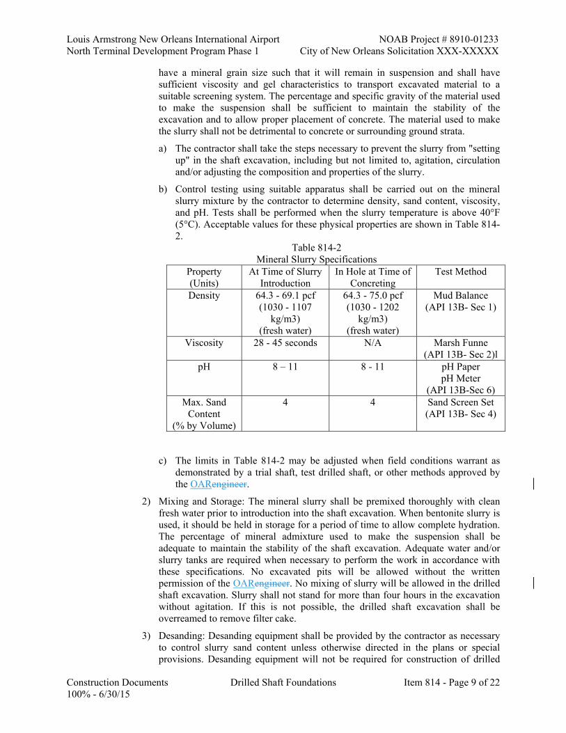
Louis Armstrong New Orleans International Airport NOAB Project # 8910-01233 North Terminal Development Program Phase 1 City of New Orleans Solicitation XXX-XXXXX
Construction Documents Drilled Shaft Foundations Item 814 - Page 9 of 22 100% - 6/30/15
have a mineral grain size such that it will remain in suspension and shall have sufficient viscosity and gel characteristics to transport excavated material to a suitable screening system. The percentage and specific gravity of the material used to make the suspension shall be sufficient to maintain the stability of the excavation and to allow proper placement of concrete. The material used to make the slurry shall not be detrimental to concrete or surrounding ground strata.
a) The contractor shall take the steps necessary to prevent the slurry from "setting up" in the shaft excavation, including but not limited to, agitation, circulation and/or adjusting the composition and properties of the slurry.
b) Control testing using suitable apparatus shall be carried out on the mineral slurry mixture by the contractor to determine density, sand content, viscosity, and pH. Tests shall be performed when the slurry temperature is above 40°F (5°C). Acceptable values for these physical properties are shown in Table 814-2.
Table 814-2 Mineral Slurry Specifications
Property (Units)
At Time of Slurry Introduction
In Hole at Time of Concreting
Test Method
Density 64.3 - 69.1 pcf (1030 - 1107
kg/m3) (fresh water)
64.3 - 75.0 pcf (1030 - 1202
kg/m3) (fresh water)
Mud Balance (API 13B- Sec 1)
Viscosity 28 - 45 seconds N/A Marsh Funne (API 13B- Sec 2)l
pH 8 – 11 8 - 11 pH Paper pH Meter
(API 13B-Sec 6) Max. Sand
Content (% by Volume)
4 4 Sand Screen Set (API 13B- Sec 4)
c) The limits in Table 814-2 may be adjusted when field conditions warrant as demonstrated by a trial shaft, test drilled shaft, or other methods approved by the OARengineer.
2) Mixing and Storage: The mineral slurry shall be premixed thoroughly with clean fresh water prior to introduction into the shaft excavation. When bentonite slurry is used, it should be held in storage for a period of time to allow complete hydration. The percentage of mineral admixture used to make the suspension shall be adequate to maintain the stability of the shaft excavation. Adequate water and/or slurry tanks are required when necessary to perform the work in accordance with these specifications. No excavated pits will be allowed without the written permission of the OARengineer. No mixing of slurry will be allowed in the drilled shaft excavation. Slurry shall not stand for more than four hours in the excavation without agitation. If this is not possible, the drilled shaft excavation shall be overreamed to remove filter cake.
3) Desanding: Desanding equipment shall be provided by the contractor as necessary to control slurry sand content unless otherwise directed in the plans or special provisions. Desanding equipment will not be required for construction of drilled

NOAB Project # 8910-01233 Louis Armstrong New Orleans International Airport City of New Orleans Solicitation XXX-XXXXX North Terminal Development Program Phase 1
Item 814- Page 10 of 22 Drilled Shaft Foundations Construction Documents 100% - 6/30/15
shafts for sign post or lighting mast foundations unless shown in the plans or special provisions.
c. Slurry Testing Frequency: Density, viscosity, sand content, and pH testing shall be performed initially until a consistent working pattern has been established, taking into account the mixing process, and blending of freshly mixed slurry and previously used slurry. Density, viscosity, sand content, and pH value testing shall be performed a minimum of four times during the first eight hours the slurry is in use.
1) Prior to placing concrete in any shaft excavation, the contractor shall ensure that heavily contaminated suspensions, which could impair the free flow of concrete from the tremie pipe, have not accumulated in the bottom of the shaft. Samples of the slurry in the shaft shall be taken from the base of the shaft and at intervals not exceeding 10 feet (3 m) up the shaft, using an approved sampling tool, until two consecutive samples produce acceptable values in accordance with slurry specifications for polymer and mineral slurries.
d. Unacceptable Slurry Test Results: When any slurry samples are tested and found to be unacceptable, the contractor shall take whatever action is necessary to bring the slurry within specification requirements. Concrete shall not be poured until resampling and testing results produce acceptable values.
e. Slurry Test Reports: Reports of all slurry tests required above, signed by an authorized representative of the contractor, shall be furnished to the OARengineer upon completion of each drilled shaft.
f. Slurry Disposal: Disposal of all waste slurry shall be off-site in suitable areas provided by the contractor in accordance with local, state, and federal laws.
g. Required Fluid Level: During construction, the slurry shall be maintained within the excavation at a level not less than 5 feet (1.5 m) above the highest expected piezometric water head within the shaft excavation. The slurry level may be higher if caving or sloughing soils are present above this level.
h. Slurry Performance: If the slurry fails to stabilize the excavation, or if a sudden significant loss of slurry occurs such that the slurry level cannot practically be maintained by adding slurry to the hole, the construction of that foundation shall be continued by the approved contingency method. Construction of new drilled shafts shall be discontinued until the contractor modifies or replaces the existing drilled shaft construction method and obtains written approval from the OARengineer.
i. Blended Mineral-Polymer Slurry: If the contractor elects to use blended mineral-polymer slurry, a detailed report shall be submitted specific to the project, prepared by a qualified slurry consultant. The report shall describe slurry materials, mix proportions, mixing methods and quality control methods. Details of the slurry quality control testing criteria shall also be furnished. A manufacturer's representative shall be present during construction of the trial shaft to provide guidance on the proper proportions, mixing and quality control of the blended mineral-polymer slurry.
1.13 EXCAVATION INSPECTION AND REQUIREMENTS
A. Dimensions and Alignment: The contractor shall provide equipment for checking the dimensions and alignment of each permanent shaft excavation. The dimensions and alignment of the shaft excavation shall be determined by the contractor under the observation and direction of the OARengineer. The alignment and dimensions shall be checked by any of the following methods:

Louis Armstrong New Orleans International Airport NOAB Project # 8910-01233 North Terminal Development Program Phase 1 City of New Orleans Solicitation XXX-XXXXX
Construction Documents Drilled Shaft Foundations Item 814 - Page 11 of 22 100% - 6/30/15
1. Check the dimensions and alignment of dry shaft excavations using reference stakes and a plumb bob.
2. Check the dimensions and alignment of casing when inserted in the excavation.
3. Insert a casing in the shaft excavations temporarily for alignment and dimension checks.
4. Other methods provided by the contractor and approved by the OARengineer. Any casing, rod, or other device used to check dimensions and alignment shall be inserted by the contractor into the excavation to full depth.
B. Depth: The depth of the shaft during drilling shall generally be referenced to appropriate marks on the Kelly bar or by other suitable methods. Final shaft depths shall be measured with a suitable weighted tape or other approved method.
C. Drilled Shaft Cleanliness Requirements: The contractor's cleaning operation shall be adjusted so that no more than 1/2 inch (15 mm) of loose or disturbed material shall be present at the bottom of the shaft just prior to placing concrete for end bearing drilled shafts. No more than 2 inches (50 mm) of loose or disturbed material shall be present for side friction shafts. End bearing shafts shall be assumed unless otherwise noted in the plans, or directed by the OARengineer.
1. Drilled shaft bottom cleanliness will be determined by visual inspection for dry shafts or other methods deemed appropriate by the OARengineer for wet drilled shafts. The device proposed to check for bottom cleanliness shall be approved by the OARengineer prior to use. The bottom of the drilled shaft excavation shall be cleaned, regardless of the method of load distribution, with a cleanout bucket or other appropriate tool. When a cleanout bucket is used, it shall be equipped with a one-way flap gate that prevents spoil in the bucket from re-entering the drilled shaft excavation. End bearing drilled shafts, drilled by the wet construction method, shall require a final bottom cleaning with an air-lift or submersible pump prior to concrete placement. Care shall be taken not to decrease the borehole stability while utilizing the air-lift or submersible pump.
2. In addition, for dry excavations the maximum depth of water covering the bottom of the excavation shall not exceed 3 inches (75 mm) prior to concrete placement.
D. Time of Excavation: No drilled shaft excavation work shall be open for more than 36 hours prior to placing concrete. The excavation time shall start at the beginning of excavation for all construction methods except the permanent casing method, which starts at the time the excavation begins below the permanent casing. If slurry is used, the contractor shall adjust his excavation operations so that the maximum time slurry is in contact with the bottom 5 feet (1.5 m) of the drilled shaft excavation does not exceed 12 hours from drilling to concreting. If these time limits are exceeded, the drilled shaft excavation may require overreaming of the sidewalls and/or overdrilling the excavation prior to performing other operations in the shaft. Costs associated with exceeding these time limits shall be at the contractor's expense.
1.14 REINFORCING STEEL CONSTRUCTION AND POSITIONING
A. Cage Construction and Placement: Fabrication and positioning of reinforcing steel shall conform to Section 806. The contractor shall order and fabricate the steel reinforcing cage after the final drilled shafts depths have been specified. The steel reinforcing cage, consisting of longitudinal and transverse bars, ties, and cage stiffener bars, shall be completely assembled and positioned as a unit immediately after the shaft excavation is inspected and accepted, and prior to concrete placement. The reinforcing cage shall be rigidly braced to retain its configuration during handling and construction. If Crosshole Sonic Logging testing is required, the steel cage shall have attached to it the access tubes as described in Subsection 814.19.

NOAB Project # 8910-01233 Louis Armstrong New Orleans International Airport City of New Orleans Solicitation XXX-XXXXX North Terminal Development Program Phase 1
Item 814- Page 12 of 22 Drilled Shaft Foundations Construction Documents 100% - 6/30/15
B. Cage Extension: If the drilled shaft bottom is extended to an elevation lower than the plan bottom elevation, the reinforcing cage length shall also be extended by the same amount. The reinforcing cage may be extended at the plan bottom elevation by using a lap splice or a mechanical butt splice device to attach additional longitudinal reinforcement in accordance with Section 806. Welding to extend the reinforcing steel shall not be permitted. Tie bars shall be continued for the extra depth, at the same spacing, and the stiffener bars shall be extended to the final depth.
C. Support, Alignment and Tolerance: The reinforcement steel in the drilled shaft shall be carefully positioned and securely fastened and supported so that the reinforcing steel remains within the allowable tolerances given in Subsection 814.17(c).
D. Spacers: Concrete wheels, with a minimum width of 1 inch (25 mm), or other non-corrosive rolling spacing devices, approved by the OARengineer, shall be placed at the top and bottom of the steel reinforcement cage and at sufficient intervals along the shaft to insure concentric spacing for the entire length of the steel reinforcement cage. Block type spacers will not be allowed. For longitudinal reinforcement less than 1 inch (25 mm) diameter, spacing devices shall be placed at intervals not exceeding 5 feet (1.5 m) along the shaft. For longitudinal reinforcement, 1 inch (25 mm) diameter or larger, spacing devices shall be placed at intervals not exceeding 10 feet (3 m) along the shaft. A minimum of one spacer per 3 feet (1 m) of circumference of cage with a minimum of three at each level shall be used. Additional spacers may be required if deemed necessary by the OARengineer. Concrete or other approved non-corrosive spacers, approved by the OARengineer, shall be provided at the bottom of the drilled shaft reinforcing cage to insure that the specified distance between the bottom of the cage and the bottom of the shaft is maintained. The bottom spacers shall be constructed of approved material equal in quality and durability to the concrete specified for the shaft. Bottom spacers will not be required if the steel reinforcing cage is supported at the top of the hole.
E. Reinforcement Cage Elevation: The elevation of the top of the steel reinforcement cage shall be checked before and after the concrete is placed. If the reinforcement cage is not maintained within the specified tolerances, corrections shall be made by the contractor as directed by the OARengineer. No additional shafts shall be constructed until the contractor has modified his reinforcement cage support in a manner satisfactory to the engineerOAR.
F. Column Steel: The minimum length of steel required for lap with column steel shall be maintained. Dowel bars in the top of the shaft shall be placed and tied prior to starting concrete pour unless approved otherwise by the engineerOAR.
1.15 CONCRETE PLACEMENT METHOD
A. The contractor may use any of the placement methods described herein. Details pertaining to compliance with this specification shall be furnished in the contractor's drilled shaft installation plan.
B. Free Fall Method:
1. Requirements: The free fall placement of concrete shall only be permitted in dry vertical shafts where the clear opening (inside the reinforcing cage) is not less than 24 inches (600 mm) in diameter. The height of free fall placement shall not exceed 75 feet (23 m) measured from the bottom of the hopper or drop chute to the point of deposition. Concrete placed by free fall shall fall directly to the placement location without contacting either the reinforcing cage or the shaft sidewall.
a. A hopper shall be used at the top of the shaft to center and direct the free fall placement. The contractor shall reduce the rate of concrete placement or reduce the
Louis Armstrong New Orleans International Airport NOAB Project # 8910-01233 North Terminal Development Program Phase 1 City of New Orleans Solicitation XXX-XXXXX
Construction Documents Drilled Shaft Foundations Item 814 - Page 13 of 22 100% - 6/30/15
height of free fall as directed by the engineer OAR if the concrete strikes the reinforcing cage or sidewall.
2. Disqualification of Free Fall Method: If in the opinion of the engineerOAR, concrete placement cannot be satisfactorily accomplished by the free fall method, the contractor shall change to either tremie or pumping methods to accomplish the concrete placement.
C. Tremie and Pumped Concrete Placement Methods:
1. Tremie: Tremies shall consist of a tube of sufficient length, weight, and diameter to discharge concrete at the shaft base elevation. Inside and outside surfaces of the tremie shall be clean and smooth to permit both flow of concrete and unimpeded withdrawal during concreting. The wall thickness of the tremie shall be adequate to prevent crimping or sharp bends that restrict concrete placement. The tremie's inside diameter shall be at least 6 times the maximum aggregate size used in the concrete mix but shall not be less than 10 inches (250 mm). Tremies shall be clearly marked at one foot increments. Tremies used for concrete placement in dry excavations shall consist of: a tube of solid construction; a tube constructed of sections which can be added and removed; or a tube of other approved design. Aluminum tremies will not be allowed. Tremies used for concrete placement in wet excavations shall be constructed as follows:
a. The tremie pipe is watertight and discharges concrete readily
b. The discharge end of the tremie shall prevent intrusion of slurry
c. The discharge end of the tremie shall be constructed to permit the free radial flow of concrete during placement operations
d. The tremie shall have sufficient weight that it will rest on the shaft bottom before the start of concrete placement.
2. Pumped Concrete: The contractor may use concrete pumps approved by the engineer OAR in lieu of tremies to place concrete for drilled shafts. Concrete pumps shall have sufficient capacity to place the concrete within the time limit specified. The pump lines shall have a minimum 4 inch (100 mm) diameter and shall be constructed so that all sections have watertight joints.
3. Concrete Placement: Tremied or pumped concrete may be used for concrete placement in either wet or dry excavations.
a. Dry Excavations: Concrete may be passed through a hopper at the top of the tremie or through side openings as the tremie is retrieved during concrete placement. The tremie or pump line shall be supported so that the free fall of the concrete is less than 5 feet (1.5 m) at all times. If the free falling concrete causes the shaft sides to cave or slough, the contractor shall control the movement of concrete by reducing the height of free fall of the concrete and/or reducing the rate of flow of concrete into the excavation.
b. Wet Excavations: When a tremie is used for concrete placement, bottom plates or plugs will be required to ensure that there is a minimum of concrete contamination. When a bottom seal is used, the tremie shall be sealed prior to placing the tremie in the wet excavation. The tremie pipe shall be placed on the bottom of the excavation and charged with concrete prior to lifting the tremie to release the bottom seal. The tremie should only be raised enough to release the bottom seal and start the flow of concrete, approximately 1 foot (300 mm). When a plug or pig is placed at the top of the tremie it shall be inserted after the tremie is placed in the wet excavation and before the tremie is charged with concrete. The bottom of the tremie shall be placed slightly off the bottom of the excavation to allow the plug or pig to pass out of the tremie.

NOAB Project # 8910-01233 Louis Armstrong New Orleans International Airport City of New Orleans Solicitation XXX-XXXXX North Terminal Development Program Phase 1
Item 814- Page 14 of 22 Drilled Shaft Foundations Construction Documents 100% - 6/30/15
1) When a concrete pump with rigid steel pump line is used for concrete placement, a plug or pig is to be placed in the rigid pump line to minimize concrete contamination. The plug or pig is to be placed near the top of the rigid line after the rigid line has been placed in the wet excavation and before the rigid line is connected to the surface line from the pump. The rigid pump line shall be equipped with a vent to prevent air pressure build up in the surface line at the beginning of concrete pumping operations. The air vent shall be closed when the concrete in the surface line reaches the pig in the rigid line.
2) The discharge end of the tremie or rigid pump line shall be immersed at least 5 feet (1.5 m) into the concrete at all times and shall not be removed after starting the flow of concrete. The flow of the concrete shall be continuous. The concrete in the tremie or pump line shall be maintained with a positive head at all times to prevent water or slurry intrusion into the shaft concrete. If at any time during the concrete pour, the tremie or pump line discharge end is removed from the fluid concrete column and discharges concrete above the rising concrete level, the shaft shall be considered defective. The contractor shall have the option, at the time the concrete pour is interrupted, to recharge the tremie and continue the pour at his own risk or to remove the reinforcing cage and concrete, complete any necessary sidewall overreaming as directed by the engineerOAR, and repour the shaft.
1.16 CONCRETE PLACEMENT REQUIREMENTS
A. Concrete shall be placed in accordance with Section 805 and the requirements herein.
B. Concrete Placement Responsibility: The drilled shaft contractor shall be responsible for placement of the concrete in the drilled shaft. Prior to concrete placement, the drilled shaft contractor shall make all necessary arrangements to assure the uninterrupted delivery of concrete so that all drilled shaft foundations shall be constructed without cold joints.
C. Concrete Placement Contingencies: The contractor shall have readily available all equipment and materials necessary for mitigating situations that may occur during drilled shaft concrete placement such as unforeseen stoppage of work, drop in concrete pressure, delays in concrete placement, etc. Contingency methods shall be submitted with the drilled shaft installation plan for approval.
D. Concrete Placement Log: When concrete placement is under slurry, or as directed by the engineerOAR, a concrete placement log will be maintained to document the method of concrete placement. The contractor shall assist the engineer OAR in determining the actual volume of concrete placed, elevation of top of concrete in the shaft, and elevation of tremie or pump line discharge end.
E. Concrete Placement Time Limitations: Concrete shall be placed as soon as possible after the reinforcing steel placement and shall be continuous from the bottom to the top elevation of the shaft. Concrete placement shall continue after the shaft excavation is full, until good quality concrete is evident at the top of the drilled shaft. Unless approved otherwise by the engineerOAR, the elapsed time from beginning to completion of concrete placement in the drilled shaft shall not exceed two hours for drilled shafts 5 feet (1.5 m) diameter or less. The minimum concrete placement rate for drilled shafts larger than 5 feet (1.5 m) diameter shall be 30 cubic yards (23 cu m) per hour.
1. The engineer OAR may allow an extension of the concrete placement time if the contractor adequately demonstrates by trial mix and slump loss tests that the slump of the concrete

Louis Armstrong New Orleans International Airport NOAB Project # 8910-01233 North Terminal Development Program Phase 1 City of New Orleans Solicitation XXX-XXXXX
Construction Documents Drilled Shaft Foundations Item 814 - Page 15 of 22 100% - 6/30/15
will be no less than 4 inches (100 mm) during the entire time of concrete placement during the longer placement time.
2. These tests shall be conducted by a DOTD certified concrete technician in the presence of the engineerOAR. The slump loss tests shall be performed at intervals not to exceed 30 minutes and shall be made from a trial mix proportioned from the approved concrete mix design. The temperature of the trial mix shall be kept at a level representative of construction site conditions. A slump loss versus time curve shall be furnished to the engineer OAR prior to concreting production shafts.
F. Top of Drilled Shaft: Concrete placed under slurry shall not be vibrated, unless directed by the engineerOAR, in the top 5 feet (1.5 m) of the drilled shaft after the slurry, contaminated concrete, and surface casing have been removed. After concrete placement is completed, the top surface shall be cured and construction joint areas shall be treated as specified in Section 805.
1. Concrete placement in wet excavations shall be overpoured until all slurry and contaminated concrete has been removed. Temporary sump holes used for slurry recovery and concrete overpour shall not exceed 5 feet (1.5 m) in depth. The temporary sump holes shall be cleaned out and backfilled to the satisfaction of the engineerOAR.
1.17 DRILLED SHAFT CONSTRUCTION TOLERANCES
A. The following construction tolerances shall apply for drilled shafts unless otherwise stated in the contract documents. During drilling or excavation of the drilled shaft, the contractor shall make frequent checks on the plumbness, alignment, and dimensions of the shaft. Drilled shafts constructed out of tolerance are unacceptable and shall be considered defective. These out of tolerance shafts shall be backfilled, in an approved manner, when directed by the engineer OAR until the redesign is completed and approved.
B. Horizontal Location: When drilled shafts support a single column, the center of the top of the drilled shaft shall vary no more than 3 inches (75 mm) in the horizontal plane of the position indicated in the plans. The top of all other drilled shafts shall be constructed so that the center is within the following tolerances of the position indicated in the plans unless otherwise directed by the engineerOAR.
Table 814-3
Drilled Shaft Horizontal Tolerance Drilled Shaft Diameter, D Horizontal Tolerance
D ≤ 2 feet D ≤ 600 mm 3 inches 75 mm 2 < D ≤ 3 feet 600 < D ≤ 900 mm 3 1/2 inches 90 mm 3 < D ≤ 4 feet 900 < D ≤ 1200 mm 4 inches 100 mm
D > 4 feet D > 1200 mm 6 inches 150 mm
C. Excavation Vertical Alignment: The vertical alignment of the shaft excavation shall be within 1.5 percent of plumb.
D. Reinforcing Steel Cage: After all the concrete is placed, the top of the reinforcing steel cage shall be no more than 4 inches (100 mm) above and no more than 3 inches (75 mm) below plan position, and shall be at least 1 inch (25 mm) below the top of the shaft. When the shaft reinforcing cage is to be tied directly to the column steel the shaft reinforcing cage shall be
NOAB Project # 8910-01233 Louis Armstrong New Orleans International Airport City of New Orleans Solicitation XXX-XXXXX North Terminal Development Program Phase 1
Item 814- Page 16 of 22 Drilled Shaft Foundations Construction Documents 100% - 6/30/15
within 1/2 inch (15 mm) of the plan location. On all other shafts, the reinforcing cage shall be concentric with the shaft within a tolerance of 1 1/2 inches (40 mm).
E. Top Elevation of Shafts: The top elevation of the drilled shaft concrete shall be within 2 inches (50 mm) of the top of shaft elevation shown in the plans.
F. Drilled Shaft Diameter: The minimum diameter of the drilled shaft shall be the diameter shown in the plans.
G. Excavation Equipment And Methods: Excavation equipment and methods shall be designed so that the completed shaft excavation will have a flat bottom and shall be normal to the axis of the shaft within 3/4 inch per foot (60 mm/m) of drilled shaft diameter. The cutting edges of excavation equipment shall be normal to the vertical axis of the equipment within a tolerance of plus or minus 3/8 inch per foot (30 mm/m) of drilled shaft diameter.
1.18 DEFECTIVE DRILLED SHAFTS
A. The contractor shall be responsible for correcting defective drilled shafts, including redesign, to the satisfaction of the engineerOAR. All corrective proposals to restore or replace defective drilled shafts shall be reviewed for approval by the DepartmentOAR. Corrective actions may consist of, but are not limited to: removing the shaft concrete and extending the shaft deeper, providing straddle shafts, or providing a replacement shaft. No compensation will be paid for abandoned casings, concrete, etc. that remain in place. When the drilled shaft is found defective core sampling and additional nondestructive testing shall be at no direct pay. If the shaft is accepted, only core sampling and grouting, will be paid for by the DepartmentOwner. A unit price for coring will be established prior to the coring operations.
1.19 NONDESTRUCTIVE TESTING OF DRILLED SHAFTS
A. The nondestructive testing (NDT) method termed Crosshole Sonic Logging (CSL) shall be used to check the integrity of newly-placed concrete drilled shafts. The CSL testing system shall measure the time it takes for an ultrasonic pulse to travel from a signal source in one access tube to a receiver in another access tube.
1. The CSL test shall be used on all production shafts, trial shafts, and test drilled shafts when any of the following conditions occur:
a. A drilled shaft is constructed with the placement of concrete through slurry.
b. A full-length casing is used to prevent water from entering the shaft.
c. Determined to be necessary by the engineerOAR.
2. The installation of access tubes and dewatering/grouting the tubes after the CSL testing has been performed shall be at no direct pay.
a. NDT Consultant: The NDT consultant shall be an experienced independent test organization approved by the engineer OAR prior to testing. All CSL testing and analyses shall be performed under the supervision of a registered professional engineer in the State of Louisiana. The NDT consultant shall have a minimum of three years experience in field testing and analyses of CSL test results.
b. Testing Schedule: The CSL testing for all drilled shafts shall not be conducted until 24 hours after the placement of all concrete in a shaft. After placement of concrete, all CSL tests for production drilled shafts must be completed within 48 hours for PVC access tubes and 20 calendar days for steel access tubes. CSL tests for trial shafts and test drilled shafts must be completed within 48 hours after placement of concrete.
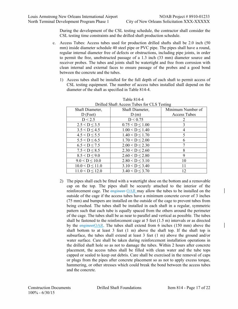
Louis Armstrong New Orleans International Airport NOAB Project # 8910-01233 North Terminal Development Program Phase 1 City of New Orleans Solicitation XXX-XXXXX
Construction Documents Drilled Shaft Foundations Item 814 - Page 17 of 22 100% - 6/30/15
During the development of the CSL testing schedule, the contractor shall consider the CSL testing time constraints and the drilled shaft production schedule.
c. Access Tubes: Access tubes used for production drilled shafts shall be 2.0 inch (50 mm) inside diameter schedule 40 steel pipe or PVC pipe. The pipes shall have a round, regular internal diameter free of defects or obstructions, including pipe joints, in order to permit the free, unobstructed passage of a 1.3 inch (33 mm) diameter source and receiver probes. The tubes and joints shall be watertight and free from corrosion with clean internal and external faces to ensure passage of the probes and a good bond between the concrete and the tubes.
1) Access tubes shall be installed for the full depth of each shaft to permit access of CSL testing equipment. The number of access tubes installed shall depend on the diameter of the shaft as specified in Table 814-4.
Table 814-4
Drilled Shaft Access Tubes for CLS Testing Shaft Diameter,
D (Feet) Shaft Diameter,
D (m) Minimum Number of
Access Tubes D < 2.5 D < 0.75 2
2.5 < D ≤ 3.5 0.75 < D ≤ 1.00 3 3.5 < D ≤ 4.5 1.00 < D ≤ 1.40 4 4.5 < D ≤ 5.5 1.40 < D ≤ 1.70 5 5.5 < D ≤ 6.5 1.70 < D ≤ 2.00 6 6.5 < D ≤ 7.5 2.00 < D ≤ 2.30 7 7.5 < D ≤ 8.5 2.30 < D ≤ 2.60 8 8.5 < D ≤ 9.0 2.60 < D ≤ 2.80 9
9.0 < D ≤ 10.0 2.80 < D ≤ 3.10 10 10.0 < D ≤ 11.0 3.10 < D ≤ 3.40 11 11.0 < D ≤ 12.0 3.40 < D ≤ 3.70 12
2) The pipes shall each be fitted with a watertight shoe on the bottom and a removable
cap on the top. The pipes shall be securely attached to the interior of the reinforcement cage. The engineer OAR may allow the tubes to be installed on the outside of the cage if the access tubes have a minimum concrete cover of 3 inches (75 mm) and bumpers are installed on the outside of the cage to prevent tubes from being crushed. The tubes shall be installed in each shaft in a regular, symmetric pattern such that each tube is equally spaced from the others around the perimeter of the cage. The tubes shall be as near to parallel and vertical as possible. The tubes shall be fastened to the reinforcement cage at 5 feet (1.5 m) intervals or as directed by the engineerOAR. The tubes shall extend from 6 inches (150 mm) above the shaft bottom to at least 3 feet (1 m) above the shaft top. If the shaft top is subsurface, the tubes shall extend at least 3 feet (1 m) above the ground and/or water surface. Care shall be taken during reinforcement installation operations in the drilled shaft hole so as not to damage the tubes. Within 2 hours after concrete placement, the access tubes shall be filled with clean water and the tube tops capped or sealed to keep out debris. Care shall be exercised in the removal of caps or plugs from the pipes after concrete placement so as not to apply excess torque, hammering, or other stresses which could break the bond between the access tubes and the concrete.

NOAB Project # 8910-01233 Louis Armstrong New Orleans International Airport City of New Orleans Solicitation XXX-XXXXX North Terminal Development Program Phase 1
Item 814- Page 18 of 22 Drilled Shaft Foundations Construction Documents 100% - 6/30/15
d. CSL Test Equipment: The CSL test equipment shall be capable of performing the following functions:
1) Displaying individual CSL records, recording CSL data, and analyzing receiver responses.
2) Printing of CSL logs.
3) Testing in 2 inch (50 mm) I.D. access tubes.
4) Generating an ultrasonic voltage pulse to excite the source with a synchronized triggering system to start the recording system.
5) Measuring and recording the depths of CSL probes at the time signals are recorded.
6) Filtering/amplifying signals.
e. CSL Logging Procedures: The shaft identification, shaft bottom and top elevations, length, and date of concrete placement shall be provided to the NDT consultant prior to performing CSL testing. As a minimum, all perimeter tube pairs and major diagonal tube pairs shall be tested. If a possible defect is found, CSL testing shall be conducted between additional pairs of tubes as determined by the NDT consultant.
1) The CSL tests shall be carried out with the source and receiver probes in the same horizontal plane unless test results indicate potential defects in which case the questionable zone may be further evaluated with angled tests consisting of the source and receiver vertically offset in the access tubes. CSL measurements shall be made at depth intervals of 2 inches (50 mm). The probes shall be pulled simultaneously, starting from the bottom of the tubes, over a depth measuring device. Any slack shall be removed from the cables prior to pulling to provide for accurate depth measurements.
f. CSL Testing Results: A preliminary report shall be provided to the Pavement and Geotechnical Services Section within 72 hours of CSL testing. Two copies of the final CSL testing report shall be furnished to the engineer OAR within 10 working days of testing. The test results shall include CSL logs with analyses of the initial pulse arrival time versus depth and pulse energy/amplitude versus depth. A CSL log shall be presented for each tube pair tested with any defect zones indicated on the logs and discussed in the test report as appropriate. A summary of the CSL test results shall be included in the report. The CSL test summary shall include the drilled shaft identification, test date, shaft age at time of CSL testing (days from concrete placement to CSL testing), drilled shaft diameter, number of CSL tubes tested, test length, average compression velocity, and a description of anomalies detected. Each CSL anomaly description shall include CSL tube number, depth below top of concrete, percent concrete wave speed reduction, and recommended concrete condition rating.
g. Evaluation of CSL Testing: The Geotechnical EngineerOAR will evaluate the CSL test results and determine whether the drilled shaft construction is acceptable. The contractor shall allow three working days for the evaluation to be conducted after the receipt of the testing report and logs. In uniform good quality concrete, the CSL test will produce records with good signal amplitude and energy. Longer travel times or loss of signal and lower amplitude/energy signals indicate the presence of irregularities such as poor quality concrete, voids, honeycomb and soil intrusions. Any defects indicated by the testing shall be reported to the Geotechnical EngineerOAR and further tests shall be conducted as required to evaluate the extent of such defects. Additional nondestructive testing to determine extent of defects or to determine if tube debonding
Louis Armstrong New Orleans International Airport NOAB Project # 8910-01233 North Terminal Development Program Phase 1 City of New Orleans Solicitation XXX-XXXXX
Construction Documents Drilled Shaft Foundations Item 814 - Page 19 of 22 100% - 6/30/15
has occurred shall be at no additional pay. If the Geotechnical EngineerOAR determines that the drilled shaft is unacceptable based on CSL or other nondestructive testing, the shaft shall be considered defective.
h. Abandoning CSL Access Tubes: After the CSL testing has been completed and the engineer OAR has given approval to continue construction, the contractor shall dewater and grout the access tubes in the drilled shaft. The grout and grouting method shall be approved by the engineerOAR.
1.20 CORE DRILLING OF DRILLED SHAFT CONCRETE
A. Production drilled shafts or test drilled shafts that are determined to be unacceptable by the CSL tests, or drilled shafts that, in the opinion of the engineerOAR, are suspected to have defects, may be cored to determine the quality of the concrete. Number, depth, and location of cores shall be as determined by the engineerOAR. Core samples shall be at least 2 inches (50 mm) in diameter. The methods and equipment used to core the drilled shaft and grout the cored hole shall be approved by the engineer OAR prior to commencing coring operations.
B. Concrete Core Log: An accurate log of cores shall be kept and the cores shall be placed in a crate and properly marked showing the shaft depth at each interval of core recovery. The OARengineer shall direct the contractor where to transport the cores along with a copy of the coring log.
C. Concrete Core Sample Evaluation: Construction shall not proceed above a drilled shaft until the quality of the concrete in the shaft, as represented by the core samples, is determined to be acceptable and notification to continue construction is given by the OARengineer. If the quality of the concrete in a drilled shaft is determined to be unacceptable, then the drilled shaft shall be considered defective.
1.21 TRIAL SHAFTS
A. When shown in the plans or when ordered by the OARengineer in writing, trial shafts will be required. The construction of trial shafts will be used to determine if the methods and equipment used by the contractor are sufficient to produce a shaft excavation meeting the requirements of the plans and specifications. Trial shafts shall be constructed and approved prior to constructing production shafts. Trial shafts will be evaluated based on field observation and will not be finalized prior to receiving CSL results. The contractor will be evaluated during trial shaft excavations on his ability to:
1. Control dimensions and alignment of excavations within tolerances.
2. Seal the casing into impervious materials.
3. Control the size of the excavation under caving conditions by the use of slurry or by other means.
4. Properly clean the completed shaft excavation.
5. Construct excavations in open water areas.
6. Determine the elevation of ground water.
7. Satisfactorily place concrete meeting the specifications within the prescribed time frame.
8. Properly pick up and position the reinforcing cage.
9. Satisfactorily execute any other necessary construction operations.

NOAB Project # 8910-01233 Louis Armstrong New Orleans International Airport City of New Orleans Solicitation XXX-XXXXX North Terminal Development Program Phase 1
Item 814- Page 20 of 22 Drilled Shaft Foundations Construction Documents 100% - 6/30/15
B. The contractor shall revise his methods and equipment as necessary at any time during the construction of the trial shaft when he is unable to satisfactorily carry out any of the necessary operations described above.
1. Location, Size, and Depth: The trial shaft shall be drilled at the location shown in the plans, or as directed by the OARengineer. If the diameter of the trial shaft is not shown in the plans, the trial shaft diameter shall be the diameter of the largest production drilled shafts required by the plans. If the depth of the trial shaft is not shown in the plans, the trail shaft depth shall be the depth of the deepest production drilled shaft, or as directed by the OARengineer.
2. Construction Requirements: The trial shaft shall be constructed with a reinforcing cage containing the same reinforcing steel configuration as shown in the plans for the production shafts. The trial shaft shall be filled with concrete in the same manner that production reinforced drilled shafts will be constructed, unless directed otherwise by the OARengineer. The concreted trial shaft shall be left in place except that the top of the shaft shall be removed to a depth of 2 feet (600 mm) below the final ground line. This also shall apply to shafts constructed in water.
3. Trial Shaft Evaluation: When the contractor fails to demonstrate, to the OARengineer, the adequacy of his methods or equipment, additional trial shafts shall be provided at no cost to the DepartmentOwner. No test drilled shafts or production shafts shall be constructed until the trial shaft has been evaluated. This evaluation will include review of excavation methods, field construction procedures, and all CSL test results.
1.22 MEASUREMENT
A. Drilled Shafts: Drilled shafts shall be measured from the approved tip elevation by the linear foot (lin m).
B. Trial Shafts: Trial shafts will be measured by the linear foot (lin m) installed.
C. Permanent Casing: Permanent casing shall be measured by the linear foot (lin m).
D. Crosshole Sonic Logging: Crosshole Sonic Logging shall be measured for each drilled shaft tested.
1.23 PAYMENT
A. Drilled Shafts: Payment for drilled shafts will be made by the linear foot (lin m) and will include all necessary materials and equipment required for excavating, pumping, furnishing and placing casings, furnishing and placing concrete and reinforcement, removing casings, casings left in place, slurry, slurry testing equipment and performing slurry testing, disposing of slurry, furnishing and installing access tubes for nondestructive testing, any delays due to nondestructive testing schedule, and disposing of excess excavated material. No payment will be made for concrete required to fill oversize casings or excavation.
B. Acceptance and payment for concrete drill shafts will be on a lot basis at the contract unit price per linear foot (lin m), adjusted in accordance with the following provisions. A lot will be considered as a continuous identifiable pour that is completed in one day. Multiple shafts poured on the same day but in a non-continuous pouring operation will require separate lots for each identifiable pour. Six cylinders per lot will be tested for compressive strength and in the event of sudden cessation of operation a minimum of three cylinders will constitute a lot. Acceptance and payment for each lot will be made in accordance with Table 901-5 and Note 1. Authorized overruns shall be paid as follows:

Louis Armstrong New Orleans International Airport NOAB Project # 8910-01233 North Terminal Development Program Phase 1 City of New Orleans Solicitation XXX-XXXXX
Construction Documents Drilled Shaft Foundations Item 814 - Page 21 of 22 100% - 6/30/15
1. Payment for shaft lengths in excess of plan length, up to and including 16 feet (5 m) will be made at the contract unit price per linear foot (lin m). When reinforcing splices are required due to increases in shaft length up to and including 16 feet (5 m) the additional deformed reinforcing steel required for splices will be paid for at the contract unit price. No other compensation will be made for increases in shaft lengths up to 16 feet (5 m).
2. Payment for that portion of shaft lengths greater than 16 feet (5 m) will be made in accordance with Subsection 109.04.
C. Trial Shafts: Payment for trial shafts will be made at the contract unit price per linear foot (lin m) and shall include the cost of CSL Testing.Payment for trial shafts required by the OAR engineer but not specified by the plans, except when required for acceptance of polymer slurries, will be made in accordance with Subsection 109.04.
D. Permanent Casing: Payment for permanent casing shall be paid at the contract unit price per linear foot (lin m).
E. Crosshole Sonic Logging: Payment for Crosshole Sonic Logging testing shall be made at the contract unit price per each drilled shaft tested. Payment shall be for all labor, materials, equipment, and incidentals necessary to perform the required test and furnish the CSL report.
F. Payment will be made under:
Unit Price Pay items are listed in Section 01 22 00, Unit Price Pay Items. For Work not otherwise identified as being paid on Lump Sum basis, where no pay item is listed in Section 01 22 00, such work is considered subsidiary to other work, or incidental and will not be measured separately for payment.
END OF SECTION 814

NOAB Project # 8910-01233 Louis Armstrong New Orleans International Airport City of New Orleans Solicitation XXX-XXXXX North Terminal Development Program Phase 1
Item 814- Page 22 of 22 Drilled Shaft Foundations Construction Documents 100% - 6/30/15
THIS PAGE INTENTIONALLY LEFT BLANK

Louis Armstrong New Orleans International Airport NOAB Project # 8910-01233 North Terminal Development Program Phase 1 City of New Orleans Solicitation XXX-XXXXX
Construction Documents Welding Item 815 - Page 1 of 4 100% - 6/30/15
SECTION 815 WELDING
1.1 DESCRIPTION
A. Welding of structural steel, steel pipe and tubular members, reinforcing steel and aluminum alloys (including qualification of procedures, welders and welding operators, destructive and nondestructive testing, etc.) shall comply with these specifications.
1.2 QUALIFICATION OF PROCEDURES, WELDERS AND WELDING OPERATORS.
A. General:
1. The Construction Section shall be the qualifying agency.
2. Qualifying tests may be made at locations selected by the contractor and approved by the DepartmentOAR. Advance notice of not less than 1 week shall be given to the Construction Section so that the Department OAR can arrange for the presence of the inspector.
3. Seven copies of the required reports shall be furnished to the Construction Section.
4. Each welder and welding operator's work shall be identified with a steel stencil.
5. The social security number and 1 inch by 1 inch (25 mm by 25 mm) passport type picture of each qualifying welder and welding operator shall be furnished. The social security number of the qualified welder and welding operator shall be recorded on the required reports. The qualified welder and welding operator shall have the identification card in their possession when working.
6. All costs incidental to welding qualifications shall be the responsibility of the contractor.
B. Structural Steel, Steel Pipe and Tubular Members:
1. Structural Steel: Welding procedures, welders and welding operators shall be qualified in accordance with the latest edition of ANSI/AASHTO/AWS D1.5 (D1.5M) Bridge Welding Code.
2. Steel Pipe and Tubular Members: Welding procedures, welders and welding operators shall be qualified in accordance with the latest edition of ANSI/AWS D1.1 (D1.1M) Structural Welding Code-Steel.
C. Reinforcing Steel: Welding qualification for reinforcing steel shall comply with the latest edition of AWS D 1.4Structural Welding Code-Reinforcing Steel.
D. Aluminum: Welding qualification for aluminum alloys shall comply with the latest edition of ANSI/AWS D 1.2 Structural Welding Code-Aluminum.
E. Electrodes:
1. Structural Steel: Electrodes shall be qualified and certified in accordance with the latest edition of ANSI/AASHTO/AWS D1.5 (D1.5- M) Bridge Welding Code.
2. Steel Pipe and Tubular Members: Electrodes shall be qualified and certified in accordance with the latest edition of ANSI/AWS D1.1(D1.1 M) Structural Welding Code-Steel.
3. Aluminum: Electrodes shall be qualified and certified in accordance with the latest edition of ANSI/AWS D1.2(D1.2M), Structural Welding Code-Aluminum.
1.3 WELDING
NOAB Project # 8910-01233 Louis Armstrong New Orleans International Airport City of New Orleans Solicitation XXX-XXXXX North Terminal Development Program Phase 1
Item 815- Page 2 of 4 Welding Construction Documents 100% - 6/30/15
A. Size, type and length of welds shall be shown on the plans. The use of electroslag and electrogas welding processes will not be permitted.
B. Structural Steel, Steel Pipe and Tubular Members:
1. Structural Steel: Welding of structural steel shall comply with the latest edition of ANSI/AASHTO/AWS D1.5 (D1.5M) Bridge Welding Code. All minimum preheat and interpass temperatures in this code that are less than 125°F (50°C) are amended to be a minimum of 125°F (50°C).
2. Steel Pipe and Tubular Members: Welding of steel pipe and tubular members shall comply with the latest edition of ANSI/AWS D1.1(D1.1M) Structural Welding Code-Steel. All minimum preheat and interpass temperatures in this code that are less than 125°F (50°C) are amended to be a minimum of 125°F (50°C).
C. Reinforcing Steel: Welding of reinforcing steel shall comply with the latest edition of AWS D1.4 Structural Welding Code-Reinforcing Steel.
D. Aluminum: Welding of aluminum alloys shall comply with the latest edition of ANSI/AWS D1.2(D1.2M) Structural Welding Code-Aluminum.
1.4 NONDESTRUCTIVE TESTING
A. Structural Steel, Steel Pipe and Tubular Members:
1. Structural Steel: Non-destructive testing shall comply with the ANSI/AASHTO/AWS latest edition of D1.5 (D1.5M) Bridge Welding Code except that the ends of all groove welds on main members shall be tested with the dye penetrant inspection method.
2. Steel Pipe and Tubular Members: Non-destructive testing shall comply with the latest edition of ANSI/AWS D1.1(D1.1M) Structural Welding Code-Steel.
3. Edge Block: Edge blocks shall be used when radiographing butt welds greater than 1/2 inch (13 mm) in thickness. The edge blocks shall have a length sufficient to extend beyond each side of the weld centerline for a minimum distance equal to the weld thickness, but no less than 2 inches (50mm), and shall have a thickness equal to or greater than the thickness of the weld. The minimum width of the edge blocks shall be equal to half the weld thickness, but not less than 1 inch (25 mm). The edge blocks shall be centered on the weld with a snug fit against the plate being radiographed, allowing no more than a 1/16 inch (2 mm) gap. Edge blocks shall be made of radiographically clean steel and the surface shall have an ANSI 125 μinch (3.2 μm) or smoother finish.
B. Reinforcing Steel: Non-destructive testing shall comply with thelatest edition of AWS D1.4Structural Welding Code-Reinforcing Steel.
C. Aluminum: Non-destructive testing shall comply with the latest edition of ANSI/AWS D1.2 (D1.2M) Structural Welding Code-Aluminum. For sign structures, the dye penetrant method shall be used on butt welds in columns and main chord members, including associated flanges, gussets or main load carrying brackets or members also on fillet welds connecting flanges to main truss chord members.
D. Personnel Qualification: Persons performing ultrasonic testing shall be qualified by tests administered by the Construction Section, unless otherwise approved.
1.5 MEASUREMENT AND PAYMENT
A. There will be no direct payment for radiographic inspection, magnetic particle inspection, dye penetrant inspection or other tests as specified. There will be no measurement or payment made

Louis Armstrong New Orleans International Airport NOAB Project # 8910-01233 North Terminal Development Program Phase 1 City of New Orleans Solicitation XXX-XXXXX
Construction Documents Welding Item 815 - Page 3 of 4 100% - 6/30/15
for weld metal deposited;however, there will be no deduction made for removal of metal to be welded due to edge preparation.
END OF SECTION 815

NOAB Project # 8910-01233 Louis Armstrong New Orleans International Airport City of New Orleans Solicitation XXX-XXXXX North Terminal Development Program Phase 1
Item 815- Page 4 of 4 Welding Construction Documents 100% - 6/30/15
THIS PAGE INTENTIONALLY LEFT BLANK

Louis Armstrong New Orleans International Airport NOAB Project # 8910-01233 North Terminal Development Program Phase 1 City of New Orleans Solicitation XXX-XXXXX
Construction Documents Portland Cement Concrete Item 901 - Page 1 of 18 100% - 6/30/15
SECTION 901 PORTLAND CEMENT CONCRETE
1.1 GENERAL
A. This section specifies requirements for portland cement concrete, including methods and equipment for handling and storing materials, and mixing and transporting concrete to the site.
B. Structural concrete is designated by class and pavement concrete by type.
C. No concrete shall be mixed, placed or finished when natural light is insufficient, unless an approved artificial lighting system is provided. No concrete shall be placed on a frozen subgrade nor shall frozen aggregates be used in concrete.
D. Portland cement concrete shall conform to the requirements of Table 901-3, Master Proportion Table for Portland Cement Concrete. It shall be a mixture of portland cement, portland-pozzolan cement, or portland blastfurnace slag cement, fine aggregate, coarse aggregate, water and, when specified or allowed, approved admixtures. Fly ash or ground granulated blast furnace slag will be permitted as a partial replacement for Portland cement in accordance with Subsection 901.08.
E. Portland cement concrete shall require a Department LADTOD approved mix design, be produced from a Department LADTOD certified plant and be transported in Department LADTOD certified trucks. The design, control and transportation of concrete mixtures in accordance with these specifications shall be the responsibility of the contractor.
F. Sufficient plant capacity and transporting apparatus to ensure delivery at the required rate shall be provided. Rate of concrete delivery during concreting operations shall provide for proper handling, placing and finishing of concrete and maintaining a workable surface.
G. Methods of delivery and handling concrete shall facilitate placing with a minimum of rehandling and without damage to the structure or concrete.
H. Approved laboratory facilities and testing equipment necessary to sample, test, and control concrete mixtures shall be provided by the contractor. These facilities will not be required for plants producing only minor structure concrete complying with Table 901-3. A laboratory conforming to Section 722 shall be located at an approved location at the plant site. The laboratory shall be for quality assurance purposes.
I. Quality assurance requirements shall be as specified in the latest edition of the Department's LADTOD's publication entitled "Application of Quality Assurance Specifications for Portland Cement Concrete Pavement and Structures" or "Application of Quality Assurance Specifications for Precast-Prestressed Concrete Plants."
1.2 MATERIALS
A. Materials shall comply with the following Subsections: Portland Cement 1001.01 Portland-Pozzolan Cement 1001.02 Masonry Cement 1001.03 Aggregates 1003.01 & 1003.02 Admixtures 1011.02 Water 1018.01 Fly Ash 1018.15 Portland Blast-Furnace Slag Cement 1001.04 Ground Granulated Blast Furnace Slag 1018.27 Microsilica (Silica Fumes) 1018.28

NOAB Project # 8910-01233 Louis Armstrong New Orleans International Airport City of New Orleans Solicitation XXX-XXXXX North Terminal Development Program Phase 1
Item 901- Page 2 of 18 Portland Cement Concrete Construction Documents 100% - 6/30/15
B. Cement, fly ash, ground granulated blast furnace slag and microsilica shall be certified by the manufacturer in accordance with the Department's LADTOD's current procedures.
C. The contractor shall keep accurate records of cement, fly ash, ground granulated blast furnace slag, and microsilica deliveries and their use in the work. Copies of these records shall be furnished to the engineer OAR in such form as required.
1.3 TRANSPORTATION AND STORAGE OF CEMENTITIOUS MATERIALS AND MICROSILICA
A. Cement, fly ash, ground granulated blast furnace slag, and microsilica shall be transported in watertight conveyances and stored in separate approved facilities so that cement, fly ash, ground granulated blast furnace slag, and microsilica will be protected from dampness or water intrusion. Material that is contaminated, is partially set, or contains lumps of caked material will be rejected. When the use of bagged cement, fly ash, ground granulated blast furnace slag or microsilica is permitted, the handling and storage will be as directed.
B. Different brands or types or the same brand or type from different mills, shall not be mixed or used alternately unless authorized by the DOTD Materials Engineer AdministratorOAR. This requirement may be waived in case of plant breakdown during production to allow concrete conforming to the requirements of Subsection 901.01 to be furnished from another plant to finish the placement in progress.
1.4 HANDLING AND STORAGE OF AGGREGATES
A. Equipment and methods for stockpiling aggregates shall be such that no detrimental degradation or segregation of aggregate will result; no appreciable amount of foreign material will be incorporated into aggregate; and there will be no intermingling of stockpiled materials. Stockpiles of aggregates shall be well drained and shall have uniform moisture content. Material shall not be added to working faces of the stockpiles during continuous operations.
B. When specified, coarse aggregate shall be separated into two or more sizes to ensure greater uniformity of the concrete mixture. Different grades and types of aggregates shall be stored in separate stockpiles separated by bulkheads or sufficiently separated from each other to prevent material at edges of piles from intermingling. When segregation occurs in the processing and handling of Grade D coarse aggregate, the aggregate shall be separated at the 1-inch (25 mm) sieve into two stockpiles. The stockpiled material shall be reproportioned to meet the gradation requirements of Grade D. Activity that results in contamination or intermingling of aggregates, including overhead handling for the loading of bins or building of stockpiles, will not be permitted.
C. Aggregates shall be handled from stockpiles or other sources to the batch plant so as to secure uniform grading of material. Aggregates that have become segregated or contaminated shall not be used. Aggregates processed or handled by hydraulic methods, and washed aggregates, shall be stockpiled or placed in bins for adequate drainage. Transport containers will be accepted as an adequate bin when adequate drainage is provided. Drainage of aggregates shall meet the approval of the engineer OAR prior to batching. The engineer OAR may require water sprinkling of coarse aggregates in stockpiles that have dried to the extent that the aggregates absorb mixing water. Such sprinkling shall continue until aggregates are saturated.
1.5 SAMPLING AND TESTING

Louis Armstrong New Orleans International Airport NOAB Project # 8910-01233 North Terminal Development Program Phase 1 City of New Orleans Solicitation XXX-XXXXX
Construction Documents Portland Cement Concrete Item 901 - Page 3 of 18 100% - 6/30/15
A. Sampling and testing will be done in accordance with the Department's LADTOD's Materials Sampling Manual and the Department's LADTOD's Testing Procedures Manuals. The contractor shall furnish necessary materials for testing at no direct pay.
1.6 QUALITY CONTROL OF CONCRETE
A. The contractor shall be responsible for quality control of materials during handling, proportioning, mixing, and placement operations; for initial determination and necessary subsequent adjustments in proportioning of materials used to produce the specified concrete; and for providing suitable equipment for determination of aggregate gradation, moisture, air content, slump, unit weight (mass), temperature, and trial mixes as necessary. Testing and analysis of the mix for quality control purposes, the setting of dials, gages, scales or meters, adjusting batch weights, and accurate batching shall be the responsibility of the contractor.
B. The contractor shall have a Certified Concrete Technician present at the plant or job site to make adjustments in batch weights for moisture content, perform necessary adjustments in proportioning materials to produce the specified concrete, and perform tests necessary for control of the concrete mix within specifications requirements. Daily plant operations shall not begin unless the Certified Concrete Technician is at the plant to determine that gradations, moisture contents, and adjusted batch weights are within specifications limits. If a Certified Concrete Technician is not available at the job site, an Authorized Concrete Field Tester is allowed to perform the job site control tests for slump, air content, and mix temperature and report the results to the Certified Concrete Technician. The use of an Authorized Concrete Field Tester at the job site will not relieve the Certified Concrete Technician from performing the remaining duties as outlined in these specifications.
C. The contractor's Certified Concrete Technician and Authorized Concrete Field Tester shall be certified or authorized upon satisfactory completion of the Department's Owner's requirements.
Mix Design: Mixtures shall produce concrete of suitable workability. Slumps shall be within the ranges shown in Table 901-3 or as specified when tested in accordance with DOTD TR 207. The engineer OAR may authorize an increase in maximum slump, by use of water reducers, for concrete used in the construction of walls and diaphragms less than 8 inches (200 mm) thick, and where the engineer OAR considers necessary provided the water-cement ratio is not exceeded and conventional forms are used.
a. Concrete mixes shall be formulated to produce concrete which, when molded and cured in accordance with DOTD TR 226 and tested in accordance with DOTD TR 230, shall show an average compressive strength not less than as shown in Table 901-3. Class P, Class P(M) and Class P(X) concrete cylinders for compressive strength tests shall be cured by the same methods used in curing the members they represent.
b. The contractor's Certified Concrete Technician shall submit a proposed concrete mix design on a form provided by the Department Owner giving the intended sources of materials and the mix design for concrete to be furnished. No work shall be started until the portland cement concrete mix design has been reviewed and accepted. Review and acceptance of this mix design does not release the contractor from the responsibility of producing concrete that meets the minimum requirements of the specifications.
c. Proportioning for volume of coarse aggregates in concrete mixes, excluding concrete pipe, Types B and D pavement, and minor structure concrete shall be in accordance with Table 901-1 below. An example of proportioning of coarse aggregate is shown in
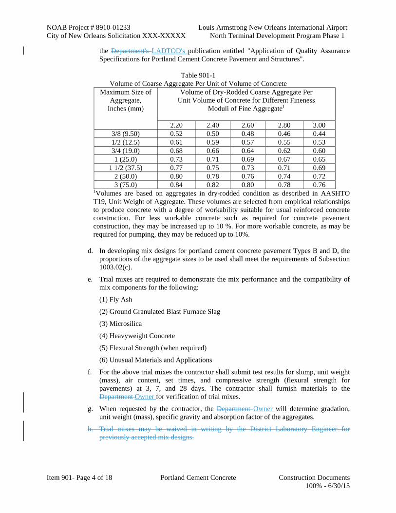
NOAB Project # 8910-01233 Louis Armstrong New Orleans International Airport City of New Orleans Solicitation XXX-XXXXX North Terminal Development Program Phase 1
Item 901- Page 4 of 18 Portland Cement Concrete Construction Documents 100% - 6/30/15
the Department's LADTOD's publication entitled "Application of Quality Assurance Specifications for Portland Cement Concrete Pavement and Structures".
Table 901-1
Volume of Coarse Aggregate Per Unit of Volume of Concrete Maximum Size of
Aggregate, Inches (mm)
Volume of Dry-Rodded Coarse Aggregate Per Unit Volume of Concrete for Different Fineness
Moduli of Fine Aggregate1
2.20 2.40 2.60 2.80 3.00 3/8 (9.50) 0.52 0.50 0.48 0.46 0.44 1/2 (12.5) 0.61 0.59 0.57 0.55 0.53 3/4 (19.0) 0.68 0.66 0.64 0.62 0.60 1 (25.0) 0.73 0.71 0.69 0.67 0.65
1 1/2 (37.5) 0.77 0.75 0.73 0.71 0.69 2 (50.0) 0.80 0.78 0.76 0.74 0.72 3 (75.0) 0.84 0.82 0.80 0.78 0.76
1Volumes are based on aggregates in dry-rodded condition as described in AASHTO T19, Unit Weight of Aggregate. These volumes are selected from empirical relationships to produce concrete with a degree of workability suitable for usual reinforced concrete construction. For less workable concrete such as required for concrete pavement construction, they may be increased up to 10 %. For more workable concrete, as may be required for pumping, they may be reduced up to 10%.
d. In developing mix designs for portland cement concrete pavement Types B and D, the proportions of the aggregate sizes to be used shall meet the requirements of Subsection 1003.02(c).
e. Trial mixes are required to demonstrate the mix performance and the compatibility of mix components for the following:
(1) Fly Ash
(2) Ground Granulated Blast Furnace Slag
(3) Microsilica
(4) Heavyweight Concrete
(5) Flexural Strength (when required)
(6) Unusual Materials and Applications
f. For the above trial mixes the contractor shall submit test results for slump, unit weight (mass), air content, set times, and compressive strength (flexural strength for pavements) at 3, 7, and 28 days. The contractor shall furnish materials to the Department Owner for verification of trial mixes.
g. When requested by the contractor, the Department Owner will determine gradation, unit weight (mass), specific gravity and absorption factor of the aggregates.
h. Trial mixes may be waived in writing by the District Laboratory Engineer for previously accepted mix designs.
Louis Armstrong New Orleans International Airport NOAB Project # 8910-01233 North Terminal Development Program Phase 1 City of New Orleans Solicitation XXX-XXXXX
Construction Documents Portland Cement Concrete Item 901 - Page 5 of 18 100% - 6/30/15
i.h. The minimum cement factors may be waived in writing by the District Laboratory EngineerOAR provided the contractor's mix design meets the average compressive strengths in Table 901-3 plus the over-design compressive strengths in Table 901-4.
Quality Control Tests: The contractor shall be responsible for determining gradation and moisture content of fine and coarse aggregates used in the concrete mixture and for testing the mixture at the job site for slump, unit weight (mass), temperature, and air content (when used). The contractor shall conduct operations to produce a mix complying with the reviewed and accepted mix design, except that variations will be permitted within specified control limits for individual samples. Test results for gradation, slump, unit weight (mass), and air content shall be plotted on control charts for individual samples. These control charts shall be submitted to the engineerOAR.
a. Times at which to obtain control test samples shall be set by the contractor using random number tables in accordance with DOTD S 605 or by random selection. Gradation control limits of aggregates shall be as shown in Subsection 1003.02. When required, additional test samples shall be taken as directed for slump, concrete temperature, and air content.
b. The minimum number of quality control tests to be performed by the contractor for structural and pavement concrete shall be in accordance with the Materials Sampling Manual. For minor structure concrete only, the contractor will not be required to have a Certified Concrete Technician or Authorized Concrete Field Tester, but shall implement a quality control testing program to ensure that the concrete meets the requirements of these specifications.
c. When producing concrete for Types B and D pavements, gradations shall be determined daily on each stockpile of aggregate to be used. All gradation calculations shall be based on percent of dry weight (mass). Upon determination of the gradation of each stockpile, the percent of the total aggregates retained shall be determined mathematically based on the proportions of the combined aggregate blend, and checked for conformance with Table 1003-1A.
Mix Adjustments: With prior notification given to the engineerOAR, the contractor may adjust the ratio of fine to coarse aggregate as reviewed and accepted, by no more than 5 percent. In no case shall it be adjusted so as to materially affect the volume of concrete. If the proportions of the aggregate sizes used do not satisfy the gradation requirements of Subsection 1003.02(c) due to changes in the gradation of one or more stockpiles, the proportions shall be adjusted to bring the combined aggregates back within specification limits. These minor adjustments for gradation will not require a new mix design. The mix produced shall be uniform, workable and within the specification limits of Table 901-3. When plant operations do not produce a uniform and workable mix, plant operations shall cease and corrective action shall be taken prior to restart.
a. When tendency of individual slump, air content, concrete temperature, or gradation measurements, as plotted on control charts, indicates that the mix is not uniform and may fall outside tolerance limits, the contractor shall immediately make adjustments to keep the mix within specified limits. If the contractor fails to make proper adjustments and the mix deviates from specification requirements or if the mix is obviously defective, the mix will be rejected.
b. For workability properties only, changes in mix proportions will be permitted provided the water-cement ratio is not exceeded, minimum cement factor is maintained, proper batch adjustments are made, and prior notification is given to the engineerOAR.
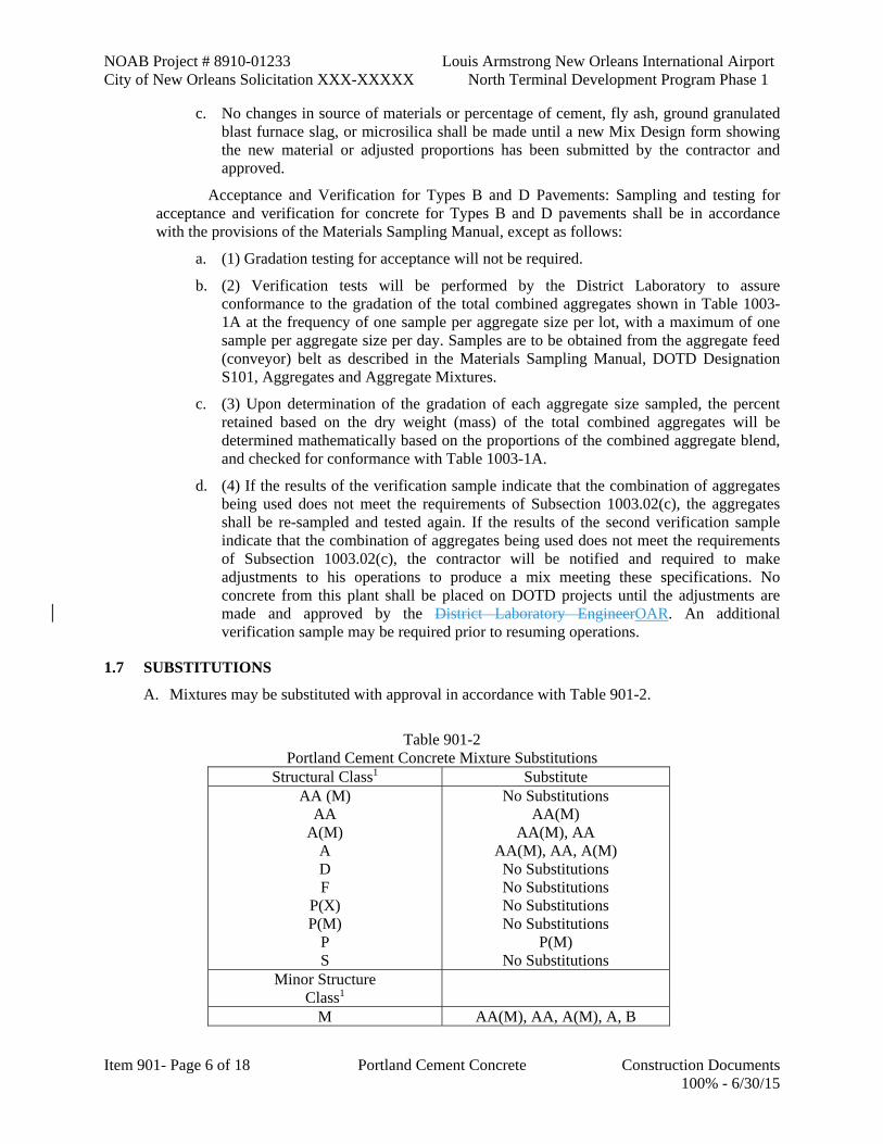
NOAB Project # 8910-01233 Louis Armstrong New Orleans International Airport City of New Orleans Solicitation XXX-XXXXX North Terminal Development Program Phase 1
Item 901- Page 6 of 18 Portland Cement Concrete Construction Documents 100% - 6/30/15
c. No changes in source of materials or percentage of cement, fly ash, ground granulated blast furnace slag, or microsilica shall be made until a new Mix Design form showing the new material or adjusted proportions has been submitted by the contractor and approved.
Acceptance and Verification for Types B and D Pavements: Sampling and testing for acceptance and verification for concrete for Types B and D pavements shall be in accordance with the provisions of the Materials Sampling Manual, except as follows:
a. (1) Gradation testing for acceptance will not be required.
b. (2) Verification tests will be performed by the District Laboratory to assure conformance to the gradation of the total combined aggregates shown in Table 1003-1A at the frequency of one sample per aggregate size per lot, with a maximum of one sample per aggregate size per day. Samples are to be obtained from the aggregate feed (conveyor) belt as described in the Materials Sampling Manual, DOTD Designation S101, Aggregates and Aggregate Mixtures.
c. (3) Upon determination of the gradation of each aggregate size sampled, the percent retained based on the dry weight (mass) of the total combined aggregates will be determined mathematically based on the proportions of the combined aggregate blend, and checked for conformance with Table 1003-1A.
d. (4) If the results of the verification sample indicate that the combination of aggregates being used does not meet the requirements of Subsection 1003.02(c), the aggregates shall be re-sampled and tested again. If the results of the second verification sample indicate that the combination of aggregates being used does not meet the requirements of Subsection 1003.02(c), the contractor will be notified and required to make adjustments to his operations to produce a mix meeting these specifications. No concrete from this plant shall be placed on DOTD projects until the adjustments are made and approved by the District Laboratory EngineerOAR. An additional verification sample may be required prior to resuming operations.
1.7 SUBSTITUTIONS
A. Mixtures may be substituted with approval in accordance with Table 901-2.
Table 901-2
Portland Cement Concrete Mixture Substitutions Structural Class1 Substitute
AA (M) AA
A(M) A D F
P(X) P(M)
P S
No Substitutions AA(M)
AA(M), AA AA(M), AA, A(M)
No Substitutions No Substitutions No Substitutions No Substitutions
P(M) No Substitutions
Minor Structure Class1
M AA(M), AA, A(M), A, B

Louis Armstrong New Orleans International Airport NOAB Project # 8910-01233 North Terminal Development Program Phase 1 City of New Orleans Solicitation XXX-XXXXX
Construction Documents Portland Cement Concrete Item 901 - Page 7 of 18 100% - 6/30/15
R Y
AA(M), AA, A(M), A, B, M No Substitutions
Pavement Type1, 2 B D E
D B
No Substitutions 1The mixture being substituted shall meet the requirements of Table 901-3 and the mix design for its class or type. The compressive strength of the substituted mix shall meet the strength requirements of the original mixture specified. 2When justified in writing and approved by the engineerOAR, small irregular areas of paving projects using Types B or D concrete may be substituted with Class A concrete.
1.8 COMPOSITION OF CONCRETE
A. Type of cement and composition of concrete shall be in accordance with the requirements of this subsection and Table 901-3.
B. Cement: Allowable types of cement are as follows: Use Allowable Cement Types General Construction (Structural Class Concrete and Minor Structure Class Concrete)
Type I or II portland cement; Type IP portland-pozzolan cement; Type IS portland blast-furnace slag cement
Concrete Pavement Type I or II portland cement; Type IP portland-pozzolan cement; Type IS portland blast-furnace slag cement
Prestressed or Precast Concrete
Type I, II or III portland cement; Type IP portland-pozzolan cement; Type IS portland blast-furnace slag cement
For concrete placements having a least dimension of 48 inches (1200 mm) or greater or if designated on the plans or the project specifications as being mass concrete, the allowable cement type shall be Type II Portland cement, Type IP portland-pozzolan cement, or Type IS portland blastfurnace slag cement. The cement, or combination of cement and fly ash or ground granulated blast furnace slag, shall be certified to generate a heat of hydration of not more than 70 calories/gram (290 kJ/kg) at 7 days.
Due to the gradation of aggregate or other conditions, additional cement may be required to achieve minimum compressive strength.
When using only Types I or II portland cement in concrete mixes, fly ash conforming to Subsection 1018.15 or grades 100 or 120 ground granulated blast-furnace slag conforming to Subsection 1018.27 may be partially substituted for portland cement on a pound (kilogram) for pound (kilogram) basis. The contractor may use a maximum of 25 percent fly ash by weight (mass) of cement for concrete pipe, up to 20 percent fly ash by weight (mass) of cement for other minor structures and concrete pavement, and up to 15 percent fly ash by weight (mass) of cement for structural concrete. In lieu of fly ash, the contractor may use grade 100 or grade 120 ground granulated blast-furnace slag up to 50 percent by weight (mass) of cement. The combination of slag and fly ash will not be allowed as a partial substitution for cement.
NOAB Project # 8910-01233 Louis Armstrong New Orleans International Airport City of New Orleans Solicitation XXX-XXXXX North Terminal Development Program Phase 1
Item 901- Page 8 of 18 Portland Cement Concrete Construction Documents 100% - 6/30/15
C. Chemical Admixtures: An air-entraining admixture will be required in paving concrete when placed by slip-form methods or when a central mixing plant or non-agitating haul trucks are used.
Air-entraining and water-reducing admixtures will be required in Class AA, F or AA(M) concrete. When an air-entraining admixture is used, the total air content of the concrete mix shall be tested in accordance with DOTD TR 202, and shall be as specified in Table 901-3.
A water-reducing admixture will be required for mass concrete.
When the ambient air temperature is 70°F (20°C) or below, the waterreducing admixture shall be the normal-set type. When the ambient air temperature is above 70°F (20°C) and below 85°F (30°C), the waterreducing admixture may be either the normal-set type or the set-retarding type. When the ambient air temperature is 85°F (30°C) or above, the waterreducing admixture shall be the set-retarding type, except for concrete containing fly ash or ground granulated blast furnace slag where this choice is optional. Set-retarding admixtures shall be used in an amount sufficient to produce the necessary retardation; however, the amount used shall not be less than is necessary to comply with Subsection 1011.02.
The contractor shall consider the influence of different materials and job conditions, including local weather on setting characteristics. With approval of the mix design, the contractor may use approved admixtures other than as stated above in order to control setting characteristics.
Admixtures shall comply with Subsection 1011.02 and be listed on QPL 58.
Water contents for superplasticized concrete mixes shall not be reduced to levels that will restrict cement hydration. The amount of water in the superplasticizer shall be included as a part of required mixing water. The dosage of superplasticizer may be adjusted depending on the consistency of the mix.
Final slump of superplasticized concrete shall be appropriate for its application. It shall not exhibit excessive bleeding or segregation of aggregates as determined by the project engineerOAR.
The method of adding and mixing the superplasticizer to the mix shall be as recommended by the manufacturer.
When multiple admixtures are used, the admixtures shall be manufactured by the same company and shall be compatible.
The use of admixtures in other classes or types of concrete will be optional with the contractor with written approval.
D. Water: The total amount of water in the mixture, including admixtures and free water, shall not exceed the maximum water-cement ratio specified in Table 901-3. Free water shall include all water entering the mix with the aggregates, except water absorbed by the aggregate.
Because of the absorptive nature of lightweight aggregate and the inability to obtain a true saturated surface dry condition for determining free moisture, a maximum amount of water cannot be specified for Class Y concrete. The slump requirement of Table 901-3 or as specified will be the governing factor in determining maximum allowable water.
E. Aggregate: All aggregates for use in portland cement concrete shall meet the requirements of Subsection 1003.01.
Coarse Aggregate: Coarse aggregate, except for gradations for Types B and D pavements, shall be the grade specified in Table 901-3 and shall comply with the requirements of Subsection 1003.02(b).

Louis Armstrong New Orleans International Airport NOAB Project # 8910-01233 North Terminal Development Program Phase 1 City of New Orleans Solicitation XXX-XXXXX
Construction Documents Portland Cement Concrete Item 901 - Page 9 of 18 100% - 6/30/15
Fine Aggregate: Fine aggregate, except for gradations for Types B and D pavements, shall comply with the requirements of Subsection 1003.02(a).
Aggregates for Types B and D Pavements: Aggregates shall comply with the requirements of Subsection 1003.02(c).
1.9 EQUIPMENT
A. General: Sufficient plant capacity and transporting equipment to ensure delivery at the required rate shall be provided. Rate of concrete delivery during concreting operations shall provide for proper handling, placing and finishing of concrete and maintain a workable surface. Methods of delivering and handling concrete shall facilitate placing with a minimum of rehandling and without damage to the structure or concrete.
B. Plant Equipment: Batch plants shall include approved storage, weigh hoppers, and measuring devices. Equipment shall be properly sealed and vented to minimize dusting and loss of material. Materials shall be incorporated into the mix by methods that will ensure uniform distribution. The amount of each material used in the mix shall be recorded and certified by the contractor's authorized representative.
The plant shall be equipped with adequate water storage and a device for automatically controlling the amount of water used in each batch.
For plants using direct-fill elevating weigh hoppers, computer controlled indicator lights may be used as an indication of aggregate weights but shall not be the sole means of control for aggregate proportioning. Means of control shall be provided so that, as the quantity desired in the weigh hopper is approached, material may be added slowly and shut off with precision. Weigh hoppers shall be constructed as to eliminate accumulation of materials and to discharge completely. Suitable provisions shall be made for removal of overload from the hopper by the operator. Approved radio communication shall be provided between the concrete batcher and front-end loader operator. Actual weights of material batched each time shall be entered on the Batch Certification Form. The plant shall demonstrate satisfactory performance by producing consistent concrete with adequate compressive strengths.
a. Storage Bins and Silos: For plants with overhead storage bins, which feed directly into the weigh hopper, or storage bins with belt feed to the weigh hopper, the bins shall have adequate separate compartments for fine aggregate and each size of coarse aggregate. Each compartment shall be designed to discharge efficiently and freely into the weigh hopper. Means of control shall be provided so that, as the quantity desired in the weigh hopper is approached, material shall be added slowly and shut off with precision.
1) Silos shall be weatherproof, sealed, free of holes, and shall prevent contamination. Silos shall be designed to freely discharge and shall be equipped with vibrators to maintain flow of material and prevent accumulation. Silos shall be designed with sufficient capacity for the operation. Silos shall be provided with a positive means of shut off without leaking into the weigh hopper. A separate silo shall be used for each dry bulk material added to the mix. If a silo is divided into compartments for cement, fly ash, ground granulated blast furnace slag and microsilica, a positive means of separation shall be provided.
b. Measuring Devices: Materials shall be measured by weighing except where other methods are authorized.
1) Batch plants may be equipped to proportion materials by approved automatic weighing devices. Moisture probes can be used to determine the moisture content

NOAB Project # 8910-01233 Louis Armstrong New Orleans International Airport City of New Orleans Solicitation XXX-XXXXX North Terminal Development Program Phase 1
Item 901- Page 10 of 18 Portland Cement Concrete Construction Documents 100% - 6/30/15
of aggregates for batch adjustment provided the accuracy is confirmed by the engineer OAR to be within 0.5 percent of the results obtained by the Certified Concrete Technician in accordance with DOTD TR 106.
2) Fine aggregate and each size of coarse aggregate from separate bins shall be weighed either separately or cumulatively on scales in the weigh hopper. The allowable quantities of bulk fly ash, bulk ground granulated blast furnace slag, or bulk microsilica may be weighed cumulatively in the same hopper with the cement, provided the cement is weighed first and the scale system is separate from that used for the aggregates.
3) Weigh hoppers shall be constructed to eliminate accumulation of materials and to discharge completely. Suitable provisions shall be made for removal of an overload from the hopper by the operator.
4) Scales shall be accurate to 0.5 percent throughout the range of use. Maximum graduation on scales shall be 0.1 percent of the rated scale capacity. When beam type scales are used, poises shall be designed to be locked in any position to prevent accidental change of position, and the weigh beam and a telltale device shall be in view of the operator. Plant and laboratory measuring devices shall be subject to approval and shall be tested, inspected, and certified by a qualified independent scale service or the Weights and Measures Division of the Louisiana Department of Agriculture and Forestry at no cost to the Department Owner every 90 calendar days, and more often when the engineer OAR deems it necessary to assure their accuracy.
5) Individual aggregates shall be batched within 2 percent, and the total weight (mass) of aggregate shall be within 1 percent of the required weight (mass).
6) Cement, fly ash, ground granulated blast furnace slag, and microsilica shall be within 1 percent of the required weight (mass). Cement in standard bags need not be weighed; however, when used, they shall be used in full bag increments and the quantities of other materials shall be adjusted accordingly. Bagged fly ash and bagged ground granulated blast furnace slag will not be allowed.
7) Mixing water shall be measured by volume or weight (mass). Water measuring devices shall be accurate to 1 percent at 1/2 the maximum allowable water per batch and the maximum graduation shall be 1 gallon (4 L).
8) Approved methods and equipment for adding air-entraining admixtures or other admixtures into the batch shall be used. The quantity of admixtures shall be measured into the mixer with an accuracy of 3 percent. Admixtures shall be mechanically dispensed in a liquid state with the mixing water. A separate dispensing device shall be provided for each admixture.
c. Ticket Printer System: Certified concrete plants may be equipped with an approved automatic ticket printer system for recording required batching information. When an automatic ticket printer system is not used, quantities and batching information shall be determined by visual observation, recorded, and certified correct by the contractor's authorized representative.
1) The approved ticket printer system shall be tamper-proof and shall print time of batching, amount of water, batch weights, moisture content of aggregates, and quantities of admixtures. The Certified Concrete Technician may add moisture content of aggregates or quantities of admixtures to the printed ticket when the

Louis Armstrong New Orleans International Airport NOAB Project # 8910-01233 North Terminal Development Program Phase 1 City of New Orleans Solicitation XXX-XXXXX
Construction Documents Portland Cement Concrete Item 901 - Page 11 of 18 100% - 6/30/15
automatic system does not have these capabilities. During a breakdown, quantities shall be determined by visual observation and certified as stated above.
2) All records of batches shall show batch number, day, month, year, and time of day to the nearest minute for each batch. The maximum quantity of water that can be added at the jobsite shall be shown on the batch ticket. The engineer OAR shall be provided with a legible copy of all batch records identified with lot number and mix design number.
d. Hauling Equipment: Hauling equipment shall be watertight and shall be capable of discharging concrete at a satisfactorily controlled rate without segregation.
1) Truck Mixer: Truck mixers shall be the revolving drum type, equipped with pressurized, calibrated tanks for carrying a portion of the mixing water.
a) Pick-up and throw-over blades in the mixing drum shall be replaced when worn beyond the limit recommended by the manufacturer. The contractor shall have available a copy of the manufacturer's design, showing dimensions and arrangements of blades in reference to original height and depth.
b) Only the prescribed and verifiable amount of water is permitted in the tank unless the tank is equipped with a device by which the quantity of water added can be readily verified. Truck mixers shall be equipped with electrically or mechanically actuated revolution counters, which display the number of revolutions. Counters shall be located to provide safe and convenient inspection.
c) Each truck mixer shall have attached thereto in a prominent place a metal plate on which is plainly marked the uses for which the equipment is designed, the maximum rated capacity of the drum in terms of concrete volume and rotation speed for both agitating and mixing speeds.
d) Truck mixers shall be equipped with means for accurately measuring the amount of water used in each batch.
2) Agitator Hauling Equipment: Agitators shall be supplied with adequate mixing blades or paddles to agitate the mix and prevent segregation. Covers shall be provided when directed.
a) Each agitator shall have attached thereto in a prominent place a metal plate on which is plainly marked the uses for which the equipment is designed, the maximum rated capacity in terms of concrete volume, and agitation speed.
3) Non-Agitator Hauling Equipment: The bodies of nonagitating hauling equipment shall be smooth, metal, and mortar tight containers. Covers shall be provided when directed.
e. Portable Mixers: Portable mixers shall have a minimum capacity of one cubic yard (cu m) and shall be capable of uniformly mixing and discharging concrete without segregation.
1.10 BATCHING AND MIXING
A. General: Concrete shall be thoroughly mixed in a mixer of an approved size and type, which will ensure uniform distribution of materials through the mass.
Pick-up and throw-over blades or mixing paddles in the mixing drum or mixing unit shall be replaced when worn beyond the limit recommended by the manufacturer. The contractor shall
NOAB Project # 8910-01233 Louis Armstrong New Orleans International Airport City of New Orleans Solicitation XXX-XXXXX North Terminal Development Program Phase 1
Item 901- Page 12 of 18 Portland Cement Concrete Construction Documents 100% - 6/30/15
have available a copy of the manufacturer's design, showing dimensions and arrangements of blades in reference to original height and depth.
Mixing operations shall begin within 30 minutes after addition of cement to the aggregates. When cement is charged into a mixer drum containing surface-wet aggregate and the ambient temperature is above 90°F (32°C), or when high early strength cement is used, this limit shall be reduced to 15 minutes. When there is an interruption to the mixing operations, the mixer shall be thoroughly cleaned. The entire contents of the mixer shall be removed from the drum before materials for a succeeding batch are placed therein. Materials composing a batch shall be deposited simultaneously in an operating mixer. A portion of mixing water shall enter in advance of cement and aggregates. No mixer having a rated capacity of less than one cubic yard (cu m) shall be used nor shall a mixer be charged in excess of its rated capacity. The minimum size batch shall be one cubic yard (cu m). Mixers with worn blades or excessive build-up will be rejected. Concrete exposed to salt water or a corrosive environment shall be mixed for 2 minutes and the water content of the mixture shall be carefully controlled.
B. Central Plant and Site Mixing: Concrete shall be mixed for at least 50 seconds. Mixing time shall begin after all materials, including water, are in the mixer. Mixing time ends when the discharge chute opens. The mixer shall be equipped with an approved timing device, which will automatically lock the discharge lever when the drum has been charged and release it at the end of the mixing period. During mixing, the mixer shall be operated at a drum speed for which it has been designed as shown on the manufacturer's name plate on the mixer.
C. Truck Mixing: Aggregates, cement, fly ash, ground granulated blast furnace slag and microsilica for concrete shall be measured in accordance with Subsection 901.09 and charged into the drum at the proportioning plant.
Size of batch in truck mixers shall not exceed the maximum rated mixing capacity of the mixer as stated by the manufacturer and stamped on a metal plate on the mixer. When a truck mixer is used for complete mixing, each batch shall be mixed for not less than 70 nor more than 130 revolutions of the mixer drum at the rate of rotation designated as the mixing speed by the equipment manufacturer on the metal plate on the mixer. Any additional mixing shall be at the speed designated by the equipment manufacturer as the agitating speed. All materials, including mixing water, shall be in the mixer drum before actuating the revolution counter or taking an initial reading.
When the prescribed amount of water is added at the batch plant and slump is on the low side at the jobsite it will be permissible to add a minimum of 75 percent of the mixing water at the time cement and aggregates are added at the batch plant and the remaining mixing water at the job site prior to discharging concrete into forms. Water added at the job site may be added in 1 or 2 increments with additional mixing within the range of 20 to 30 revolutions at designated mixer speed for each increment; however, the total of 130 revolutions shall not be exceeded. Water added at the jobsite shall not cause the maximum allowable watercement ratio or slump of the batch to be exceeded.
If water or superplasticizer is allowed to be added to a partial load, only a proportional amount will be added. The method of adding and mixing superplasticizer to the mix shall be in accordance with the manufacturer's recommendation. When the slump is more than the maximum specification limit, the batch will be rejected; additional mixing or agitation to reduce the slump will not be allowed even though the maximum time limit or number of revolutions have not been exceeded.
Slump tests, unit weight (mass), acceptance cylinders, and temperature measurements will not be made until all mixing water has been added to the batch.

Louis Armstrong New Orleans International Airport NOAB Project # 8910-01233 North Terminal Development Program Phase 1 City of New Orleans Solicitation XXX-XXXXX
Construction Documents Portland Cement Concrete Item 901 - Page 13 of 18 100% - 6/30/15
D. Partial Mixing at Central Plant: When partial mixing is allowed at a central plant, the mixing time at the central plant may be reduced to 30 seconds. Additional required mixing shall be completed in a truck mixer at mixing speed. Mixing time in the truck mixer shall be a minimum of 10 and a maximum of 70 revolutions.
E. Time Limitations: The maximum allowable time from the addition of cement to the mix to complete discharge of the concrete shall be 90 minutes or a maximum of 300 revolutions, whichever may occur first. When transport is by non-agitator truck, the maximum allowable time from the addition of cement to the mix to complete discharge of the concrete shall be 45 minutes. In hot weather or any other conditions contributing to rapid loss of plasticity or uniformity of concrete, maximum allowable time may be reduced by the engineerOAR.
F. Hauling Equipment: Wet batches of concrete may be transported in a truck mixer, agitator or other approved equipment. Nonagitator trucks will not be allowed for structural concrete, but will be permitted for pavement concrete when air-entrainment admixture is used. Maximum volume of mixed concrete transported in an agitator truck at agitation speed shall be in accordance with the manufacturer's specified rating.
G. Portable Mixing: Portable mixers shall be approved in writing for mixing one cubic yard (cu m) of concrete or less per day for minor structure concrete.
H. Delivery: Sufficient plant capacity and transporting apparatus to insure delivery at the required rate shall be provided. Rate of concrete delivery during concreting operations shall be such as to provide for proper handling, placing and finishing of concrete and maintain a workable surface. Methods of delivering and handling concrete shall be such as will facilitate placing with a minimum of handling and without damage to the structure or concrete.
1.11 TEMPERATURE LIMITATIONS
A. General: Air temperature and mix temperature shall be determined at the point of placement in the shade away from artificial heat.
B. Hot Weather Limitations: Hot weather limitations shall apply to concrete for:
Bridge Decks, Approach Slabs, and Mass Concrete: Hot weather concreting practices will be required when the job site temperature in the shade and away from artificial heat is 80°F (27°C) and rising. When internal temperature of plastic concrete reaches 85°F (30°C), the contractor shall prevent the temperature of succeeding batches from going beyond 90°F (32°C) by approved methods. If necessary, forms shall be precooled by approved methods immediately prior to concrete placement.
Pavement Concrete: Internal temperature of the plastic concrete shall not exceed 95°F (35°C) at the time of placement.
C. Cold Weather Limitations: Mixing and concreting operations for concrete mixes not containing ground granulated blast-furnace slag or Type IS cement shall be discontinued when a descending air temperature in the shade and away from artificial heat reaches 40°F (5°C), and shall not be resumed until an ascending air temperature in the shade and away from artificial heat reaches 35°F (2°C) provided the high temperature forecasted by the U.S. Weather Service is above 40°F (5°C). For concrete mixes containing ground granulated blast-furnace slag or Type IS cement, operations shall be discontinued at a descending air temperature in the shade and away from artificial heat of 55°F (13°C) and can resume at a temperature of 50°F (10°C) and rising provided the high temperature forecasted by the U.S. Weather Service is above 55°F (13°C). Production shall not begin until the temperature at the point of placement is within the above limitations. Concrete shall not be placed if the U.S. Weather Service forecasts the

NOAB Project # 8910-01233 Louis Armstrong New Orleans International Airport City of New Orleans Solicitation XXX-XXXXX North Terminal Development Program Phase 1
Item 901- Page 14 of 18 Portland Cement Concrete Construction Documents 100% - 6/30/15
temperature to be less than 35°F (2°C) within the 24 hour period following placement unless authorized in writing.
When concrete placement at lower air temperatures is authorized in writing, aggregates may be heated by either steam or dry heat prior to being placed in the mixer. The apparatus used shall heat the mass uniformly and shall be arranged to prevent occurrence of overheated areas. If the air temperature is less than 35°F (2°C) at the time of placing concrete, the engineer OAR may require water or aggregates to be heated to not less than 70°F (20°C) nor more than 150°F (65°C). After placement, the concrete shall be protected by additional covering, insulating materials, or other methods approved by the engineerOAR.
1.12 ACCEPTANCE AND PAYMENT SCHEDULE
A. Acceptance and payment schedules in Table 901-5 will apply to all cast-in-place structural portland cement concrete. Acceptance and payment schedules in Table 901-6 will apply to all minor structure portland cement concrete. Acceptance and payment schedules for portland cement concrete pavement are shown in Table 601-1 of Section 601. These schedules do not apply to precast concrete.

Louis Armstrong New Orleans International Airport NOAB Project # 8910-01233 North Terminal Development Program Phase 1 City of New Orleans Solicitation XXX-XXXXX
Construction Documents Portland Cement Concrete Item 901 - Page 15 of 18 100% - 6/30/15
Table 901-3 Master Proportion Table for Portland Cement Concrete
Average Compressive Strength, psi (MPa) at 28
days
Grade of Coarse
Aggregate
Min. Cement, lb/yd3
(kg/m3) of Concrete 9,14
Maximum Water/Cement
ratio, lb/lb (kg/kg) 1,9
Total Air Content
(Percent by volume) 4
Slump Range 10, inches (mm) Non-Vibrated Vibrated Slip Form
Paving 2
Structural Class 11 AA(M)
AA A(M)
A D F
P(X) P(M)
P S
4400 (30.4) 4200 (29.0) 4400 (30.4) 3800 (26.2) 3300 (22.8)
3400 (23.5)5 7500 (51.7) 5 6000 (41.4)5 5000 (34.5)5 3800 (26.2)
A, P A, P A, P
A, F 8, P A, B, D, P
A,P A, F 8, P A, F 8, P A, F 8, P
A,P
560 (332) 560 (332) 510 (302) 510 (302) 420 (249) 460 (273) 700 (415) 600 (356) 560 (332) 650 (385)
0.44 0.44 0.53 0.53 0.58 0.44 0.40 0.44 0.44 0.53
5±1 5±1 5±2 5±2 5±2 5±1 5±2 5±2 5±2 5±2
2-5 (50-125) 2-5 (50-125) 2-5 (50-125) 2-5 (50-125) 2-5 (50-125) 2-5 (50-125)
N.A. N.A. N.A.
6-8 (150-200)
2-4 (50-100) 2-4 (50-100) 2-4 (50-100) 2-4 (50-100) 1-3 (25-75)
2-4 (50-100) 2-10 (50-250) 2-6 (50-150)7 2-6 (50-150)7
N.A
N.A. N.A. N.A.
1-2.5 (25-65) N.A. N.A. N.A. N.A. N.A. N.A.
Minor Structure Class 11 M R Y
3000 (20.7) 1800 (12.4) 3000 (20.7)
A, B, P A, B, D, P
Y
470 (279) 370 (219) 560 (332)
0.56 0.70
-3
5±2 5±2 6-9
2-5 (50-125) 2-5 (50-125)
N.A
2-4 (50-100) 2-4 (50-100) 1-3 (25-75)
1-2.5 (25-65) N.A. N.A.
Pavement Type 11
B D E
4000 (27.6)6 4000 (27.6)6 4000 (27.6)6
N/A13 N/A13
A, F12, P
475 (282) 450 (267) 600 (356)
0.53 0.53 0.40
5±2 5±2 5±2
N.A. N.A. N.A.
2-4 (50-100) 2-4 (50-100) 2-4 (50-100)
1-2.5 (25-65) 1-2.5 (25-65) 1-2.5 (25-65)
N.A. – Not Applicable 1 Except for Class AA, AA(M), or F concrete, the maximum volume of water; gal. (L), shall be reduced 5 percent when a water-reducing admixture is used, and 10 percent when an air entraining admixture, or air-entraining and water-reducing admixtures, is used. When the coarse aggregate portion of the mix is 100 percent crushed aggregate, the water may be increased by 5 percent provided the maximum water listed in Table 901-3 is not exceeded. 2 Also slump range for other concrete placed by extrusion methods. 3 Refer to Subsection 901.08(c).

NOAB Project # 8910-01233 Louis Armstrong New Orleans International Airport City of New Orleans Solicitation XXX-XXXXX North Terminal Development Program Phase 1
Item 901- Page 16 of 18 Portland Cement Concrete Construction Documents 100% - 6/30/15
4 Total air content ranges when air-entrainment is allowed or specified. Air content shall be designed at midrange. See Subsection 901.08(b). 5 Values shown represent the minimum compressive strengths allowed. 6 Average compressive strengths for Pavement Type concrete shall be 3600 psi (25.0 MPa) when air-entrainment is used. 7 No more than a 2 inch (50 mm) slump differential for any design pour. 8 Grade F coarse aggregate shall be used only when specified or permitted. The minimum cement content shall be increased when this aggregate is used. 9 For mixes including partial replacement of cement with fly ash or ground granulated blast furnace slag, the minimum cement and maximum water contents shown apply to the total
cement and fly ash or ground granulated blast furnace slag content of the mix. Additional cement may be required to achieve minimum compressive strength. 10 When a slump range is specified in other sections, that range shall govern. 11 See Subsection 901.08(a) for allowable types of cement. 12 For use in partial depth patching. 13 Aggregate grading shall comply with the requirements of Subsection 1003.02(c). 14 The minimum cement factors may be waived in writing by the District Laboratory EngineerOAR in accordance with Subsection 901.06(a).

Louis Armstrong New Orleans International Airport NOAB Project # 8910-01233 North Terminal Development Program Phase 1 City of New Orleans Solicitation XXX-XXXXX
Construction Documents Portland Cement Concrete Item 901 - Page 17 of 18 100% - 6/30/15
Table 901-4
Over-Design to Meet Compressive Strength Requirements1
Number2,3,5
of Tests
Standard Deviation, psi (MPa)4 300 (2.1) 400 (2.8) 500 (3.4) 600 (4.1) 700 (4.8)
Additional Compressive Strength, psi (MPa) 15-19 470 (3.2) 620 (4.3) 850 (5.9) 1,120 (7.7) 1,390 (9.6) 20-29 430 (3.0) 580 (4.0) 760 (5.2) 1,010 (7.0) 1,260 (8.7)
30 or More 400 (2.8) 530 (3.7) 670 (4.6) 900 (6.2) 1,130 (7.8)
1When designing the mix, add the tabulated amounts to the average compressive strength at 28 days shown in Table 901-3. 2Number of tests of a concrete mixture used to estimate the standard deviation of a concrete production facility. Test of another mix within 1,000 psi (6.9 MPa) of the specified strength may be used. 3If less than 15 prior tests are available the over-design should be 1,000 psi (6.9 MPa) for specified strength less than 3,000 psi (20.7 MPa), 1,200 psi (8.3 MPa) for specified strengths from 3,000 to 5,000 psi (20.7 to 34.5 MPa) and 1,400 psi (9.7 MPa) for specified strengths greater than 5,000 psi (34.5 MPa). 4Interpolation between standard deviations is required. 5A strength test result is defined as the average strength of all specimens of the same age, fabricated from a sample taken from a single batch of concrete. A strength test cannot be based on only one cylinder; a minimum of two cylinders is required for each test.
Table 901-5E
Acceptance and Payment Schedules Cast-In-Place Structural Concrete
Average Compressive Strength per Lot, psi (28 to 31 days) Class A or S Class AA Class A(M) or
AA(M) Class D Class F Percent of
Contract Price1 3800 & above 4200 & above 4400 & above 3300 & above 3400 & above 100
3400-3799 3800-4199 4200-4399 3000-3299 --- 98 3000-3399 3500-3799 4000-4199 2500-2999 --- 90
Below 3000 Below 3500 Below 4000 Below 2500 Below 3400 50 or remove
and replace2
Table 901-5M
Acceptance and Payment Schedules Cast-In-Place Structural Concrete
Average Compressive Strength per Lot, MPa (28 to 31 days) Class A or S Class AA Class A(M)
or AA(M) Class D Class F Percent of
Contract Price1 26.2 & above 29.0 & above 30.4 & above 22.8 & above 23.5 & above 100
23.5- 26.1 26.2-28.9 29,0-30.3 20.7-22.7 --- 98 20.7-23.4 24.1-26.1 27.6-28.9 17.2-20.6 --- 90
Below 20.7 Below 24.1 Below 27.6 Below 17.2 Below 23.5 50 or remove and replace2

NOAB Project # 8910-01233 Louis Armstrong New Orleans International Airport City of New Orleans Solicitation XXX-XXXXX North Terminal Development Program Phase 1
Item 901- Page 18 of 18 Portland Cement Concrete Construction Documents 100% - 6/30/15
1When concrete is part of an item or not a direct pay item, lot sizes, sampling and acceptance testing for the required quantities will be in accordance with Subsection 805.18. The value for each cubic yard (cu m) required will be assessed at $350 ($460) for the purpose of applying payment adjustment percentages. The amount of payment adjustment for the quantity of concrete involved will be deducted from payment.
Acceptance and payment schedules shall apply to the contract item itself for cast-in-place piling.
2When the average compressive strength of any batch in a lot is less than 4000 psi (27.6 MPa) for Class A(M) or AA(M), less than 3500 psi (24.1 MPa) for Class AA, less than 3000 psi (20.7 MPa) for Class A or S, less than 2500 psi (17.2 MPa) for Class D, or less than 3400 psi (23.5 MPa) for Class F, an investigation will be made. If concrete is allowed to remain in place, payment will be based on the average compressive strength for the lot. If concrete is not allowed to remain in place, the identifiable deficient areas shall be removed and replaced at no direct pay.
When the average compressive strength for a lot is less than 4000 psi (27.6 MPa) for Class A(M) or AA(M), less than 3500 psi (24.1 MPa) for Class AA, less than 3000 psi (20.7 MPa) for Class A or S, less than 2500 psi (17.2 MPa) for Class D, or less than 3400 psi (23.5 MPa) for Class F, an investigation will be made. If concrete is allowed to remain in place, payment for the lot will be based on 50 percent of the contract price.
Any cores obtained in these investigations will be used for evaluation purposes only and payment will be based on original acceptance samples.
Table 901-6E Acceptance and Payment Schedules
Cast-In-Place Minor Structure Concrete Average Compressive Strength, psi (28 to 31 days)
Class M or Y Class R Percent of Contract Price 1
3000 & Above Below 3000
1800 & Above Below 1800
100 50 or Remove 2
Table 901-6M
Acceptance and Payment Schedules Cast-In-Place Minor Structure Concrete
Average Compressive Strength, MPa (28 to 31 days) Class M or Y Class R Percent of
Contract Price 1 20.7 & Above
Below 20.7 12.4 & Above
Below 12.4 100
50 or Remove 2 1When concrete is part of an item or not a direct pay item, sampling and acceptance testing for the required quantities shall be in accordance with this section. The value for each cubic yard (cu m) of concrete required will be assessed at $350 ($460) for the purpose of applying payment adjustment percentages. The amount of payment adjustment for the quantity of concrete involved will be deducted from payment. 2When the average compressive strength is less than 3,000 psi (20.7 MPa) for Class M or Y, and 1,800 psi (12.4 MPa) for Class R, an investigation will be made. If concrete is allowed to remain in place, payment will be based on 50 percent of the contract price. Any cores obtained in these investigations will be used for evaluation purposes only. Payment will be based on original acceptance samples.
Louis Armstrong New Orleans International Airport NOAB Project # 8910-01233
North Terminal Development Program Phase 1 City of New Orleans Solicitation XXX-XXXXX
100% Construction Documents Signs and Pavement Markings Section 1015 - Page 1 of 20
6/30/15
SECTION 1015 – SIGNS AND PAVEMENT MARKINGS
PART 1 - GENERAL
1.1 GENERAL REQUIREMENTS
A. The materials shall comply with these specifications, the plans and the MUTCD. When
directed, the contractor shall furnish and prepare samples for testing in accordance with
Department instructions.
1.2 METALS
A. Ferrous Metals:
1. Structural Steel: Structural steel for posts, stringers, framing and miscellaneous steel shall
comply with AASHTO M 270, Grade 36 (M 270M, Grade 250). Steel shall be galvanized
in accordance with Subsection 811.12.
2. Steel Pipe: Steel pipe or tubing for structures shall be Schedule 40 (STD) complying with
ASTM A 53, Type E or Type S Grade B, or hot formed tubing complying with ASTM A
36 (ASTM A 36M) and ASTM A 501.
3. Steel Posts for Small Signs, Markers and Delineators: Posts shall be steel of the flanged
channel type shown on the plans, galvanized after fabrication in accordance with
Subsection 811.12. Before fabrication, posts shall be within 3.5 percent of the specified
weight (mass).
a. Posts shall be fabricated from steel complying with either ASTM A 499, Grade 60 with
chemical properties conforming to ASTM A 1 for 91 -lb/yd (45 kg/m) or heavier rail
steel, or ASTM A 576, Grade 1080 with 0.10 percent -0.20 percent silicon. Holes 3/8
inch (10 mm) in diameter shall be drilled or punched through the middle of each post
on one inch (25-mm) centers for at least 36 inches (900 mm) from the top of each post.
B. Aluminum Alloy: Structural members shall be aluminum complying with ASTM B 221
(ASTM B 221M) or ASTM B 429, Alloy 6061-T6. Miscellaneous aluminum shall comply
with ASTM B 209 (ASTM B 209M), Alloy 6061-T6.
C. Fittings:
1. Structural Bolts, Nuts and Washers: High strength bolts shall be ASTM A 325 (ASTM A
325M), and other bolts shall be ASTM A 307, Grade A or Grade B. Bolts shall have
hexagonal heads and be supplied with two flat and one lock washer and hexagonal-head
nut. Bevel washers, where required, shall be wrought steel. Bolts, nuts and washers shall
be galvanized in accordance with ASTM A 153 or by an approved mechanical galvanizing
process complying with ASTM B 695 that provides the same coating thickness.
a. Anchor bolts shall be AASHTO M 270, Grade 36 (M 270M, Grade 250) steel except
the maximum tensile strength shall be 88,000 psi (605 MPa) and galvanized in
accordance with Subsection 811.12 unless otherwise specified.
b. Stainless steel bolts shall comply with ASTM A 320 (ASTM A 320M), Grade B 8,
annealed or approved equal.

NOAB Project # 8910-01233 Louis Armstrong New Orleans International Airport
City of New Orleans Solicitation XXX-XXXXX North Terminal Development Program Phase 1
Section 1015 - Page 2 of 20 Signs and Pavement Markings 100% Construction Documents
6/30/15
2. Fasteners: Fasteners used in fabricating sign faces, including splice plates for joining two
panels, sills and border angles, and attaching route marker shields shall be 1/4 inch (6 mm)
aluminum blind rivets that provide positive mandrel retention. These rivets shall have a
minimum tensile strength of 875 pounds (397 kg) and a minimum sheer strength of 850
pounds (386 kg).
a. Fasteners, used in attaching Interstate, Louisiana, and U.S. shields to the sign panel,
shall be manufactured from aluminum alloy with brasier heads, complying with ASTM
B 316 (ASTM B 316M), Alloy 2024-T4.
b. Fasteners used in attaching demountable legend to sign faces (except for shields) shall
be 1/8 inch (3 mm) diameter blind rivets manufactured from aluminum alloy
complying with ASTM B 316 (ASTM B 316M), Alloy 1100-H14.
c. Fasteners for delineator, object marker and milepost assemblies shall be vandal
resistant and will be subject to approval prior to use.
1.3 FLEXIBLE POSTS
A. Flexible posts for small signs, markers and delineators shall be approved products listed in QPL
39.
1.4 SIGN PANELS
A. Permanent Sign Panels: Flat panels shall be aluminum sheets or plates complying with ASTM
B 209, Alloy 6061-T6 or Alloy 5052-H38. Extruded aluminum panels shall comply with
ASTM B 221 (ASTM B 221M), Alloy 6063-T6 and after fabrication, have a flatness equal to
or less than 0.031 inch per foot of length and 0.004 inch per inch of width.
B. Temporary Sign Panels: Substrate for barricade panels shall be either wood or rigid
thermoplastic. Substrate for portable signs shall be aluminum, wood or plastic. Substrate for
post mounted signs shall be aluminum, wood, rigid thermoplastic or aluminum clad low density
polyethylene plastic.
1. Aluminum: Aluminum sheeting shall be 0.080 inch (2 mm) thickness complying with
ASTM B 209 (ASTM B 209M), Alloy 6061-T6 or Alloy 5052-H38.
2. Wood: Plywood sheeting of exterior type Grades either High Density Overlay or Medium
Density Overlay, are acceptable for use provided the following requirements are met.
a. Panels shall be a minimum of 5/8 inch (15 mm) thick and shall comply with the latest
American Plywood Association specifications and be identified with the APA edge
mark or back stamp to verify inspection and testing. Prior to application of reflective
sheeting, the surface shall be abraded with steel wool or fine sandpaper, and wiped
thoroughly clean. The surface shall be allowed to dry a minimum of 8 hours prior to
application of sheeting. Cut edges of plywood panels shall be sealed with an approved
aluminum pigmented polyurethane sealer.
3. Plastic: Plastic substrate for barricade panels and signs shall be as follows.
a. Fiber Reinforced Vinyl (PVC): The substrate shall have a nominal composite thickness
of 0.04 inches (1 mm) and be bonded to an approved retroreflective material by the
manufacturer.
Louis Armstrong New Orleans International Airport NOAB Project # 8910-01233
North Terminal Development Program Phase 1 City of New Orleans Solicitation XXX-XXXXX
100% Construction Documents Signs and Pavement Markings Section 1015 - Page 3 of 20
6/30/15
b. Rigid Thermoplastic: Rigid thermoplastic substrate shall consist of either High Density
Polyethylene (HDPE) or High Density Polycarbonate (HDPC). The rigid thermoplastic
for barricade panels shall be hollow core HDPE or HDPC with a minimum thickness of
0.625 inch (16 mm). The thermoplastic for sign panels shall be either 0.40 inch
(10 mm) thick thin wall, fluted substrate or 0.625 inch (16 mm) thick blow molded
substrate. Substrates shall be sufficiently rigid to maintain a flat face and shall be
capable of attachment to the sign mounting in such a manner as not to crush or
otherwise deform the substrate. Reflectorized sheeting applied to rigid thermoplastic
shall have its manufacturer's approval for use on the substrate.
c. Aluminum Clad Low Density Polyethylene (AL/LDPE) Plastic: The aluminum clad
low density polyethylene plastic substrate shall be 0.080 inch (2 mm) thick. The
substrates shall be sufficiently rigid to maintain a flat face and shall be capable of
attachment to the sign mounting in such a manner as not to crush or otherwise deform
the substrate. Reflectorized sheeting applied to aluminum clad low density
polyethylene shall have its manufacturer's approval for use on this substrate.
1.5 REFLECTIVE SHEETING
A. Permanent and Temporary Standard Sheeting: Reflective sheeting shall be one of the following
standard types as specified on the plans and complying with ASTM D 4956 except as modified
herein. Permanent warning, regulatory, guide and supplemental guide sign sheeting shall meet
the requirements of DOTD Type X as detailed below. Permanent guide and supplemental
guide sign (i.e., wayfinding sign) sheeting for new signs provided along Airport Road and for
overlay panels applied to existing signs at the South Terminal shall meet the requirements of
DOTD Type X as detailed below. Permanent guide and supplemental guide sign (i.e.,
wayfinding sign) sheeting for signs provided at the North Terminal and new overhead signs at
the South Terminal shall meet the requirements of ASTM D4956 Type XI as detailed below.
Permanent Reflective reflective sheeting for temporary signs and devices shall meet the
requirements of ASTM D 4956 Type III except as noted in Subsection 1015.05(f). Except for
ASTM D4956 Type XI, rReflective sheeting shall be an approved product listed in QPL 13.
1. Type III - A high-intensity retroreflective sheeting that is typically encapsulated glass-bead
retroreflective material.
2. Type VI - An elastomeric, high-intensity retroreflective sheeting without adhesive. This
sheeting is typically a vinyl microprismatic retroreflective material.
3. Type X - A super high-intensity retroreflective sheeting having highest retroreflectivity
characteristics at medium distances. This sheeting is typically an unmetalized
microprismatic retroreflective element material.
4. Type XI - A super high-intensity retroreflective sheeting having highest retroreflectivity
characteristics at medium distances. This sheeting is typically an unmetalized, full-cube,
microprismatic retroreflective element material.
B. Fluorescent Pink Retroreflective Sheeting: Signs for temporary control of traffic through
incident management areas shall be Type VI fluorescent pink retroreflective sheeting and shall
comply with the MUTCD. Temporary traffic control signs for incident management shall be
placed to notify motorists of upcoming incidents on the roadway, and shall be removed from
public view once the incident has been managed. Physical properties shall comply with ASTM
D 4956. Photometric properties shall be as follows.

NOAB Project # 8910-01233 Louis Armstrong New Orleans International Airport
City of New Orleans Solicitation XXX-XXXXX North Terminal Development Program Phase 1
Section 1015 - Page 4 of 20 Signs and Pavement Markings 100% Construction Documents
6/30/15
1. Retroreflectivity: Minimum Coefficients of Retroreflection shall be as specified in Table
1015-1.
Table 1015-1 Coefficients of Retroreflection for Fluorescent Pink Sheeting1
Observation Angle, degrees
Entrance Angle, degrees
Fluorescent Pink
0.2 0.2 0.5 0.5
-4 +30 -4 +30
100 40 40 15
1Minimum Coefficient of Retroreflection (RA) (cd lx-1m-2)
2. Color and Daytime Luminance: Color Chromaticity Coordinates and Daytime Luminance
Factors shall be as specified in Table 1015-2.
Table 1015-2 Fluorescent Pink Color Specifications Limits (Daytime)
Chromaticity Coordinates (corner points) 1 Luminance
Factor, min. 1 2 3 4 Y% x y X y x Y x Y
25 0.450 0.270 0.590 0.350 0.644 0.290 0.536 0.230 1The four pairs of chromaticity coordinates measured with CIE 2° Standard Observer and 45/0
(0/45) geometry and CIE D65 Standard Illuminant.
C. DOTD Type X Retroreflective Sheeting: Physical properties shall comply with ASTM D 4956.
Color shall conform to ASTM D 4956, Table 11. Luminance shall conform to ASTM D 4956,
Table 2. Retroreflectivity properties shall be as follows:
1. Retroreflectivity: Minimum Coefficients of Retroreflection shall be as specified in Table
1015-1A.

Louis Armstrong New Orleans International Airport NOAB Project # 8910-01233
North Terminal Development Program Phase 1 City of New Orleans Solicitation XXX-XXXXX
100% Construction Documents Signs and Pavement Markings Section 1015 - Page 5 of 20
6/30/15
Table 1015-1A Coefficients of Retroreflection for DOTD Type X Sheeting1
Observation Angle, (degrees) 0.2 0.2 0.5 0.5
Entrance Angle, (degrees) -4 +30 -4 +30 White 560 280 200 100
Yellow 420 210 150 75
Orange 210 105 75 37
Green 56 28 20 10
Red 84 42 30 15
Blue 28 14 10 5.0
Brown 17 8.4 6.0 3.0
Fluorescent Yellow-Green 450 220 160 80
Fluorescent Yellow 340 170 120 60
Fluorescent Orange 170 84 60 30 1Minimum Coefficient of Retroreflection (RA) (cd lx-1m-2)
D. DOTD Type XI Retroreflective Sheeting: Physical properties shall comply with
ASTM D 4956. Color shall conform to ASTM D 4956, Table 11. Luminance shall
conform to ASTM D 4956, Table 2. Retroreflectivity properties shall be as follows:
Table 1015-1B Coefficients of Retroreflection for ASTM D4956 Type XI Sheeting1
Observation Angle, (degrees) 0.2 0.2 0.5 0.5
Entrance Angle, (degrees) -4 +30 -4 +30 White 580 220 420 150
Yellow 435 165 315 110
Green 58 22 42 15
Red 87 33 63 23
Blue 26 10 19 7
Brown 17 7 13 5
Fluorescent Yellow-Green 460 180 340 120
Fluorescent Yellow 350 130 250 90
Fluorescent Orange 175 66 125 45 1Minimum Coefficient of Retroreflection (RA) (cd lx-1m-2)
E. Retroreflectivity: Minimum Coefficients of Retroreflection shall be as specified in Table 1015-
1A and Table 1015-1B.
D.F. Adhesive Classes: The adhesive required for
retroreflective sheeting shall be Class 1 (pressure sensitive) as specified in ASTM D 4956.
E.G. Accelerated Weathering: Reflective sheeting,
when processed, applied and cleaned in accordance with the manufacturer's recommendations
shall perform in accordance with the accelerated weathering standards in Table 1015-3.

NOAB Project # 8910-01233 Louis Armstrong New Orleans International Airport
City of New Orleans Solicitation XXX-XXXXX North Terminal Development Program Phase 1
Section 1015 - Page 6 of 20 Signs and Pavement Markings 100% Construction Documents
6/30/15
Table 1015-3 Accelerated Weathering Standards1
Type
Retroreflectivity2 Colorfastness3
Orange/ Fluorescent
Orange
All colors, except
Orange/ Fluorescent
Orange
Orange/ Fluorescent
Orange
All colors,
except Orange/ Fluorescent
Orange
III 1 year 804 3 years 804 1 year 3 years
III (for drums)
1 year 804 1 year 804 1 year 1 year
VI 1/2 year 505 1/2 year 505 1/2 year 1/2 year
DOTD X 1 year 806 3 years 806 1 year 3 years
ASTM XI 3 years 707 7 years 807 3 years 7 years 1At an angle of 45° from the horizontal and facing south in accordance with ASTM G 7 at an
approved test facility in Louisiana or South Florida. 2Percent retained retroreflectivity of referenced table after the outdoor test exposure time specified. 3Colors shall conform to the color specification limits of ASTM D 4956 after the outdoor test
exposure time specified. 4ASTM D 4956, Table 4. 5ASTM D 4956, Table 7. 6Table 1015-1A. 7Table 1015-1B.
F.H. Expected Sign Life Data and Performance: The
sheeting manufacturer shall supply expected retroreflectivity service life curves for each of the
following sign sheeting colors: white, green, blue, brown, red, and yellow. The service life
curves shall be plots of the 95 percent expected life plotted on an ‘x-y’ graph with life years on
the ‘x-axis’ and retroreflectivity on the ‘y-axis’. The expected life shall account for worst-case
installations, equivalent to an installation in South Louisiana with the sign facing to the South.
The sheeting manufacturer shall also supply a table of expected life values taken from the
service life curves for Revision Number 2 to the 2003 Edition of the MUTCD minimum
reflectivity requirements published in the Federal Register on December 21, 2007.
1. Reflective sheeting for signs, when processed, applied and cleaned in accordance with the
manufacturer's recommendations shall perform outdoors in accordance with the
performance standards in Table 1015-4.

Louis Armstrong New Orleans International Airport NOAB Project # 8910-01233
North Terminal Development Program Phase 1 City of New Orleans Solicitation XXX-XXXXX
100% Construction Documents Signs and Pavement Markings Section 1015 - Page 7 of 20
6/30/15
Table 1015-4
Reflective Sheeting Performance Standards
Type
Retroreflectivity1 -- Durability2
Colorfastness3 Orange/ Fluorescent Orange
All colors, except
orange/Fluorescent
Orange
III 3 years 804 10 years 804 3 years
DOTD X 3 years 805 7 years 805 3 years
ASTM XI 3 years 806 7 years 806 3 years 1Percent retained retroreflectivity of referenced table after installation and the field exposure
time specified. 2All sheeting shall maintain its structural integrity, adhesion and functionality after
installation and the field exposure time specified. 3All colors shall conform to the color specification limits of ASTM D 4956 after installation
and the field exposure time specified. 4ASTM D 4956, Table 4. 5Table 1015-1A. 6Table 1015-1B.
G.I. Temporary Signs, Barricades, Channelizing Devices, Drums and Cones: Reflective sheeting
for temporary signs, barricades and channelizing devices, shall meet the requirements of ASTM
D 4956, Type III except that temporary warning construction signs used on the mainline of
freeways and expressways shall be fluorescent orange and meet the requirements of DOTD
Type X.
1. Reflective sheeting for vertical panels shall meet the requirements of ASTM D 4956,
Type III.
2. Reflective sheeting for drums shall be a minimum of 6 inches (150 mm) wide and shall
meet the requirements of ASTM D 4956, Type III, and the Supplementary Requirement S2
for Reboundable Sheeting as specified in ASTM D 4956. Reflective sheeting for traffic
cone collars shall meet the requirements of ASTM D 4956, Type III or Type VI.
H.J. Sheeting Guaranty. The contractor shall provide the Department with a guaranty from the
sheeting manufacturer stating that if the retroreflective sheeting fails to comply with the
performance requirements of this subsection, the sheeting manufacturer shall do the following:

NOAB Project # 8910-01233 Louis Armstrong New Orleans International Airport
City of New Orleans Solicitation XXX-XXXXX North Terminal Development Program Phase 1
Section 1015 - Page 8 of 20 Signs and Pavement Markings 100% Construction Documents
6/30/15
Table 1015-5 Manufacturer's Guaranty-Reflective Sheeting
Type
Manufacturer shall restore the sign face in its
field location to its original effectiveness at
no cost to the Department if failure occurs
during the time period1 as specified below
Manufacturer shall replace the
sheeting required to restore the sign
face to its original effectiveness at no
cost to the Department if failure
occurs during the time period1 as
specified below
Orange/Fluorescent
Orange
All colors, except
orange/Fluorescent
Orange
All colors, except orange/Fluorescent
Orange
III <3 years <7 years 7-10 years
DOTD X <3 years <5 years 5-7 years
ASTM XI <3 years <7_years 7-12_years 1 From the date of sign installation.
1. Replacement sheeting for sign faces, material, and labor shall carry the unexpired guaranty
of the sheeting for which it replaces.
2. The sign fabricator shall be responsible for dating all signs with the month and year of
fabrication at the time of sign fabrication. This date shall constitute the start of the
guaranty obligation period.
1.6 NONREFLECTIVE SHEETING
A. General Requirements: Nonreflective sheeting film shall consist of an extensible, pigmented,
weather-resistant plastic film. Face side of film shall be supported and protected by a paper
liner which is readily removable after application without the necessity of soaking in water or
other solvents. Colors shall be matched visually and be within the limits shown in Table 17 of
ASTM D 4956.
B. Adhesive Requirements: Sheeting shall have a pre-coated pressure sensitive adhesive backing
or a tack-free heat-activated adhesive backing, either of which may be applied without
additional coats on either sheeting or application surface. Adhesive shall comply with ASTM
D 4956, Class 1 (pressure sensitive).
C. Physical Characteristics: The film shall be readily cut by normal fabricating methods without
cracking, checking or flaking. Applied film shall be free from ragged edges, cracks and
blisters. The material shall have demonstrated its ability to withstand normal weathering
without checking, cracking or excessive color loss.
1.7 SIGN ENAMELS, PAINTS, SILK SCREEN PASTE AND OVERLAY FILM
A. Sign Enamels and Paints: These shall be applied in accordance with the sheeting
manufacturer's recommendations. Final appearance as well as materials used shall be subject to
approval.
B. Concrete Paint: For signs painted on concrete walls and columns, provide an acrylic primer and
paint system designed for application to concrete for light industrial duty uses. Do provide
concrete stain. Provide primer and top coat that are from the same manufacturer and product
line.

Louis Armstrong New Orleans International Airport NOAB Project # 8910-01233
North Terminal Development Program Phase 1 City of New Orleans Solicitation XXX-XXXXX
100% Construction Documents Signs and Pavement Markings Section 1015 - Page 9 of 20
6/30/15
B.C. Silk Screen Paste: Constituents used in manufacture of silk screen paste shall meet
approval of the engineer. Silk screen paste shall be mixed at the factory, well ground to a
uniform consistency and smooth texture, and shall be free from water and other foreign matter.
It shall dry within 18 hours to a film that does not run, streak, or sag. Paste which has livered,
hardened or thickened in the container, or in which pigment has settled out so that it cannot be
readily broken up with a paddle to a uniform usable consistency, will be rejected. Paste and
thinner shall be used in accordance with the sheeting manufacturer's recommendations.
1. Paste shall have proper pigmentation and consistency for use in silk screen equipment. The
material shall produce the desired color and the same retroreflectivity values as required for
reflective sheeting of the same type and color when applied on reflective sheeting
background. Paste shall meet the quality and test requirements for appearance, coarse
particles, and moisture and water resistance as specified for sign paints.
C.D. Overlay Film: Transparent electronic cuttable overlay film shall produce the desired
color and the same reflectivity values as required for retro-reflective sheeting of the same type
and color when applied on retro-reflective sheeting background. Provide overlay film that is
from same manufacturer as the retro-reflective sheeting to which is applied and that is designed
by the manufacturer for use with the underlying retro-reflective sheeting.
1.8 TEMPORARY PAVEMENT MARKINGS
A. Temporary Tape: Temporary tape shall comply with ASTM D 4592, Type I (removable) or
Type II (non-removable) and shall be an approved product listed in QPL-60.
B. Painted Stripe: Paint shall be an approved traffic paint complying with Subsection 1015.12.
Glass beads for drop-on application shall comply with Subsection 1015.13.
C. Temporary Raised Pavement Markings for Asphaltic Surface Treatment: Temporary raised
pavement markers for asphaltic surface treatment shall be flexible reflective tabs having a
nominal width of 4 inches (10 cm). The markers shall be yellow with amber reflective area on
both sides. The body of the marker shall consist of a base and vertical wall made of
polyurethane or other approved material and shall be capable of maintaining a reasonable
vertical position after installation. The initial minimum Coefficient of Luminous Intensity at an
entrance angle of -4 degrees and an observation angle of 0.2 degrees shall be 230 mcd/lx when
measured in accordance with ASTM E 810.
1. The reflective material shall be protected with an easily removable cover of heat resistant
material capable of withstanding and protecting the reflective material from the application
of asphalt at temperatures exceeding 325°F (160°C).
1.9 RAISED PAVEMENT MARKERS
A. Markers shall be either nonreflectorized or reflectorized, as specified. Markers shall be
approved products listed in QPL 9. Infrared curves of materials used in markers shall match
approved curves on file at the Department's Materials and Testing Section.
B. Nonreflectorized Markers:
1. Description: Nonreflectorized markers shall consist of an acrylonitrile butadiene styrene
polymer or other approved material, and shall be 4-by-6-inches (100-by-150-mm).
2. Physical Requirements: Markers shall comply with the compressive strength requirements
of ASTM D 4280. The color shall be in accordance with the plans and the MUTCD.

NOAB Project # 8910-01233 Louis Armstrong New Orleans International Airport
City of New Orleans Solicitation XXX-XXXXX North Terminal Development Program Phase 1
Section 1015 - Page 10 of 20 Signs and Pavement Markings 100% Construction Documents
6/30/15
C. Reflectorized Markers: Reflectorized markers shall comply with ASTM D 4280, Designation
H and Designation F. The type and color shall be in accordance with the plans and the
MUTCD. The markers shall be either standard having approximate base dimensions of 4-by-4-
inches (100-by-100-mm) and a maximum height of 0.80 inches (20 mm) or low profile having
approximate base dimensions of 4-by-2-inches (100-by-50-mm) and a maximum height of 0.60
inches (15 mm).
D. Adhesive:
1. Epoxy Adhesive: Epoxy adhesive shall be Type V epoxy resin system complying with
Subsection 1017.02.
2. Bituminous Adhesive: The adhesive shall conform to ASTM D 4280 for asphaltic surfaces
and D 4280 Type II or Type III for concrete surfaces and shall be an approved product
listed in QPL 59.
1.10 THERMOPLASTIC PAVEMENT MARKINGS
A. Description: This specification covers hot-sprayed, hot-extruded, and preformed thermoplastic
reflectivecompound for pavement markings on asphaltic or portland cement concrete pavement.
Thermoplastic marking material applied to asphaltic surfaces shall consist of an alkyd based
formulation. Thermoplastic marking material applied to portland cement concrete surfaces
shall consist of either an alkyd based or hydrocarbon based formulation. Material shall be so
manufactured as to be applied by spray (40 mil (1.0 mm)) or extrusion (90 mil (2.3 mm)) to
pavement in molten form, with internal and surface application of glass spheres, and upon
cooling to normal pavement temperature, shall produce an adherent, reflectorized pavement
marking of specified thickness and width, capable of resisting deformation. Black thermoplastic
marking material shall be used according the standard plans on all Portland cement concrete
pavement. This material shall not require glass beads. Material shall not scorch, break down, or
deteriorate when held at the plastic temperature specified in Subsection 732.03(f) (1) for 4
hours or when reheated four times to the plastic temperature. Temperature-vs.-viscosity
characteristics of plastic material shall remain constant when reheated four times, and shall be
the same from batch to batch. There shall be no obvious change in color of material as the
result of reheating four times or from batch to batch.
1. For yellow thermoplastic material, the type and amount of yellow pigment shall be at the
option of the manufacturer, providing all other requirements of this specification are met.
However, the pigment for yellow thermoplastic shall be lead free and shall meet the
regulatory level of non-hazardous waste as defined by 40 CFR 261.24 when tested in
accordance with EPA Method 1311, toxicity Characteristics Leaching Procedures. The
manufacturer shall provide certification that the material provided meets these
requirements.
B. Suitability for Application: Thermoplastic material shall be a product especially compounded
for pavement markings. Markings shall maintain their original dimension and placement and
shall not smear or spread under normal traffic at temperatures below 140°F (60°C). Markings
shall have a uniform cross section. Pigment shall be evenly dispersed throughout the material
thickness. The exposed surface shall be free from tack and shall not be slippery when wet.
Material shall not lift from pavement in freezing weather. Cold ductility of material shall be
such as to permit normal movement with the pavement surfaced without chipping or cracking.
C. Standard (Flat) 90 mil (2.3 mm) or Greater Thermoplastic Pavement Markings: White and
yellow thermoplastic shall be approved products listed in QPL 63 and shall comply with
AASHTO M 249 as modified herein. All other colors are not required to be on the QPL.

Louis Armstrong New Orleans International Airport NOAB Project # 8910-01233
North Terminal Development Program Phase 1 City of New Orleans Solicitation XXX-XXXXX
100% Construction Documents Signs and Pavement Markings Section 1015 - Page 11 of 20
6/30/15
1. Color:
a. Laboratory Performance: The yellow thermoplastic shall comply with the
requirements of Table 1015-6 when tested in accordance with ASTM E 1349.
Table 1015-6 Color Specification Limits (Daytime)
Color 1 2 3 4 x y x y x y x y
Yellow 0.4756 0.4517 0.4985 0.4779 0.5222 0.4542 0.4919 0.4354 (The four pairs of chromaticity coordinates determine the acceptable color in terms of the
CIE 1931 Standard Colorimetric System measured with Standard 2° Observer and Standard
Illuminant D65.)
b. Field Performance: The initial daytime color and luminance factor (Cap Y) readings
may be taken by the Department, as required by the engineer, within 7 to 30 days after
installation to verify compliance with ASTM D 6628.
2. Whiteness Index: The white thermoplastic shall have a minimum whiteness index of 40
when tested according to ASTM E 313.
3. Filler: For black thermoplastic, the filler to be incorporated with the resins shall be a white
calcium carbonate, silica, or any approved equivalent.
4. Retroreflectivity: Within 30 days of application, the initial retroreflectivity readings shall
be taken by the contractor with a DOTD inspector present during testing. Upon completion
of the testing the DOTD inspector shall immediately take possession of a copy of the
retroreflectivity readings in either hard copy (8-1/2 inch by 11 inch) or electronic format as
noted below. Additionally, documentation shall be provided to the Department that the
instrument has been calibrated per manufacturer’s requirements.
a. For each material type, a different set of readings shall be taken in accordance with
Table 732-1, “Field Testing of Plastic Pavement Markings” in Section 732. If the data
was provided in hard copy as noted above, the data shall be given to the Department in
electronic Microsoft Excel® (xls) format downloaded from the reflectometer data
within 30 days. Each spreadsheet shall have a header that states all of the following:
1) Project number;
2) Date material installed
3) Type of material installed
4) The beginning mile-point to ending mile-point of material installed.
b. The format for the excel spreadsheet shall be (description, date, and reading). In the
description cell the format shall be Route (i.e. LA, US, or I), Direction (i.e. N, S, E, or
W), Mile Point and Color (W or Y).
Examples:
LA 115W; 23; Y.
I-10; S; 4; W.

NOAB Project # 8910-01233 Louis Armstrong New Orleans International Airport
City of New Orleans Solicitation XXX-XXXXX North Terminal Development Program Phase 1
Section 1015 - Page 12 of 20 Signs and Pavement Markings 100% Construction Documents
6/30/15
c. For 90 mil thermoplastic, the initial retroreflectance for the in-place marking shall have
a minimum retroreflectance value of 375 mcd/lux/sq m for white and 250 mcd/lux/sq m
for yellow. Readings taken by the Department before the expiration of the Guarantee
Period of Subsection 104.05 shall be at least 325 mcd/lux/sq m or greater for white and
200 mcd/lux/sq m or greater for yellow when measured with a geometry of 1.05
degrees observation angle and 88.76 degrees entrance angle.
d. Black thermoplastic pavement markings shall not require any reflectivity testing.
e. For pavement legends and symbols and non-lane delineation striping, the initial
retroreflectance for the in-place markings shall be in accordance with Section 732,
Table 732-2.
D. Standard (Flat) 40 mil (1.0 mm) Thermoplastic Pavement Markings: Materials shall comply
with AASHTO M 429 as modified herein:
1. Composition: The material shall meet the following composition requirements:
White Yellow Binder 25 percent minimum 25 percent minimum Glass Spheres 30 percent minimum 30 percent minimum
% by weight (mass)
a. The intermix glass spheres contained in the thermoplastic material shall conform to
AASHTO M 247 Type I.
2. Color:
a. Laboratory Performance: The yellow thermoplastic shall comply with the
requirements of Table 1015-6, “Color Specification Limits (Daytime)” when tested in
accordance with ASTM E 1349.
b. Field Performance: The initial daytime color and luminance factor (Cap Y) reading
may be taken by the Department, as required by the engineer, within 7 to 30 days after
installation to verify compliance with ASTM D 6628.
3. Softening Point: After heating the marking compound for 4 hours ± 5 min. at 375°F ± 3°F
(190°C ± 2°C) and testing in accordance with ASTM E 28, the material shall have a
minimum softening point of 190°F (88°C) as measured by the ring and ball method.
4. Indentation Resistance: The material, when tested in accordance with ASTM D 2240,
Shore Durometer, A2, shall not exceed 40 when tested at 115°F ± 3°F (46.1°C ± 2°C).

Louis Armstrong New Orleans International Airport NOAB Project # 8910-01233
North Terminal Development Program Phase 1 City of New Orleans Solicitation XXX-XXXXX
100% Construction Documents Signs and Pavement Markings Section 1015 - Page 13 of 20
6/30/15
5. Retroreflectivity: Within 30 days of application, the initial retroreflectivity readings shall
be taken by the contractor with a DOTD inspector present during testing. Upon the
completion of the testing the DOTD inspector will immediately take possession of a copy
of the retroreflectivity readings in either hard copy (8-1/2 inch by 11 inch) or electronic
format as noted below. Additionally, documentation shall be provided to the Department
that the instrument has been calibrated per manufacturer’s requirements.
a. For each material type, a different set of readings shall be taken in accordance with
Table 732-1, “Field Testing of Plastic Pavement Markings” in Section 732. If the data
was provided in hard copy as noted above, the data shall be given to the Department in
electronic Microsoft Excel® (xls) format downloaded from the reflectometer data
within 30 days. Each spreadsheet shall have a header that states all of the following:
1) Project number
2) Date material installed
3) Type of material installed
4) The beginning mile-point to ending mile-point of material installed
b. The format for the excel spreadsheet shall be (description, date, and reading). In the
description cell the format shall be Route (i.e. LA, US, or I), Direction (i.e. N, S, E, or
W), Mile Point and Color (W or Y).
Examples:
LA 115W; 23; Y
I-10; S; 4; W.
c. For 40 mil thermoplastic, initial retroreflectance for the in-place marking shall have a
minimum retroreflectance of 250 mcd/lux/sq m for white and 175 mcd/lux/sq m for
yellow when measured at a geometry of 1.05 degrees observation angle and 88.76
degrees entrance angle (30 m geometry), as detailed in ASTM E 1710. Readings taken
by the Department before the expiration of the Guarantee Period of Subsection 104.05
shall be at least 200 mcd/lux/sq m or greater for white and 125 mcd/lux/sq m or greater
for yellow when measured with a geometry of 1.05 degrees observation angle and
88.76 degrees entrance angle.
E. 125 mil (3.2 mm) Thermoplastic Pavement Markings: Materials shall comply with AASHTO
M 429 as modified herein:
1. Thickness of material not including drop on beads shall not be less than 125 mils (3.2mm)
for gore markings, crosswalks, stop lines, word and symbol markings. This material can be
applied either by standard thermoplastic or preformed thermoplastic material.
2. Extruded or Ribbon Thermoplastic Materials shall comply with the same requirements in
1015.10(c).
3. Preformed Thermoplastic Material shall be approved products listed on QPL 76.

NOAB Project # 8910-01233 Louis Armstrong New Orleans International Airport
City of New Orleans Solicitation XXX-XXXXX North Terminal Development Program Phase 1
Section 1015 - Page 14 of 20 Signs and Pavement Markings 100% Construction Documents
6/30/15
1.11 PREFORMED PLASTIC PAVEMENT MARKING TAPE
A. General: Preformed plastic pavement marking tape shall be approved products listed on QPL
64 and shall comply with ASTM D4505 Retroreflectivity Level I or Level II, or DOTD
Intersection Grade (as specified below), except as modified herein. The marking tape shall be
Class 2 or 3. The type and color shall be in accordance with the plans and the MUTCD.
B. Thickness: All preformed plastic pavement marking tape shall have a minimum overall
thickness of 0.060 inches (1.5 mm) when tested without the adhesive.
C. Friction Resistance: The surface of the Retroreflectivity Level II preformed plastic pavement
marking tape shall provide a minimum frictional resistance value of 35 British Polish Number
(BPN) when tested according to ASTM E303. The surface of the Retroreflectivity Level I and
DOTD Intersection Grade preformed plastic pavement marking tape shall provide a minimum
frictional resistance value of 45 BPN when tested according to ASTM E 303. Values for the
Retroreflectivity Level I material with a raised surface pattern as defined in ASTM D 4505 are
calculated by averaging values taken at downweb and at a 45 degrees angle from downweb.
D. Retroreflective Requirements: The preformed plastic pavement marking tape shall have the
minimum initial specific luminance values shown in Table 1015-7 when measured in
accordance with ASTM D 4061.
Table 1015-7
Specific Luminance of Preformed Plastic Tape
Type Observation Angle, degrees
Entrance Angle, degrees
Specific Luminance (mcd/sq m/lx)
White Yellow
Retroreflectivity Level I 1.05 88.76 500 300
DOTD Intersection Grade 1.05 88.76 375 250
Retroreflectivity Level II 1.05 88.76 250 175
E. Durability Requirements: The DOTD Intersection Grade preformed plastic pavement marking
tape shall show no appreciable fading, lifting or shrinkage for at least 12 months after
placement when placed in accordance with the manufacturer's recommended procedures on
pavement surfaces having a daily traffic count not to exceed 15,000 ADT per lane.
1. The Retroreflectivity Level I preformed plastic pavement marking tape shall show no
appreciable fading, lifting or shrinkage for at least 4 years after placement for longitudinal
lines and at least 2 years after placement for symbols and legends.
2. The Retroreflectivity Level I preformed plastic pavement marking tape shall also retain the
following reflectance values for the time period detailed in Table 1015-8.

Louis Armstrong New Orleans International Airport NOAB Project # 8910-01233
North Terminal Development Program Phase 1 City of New Orleans Solicitation XXX-XXXXX
100% Construction Documents Signs and Pavement Markings Section 1015 - Page 15 of 20
6/30/15
Table 1015-8
Retained Specific Luminance for Retroreflectivity Level I
Preformed Plastic Pavement Marking Tape
Time Observation Angle, degrees
Entrance Angle, degrees
Specific Luminance (mcd/sq m/lx)
White Yellow
1 year 1.05 88.76 400 240 4 years (2 years for
symbols and legend) 1.05 88.76 100 100
F. Plastic Pavement Marking Tape Guaranty (DOTD Intersection Grade and Retroreflectivity
Level I): If the plastic pavement marking tape fails to comply with the performance and
durability requirements of this subsection within 12 months for DOTD Intersection Grade and 4
years for Retroreflectivity Level I, the manufacturer shall replace the plastic pavement marking
material at no cost to the Department.
1.12 TRAFFIC PAINT
A. The contractor shall use water-borne traffic paint. The same type paint shall be used
throughout the project. Each paint container shall bear a label with the name and address of
manufacturer, trade name or trademark, type of paint, number of gallons, batch number and
date of manufacture.
B. Paints shall be approved products listed in QPL 36, shall show no excessive settling, caking or
increase in viscosity during 6 months of storage, and shall be readily stirred to a suitable
consistency for standard spray gun application.
C. An infrared curve shall be generated in accordance with DOTD TR 610 and compared with the
standard curve made during the initial qualification process.
D. For yellow paint material, the type and the amount of yellow pigment shall be at the option of
the manufacturer, providing all of the requirements of this specification are met. However, the
pigment for yellow paint shall be lead free and shall meet the regulatory level of non-hazardous
waste as defined by 40 CFR 261.24 when tested in accordance with EPA Method 1311,
Toxicity Characteristics Leaching Procedures. The manufacturer shall provide certification that
the material provided meets these requirements.
1. Vacant
2. Water Borne Traffic Paint: This material shall be a rapid setting waterborne compound
suitable for use with hot application equipment. The paint shall contain Rohm & Hass
Rhoplex Fastrack HD-21, an emulsion with 48.5 percent solids content, Dow DT 400NA
acrylic emulsion with 49.5 – 51.5 percent solids content, or approved equal. The material
shall meet the requirements of Table 1015-10.

NOAB Project # 8910-01233 Louis Armstrong New Orleans International Airport
City of New Orleans Solicitation XXX-XXXXX North Terminal Development Program Phase 1
Section 1015 - Page 16 of 20 Signs and Pavement Markings 100% Construction Documents
6/30/15
Table 1015-10
Water Borne Traffic Paint Physical Properties
Requirements
Property Test Method Min. Max. pH ASTM E 70 9.9 --- Viscosity, at 25°C Krebs Unit ASTM D 562 78 95 Drying Time, minutes1 ASTM D 711 --- 10 Total Solids, % by mass ASTM D 2369 73 79 Percent Pigment2 ASTM D 3723 55 62 Nonvolatiles in Vehicle, % by weight ASTM D 215 43 --- Weight per Gallon, lb/gal ASTM D 1475 --- --- White 13.7 ---
Yellow 13.1 ---
Daylight Reflectance, % ASTM E 1349 White 80 ---
Yellow 50 ---
Fineness of Grind ASTM D 1210 3 --- Color 3 Pass Shelf Life, months 12 ---
Pigment Composition 4 Pass Infrared Spectroscopy (IR) DOTD TR 610 Pass 1Drying time to no track - Paint applied at 15 mils (375 µm) wet on the road surface with
paint heated to 120-150°F (50-65°C) shall not show tracking when a standard size automobile
crosses in a passing maneuver at 3 minutes. 2 No theoretical empirical factor shall be applied in determining the percent of the paint.
Percent pigment shall not be calculated by adding back the burned-off organic constituents of
the pigment. 3Color (without glass beads) - Yellow paint shall comply with the requirements of Table
1015-11 when tested in accordance with ASTM E 1349. White shall be a clean, bright,
untinted binder. 4The white paint shall contain a minimum of 1.0 pound per gallon (120 g/L) of rutile titanium
dioxide (Ti02) as determined using DOTD TR 523. The rutile titanium dioxide shall comply
with ASTM D 476.
Table 1015-11
Water Borne Traffic Paint Color Specification Limits (Daytime)
Color 1 2 3 4
x y x y x y x y Yellow 0.493 0.473 0.518 0.464 0.486 0.428 0.469 0.452
(The four pairs of chromaticity coordinates determine the acceptable color in terms of the
CIE 1931 Standard Colorimetric System measured with Standard 2° Observer and Standard
Illuminant D65.)

Louis Armstrong New Orleans International Airport NOAB Project # 8910-01233
North Terminal Development Program Phase 1 City of New Orleans Solicitation XXX-XXXXX
100% Construction Documents Signs and Pavement Markings Section 1015 - Page 17 of 20
6/30/15
3. Initial Retroreflectivity: Within 30 days of application, the initial retroreflectivity readings
shall be taken by the contractor with a DOTD inspector present during testing. Upon
completion of the testing, the DOTD inspector shall immediately take possession of a copy
of the retroreflectivity readings in either hard copy (8-1/2 inch by 11 inch) or electronic
format as noted below. Additionally, documentation shall be provided to the Department
that the instrument has been calibrated per manufacturer’s requirements.
a. For each material type a different set of readings shall be taken in accordance with
Table 737-1, “Field Testing of Painted Pavement Markings” in Section 737. If the data
was provided in hard copy as noted above, the data shall be given to the Department in
electronic Microsoft Excel® (xls) format downloaded from the reflectometer data
within 30 days. Each spreadsheet shall have a header that states all of the following:
1. Project number
2. Date material installed
3. Type of material installed
4. The beginning mile-point to ending mile-point of material installed.
b. The format for the excel spreadsheet shall be (description, date, and reading). In the
description cell the format shall be Route (i.e. LA, US, or I), Direction (i.e. N, S, E, or
W), Mile Point and Color (W or Y).
Examples:
LA 115W; 23; Y
I-10; S; 4; W.
c. For traffic paint, initial retroreflectance shall have a minimum retroreflectance of 250
mcd/lux/sq m for white and 175 mcd/lux/sq m for yellow when measured with
geometry of 1.05 degrees observation angle and 88.76 degrees entrance angle (30 m
geometry).
4. Initial Daytime Color and Luminance Factor: For traffic paint, the initial daytime color and
luminance factor (Cap Y) will be tested according to and in compliance with the
requirements of ASTM D6628. Readings may be taken by the Department from 7 to 30
days after installation to verify compliance with ASTM 6628.

NOAB Project # 8910-01233 Louis Armstrong New Orleans International Airport
City of New Orleans Solicitation XXX-XXXXX North Terminal Development Program Phase 1
Section 1015 - Page 18 of 20 Signs and Pavement Markings 100% Construction Documents
6/30/15
1.13 GLASS BEADS FOR PAVEMENT MARKINGS
A. Glass beads for use with painted traffic striping and flat thermoplastic striping shall be
transparent, clean, colorless glass, smooth and spherically shaped, free from milkiness, pits, or
excessive air bubbles and conform to the specific requirements for the class designated. The
beads shall conform to the specification requirements of AASHTO M 247 as modified herein.
B. Moisture Resistance - Flow Characteristics: The beads shall not absorb moisture in storage.
They shall remain free of clusters and lumps and shall flow freely from the dispensing
equipment.
C. Gradation: The testing for gradation of the beads shall be in accordance with ASTM D 1214
and shall meet the gradation requirements of AASHTO M 247, Section 4.1., for the specified
type of beads.
1. Painted Traffic Striping: Glass beads for painted traffic striping shall meet the gradation
requirements of AASHTO M 247 Type 3. Table 1015-12A,”Gradation of Refractive Index
Glass Beads” may be used as an alternate on chip seal.
Table 1015-12A
Gradation of 1.9 Refractive Index Glass Beads
U.S. SIEVE (METRIC SIEVE) PERCENT RETAINED
No. 18 (1.00 mm) 0-5 No. 20 (850 µm) 5-15 No. 30 (600 µm) 10-30 No. 40 (425 µm) 20-40 No. 50 (300 µm) 20-40 PAN 0-5
2. Flat Profile Thermoplastic Striping: Drop-on beads for flat profile thermoplastic striping
shall meet the gradation requirements of Table 1015-13; AASHTO M 247, Type 1, 2, or 4;
or Table 1015-12A as determined by the thickness of the striping specified in Table 1015-
13.
Table 1015-13
Types of AASHTO M 247 Glass Beads used for
Flat Profile Thermoplastic Striping
THICKNESS NUMBER OF
BEAD DROPS APPLICATION #1 APPLICATION #2
40 mil spray Single Drop AASHTO M247 Type 2
or Table 1015-12A N/A
90 mils or
greater Double Drop AASHTO M247 Type 4
AASHTO M 247
Type 1 or Table
1015-12A

Louis Armstrong New Orleans International Airport NOAB Project # 8910-01233
North Terminal Development Program Phase 1 City of New Orleans Solicitation XXX-XXXXX
100% Construction Documents Signs and Pavement Markings Section 1015 - Page 19 of 20
6/30/15
3. 40 mil Spray Thermoplastic Striping: Drop-on beads for 40 mil spray thermoplastic
striping shall meet the gradation requirements of Table 1015-13. Table 1015-12A may be
used as an alternative.
D. Roundness: Beads shall have a minimum of 80 percent rounds per screen for the two (2)
highest sieve sizes. The remaining sieve sizes shall have no less than 75 percent rounds.
AASHTO M 247 Type 1 and Type 2 beads shall be tested according to ASTM D 1155. Other
types shall be tested by microscopic examination.
E. Angular Particles: The beads shall have no more than three (3) percent angular particles per
screen.
F. Refractive Index: The beads shall have a refractive index of 1.50 to 1.52 when tested by the
liquid immersion method. Beads conforming to Table 1015-12A shall have a minimum
refractive index of 1.90.
G. Embedment Coating: The large beads for thermoplastic striping shall be coated with an
adhesion assuring coating. The smaller AASHTO M 247 Type 1 beads shall be coated to
provide free flowing characteristics when tested in accordance with AASHTO M 247
Section 5.3., and assure adhesion. Glass beads shall be properly coated and conform to the
requirements when tested as described in DOTD TR 530 Determination of Embedment Coating
on Large Embedment Coated Glass Beads for Pavement Markings.
H. Packaging and Marking: The beads shall be packaged in moisture proofed containers. Each
container shall be stamped with the following information: Name and address of manufacturer,
shipping point, trademark or name, the wording "Large Embedment Coated Glass Beads",
class, weight, lot number and the month and year of manufacture. The container for the
AASHTO M 247 Type 1 beads shall be similarly stamped except that the wording shall be
"Glass Beads".
I. Heavy Metal Limits: All glass beads shall not contain more than 75 parts per million of
inorganic arsenic, when tested using EPA Method 6010B in conjunction with EPA Method
3052 for sample preparation.

NOAB Project # 8910-01233 Louis Armstrong New Orleans International Airport
City of New Orleans Solicitation XXX-XXXXX North Terminal Development Program Phase 1
Section 1015 - Page 20 of 20 Signs and Pavement Markings 100% Construction Documents
6/30/15
END OF SECTION