Embed Size (px)
Citation preview

Project O.N.O.S.E.Optical Noxious Odor Sensing Electronics
Capstone Preliminary Design ReviewFall 2003

Overview
• Jennifer Sweezey– Project Introduction
– Proposed Objective
• Andy White– Existing Hardware
• Chris Bauer– Approach outline
– Sub-systems
• Diane Cyr– Schedule
– Risks & contingencies
• Anubhav Bhatia– Upgrades
– Economics

Objective:
Design and implement a processor, along with all additional necessary components, to interface with an existing optical nose
instrument. This includes modules to control the device, collect and analyze data, and
provide a human usable interface.

Purpose:
• Provide the existing optical nose instrument with a more versatile/complete control and interface system
• Allow a user to accurately detect the presence and concentration of a chemical vapor
• Provide a useful tool for a wide range of applications, such as: military operations, homeland security, perfume testing, etc.

Baseline Objectives
• To be able to detect one smell very well.
• To take a known volume of air and detect if the chemical exists.
• Calculate how many parts/million of the chemical is in the air.
• Display concentration on an LCD as a number.

Existing Instrument HardwareLarge prototype version includes: the optics shown here, a function generator for vapor input switching, a phase-lock loop system for synchronization purposes, and a compressed air vapor input system

Portable Version
•About the size of a small flashlight
•Small manual pump used to input vapor
•All optics/electronics contained inside and run off of a battery
•Something of about this size is the ultimate goal for our interface

Basic Instrument Functionality
Polymer: reacts to the presence/concentration of different vapors by changing its physical shape. Affects the reflection of the beam into the rest of the system.
LaserBeam Conditioning
Photo-diode or CCD camera
INPUT: vapor input switched between reference gas (air) and sample gas to simulate sniffing
OUTPUT: intensity signal (or CCD image for polymer array). This signal/image will be recorded and fit to some calibration curve to determine vapor concentration in PPM or PPB
Crystal Holography: dynamically adapts to create a pi phase-difference between the reference beam and the polymer- altered beam. This basically creates constructive or destructive interference, which can produce different light intensities.

Black Box View
Sniff Control
Intensity Data
Phase-Lock Loop Synchronization
Existing Hardware
We will basically need to provide a sniff control subsystem, an intensity data collector/analyzer, and a phase-lock loop for synchronization between the sniff control and the output signal.
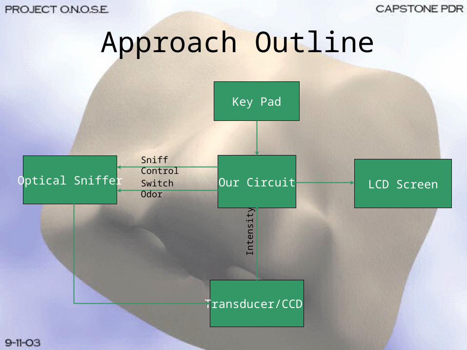
Approach Outline
Key Pad
Our CircuitOptical Sniffer
Transducer/CCD
LCD Screen
Sniff Control
Switch Odor
Inte
nsity
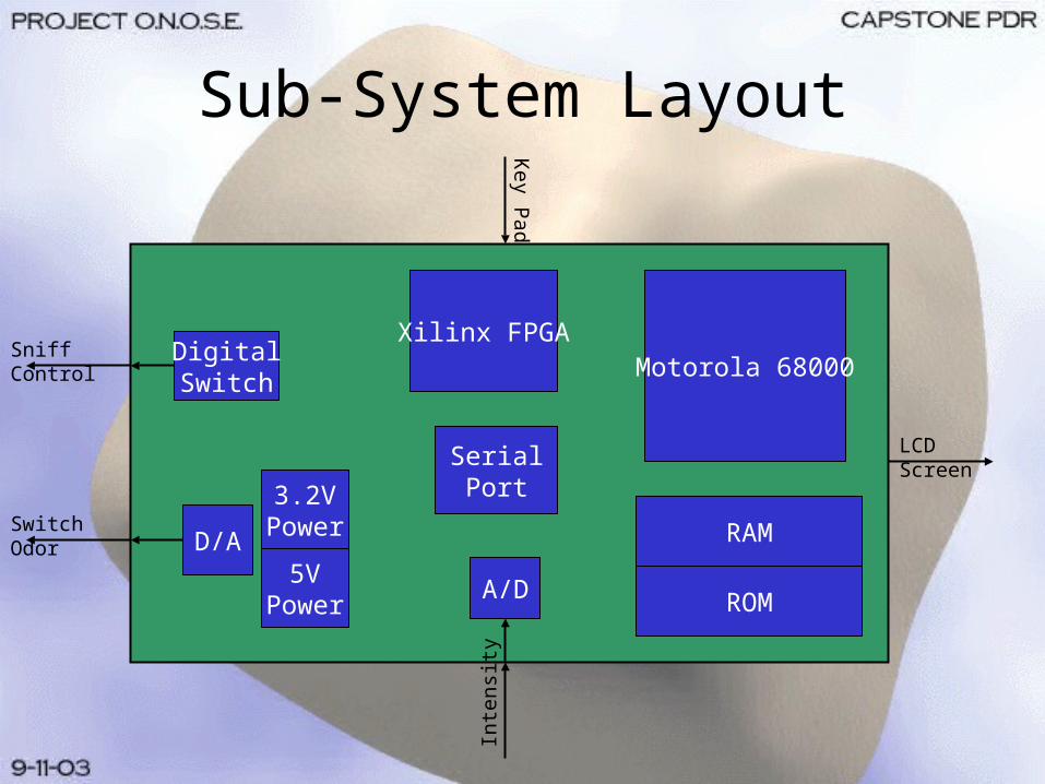
Sub-System Layout
Motorola 68000Xilinx FPGA
A/D
Inte
nsity
Switch Odor
Sniff Control
Key P
ad
LCD Screen
D/A RAM
ROM
DigitalSwitch
3.2VPower
5VPower
SerialPort

ScheduleEvents September October November December
PDR PDR
design
bui ld i t
CDR CDR
Connect i t
Feedback
I Milestone I
battery
LCD
Input
I I Milestone I I
Technical Referance Manual
Expo Expo
User 's Manual

Events September October November December
PDR PDR
design
bui ld i t
CDR CDR
Connect i t
Feedback
I Milestone I
battery
LCD
Input
I I Milestone I I
Technical Referance Manual
Expo Expo
User 's Manual
Risks and Contingency Plan
Risk 1: Design•Customer wants vs. needs•Size vs. performance
Risk 2: Connect it•Assumptions•User friendly vs. connecting
X1X
XX2XX

Events September October November December
PDR PDR
design
bui ld i t
CDR CDR
Connect i t
Feedback
I Milestone I
battery
LCD
Input
I I Milestone I I
Technical Referance Manual
Expo Expo
User 's Manual
More Risks
Risk 4: Battery Power•Battery vs. outlet
X4X
X3XRisk 3: Feedback•Known PPM

Future Upgrades
• Wireless Link– Makes use of a one way transmitter and
receiver to send output data to a remote location
• Rover Mount– Would allow the O.N.O.S.E. to be mounted on
a RC rover, to send the system into possible hazardous locations and get the readout remotely
Future Upgrades Continued
• Capability to detect multiple scents– Exchanging single polymer ‘disks’– Implementing multiple polymer arrays on a
single disk

EconomicsComponent Estimated Cost
Processor $10.00
FPGA $30.00
A/D, D/A $20.00
LCD $10.00
Wirewrap Board $40.00
Wires/caps/resistors $5.00
Power Supply $5.00
Power Converters $5.00
Serial Port $5.00
Digital Switch $2.00
RAM/ROM $10.00
Miscellaneous $20.00
Total: $162.00

ROI/Impact on Society
• Due to the numerous applications and uniqueness of the system, there is a large market share.
• Assuming one could be sold for $200.00, the ROI would be at least 50%.
• Society benefits from the possible increase in security, health benefits, and environmental safety.
Sustainability
• The processor unit is very sustainable– Parts are inexpensive and widely available.
• The optical unit is more delicate and may require more expertise to maintain.– Optic system requires precise adjustment.– Laser and lenses are more expensive.– Transducers must be custom made.

Questions?
• Jennifer Sweezey– Project Introduction
– Proposed Objective
• Andy White– Existing Hardware
• Chris Bauer– Approach outline
– Sub-systems
• Diane Cyr– Schedule
– Risks & contingencies
• Anubhav Bhatia– Upgrades
– Economics