Embed Size (px)
Citation preview

Project Overview
Ron StrykowskyProject Manager for Construction Project
Princeton Plasma Physics Laboratory
Readiness for Operations Review
LSB B318December 9-11, 2014
NSTX-UNSTX-U Supported by
Culham Sci CtrYork U
Chubu UFukui U
Hiroshima UHyogo UKyoto U
Kyushu UKyushu Tokai U
NIFSNiigata UU Tokyo
JAEAInst for Nucl Res, Kiev
Ioffe InstTRINITI
Chonbuk Natl UNFRI
KAISTPOSTECH
Seoul Natl UASIPP
CIEMATFOM Inst DIFFER
ENEA, FrascatiCEA, Cadarache
IPP, JülichIPP, Garching
ASCR, Czech Rep
Coll of Wm & MaryColumbia UCompXGeneral AtomicsFIUINLJohns Hopkins ULANLLLNLLodestarMITLehigh UNova PhotonicsOld DominionORNLPPPLPrinceton UPurdue USNLThink Tank, Inc.UC DavisUC IrvineUCLAUCSDU ColoradoU IllinoisU MarylandU RochesterU TennesseeU TulsaU WashingtonU WisconsinX Science LLC

Content
• Scope
• Execution Plan
• Deliverables
• Summary
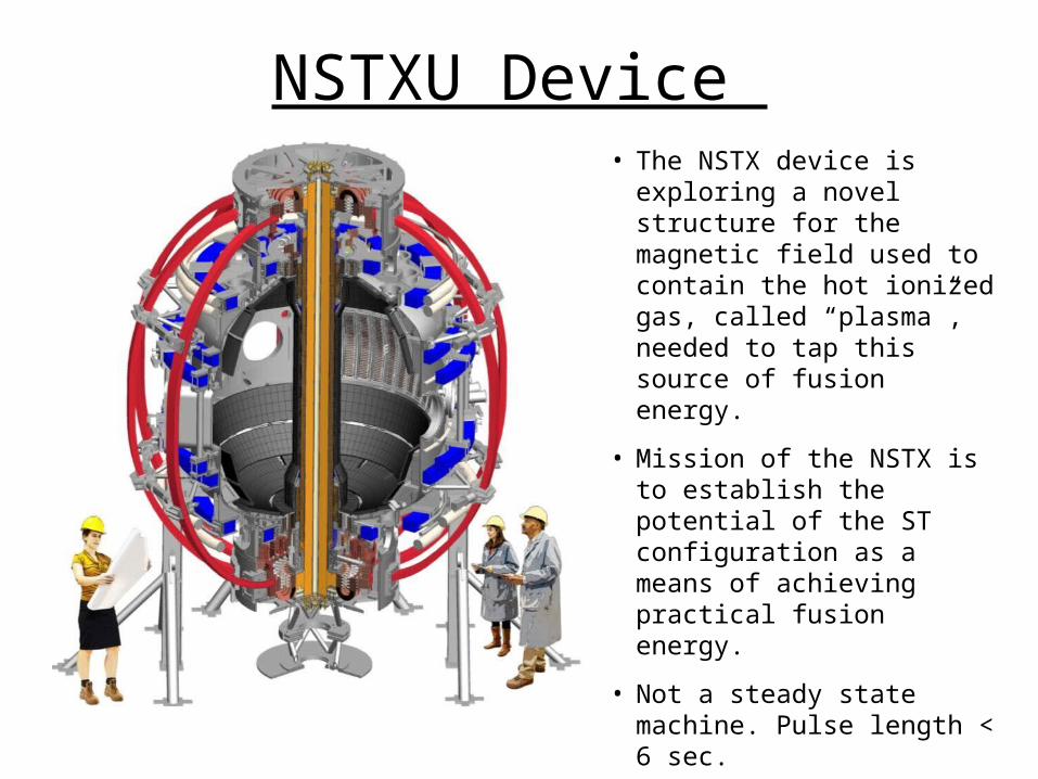
NSTXU Device • The NSTX device is exploring a
novel structure for the magnetic field used to contain the hot ionized gas, called “plasma”, needed to tap this source of fusion energy.
• Mission of the NSTX is to establish the potential of the ST configuration as a means of achieving practical fusion energy.
• Not a steady state machine. Pulse length < 6 sec.
• Design rep rate <40 minute

Technical Performance Baseline Parameters (defined in section 2.2.1 of the Project Execution Plan (PEP))
Technical Performance Baseline Parameters
To meet the mission need objective, the existing NSTX machine at PPPL will be upgraded to permit operation at the following increased levels;
• Toroidal field from 0.5 tesla to 1.0 tesla;• Pulse length from ~1.0 second to 5.0 seconds;• Plasma current from 1MA to 2MA;• Neutral beam heating from 5-7MW to 10-14MW
‒ Design basis‒ Day 1 hardware capable (design and tested)‒ Not Day 1 planned achievement (phased in during 2-3 years)
‒ Design basis‒ Day 1 hardware capable (design and tested)‒ Not Day 1 planned achievement (phased in during 2-3 years)

NSTX Upgrade Deliverables1) Double field and current
Center Stack (CS) Upgrade. –Design, build and install new CS assembly including;– a new toroidal field (TF) hub assembly, –new TF flag assemblies, –new ceramic break, –new inner TF bundle, –new ohmic heating coil, –new plasma facing component (PFC) tiles,–new poloidal field (PF) 1a, b & c coils.–Power, controls, water, services
2) Double neutral beam power & more tangential injection2nd Neutral Beam-line (NBL).
• Decontaminate and prepare a TFTR neutral beam-line (NBL) for installation on NSTX.
• Evaluate and refurbish internal components as necessary (cryogenic panels, beam dumps, bending magnets, beam scrapers, calorimeter, etc.).
• Relocate the NBL and • Provide a second set of beam-line services (e.g., power, water, vacuum,
cryogenics, etc.).
This represents a major modification to an existing fusion deviceThis represents a major modification to an existing fusion device
Larry Dudek will discuss in detail
Larry Dudek will discuss in detail
Tim Stevenson to discuss in detail
Tim Stevenson to discuss in detail

CD-4 milestone completion criteria defined in section 2.2.2 of the Project Execution Plan
(PEP)2.2.2.2 Demonstrated Performance 1.The major milestone marking the transition from a fabrication project to an operating facility is the first plasma milestone (CD-4). First plasma is defined as an ohmically heated discharge > 50 kA at a toroidal magnetic field of > 1 kG. The operations phase will resume upon completion of the first plasma milestone.2.The installation of the second neutral beam on NSTX shall be considered complete at the stage where each item below has been demonstrated:a.Beamline water, vacuum, cryogenics, and feedstock gas services have been attached to the beamline;b.A Torus Isolation Valve and duct interconnects the NSTX vacuum vessel and the neutral beamline;c.Local Control Centers have been powered on to monitor power supply status, and;d.Project will be verified as complete when a 40,000 electron-volt beam has been produced and injected into the armor for .050 seconds

Project Organized to Execute Mission
Most staff will transition over to machine operations
Most staff will transition over to machine operations
NSTX Physics LiaisonStefan Gerhrdt
NSTX Operations LiaisonAl vonHalle
PPPL QA/QCJudy Malsbury
PPPL ES&HJerry Levine
PPPL ProcurementWray Myers
Sources & ControlsM. Cropper
NB Relocation/ ServicesN. Atnafu
NBI ArmorK. Tresemer
NBI PowerR. Ramakrishnan
NTC EquipmentRelocation
E. Perry
Control Sys Data Acquisition
P.Sichta
Auxiliary SystemsW. Blanchard
ConstructionE.Perry
Integrated Systems Testing/Startup
C.Gentile
Centerstack Design & Procurement
S.Raftopoulos
NSTX Upgrade Project ManagerR. Strykowsky
Deputy and Construction ManagerE. Perry
Project ControlsS. Langish
NSTX Centerstack ManagerL. Dudek
NSTX Neutral Beam Manager
T. StevensonEngineering Support
Sys Analysis: P. TitusSys Integr: C. Neumeyer
Associate DirectorM. Williams
Structures & SupportsM. Smith
Electrical SystemsR. Ramakrishnan
DiagnosticsR.Kaita
Centerstack PFCK. Tresemer
VPS/NB/TVPS DuctW. Blanchard

Project Scope WBS BreakdownCONTROL ACCOUNT PLAN SPREADSHEET
JOB NO RLM TITLECONTROL ACCT MGR
Pct Complete
1000 CSU Analytical Support Pete Titus 100%1001 CS Plasma Facing Components Kelsey Tresemer 100%1002 Passive Plate Analysis & Upgrade Act Neway Atnafu 100%1200 Vacuum Vessel & Structural Supports Mark Smith 100%1300 Center Stack Upgrade Project Design Support Steve Raftopoulos 100%1301 Outer Toroidal Field Coils (incl 1300 CAD sprt) Steve Raftopoulos 100%1302 Center Stack Assembly Steve Raftopoulos 94%1303 TF Joint Test Stand & Perform Test Steve Raftopoulos 100%1304 Inner TF Bundle (Dsgn/Fab) Steve Raftopoulos 100%1305 OHMIC Heating Coil (OH) DSGN/FAB Steve Raftopoulos 100%1306 Inner Poloidal Field Coils (Shaping) Steve Raftopoulos 100%1307 CS Casing Assembly (DSGN/FAB) Steve Raftopoulos 100%1310 CS Design General (DSGN/FAB) Steve Raftopoulos 100%2300 ECH Analysis Pete Titus 100%2420 2nd NBI Sources Mark Cropper 100%2425 BL Relocation Neway Atnafu 100%2430 2nd NBI Decontamination Tim Stevenson 100%2440 2nd NBI Beamline Mark Cropper 100%2450 2nd NBI Services Mark Cropper 95%2460 2nd NBI Armor Kelsey Tresemer 100%2470 2nd NBI Power Raki Ramakrishnan 100%2475 2nd NBI Controls Mark Cropper 82%2480 2nd NBI/TVPS Duct Bill Blanchard 100%2485 Vacuum Pumping System Bill Blanchard 100%2490 NTC Equipt Relocations Erik Perry 95%
Larry Dudek
Tim Stevenson
Larry Dudek will discuss
scope in detail
Larry Dudek will discuss
scope in detail
Tim Stevenson to discuss
scope in detail
Tim Stevenson to discuss
scope in detail
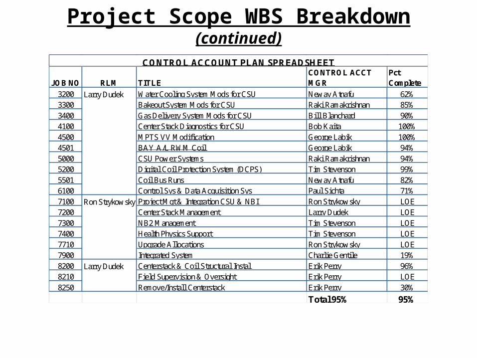
Project Scope WBS Breakdown (continued)
CONTROL ACCOUNT PLAN SPREADSHEET
JOB NO RLM TITLECONTROL ACCT MGR
Pct Complete
3200 Water Cooling System Mods for CSU Neway Atnafu 62%3300 Bakeout System Mods for CSU Raki Ramakrishnan 85%3400 Gas Delivery System Mods for CSU Bill Blanchard 90%4100 Center Stack Diagnostics for CSU Bob Kaita 100%4500 MPTS VV Modification George Labik 100%4501 BAY A/L RWM Coil George Labik 94%5000 CSU Power Systems Raki Ramakrishnan 94%5200 Digital Coil Protection System (DCPS) Tim Stevenson 99%5501 Coil Bus Runs Neway Atnafu 82%6100 Control Sys & Data Acquisition Sys Paul Sichta 71%7100 Project Mgt & Integration CSU & NBI Ron Strykowsky LOE7200 Center Stack Management Larry Dudek LOE7300 NB2 Management Tim Stevenson LOE7400 Health Physics Support Tim Stevenson LOE7710 Upgrade Allocations Ron Strykowsky LOE7900 Integrated System Charlie Gentile 19%8200 Centerstack & Coil Structural Instal Erik Perry 96%8210 Field Supervision & Oversight Erik Perry LOE8250 Remove/Install Centerstack Erik Perry 30%
Total 95% 95%
Larry Dudek
Ron Strykowsky
Larry Dudek
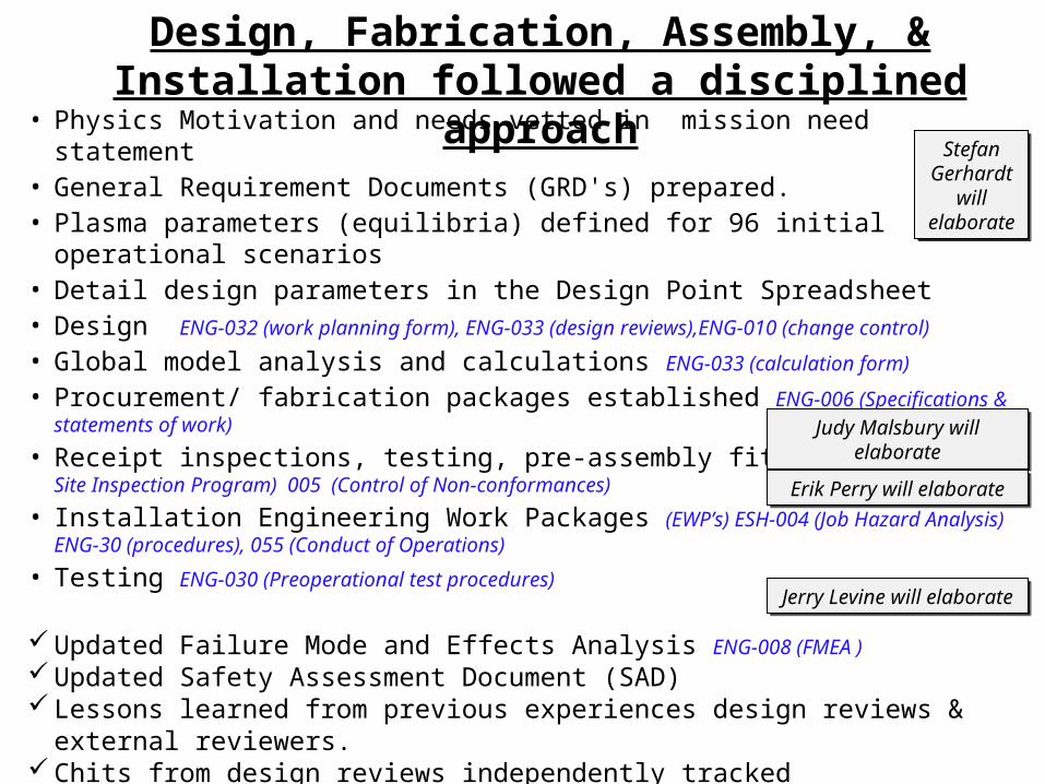
• Physics Motivation and needs vetted in mission need statement• General Requirement Documents (GRD's) prepared. • Plasma parameters (equilibria) defined for 96 initial operational scenarios• Detail design parameters in the Design Point Spreadsheet• Design ENG-032 (work planning form), ENG-033 (design reviews),ENG-010 (change control)
• Global model analysis and calculations ENG-033 (calculation form)
• Procurement/ fabrication packages established ENG-006 (Specifications & statements of work)
• Receipt inspections, testing, pre-assembly fit-ups QA-004 (PPPL Site Inspection Program) 005 (Control of Non-conformances)
• Installation Engineering Work Packages (EWP’s) ESH-004 (Job Hazard Analysis) ENG-30 (procedures), 055 (Conduct of Operations)
• Testing ENG-030 (Preoperational test procedures)
Updated Failure Mode and Effects Analysis ENG-008 (FMEA ) Updated Safety Assessment Document (SAD) Lessons learned from previous experiences design reviews & external reviewers. Chits from design reviews independently tracked Risk registry maintained that identified mitigation plans that were incorporated into
the design where applicable
Design, Fabrication, Assembly, & Installation followed a disciplined approach
Judy Malsbury will elaborate
Judy Malsbury will elaborate
Jerry Levine will elaborateJerry Levine will elaborate
Erik Perry will elaborateErik Perry will elaborate
Stefan Gerhardt
will elaborate
Stefan Gerhardt
will elaborate

NSTXU Design, Fabrication and Assembly vetted by a rigorous review process
• Multiple design & project level reviews (per eng-033).
• Chits documented and independently tracked by QA (402 total 94% closed). Remaining 6% to be closed prior to startup. Will be confirmed by the Activity Certification Committee (ACC).
• 69 individual external reviewers from 22 institutions
• QA integral part of the design, procurement, fabrication, and inspection process.
Judy Malsbury will describe
QA/QC oversight.
Judy Malsbury will describe
QA/QC oversight.
Charlie Gentile will discuss the ACC process
Charlie Gentile will discuss the ACC process

Major Machine Components Description
Larry Dudek will discuss center stack and machine
scope in detail
Larry Dudek will discuss center stack and machine
scope in detail
New NB portOuter TF coils
PF Coils

Center Stack - Core of machine
Improved Joint Design
Reinforced Coil Supports
Simpler Inner TF design(single layer of TF conductors)
OH coil wound on TF
Existing outer TF WITH water cooling
Much R&D was required to vet critical design detailsMuch R&D was required to vet critical design details

Centerstack Upgrade ScopeBolted joints located at
further radius hence lower joint current density and lower magnetic field at joint
Two conductors types and two layers
TF Bundle contains 36 identical conductors with one-layer joint
design with non zinc-chloride flux
Original CS
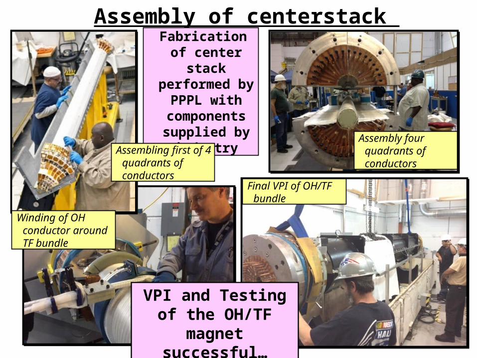
Assembly of centerstack Fabrication of
center stack performed by
PPPL with components supplied by
industryAssembling first of 4
quadrants of conductors
Assembly four quadrants of conductors
Winding of OH conductor around TF bundle
Final VPI of OH/TF bundle
VPI and Testing of the OH/TF magnet
successful…however

OH Aquapour Removal Issue 100 mill Aquapour gap
TFCoil
OH Coil
• During VPI, epoxy saturated the Aquapour turning it into waster resistant substance.
• No solution for removing the remaining Aquapour- epoxy mixed material. Decision to leave Aquapour in place.
• Independent peer review conducted to determine mitigation plan.
• Minimal impact on Operations Stefan Gerhardt will discuss operations
considerations in detail
Stefan Gerhardt will discuss operations
considerations in detail

Final sanding and clear coat applied.Final sanding and clear coat applied.
Outer ground plane applied.
Outer ground plane applied.
OH/TF center stack bundle assembly completed
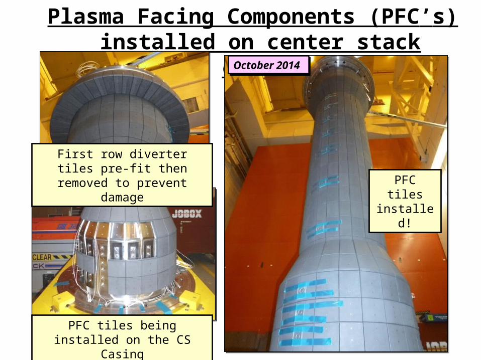
PFC tiles being installed on the CS Casing
Plasma Facing Components (PFC’s) installed on center stack casing
PFC tiles installed!
First row diverter tiles pre-fit then removed to prevent damage
October 2014October 2014

Casing with tiles installed over the OH/TF bundle

Center stack assembly installed into the NSTX Machine

Second Neutral Beam Scope
NSTX test cell TFTR test cell
A TFTR Neutral Beamline was Decontaminated and relocated to the NSTX Test Cell
Tim Stevenson will discuss Neutral Beam
scope in detail
Tim Stevenson will discuss Neutral Beam
scope in detail

NBL2 Duct w/ new TIV
Torus Vessel Pump System Duct
Port Extension
Bay J-K Cap
(Required NSTX Vessel Modification)
NBI Armor addition
Second Neutral Beam - Scope (continued)

Second Neutral Beam Relocated
23
• Beam box = 40 tons• Lid = 14 tons
• Began work February 2009• 30,000 hours (>17 person years) for
decontamination, refurbishment, relocation design

Neutral beam component installation
Neutral Beam & TIV valve
Neutral Beam & TIV valve
• Neutral Beam connecting duct assembly being lowered into position
• Neutral Beam connecting duct assembly being lowered into position
Vacuum Vessel Bay J/K rectangular port
Vacuum Vessel Bay J/K rectangular port
Turbo molecular vacuum Pumps
Turbo molecular vacuum Pumps
Round bellows and duct
Round bellows and duct
Rectangular Bellows
Rectangular Bellows
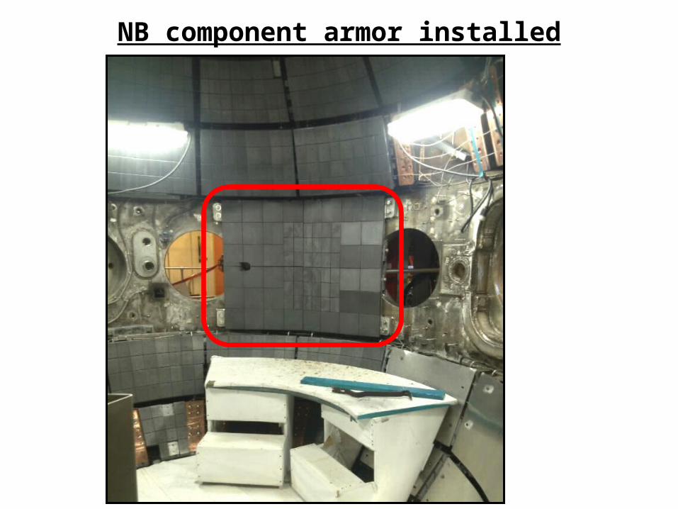
NB component armor installed

Neutral Beam High Voltage Enclosures & Transmission Lines Installed
Construction Coordination
• Use of a Work Control Center for all work in the test cell. Project in-charge during assembly and testing (Erik Perry). Handoff to Operations (Al vonHalle) for start of ISTP
• System pre-operational tests conducted as part of the WBS scope.
• Work Control Center reviews all Engineering Work Packages for the field
• Daily Plan-of-the-Day meetings to coordinate activities between crews and fine tune technician assignments
Erik Perry to discuss in detail
Erik Perry to discuss in detail

Current machine status
High Voltage Enclosures (HVE)
High Voltage Enclosures (HVE)
Neutral Beam Duct/TVPSNeutral Beam Duct/TVPS New
PlatformsNew Platforms
Neutral Beam (NB) #1
Neutral Beam (NB) #1
Neutral Beam (NB) #2
Neutral Beam (NB) #2
New CenterstackNew Centerstack
Machine Ready for pump downMachine Ready for pump down
Existing RF pipesExisting RF pipes
NB #1 duct in place.NB #1 duct in place.

Summary
• Technical Performance Baseline Parameters as documented in the PEP and GRD’s were the basis for the project design.
• Execution of project scope followed a disciplined and auditable process following mature PPPL Procedures.
• Startup of NSTX (OP-NSTX-02) and start of ISTP (OP-NSTX –
ISTP-01) marks the turnover from construction to operations.
• Conclusion of the construction project will be achieved as defined in the PEP Demonstrated Performance.
• Construction is almost complete. We will be ready to operate

Backup slides

Analysis & Value Engineering – An Iterative process
TF Inner Leg and Flex Joint Qualification • Concept, Initial Analysis• TF Inner Joint Stress, Contact Pressures • TF Current Diffusion • TF Torsional Shear • TF Stress, Insulation Tension Stress • TF Tooth Interface w/Umbrella Structure
Outer TF Leg Analysis • Torsional OOP Loads • Stress, Insulation Tension Stress • Outer Leg Support
Vessel and Umbrella Structure Original, Early Upgrade Full 360 degree Model from Pro E,
Reinforcements TF Loading on Alum Blocks, hang, Vessel Lid and Bottom Cover Connection,
Central Column to Umbrella Vacuum loading with neutral beam ports
Disruption • OPERA Axisymmetric• Vessel and Passive Plates, Early Upgraded
Loads +DLF• Detailed Vessel and Passive Plates• EMAG Transient Dynamic Analysis• Center Stack Casing with Halo Currents
Other• Center Stack • Plasma Facing Components• Inner PF Supports • Outer PF Supports • Lower Support Pedestal • HHFW Antenna Analyses
96 Plasma Equilibria (Physics) 96 Plasma Equilibria (Physics) Design Point SS (Magnetic loads) Design Point SS (Magnetic loads)
Analysis (ANSYS, Workbench) Analysis (ANSYS, Workbench)
Design (CAD Models) Design (CAD Models)
Field Assembly (Field Experience)Field Assembly (Field Experience)
•Pushing the structural limits of the existing machine required significant analytical modeling in concert with Physics, engineering and field input to optimize the design.•Additional inspections and instrumentation requirements added (Larry Dudek, Steve Raftopoulos to discuss)
•Pushing the structural limits of the existing machine required significant analytical modeling in concert with Physics, engineering and field input to optimize the design.•Additional inspections and instrumentation requirements added (Larry Dudek, Steve Raftopoulos to discuss)

NSTXU Test Cell
Mockup Bldg
Tunnel from NSTXU
control room to D-Site
Neutral Beam Power
Conversion Bldg
Magnet Power Rectifiers
Motor Generators
NSTXU Control Room
(basement level)
RF Transmission lines
Field Coil Power Conversion Bldg
RF Bldg
Centerstack Fabrication
areaD-Site
C-Site
138kV electric
transmission line to PPPL
You are here
Princeton Plasma Physics Laboratory-NSTXU

Requirements documented in 2 GRD’sNSTX CENTER STACK UPGRADE
GENERAL REQUIREMENTS DOCUMENTNSTX_CSU-RQMTS-GRD
Revision 5June 14, 2012
This General Requirements Document (GRD) defines:•The Machine Parameters (Table 1-1)•The overall engineering requirements for the Center Stack Upgrade as well those specific to each major element of the Work Breakdown Structure (WBS) (Table 1-2)•The Machine Planned Pulse duty (Table 2-4)•Performance and plasma shape including disruption modes

Design Point Spreadsheets• Physics • Radial Build • Center Stack Dimensions • TF Coil • OH Coil • Inner PF Coils • PF/OH Coil Summary • Power Systems • Coil Circuit Summary • Coil Insulation Summary • PF/OH Coil Forces • Coil Combination Forces and Moments • PFC Heat Loads • TF Current Waveform • Force Influence Matricies • Circuit Impedances • Pulse Spectrum • Design Point Spreadsheets
Provides detail design parameters that need to be met to satisfy the GRD and 96 plasma equilibria.
NSTX BASE NSTX CSUOH R inside tension tube m 0.1037 0.2030dRtension tube m 0.0040 0.0000Teflon Slip Plane m 0.0002 0.0002OH Ground Plane (inner) thickness m 0 0.0002OH Ground insulation (inner) m 0.0008 0.0027OH Turn insulation m 0.0007 0.0012OH Ground & turn insulation (inner) m 0.0015 0.0040OH Rcuinner m 0.1094 0.2074OH Rcuouter m 0.1548 0.2768OH Ground insulation (outer) m 0.0008 0.0027OH Ground & turn insulation (outer) m 0.0015 0.0040OH Ground Plane (outer) thickness m 0.0000 0.0002OH dZcu m 4.2416 4.2605OH #turns turns 964 888OH #layers layers 4 4OH Conductor width m 0.0103 0.0155OH Conductor height m 0.0162 0.0168OH Cooling hole diameter m 0.0048 0.0057OH Conductor corner radius m 0.0010 0.0010OH Packing fraction 0.7455 0.7012OH Voltage Volt 6077 6077OH Current Base Amp 24000 24000OH Tesw (L/R decay) s 0.428 1.472OH Action (L/R decay) A 2̂-s 2.47E+08 8.48E+08OH Turn-Turn voltage stress factor 0.50 0.50OH Turn-Turn voltage stress max kV/mm 2 1OH Voltage stress max turn-ground (inner) kV/mm 5 2OH Voltage stress max turn-ground (outer) kV/mm 5.4 2.0OH Hipot Voltage Volt 17154 17154OH Voltage stress max turn-ground (inner) (hipot) kV/mm 10.1 4.1OH Voltage stress max turn-ground (outer) (hipot) kV/mm 11.4 4.3OH Inlet Coolant Temp C 12 12OH Maximum temp (L/R decay) C 72 100OH Copper Mass Tonne 1.1 2.8
NSTX BASE NSTX CSUOH R inside tension tube in 4.0827 7.9940dRtension tube in 0.1580 0.0000Teflon Slip Plane in 0.0080 0.0080OH Ground Plane (inner) thickness in 0.0000 0.00787402OH Ground insulation (inner) in 0.0324 0.1080OH Turn insulation in 0.0268 0.0480OH Ground & turn insulation (inner) in 0.0592 0.1560OH Rcuinner in 4.3079 8.1659OH Rcuouter in 6.0928 10.8958OH Ground insulation (outer) in 0.0324 0.1080OH Ground & turn insulation (outer) in 0.0592 0.1560OH Ground Plane (outer) thickness in 0.0000 0.0079OH dZcu in 166.9921 167.7360OH #turns turns 964 888OH #layers layers 4 4OH Conductor width in 0.4060 0.6105OH Conductor height in 0.6393 0.6596OH Cooling hole diameter in 0.1880 0.2250OH Conductor corner radius in 0.0390 0.0390OH Packing fraction 0.7455 0.7012OH Voltage Volt 6077 6077OH Current Base Amp 24000 24000OH Tesw (L/R decay) s 0.428 1.472OH Action (L/R decay) A 2̂-s 2.47E+08 8.48E+08OH Turn-Turn voltage stress factor 0.50 0.50OH Turn-Turn voltage stress max Volt/mil 57 32OH Voltage stress max turn-ground (inner) Volt/mil 120 49OH Voltage stress max turn-ground (outer) Volt/mil 136.4 51.8OH Hipot Voltage Volt 17154 17154OH Voltage stress max turn-ground (inner) (hipot) Volt/mil 255.3 104.6OH Voltage stress max turn-ground (outer) (hipot) Volt/mil 289.8 110.0OH Inlet Coolant Temp C 12 12OH Maximum temp (L/R decay) C 72 100OH Copper Mass lbs 2345 6211.3
Example for OH Coil
Larry Dudek to discuss in detailLarry Dudek to discuss in detail
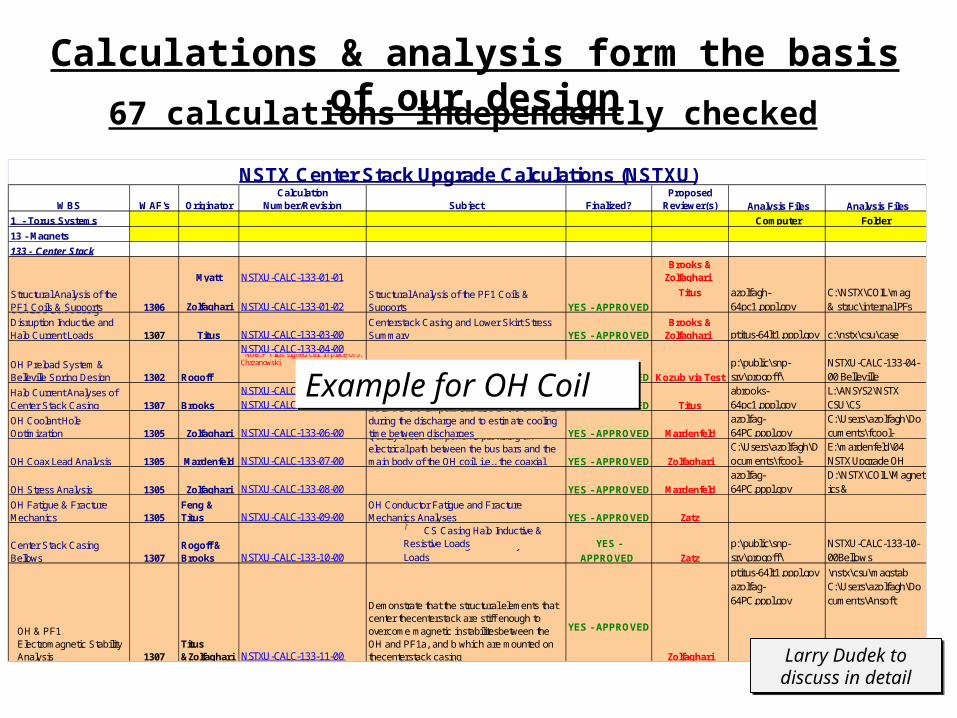
Calculations & analysis form the basis of our design
67 calculations independently checked
NSTX Center Stack Upgrade Calculations (NSTXU)
WBS WAF's OriginatorCalculation
Number/Revision Subject Finalized?Proposed
Reviewer(s) Analysis Files Analysis Files
1 - Torus Systems Computer Folder
13 - Magnets
133 - Center Stack
Myatt NSTXU-CALC-133-01-01Brooks &
Zolfaghari
Titus
Zolfaghari NSTXU-CALC-133-01-02
NSTXU-CALC-133-04-00* Note: P Titus signed calc in place of J . Chrzanowski
NSTXU-CALC-133-05-00 NSTXU-CALC-133-05-01
CS Casing Halo Inductive & Resistive Loads CS Casing Static & Dynamic Loads
ptitus-64lt1.pppl.gov \nstx\csu\magstabazolfag-64PC.pppl.gov
C:\Users\azolfagh\Documents\Ansoft
YES - APPROVEDOH & PF1 Electromagnetic Stability Analysis 1307
Titus &Zolfaghari NSTXU-CALC-133-11-00
Demonstrate that the structural elements that center thecenterstack are stiff enough to overcome magnetic instabilitesbetween the OH and PF1a, and b which are mounted on thecenterstack casing Zolfaghari
Center Stack Casing Bellows 1307
Rogoff & Brooks NSTXU-CALC-133-10-00
YES -
APPROVED Zatz
p:\public\snp-srv\progoff\
NSTXU-CALC-133-10-00Bellows
D:\NSTX\COIL\Magnetics &
OH Fatigue & Fracture Mechanics 1305
Feng & Titus NSTXU-CALC-133-09-00
OH Conductor Fatigue and Fracture Mechanics Analyses YES - APPROVED Zatz
E:\mardenfeld\04 NSTX Upgrade OH
OH Stress Analysis 1305 Zolfaghari NSTXU-CALC-133-08-00 YES - APPROVED Mardenfeld
azolfag-64PC.pppl.gov
C:\Users\azolfagh\Documents\fcool-
OH Coax Lead Analysis 1305 Mardenfeld NSTXU-CALC-133-07-00
Qualify those components providing an electrical path between the bus bars and the main body of the OH coil, i.e., the coaxial YES - APPROVED Zolfaghari
C:\Users\azolfagh\Documents\fcool-
L:\ANSYS2\NSTX CSU\CS
OH Coolant Hole Optimization 1305 Zolfaghari NSTXU-CALC-133-06-00
Estimate the temperature rise in the OH coil during the discharge and to estimate cooling time between discharges YES - APPROVED Mardenfeld
azolfag-64PC.pppl.gov
p:\public\snp-srv\progoff\
NSTXU-CALC-133-04-00 Belleville
Halo Current Analyses of Center Stack Casing 1307 Brooks
Calculate the transient halo current distribution in the CS YES - APPROVED Titus
abrooks-64pc1.pppl.gov
ptitus-64lt1.pppl.gov c:\nstx\csu\case
OH Preload System & Belleville Spring Design 1302 Rogoff
OH Preload System and Bellville Spring Design YES - APPROVED Kozub via Test
Center Stack Casing Disruption Inductive and Halo Current Loads 1307 Titus NSTXU-CALC-133-03-00
Centerstack Casing and Lower Skirt Stress Summary YES - APPROVED
Brooks & Zolfaghari
Structural Analysis of the PF1 Coils & Supports 1306
Structural Analysis of the PF1 Coils & Supports YES - APPROVED
azolfagh-64pc1.pppl.gov
C:\NSTX\COIL\mag & struc\internal PFs
Example for OH CoilExample for OH Coil
Larry Dudek to discuss in detailLarry Dudek to discuss in detail

Extensive analysis and reinforcements required for
magnet supports and vacuum Vessel
Reinforcement of the TF outer leg support structureReinforcement of the TF outer leg support structure

Design/Build Process we followed–Concept through reality roadmap
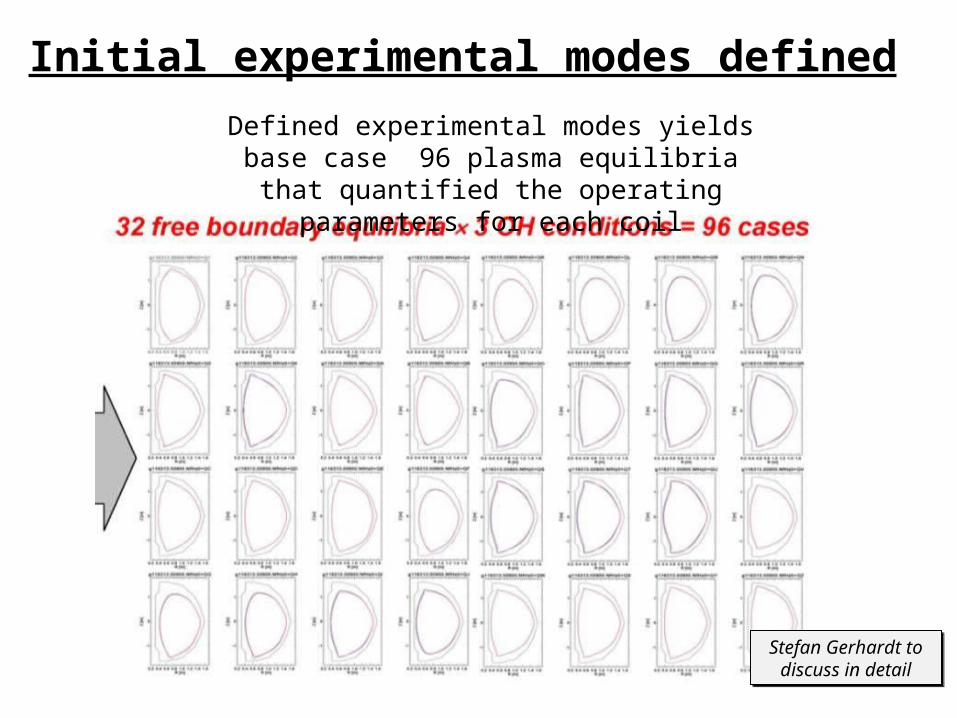
Initial experimental modes defined
Defined experimental modes yields base case 96 plasma equilibria that quantified the operating
parameters for each coil
Stefan Gerhardt to discuss in detail
Stefan Gerhardt to discuss in detail

National Spherical Torus Experiment – NSTX
NSTX Device operating since February 1999
Neutral Beam #1 operating since Sept 2000 TF Coil
PF Coil
Center-stack Assy
Plasma
Vacuum Vessel
Umbrella Structure
CS Pedestal

• Pumpdown - November
• Leak check - December
• Install bus inside umbrella and back to racks - November
• Install new TF lead extensions - January
• Install TF flex bus - January
• Install new umbrella lids - February
• Install umbrella lid support rings - February
• Bakeout - February
• ISTP - March
Remaining Construction Work in NSTX Test Cell

Work Planning Form ENG-032)
Calculation Form (ENG-033)
Engineering / Software Change Notice
(ENG-010)
Design Review Doc (ENG-033)
Chit form(ENG-033)
Procedure Cover Sheet
(ENG-030)
Procedure review and Approval Matrix
(ENG-030)
Procedure Revision Sheet
(ENG-030)
Record of Training (ENG-030)
Job Hazard Analysis (ESH-004)
Work Planning
Design Verification
Drawing/Software Control
Installation/Operations
Engineering Design Implementation

OP-NSTX-02 “Startup of NSTX” executed for each start-up(13 times)
NSTX First Plasma February 1999
NSTXU First Plasma March 2015NSTX History
1996 1997 1998 1999 2000 2001 2002 2003 2004 2005 2006 2007 2008 2009 2010 2011 2012 2013 2014 2015 2016 2017
NSTX Design &
Construction Operations
Neutral Build New NSTXU Fabrication and Beam #1 Inner TF Design Assembly
BundleRWM Coils, PF1A Upgr
Litium Evaporator
Diagnostic Upgrades = Operations
Diagnostic Upgrades
HHFW Antenna Upgrade = Outage
HHFW & Diag Upgrades
Enhanced LLD
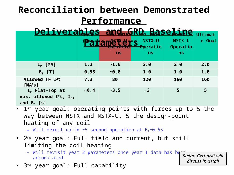
• 1st year goal: operating points with forces up to ½ the way between NSTX and NSTX-U, ½ the design-point heating of any coil
– Will permit up to ~5 second operation at BT~0.65
• 2nd year goal: Full field and current, but still limiting the coil heating– Will revisit year 2 parameters once year 1 data has been accumulated
• 3rd year goal: Full capability
NSTX(Max.)
FY 2015 NSTX-U
Operations
FY 2016 NSTX-U
Operations
FY 2017 NSTX-U
Operations
Ultimate Goal
IP [MA] 1.2 ~1.6 2.0 2.0 2.0
BT [T] 0.55 ~0.8 1.0 1.0 1.0
Allowed TF I2t [MA2s] 7.3 80 120 160 160
IP Flat-Top at max. allowed I2t, IP, and BT [s]
~0.4 ~3.5 ~3 5 5
Reconciliation between Demonstrated Performance Deliverables and GRD Baseline Parameters
Stefan Gerhardt will discuss in detail
Stefan Gerhardt will discuss in detail