Embed Size (px)
Citation preview
PROJECT REPORT FOR THE PROPOSED EXPANSION AND MODIFICATION OF
“CAUVERY SERENITY AND CAUVERY SENATE”
At
Khata No. 10/1-1, Tumkur Road, Raghavendra Extension,
Yeshwanthpur, Bangalore – 560 022..
Project Proponents M/s. Shashikiran Investments,
No. 67, “Lavina Courts”, 1st Floor, 102, 7th cross, 8th Main,
RMV Extension, Bangalore - 560 080.
Submitted to STATE LEVEL ENVIRNOMENT IMPACT
ASSESSMENT AUTHORITY (SEIAA), KARNATAKA.
ENVIRONMENTAL CONSULTANTS
M/s. AQUA TECH ENVIRO ENGINEERS, # 3391, 6th Main, 3rd Cross, RPC Layout,
Vijayanagara II Stage, Bangalore – 560 040. Tele Phone: 080 23141679
Fax: 080 23148166
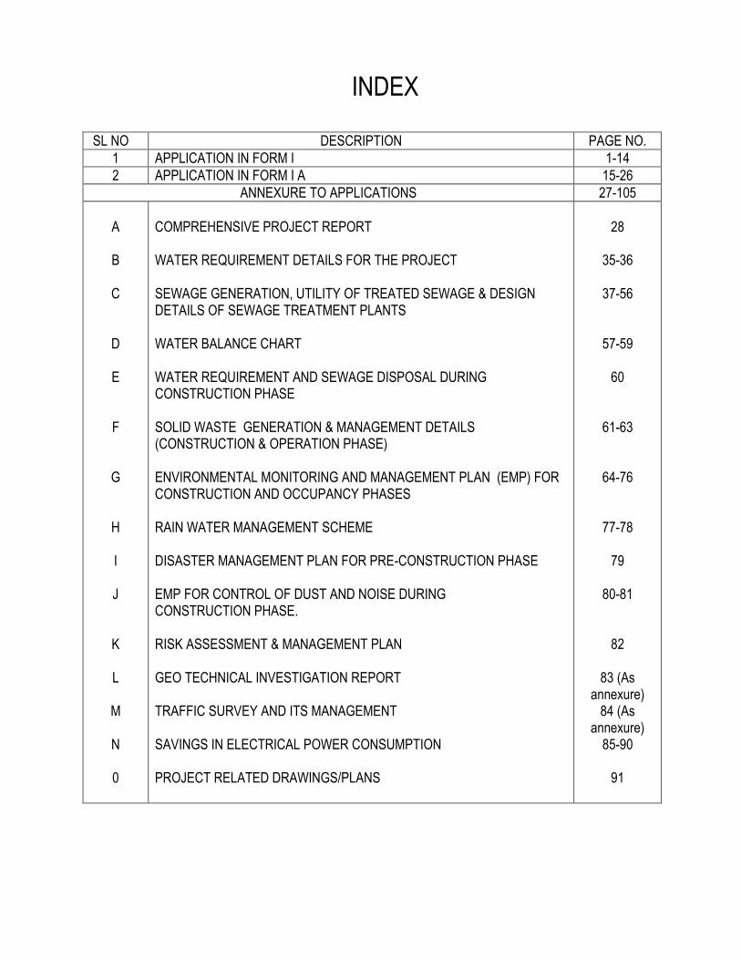
INDEX
SL NO DESCRIPTION PAGE NO.
1 APPLICATION IN FORM I 1-14
2 APPLICATION IN FORM I A 15-26
ANNEXURE TO APPLICATIONS 27-105
A
B
C
D
E
F
G
H I J
K
L
M
N
0
COMPREHENSIVE PROJECT REPORT WATER REQUIREMENT DETAILS FOR THE PROJECT SEWAGE GENERATION, UTILITY OF TREATED SEWAGE & DESIGN DETAILS OF SEWAGE TREATMENT PLANTS WATER BALANCE CHART WATER REQUIREMENT AND SEWAGE DISPOSAL DURING CONSTRUCTION PHASE SOLID WASTE GENERATION & MANAGEMENT DETAILS (CONSTRUCTION & OPERATION PHASE) ENVIRONMENTAL MONITORING AND MANAGEMENT PLAN (EMP) FOR CONSTRUCTION AND OCCUPANCY PHASES RAIN WATER MANAGEMENT SCHEME DISASTER MANAGEMENT PLAN FOR PRE-CONSTRUCTION PHASE EMP FOR CONTROL OF DUST AND NOISE DURING CONSTRUCTION PHASE. RISK ASSESSMENT & MANAGEMENT PLAN GEO TECHNICAL INVESTIGATION REPORT TRAFFIC SURVEY AND ITS MANAGEMENT SAVINGS IN ELECTRICAL POWER CONSUMPTION PROJECT RELATED DRAWINGS/PLANS
28
35-36
37-56
57-59
60
61-63
64-76
77-78
79
80-81
82
83 (As annexure)
84 (As annexure)
85-90
91
1
APPENDIX I
(See paragraph – 6)
FORM 1
(I) Basic Information
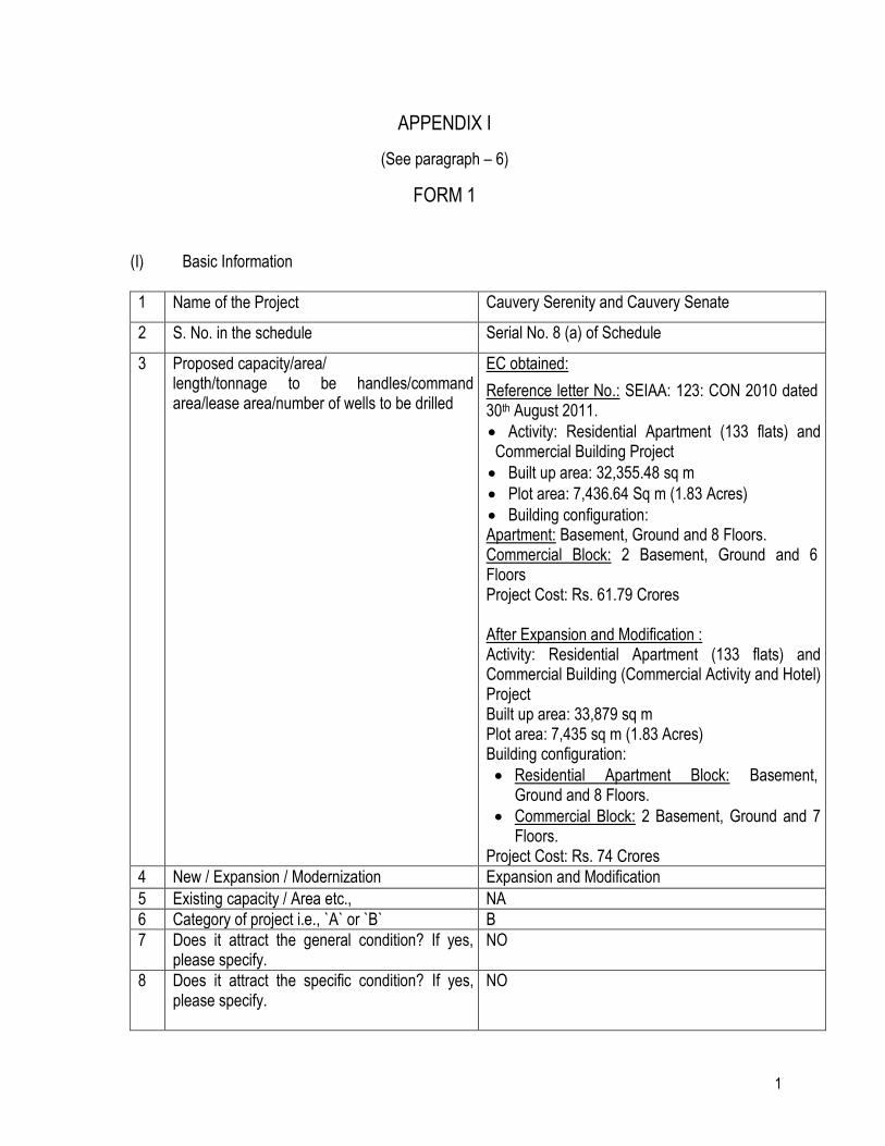
1 Name of the Project Cauvery Serenity and Cauvery Senate
2 S. No. in the schedule Serial No. 8 (a) of Schedule
3 Proposed capacity/area/ length/tonnage to be handles/command area/lease area/number of wells to be drilled
EC obtained:
Reference letter No.: SEIAA: 123: CON 2010 dated 30th August 2011.
Activity: Residential Apartment (133 flats) and Commercial Building Project
Built up area: 32,355.48 sq m
Plot area: 7,436.64 Sq m (1.83 Acres)
Building configuration: Apartment: Basement, Ground and 8 Floors. Commercial Block: 2 Basement, Ground and 6 Floors Project Cost: Rs. 61.79 Crores After Expansion and Modification : Activity: Residential Apartment (133 flats) and Commercial Building (Commercial Activity and Hotel) Project Built up area: 33,879 sq m Plot area: 7,435 sq m (1.83 Acres) Building configuration:
Residential Apartment Block: Basement, Ground and 8 Floors.
Commercial Block: 2 Basement, Ground and 7 Floors.
Project Cost: Rs. 74 Crores
4 New / Expansion / Modernization Expansion and Modification
5 Existing capacity / Area etc., NA
6 Category of project i.e., `A` or `B` B
7 Does it attract the general condition? If yes, please specify.
NO
8 Does it attract the specific condition? If yes, please specify.
NO
2
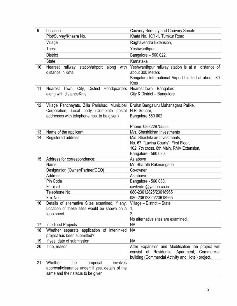
9 Location Cauvery Serenity and Cauvery Senate
Plot/Survey/Khasra No. Khata No. 10/1-1, Tumkur Road
Village Raghavendra Extension,
Thesil Yeshwanthpur,
District Bangalore – 560 022.
State Karnataka
10 Nearest railway station/airport along with distance in Kms.
Yeshwanthpur railway station is at a distance of about 300 Meters Bengaluru International Airport Limited at about 30 Kms
11 Nearest Town, City, District Headquarters along with distanceKms.
Nearest town – Bangalore City & District – Bangalore
12 Village Panchayats, Zilla Parishad, Municipal Corporation, Local body (Complete postal addresses with telephone nos. to be given)
Bruhat Bengaluru Mahanagara Palike, N.R. Square, Bangalore 560 002. Phone: 080 22975555.
13 Name of the applicant M/s. Shashikiran Investments
14 Registered address M/s. Shashikiran Investments, No. 67, “Lavina Courts”, First Floor, 102, 7th cross, 8th Main, RMV Extension, Bangalore - 560 080.
15 Address for correspondence: As above
Name Mr. Sharath Rukmangada
Designation (Owner/Partner/CEO) Co-owner
Address As above
Pin Code Bangalore - 560 080.
E – mail [email protected]
Telephone No. 080-23612825/23618965
Fax No. 080-23612825/23618965
16 Details of alternative Sites examined, if any. Location of these sites would be shown on a topo sheet.
Village – District – State 1. 2. No alternative sites are examined.
17 Interlined Projects NA
18 Whether separate application of interlinked project has been submitted?
NA
19 If yes, date of submission NA
20 If no, reason After Expansion and Modification the project will consist of Residential Apartment, Commercial building (Commercial Activity and Hotel) project.
21 Whether the proposal involves approval/clearance under: if yes, details of the same and their status to be given
3
a) The Forest (Conservation) Act 1980? b) The wildlife (Protection) Act, 1972? c) The C R Z Notification, 1991?
NO NO NO
22 Whether there is any Government Order/Policy relevant/relating to the site?
None
23 Forest land involved (Hectares) None
24 Whether there is any litigation pending against the project and/or land in which the project is propose to be set up?
a) Name of the court b) Case No. c) Orders/directions of the court, if any
and its relevance with the proposed project.
None
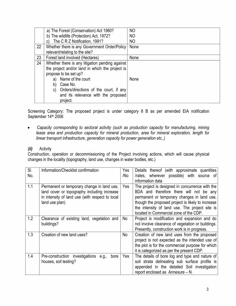
Screening Category: The proposed project is under category 8 B as per amended EIA notification September 14th 2006
Capacity corresponding to sectoral activity (such as production capacity for manufacturing, mining lease area and production capacity for mineral production, area for mineral exploration, length for linear transport infrastructure, generation capacity for power generation etc.,)
(ii) Activity Construction, operation or decommissioning of the Project involving actions, which will cause physical changes in the locality (topography, land use, changes in water bodies, etc.)
Sl. No.
Information/Checklist confirmation Yes /No
Details thereof (with approximate quantities /rates, wherever possible) with source of information data
1.1 Permanent or temporary change in land use, land cover or topography including increase in intensity of land use (with respect to local land use plan)
Yes The project is designed in concurrence with the BDA and therefore there will not be any permanent or temporary changes in land use, though the proposed project is likely to increase the intensity of land use. The project site is located in Commercial zone of the CDP.
1.2 Clearance of existing land, vegetation and buildings?
No Project is modification and expansion and do not involve clearance of vegetation or buildings. Presently, construction work is in progress.
1.3 Creation of new land uses? No Creation of new land uses from the proposed project is not expected as the intended use of the plot is for the commercial purpose for which it is categorized as per the present CDP.
1.4 Pre-construction investigations e.g., bore houses, soil testing?
Yes The details of bore log and type and nature of soil strata delineating sub surface profile is appended in the detailed Soil investigation report enclosed as Annexure – N.
4
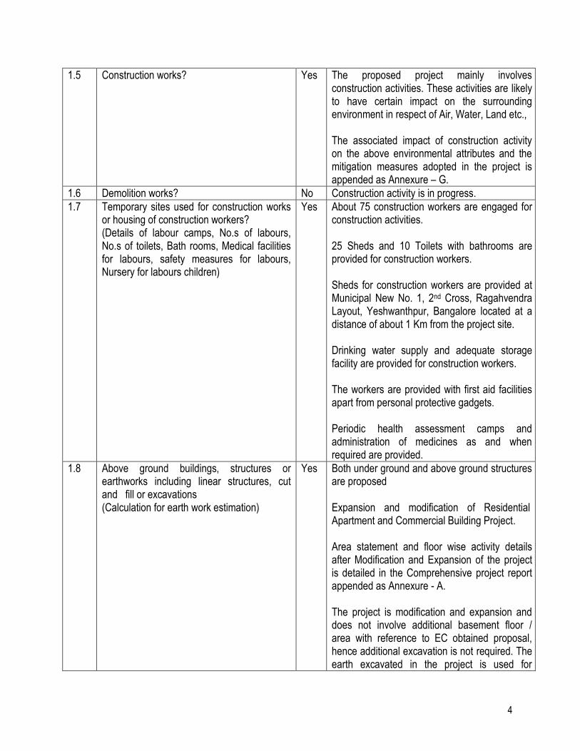
1.5 Construction works?
Yes The proposed project mainly involves construction activities. These activities are likely to have certain impact on the surrounding environment in respect of Air, Water, Land etc., The associated impact of construction activity on the above environmental attributes and the mitigation measures adopted in the project is appended as Annexure – G.
1.6 Demolition works? No Construction activity is in progress.
1.7 Temporary sites used for construction works or housing of construction workers? (Details of labour camps, No.s of labours, No.s of toilets, Bath rooms, Medical facilities for labours, safety measures for labours, Nursery for labours children)
Yes About 75 construction workers are engaged for construction activities.
25 Sheds and 10 Toilets with bathrooms are provided for construction workers. Sheds for construction workers are provided at Municipal New No. 1, 2nd Cross, Ragahvendra Layout, Yeshwanthpur, Bangalore located at a distance of about 1 Km from the project site. Drinking water supply and adequate storage facility are provided for construction workers. The workers are provided with first aid facilities apart from personal protective gadgets. Periodic health assessment camps and administration of medicines as and when required are provided.
1.8 Above ground buildings, structures or earthworks including linear structures, cut and fill or excavations (Calculation for earth work estimation)
Yes Both under ground and above ground structures are proposed Expansion and modification of Residential Apartment and Commercial Building Project. Area statement and floor wise activity details after Modification and Expansion of the project is detailed in the Comprehensive project report appended as Annexure - A. The project is modification and expansion and does not involve additional basement floor / area with reference to EC obtained proposal, hence additional excavation is not required. The earth excavated in the project is used for
5
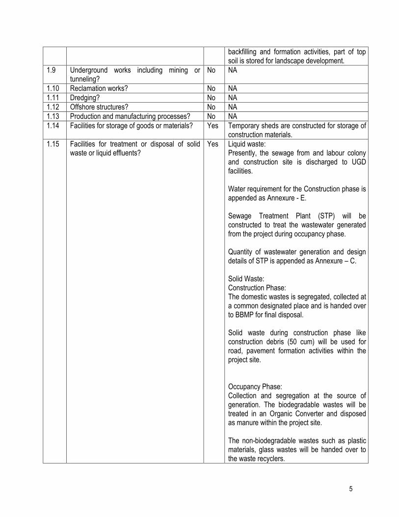
backfilling and formation activities, part of top soil is stored for landscape development.
1.9 Underground works including mining or tunneling?
No NA
1.10 Reclamation works? No NA
1.11 Dredging? No NA
1.12 Offshore structures? No NA
1.13 Production and manufacturing processes? No NA
1.14 Facilities for storage of goods or materials? Yes Temporary sheds are constructed for storage of construction materials.
1.15 Facilities for treatment or disposal of solid waste or liquid effluents?
Yes Liquid waste: Presently, the sewage from and labour colony and construction site is discharged to UGD facilities. Water requirement for the Construction phase is appended as Annexure - E. Sewage Treatment Plant (STP) will be constructed to treat the wastewater generated from the project during occupancy phase. Quantity of wastewater generation and design details of STP is appended as Annexure – C. Solid Waste: Construction Phase: The domestic wastes is segregated, collected at a common designated place and is handed over to BBMP for final disposal. Solid waste during construction phase like construction debris (50 cum) will be used for road, pavement formation activities within the project site. Occupancy Phase: Collection and segregation at the source of generation. The biodegradable wastes will be treated in an Organic Converter and disposed as manure within the project site. The non-biodegradable wastes such as plastic materials, glass wastes will be handed over to the waste recyclers.
6
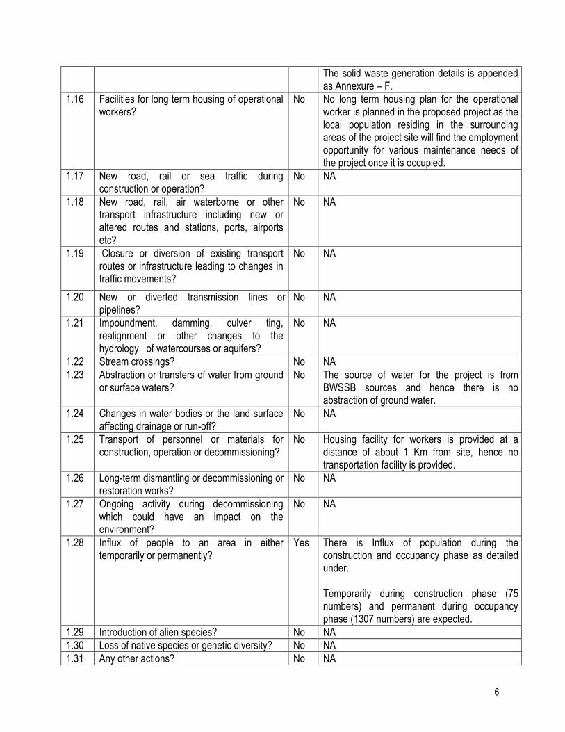
The solid waste generation details is appended as Annexure – F.
1.16 Facilities for long term housing of operational workers?
No No long term housing plan for the operational worker is planned in the proposed project as the local population residing in the surrounding areas of the project site will find the employment opportunity for various maintenance needs of the project once it is occupied.
1.17 New road, rail or sea traffic during construction or operation?
No NA
1.18 New road, rail, air waterborne or other transport infrastructure including new or altered routes and stations, ports, airports etc?
No NA
1.19 Closure or diversion of existing transport routes or infrastructure leading to changes in traffic movements?
No NA
1.20 New or diverted transmission lines or pipelines?
No NA
1.21 Impoundment, damming, culver ting, realignment or other changes to the hydrology of watercourses or aquifers?
No NA
1.22 Stream crossings? No NA
1.23 Abstraction or transfers of water from ground or surface waters?
No The source of water for the project is from BWSSB sources and hence there is no abstraction of ground water.
1.24 Changes in water bodies or the land surface affecting drainage or run-off?
No NA
1.25 Transport of personnel or materials for construction, operation or decommissioning?
No Housing facility for workers is provided at a distance of about 1 Km from site, hence no transportation facility is provided.
1.26 Long-term dismantling or decommissioning or restoration works?
No NA
1.27 Ongoing activity during decommissioning which could have an impact on the environment?
No NA
1.28 Influx of people to an area in either temporarily or permanently?
Yes There is Influx of population during the construction and occupancy phase as detailed under. Temporarily during construction phase (75 numbers) and permanent during occupancy phase (1307 numbers) are expected.
1.29 Introduction of alien species? No NA
1.30 Loss of native species or genetic diversity? No NA
1.31 Any other actions? No NA
7
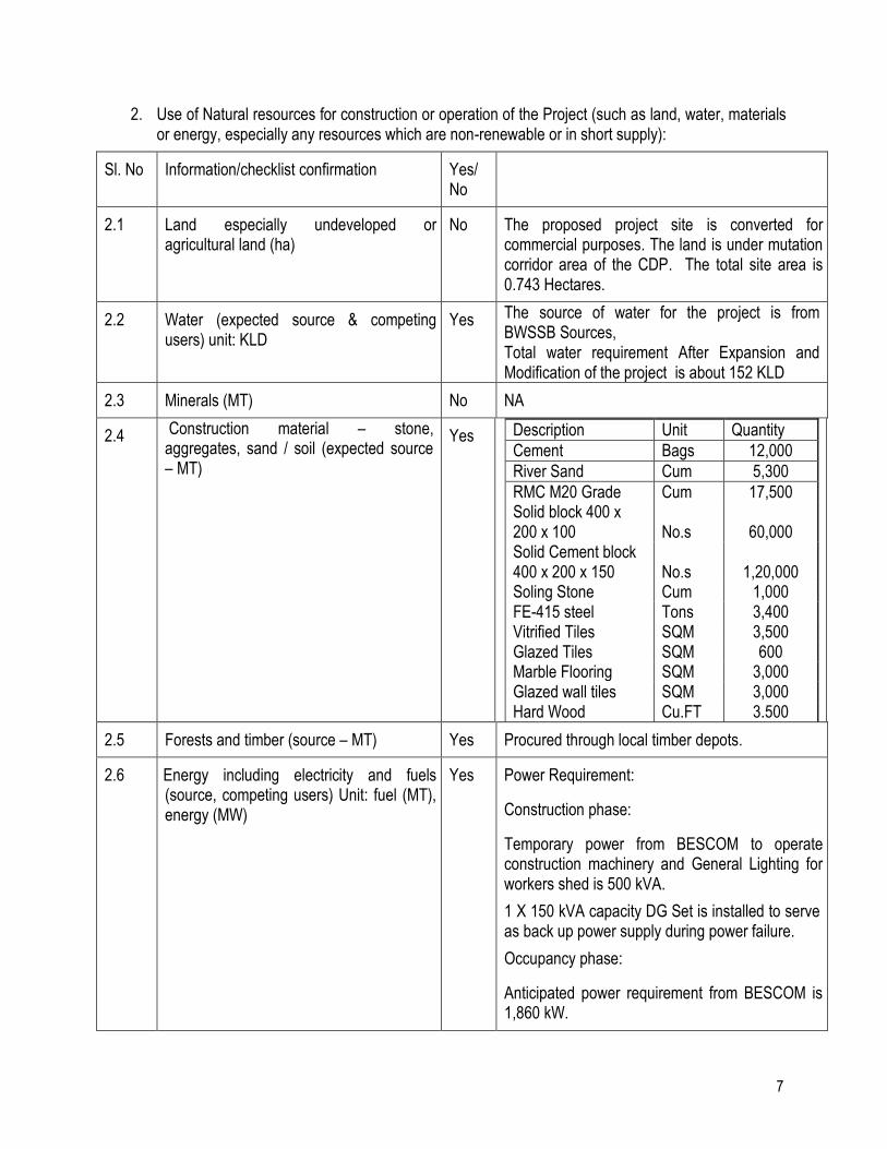
2. Use of Natural resources for construction or operation of the Project (such as land, water, materials or energy, especially any resources which are non-renewable or in short supply):
Sl. No Information/checklist confirmation Yes/ No
2.1 Land especially undeveloped or agricultural land (ha)
No The proposed project site is converted for commercial purposes. The land is under mutation corridor area of the CDP. The total site area is 0.743 Hectares.
2.2 Water (expected source & competing users) unit: KLD
Yes The source of water for the project is from BWSSB Sources, Total water requirement After Expansion and Modification of the project is about 152 KLD
2.3 Minerals (MT) No NA
2.4 Construction material – stone, aggregates, sand / soil (expected source – MT)
Yes Description Unit Quantity
Cement Bags 12,000
River Sand Cum 5,300
RMC M20 Grade Cum 17,500 Solid block 400 x 200 x 100 No.s 60,000 Solid Cement block 400 x 200 x 150 No.s 1,20,000 Soling Stone Cum 1,000 FE-415 steel Tons 3,400 Vitrified Tiles SQM 3,500 Glazed Tiles SQM 600 Marble Flooring SQM 3,000 Glazed wall tiles SQM 3,000 Hard Wood Cu.FT 3.500
2.5 Forests and timber (source – MT) Yes Procured through local timber depots.
2.6 Energy including electricity and fuels (source, competing users) Unit: fuel (MT), energy (MW)
Yes Power Requirement:
Construction phase:
Temporary power from BESCOM to operate construction machinery and General Lighting for workers shed is 500 kVA.
1 X 150 kVA capacity DG Set is installed to serve as back up power supply during power failure.
Occupancy phase:
Anticipated power requirement from BESCOM is 1,860 kW.
8
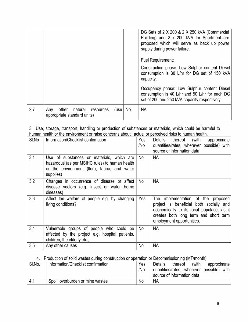
DG Sets of 2 X 200 & 2 X 250 kVA (Commercial Building) and 2 x 200 kVA for Apartment are proposed which will serve as back up power supply during power failure. Fuel Requirement:
Construction phase: Low Sulphur content Diesel consumption is 30 L/hr for DG set of 150 kVA capacity.
Occupancy phase: Low Sulphur content Diesel consumption is 40 L/hr and 50 L/hr for each DG set of 200 and 250 kVA capacity respectively.
2.7 Any other natural resources (use appropriate standard units)
No NA
3. Use, storage, transport, handling or production of substances or materials, which could be harmful to human health or the environment or raise concerns about actual or perceived risks to human health.
Sl.No Information/Checklist confirmation Yes /No
Details thereof (with approximate quantities/rates, wherever possible) with source of information data
3.1 Use of substances or materials, which are hazardous (as per MSIHC rules) to human health or the environment (flora, fauna, and water supplies)
No NA
3.2 Changes in occurrence of disease or affect disease vectors (e.g. insect or water borne diseases)
No NA
3.3 Affect the welfare of people e.g. by changing living conditions?
Yes The implementation of the proposed project is beneficial both socially and economically to its local populace, as it creates both long term and short term employment opportunities.
3.4 Vulnerable groups of people who could be affected by the project e.g. hospital patients, children, the elderly etc.,
No NA
3.5 Any other causes No NA
4. Production of solid wastes during construction or operation or Decommissioning (MT/month)
Sl.No. Information/Checklist confirmation Yes /No
Details thereof (with approximate quantities/rates, wherever possible) with source of information data
4.1 Spoil, overburden or mine wastes No NA
9
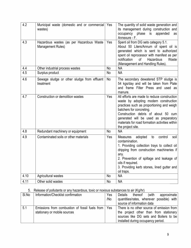
4.2 Municipal waste (domestic and or commercial wastes)
Yes The quantity of solid waste generation and its management during construction and occupancy phase is appended as Annexure - F.
4.3 Hazardous wastes (as per Hazardous Waste Management Rules)
Yes Spent oil from DG sets category 5.1. About 50 Liters/Annum of spent oil is generated which is sent to authorized spent oil reprocessor with manifest as per notification of Hazardous Waste (Management and Handling Rules).
4.4 Other industrial process wastes No NA
4.5 Surplus product No NA
4.6 Sewage sludge or other sludge from effluent treatment
No The secondary dewatered STP sludge is 54 kgs/day and will be taken from Plate and frame Filter Press and used as manure.
4.7 Construction or demolition wastes Yes All efforts are made to reduce construction waste by adopting modern construction practices such as proportioning and weigh batchers for concreting. Construction debris of about 50 cum generated will be used as preparatory materials for road formation activities within the project site.
4.8 Redundant machinery or equipment No NA
4.9 Contaminated soils or other materials Yes Measures adopted to control soil contamination. 1. Providing collection trays to collect oil dripping from construction machineries if any. 2. Prevention of spillage and leakage of oils if required. 3. Providing kerb stones, lined gutter and oil traps.
4.10 Agricultural wastes No NA
4.11 Other solid wastes No NA
5. Release of pollutants or any hazardous, toxic or noxious substances to air (Kg/hr)
Sl.No Information/Checklist confirmation Yes /No
Details thereof (with approximate quantities/rates, wherever possible) with source of information data
5.1 Emissions from combustion of fossil fuels from stationary or mobile sources
Yes There is no other source of emission from the project other than from stationary sources like DG sets and Boilers to be installed during occupancy period.
10
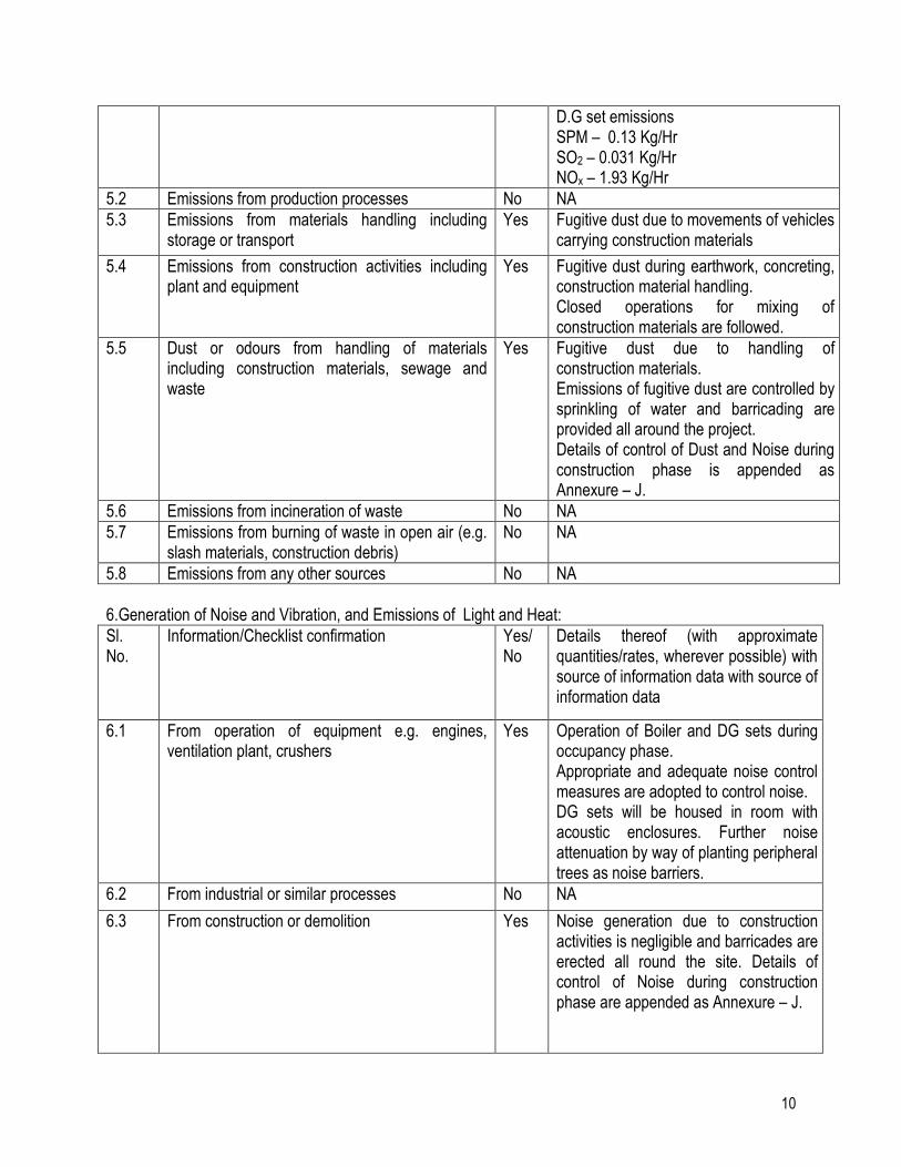
D.G set emissions SPM – 0.13 Kg/Hr SO2 – 0.031 Kg/Hr NOx – 1.93 Kg/Hr
5.2 Emissions from production processes No NA
5.3 Emissions from materials handling including storage or transport
Yes Fugitive dust due to movements of vehicles carrying construction materials
5.4 Emissions from construction activities including plant and equipment
Yes Fugitive dust during earthwork, concreting, construction material handling. Closed operations for mixing of construction materials are followed.
5.5 Dust or odours from handling of materials including construction materials, sewage and waste
Yes Fugitive dust due to handling of construction materials. Emissions of fugitive dust are controlled by sprinkling of water and barricading are provided all around the project. Details of control of Dust and Noise during construction phase is appended as Annexure – J.
5.6 Emissions from incineration of waste No NA
5.7 Emissions from burning of waste in open air (e.g. slash materials, construction debris)
No NA
5.8 Emissions from any other sources No NA
6.Generation of Noise and Vibration, and Emissions of Light and Heat:
Sl. No.
Information/Checklist confirmation Yes/ No
Details thereof (with approximate quantities/rates, wherever possible) with source of information data with source of information data
6.1 From operation of equipment e.g. engines, ventilation plant, crushers
Yes Operation of Boiler and DG sets during occupancy phase. Appropriate and adequate noise control measures are adopted to control noise. DG sets will be housed in room with acoustic enclosures. Further noise attenuation by way of planting peripheral trees as noise barriers.
6.2 From industrial or similar processes No NA
6.3 From construction or demolition Yes Noise generation due to construction activities is negligible and barricades are erected all round the site. Details of control of Noise during construction phase are appended as Annexure – J.
11
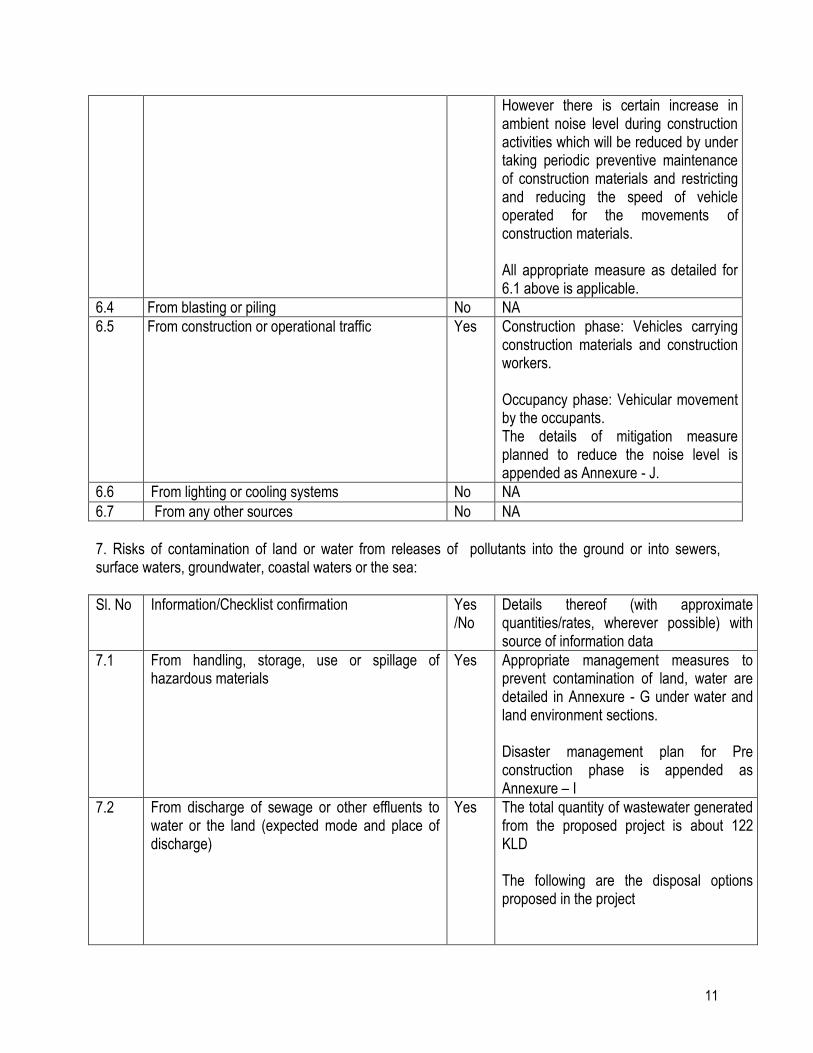
However there is certain increase in ambient noise level during construction activities which will be reduced by under taking periodic preventive maintenance of construction materials and restricting and reducing the speed of vehicle operated for the movements of construction materials. All appropriate measure as detailed for 6.1 above is applicable.
6.4 From blasting or piling No NA
6.5 From construction or operational traffic
Yes Construction phase: Vehicles carrying construction materials and construction workers. Occupancy phase: Vehicular movement by the occupants. The details of mitigation measure planned to reduce the noise level is appended as Annexure - J.
6.6 From lighting or cooling systems No NA
6.7 From any other sources No NA
7. Risks of contamination of land or water from releases of pollutants into the ground or into sewers, surface waters, groundwater, coastal waters or the sea:
Sl. No Information/Checklist confirmation Yes /No
Details thereof (with approximate quantities/rates, wherever possible) with source of information data
7.1 From handling, storage, use or spillage of hazardous materials
Yes Appropriate management measures to prevent contamination of land, water are detailed in Annexure - G under water and land environment sections. Disaster management plan for Pre construction phase is appended as Annexure – I
7.2 From discharge of sewage or other effluents to water or the land (expected mode and place of discharge)
Yes The total quantity of wastewater generated from the proposed project is about 122 KLD The following are the disposal options proposed in the project
12
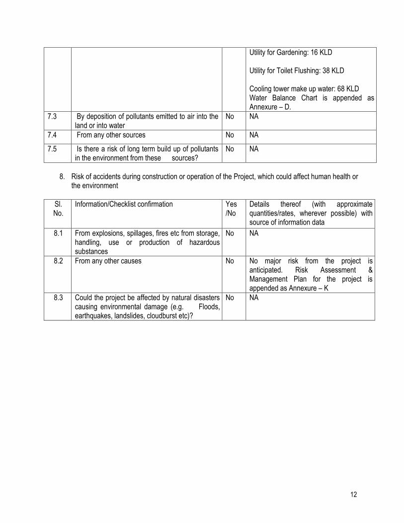
Utility for Gardening: 16 KLD Utility for Toilet Flushing: 38 KLD Cooling tower make up water: 68 KLD Water Balance Chart is appended as Annexure – D.
7.3 By deposition of pollutants emitted to air into the land or into water
No NA
7.4 From any other sources No NA
7.5 Is there a risk of long term build up of pollutants in the environment from these sources?
No NA
8. Risk of accidents during construction or operation of the Project, which could affect human health or
the environment
Sl. No.
Information/Checklist confirmation Yes /No
Details thereof (with approximate quantities/rates, wherever possible) with source of information data
8.1 From explosions, spillages, fires etc from storage, handling, use or production of hazardous substances
No NA
8.2 From any other causes No No major risk from the project is anticipated. Risk Assessment & Management Plan for the project is appended as Annexure – K
8.3 Could the project be affected by natural disasters causing environmental damage (e.g. Floods, earthquakes, landslides, cloudburst etc)?
No NA
13
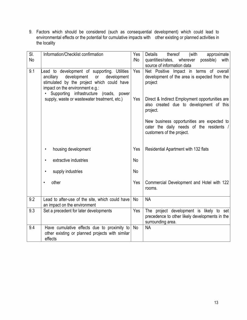
9. Factors which should be considered (such as consequential development) which could lead to environmental effects or the potential for cumulative impacts with other existing or planned activities in the locality
Sl. No
Information/Checklist confirmation Yes /No
Details thereof (with approximate quantities/rates, wherever possible) with source of information data
9.1 Lead Lead to development of supporting. Utilities ancillary development or development stimulated by the project which could have impact on the environment e.g.: • Supporting infrastructure (roads, power supply, waste or wastewater treatment, etc.)
• housing development • extractive industries • supply industries
• other
Yes Yes Yes No No Yes
Net Positive Impact in terms of overall development of the area is expected from the project Direct & Indirect Employment opportunities are also created due to development of this project. New business opportunities are expected to cater the daily needs of the residents / customers of the project. Residential Apartment with 132 flats Commercial Development and Hotel with 122 rooms.
9.2 Lead to after-use of the site, which could have an impact on the environment
No NA
9.3 Set a precedent for later developments Yes The project development is likely to set precedence to other likely developments in the surrounding area.
9.4 Have cumulative effects due to proximity to other existing or planned projects with similar effects
No NA
14
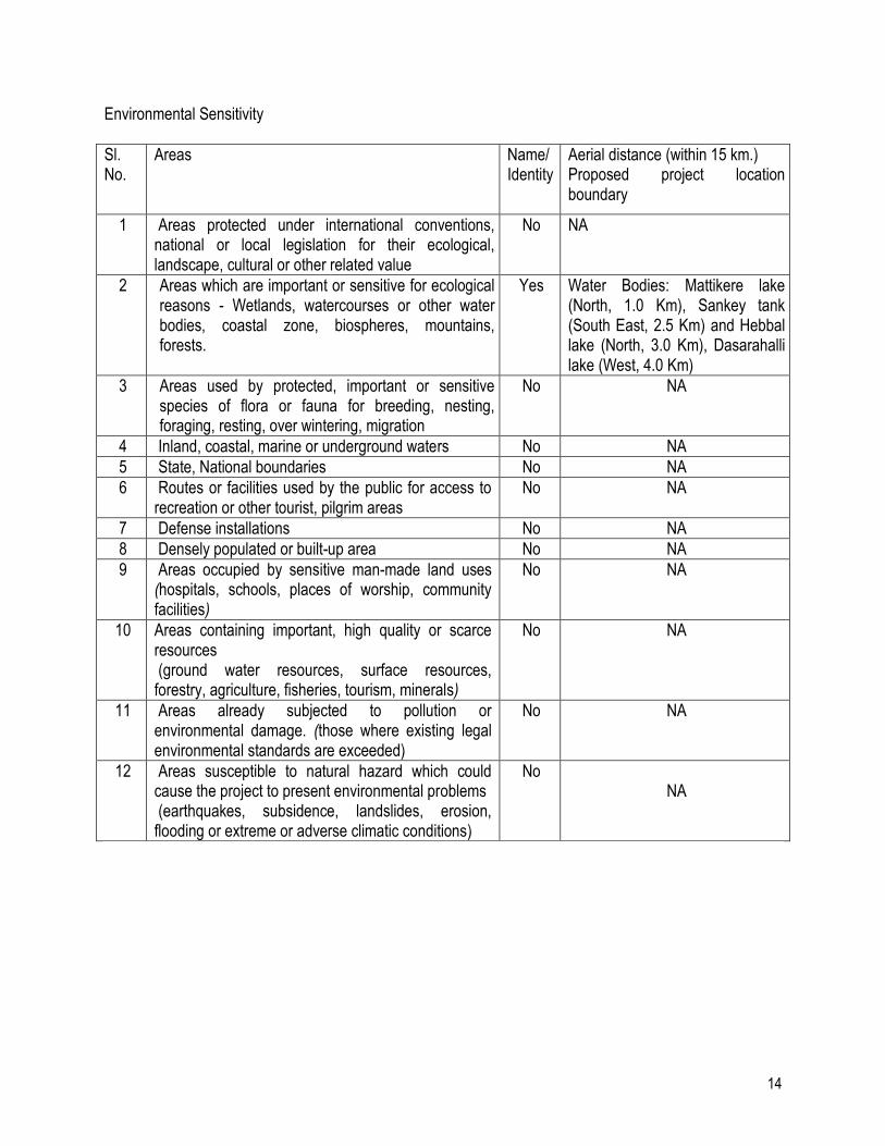
Environmental Sensitivity
Sl. No.
Areas Name/ Identity
Aerial distance (within 15 km.) Proposed project location boundary
1 Areas protected under international conventions, national or local legislation for their ecological, landscape, cultural or other related value
No NA
2 Areas which are important or sensitive for ecological reasons - Wetlands, watercourses or other water bodies, coastal zone, biospheres, mountains, forests.
Yes Water Bodies: Mattikere lake (North, 1.0 Km), Sankey tank (South East, 2.5 Km) and Hebbal lake (North, 3.0 Km), Dasarahalli lake (West, 4.0 Km)
3 Areas used by protected, important or sensitive species of flora or fauna for breeding, nesting, foraging, resting, over wintering, migration
No NA
4 Inland, coastal, marine or underground waters No NA
5 State, National boundaries No NA
6 Routes or facilities used by the public for access to recreation or other tourist, pilgrim areas
No NA
7 Defense installations No NA
8 Densely populated or built-up area No NA
9 Areas occupied by sensitive man-made land uses (hospitals, schools, places of worship, community facilities)
No NA
10 Areas containing important, high quality or scarce resources (ground water resources, surface resources, forestry, agriculture, fisheries, tourism, minerals)
No NA
11 Areas already subjected to pollution or environmental damage. (those where existing legal environmental standards are exceeded)
No NA
12 Areas susceptible to natural hazard which could cause the project to present environmental problems (earthquakes, subsidence, landslides, erosion, flooding or extreme or adverse climatic conditions)
No NA
15
APPENDIX II (See paragraph 6)
FORM -1 A
(Only for construction projects listed under item 8 of the Schedule)
CHECK LIST OF ENVIRONMENTAL IMPACTS
(Project proponents are required to provide full information and wherever necessary attach explanatory notes with the Form and submit along with proposed environmental management plan & monitoring program)
1. LAND ENVIRONMENT
(Attach panoramic view of the project site and the vicinity)
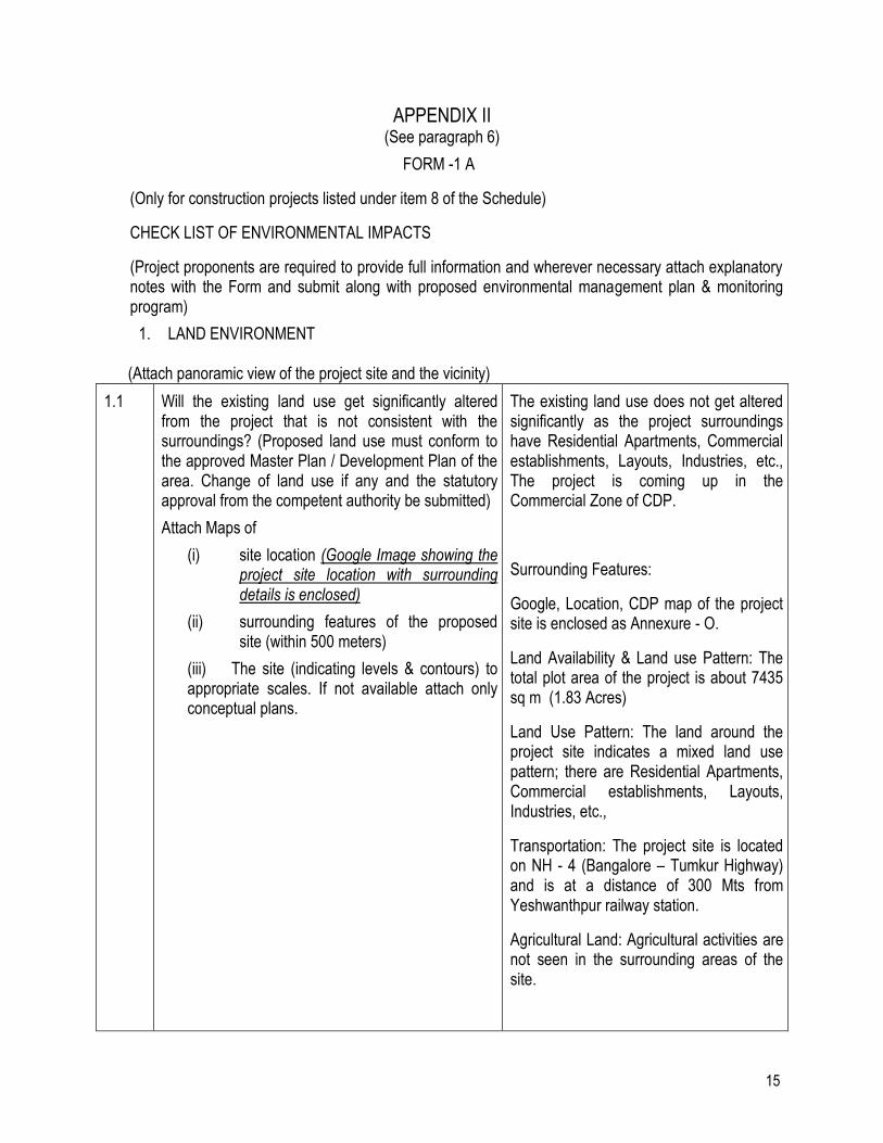
1.1 Will the existing land use get significantly altered from the project that is not consistent with the surroundings? (Proposed land use must conform to the approved Master Plan / Development Plan of the area. Change of land use if any and the statutory approval from the competent authority be submitted)
Attach Maps of
(i) site location (Google Image showing the project site location with surrounding details is enclosed)
(ii) surrounding features of the proposed site (within 500 meters)
(iii) The site (indicating levels & contours) to appropriate scales. If not available attach only conceptual plans.
The existing land use does not get altered significantly as the project surroundings have Residential Apartments, Commercial establishments, Layouts, Industries, etc., The project is coming up in the Commercial Zone of CDP.
Surrounding Features:
Google, Location, CDP map of the project site is enclosed as Annexure - O.
Land Availability & Land use Pattern: The total plot area of the project is about 7435 sq m (1.83 Acres)
Land Use Pattern: The land around the project site indicates a mixed land use pattern; there are Residential Apartments, Commercial establishments, Layouts, Industries, etc.,
Transportation: The project site is located on NH - 4 (Bangalore – Tumkur Highway) and is at a distance of 300 Mts from Yeshwanthpur railway station.
Agricultural Land: Agricultural activities are not seen in the surrounding areas of the site.
16
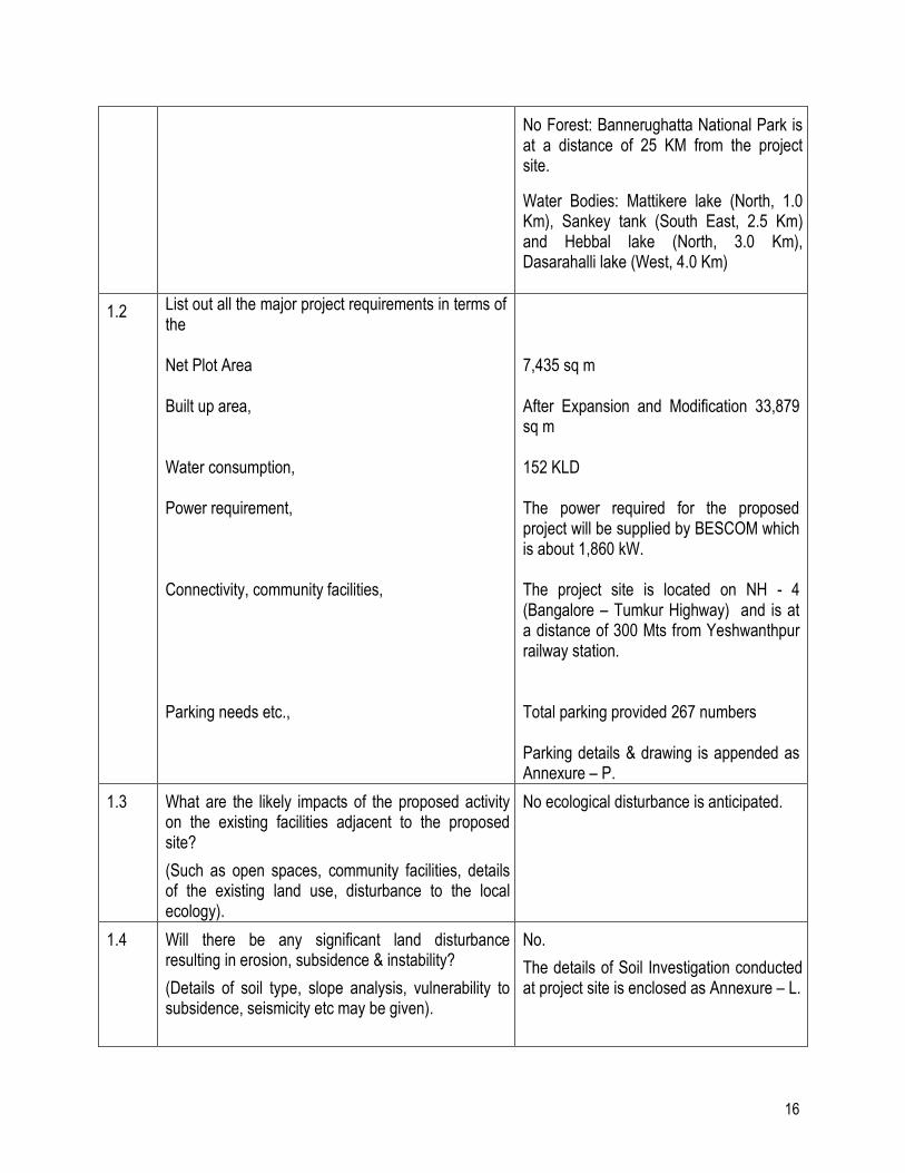
No Forest: Bannerughatta National Park is at a distance of 25 KM from the project site.
Water Bodies: Mattikere lake (North, 1.0 Km), Sankey tank (South East, 2.5 Km) and Hebbal lake (North, 3.0 Km), Dasarahalli lake (West, 4.0 Km)
1.2 List out all the major project requirements in terms of the Net Plot Area Built up area, Water consumption, Power requirement, Connectivity, community facilities, Parking needs etc.,
7,435 sq m After Expansion and Modification 33,879 sq m 152 KLD The power required for the proposed project will be supplied by BESCOM which is about 1,860 kW. The project site is located on NH - 4 (Bangalore – Tumkur Highway) and is at a distance of 300 Mts from Yeshwanthpur railway station. Total parking provided 267 numbers Parking details & drawing is appended as Annexure – P.
1.3 What are the likely impacts of the proposed activity on the existing facilities adjacent to the proposed site?
(Such as open spaces, community facilities, details of the existing land use, disturbance to the local ecology).
No ecological disturbance is anticipated.
1.4 Will there be any significant land disturbance resulting in erosion, subsidence & instability?
(Details of soil type, slope analysis, vulnerability to subsidence, seismicity etc may be given).
No.
The details of Soil Investigation conducted at project site is enclosed as Annexure – L.
17
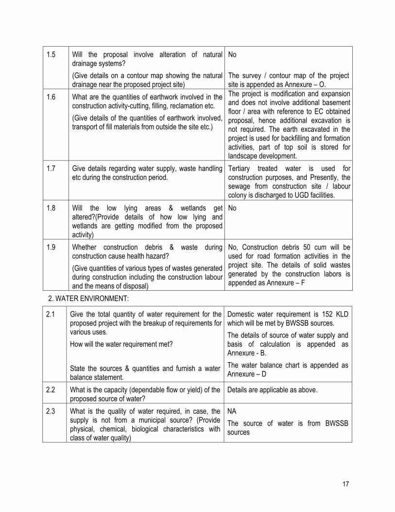
1.5 Will the proposal involve alteration of natural drainage systems?
(Give details on a contour map showing the natural drainage near the proposed project site)
No
The survey / contour map of the project site is appended as Annexure – O.
1.6 What are the quantities of earthwork involved in the construction activity-cutting, filling, reclamation etc.
(Give details of the quantities of earthwork involved, transport of fill materials from outside the site etc.)
The project is modification and expansion and does not involve additional basement floor / area with reference to EC obtained proposal, hence additional excavation is not required. The earth excavated in the project is used for backfilling and formation activities, part of top soil is stored for landscape development.
1.7 Give details regarding water supply, waste handling etc during the construction period.
Tertiary treated water is used for construction purposes, and Presently, the sewage from construction site / labour colony is discharged to UGD facilities.
1.8 Will the low lying areas & wetlands get altered?(Provide details of how low lying and wetlands are getting modified from the proposed activity)
No
1.9 Whether construction debris & waste during construction cause health hazard?
(Give quantities of various types of wastes generated during construction including the construction labour and the means of disposal)
No, Construction debris 50 cum will be used for road formation activities in the project site. The details of solid wastes generated by the construction labors is appended as Annexure – F
2. WATER ENVIRONMENT:
2.1 Give the total quantity of water requirement for the proposed project with the breakup of requirements for various uses.
How will the water requirement met?
State the sources & quantities and furnish a water balance statement.
Domestic water requirement is 152 KLD which will be met by BWSSB sources.
The details of source of water supply and basis of calculation is appended as Annexure - B.
The water balance chart is appended as Annexure – D
2.2 What is the capacity (dependable flow or yield) of the proposed source of water?
Details are applicable as above.
2.3 What is the quality of water required, in case, the supply is not from a municipal source? (Provide physical, chemical, biological characteristics with class of water quality)
NA
The source of water is from BWSSB sources
18
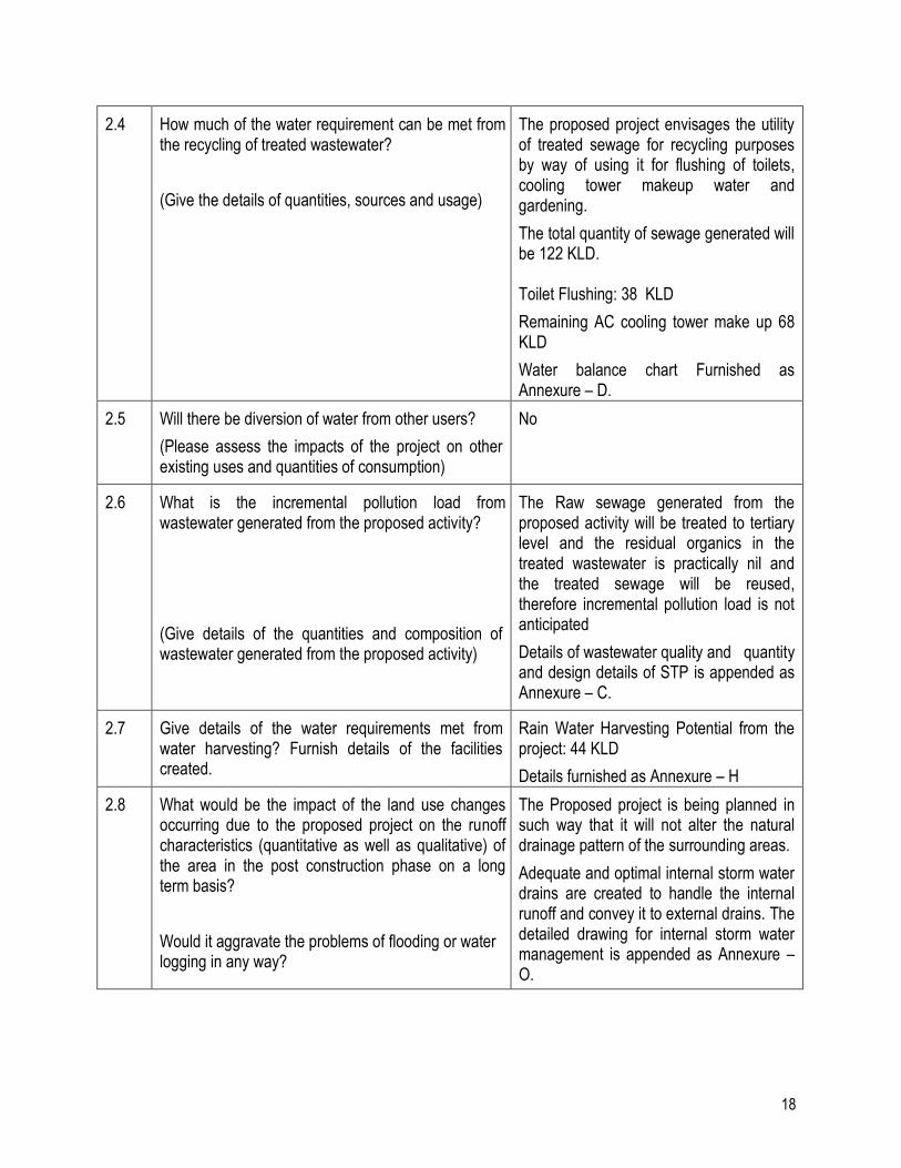
2.4 How much of the water requirement can be met from the recycling of treated wastewater?
(Give the details of quantities, sources and usage)
The proposed project envisages the utility of treated sewage for recycling purposes by way of using it for flushing of toilets, cooling tower makeup water and gardening.
The total quantity of sewage generated will be 122 KLD. Toilet Flushing: 38 KLD
Remaining AC cooling tower make up 68 KLD
Water balance chart Furnished as Annexure – D.
2.5 Will there be diversion of water from other users?
(Please assess the impacts of the project on other existing uses and quantities of consumption)
No
2.6 What is the incremental pollution load from wastewater generated from the proposed activity?
(Give details of the quantities and composition of wastewater generated from the proposed activity)
The Raw sewage generated from the proposed activity will be treated to tertiary level and the residual organics in the treated wastewater is practically nil and the treated sewage will be reused, therefore incremental pollution load is not anticipated
Details of wastewater quality and quantity and design details of STP is appended as Annexure – C.
2.7 Give details of the water requirements met from water harvesting? Furnish details of the facilities created.
Rain Water Harvesting Potential from the project: 44 KLD
Details furnished as Annexure – H
2.8 What would be the impact of the land use changes occurring due to the proposed project on the runoff characteristics (quantitative as well as qualitative) of the area in the post construction phase on a long term basis?
Would it aggravate the problems of flooding or water logging in any way?
The Proposed project is being planned in such way that it will not alter the natural drainage pattern of the surrounding areas.
Adequate and optimal internal storm water drains are created to handle the internal runoff and convey it to external drains. The detailed drawing for internal storm water management is appended as Annexure – O.
19
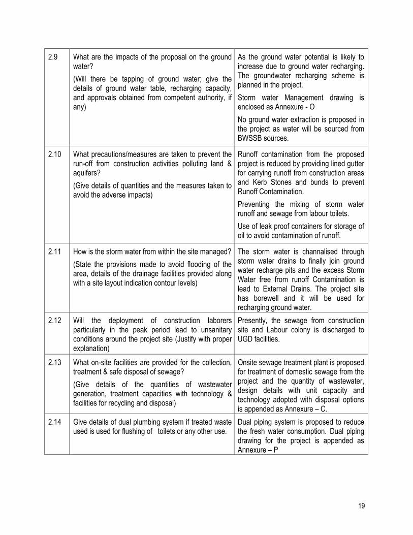
2.9 What are the impacts of the proposal on the ground water?
(Will there be tapping of ground water; give the details of ground water table, recharging capacity, and approvals obtained from competent authority, if any)
As the ground water potential is likely to increase due to ground water recharging. The groundwater recharging scheme is planned in the project.
Storm water Management drawing is enclosed as Annexure - O
No ground water extraction is proposed in the project as water will be sourced from BWSSB sources.
2.10 What precautions/measures are taken to prevent the run-off from construction activities polluting land & aquifers?
(Give details of quantities and the measures taken to avoid the adverse impacts)
Runoff contamination from the proposed project is reduced by providing lined gutter for carrying runoff from construction areas and Kerb Stones and bunds to prevent Runoff Contamination.
Preventing the mixing of storm water runoff and sewage from labour toilets.
Use of leak proof containers for storage of oil to avoid contamination of runoff.
2.11 How is the storm water from within the site managed?
(State the provisions made to avoid flooding of the area, details of the drainage facilities provided along with a site layout indication contour levels)
The storm water is channalised through storm water drains to finally join ground water recharge pits and the excess Storm Water free from runoff Contamination is lead to External Drains. The project site has borewell and it will be used for recharging ground water.
2.12 Will the deployment of construction laborers particularly in the peak period lead to unsanitary conditions around the project site (Justify with proper explanation)
Presently, the sewage from construction site and Labour colony is discharged to UGD facilities.
2.13 What on-site facilities are provided for the collection, treatment & safe disposal of sewage?
(Give details of the quantities of wastewater generation, treatment capacities with technology & facilities for recycling and disposal)
Onsite sewage treatment plant is proposed for treatment of domestic sewage from the project and the quantity of wastewater, design details with unit capacity and technology adopted with disposal options is appended as Annexure – C.
2.14 Give details of dual plumbing system if treated waste used is used for flushing of toilets or any other use.
Dual piping system is proposed to reduce the fresh water consumption. Dual piping drawing for the project is appended as Annexure – P
20
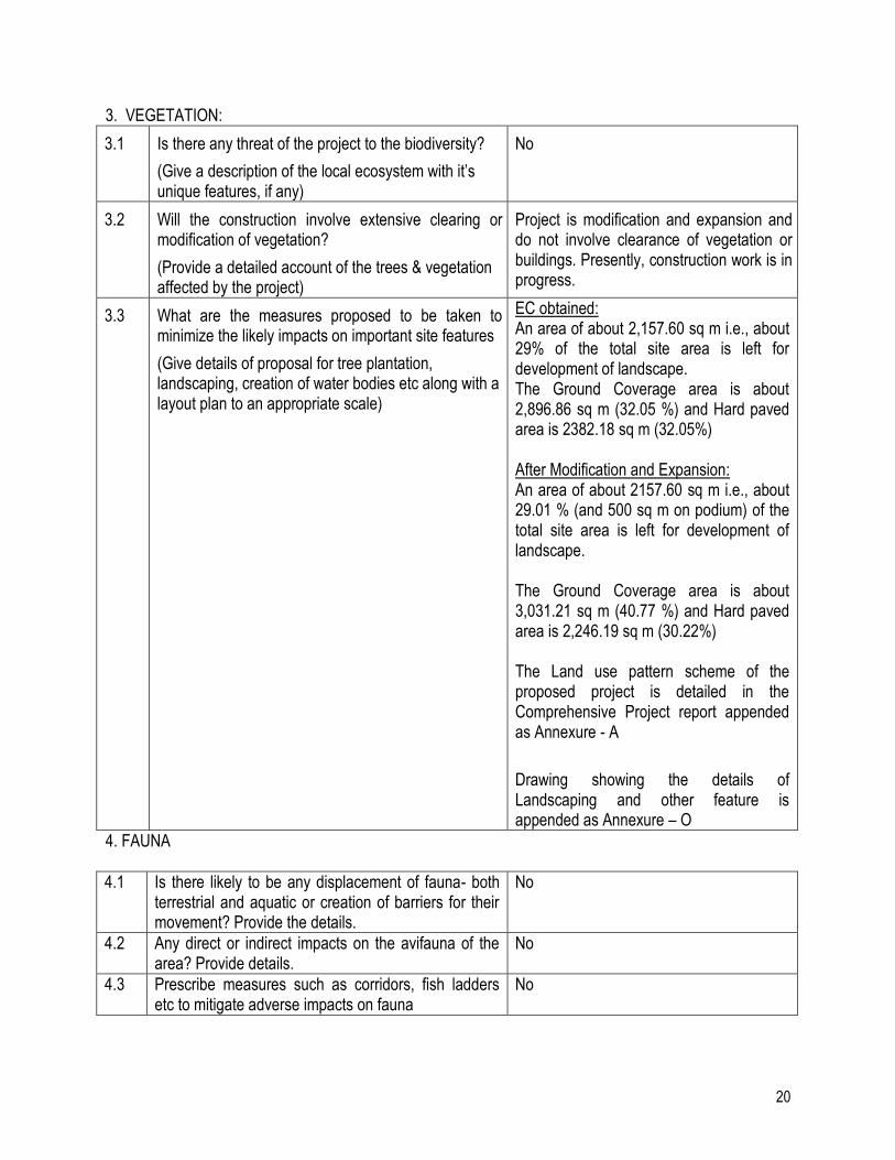
3. VEGETATION:
3.1 Is there any threat of the project to the biodiversity?
(Give a description of the local ecosystem with it’s unique features, if any)
No
3.2 Will the construction involve extensive clearing or modification of vegetation?
(Provide a detailed account of the trees & vegetation affected by the project)
Project is modification and expansion and do not involve clearance of vegetation or buildings. Presently, construction work is in progress.
3.3 What are the measures proposed to be taken to minimize the likely impacts on important site features
(Give details of proposal for tree plantation, landscaping, creation of water bodies etc along with a layout plan to an appropriate scale)
EC obtained: An area of about 2,157.60 sq m i.e., about 29% of the total site area is left for development of landscape. The Ground Coverage area is about 2,896.86 sq m (32.05 %) and Hard paved area is 2382.18 sq m (32.05%) After Modification and Expansion: An area of about 2157.60 sq m i.e., about 29.01 % (and 500 sq m on podium) of the total site area is left for development of landscape. The Ground Coverage area is about 3,031.21 sq m (40.77 %) and Hard paved area is 2,246.19 sq m (30.22%) The Land use pattern scheme of the proposed project is detailed in the Comprehensive Project report appended as Annexure - A
Drawing showing the details of Landscaping and other feature is appended as Annexure – O
4. FAUNA
4.1 Is there likely to be any displacement of fauna- both terrestrial and aquatic or creation of barriers for their movement? Provide the details.
No
4.2 Any direct or indirect impacts on the avifauna of the area? Provide details.
No
4.3 Prescribe measures such as corridors, fish ladders etc to mitigate adverse impacts on fauna
No
21
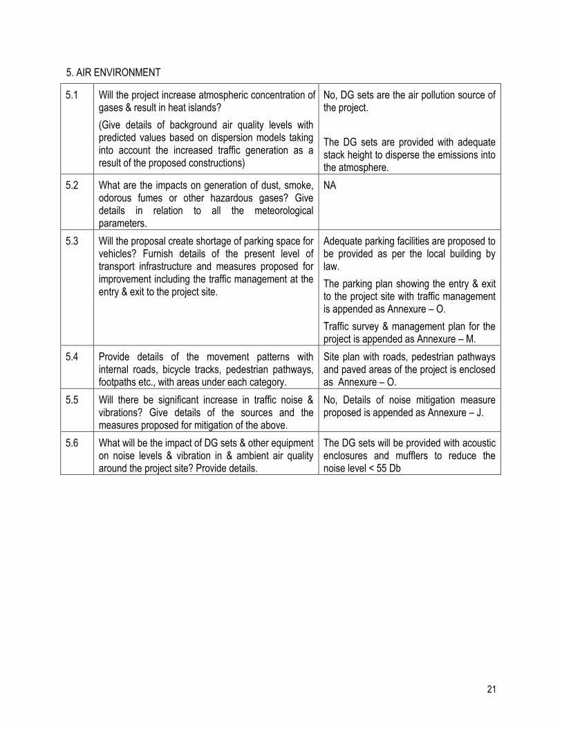
5. AIR ENVIRONMENT
5.1 Will the project increase atmospheric concentration of gases & result in heat islands?
(Give details of background air quality levels with predicted values based on dispersion models taking into account the increased traffic generation as a result of the proposed constructions)
No, DG sets are the air pollution source of the project.
The DG sets are provided with adequate stack height to disperse the emissions into the atmosphere.
5.2 What are the impacts on generation of dust, smoke, odorous fumes or other hazardous gases? Give details in relation to all the meteorological parameters.
NA
5.3 Will the proposal create shortage of parking space for vehicles? Furnish details of the present level of transport infrastructure and measures proposed for improvement including the traffic management at the entry & exit to the project site.
Adequate parking facilities are proposed to be provided as per the local building by law.
The parking plan showing the entry & exit to the project site with traffic management is appended as Annexure – O.
Traffic survey & management plan for the project is appended as Annexure – M.
5.4 Provide details of the movement patterns with internal roads, bicycle tracks, pedestrian pathways, footpaths etc., with areas under each category.
Site plan with roads, pedestrian pathways and paved areas of the project is enclosed as Annexure – O.
5.5 Will there be significant increase in traffic noise & vibrations? Give details of the sources and the measures proposed for mitigation of the above.
No, Details of noise mitigation measure proposed is appended as Annexure – J.
5.6 What will be the impact of DG sets & other equipment on noise levels & vibration in & ambient air quality around the project site? Provide details.
The DG sets will be provided with acoustic enclosures and mufflers to reduce the noise level < 55 Db
22
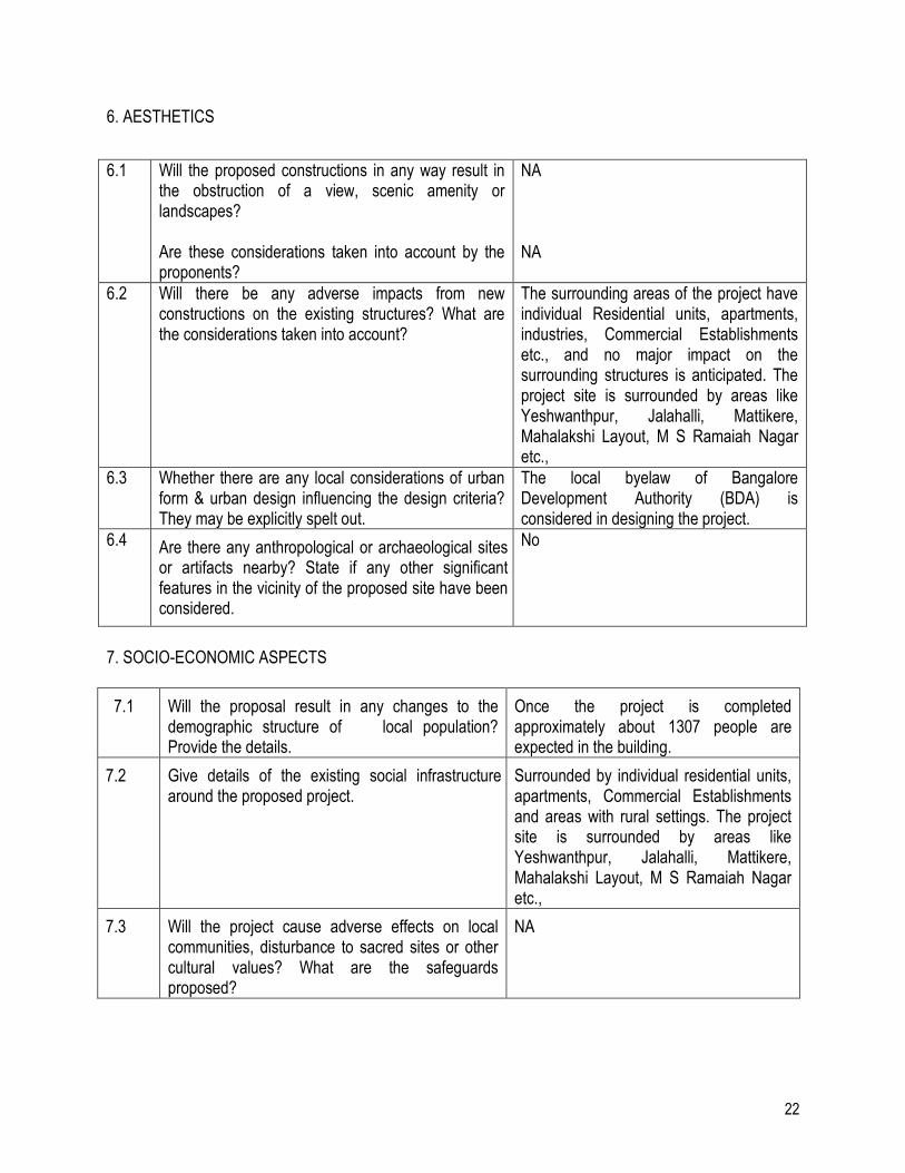
6. AESTHETICS
7. SOCIO-ECONOMIC ASPECTS
7.1 Will the proposal result in any changes to the demographic structure of local population? Provide the details.
Once the project is completed approximately about 1307 people are expected in the building.
7.2 Give details of the existing social infrastructure around the proposed project.
Surrounded by individual residential units, apartments, Commercial Establishments and areas with rural settings. The project site is surrounded by areas like Yeshwanthpur, Jalahalli, Mattikere, Mahalakshi Layout, M S Ramaiah Nagar etc.,
7.3 Will the project cause adverse effects on local communities, disturbance to sacred sites or other cultural values? What are the safeguards proposed?
NA
6.1 Will the proposed constructions in any way result in the obstruction of a view, scenic amenity or landscapes? Are these considerations taken into account by the proponents?
NA NA
6.2 Will there be any adverse impacts from new constructions on the existing structures? What are the considerations taken into account?
The surrounding areas of the project have individual Residential units, apartments, industries, Commercial Establishments etc., and no major impact on the surrounding structures is anticipated. The project site is surrounded by areas like Yeshwanthpur, Jalahalli, Mattikere, Mahalakshi Layout, M S Ramaiah Nagar etc.,
6.3 Whether there are any local considerations of urban form & urban design influencing the design criteria? They may be explicitly spelt out.
The local byelaw of Bangalore Development Authority (BDA) is considered in designing the project.
6.4 Are there any anthropological or archaeological sites or artifacts nearby? State if any other significant features in the vicinity of the proposed site have been considered.
No
23
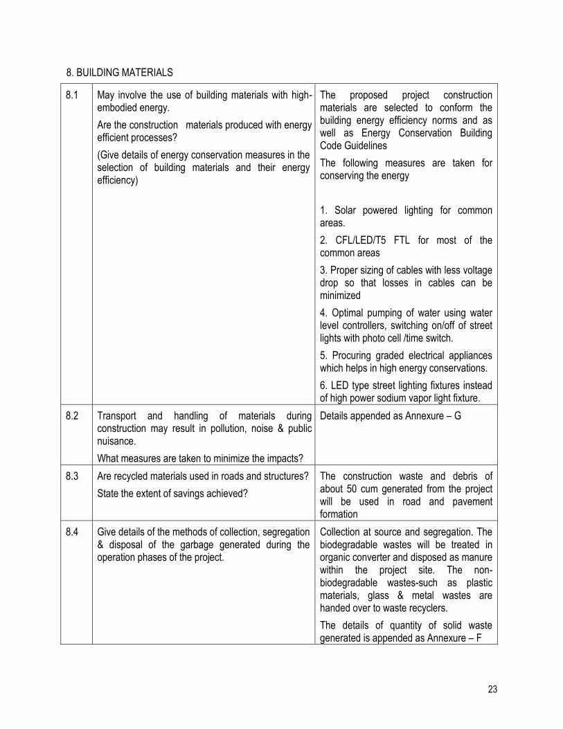
8. BUILDING MATERIALS
8.1 May involve the use of building materials with high-embodied energy.
Are the construction materials produced with energy efficient processes?
(Give details of energy conservation measures in the selection of building materials and their energy efficiency)
The proposed project construction materials are selected to conform the building energy efficiency norms and as well as Energy Conservation Building Code Guidelines
The following measures are taken for conserving the energy
1. Solar powered lighting for common areas.
2. CFL/LED/T5 FTL for most of the common areas
3. Proper sizing of cables with less voltage drop so that losses in cables can be minimized
4. Optimal pumping of water using water level controllers, switching on/off of street lights with photo cell /time switch.
5. Procuring graded electrical appliances which helps in high energy conservations.
6. LED type street lighting fixtures instead of high power sodium vapor light fixture.
8.2 Transport and handling of materials during construction may result in pollution, noise & public nuisance.
What measures are taken to minimize the impacts?
Details appended as Annexure – G
8.3 Are recycled materials used in roads and structures?
State the extent of savings achieved?
The construction waste and debris of about 50 cum generated from the project will be used in road and pavement formation
8.4 Give details of the methods of collection, segregation & disposal of the garbage generated during the operation phases of the project.
Collection at source and segregation. The biodegradable wastes will be treated in organic converter and disposed as manure within the project site. The non-biodegradable wastes-such as plastic materials, glass & metal wastes are handed over to waste recyclers.
The details of quantity of solid waste generated is appended as Annexure – F
24
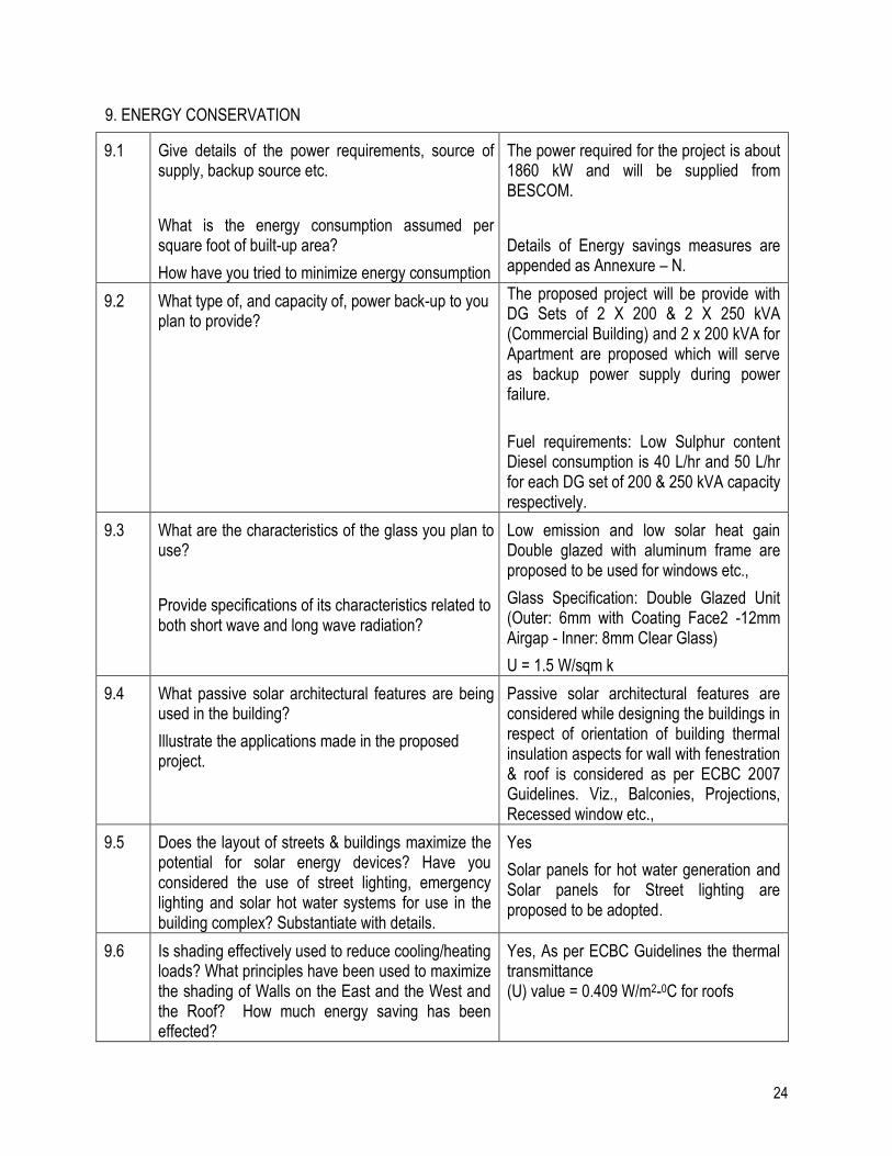
9. ENERGY CONSERVATION
9.1 Give details of the power requirements, source of supply, backup source etc.
What is the energy consumption assumed per square foot of built-up area?
How have you tried to minimize energy consumption
The power required for the project is about 1860 kW and will be supplied from BESCOM.
Details of Energy savings measures are appended as Annexure – N.
9.2 What type of, and capacity of, power back-up to you plan to provide?
The proposed project will be provide with DG Sets of 2 X 200 & 2 X 250 kVA (Commercial Building) and 2 x 200 kVA for Apartment are proposed which will serve as backup power supply during power failure.
Fuel requirements: Low Sulphur content Diesel consumption is 40 L/hr and 50 L/hr for each DG set of 200 & 250 kVA capacity respectively.
9.3 What are the characteristics of the glass you plan to use?
Provide specifications of its characteristics related to both short wave and long wave radiation?
Low emission and low solar heat gain Double glazed with aluminum frame are proposed to be used for windows etc.,
Glass Specification: Double Glazed Unit (Outer: 6mm with Coating Face2 -12mm Airgap - Inner: 8mm Clear Glass)
U = 1.5 W/sqm k
9.4 What passive solar architectural features are being used in the building?
Illustrate the applications made in the proposed project.
Passive solar architectural features are considered while designing the buildings in respect of orientation of building thermal insulation aspects for wall with fenestration & roof is considered as per ECBC 2007 Guidelines. Viz., Balconies, Projections, Recessed window etc.,
9.5 Does the layout of streets & buildings maximize the potential for solar energy devices? Have you considered the use of street lighting, emergency lighting and solar hot water systems for use in the building complex? Substantiate with details.
Yes
Solar panels for hot water generation and Solar panels for Street lighting are proposed to be adopted.
9.6 Is shading effectively used to reduce cooling/heating loads? What principles have been used to maximize the shading of Walls on the East and the West and the Roof? How much energy saving has been effected?
Yes, As per ECBC Guidelines the thermal transmittance (U) value = 0.409 W/m2-0C for roofs
25
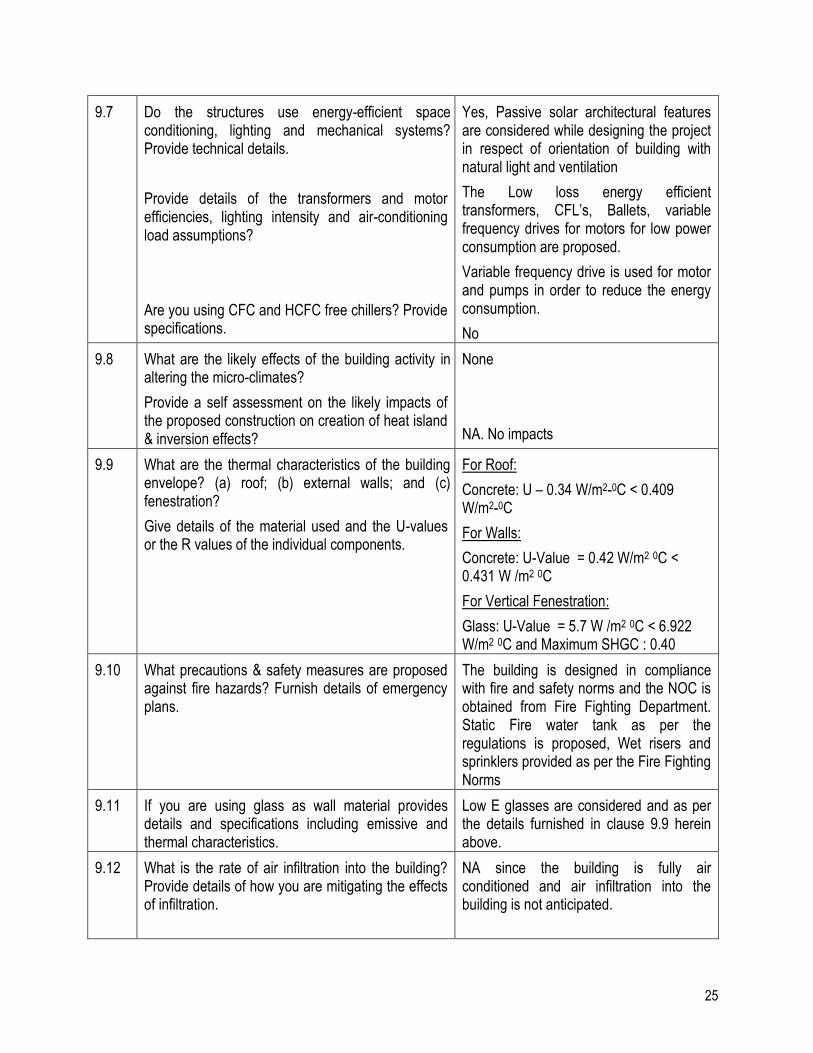
9.7 Do the structures use energy-efficient space conditioning, lighting and mechanical systems? Provide technical details.
Provide details of the transformers and motor efficiencies, lighting intensity and air-conditioning load assumptions?
Are you using CFC and HCFC free chillers? Provide specifications.
Yes, Passive solar architectural features are considered while designing the project in respect of orientation of building with natural light and ventilation
The Low loss energy efficient transformers, CFL’s, Ballets, variable frequency drives for motors for low power consumption are proposed.
Variable frequency drive is used for motor and pumps in order to reduce the energy consumption.
No
9.8 What are the likely effects of the building activity in altering the micro-climates?
Provide a self assessment on the likely impacts of the proposed construction on creation of heat island & inversion effects?
None
NA. No impacts
9.9 What are the thermal characteristics of the building envelope? (a) roof; (b) external walls; and (c) fenestration?
Give details of the material used and the U-values or the R values of the individual components.
For Roof:
Concrete: U – 0.34 W/m2-0C < 0.409 W/m2-0C
For Walls:
Concrete: U-Value = 0.42 W/m2 0C < 0.431 W /m2 0C
For Vertical Fenestration:
Glass: U-Value = 5.7 W /m2 0C < 6.922 W/m2 0C and Maximum SHGC : 0.40
9.10 What precautions & safety measures are proposed against fire hazards? Furnish details of emergency plans.
The building is designed in compliance with fire and safety norms and the NOC is obtained from Fire Fighting Department. Static Fire water tank as per the regulations is proposed, Wet risers and sprinklers provided as per the Fire Fighting Norms
9.11 If you are using glass as wall material provides details and specifications including emissive and thermal characteristics.
Low E glasses are considered and as per the details furnished in clause 9.9 herein above.
9.12 What is the rate of air infiltration into the building? Provide details of how you are mitigating the effects of infiltration.
NA since the building is fully air conditioned and air infiltration into the building is not anticipated.

26
9.13 To what extent the non-conventional energy technologies are utilized in the overall energy consumption?
Provide details of the renewable energy technologies used.
Solar heating and Solar Street lighting systems are proposed.
10. Environment Management Plan:
10.1 The Environment Management Plan would consist of all mitigation measures for each item wise activity to be undertaken during the construction, operation and the entire life cycle to minimize adverse environmental impacts as a result of the activities of the project. It would also delineate the environmental monitoring plan for compliance of various environmental regulations. It will state the steps to be taken in case of emergency such as accidents at the site including fire.
Wet risers / down riser, fire alarm system, automatic sprinklers system, and portable fire extinguishers are proposed in case of fire accidents.
Details of mitigation measures to minimize adverse environmental impacts during construction and operation phase of the project is appended in Environmental Monitoring plan is enclosed as Annexure - G.
“I hereby give undertaking that the data and information given in the application and enclosures are true to the best of my knowledge and belief and I am aware that if any part of the data and information submitted is found to be false or misleading at any stage, the project will be rejected and clearance give, if any to the project will be revoked at our risk and cost. Date: 27.10.2015. Place: BANGALORE.
SHARATH RUKMANGADA, Co-owner,
M/s. Shashikiran Investments, No. 67, “Lavina Courts”, First Floor,
102, 7th cross, 8th Main, RMV Extension, Bangalore - 560 080.
Signature of the applicant
With Name and Full address (Project Proponent / Authorized Signatory)

M/s. Shashikiran Investments
ANNEXURE TO APPLICATIONS
27
Annexure & Details to Application in Form 1 and Form 1A
M/s. Shashikiran Investments
ANNEXURE TO APPLICATIONS
28
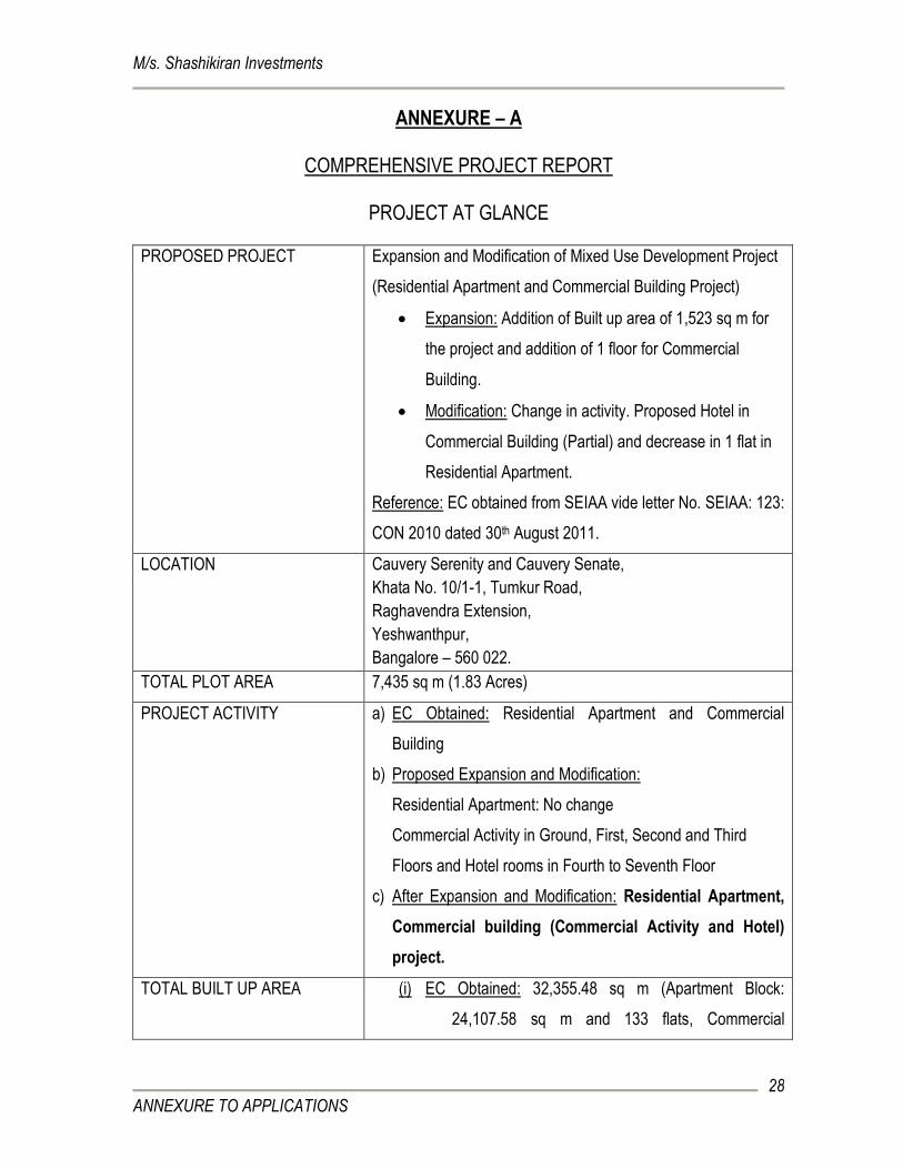
ANNEXURE – A
COMPREHENSIVE PROJECT REPORT
PROJECT AT GLANCE
PROPOSED PROJECT Expansion and Modification of Mixed Use Development Project
(Residential Apartment and Commercial Building Project)
Expansion: Addition of Built up area of 1,523 sq m for
the project and addition of 1 floor for Commercial
Building.
Modification: Change in activity. Proposed Hotel in
Commercial Building (Partial) and decrease in 1 flat in
Residential Apartment.
Reference: EC obtained from SEIAA vide letter No. SEIAA: 123:
CON 2010 dated 30th August 2011.
LOCATION Cauvery Serenity and Cauvery Senate,
Khata No. 10/1-1, Tumkur Road,
Raghavendra Extension,
Yeshwanthpur,
Bangalore – 560 022.
TOTAL PLOT AREA 7,435 sq m (1.83 Acres)
PROJECT ACTIVITY a) EC Obtained: Residential Apartment and Commercial
Building
b) Proposed Expansion and Modification:
Residential Apartment: No change
Commercial Activity in Ground, First, Second and Third
Floors and Hotel rooms in Fourth to Seventh Floor
c) After Expansion and Modification: Residential Apartment,
Commercial building (Commercial Activity and Hotel)
project.
TOTAL BUILT UP AREA (i) EC Obtained: 32,355.48 sq m (Apartment Block:
24,107.58 sq m and 133 flats, Commercial
M/s. Shashikiran Investments
ANNEXURE TO APPLICATIONS
29
Building: 8,247.90 sq m)
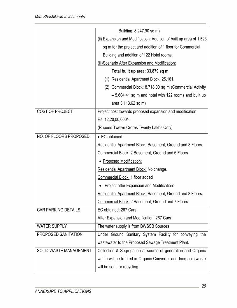
(ii) Expansion and Modification: Addition of built up area of 1,523
sq m for the project and addition of 1 floor for Commercial
Building and addition of 122 Hotel rooms.
(iii) Scenario After Expansion and Modification:
Total built up area: 33,879 sq m
(1) Residential Apartment Block: 25,161,
(2) Commercial Block: 8,718.00 sq m (Commercial Activity
– 5,604.41 sq m and hotel with 122 rooms and built up
area 3,113.62 sq m)
COST OF PROJECT Project cost towards proposed expansion and modification:
Rs. 12,20,00,000/-
(Rupees Twelve Crores Twenty Lakhs Only)
NO. OF FLOORS PROPOSED
EC obtained:
Residential Apartment Block: Basement, Ground and 8 Floors.
Commercial Block: 2 Basement, Ground and 6 Floors
Proposed Modification:
Residential Apartment Block: No change.
Commercial Block: 1 floor added
Project after Expansion and Modification:
Residential Apartment Block: Basement, Ground and 8 Floors.
Commercial Block: 2 Basement, Ground and 7 Floors.
CAR PARKING DETAILS EC obtained: 267 Cars
After Expansion and Modification: 267 Cars
WATER SUPPLY The water supply is from BWSSB Sources
PROPOSED SANITATION Under Ground Sanitary System Facility for conveying the
wastewater to the Proposed Sewage Treatment Plant.
SOLID WASTE MANAGEMENT Collection & Segregation at source of generation and Organic
waste will be treated in Organic Converter and Inorganic waste
will be sent for recycling.
M/s. Shashikiran Investments
ANNEXURE TO APPLICATIONS
30
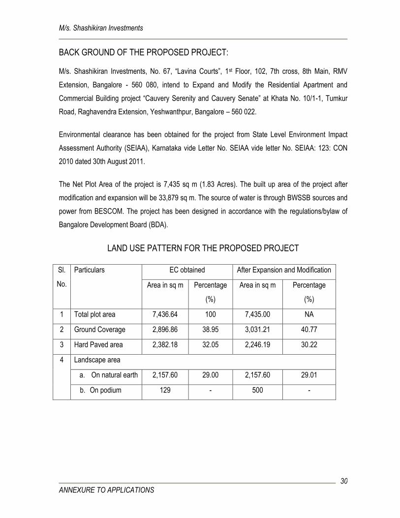
BACK GROUND OF THE PROPOSED PROJECT:
M/s. Shashikiran Investments, No. 67, “Lavina Courts”, 1st Floor, 102, 7th cross, 8th Main, RMV
Extension, Bangalore - 560 080, intend to Expand and Modify the Residential Apartment and
Commercial Building project “Cauvery Serenity and Cauvery Senate” at Khata No. 10/1-1, Tumkur
Road, Raghavendra Extension, Yeshwanthpur, Bangalore – 560 022.
Environmental clearance has been obtained for the project from State Level Environment Impact
Assessment Authority (SEIAA), Karnataka vide Letter No. SEIAA vide letter No. SEIAA: 123: CON
2010 dated 30th August 2011.
The Net Plot Area of the project is 7,435 sq m (1.83 Acres). The built up area of the project after
modification and expansion will be 33,879 sq m. The source of water is through BWSSB sources and
power from BESCOM. The project has been designed in accordance with the regulations/bylaw of
Bangalore Development Board (BDA).
LAND USE PATTERN FOR THE PROPOSED PROJECT
Sl.
No.
Particulars EC obtained After Expansion and Modification
Area in sq m Percentage
(%)
Area in sq m Percentage
(%)
1 Total plot area 7,436.64 100 7,435.00 NA
2 Ground Coverage 2,896.86 38.95 3,031.21 40.77
3 Hard Paved area 2,382.18 32.05 2,246.19 30.22
4 Landscape area
a. On natural earth 2,157.60 29.00 2,157.60 29.01
b. On podium 129 - 500 -
M/s. Shashikiran Investments
ANNEXURE TO APPLICATIONS
31
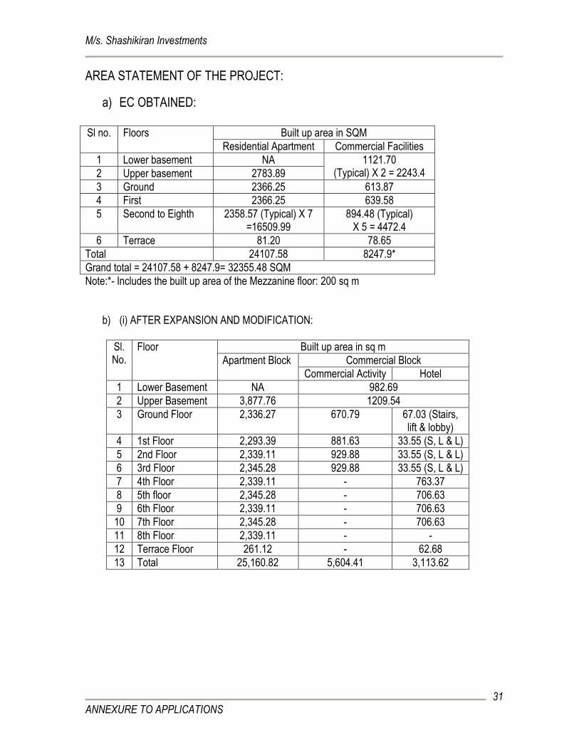
AREA STATEMENT OF THE PROJECT:
a) EC OBTAINED:
Sl no. Floors Built up area in SQM
Residential Apartment Commercial Facilities
1 Lower basement NA 1121.70 (Typical) X 2 = 2243.4 2 Upper basement 2783.89
3 Ground 2366.25 613.87
4 First 2366.25 639.58
5 Second to Eighth 2358.57 (Typical) X 7 =16509.99
894.48 (Typical) X 5 = 4472.4
6 Terrace 81.20 78.65
Total 24107.58 8247.9*
Grand total = 24107.58 + 8247.9= 32355.48 SQM
Note:*- Includes the built up area of the Mezzanine floor: 200 sq m
b) (i) AFTER EXPANSION AND MODIFICATION:
Sl. No.
Floor Built up area in sq m
Apartment Block Commercial Block
Commercial Activity Hotel
1 Lower Basement NA 982.69
2 Upper Basement 3,877.76 1209.54
3 Ground Floor 2,336.27 670.79 67.03 (Stairs, lift & lobby)
4 1st Floor 2,293.39 881.63 33.55 (S, L & L)
5 2nd Floor 2,339.11 929.88 33.55 (S, L & L)
6 3rd Floor 2,345.28 929.88 33.55 (S, L & L)
7 4th Floor 2,339.11 - 763.37
8 5th floor 2,345.28 - 706.63
9 6th Floor 2,339.11 - 706.63
10 7th Floor 2,345.28 - 706.63
11 8th Floor 2,339.11 - -
12 Terrace Floor 261.12 - 62.68
13 Total 25,160.82 5,604.41 3,113.62
M/s. Shashikiran Investments
ANNEXURE TO APPLICATIONS
32
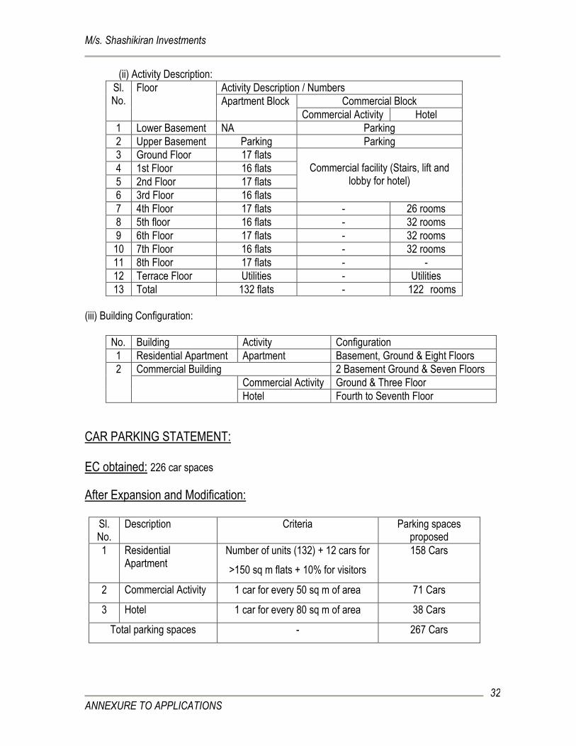
(ii) Activity Description:
Sl. No.
Floor Activity Description / Numbers
Apartment Block Commercial Block
Commercial Activity Hotel
1 Lower Basement NA Parking
2 Upper Basement Parking Parking
3 Ground Floor 17 flats Commercial facility (Stairs, lift and
lobby for hotel) 4 1st Floor 16 flats
5 2nd Floor 17 flats
6 3rd Floor 16 flats
7 4th Floor 17 flats - 26 rooms
8 5th floor 16 flats - 32 rooms
9 6th Floor 17 flats - 32 rooms
10 7th Floor 16 flats - 32 rooms
11 8th Floor 17 flats - -
12 Terrace Floor Utilities - Utilities
13 Total 132 flats - 122 rooms
(iii) Building Configuration:
No. Building Activity Configuration
1 Residential Apartment Apartment Basement, Ground & Eight Floors
2 Commercial Building 2 Basement Ground & Seven Floors
Commercial Activity Ground & Three Floor
Hotel Fourth to Seventh Floor
CAR PARKING STATEMENT: EC obtained: 226 car spaces
After Expansion and Modification:
Sl. No.
Description Criteria Parking spaces proposed
1 Residential Apartment
Number of units (132) + 12 cars for
>150 sq m flats + 10% for visitors
158 Cars
2 Commercial Activity 1 car for every 50 sq m of area 71 Cars
3 Hotel 1 car for every 80 sq m of area 38 Cars
Total parking spaces - 267 Cars
M/s. Shashikiran Investments
ANNEXURE TO APPLICATIONS
33
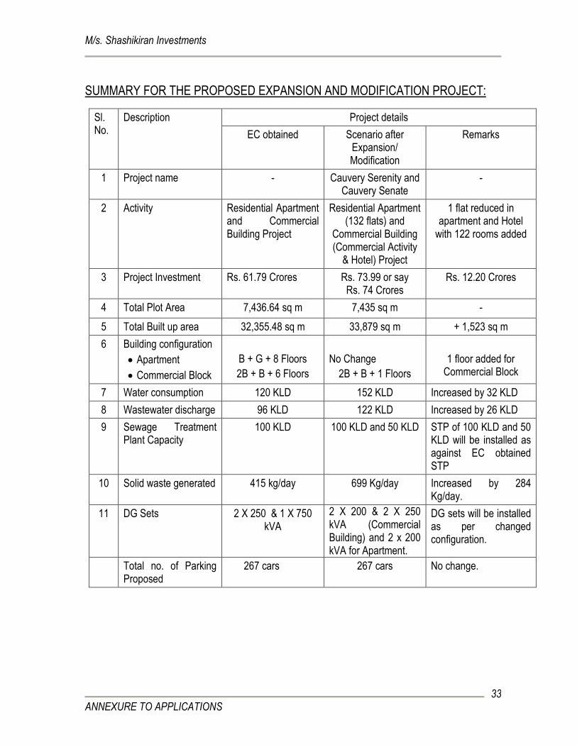
SUMMARY FOR THE PROPOSED EXPANSION AND MODIFICATION PROJECT:
Sl. No.
Description Project details
EC obtained Scenario after Expansion/ Modification
Remarks
1 Project name - Cauvery Serenity and Cauvery Senate
-
2 Activity Residential Apartment and Commercial Building Project
Residential Apartment (132 flats) and
Commercial Building (Commercial Activity
& Hotel) Project
1 flat reduced in apartment and Hotel
with 122 rooms added
3 Project Investment Rs. 61.79 Crores Rs. 73.99 or say Rs. 74 Crores
Rs. 12.20 Crores
4 Total Plot Area 7,436.64 sq m 7,435 sq m -
5 Total Built up area 32,355.48 sq m 33,879 sq m + 1,523 sq m
6 Building configuration
Apartment
Commercial Block
B + G + 8 Floors
2B + B + 6 Floors
No Change
2B + B + 1 Floors
1 floor added for Commercial Block
7 Water consumption 120 KLD 152 KLD Increased by 32 KLD
8 Wastewater discharge 96 KLD 122 KLD Increased by 26 KLD
9 Sewage Treatment Plant Capacity
100 KLD 100 KLD and 50 KLD STP of 100 KLD and 50 KLD will be installed as against EC obtained STP
10 Solid waste generated 415 kg/day 699 Kg/day Increased by 284 Kg/day.
11 DG Sets 2 X 250 & 1 X 750 kVA
2 X 200 & 2 X 250 kVA (Commercial Building) and 2 x 200 kVA for Apartment.
DG sets will be installed as per changed configuration.
Total no. of Parking Proposed
267 cars 267 cars No change.
M/s. Shashikiran Investments
ANNEXURE TO APPLICATIONS
34
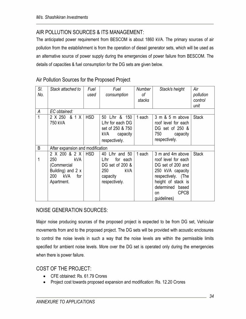
AIR POLLUTION SOURCES & ITS MANAGEMENT:
The anticipated power requirement from BESCOM is about 1860 kVA. The primary sources of air
pollution from the establishment is from the operation of diesel generator sets, which will be used as
an alternative source of power supply during the emergencies of power failure from BESCOM. The
details of capacities & fuel consumption for the DG sets are given below.
Air Pollution Sources for the Proposed Project
SI. No.
Stack attached to Fuel used
Fuel consumption
Number of
stacks
Stack/s height Air pollution control unit
A EC obtained:
1 2 X 250 & 1 X 750 kVA
HSD 50 L/hr & 150 L/hr for each DG set of 250 & 750 kVA capacity
respectively.
1 each 3 m & 5 m above roof level for each DG set of 250 & 750 capacity respectively.
Stack
B After expansion and modification
1 11
2 X 200 & 2 X 250 kVA (Commercial Building) and 2 x 200 kVA for Apartment.
HSD 40 L/hr and 50 L/hr for each DG set of 200 & 250 kVA capacity respectively.
1 each 3 m and 4m above roof level for each DG set of 200 and 250 kVA capacity respectively. (The height of stack is determined based on CPCB guidelines)
Stack
NOISE GENERATION SOURCES: Major noise producing sources of the proposed project is expected to be from DG set, Vehicular
movements from and to the proposed project. The DG sets will be provided with acoustic enclosures
to control the noise levels in such a way that the noise levels are within the permissible limits
specified for ambient noise levels. More over the DG set is operated only during the emergencies
when there is power failure.
COST OF THE PROJECT:
CFE obtained: Rs. 61.79 Crores
Project cost towards proposed expansion and modification: Rs. 12.20 Crores
M/s. Shashikiran Investments
ANNEXURE TO APPLICATIONS
35
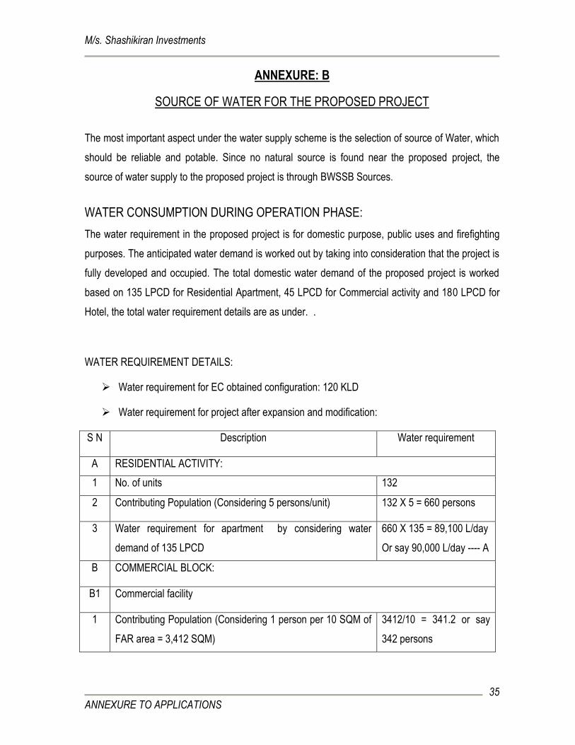
ANNEXURE: B
SOURCE OF WATER FOR THE PROPOSED PROJECT
The most important aspect under the water supply scheme is the selection of source of Water, which
should be reliable and potable. Since no natural source is found near the proposed project, the
source of water supply to the proposed project is through BWSSB Sources.
WATER CONSUMPTION DURING OPERATION PHASE:
The water requirement in the proposed project is for domestic purpose, public uses and firefighting
purposes. The anticipated water demand is worked out by taking into consideration that the project is
fully developed and occupied. The total domestic water demand of the proposed project is worked
based on 135 LPCD for Residential Apartment, 45 LPCD for Commercial activity and 180 LPCD for
Hotel, the total water requirement details are as under. .
WATER REQUIREMENT DETAILS:
Water requirement for EC obtained configuration: 120 KLD
Water requirement for project after expansion and modification:
S N Description Water requirement
A RESIDENTIAL ACTIVITY:
1 No. of units 132
2 Contributing Population (Considering 5 persons/unit) 132 X 5 = 660 persons
3 Water requirement for apartment by considering water
demand of 135 LPCD
660 X 135 = 89,100 L/day
Or say 90,000 L/day ---- A
B COMMERCIAL BLOCK:
B1 Commercial facility
1 Contributing Population (Considering 1 person per 10 SQM of
FAR area = 3,412 SQM)
3412/10 = 341.2 or say
342 persons
M/s. Shashikiran Investments
ANNEXURE TO APPLICATIONS
36
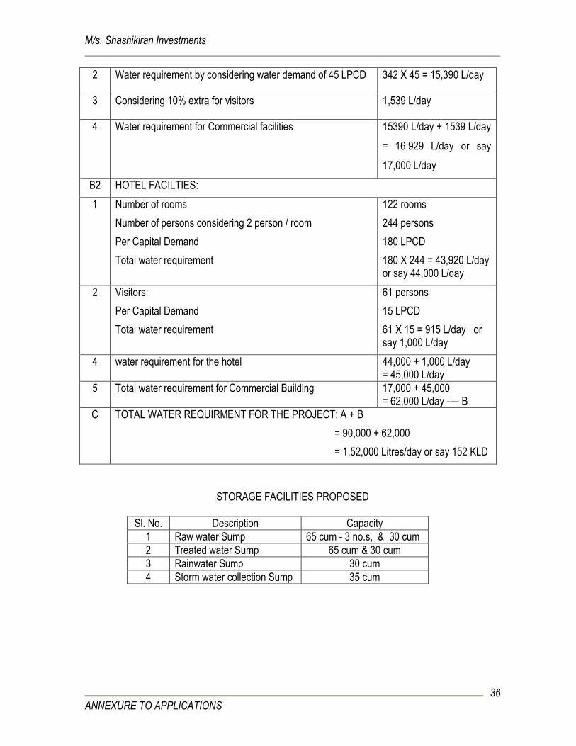
2 Water requirement by considering water demand of 45 LPCD 342 X 45 = 15,390 L/day
3 Considering 10% extra for visitors 1,539 L/day
4 Water requirement for Commercial facilities 15390 L/day + 1539 L/day
= 16,929 L/day or say
17,000 L/day
B2 HOTEL FACILTIES:
1 Number of rooms
Number of persons considering 2 person / room
Per Capital Demand
Total water requirement
122 rooms
244 persons
180 LPCD
180 X 244 = 43,920 L/day or say 44,000 L/day
2 Visitors:
Per Capital Demand
Total water requirement
61 persons
15 LPCD
61 X 15 = 915 L/day or say 1,000 L/day
4 water requirement for the hotel 44,000 + 1,000 L/day = 45,000 L/day
5 Total water requirement for Commercial Building 17,000 + 45,000 = 62,000 L/day ---- B
C TOTAL WATER REQUIRMENT FOR THE PROJECT: A + B
= 90,000 + 62,000
= 1,52,000 Litres/day or say 152 KLD
STORAGE FACILITIES PROPOSED
Sl. No. Description Capacity
1 Raw water Sump 65 cum - 3 no.s, & 30 cum
2 Treated water Sump 65 cum & 30 cum
3 Rainwater Sump 30 cum
4 Storm water collection Sump 35 cum
M/s. Shashikiran Investments
ANNEXURE TO APPLICATIONS
37
ANNEXURE: C
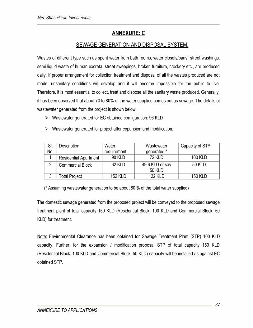
SEWAGE GENERATION AND DISPOSAL SYSTEM:
Wastes of different type such as spent water from bath rooms, water closets/pans, street washings,
semi liquid waste of human excreta, street sweepings, broken furniture, crockery etc., are produced
daily. If proper arrangement for collection treatment and disposal of all the wastes produced are not
made, unsanitary conditions will develop and it will become impossible for the public to live.
Therefore, it is most essential to collect, treat and dispose all the sanitary waste produced. Generally,
it has been observed that about 70 to 80% of the water supplied comes out as sewage. The details of
wastewater generated from the project is shown below
Wastewater generated for EC obtained configuration: 96 KLD
Wastewater generated for project after expansion and modification:
Sl. No.
Description Water requirement
Wastewater generated *
Capacity of STP
1 Residential Apartment 90 KLD 72 KLD 100 KLD
2 Commercial Block 62 KLD 49.6 KLD or say 50 KLD
50 KLD
3 Total Project 152 KLD 122 KLD 150 KLD
(* Assuming wastewater generation to be about 80 % of the total water supplied)
The domestic sewage generated from the proposed project will be conveyed to the proposed sewage
treatment plant of total capacity 150 KLD (Residential Block: 100 KLD and Commercial Block: 50
KLD) for treatment.
Note: Environmental Clearance has been obtained for Sewage Treatment Plant (STP) 100 KLD
capacity. Further, for the expansion / modification proposal STP of total capacity 150 KLD
(Residential Block: 100 KLD and Commercial Block: 50 KLD) capacity will be installed as against EC
obtained STP.
M/s. Shashikiran Investments
ANNEXURE TO APPLICATIONS
38
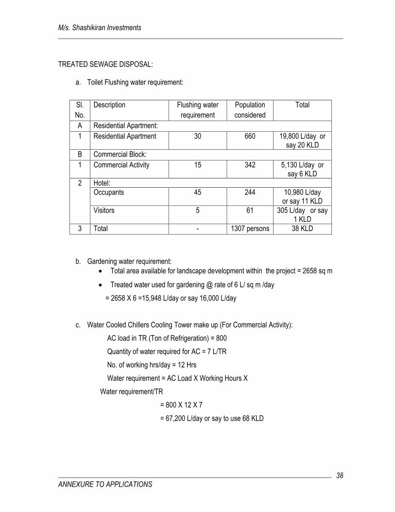
TREATED SEWAGE DISPOSAL:
a. Toilet Flushing water requirement:
Sl.
No.
Description Flushing water
requirement
Population
considered
Total
A Residential Apartment:
1 Residential Apartment 30 660 19,800 L/day or say 20 KLD
B Commercial Block:
1 Commercial Activity 15 342 5,130 L/day or say 6 KLD
2 Hotel:
Occupants 45 244 10,980 L/day or say 11 KLD
Visitors 5 61 305 L/day or say 1 KLD
3 Total - 1307 persons 38 KLD
b. Gardening water requirement:
Total area available for landscape development within the project = 2658 sq m
Treated water used for gardening @ rate of 6 L/ sq m /day
= 2658 X 6 =15,948 L/day or say 16,000 L/day
c. Water Cooled Chillers Cooling Tower make up (For Commercial Activity):
AC load in TR (Ton of Refrigeration) = 800
Quantity of water required for AC = 7 L/TR
No. of working hrs/day = 12 Hrs
Water requirement = AC Load X Working Hours X
Water requirement/TR
= 800 X 12 X 7
= 67,200 L/day or say to use 68 KLD
M/s. Shashikiran Investments
ANNEXURE TO APPLICATIONS
39
The wastewater generated from the project is about 1, 22,000 L/day out of which 38,000 L/day
will be used for toilet flushing, 16,000 L/day will be used for landscape development and 68,000
L/day will be used as AC cooling tower make up water.
TECHNICAL PROPOSAL FOR SEWAGE TREATMENT PLANT (STP)
Wastewater generated from the project will be treated in STP of total capacity 150 KLD. STP of 100
KLD is proposed to treat the sewage from Residential Development and 50 KLD STP is proposed to
treat sewage generated from Commercial Development (Hotel and Commercial Activity). The
wastewater treated to Urban Reuse Standards will be used of Toilet Flushing, Landscape
development and AC cooling tower makeup.
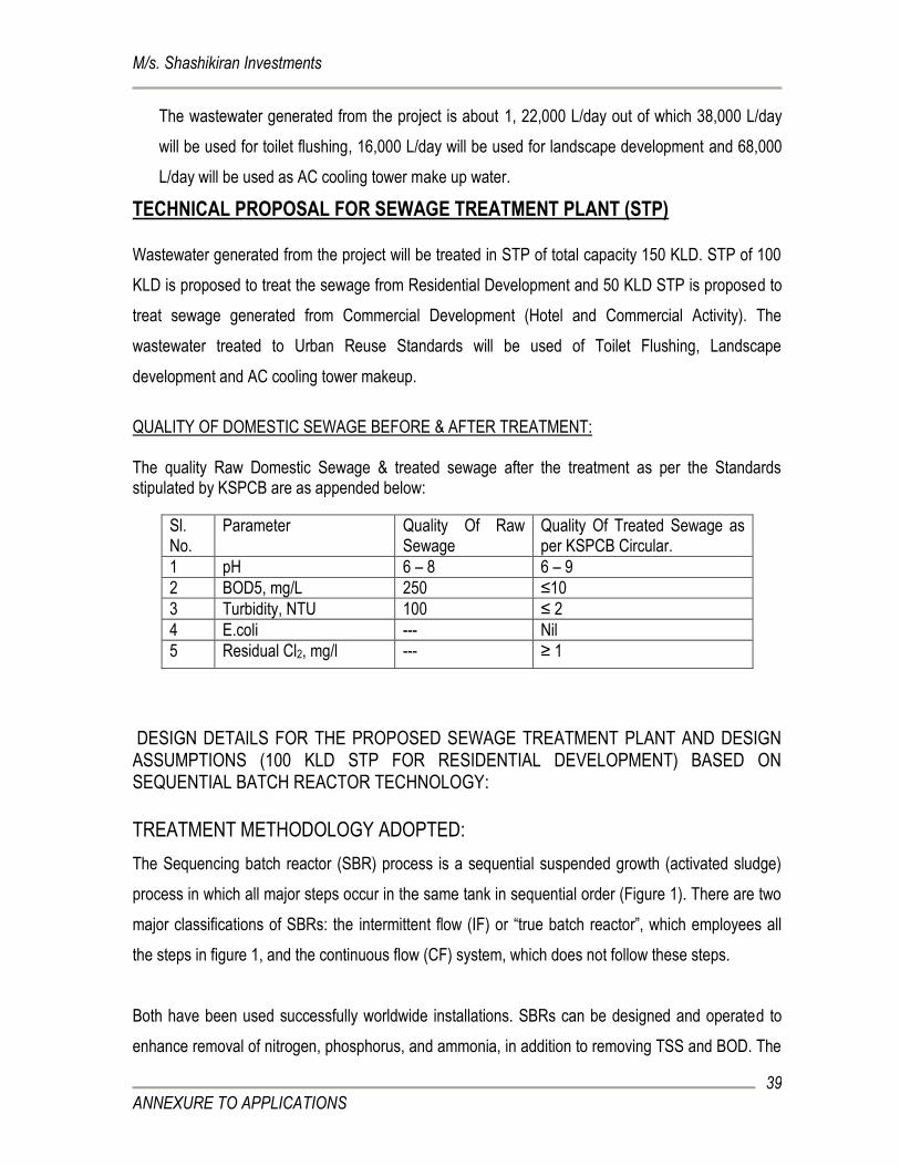
QUALITY OF DOMESTIC SEWAGE BEFORE & AFTER TREATMENT: The quality Raw Domestic Sewage & treated sewage after the treatment as per the Standards stipulated by KSPCB are as appended below:
DESIGN DETAILS FOR THE PROPOSED SEWAGE TREATMENT PLANT AND DESIGN ASSUMPTIONS (100 KLD STP FOR RESIDENTIAL DEVELOPMENT) BASED ON SEQUENTIAL BATCH REACTOR TECHNOLOGY:
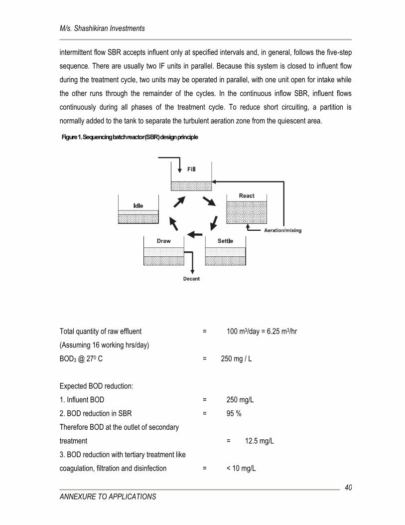
TREATMENT METHODOLOGY ADOPTED:
The Sequencing batch reactor (SBR) process is a sequential suspended growth (activated sludge)
process in which all major steps occur in the same tank in sequential order (Figure 1). There are two
major classifications of SBRs: the intermittent flow (IF) or “true batch reactor”, which employees all
the steps in figure 1, and the continuous flow (CF) system, which does not follow these steps.
Both have been used successfully worldwide installations. SBRs can be designed and operated to
enhance removal of nitrogen, phosphorus, and ammonia, in addition to removing TSS and BOD. The
Sl. No.
Parameter Quality Of Raw Sewage
Quality Of Treated Sewage as per KSPCB Circular.
1 pH 6 – 8 6 – 9
2 BOD5, mg/L 250 ≤10
3 Turbidity, NTU 100 ≤ 2
4 E.coli --- Nil
5 Residual Cl2, mg/l --- ≥ 1
M/s. Shashikiran Investments
ANNEXURE TO APPLICATIONS
40
intermittent flow SBR accepts influent only at specified intervals and, in general, follows the five-step
sequence. There are usually two IF units in parallel. Because this system is closed to influent flow
during the treatment cycle, two units may be operated in parallel, with one unit open for intake while
the other runs through the remainder of the cycles. In the continuous inflow SBR, influent flows
continuously during all phases of the treatment cycle. To reduce short circuiting, a partition is
normally added to the tank to separate the turbulent aeration zone from the quiescent area.
Total quantity of raw effluent = 100 m3/day = 6.25 m3/hr
(Assuming 16 working hrs/day)
BOD3 @ 270 C = 250 mg / L
Expected BOD reduction:
1. Influent BOD = 250 mg/L
2. BOD reduction in SBR = 95 %
Therefore BOD at the outlet of secondary
treatment = 12.5 mg/L
3. BOD reduction with tertiary treatment like
coagulation, filtration and disinfection = < 10 mg/L
M/s. Shashikiran Investments
ANNEXURE TO APPLICATIONS
41
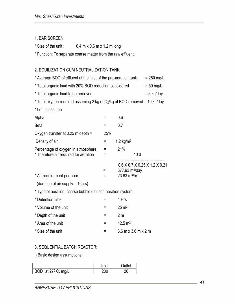
1. BAR SCREEN:
* Size of the unit : 0.4 m x 0.6 m x 1.2 m long
* Function: To separate coarse matter from the raw effluent.
2. EQUILIZATION CUM NEUTRALIZATION TANK:
* Average BOD of effluent at the inlet of the pre-aeration tank = 250 mg/L
* Total organic load with 20% BOD reduction considered = 50 mg/L
* Total organic load to be removed = 5 kg/day
* Total oxygen required assuming 2 kg of O2/kg of BOD removed = 10 kg/day
* Let us assume
Alpha = 0.6
Beta = 0.7
Oxygen transfer at 0.25 m depth = 25%
Density of air = 1.2 kg/m3
Percentage of oxygen in atmosphere = 21% * Therefore air required for aeration = 10.0
---------------------------------- 0.6 X 0.7 X 0.25 X 1.2 X 0.21
= 377.93 m3/day * Air requirement per hour = 23.63 m3/hr
(duration of air supply = 16hrs)
* Type of aeration: coarse bubble diffused aeration system
* Detention time = 4 Hrs
* Volume of the unit = 25 m3
* Depth of the unit = 2 m
* Area of the unit = 12.5 m2
* Size of the unit = 3.6 m x 3.6 m x 2 m
3. SEQUENTIAL BATCH REACTOR:
i) Basic design assumptions
Inlet Outlet
BOD3 at 270 C, mg/L 200 20
M/s. Shashikiran Investments
ANNEXURE TO APPLICATIONS
42
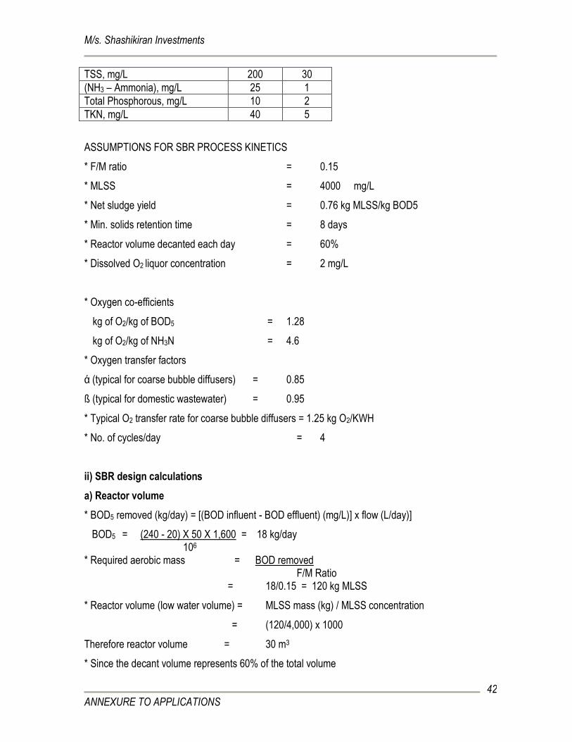
ASSUMPTIONS FOR SBR PROCESS KINETICS
* F/M ratio = 0.15
* MLSS = 4000 mg/L
* Net sludge yield = 0.76 kg MLSS/kg BOD5
* Min. solids retention time = 8 days
* Reactor volume decanted each day = 60%
* Dissolved O2 liquor concentration = 2 mg/L
* Oxygen co-efficients
kg of O2/kg of BOD5 = 1.28
kg of O2/kg of NH3N = 4.6
* Oxygen transfer factors
ά (typical for coarse bubble diffusers) = 0.85
ß (typical for domestic wastewater) = 0.95
* Typical O2 transfer rate for coarse bubble diffusers = 1.25 kg O2/KWH
* No. of cycles/day = 4
ii) SBR design calculations
a) Reactor volume
* BOD5 removed (kg/day) = [(BOD influent - BOD effluent) (mg/L)] x flow (L/day)]
BOD5 = (240 - 20) X 50 X 1,600 = 18 kg/day 106
* Required aerobic mass = BOD removed F/M Ratio
= 18/0.15 = 120 kg MLSS
* Reactor volume (low water volume) = MLSS mass (kg) / MLSS concentration
= (120/4,000) x 1000
Therefore reactor volume = 30 m3
* Since the decant volume represents 60% of the total volume
TSS, mg/L 200 30
(NH3 – Ammonia), mg/L 25 1
Total Phosphorous, mg/L 10 2
TKN, mg/L 40 5
M/s. Shashikiran Investments
ANNEXURE TO APPLICATIONS
43
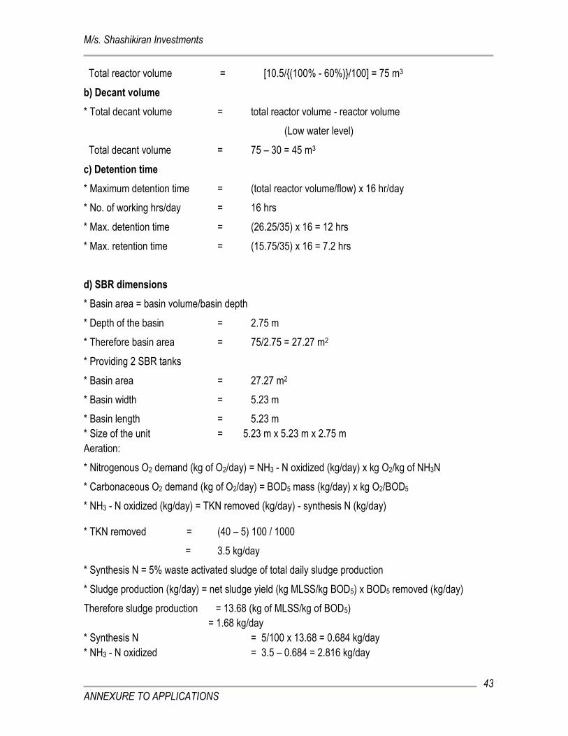
Total reactor volume = [10.5/{(100% - 60%)}/100] = 75 m3
b) Decant volume
* Total decant volume = total reactor volume - reactor volume
(Low water level)
Total decant volume = 75 – 30 = 45 m3
c) Detention time
* Maximum detention time = (total reactor volume/flow) x 16 hr/day
* No. of working hrs/day = 16 hrs
* Max. detention time = (26.25/35) x 16 = 12 hrs
* Max. retention time = (15.75/35) x 16 = 7.2 hrs
d) SBR dimensions
* Basin area = basin volume/basin depth
* Depth of the basin = 2.75 m
* Therefore basin area = 75/2.75 = 27.27 m2
* Providing 2 SBR tanks
* Basin area = 27.27 m2
* Basin width = 5.23 m
* Basin length = 5.23 m
* Size of the unit = 5.23 m x 5.23 m x 2.75 m
Aeration:
* Nitrogenous O2 demand (kg of O2/day) = NH3 - N oxidized (kg/day) x kg O2/kg of NH3N
* Carbonaceous O2 demand (kg of O2/day) = BOD5 mass (kg/day) x kg O2/BOD5
* NH3 - N oxidized (kg/day) = TKN removed (kg/day) - synthesis N (kg/day) * TKN removed = (40 – 5) 100 / 1000
= 3.5 kg/day
* Synthesis N = 5% waste activated sludge of total daily sludge production
* Sludge production (kg/day) = net sludge yield (kg MLSS/kg BOD5) x BOD5 removed (kg/day)
Therefore sludge production = 13.68 (kg of MLSS/kg of BOD5)
= 1.68 kg/day
* Synthesis N = 5/100 x 13.68 = 0.684 kg/day
* NH3 - N oxidized = 3.5 – 0.684 = 2.816 kg/day
M/s. Shashikiran Investments
ANNEXURE TO APPLICATIONS
44
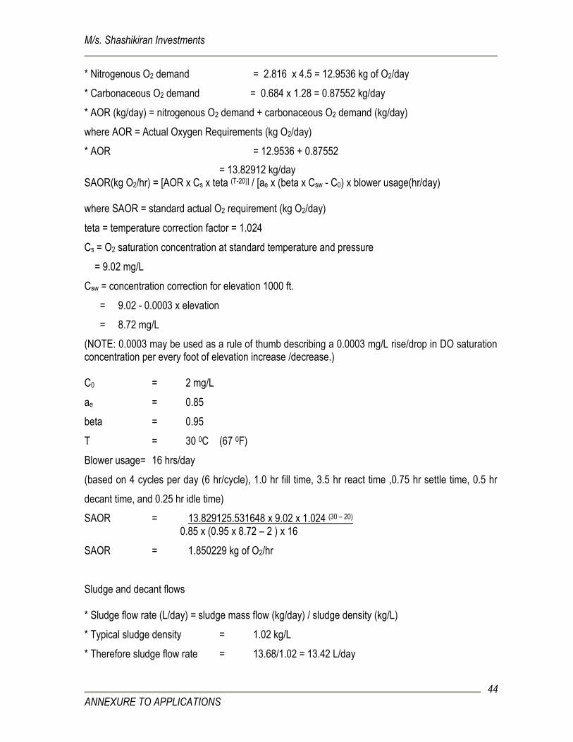
* Nitrogenous O2 demand = 2.816 x 4.5 = 12.9536 kg of O2/day
* Carbonaceous O2 demand = 0.684 x 1.28 = 0.87552 kg/day
* AOR (kg/day) = nitrogenous O2 demand + carbonaceous O2 demand (kg/day)
where AOR = Actual Oxygen Requirements (kg O2/day)
* AOR = 12.9536 + 0.87552
= 13.82912 kg/day SAOR(kg O2/hr) = [AOR x Cs x teta (T-20)] / [ae x (beta x Csw - C0) x blower usage(hr/day) where SAOR = standard actual O2 requirement (kg O2/day)
teta = temperature correction factor = 1.024
Cs = O2 saturation concentration at standard temperature and pressure
= 9.02 mg/L
Csw = concentration correction for elevation 1000 ft.
= 9.02 - 0.0003 x elevation
= 8.72 mg/L
(NOTE: 0.0003 may be used as a rule of thumb describing a 0.0003 mg/L rise/drop in DO saturation concentration per every foot of elevation increase /decrease.) C0 = 2 mg/L
ae = 0.85
beta = 0.95
T = 30 0C (67 0F)
Blower usage= 16 hrs/day
(based on 4 cycles per day (6 hr/cycle), 1.0 hr fill time, 3.5 hr react time ,0.75 hr settle time, 0.5 hr
decant time, and 0.25 hr idle time)
SAOR = 13.829125.531648 x 9.02 x 1.024 (30 – 20)
0.85 x (0.95 x 8.72 – 2 ) x 16
SAOR = 1.850229 kg of O2/hr
Sludge and decant flows * Sludge flow rate (L/day) = sludge mass flow (kg/day) / sludge density (kg/L)
* Typical sludge density = 1.02 kg/L
* Therefore sludge flow rate = 13.68/1.02 = 13.42 L/day
M/s. Shashikiran Investments
ANNEXURE TO APPLICATIONS
45
4. SLUDGE RECYCLE PUMP:
* Volume of sludge = 30 m3/day
* Assuming the sludge recycle pump works for 16 hrs/day
* Discharge rate = 3.75 m3/Hr @ 10 – 12 m head
* Function: To re-circulate the return sludge to aeration tank to maintain the required MLSS and
transfer excess sludge to Plate & Frame Filter Press.
5. SLUDGE HOLDING TANK:
* Anticipated quantity of the secondary
sludge from the STP = 30000 L/day = 2 m3/day
* Depth of the digester = 1.5 m
* Area of digester = 3.0 m2
* Diameter = 1.95 m
* Size of the aerobic digester required = 1.95 m dia X 2 m depth
(Considering a free board of 0.5 m)
However for practical purposes sludge holding tank of 1.2 m dia X 2 m depth (0.5 m free- board) is
proposed.
6. SCREW PUMP:
* Pumping rate = 2.5 m3/hr
* Pumping head = 16 – 18 m
7. MECHANICAL FILTER PRESS:
* Assumed type of sludge: Secondary Biological
* Let the concentration of solids be = 1%
* Specific gravity of the solids = 1.2
* Density of water = 1000 kg/m3
* Minimum dry solids allowable
M/s. Shashikiran Investments
ANNEXURE TO APPLICATIONS
46
in the sludge solid cake = 25-30% = 30%
Sludge Cake Characteristics * Cake thickness = 32 mm
* Wet cake density = 1280 kg/m3
Operating Time: 10 Hrs/day; 6 days/week
Cycle Time
* Feed : 20 Minutes
*Compression : 15 Minutes
* Cake Discharge: 25 Minutes
* Total : 60 Minutes
* Design liquid sludge flow = 3000 L/day
* Daily solid sludge generation rate = 24 kg/day
* Quantity of sludge solids load on the filter press = 120 kg/5 days
* Assume sludge holding capacity = 40 kg/m2
* Size of the filter press required = 3 m2
* Let the size of each plate = 0.47 m × 0.47 m
= 0.22 m2
* Number of such chambers required = 3/0.22 = 13.58
Or say 14 no.
8. FILTER FEED PUMP:
* Pumping rate = 2.5 m3/hr
* Pumping Head = 16 – 18 m
* Type of pump: Horizontal centrifugal with CI pen impeller self priming type coupled to motor of
required speed with B Class insulation and IP 55 protection hood.
* Function: To pump the clarified sewage through Pressure Sand and Carbon Filters.
9. PRESSURE SAND AND CARBON FILTER:
* Total Flow = 100 m3/day
M/s. Shashikiran Investments
ANNEXURE TO APPLICATIONS
47
* Duration of pumping considered = 10 hr/day
* Pumping rate = 10 m3/hr
* Surface loading considered = 10 m3/m2/hr
* Area of the filter = 1 m2
* Diameter of the filter = 1.13 m
* Number of sand filters = 1
* Number of carbon filters = 1
* Height of the shell = 1.5 m
10. CHLORINE DOSER: Provide Milton Roy Asia LMI/Prominent make metering pump of dosing capacity 4–6 LPH with 100
liters capacity dosing tank.
11. COMMON TREATED WATER SUMP:
* Depth = 3 m
* Detention time = 12 hrs
* Volume of the unit = 26.38 m3
* Area = 15 m2
* Size of the unit = 2.9 m × 2.9 m × 3 m
* Air required = 22.5 m3/hr
12. COMMON TREATED WATER TRANSFER PUMP:
* Volume of treated water = 100 m3/day
* Discharge rate = 6.25 m3/Hr @ 10 – 12 m head
*Function: To pump the treated water from the treated water collection sump to garden and also for
toilet flushing to over head tank.
13. BLOWER CAPACITY: * Blower capacity required = Equalization tank + SBR + 10% extra
= 23.63 + 1.8502 + 10%
= 25.48023 + 2.548
M/s. Shashikiran Investments
ANNEXURE TO APPLICATIONS
48
= 28.0282 m3/hr or say 29 m3/hr Note: The capacity of common twin lobe roots air blower suitable to discharge about 10 m3/hr @
0.5 KSC – 2 No.s (1 W + 1 SB). The common blower shall supply the air required for the aeration
system (aeration tank & aerobic digester) and other primary, intermittent and final storage units of the
treatment plant (equalization tank, pre-filtration and filtered water tank).
13. INTER PLANT PIPING:
Provide PVC pipes of 4 - 6 ksc pressure rating including necessary specials like tee’s, bends,
elbows, flanges etc.
14. ELECTRICALS:
Provide and install motor control center with necessary cabling, earthing etc. complete.
Design details summery for STP
Ref. no. Particulars Size
1 Bar Screen 0.4 x 0.6 x 1.2 m
2 Equalization cum neutralization Tank 3.6 x 3.6 x 2 m
3 SBR (2 no.s) 5.23 x 5.23 x 2.75 m
5 Mechanical filter press 14 chambers – 0.61 x 0.61 m
7 Pressure Sand and Carbon Filter - 1 each 1.13 m dia
SCHEMATIC FLOW CHART
Raw Sewage
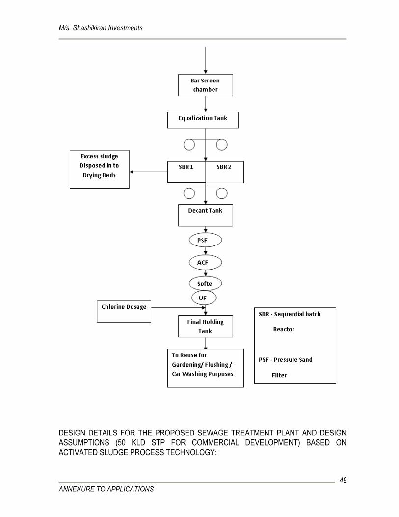
M/s. Shashikiran Investments
ANNEXURE TO APPLICATIONS
49
DESIGN DETAILS FOR THE PROPOSED SEWAGE TREATMENT PLANT AND DESIGN ASSUMPTIONS (50 KLD STP FOR COMMERCIAL DEVELOPMENT) BASED ON ACTIVATED SLUDGE PROCESS TECHNOLOGY:
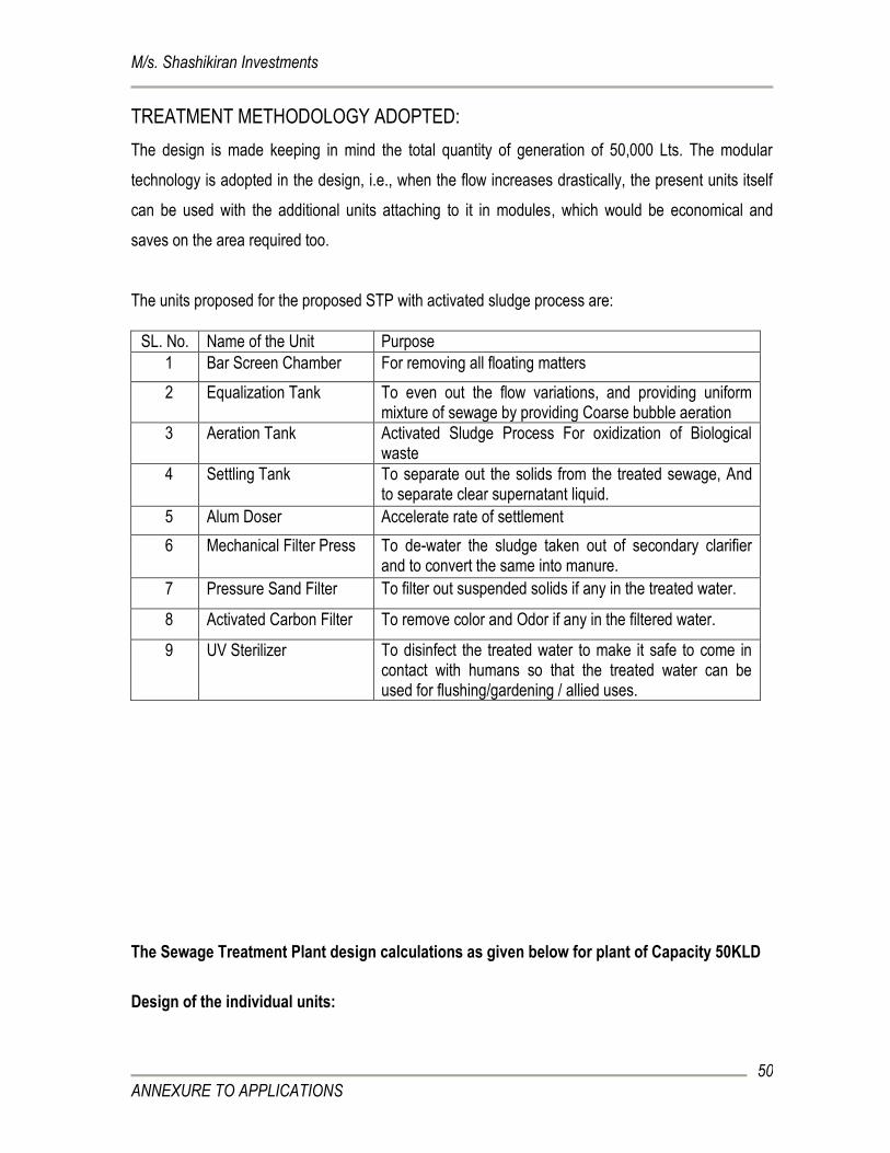
M/s. Shashikiran Investments
ANNEXURE TO APPLICATIONS
50
TREATMENT METHODOLOGY ADOPTED:
The design is made keeping in mind the total quantity of generation of 50,000 Lts. The modular
technology is adopted in the design, i.e., when the flow increases drastically, the present units itself
can be used with the additional units attaching to it in modules, which would be economical and
saves on the area required too.
The units proposed for the proposed STP with activated sludge process are:
SL. No. Name of the Unit Purpose
1 Bar Screen Chamber For removing all floating matters
2 Equalization Tank To even out the flow variations, and providing uniform mixture of sewage by providing Coarse bubble aeration
3 Aeration Tank Activated Sludge Process For oxidization of Biological waste
4 Settling Tank To separate out the solids from the treated sewage, And to separate clear supernatant liquid.
5 Alum Doser Accelerate rate of settlement
6 Mechanical Filter Press To de-water the sludge taken out of secondary clarifier and to convert the same into manure.
7 Pressure Sand Filter To filter out suspended solids if any in the treated water.
8 Activated Carbon Filter To remove color and Odor if any in the filtered water.
9 UV Sterilizer To disinfect the treated water to make it safe to come in contact with humans so that the treated water can be used for flushing/gardening / allied uses.
The Sewage Treatment Plant design calculations as given below for plant of Capacity 50KLD
Design of the individual units:
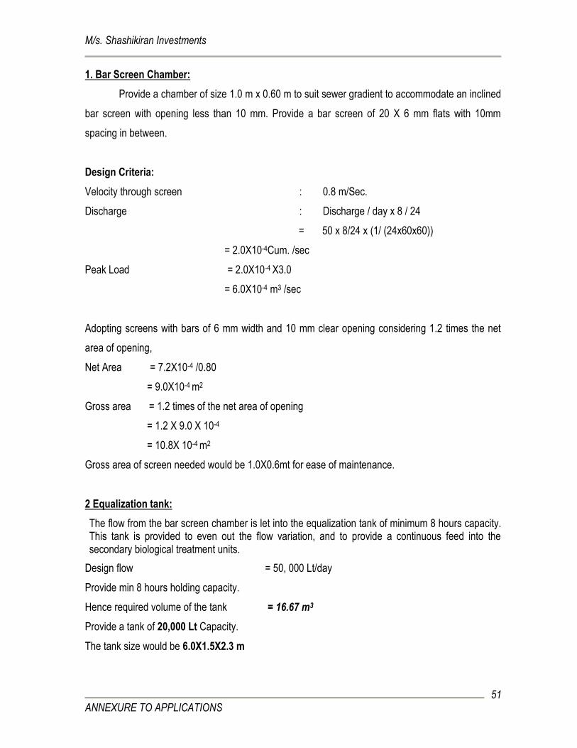
M/s. Shashikiran Investments
ANNEXURE TO APPLICATIONS
51
1. Bar Screen Chamber:
Provide a chamber of size 1.0 m x 0.60 m to suit sewer gradient to accommodate an inclined
bar screen with opening less than 10 mm. Provide a bar screen of 20 X 6 mm flats with 10mm
spacing in between.
Design Criteria:
Velocity through screen : 0.8 m/Sec.
Discharge : Discharge / day x 8 / 24
= 50 x 8/24 x (1/ (24x60x60))
= 2.0X10⁻⁴Cum. /sec
Peak Load = 2.0X10-4 X3.0
= 6.0X10⁻⁴ m3 /sec
Adopting screens with bars of 6 mm width and 10 mm clear opening considering 1.2 times the net
area of opening,
Net Area = 7.2X10⁻⁴ /0.80
= 9.0X10⁻⁴ m2
Gross area = 1.2 times of the net area of opening
= 1.2 X 9.0 X 10-4
= 10.8X 10⁻⁴ m2
Gross area of screen needed would be 1.0X0.6mt for ease of maintenance.
2 Equalization tank:
The flow from the bar screen chamber is let into the equalization tank of minimum 8 hours capacity. This tank is provided to even out the flow variation, and to provide a continuous feed into the secondary biological treatment units.
Design flow = 50, 000 Lt/day
Provide min 8 hours holding capacity.
Hence required volume of the tank = 16.67 m3
Provide a tank of 20,000 Lt Capacity.
The tank size would be 6.0X1.5X2.3 m
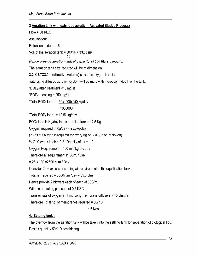
M/s. Shashikiran Investments
ANNEXURE TO APPLICATIONS
52
3 Aeration tank with extended aeration (Activated Sludge Process)
Flow = 50 KLD.
Assumption:
Retention period = 16hrs
Vol. of the aeration tank = 50X16 = 33.33 m3 24
Hence provide aeration tank of capacity 35,000 liters capacity.
The aeration tank size required will be of dimension
3.2 X 3.7X3.0m (effective volume) since the oxygen transfer
rate using diffused aeration system will be more with increase in depth of the tank.
"BOD5 after treatment <10 mg/lit
"BOD5 Loading = 250 mg/lit
"Total BOD5 load = 50x1000x250 kg/day
1000000
"Total BOD5 load = 12.50 kg/day
BOD5 load in Kg/day in the aeration tank = 12.5 Kg
Oxygen required in Kg/day = 25.0kg/day
(2 kgs of Oxygen is required for every Kg of BOD5 to be removed)
% Of Oxygen in air = 0.21 Density of air = 1.2
Oxygen Requirement = 100 m3 / kg 02 / day
Therefore air requirement in Cum. / Day
= 25 x 100 =2500 cum / Day.
Consider 20% excess assuming air requirement in the equalization tank.
Total air required = 3000cum /day = 59.0 cfm
Hence provide 2 blowers each of each of 30Cfm.
With an operating pressure of 0.5 KSC.
Transfer rate of oxygen in 1 mt. Long membrane diffusers = 10 cfm /hr.
Therefore Total no. of membranes required = 60/ 10
= 6 Nos.
4. Settling tank :
The overflow from the aeration tank will be taken into the settling tank for separation of biological floc.
Design quantity 50KLD considering.
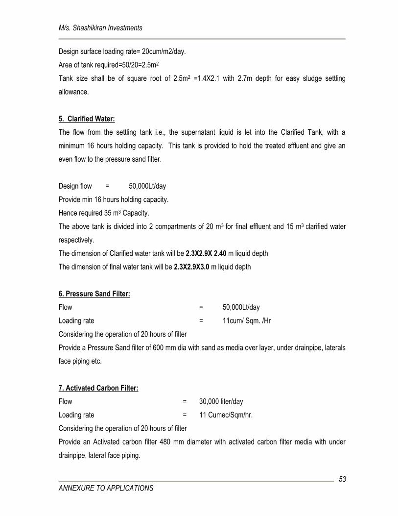
M/s. Shashikiran Investments
ANNEXURE TO APPLICATIONS
53
Design surface loading rate= 20cum/m2/day.
Area of tank required=50/20=2.5m2
Tank size shall be of square root of 2.5m2 =1.4X2.1 with 2.7m depth for easy sludge settling
allowance.
5. Clarified Water:
The flow from the settling tank i.e., the supernatant liquid is let into the Clarified Tank, with a
minimum 16 hours holding capacity. This tank is provided to hold the treated effluent and give an
even flow to the pressure sand filter.
Design flow = 50,000Lt/day
Provide min 16 hours holding capacity.
Hence required 35 m3 Capacity.
The above tank is divided into 2 compartments of 20 m3 for final effluent and 15 m3 clarified water
respectively.
The dimension of Clarified water tank will be 2.3X2.9X 2.40 m liquid depth
The dimension of final water tank will be 2.3X2.9X3.0 m liquid depth
6. Pressure Sand Filter:
Flow = 50,000Lt/day
Loading rate = 11cum/ Sqm. /Hr
Considering the operation of 20 hours of filter
Provide a Pressure Sand filter of 600 mm dia with sand as media over layer, under drainpipe, laterals
face piping etc.
7. Activated Carbon Filter:
Flow = 30,000 liter/day
Loading rate = 11 Cumec/Sqm/hr.
Considering the operation of 20 hours of filter
Provide an Activated carbon filter 480 mm diameter with activated carbon filter media with under
drainpipe, lateral face piping.
M/s. Shashikiran Investments
ANNEXURE TO APPLICATIONS
54
8. U.V. STERILISATION:
The filtered water is passed through an U.V. filter for disinfection. One number of U.V. Sterilizer is
provided for this purpose.
9. Pumps
a. Provide 2 Nos. sewage transfer pumps (one working and one standby)
Capacity : 3.5 KLH @ 15m head
Type : Open impeller non-clog centrifugal pumps
Solid handling size : Up to 25 mm
Duty: To pump the sewage from the Equalization tank to the Aeration Tank.
b. Provide 2 Nos Sludge transfer
Capacity : 1.0 KLH/hr @ 15 m head
Type : Open impeller non-clog centrifugal Pumps
Solid handling size: Up to 25 mm
Duty: To pump the sludge from the Clarifloculator to the Sludge Holding Tank.
C. Provide 2 No’s Filter feed pumps
Capacity : 3.5KLH @ 30 m head
Type : Open impeller non-clog centrifugal pumps
Solid handling size : Up to 10 mm
Duty: To pump the Treated effluent from the Clarified Water tank through the Pressure Sand Filter
and Activated Carbon Filter.
10. Filter Press:
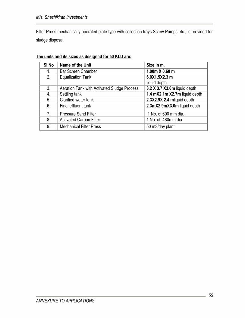
M/s. Shashikiran Investments
ANNEXURE TO APPLICATIONS
55
Filter Press mechanically operated plate type with collection trays Screw Pumps etc., is provided for
sludge disposal.
The units and its sizes as designed for 50 KLD are:
Sl No Name of the Unit Size in m.
1. Bar Screen Chamber 1.00m X 0.60 m
2. Equalization Tank 6.0X1.5X2.3 m liquid depth
3. Aeration Tank with Activated Sludge Process 3.2 X 3.7 X3.0m liquid depth
4. Settling tank 1.4 mX2.1m X2.7m liquid depth
5. Clarified water tank 2.3X2.9X 2.4 mliquid depth
6. Final effluent tank 2.3mX2.9mX3.0m liquid depth
7. Pressure Sand Filter 1 No. of 600 mm dia.
8. Activated Carbon Filter 1 No. of 480mm dia
9. Mechanical Filter Press 50 m3/day plant
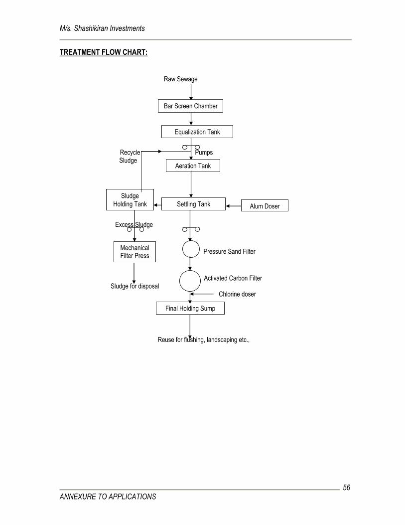
M/s. Shashikiran Investments
ANNEXURE TO APPLICATIONS
56
TREATMENT FLOW CHART:
Raw Sewage
Recycle Pumps Sludge
Excess Sludge
Pressure Sand Filter
Activated Carbon Filter Sludge for disposal Chlorine doser
Reuse for flushing, landscaping etc.,
Bar Screen Chamber
Equalization Tank
Aeration Tank
Settling Tank
Final Holding Sump
Mechanical Filter Press
Alum Doser
Sludge
Holding Tank
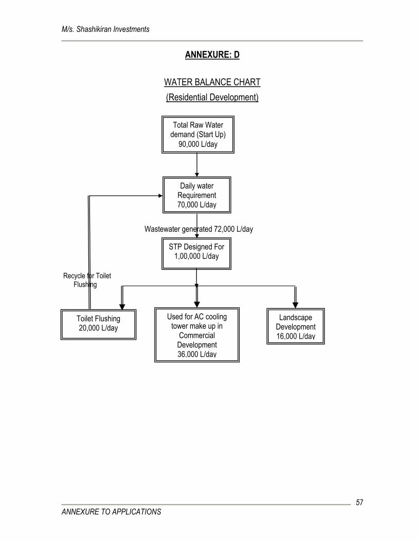
M/s. Shashikiran Investments
ANNEXURE TO APPLICATIONS
57
ANNEXURE: D
WATER BALANCE CHART
(Residential Development)
Wastewater generated 72,000 L/day
Recycle for Toilet Flushing
Daily water Requirement 70,000 L/day
STP Designed For 1,00,000 L/day
Total Raw Water demand (Start Up)
90,000 L/day
Toilet Flushing 20,000 L/day
Landscape Development 16,000 L/day
Used for AC cooling tower make up in
Commercial Development 36,000 L/day
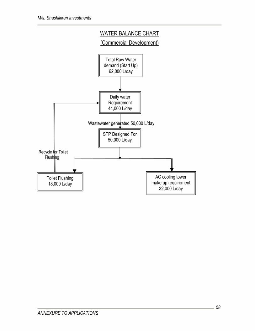
M/s. Shashikiran Investments
ANNEXURE TO APPLICATIONS
58
WATER BALANCE CHART
(Commercial Development)
Wastewater generated 50,000 L/day
Recycle for Toilet Flushing
Daily water Requirement 44,000 L/day
STP Designed For 50,000 L/day
Total Raw Water demand (Start Up)
62,000 L/day
Toilet Flushing 18,000 L/day
AC cooling tower make up requirement
32,000 L/day
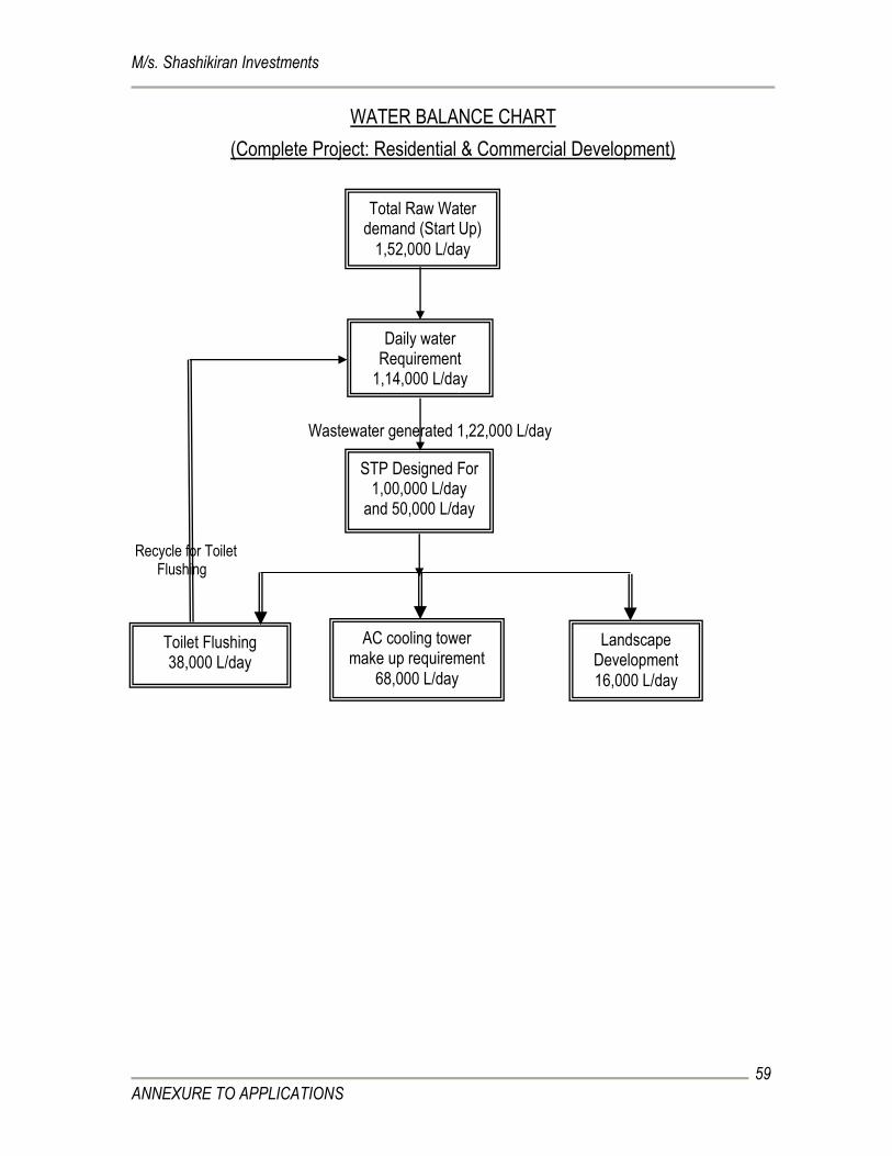
M/s. Shashikiran Investments
ANNEXURE TO APPLICATIONS
59
WATER BALANCE CHART
(Complete Project: Residential & Commercial Development)
Wastewater generated 1,22,000 L/day
Recycle for Toilet Flushing
Daily water Requirement
1,14,000 L/day
STP Designed For 1,00,000 L/day
and 50,000 L/day
Total Raw Water demand (Start Up)
1,52,000 L/day
Toilet Flushing 38,000 L/day
Landscape Development 16,000 L/day
AC cooling tower make up requirement
68,000 L/day
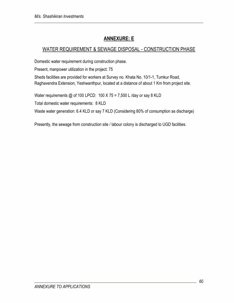
M/s. Shashikiran Investments
ANNEXURE TO APPLICATIONS
60
ANNEXURE: E
WATER REQUIREMENT & SEWAGE DISPOSAL - CONSTRUCTION PHASE
Domestic water requirement during construction phase.
Present, manpower utilization in the project: 75
Sheds facilities are provided for workers at Survey no. Khata No. 10/1-1, Tumkur Road,
Raghavendra Extension, Yeshwanthpur, located at a distance of about 1 Km from project site.
Water requirements @ of 100 LPCD: 100 X 75 = 7,500 L /day or say 8 KLD
Total domestic water requirements: 8 KLD
Waste water generation: 6.4 KLD or say 7 KLD (Considering 80% of consumption as discharge)
Presently, the sewage from construction site / labour colony is discharged to UGD facilities.
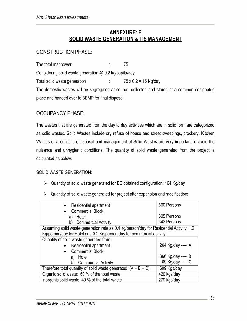
M/s. Shashikiran Investments
ANNEXURE TO APPLICATIONS
61
ANNEXURE: F SOLID WASTE GENERATION & ITS MANAGEMENT
CONSTRUCTION PHASE:
The total manpower : 75
Considering solid waste generation @ 0.2 kg/capita/day
Total solid waste generation : 75 x 0.2 = 15 Kg/day
The domestic wastes will be segregated at source, collected and stored at a common designated
place and handed over to BBMP for final disposal.
OCCUPANCY PHASE: The wastes that are generated from the day to day activities which are in solid form are categorized
as solid wastes. Solid Wastes include dry refuse of house and street sweepings, crockery, Kitchen
Wastes etc., collection, disposal and management of Solid Wastes are very important to avoid the
nuisance and unhygienic conditions. The quantity of solid waste generated from the project is
calculated as below.
SOLID WASTE GENERATION:
Quantity of solid waste generated for EC obtained configuration: 164 Kg/day
Quantity of solid waste generated for project after expansion and modification:
Residential apartment
Commercial Block: a) Hotel b) Commercial Activity
660 Persons 305 Persons 342 Persons
Assuming solid waste generation rate as 0.4 kg/person/day for Residential Activity, 1.2 Kg/person/day for Hotel and 0.2 Kg/person/day for commercial activity.
Quantity of solid waste generated from
Residential apartment
Commercial Block: a) Hotel b) Commercial Activity
264 Kg/day ----- A 366 Kg/day ----- B 69 Kg/day ----- C
Therefore total quantity of solid waste generated: (A + B + C) 699 Kgs/day
Organic solid waste: 60 % of the total waste 420 kgs/day
Inorganic solid waste: 40 % of the total waste 279 kgs/day
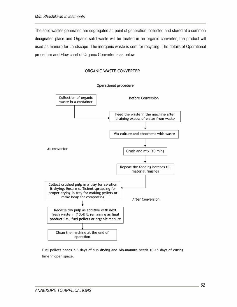
M/s. Shashikiran Investments
ANNEXURE TO APPLICATIONS
62
The solid wastes generated are segregated at point of generation, collected and stored at a common
designated place and Organic solid waste will be treated in an organic converter, the product will
used as manure for Landscape. The inorganic waste is sent for recycling. The details of Operational
procedure and Flow chart of Organic Converter is as below
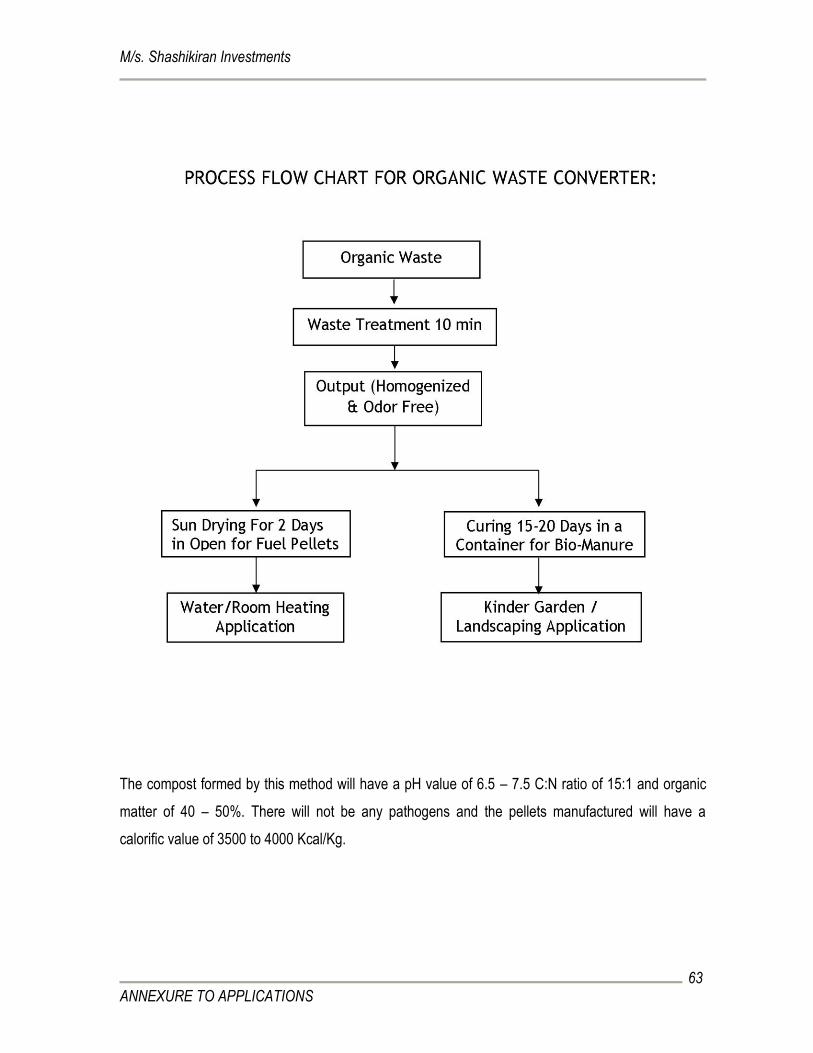
M/s. Shashikiran Investments
ANNEXURE TO APPLICATIONS
63
The compost formed by this method will have a pH value of 6.5 – 7.5 C:N ratio of 15:1 and organic
matter of 40 – 50%. There will not be any pathogens and the pellets manufactured will have a
calorific value of 3500 to 4000 Kcal/Kg.
M/s. Shashikiran Investments
ANNEXURE TO APPLICATIONS
64
ANNEXURE – G
ENVIRONMENTAL MANAGEMENT PLAN
1. INTRODUCTION:
The Environmental Management Plan (EMP) is aimed at mitigating the possible adverse impact of a
project and ensuring the existing environmental quality. The EMP covers all aspects of planning,
construction and operation of the project relevant to environment. It is essential to implement the
EMP right from the planning stage continuing throughout the construction and operation stage.
Therefore the main purpose of Environmental Management Plan (EMP) is to identify the project
specific activities that would have to be considered for the significant adverse impacts and the
mitigation measures required.
The construction phase impacts are short term, restricted to the plot area and not envisaged on the
larger scale. In the operational phase the environmental impacts are due to continuous operation of
the project, hence, the emphasis in the Environment Management Plan (EMP) is to minimize such
impacts. The following mitigation measures are recommended in order to synchronize the economic
development of the project area with the environmental protection of the region.
The emphasis on the EMP development is on the following;
Mitigation measures for each of the activities causing the environmental Impact.
Monitoring plans for checking activities and environmental parameters and monitoring
responsibilities.
Role responsibilities and resource allocation for monitoring; and
Implementation of the Scheduled plan.
Environmental management plan has been discussed in the following sections separately for
Construction phase and Operational phase:
2. EMP DURING CONSTRUCTION PHASE:
During Construction phase, the activities which need to be monitored and managed from the point of
pollution are detailed in the subsequent sections.
M/s. Shashikiran Investments
ANNEXURE TO APPLICATIONS
65
2.1 LEVELLING AND SITE CLEARANCE:
The project is modification and expansion and does not involve additional basement floor / area with
reference to EC obtained proposal, hence additional excavation is not required. The earth excavated
in the project is used for backfilling and formation activities, part of top soil is stored for landscape
development.
Environmental Management during Leveling and Site Clearance
Environmental Impacts Mitigation Proposed Remarks
Noise generation: Caused due to
Excavators and Bulldozers
Most optimum no. of
operation by the heavy
equipment.
Selection of equipment with less
noise generation.
The earth moving equipment are
periodically checked and
maintained for noise levels.
The workers are provided with
adequate PPE such as ear plugs.
To reduce noise level,
equipment provided
with noise control
devices is only used.
Dust generation: Leveling
operations results in the emission
of dust.
The site cleared is periodically
watered to reduce dust emissions.
Barricades like metal sheets are
provided all-round the premises to
avoid fugitive dust emission in to
the neighboring area apart from
water sprinkling.
The workers are provided with
PPE such as nose masks and
goggles to reduce impact.
Tertiary treated water to
be used.
2.2 TRANSPORTATION OF CONSTRUCTION MATERIALS:
During the Transportation of construction materials, minimum no. of vehicles are used. Most
optimum route is being planned to reduce the impact of transportation activity on the environment.
M/s. Shashikiran Investments
ANNEXURE TO APPLICATIONS
66
Environmental Management during Transportation
Environmental Impacts Mitigation Proposed
Noise generation
Quality fuel is being used.
Periodic maintenance of vehicles is required.
Dust generation
Quality packaging of the construction materials.
Construction materials are being covered with tarpaulin sheet to
prevent them from being air borne.
The vehicle speed is being regulated.
The workers carrying transporting materials are being provided
with PPE such as nose masks to reduce impact of air borne
dust on their health.
Vehicular emissions Periodic emission check for vehicles is ensured.
Clean fuel is used for vehicles.
2.3 CONSTRUCTION ACTIVITIES:
During the construction work, the following impacts are identified to monitor and mitigate the level
of impact.
Environmental Management during Construction
Environmental Impacts Mitigation Proposed Remarks
Noise generation
Less noise generating equipment are selected.
Personnel Protective Equipment (PPE) such as
ear plugs and helmets are provided for workers
The working hours are imposed on the
construction workers.
Implementation
responsibility:
Contractor - Civil
Works
Dust generation PPE in the form of nose masks are provided for
construction workers.
Water sprinkling is done to prevent dust from
being air borne.
Barricades like metal sheets are provided all
Implementation
responsibility:
Contractor
M/s. Shashikiran Investments
ANNEXURE TO APPLICATIONS
67
around premises to avoid fugitive dust emission
to neighboring area apart from water sprinkling
Water discharge (construction
works)
Presently, the sewage from construction site / labour
colony is discharged to UGD facilities.
Implementation
responsibility:
Contractor
Air Emissions from
Construction machinery
Periodic check and regular maintenance of
construction machinery for emissions is ensured.
Clean fuel is used in equipments
Implementation
responsibility:
Contractor
2.4 WASTEWATER DISCHARGE:
The sewage generated from the site and labour colony during construction is estimated to be about 7
KLD. Presently, the sewage from construction site is discharged to UGD facilities.
2.4.1 LABOUR CAMPS:
Environmental Management for Labor Camp:
Environmental
Impacts
Mitigation Proposed Remarks
Domestic wastewater
generation
Provision of adequate sanitation facilities is made. Implementation
responsibility:
Contractor
Usage of water Water for labor camps is supplied in required
quantities.
Implementation
responsibility:
Contractor
Solid waste
generation
Segregation of Dry Waste and Wet Waste.
Adequate facilities are provided to handle solid
wastes shall be provided and it will be handed
over to BBMP.
Implementation
responsibility:
Contractor –
maintenance.
2.5 DISPOSAL OF EXCAVATED EARTH:
The project is modification and expansion and does not involve additional basement floor / area with
reference to EC obtained proposal, hence additional excavation is not required. The earth excavated
M/s. Shashikiran Investments
ANNEXURE TO APPLICATIONS
68
in the project is used for backfilling and formation activities, part of top soil is stored for landscape
development.
2.6 PERSONNEL SAFETY SYSTEM:
It is planned to adopt the safe working practices which shall govern all construction works undertaken
throughout the project. Following Safety Aids to all laborers is provided:
Safety Helmets, Safety Belts, Safety Shoes, Hand gloves.
Gumboots while concreting.
Safety Goggles while welding/ Stone dressing etc.,
Facemasks and full body kit while Pest control.
Implementation of Safety procedures such as:
• Using proper lifting techniques.
• Using Safe Scaffolds.
• Hot work permits for Fabrication and Welding.
FINANCIAL ALLOCATION / BUDGETORY PROVISION FOR EMP ASPECTS
(CONSTRUCTION PHASE)
Sl. Description Financial Provision in
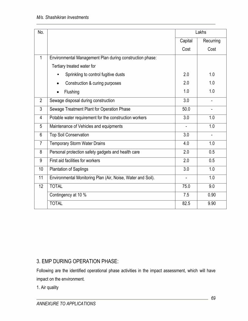
M/s. Shashikiran Investments
ANNEXURE TO APPLICATIONS
69
No. Lakhs
Capital
Cost
Recurring
Cost
1 Environmental Management Plan during construction phase:
Tertiary treated water for
• Sprinkling to control fugitive dusts
Construction & curing purposes
Flushing
2.0
2.0
1.0
1.0
1.0
1.0
2 Sewage disposal during construction 3.0 -
3 Sewage Treatment Plant for Operation Phase 50.0 -
4 Potable water requirement for the construction workers 3.0 1.0
5 Maintenance of Vehicles and equipments - 1.0
6 Top Soil Conservation 3.0 -
7 Temporary Storm Water Drains 4.0 1.0
8 Personal protection safety gadgets and health care 2.0 0.5
9 First aid facilities for workers 2.0 0.5
10 Plantation of Saplings 3.0 1.0
11 Environmental Monitoring Plan (Air, Noise, Water and Soil). - 1.0
12 TOTAL 75.0 9.0
Contingency at 10 % 7.5 0.90
TOTAL 82.5 9.90
3. EMP DURING OPERATION PHASE:
Following are the identified operational phase activities in the impact assessment, which will have
impact on the environment.
1. Air quality
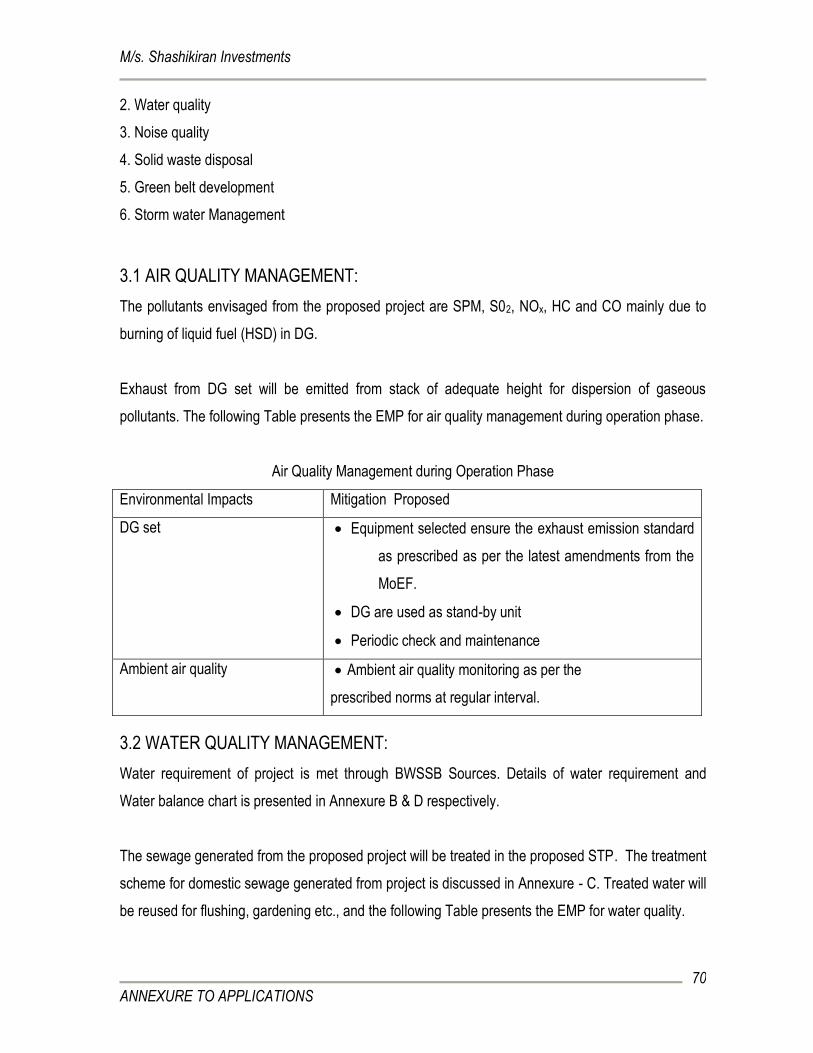
M/s. Shashikiran Investments
ANNEXURE TO APPLICATIONS
70
2. Water quality
3. Noise quality
4. Solid waste disposal
5. Green belt development
6. Storm water Management
3.1 AIR QUALITY MANAGEMENT:
The pollutants envisaged from the proposed project are SPM, S02, NOx, HC and CO mainly due to
burning of liquid fuel (HSD) in DG.
Exhaust from DG set will be emitted from stack of adequate height for dispersion of gaseous
pollutants. The following Table presents the EMP for air quality management during operation phase.
Air Quality Management during Operation Phase
Environmental Impacts Mitigation Proposed
DG set Equipment selected ensure the exhaust emission standard
as prescribed as per the latest amendments from the
MoEF.
DG are used as stand-by unit
Periodic check and maintenance
Ambient air quality Ambient air quality monitoring as per the
prescribed norms at regular interval.
3.2 WATER QUALITY MANAGEMENT:
Water requirement of project is met through BWSSB Sources. Details of water requirement and
Water balance chart is presented in Annexure B & D respectively.
The sewage generated from the proposed project will be treated in the proposed STP. The treatment
scheme for domestic sewage generated from project is discussed in Annexure - C. Treated water will
be reused for flushing, gardening etc., and the following Table presents the EMP for water quality.
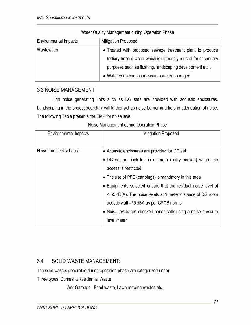
M/s. Shashikiran Investments
ANNEXURE TO APPLICATIONS
71
Water Quality Management during Operation Phase
Environmental impacts Mitigation Proposed
Wastewater Treated with proposed sewage treatment plant to produce
tertiary treated water which is ultimately reused for secondary
purposes such as flushing, landscaping development etc.,
Water conservation measures are encouraged
3.3 NOISE MANAGEMENT
High noise generating units such as DG sets are provided with acoustic enclosures.
Landscaping in the project boundary will further act as noise barrier and help in attenuation of noise.
The following Table presents the EMP for noise level.
Noise Management during Operation Phase
Environmental Impacts Mitigation Proposed
Noise from DG set area Acoustic enclosures are provided for DG set
DG set are installed in an area (utility section) where the
access is restricted
The use of PPE (ear plugs) is mandatory in this area
Equipments selected ensure that the residual noise level of
< 55 dB(A). The noise levels at 1 meter distance of DG room
acoutic wall =75 dBA as per CPCB norms
Noise levels are checked periodically using a noise pressure
level meter
3.4 SOLID WASTE MANAGEMENT:
The solid wastes generated during operation phase are categorized under
Three types: Domestic/Residential Waste
Wet Garbage: Food waste, Lawn mowing wastes etc.,
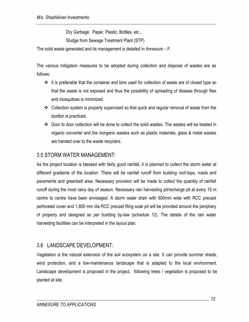
M/s. Shashikiran Investments
ANNEXURE TO APPLICATIONS
72
Dry Garbage: Paper, Plastic, Bottles, etc.,
Sludge from Sewage Treatment Plant (STP)
The solid waste generated and its management is detailed in Annexure – F.
The various mitigation measures to be adopted during collection and disposal of wastes are as
follows:
It is preferable that the container and bins used for collection of waste are of closed type so
that the waste is not exposed and thus the possibility of spreading of disease through flies
and mosquitoes is minimized.
Collection system is properly supervised so that quick and regular removal of waste from the
dustbin is practiced.
Door to door collection will be done to collect the solid wastes. The wastes will be treated in
organic converter and the inorganic wastes such as plastic materials, glass & metal wastes
are handed over to the waste recyclers.
3.5 STORM WATER MANAGEMENT:
As the project location is blessed with fairly good rainfall, it is planned to collect the storm water at
different gradients of the location. There will be rainfall runoff from building roof-tops, roads and
pavements and greenbelt area. Necessary provision will be made to collect the quantity of rainfall
runoff during the most rainy day of season. Necessary rain harvesting pit/recharge pit at every 15 m
centre to centre have been envisaged. A storm water drain with 600mm wide with RCC precast
perforated cover and 1,800 mm dia RCC precast Ring soak pit will be provided around the periphery
of property and designed as per building by-law (schedule 12). The details of the rain water
harvesting facilities can be interpreted in the layout plan.
3.6 LANDSCAPE DEVELOPMENT:
Vegetation is the natural extension of the soil ecosystem on a site. It can provide summer shade,
wind protection, and a low-maintenance landscape that is adapted to the local environment.
Landscape development is proposed in the project, following trees / vegetation is proposed to be
planted at site.

M/s. Shashikiran Investments
ANNEXURE TO APPLICATIONS
73
Trees species proposed in the project:
Sl. No. Scientific name Common name
1 Michelia champaca Champaca
2 Polyalthia fragarans False Ashok, Devdar, Nettilingam
3 Thespesia populnea Indian Tulip tree, Aden Apple
4 Bombax ceiba Cotton tree, Red Cotton tree
5 Pterospermum acerifolium Kanak Champa, Karnikara tree, Bayur Tree, Maple-Leafed Bayur Tree
6 Aegle marmelos Stone apple, Beli fruit, Wood apple
7 Murraya koenigii Curry leaf, Mahanimba, Curry patta, Nimbapatra
8 Azadirachta indica Margosa tree, Neem
9 Sapindus emarginatus Soapnut tree, Kookatakayi, Soapberry
10 Butea monosperma Parrot tree, Palash, Dhak, Tesu , Bastard Teak
11 Pongamia pinnata Honge, Indian Beech tree
12 Bauhinia malabarica Lilac Bauhinia; Malabar Bauhinia
13 Bauhinia purpurea Devakanchan, Purple Butterfly tree, Purple Orchid tree
14 Cassia fistula Golden shower tree, Indian Laburnum
15 Cassia roxburghii Pink Lady, Red Indian Laburnum
16 Saraca asoca Ashoka tree
17 Madhuca indica Butter tree, Hippe
18 Mimusops elengi Sapanish cherry, Bullet-wood tree, Indian Medaller, Bakula
19 Alstonia scholaris Indian devil tree, Pala tree, Dita bark
20 Phyllanthus acidus Star Gooseberry, Malay gooseberry
21 Hibiscus spp Hibiscus
22 Mallotus philippensis Kamala tree, Monkey face tree, Scarlet croton
4. MANAGEMENT OF SOCIO-ECONOMIC ISSUES:
1) Health camp for laborer’s family:
Periodical health camps are organized to monitor and facilitate the occupants of the labor camps.
M/s. Shashikiran Investments
ANNEXURE TO APPLICATIONS
74
HEALTH RISK AND DISASTER MANAGEMENT:
Public health and safety:
Since all the construction related activities are confined to the project site, minimal health related
impacts are envisaged within the project influenced area during the construction stage.
At the project site on an average of 75 persons are engaged, who face direct exposure to dust and
noise generated from the construction activity. This is likely to cause health related affects such as
asthma, bronchitis etc. and hearing impairments.
To minimize these anticipated impacts, following approaches are made
Use of water sprinklers to prevent dust from being air borne.
Providing suitable personal protective equipments (PPE) like mouth mask with filters, noise
mask, helmets etc.
Periodic health check up camp for the laborers are arranged.
Provision of safety belts.
In case of injury Ion site medical treatment and transport are organized.
Safety engineer is employed.
Regular visit of resident medical officer to take care of the first aid and primary medication in
case of emergency.
First aid kit with primary medicines are always available in the medical centre.
Display of action plan and preparedness measures during emergency situations.
5. EMP IMPLEMENTATION SCHEDULE:
Phased according to the priority, the implementation schedule is presented in the following table.
Implementation Schedule for EMP
Sl.
No.
Recommendations Requirement
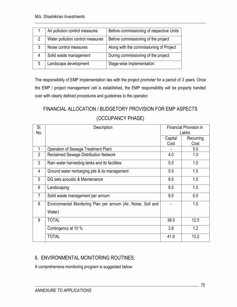
M/s. Shashikiran Investments
ANNEXURE TO APPLICATIONS
75
1 Air pollution control measures Before commissioning of respective Units
2 Water pollution control measures Before commissioning of the project
3 Noise control measures Along with the commissioning of Project
4 Solid waste management During commissioning of the project
5 Landscape development Stage-wise implementation
The responsibility of EMP implementation lies with the project promoter for a period of 3 years. Once
the EMP / project management cell is established, the EMP responsibility will be properly handed
over with clearly defined procedures and guidelines to the operator.
FINANCIAL ALLOCATION / BUDGETORY PROVISION FOR EMP ASPECTS
(OCCUPANCY PHASE)
Sl. No.
Description Financial Provision in Lakhs
Capital Cost
Recurring Cost
1 Operation of Sewage Treatment Plant - 5.0
2 Reclaimed Sewage Distribution Network 4.0 1.0
3 Rain water harvesting tanks and its facilities 5.0 1.0
4 Ground water recharging pits & its management 5.0 1.0
5 DG sets acoustic & Maintenance 8.0 1.0
6 Landscaping 8.0 1.0
7 Solid waste management per annum 8.0 0.5
8 Environmental Monitoring Plan per annum (Air, Noise, Soil and
Water)
- 1.5
9 TOTAL 38.0 12.0
Contingency at 10 % 3.8 1.2
TOTAL 41.8 13.2
6. ENVIRONMENTAL MONITORING ROUTINES:
A comprehensive monitoring program is suggested below:
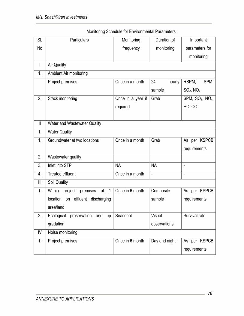
M/s. Shashikiran Investments
ANNEXURE TO APPLICATIONS
76
Monitoring Schedule for Environmental Parameters
Sl.
No
Particulars
Monitoring
frequency
Duration of
monitoring
Important
parameters for
monitoring
I Air Quality
1. Ambient Air monitoring
Project premises Once in a month 24 hourly
sample
RSPM, SPM,
SO2, NOx
2. Stack monitoring
Once in a year if
required
Grab SPM, SO2, NOx,
HC, CO
II Water and Wastewater Quality
1. Water Quality
1. Groundwater at two locations Once in a month Grab As per KSPCB
requirements
2. Wastewater quality
3. Inlet into STP NA NA -
4. Treated effluent Once in a month - -
III Soil Quality
1. Within project premises at 1
location on effluent discharging
area/land
Once in 6 month Composite
sample
As per KSPCB
requirements
2. Ecological preservation and up
gradation
Seasonal Visual
observations
Survival rate
IV Noise monitoring
1. Project premises Once in 6 month Day and night As per KSPCB
requirements
M/s. Shashikiran Investments
ANNEXURE TO APPLICATIONS
77
ANNEXURE – H
RAIN WATER MANAGEMENT SCHEME
RAIN WATER HARVESTING AND GROUNDWATER RECHARGING:
VOLUME OF RAIN WATER HARVESTED:
The total amount/quantity of water i.e., received in the form of rainfall over an area is called the rain
water endowment of that area, out of which the amount of water that can be effectively harvested is
called the rain water harvesting potential.
Rain Water harvesting potential = Intensity of Rainfall (m) x Roof Area x
Impermeability Factor
The collection efficiency accounts for the fact that all the rain water falling over an area cannot be
effectively harvested due to losses on account of evaporation, spillage or run off etc.,
According to the data available from the Indian Meteorological Department, the Average annual
rainfall around month of September = 194.80mm
Assuming that about 90% Rainfall can be effectively harvested.
Number of Rainy Days = 9.3
Therefore the I.R = 194.80/9.3= 20.94 mm/day or 0.02094 m/day
or 0.021 m/day
Quantity of roof top rain water harvested from the project:
The top floor area of the project (Apartment and Commercial block) is about 3,046 sq m.
For rain water harvesting consider 75 % of this total area = 2,284.5 sq m.
Total Quantity of Rain Water that can be harvested from the building is as follows.
Rain water (Q) from Roof top = 0.021 x 2284.5 x 0.9
= 43.17 cum/day or say 44 cum/day
Rain water storage sump of 60 cum capacity is proposed to collect the rain water and will be reused
for domestic purposes.
RAIN WATER FROM PAVED & UNPAVED AREAS:
The amount of storm water that the landscaped area will produce can be determined by considering
the impermeability factor to be 0.3.

M/s. Shashikiran Investments
ANNEXURE TO APPLICATIONS
78
Q = 0.021 x 2,157.60sq m x 0.3
= 15.86 cum/day or say 16 cum/day
The amount of storm water that the paved area will produce can be determined by considering the
impermeability factor to be 0.9.
Q = 0.021 x 2,246.19 sq m x 0.9
= 42.45 cum/day or say 43 cum/day
The Total amount of storm water = landscaped area + paved area
= 16 + 43 cum/day
= 59 cum/day
Ground water recharging pits along the inner periphery of the boundary wall with recharging pit of
size 1.2 m dia x 7.0 m deep spaced with 10 nos recharge pits. Recharge pits are filled with graded
media comprising of Boulder at the bottom and with coarse aggregates to facilitate percolation of
harvested rain water to Recharge Ground Water table. The Pits are interconnected in such a way
that the rain led to the first recharge pit is also led to the next pit. The excess rain water shall be
drained off to the storm water drain.
M/s. Shashikiran Investments
ANNEXURE TO APPLICATIONS
79
ANNEXURE: I
DISASTER MANAGEMENT PLANS FOR PRE CONSTRUCTION PHASE:
Risk and disaster management plan:
Disaster is an unexpected event due to sudden failure of the system, external threats, internal
disturbances, earth quakes, fire and accidents. Thus an appropriate management plan shall be
incorporated.
Precautions:
Once the likelihood of the disaster is suspected, preventive actions should be undertaken by
the project in-charge.
Conditional maintenance of equipments, materials, and expertise for use during emergency.
The electrical systems shall be provided with automatic circuit breakers activated by over
current.
Proper escape routes are planned and displayed in the public domain.
Selected representatives are given proper training to guide other inhabitants during Fire
accidents.
Periodic awareness program is conducted for the workers on their roles during emergency
situations.
Important telephone numbers like police authorities, fire department and hospitals etc., of use during
emergency situations will be made available.
M/s. Shashikiran Investments
ANNEXURE TO APPLICATIONS
80
ANNEXURE: J
Environmental Management Plan for control of Dust and Noise pollution during
construction phase:
Environmental Impacts Mitigation Proposed
1. Leveling and Site Clearance:
Noise generation: Caused
due to Excavators and
Bulldozers
Most optimum no. of operation by the heavy equipment
Selection of equipment with less noise generation are used
The earth moving equipment are periodically checked and
maintained for noise levels.
The workers are provided with adequate PPE such as ear
plugs to reduce impact of high noise levels.
Dust generation: Leveling
operations results in the
emission of dust.
The site cleared is periodically watered to reduce emission of
dust particles
Barricades like metal sheets are provided all round the
premises to avoid fugitive dust emission in to the neighboring
area apart from water sprinkling.
The workers are provided with PPE such as nose masks and
goggles to reduce impact on health.
2. Transportation of Construction Materials:
Dust generation
Quality packaging of the construction materials
Construction materials are covered with tarpaulin sheet to
prevent them from being air borne
The vehicle speed is regulated
The workers transporting materials are provided with PPE
such as nose masks to reduce impact of air borne dust on
their health.
1. Construction Activities:
Noise generation
Quality fuel is used.
Periodic maintenance of vehicles is required
M/s. Shashikiran Investments
ANNEXURE TO APPLICATIONS
81
Noise generation
Selection of Less noise generating equipment
Personnel Protective Equipment (PPE) such as ear plugs and
helmets are provided for workers
The working hours is imposed on the construction workers.
Dust generation PPE in the form of nose masks are provided for construction
workers
Use of water sprays to prevent dust from being air borne
Barricades like metal sheets are provided all around the
premises to avoid fugitive dust emission in to the neighboring
area apart from water sprinkling
M/s. Shashikiran Investments
ANNEXURE TO APPLICATIONS
82
ANNEXURE: K
RISK ASSESSMENT & MANAGEMENT PLAN:
a. Construction Phase:
Sl. No. Potential Mitigation
1 Accidental fire Fire safety gadgets.
2 Fall of objects Use of personal protection devices like helmets.
3 Working at great heights Protection to prevent fall with life safety belts and nets.
4 Accidents from construction
machinery
Personal protection gadgets
5 Electrical mishap Adopting safety measures to prevent any act of
negligence and providing electrical safety measures like
fire extinguishers.
b. All necessary measures will be taken to avoid accidents and mishaps during operation phase.
Precautions for Risk and Disaster Management Plan:
Once the likelihood of the disaster is suspected, preventive actions will be undertaken by the
project in-charge.
Conditional maintenance of equipments, materials, and expertise for use during emergency.
The electrical systems are provided with automatic circuit breakers activated by over current.
Fire extinguishers are provided at pre-notified locations inside the building.
Proper escape routes are planned and displayed in the public domain.
Selected representatives are given proper training to guide other inhabitants during Fire
accidents.
Periodic awareness program is conducted for the occupants on their roles during emergency
situations.
Important telephone numbers like police authorities, fire department and hospitals etc. of use
during emergency situations are made available.

M/s. Shashikiran Investments
ANNEXURE TO APPLICATIONS
83
ANNEXURE: L
SOIL INVESTIGATION REPORT

M/s. Shashikiran Investments
ANNEXURE TO APPLICATIONS
84
ANNEXURE – M
TRAFFIC SURVEY AND MANAGEMENT PLAN
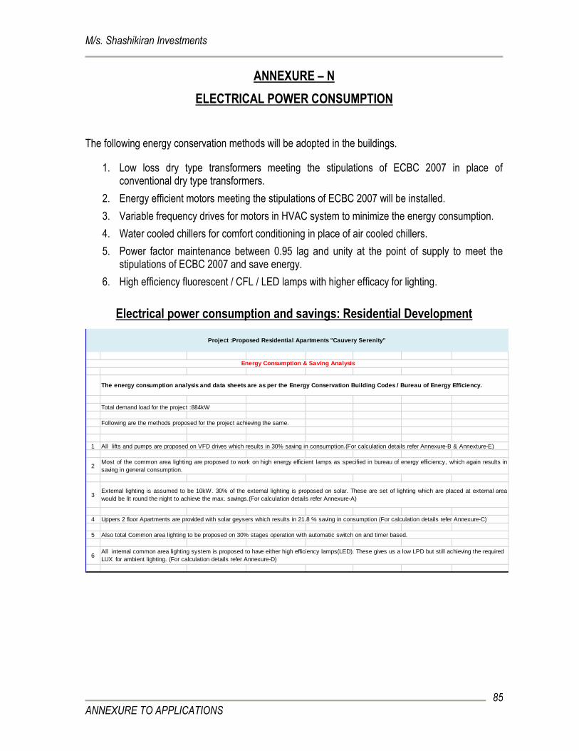
M/s. Shashikiran Investments
ANNEXURE TO APPLICATIONS
85
ANNEXURE – N
ELECTRICAL POWER CONSUMPTION
The following energy conservation methods will be adopted in the buildings.
1. Low loss dry type transformers meeting the stipulations of ECBC 2007 in place of conventional dry type transformers.
2. Energy efficient motors meeting the stipulations of ECBC 2007 will be installed.
3. Variable frequency drives for motors in HVAC system to minimize the energy consumption.
4. Water cooled chillers for comfort conditioning in place of air cooled chillers.
5. Power factor maintenance between 0.95 lag and unity at the point of supply to meet the stipulations of ECBC 2007 and save energy.
6. High efficiency fluorescent / CFL / LED lamps with higher efficacy for lighting.
Electrical power consumption and savings: Residential Development
Total demand load for the project :884kW
Following are the methods proposed for the project achieving the same.
1 All lifts and pumps are proposed on VFD drives which results in 30% saving in consumption.(For calculation details refer Annexure-B & Annexture-E)
2
3
4
5
6
Project :Proposed Residential Apartments "Cauvery Serenity"
Energy Consumption & Saving Analysis
The energy consumption analysis and data sheets are as per the Energy Conservation Building Codes / Bureau of Energy Efficiency.
All internal common area lighting system is proposed to have either high efficiency lamps(LED). These gives us a low LPD but still achieving the required
LUX for ambient lighting. (For calculation details refer Annexure-D)
Most of the common area lighting are proposed to work on high energy efficient lamps as specified in bureau of energy efficiency, which again results in
saving in general consumption.
External lighting is assumed to be 10kW. 30% of the external lighting is proposed on solar. These are set of lighting which are placed at external area
would be lit round the night to achieve the max. savings.(For calculation details refer Annexure-A)
Also total Common area lighting to be proposed on 30% stages operation with automatic switch on and timer based.
Uppers 2 floor Apartments are provided with solar geysers which results in 21.8 % saving in consumption (For calculation details refer Annexure-C)
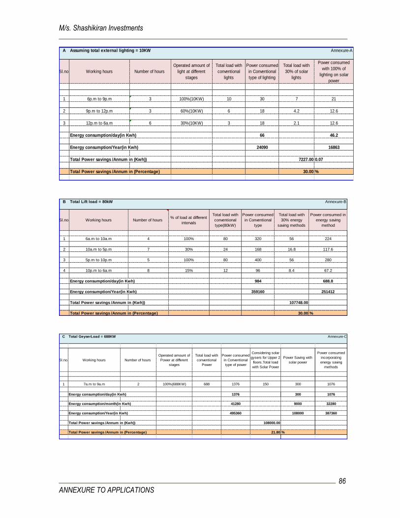
M/s. Shashikiran Investments
ANNEXURE TO APPLICATIONS
86
A Assuming total external lighting = 10KW Annexure-A
Sl.no. Working hours Number of hours
Operated amount of
light at different
stages
Total load with
conventional
lights
Power consumed
in Conventional
type of lighting
Total load with
30% of solar
lights
Power consumed
with 100% of
lighting on solar
power
1 6p.m to 9p.m 3 100%(10KW) 10 30 7 21
2 9p.m to 12p.m 3 60%(10KW) 6 18 4.2 12.6
3 12p.m to 6a.m 6 30%(10KW) 3 18 2.1 12.6
Energy consumption/day(in Kwh) 66 46.2
Energy consumption/Year(in Kwh) 24090 16863
Total Power savings /Annum in (Kwh)) 7227.00 0.07
Total Power savings /Annum in (Percentage) 30.00 %
B Total Lift load = 80kW Annexure-B
Sl.no. Working hours Number of hours % of load at different
intervals
Total load with
conventional
type(80kW)
Power consumed
in Conventional
type
Total load with
30% energy
saving methods
Power consumed in
energy saving
method
1 6a.m to 10a.m 4 100% 80 320 56 224
2 10a.m to 5p.m 7 30% 24 168 16.8 117.6
3 5p.m to 10p.m 5 100% 80 400 56 280
4 10p.m to 6a.m 8 15% 12 96 8.4 67.2
Energy consumption/day(in Kwh) 984 688.8
Energy consumption/Year(in Kwh) 359160 251412
Total Power savings /Annum in (Kwh)) 107748.00
Total Power savings /Annum in (Percentage) 30.00 %
C Total GeyserLoad = 688KW Annexure-C
Sl.no. Working hours Number of hours
Operated amount of
Power at different
stages
Total load with
conventional
Power
Power consumed
in Conventional
type of power
Considering solar
gysers for Upper 2
floors.Total load
with Solar Power
Power Saving with
solar power
Power consumed
incorporating
energy saving
methods
1 7a.m to 9a.m 2 100%(688KW) 688 1376 150 300 1076
Energy consumption/day(in Kwh) 1376 300 1076
Energy consumption/month(in Kwh) 41280 9000 32280
Energy consumption/Year(in Kwh) 495360 108000 387360
Total Power savings /Annum in (Kwh)) 108000.00
Total Power savings /Annum in (Percentage) 21.80 %
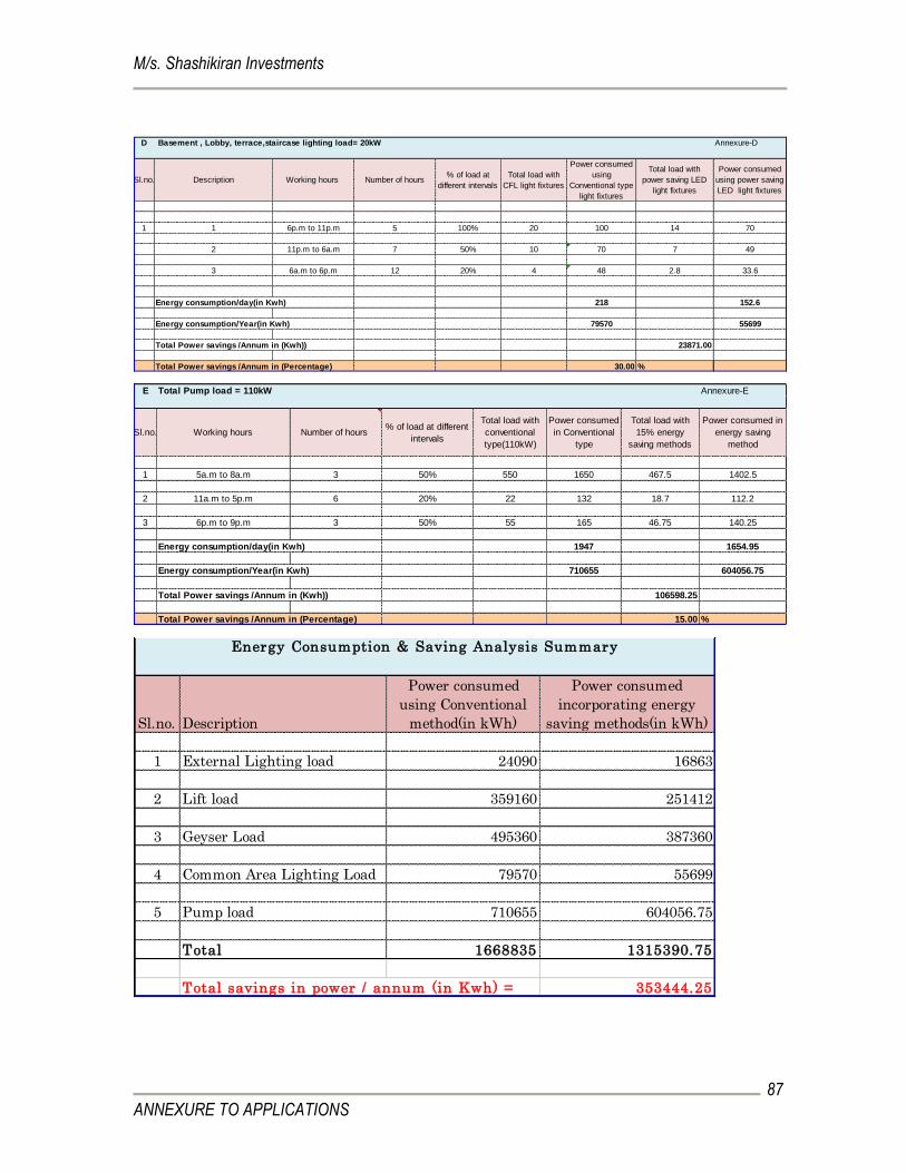
M/s. Shashikiran Investments
ANNEXURE TO APPLICATIONS
87
D Basement , Lobby, terrace,staircase lighting load= 20kW Annexure-D
Sl.no. Description Working hours Number of hours% of load at
different intervals
Total load with
CFL light fixtures
Power consumed
using
Conventional type
light fixtures
Total load with
power saving LED
light fixtures
Power consumed
using power saving
LED light fixtures
1 1 6p.m to 11p.m 5 100% 20 100 14 70
2 11p.m to 6a.m 7 50% 10 70 7 49
3 6a.m to 6p.m 12 20% 4 48 2.8 33.6
Energy consumption/day(in Kwh) 218 152.6
Energy consumption/Year(in Kwh) 79570 55699
Total Power savings /Annum in (Kwh)) 23871.00
Total Power savings /Annum in (Percentage) 30.00 % E Total Pump load = 110kW Annexure-E
Sl.no. Working hours Number of hours % of load at different
intervals
Total load with
conventional
type(110kW)
Power consumed
in Conventional
type
Total load with
15% energy
saving methods
Power consumed in
energy saving
method
1 5a.m to 8a.m 3 50% 550 1650 467.5 1402.5
2 11a.m to 5p.m 6 20% 22 132 18.7 112.2
3 6p.m to 9p.m 3 50% 55 165 46.75 140.25
Energy consumption/day(in Kwh) 1947 1654.95
Energy consumption/Year(in Kwh) 710655 604056.75
Total Power savings /Annum in (Kwh)) 106598.25
Total Power savings /Annum in (Percentage) 15.00 %
Sl.no. Description
Power consumed
using Conventional
method(in kWh)
Power consumed
incorporating energy
saving methods(in kWh)
1 External Lighting load 24090 16863
2 Lift load 359160 251412
3 Geyser Load 495360 387360
4 Common Area Lighting Load 79570 55699
5 Pump load 710655 604056.75
Total 1668835 1315390.75
Total savings in power / annum (in Kwh) = 353444.25
Energy Consumption & Saving Analysis Summary
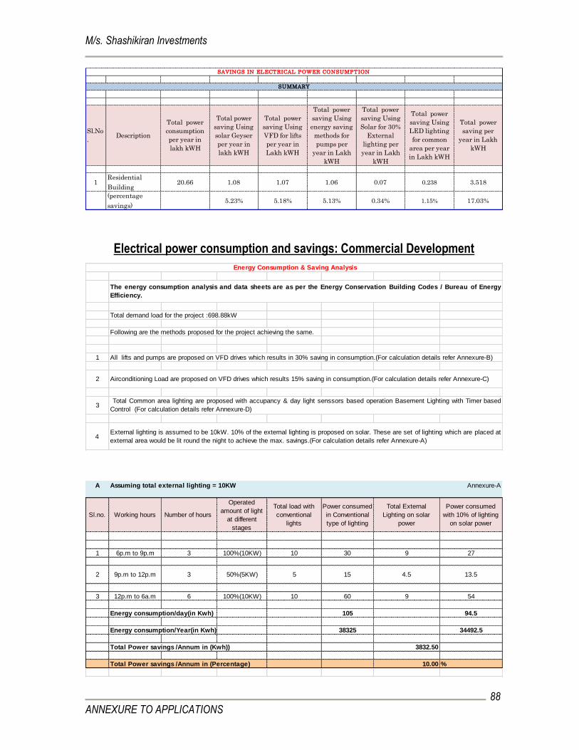
M/s. Shashikiran Investments
ANNEXURE TO APPLICATIONS
88
Sl.No
.Description
Total power
consumption
per year in
lakh kWH
Total power
saving Using
solar Geyser
per year in
lakh kWH
Total power
saving Using
VFD for lifts
per year in
Lakh kWH
Total power
saving Using
energy saving
methods for
pumps per
year in Lakh
kWH
Total power
saving Using
Solar for 30%
External
lighting per
year in Lakh
kWH
Total power
saving Using
LED lighting
for common
area per year
in Lakh kWH
Total power
saving per
year in Lakh
kWH
1Residential
Building20.66 1.08 1.07 1.06 0.07 0.238 3.518
(percentage
savings)5.23% 5.18% 5.13% 0.34% 1.15% 17.03%
SAVINGS IN ELECTRICAL POWER CONSUMPTION
SUMMARY
Electrical power consumption and savings: Commercial Development
Total demand load for the project :698.88kW
Following are the methods proposed for the project achieving the same.
1 All lifts and pumps are proposed on VFD drives which results in 30% saving in consumption.(For calculation details refer Annexure-B)
2
3
4
Energy Consumption & Saving Analysis
The energy consumption analysis and data sheets are as per the Energy Conservation Building Codes / Bureau of Energy
Efficiency.
Airconditioning Load are proposed on VFD drives which results 15% saving in consumption.(For calculation details refer Annexure-C)
External lighting is assumed to be 10kW. 10% of the external lighting is proposed on solar. These are set of lighting which are placed at
external area would be lit round the night to achieve the max. savings.(For calculation details refer Annexure-A)
Total Common area lighting are proposed with accupancy & day light senssors based operation Basement Lighting with Timer based
Control (For calculation details refer Annexure-D)
A Assuming total external lighting = 10KW Annexure-A
Sl.no. Working hours Number of hours
Operated
amount of light
at different
stages
Total load with
conventional
lights
Power consumed
in Conventional
type of lighting
Total External
Lighting on solar
power
Power consumed
with 10% of lighting
on solar power
1 6p.m to 9p.m 3 100%(10KW) 10 30 9 27
2 9p.m to 12p.m 3 50%(5KW) 5 15 4.5 13.5
3 12p.m to 6a.m 6 100%(10KW) 10 60 9 54
Energy consumption/day(in Kwh) 105 94.5
Energy consumption/Year(in Kwh) 38325 34492.5
Total Power savings /Annum in (Kwh)) 3832.50
Total Power savings /Annum in (Percentage) 10.00 %
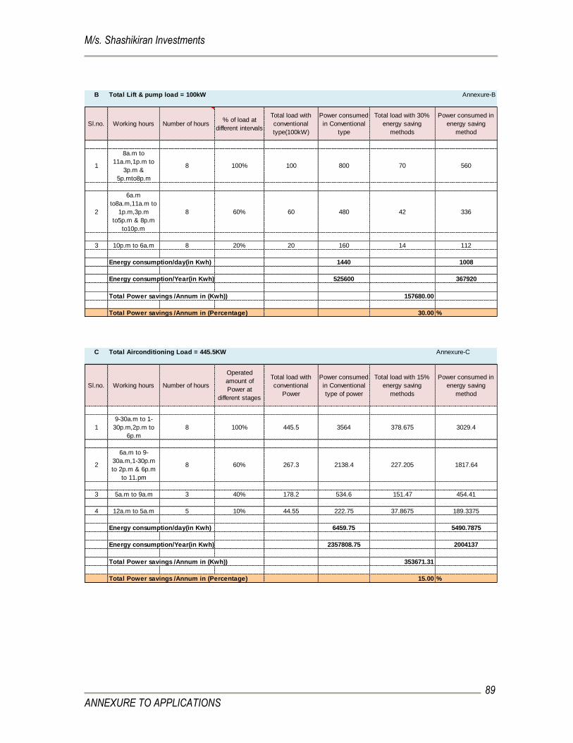
M/s. Shashikiran Investments
ANNEXURE TO APPLICATIONS
89
B Total Lift & pump load = 100kW Annexure-B
Sl.no. Working hours Number of hours % of load at
different intervals
Total load with
conventional
type(100kW)
Power consumed
in Conventional
type
Total load with 30%
energy saving
methods
Power consumed in
energy saving
method
1
8a.m to
11a.m,1p.m to
3p.m &
5p.mto8p.m
8 100% 100 800 70 560
2
6a.m
to8a.m,11a.m to
1p.m,3p.m
to5p.m & 8p.m
to10p.m
8 60% 60 480 42 336
3 10p.m to 6a.m 8 20% 20 160 14 112
Energy consumption/day(in Kwh) 1440 1008
Energy consumption/Year(in Kwh) 525600 367920
Total Power savings /Annum in (Kwh)) 157680.00
Total Power savings /Annum in (Percentage) 30.00 %
C Total Airconditioning Load = 445.5KW Annexure-C
Sl.no. Working hours Number of hours
Operated
amount of
Power at
different stages
Total load with
conventional
Power
Power consumed
in Conventional
type of power
Total load with 15%
energy saving
methods
Power consumed in
energy saving
method
1
9-30a.m to 1-
30p.m,2p.m to
6p.m
8 100% 445.5 3564 378.675 3029.4
2
6a.m to 9-
30a.m,1-30p.m
to 2p.m & 6p.m
to 11.pm
8 60% 267.3 2138.4 227.205 1817.64
3 5a.m to 9a.m 3 40% 178.2 534.6 151.47 454.41
4 12a.m to 5a.m 5 10% 44.55 222.75 37.8675 189.3375
Energy consumption/day(in Kwh) 6459.75 5490.7875
Energy consumption/Year(in Kwh) 2357808.75 2004137
Total Power savings /Annum in (Kwh)) 353671.31
Total Power savings /Annum in (Percentage) 15.00 %
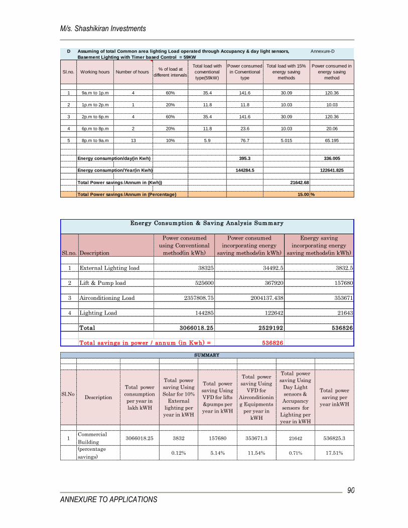
M/s. Shashikiran Investments
ANNEXURE TO APPLICATIONS
90
D Annexure-D
Sl.no. Working hours Number of hours % of load at
different intervals
Total load with
conventional
type(59kW)
Power consumed
in Conventional
type
Total load with 15%
energy saving
methods
Power consumed in
energy saving
method
1 9a.m to 1p.m 4 60% 35.4 141.6 30.09 120.36
2 1p.m to 2p.m 1 20% 11.8 11.8 10.03 10.03
3 2p.m to 6p.m 4 60% 35.4 141.6 30.09 120.36
4 6p.m to 8p.m 2 20% 11.8 23.6 10.03 20.06
5 8p.m to 9a.m 13 10% 5.9 76.7 5.015 65.195
Energy consumption/day(in Kwh) 395.3 336.005
Energy consumption/Year(in Kwh) 144284.5 122641.825
Total Power savings /Annum in (Kwh)) 21642.68
Total Power savings /Annum in (Percentage) 15.00 %
Assuming of total Common area lighting Load operated through Accupancy & day light sensors,
Basement Lighting with Timer based Control = 59KW
Sl.no. Description
Power consumed
using Conventional
method(in kWh)
Power consumed
incorporating energy
saving methods(in kWh)
Energy saving
incorporating energy
saving methods(in kWh)
1 External Lighting load 38325 34492.5 3832.5
2 Lift & Pump load 525600 367920 157680
3 Airconditioning Load 2357808.75 2004137.438 353671
4 Lighting Load 144285 122642 21643
Total 3066018.25 2529192 536826
Total savings in power / annum (in Kwh) = 536826
Energy Consumption & Saving Analysis Summary
Sl.No
.Description
Total power
consumption
per year in
lakh kWH
Total power
saving Using
Solar for 10%
External
lighting per
year in kWH
Total power
saving Using
VFD for lifts
&pumps per
year in kWH
Total power
saving Using
VFD for
Airconditionin
g Equipments
per year in
kWH
Total power
saving Using
Day Light
sensors &
Accupancy
sensors for
Lighting per
year in kWH
Total power
saving per
year inkWH
1Commercial
Building3066018.25 3832 157680 353671.3 21642 536825.3
(percentage
savings)0.12% 5.14% 11.54% 0.71% 17.51%
SUMMARY

M/s. Shashikiran Investments
ANNEXURE TO APPLICATIONS
91
ANNEXURE – O
Project related drawings / plans