Embed Size (px)
Citation preview

7/28/2019 project report on Islanding System
http://slidepdf.com/reader/full/project-report-on-islanding-system 1/63
AUTOMATIC ISLANDING SYSTEM
A PROJECT REPORT ON
AUTOMATIC ISLANDINGSYSTEM
(MICROCONTROLLER 89S51-BASED)
SUBMITTED BY
ANANT.K.MOMAYA FEEG10124
VISMAY.H.NAGDA FEEG10125
NIKHIL .V. PANCHAL FEEG10129
ANUKUL. A .RAMJIYANI FEEG10141
KHUSHAL.M .SAPARIYA FEEG10146
UNDER THE GUIDANCE OF
PROF.S.N.KOLTE
DEPARTMENT OF ELECTRICAL ENGINEERING
K.J.SOMAIYA.POLYTECHNICVIDYAVIHAR
MUMBAI-77
2012-2013

7/28/2019 project report on Islanding System
http://slidepdf.com/reader/full/project-report-on-islanding-system 2/63
AUTOMATIC ISLANDING SYSTEM
K.J.SOMAIYA.POLYTHECHNIC
VIDYANAGAR, VIDYAVIHAR
MUMBAI-77
CERTIFICATETHIS IS TO MENTION THAT STUDENT MENTIONED BELOW 5TH SEM
ELECTRICAL ENGINEERING HAVE SATISFACTORILY COMPLETED
THEIR TERM IN PROJECT WORKSHOP NAMED
ISLANDING SYSTEM
(MICROCONTROLLER 89S51 BASED)DURING ACADEMIC YEAR 2012-2013
SUBMITTED BY
ANANT .K.MOMAYA FEEG10124
PROJECT GUIDE H.O.D OF ELECT DEPT
PROF.S.N.KOLTE PROF.B.S.MOTLING
PRINCIPAL
ELECT EXAMINAR MRS.B.PADMAJA

7/28/2019 project report on Islanding System
http://slidepdf.com/reader/full/project-report-on-islanding-system 3/63
AUTOMATIC ISLANDING SYSTEM
PREFACE
We take an opportunity to present this project report on
“ISLANDING SYSTEM” and put before readers some useful
information regarding our project.
We have made sincere attempt and taken every care to present this
matter in precise form, the language being as simple as possible.
We are sure that the information contained in this volume would
certainly prove useful for better insight in the scope and dimension of
this project in its true perspective.
The task of completion of this project though being difficult was made
quite simple , interesting and successful due to deep involvement and
complete dedication of our group members and our
Guide, Prof. S.N.KOLTE.

7/28/2019 project report on Islanding System
http://slidepdf.com/reader/full/project-report-on-islanding-system 4/63

7/28/2019 project report on Islanding System
http://slidepdf.com/reader/full/project-report-on-islanding-system 5/63
AUTOMATIC ISLANDING SYSTEM

7/28/2019 project report on Islanding System
http://slidepdf.com/reader/full/project-report-on-islanding-system 6/63
AUTOMATIC ISLANDING SYSTEM
Introduction
When Grid collapses, many questions remain as to what happened to cause the Blackout
and whether it could have been prevented, or at least contained to a smaller area. It willtake some time to sort through the data and figure out answers. In the mean time, we are
all asking – can it happen again? Can it happen here? Unfortunately, the short answer is
yes. No power system is designed to handle simultaneous outages of multiple
transmission lines and generators. We have heard arguments that “it won’t happen here
because we have built in safeguards to prevent this from happening.” However, every
system in the India has these same safeguards, just to a different extent. Unfortunately,
they just did not work as expected on many occasions.
There have been statements made that we have a “Third World” transmission system, that
deregulation of the electric industry is the culprit, or that the opposite is true – the lack of
deregulation is to blame, and that we need extensive investment in the transmission
system. While all of these statements contain a grain of truth, none of them are strictly
accurate. The remainder of this article highlights these grains of truth and more
accurately depicts what steps can be taken to reduce the risks of a widespread blackout.
Although we will need to wait for the Department of Energy’s report on what happened
to get the full picture, there are some immediate and relatively low cost steps that can be
taken now to reduce the chances of another major blackout affecting you and your
customers. Below are the actions utilities can take now:
Evaluate and test your safeguard schemes
It is important to understand that at every moment in time, supply and demand on the
power system must be balanced, or blackouts can occur. If there is a significant
imbalance in portions of the system, both the frequency and the voltage are impacted. If
there is more consumption than supply in an area, then, the frequency and voltage drop. If
there is more supply than demand in an area, then frequency climbs. Different parts of the
system can experience these same events simultaneously and can “swing” against each

7/28/2019 project report on Islanding System
http://slidepdf.com/reader/full/project-report-on-islanding-system 7/63
AUTOMATIC ISLANDING SYSTEM
other, with the transmission system acting as sort of a spring, and can cause a cascading
blackout.
Safeguards have been put in place to help prevent this cascading. These safeguards
typically include:
• Under-frequency Load Shedding – This is a scheme designed to open distribution
circuits when the frequency is too low to reduce demand and help restore the balance
between supply and demand.
• Generator Over-speed Protection – This is a scheme designed to both protect the
generators from spinning too fast and causing permanent damage to the turbines, and to
reduce supply to help restore the balance between supply and demand when the
frequency is too high.
The above two schemes are universally applied. The two schemes below are applied on a
discretionary basis:
• Out-of-Step Tripping and Islanding Schemes – These are schemes that
are designed to separate systems from each other when one system is out of control.
•
Under-voltage Load Shedding – It appears that Cleveland went black mostlydue to a phenomenon called voltage collapse. If demand had been reduced in Cleveland
as a result of low voltage, it may have prevented a total outage of Cleveland and the
ensuing cascading Blackout.
These automatic safeguard schemes were often designed and installed years ago and can
be out of date. Some actions to consider:
• Consider implementing out-of-step tripping and islanding schemes, and under
voltage load shedding schemes, if not already applied
• Perform transient, dynamic and voltage stability studies to optimize these
safeguard schemes, and evaluate how well they coordinate with each other
• Update relays to microprocessor controlled relays
• Test the relays and systems periodically

7/28/2019 project report on Islanding System
http://slidepdf.com/reader/full/project-report-on-islanding-system 8/63
AUTOMATIC ISLANDING SYSTEM

7/28/2019 project report on Islanding System
http://slidepdf.com/reader/full/project-report-on-islanding-system 9/63
AUTOMATIC ISLANDING SYSTEM
Diodes
Diodes are components that allow current to flow in only one direction. They have a positive side (leg) and a negative side. When the voltage on the positive leg is higher than
on the negative leg then current flows through the diode (the resistance is very low).
When the voltage is lower on the positive leg than on the negative leg then the current
does not flow (the resistance is very high). The negative leg of a diode is the one with the
line closest to it. It is called the cathode. The postive end is called the anode.
LED
The LED
Light Emitting Diodes are great for projects because they provide visual entertainment.
LEDs use a special material which emits light when current flows through it. Unlike light
bulbs, LEDs never burn out unless their current limit is passed. A current of 0.02 Amps(20 mA) to 0.04 Amps (40 mA) is a good range for LEDs. They have a positive leg and a
negative leg just like regular diodes. To find the positive side of an LED, look for a line
in the metal inside the LED. It may be difficult to see the line. This line is closest to the
positive side of the LED. Another way of finding the positive side is to find a flat spot on
the edge of the LED. This flat spot is on the negative side.
When current is flowing through an LED the voltage on the positive leg is about 1.4 volts
higher than the voltage on the negative side. Remember that there is no resistance to limit
the current so a resistor must be used in series with the LED to avoid destroying it.
Resistors
Resistors are components that have a predetermined resistance. Resistance determines
how much current will flow through a component. Resistors are used to control voltages
7/28/2019 project report on Islanding System
http://slidepdf.com/reader/full/project-report-on-islanding-system 10/63
AUTOMATIC ISLANDING SYSTEM
and currents. A very high resistance allows very little current to flow. Air has very high
resistance. Current almost never flows through air. (Sparks and lightning are brief
displays of current flow through air. The light is created as the current burns parts of the
air.) A low resistance allows a large amount of current to flow. Metals have very low
resistance. That is why wires are made of metal. They allow current to flow from one
point to another point without any resistance. Wires are usually covered with rubber or
plastic. This keeps the wires from coming in contact with other wires and creating short
circuits. High voltage power lines are covered with thick layers of plastic to make them
safe, but they become very dangerous when the line breaks and the wire is exposed and is
no longer separated from other things by insulation.
Resistance is given in units of ohms. (Ohms are named after Mho Ohms who played with
electricity as a young boy in Germany.) Common resistor values are from 100 ohms to
100,000 ohms. Each resistor is marked with colored stripes to indicate it’s resistance. To
learn how to calculate the value of a resistor by looking at the stripes on the resistor, go to
Resistor Values which includes more information about resistors.
Variable Resistors
Variable resistors are also common components. They have a dial or a knob that allows
you to change the resistance. This is very useful for many situations. Volume controls are
variable resistors. When you change the volume you are changing the resistance which
changes the current. Making the resistance higher will let less current flow so the volume
goes down. Making the resistance lower will let more current flow so the volume goes
up. The value of a variable resistor is given as it’s highest resistance value. For example,
a 500 ohm variable resistor can have a resistance of anywhere between 0 ohms and 500
ohms. A variable resistor may also be called a potentiometer (pot for short).
Switches
Switches are devices that create a short circuit or an open circuit depending on the
position of the switch. For a light switch, ON means short circuit (current flows through
the switch, lights light up and people dance.) When the switch is OFF, that means there is

7/28/2019 project report on Islanding System
http://slidepdf.com/reader/full/project-report-on-islanding-system 11/63
AUTOMATIC ISLANDING SYSTEM
an open circuit (no current flows, lights go out and people settle down. This effect on
people is used by some teachers to gain control of loud classes.)
When the switch is ON it looks and acts like a wire. When the switch is OFF there is no
connection.
This is a small switch inside the controller connected to the full on power and full off
brake. Gives positive contact, and eliminates the resistor from the circuit. A very efficient
way of handling power, even in the newer electronic controllers.
A micro switch is a generic term used to refer to an electric switch that is designed to be
actuated by the physical motion of mechanical devices and is generally packaged in a
small form factor to allow placement in small spaces. They are very common due to their
low cost and extreme durability, typically greater than 1 million cycles and up to 10
million cycles for heavy duty models. This durability is a natural consequence of the
design.
Transistor
Transistors are basic components in all of today's electronics. They are just simple
switches that we can use to turn things on and off. Even though they are simple, they arethe most important electrical component. For example, transistors are almost the only
components used to build a Pentium processor. A single Pentium chip has about 3.5
million transistors. The ones in the Pentium are smaller than the ones we will use but they
work the same way.
Transistors that we will use in projects look like this:
7/28/2019 project report on Islanding System
http://slidepdf.com/reader/full/project-report-on-islanding-system 12/63
AUTOMATIC ISLANDING SYSTEM
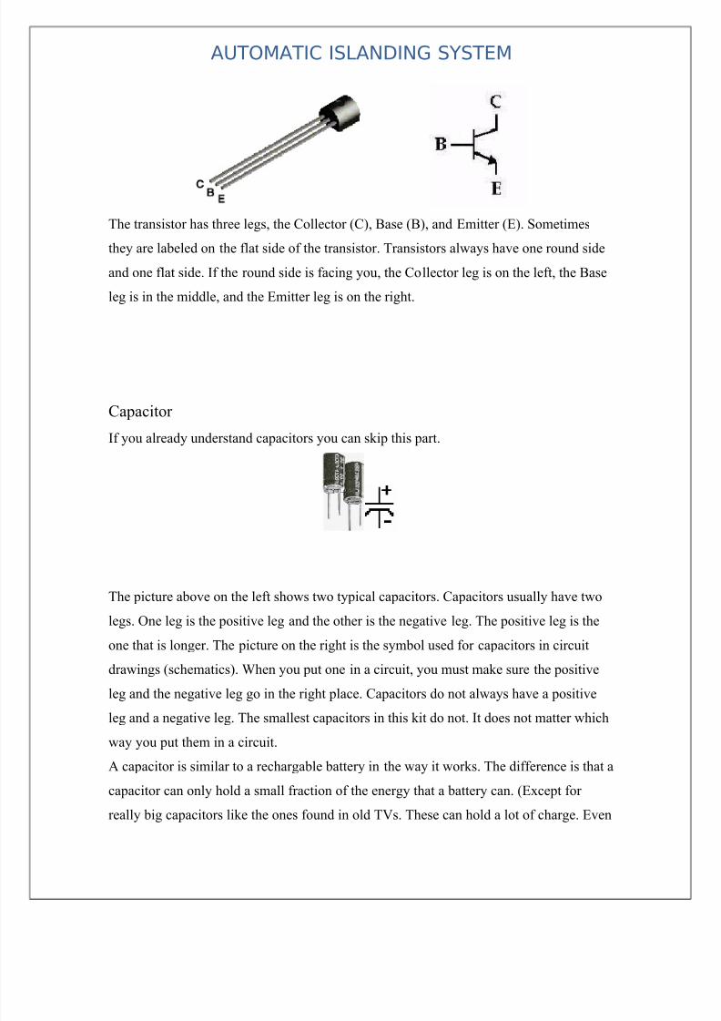
The transistor has three legs, the Collector (C), Base (B), and Emitter (E). Sometimes
they are labeled on the flat side of the transistor. Transistors always have one round side
and one flat side. If the round side is facing you, the Collector leg is on the left, the Base
leg is in the middle, and the Emitter leg is on the right.
Capacitor
If you already understand capacitors you can skip this part.
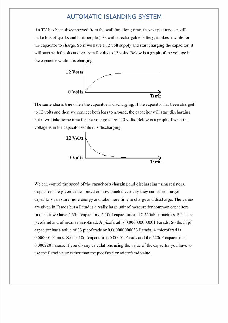
The picture above on the left shows two typical capacitors. Capacitors usually have two
legs. One leg is the positive leg and the other is the negative leg. The positive leg is the
one that is longer. The picture on the right is the symbol used for capacitors in circuit
drawings (schematics). When you put one in a circuit, you must make sure the positive
leg and the negative leg go in the right place. Capacitors do not always have a positive
leg and a negative leg. The smallest capacitors in this kit do not. It does not matter which
way you put them in a circuit.
A capacitor is similar to a rechargable battery in the way it works. The difference is that a
capacitor can only hold a small fraction of the energy that a battery can. (Except for
really big capacitors like the ones found in old TVs. These can hold a lot of charge. Even
7/28/2019 project report on Islanding System
http://slidepdf.com/reader/full/project-report-on-islanding-system 13/63
AUTOMATIC ISLANDING SYSTEM
if a TV has been disconnected from the wall for a long time, these capacitors can still
make lots of sparks and hurt people.) As with a rechargable battery, it takes a while for
the capacitor to charge. So if we have a 12 volt supply and start charging the capacitor, it
will start with 0 volts and go from 0 volts to 12 volts. Below is a graph of the voltage in
the capacitor while it is charging.
The same idea is true when the capacitor is discharging. If the capacitor has been charged
to 12 volts and then we connect both legs to ground, the capacitor will start discharging but it will take some time for the voltage to go to 0 volts. Below is a graph of what the
voltage is in the capacitor while it is discharging.
We can control the speed of the capacitor's charging and discharging using resistors.
Capacitors are given values based on how much electricity they can store. Larger
capacitors can store more energy and take more time to charge and discharge. The values
are given in Farads but a Farad is a really large unit of measure for common capacitors.
In this kit we have 2 33pf capacitors, 2 10uf capacitors and 2 220uF capacitors. Pf means
picofarad and uf means microfarad. A picofarad is 0.000000000001 Farads. So the 33pf
capacitor has a value of 33 picofarads or 0.000000000033 Farads. A microfarad is
0.000001 Farads. So the 10uf capacitor is 0.00001 Farads and the 220uF capacitor is
0.000220 Farads. If you do any calculations using the value of the capacitor you have to
use the Farad value rather than the picofarad or microfarad value.

7/28/2019 project report on Islanding System
http://slidepdf.com/reader/full/project-report-on-islanding-system 14/63
AUTOMATIC ISLANDING SYSTEM
Capacitors are also rated by the maximum voltage they can take. This value is always
written on the larger can shaped capacitors. For example, the 220uF capacitors in this kit
have a maximum voltage rating of 25 volts. If you apply more than 25 volts to them they
will die. We don’t have to worry about that with this kit because our power supply can
only put out 12 volts.
Voltage regulator
Most digital logic circuits and processors need a 5 volt power supply. To use these parts
we need to build a regulated 5 volt source. Usually you start with an unregulated power
supply ranging from 9 volts to 24 volts DC. To make a 5 volt power supply, we use a
LM7805 voltage regulator IC (Integrated Circuit). The IC is shown below.
The LM7805 is simple to use. You simply connect the positive lead of your unregulated
DC power supply (anything from 9VDC to 24VDC) to the Input pin, connect the
negative lead to the Ground pin and then when you turn on the power, you get a 5 volt
supply from the Output pin. This 5 volt output will be used as Vcc in the following
projects.
Connect the red wire from the power supply adapter to the input of the 7805. Connect the
black wire from the power supply adapter to the ground row (with the blue line beside it).
Run a black jumper wire from the ground row to the ground of the 7805. Then use a
yellow jumper to connect the 5 volt output to the row of holes with the red stripe beside
it. The breadboarded circuit is shown below.

7/28/2019 project report on Islanding System
http://slidepdf.com/reader/full/project-report-on-islanding-system 15/63
AUTOMATIC ISLANDING SYSTEM
Sometimes the input supply line (the 12VDC above) may be noisy. To help smooth out
this noise and get a better 5 volt output, a capacitor is usually added to the circuit, going
between the input and ground (GND). Find the 220 uF capacitor and put the long leg
(positive leg) in the row of holes with the 12VDC line and put the short leg (negative leg)
in ground (the row of holes next to the blue line).
Relay
The basis for relays, is the simple electromagnet Connect this to a power
source, and it will now grab and hold small pieces of metal. So, herein lies
the concept. If we take an electromagnet, it will interact with metals in its
vicinity. now lets take this one step further... If we were to place a piece of
metal, near the electromagnet, and connect some contacts, so that
The simplest relay, is the Single Pole, Single Throw (spst) relay. It is
nothing more than an electrically controlled on-off switch. It's biggest
property, is the ability to use a very small current, to control a much larger
current. this is desireable because we can now use smaller diameter wires, to
control the current flow through a much larger wire, and also to limit the
wear and tear on the control switch.
7/28/2019 project report on Islanding System
http://slidepdf.com/reader/full/project-report-on-islanding-system 16/63
AUTOMATIC ISLANDING SYSTEM
Bread board
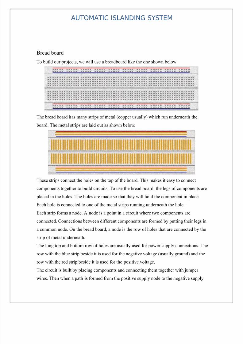
To build our projects, we will use a breadboard like the one shown below.
The bread board has many strips of metal (copper usually) which run underneath the
board. The metal strips are laid out as shown below.
These strips connect the holes on the top of the board. This makes it easy to connect
components together to build circuits. To use the bread board, the legs of components are
placed in the holes. The holes are made so that they will hold the component in place.
Each hole is connected to one of the metal strips running underneath the hole.
Each strip forms a node. A node is a point in a circuit where two components are
connected. Connections between different components are formed by putting their legs in
a common node. On the bread board, a node is the row of holes that are connected by the
strip of metal underneath.
The long top and bottom row of holes are usually used for power supply connections. The
row with the blue strip beside it is used for the negative voltage (usually ground) and the
row with the red strip beside it is used for the positive voltage.
The circuit is built by placing components and connecting them together with jumper
wires. Then when a path is formed from the positive supply node to the negative supply

7/28/2019 project report on Islanding System
http://slidepdf.com/reader/full/project-report-on-islanding-system 17/63

7/28/2019 project report on Islanding System
http://slidepdf.com/reader/full/project-report-on-islanding-system 18/63
AUTOMATIC ISLANDING SYSTEM

7/28/2019 project report on Islanding System
http://slidepdf.com/reader/full/project-report-on-islanding-system 19/63
AUTOMATIC ISLANDING SYSTEM
Block diagram:
LOAD CONTROL BLOCK DIAGRAM
Power Grid
Cutout
Frequency FastResponseMicrocontroller
Load LineTripper Relay
Display
Frequency
LOAD
Grid Line
Input
Microcontroller
Power Supply
Clock, Reset
LCD Display
RelayDriver IC
Relay,Buzzer
FrequencyUP Button
FrequencyDown button

7/28/2019 project report on Islanding System
http://slidepdf.com/reader/full/project-report-on-islanding-system 20/63
AUTOMATIC ISLANDING SYSTEM

7/28/2019 project report on Islanding System
http://slidepdf.com/reader/full/project-report-on-islanding-system 21/63
AUTOMATIC ISLANDING SYSTEM

7/28/2019 project report on Islanding System
http://slidepdf.com/reader/full/project-report-on-islanding-system 22/63
AUTOMATIC ISLANDING SYSTEM
7/28/2019 project report on Islanding System
http://slidepdf.com/reader/full/project-report-on-islanding-system 23/63
AUTOMATIC ISLANDING SYSTEM

7/28/2019 project report on Islanding System
http://slidepdf.com/reader/full/project-report-on-islanding-system 24/63
AUTOMATIC ISLANDING SYSTEM
Power Supply
There are many types of power supply. Most are designed to convert high
voltage AC mains electricity to a suitable low voltage supply for electronic
circuits and other devices. A power supply can by broken down into a series
of blocks, each of which performs a particular function.
For example a 5V regulated supply:
Each of the blocks is described in more detail below:
− Transformer - steps down high voltage AC mains to low voltage AC.
− Rectifier - converts AC to DC, but the DC output is varying.
− Smoothing - smoothes the DC from varying greatly to a small ripple.
− Regulator - eliminates ripple by setting DC output to a fixed voltage.
Power supplies made from these blocks are described below with a circuit
diagram and a graph of their output:
− Transformer only
− Transformer + Rectifier
− Transformer + Rectifier + Smoothing
− Transformer + Rectifier + Smoothing + Regulator
7/28/2019 project report on Islanding System
http://slidepdf.com/reader/full/project-report-on-islanding-system 25/63
AUTOMATIC ISLANDING SYSTEM
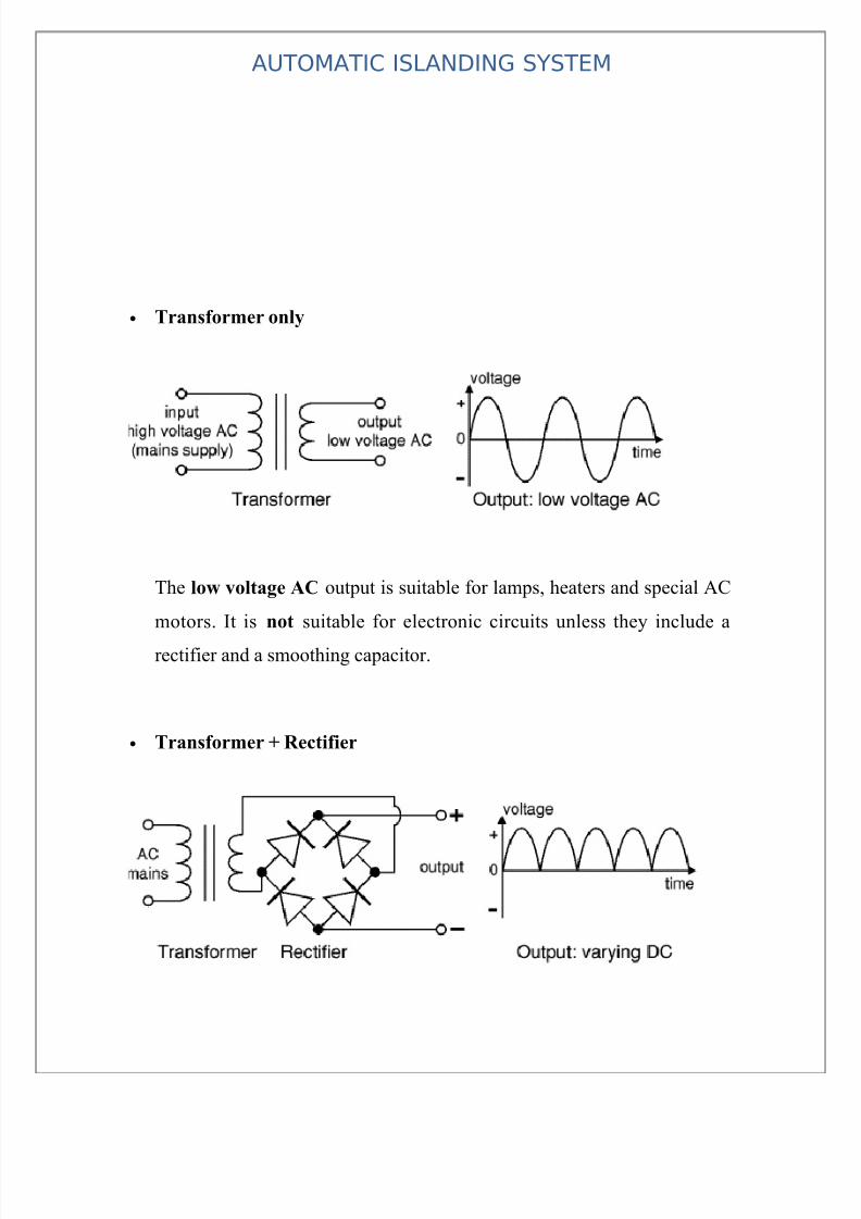
• Transformer only
The low voltage AC output is suitable for lamps, heaters and special AC
motors. It is not suitable for electronic circuits unless they include a
rectifier and a smoothing capacitor.
• Transformer + Rectifier
7/28/2019 project report on Islanding System
http://slidepdf.com/reader/full/project-report-on-islanding-system 26/63
AUTOMATIC ISLANDING SYSTEM
The varying DC output is suitable for lamps, heaters and standard
motors. It is not suitable for electronic circuits unless they include a
smoothing capacitor.
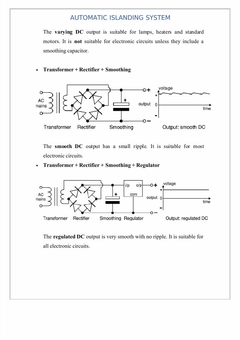
• Transformer + Rectifier + Smoothing
The smooth DC output has a small ripple. It is suitable for most
electronic circuits.
• Transformer + Rectifier + Smoothing + Regulator
The regulated DC output is very smooth with no ripple. It is suitable for all electronic circuits.

7/28/2019 project report on Islanding System
http://slidepdf.com/reader/full/project-report-on-islanding-system 27/63
AUTOMATIC ISLANDING SYSTEM
The fig. above shows the circuit diagram of the power supply unit. This
block mainly consists of a two regulating IC 7805 and a bridge rectified
and it provides a regulated supply approximately 5V.
The transformer used in this circuit has secondary rating of 7.5V. The
main function of the transformer is to step down the AC voltage available
from the main. The main connections are given to its primary winding
through a switch connected to a phase line. The transformer provides a
7.5V AC output at its secondary terminals and the maximum current that
can be drawn form the transformer is 1 Amp which is well above therequired level for the circuit.
The bridge rectified the AC voltage available from the secondary of the
transformer, i.e. the bridge rectifier convert the AC power available into
DC power but this DC voltage available is not constant. It is a
unidirectional voltage with varying amplitude.
To regulate the voltage from the bridge rectifier, capacitors are
connected. Capacitors C1 filter the output voltage of the rectifier but their
output is not regulated and hence 7805 is connected which is specially
designed for this purpose.
Although voltage regulators can be designed using op-amps, it is quicker
and easier to use IC voltage regulator. Further more, IC voltage
regulators are available with features such as programmable output
current/ voltage boosting, internal short circuit current limiting, thermal
shut down and floating operation for high voltage applications.

7/28/2019 project report on Islanding System
http://slidepdf.com/reader/full/project-report-on-islanding-system 28/63
AUTOMATIC ISLANDING SYSTEM
The 78 XX series consists of three terminals viz, input, output & ground.
This is a group of fixed positive voltage regulator to give and output
voltage ranging form 5V to 24V. These IC’s are designed as fixed
voltage regulators and with adequate heat sinking, can delivery output
current in excess of 1 Amp although these devices do not require external
components and such components can be used to obtain adjustable
voltage and current limiting. In addition, the difference between the input
and output voltages (V in Vo) called the dropout voltage must be
typically 2V even from a power supply filter. Capacitors C2, C3, C4, and
C5 are small filters which are used for extra filtering.LED1& LED2 areused for Power ON indicator for IC1 and IC2, current-limiting resistors
R2&R4, which prevents the LED’s from getting heated and thus
damaged.
7/28/2019 project report on Islanding System
http://slidepdf.com/reader/full/project-report-on-islanding-system 29/63
AUTOMATIC ISLANDING SYSTEM

7/28/2019 project report on Islanding System
http://slidepdf.com/reader/full/project-report-on-islanding-system 30/63
AUTOMATIC ISLANDING SYSTEM
Working Of Circuit
1)Conversion Of Power
[1]Power is taken from main’s using main scord.It is step down using step down
Transformer of 230V
AC to 12V AC,1amp for working of circuit.The actual circuit which consist of
Microcontroller uses +5V.
The step down 12V AC is converted to DC using bridge rectifier 4 diode (4007) is used
for higher accuracy.
[2]This DC power consist of very much variation so filter circuit is used to act pure DC
for this 1000µf (16V) capacitor is used.
[3]This voltage is then regulated for better operation using IC7805 (+5V) with 10µf
capacitor to filter the circuit.
[4]The circuit working is showed by LED.This is current limiting LED(3.3V) with
current limiting resistor (1KΩ) in series with LED.This is actually parallel with 0.1µf
capacitor.This type of capacitor are used across every electronics parts for pure DC
2)Microcontroller working/action
1]Microcontroller (89S51) has 40 pins,which are divided into
power(Vcc),Ground,Reset,2 pin for clock frequency and other pins are divided into
port0,port1,port2,port3.
2]LCD is used for displaying frequency of supply.It is connected in port0 of which 1pin
is Vcc,2nd pin is ground,6 pin for control & 4 pin for data in which data of 4bit is sent
twice serially.Therefore LCD is (16X2) 16 pin IC which brightness can be controlled by
preset.
3]Pull up resistor is connected in series whose value is (10kΩ) is used to match frequency
of LCD to the frequency of Microcontroller.
4]Push button are connected in port1 where up button is connected to Vcc and down
button is connected to ground. So there is input signal for changing frequency of
Microcontroller.

7/28/2019 project report on Islanding System
http://slidepdf.com/reader/full/project-report-on-islanding-system 31/63
AUTOMATIC ISLANDING SYSTEM
5]Relay are used for connecting the load to supply.Relay works on +12V supply,so it is
directly connected from output of filter.The relay is connected across 3.3V LED with
series 1kΩ resistor to indicate working of relay.
(6) Relay is triggered using Transistor. Transistor base is connected to microcontroller.
This transistor are packed in single IC ULN2803 for reducing size of PCB.
(7) Reset is connected with pin9 with parallel in 10 uf. Capacitor & 10 Kohm resistance
in parallel. It keeps ckt on when ever it is started again.
(8) Oscillator provides clock frequency which has 11.0592 MHZ frequency. This value is
choosed because it is between working frequency (4 MHZ-18MHZ) of microcontroller.
This is connected with 22 PF capacitor to pin 18 & 19 in parallel at port3. This oscillator
is very essential for proper working of ckt.
(9) Load is connected to baby bulb holder where input is directly from main’s cord
(230v). The total 4 load are connected in parallel where relay are used as a switch for
controlling load

7/28/2019 project report on Islanding System
http://slidepdf.com/reader/full/project-report-on-islanding-system 32/63
AUTOMATIC ISLANDING SYSTEM

7/28/2019 project report on Islanding System
http://slidepdf.com/reader/full/project-report-on-islanding-system 33/63
AUTOMATIC ISLANDING SYSTEM
SOFTWARE PROJECT MANAGEMENT PLAN
1. INTRODUCTION
1.1 Project Deliverables
The following are the deliverables of the Project:
1. GUIs made using Microsoft Visual Studio
2. Database using Microsoft Access
3. Executable Files.
4. DLL Files.
5. Help Files.
.
2 PROJECT ORGANIZATION
2.1 Software Process Model
The model used is Classic Life Cycle Model
• The Project team is meeting once a week to discuss the progress made by each
member and to share the relevant information and be documents that have been prepared.
The number of meetings may increase during the final semester as the team members will
have more time.
• There are reviews being conducted once a week during the team meetings. A
complete technical review will be conducted at the end of the Design Phase. There will
be reviews conducted at the completion of every testing phase.
• The major milestones to be achieved are as follows:
1. Results of research of existing system and discussions with the Project
leader.

7/28/2019 project report on Islanding System
http://slidepdf.com/reader/full/project-report-on-islanding-system 34/63
AUTOMATIC ISLANDING SYSTEM
2. Results of interview with experts and team meetings to finalize the
requirements of the software.
3. Results of the Design Phase, which include a number of modeling
diagrams, like the use cases, class diagrams, etc.
4. Results of the first coding phase will be an initial code that will be then
tested.
5. Based on the results of the testing, they code will be reviewed in the
second coding phase.
2.2 Tools and Techniques
We will require the following tools:
1. Microsoft Visual Studio 2005.
2. Microsoft Office 2003.
3 PROJECT MANAGEMENT PLAN
3.1 TasksThe following tasks are to be executed:-
1. Requirement Analysis Phase 1
2. Requirement Analysis Phase 2
3. Design of System
4. Coding Phase 1
5. Coding Phase 2
6. Testing Phase 1
Requirement analysis:
1. Requirement Analysis Phase 1 : This will include the research of existing
software and a discussion with the Project guide.

7/28/2019 project report on Islanding System
http://slidepdf.com/reader/full/project-report-on-islanding-system 35/63
AUTOMATIC ISLANDING SYSTEM
Requirement Analysis Phase 2: Based on the above results, the project team will discuss
and finalize the requirements that are to be provided. We shall consult a number of
experts during this phase. The SPMP shall also be prepared during this phase.
Design Phase: The design phase will involve the design of the static view, dynamic view,
and the functional view of the software. A number of diagrams including the Use case,
class diagram, activity diagram, and data flow diagrams will be used to model the
software. Also, the GUIs will be designed during this phase
Coding Phase 1: The prerequisite to this phase is the study of Microsoft Visual basic6.
After this study, an initial code of the entire project will be written. Also, the database
will be created during this phase. Finally, we shall conduct unit tests.
Coding Phase 2: This phase will include a review of the code created in Phase 1. After
the review, the necessary code and database will be modified to include the results of
review.
Testing Phase: We shall be following a testing program that will involve unit testing,
integration testing, and validation testing. More information will be known after further discussion.

7/28/2019 project report on Islanding System
http://slidepdf.com/reader/full/project-report-on-islanding-system 36/63
AUTOMATIC ISLANDING SYSTEM

7/28/2019 project report on Islanding System
http://slidepdf.com/reader/full/project-report-on-islanding-system 37/63
AUTOMATIC ISLANDING SYSTEM
Component List
SR.No Description Qty. Price
(Per
piece)1 Transformer 12-0-12V,750mA 1 60
2 Diode 1N4007 4 2
3 Capacitor1000uF,25V 1 5
4 Voltage regulator IC 7805 1 10
5 Capacitor 1uF 1 1
6 LED 1 1
7 Resistors 15 18 Disc capacitors 5 2
9 IC Base 5 3
10 PCB 1 250
11 Wires 2 15
12 Solder wire 1 25
13 Cabinet 1 150
14 Mains cord 1 10
15 Transistor BC548 5 316 IC 74244 1 25
17 Connector DB25 female 1 25
18 Connecting cord parallel port 1 50
19 Microcontroller 89S51 1 45
20 LCD (16x2) 1 180
21 Relay Contactor 4 35
22 Wood Ply 1 200
23 Transmission tower 2 2000
24 Lamp (100Watts) 4 30
25 MISC --------- 300

7/28/2019 project report on Islanding System
http://slidepdf.com/reader/full/project-report-on-islanding-system 38/63
AUTOMATIC ISLANDING SYSTEM

7/28/2019 project report on Islanding System
http://slidepdf.com/reader/full/project-report-on-islanding-system 39/63
AUTOMATIC ISLANDING SYSTEM
P.C.B. MAKING
P.C.B. is printed circuit board which is of insulating base with layer of thin copper-
foil.
The circuit diagram is then drawn on the P. C. B. with permanent marker and then it is
dipped in the solution of ferric chloride so that unwanted copper is removed from the
P.C.B., thus leaving components interconnection on the board.
The specification of the base material is not important to know in most of the application,
but it is important to know something about copper foil which is drawn through a thin
slip.
The resistance of copper foil will have an affect on the circuit operation.
Base material is made of lamination layer of suitable insulating material such as treated
paper, fabric; or glass fibers and binding them with resin. Most commonly used base
materials are formed paper bonded with epoxy resin.
It is possible to obtain a range of thickness between 0.5 mm to 3 mm.
Thickness is the important factor in determining mechanical strength particularly
when the commonly used base material is “Formea” from paper assembly.
Physical properties should be self supporting these are surface resistivity, heat
dissipation, dielectric, constant, dielectric strength.
Another important factor is the ability to wishstand high temperature.
DESIGNING THE LAYOUT :
While designing a layout, it must be noted that size of the board should be as small as
possible.Before starting, all components should be placed properly so that an accurate
measurement of space can be made.
The component should not be mounted very close to each other or far away from
one another and neither one should ignore the fact that some component reed ventilation,

7/28/2019 project report on Islanding System
http://slidepdf.com/reader/full/project-report-on-islanding-system 40/63
AUTOMATIC ISLANDING SYSTEM
which considerely the dimension of the relay and transformer in view of arrangement, the
bolting arrangement is also considered.
The layout is first drawn on paper then traced on copper plate which is finalized with the
pen or permanent marker which is efficient and clean with etching.
The resistivity also depends on the purity of copper, which is highest for low purity of
copper. The high resistance path are always undesired for soldered connections.
The most difficult part of making an original printed circuit is the conversion from,
theretical circuit diagram into wiring layout. without introducing cross over and
undesirable effect.
Although it is difficult operation, it provides greatent amount of satisfaction because it is
carried out with more care and skill.
The board used for project has copper foil thickness in the range of 25 40 75 microns.
The soldering quality requires 99.99% efficiency.
It is necessary to design copper path extra large. There are two main reasons for this,
(1) The copper may be required to carry an extra large overall current
(2) It acts like a kind of screen or ground plane to minimize the effect of
interaction.
The first function is to connect the components together in their right sequence with
minimum need for interlinking i.e. the jumpers with wire connections.It must be noted, that when layout is done, on the next day it should be dipped in the
solution and board is move continuously right and left after etching perfectly the board is
cleaned with water and is drilled.
After that holes are drilled with 1 mm or 0.8 mm drill. Now the marker on the P. C. B. is
removed.
The Printed Circuit Board is now ready for mounting the components on it.

7/28/2019 project report on Islanding System
http://slidepdf.com/reader/full/project-report-on-islanding-system 41/63
AUTOMATIC ISLANDING SYSTEM
SOLDERING :
For soldering of any joints first the terminal to be soldered are cleaned to remove oxide
film or dirt on it. If required flux is applied on the points to be soldered.
Now the joint to be soldered is heated with the help of soldering iron. Heat applied
should be such that when solder wire is touched to joint, it must melt quickly.
The joint and the soldering iron is held such that molten solder should flow smoothly
over the joint.
When joint is completely covered with molten solder, the soldering iron is removed.
The joint is allowed to cool, without any movement.
The bright shining solder indicates good soldering.
In case of dry solder joint, a air gap remains in between the solder matenal and the joint.
It means that soldering is improper. This is removed and again soldering is done.
Thus is this way all the components are soldered on P. C. B.

7/28/2019 project report on Islanding System
http://slidepdf.com/reader/full/project-report-on-islanding-system 42/63
AUTOMATIC ISLANDING SYSTEM

7/28/2019 project report on Islanding System
http://slidepdf.com/reader/full/project-report-on-islanding-system 43/63
AUTOMATIC ISLANDING SYSTEM
Advantages
(1) It will never let the grid to fail
(2) It is reliable
(3) It gives fast response because of use of microcontroller
(4) It will prevent huge loss in the grid
(5) system alerts us from change in load variation & frequency variation

7/28/2019 project report on Islanding System
http://slidepdf.com/reader/full/project-report-on-islanding-system 44/63
AUTOMATIC ISLANDING SYSTEM

7/28/2019 project report on Islanding System
http://slidepdf.com/reader/full/project-report-on-islanding-system 45/63
AUTOMATIC ISLANDING SYSTEM
Application
(1) It is used in grid
(2) It is used for controlling during peak load period
(3) It can also be used for industrial purpose
(4) It can be used in a system which require high accuracy

7/28/2019 project report on Islanding System
http://slidepdf.com/reader/full/project-report-on-islanding-system 46/63
AUTOMATIC ISLANDING SYSTEM
7/28/2019 project report on Islanding System
http://slidepdf.com/reader/full/project-report-on-islanding-system 47/63
AUTOMATIC ISLANDING SYSTEM
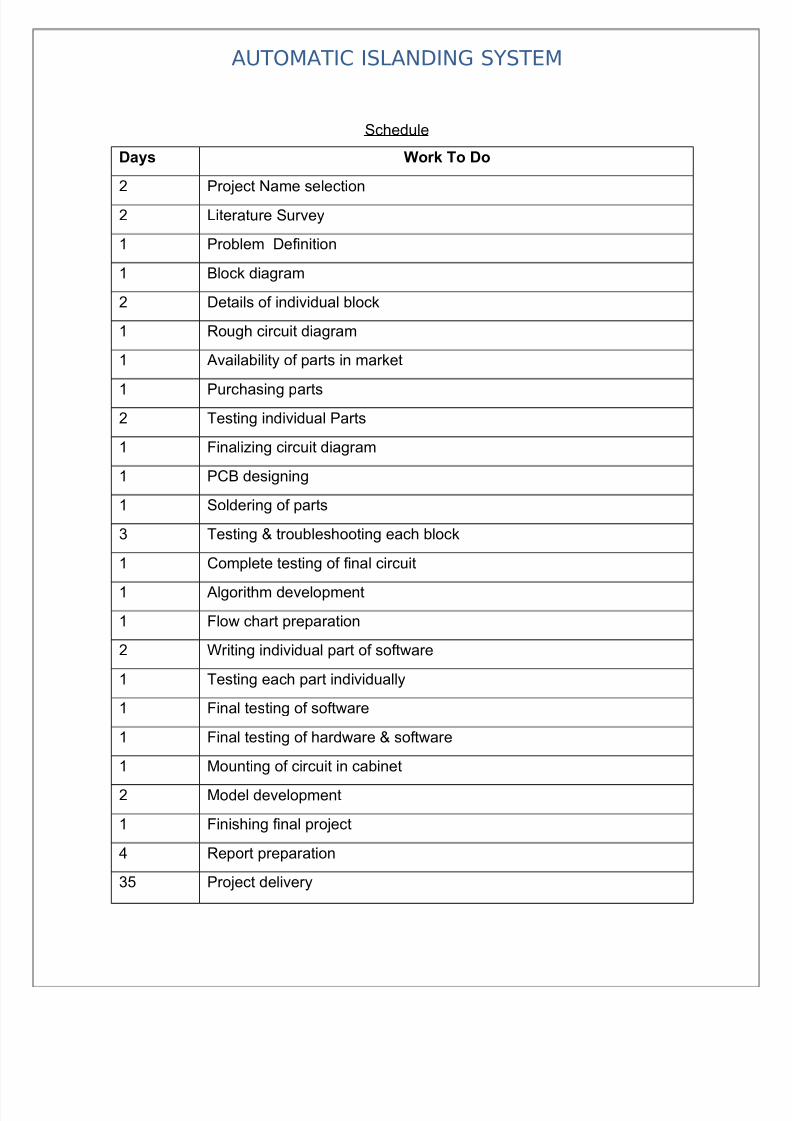
Schedule
Days Work To Do
2 Project Name selection
2 Literature Survey
1 Problem Definition
1 Block diagram
2 Details of individual block
1 Rough circuit diagram
1 Availability of parts in market
1 Purchasing parts
2 Testing individual Parts
1 Finalizing circuit diagram
1 PCB designing
1 Soldering of parts
3 Testing & troubleshooting each block
1 Complete testing of final circuit
1 Algorithm development
1 Flow chart preparation
2 Writing individual part of software
1 Testing each part individually
1 Final testing of software
1 Final testing of hardware & software
1 Mounting of circuit in cabinet
2 Model development
1 Finishing final project
4 Report preparation
35 Project delivery

7/28/2019 project report on Islanding System
http://slidepdf.com/reader/full/project-report-on-islanding-system 48/63
AUTOMATIC ISLANDING SYSTEM
DEVELOPMENT STAGES & PROCESS
The complete development of this system can be divided into the followingstages:
• Problem definition stage;
• Designing block diagram;
• Implementing circuits and components;
• Developing algorithm for software;
• Writing actual code for Microcontroller;
• Compiling the code;
• Burning the hex file into microcontroller with programmer;
• Testing and Running.
• Problem definition stage
This is the very first stage to develop any project. It actually defines the
aim and the concept of the project. The aim of “Microcontroller Based
Data Acquisition and Controlling System with PC interface” is to
design a DAS which can be connected to any type of computer serial port
giving the user flexibility of selection of desired number of channels for
data acquisition with least complexity and cost.
• Designing block diagram
At this stage we have categorized the whole system into different
individual modules. These modules (block diagrams) will be helpful in

7/28/2019 project report on Islanding System
http://slidepdf.com/reader/full/project-report-on-islanding-system 49/63
AUTOMATIC ISLANDING SYSTEM
understanding the concept and working of the integrated system. It also
simplifies the entire debugging and testing process.
• Implementing circuits and components
This is the actual implementation of circuit of each block. At this stage
we have actually designed each block separately and finally integrated
them into the complete working system.
• Developing algorithm for software
To get the logical flow of the software, the development of algorithm is
having a prominent role. So that we have analyzed the complete system
and organized the algorithm in such a manner that one can understand the
complete working of the software.
• writing actual code for Microcontroller
After the development of the algorithm and flowchart we have actuallytranslated them in C language for Atmel 89C51 Microcontroller so that it
can understand the instructions and run as per our requirement. The
instructions are in ANSII C Language.
• Compiling the code
The code is implemented on the computer for which we have used Keil
pre-installed on PC. The Keil is a Computer Aided Program to simulate
the working of Microcontroller in real time without burning the software
into actual IC. We simulated and compiled our program for error

7/28/2019 project report on Islanding System
http://slidepdf.com/reader/full/project-report-on-islanding-system 50/63
AUTOMATIC ISLANDING SYSTEM
checking. After removing of several compiling errors the program was
converted into machine language i.e. Intel hex format.
• Burning the hex file into microcontroller with Programmer
In this stage the compiled hex format file was downloaded or burned into
Atmel AT89C51 flash Microcontroller. This was done with the help of
FP-8903 Programmer for Atmel microcontrollers designed by Oriole
Electronics Pvt. Ltd.
• Testing and Running
This time we tested our project for actual working, after loading the
software into the microcontroller. Any errors found were removed
successfully. This is the last and final stage of development of our
project.

7/28/2019 project report on Islanding System
http://slidepdf.com/reader/full/project-report-on-islanding-system 51/63
AUTOMATIC ISLANDING SYSTEM

7/28/2019 project report on Islanding System
http://slidepdf.com/reader/full/project-report-on-islanding-system 52/63
AUTOMATIC ISLANDING SYSTEM
Testing & Troubleshooting
Before you apply power, read the instructions carefully to check you haven't missed
anything, and whether there are any specific instructions for switching on and testing.
Check again that you have all polarity sensitive components the right way around, and
that all components are in the correct places. Check off - board components are
connected correctly. Check the underside of the board carefully for short circuits between
tracks - a common reason for circuits failing to work.
When you are sure everything is correct, apply power and see if the circuit behaves as
expected, again following the kit manufacturer’s instructions.
If it works, WELL DONE! You have your first working circuit - be proud of it! Skip the
rest of this page and click the right arrow at the bottom, or here.
If it doesn't quite work as expected, or doesn't work at all, don't despair. The chances are
the fault is quite simple. However, disconnect the power before reading on.
Check the basic's first - is the battery flat? Are you sure the 'On' switch really is on?
(Don't laugh, it's easily done) If the project has other switches and controls check these
are set correctly.
Next - check again all the components are in the correct place - refer to the diagram in the
instructions. Look again at the underside of the board - are there any short circuits? These
can be caused by almost invisible 'whiskers' of solder, so check for these with a
magnifying glass in good light. Brushing the bottom of the board vigorously with a stiff
brush can sometimes remove these.
Pull the components gently to see if they are all fixed into the board properly. Check the
soldered joints - poor soldering is the most common cause of circuits failing to work. The
joints should by shiny, and those on the circuit board should be volcano shaped with the

7/28/2019 project report on Islanding System
http://slidepdf.com/reader/full/project-report-on-islanding-system 53/63
AUTOMATIC ISLANDING SYSTEM
component wire end sticking out of the top. If any look suspect then redo them. Remove
the solder with a solder sucker or braid and try again.
Check for solder splashes shorting across adjacent tracks on the circuit board, especially
where connections are very close such as on integrated circuits ('chips'). Solder splashes
are most likely on stripboard. You can check for shorts using a multimeter set it to it's
continuity range, or low resistance range. Be aware if you do this though, that there will
be a resistance between some tracks due to the components. Any resistance below 1 ohm
between tracks is likely to be a solder splash. Run the soldering iron between tracks on
stripboard to remove any solder bridges.
If the circuit still fails to work you will need to refer to the circuit diagram and take
voltage readings from the circuit to find out what's wrong. You will need a multimeter to
do this (see tools). Remember that if you find one fault such as a reversed component and
correct it, it might have caused damage to other components.
Beginners Guide - More Tools & Test Equipment
To design your own circuits, or build more complex kits, you will probably need more in
the way of tools and test equipment. If you did not buy a multimeter before then this isessential now, a basic power supply is also very useful. More expensive items such as an
oscilloscope can be useful, but think carefully about whether you really need them - after
all, you can build a lot of projects for the price of an oscilloscope. PC-based virtual
instruments could perhaps be more suitable. Other tools can be useful too.
Here is a list of other useful items, although this by no means covers all the tools and
equipment available. Maplin codes are included, however similar items are available
from most suppliers.

7/28/2019 project report on Islanding System
http://slidepdf.com/reader/full/project-report-on-islanding-system 54/63
AUTOMATIC ISLANDING SYSTEM
Test Equipment:
Multimeter - almost essential for all but the absolute beginner. See the tools section for
more information.
Power Supply - Also very useful for powering circuits that you are testing. One with a
variable voltage up to at least 12V is best. The current rating doesn't need to be that high,
1A maximum is fine for most jobs. If you can afford it then one with an adjustable
current limit is useful - set right it can prevent damage to an incorrect circuit, rather than
frying it instantly!

7/28/2019 project report on Islanding System
http://slidepdf.com/reader/full/project-report-on-islanding-system 55/63
AUTOMATIC ISLANDING SYSTEM

7/28/2019 project report on Islanding System
http://slidepdf.com/reader/full/project-report-on-islanding-system 56/63
AUTOMATIC ISLANDING SYSTEM
Bibiliography
1. Basic Electronics – B.Ram
2. Digital Electronics – R.P.Jain
3. www.redcircuits.com
4 www.alldatasheet.com.
5.www.elctronicsforu.com

7/28/2019 project report on Islanding System
http://slidepdf.com/reader/full/project-report-on-islanding-system 57/63
AUTOMATIC ISLANDING SYSTEM

7/28/2019 project report on Islanding System
http://slidepdf.com/reader/full/project-report-on-islanding-system 58/63
AUTOMATIC ISLANDING SYSTEM

7/28/2019 project report on Islanding System
http://slidepdf.com/reader/full/project-report-on-islanding-system 59/63
AUTOMATIC ISLANDING SYSTEM

7/28/2019 project report on Islanding System
http://slidepdf.com/reader/full/project-report-on-islanding-system 60/63
AUTOMATIC ISLANDING SYSTEM

7/28/2019 project report on Islanding System
http://slidepdf.com/reader/full/project-report-on-islanding-system 61/63
AUTOMATIC ISLANDING SYSTEM

7/28/2019 project report on Islanding System
http://slidepdf.com/reader/full/project-report-on-islanding-system 62/63
AUTOMATIC ISLANDING SYSTEM

7/28/2019 project report on Islanding System
http://slidepdf.com/reader/full/project-report-on-islanding-system 63/63
AUTOMATIC ISLANDING SYSTEM