Embed Size (px)
Citation preview
I .
NORTHERN KENTUCKY WATER DISTRICT
Project Taylor Mill Treatment Plant
Advanced Treatment Improvements
Kenton County 184-0457

NORTHERN KENTUCKY WATER DISTRICT Taylor Mill Treatment Plant Advanced Treatment Improvements
184-457
EXHIBIT
A
B
C
o
E
F
G
TABLE OF CONTENTS
TITLE
ENGINEERING REPORTS AND INFORMATION Project map, Basis of Design Report; Engineer's opinion of probable total construction cost; plans titled "Taylor Mill Treatment Plant Advanced Treatment Improvements" dated March 2011, sealed by a P.E.; specifications titled 'Taylor Mill Treatment Plant Advanced Treatment Improvements" dated March 2011 and sealed by a P.E.
Certified statement from an authorized utility Official confirming:
(1) Affidavit
(2) Franchises
(3) Plan review and permit status
(4) Easements and Right-Ot-Way status
(5) Construction dates and proposed date in service
(6) Plant retirements
BID INFORMATION AND BOARD RESOLUTION Bid tabulation, Engineer's recommendation ot award, Board resolution.
PROJECT FINANCE INFORMATION Customers added and revenue effect, Debt issuance and source of debt, Additional costs and operating and maintenance, USoA plant account, Depreciation cost and debt service after construction.
PSC ANNUAL REPORT - 2011
SCHEDULE OF MORTGAGES. BONDS, NOTES, AND OTHER INDEBTEDNESS
CURRENT BALANCE SHEET AND INCOME STATEMENT

Project Description:
Taylor Mill Treatment Plant Advanced Treatment Improvements
Project 184-457
The project involves the construction of a new concrete and masonry brick building that houses the Preliminary Treatment Building on one side and the Granular Activated Carbon Building on the other side. The new Preliminary Treatment Building will contain a rapid mix basin, 4 flocculation basins, and 2 sedimentation basins with plate settlers and residuals collection system. The new GAC building with a vegetative roof will house 14 granular activated carbon pressure vessels plus a smaller pump for backwashing the pressure vessels, and the relocation of 2 existing medium pressure ultraviolet disinfection reactors. The GAC Feed Pump Station consists of 3 vertical turbine pumps and variable speed drives along with electrical gear for two diesel driven standby power generators located adjacent to the GAC Feed Pump Station that will operate the entire treatment plant in a power loss. The project includes anciHary improvements such as a relocated operator's laboratory, control through the existing SCADA system, mechanical HV AC and plumbing systems, and electrical systems.
The bids will be opened May 3, 2011 and are subject to acceptance for 120 days. Therefore, the bids will expire August 31, 2011. The project is scheduled to take 31 months to substantial completion and another 2 months to reach final completion.
The estimated cost of the total project with engineering, construction, and contingencies is $35,000,000.

Case No. 2011-_ Exhibit A
NORTHERN KENTUCKY WATER DISTRICT
Project Taylor Mill Treatment Plant
Advanced Treatment Improvements
Kenton County 184-0457
/
ENGINEERING REPORTS AND INFORMATION
Project Map
Basis of Design Report
Engineer's Opinion of Probable Total Construction Cost
Plans prepared by Malcolm Pirnie, GRW, COP Engineers, and Strand Associates titled "Taylor Mill Treatment Plant Advanced Treatment Improvements" dated
March 2011
Specifications prepared by Malcolm Pirnie, GRW, COP Engineers, and Strand Associates titled "Taylor Mill Treatment Plant Advanced Treatment
Improvements" dated March 2011

NORTHERN KENTUCKY WATER DISTRICT
Project
Case No. 2011-_ Exhibit A
Tavlor Mill Treatment Plant Advanced Treatment Improvements
Kenton County 184-0457
Project Map

Taylor Mill Treatment Plant GAC Project

NORTHERN KENTUCKY WATER DISTRICT
Project
Case No. 2011-_ Exhibit _--'-"---___
Taylor Mill Treatment Plant Advanced Treatment Improvements
Kenton County 184-0457
Basis of Design Report

4775-012
Northern Kentucky Water District 2835 Crescent Springs Road • Erlanger KY 410108
Taylor Mill Advanced Treatment .Improvements Basis of Design Report
January 2009 Updated: March 2009
Report Prepared By:
Malcolm Plrnle, Inc. 8600 Governor's Hill Drive Suite 210 Cincinnati OH 45249
MALCOLM PIRNIE

•
•
•
Table of Contents
Contents
Executive Summary ES-1
ES.1.0verview ..................................................................................................................... ES-1
ES.2. Project Driver ............................................................................................................. ES-1
ES.3. Pretreatment Facilities ............................................................................................... ES-1
ES.4. GAC Facilities........... ............. ...................................... ................... . ...................... ES-2
ES.S.Opinion of Probable Project Costs ............................................................................. ES-2
1. Introduction 1·1
1 .1. General...................................................................................... . .............................. 1-1
1.2. Organization .................................................................................................................. 1-1
1.3. Facilities ......................................................................................................................... 1-2
2. Site/Civil 2-1
2.1. Introduction .................................................................................................................... 2-1
2.2. Design Approach ........................................................................................................... 2-2
2.3. Materials ................................................................................................ . ................. 2-3
2.4. References .................................................................................................................... 2-3
2.5. Miscellaneous ................................................................................................................ 2-4
3. Architectural 3-1
3.1. Introduction .................................................................................................................... 3-1
3.2. Design Approach .......... ......... .. ......................................................................... 3-1 3.2.1. Preliminary Treatment Building ...................................................................... 3-.1 3.2.2. GAC Building ................................................................................................. 3-2 3.2.3. GAC Feed Pump Station ....... .... ............. ............. ...... . .. ......................... 3-2
3.3. Materials, Equipment and Systems ............................................................................... 3-3 3.3.1. Interior Materials ..................................................... : ...................................... 3-3 3.3.2. Exterior Materials ................................................... : ....................................... 3-3
3.4. References .................................................................................................................... 3-3
3.5. Miscellaneous......... ............. ...................................................................... .. .............. 3-4
4. Structural 4-1
4.1. Introduction .................................................................................................................... 4-1
4.2. Design Approach ........................................................................................................... 4-1
4.3. Facilities ......................................................................................................................... 4-1 4.3.1. Preliminary Treatment Facilities .................................................... : ............... 4-1 4.3.2. GAC Feed Pump Station .............................................................................. .4-1 4.3.3. GAC Building ................................................................................................. 4-1 4.3.4. Backwash Equalization Basin ........................................................................ 4-1 4.3.5. Existing Tunnel .............................................................................................. 4-1
•.• Q... -- Northern Kentucky Water District
Taylor Mill Advanced Treatment Improvements Basis of Design Report 4775-012
•
•
•
Table of Contents
4.4. Materials ........................................................................................................................ 4-2 4.4.1. Concrete .............................................................................. : ......................... 4-2 4.4.2. Reinforcement ................................................................................................ 4-2 4.4.3. Steel................................................... .. ...................................................... 4-2 4.4.4. Stainless Steel ............................................................................................... 4-3 4.4.5. Aluminum ....................................................................................................... 4-3
4.5. DeSign Criteria ............................................................................................................... 4-3
4.6. References .................. .. ......................................................................... 4-6 4.6.1. Building Code ................................................................................................. 4-6 4.6.2. Codes and Standards .................................................................................... 4-6
4.7. Miscellaneous ................................................................................................................ 4-7 4.7.1. EXisting Conditions ........................................................................................ 4-7 4.7.2. Leadership in Energy and Environmental Design (LEE D) Goals ................. .4-7 4.7.3. Geotechnical Information .............................................................................. 4-7
5. Process Mechanical 5·1 5.1. Introduction ................................................ , ................................................................... 5-1
5.2. Design Approach ........................................................................................................... 5-2 5.2.1. General .......................................................................................................... 5-2 5.2.2. Preliminary Treatment Facilities .................................................................... 5-2
5.2.2.1. Rapid Mix .................................................................................. 5-2 5.2.2.2. Flocculation ............................................................................... 5-3 5.2.2.3. Sedimentation .......................................................................... 5-5
5.2.3. GAC Treatment Facilities ............................................................................... 5-7 5.2.3.1. GAC Feed Pump Station .......................................................... 5-7 5.2.3.2. GAC Building ............................................................................. 5-9 5.2.3.3. GAC Equalization Basin .......................................................... 5-15
5.3. Materials, EqUipment, and Systems ............................................................................ 5-16 5.3.1. Materials of Construction ............................................................................. 5-16 5.3.2. Equipment ....... .......... .... .................... .. ............................................. 5-17
6. HVAC 6·1 6.1 . Introduction ............ " ......................... .. .. ........................................... 6-1
6.2. Design Approach ........................................................................................................... 6-1
6.3. Facilities ......................................................................................................................... 6-1 6.3.1. Proposed Preliminary Treatment Building ..................................................... 6-1 6.3.2. Proposed GAC Feed Pump Station ............................................................... 6-1 6.3.3. Proposed GAC Building ................................................................................. 6-1
6.4. Materials, Equipment and Systems ............................................................................... 6-2 6.4.1. Materials ........................................................................................................ 6-2 6.4.2. Equipment ...................................................................................................... 6-2 6.4.3. Systems ......................................................................................................... 6-3
6.5. DeSign Criteria ............................................................................................................... 6-3 6.5.1 . Miscellaneous Design Criteria ....................................................................... 6-3
6.5.1.1. Controls........................................... .. .... 6-3 6.5.1 .2. Louver Sizing ............................................................................ 6-4 6.5.1 .3. Ductwork Sizing ........................................................................ 6-4
6.6. References .................................................................................................................... 6-4 6.6.1. Codes ............................................................................................................. 6-4
c:;:;t.. -- Northern Kentucky Water District _ Taylor Mill Advanced Treatment Improvements Basis of Design Report 4775-012
ii

•
•
•
Table of Contents
6.6.2. Standards ....................................................................................................... 6-S
6.7. Miscellaneous ................................................................................................................ 6-S 6.7.1. Dehumidification ......................................................................................... :6-S 6.7.2. Calculation Software ...................................................................................... 6-S
7. Plumbing 7-1
7.1. Introduction .................................................................................................................... 7-1
7.2. Design Approach ........................................................................................................... 7-1 7.2.1. General .......................................................................................................... 7-1 7.2.2. Preliminary Treatment Building ...................................................................... 7-1 7.2.3. GAC FeedPump Station ............................................................................... 7-1 7.2.4. GAC Building ................................................................................................. 7-1 7.2.S. Design Criteria ............................................................................................... 7-3
7.3. Materials, Equipment and Systems ............................................................................... 7-4 7.3.1. Materials ........................................................................................................ 7-4 7.3.2. Equipment .......................... .. ...................................................................... 7-4 7.3.3. Systems ......................................................................................................... 7-4
7.4. References .................................................................................................................... 7-S 7.4.1. Codes .................. : .......................................................................................... 7-5 7.4.2. Standards ....................................................................................................... 7-5
7.S. Miscellaneous ................................................................................................................ 7-S
8. Electrical 8-1 8.1. Introduction..... ................ ................... . .................................................... 8-1
8,2. Design Approach ..................................................................................................... ,' ...... 8-1 8.2.1. General ............................................................................ : .............................. 8-1 8.2.2. Proposed Facilities ......................................................................................... 8-1 8.2.3. Constraints ...................................................... .' .............................................. 8-2 8.2.4. Staging .................................................................. : ....................................... 8-2 8.2.5. Energy Efficient Design ................................................................................. 8-3 8.2.6. Area Classification ................................................... ' ...................................... 8-3 8.2.7. Lighting ......................................................................... : ................................ 8-3 8.2.8. Design Methods ............................................................................ 8-3
8.3. Materials, Equipment, Systems ..................................................................................... 8-4 8.3.1. Materials ........................................................................................................ 8-4 8.3.2. Equipment ...................................................................................................... 8-6 8.3.3. Systems ......................................................................................................... 8-8
8.4. References ........................................ .. .................................................................... 8-8 8.4.1. Codes ............................................................................................................. 8-8 8.4.2. Standards ................................ ~ ...................................................................... 8-8
8.S. Miscellaneous ................................................................................................................. 8-8 8.5.1. Existing Conditions ........................................................................................ 8-8 8.5.2. Leadership in Environmental and Energy Design (LEED) Goals ..... . ........ 8-9
9. Instrumentation and Control 9-1
9.1. Introduction .................................................................................................................... 9-1
9.2. Design Approach ........................................................................................................... 9-1 9.2.1. Preliminary Treatment Facilities .................................................................... 9-1
c::::;}... _ ....
9.2.1.1. Rapid Mix .............................................................................. : ... 9-1
Northern Kentucky Water District Taylor Mill Advanced Treatment Improvements Basis of Design Report 4775-012

•
•
•
Table of Contents
9.2.1.2. Flocculation ............................................................................... 9-1 9.2.1.3. Sedimentation ........................................................................... 9-1
9.2.2. GAC Process ........................... , ..................................................................... 9-2 9.2.2.1. GAC Influent Pump Station ....................................................... 9-2 9.2.2.2. GAC Contactors ........................................................................ 9-2 9.2.2.3. GAC Backwash ......................................................................... 9-3
9.2.3. GAC Equalization Basin ................................................................................ 9-3
9.3. Equipment ..................................................................................................................... 9-3
10. Permitting 10-1
11. Suggested Sequence of Construction 11-1
12. Opinion of Probable Construction Costs 12-1
Tables
Table ES-1. Opinion of Probable Construction Costs ............................................................... ES-2 Table 2-1. Materials of Construction ............................................................................................. 2-3 Table 4-1 Concrete ....................................................................................................................... 4-2 Table 4-2. Dead Loads .................................................................................................................. 4-3
. Table 4-3. Live Loads .................................................................................................................... 4-4 Table 4-4. Wind Loads .................................................................................................................. 4-5 Table 4-5. Snow Loads ......................... : ....................................................................................... 4-5 Table 4-6. Seismic Loads ............................................................................................................ 4-5 Table 4-7. Safety Factors... .. ........................................................... .4-6
. Table 5-1. Rapid Mix Design ......................................................................................................... 5-2 Table 5-3. Sedimentation Design........................................... . .. ......................................... 5-5 Table 5-4. GAC Feed Pump Station Wetwell Design ................................................................... 5-7 Table 5-5. GAC Feed Pump Design ............................................................................................. 5-8 Table 5-6. No. GAC Vessels Operating Versus Various Flow Conditions .................................. 5-10 Table 5-7. GAC Pipe Sizes ......................................................................................................... 5-12 Table 5-8. GAC Backwash Supply Pump Design ................................................................... 5-14 Table 5-9. GAC EQ Dewatering Pump Design ....... : .................................................................... 5-16 Table 5-10. Preliminary and GAC Treatment Processes Materials of Construction ................... 5-16 Table 5-11. Preliminary and GAC Treatment Processes Equipment ......................................... 5-17 Table 6-1 Materials of Construction .............................................................................................. 6-2 Table 6-2 Outdoor Design Criteria ................................................................................................ 6-3 Table 6-3 Mechanical System Criteria .................................. : ....................................................... 6-3 Table 7-'1 Materials of Construction ............................................................................................ 7-4 Table 9-1. Preliminary Instrument List .......................................................................................... 9-3 Table 12-1. Opinion of Probable Construction Costs .............................................................. 12-1
Appendices
A. Figures
B. Structural Evaluation of Tunnel
C. Existing UV Evaluation Technical Memorandum
D. Opinion of Probable Construction Cost
~. -- Northern Kentucky Water District Taylor Mill Advanced Treatment Improvements Basis of Design Report 4775-012
iv

• ES - Executive Summary
ES.1. Overview
This report presents the Basis of Design for replacing preliminary treatment and incorporating post-filtration granular activated carbon (OAC) adsorption facilities into the Northern Kentucky Water District's (NKWD, District) Taylor Mill WTP (TMTP) located in Kenton ,County. The TMTP is a 10 MOD conventional treatment facility, which receives water from the Licking River, a tributary of the Ohio River. Approximately 45% of the District's customers rely on the TMTP for their water supply, which is more than TMTP's rated capacity. The balance of the demand is met by blending water treated by the Fort Thomas Treatment Plant (FTTP). The major areas of work include removal and replacement of the existing rapid mix, flocculation and sedimentation basins, installation of a new GAC treatment process including a GAC Feed Pump Station, GAC Building, GAC Equalization Basin, and relocation of the existing UV di sinfection system.
ES.2. Project Driver
• The Stage 2 Disinfectant/Disinfection By-product (D/DBP) Rule will require utilities to transition from meeting system-wide running annual averages (RAAs) for TTHMs and HAAS to meeting Iocational running annual averages (LRAAs) at each sampling location by 2012. The Stage 2 D/DBP Rule requires that the LRAA concentrations ofTTHMs and HAAS remain at or below 80 and 60 Ilg/L, respectively. Based on testing completed as part of this and past projects, it was found that NKWD will not meet the regulations with the current treatment approach.
•
ES.3. Pretreatment Facilities
The preliminary treatment process includes rapid mixing, flocculation, and sedimentation. The concrete in the existing rapid mix, flocculation, and sedimentation basins is severely deteriorated, requiring replacement of these process basins. To conserve site footprint, the new sedimentation basins will be constructed in the area where the South Sedimentation Basin currently resides and will be fitted with plate settlers. The entire preliminary treatment process will be enclosed in a Preliminary Treatment Building. Piping and trough modifications will be implemented to connect the raw water main to the new rapid mix and connect the new _sedimentation process to the existing filtration process. The pumps in the existing residuals pump station will also be replaced. Prelimin~ry process plans, preliminary process diagrams, and a hydraulic profile are provided in Appendix A.
c;:;;a.., -- Northem Kentucky Water District Taylor Mill Advanced Treatment Improvements Basis of Design Report 4775-012
•
•
•
Executive Summary
ES.4. GAC Facilities
The GAC treatment process will include a GAC Feed Pump Station, a GAC Building housing fourteen 40,000 lb pressurized carbon vessels, backwash pumps, a UV disinfection system, and a GAC Equalization (EQ) Basin with dewatering pumps. The existing UV disinfection system, which is currently housed in the Filter Basement gallery, will be relocated to the GAC Building. The GAC Building will include a maintenance area, conference room, restrooms, control room/electrical room, operating area, and truck aisle. The structure will be located on the unused southwestern portion of the site. Preliminary process plans, preliminary process diagrams, and a hydraulic profile are provided in Appendix A.
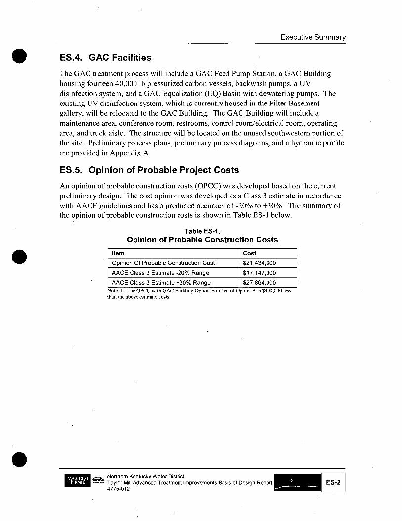
ES.5. Opinion of Probable Project Costs
An opinion of probable construction costs (OPCC) was developed based on the current preliminary design. The cost opinion was developed as a Class 3 estimate in accordance with AACE guidelines and has a predicted accuracy of -20% to +30%. The summary of the opinion of probable construction costs is shown in Table ES-I below.
Table ES-1. Opinion of Probable Construction Costs
Item Cost
Opinion Of Probable Construction Cose $21,434,000
AACE Class 3 Estimate -20% Range $17,147,000
AACE Class 3 Estimate +30% Range $27,864,000 Note: I. The opec wLth GAC Bulldmg Opt Lon B m lieu of OptLon A IS $400.000 less than the above estimate costs.
1IIIIIIII ~ Northern Kentucky Water District ... -...: Taylor Mill Advanced Treatment Improvements Basis of Design Report
4775-012 ES-2

•
•
•
1. Introduction
1.1. General
The Basis of Design document for the Taylor Mill Water Treatment Plant Advanced Treatment Improvements Project provides an overview of the process and facility modifications that are to be designed and constructed as part ofthis project. The Preliminary Design o/GAG Systems Report (by Malcolm Pimie, Inc. and GRW, Inc., dated March 2008) served to define the basic scope of work anticipated for the project.
The Stage 2 Disinfectant/Disinfection By-product (D/DBP) Rule will require utilities to transition from meeting system-wide running annual averages (RAAs) for TTHMs and HAAS to meeting locational running annual averages (LRAAs) at eaeh sampling 10,cation by 2012. The Stage 2 D/DBP Rule requires that the LRAA concentrations ofTTHMs and HAA5 remain at or below 80 and 60 ).tg/L, respectively. Based on testing completed as part of past projects, it was found that the Northern Kentucky Water District (NKWD, District) will not meet the regulations with the current treatment approach, therefore, granular activated carbon (GAC) treatment was selected.
The major areas of work include removal and replacement of the existing rapid mix, flocculation and sedimentation basins, installation of a new GAC treatment process including a GAC influent pump station, GAC building, equalization basin, and relocation of the existing UV disinfection system.
All project related improvements are located at the Taylor Mill Water Treatment Plant (TMTP), a 10 MGD conventional treatment facility, located in Kenton County. The plant receives its source water from the Licking River, a tributary of the Ohio River. Approximately 45% of the District's customers rely on the TMTP for their water supply, which is more than TMTP's rated capacity. The balance of the demand is met by blending water treated by the Fort Thomas Treatment Plant (FTTP).
1.2. Organization
The Basis of Design is organized into separate sections covering the various work disciplines as follows:
.. Section 2
• Section 3
• Section 4
~, --
Site/Civil
Architectural
Structural
Northern Kentucky Water District Taylor Mill Advanced Treatmenllmprovements Basis of Design Report 4775-012

•
•
•
Section 1 Introduction
• Section 5 Process Mechanical
• Section 6 HVAC
• Section 7 ' Plumbing
• Section 8 Electrical
• Section 9 Instrumentation and Control
• Section 10 Permitting
• Section 11 Suggested Sequence of Construction
• Section 12 Opinion of Probable Construction Costs
Sections 2 through 9 are further divided into numbered subsections as follows (where 'X' denotes the appropriate Section number):
Subsection Xl Introduction Subsection X.2 Design Approach Subsection X.3 Materials, Equipment and Systems Subsection X.4 References Subsection X.S Miscellaneous
1.3. Facilities
New site facilities will include the following:
• Open basin rapid mix chamber
• Flocculation basins (2)
• Sedimentation basins (2)
• GAC feed pump station
• GAC building
• GAC EQ basin
_ Q.. Northern Kentucky Water District --: Taylor Mill Advanced Treatment Improvements Basis of Design Report
4775-012 1-2
• 2. Site/Civil
•
•
2.1. Introduction
Site/Civil improvements, as shown in figure 2-1 of Appendix A, will be made to facilitate the new GAC process and the replaced preliminary treatment. Access will be required to allow additional tanker truck access for the loading and unloading of GAC. The proposed improvements may have an impact on the current stonnwater control of the facility. Approaches will be implemented to keep as much pervious area as possible and to keep the site facilities as far as practicable from the existing public neighbor that borders the western site boundary. Once the spatial layout of the buildings and the type of roofing systems for the buildings are finalized, the storm water control measures will be determined.
Site improvements include the following:
• Modifications to the Northwest service drive to incorporate access to the new GAC facility
• Modifications to the site grading required for the new facilities
• Stormwater control measures including retention basins, infiltration swales and rain gardens as required
• Inclusion of up to three parking spaces adjacent to the new GAC facility
• Incorporation of vehicle access to the GAC PS for removal maintenance activities associated with the GAC Supply Pumps
• Miscellaneous site piping including the following:
• Connection to the existing 36-inch plant discharge along the Northwest property line for backup GAC contactor backwash connection and plant water feed to the GAC building ,
• New GAC equalization basin overflow, and discharge connection
• New GAC Pump Station with supply line, discharge line and overflow
• New GAC contacted water line (from GAC facility to Clearwell, through north filter piping gallery)
• New gravity sewer connection (from GAC facility to existing 8" sanitary line)
• New 24-inch settled water pipe from new settled water effluent trough to the north side of the Filter Building
II Removal of the 8-inch backwash recycle pipe that is on the east side of the preliminary treatment facilities. This pipe is reported to no longer be used .
•. Q.., -- Northern Kentucky Water District
Taylor Mill Advanced Treatment Improvements Basis of Design Report 4775-012

•
•
•
Section 2 Site and Civil
• Possible relocationlreplacement of the 6-inch residuals pipe on the east side of the preliminary treatment facilities. This pipe may be disturbed during construction.
• Replace drive, curbs, and landscaping immediately south and west of the existing south sedimentation basin. These items will be removed during excavation for the new preliminary treatment facilities.
• Replace the stonn water inlet and a portion of the 12-inch stonn sewer located at the southwest comer of the existing south sedimentation basin. These items will be removed during excavation for the new preliminary treatment facilities.
• Relocate a segment of the 4-inch sewage force main near the southeast comer of the south Sedimentation Basin.
2.2. Design Approach
With the existing site configuration and topography, stonnwater control options are limited and costly. Therefore, "green" infrastructure approaches have been recommended for control. The goal of the stonnwater control approach is to maintain the same pre construction and post construction runoff characteristics. The proposed GAC building, Preliminary Treatment Building and GAC Feed Pump Station will have vegetative roofs to maintain pervious surface and mitigate the need for a stonnwater retention basin. Other "green" approaches include routing'downspouts for new facilities to rain gardens and surface runoff to infiltration swales.
The traffic impact of the new GAC facilities includes additional tanker truck traffic on a monthly basis for the loading and unloading of GAC from the GAC pressure vessels located in the GAC facility. Access will ~e provided for tankers to utilize the existing plant entrance along Grand Ave.
A landscaping plan will be developed. The plan will address the replacement of landscaping removed for construction purposes (around the south sedimentation basin) and new landscaping near the GAC Building.
Northern Kentucky Water District Taylor Mill Advanced Treatment Improvements Basis of Design Report 4775-012
2-2

•
•
•
2.3. Materials Table 2-1.
Materials of Construction
Description Material Location
New or Replaced Concrete GAC access drive, Pavement/parking GAC pump station
access drive
Retaining wall Segmental modular TBD concrete block
Sanitary sewer pipe SDR 35 TBD
Sanitary sewer Precast concrete TBD manholes
Settled water pipe Restrained joint DIP TBD
Residuals pump Restrained joint DIP TBD station discharge
GAC pump station Restrained joint DIP TBD influent
GAC pump station Restrained joint DIP TBD overflow
GAC contactor Restrained joint DIP TBD influent
EQ basin overflow Restrained joint DIP TBD
Stormwater drainage RCP Near preliminary pipe treatment facilities
Stormwater catch Precast concrete Near preliminary basins with cast iron grates treatment facilities
Security fencing Galvanized steel GAC building area
2.4. References
• Kentucky Basic Building Code
• Recommended Standards for Water Works \
• American National Standards Institute
• American Water Works Association
• Kentucky Transportation Cabinet
• Kentucky Division of Water
• Occupational Safety and Health Administration
• Sanitation District No.1 Rules and Regulations
Northern Kentucky Water District Taylor Mill Advanced Treatment Improvements Basis of Design Report 4775-012
Section 2 Site and Civil
•
•
•
2.5. Miscellaneous
Section 2 Site and Civil
The 36 inch supply line that runs South to North, located to the East of the new GAC Building, may need to be relocated as part of the project. This is still under investigation, but will be presented at a future progress meeting.
Q.., -- Northern Kentucky Water District Taylor Mill Advanced Treatment Improvements Basis of Design Report 4775-012
2-4

•
•
3. Architectural
3.1. Introduction
The existing Taylor Mill Treatment Plant campus has multiple buildings (4) beginning with the 1953 Plant building through the 2006 Backwash Treatment and UV Disinfection facilities. The 1953 building has a significantly higher level of architectural design and the subsequent buildings are fairly utilitarian. All the buildings utilize a similar terra cotta color brick veneer as the exterior finish material. Preliminary floor plans and elevations for each facility are included in Appendix A along with renderings of proposed Alternatives A and B for the GAC Building.
3.2. Design Approach
The most open and level area of the site available is located at the southwest portion of the site adjacent to Grand Avenue at the opposite end of the site from the 1953 original Plant building. The GAC Building was sited here due to its building area, the need for tractor truck access, and the fact that the rest of the open site area slopes significantly. The new Preliminary Treatment Building has been placed at the location of one of the existing Preliminary Treatment Basins being demolished and the GAC Feed Pump Station to the north or just behind the new Preliminary Treatment Building at the location of the other basin being demolished.
The overall plan is that the new GAC Building and the original 1953 Plant building would act as book ends by being more architecturally significant. The Preliminary Treatment Building and GAC Feed Pump Station architectural design would be similar to the other newer buildings.
Sustainable initiatives for all new buildings currently being considered are: Vegetative roof system (which reduces storm water run off while increasing storm water quality I reduces heat island effect of the roof), envelope design that includes an R-value higher than standard (increase energy conservation I optimization), reuse of existing basin footprints (site recycling), use of regional I recycled materials, and collection and reuse of roof water. Buildings utilizing vege~ati ve roof systems wi II incorporate a perimeter handrail system and the vegetative roof will be slightly sloped to provide an improved viewing angle. '
3.2;1. Preliminary Treatment Building
This building is sited at the current location of the south flocculation and sedimentation • basins. The building is approximately 84'x 67' and is 5,628 SF. It contains the new
~, -- Northern Kentucky Water District Taylor Mill Advanced Treatment Improvements Basis of Design Report 4775-012
3-1

•
•
•
Section 3 Architectural
flocculation / sedimentation basins. An electrical room is not shown but may be required. The effluent troughs shown are outside the building and make the entire structure approximately 95'x 72'.
3.2.2. GAC Building
Two options are proposed for this building. Each option includes the following spaces: truck ~isle, GAC vessel area, UV electric room, EQ basin, backwash! maintenance storage area, control room, electrical room, conference room, janitor, toilet, and entry lobby. The overall design of this building attempts to control the height of the building and overall scale by use of a low slope vegetative roofto minimize the impact on the adjacent residential neighborhood.
• Option A contains approximately 11,896 SF. The main volume of the building is the GAC contactor area / truck aisle. This option has two smaller volumes facing south with the equalization basin in between. One volume is office type program / dry areas and one volume is maintenance / wet areas.
• Option B contains approximately II ,458 SF. The main volume of the building is the' GAC vessel area / truck aisle (same as option A). This option has one smaller volume at the southeast of the building with the equalization basin to the southwest.
The options show different types of roofs on the smaller volumes. These roofs are interchangeable for either option.
In both options, there will be a formal entrance into a lobby with access to the administrative areas of the fa9ility. A secondary entrance is proposed adjacent to the parking areas, with carbon tanker truck access provided through an overhead coiling door. Control joints have been provided on the West wall of the facility to allow the installation of an overhead door for truck pull through.
As of January 21,2009 NKWD had chosen Option B.
3.2.3. GAC Feed Pump Station
This building is sited at the current location of the north flocculation and sedimentation basins. The building is approximately 1,323 SF and has two rooms. The pump room is the main volume and lower volume is an electrical room at the north of the building. The building will include an interior bridge crane. Access to the building is proposed by making a new double man door opening at the north wall of the existing connector to the Chemical Feed Building, adjacent to the existing pair of doors at the end of the alley, to the east of the Chemical Building.
Northern KentuCky Water District _ Taylor Mill Advanced Treatment Improvements Basis of Design Report 4775-012 '
3-2

• 3.3. Materials, Equipment and Systems
3.3.1. Interior Materials
Section 3 Architectural
Interior wall finishes being considered are painted CMU, ground faced CMU, and oversized clay masonry units for durability and wash down (As of January 30, 2009 NKWD had decide on ground faced CMU for both the GAC Building and the Preliminary Treatment Building). Exposed concrete plank will generally be the finished ceiling. The conference room control room area of the GAC building is proposed to have a suspended acoustical ceiling at 10' above finished floor. The conference room will utilize a drywall material for the walls
3.3.2. Exterior Materials
Exterior wall materials will generally be clay masonry veneer to match the existing buildings. Fenestration at the GAC building is proposed to be insulated translucent panels. Roofs are proposed to be vegetative roof systems utilizing vegetation that requires minimum water and maintenance.
3.4. References
The Kentucky Building Code (KBC) is the 2006 International Building Code (IBC) with amendments.
• PRELIMINARY BUILDING CODE ANALYSIS
•
• Height and floor area of the building:
• Preliminary Treatment Building: Height 25' +/-, Area 5628 SF +/-
• GAC Building: Height 31' +1-, Area 11,900 SF +/-
• GAC Feed Pump Station Building: Height 30' +/-. Area 1,323 SF +/-
• Occupancy Classification:
• Preliminary Treatment Building: F -1, Factory Moderate Hazard
• GAC Building: F-I, Factory Moderate Hazard
• GAC Feed Pump Station Building: F-l, Factory Moderate Hazard
• Construction Classification:
• Preliminary Treatment Building: IIIB
• GAC Building: lIIB
• GAC Feed Pump Station Building: IlIB
• Area Modifications: Height and Area for F- I buildings of IIIB construction is 2 stories with a building footprint of 12,000 SF. An area modification is not required.
_ • Q... . -- Northern Kentucky Water District Taylor Mill Advanced Treatment Improvements Basis of Design Report 4775·012

•
•
•
Section 3 Architectural
• Means of Egress: F-l occupancy load calculated for Industrial areas 100 SF per person and for Conference Rooms 15 SF per person. Occupancies over 49 persons require two means of egress. Maximum egress travel distance is:
• Preliminary Treatment Building: Two means of egress required / Maximum travel distance 200' .
• OAC Building: Two means of egress required / Maximum travel distance 200'.
• OAC Feed Pump Station Building: One means of egress required / Maximum travel distanee 75' (KBC 1019.2).
• Accessibility: The OAC conference room, control room, and toilet are accessible.
• Automatic Sprinkler Requirements: The threshold for F-l classified buildings is 12,000SF (KBC 903.2.3). An automatic sprinkler system is not required.
• A modified code review indicating the buildings occupancy classification, as F-2 Factory Industrial Low Hazard, is being submitted to Northern Kentucky Area Planning Commission.
• IfNKAPC concurs, this would increase the base allowable foot print to 18,000SF.
3.5. Miscellaneous
It is our understanding that the LEED system of checklists, UOBC registration, and commissioning is not a requirement for the project.
-~. -- Northern Kentucky Water District
Taylor Mill Advanced Treatment Improvements Basis of Design Report 4775-012

•
•
•
4. Structural
4.1. Introduction
Several new structures are planned as part of the project. This section describes the basis for structural design of these facilities. The geotechnical consultant's recommendations have not been received as ofthe date of this report.
4.2. Design Approach
Design shall be accomplished to provide' watertight tank structures, which remain in the elastic stress range to limit the potential for cracking. Non-water retaining structures shall also be designed conservatively in keeping with the essential nature of the facility. Loading conditions shall be based on the worst operating scenario to design for static conditions. Design water surface elevations shall be based on the maximum level possible, and in some instances, in excess of levels shown on the hydraulic profile. The hydraulic profile water elevations shall be used for seismic design.
4.3. Facilities
4.3.1. Preliminary Treatment Facilities
This structure consists of rapid mix, flocculation, and sedimentation basins covered by a building. The basins shall be cast-in-place concrete and the building will be masonry eMU load bearing walls with brick veneer. The roof will be precast hollow core slabs.
4.3.2. GAC Feed Pump Station
The pump station wet well and foundation will be cast-in-place concrete. The building above the pump'station will be masonry eMU load bearing walls with brick veneer. The roofs will be precast hollow core slabs.
4.3.3. GAC Building
The GAC Building will be masonry eMU load bearing walls with brick veneer. The roofs will be precast hollow core slabs.
4.3.4. Backwash Equalization Basin
This structure will be constructed of cast in place concrete.
4.3.5. Existing Tunnel
This is an existing structure and it will remain as it is except that the east end of the tunnel roof, which is severely deteriorated, will be replaced. The existing rapid mix will
Q... Northern Kentucky Water District _.... Taylor Mill Advanced Treatmenllmprovemenls Basis of Design Report
4775-012 4-1
•
•
•
Section 4 Structural
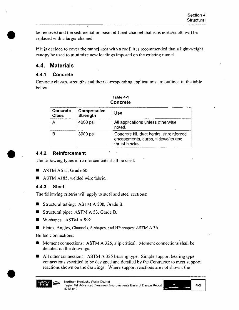
be removed and the sedimentation basin effluent channel that runs north/south will be replaced with a larger channel.
If it is decided to cover the tunnel area with a roof, it is recommend~d that a light-weight canopy be used to minimize new loadings imposed on the existing tunnel.
4.4. Materials
4.4.1. Concrete
Concrete classes, strengths and their corresponding applications are outlined in the table below.
A
B
Compressive Strength
4000 psi
3000 psi
4.4.2. Reinforcement
Table 4-1 Concrete
Use
All applications unless otherWise noted.
Concrete fill, duct banks, unreinforced encasements, curbs, sidewalks and thrust blocks.
The following types of reinforcements shall be used:
• ASTM A615, Grade 60
• ASTM A185, welded wire fabric.
4.4.3. Steel
The following criteria will apply to steel and steel sections:
• Structural tubing: ASTM A 500, Grade B.
• Structural pipe: ASTM A 53, Grade B.
• W-shapes: ASTM A 992.
• Plates, Angles, ChalU1els, S-shapes, and HP-shapes: ASTM A 36.
Bolted Connections:
• Moment connections: ASTM A 325, slip critical. Moment connections' shall be detailed on the drawings.
• All other connections: ASTM A 325 bearing type. Simple support bearing type connections specified to be designed and detailed by the Contractor to meet support reactions shown on the drawings. Where support reactions are not shown, the
~. _ .... Northern Kentucky Water District Taylor Mill Advanced Trealmenllmprovements Basis of Design Report 4775-012
4-2

• Section 4 Structural
connections shall be designed to carry half of the total unifonn load capacity tabulated in AISC tables for al10wable loads for laterally supported members.
4.4.4. Stainless Steel
The following criteria shall apply to stainless steel and stainless steel sections: .
• ASTM A 276 (bars & shapes) (annealed).
• ASTM A 4801 A 666 (plate).
• Type 316, (Type 304 for architectural uses) Fy = 30 ksi.
• Type 316L, (Type 304L for architectural uses) Fy 25 ksi (required where subject to welding)
• Bolted connections (114" to 5/8") ASTM A 593/A 594, Condition CW, match type of stainless steel connected (Fu = 100 ksi, Fy 65 ksi).
• Bolted connections (3/4" to I 112") ASTM A 593/A 594, Condition CW, match type of stainless steel connected (Fu 85 ksi, Fy = 45 ksi).
4.4.5. Aluminum
Aluminum sections shall be Alloy 6061 T6.
4.5. Design Criteria·
• . DEAD LOADS
•
The fo1lowing dead load criteria shall be used:
Table 4·2. Dead Loads
ITEM DEAD LOADS
Concrete 150 pct
Steel 490 pet
Aluminum: 169 pet
• CMU, normal weight, 8" wide 92 psf (grout solid)
I
65 psf (grouted @ 32" on center)
50 psf (ungrouted)
Northern Kentucky Water District Taylor Mill Advanced Treatment Improvements Basis of Design Report 4775-012
4-3

•
•
•
ITEM DEAD LOADS
CMU, normal weight, 12" wide 140 psf (grouted solid)
93 psf (grouted @ 32" on center)
69 psf (ungrouted)
Clay Masonry (8" wide) 86 psf (grouted solid)
Fiberglass 100 to 115 pet
Wood 40 pcf \
Soil 130 pcf
Gravel 145 pcf
LIVE LOADS ,
The following live load criteria shall be used in addition to concentrated loads:
Table 4·3. Live Loads
ITEM LIVE LOADS
Roof load, Basic LL 30 psf
Office floors 50 psf
Electrical/Mechanical rooms 150 pSf (in addition to equip loads)
Walkways, platforms, stairs 100 psf
Liquid loads 62.5 pcf
Shop Areas 200 pSf
Traffic loads Use AASHTO H-20 loading requirements for all vehicle access areas.
Forklift loads Use wheel loads based on manufacturer's data for the maximum forklift capacity designated for each specific location
Monorail loadings Vertical load = hoist system DL + (1.25 x hoist rated capacity)
Northern Kentucky Water District Taylor Mill Advanced Treatment Improvements Basis of Design Report 4775-012
Section 4 Structural
4·4

•
•
•
Section 4 Structural
WIND LOADS
Design will be in accordance with the requirements of the Kentucky Building Code.
Table 4-4. Wind Loads
ITEM WIND LOADS
Basic wind speed (3-second 90 mph
gust)
SNOW LOADS
Design will be in accordance with the requirements of the Kentucky Building Code.
Table 4-5. Snow Loads
ITEM SNOW LOADS
Ground snow load, Pg 1Spsf
SEISMIC LOADS
Design will be in accordance with the requirements of the Kentucky Building Code.
Table 4-6. Seismic Loads
ITEM SEISMIC LOADS
Seismic use group II
Spectral response coefficients SDS = 0.125, SD1 = 0.051
Site class, Pg B
Seismic Design Category B
Northern Kentucky Water District Taylor Mill Advanced Treatment Improvements Basis of Design Report 4775-012
4-5

•
•
SAFETY FACTORS
The following Factors of Safety will be used for stability calculations:
Table 4-7. Safety Factors
ITEM SAFETY FACTORS
Overturning 1.5
• Sliding I 1.5
Buoyancy 1.5 for groundwater at normal
mean elevation.
1.10 for groundwater at 100-year
flood elevation.
r
Section 4 Structural
Forces resisting buoyancy shall be a combination of structure dead load, weight of soil directly over footings (considering buoyant soil weight), and the tensile resistance of piles and/or tension anchors (based on allowable load values provided by the geotechnical report). Where there are superstructures above grade, the drawings shall clearly indicate at what level of completion dewatering can be stopped.
4.6. References
4.6.1. Building Code The design of this project will be governed by the following building code: • Kentucky Building Code.
4.6.2. Codes and Standards The following codes and standards shall be used in the structural design of this project:
• AASHTO. Standard Specification for Highway Bridges, Seventeenth Edition, 2002, American Association of State Highway & Transportation Officials, Washington, DC.
• ACI 318. Building Code Requirements for Structural Concrete, 2005, American Concrete Institute, Farmington Hills, MI.
• ACI350. Code Requirements for Environmental Engineering Concrete Structures, 2006, American Concrete Institute, Farmington Hills, MI..
• ACI 530/ ASCE 5ITMS 402 & ACI 530. II ASCE 6/TMS 602. Building Code Requirements for Masonry Structures, 2002; & Specification for Masonry Structures, 2002, American Concrete Institute, Detroit, MI;
-
,Q.. -- Northern Kentucky Water District Taylor Mill Advanced Treatment Improvements Basis of Design Report 4775-012
4-6 I

•
•
•
Section 4 Structural
• AISC/ ASD. Manual of Steel Construction Allowable Stress Design, Thirteenth Edition, American Institute of Steel Construction, Inc., Chicago, lL.
• PCl. PCI Design Handbook, Sixth Edition, 2004, Precast/Prestressed Concrete Institute, Chicago, IL.
4.7. Miscellaneous
4.7.1. Existing Conditions The existing flocculation and sedimentation basins will be demolished and replaced due to severe deterioration of the concrete which is about 50 years old. NKWD's decision to replace the basins was based on the findings and recommendations contained in a May 2006 study by Black & Veatch. The Black & Veatch study focused on the water holding walls and troughs that are above grade and exposed to freezing temperatures. A basin diagram in the report indicates that the exposed walls should be replaced but the tunnel is to remain. However, the report did not contain an explicit recommendation that the tunnel remain in place.
An evaluation of the tunnel was performed to verify the tunnel can remain in service. The evaluation included an inspection and concrete testing. It was concluded that the tunnel is in adequate condition to be remain in place. A memorandum summarizing the evaluation is included in Appendix B to this report.
4.7.2. Leadership in Energy and Environmental Design {LEE D) Goals The structural design will be in accordance with LEED goals outlined in the Architectural section of this report.
4.7.3. Geotechnical Information
The geotechnical field work has been completed, but the report and recommendations have not yet been received. We have assumed H-piles will be required for foundation support for new structures based on preliminary discussions with Geotechnical Engineer.
Q.., Northern Kentucky Water District -- Taylor Mill Advanced Treatment Improvements Basis of Design Report
4775-012

•
•
•
5. Process Mechanical
5.1. Introduction
Process Mechanical improvements will be made as part of the Taylor Mill Advanced Treatment Improvements project to connect the existing facilities to the replaced preliminary treatment process, the new GAC treatment process, and the relocated UV disinfection system. Preliminary process plans, preliminary process diagrams, and a hydraulic profile are provided in Appendix A.
The preliminary treatment process includes rapid mixing, flocculation, and sedimentation. The concrete in the existing rapid mix, flocculation, and sedimentation basins is severely deteriorated, requiring replacement of these process basins. Piping and trough modifications will be implemented to connect the raw water main to the new rapid mix and connect the new sedimentation process to the existing filtration process. The pumps in the'existing residuals pump station will also be replaced.
A 2006 evaluation of the concrete in the existing preliminary treatment basins included a limited evaluation of the tunnel that is located between the two flocculation basins . GR W inspected the tunnel in December 2008 and Thelen Associates perfoJ1!led coring and testing of concrete in the tunnel walls and roof. Based on the concrete testing results GRW concluded that the tunnel may remain in service perfonning its current function. A memorandum summarizing the tunnel evaluation is provided in Appendix B.
The GAC treatment process will include a GAC Feed Pump Station, a GAC Building housing fourteen 40,000 lb pressurized carbon vessels, backwash pumps, a UV disinfection system, and a GAC Equalization (EQ) Basin with dewatering pumps. The existing UV disinfection system, which is currently housed in the Filter Basement gallery, will be relocated to the GAC Building.
The GAC Feed Pump Station will be supplied from the current filter effluent header. Piping modifications will be made to connect to the existing header and a line will be routed to the southeast corner of the GAC Feed Pump Stati~m wetwell. A bypass connection will also be made in the North Piping Gallery of the Filter Building Basement to allow bypassing of both the GAC facilities and UV disinfection facilities .
_ c::;;&., -- Northern Kentucky Water District Taylor Mill Advanced Treatment Improvements Basis of Design Report 4775·012

••
•
•
Section 5 Process Mechanical
The GAC Feed Pump Station discharge header will be routed from the northwest corner of the pump station to the northeast corner of the GAC Building to supply the fourteen GAC vessels. After the GAC vessels, a GAC contacted water header will convey flow through UV disinfection to the existing cIearwell. The header will also exit the northeast corner of the GAC Building. The GAC Building will also be equipped with a GAC bypass located on the GAC influent line as wel1 as a UV emergency bypass.
Backwash waste and vessel-to-waste water will be conve'yed to the GAC Equalization Basin. A visual observation well and air gap will be provided on the waste header for inspection of the wastc. Basin contents will be recycled to the head of the plant.
5.2. Design Approach
5.2.1. General
The existing treatment plant has a nominal design capacity of 10 MGD. NKWD established a hydraulic design capacity of 12 MGD for the new rapid mix, flocculation, sedimentation, and GAC treatment facilities. The rated plant capacity will remain 10 mgd for planning purposes.
5.2.2. Preliminary Treatment Facilities
5.2.2.1. Rapid Mix
A new two-stage rapid mix will be provided to disperse pre-treatment chemicals into the process stream. The second stage will provide a redundant mixer and allow staged feeding of chemicals, if desired. The existing rapid mix basin will be removed. The components of this treatment process are presented in Table 5-1.
Table 5-1. Rapid Mix Design
Description Design
Number of Basins ?
Mixer Type Vertical Turbine
Basis of Design Ughtnin
Number of Impellers per Shaft 1
G Value, sec ., at 32 degrees 1000 (KDOW; no standard, Ten States Standards: minimum 750) Fahrenheit
Detention time, seconds Maximum Flow (12 MGD), Two 16 (KDOW: < 60, TSS <: 30) This Mixers in Service is in compliance with KDOW
draft guidelines which have not yet been adopted
Maximum Flow (12 MGD). One 8 Mixer in Service
Minimum flow (4.5 MGD), Two 142 Mixers in Service
~ Northern Kentucky Water District -...: Taylor Mill Advanced Treatment Improvements Basis of Design Report
4775-012

•
•
•
Description
Basin Dimensions
Chemical Feed Points
Drives
Controls
Design Concepts
5.2.2.2. Flocculation
Design
Minimum flow (4.5 MGD). One Mixer in Service
Width, feet
Length. feet
Sidewater Depth, feet
Freeboard, feet
Sodium Hypochlorite
Caustic Soda
Ferric Sulfate
Hybrid Coagulant
Copper Sulfate/PAC
Motor Horsepower (Per Mixer)
Speed Control
VFDs located in the tunnel
21
4.75
4.75
6.5
2.5 +/-
Section 5 Process Mechanical
~~ ... ~
Existing tap
Existing tap New tap in pipe before new RM Pipe to second stage RM
Existing tap New tap in pipe before new RM Pipe to second stage RM
Existing tap New tap in pipe before new RM Pipe to second stage RM
Existing tap
10
Variable Frequency Drives
Start/stop control at VFDs and mixers
Start/stop control in SCADA
Speed control at VFDs and through SCADA
Drive status and run time monitored in SCADA ---Semi-automatic speed control based on setpoint G-value and water temperature entered in SCADA by operators.
Top of basin to be open grating with steel support structure for mixer
i Fiberglass panels will be used on all exterior troughs to guard against freezing conditions. Interior troughs will utilze aluminum grating. Concrete will be utilized where walkways cross troughs (mainly near doorway access.
Provide drain valve(s) and piping for draining to residuals treatment facilities
A new three·stage tapered flocculation process will be provided. Th~ basis of design considers providing all new flocculation equipment; however, recommendations have been requested from Lightnin regarding the feasibility of reusing the eight existing 1.0 horsepower mixers in the second and third flocculation stages. The components of this treatment process are shown in Table 5·2.
Q.. Northern Kentucky Water District .-...: Taylor Mill Advanced Treatment Improvements Basis of Design Report
4775-012
I I

•
•
•
Description
Influent Flume
Influent Flow Splitting Gates
Effluent Gates
Number of Flocculation Basins
Mixer Type
Basis of Design
Number of Impellers per Shaft
Mixing G Values, seconds ·1
Detention Time, minutes
Mixer Peripheral Speed, fps
Overall Dimensions of Each Basin
Drives
I Controls
Design Concepts
Baffle Walls
Table 5-2. Flocculation Design
Design
Section 5 Process Mechanical
Provide valve and piping for draining to residuals treatment facilities
• Provide grating on top of channel for access
Freeboard: 1,5 feet
One influent gate per basin for flow adjustment and basin isolation
Two gates per basin for basin isolation
4
Vertical Turbine
Ughtnin
1
Stage 1 80
I Stage 2 50
Stage 3 35
Maximum flow (12 MGD) 34 (Exisiting: 30, KDOW: 40-60, Ten States Standards: 30)
Minimum Flow (4.5 MGD) 90 (all basins in service)
Stage 1 8.0
Stages 2 and 3 7.6
Width, feet 15
Length, feet 14
Average Sidewater Depth, feet 15
Freeboard, feet 1.25 ~
Stage 1 Horsepower 1.5
Stage 2 Horsepower 1.0
Stage 3 Horsepower 1.0
Speed Control Variable Frequency Drives
VFDs located in the tunnel
Start/stop control at VFDs and mixers
Start/stop control in SCADA
Speed control at VFDs and through SCADA
Drive status and run time monitored in SCADA
Semi - automatic speed control based on setpoint G-value and water temperature entered in SCADA by operators
Provide individual basin drains, which will match the elevation of the existing valves, for draining clear water to storm sewer.
Also provide individual basin drains in, bottom for draining res; residuals treatment facilities.
Hard pipe drains to stonm sewer or residuals sewer as appropriate
Concrete walls with circular ports will be utilized
Q.. Northern Kentucky Water District _ ..... Taylor Mill Advanced Treatment Improvements Basis of DeSign Report
4775-012 5-4

•
e,
•
5.2.2.3. Sedimentation
Section 5 Process Mechanical
A new plate settler sedimentation process will also be provided. The concrete in the existing residuals pump station, which was constructed in 1989, is in good condition and it is recommended that only the pumps, valves, and controls be replaced. The components of this sedimentation treatment process are presented in Table 5-3.
Table 5-3. Sedimentation Design
Description Design
I Number of Sedimentation Basins 2
Flow Per Basin Design: 6 MGD
! Maximum hydraulic throughput capacity per basin: 12 MGD (settling treatment objectives most likely will not be met at this max condition)
Basin Dimensions, Feet (for Width 30.5 sedimentation basins with plate Length 38.0 settlers)
Average Sidewater Depth 18.0 , Excluding Cross Collection Trough and Residuals Hopper
Maximum Water Depth, Including 21.25 Hopper
Freeboard 1.25
Volume, Excluding Cross Per Basin 156,000 Collector Troughs and Residuals Both Basins 312,000 Hoppers. Gallons
Detention Time. Minutes Both Basins in Service. 12 MGD 37
Plates (based on MRI plates with I Rows per Basin 5 effluent troughs on the side) Plate Cartridges per Row 1
Total Plates per Basin 594
Total Plates 188
Plate Width, feet 4,5
Plate Length, feet 10
Angle of Inclination. degrees 55
Effective Surface Area, % 80
Projected Surface Area per Plate, 20.65 sf
Effective Surface Area per Plate, 25.81 sf (At 80% Efficiency)
Effective Surface Area per Basin, 12,256 sf
Total Effective Surface Area. sf 24,512
Plate Surface Overflow Rate. 4.5 MGD With 2 Basins in 0.13 (KDOW s 0:5 GPM/SF) GPM/SF Service
12 MGD With 2 Basins in Service 0.34 (KDOW s 0.5 GPM/SF)
~ Northern Kentucky Water District _ -...: Taylor Mill Advanced Treatment Improvements Basis of Design Report 5-5
4775-012 . _
•

•
•
•
Description
Sedimentation Design Concepts
Residuals Collection I
Residuals Collection Drives
Residuals Collection Controls
Residuals Design Concepts
Residuals Blowdown
Residuals Blowdown Controls
Design
Section 5 Process Mechanical
Basins designed to meet treatment objectives at a maximum flow rate of 6 mgd per basin
Provide emergency overflow weir in effluent trough
Type g~ain and Flight with Cross ollectors .
Vendors EnvirexlSiemens, E&I
Flight Material Fiberglass
Chain Material Plastic
Retum Rail Material Fiberglass, CPVC, and Polypropylene
Sprocket Material Plastic
Number of Collectors per Basin 2
Number of Cross Collectors per 1 Basin
Bottom Slope, inches 6
Cross Collector Bottom Slope, 6 inches
Number of Drive Units Per Basin 2
Horsepower Per Unit 0.5
Speed Control Constant speed
Start/stop control at sedimentation basins and at MCC located in the tunnel
Start/stop control in SCADA
Drives operate in auto mode controlled by adjustable timers i
Interlock drives with corresponding basin blowdown valves so collection mechanisms operate when blowdown valves are open
Drive status and run time monitored in SCADA
High torque warning and torque overload alarm in SCADA
Visual torque overload alarm in the Preliminary Treatment Building
Provide individual basin drains 2 feet above floors for draining clear water to storm sewer
Drain lowest 2 feet of water and residuals through residuals drawoff pipes to residual processing facilities
Hard pipe drains to storm sewer or residuals sewer as appropriate
Gravity flow through one motor operated valve per basin
Residuals Flow Rate, gpm j TBD
Provide automatic control of motor operated varves in SCADA with adjustable blowdown interval and duration (Only one valve may be opened at a time)
Provide local manual control on the valves
Provide remote manual control in SCADA
Valve status monitored in SCADA
~ Northern Kentucky Water District . -...: Taylor Mill Advanced Trealmenllmprovements Basis of Design Report
4775-012

•
•
•
Section 5 Process Mechanical
Description Design
Residuals Pump Station Number of Existing Pumps 2
Reported Capacity per Pump, 400 gpm
Reported Existing Pump 7.5 Horsepower
Existing Pump Discharge Size, 4 inches
Number of Replacement Pumps 2
Capacity per Pump, gpm TBD (estimated 400 - 500)
New Pump Horsepower TBD (estimated 7.5 - 10)
New Pump Discharge Size, 4 inches
Residuals Pump Station Controls Replace existing float switches with new continuous level monitoring device.
Ability to change the pump level setpoints in SCADA
High level alarm (will close valve) and low (will stop pump) level alarm inSCADA
Visual local alarm at the pump station
Water level monitored in SCADA
Motor temperature and seal leakage monitored in SCADA
Pump status and run time monitored in SCADA
5.2.3. GAC Treatment Facilities
The GAC treatment facilities consist of a GAC Feed Pump Station, a GAC Building, and a GAC Equalization Basin. lnfonnation on each is presented in the following sections.
5.2.3.1. GAC Feed Pump Station
The GAC Feed Pump Station will receive water by gravity flow from the existing fi1ters. The wetwel1 will be designed utilizing the Hydraulic Institute (HI) recommendations for "sump design" with multiple pump installations. The wet well will be designed to meet the minimum required water elevation,_ provide a two foot control band range, and allow one and a half foot freeboard prior to the overflow elevation. Table 5-4 summarizes the wetwell design parameters, as recommended by pump manufactures and the HI.
Table 5-4. GAC Feed Pump Station Wetwell Design
Description Design
Total Wetwell Volume, gallons 37,700 +/-
Wetwell Length, feet 35 +/-
Wetwell Width, feet 18 feet +/-
Wetwell Operating Depth, feet 8 feet +/-
Volume of 2 Foot Control Band, gallons 9,400
c;;t.. Northern Kentucky Water District ----- Taylor Mill Advanced Treatment Improvements Basis of Design Report
4775-012 5-7

•
•
•
Section 5 Process Mechanical
A wetwell overflow will be provided and routed to a drainage swale to the north of the pump station. Wetwell overflows are expected to be used on an emergency basis and therefore, no permanent dechlorination facilities will be provided. NKWD will draft an emergency SOP to deal with emergency events.
The GAC Feed Pump Station will utilize three vertical turbine pumps, two service pumps and one standby, complete with variable frequency drives (VFDs). The firm capacity of the station will be 12 MOD with ~wo pumps operating at full speed. Table 5-5 summarizes the OAC feed pump design criteria.
Table 5-5. GAC Feed Pump Design
Description Design
Pump Type Vertical turbine
Minimum Flow One Pump @ 1,360 RPM 3,125 GPM @ 66 feet +/~
Duty Point One Pump @ 1,770 RPM 4,166 GPM @ 70 feet +/-I
Duty Point Two Pumps Operating in 8,333 GPM @ 81 feet +/-Parallel @ 1,770 RPM
Rated Speed, RPM 1,770
I Motor Horse Power, hp 125
• Pump Diameter, in 16
Pump Discharge, in 14
The discharge of each pump will be equipped with an air/vacuum release valve, check valve, and a butterfly valve for isolation purposes. The pumps will tie into a discharge header which will be routed around the pump room and exit the building below grade at the northwest comer of the room. The header will be equipped with a venturi meter and differential pressure transmitter for monitoring flow rate to the OAC facility. The header will also be equipped with a surge relief valve to protect the OAC vessels. The relief valve will discharge directly to the wetwell.
The level in the wetwell will be monitored by an ultrasonic level sensor. As the level in the wetwell raises or falls, the sensor will communicate with the PLC, which will control the VFDs, to match the speed being pumped out of the wetwell with the flow coming in from the filters by increasing or decreasing the flow of the pump(s). The two foot control band prO\;,ides the VFDs with time to match the incoming flow from the filters.
A separate electrical room will be provided adjacentto the pump room on the north side of the building. The electrical room will house the VFDs and ancillary electrical equipment and will be air conditioned, while the pump building will be ventilated only. An electric bridge crane will be provided in the pump building for removal and maintenance of the pumps, motors and valves. The height of the pump room will be
__ Q.. Northern Kentucky Water District -....: Taylor Mill Advanced Treatment Improvements BaSis of Design,Report
4775-012 5·8

•
•
Section 5 Process Mechanical
sized so that the pump column pipe can be lifted'from the wetwell by the bridge crane and uncoupled at five foot intervals.
The pump building and electrical room will have exterior double doors for removal of equipment. Since the GAC Feed Pump Station is located behind the existing tunnel, an addit,ional double door will be installed on the north side of the tunnel (double doors already exist on the south side of the tunnel). The double doors will be sized to allow access by a small forklift. The forklift and the electric bridge crane will be utilized to remove the pumps and motors and convey them to the south side of the tunnel where they can be loaded on a truck should off site maintenance be required.
5.2.3.2. GAC Building
The GAC Building is located on the west side of the plant property, along Grand Avenue. The north side of this location is bordered by steep topography, so the building layout is confined to the southern area of the open space. The open space is also bordered by an existing private residence to the west and an existing 36-inch water main to the east.
The GAC Building will house fourteen GAC pressure vessels, the relocated UV I
disinfection system, backwash pumps, compressed air system, plant water system, miscellaneous valves and instruments.
Several process layouts were discussed during progress meetings and the stakeholders selected a layout where all GAC vessels are aligned in an east west arrangement along the northern portion of the building, adjacent to the truck aisle. The layout confines all process areas to this northern portion of the building.
The southern portion of the building will house the administrative areas, including a lobby, control room, conference room, restroom, and janitor closet. The GAC Equalization (EQ) Basin will be located adjacent to the truck aisle on the south side of the facility as well.
This layout allows for a tiered appearance from the road. The selected arrangement . allows for the optimum piping layout and for hydraulic symmetry. Due to the size
requirements of the building, the distance to the neighbor's property line is approximately 30-feet. NKWD may want to consider purchasing the neighbor's property to allow for an increased distance between the residents and the GAC Building.
GAC PROCESS
Carbon pressurized vessels versus basin-style contactors were investigated as part of the Preliminary Design ofGAC Systems Report (by Malcolm Pirnie, Inc. and GRW, Inc., dated March 2008). The pressurized vessels wer~ selected due to the cost benefit, ease of carbon transfers, and the minimal excavation required in comparison to the basin-style
• _co_n_t_a_ct_o_r_s, ________________________________________________________ ___
c:::;;:;t.. Northern Kentucky Water District -...: Taylor Mill Advanced Treatment Improvements Basis of Design Report
4775-012

•
•
•
Section 5 Process Mechanical
During the information request phase, both 20,000 lb and 40,000 lb vessels were recommended by the vessel manufacturers. All vendors can provide both 20,000 lb and 40,000 Ib vessels. The use of 40,000 Ib pressure vessels reduces the number of vessels from 28 (20,000 lb vessels) to approximately 14 (40,000 Ib vessels), which ultimately simplifies the treatment system by reducing the number of valves and instruments required. Additionally, fourteen 40,000 lb vessels will occupy approximately 2,500 sf less than the 28-20,000 vessels. Furthermore, the 40,000 lb vessel arrangement also allows for the OAC EQ Basin to be located adjacent to the OAC Building, rather than across the plant entrance, adjacent to the Backwash Treatment Facility, which would require sub-grade construction and additional piping.
The disadvantages of the 40,000 lb vessel arrangement are that it requires multiple carbon loads to complete carbon transfers, requires a taller building, and there are limited installations (installed in two locations by Calgon). Weighing the advantages and disadvantages, the stakeholders selected 40,000 Ib vessels as the basis of design. It was considered that the site constraints and reduction of maintenance items outweighed the listed disadvantages.
The required number of vessels, fourteen, was determined based on a 20-minute empty bed contact time (EBCT), a plant design flow rate of 10 MOD, and the 40,000 Ib vessel capacity. The 20-minute EBCT was determined as part of the Preliminmy Design of GAC Systems Report (by Malcolm Pirnie, Inc. and ORW, Inc., dated March 2008). During carbon change-outs with 13 vessels running and a plant flow of 10 MOD, the vessels will have a 19-minute EBCT, which is slightly less than the target of 20-minutes. Since carbon change-outs for a single vessel can be aehieved in two days, and the EBCT is conservative, it was deeided that this was an acceptable level of treatment.
Based on vendor recommendations, the minimum surface loading rate is 2 gpm/sf and the maximum surface loading rate is 7 gpm/sf. Table 5-6 summarizes the number of vessels that can be operating to meet the EBCT and surface loading rate criteria.
Table 5-6. No. GAC Vessels Operating Versus Various Flow Conditions
No. Vessels Operating Flow Condition to Meet EBCT and
(MGD) Surface loading Rate Criteria
4.5 7-14
6 9-14
10 14
12 14 (EBCT -17 minutes)
c;;;t... Northern Kentucky Water District -- Taylor Mill Advanced Treatment Improvements Basis of Design Report
4775·012

•
•
•
Section 5 Process Mechanical
The fourteen vessels are configured in a seven, dual vessel system arrangement where each pair of vessels share a common 4-tier manifold. The manifold contains the GAC backwash waste, GAC influent, GAC effluent, and GAC backwash supply lines. Each pressurized vessel is provided with man ways, bed sampling ports, and carbon fill and drain lines. A rupture disk is also provided to keep the vessel from over pressurizing. The GAC vessels and equipment will be manufactured by ~algon Carbon Corporation (Calgon), Siemens Water Technologies (Siemens), or Norit-Americas (Norit).
A positive head loop is provided on the GAC contacted water header to ensure full vessel flow. A GAC bypass is located on the GAC influent line to bypass GAC treatment, but still route flow through UV disinfection.
VESSEL UNDERDRAINS
There are two types of underdrains that are available for the carbon pressurized vessels; false bottom type and external header type. The false bottom underdrain consists of approximately 80 to 120 strainers which are mounted on an internal cone false bottom. This type of underdrain increases the vessel structural requirements, requires confined space entry for maintenance, and may require more maintenance due to the hydraulic forces stretching the gasket materials. The false bottom underdrain provides more locations for failure of the internal coating and lS more prone to corrosion, but has the benefit of better flow distribution.
The external header underdrain consists of 8 strainers arranged on an external header located beneath the pressurized vessel. This underdrain type does not require vessel entry for maintenance and allows for a more consistent vessel lining as there are a limited number of welds. Current vessel owners confirmed that the external header underdrains require less maintenance than the false bottom type underdrains. Based on the above comparison, the external header underdrain was selected for the design.
VESSEL VALVING
As noted previously, the vessels will be configured in a seven pair vessel system arrangement. Each system will share a common 4-tier manifold. Each vessel will have dedicated valving located on the common manifold so that each vessel can process flow and perform backwashes separately. Two vessels will not perform backwashes simultaneously. The GAC backwash waste, GAC backwash supply, and GAC influent manifold valves will all be open/close automated valves. The effluent valves will be modulating valves controlled by a flow meter on the influent line to ensure that each vessel processes the same flow rate regardless of carbon saturation. The carbon fill and drain valves will be manually operated, as is the standard with pressurized vessels. Two vessel systems will share a common header to reduce the amount of piping required to convey flow to and from the main header, located along the north wall. The plant air and plant water lines are discussed in Sections 5.2.5.5 and 5.2.5.6. The piping sizes and
~ Northern Kentucky Water District -....: Taylor Mill Advanced Treatment Improvements Basis of Design Report
4775-012

•
•
•
Section 5 Process Mechanical
associated valve sizes required for the pressurized vessels are summarized in Table 5-7 below.
Table 5·7. GAC Pipe Sizes
Flow Description Pipe Description Pipe Diameter (in)
Main Header 24
Common Header 10 GAC Vessel (4 Vessels)
Influent Common Header 8 (2 Vessels)
I
Manifold 8 (1 Vessel)
Main Header 10
Common Header 10 GAC Vessel I
(4 Vessels) Backwash Supply Common Header 8 (2 Vessels)
Manifold 8 (1 yessel)
Main Header 10
Common Header 10
GAC Vessel (4 Vessels)
Backwash Waste i Common Header
(2 Vessels) 8
Manifold 8 (1 Vessel)
Main Header 24
Common Header 10 GAC Vessel (4 Vessels)
Effluent Common Header 8 (2 Vessels)
I Manifold
8 (1 Vessel)
GAC Vessel Carbon Fill 4
GAC Vessel Carbon Drain 4
GAC Vessel Plant Air 4
GAC Vessel Plant Water 4
~ Northern ~entucky Water District -...: Taylor Mill Advanced Treatment Improvements Basis of Design Report
4775-012
I
5-12

•
•
•
VESSEL FLOW CONTROL
Section 5 Process Mechanical
The rate of flow through each GAC vessel will be controlled to provide an equal flow rate to all vessels in service. Flow to the vessel will be monitored with a meter on the influent line to each vessel and the rate will be controlled by adjusting the effluent valve. The SCADA system will be programmed for flow control of the individual vessels based on a rate set with the discharge flow from the GAC Feed- Pump Station and the number of vessels in service.
ACCESSORIES
One GAC vessel will include a view port at the top ofthe vessel, near the GAC water interface. The view port will be made out of pyrex® glass and will not reduce the pressure rating of the GAC vesseL Additional access will be constructed at this vessel to allow two people to climb to the view port.
GAC BACKWASH
There are two modes of operation for vessel backwash, first, when the GAC is initially loaded into the vessel, and second, to "fluff' the media if needed to relieve some of the media compaction. The backwash flow rate requirements when GAC is initially loaded into the vessels are related to fine particle removal'. The fluidization required for fine removal varies with water temperature and GAC particle characteristics. Since 12 x 40 mesh GAC is the basis of design, Calgon recommended a backwash rate of 850 gpm for fine removal based on a 55 degree Fahrenheit water temperature. Based on backwash supply curves provided by Calgon and Nont, a range of 750 - 1500 gpm may be required based on a temperature range of 32 - 90 degrees and differences in carbon characteristics. The rate of flow to "fluff' the media is more arbitrary, as the duration of backwash is more critical. A "fluff' should not redistribute the carbon bed and requires five minutes or less of backwash flow. Calgon recommended that this rate be established during startup.
Two backwash alternatives were investigated as part of preliminary engineering and are as follows:
I. Backwashing with dedicated backwash pumps located in the GAC Feed Pump Station.
2. Backwashing by utilizing in-line vertical centrifugal booster pumps located on the effluent header prior to the positive head loop with a backup connection to the 36-inch high service main from the TMTP.
Alternative I has dedicated backwash pumps located in the GAC Feed Pump Station. Disadvantages of Alternative 1 include control issues that would arise during backwash when the rate of flow to the GAC process would be reduced by the flow required for backwash, the increase in wetwel1 size for backwash requirements, and the increase in GAC Feed Pump Station size to house the additional pumps.
~ Northern Kentucky Water District .M _...: Taylor Mill Advanced Treatment Improvements Basis of Design Report 4775-012

•
•
•
Section 5 Process Mechanical
Alternative 2 utilizes in-line booster pumps located in the GAC Building. By taking suction from the GAC contacted water line, the pumps require less horsepower to achieve the pumping requirements than backwash pumps taking suction from the GAC Feed Pump Station wetwell as proposed in Alternative 1. Furthermore, less piping is required for Alternative 2. A disadvantage of Alternative 2 is that it requires a backup connection to the 36-inch TMTP discharge line to allow backwashing during startup and low flow conditions. Alternative 2 was selected due to the simplicity in operation, the redundancy provided and the cost advantage, estimated in the order of $80,000.
The basis of design for Alternative 2 is to provide two in-line booster pumps one service, one standby. The backwash flow rate will be controlled by a modulating flow control valve on the backwash supply discharge line. This valve will communicate with the PLC via a 4-20 mA signal. The flow meter will also communicate with the PLC. A control loop will be set up for flow control. The valve will have local controls on the actuator as well as remote controls at the local panel. Table 5-8 summarizes the GAC backwash supply pump criteria.
Table 5·8. GAC Backwash Supply Pump Design
Description Design I
Pump Type In-line vertical centrifugal
Backwash Range, gpm 750-1,500 !
Quantity 2 pumps; one service, one standby
Rated Speed, RPM 1,750
Power. hp 15
: Pump Diameter, in 6
i Pump Discharge. in 6
The backup backwash supply will be provided with a connection to the 36-inch TMTP discharge line. Dual pressure reducing valves in series will reduce pressure from approximately 210 psig to 100 psig, then 100 psig to 30 psig. This supply will have an independent flow control valve and venturi flow meter.
UV DISINFECTION
The two existing UV systems will be relocated to the GAC Building. The UV reactors will be located post-GAC and prior to the positive head loop. The existing systems 'are designed to treat 89% UVT water with a Reduction Equivalent Dose (RED) of 40 mJ/cm2
•
By relocating the UV disinfection system post-GAC, a UV,. of approximately 95% is anticipated. The UV electrical and control panels will also be relocated and housed in a small electrical room near the UV reactors, while the UPS will be relocated to the main electrical room in the GAC Building. An emergency UV bypass will be located in the GAC Building. A GAC and UV bypass will be located in the existing Filter Basement
Q.. Northern Kentucky Water District _ -...: Taylor Mill Advanced Treatment Improvements Basis of DeSign Report 5-14
4775-012 _
•
•
•
Section 5 Process Mechanical
North pipe gallery. Documentation showing the options evaluated, in regards to the relocation of theUV reactors is attached as Appendix C.
PLANT WATER
Plant water will be supplied by the backwash connection to the 36-inch TMTP Plant Discharge line to the GAC Building. This connection will split to provide water for backwashing as well as for plant water use. There will be a backflow preventer located on both lines. The plant water line will have one pressure reducing valve to regulate the pressure from approximately 210 psig to 70 psig and will be sized to provide 100 200 gpm. This system will supply water for the various water requirements of the GAC treatment process as foHows:
III Carbon spray wash during spent carbon transfer (approximately 500 gallons at 100-200 gpm for 5 minutes)
III Pressurized vessel preparation for fresh carbon transfer (approximately 3,000 gallons at 100 200 gpm)
III Carbon truck preparation for fresh carbon transfer (approximately 5,000 gal10ns per 20,000 dry carbon)
PLANT AIR
Plant air will be supplied by a dedicated 30 hp rotary screw air compressor sized for 125 scfrn regulated down to 30 psig. The air compressor will be equipped with a desiccant . . . .
dryer and three air filters (2 pre-dryer, 1 post-dryer) and a 120-gallon receiver. The 4-'inch air lines will be hard piped to each vessel for use during the carbon transfers. One to three tank air supply connections will be provided. The feed line will have a regulator set to 15psi. This system will supply air for the various air requirements of the GAC treatment process as follows:
III Vessel preparation for spent carbon transfer (100 scfrn at 30 psig minimum)
II Spent carbon truck drain procedure (100 scfrn at 15 psig maximum)
II1II Truck preparation for fresh carbon transfer (100 scfrn at 15 psig maximum)
5.2.3.3. GAC Equalization Basin
The GAC treatment process requires an equalization basin to store flows from backwash waste events, vessel-to-waste events, carbon tanker truek drain events, and general wash down events of the GAC Building. The equalization basin was sized to hold 45,000 gallons and designed with a sump to facilitate c1eanout. This equalization size is based on the following:
III Drain water from two spent carbon truck loads
III One vessel backwash event (30 minutes at maximum backwash rate of 1,500 gpm)
~ Northern Kentucky Water District -....: Taylor Mill Advanced Treatment Improvements Basis of Design Report
4775·012 5-15

•
•
• '
III One vessel-to-waste event (60 minutes)
II Equalization dewatering rate of 10% of 4.5 MGD (~313 gpm)
• 10% safety factor
Section 5 Process Mechanical
Backwash waste or vessel-to-waste water will flow from the vessels through the backwash waste line located along the north and west walls. There will be an air gap located just upstream of the GAC EQ Basin to visually inspect the turbidity of the water if needed. This visual inspection will aid operators to ensure that large amounts of carbon are not exiting the top of the vessel and to verify when the backwash event is over (carbon fines are not largely visible). The GAC EQ Basin will be equipped with two 300 gpm submersible EQ dewatering pumps. The GAC EQ Basin effluent will be recycled to the head of the plant at a constant rate of300 gpm by tying into the current Filter-toWaste Return. This connection is shown on the Site Plan in Appendix A. The GAC EQ dewatering flow will take precedence over the filter-to-waste return flow and will be controlled automatically through SCADA. Details of operation will be finalized as the design develops.
The GAC EQ Basin will also be equipped with an overflow line that will connect to the filter-to-waste overflow line through the dechlorination station to avoid permit violations. An ultrasonic level transmitter will be provided for level status. Table 5-9 summarizes the GAC EQ dewatering pump criteria,
Table 5-9. GAC EQ Dewatering Pump Design
, Description Design
Pump Type Submersible
Duty Point 300 gpm @ 73 ft +/-
Discharge, in 8
5.3. Materials, Equipment, and Systems
5.3.1. Materials of Construction
The materials of construction associated with the preliminary and GAC treatment processes are summarized in below in Table 5-10 .
_ ~ Northern Kentucky Water District -- Taylor Mill Advanced Treatmenllmprovemenls Basis of Design Report
4775-012
6 -
-,...---- ... '~ 5-16

•
•
•
Table 5-10.
Section 5 Process Mechanical
Preliminary and GAC Treatment Processes Materials of Construction
Description Material Location
Flanged Pipe Ductile Iron. Inside all buildings
Restrained Joint Pipe Ductile Iron Buried and yard piping
Solvent Welded Pipe PVC Drain piping
Grating Aluminum Rapid Mix, Troughs
Gates Aluminum Preliminary Treatment
Handrail & Kick Plates Aluminum Walkways, Basins
Mixing Baffles Concrete Rapid Mix Basins
5.3.2. Equipment
The equipment associated with the Preliminary Treatment and GAC process facilities are summarized below in Table 5-11.
Table 5-11. Preliminary and GAC Treatment Processes Equipment
Description Type Quantity Design Conditions
Preliminary Treatment - Rapid Mix
I Mixer Turbine 2 G:= 1,000 Sec-1
I Drain Valve Plug 1 4-inch
Preliminary Treatment - Flocculation
Influent Gates i Rising Gate 4 Manual
Flocculators Turbine 12 I VFD controlled
Drain Valves for Clear Butterfly Valve 4 Manual,8-inch Water
Drain Valves for I Mud Valve 4 Manual, 8-inch Residuals
Baffles TBD 8 NSF Approved
Preliminary Treatment - Sedimentation
Influent Gates Rising Gate 8 Manual
! 5 Plate Cartridges Per SS Plates and troughs,
Plate Settlers Lamella Basin
55 degree angle of incline
i
I
I :
Residuals Collection Chain and Flight 2
One main collector per I basin, one cross I Equipment
Automated Residuals Plug Valve 2 Blowdown Valves
Drain Valves for Clear Butterfly Valve 4 Water
Q.. Northern Kentucky Water District -...: Taylor Mill Advanced Treatment Improvements Basis of Design Report
4775-012
collector per basin
Open/close, 8-inch
Manual,8-inch

.'
•
•
Description
Drain Valves for Residuals
Residuals Pumps
Pump Check Valves
4-inch mounted vertically in pump welt
GAC Feed Pump
GAC Feed Pump Discharge
GAC Feed Pump Discharge
GAC Feed Pump Discharge
GAG Feed Pump Discharge
GAG Feed Pump Header
GAC Feed Pump Station Pump Room
Carbon Pressurized Vessel
GAC Vessel Backwash Waste
GAC Main Header Backwash Waste
GAC Influent
GAC Vessel Influent
GAC Bypass
GAC Vessel Effluent
GAC Vessel Influent/Effluent
Isolation
GAG Main Header Effluent
AC/UV Effluent Air Release Valve
GAC Vessel Carbon Fill
GAC Vessel Carbon
I Drain
Type Quantity
Mud Valve 4
Preliminary Treatment -- Residuals Pump Station
Submersible 2
Ball Check , 2
Plug Valve 2
GAC Feed Pump Station
Vertical Turbine 3
Check Valve 3
Butterfly Valve 3
AirNacuum Release 3 Valve
Air Release Valve 3
Pressure Relief Valve 1
Electric Bridge Crane 1
GAC Building
N/A 14
Butterfly Valve 14
Butterfly Valve ±1
Butterfly Valve 1
Butterfly Valve 14
Butterfly Valve 1
Butterfly Valve 14
Butterfly Valve 14
Butterfly Valve 1
N/A 1
Full Port Ball Valve 14
Full Port Ball Valve ±14
1
Section 5 Process, Mechanical
Design Conditions
Manual. 8-inch
Constant speed, 400 -500 gpm each
4-inch mounted vertically in pump well
Manual, mounted vertically in pump well,
4-inch
6 MGD, VFD operated
14-inch
Manual, 14-inch
150 psi - 300 psi
150 psi - 300 psi
125 psi
Motorized,5-ton
40,000 Ibs, arranged in 7 vessel systems
Electric Open/Close. 8-inch.
Manual. 10-inch
Manual. 24-inch
Electric Open/Close. 8-inch.
Manual. 24-inch
Electric Modulating, 8-inch,
Electric Open/Close, 8-inch
Manual, 24-inch,
150 psi - 300 psi
Manual,4-inch
Manual, 4-inch
Q.. Northem Kentucky Water District _ --: Taylor Mill Advanced Treatment Improvements Basis of Design Report ~ 5·18
4775-012' _
I
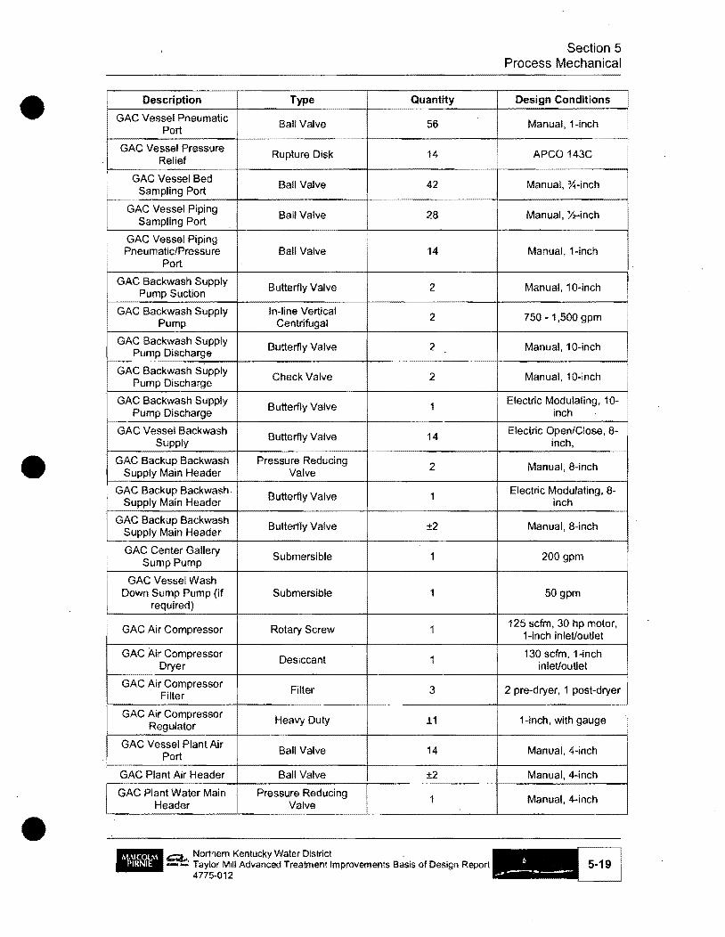
•
t
•
Description Type Quantity
GAC Vessel Pneumatic Ball Valve 56
Port
GAC Vessel Pressure Rupture Disk 14
Relief
GAC Vessel Bed Ball Valve 42
Sampling Port
GAC Vessel Piping Ball Valve 28
Sampling Port
GAC Vessel Piping Pneumatic/Pressure Ball Valve 14
Port
GAC Backwash Supply Butterfly Valve 2
Pump Suction
GAC Backwash Supply In-line Vertical 2 Pump Centrifugal
GAC Backwash Supply Butterfly Valve 2
Pump Discharge
GAC Backwash Supply Check Valve 2
Pump Discharge
GAC Backwash Supply Butterfly Valve 1
Pump Discharge
GAC Vessel Backwash Butterfly Valve 14
Supply
GAC Backup Backwash Pressure Reducing 2 Supply Main Header Valve
GAC Backup Backwash. Butterfly Valve 1
Supply Main Header
GAC Backup Backwash Butterfly Valve ±2
Supply Main Header
GAC Center Gallery Submersible 1
Sump Pump
GAC Vessel Wash Down Sump Pump (if Submersible 1
required)
GAC Air Compressor Rotary Screw 1
GAC Air Compressor 1
Dryer Desiccant
GAC Air Compressor Filter 3 Filter
GAC Air Compressor Heavy Duty ±1 Regulator
GAC Vessel Plant Air Ball Valve 14
Port
GAC Plant Air Header Ball Valve ±2
GAC Plant Water Main Pressure Reducing 1
Header Valve
_ Northem Kentucky Water District . • ='!:: Taylor Mill Advanced Treatment Improvements Basis of Design Report
4775-012
Section 5 Process Mechanical
Design Conditions
Manual. 1-inch
APCO 143C
Manual, 'X-inch
Manual, Yz-inch
Manual, 1-inch
Manual, 10-inch
750 - 1,500 gpm
Manual, 10-inch
Manual, 10-inch
Electric Modulating, 10-inch
Electric Open/Close, 8-inch,
Manual, 8-inch
Electric Modulating, 8-inch
Manual,8-inch
200 gpm
50gpm
125 sefm, 30 hp motor, 1-inch inlet/outlet
130 sefm, 1-inch inlet/outlet
I
I
i
2 pre-dryer, 1 post-dryer I
1-inch, with gauge
Manual,4-inch
Manual, 4-inch
Manual, 4-ineh

• Description Type Quantity
GAC Plant Water Main Butterfly Valve ±2
Header
GAC Vessel Plant Ball Valve 14
Water Port
GAC EQ Basin
GAC Dewatering Submersible 2
Pumps
GAC Dewatering Pump Check Valve 2 Header
GAC Dewatering Pump Plug Valve 2' Header
•
• a. ~ Northern Kentucky Water District • , --: Taylor Mill Advanced Treatment Improvements Basis of Design Report
4775-012
Section 5 Process Mechanical
Design Conditions
Manual,4-inch
Manual,4-inch
300 gpm
8-inch
8-inch
5-20 I

•
•
6. HVAC
6.1. Introduction
The HV AC portion of the project involves heating and ventilation of the. new Preliminary Treatment Building~ heating and ventilation of the new GAC Feed Pump Station pump room; heat and air condition the pump station electrical room; heating, air conditioning and dehumidification of the GAC vessel area, truck aisle, and maintenance storage area of the new GAC Building; heat and air condition the control room, conference room, lobby, and electrical room of the GAC Building.
6.2. Design Approach
Simple heating will be provided by gas fired unit heaters; Plain ventilation will be by exhaust fan with wall louvers. Large area air conditioning/dehumidification will be by split system air cooled condensing unit and central air handler unit with ductwork and diffusers. Individual room air conditioning will be by air cooled split system heat pumps and ductless split system heat pumps. Toilet and janitor room exhaust will be by individual ceiling exhaust fans.
6.3~ Facilities
6.3.1. Proposed Preliminary Treatment Building
Heating of the proposed Perliminary Treatment Building will be by individual gas fired unit heaters spaced around the perimeter of the proposed building. Ventilation will be by exhaust fans with wall mounted motor operated louvers.
6.3.2. Proposed GAC Feed Pump Station
Heating of the pump room will be by individual gas fired unit heaters. Ventilation will be provided by exhaust fans with wall mounted motor operated louvers. The electrical room shall be air conditioned by an air cooled split system heat pump and air handler with auxiliary electric heating coiL NKWD has requested the use of ceiling fans be evaluated
6.3.3. Proposed GAC Building
The GAC vessel area, truck aisle, and maintenance storage area will be heated by individual gas fired unit heaters spaced around the perimeter of the areas. The air conditioning/dehumidification will be provided by an air cooled split system condensing unit and a central ,air handler unit with a ductwork and diffuser air distribution system.
• The control room, conference room, and lobby will be served by individual ductless split
Northern Kentucky Water District Taylor Mill Advanced Treatmenllmprovements Basis of Design Report 4775-012

•
•
•
Section 6 HVAC
system heat pump condensing units and air handlers, with auxiliary electric heater coils. The toilet and janitor rooms will be provided with ceiling mounted exhaust fans to meet code. The electrical room will be ventilated to and from the GAC vessel room.
6.4. Materials t Equipment and Systems
6.4.1. Materials Table 6-1
Materials of Construction
Area Atmosphere (1) Equipment Materials of Construction or System
Process Corrosive Ductwork FRP/SS ,.. Pipinq Coated S/coated CU Equipment Coated GS/AI/SS/FRP
Process Non-Corrosive • Ductwork AI • Piping S/CU
Equipment Coated GS/AI
I Chemical Storage Corrosive Ductwork FRP Piping Coated S/coated CU/PVC/CPVC
, Equipment FRP i
! Chemical Storage Non-Corrosive Ductwork AI Piping S/CU/PVC/CPVC Equipment Coated GS/AI
Ad mi n istration Non-Corrosive Ductwork AI Piping S/CU Equi(?ment GS
Toilet Rooms Non-Corrosive· Ductwork AI Piping S/CU Equipment AI
Table Notes and Abbreviations: (1) - Corrosive areas are areas that have elevated levels of moisture, hydrogen sulfide or chemical vapors. FRP - Fiberglass Reinforced Plastic SS Stainless Steel (Type 316)\ S - Steel GS - Galvanized Steel AI Aluminum CU - Copper ~
PVC Polyvinyl Chloride CPVC Chlorinated Polyvinyl Chloride
6.4.2. Equipment
Heat pumps and condensing units shall be standard outdoor, pad mounted condensing units with condensing coils and fans. Air handling units will have a supply fan, evaporator coil, air filter, intake and supply air plenums and grilles/diffusers. Air handling unit for dehumidification shall have a supply fan, air filter, evaporator coil, hot gas reheat coil, return air plenum and grille and a supply air duct collar. Gas unit heaters shall have stainless steel burners and heat exchangers and shall have propeller fans. Exhaust fans for ventilation shaH be sidewall propeller type with wall housing, motor guard, motor operated shutter and weatherhood with birdscreen. Toilet exhaust fans shall
_ Q.. Northern Kentucky Water District -...: Taylor Mill Advanced Treatment Improvements Basis of Design Report
4775-012 6-2

•
•
•
Section 6 HVAC
be ceiling mounted with grille, exhaust duct and wall exhaust cap. Wall louvers shall be combination drainable type with motor operator.
6.4.3. Systems
Air conditioning and dehumidification systems shall be direct expansion split system air cooled condensing or heat pump units with matching air handling units.
6.5. Design Criteria
Table 6·2 Outdoor Design Criteria
Location Elevation Cooling Criteria (Ft) (ASH RAE 1%)
DB WB CDD (ASH RAE)
Covingtonl rF) rF)
Cincinnati lAP, 876 KY
91.0 74.4 3,488
Table Abbreviations:
Heating Criteria (ASHRAE 99.6%)
D8 HDD (ASHRAE) (OF)
1 5,248
ASHRAE - American Society of Heating, Refrigeration and Air Conditioning Engineers. 2001 DB - Dry Bulb Temperature WB - Wet Bulb Temperature CDD - Cooling Degree Days (50°F basis) HDD - Heating Degree Days (65"F basis)
Table 6-3 Mechanical System Criteria
, Space Cooling (OF) Cooling Method Heating or Area (OF)
Process Area
I 92 Exhaust fan wI wall 55
louver
Electric Rm wNFD 75 AC 55
Electric Rm wlo 92 Exhaust fan wI wall 55 VFD louver
Table Abbreviations: AC/Hr - Air Changes per Hour 11 T - Temperature Rise OA - Outside Air
6.5.1. Miscellaneous Design Criteria
6.5.1.1. Controls
Heating Ventilation Basis Method
Gas unit 12 AC/Hr or I1T = heaters 10°F
(100% OA) Electric duct 6 AC/Hr min coil I (0% OA) Gas unit 112 AC/Hr or I1T = heaters 10°F
! (100% OA)= 10~F
Gas fired unit heaters will be controlled by a remote wall mounted thermostat with adjustable set point to operate when the room temperature falls below the thermostat set
c:;;:t.. Northern Kentucky Water District -- Taylor Mill Advanced Treatment Improvements Basis of Design Report
4775-012
! i

•
•
•
Section 6 HVAC
point and to cease operations when the room temperature rises 2 degrees above the set point. Ventilation exhaust fans shall be interlocked with the wall mounted motor operated louvers and shall be controlled by a remote wall mounted thermostat with adjustable set point to operate when the room temperature rises above the thermostat set point and to cease operation when the room temperature falls 2 degrees below the set point. The individual room air conditioner heat pump units shall be operated by a 7-day programmable heating/cooling thermostat with set-up and set-back capability and manual change over. The air conditioner/dehumidification unit shall have a space mounted humidistat and a space mounted cooling thermostat which will operate in series to control the humidity and temperature of the area. The space mounted humidistat shall be set at 50 degrees F dew point (adjustable), and will close contact on a rise in humidity. If the space dew point rises above 50 degrees F. and there is a call for cooling, the unit will operate in cooling mode. If the space dew point is above 50 degrees F. and the thermostat issatisfied, the unit will operate in dehumidification mode. The unit will run the compressor to cool the incoming air below 50 degrees F. and use a modulating hot gas reheat coil to reheat the air to an adjustable set point. The unit fan will run continuously.
6.5.1.2. Louver Sizing
.. Intake Louvers - 500 feet per minute
III Exhaust Louvers - 700 feet per minute
6.5.1.3. Ductwork Sizing
Friction Rate Sizing:
II1II Low Pressure: 0.1 inches of water column pressure drop per 100 feet of ductwork up to an air velocity of 1,500 to 1,800 feet per minute.
II Medium Pressure: 0.2 inches of water column pressure drop per 100 feet of ductwork up to an air velocity of2,000 to 2,500 feet per minute.
II Transfer Ducts: 0.03-0.05 inches of water column pressure drop per 100 feet of ductwork.
1112 O.A Intake Shafts: 0.05-0.10 inches of water column pressure drop per 100 feet of ductwork up to an air velocity of 1,000 feet per minute.
iii Gravity Relief Shafts: 0.03-0.05 inches of water column pressure drop per 100 feet of ductwork up to an air velocity of 1,000 feet per minute.
6.6. References
6.6.1. Codes
The design of this project will be governed by the following codes:
II The Kentucky Building Code, 9th Edition, 2007.
_ Q.. Northern Kentucky Water District . • • -...: Taylor Mill Advanced Treatment Improvements Basis of Design Report
4775-012

•
•
•
Section 6 HVAC
II International Mechanical Code
• International Fuel Gas Code, 2006.
6.6.2. Standards
The following standards and guides will be used for the mechanical design of this project:
• ASHRAE (American Society of Heating, Refrigerating and Air Conditioning Engineers)
• SMACNA (Sheet Metal and Air Conditioning Contractors' National Association)
• ACGIH (American Conference of Governmental Industrial Hygienists) Industrial Ventilation Manual of Recommended Practice
• NFP A (National Fire Protection Association)
6.7. Miscellaneous
6.7.1. Dehumidification
High relative humidity in summer months make it necessary to dehumidify the GAC Vessel area to prevent condensation from forming on the vessels and piping. Sizing and type of dehumidifier will be established as the design progresses.
6.7.2. Calculation Software
• Heating and Cooling Load Analysis: Carrier E20-II Block Load or Hourly Analysis Program (HAP)
_~ Northem Kentucky Water Districl _ • -...: Taylor Mill Advanced Treatmenllmprovements Basis of Design Report ~
4775-012 6-5 I
•
'.
•
7. Plumbing
7.1. Introduction
This section describes plumbing services for the Preliminary Treatment Building, GAC Feed Pump Station, and the GAC Building.
7.2. Design Approach
7.2.1. General
It is anticipated that the plumbing requirements for the project will be for the most part simple floor drains with gravity flow to the existing sanitary sewer system and hose stations for washing down the floor area. There will be a toilet room and a janitor room with a small water heater. The GAC Building is classified as a F -1 Construction by the State HBC Office. The final shape and size of the building has not been determined at this time. If the total area is over 12,000 square feet sprinklers will be required. If it is less than 12,000 square feet, sprinklers will only be required if the material safety data sheet for the GAC is listed as hazardous
7.2.2. Preliminary Treatment Building
Hose bibb and hose rack stations will be provided at designated locations around the basins for use in wash-down of the area. A backflow preventer will be provided for this building if the existing plant water system in the tunnel does not already have one.
7.2.3. GAC Feed Pump Station
Floor drains and a hose bibb and hose rack station will be provided in the pump room. A backflow preventer will be provided in the pump room if the source of supply does not already have one. No plumbing facilities will be installed in the electrical room.
7.2.4. GAC Building
Several floor drains will be installed in the GAC vessel area with hose bibb and hose rack stations located at designated points around the area perimeter. A trench drain will run the length of the truck aisle and drain to the sanitary sewer. A men's and women's toilet room will be provided with a wall mounted water closet and a wall mounted lavatory, with access through the lobby area. The janitor room shall have a floor mounted mop sink, a tankless water heater, wall moun~ed water Closet and will only be accessible through the GAC Vessel area. A plumbing system backflow preventer will be provided in the building. All sanitary drains will flow by gravity to a nearby sanitary sewer manhole .
~, -- Northern Kentucky Water District Taylor Mill Advanced Treatment Improvements Basis of Design Report 4775-012 '
•
•
•
Section 7 Plumbing
A process main will be tapped into the existing main on Grand Avenue. This process main will be tapped inside the GAC building for water supply to plumbing fixtures. It is reported that the pressure on the process main is greater than 200 psi. It is necessary to install a pressure reducing valve on the plumbing system supply.
7.2.5. Design Criteria
SERVICE WATER SYSTEM:
• Water Source: City Water
• System Capacity: 300 GPM
• System Pressure: 100 PSI
• Hydrostatic Test Pressure: 200 PSI
COMPRESSED AIR SYSTEM:
• Type of Compressor: Oil less Rotary Screw
• System Capacity: 100 CFM
• System Pressure: 125 PSI
• Air Quality: Dry Air @ Pressure Dew Point of 33 of
FIRE SPRINKLER SYSTEM:.
• Occupancy Classification: Light Hazard
• Type of System: Wet Automatic.
• Area of Sprinkler Application: 1500 Sq. Ft. (test area for ca1culating fire flow requirements)
• Design Density: 0.1 GPM/Sq. Ft.
• Sprinkler Requinnents Per Building Size: Sprinklers may be required if the building is over 12,000 SF .
Q.. Northern Kentucky Water District _ -...: Taylor Mill Advanced Treatment Improvements Basis of Design Report
4775-012 7-2 I

•
•
•
7.3. Materials, Equipment and Systems
7.3.1. Materials
Area
Process
Process
~~.-,.~
Chemical Storage & Laboratory
Chemical Storage
Administration
Administration -Toilet Rooms
Table 7-1 Materials of Construction
Atmosphere (1) Equipment Materials of Construction or System
Corrosive Piping SS/GS/CU/ALlHCI/CU/CPVC
Equipment Coated GS/AI/SS/CU
Non-Corrosive Piping CU/BS/CIIDI
Equipment Coated GS/AI
Corrosive " Piping HCI/SS/CU/CPVC
Equipment SS/AL
Non-Corrosive Piping BS/DI/CS/CU/PVC
Equipment Coated GS/AI
Non-Corrosive Piping GS/BS/CU/DIIPVC
Equipment GS/CS
Non-Corrosive Piping CU/BS/CIIPVC
Equipment CU/DI/CI .... h~'_
Table Notes and Abbreviations:
Section 7 Plumbing
(1) - Corrosive areas are areas that have elevated levels of mOisture, hydrogen sulfide or chemical vapors. PVC - Polyvinyl Chloride SS - Stainless Steel (Type 316) GS Galvanized Steel AI- Aluminum CU - Copper CI - Cast Iron 01 Ductile Iron BS Black Steel ,
HCI High Silicon Cast Iron CS - Carbon Steel CPVC - Chlorinated
7.3.2. Equipment
Chloride
The water closet will be a wall hung type with flush valve. The lavatory will be a vitrified china wall mounted type with a single handle faucet. The mop sink will be a floor mounted molded stone construction type with wall mounted faucets. The water heater will be a tankless on-demand point-of-use device.
7.3.3. Systems
If a sprinkler system is required, it will be a simple wet pipe system. A fire pump system will not be required.
7-3 I
_ Q.. Northern Kentucky Water District . • --: Taylor Mill Advanced Treatment Improvements Basis of Design Report
4775-012
•
•
•
7.4. References
7.4.1. Codes
The design of this project will be governed by the following codes:
• Kentucky State Building Code, 9th Edition, 2007,
• Kentucky State Plumbing Code, 2007.
7.4.2. Standards
Section 7 Plumbing
The following standards and guides will be used for the plumbing design of this project:
• ANSI (American National Standard Institute)
• ASPE (American Society of Plumbing Engineers)
• ASTM (American Society for Testing and Materials)
• A WW A (American Waterworks Association)
• CISPI (Cast Iron Soil Pipe Institute)
• NFPA (National Fire Protection Association)Miscellaneous
7.5. Miscellaneous
There is an existing wash down hydrant on the top of the tunnel. This hydrant will be removed. Its function will be replaced by new wash stations inside the new Preliminary Treatment Building .
Q... Northern Kentucky Water District -- Taylor Mill Advanced Treatment Improvements Basis of DeSign Report
4775-012 7-4

•
•
•
8. Electrical
8.1. Introduction
Electrical service for the facilities in this Contract will come from the newly constructed substation that was built for the LTV disinfection project by Duke Energy. That substation will be modified as part of this work, as the load at the WTP will increase with these new facilities. The new facilities requiring electric service are the GAC Building, GAC Feed Pump Station and the Preliminary Treatment Building.
8.2. Design Approach
8.2.1. General
Power distribution will be arranged in a simple radial fashion, utilizing 480/277 volts, 3 phase for service to the facilities. One main feeder shall be run from the substation to the GAC Building main switchboard (or MCC ifloading is less than 2500 amperes). The GAC Feed Pump Station shall be subfed from the GAC Building. LTV disinfection equipment is to be relocated from the Existing Filter Building to the new GAC Building as part ofthis work. Each of these buildings shall have step-down transformers and panelboards for serving small power needs for such loads as lighting and. HVAC.
The new Preliminary Treatment Building equipment shall be powered from the existing UV disinfection panelboard in the Filter Building Basement Tunnel, specifically Power Panel PPL-l.
8.2.2. Proposed Facilities
The new facilities include the following specific electrical scope items:
• Modifications to existing switchboard SWBD-l in the yard.
• Modifications to existing electrical vault below SWBD-l.
• Modifications to panelboard PPL-I the filter pipe gallery tunne1.
• Relocation of UPS-I from the filter pipe gallery tunnel to the new GAC Building.
• Relocation ofPPU-l from the filter pipe gallery to the new GAC Building.
• Relocation ofUV system control panels UVUVL-I and UVUVL-2 to the GAC Building from the filter pipe gallery,
• Rapid mix, Flocculation and Sedimentation Basin drives motor controls and VFD's.
• Transformer and service panel for Preliminary Treatment Building.
Q... -- Northern Kentucky Water District Taylor Mill Advanced Treatment Improvements Basis of Design Report 4775·012
•
•
•
Section 8 Electrical
• GAC Feed Pump Station Main Distribution Panelboard, transformer and service panel.
• GAC Feed Pump VFD's.
• GAC Building Main Switchboard or MCC with motor controls, transformer and service panel.
• Preliminary Treatment Building, GAC Building and GAC Feed Pump Station wi1l be provided with wiring and equipment for interior and exterior lighting, HV AC, duplex receptacles inside and out for plug-in devices, and control wiring for process equipment into the SCADA system.
• Branch circuits and feeders to a1l process equipment designed as part of this project.
• No site lighting standards are proposed. All site lighting to be wall mounted as part of an associated building.
• The buildings access control system will match that of the existing buildings.
• No standby power is provided except for egress lighting in the form of internal batteries.
• Three security cameras will be provided. A fire alarm will be provided ifrequired by regulations. .
• Fiber Optic communications cab1ing shaH be provided for SCADA system interconnection with the Plant PLC.
• One ~ inch conduit with fiber optic communications cable shall be provided to existing telephone service entrance for telephone service in the conference room of the GAC Building.
• Data cables and conduits and power supply shall be provided for field instruments.
8.2.3. Constraints
A separate project by NKWD to design standby power for this WTP using a different design team and potentially being on similar schedules will be a constraint on the work. At this time, it is our intent that our work not interfere with the standby power concept laid out in the UV disinfection project by B&V in 2006.
8.2.4. Staging
It is the design team understanding that chlorine can be used as the only disinfecting agent on a temporary basis during the time that the UV disinfection equipment is relocated to the GAC Building. Chlorine disinfection alone will also be required during the time that the UV disinfection substation is down for modifications at the substation to provide a power feeder to the GAC Building. There should be no other unusual power interruptions except short duration tie-ins.
------_ ... _- .... _---------------Q.. Northern Kentucky Water District -....: Taylor Mill Advanced Trealmenllmprovements Basis of DeSign Report
4775-012 8-2

• 8.2.5. Energy Efficient Design
Section 8 Electrical
Kentucky Building Code requires compliance with the International Energy Conservation Code (IECC), which requires all spaces to have at least manual control of lighting in each space, and where more than one fixture is used, two levels of switching to reduce the level of light by 50 percent. Further, buildings larger than 5000 square feet are required to have automatic controls to tum off the lights during unoccupied periods, either by timer or occupancy sensor (with a manual local override).
The IECC also mandates a maximum wattage per square foot for interior lighting, but offers no category for a water treatment plant. The most similar category among those offered is a Manufacturing Facility at 1.3 watts per square foot and for the office area in the GAC Building 1.0 watts per square foot. These numbers will be used in calculations submitted to the Department of Housing, Building and Construction when applying for plan review.
Exterior lighting will be limited to 5 watts per linear foot of each illuminated wall and walkways 1.0 watt per linear foot. Main entry doors may be illuminated to 30 watts per linear foot of door width, other doors to 20 watts per linear foot of door width.
Motors will be energy efficient, and use of variable frequency drives on the large GAC Feed Pumps assures that power factor will be high and only the needed horsepower for
• driving the load is consumed.
•
8.2.6. Area Classification
• The electrical vault in the yard is considered a permittable confined space.
• The GAC Feed Pump' Station shall be considered a wet location.
• The GAC Building process area shall be considered a wet location.
• The Preliminary Treatment Building and pipe tunnel are considered wet locations.
• No areas are considered as hazardous locations requiring compliance with NEC Article 500.
8.2.7. lighting
• In order to meet energy code requirements, lighting must be HID or fluorescent.
• Exit signs, if required, will be LED type.
• All lighting in wet locations will be enclosed and gasketed, NEMA 4X rated.
• Lighting in office areas shall be commercial quality, designed to match the finish schedule.
8.2.8. Design Methods
• Lighting will be modeled utilizing Visual lighting software for a11 interior spaces.
~ Northern Kentucky Water District _ -...: Taylor MUI Advanced Treatment Improvements Basis of DeSign Report ~
4775-012 8-3 I

•
•
•
Section 8 Electrical
• Short circuit analysis, if required, will be performed utilizing SKM Power Tools software.
• Voltage drop calculations will be manually performed to confirm wire selections on long feeders.
• During detailed design, load analysis in accordance with the NEC shall be performed by the Electrical Engineer of Record to prove final sizing.
.• Comcheck software shall be utilized to document energy code compliance to the State Department of Housing, Building and Construction.
8.3 .. Materials, Equipment, Systems
8.3.1. Materials
All power conductors for branch circuit and feeder wiring shall be THW or TH\VN/THHN insulated, #12 minimum, copper. All raceways shall have an additional conductor pulled for grounding and bonding, instead of depending on the in~egrity of the raceway continuity.
Instrumentation cables shall be individual # 16 shielded and twisted pairs, rated 600 volts. All instrumentation and signal cables that are shielded shall have the shield bonded on one end only (and insulated on the other end to prevent accidental intermittent grounding of both ends). Communications cables for Ethernet communications shall be CAT 6.
All conduits in finished spaces shall be concealed. Conduit in process areas, electrical and mechanical equipment rooms shall be exposed. All exterior conduits shall be underground.
Exposed conduit shall be galvanized rigid steel or rigid aluminum. Flexible conduit shall be liquidtight in all process areas. Underground conduit shall be schedule 40 PVC direct burial. . A minimum of one general purpose 120 volt, 20 ampere duplex receptacle outlet shall be provided in every room of the new buildings.
Roof, mechanical equipment service and other receptacles shall be provided as required in the NEC. Weatherproof receptacles shall be weatherproof while in use. All exterior receptacles to be ground fault circuit interrupting .
. Grounding electrodes will be designed to exhibit less than 5 ohms resistance. A new ground reference is required at each separately derived system, which can be individual transformer outputs, main electric service, as well as supplemental ground references which may be established for such things as signal reference or lightning protection systems. In order to prevent any objectionable currents, all such grounding electrodes should be interconnected with each other to form one continuous reference.
_ Q.. Northern Kentucky Water District _ . • -...: Taylor Mill Advanced Treatment Improvements Basis of Design Report 8-4
4775-012 -!

•
•
•
Section 8 Electrical
Buried, concealed or concrete encased grounding electrode connections shall be made using exothermic welds.
Each new building shall have a grounding electrode system that consists of the following:
• A minimum lO-foot length of buried metal water line, if available.
• Metal Frame of the building. if avai lable.
• A minimum 20 foot length of at least Y2 inch diameter steel reinforcing rod near the bottom of the foundation footing for the building.
• A ground ring encircling the building at a depth of at least 30 inches, at least 20 feet in length, bare copper conductor, no smaller than #2 A WG.
• Driven ground rods, 3/4 inch diameter, 10 feet in length, fully driven in the ground at locations where required for lightning down conductor grounding.
All the above items shall be bonded together utilizing a grounding electrode conductor sized in accordance with NEC article 250.66. All such grounding electrode conductors shall be copper. They shall be sleeved with PVC conduit into the respective buildings where they are to be landed in the equipment.
8.3.2. Equipment
SWITCHBOARD
The main service equipment at theUV substation shall utilize low voltage front access only switchboard, non walk-in sloped roof exterior constt:Uction. This low voltage switchboard will be rated for 480/277 volt, 3-phase, 4-wire service. Bus bars will be silver plated copper. A TVSS unit shall be included as described below.
The incoming service section of the main switchboard shall include an electronic circuit monitor with local display unit, to facilitate Facilities Management staff viewing of key electrical parameters such as incoming voltage and amperage per phase. The electronic circuit monitor shall be provided with management software and Ethernet communications connection to allow future remote interface with the SCADA system.
MOTOR CONTROL CENTER
Motor Control Centers (MCC's) will be utilized whenever economics justify based on a structure having numerous 3-phase motors that require remote control and motor starters. Individually mounted or MCC mounted combination motor starters will utilize magnetic only circuit breakers and ambient compensated thermal overload relays. GAC Feed Pumps will be started utilizing variable frequency drives (VFD's) furnished with the equipment. The 12 flocculators and the two new rapid mixers shall also be controlled using individual VFD's.
~ Northern Kentucky Water District • - .. .: Taylor Mill Advanced Treatment Improvements Basis of DeSign Report
4775-012 8-5

•
•
•
Section 8 Electrical
PANELBOARDS
Panelboards will be provided with copper or copper-clad aluminum bus bars and will utilize bolt-on, thennal magnetic type circuit breakers. Panelboards will be located in electrical rooms wherever possible.
Ground-fault interrupting circuit breakers wiJ] be installed in lieu of ground-fault interrupting receptacles where most cost effective.
DRY TYPE TRANSFORMERS
Dry type transfonners will be provided for 120/208V, 3-phase, 4-wire applications such as small appliances, receptacles, water coolers, telecommunications equipment, small HV AC equipment, field instruments, etc.
All transfonners will be delta-wye connected, in order to prevent unwanted circulating currents, and will be solidly grounded on the secondary neutral.
SURGE PROECTION DEVICES
Transient Voltage Surge Suppressors will be provided to protect critical loads against unwanted electrical surges which occur over the wiring in the facility, due to motor starting, switching and offsite lightning strokes which enter through the utility service, or onsite lightning strokes which hit buried ductbanks or the building structure .
Transient Voltage Surge Suppressors (TVSS) will be hybrid type, offering MOV technologies, for high speed and high power dissipation. Two levels ofTVSS will be provided, one at the building service level, and the other at the switchboard/panelboard level. The device at the service will be rated higher power and allow a higher let through voltage than the unit located at the switchboard/panelboard. Panelboard TVSS units will lower the transient let through voltage to levels that will satisfy industry standards to reduce erroneous data or damage caused by externally generated transients at the equipment.
LIGHTNING PRO"rECTION SYSTEM
Direct hit lightning protection shall be provided in the fonn of an air terminal system. The system will be designed in compliance with NFP A Standard 780, UL Standard 96A, and Lightning Protection Institute (LPI) Standards. The system shall be installed by a UL listed installer, LPIcertified, and at substantial completion the building shall have a UL Master Label affixed near the main entry door to the at grade main entry to the three new buildings or some other mutually agreed location.
A system of air tenninal points will be provided in accordance with UL 96A and NFP A 780 guidelines. Air tenninals will be connected by cross conductors and down conductors to offer two paths to ground. Any metal object which is closer than 6 feet to an air
Q.. Northern Kentucky Water District _ -...: Tay!or Mill Advanced Treatment Improvements Basis of Design Report
4775-012 . 8-6 ,I

.'
•
Section 8 Electrical
---------------_ ..... _-----------
tenninal, grounded conductor, or down conductor, shall be bonded to the grounded conductor to prevent sideflash during conduction.
The down conductors will be exothennically bonded to the counterpoise that is used for creating the power distribution system-grounding electrode. Where a lightning protection down conductor attaches to this counterpoise, a driven ground rod will also be connected exothennically.
8.3.3. Systems
The types of systems proposed shall be corrosion resistant and industrial quality, UL listed as an assembly. Specifically:
• Outdoor Switchboard NEMA 3R enclosed non walk-in construction
• Panelboards - NEMA 12 enclosed, bolt-in branch breakers
• MCC - NEMA I enclosed, 20 inch deep sections
• Equipment disconnects in the field NEMA 4X, 600 volt heavy duty
• VFO in pipe gallery - NEMA 4X enclosed
8.4. References
8.4.1. Codes
The electrical design will be governed primarily by the following codes:
• National Electrical Code.
• Kentucky Building Code.
• National Electrical Safety Code.
8.4.2. Standards
The following primary standards will be used for the electrical design ofthis project:
• ANSI (American National Standard Institute)
• IEEE (Institute of Electrical and Electronic Engineers)
• UL (Underwriter's Laboratories)
• NFPA (National Fire Protection Association)
• Others will be added to specifications as detailed design occurs.
8.5. Miscellaneous
8.5.1. Existing Conditions
In order to complete the detailed design, it will be necessary to verify in the field, actual • layout, electrical characteristics and dimensions of all UV equipment to be relocated, as
_ ~ Northern Kentucky Water District -...: Taylor Mill Advanced Treatment Improvements Basis of Design Report
4775·012

•
•
Section 8 Electrical
well as UPS-I, SWBD-l, PPL-I and the electrical vault. This can be accomplished in a one day site visit. Existing drawings have been relied on solely for this report.
8.5.2. Leadership in Environmental and Energy Design (LEED) Goals
The following LEED credits can be achieved easily by our standard design procedures:
• EQ Credit 6.1 - Controllability of Systems
By providing individual local lighting controls in each space per the energy code, requirements for this credit will be met.
• SS Credit 8 - Light Pollution Reduction
By using cutoff luminaires for exterior lighting and assuring that 95 percent of interior illumination falls below the window sill on exterior rooms, requirements for this credit will be met. Alternately, interior lighting occupancy controls will comply for this credit as well if used on exterior rooms.
With direction from the Owner, it is also possible to reduce lighting energy to below requirements of the energy code to achieve LEED points under EA Credit 1, but this is a larger issue that must be worked with improvements to the building envelope and HV AC system equipment. A lighting reduction of 10.5 percent below the energy code would be easily achievable toward that end .. The necessary energy modeling to prove this has not been included in the scope of work. LEED compliance is also not a part of the scope of work .
Q.. Northern Kentucky Water District _ -...: Taylor Mill Advanced Treatment Improvements Basis of Design Report 8-8
4775-012 _

•
•
•
9. Instrumentation and Control
9.1. Introduction
It is anticipated that NKWD will upgrade the current version of Wonder ware along with a portion of the existing hardware as part of separate project prior to the construction of the Advanced Treatment Project. As of now, the details and extents ofthe upgrade are unknown, but the Advanced Treatment Project details will be coordinated with this upgrade.
9.2. Design Approach
9.2.1. Preliminary Treatment Facilities
9.2.1.1. Rapid Mix
The rapid mixers will be outfitted with VFDs located in the tunnel area. Start/Stop functionality will be provided locally at the mixers as well as at the VFD and through the SCADA System. Speed control will be provided at the VFD and remotely through SCADA. Drive status and run-time will be monitored in SCADA. Semi-automatic speed control based on setpoint G-Value and water temperature is a proposed option through SCADA.
9.2.1.2. Flocculation
The flocculators will be outfitted with VFDs located in the tunnel area. Start/Stop functionality will be provided locally at the mixers as well as at the VFD and through the SCADA System. Speed control will be provided at the VFD and remotely through SCADA. Drive status and run-time will be monitored in SCADA. Semi-automatic speed control based on setpoint G-Value and water temperature is a proposed option through SCADA.
9.2.1.3. Sedimentation
The residuals collection ofthe sedimentation basins will have local control panels located at the sedimentation basins and the MCC located in the tunneL Drives will run in Stop, Start, as well as Auto mode through timers in SCADA. Drive status and run-time will be monitored in SCADA and a drive torque overload alarm will be provided in SCADA.
Local manual control (at the valves) will be provided for residuals blowdown. Automatic and manual valve control and adjustable blowdown interval and duration will be provided in SCAD A. The collection drives will be interlocked with corresponding basin
c::;:;a... -- Northern Kentucky Water District Taylor Mill Advanced Treatment Improvements Basis of DeSign Report 4775-012
9-1

•
•
•
Section 9 Instrumentation and Control
blow down valves so collection mechanisms operate when blowdown valves are open. Only one blowdown valve will be operated at a time.
The residuals pump station float switches will be replaced with continuous level monitoring device and a new control panel will be provided. High and low level alarms, continuous water level, motor temperature, seal leakage, pump status and run time will be monitored in SCADA.
9.2.2. GAC Process
9.2.2.1. GAC Influent Pump Station
The GAC Feed Pump Station (GAC FPS) wiH receive filtered effluent from the filter effluent header. The operation strategy for the GAC FPS is to maintain an operating band within the wetwell to match the pumping capacity with the influent flow. To achieve this, each pump will be outfitted with a variable frequency drive (VFD). An ultrasonic level element will be utilized to monitor and relay the current wetwelllevei. Control of the modulating valves will be controlled by the SCADA PLC. The level setpoint wil1 be entered through SCADA. Local control of the pumps will occur through the local/remote switch on the individual VFD. Local manual speed control wi1l be available at the VFD as welL A venturi flow meter with differential pressure transmitter will be provided on the pump discharge header. The local control panel will include SCADA controls, start/stop, remote/local, run status, and speed.
9.2.2.2. GAC Contactors
Each contactor will have the foHowing automated valves:
• Influent (EOC)
• Effluent (EM)
• Waste (EOC)
• Backwash Supply (EOC)
• Influent/Effluent Isolation (EOC)
Each contactor will be provided with a strap-on style flow meter for effluent flow control on the influent header piping. Effluent flow control will be maintained through a flow control loop between the vessel influent flow meter and the modulating contactor effluent control valve. Flow control will occur through a distributed mode, where all vessels in operation will be controlled to process the same flow.
A local control panel will be provided for each pair of contactors. The local control panel will allow local control of the automated contactor valves. A local flow readout will be provided as well.
Northem Kentucky Water District _ Taylor Mill Advanced Treatment Improvements Basis of Design Report ~ 4775·012
9-2

•
•
•
9.2.2.3. GAC Backwash
Section 9 Instrumentation and Control
GAC backwash will utilize a backwash rate setpoint control loop. A modulating control valve will be provided for both sources of backwash supply, the backwash booster pumps, which take suction from the contactor effluent, and the Taylor Mill Plant Discharge, downstream of the pressure reducing valves in series. Each supply will utilize a dedicated venturi meter with differential pressure transmitter. An individual local control panel will be provided for each supply as well and will include control of the modulating valve and a local readout for backwash flow rate and backwash EQ level.
9.2.3. GAC Equalization Basin
The equalization basin will be provided with an ultrasonic level element and two dewatering pumps. The dewatering pumps will operate automatically based on level setpoints programmed in the main PLC. A local control panel will be provided for manual control as well.
9.3. Equipment
Table 9-1. Preliminary Instrument List
Description Location Type Quantity
Flow Meter GAG IPS Venturi 1 Discharge Line
I nfluent Flow Vessel Influent Strap on 14 Meter (one per Line Ultrasonic Flow vessel) Meter
Turbidimeter GAG Effluent NTU 1 Header
Level Indicating Equalization Basin Ultrasonic 1 Transmitter
Flow Meter Backwash Supply Venturi 2 Header
Differential GAG Vessel 14 Pressure Effluent Line Indicating Transmitter
Level Indicating Residuals Pump Ultrasonic 1 Transmitter Station
Q... Northern Kentucky Water District _ -- Taylor Mill Advanced Treatment Improvements Basis of Design Report ~ 9-3
4775-012 _

• , "
10. Permitting
Below is a list of pennits that will likely be required for the Project:
• KDOW Construction Pennit, submitted upon completion of design (Design Team);
• Kentucky Transportation Cabinet, Encroachment Pennit, submitted upon completion of design (Design Team);
• Sanitation District No.1 Grading, Erosion Control and/or Land Disturbance Pennit, submitted upon completion of design (Design Team);
• Public Service Commission Certificate of Public Convenience and Necessity, submitted as soon as possible after bids received (NKWD);
• Local Road/Street Encroachment Pennit, submitted upon completion of design (Design Team);
• Kentucky Housing and Building Code Enforcement Review, submitted upon completion of design (Design Team);
• Local Building Pennit, submitted upon completion of design (Design Team);
• • Plumbing Pennit, submitted upon completion of design (Design Team).
• Q.... -- Northern Kentucky Water District Taylor Mill Advanced Treatment Improvements Basis of Design Report 4775-012
10-1

•
•
•
11. Suggested Sequence of Construction -- ..... --.~---------------- ---
The suggested sequence of construction is as follows:
1. Begin construction of the GAC Building. Relocate 36" feed ifrequired, coordinate with plant shutdown.
2. Relocate the underground electric and small diameter process piping that would otherwise be disturbed during excavation for the new preliminary treatment facilities.
3. Demolish the south flocculation and sedimentation basins and excavate for the new preliminary treatment facilfties.
4. Close the existing gate that is located at the southeast comer of the north flocculation basin and divert all settled water flow to the existing 24-inch pipe that connects to the north end of the filters .
5. Demolish the top of the existing tunnel between the existing rapid mix and filter building (an area about 12 feet by 15 feet). Demolish the existing settled water channe1 that is connected to the north side of the tunnel. Temporarily leave the existing rapid mix in place.
6. Construct a new settled water channel from the north side of the tunne1 to the existing filter influent channel at the filter building wall (north of the tunnel). Construct a new top for the tunne1 between the existing rapid mix and filter building. Construct the new preliminary treatment facilities. All of this construction would take place concurrently.
7. Take the plant out of service for a short time to disconnect the raw water main from the existing rapid mix and connect it to the new rapid mix.
8. Place the new preliminary treatment facilities in service.
9. Demolish the top of the existing rapid mix basin walls. Cap existing basin with concrete.
10. Demolish and till the north flocculation and sedimentation basins. Connect the existing 24-inch settled water pipe to the new settled water trough .
11. Construct the GAC Feed Pump Station.
_ ~ Northern Kentucky Water District _ -...: Taylor Mill Advanced Treatment Improvements Basis of Design Report 11-1
4775-012 _

•
•
•
Section 11 Suggested Sequence of Construction
12. Tap the 36" high pressure distribution main from the TMTP to provide backwash and potable water to the GAC building.
13. Complete the GAC Building.
14. Following the construction ofthe GAC Feed Pump Station and prior to placing the PS into service, piping modifications and tie-ins must be completed in the existing filter building pipe gallery to the GAC Feed PS. The c1earwell will need to be drained to construct the pipe modifications in the existing "North" and "West" filter building pipe galleries. The plant will be out of service while these modifications are made.
15. Following the pipe modifications, in the existing filter building pipe galleries, and while the UV systems are being relocated utilize the emergency UV I GAC bypass in the North pipe gallery.
16. Place the GAC Feed Pump Station and GAC Building in Service.
17. At no time shall the FTTP distribution pumps be taken out of service .
~, -- Northern Kentucky Water District Taylor Mill Advanced Treatment Improvements Basis of Design Report 4775-012
11-2

•
•
•
12. Opinion of Probable Construction Costs
An opinion of probable construction costs (OPCC) was developed based on the current preliminary design. The cost opinion was developed as a Class 3 estimate in accordance with AACE guidelines and has a predicted accuracy of -20% to +30%. The summary of the opinion of probable construction costs is shown in Table 12-1 below.
Table 12·1. Opinion of Probable Construction Costs
Item Cost
Opinion Of Probable Construction Cost' $21,434,000
AACE Class 3 Estimate -20% Range $17,147,000
AACE Class 3 Estimate +30% Range $27,864,000 Note: I. The opec With GAC Bulldmg Option B lIl11eu of OptIOn A'5 $400,000 less than the above estimate costs
Since the OPCC was developed utilizing the current preliminary design, many variables and options remain; which require further evaluation. Therefore, markups and contingencies were utilized in an attempt to account for the remaining unknowns associated with this project.
The OPCC summary sheet and subsequent breakdowns of the cost, by CSI Master Format 1995 division, can be found in Appendix D. The summary sheet includes a markup of25% for the contractor's indirect costs for bonds, mobilization, insurance, overhead and profit, and contingency. An additional 11.3% (5.5% ENR annual increase in construction cost) is included to escalate the cost to the end of201 0, the middle of the construction project. In total the OPCC has been marked up 36.3% or approximately $7,700,000.
In the PreiiminGlY Design afGAe Systems Report (by Malcolm Pirnie, Inc. and GRW, Inc., dated March 2008), an opinion of probable construction cost of approximately $24,000,000 ($21,000,000 construction cost + $3,000,000 contingency) was estimated. This estimate falls within the -20% to +30% calculated at the current preliminary design stage.
Since the preliminary design report was written, various design parameters have changed. Previously, the preliminary treatment building was only to cover the flocculation and sedimentation basins. Currently, the building has been expanded to cover the entire preliminary treatment process. Additional work is also required on the tunnel roof including an additional structure/cover over the tunne1 to access the preliminary treatment
~. -- Northem Kentucky Water District Taylor Mill Adllanced Treatment Improllements Basis of Design Report 4775·012

•
•
•
Section 12 Opinion of Probable Construction Costs
building from the filter building. As part ofthe preliminary engineering stage, both the UV and GAC facilities were also reassessed. As part of this analysis, the UV disinfection system was relocated to the GAC Building. As a result of reevaluating the GAC Building, larger GAC vessels were chosen, which resulted in fewer vessels and a different building layout.
As the project progresses and the design is finalized, the OPCC will be reevaluated to provide a more accurate and narrower range of cost opinion.
~ Northern Kentucky Water District -....: Taylor Mill Advanced Treatment Improvements Basis of Design Report
4775-012 12-2

•
•
• 4775-012
Northern Kentucky Water District
Appendix A: Figures Figure 2 - 1 Figure 3 - 1
Figure 3 2
Figure 3 - 3
Figure 3 - 4 Figure 3 - 5 .
Figure 3 - 6 Figure 3 7 Figure 3 - 8
Figure 5 - 1 Figure 5 - 2
Figure 5 - 3 Figure 5 - 4 Figure 5-5
Figure 5 - 6 Figure 5 - 7
Site Plan
Architecture Preliminary Treatment Elevation
Architecture GAG Plan "A"
Architecture GAG Elevation "A"
Architecture GAG 3-D Rendering "A" Architecture GAG Plan "B" Architecture GAG Elevation "B" Architecture GAG 3-D Rendering "B"
Architecture GAG Feed PS Elevation Hydraulic Profile Preliminary Treatment Process Flow
GAG Feed PS & Building Process Flow GAG Backwash Process Flow Preliminary Treatment
GAG Feed Pump Station GAG Building
~. GRIM...'nc.
MALCOLM PIRNIE

•
•
•
MALCOLM PIRNIE
1.0 BACKGROUND AND PURPOSE
STRUCTURAL EV ALUA TION OF THE EXISTING TUNNEL
TAYLOR MILL TREATMENT PLANT TECHNICAL MEMORANDUM
The existing flocculation and sedimentation basins will be demolished and replaced due to severe deterioration of the concrete which is about 50 years old. NKWD's decision to replace the basins was based on the findings and recommendations contained in a May 2006 study by Black & Veatch. The Black & Veatch study focused on the water holding walls and troughs that are above grade and exposed to freezing temperatures. A basin diagram in the report indicates that the exposed walls should be replaced but the tunnel is to remain. However, the report did not contain an explicit recommendation that the tunnel remain in place.
The purpose of this evaluation is to determine whether the tunnel should continue to ren~ain in service or be demolished and replaced.
2.0 FINDINGS OF THE 2006 STRUCTURAL EVALUATION
The Black & Veatch study concluded that the exposed water-holding walls deteriorated due to moisture in the concrete (which was not air entrained) and exposure to a large number of freeze/thaw cycles.
During the Black & Veatch study several concrete cores were obtained and tested. One core was obtained from the north tunnel wall and tested. The concrete in this core was concluded to be in good condition.
3.0 OBSERVATIONS
Krish Narayanappa, a GRW senior structural engineer, inspected the tunnel on November 10,2008. Steve Vogelsberg accompanied Mr. Narayanappa.
The following observations were made:
• One crack 3 to 4 feet long was observed in the top of the south wall at the east end of the tunnel. No other cracking of the walls was observed. .
• There was a leak in the bottom of the south wall at the east end of the tunnel.
• There was one crack in the underside of the tunnel concrete roof which appeared to be caused by a pipe hanger anchor which has pulled out a section of concrete.
• The top of the tunnel concrete roof appeared to have some hair-line cracks but it was covered with a thin coat of topping so it was difficult to assess the condition of the concrete.
lU\3789\RErORT$ ANDSr<';[)IIiS\TUN"E;L TECHNICAL MEMORANDUM\ TUNNEL TECHNICAL ~IEMORANDUM

•
•
•
Appendix B
• The east end of the tunnel concrete roof in the vicinity of the rapid mix and concrete channels is in poor condition .
• 4.0 PRELIMINARY EVALUATION
Based on the field observations, the north and south walls of the tunnel appeared to be in good condition and should provide adequate future service as non-water-holding walls. However, it was difficult to fully assess the condition of the concrete on the outside which was submerged and on the inside which was painted. It was also difficult to assess the condition of the tunnel roof which had been coated with topping. Therefore, it was decided to obtain and test additional concrete cores from the tunnel roof and walls.
5.0 CONCRETE TESTING
On December 17, 2008 Thelen Associates obtained the following concrete cores:
• Two cores from the inside face of the north wall • Three cores from the inside face of the south wall • Three cores fonn the upper surface of the tunnel roof
The tested compressive strength of the cores varied from 5,830 to 12,200 PSI. This exceeds the compressive strength required for new concrete. The test results are attached.
6.0 CONCLUSIONS AND RECOMMENDATIONS
Based on the field observations and test results, it is concluded that the walls and western three fourths of the tunnel roof can remain in service for an extended period of time. It is recommended that the highly deteriorated areas on the east end of the tunnel roofbe removed and replaced. Careful consideration should be given to construction staging to keep the plant in service during construction.
2
IU\37B9\REPORTS Al\;D STUDIES\ T\;NNEL TECHN1CAL ~[EMOR .. r-;DliM\ TUNNEL TECHNICAL MEMORANDUM
•
•
• 4775-012
Northern Kentucky Water District
Appendix C: Existing UV Evaluation . Technical Memorandum
~. Gil", Inc.
MALCOLM PIRNIE

•
•
•
MALCOLM PIRNIE
Date:
To:
From:
Re:
January 29, 2009
Amy Kramer, P.E., NKWD
Jason M. Abbott. P.E.
TMTP Existing UV Evaluation
Technical Memorandum
Project No.: NKWD Taylor Mill Advanced Treatment Improvements Project
SUMMARY
With the construction of the proposed post filter GAe facility at the TMTP, the existing UV reactors were evaluated based on their location and current treatment parameters. We evaluated the following options:
1. Leave the UV reactors in their current location post filtration; 2. Leave the UV reactors in their current location, but provide space for future
process relocation post GAe absorption when existing reactors are replaced / removed;
3. Purchase new UV reactors and install them post GAe; 4. Relocate existing UV reactors post GAe.
It was determined that the best option was to relocate the existing UV reactors, UV electrical/control panels, and UPS from their current locations. in the pipe galleries of the existing filter building, to the proposed CAC Building.
UV LOCATION EVALUATION
This determination was based on discussions held during the Friday, November 14, 2008 and Friday, December 5, 2008 progress meetings.
During the November 14, 2008 progress meeting, it was discussed that the current electrical costs to operate the existing UV system are approximately $1,400 per month ($16,800 per year). The raw purchase price of a new UV system to operate at a UV, of 95% is approximately $400,000 (UV equipment only, excluding installation, piping, etc.). Therefore, the purchase of a new UV system is not economically warranted due to payback from electrical costs.
During the December 5, 2008 progress meeting, the remaining three options and the treatment goals associated with the UV system were discussed. It was determined that NKWD would like the UV process to be located post-CAC. NKWD also mentioned that the installation should consider the issue with the current reactor location that results in air entrainment and unit nuisance trips. Furthermore, NKWD wants to avoid running new piping through the eXisting clearwell. Other UV constraints were discussed including:

•
•
•
File
• UV redundancy required
• Full bypass of GAC desired
• Piping modifications I relocation
January 29, 2009 Page 2 of 3
• North and West filter basement gallery space limitations
• Gallery access must be maintained
Malcolm Pirnie presented three UV alternatives, which are described below. Based on the previous UV analysis, new UV reactors were not investigated as a possible alternative at the December 5, 2008 meeting.
a. The first UV alternative presented was to leave the existing reactors in their current location to receive filtered water flow. Due to the current UV configuration, this alternative requires piping modifications to accomplish the flow objectives. Additionally, utilizing the current location would not provide a solution for the current air entrainment isstJes. Another disadvantage of this alternative is that the UV does not provide an additional barrier for bacterial growth or other contamination that may occur in the GAC process. This alternative was not selected for these reasons.
b. The second UV alternative presented is similar to the first alternative, in that the UV systems would remain in their current location to receive filtered water flow, but space would be provided for future replacement of the reactors post-GAC: Due to the reasons cited for the first alternative, this alternative was not selected.
c. The third alternative presented was to relocate the UV systems post-GAC. The team presented a cost efficient alternative, which kept the UV reactors located within the filter piping galleries. This alternative would require that UV system No.2 (currently in the North pipe gallery) be relocated above UV system No.1 in the West pipe gallery and that a post-filtration effluent line pass through the clearwell to convey water to the GAC feed pump station. Relocating the UV systems, post-GAC, within the pipe galleries takes advantage of the higher UVt and allows for the bypass of the GAC vessels without having the utilize the GAC Feed Pump Station. Another advantage, by installing the reactors post-GAC, they will provide an additional barrier for bacterial growth. The main disadvantage to the this option is that a a pipe conveying filtered water with a low residual would need to be routed through the clearwell. This was a major concern for the stakeholders and this alternative was not selected.
Upon fUrther discussion, two additional UV alternatives were discussed. The first alternative was to relocate the existing reactors to the GAC Building to process GAC treated water. Relocating the UV reactors in the GAC building requires additional. footprint in the GAC Building and requires relying on the GAC Feed Pump Station. If the GAC process is bypassed, filtered water flow will have to be pumped through the UV reactors. This alternative eliminates the need for a pipe passing through the clearwell and relieves some of the congestion in the filter basement gallery. The UV

•
•
•
File January 29,2009 Page 3 of 3
reactors will be located on the GAC effluent line prior to the positive head loop to maintain submergence of the UV reactors at all times.
The second was to relocate the UV reactors to the GAC Feed Pump Station. This option requires a basement level be added for the UV equipment (to maintain submergence of the reactors at all times). This option was estimated to cost significantly more than the GAC building location and was not selected.
Based on the many advantages of relocating the UV reactors to the GAC Building, NKWD selected this alternative. This alternative will be designed with a UV /GAC bypass located in the filter basement gallery and a UV bypass located in the GAC Builidng. The slides from this progress meeting (12/5/08) have been attached for future reference.
cc: File: 4775-012
amw

•
•
•
UV Alternatives Current UV Locations
UV Alternatives North Pipe Gallery (Existing UV)
1

• UV Alternatives North Pipe Gallery (Existing UV)
2 NDIff~rn Ktm/tX~y Wats-r Distr,;:1 - Advanced Tfealment ImprovemtJrrrs Prc~wcr ~\f~" - ------ - ----- --
• UV Alternatives West Pipe Gallery (Existing UV)
• 2

•
•
•
UV Alternatives West Pipe Gallery (Existing UV)
UV Alternatives
1 . leave the reactors in their current location post filtration;
2. leave reactors in current location but provide space for future process relocation post GAC adsorption when existing reactors are removed;
3. provide Ae\IIJ reactors follo¥ling G,A..C; 11/14/08 PM
4. and relocate existing reactors post GAC
5 Nctrhe"i. kenwcA y lVarer Dl.sr'r;! - ActrW1C6d TtI).1rm~mr iJq;Jfq,.tI'l1ltl~S Pfqet:1 ~~~ .... ~~ ~
3

•
•
•
UV Alternatives Constraints
UV Alternatives
~ .---~ ,
1£ '" "'~'] I ,'IE'll
~'-J~ .~._ .. v~~ I _J
• UV bypass not allowed
• UV redundancy required
• Full bypass of GAC desired
• Tight gallery limits options
• As constructed condition requires piping modifications to accomplish flow objectives (all alternatives)
• Maintain gallery access
, -~'oO-_ •
Alternatives 1 & 2: North Pipe Gallery (Removal/Relocation)
;_1, '",v.vvvv ... H'1
_J
4

•
•
•
UV Alternatives Alternatives 1 & 2: West Pipe Gallery Removal/Relocati
UV Alternatives Alternatives 1 & 2: UV Relocation (Yard Piping)
. . . . -- , t Dc.r: .... ~ r I I'" I ~~(: 1~lr' LC~~""''''''''A~J
5

•
•
•
UV Alternat ves Alternative 4: Relocate Existing Reactors Post GAC
• Requirements: • Relocate the existing UV systems so that the filter
effluent flows to the GAC PS. The GAG PS would then pump the filter effluent through the GAG, through the relocated UV systems, and into the clearwell.
• Piping setup allows for future replacement with units sized to take advantage of higher UVT of GAG treated water.
UV Alternatives Alternative 4: North Pipe Gallery
•. UU"nI"'~IIRelocatio
6

•
•
•
UV Alterna ves Alternative 4: West Pipe Gallery wa""r~v!!lli/Relocation)
~I'-I]J~~* ~fij1lJ©~ 1fu!~®"
j
t 2 Nr;ttl>em Kenft,lOl:Y Wa;'e£D~(Jl;' - AiJyannJd Tlo.:nmem /tmrgvumwl1s PIOf9Ci ........ ~~~~ - -- ..
UV Alternatives Alternative 4: UV Relocation (Yard Piping)
Normem Kl1rWJ".~}' WarMo.'$lt'lCf- ACv!JJ'I(;(Id Tt .. .1(I~ ImtlfCIftm'en."S PrA~! 'I.~if~\t _. .
7

•
•
•
UV Alternatives UV Relocation Alternatives
Location
j Reconfigure Piping In the "North & j West Pipe Galleries"
• Additional Footpri!1t for Electrical ! & Control No
Alternative 2
No
~A~~lti~O~~a~I-F-O-Ol-p-rin-l~--~-'11~ ___ N_M ____ ~illlllllllllll·~· _____ N_/A ____ ~
8
•
•
• 4775-012
Northern Kentucky Water District
. Appendix 0: Opinion of Probable Construction Cost
~. SliM(, Inc.
MALCOLM PIRNIE

• TMTP ADVANCED TREATMENT IMPROVEMENTS: Opinion Of Probable Construction Cost Estimate Summary
Division Description Total Construction Cost % or Total
1 General Requirements $ 93,000 0.4
2 Site Work $ 1,363,000 6.4
3 Concrete $ 2,098,000 9.8
4 Masonry $ 1,116,000 5.2
5 Metals $ 291,000 1.4 (; Wood and Plastics $ -7 Thermal and Moisture Protection $ 1,469,000 6.9
8 Doors and Windows $ 250,000 1.2
9 Finishes $ 162,000 0.8
10 Specialties $ 6,000 0.0
11 Equipment $ 8,698,000 40.6
12 Furnishing $ -
13 Special Construction $ 1,705,000 8.0
14 Conveying Systems $ -
15 Mechanical $ 1,600,000 7.5 16 Electrical $ 2,583,000 12.1
Opinion Of Probable Construction Cost!l) $ 21,434,000 100.0
AACE Class 3 Estimate (-20%) $ 17,147,000
• AACE Class 3 Estimate (+30%) $ 27,864,000
(lIThe estimated cost with GAC Building Option 8 in lieu of Option A is $400,000 less than the above estimated cost.
Costs above Include the following construction contingencies
Bonds 1.5%
Mobilization 2.0%
Insurance 1.5%
Overhead & Profit 10.0%
Contingency 10.0%
SUbtotal 25.0%
Escalation (5.50% of Direct and Indirect) 11.3%
Subtotal Indirect Cost 36.3%
Construction Contingencies' contribution to Total Construction Cost $ 7,781,000
Note: All costs rounded to the nearest $1,000.
• NKWD - BOD OPCC, 1/1612009

• TMTP ADVANCED TREATMENT IMPROVEMENTS:
LEAD DESIGNER: MALCOLM PIRNIE
CSI NO./DESCRIPTION: 1.0 General Requirements
ESTIMATED BY:
Malcolm Pirnie Inc. I: GRW Inc.
ltemNo. Description Unit Quantity
~., 3 Insurance
4 Field Office with Utilfties
5 QU3fi\y Control Services
• OWNER: Northem Kentucky Water District
(A) Design Conlingellcies 0.0% (BJ CU/lstructioll Contingencies (see Summary) 36.3%
Total Knowl/ Costs + Compoul/ded Cuntingel/cies" 136% • = (f + A) x (I + BI
c..ru,; "m~ ! Total Compounded Total
Subtotal Construction Contingencies
Cost
(S) 36% ($)
$ 48,000 $ 17,424 $ 65,424
$ 20,000 $ 7,260 $ 27.260
$
Source
•• CONSTRUCTION COST
TOTAL ESTIMATE (1.0)
92,684
Comments
Included in Construc1ion Contingencies
Included in Construclion COr'Iti"ll~ Included in Construction Conti"llen
NKWD • BOD opec, Div 1 Page 2 of 23

• TMTP ADVANCED TREATMENT IMPROVEMENTS:
LEAD DESIGNER' MALCOLM PIRNIE
CSI NOJDESCR(l>TION: 2.0 S~e Work
ESTIMATEO BY: I DATE: I Malcolm Plm;" Inc. 1\ GRW Engineers, inC. 1116.'2009
Item No. o.se,iplion Unil
PREUMINARY mEATMENT FACILITIES
Demolition lS
1 Demolilion SOUlh Flocculation Basin
2 Demolition South Sedimentatiot1 Basi"
3 Demolilion Walkway and walls belWeen Tunnel and Filter Building
4 New door opening for access 10 GAC pump t>dg EA
Preliminary Treatment
5 Excavation CY
6 Backfill CY
7 Flocr bedding CY
8 Sleel H·Pi"'s lS
Residuals transfer
9 24" DI fltlir.g. Ell
10 24" 01 residuals pipe LF
11 24" oonoection 10 existing manhole LS
Overnow and drain 12 30' DI Yard piping IF
13 30" oonnection to existing manhole Ell
14 30' 01 fitting. Ell
Genera!
~ Concrete curb replac~nt U' IF
~.'.,.nD" CY
CY
3 Floor bedding CY
4 Sleel H·Pile. LS
S Topsoil final grading CY
6 Exterior concrete paving IF 7 Pipe roof drainage IF
GAC FEED PS OVERFLOW OUTLET
8 Precast Concrele OUtlel EA
9 IRipRap TON
• OWNER: Nonhern Kenlucky Waler District
(A) lJesign Contingencies 10.0%
(8) construction~ 36.3% TotorKnowfI Com + Compou 150% 1$
, ~ (/ + AIX (J + HJ
TOIIII Compounded TOlal
Quantity CostlUnh Installed SUblotal Construction Source Conllngeneles
Cost
($) ($) so% ($)
, $ 50.000 $ 50.000 $ 24.965 $ 74,965
1 $ 2.500 $ 2.500 $ 1.248 $ 3,748
~ 1.440 $ 50 $ 72.000 $ 35.950 $
261 $ 10.00 $ 2.610 $ 1.303 $
565 $ 21.00 $ 11.865 $ 5.924 $ 17.789
1 $ 300.000 $ 300.000 $ 149,790 $ 449.790
5 $ 6,900.00 $ 34.500 $ 17 .226 $ 51,726
3& $ 300.00 $ 10,850 $ 5,417 $ 16,267
1 $ 1.900,00 $ 1,900 $ 949 $. 2,849
150 $ 200.00 $ 30.000 $ 14,979 $ 44,979
1 $ 1.900.00 $. 1.900 $ 949 $. 2.849
4 $. 4.200.00 $ '6.800 $ 8,388 $ 25.188
232 $; 35 $ 8.120 $ 4.054 $ 12.114
232 $, 3S $ 8.120 $ 4,054 S 12.114
1.256 $ 50 $ 62.800 $ 31.356 S 94.155
5.21 $ 10 $ 5.210 $ 2.6()1 $ 7,811
80 $ 21 $ 1,680 $ 839 $. 2,519
1 $ 50,000 $ 50,000 $ 24.9G5 $ 74,965
4 $ 10 $ 40 $ 20 $ 60 100 $ 35 $ 3,500 $ 1.746 $ 5.248
76 $ 12 $ 912 $ 455 $ 1.367
$
1 1$ 5.000 S 5.000 $. 2.497 $ 7.497
20 1$ 30 $ 600 $ 300 $ 900
I
• CONSTRU
TOTAL ES
Comments
NKWD· BOD OPCC. Viv 2 Page 3 0123

• TMTP ADVANCED TREATUEHT IMPROVEMENTS:
LEAD DESIGNER: MALCOLM PIRNtE
CSt NOJOESCRtPTION: 2.0 Site Work -----------r:-=--, ESTIMATED BY:
Malcolm Pimie Inc. & GRW Engineers. Inc.
Item No. DescriptiOn Unll Quantity
GAC BUILDING Cy 750
2 Cy 250
3 280
Topsoil final grading 505
Exterior asphaR paving 1233
Pipe lool drainage 220
B60
622
200
• OWNER: Norlhern Kentucky Water Olslrlcl
(A) Design CQnlingen.cies (8) Consrruelion Contingencies (see Summary)
Total Known Cosls + Compounded Contingencies' . -(/+Alxll-lI)
CostiUnlllnstalted SUbtotal Tolal Compounded
Conllngencies
($)
$ $
$
$
$
$
$
$
10.0% 36.3% 150%
Total Construction
Cosl
$
Source
CONSTRUCTION COST
TOTAL ESTIMATE (2.0)
1,3;;3.316
Comments
•
NKWD - BOD opec. Div 2 Page 4 0(23

• TMTP ADVANCED TREATMENT IMPROVEMENTS:
LEAD DESIGNER: MALCOLM PIRNIE
CSI NO.IOESCRIPTION: 3.0 Concrete
ESTIMATED BY:
Malcolm Pirnie Inc. & GRW Engineers, Ino.
Item No. Description
lIMINARY TREATMENT FACILITIES 1 Slab
2 Walls
3 Precast column
4 Precast beam
5 Precast hollow core roof
6 Lightweight cone slab @ area above tunnel
GAC FEED PUMP STATION 1 Footer (alec room)
LbGrade Beam (elec room)
Slab
4 Colum n crane supporls
5 Precast hoDow core rool
6 Precast beam
7 Wet well basin slab
8 walls
GAC BUILDING 1 Footer
I 2 Grade Beam
3 Tank Foundations
4 Slab . 5 Curb
6 7 I Precast beam
8 Precast hollow core roof
9 EQbasin
10 Backwash viewing structure
I 11 Retaining wan
Quantity
CY I 239
CY 863
EA 3
EA 6
SF 6,840
SF 912
CY 6
CY 12
CY 41
EA 6
SF 1,108
EA 2
CY 40
CY 76
CY 23
CY 152
EA 14
CY 440 LF 170 EA 6
EA 6 SF 9,768
CY 258
LS 1
CY 4
• OWNER: Northem Kentucky Water Olslrlcl
(A) Design Contingencies 10.0% (8) COIlstruction Contingencies (see Summary) 36.3%
Towi Known Costs + Compounded Contingencies* lSO% • = 1+ A x 1 + B I r
Total Compounded Total
CostiUnitlnstalied Subtotal Constnucilon Contingencies
Cost
(S) ($) 50% ($)
$ 500 $ 59,666 $ 179,166
$ 700 $ 604,1 1,627 S 905,727
$ 1.785 $ 5,3 2,674 $ 8,029
$ 1.850 $ 11,100 $ 5,542 $ 16,642
$ 12 $ 76,660 $ 39,275 $ 117.935
$ 3 $ 2,736 $ 1,386 $ 4,102
$ 275 $ 1.650 $ 824 $ 2.474
$ 450 $ 5,400 $ 2,696 $ 8,096
$ 75 $ 3.0751 $ 1,535 $ 4,610
$ 2,550 $ 15,300 1$ 7,639 $ 22,939
$ 12 $ 12,742 $ 6,362 $ 19,104
$ 1,950 $ 3,900 $ 1,947 $ 5.847
$ 500 $ 20,000 $ 9,985 $ 29,986
$ 700 $ 53,200 $ 26,563 $ 79.7631
$ 275 $ 6,325 $ 3,158 S 9.483
$ 450 $ 68,400 $ 34,152 $ 102,552
$ 2,500 $ 35,000 $ 17,476 $ 52,476
$ 75 $ 33,000 $ 16,4n $ 49,4n
$ 12 $ 1,955 $ 976 1$ 2,931
$ 2,550 $ 15.300. $ 7,639 1$ 22,939
$ 2,900 $ 17,400 $ 8,688 $ 26,OS8
$ 12 $ 112,332 $ 56,087 $ 168,419
$ 650 S 167,700 $ 83,733 $ 251.433
$ 3,500.00 $ 3,500 $ 1,748 $ 5,248
$ 450 $ 1,800 $ 899 $ 2,699
$
Source
• CONSTRUCTION COST
TOTAL ESTIMATE (3,0)
2,098,165
Comments
NKWD BOD OPCC, Div 3 Page 5 of 23

• TMTP ADVANCED TREATMENT IMPROVEMENTS:
LEAD DESIGNER: MALCOLM PIRNIE
CSI NO.lDESCRIPTION: 4.0 Masonry
ESTIMATED BY:
Malcolm Pirnie Inc. & GRW Engineers. Inc.
Item No. Description
PRELIMINARY TREATMENT FACILITIES
1 12"cmu wi reinforcing I 3" Rig. InsulJ 3 5/S"Brick Veneer
2 3 5/S" Brick Veneer at foundation
GAC FEED PUMP STATION
1 12" cmu wi reinforcing 13" Rig. Insul.l3 5/8"Brick Veneer
2 Precast conc. Coping
GAC BUILDING
1 12" cmu wi reinforcing 13" Rig. Insul.! 3 5/B"Brick Veneer
2 S" cmu wi reinforcing
3 Precast conc. Sills
4 Precast conc. Coping
Unit Quantity
SF 5,722
SF 2,672
SF 4,126
LF 90
SF 14,602
SF 1,472
EA 6
LF 200
• OWNER: Northern Kentucky Water District
(A) Design Conn'ngencies 10.0% (B) Construcn'on Contingencies (see Summary) 36.3%
Total Known Costs + Compounded Contingencies· 150% • = (I + Ai x Ii + Bi
Total Compounded Total
CostlUnlt Installed Subtotal Construction Contingencies
Cost
($) ($) 50% ($)
$ 28 $ 157,355 $ 76,567 $ 235,922
$ 11 $ 29,392 $ 14,675 $ 44,067
$ 28 $ 113,520 $ 56,681 $ 170,201
$ 75 $ 6,750 $ 3,370 $ 10,120
$ 2B $ 401,555 $ 200,496 $ 602,051
$ 13 $ 19,136 $ 9,555 $ 26,691
$ 250 $ 1,500 $ 749 $ 2,249
$ 75 $ 15,000 $ 7,490 $ 22,490
$
Source
• CONSTRUCTION COST
TOTAL ESTIMATE (4.0)
1,115,791
Comments
NKWD - BOD opec, Div 4 Page 6 of 23

• TMTP ADVANCED TREATMENT IMPROVEMENTS:
LEAD DESIGNER: MALCOLM PIRNIE
CSI NOJDESCRIPTlON: 5.0 Metals
ESTIMATED BY:
Malcolm Pirnie Inc. & GRW Engineers, Inc,
!temNo, Description
PRELIMINARY TREATMENT FACILITIES
1 Trough grate
2 Safety railing s
3 Egress stair
4 Roof slair :, Rool rair,ng
6 Long span roof deck to cover area above tunnel
7 Steel beam and columns at lunnel area to support deck
8 Infill skylighl penetrafions@ area above tunnel
GAC FEED PUMP STATION 1 Roof stair
2 Roof railing
GAC BUILDING
1 Trench drain grate
2 Roof stair
3 Roof railing
4 Pipe SUppOr1S
5 Center Gallery Grating
Unit Quantity
R SF
LF
Riser 13
Riser 26
LF 72
SF 912
lump 1
EA 3
Riser 48
lF 34
SF 150
Riser 54 lF 100
lS 1
SF 580
• OWNER: Northern Kentucky Water District
(A) Design Contillg('llcies 10.0% (B) Constructioll COMlIgellcies (see Summary) 36.3%
Total Klwwn Costs + Compou/lded COIl(illgencies* 150% II+AIXO+BJ
TollIl Compounded Tala!
CostlUnlt Installed Subtotal Construction Contingencies
Cost
($) ($) 50% ($)
$ 21 $ 18.260 $ 9,117 $ 27,3n
$ 46 • $ 32,752 $ 16,353 $ 49,105
$
1= 4,836 $ 2.415 $ 7,251
$ 9,672 $ 4,829 :I> 14,501
$ 8,640 $ 4.314 $ 12.954
$ 8,208 $ 4,098 $ 12.306
$ 5,500 $ 5,500 $ 2,746 $ 8,246
$ 500 $ 1,500 $ 749 $ 2,249
$ 372 $ 17,856 $ 8,916 $ 26,772
$ 120 $ 4,080 $ 2,037 $ 6,117
$ 21 $ 3,113 $ 1,5541 $ 4,667
$ 372 $ 20.086 $ 10,030 $ 30,118
$ 120 $ 12,000 $ 5,992 $ 17,992
$ 35,000 $ 35,000 $ 17,476 $ 52.476
$ 22 $ 12,760 $ 6,371 $ 19,131
$
Source
• CONSTRUCTION COST
TOTAL ESTIMATE (5.0)
291,261
Comments
NKWD - BOD opec. Div 5 Page 7 of 23
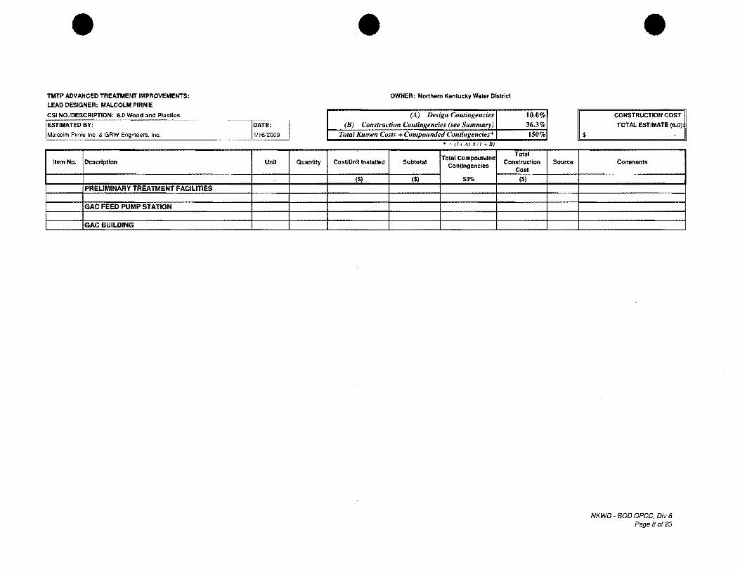
• TMTP ADVANCED TREATMENT IMPROVEMENTS:
LEAD DESIGNER: MALCOLM PIRNIE
CSI NO./DESCRIPTION: 6.0 Wood and Plastics
ESTIMATED BY:
Malcolm P~nie Inc. & GRW Engineers, Inc.
IlemNo. Description Unit Quantity
PRELIMINARY TREATMENT FACILmES
GAC FEED PUMP S1 ATION
GAC BUILDING
• OWNER: Northern Kentucky Water District
(A) Design Contingencies 10.0% (B) Construction Contingencies (see Summary) 3fi.3%
TotallVlOwn Costs + Compounded Contingencies· 150% • ~(!+A xtJ tB)
Total Compounded Total
Cost/Unit tnstalled Subtotat Construction Contingencies
Cost
($) ($) sew. ($)
$
Source
• CONSTRUCTION COST
TOTAL ESTIMATE (6.D)
Comments
NKWO BOO OPCC, Oiv 6 Page 80123

NORTHERN KENTUCKY WATER DISTRICT
Proiect
Case No. 2011-_ Exhibit _--.:...=---_
Tavlor Mill Treatment Plant Advanced Treatment Improvements
Kenton County 184-0457
Engineer's Opinion Of Probable
Construction Cost

Northern Kentucky Water District 2835 Crescent Springs Road • Erlanger. KY 410108
Taylor Mill Water Treatment Plant Advanced Treatment Improvements
1 00% Opinion of Probable Construction Cost
October 2010
4n5-012
Malcolm Plrnle, Inc. 8600 Governor's Hill Drive Suite 210
GRW, Inc. 801 Corporate Drive Lexington, KY 40503
COP Engineers Strand Associates, 3250 Blazer Parkway Inc. Lexington KY 40509 1525 Bull Lea Road, Ste 100
Cindnnatl, OH 45?49 Cincinnati, OH 4249
c •. ......... ~( cdpengineers sa aTIIIAND -eegry!f!!.!Nl.eNgINlle ...

I I
I
I
I
I
I
I
I
MALCOLM PIRNIE
Date:
To:
from:
October 5, 2010
Amy Kramer, P.E., NKWO
Jason M. Abbott, P.E.
Memorandum
Re: TMTP 100% Submittal Opinion of Probable Construction Costs
Project No.: NKWO Taylor Mill Advanced Treatment Improvements Project
An opinion of probable construction costs (OPCC) was developed for the 100% submittal based on the current design. The cost opinion was developed as a Class 1 estimate in accordance with AACE guidelines and has a predicted accuracy of -5% to +10%. This range of accuracy has "narrowed" throughout the project. The summary of the OPCC is shown below.
100% Submittal Opinion of Probable Construction Costs
Item Cost
Opinion of Probable Construction Cost $27,468,000
AACE Class 3 Estimate -5% Range $26.095,000
II. II.rr:- rl~~s 3 Estimate +10% Range I' - _lc;I.;;a $30,215.000
Many of the design variables have been addressed since the OPCC was first developed for the (BOD). Design Contingencies have been reduced to 0%, while markups and construction contingencies continue to be utilized in an attempt to account for any remaining unknowns associated with the construction.
The 100% submittal OPCC summary sheet, subsequent breakdowns of the costs by CSI Master format 1995 division, and the comparison of the 60% submittal and the 100% submittal OPCCs can be found attached to this memo. The summary sheet includes a markup of 20% for the contractor's indirect costs, which include bonds, mobilization, insurance, overhead and profit, and contingency. The contractor's indirect cost markup remains reduced by 5%, to 20% (originally 25% in the 30% OPCC) due to the current bidding climate. The 5.5% that was originally included to escalate the cost to the middle of the construction project (2012) based on 5.5% ENR annual increase in construction costs, has been reduced to 2.25% due to the current bidding climate. In total the OPCC includes a markup of 22.25% or approximately $6,112,000.
In the 60% Submittal, an OPCC of approximately $28,021,000 was estimated.
Since the 60% Submittal was compiled, additional items have been added to the project and other variables have been finalized, resulting in the change in cost between the 60% submittal OPCC and this 100% OPCC. The total change in cost is

I I I I I I I I I
october 5. 2010 Page 2 of 2
approximately $553.000. Divisions 4, 6, 7, 8. 9. 10, 11, 12. and 16 show a cost savings due mainly to the further understanding of the building design and removal of the design contingency. Summaries of the increases in cost. as broken down by Division follow:
• Div 1 (General Requirements) - The computer and Owner's contingency aliowance$117,OOO.
• Div 2 (Site Work) - Further understanding of the extent of storm water conveyance, detention pond, demolition an~ additional fencing and gates $331,000.
• Div 3 (Concrete) - Additional cost for generator and substation concrete pad $1,000.
• Div 5 (Metals) - Increased cost due to addition of elevated walkway panels and railings, and the generator stairs and landing $30.000.
• Div 13 (Special Construction) - Increased cost due to finalized instrumentation and controls costs for pH instrument; turbidity analyzer, PLC components and security equipment $109,000
• Div 14 (Conveying Systems) - Increased cost for EQ and GAC backwash pump removal systems (portable hoist and jib crane) $10,000.
• Div 15 (Mechanical) - Increased cost for dehumidification unit, air cooled condensing unit, HVAC control wiring, water lines, natural gas lines, temporary FI pipe, sump pumps, and additional valves and fittings $226,000.
cc: File: 4775-012 jma

100% SUBMITTAL
TMTP ADVANCED TREATMENT IMPROVEMENTS: Opinion Of Probable Construction Cost Estimate Summary
Division Description Total Construction Cost % of Total
1 General Requirements $ 240,000 0.9
2 Site Work $ 2,253,000 8.2
3 Concrete $ 2,615,000 9.5
4 Masonry $ 1,251,000 4.6
5 Metals $ 428,000 1.6
6 Wood and Plastics $ 11,000 0.0
7 Thermal and Moisture Protection $ 953,000 3.5
8 Doors and Windows $ 436,000 1.6
9 Finishes $ 337,000 1.2
10 Specialties $ 2,000 0.0
11 Equipment $ 7,850,000 28.6
12 Furnishing $ 36,000 0.1
13 Special Construction $ 413,000 1.5
14 Conveying Systems $ 93,000 0.3
15 Mechanical $ 3,542,000 12.9
16 Electrical $ 7,008,000 25.5
Opinion Of Probable Construction Cost $ 27,468,000 100.0
AACE Class 1 Estimate (-5%1 $ 26,095,000
I AACE Class 1 Estimate (+10%1 $ 30,215,000
t b . I d th ,,1/ t· t· Costs a ove me u e e 0 owmg cons rue Ion con mgeneles
Bonds 1.5%
I Mobilization 2.0%
Insurance 1.5%
Overhead & Profit 5.0%
Contingency 10.0%
Subtotal 20.0% I Escalation (2.25% of Direct and Indirect' 2.3%
Subtotal Indirect Cost 22.3%
Construction Contingencies' contribution to Total Construction Cost $ 6,112,000 I I
Note: All costs rounded up to the nearest $1,000.
I I I I
NKWD 100% SUBMITTAL OPCC, 1014/2010

NORTHERN KENTUCKY WATER DISTRICT
Project
Case No. 2011-Exhibit A
Tavlor Mill Treatment Plant Advanced Treatment Improvements
Kenton County l84-0457
Plans and Specifications prepared by Malcolm Pirnie, GRW, COP Engineers, and Strand Associates titled "Taylor Mill Treatment Plant Advanced Treatment
Improvements"

The following items are enclosed separately from this volume in hard copy and enclosed in this submittal in electronic copy.
• Plans prepared by Malcolm Pimie, GRW, CDP Engineers, and Strand Associates titled "Taylor Mill Treatment Plant Advanced Treatment Improvements" dated March 2011
• Specifications prepared by Malcolm Pimie, GRW, CDP Engineers, and Strand Associates titled "Taylor Mill Treatment Plant Advanced Treatment Improvements" dated March 2011
2835 Crescent Springs Rd Erlanger, KY 41018 (859) 578-9898 Fax (859) 578-5456

NORTHERN KENTUCKY WATER DISTRICT
Project
Case No. 2011-_ Exhibit B
Taylor Mill Treatment Plant Advanced Treatment Improvements
Kenton County 184-0457
CERTIFIED STATEMENTS
Affidavit
Franchises
Plan Review and Pennit Status
Easements and Right-of-Way Status
Construction Dates and Proposed Date In Service
Plant Retirements

AFFIDAVIT Taylor Mill Treatment Plant Advanced Treatment Improvements
Affiant, Jack Bragg, Jr., ,being the first duly sworn, deposes and says that he is the Vice President of Finance of the Northern Kentucky Water District, which he is the Applicant in the proceeding styled above; that he has read the foregoing "Taylor Mill Treatment Plant Advanced Treatment Improvements" Application and knows the contents thereof, and that the same is true of his own knowledge, except as to matters which are therein stated on information or belief, and that is to those matters he believes them to be true.
Vice President - Finance Northern Kentucky Water District
Subscribed and sworn to before me in said County to be his act and deed by Jack Bragg, Jr., Vice President of Finance of the Northern Kentucky Water District, this _--,q~. _day of /l,Al 2. J L 2011.
~. Kenton County, Kentucky My commission expires ..s /9/~~/l
~,
Northern6KentucJsy tr t Wqt~D!Llb
Franchises required - None
Plan Review and Permit Status - The District has reviewed and approved the plans and specifications prepared by Malcolm Pirnie, GRW, CDP Engineers, and Strand Associates titled "Taylor Mill Treatment Plant Advanced Treatment Improvements" dated March 2011.
The District received approval from the Division of Water on February 18,2011 (see attached letter).
Easements and Right-of-Wav Status - Easement and Right-of-Way statements are not required.
Start date of construction - October 2011
Proposed date in service - May 2014
Plant retirements - There are no retirements as a result of this project.
2835 Crescent Springs Rd Erlanger, KY 41018 (859) 578-9898 Fax (859) 578-5456

NORTHERN KENTUCKY WATER DISTRICT
Project
Case No. 2011-_ Exhibit B
Tavlor Mill Treatment Plant Advanced Treatment Improvements
Kenton County 184-0457
PLAN REVIEW AND PERMIT STATUS
Approval Lettcr from Kentucky Division of Water

\. ~ "-\ -~~-=t-C-DPO
STEVEN L. BESHEAR
GOVERNOR
ENERGY AND ENVIRONMENT CABINET
DEPARTMENT FOR ENVIRONMENTAL PROTECTION
DIVISION OF WATER
200 FAIR OAKS LANE, 4TH FLOOR
FRANKFORT, KENTUCKY 40601
www.kentucky.gov
February 18, 2011
LEONARD K. PETERS
SECRETARY
RECEIVED
FEB 2 3 2011
Amy Kramer, Engineering Manager NOlihern KY Water District
ENGINEERING DEPT.
2835 Crescent Springs Rd PO Box 18640 Erlanger, KY 41018
Dear Ms. Kramer:
RE: Nolthem KY Water District AI# 2485 APE20 1 00018 Taylor Mill WTP Advanced Treatment Improvemenls Kenton County, KY
We have reviewed the plans and specifications for the above referenced project. The plans include the following:
1. Construction of Preliminary Treatment/Granular Activated Carbon (GAC)
I
I
Building with rapid mix flocculation, Plate settling, residuals collection system and GAC pressure vessels.
3. Construction of a GAC Feed Pump Station. 4. Relocation of existing UV system 5. Installation of an electrical substation and two back-up generators; 6. Demolition of existing flocculation basins, sedimentation basins, and tunnel structure.
It has been detennined that the plans and specification are technically APPROVED with respect to the sanitary features of design as of this date with the following'stipulations:
A. The capacity of the treatment plant shall remain at 12 MGD (8,333 gpm).
B. Water pipe materials and adhesives used in the construction shall be NSF approved and compatible with various pH ranges and chemical to be used.
The following infonnation and requirements relate to the Drinking Water State Revolving Fund.
1. You are hereby authorized to advertise for bids to construct this project. In addition to other notices, you shall advertise the bid for seven (7) to tWenty-one (21) days prior to the Bid Opening date in the newspaper with the largest circulation in your area. Please provide the bid opening date to Cathy Arnett at the Division of Water who may be reached at (502) 564-3410.
KenruckyUnbridledSpirit.com An Equal Opportunity Employer MJFID

r'~ Taylor Mill WTP Advanced Treatment Improvements -PWSID # 0590220-10-018 February 18, 20 II Page 3 of3
14. This approval has been issued under the provisions of KRS chapter 224 and regulations promulgated thereto. Issuance of this approval does not relieve the applicant from the responsibility of obtaining any other penuits or licenses required by this and other state, federal, and local agencies.
If you have any questions concerning tbis project, please contact William Wright at (502) 564-3410 ext. 4829.
SVlD:WLW
Enclosures c: Jason Abbott, Malcolm Pil11ie
Kentucky Infrastructure Authority Cathy Al11ett, Division of Water Public Service Commission Division of Plumbing Florence Regional Office
Sincerely,
Solitha Dharman, PE Supervisor, Engineering Section Drinking Water Branch Division of Water

NORTHERN KENTUCKY WATER DISTRICT
Project
Case No. 2011-_ Exhibit C
Tavlor Mill Treatment Plant Advanced Treatment Improvements
Kenton County 184-0457
BID INFORMATION AND BOARD RESOLUTION
Bid Tabulation
Engineer's Recommendation of Award
Board Resolution
ITEMS CONCERNING BID INFORMATION AND BOARD RESOLUTION
The bid opening is set for May 3, 2011. The bid tabulation will be forwarded. )
The Engineer's Recommendation of Award will be forwarded.
- The Board Resolution for the May 19,2011 meeting will be forwarded.
Crescent Springs Rd Erlanger, KY 41018 (859) 578-9898 Fax (859) 578-5456

NORTHERN KENTUCKY WATER DISTRICT
Project
Case No. 2011-_ Exhibit ' C
Taylor Mill Treatment Plant Advanced Treatment Improvements
Kenton County 184-0457
Bid Tabulation

NORTHERN KENTUCKY WATER DISTRICT
Project
Case No. 2011-_ Exhibit C
Taylor Mill Treatment Plant Advanced Treatment Improvements
Kenton County 184-0457
Engineer's Recommendation of Award
NORTHERN KENTUCKY WATER DISTRICT
Project
Case No. 2011-_ Exhibit C
Tavlor Mill Treatment Plant Advanced Treatment Improvements
Kenton County 184-0457
Board Resolution

NORTHERN KENTUCKY WATER DISTRICT
Project
Case No. 2011-_ Exhibit D
Tavlor Mill Treatment Plant Advanced Treatment Improvements
Kenton County 184-0457
PROJECT FINANCE INFORMATION
Customers Added and Revenue Effect
Debt Issuance and Source of Debt
Additional Costs for Operating and Maintenance
USoA Plant Account
Depreciation Cost and Debt Service After Construction

Customers Added and Revenue Effect: There will be zero new customers added and no revenue effect as a result of the Taylor Mill Treatment Plant Advanced Treatment Improvements project.
Debt Issuance and Source of Debt: This project will be paid from the District's Five-Year Capital Budget, PSC No. 136 "TMTP Advanced Treatment and Sedimentation Basin Replacement & Generator" with a budget of $35,000,000 which includes construction cost, engineering, and contingencies. A summary of the project costs (prior to opening bids) is provided below:
o Design Engineering o Construction Engineering o Contractor's Bid o Misc. & Contingencies
Total Project Cost
$ 1,950,280 $ 1,150,000 $27,468,000 $ 4,431,720 $35,000,000
The Engineer's estimate presented in Exhibit A is $27,468,000 for construction. The construction contingency amount of $6,112,000 shown in the engineer's 100% Opinion of Probable Construction Cost covers contractor bonds, mobilization, insurance, overhead and profit, plus a contingency amount for items that may have been excluded from the quantity take-offs in the detailed estimate. The engineer's contingency also includes a factor for escalation to the mid-point of construction.
The District's $4,431,720 amount for miscellaneous costs and contingencies includes materials and equipment that the District will be purchasing directly to avoid the contractor's mark-up (i.e. SCADA computer hardware and software for process control) as well as repair of erosion in the hillside along Banklick Creek that, if left uncorrected, could be exacerbated by plant operations and future discharge of storm water from the detention pond that will be constructed with the Advanced Treatment project.
The project cost information will be reviewed following the Taylor Mill Treatment Plant Advanced Treatment Improvements bid opening and updated, if appropriate, for this application.
The project will be funded through multiple sources. The project is already partially funded through BAN 2009 in the amount of $1,833,000 for engineering services. It is proposed that the remaining $33,167,000 be taken from future Bond Anticipation Notes.
2835 Crescent Springs Rd Erlanger, KY 41018 (859) 578-9898 Fax (859) 578-5456

• Page2 April 8, 2011
USoA Accounts: The anticipated amounts for the project cost of $35,000,000 will fall under the following Unifonn System of Accounts Codes:
Code 304 "Structures and Improvements" Code 310 "Power Generation Equipment" Code 311 "Pumping Equipment" Code 320 "Water Treaunent Equipment"
$17,967,802 $ 7,029,820 $ 655,269 $ 9,347,109
Additional Costs and O&M: Additional operating and maintenance costs incurred for the project are as follows:
Power Labor Maintenance
$ 75,000 $ 70,000 $1,500,000 $ 1,645,000 Annual O&M
Depreciation and Debt Service: Annual depreciation and debt service after construction are as follows:
Depreciation: $479, 1411year over 37.5 years for Code 304 Structures & Improvements $351,491/year over 20 years for Code 310 Power Generation Equipment $32,763/year over 20 years for Code 311 Pumping Equipment $311,570/year over 30 years for Code 320 Water Treatment Equipment
Debt Service: $2,483,336 over 25 years (conventional 5.0% loan).

Fort Thomas Treatment Plant Advanced Treatment Proj~ct
-
---
I --.
Depreciation Annual DepreciCiltion Cost Years Depreciation
Account 304 Structures & Improvements $17,967,802 37.5 $479,141.39
Account 31 o power Generati~:m Equipment $7,029,820 20 $351~491.00 I
.Account 311 Pumping Equipment $655,269, 20 $32,763.45
Account 320 Water Treatmen~ Equipment $9,347,109 30 $311,570.30 !
Total $35,000,000.00 i $1,174,966.14 i
Debt Service on SRF Loan
Total Borrowed $0 -Interest Rate including admini~tration fee 2.20%i Term (Yearsl .. 20:
Annual Debt Service SRF $0.00 --.......
Debt service on bond issue ~
Total Borrowed $35,000,000 Interest Rate 5.00% Term (Years) 25
!
Annual Debt Service Traditional $2,483,336.01
Total Annual Debt Service $2,483,336.01 i

NORTHERN KENTUCKY WATER DISTRICT
Project
Case No. 2011-_ Exhibit E
Taylor Mill Treatment Plant Advanced Treatment Improvements
Kenton County 184-0457
PSC ANNUAL REPORT - 2010

Water
CLASSA& B
WATER DISTRICTS AND ASSOCIATIONS
ANNUAL REPORT
OF
RECEIVED MAR 80 2011
PUBLIC SERVICE COMMISSION
Northern Kentucky Water District
2835 Crescent Springs Road, Erlanger, Kentucky 41018
TO THE
PUBLIC SERVICE COMMISSION
OF THE
COMMONWEALTH OF KENTUCKY
211 SOWER BOULEVARD P. O. BOX 615
FRANKFORT, KENTUCKY 40602
FOR THE CALENDAR YEAR ENDED DECEMBER 31, 2010

Northern ,Kentuckv
WaterD~strJLct
Chllss ,& A & B"
Water Districts & Associations
ADIllD.uall Report
OF
NortHnern Kentucky Water Dnstrict
2835 Crescent SprDngs Road, P.O. Box 18640
IErlanger, KY 4]1018
1'0 tllne
PUBJLIC SIERVlIC.IE COMM1ISSION oftllne
CommonweaRtHn of Kentucky
For the caDen.d1ar Year lEnded: Decemb~r 31, 20]U)

Rev. 7-19-2004
KENTUCKY PUBLIC SERVICE COMMISSION REPORT OF GROSS OPERATING REVENUES DERIVED FROM INTRA-KENTUCKY
BUSINESS FOR THE YEAR ENDING DECEMBER 31, 2010
Post Office Box 18640 NORTHERN KENTUCKY WATER DISTRICT 2835 Crescent Springs Rd - Erlanger, Ky 41 018·0640 (Utility Reporting)
FEIN # (Federal Employer Indentification Number) 61·1311695
(DO NOT INCLUDE TAXES COLLECTED)
(1) Gross Revenues of Electric Utility... ... ... .... $ ____ _
(2) Gross Revenues of Gas Utility .................. $ ____ _
(3) Gross Revenues of Water Utility ............... $ 42,118,806
(4) Gross Revenues of Sewer Utility ............... $ ____ _
(5) Other Operating Revenues ............. .......... $ _---:1.J.:,6;..:1.;;;,9:.,:;,9.;;;,54.:,.
...... TOTAL GROSS REVENUES.... .•.. ........ $ 43,738,760
State of Kentucky ........ ) ) ss.
County Campbell ........ )
(Address)
Jack Bragg. CPA being duly sworn, states tha1 being duly sworn, states that he/she is
Vice-PresidentlCFO of the Northern Kentucky Water District that the above report of gross
revenues is exact accordance with Northern Kentucky water District. and that such
books accuraleley show the gross revenues of: Northern Kentucky Water District,derived from
Intra-Kentucky business for the calendar year ending December 31, 2010
This the 28th day of March, 2011
a,z~ ?otary r
~~ VP/CFO
State at Large County Commission Expires

Checklist for the Annual' 1rt/or C Ware Companies To be completed and reiUrned with the annual report
Page 1 of 2 Page No Account No • a5'" No y es N 0 If I' h no, expl am w y
4 to 6 The identification pages have been completed. X
7 101-106 agrees with 13 Total 101-106 X
7 108-110 agrees with 15 Total 301-348 Cols c & h X
7 114-115 agrees with 16 Net Blanace 1]4-115 X
7 123 agrees with 17 Total 123 X 7 124-125 agrees with 17 Total 124 & Total 125 X
7 126 agrees with 17 Total 126 X
7 127 agrees with 17 Total 127 X
7 141-144 agrees with 18 Net Balance 141-144 X
7 151-153 agrees with 19 Total 151-153 X ..
7 162 agrees with 19 Total 162 X
8 181 agrees with 20 Total 181 X
8 182 agrees with 21 Total 182 X
8 186 agrees with 20 Total 186 X
9 214 agrees with 12 Total 214 X
9 215.1 agrees with 12 Tolal215.l X
9 215.2 agrees with 12 Total 215.2 X
9 221 agrees with 23 Total Col4 X
9 221 agrees with 23 Total Col 12 X
9 224 agrees with 22 Total Col f X
9 232 agrees with 24 Total 232 X
9 223 agrees with 24 Total 233 X
9 234 agrees with 24 Total 234 X
9 236 agrees with 25 Beginning & Ending Balance 236 X
9 237 agrees with 25 Total 237 Cols b & e X
9 242 agrees with 26 Total 242 X
9 251 agrees with 20 Total 251 X
9 252 agrees with 21 Beginning & Ending Balance 252 X

Checklist for the Annual ,Jrtfor C Ware Companies To be completed and reiuined with the annual report
Page 2 of 2
Pa~eNo. Account No. Page No. Yes No If no, explain why
IO 400 agrees with 27 Total Water Operating Revenue Col e X
10 401 agrees with 28 Total 601-675, Col c X
10 408.1&408.2 agrees with 25 Total Taxes Accrued 408-10-408.20 X
11 421 agrees with 25 Total Interest Accrued Col c X
II Net Income Before Contribution agrees with 12 Balance Trans Inc Col c X
13 101 agrees with 14 Total Water Plant Col f X
14 The analysis of water utility plant acounts eols c throuh k has been Completed X
15 The analysis of accumulated depreciation & amortization by primary accounts X nas oeen complereo
20 186.1 agrees with 26 Total 186.1 Col c X
22 Schedule of Long-Term Debt has been completed X
23 Schedule offiond Maturities has been completed X
21 Taxes collected (example: school tax, sales tax, granchise tax) have been X excluded from Revenue and Expenses
27 The analysis of water operating revenue Cols c,d, and e has been completed X
28 The analysis of water utiltiy expense Cols c through k has been complete X
29 Schedule of Pumping and Purchased Water Statistics has been completed X
29 Total Col (d) agrees with 30 Line 4, Total Production & Purchased X
29 Total Col (e) agrees with 30 Line 13, Total Water Sales X
30 466 Total Gals agrees with 30 Line 11, Sales for Resale (466) ~ Oath page has been completed X

PUBLIC SERVICE COMMISSION OF KENTUCKY
PRINCIPAL PAYMENT AND INTEREST INFORMATION
FOR THE YEAR ENDING DECEMBER 31,2010
1. Amount of Principle Payment during calender year $ 6,956,736.11
2. Is Principal Current? Yes X No
3, Is Interest Current? Yes X --~--
No
4. Has afllong-term debt been approved by the Public Service Commission?
Yes X No PSC Case No _____ _
SERVICES PERFORMED BY
INDEPENDENT CERTIFIED PUBLIC ACCOUNTANT ("CPA")
Are your financial statement examined by a Certified Public Accountant?
Yes X No
If yes, which service is performed?
Audit x
Compilation _______ _
Review
Please enclose a copy of the accountant's report with the annual report

ADDITIONAL REQUESTED INFORMATION
Utility Name Norther Kentucky Water District
Contact Person ...;.J,;:.;..ac,,-k,,-B,,-r~agli!.Ogi!..:..' ..;..J;..:..r, ..;;:.C~P,,-A~ ____________ _
PLEASE COMPLETE THE ABOVE INFORMATION, IF IT IS AVAILABLE.
IF THERE ARE MULTIPLE STAFf WHO MAY BE CONTRACTS PLEASE INCLUDE ·rHEIR NAMES AND E-MAIL ADDRESS ALSO.

Additionallnfonnation Required by Commission Orders
Provide any special information required by prior Commission orders, as well as any narrative explanations necessary to fully explain the data. Examples of the types of special information that may be required by Commission orders indude surchage amounts, collected, refunds issued, and unusual debt requirments.
Case # Date of Item/Explanation Order
96-234 8126/1996 Merger of Campbell Co. Ky. Water District and Kenton Co. Water District No.1. Effective date of Merger 1/1/1997
97-3 9121/1997 Defeasance of the former Campbell Co. Ky. Water District Bonds Principal of the issue $9,630,000
92-482 311411992 SubDistrict A a. Number of Customers as of 12-31-2010 586 b. Total Surcharge billed during 2010 $61,018 c. Accumulated surcharge billed. $1,318.817 d. Remaining Debt Service on debt which NKWD Issued to Finance Facilities $465,733
94-409 1/2611995 SubDistrict B a. Number of Customers as of 12-31-2010 292 b. Total Surcharge billed during 2010 $62.972 c. Accumulated surcharge billed. $841,517 d. Remaining Debt Service on debt which NKWD Issued to Finance Facilities $1.355.829
95-582 2/811996 SubDistrict R a. Number of Customers as of 12-31-2010 236 b. Total Surcharge billed during 2010 $52,070 c. Accumulated surcharge billed. $3.259,814 d. Remaining Debt Service on debt which NKWD Issued to Finance Facilities $6,304,142
95-582 2/8/1996 SubDistrict RL a. Number of Customers as of 12-31-2010 87 b. Total Surcharge billed during 2010 $38.239 c. Accumulated surcharge billed. $583,440 d. Remaining Debt Service on debt which NKWD Issued to Finance Facilities $2,776.943
97-468 9/411998 Per Item 7 on the order. See attached exhibit ML 1
2000-329 7121/2000 SubDistrict C a. Number of Customers as of 12-31-2010 992 b. Total Surcharge billed during 2010 $221.948 c. Accumulated surcharge billed. $1,809,581 d. Remaining Debt Service on debt which NKWD Issued to Finance Facilities $5,201,932
2000-171 5/512000 SubDistrict D a. Number of Customers as of 12-31-2010 154 b. Total Surcharge billed during 2010 $55,648 C. Accumulated surcharge billed. $389,051 d. Remaining Debt Service on debt which NKWD Issued to Finance Facilities $1,162,245 e. Bond issued 2001, Payback $1,529,229.74 (25years), rate variable
2001-198 6127/2001 Defeasance of the former Kenton County Water District No.1 Bonds - Principle Issue $45,448,000
2002-00363 10/1/2002 Defeasance of the former Klenton County Water District No.1 Bonds $10,575,000
2002-00468 3/112003 Defeasance of 1995C Bonds with Issuance of 2003A Bonds $1,615,000
2002-00105 413012003 Water Rate Increase

Additional Information Required by Commission Orders· Contiuned
2002-00105 61112003 Issue of 2003 B Bonds $30,270,000
2003-00167 7/1812003 SubDistrict E a. Number of Customers as of 12-31-2010 183 b. Total Surcharge billed during 2010 $66,988.00 c. Accumulated surcharge billed. $360,428.39 d. Remaining Debt Service on debt which NKWD Issued to Finance Facilities $1,497,875.71 e. Bond issued 2004, payback $1,859,684.55 (25years), rate variable
2003-00191 7/18/2003 SubDistrict RF a. Number of Customers as of 12-31-2010 33 b. Total Surcharge billed during 2010 $8,621 c. Accumulated surcharge billed. $62,255 d. Remaining Debt Service on debt which NKWD Issued to Finance Facilities $162,466
2003-00224 6/1412004 Issue of 2004A Bonds $10,455,000
2003-00224 6/1412004 SubDistrict K a. Number of Customers as of 12-31-2010 51 b. Total Surcharge billed during 2010 $8,245 c. Accumulated surcharge billed. $44,241 d. Remaining Debt Service on debt which NKWD Issued to Finance Facilities $177,739 e. Bond issued 2004, payback $208;824.68, (25years), rate variable
2003-00404 121212003 Defeasance of 1993, 1195A and 1995B Bonds with Issuance of 2003C Bonds $23,790,000
2005-00148 412812006 Water Rate Increase & Bond Issuance $29,000,000
2006-00315 1212612007 SubDistrict F a. Number of Customers as of 12-31-2010 39 b. Total Surcharge billed during 2010 $11.591 c. Accumulated surcharge billed. $24.973 d. Remaining Debt Service on debt which NKWD Issued to Finance Facilities $396,426 e. Bond issued 2007, payback $415,102.00 (25years), rate vanable
2007-00131 6/27/2007 SubDistrict G a. Number of Customers as of 12-31-2010 88 b. Total Surcharge billed during 2010 $28,148 c. Accumulated srucharge billed, $55,538 d. Remaining Debt Service on debt which NKWD Issued to Finance Facilities $1,001,425 e. Bond issued 2007, payback $1,042,078.00 (25years), rate variable
2007-00135 12/21/2007 Water Rate Increase & Bond Issuance $30,075.125
2010-00049 11712011 Water Rate Increase & Bond Issuance $32,500,000

MAJOR WATER PROJECTS
Instructions: Provide details about each major water project which is planned but has not yet been submitted for approval to the Public Service Commission. For the limited purposed of this report a "Major Project" is defined as one which is not in the ordinary course of business, and which will increase your current utility plant by at least 20%
Brief Project Description (improvement, replacement, building construction, expansion. If expansion. provide the estimated number of new customers):
N/A
Projected Costs and Funding Sources/Amounts:
Approval Status: (Application for financial assistance filed, but not approved; or application approved, but have not advertised for construction bids)
Location: (coummunity, area or nearby roads)

TABLE OF CONTENTS
FINANCIAL SECTION
Identification ,,' ", ". ,., .... " " ... , """'" ."." '" ", , .. ".,,' , ..... ' ... " ,., , ... """" " ... '"'''''' " ........ " ......... , ..... ..
Comparative Balance Sheet· Assets And Other Debits .. , .......... " .......................... , ... , ... ,' ,.' , ...... ,., , .. ,
Comparative Balance Sheet - Equity Capital & UabHities ................. ,." .. " ... ,'" ". ", ...... " ........ " ..... , .. ,
Comparative Operating Statement ",."." ... ,"'''''''''''''''' ....... ".". " ...... ,.: ......... '" ", .. , ..... "" ,,,.,.,, "' .. "
Statement of Retained Eamings ... " .......... " ....... ................... " .......... " .. ".,." ...... ". "." ...... , ....... " '"
Utility Plant ............. " " .......... , ...... " .. , .... " '" ... " ................................... " ", .. , " , .. , ..... , " .. " " . " ... , , ..
Accumulated Depreciation ............ , ...................... , ......... "' .. ' '" ,,, .... ,, ....... ,, .... " .... " ......... ", , .... , .. ,.,'
Water Utility Plant Accounts '" ", , .......... , .. , .... " ... ". " ........ " ", ........ , ... ". " ..... ", .. ". , .. ".,,, ........ , ...... ..
Analysis of Accumulated Depreciation by Primary Account ........ , , .. """ ...... '" ."., ..... , .................. , , .... ,.
Accumulated Amortization ". '" " ... , "." .. " '" '" , ..... , ..... , .. , .... , .. ,." ... " .. " ... '" ,', '" ", ". ," , .. " .... '" "''', ,,,.
Utility Plant Acquisition Adjustments ..... , .,." ... , .,. ,., , .. ,., .. , .... , .. , ... ,., .............. ,. , ........ '" ..... , .... , .. , .... , ..
Investments and Special Funds : ..... ". " .......... " ........... " ............ , .. " .... " " ..... ".".,,", ... "." .. " "' .. , .. ..
Accounts and Notes Receivable - Net ." ......... , ......... , ................. " .. , ..... ' .... " , ...... , .. " " .... " .. " .......... .
Materials and Supplies " ....... ", '" " ........ " " ... , .... ' .. " "' .. , ..... , ". " ......... ,."." ... , ... " ... " .... , .. ,,, '" , .. '" , ..
Prepayments """ .. , '" '" '" ", ", '" ", ,,,.,, , .. ,., ... ". " ....... , ..... " .. " ...... ". '" " ... , " ... ' " ........... '" ,,, ... " ... ..
Miscellaneous Deferred Debits ...... ," , ..... ,,, ....... ,, '" , .. " .. " ".". '" ", .... " '" " ....... ". " .. " ". ' ...... , ....... " ... .
Unamortized Debt Discount and Expense and Premium On Debt ." .. ,,, ........ ,, ., .. " ........................... ".
Extraordinary Property Losses ..... , .... " ' ....... , , ....... ,. "" ... ' ........................... ". , .. , ....... , .......... " ...... ..
Advances For Construction ............................................... ,' " ......................... ,., ............... ' ........ .
Long Term Debt ....... " " ................... , ................ ' , .. '" ,,, ........................................................ , ..... .
Bonds and Maturities ........................................................ ' ......... " .......... " ............................ ". "
Notes Payable .................................................. , .... "." ..................... " ............. " ............... , ... " ...
Accounts Payable To Associated Co, ............ ", .. , .................. " ....... '" "' ..... , , ........ , ...................... , ..
Accrued Taxes ................................................. " "., .. '" '" " ............ , ....................... ' " ... "" .'. " ... , ..
Accrued Interest .......... " ............. " .... " ..... , ,,, ..................... " ................ " ...... ' .... ", ... ". " ........ "" .. .
Mise, Current & Accrued liabilities ......... " .... , ........................... " "'''' , ........... " ........ , .................. ..
Regulatory Commission Expense .. .............................. ", .................... , ... ' ...................... , ... , " ... ..
WATER OPERATING SECTION
Water Operating Revenue .... " ................... "" " ... , ...... " .... " ............ ,." .......... "." ... " .................... .
Page
6-Apr
7-8
9
10-11
12
13
13
14
15
16
16
17
18
19
19
20
20
21
21
22
23
24
24
25
25
26
26
27
Water utility Expense Accounts "", .. , .. ,' ", ." , ... , ...... , ., ...... ,., .. ,', ... ,. ,., .,. ". '" ' ... , .... , ....... , .,. , ... , .. , ... , .. , 28
Pumping & Purchased Water Statistics ....................................... ' .... ' .... "...... ............................. 29
- 3"

HISTORY
I. Exact name of utility making this report. (Use the words: «The, Company, Incorporated or Incorporated" only when a part of the corporate name.)
Nortbern Kentucky Water District
2. Give location including city, street and number, of the executive office:
2835 Crescent Springs Road P.O. Box 18640 Erlanger, Kentucky 41018-0640
3. Give the location, including street, street number, and telephone number of the principle office in Kentucky:
Same as tf1.
4. Date of organization:
January 1, 1997
5. If a consolidated or merged entity, name all the previously separate entities.
Kenton County Water District Campbell County Water District
6. Date of each consolidation and each merger·
January 1, 1997
·4·

7. State whether the respondent is a water district or association.
Water District under Cbapter 74 - KRS
8. Name all operating departments other than water.
None
9. Name of counties in which you furnish water service.
Kenton, Campbell, & Boone
10. Give the number of employees:.
Full Time: 148 Part Time: 18
-5-

R~-"t:t of: F\, ear Ended: Location where books and records are located:
Name Title
Send correspondence to: Jack Bragg VP of Finance
Report prepared by: Jack Bragg VP of Finance
Northern Kentucky Water District 12/31/2010 2835 Crescent Springs Road, Erlanger, Ky 41018
Contacts: Salary
Principal Business Address Cbarged Utility
2835 Crescent Springs Road P.O. Box 41018-0640 Erlanger, Kentucky 41018 xxxxxxxxx
Same as above xxxxxxxxx
Officers and Managers
Drew Collins Chairperson Same as above 6,000.00 DClllg Wagner Vice Chairperson Same as above 6,000.00 r- .
6,000.00 J ' [Jester Treasurer Same as above r--~ . Dr. Pat Sommerkarnp Commissioner Same as above 6,000.00 Frank Jackson Commissioner Same as above 6,000.00 Fred Macke Secretary Same as above 6,000.00
C. Ronald Lovan President/CEO Same as above xxxxxxxxx
G;r/rem:SS:Page6 - 6-
Current Term
Expires
xxxxx
xxxxx
8/2612012 8/28/2011 8/26/2013 8/2112013 8/2812011 7/26/2012
xxxxx
-

COMPARATIVE BALANCE SHEET - ASSETS AND OTHER DEBITS
Account 2010 Ref. Previous No. Account Name Page ~ Year Current Year (a) (b) © Cd) (e)
UTILITY PLANT
101-106 Utility Plant 13 $ 347,503,188 $ 369,386,212 I
108-110 Less: Accumulated Depreciation and Amortization 13,15-16 (74,669,512) (82,113,459)
Net Plant $ 272,833,676 $ 287,272,753 114-115 Utility Plant Acquisition
Adjustments (Net) 16 3,464, III 3,262,991 116 Other Utility Plant Adjustments
Total Net Utility Plant $ 276,297,787 $ 290,535,744 OTHER PROPERTY & INVESTMENTS
121 Nonutility Property $ $ 122 Less: Accumulated Depreciation
and Amortization Net Nonutility Property $ $
123 Investment in Asso. Companies 17 124 Utility Investments 17 36,962,649 33,323,505 125 Other Investments 17 1,997,887 1,601,840
126-127 Special Funds 17
Total Other Property & Investments $ 38,960,536 $ 34,925,345
CURRENT AND ACCRUED ASSETS
131 Cash $ 12,973,478 $ 11,835,530 132 Special Deposits 133 Other Special Deposits 27,917,544 21,540,563 134 Working Funds 135 Temporary Cash Investments
141-144 Accounts Receivable, Less Accumulated Provision for Uncollectible Accounts 18 4,753,541 5,238,301
145 Accounts Receivable from Associated Companies
146 Notes Receivable from Associated Companies
151-153 Materials & Supplies 19 1,251,889 1,343,411 161 Stores Expense 162 Prepayments 19 152,269 442,448 171 Accrued Interest & Dividends
Receivable 172 Rents Receivable 173 Accrued Utility Revenues 4,700,000 5,400,000 174 Misc. Current & Accrued Assets
Total Current & Accrued Assets $ 51,748,721 $ 45,800,253

COMPARATIVE BALANCE SHEET - ASSETS AND OTHER DEBITS (CONT'D)
Account 2010 Ref. Previous No. Account Name Page Year Current Year (a) (b) c (d) (e)
DEFERRED DEBITS
181 Unamortized Debt Discount & Expense 20 $ 3,395,826 $ 3,044,809 182 Extraordinary Property losses 21 183 Preliminary Survey & Investagation
Charges 184 Clearing Accounts 185 Temporary Facilities 186 Misc. Deferred Debits 20 5,093,174 4,546,120 187 Research & Development Expenditures
Total Deferred Debits $ 8,489,000 $ 7,590,929
TOTAL ASSETS AND OTHER DEBITS $ 375,496,044 $ 378,852,271
-8-

COMPARATIVE BALANCE SHEET - EQUITY CAPITAL AND LIABILITIES
Account 2010 Ref. Previous No. Account Name Page Year Current Year (a) (b) c (d) (e)
Equity Capital
214 Appropriated Retained Earnings 12 $ 53,566,481 $ 43,992,811 215.1 Retained Earnings from Income
Before Contributions 12 $ 24,856,196 $ 38,299,847 215.2 Donated Capital 12 $ 61,121,735 $ 62,190,539
Total Equity Capital $ 139,544,412 $ 144,483,197
LONG-TERi~1 DEBT
221 Bonds 23 $ 185,065,000 $ 178,439,000 222 Reacquired Bonds 223 Advances from Asso. Companies 224 Other Long-Term Debt 22 12,289,068 17,451,799
Total Long-Term Debt $ 197,354,068 $ 195,890,799
CURRENT & ACCRUED LIABILITIES
231 Accounts Payable $ 3,789,037 $ 3,706,678 232 Notes Payable 24 29,260,000 29,260,000 233 Acts. Payable to Asso. Co. 24
8,0061 234 Notes Payable to Asso. Co. 24 235 Customer Deposits 13,4l3 236 Accrued Taxes 25 I 237 Accrued Interest 25 3,579,652 3,492,903 239 Matured Long-Term Debt 240 Matured Interest 241 Tax Collections Payable 242 Misc. Current & Accrued Liabilities 26 1,916,224 1,976,378
Total ClUTent & Accrued Liabilities $ 38,558,326 $ 38,443,965
DEFERRED CREDITS
251 Unamortized Premium on Debt 20 $ 39,238 $ 34,310 252 Advances for Construction 21 253 Other Deferred Credits
Total Deferred Credits 39,238 34,310
OPERATING RESERVES
Accumulated Provision for: 261 Property Insurance $ $ 262 Injuries & Damages 263 Pensions & Benefits 265 Miscellaneous Operating Reserves
Total Operating Reserves $ $
TOTAL EQUITY CAPITAL & LIABILITIES I $ 375,496,044 $ 378,852,271 i
-9-

COMPARATIVE OPERATING STATEMENT
Acct Ref. Previous No. Account Name Page Year Current Year (a) (b) c (d) (el
Utility Operating Income
Operating Revenues 27 $ 41,046,714 $ 43,738,760
401 Operating Expenses 28 $ 23,563,528 23,154,089 403 Depreciation Expenses 8,023,443 8,487,677 406 Amortization of Utility Plant
Acquisition Adjustment 201,120 201,120 407 Amortization Expense 378,962 378,962
408.1 Taxes Other Than Income 25 600,166 597,489
Utility Operating Expenses $ 32,767,219 $ 32,819,337
Utility Operating Income $ 8,279,495 10,919,423
413 Income From Utility Plant Leased to Others
414 Gains (Losses) From Disposition of Utility Property 9,069 -
Total Utility Operating Income $ 8,288,564 $ 10,919,423
Other Income and Deductions
415 Revenues From Merchandising, Jobbing and Contract Deductions $ $
416 Costs and Expenses of Merchandising, Jobbing and Contract Work
419 Interest & Dividend Income 638,601 955,195 420 Allowance for Funds Used During
Construciton 421 Nonutility Income (229,112) (144,026)1 426 Miscellaneous Nonutility Expense
Total Other Income & Deductions $ 409,489 8 11,169
TAXES APPLICABLE TO OTHER INCOME
408.2 Taxes Other Than Income $ $ I
Total Taxes Applic. To Other Income $ $
-10-
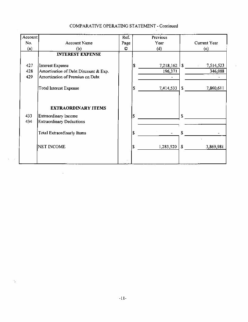
COMP ARA TIVE OPERATING STATEMENT - Continued
Account Ref. Previous No. Account N arne Page Year Current Year (a) (b) © (d) (e)
INTEREST EXPENSE
427 Interest Expense $ 7,218,162 $ 7,514,523 428 Amortization of Debt Discount & Exp. 196,371 346,088 429 Amortization of Premiun on Debt - -
Total Interest Expense $ 7,414,533 $ 7,860,611
EXTRAORDINARY ITEMS
433 Extraordinary Income $ $ 434 Extraordinary Deductions
Total Extraordinarly Items $ - $ -
NET INCOME $ 1,283,520 $ 3,869,981
-11-

Statement of Retained Earnings
~T. 2010 Amount
(a) (b) (c)
214 Appropriated Retained Earnings (state balance and purpose of each appropriated amount at year end):
Bond Proceeds $ 21.540.563 Debt Service and Reserve $ 15.577,413 ImErovement, Re~a;r and Re~Jacement $ 6,874,835
Total Appropriated Retained Earnings. '. " ... , ....... , .. , ...... , ......... $ 43.992.811
215.1 Retained Earnings From Income Before Contributions:
Balance Beginning of Year. .................. .......................... ... ...... , .... $ 24.856.196
435 Balance Transferred from Net Income Before Contributions ..................... $ 3,869,981
Other Changes to Account: 436 Appropriations of Retained Earnings .. , ................. , ...... , .. , . ~ ...... $ 9,573,670 439 Adjustments to Retained Earnings (requires Commission approval
prior to use): Credits (explain) $ Debits (explain) $
Balance End of year .......................... , ...................... , .................... $ 38,299,847
215.2 Donated Capital: Tapping
Fees Grants Other Total
Balance Beginning of year ....................... 8,100,610 21,781,761 31,239,364 61,121 735
Credits:
432 Proceeds from capital contributions ....... ,.,. 340,794 728,010 - 1,068,804
Other Credits (explain)
Debits: (explain - Requires Commission Approval)
Balance End of Year ................................ 8,441,404 22,509,771 31,239.364 62,190,539
-12-

NET UTILITY PLANT (ACCTS. 101 - 106)
Account No. Plant Accounts Total
101 Utility Plant in Service $ 331,504,524 102 Utility Plant Leased to Others 103 Property Held for Future Use 104 Utility Plant Purchased of Sold 105 Construction Work in Progress 37,881,688 106 Completed Construction Not Classified
Total Utility Plant $ 369,386,212
ACCUMULATED DEPRECIATION (ACCT.I08)
Description Total
Balance first of year $ 73,956,257
Credit during year: Accruals Charged to Account 108.1 8,487,677 Accruals Charged to Account 108.2 Accruals Charged to Account 108.3 Accruals Charged to Other Accounts (specify)
Salvage Other Credits (specify)
Total Credits $ 8,487,677
Debits during year: Book Cost of Plant Retired $ 330,475 Cost of Removal Other Debits (specify)
Total Debits $ 330,475 Balance end of year $ 82,113,459
-13-

WATER UTILITY'.-...ANT ACCOUNTS
.1 .2 .3 .4 .5
2010 End of End of IntangibJe SOS& Water Trans & Acct Previous CUrrent Plant Pumping Treatment Distrib General No. Account Name Year Additions Retirement Year Intan- Plant Plant Plant Plant (a) (b) (cl Cd) Ce) (f) (g) (h) (i) (j) (k)
301 Organization $XXXXXXX $XXXXXXX $XXXXXXX $XXXXXXX 302 Franchises $XXXXXXX $XXXXXXX $XXXXXXX $XXXXXXX 303 Land & Land Rights $3,187,998 $3,187,998 $XXXXXXX $29,200 $368,719 $190,530 $2,599,548 304 Structures & Improvements $82,179,522 $2,086,781 $84,266,303 $XXXXXXX $16,826,206 $45,528,293 $9,505,387 $12,406,415 305 Collecting & Impounding Reserviors $XXXXXXX
306 Lake, River & Other Intakes $1,463,171 $1,463,171 $XXXXXXX $1,463,171
307 Wells and Springs $XXXXXXX
308 Infiltration Galleries & Tunnels 309 Supply Mains $2,865,693 $2,865,693 $XXXXXXX $2,865,693
310 PQ'Ner Generation Equipment $1,406,079 $2,085,443 $3,491,522 $XXXXXXX $3,491,522
311 Pumping Equipment $10,753,024 $423,431 $2,158 $11,174,297 $XXXXXXX $4,On,127 $1,004,067 $6,093,104
320 Water Treatment Equipment $11,975,815 $393,937 $16,174 $12,353,578 $XXXXXXX $12.353,578
330 Distribution Reserviors & Standpipes $9,643,680 $9,643,680 $XXXXXXX $9,643,680
331 TransmisSion & Distribution Mains $135,140,109 $3,190,915 $688,616 $137 ,642~ $XXXXXXX $137,642,408
333 Services $23,529,305 $537,970 $159,375 $23,907, $XXXXXXX $23,907,900
334 Meters & Meter Installations $8,562,362 I $7,956,448 $201,489 $16,317,321 $XXXXXXX $16,317,321
335 Hydrants $6,610,261 $246,884 $51,750 $6,807,395 $XXXXXXX $6,807,396
336 Backflow Prevention Devices $XXXXXXX
339 Other Plant & Misc_ Equipment $3,429,360 $71 $3,429,290 $3,429,289
340 Office Furniture & Equipment $3,164,607 $320,246 $42,221 $3,442,634 $XXXXXXX $3,442,634
341 Transportation Equipment $2,830,447 $267,648 $194,346 $2,903,749 $XXXXXXX $2,903,749
342 Stores Equipment $276,873 $276,873 $XXXXXXX $276,873
343 Tools, Shop, & Garage Equipment $203,571 $64,676 $268.247 $XXXXXXX $268,247
344 Laboratory Equipment $112,308 $31,424 $143,732 $XXXXXXX $143,732
345 PQ'Ner Operated Equipment $864,721 $129,383 $69,664 $924,440 $XXXXXXX $924,440
346 Communication Equipment $330,360 $6,071.660 $5,427 $6,396,592 $XXXXXXX $6,396,593
347 Miscellaneous Equipment $597,702 $597,702 $XXXXXXX $597,702
348 Other Tangible Plant $XXXXXXX
Total Water Plant $309,126,968 $23,808,847 $1,431,291 $331,504,524 o $34,905,077 $62,746,179 $203,893,335 $29,959,933
- 14 -

Analysis of Accumulated Depreciation and Amori . ''In by Primary Account
- 2010 Balance Credits Durioo the ~, .;aT Year Balance Em .. -
j£ Beginning of Charges to Other Plant Other of Year
Account Year Dep. Exp. Credits Retirements Charges (b) c (d) (e) (f) (g) (h)
301 iOrganization 1$ $ $ $ 1$ $ 302 Franchises 303 Limited Term Interest in Land
and Land Rights 304 Structures & Improvements 20,756,008 2,583,553 23,339561 305 Collecting & Impounding
Reservoirs 306 Lake River & Other Intakes 869145 27568 896,713 307 Wells & Srpings 309 Supply Mains 530,077
~ 588,543
310 Power Generating Equip. 18,748 75,819 311 PumPing &luioment
~ 518,900 mm 6,087,192
320 Water Treatment &luip. 426,262 4986039 330 Distribution Reservoirs &
Standpipes 3,530,627 306267 3,836894 331 Transmissions & Distribution
Mains 17.778.014 2,377,572 20,155587 333 Services 7,857,888 591,050 8448938 334 Meters &. Meter Installations 2,119,687 470667 847 2589,507
335 Hydrants 1,516,863 177,455 1,694,317 339 Other Plant &. Misc. Equip. 2667,216 271,022 72 2938,166
340 Office Furniture & Equip. 1 915655 267,632 42,186 2,141,101 341 Transportation Equipment 2,300,700 244,407 194346 2,350761 342 Service Equipment 343 Tools Shop &. Garage &luip. 362,749 26057
B 344 Shop &luiornent 69794 12,694 345 Power Operated Equip. 660,360 illm 69,662 346 Telecommunications Equioment 262.867 5,427 (1)'
347 SCADA 348 Other Tangible Plant 593,856 534 594,391
Totals $ 73,956257 $ 8,487,676 $ - $ 330.475 $ (l $ 82.113.459
- 15 -

ACCUMULATED AMORTIZATION (ACCT. 110)
Description Total
Balance first of year .............................................. $ N/A Credit during year:
Accruals Charged to Account 110.1 ... $ Accruals Charged to Account 110.2 ... Other Accruals (specify)
Total Credits .................................................. $
Debits during year: Book Cost of Plant Retired ................... $ Other Debits (specify)
Total Debits .................................................. $
Balance end of year .............................................. $
UTILITY PLANT ACQUISITION ADJUSTMENT (ACCTS. 114 - 115) Report each acquisition adjustment and related accumulated amortization separately. For any acquisition adjustment approved by the Commission, include the Order Number.
ACCOUNT NAME TOTAL
Acquisition Adjustments (114) Original District 9-14-55 $ 263,366 District # 2 & 3 12-31-73 18,712 Mentor District 9-1-76 10,741 City of Cold Spring 228,253 City of Silver Grove 24,853 Newport Water Works 4,970,211
iTotal Plant Acquisition Adjustments .......................... $ 5,516,136
Accumulated Amortization (115) Original District 9-14-55 $ 263,366 District#2 & 3 12-31-73 I 18,712 Mentor District 9-1-76 10,741 City of Cold Spring 228,253 City of Silver Grove 24,853 Newport Water Works 1,707,220
Total Accumulated Amortization ............................ , $ 2,253,145
Net Acquisition Adjustments ................................... $ 3,262,991
-16-
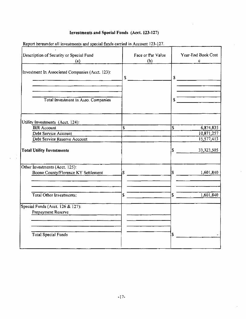
Investments and Special Funds (Acct. 123-127)
R h d II" eport ereun er a mvestments an d . I fu d . d' 3 1 specla n s carne In Account 12 - 27. ,
Description of Security or Special Fund Face or Par Value Year-End Book Cost (a) (b) c
Investment In Associated Companies (Acct. 123): $ $
Total Investment in Asso. Companies $
Utility Investments (Acct. 124): IRRAccount $ $ 6,874,835 Debt Service Account 10,871,257 Debt Service Reserve Account 15,577,413
Total Utility Investments $ 33,323,505
Other Investments (Acct. 125): Boone CountylFlorence KY Settlement $ $ 1,601,840
Total Other Investments: $ $ 1,601,840
Special Funds (Acct. 126 & 127): Prepayment Reserve
Total Special Funds $ -
-17-

ACCOUNTS AND NOTES RECEIVABLE - NET (ACCOUNTS 141 - 144)
Report hereunder all accounts and notes receivable included in Accounts 141,142,and 144. Amounts included in Accounts 142 and 144 should be listed individually.
Description
ACCOUNTS & NOTES RECEIVABLE: Customer Accounts Receivable (Acct. 141) .................. . .. , ...... ~ .. , ........... $ Other Accounts Receivable (Acct. 142)
Assessments $ 92,634 Other 47,853
Notes Receivable (Acct. 144) $
Total Accounts and Notes Receivable ...... '" ............................................... $
Accumulated Provision for Uncollectable Accounts (Acct. 143)
Balance first of year $ -Add: Provision for uncollectables for
current year. .................................................. $ Collections fo accounts previously written off ...................................................... Utility accounts ......................... . .. . ....... ~ ~ , ........ Others., .......................... , .............................
Total Additions ....................................................... $ Deduct accounts written off during year:
Utility Accounts .... " .................... , ............. , ...... $ Other ................................................... ..... ...
Total accounts written off ......................................... $ Balance end of year .......................... , ...................... , ............................ $
Total Accounts and Notes Receivable $
-18-
Total
5,097,814
140,487
5,238,301
-
5,238,301

Materials and Supplies (151 - 153)
Account N arne Total
Plant Materials and Supplies (Account 151) $ 1,343,411 i
Merchandise (Account 152) Other Materials and Supplies (Account 153) Total Materials & Supplies $ 1,343,411
Prepayments (Acct. 162)
Description Total
Prepaid Insurance $ 235,130 Prepaid Rents Prepaid Interest Prepaid Taxes Other Prepayments (SpecifY) Prepaid Antenna Rent Sprint (9,000)
Expenses/Services $ 216,318 -
Total Prepayments $ 442,448
-19-

Miscellaneous Deferred Debits (Acct 186) · 2010
Description Total
Mi.;:c:ellaneous Deferred Debits (Ace!. 186): Deferred PSC Assessment 32,489 Deferred Rate Case Expense 2010 108,169 Other Deferred Debits 4,405,462
Total Miscellaneous Deferred Debits $ 4,546,120
Unamortized Debt Discount & Expense & Premium on Debt (Accts. 181 & 251) Report the net discount & expense or premium separately for each security issue.
Amount Written Description Off During Year Year-End Balance
Unamortized Debt Discount & Expense (Acct. 181) Bond Issue Cost 1997 $ 4,915 $ 58,170 Bond Discount 1997 6,735 79,698 Bond Discount 1998 7,570 135,630 Bond Issue Costs 1998 3,148 56,398 Cost of Issue 2001 Bond 3,699 58,584 Discount 2001 Bond 13,038 206,443 Cost of Issue 2002 A 13,731 220,840 Bond Discount 2002 A 27,209 437,612 Cost of Issue 2002 B 9,300 64,714 Cost of Issue 2003 A 1,620 32,690 Bond Discount 2003 A 1,088 22,928 Cost of Issue 2003 B ll,722 203,940 Bond Discount 2003 B 8,520 147,775 Cost of Issue 2003 C 14,938 143,138 Discount 2003 C 7,404 67,894 Cost of issue 2004A Bonds 3,250 61,200 Discount 2004A Bond 7,920 149,062 Bond Discount 2006 6,994 145,130 Cost of Issue Bond 2006 8,640 179,280 Discount 2007 BAN -Cost of Issue BAN 2007 - -Cost of Issue 2009 5,173 119,847 Bond Discount 2009 12,800 296,535 BAN Issue Cost 2009 33,820 31,002 BAN Discount 2009 137,781 126,299
Total Unamortized Debt Discount & Expense $ 351,015 $ 3,044,809
Unamortized Premium on Debt (Acct. 251): $
Premium on 2002 B Bond 4,927 34,310
Total Unamortized Premium on Debt $ 4,927 $ 34,310 -20-

EXTRAORDINARY PROPERTY LOSSES (ACCT. 182)
Report each item separately.
Description Total
Extraordinary Property Losses (Acct. 182) :
N/A $ $ $ $
Total Extraordinary Property Losses ................................. ., ..... $
ADVANCES FOR CONSTRUCTION (ACCT. 252)
DESCRIPTION TOTAL N/A
Balance first of year. ................ . ....................... ~. ~ ................. ~ $
Add credits during year ............................................... , . $
Deduct charges during year ........ . . . . .. .. ~ .. ~ ............. ~ .. ~ .... $
Balance end of year ........... ., ...... ....................... , ... ~ ............... :&
-21-
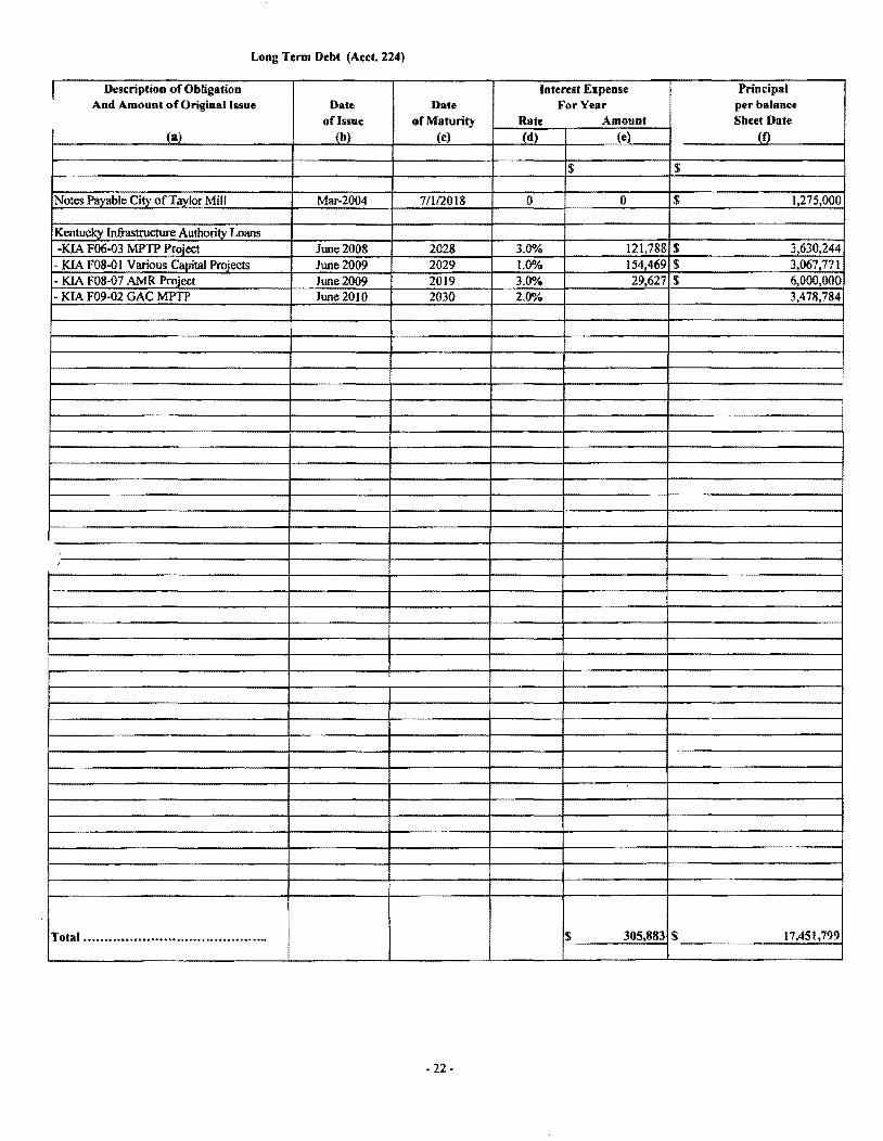
Long Term Debt (Acct. 224)
I Description of Obligation Interest Expense Principal And Amount of Original Issue Date Date For Year per balaDce
of Issue of Maturity Rate Amount Sheet Date (a) (b) (e) (d) (e) (t)
$ $
Notes Payable City of Taylor Mill Mar-2004 7/112018 0 ° $ 1,275,000
Kentucky Infrastructure Authority Loans -KIA F06-03 J'v[PTP Project June 2008 2028 3.00A. 121,788 $ 3,630,244
- KIA F08-0 I Various Capital Projects June 2009 2029 1.0% 154,469 $ 3,067,771 • KIA F08-07 AMR Project June 2009 2019 3.0% 29,627 $ 6,000,000 - KIA F09·02 GAC MPTP June 2010 2030 2.0% 3,478,784
;
Total ............................................ $ 305,883 $ 17,451,799
- 22·

Account 221, BONDS
Line Par Value of Cash Realized on Par Value of Interest During Year No, Actual Issue Actual Issue Amount Held by or Actually Outstanding Actually
for Respondent at Close of year Accrued Paid 1 2 3 4 5 6
1 11,225,000 11,131,694 1,855,000 91,972 111,269 2 11,355,000 11,141,619 8,430,000 410,992 416,830 3 2,287,000 2,287,000 2,054,000 103,217 103,475 4 16,325,000 15,835,250 14,520,000 697,535 698,878 5 45,485,000 44,121,624 42,440,000 2,077,634 2,086,353 6 10,575,000 10,525,204 5,840,000 238,566 250,675 7 1,615,000 1,583,553 1,360,000 60,136 60,686 8 30,270,000 30,068,115 24,110,000 933,716 944,487 9 23,790,000 23,532,357 14,995,000 583,719 600,031 10 10,455,000 10,195,116 8,735,000 368,057 371,869 11 29,000,000 28,736,444 26,455,000 1,100,671 1,113,588 12 29,290,000 27,430,236 27,645,000 1,521,866 1,531,944
Total 221,672,000 216,588,212 - 178,439,000 8,188,081 8,290,085
Schedule of Bond Maturities
Line Band Maturity Interest PrinCipal Amount Amount Paid Remaining Bonds No. Numbers Date Rate Outstanding
7 8 9 10 11 12 1 2 See Attachments 23.1 Through 23.11 3 4 5 6 7 8 9
10 11 12 13 14 15
-23-

Northern Kentucky Water Service District Attachment 23.1 Bond Issue: 11,225,000 , Dated September 1, 1997 "\ Bond Maturity Interest Principle Amounts Outstanding
i
Number Date Rate Amount Paid Registered 1998 4.700% 210,000.00 210,000.00 Re~istered 1999 4.700% 580,000.00 580,000.00 Registered 2000 4.700% 610,000.00 610,000.00 Registered 2001 4.700% 640,000.00 640,000.00 Registered 2002 4.700% 670,000.00 670,000.00 Registered 2003 4.700% 700,000.00 700,000.00 Registered 2004 4.700% 735,000.00 735,000.00 Registered 2005 4.700% 770,000.00 770,000.00 Registered 2006 4.700% 810,000.00 810,000.00 Registered 2007 4.700% 850,000.00 850,000.00 Registered 2008 4.750% 890,000.00 890,000.00 Registered 2009 4.750% 930,000.00 930,000.00 Registered 2010 4.750% 975,000.00 975,000.00 Registered 2011 4.750% 1,025,000.00 1,025,000.00 Registered 2012 4.750% 60,000.00 60,000.00 Registered 2013 4.750% 60,000.00 60,000.00 Registered 2014 4.750% 65,000.00 65,000.00 Registered 2015 4.750% 70,000.00 70,000.00 ~egistered 2016 4.750% 70,000.00 70,000.00 Registered 2017 4.750% 75,000.00 75,000.00 Registered 2018 . 4.750% 80,000.00 80,000.00 ~egistered 2019 4.750% 80,000.00 80,000.00 Registered 2020 4.750% 85,000.00 85,000.00 Registered 2021 4.750% 90,000.00 90,000.00 Registered 2022 4.750% 95,000.00 95,000.00
TOTALS 11,225,000.00 9,370,000.00 1,855,000.00
23.1

Northern Kentucky Water Service District Attachment 23.2 Bond Issue: 11,355,000, Dated December 1,1998 , , Bond Maturity Interest Principle Amounts Outstanding
Number Date Rate Amount Paid Registered 02/0111999 4.700% 250,000.00 250,000.00 Registered 02/01/2000 4.700% 200,000.00 200,000.00 Registered 02/01/2001 4.700% 200,000.00 200,000.00 Registered 02/01/2002 4.700% 210,000.00 210,000.00 Registered 02101/2003 4.700% 220,000.00 220,000.00 Registered 02/01/2004 4.700% 230,000.00 230,000.00 Registered 02101/2005 4.700% 240,000.00 240,000.00 Registered 02/01/2006 4.700% 255,000.00 255,000.00 Registered 02/01/2007 4.700% 265,000.00 265,000.00 Registered 02/01/2008 4.750% 280,000.00 280,000.00 Registered 02/01/2009 4.750% 280,000.00 280,000. Registered 02101/2010 4.750% 295,000.00 295,000. Registered 02/01/2011 4.750% 310,000.00 310,000.00 Registered 02/01/2012 4.750% 325,000.00 325,000.00 Registered 02/01/2013 4.800% 340,000.00 340,000.00 Registered 02101/2014 4.B50% 360,000.00 360,000.00 Registered 02/01/2015 4.B75% 375,000.00 375,000.00 Registered 02101/2016 4.B75% 395,000.00 395,000.00 Registered 02/01/2017 4.B75% 415,000.00 415,000.00 Registered 02/01/2018 4.875% 435,000.00 435,000.00 Registered 02/01/2019 4.B75% 455,000.00 455,000.00 Registered 02/01/2020 4.B75% 480,000.00 480,000.00 Registered 02/01/2021 4.875% 505,000.00 505,000.00 Registered 02/01/2022 4.875% 530,000.00 530,000.00 Registered 02101/2023 4.875% 555,000.00 555,000.00 Registered 02/01/2024 4.875% 585,000.00 585,000.00 Registered 02/01/2025 4.875% 610,000.00 610,000.00 Registered 02/01/2026 4.875% 645,000.00 645,000.00 Registered 02/01/2027 4.875% 675,000.00 675,000.00 Registered 02/01/2028 4.875% 435,000.00 435,000.00
TOTALS 11,355,000.00 2,925,000.00 8,430,000.00
23.2

Northern Kentucky Water Service District Attachment 23.3 FmHA Load $2,287,000 • 2000 '\ Maturity Interest Principle Amounts Outstanding
Year Date Rate Amount Paid 2000 0.00 0.00 0.00 2001 0.00 0.00 0.00 2002 21,000.00 21,000.00 0.00 2003 22,000.00 22,000.00 0.00 2004 24,000.00 24,000.00 0.00 2005 _ 24,000.00 24,000.00 0.00 2006 26,000.00 26,000.00 0.00 2007 27,000.00 27,000.00 0.00 2008 28,000.00 28,000.00 0.00 2009 30,000.00 30,000.00 0.00 2010 31,000.001 31,000.00 0.00 2011 33,000.00 33;000.00 2012 34,000.00 34,000.00 2013 36,000.00 36,000.00 2014 38,000.00 38,000.00 2015 40,000.00 40,000.00 2016 42,000.00 42,000.00 2017 44,000.00 44,000.00 2018 46,000.00 46,000.00 2019 49,000.00 49,000.00 2020 51,000.00 51,000.00
; 2021 54,000.00 54,000.00 2022 56,000.00 56,000.00 2023 59,000.00 59,000.00 2024 62,000.00 62,000.00 2025 65,000.00 65,000.00 2026 68,000.00 68,000.00 2027 72,000.001 72,000.00 2028 75,000.00 75,000.00 2029 79,000.00 79,000.00 2030 83,000.00 83,000.00 2031 87,000.00 87,000.00 2032 92,000.00 92,000.00 2033 96,000.00 96,000.00 2034 102,000.00 102,000.00 2035 107,000.00 107,000.00 2036 112,000.00 112,000.00 2037 118,000.00 118,000.00 2038 124,000.00 124,000.00 2039 130,000.00 130,000.00
Totals 2,287,000.00 233,000.00 2,054,000.00
23.3

Northern Kentucky Water Service District Attachment 23.4 Bondlusse $16,325,000.00 Dated 10-23-2001
. '\ Bond Maturity Interest Principle ) Amounts Outstanding ,I
Number Date Rate Amount Paid Registered 2/1/2002 2.700% 285,000.00 285,000.00 Rlagistered 211/2003 3.000% 235,000.00 235,000.00 Registered 2/1/2004 3.250% 240,000.00 240,000.00 Registered 2/1/2005 3.450% 230,000.00 230,000.00 Registered 2/1/2006 3.600% 215,000.00 215,000.00 Registered 2/1/2007 3.750% 200,000.00 200,000.00 Registered 2/1/2008 3.900% 170,000.00 170,000.00 Registered 2/1/2009 4.000% 155,000.00 155,000.00 Registered 2/112010 4.100% 75,000.00 75,000.00 Registered 2/1/2011 4.200% 80,000.00 80,000.00 Registered 2/1/2012 4.350% 80,000.00 80,000.00 Registered 2/112013 4.450% 735,000.00 735,000.00 Registered 2/1/2014 4.550% 770,000.00 770,000.00 Registered 2/1/2015 4.670% 810,000.00 810,000.00 Registered 2/1/2016 4.750% 845,000.00 845,000.00 Registered 2/1/2017 4.820% 890,000.00 890,000.00 Registered 211/2018 4.850% 930,000.00 930,000.00 Registered 2/1/2019 4.900% 980,000.00 980,000.00 Registered 211/2020 4.950% 1,030,000.00 1,030,000.00 Registered 211/2021 5.000% 1,080,000.00 1,080,000.00 Registered 2/1/2022 5.000% 1,135,000.00 1,135,000.00 Registered 211/2023 5.000% 1,190,000.00 1,190,000.00 Registered 2/1/2024 5.100% 1,255,000.00 1,255,000.00 Registered 21112025 5.100% 1,320,000.00 1,320,000.00 Registered 21112026 5.100% 1,390,000.00 1,390,000.00
TOTALS 16,325,000.00 1,805,000.00 14,520,000.00
23.4

Northern Kentucky Water Service District Attachment 23.5 Bondlusse $45,485,000.00 Dated 211/2002 ,
" Bond Maturity Interest Principle Amounts Outstanding Number Date Rate Amount Paid
Registered 211/2003 Registered 2/1/2003 4,50% 350,000.00 350,000.00 0.00 Registered 2/1/2004 4.50% 345,000.00 345,000.00 0.00 Registered 211/2005 4.50% 360,000.00 360,000.00 0.00 Registered 2/1/2006 4.50% 370,000.00 370,000.00 0.00 Registered 2/1/2007 4.50% 380,000.00 380,000.00 0.00 Registered 2/1/2008 4.50% 410,000.00 410,000.00 0.00 Registered 2/1/2009 4.50% 365,000.00 365,000.00 0.00 Registered 2/1/2010 4.50% 465,000.00 465,000.00 0.00 Registered 2/1/2111 4.50% 485,000.00 485,000.00 Registered 2/1/2012 4.50% 1,530,000.00 ' 1,530,000.00 Registered 2/1/2013 4.50% 950,000.00 950,000.00 Registered 211/2114 4.50% 990,000.00 990,000.00 Registered 2/1/2115 4.65% 1,035,000.00 1,035,000.00 Registered 211/2116 4.75% 1,100,000.00 1,100,000.00 Registered 2/1/2117 4.75% 1,625,000.00 1,625,000.00 Registered 2/1/2118 4.75% 2,520,000.00 2,520,000.00 Registered 211/2119 4.75% 2,640,000.00 2,640,000.00 Registered 211/2020 5.00% 3,080,000.00 3,080,000.00 Registered 2/1/2021 5.00% 3,240,000.00 3,240,000.00 Registered 211/2022 5.00% 3,405,000.00 3,405,000.00
\ Registered 211/2023 5.00% 3,580,000.00 3,580,000.00 I Registered 2/1/2024 5.00% 3,765,000.00 3,765,000.00
Registered 2/1/2025 5.00% 3,960 000.00 3,960,000.00 Registered 2/1/2026 5.00% 4,160,000.00 4,160,000.00 Registered 211/2027 5.00% '4,375,000.00 4,375,000.00
TOTALS 45,485,000.00 3,045,000.00 42,440,000.00
23.5

I~orthern Kentucky Water Service District Attachment 23.6 I:!ond lusse $10,575,000.00 Dated 12/512002
jBond Maturity , Interest Principle Amounts Outstanding Number, Date Rate Amount Paid
Registered 12/5/2002 Registered 21112003 3.00% 535,000.00 535,000.00 0.00 Registered 211/2004 3.00% 455,000.00 455,000.00 0.00 Registered 21112005 3.00% 490,000.00 490,000.00 0.00 Registered 2/1/2006 3.00% 530,000.00 530,000.00 0.00 Registered 2/1/2007 3.50% 580,000.00 580,000.00 0.00 Registered 211/2008 3.50% 625,000.00 625,000.00 0.00 Registered 211/2009 3.50% 745,000.00 745,000.00 0.00 Registered' 211/2010 3.75% 775,000.00 775,000.00 0.00 Registered 2/1/2111 4.00% 805,000.00 805,000.00 Registered 2/1/2012 4.00% 835,000.00 835,000.00 Registered 211/2013 4.00% 870,000.00 870,000.00 Registered 211/2114 4.00% 900,000.00 900,000.00 Registered 211/2115 4.00% 930,000.00 930,000.00 Registered 2/112116 4.00% 965,000.00 965,000.00 Registered 211/2117 4.00% 535,000.00 535,000.00
TOTALS 10,575,000.00 4,735,000.00 5,840,000.00
23.6
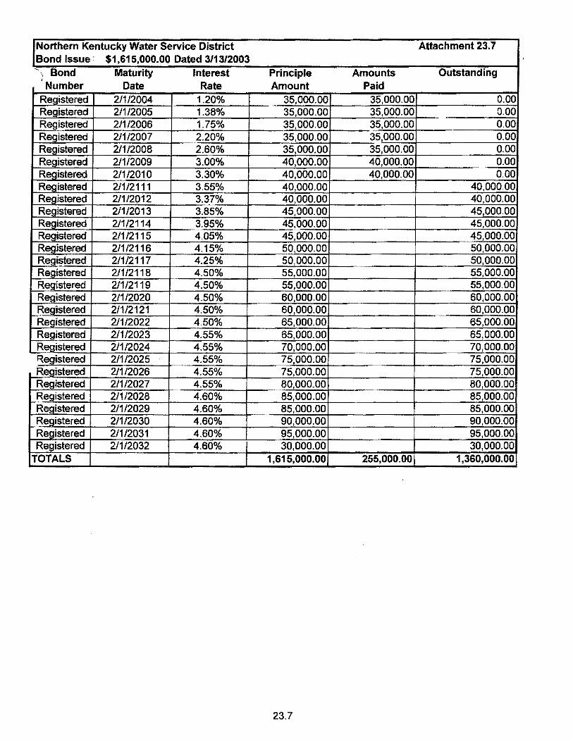
Northern Kentucky Water Service District Attachment 23.7 Bond Issue: $1,615,000.00 Dated 3/13/2003 "' \ Bond Maturity Interest Principle Amounts Outstanding ,
Number Date Rate Amount Paid Registered 211/2004 1.20% 35,000.00 35,000.00 0.00 Registered 2/1/2005 1.38% 35,000.00 35,000.00 0.00 Registered 211/2006 1.75% 35,000.00 35,000.00 0.00 Registered 211/2007 2.20% 35,000.00 35,000.00 0.00 Registered 2/1/2008 2.60% 35,000.00 35,000.00 0.00 Registered 2/1/2009 3.00% 40,000.00 40,000.00 0.00 Registered 2/1/2010 3.30% 40,000.00 40,000.00 0.00 Registered 211/2111 3.55% 40,000.00 40,000.00 Registered 211/2012 3.37% 40,000.00 40,000.00 Registered 2/1/2013 3.85% 45,000.00 45,000.00 Registered 211/2114 3.95% 45,000.00 45,000.00 Registered 211/2115 4.05% 45,000.00 45,000.00 Registered 2/1/2116 4.15% 50,000.00 50,000.00 Registered 211/2117 4.25% 50,000.00 50,000.00 Registered 2/1/2118 4.50% 55,000.00 55,000.00 Registered 2/1/2119 4.50% 55,000.00 55,000.00 Registered 2/1/2020 4.50% 60,000.00 60,000.00 Registered 211/2121 4.50% 60,000.00 60,000.00 Registered 2/1/2022 4.50% 65,000.00 65,000.00 Registered 2/112023 4.55% 65,000.00 65,000.00 Registered 2/1/2024 4.55% 70,000.00 70,000.00 Registered 2/1/2025 4.55% 75,000.00 75,000.00 Registered 2/1/2026 4.55% 75,000.00 75,000.00 Registered 211/2027 4.55% 80,000.00 80,000.00 Registered 2/1/2028 4.60% 85,000.00 85,000.00 Registered 211/2029 4.60% 85,000.00 85,000.00 Registered 211/2030 4.60% 90,000.00 90,000.00 Registered 2/1/2031 4.60% 95,000.00 95,000.00 Registered 2/1/2032 4.60% 30,000.00 30,000.00
TOTALS 1,615,000.00 255,000.00 1,360,000.00
23.7
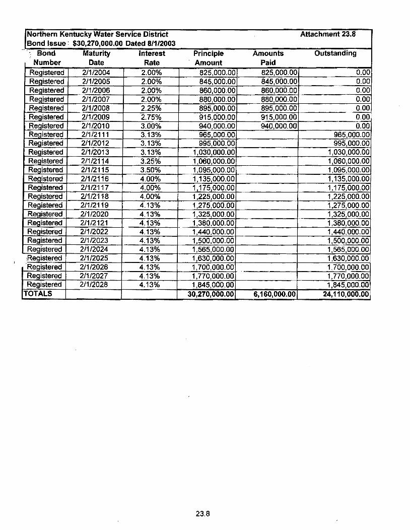
Northern Kentucky Water Service District Attachment 23.8 Bond Issue: $30,270,000.00 Dated 8/1/2003 " Bond Maturity Interest Principle Amounts Outstanding i
Number Date Rate Amount Paid Registered 21112004 2.00% 825,000.00 825,000.00 0.00 Registered 211/2005 2.00% 845,000.00 845,000.00 0.00 Registered 211/2006 2.00% 860,000.00 860,000.00 0.00 Registered 21112007 2.00% 880,000.00 880,000.00 0.00 Registered 2/1/2008 2.25% 895,000.00 895,000.00 0.00 Registered 2/1/2009 2.75% 915,000.00 915,000.00 0.00 Registered 211/2010 3.00% 940,000.00 940,000.00 0.00 Registered 211/2111 3.13% 965,000.00 965,000.00 Registered 2/1/2012 3.13% 995,000.00 995,000.00 Registered 2/112013 3.13% 1,030,000.00 1,030,000.00 Registered 2/1/2114 3.25% 1 ,060,000.00 1,060,000.00 Registered 211/2115 3.50% 1,095,000.00 1,095,000.00 Registered 211/2116 4.00% 1,135,000.00 1,135,000.00 Registered 211/2117 4.00% 1,175,000.00 1,175,000.00 Registered 211/2118 4.00% 1,225,000.00 1.225,000.00 Registered 211/2119 4.13% 1,275,000.00 1,275,000.00 Registered 211/2020 4.13% 1,325,000.00 1,325,000.00 Registered 211/2121 4.13% 1,380,000.00 1,380,000.00 Registered 21112022 4.13% 1,440,000.00 1,440,000.00 Registered 2/1/2023 4.13% 1,500,000.00 1,500,000.00 Registered 2/1/2024 4.13% 1,565,000.00 1,565,000.00 :Registered 2/1/2025 4.13% 1,630,000.00 1,630,000.00 'Registered 211/2026 4.13% 1,700,000.00 1,700,000.00 Registered 211/2027 4.13% 1,770,000.00 1,770,000.00 Registered 2/1/2028 4.13% 1,845,000.00 1,845,000.00
TOTALS 30,270,000.00 6,160,000.00 24,110,000.00
23.8

Northern Kentucky Water Service District Attachment 23.9 Bond Issue: $23,790,000.00 Dated 12118/2003 -.
Bond Maturity Interest Principle Amounts Outstanding Number Date Rate Amount Paid
Registered 2/112004 2.00% 1,430,000.00 1,430,000.00 0.00 Registered 2/1/2005 2.00% 1,160,000.00 1,160,000.00 0.00 Registered 2/112006 2.00% 1,180,000.00 1,180,000.00 0.00 Registered 211/2007 2.25% 1,215,000.00 1,215,000.00 0.00 Registered 21112008 2.50% 1,235,000.~]:= 1,235,000.00 0.00 Registered 2/1/2009 2.75% 1,270,000.00 1,270,000.00 0.00
ed 2/1/2010 3.00% 1,305,000.00 1,305,000.00 0.00 Registered 211/2111 3.25% 1,350,000.00 1,350,000.00 Registered 211/2012 3.50% 1,395,000.00 1,395,000.00 Registered 2/1/2013 3.50% 1,445,000.00 1,445,000.00 Registered 2/1/2114 4.00% 1,505,000.00 1,505,000.00 Registered 2/112115 4.00% 1,565,000.00 1,565,000.00 Registered 211/2116 4.00% 1,625,000.00 1,625,000.00 Registered 211/2117 4.00% 1,690.000~ 1,690,000.00 Registered 2/1/2118 4.00% 1,595,000. 1.595,000.00 Registered 2/1/2119 =t 4.13% 1,665,000.00 1 665,000.00 Registered 2/1/2020 4.25% 1,160,000.00 1,160,000.00
TOTALS 23,790,000.00 8,795,000.00 14,995,000.00
23.9

Northern Kentucky Water Service District Attachment 23.10 Bond Issue $10,455,000.00 11/18/2024
- "l Bond Maturity Interest Principle Amounts Outstanding Number Date Rate Amount Paid
Registered 211/2005 2.000% 270000.00 270,000.00 0.00 Registered 2/1/2006 2.000% 275,000.00 275,000.00 0.00 Registered 21112007 2.125% 285,000.00 285,000.00 0.00 Registered 211/2008 2.375% 290,000.00 290,000.00 0.00 Registered 2/1/2009 2.625% 295,000.00 295,000.00 0.00 Registered 2/1/2010 3.000% 305,000.00 305,000.00 0.00 Registered 211/2111 3.000% 315,000.00 315,000.00 Registered 2/112012 3.250% 325,000.00 325,000.00 Registered 2/1/2013 3.375% 335,000.00 335,000.00 Registered 211/2014 3.500% 345,000.00 345,000.00 Registered 2/112015 4.000% 360,000.00 360,000.00 Registered 2/1/2016 4.000% 375,000.00 375,000.00 Registered 2/1/2017 4.000% 390,000.00 390,000.00 Registered 211/2018 4.000% 405,000.00 405,000.00 Registered 21112019 4.000% 425,000.00 425,000.00 Registered 2/1/2022 4.500% 1,385,000.00 1,385,000.00 Registered 211/2024 4.500% 1,035,000.00 1,035,000.00 Registered 211/2026 4.000% 1,135,000.00 1,135,000.00 Registered 2/1/2029 4.500% 1,905,000.00 1,905,000.00
TOTALS 10,455,000.00 1,720,000.00 8,735,000.00
23.10

I Northern Kentucky Water Service District Attachment 23.11 /Bond Issue 9/1/2006 $29,000,000.00 - ~\ Bond Maturity Interest Principle Amounts Outstanding
Number Date Rate Amount Paid Registered 211/2007 4.000% 300,000.00 300,000.00 0.00 Registered 211/2008 4.000% 720,000.00 720,000.00 0.00 Registered 211/2009 4.000% 750,000.00 750,000.00 0.00 Registered 211/2010 4.000% 775,000.00 775,000.00 0.00 Registered 211/2111 4.000% 805,000.00 805,000.00 Registered 211/2012 4.000% 835,000.00 835,000.00 Registered 2/1/2013 4.000% 870,000.00 870,000.00 Registered 211/2114 4.000% 900,000.00 900,000.00 Registered 211/2115 4.000% 940,000.00 940,000.00 Registered 2/1/2116 4.000% 980,000.00 980,000.00 Registered 2/112117 4.000% 1,020,000.00 1,020,000.00 Registered 2/1/2118 4.000% 970,000.00 970,000.00 Registered 2/1/2119 4.000% 1,010,000.00 1,010,000.00 Registered 211/2020 4.125% 1,320,000.00 1,320,000.00 Registered 2/1/2021 4.125% 1,205,000.00 1,205,000.00 Registered 211/2022 4.125% 1,255,000.00 1,255,000.00 Registered 21112023 4.125% 1,420,000.00 1,420,000.00 Registered 211/2024 4.125% 1,375,000.00 1,375,000.00 Registered 211/2025 4.125% 1,440,000.00 1,440,000.00 Registered 211/2027 4.250% 3,075,000.00 3,075,000.00 Registered 211/2029 4.250% 3.360,000.00 3,360,000.00 ~egistered 2/1/2031 4.273% 3,675,000.00 3,675,000.00
R ~'OTALS 29,000,000.00 2,545,000.00 26,455,000.00
23.11

Northern Kentucky Water Service District Attachment 23.12 Bond Issue 01/06/09 $29,200,000.00 '! Bond Maturity Interest Principle Amounts Outstanding
Number Date Rate Amount Paid Registered 2/112009 3.750% 1,000,000.00 1,000,000.00 0.00 Registered 2/1/2010 3.750% 645,000.00 645,000.00 0.00 Registered 211/2111 3.750% 670,000.00 670,000.00 Registered 211/2012 3.750% 695,000.00 695,000.00 Registered 2/1/2013 3.750% 720,000.00 720,000.00 Registered 211/2114 4.000% 750,000.00 750,000.00 Registered 211/2115 4.125% 780,000.00 780,000.00 Registered 2/1/2116 4.250% 815,000.00 815,000.00 Registered 2/1/2117 4.750% 850,000.00 850,000.00 Registered 211/2118 5.000% 895,000.00 895,000.00 Registered 2/1/2119 5.000% 940,000.00 940,000.00 Registered 2/1/2020 5.125% 990,000.00 990,000.00 Registered 2/1/2021 5.250% 1,040,000.00 1,040,000.00 Registered 2/1/2022 5.375% 1,100,000.00 1,100,000.00 Registered 211/2023 5.500% 1,160,000.00 1,160,000.00 Registered 2/1/2024 5.700% 1,225,000.00 1,225,000.00 Registered 211/2025 5.775% 1,300,000.00 1,300,000.00 Registered 2/1/2027 5.750% 1,375,000.00 1,375,000.00 Registered 2/1/2029 6.000% 1,460,000.00 1,460,000.00 Registered 2/1/2031 6.000% 1,550,000.00 1,550,000.00 R~stered 211/2029 6.000% 1,645,000.00 1.645,000.00 ~egistered 2/1/2030 6.000% 1,745,000.00 1,745,000.00 Registered 211/2031 6.000% 1,855,000.00 1,855,000.00 Registered 211/2032 6.500% 1,975,000.00 1,975,000.00 Registered 2/1/2033 6.500% 2,110,000.00 2,110,000.00
TOTALS 29,290,000.00 1,645,000.00 27,645,000.00
23.12

Notes Payable (Acct 232 & 234)
2010 Nominal Date INTEREST Principal Amount
Date of of Amount per
Issue Maturity Rate of payment Balance Sheet a b c d e f
Account 232 - Note Payable CampbelJ Co. Fiscal Court 0.00% $ $ 100,000
BAN 2009 2.50% 29,160,000
Total Account 232 $ $ 29,260,000
Account 234 - Notes Payable To Associated Companies
N/A $ $
T , Account 234 $ $ I
Accounts Payable to Associated Companies (Acct. 233)
Show Payable to Each Associated Company Separately Amount
$ N/A
Total $
-24-

ACCT, NO, (a)
i
408,1 408,11 408,12 408.13 408.2
408,1 408.11 408.12 408.13 408.2
DESC.DEBT Cal
Acct. No. 237.1 -Accured Interest on Long-term Debt
Series 1997 Series 1998 2000 RUS Loan Series 2001 Series 2002 A Series 2002 B Series 2003 A Series 2003 B Series 2003 C Series 2004 A Series 2006 Series 2009
Total Acct No. 237.1 $
Accl. No. 237.2-Accured Interest on Other liabilities:
2009 BAN # 1-4 KIA $
Total Acet No. 237.2 $
Total Acet No 237 $
Gross Interest expense Less Surcharges Less Capitalized Interest Interest Expense
TAXES ACCRUED (ACCOUNT 236)
2010 DESCRIPTION
(b)
Balance first of year". "', ... '. , .... , .... ,. '" ." .... , .. , .......... $
Accruals Charged: Utility regulatory assessment fees .................. , .... ," Property taxes .................. , ................... , .............. Payroll taxes ..... : ... , ........... '''' .................... " ........ Other taxes and licenses ..................................... Taxes other than income, other income and deductions
Total taxes accrued ....... , ....................... ' ...... , ......... $
Taxes paid during year: Utility regulatory assessment fees .......................... Property taxes .............................. " ..................... Payroll taxes .............. , ........................................ Other taxes and licenses ...................................... Taxes other than income, other income and deductions
Total taxes paid .... , .................... , ....................... ... $
i
Balance end of year ..................................... " .. , .... I
$
ACCRUED INTEREST (ACCOUNT 237)
INTEREST INTEREST BALANCE ACCRUED PAID
BEGINNING DURING DURING OF YEAR YEAR YEAR
(b) (c) (d)
56011 91,972 111.269 176,598 410.992 416,830 17372 103217 103,475
291873 697535 698.878 874,923 2,077.634 2086353 110.503 238,566 250675 25.561 60.136 60686
398922 933,716 944,487 258,169 583719 600,031 156852 368057. 371,869 470,453 1,100671 ' 1 113.588 643349 1,521,866 1531,944
3,480 586 $ 81BB,081 $ 8,290,085 $
99,066 780510 765,255 $ -
99,066 $ 780,510 $ 765,255 i $
I i
3,579.652 $ 8.968,591 $ 9,05~ $
9,091,367 (596,144) (980,700)
7,514,523
-25-
TOTAL ©
-
597489
597489
597489
597,489
-
BALANCE END OF YEAR
(e)
36,714 170760
17,114 290.530 866204 98394 25,011
388,151 241857 153,040 457536 633,271
3,378,582
114,321 -
114,321
3,492903

Miscellaneous Current & Accrued Liabilities (Account 242)
2010 Balance Description End of Year
(a) (b)
Accrued Payroll Taxes &. Misc $ 98,272 Accrued Payroll 146,422 Accrued Sales Taxes 95,036 Accrued Pension 174,138 Accrued Vacation/Sick 806,391 Subdistrict Surcharges Payable 656,119
Total Miscellaneous Current & Accrued Liabilities .............................................. S 1,976,378
Regulatory Commission Expense (Accounts 666 and 667)
2010 TOTAL AMOUNT EXPENSED DURING rNCURRED TRAl"JSFERRED YEAR
DURING TO ACCOUNT DESCRIPTION OF CASE (DOCKET #) YEAR # 186.1 ACCT. AMOUNT
(a) (b) (c) (d) (e)
Rate Case 2005-0148 $ - $ . 667 .$ 181
Rate Case 2007 667 $ 36,914
Rate Case 20 J 0 $ 99,085 $ 108,169 667 -
-26-

WATER OPERATING REVENUE
I 2010 Beginning Year End Acct Year No. Number, No. Description Customer Customers Amounts (a) (b) (e) (d) (e)
Operating Revenues:
460 Unmeter Water Revenue ....... , .... '" ............. , ................... $
461 Meter Water Revenue: $ 461.1 Sales to Residential Customers ..................................... 73.819 73,877 $ 25,358,536 461.2 Sales to Commercial Customers ......... ' ........... , ............... 4,326 4,269 $ 6.333,852 461.3 Sales to Industrial Customers ......................... ,. : ...... , ..... 112 109 $ 3.367,672 461.4 Sates to Public Authorities ... , .......... , ...................... " .... , 492 481 $ 2,169.474 461.5 Sales to Multiple Family Dwellings .................................. 1,634 1.633 $ 3,365,435 461.6 Sales through Bulk Loading Stations ......... , .......... , ...... , ... $ 85,092
Total Metered Sales ........ ••••• ~ , ••• 4 ~ ••••• , •••••••••••• ~ .......... , ••• 80,383 60,369 $ 40,700,061
462 Fire Protection Revenue: $ 462.1 Public Fire Protection $ 462.2 Private Fire Protection 0 0$ 67,256
Total Fire Protection Revenue ........................................ 0 0$ 67,256
464 Other Sales to Public Authorities $ 465 Sales to ........................ , ............ $
I 466 Sales for Resale .......................................................... 3 3$ 1,351,469 467 Interdepartmental Sale .............................. '" ..... ........ , .. $
Total Sales of Water ....................... .. ~ ..... ~ ..... , .............. 80,386 80,372 $ 42,118.805
Other Water Revenues:
469 Guaranteed Revenues ........................ " ......................... ..... ~ ........ ~ .................... $ 470 Forfeited Discounts ...... '" ., ........... , .................................... , ............ .......... ~ ...... $ 765,655 471 Miscellaneous Service Revenues ........................................................................ $ 472 Rents from Water Property ............... '" .............................................................. $ 525,784 473 Interdepartmental Rents ............................................ ..... , ............... ' ~ .................. $ 474 Other Water Revenues .. ; .................................................................................. $ 328.517
Totat Other Water Revenues ................................................... ..................... ~ .... $ 1.619,955
Total Water Operating Revenues ......................................................................... $ 43,738.760
- 27-

WATER UTILITY l:NSE ACCOUNTS -
WATER EXPENSE ACCOUNT MATRIX ,
2010 .1 .2 .3 .4 .5 .6 .7 .8 ;
Source of Source of Supply & Supply & Water Water Trans & Trans & Adminis-Pumping Pumping Treatment Treatment Distribution. Distribution. Customer Trative&
Accl Current Expense- Expense- Expense- Expense- Expense- Expense- Accounts General No Account Name Year Operation Maintenance. Operation Maintenance. Operation Maintenance. Expense Expenses (a) (b) (c) (d) (e) (f) (g) (h) (i) (j) (k)
601 Salaries & Wage - Employees $8,200,584 $1,447,205 $831,251 $904,427 $2,432,151 $1,566,587 $1,028,963 603 Salaries & Wage - Officers $36,000 $36,000 604 Employee Pensions & Benefits $672,925 $130,942 $861,109 $922,508 $666,771 $486,591 610 Purchased Water 615 Purchased Power $697,838 $312,863 '1:1 ?7707Q $147,207 616 Fuel for Power Production 618 Chemicals $1,796,456 620 Materials & Supplies ~ $215,340 $215.440 $151,090 $1,015,914 $233,356 $138,605 631 Contractual Services - Accounting $26,635
$9~~6 $2,600 $24,035
633 Contractual Services - Engineering $138,093 $35,799 $4,952 $91,290 634 Contractual Services - Mgt. Fees $77,059 $77,059 635 Contractual Services - Water Testing $2.962.520 $2,681 $96.396 $1,071,289 $305,312 $865,041 636 Contractual Services - Other $0 641 Rental of Bldg.lReal Property $0 642 Rental of Equipment $4.364 $4,364 650 Transportation Expenses $544,361 $52,659 $41,690 $359,108 $83,841 $7,063 656 Insurance Vehicles $33,631 $5,509 $18,724 $7,778 $1,620 657 Insurance - General Liability $27327511 $87,778 $144,351 $27,431 $13,715 658 Insurance - Workers Compensation $15,342 $22,541 $13,845 $5,803 659 Insurance - Other $53,605 $51,203 660 Advertising Expenses $13,316 $13,316 666 Regulatory Commission Expense -
~ Amortization of Rate Case Expenses 667 Regulatory Commission Expense - Other $102,027 668 Water Resource Conservation 670 Bad Debt Expense $575,520 $575,520 675 Misce"aneous Expenses $62,331 $7,332 $10,503 $32.67~
699 Taxes $0
Total Water Utility Expenses $23,154,089 $700,519 $9,200 $5,055,648 $1,407,159 $3,563,138 $5,815,837 $3,480,376 $3,122,21.
- 28-

Pumping and Purchased Water Statistics
2010 Water Purchased Water Pumped Total Water Water Sold to for Resale From Plants Pumped and Customers
(Omit OOO's) (Omit OOO's) Purchased (Omit OOO's) (Omit OOO's)
a b c d e -
January 798,696.0 798,696.0 557,676.6 February 724,465.0 724,465.0 516,549.4 March 796,545.0 796,545.0 819,495.5 April 777,812.0 777,812.0 592,423.0 May 846,785.0 846,785.0 607,069.3 June 878,758.7 878,758.7 869,593.2 Jnly 997,531.2 997,531.2 639,975.9 August 1,112,246.7 1,112,246.7 598,645.2 September 1,046,954.0 1,046,954.0 1,155,084.1 October 947,934.3 947,934.3 787,291.2 November 766,911.3 766,911.3 712,312.2 December 768,925.5 768,925.5 1,079,597.3
Total for year 10,463,564.7 10,463,564.7 8,935,712.9
Maximum gallons pumped by all methods in anyone day: (Omit OOO's) 42,238.0 8/30/2010
Minimum gallons pumped by all methods in anyone day (Omit OOO's): 21,802.0 11/26/2010
If water is purchased for resale, indicate the foHoinwg: Vendor: Point of delivery:
If water is sold to other water uti! ities for redistribution, list names of such utilities below: ~
Maximum Daily Maximum Monthly
. Pendleton County Water District @ K Y 17 OOO's 207 10,621
City of Walton OOO's 542 18,708
Bullock Pen Water District OOO's 481 43,757
)
G:rk:ss:PumpPurStats31 -29-

Sales for Resale (466) 2010
Line Company Oallons(000'5 ) A vg. Rate (Cents) Amount
1 Pendleton County Water Dist. 104,902.5 2.97/1,OOOgals $313,846.38
2 City of Walton 180,083.2 2.97/1,000gals $535,202.34
3 Bullock Pen Water District 168,711.4 2.97/1,OOOgals $502,440.05
4
5
6
7
8
Total 453,697.1 51,351,488.77
WATER ST A TISTICS
Line Item Gallons (OOO's)
I WATER PRODUCED, PURCHASED, & DISTRIBUTED
2 Water Produced 10,463,564.7
3 Water Purchased
4 TOTAL PRODUCED AND PURCHASED 10,463,564.7
5
6 WATER SALES:
7 Residential 5,669,549.1
8 Commercial 1,515,372.5
9 Industrial 928,878.4
10 Irrigation '
11 Resale 453,697.1
12 Other Sales 368,216
13 TOTAL WATER SALES 8,935,712.9 14 15 OTHER WATER USED (estimate portions not metered) 16 Utility/water treatment plant 199,654.0 17 Wastewater plant 18 System flushing 246,783.2 19 Fire Department 4,541.7 20 Other (construction, flushing, disinfection, ect.) 42,625.3 21 TOTAL OTHER WATER USED 493,604.2 22 23 Water Loss: 24 Tank Overflows 25 Line Breaks 109,449 26 Line Leaks 27 Other 924,799 28 Total Line Loss 1,034,248 29 30 Note: Line 13 + Line 21 + Line 28 Must Equal Line 4 9,538,765.7 31 32 UNACCOUNTED-FOR WATER LOSS PERCENTAGE 33 Line 26 divided by Line 4 9.88%
-30-

PLANT STATISTICS
Give the following information:
1 Number of fire hydrants, by size. 2 Number of private fire hydrants, by size. 3 Wheter water supply is river, impounded streams, well, springs. artificial lake or
collector type well. 4 Wether supply is by gravity, pumping, or a combination. 5 Type, capacity, and elevation of resrviors at overflow and ground level. 6 Miles of main by size and kind. 7 Types of filters: gravity or pressure. number of units, and total rated capacity in
gallons per minute. 8 Type of chlornators, number of units and capacity in pounds per 24 hours. 9 Station equipment. List each pump separately, giving type and capacity and H.P.
of driving unit and character of driving unit (steam, electric, or internal combustion). State whether pump is high or low duty.
10 Quantity of fuel used: coal in pounds, gas in cu. ft., oil in gallons, and electriC in KWH. 11 Give a description and total cost of any sizable additions or retirements to plant in
service outside the normal system growth for the period covered by this report. 12 Capacity of clear well. 13 Peak month, in gallons of water sold. 14 Peak day, in gallons of water sold.
1) Kenton County 6,864; Campbell County 2,874.
2) 70.
3) Rivers: Ohio River and the Liking River.
4) Plants are pumped; Distribution is combination of pumped and gravity.
5} See attached 31A.
6) See attached 31B.
7) Fort Thomas Treatment Plant 12 - Gravity, each 560 sq. ft. - Rated at 5 gpmlft2
Taylor Mill Treatment Plant 8 - Gravity, each 270 Sq. ft. - Rated at 5 gpm/ft2
Memmorial Parkway Treatment Plant 8 - Gravity, each 612 sq. ft.
Actitlo 24gpm/ft2
8) See attached 3iC
9} See attached 310
10) N/A
11) None
31

PLANT STA"nS"nCS Cont.
12) Fort Thomas Treatment Plant 1 - 3 million gallons 1 - 3 1/2 million gallons
Taylor Mill Treatment Plant 1 - 3 million gallons
Memorial Parkway Treatment Plant 1 - 1 million gallons
13) September 2, 2009 - 36,188,000gais
14) N/A
32

OATH
Common wealth of __ -J.K""e:!.n....,tu=c=k):~_"L!.1. County of Kenton J SS;
________ JJ'-"!a~ck~B::.:ra~g>Cg"_, C,""",-PA~ ___________ makes oath and says
that he is _______ V"-'l=·ce President of Finance of
Northern Kentuck): Water District
that jt is his duty to have supervision over the books of account of the respondent and to control the manner in which such books are kept; that he knows that such books have, during the period covered by the foregoing report, been kept in good faith in accordance with the accounting and other orders of the Public Service Commission of Kentucky, effective during the said period; that he has carefully examined the said report and to the best of his knowledge and belief the entries contained in the said report have, so far as they relate to matters of account, been accurately taken from the said books of account and are in exact accordance therewith; that be believes that aU other statements of fact contained in the said report are true; and that the said report is a correct and complete statement of the business and affairs of the above-named respondent during the period of time from and including
_______ ~Jan~uat)':=..<-'l'-'-. _",,2=0....,1 O~ ____ to and includine.g _____ --"D~e::ce=:.m~be~r_=3'_'_1....,. 2:<!0::..!1~0
Subscribed and sworn to before me, a ___ ---""N-'-'O=--T=AR~y.:>--=-P=UB=L=IC""_ ___ ~in and for the
State and County above named, this _--1..d."",' '-'8.4...--__ ~_ day of /J1etLC k.. ,2011.
(Apply Seal Here}
My commission expires: ~-'~---'--"-"--=:--------:"'-r--~.~----------.---

Water Storage Facilities Attachment 31A Northem Kentucky Water Dislrid
:age location Overflow Elevation
Feet 1017
1046.7 1040.0 764.0 750.0 829.0
939.5 1082.0 1042.0 100 831.0 889.5 876.0 674.0 666.0 140 631.0 889.5 676.0 874.0 866.0 140 734.0 765.3 764.5 762.0 760.0 730.0 n8.5 764.5 763.5 757.5 130
829.0 840.0 1015.0 1005.0 1003.0 1000.0 57 943.5 1080.0 1039.5 74 1 00 945.5 1091.5 1083.5 1081.0 1062.0 50 500000 904.0 1017.0 500000 896.0 1054.0 1045.0 1043.0 1033.0 50 500,000 829.0 1017.0 275000 863.0 1017.0 300 000
741.0 3,000000 1976 143 987.0 1017.0 1,000 000 1962 191 987.0 1017.0 300,000 1972 155 810.0 965.0 1.000,000
15 509.5 524.5 522.0 520.0 518.0 1,000,000 143 870.0 1010.0 130.0 110.0 329,000
2008 152 867.0 1017.0 66 750000 NKWSD: 36554000
Page 31A

f4t.. I /,,\\..InlYu.::.;..'I' ow I U
Pipe Inventory Length and Diameter by Material
Pipe Diameter, inches Length,feet Length, Miles
Asbestos Cement(Transite) 2.00 1,481.79 0.28
Asbestos Cement(Transite) 3.00 6,415.23 1.22
Asbestos Cement(Transite) 4.00 40,856.49 7.74 Asbestos Cement(Transite) 6.00 104,515.56 19.79
Asbestos Cement(Transite) 8.00 8,018.34 1.52
Cast (ron 0.75 933.70 0.18
Cast fron 1.00 800.03 0.15
Cast fron 2.00 20,544.85 3.89 Cast Iron 3.00 2,389.27 0.45
Cast (ron 4.00 297,921.31 56.42
Cast Iron 6.00 1,198,835.21 227.05
Cast Iron 8.00 273,629.15 51.82
Cast Iron 10.00 71,711.29 13.58
Cast Iron 12.00 212,852.21 40.31
Cast Iron 16.00 53,812.58 10.19 Cast [ron J8.00 107.61 0.02
Cast fron 20.00 55,702.94 10.55
Cast Iron 24.00 33,321.08 6.31
Cast Iron 30.00 11,851.63 2.24
Cast Iron 36.00 85.82 0.02
Concrete 8.00 20.00 0.00 Concrete 18.00 377.78 0.07
Concrete 20.00 27,615.23 5.23
Concrete 24.00 9,506.41 1.80 Concrete 30.00 176.97 0.03
Concrete 36.00 37,651.90 7.13
Copper 1.00 2,793.66 0.53 Copper 1.50 2,475.16 0.47 Copper 2.00 11,683.30 2.21
Ductile Iron 0.75 373.10 0.07 Ductile [ron 1.00 84.48 0.02
Ductile Iron 2.00 9,414.64 1.78 Ductile Iron 3.00 10,766.54 2.04
Ductile Iron 4.00 68,950.99 13.06
Ductile Iron 6.00 801,777.33 IS 1.85
Ductile Iron 8.00 1,107,449.42 209.74
Ductile Iron 10.00 48,008.28 9.09
Ductile Iron 12.00 552,862.51 104.71 Ductile Iron 14.00 224.46 0.04
Ductile Iron 16.00 225,794.79 42.76 Ductile Iron 18.00 718.58 0.14
Ductile Iron 20.00 55,973.77 10.60
Ductile Iron 24.00 106,140.39 20.10
Ductile Iron 30.00 30,546.09 5.79
Ductile Iron 36.00 15,269.68 2.89
Ductile Iron 42.00 18,751.37 3.55
Galvanized L50 269.42 0.05
Lead 0.75 377.67 0.07
MS 1.00 5.48 0.00
Page 1 of2

.... _, .. -
Pipe Inventory Length and Diameter by Material
Pipe Diameter, inches Length,Jeet Length, Miles
Polyethylene 2.00 18,761.33 3.55
PVC 1.00 34.20 0.01
PVC 1.50 1,920.41 0.36
PVC 2.00 58,183.97 11.02
PVC 3.00 70,022.07 13.26
PVC 4.00 20,642.00 3.91
PVC 6.00 158,955.53 30.11
PVC 8.00 710,055.74 134.48
PVC 10.00 132.24 0.03
PVC 12.00 26,709.07 5.06
PVC 16.00 2,905.34 0.55
Steel 0.75 248.61 0.05
Steel 1.00 551.98 0.10
Steel 1.50 332.35 0.06
Steel 2.00 611.04 0.12
Steel 4.00 143.77 0.03
Steel 24.00 84.58 0.02
Total: 6,612,139.73 1,252.30
Page 2 of2

Northern Kentucky Water District Attachment 31 C Chlorinators and Sodium Hypochlorite Feeders In System & Location
Form of Location # of Units Chlorine Type Capacity (ea.)
Sodium Bromley Pump Station 1 Hypochlorite Jesco Pump 1.3 GPH
Sodium West Covington Pump Station 1 Hypochlorite Jesco Pump 2.8 GPH
Sodium Bristow Road Pump Station 2 Hypochlorite Jesco Pump 5 GPH
Sodium Dudley Pump Station 2 Hypochlorite Jesco Pump 15GPH
Sodium
Fort Thomas Treatment Plant 8 Hypochlorite Watson Marlow 150 GPH Sodium
Taylor Mill Treatment Plant 5 Hypochlorite Watson Marlow 52GPH Sodium
Memorial Pky Treatment Plant 4 Hypochlorite Watson Marlow 100 GPH
Page 33 C

(
Booster Pumping Station Facilities Northern Kentucky Water District
PUMP CITY STATION LOCATED LOCATION Ohio River Raw Brent Water Pumping Station #1
(Feeds FTTP)
Latonia Ave. Covington and 35th St. I (Const. 1953) Bromley Bromley
Licking Rlver Raw TaylorMUI Water Pumping Station TaylorMHI Taylor Mill Treatment Plant
Dudley Pike Edgewood 1040 System
Dudley Pike Edgewood 1080 System
Richardson Rd, Independence
Hands Pike COvington
West Covington Covington
Bristow Rd. Independence
(PeerleSS Pumps)
Waterworks Rd Fort Thomas Pump Stn, Venable Speed US2710MGD 670 Alex. Pk.
Fort Thomas
Ripple Creek Cold Spring
Ohio River Raw Fort Thomas Water Pumping Station #2 (Feeds MPTP)
Memorial Parkway Fort Thomas Treatment Plant Raw Water Pumps Carothers Rd. Newport Pump Stn.
Pump Stations
NO'rUM P YEAR HORSE OF TYPE INSTALLED POWER
UNITS 1 VT 2005 1250 2 VT 2005 1250 3 VT 2009 1250 4 VT 2007 1250 5 VT 1999 1250 6 VT 2005 1250 1 HC, 2008 75 2 HC 2008 75 1 VT 2010 75 2 VT 1986 75 3 VT 1986 75 1 VT 1990 350 2 VT 1971 250 3 VT 1993 150 1 VT 1981 600 2 VT 1994 450 3 VT 1997 700 4 VT 2008 1250 5 VT 1974 1250 6 VT 1982 600 1 VT 2009 250 2 VT 2009 250 3 VT 1965 250 4 VT 1979 250 5 VT 1989 600 6 VT 1990 600 7 VT 1990 600 8 VT 2006 600 1 VT 2011 350 2 VT 2006 400 3 VT 1998 400 1 VT 1983 75 2 VT 2009 75 1 VC 1996 40 2 VC 1987 40 1 VT 2002 75 2 VT 2002 75 3 VT 2002 75 1 VT 2000 500 2 VT 2000 500 3 VT 2000 500 1 VT 1990 350 2 VT 1990 350 3 VT 1990 350 4 VT 2006 350 5 VT 2006 350 6 VT 2006 350 1 VC 1991 75 2 VC 2009 75 '3 VC 200B 75
1 VT 1985 800 2 VT 2003 800 3 VT 2002 600
1 VC 2008 75 2 VC 2008 200 3 VC 2008 200 1 VT 1996 150 2 VT 1996 150
Page 33 0
Attachment 310
VOLTS PUMP RATING SERVICE REQUIRED CONTROl PER PUMP TDH TYPE
(GPM) I (FEET) 4160 AUTO 9,455 430 HIGH 4160 AUTO 7,000 430 HIGH 4160 AUTO 9,200 430 HIGH 4160 AUTO 9,200 430 HIGH 4160 AUTO 8,400 430 HIGH 4180 AUTO 9,200 430 HIGH 460 AUTO 900 250 HIGH 460 AUTO 900 250 HIGH 460 AUTO 650 300 HIGH 460 AUTO 700 315 HIGH 460 AUTO 700 340 HIGH 460 AUTO 7640 126 LOW 460 AUTO 6250 126 LOW 460 AUTO 4900 128 LOW 2300 AUTO 6945 250 HIGH 2300 AUTO 8500 145 HIGH 2300 AUTO 5600 385 HIGH 2300 AUTO 7700 392 HIGH 2300 AUTO 6945 365 HIGH 2300 AUTO 6945 250 HIGH 440 AUTO 2500 277 HIGH 440 AUTO 2500 277 HIGH 440 AUTO 2825 270 HIGH 440 AUTO 2222 375 HIGH 460 AUTO 6000 282 HIGH 460 AUTO 6000 282 HIGH 460 AUTO 6000 282 HIGH 460 AUTO 5000 282 HIGH 460 AUTO 2700 324 HIGH 460 AUTO 2500 515 HIGH 460 AUTO 2100 515 HIGH 460 AUTO 500 426 HIGH 460 AUTO 500 428 HIGH 460 AUTO 2000 60 LOW 460 AUTO 2000 60 LOW 460 AUTO 2900 65 LOW 460 AUTO 2900 65 LOW 460 AUTO 2900 65 LOW 480 AUTO 4200 372 HIGH 480 AUTO 4200 372 HIGH 480 AUTO 4200 372 HIGH 460 AUTO 3500 300 HIGH 460 AUTO 3500 300 HIGH 460 AUTO 3500 300 HIGH 460 AUTO 3500 308 HIGH 460 AUTO 3500 30B HIGH 460 AUTO 3500 308 HIGH 460 AUTO 2050 100 LOW 460 AUTO 2050 100 LOW 460 AUTO 2500 90 LOW
2400 AUTO 6000 400 HIGH 2400 AUTO 6000 400 HIGH 2400 AUTO 5500 3BO HIGH
460 AUTO 3472 64 LOW 460 AUTO 6944 64 LOW 460 AUTO 6944 64 LOW 440 AUTO 1BOO 283 HIGH 440 AUTO 1800 263 HIGH

NORTHERN KENTUCKY WATER DISTRICT
Project
Case No. 2011-_ Exhibit F
Tavlor Mill Treatment Plant Advanced Treatment Improvements
Kenton County 184-0457
SCHEDULE OF MORTGAGES, BONDS, NOTES, AND OTHER INDEBTEDNESS

Northern Kentucky Water District Schedule of Outstanding Debt As of February 28, 2011
Description Amount
Bonds
1997 830,000 1998 8,120,000 2000 Rural Development Loan 2,021,000 2001 14,440,000 2002 A 41,955,000 2002 B 5,035,000 2003 A 1,320,000 2003 B 23,145,000 2003 C 13,645,000 2004 8,420,000 2006 25,650,000 2009 26,975,000
Total Bonds $ 171,556,000
Notes
KIA Loans 11,273.080 Taylor Mill purchase note $ 1.275,000 Deferred note payable 100,000 BAN 2009 29,160,000
Total Notes $ 41,808,080
Total Debt $ 213,364,080

NORTHERN KENTUCKY WATER DISTRICT
Project
Case No. 2011-_ Exhibit G
Tavlor Mill Treatment Plant Advanced Treatment Improvements
Kenton County 184-0457
CURRENT BALANCE SHEET AND INCOME STATEMENT

ASSETS CURRENT ASSETS
Cash and Cash Equivalents
Accured Interest Receivable Accounts Receivable
Customers Unbilled Customers Other
Assessments Receivable
Northern Kentucky Water District Balance Sheet
As of February 28, 2011
Inventory Supplies for New Installation and Maintenance, at Cost
Prepaid Items
TQTALCURRENTASSETS
RESTRICTED ASSETS BoonelFlorence Settlement Account Bond Proceeds Fund Debt SelVice ReselVe Account Debt SelVice Account Improvement, Repair & Replacement
TOTAL RESTRICTED ASSETS
NONCURRENT ASSETS Miscellaneous Deferred Charges Capital assets:
Land, System, Buildings and Equipment Construction in Progress
Total capital assets before accumulated depreciation
Less Accumulated Depreciation
Total capital assets before accumulated depreciation
TOTAL NONCURRENT ASSETS
TOTAL ASSETS
2011 2010
$12,837,734 $13,088,737
13,002 46,048
3,323,803 3,465,597 5,400,000 4,700,000
42,768 51,722 92,634 87,322
1.244,207 1,164,761 319,831 324,912
23,273,979 22,929,099
1,604,064 1,998,798 20,041,667 25,852,215 15,957,522 16,441,761 2,803,261 2,144,883 4,254,713 91652,595
44,661,227 56,090,252
7,412,589 8,272,016
337,152,194 315,033,349 40,626,099 38,891,537
3n,n8,293 353,924,886
(85,950,124) (78,145,058)
291,828,169 275,n9,828
299,240,758 284,051,844
367,175,964 363,071,195

Northern Kentucky Water District Balance Sheet
LIABILITIES AND RETAINED EARNINGS
CURRENT LIABILITIES Current Portion of Long Term Debt Accounts Payable Accured Payroll & Liabilities Other Accrued Liabilities
TOTAL CURRENT LIABILITIES
CURRENT LIABILITIES PAYABLE FROM RESTRICTED ASSETS
Accounts Payable Accured Interest Payable
TOTAL CURRENT LIABILITIES PAYA8LE FROM RESTRICTED ASSETS
LONG-TERM DEBT
As of February 28, 2011
Long-Term Portion of Bonded Indebtedness Bond Anticipation Notes Payable Note Payable - Taylor Mill Deferred Note Payable
TOTAL LONG-TERM DEBT
TOTAL LIABILITIES
Unrestricted Retained Earnings TOTAL NET ASSETS
TOTAL LIABILITIES AND NET ASSETS
2011
$7,919,844 1,325,546
226,034 74,375
9,545,799
2,362,062 962,560
3,324,622
180,096,204 29,160,000
1,100,000 100,000
210,456,204
223,326,625
114,998,347 143,849,339
367,175,964
$7,211,736 1,509,260
337,792 73,679
1,472,252 929,537
2,401,789
182,272,332 29,160,000
1,275,000 100,000
212,807,332
109,878,616 138,729,608
363,071! 196

O4f04f11 Northern Kentucky Water District Revenue Budget to Actual
For the Two Months Ending February 28, 2011
February YTD YTD Acct. # Budget Variance Actual Budget Variance
Revenue
(461 TO 466 ... Water Sales $2,546,037 $2,598,096 2% $5,536,495 $5,539,334 0%
(470 TO 470) Forfeited Discounts 49,306 69,400 29% 128,520 149,031 14%
(4720001000 ... Renls from Water Property 39,083 33,000 (18%) 75,042 58,000 (29%)
(471 TO 471 ... Other Water Revenues 25,585 19,979 (28%) 46,760 44,856 (4%)
Total Operating Revenues 2,660,011 2,720,475 2% 5,786,817 5,791,221 0%
Non-Operating Income
4190001000 ... Interest Income 57,660 97,618 41% 130,479 194,812 33%
(474 TO 474 ... Miscellaneous 3,829 7,241 47% 5,238 8,256 37%
Total Non-Operating Income 61,489 104,859 41% 135,717 203,068 33%
Total Revenues 2,721,500 2,825,334 4% 5,922,534 5,994,289 1%