Embed Size (px)
Citation preview

Uni
vers
ity o
f Stu
ttga
rt
Inst
itute
of
Con
stru
ctio
n M
ater
ials
ICC-ES Hearing, Los Angeles, 2015 02 10
Proposed Revisions to the Acceptance Criteria for Anchor Channels in Concrete Elements
Subject AC232-0215-R1 (AHG/HS)
Comments by
Werner Fuchs Tobias Schmidt
Source: baulinks.de
AC232-0215-R1 #2
Uni
vers
ity o
f Stu
ttga
rt
Inst
itute
of
Con
stru
ctio
n M
ater
ials
ICC-ES Hearing, Los Angeles, 2015 02 10
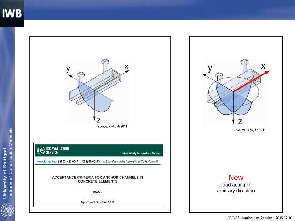
New load acting in
arbitrary direction
Source: Roik, fib 2011 Source: Roik, fib 2011
Uni
vers
ity o
f Stu
ttga
rt
Inst
itute
of
Con
stru
ctio
n M
ater
ials
ICC-ES Hearing, Los Angeles, 2015 02 10
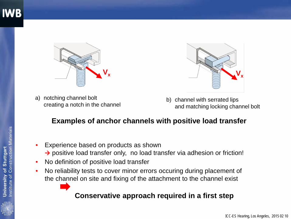
Examples of anchor channels with positive load transfer
• Experience based on products as shown positive load transfer only, no load transfer via adhesion or friction!
• No definition of positive load transfer • No reliability tests to cover minor errors occuring during placement of
the channel on site and fixing of the attachment to the channel exist Conservative approach required in a first step
a) notching channel bolt creating a notch in the channel
b) channel with serrated lips and matching locking channel bolt
Vx Vx
Uni
vers
ity o
f Stu
ttga
rt
Inst
itute
of
Con
stru
ctio
n M
ater
ials
ICC-ES Hearing, Los Angeles, 2015 02 10
Hilti’s initiative to complete AC232 with the application of shear loads acting in the longitudinal axis of the channel and seismic loading is supported. Hilti‘s proposal and further improvement during the rebuttal process represents a good start only requiring • limited ‚retrofitting‘ and • amendment to ensure the desired conservatism Hilti‘s rebuttal rejects significant influencing parameters raised during the public discussion without providing new evidence
General
Uni
vers
ity o
f Stu
ttga
rt
Inst
itute
of
Con
stru
ctio
n M
ater
ials
ICC-ES Hearing, Los Angeles, 2015 02 10
Installation torque
is vital to ensure a robust connection since it creates a prestressing force which shall exceed the external acting load in service over 50 years
testing without an installation torque or handtight would yield to the development of products which do not need an installation torque
Testing with an installation torque similar to the procedure for post-installed anchors is required
Uni
vers
ity o
f Stu
ttga
rt
Inst
itute
of
Con
stru
ctio
n M
ater
ials
ICC-ES Hearing, Los Angeles, 2015 02 10
Prestressing force
is vital to ensure proper functioning of the known products with notching bolts or serrated bolts
Proposed scope also allows other products than notching bolts and serrated channels which might have unknown reliabilty issues other than the installation torque
Continuous inspection is required
Limited experience of installers
Uni
vers
ity o
f Stu
ttga
rt
Inst
itute
of
Con
stru
ctio
n M
ater
ials
ICC-ES Hearing, Los Angeles, 2015 02 10
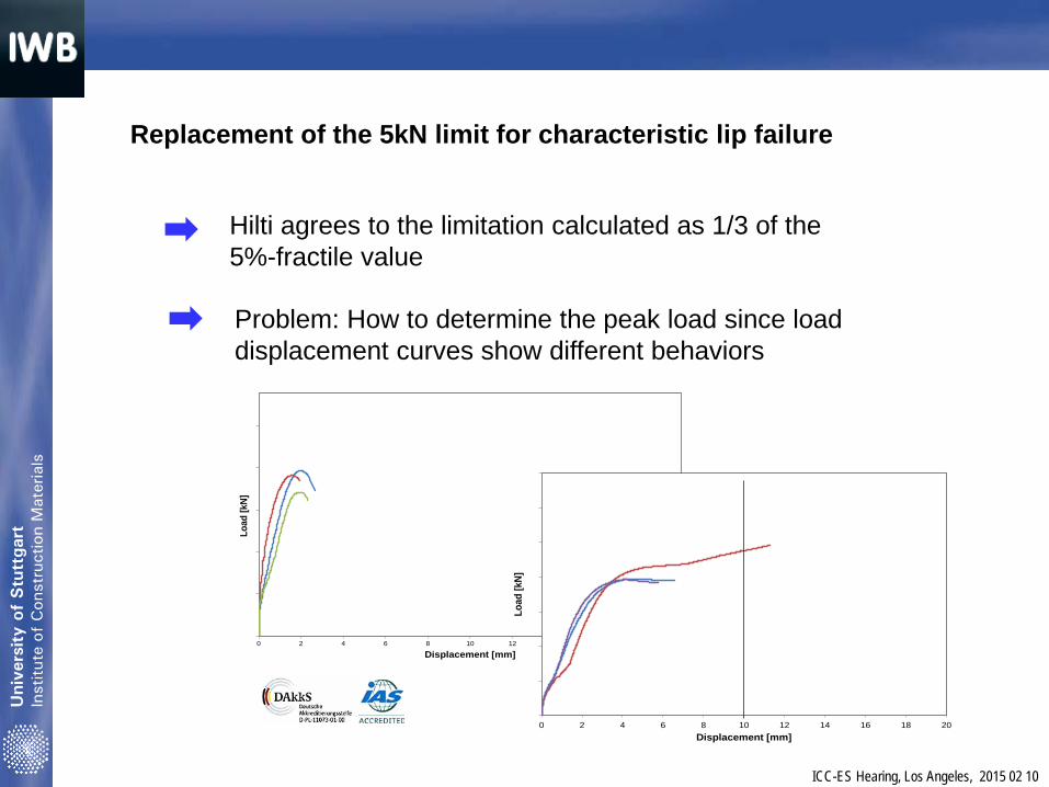
Replacement of the 5kN limit for characteristic lip failure
Hilti agrees to the limitation calculated as 1/3 of the 5%-fractile value
Problem: How to determine the peak load since load displacement curves show different behaviors
1
6
11
16
21
26
0 2 4 6 8 10 12 14 16 18 20
Load
[kN]
Displacement [mm]
0
10
20
30
40
50
60
70
0 2 4 6 8 10 12 14 16 18 20
Load
[kN]
Displacement [mm]
Uni
vers
ity o
f Stu
ttga
rt
Inst
itute
of
Con
stru
ctio
n M
ater
ials
ICC-ES Hearing, Los Angeles, 2015 02 10
0
10
20
30
40
50
60
70
0 2 4 6 8 10 12 14 16 18 20
Load
[kN
]
Displacement [mm]
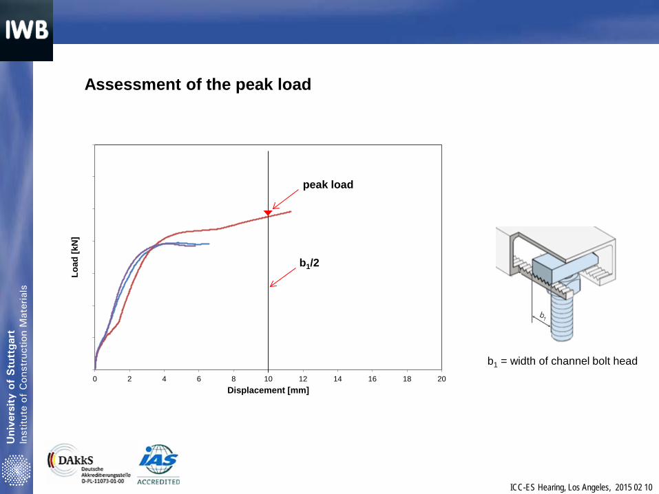
Assessment of the peak load
b1 = width of channel bolt head
b1/2
peak load
Uni
vers
ity o
f Stu
ttga
rt
Inst
itute
of
Con
stru
ctio
n M
ater
ials
ICC-ES Hearing, Los Angeles, 2015 02 10
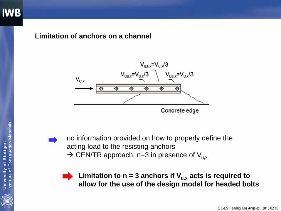
Limitation of anchors on a channel
no information provided on how to properly define the acting load to the resisting anchors CEN/TR approach: n=3 in presence of Vu,x
Limitation to n = 3 anchors if Vu,x acts is required to allow for the use of the design model for headed bolts

Uni
vers
ity o
f Stu
ttga
rt
Inst
itute
of
Con
stru
ctio
n M
ater
ials
ICC-ES Hearing, Los Angeles, 2015 02 10
All shear loads subjected to the front anchor channel
No generally applicable investigations with regard to a design model describing the load transfer to the back anchors are available no technical evidence that the stiffness of the connection between anchor and channel is in any case identical to headed studs welded to a steel plate
Front anchor and channel face are decisive for the serviceability
Uni
vers
ity o
f Stu
ttga
rt
Inst
itute
of
Con
stru
ctio
n M
ater
ials
ICC-ES Hearing, Los Angeles, 2015 02 10
Conclusions
Open issues in addition to the Hilti proposal shall be considered
Proposals based on technical evidence on how to overcome the open points were provided in the IWB letter dated Jan. 9, 2015
Revise AC232 based on Hilti‘s proposal considering the technical evidence
Proposed Revisions to AC 232
Proposed Revisions to AC 232
Andreas Beer
AC232-0215-R1 #2
Proposed Revisions to AC 232
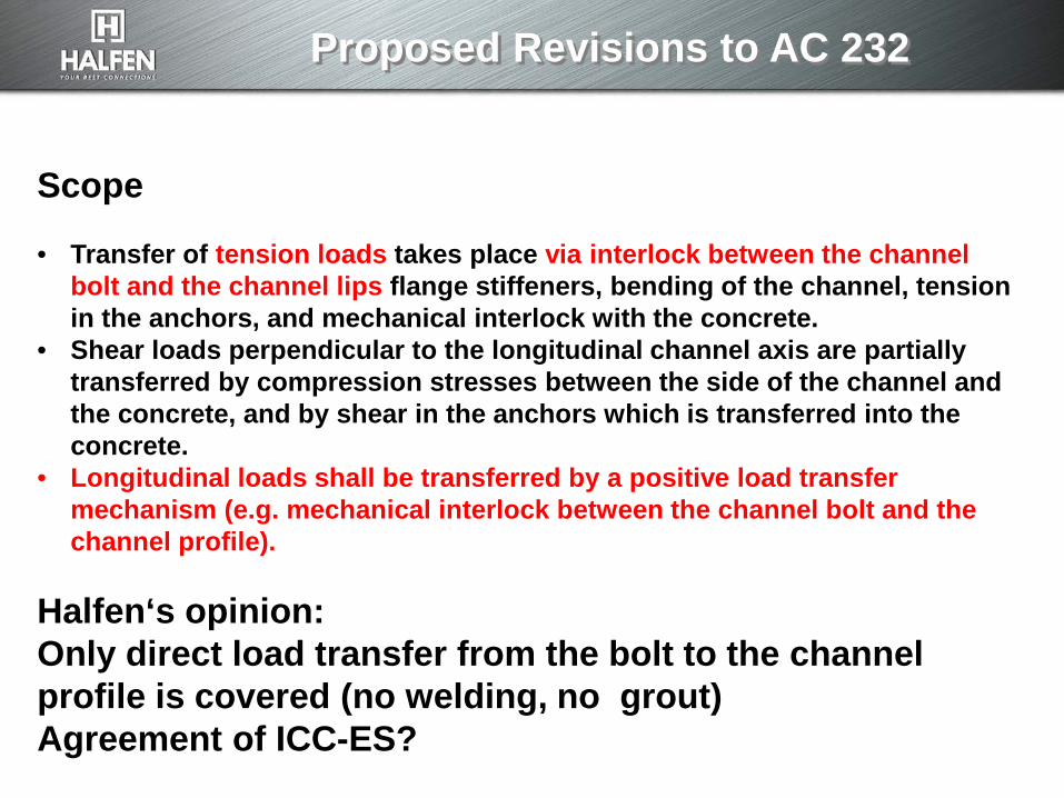
Scope • Transfer of tension loads takes place via interlock between the channel
bolt and the channel lips flange stiffeners, bending of the channel, tension in the anchors, and mechanical interlock with the concrete.
• Shear loads perpendicular to the longitudinal channel axis are partially transferred by compression stresses between the side of the channel and the concrete, and by shear in the anchors which is transferred into the concrete.
• Longitudinal loads shall be transferred by a positive load transfer mechanism (e.g. mechanical interlock between the channel bolt and the channel profile).
Halfen‘s opinion: Only direct load transfer from the bolt to the channel profile is covered (no welding, no grout) Agreement of ICC-ES?
Proposed Revisions to AC 232
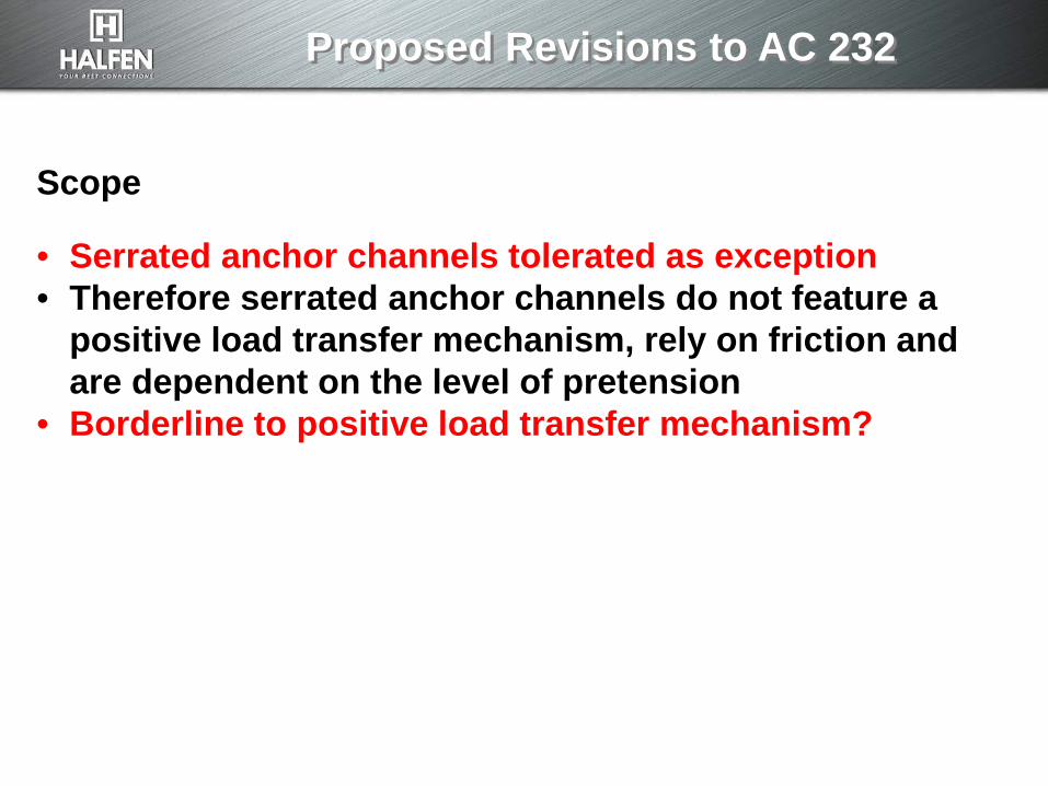
Scope • Serrated anchor channels tolerated as exception • Therefore serrated anchor channels do not feature a
positive load transfer mechanism, rely on friction and are dependent on the level of pretension
• Borderline to positive load transfer mechanism?
Proposed Revisions to AC 232
Testing • An arbitrary tightening torque (20 Nm) provided by a
proponent is not acceptable. • Testing shall be done with the torque specified by the
manufacturer and stated in the MPII
Proposed Revisions to AC 232
Thank you for your attention.
ES Committee Meeting – Proposed changes to AC232 I Dr. Philipp Grosser www.hilti.com 2015-02-10 1
ES Committee Meeting
Los Angeles, Sheraton Gateway Hotel
Tuesday, February 10, 2015
Proposal for implementation of longitudinal shear in
AC232 for both static and seismic loading
Subject AC232-0215-R1 (AHG/HS) P. Grosser
AC232-0215-R1 #2
ES Committee Meeting – Proposed changes to AC232 I Dr. Philipp Grosser www.hilti.com 2015-02-10 2
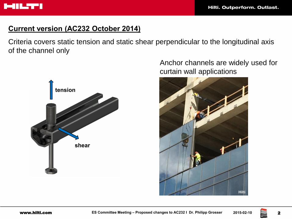
Current version (AC232 October 2014)
Criteria covers static tension and static shear perpendicular to the longitudinal axis
of the channel only
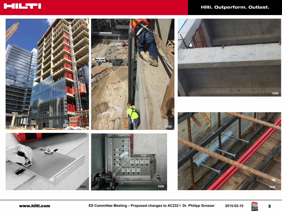
Anchor channels are widely used for
curtain wall applications
Hilti
tension
shear
ES Committee Meeting – Proposed changes to AC232 I Dr. Philipp Grosser www.hilti.com 2015-02-10 3
Hilti
Hilti
Hilti
Hilti Hilti
Hilti
ES Committee Meeting – Proposed changes to AC232 I Dr. Philipp Grosser www.hilti.com 2015-02-10 4
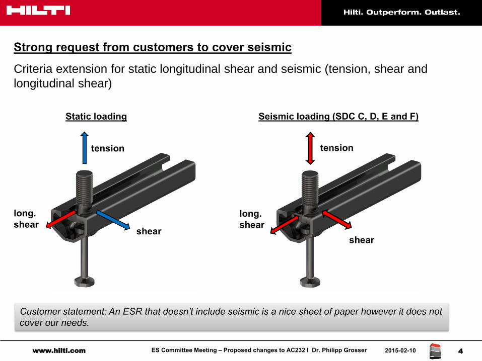
Strong request from customers to cover seismic
Criteria extension for static longitudinal shear and seismic (tension, shear and
longitudinal shear)
long. shear
tension
long. shear
tension
shear
Static loading Seismic loading (SDC C, D, E and F)
shear
Customer statement: An ESR that doesn’t include seismic is a nice sheet of paper however it does not
cover our needs.
ES Committee Meeting – Proposed changes to AC232 I Dr. Philipp Grosser www.hilti.com 2015-02-10 5
Based on input from users, 90% of curtain wall applications require minimal
resistance in the longitudinal direction:
design loads per channel bolt < 670 lb (3kN)
Common solutions used in practice – transfer of longitudinal shear:
Box outs (recessed pockets) / filled channels
Non-serrated channels with notched channel bolts
Welded channels
Installations with additional mechanical attachments
Serrated channels
Independent test results satisfying the requirements of Sec. 104.11 are currently
unavailable. Instead, specifiers and AHJs must rely on
- manufacturer published data
- engineering judgement by specifiers / construction industry
ES Committee Meeting – Proposed changes to AC232 I Dr. Philipp Grosser www.hilti.com 2015-02-10 6
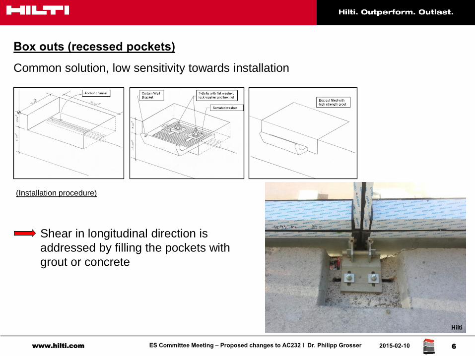
Box outs (recessed pockets)
Common solution, low sensitivity towards installation
(Installation procedure)
Shear in longitudinal direction is
addressed by filling the pockets with
grout or concrete
Hilti
ES Committee Meeting – Proposed changes to AC232 I Dr. Philipp Grosser www.hilti.com 2015-02-10 7
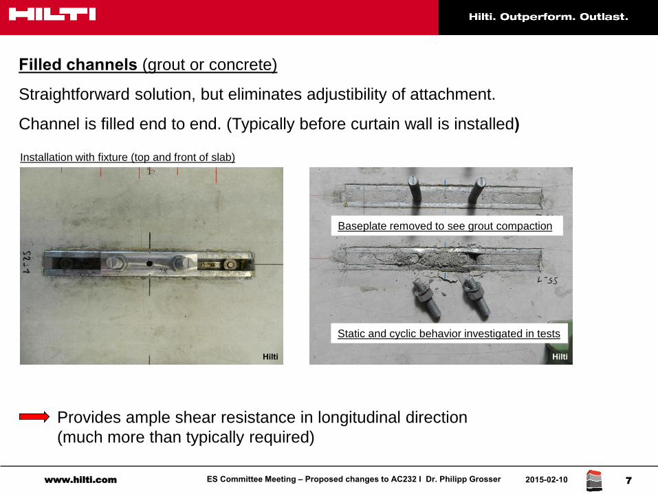
Filled channels (grout or concrete)
Straightforward solution, but eliminates adjustibility of attachment.
Channel is filled end to end. (Typically before curtain wall is installed)
Provides ample shear resistance in longitudinal direction
(much more than typically required)
Installation with fixture (top and front of slab)
Baseplate removed to see grout compaction
Static and cyclic behavior investigated in tests
Hilti Hilti
ES Committee Meeting – Proposed changes to AC232 I Dr. Philipp Grosser www.hilti.com 2015-02-10 8
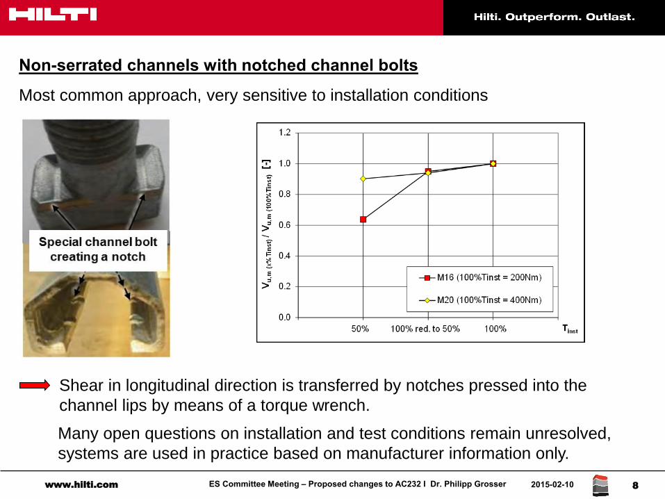
Non-serrated channels with notched channel bolts
Most common approach, very sensitive to installation conditions
Shear in longitudinal direction is transferred by notches pressed into the
channel lips by means of a torque wrench.
Many open questions on installation and test conditions remain unresolved,
systems are used in practice based on manufacturer information only.
ES Committee Meeting – Proposed changes to AC232 I Dr. Philipp Grosser www.hilti.com 2015-02-10 9
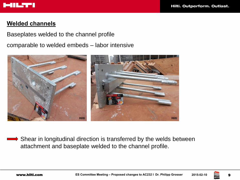
Welded channels
Baseplates welded to the channel profile
comparable to welded embeds – labor intensive
Shear in longitudinal direction is transferred by the welds between
attachment and baseplate welded to the channel profile.
Hilti Hilti
ES Committee Meeting – Proposed changes to AC232 I Dr. Philipp Grosser www.hilti.com 2015-02-10 10
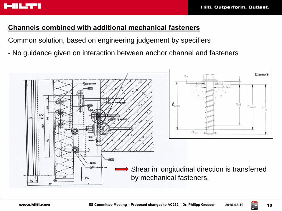
Channels combined with additional mechanical fasteners
Common solution, based on engineering judgement by specifiers
- No guidance given on interaction between anchor channel and fasteners
Shear in longitudinal direction is transferred
by mechanical fasteners.
Example
ES Committee Meeting – Proposed changes to AC232 I Dr. Philipp Grosser www.hilti.com 2015-02-10 11
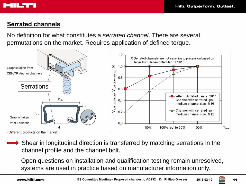
Serrated channels
No definition for what constitutes a serrated channel. There are several
permutations on the market. Requires application of defined torque.
Shear in longitudinal direction is transferred by matching serrations in the
channel profile and the channel bolt.
Open questions on installation and qualification testing remain unresolved,
systems are used in practice based on manufacturer information only.
Serrations
(Different products on the market)
Graphic taken from
CEN/TR Anchor channels
Graphic taken
from Edilmatic
ES Committee Meeting – Proposed changes to AC232 I Dr. Philipp Grosser www.hilti.com 2015-02-10 12
Efforts to implement longitudinal shear and seismic in AC232 (CAMA task group on AC232)
Proposal submitted to CAMA TG by Hilti for consideration at the June hearings 2013 (letter
dated February 22, 2013) → Proposal rejected due to open questions regarding design and
installation conditions
Improved proposal submitted to CAMA TG by Hilti for consideration at the October hearings 2013 (letter dated June 23, 2013) → Proposal rejected, additional questions raised
Open questions
Level of pretension load in qualification tests (steel – steel relaxation?)
Ratio between pretension and tension load based on different production lots
Determination of peak load in case systems are torqued in qualification tests
Torque tests / Installation tests to determine minimum edge distance
Determination of installation safety
Job-site quality control for systems relying on pretension
The discussion in the CAMA task group over the past three years, while productive, has still not resulted in the implementation of seismic qualification criteria in AC232
ES Committee Meeting – Proposed changes to AC232 I Dr. Philipp Grosser www.hilti.com 2015-02-10 13
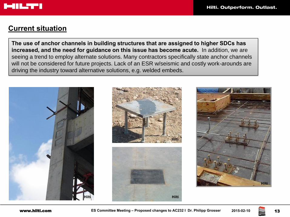
Current situation
The use of anchor channels in building structures that are assigned to higher SDCs has increased, and the need for guidance on this issue has become acute. In addition, we are
seeing a trend to employ alternate solutions. Many contractors specifically state anchor channels
will not be considered for future projects. Lack of an ESR w/seismic and costly work-arounds are
driving the industry toward alternative solutions, e.g. welded embeds.
Hilti
Hilti
Hilti
Hilti
ES Committee Meeting – Proposed changes to AC232 I Dr. Philipp Grosser www.hilti.com 2015-02-10 14
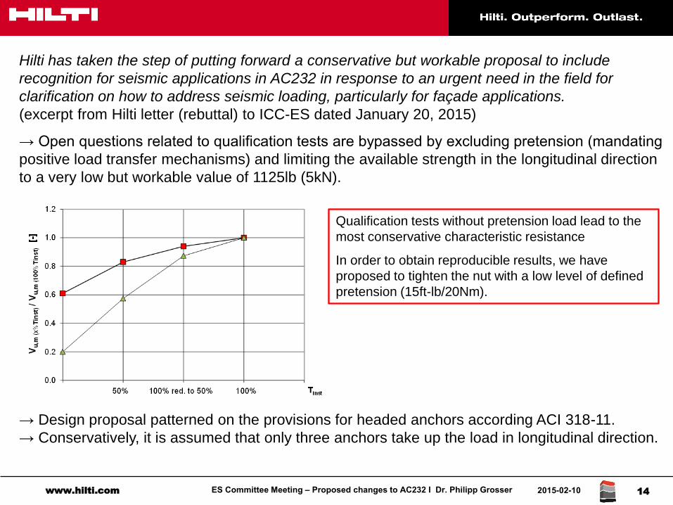
Hilti has taken the step of putting forward a conservative but workable proposal to include
recognition for seismic applications in AC232 in response to an urgent need in the field for
clarification on how to address seismic loading, particularly for façade applications.
(excerpt from Hilti letter (rebuttal) to ICC-ES dated January 20, 2015)
→ Open questions related to qualification tests are bypassed by excluding pretension (mandating
positive load transfer mechanisms) and limiting the available strength in the longitudinal direction
to a very low but workable value of 1125lb (5kN).
→ Design proposal patterned on the provisions for headed anchors according ACI 318-11.
→ Conservatively, it is assumed that only three anchors take up the load in longitudinal direction.
Qualification tests without pretension load lead to the
most conservative characteristic resistance
In order to obtain reproducible results, we have
proposed to tighten the nut with a low level of defined
pretension (15ft-lb/20Nm).
ES Committee Meeting – Proposed changes to AC232 I Dr. Philipp Grosser www.hilti.com 2015-02-10 15
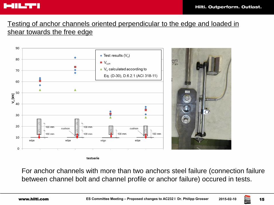
Testing of anchor channels oriented perpendicular to the edge and loaded in
shear towards the free edge
For anchor channels with more than two anchors steel failure (connection failure
between channel bolt and channel profile or anchor failure) occured in tests.
ES Committee Meeting – Proposed changes to AC232 I Dr. Philipp Grosser www.hilti.com 2015-02-10 16
Conclusion
We welcome the overtures from Rolf Eligehausen (IEA) and from the University of Stuttgart
(IWB) to develop a more comprehensive solution. However:
The modifications put forward here by IEA and IWB do not improve the current proposal.
Note that they would increase the permissible characteristic resistance (e.g. allowing a
pretension according to Section 5.5), even though the open questions regarding pretension
have not been resolved.
The changes proposed for the scope mis-apprehend the structure of the proposal. Mandating
positive load transfer systems as the baseline and permitting serrated systems (without
definition) under specific circumstances is the best way forward at this time.
The limit of 1125lb (5kN) is a matter of engineering judgment. We can accept alternate
proposals.
The evaluation of load-displacement curves, etc. will be required for the qualification of
systems that rely on a specified torque. With the exception of serrated channels, such
systems are not addressed by the current proposal.
The proposal to extend continuous inspection to systems utilizing positive load transfer
mechanisms is unnecessary. Cast-in-place headed anchors require periodic inspection in
accordance with Chapter 17. Continuous special inspection is required for post-installed
anchors under specific circumstances (adhesive anchors, sustained loads, etc.)
IEAE
ligeh
ause
n –
Asm
us -
Hof
man
n
Folie 1
AC 232Comments to the proposal of Hilti to include shear
loads in direction of the longitudinal channel axis and
seismic loading in seismic design categories C to E
Rolf EligehausenJörg Asmus
Klaus Schmid
AC232-0215-R1 #2
IEAE
ligeh
ause
n –
Asm
us -
Hof
man
n
Folie 2
• We welcome the efforts by company Hilti to
include shear loads in the direction of the
longitudinal channel axis (longitudinal shear) and
seismic loading, because these amendments are
urgently needed.

IEAE
ligeh
ause
n –
Asm
us -
Hof
man
n
Folie 3
• In general we consider the proposal of Hilti as
conservative.
However, it deviates significantly from the
accepted concept for testing, assessing and
special inspection of post-installed anchors.
Furthermore, for anchor channels with many
anchors the design procedure is not clear.
• For these reasons we propose the following main
modifications.
IEAE
ligeh
ause
n –
Asm
us -
Hof
man
n
Folie 4
Proposal Hilti
• Adhesion for the transfer of longitudinal shear loads
Vu,x from the channel bolt via the channel and the
anchors into the concrete is not excluded.
Proposal IEA
• Exclude adhesion as load transfer mechanism for
Vu,x.
Annex A, Section 1.3.2, Loading on anchor channels – load transfer mechanisms
Load transfer mechanism for Vu,x

IEAE
ligeh
ause
n –
Asm
us -
Hof
man
n
Folie 5
Reasons for our proposal:
- Adhesion between concrete and a smooth steel surface isunreliable and may be destroyed by shrinkage, temperature variation, sustained or cyclic loading.
- Adhesion is not accepted in ACI 318 as a load transfermechanism.Example: Smooth round bars need anchorage bymechanical interlock (hook, end anchor, transversewelded bars) and, in general, are not allowed forseismic loading.
Hilti did not comment on this proposal.
Load transfer mechanism for Vu,x
IEAE
ligeh
ause
n –
Asm
us -
Hof
man
n
Folie 6
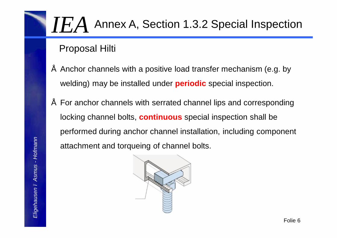
Annex A, Section 1.3.2 Special Inspection
Proposal Hilti
• Anchor channels with a positive load transfer mechanism (e.g. by
welding) may be installed under periodic special inspection.
• For anchor channels with serrated channel lips and corresponding
locking channel bolts, continuous special inspection shall be
performed during anchor channel installation, including component
attachment and torqueing of channel bolts.
IEAE
ligeh
ause
n –
Asm
us -
Hof
man
n
Folie 7
Annex A, Section 1.3.2 Special Inspection
Proposal Hilti
• In addition, the tests to evaluate Vse,x shall be performed on
anchor channels where the channel bolts are torqued with
Tinst = 20 Nm (15ft-lb).
• Depending on channel bolt diameter, this torque moment may be
<10% of Tinst required in the MPII.
IEAE
ligeh
ause
n –
Asm
us -
Hof
man
n
Folie 8
Annex A, Section 1.3.2 Special Inspection
Proposal IEA
Continuous special inspection shall be performed during installation of all types of anchor channels.
IEAE
ligeh
ause
n –
Asm
us -
Hof
man
n
Folie 9
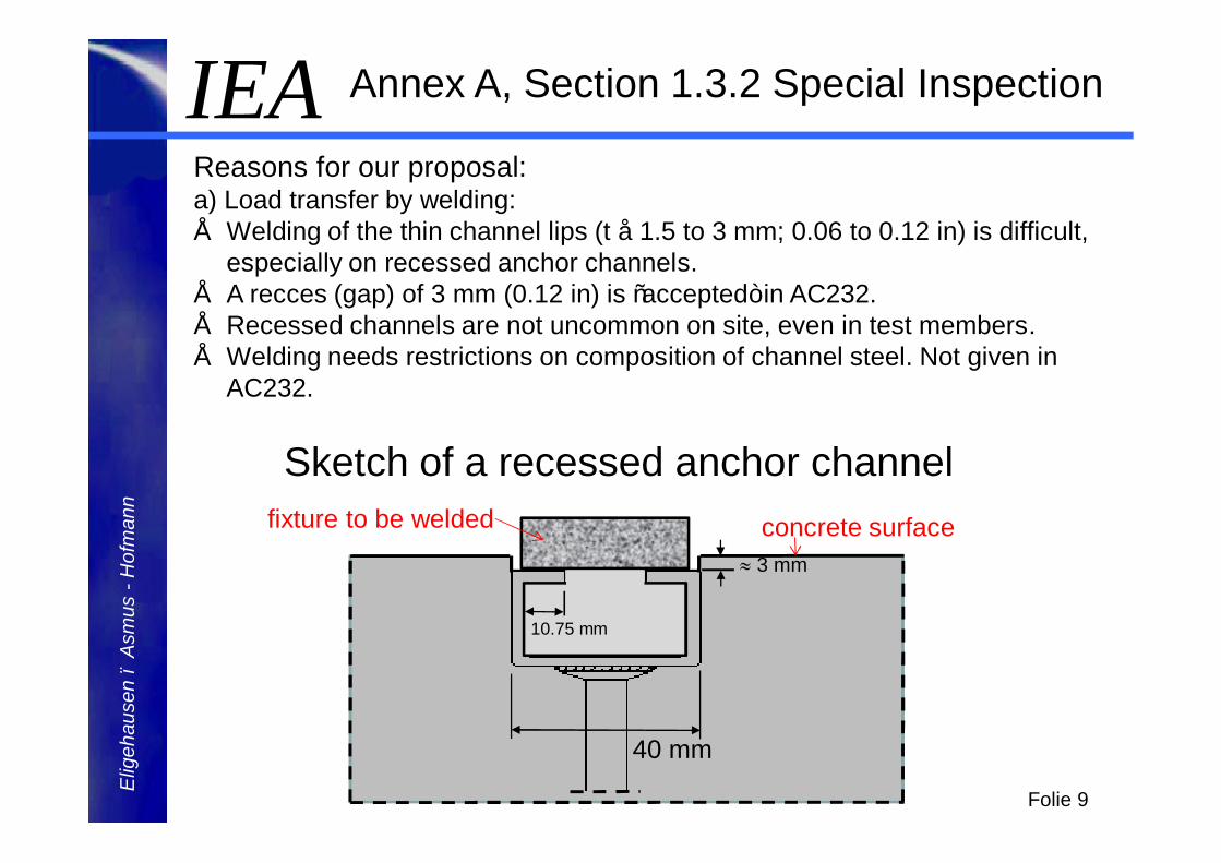
Reasons for our proposal:a) Load transfer by welding: • Welding of the thin channel lips (t ≈ 1.5 to 3 mm; 0.06 to 0.12 in) is difficult,
especially on recessed anchor channels.• A recces (gap) of 3 mm (0.12 in) is “accepted” in AC232.• Recessed channels are not uncommon on site, even in test members.• Welding needs restrictions on composition of channel steel. Not given in
AC232.
Sketch of a recessed anchor channel
Annex A, Section 1.3.2 Special Inspection
40 mm
≈ 3 mm
concrete surfacefixture to be welded
10.75 mm
IEAE
ligeh
ause
n –
Asm
us -
Hof
man
n
Folie 10
b) Load transfer mechanism other than welding:
• These load transfer mechanisms are not commonly
in use yet.
• Anchor channels with this load transfer mechanism
may or may not be sensitive to installation
inaccuracies.
Annex A, Section 1.3.2 Special Inspection
IEAE
ligeh
ause
n –
Asm
us -
Hof
man
n
Folie 11
c) Load transfer by mechanical interlock (anchor channels with
serrated channel lips)
• Anchor channels with serrated channels lips used in Germany are not
much sensitive to a reduction of the applied installation torque – not
more than most torque controlled expansion anchors which may be
installed under periodic special inspection.
• However, shape and dimensions of serrations are not defined.
Therefore, anchor channels with serrations may be on the market that
are much more sensitive to a reduced torque moment during
installation.
• Therefore, continuous special inspection should also be performed for
these types of anchor channels.
Annex A, Section 1.3.2 Special Inspection
IEAE
ligeh
ause
n –
Asm
us -
Hof
man
n
Folie 12
0,00
0,20
0,40
0,60
0,80
1,00
1,20
0 20 40 60 80 100 120
V u,m
(x%
Tins
t)/V
u,m
(100
%Ti
nst)
[-]
Applied torque [%] (100% =Tinst=180 Nm)
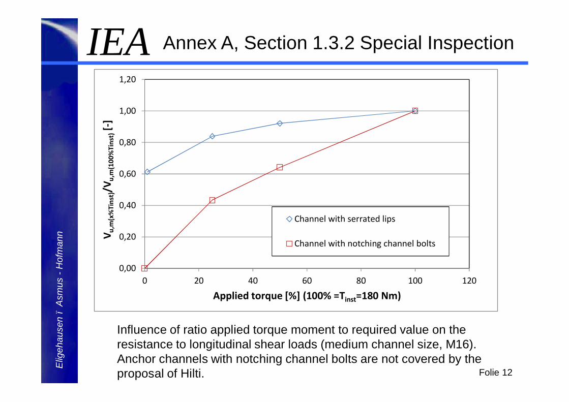
Channel with serrated lips
Channel with notching channel bolts
Influence of ratio applied torque moment to required value on the resistance to longitudinal shear loads (medium channel size, M16). Anchor channels with notching channel bolts are not covered by the proposal of Hilti.
Annex A, Section 1.3.2 Special Inspection
IEAE
ligeh
ause
n –
Asm
us -
Hof
man
n
Folie 13
Annex A, Section 1.3.2 Special Inspection
In the future installation safety tests should be used toevaluate the sensitivity of an anchor channel toinstallation inaccuracies and to decide if continuous orperiodic special inspection is required for a certain anchor channel. This concept is used for post-installed bonded anchors.
These tests will be proposed for the Hearing in June2015.
IEAE
ligeh
ause
n –
Asm
us -
Hof
man
n
Folie 14
Proposal Hilti for testing and anchor channels and
evaluation of measured failure loads:
In service condition tests no. 14 and no. 15 (monotonic and seismic longitudinal shear) the channel bolts shall be torqued with Tinst = 20 Nm (15 ft-lb).
Vsl,x (ESR) = α·Vsl,x (test) with α = 0.33 or 0.5.
Proposal IEA:
In service condition tests no. 14 and no. 15 the channel bolts shall be torqued according to Section 5 (Tinst according to MPII, after 10 minutes reduced to 0.5Tinst to take account of relaxation).
Vsl,x (ESR) = α·Vsl,x (test) with α = 0.33.
Annex A, Section 17.4.3, 17.5.3 and 18.18
IEAE
ligeh
ause
n –
Asm
us -
Hof
man
n
Folie 15
Reasons for our proposal:
a) For post-installed anchors the following concept has been successfully used since many years:
Ø In service condition tests the anchors are installed according to the MPII
-> Characteristic strength Fn
Ø In additional installation safety tests anchors are installed deviating from the MPII, e.g. torque controlled expansion anchors are installed with T=0.5Tinst (MPII)
-> strength reduction factor φ
-> reduction of Fn (if required)
Annex A, Section 17.4.3, 17.5.3 and 18.18
IEAE
ligeh
ause
n –
Asm
us -
Hof
man
n
Folie 16
b) Concept proposed by Hilti deviates significantly from the one valid for post-installed anchors
Ø Depending on channel bolt diameter Tinst = 20 Nm may be ≤ 0.1Tinst(MPII) for anchor channels which must be torqued (e.g. anchor channel with serrated lips).
Ø Vsl,x is evaluated from results of installation safety tests andmultiplied with a reduction factor (influence of installation is taken into account twice).
If torque controlled expansion anchors, approved for cracked concrete, would be tested with T = 0.1Tinst (MPII), many anchors would fail in cracked concrete.
The authors do not see any reason, why the test conditions for anchor channels should be much more stringent than for post-installed torque controlled expansion anchors.
Annex A, Section 17.4.3, 17.5.3 and 18.18

IEAE
ligeh
ause
n –
Asm
us -
Hof
man
n
Folie 17
c) Concept proposed by IEA agrees with the concept valid for post-installed anchors.
The proposed reduction factor α = 0.33 on the characteristic resistances evaluated from tests series no. 14 is considered as a conservative placeholder for the results of installation safety tests.
Such tests will be proposed for the Hearing in June 2015.
Annex A, Section 17.4.3, 17.5.3 and 18.18
IEAE
ligeh
ause
n –
Asm
us -
Hof
man
n
Folie 18
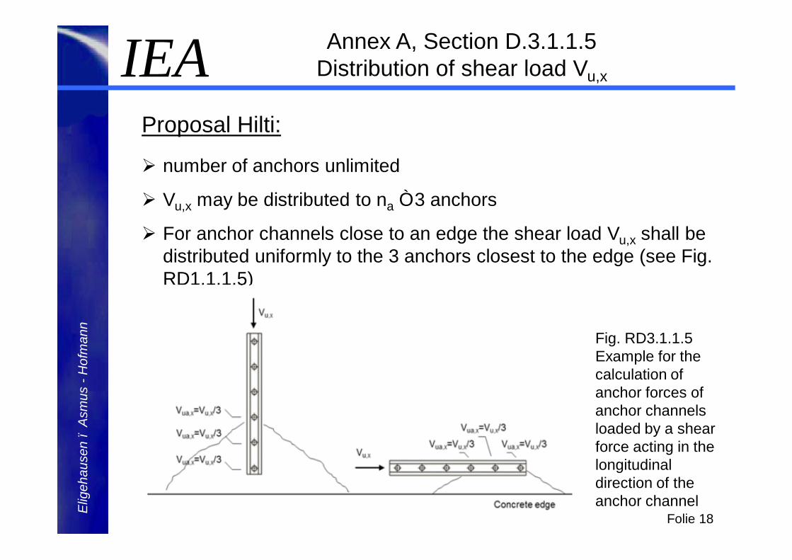
Proposal Hilti:
Ø number of anchors unlimited
Ø Vu,x may be distributed to na ≤ 3 anchors
Ø For anchor channels close to an edge the shear load Vu,x shall be distributed uniformly to the 3 anchors closest to the edge (see Fig. RD1.1.1.5)
Annex A, Section D.3.1.1.5 Distribution of shear load Vu,x
Fig. RD3.1.1.5 Example for the calculation of anchor forces of anchor channels loaded by a shear force acting in the longitudinal direction of the anchor channel
IEAE
ligeh
ause
n –
Asm
us -
Hof
man
n
Folie 19
Proposal IEA:
Ø Limit number of anchors on anchor channels to na ≤ 3, if Vu,x > 0
Ø Distribute Vu,x uniformly to the anchors
Reason for our proposal:The provisions for the distribution of Vu,x are not clear for anchor channels with many anchors.
Annex A, Section D.3.1.1.5 Distribution of shear load Vu,x
IEAE
ligeh
ause
n –
Asm
us -
Hof
man
n
Folie 20
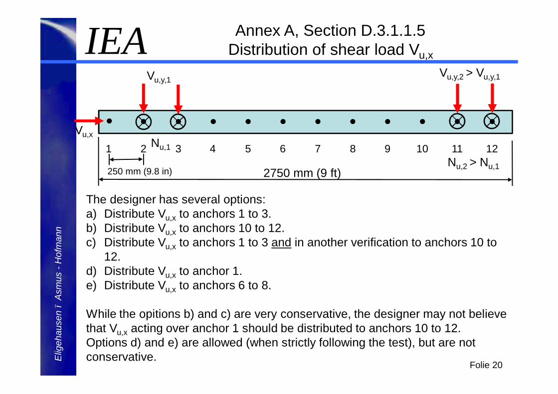
2750 mm (9 ft)
1 2 3 4 5 6 7 8 9 121110
250 mm (9.8 in)
Vu,x
Vu,y,1
Nu,1
Vu,y,2 > Vu,y,1
Nu,2 > Nu,1
Annex A, Section D.3.1.1.5 Distribution of shear load Vu,x
The designer has several options:a) Distribute Vu,x to anchors 1 to 3.b) Distribute Vu,x to anchors 10 to 12.c) Distribute Vu,x to anchors 1 to 3 and in another verification to anchors 10 to
12.d) Distribute Vu,x to anchor 1.e) Distribute Vu,x to anchors 6 to 8.
While the opitions b) and c) are very conservative, the designer may not believe that Vu,x acting over anchor 1 should be distributed to anchors 10 to 12. Options d) and e) are allowed (when strictly following the test), but are not conservative.
IEAE
ligeh
ause
n –
Asm
us -
Hof
man
n
Folie 21
Ø A more refined model for the distribution of Vu,x to the anchors of an anchor channel with many anchors is needed.
This model is not available yet.
Ø Therefore the number of anchors on an anchor channel should be limited to na ≤ 3 if Vu,x >0.
Ø Anchor channels with na ≤ 3 anchors cover about 90% of all applications.
Ø This approach has been used in Europe for a CEN Technical Report on the design of anchor channels loaded by longitudinal shear forces.
Annex A, Section D.3.1.1.5 Distribution of shear load Vu,x
IEAE
ligeh
ause
n –
Asm
us -
Hof
man
n
Folie 22
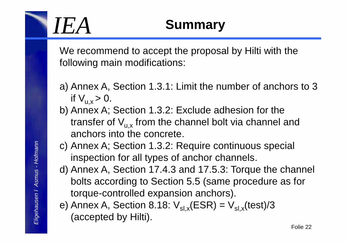
We recommend to accept the proposal by Hilti with the following main modifications:
a) Annex A, Section 1.3.1: Limit the number of anchors to 3 if Vu,x > 0.
b) Annex A; Section 1.3.2: Exclude adhesion for the transfer of Vu,x from the channel bolt via channel and anchors into the concrete.
c) Annex A; Section 1.3.2: Require continuous special inspection for all types of anchor channels.
d) Annex A, Section 17.4.3 and 17.5.3: Torque the channel bolts according to Section 5.5 (same procedure as for torque-controlled expansion anchors).
e) Annex A, Section 8.18: Vsl,x(ESR) = Vsl,x(test)/3 (accepted by Hilti).
Summary
IEAE
ligeh
ause
n –
Asm
us -
Hof
man
n
Folie 23
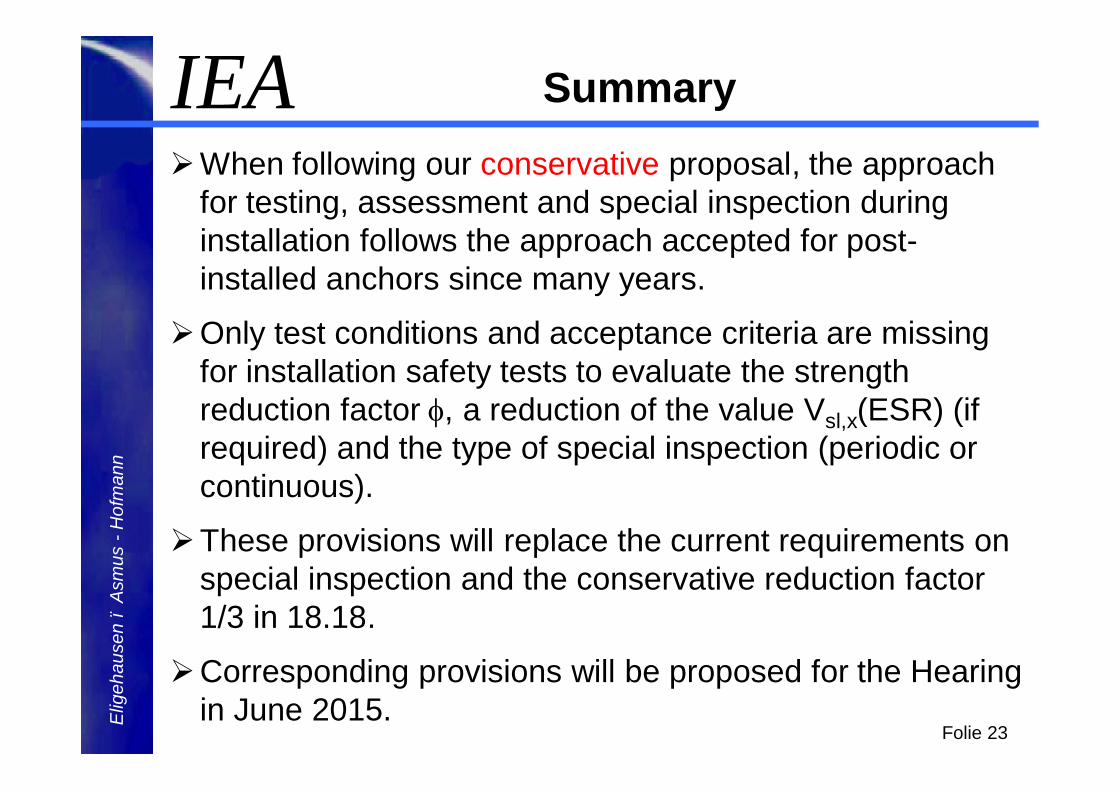
ØWhen following our conservative proposal, the approach for testing, assessment and special inspection during installation follows the approach accepted for post-installed anchors since many years.
ØOnly test conditions and acceptance criteria are missing for installation safety tests to evaluate the strength reduction factor φ, a reduction of the value Vsl,x(ESR) (if required) and the type of special inspection (periodic or continuous).
ØThese provisions will replace the current requirements on special inspection and the conservative reduction factor 1/3 in 18.18.
ØCorresponding provisions will be proposed for the Hearing in June 2015.
Summary

IEAE
ligeh
ause
n –
Asm
us -
Hof
man
n
Folie 24
Thank you for your attention.
Comments on Draft for Longitudinal Shear in AC 232
February 2015Florian Julier
AC232-0215-R1 #2
Content:
1. Scope definition
2. Special inspection requirements
3. Torque requirements for Anchor channel qualification
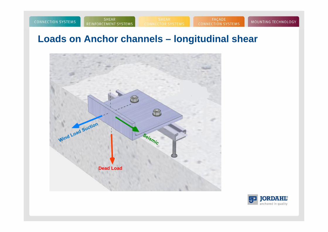
Loads on Anchor channels – longitudinal shear
Dead Load

Existing products in the market:
Toothed/Serrated ChannelsSmooth Channel combined with notching bolts
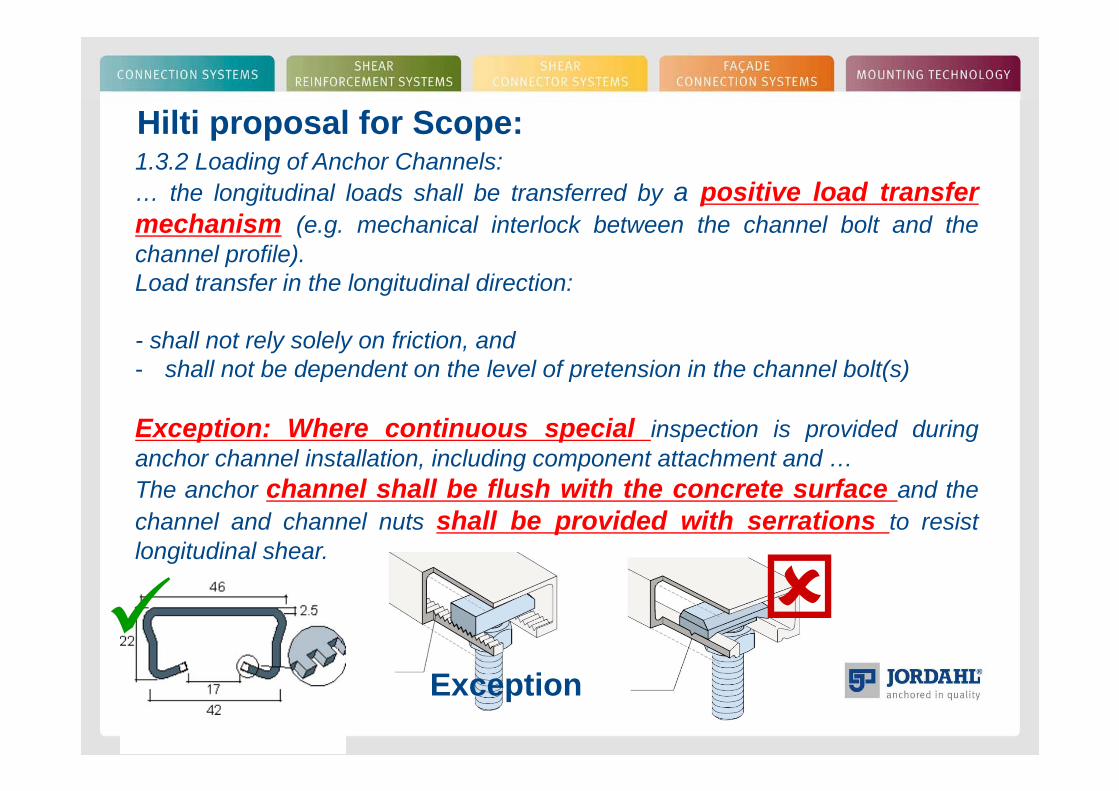
Hilti proposal for Scope:1.3.2 Loading of Anchor Channels:… the longitudinal loads shall be transferred by a positive load transfermechanism (e.g. mechanical interlock between the channel bolt and thechannel profile).Load transfer in the longitudinal direction:
- shall not rely solely on friction, and- shall not be dependent on the level of pretension in the channel bolt(s)
Exception: Where continuous special inspection is provided duringanchor channel installation, including component attachment and …The anchor channel shall be flush with the concrete surface and thechannel and channel nuts shall be provided with serrations to resistlongitudinal shear.
Exception
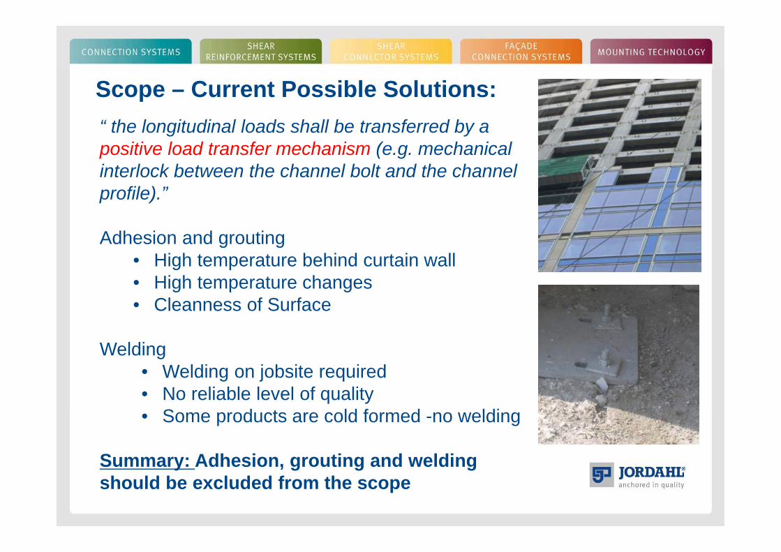
Scope – Current Possible Solutions:“ the longitudinal loads shall be transferred by a positive load transfer mechanism (e.g. mechanical interlock between the channel bolt and the channel profile).”
Adhesion and grouting• High temperature behind curtain wall• High temperature changes • Cleanness of Surface
Welding• Welding on jobsite required• No reliable level of quality• Some products are cold formed -no welding
Summary: Adhesion, grouting and welding should be excluded from the scope
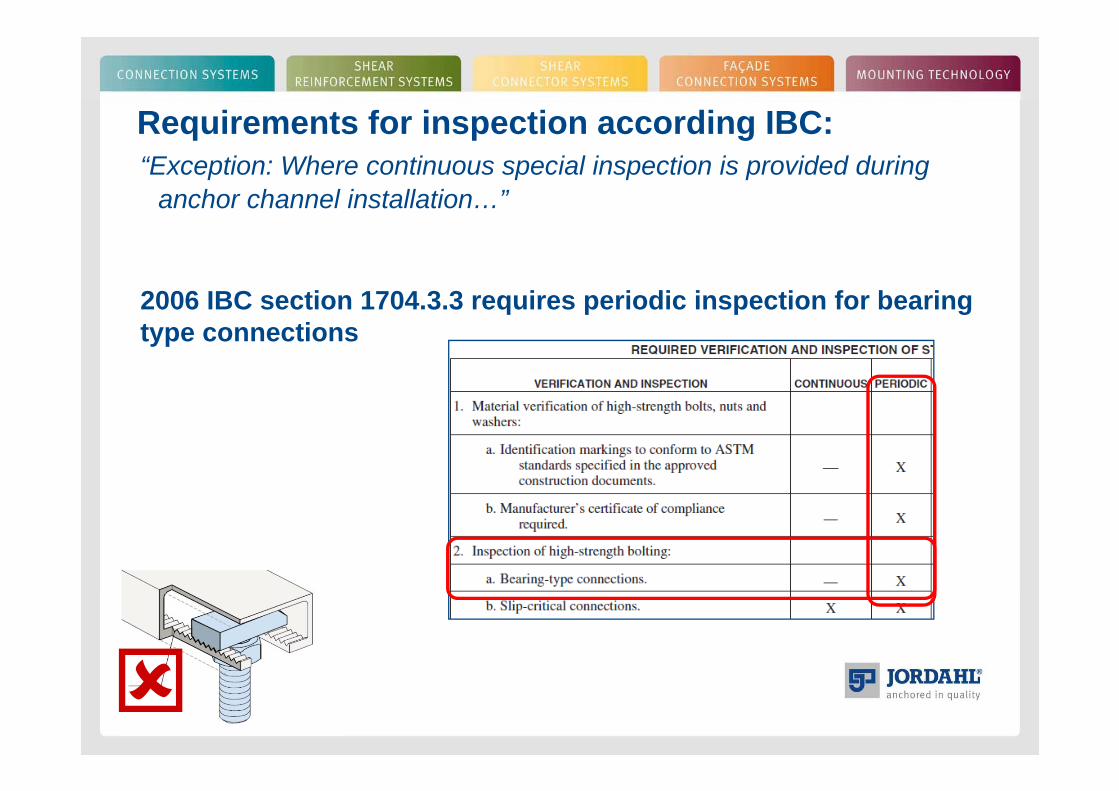
Requirements for inspection according IBC:“Exception: Where continuous special inspection is provided during
anchor channel installation…”
2006 IBC section 1704.3.3 requires periodic inspection for bearing type connections
Requirements for inspection - Proposal
“Exception: Where continuous special inspection is provided during anchor channel installation…”
IBC standard requires periodic inspection for bearing type connections
Proposal for a first & conservative step:
Delete the exception and require continuous inspection for all anchor channels with longitudinal loads in AC 232.
Installation Toques for Qualification–Hilti Proposal
7.14 Shear Tests on Anchor Channels Loaded in Longitudinal Channel Axis (Table 4.2, Test No. 15):
7.14.3 General test conditions: The tests shall be performed on anchor channels cast into concrete with two anchors located with the maximum anchor spacing and the distance between the end of the channel and the anchor axis to the minimum value specified by the manufacturer for the tested channel size. Place a PTFE layer (or other friction limiting material of similar friction coefficient) over the entire contact area between fixture and concrete surface. The channel bolt shall be inserted in the channel and pre-tensioned to a maximum of 20Nm (15ft-lb).
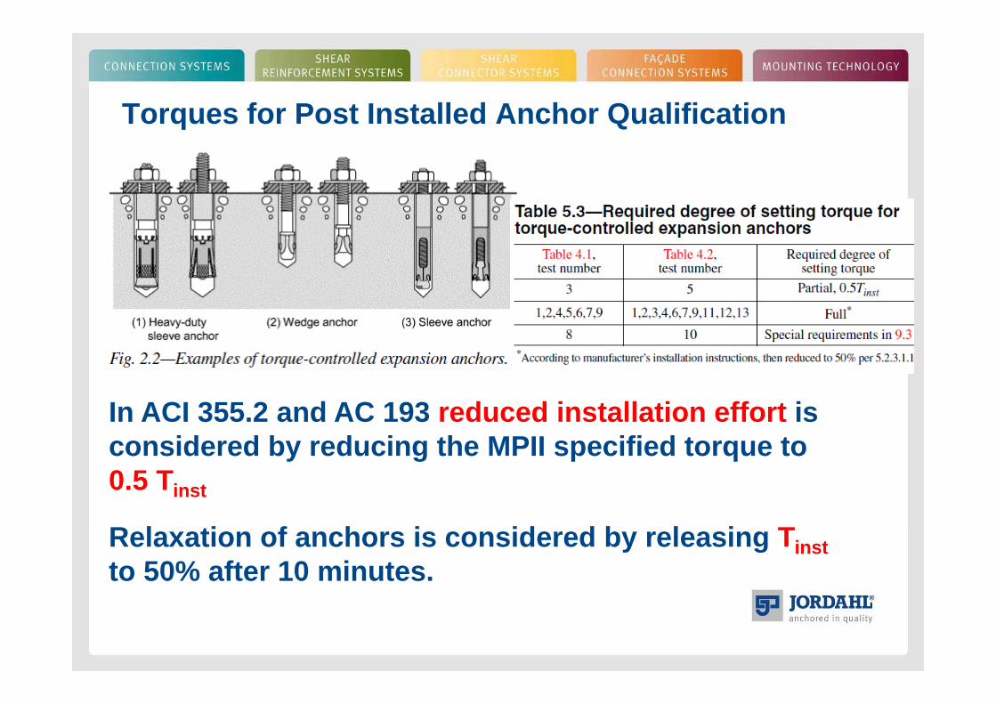
Torques for Post Installed Anchor Qualification
In ACI 355.2 and AC 193 reduced installation effort is considered by reducing the MPII specified torque to 0.5 Tinst
Relaxation of anchors is considered by releasing Tinstto 50% after 10 minutes.
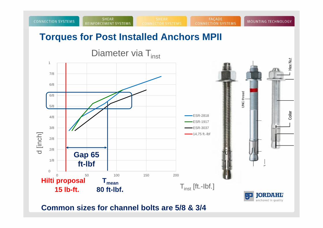
Torques for Post Installed Anchors MPII
0
1/8
2/8
2/8
3/8
4/8
5/8
6/8
6/8
7/8
1
0 50 100 150 200
d [in
ch]
Tinst [ft.-Ibf.]
Diameter via Tinst
ESR-2818
ESR-1917
ESR-3037
14,75 ft.-lbf.
Gap 65 ft-lbf
Hilti proposal Tmean15 lb-ft. 80 ft-lbf.
Common sizes for channel bolts are 5/8 & 3/4
Installation Toques for Post Installed Anchors
8.18 Assessment of the Steel Strength Under Shear Load Acting in Longitudinal Channel Axis (Test No. 15 in accordance with Table 4.2):
The measured failure loads shall be normalized according to Section 8.1.4 Eq. (8.3). The 5 percent-fractile of the normalized measured failure loads shall be computed by Eq (8.5). This value shall be multiplied with 0.5 and denoted as Vsl,x and reported in Section 9.5 of this annex.
Hilti proposal reduces nominal value by 0.5 to consider reduced installationeffort, which is conservative.
Additional limitation to a fixed value for very small torque is not in accordance with ACI and ICC codes for post installed anchors.
Summary
1. Scope should be defined – adhesion, grouting and welding excluded
2. Same inspection requirements for all products with longitudinal shear
3. Qualification and torques should follow AC 193 and ACI 355.2

Thank you very much for your attention!
Do you have any questions?