Embed Size (px)
Citation preview
350 East Plumeria DriveSan Jose, CA 95134USA
February 2016202-11624-02
ProSAFE Dual-Band Wireless AC Access Points WAC720 and WAC730Reference Manual
2
ProSAFE Dual-Band Wireless AC Access Points WAC720 and WAC730
SupportThank you for purchasing this NETGEAR product. You can visit www.netgear.com/support to register your product, get help, access the latest downloads and user manuals, and join our community. We recommend that you use only official NETGEAR support resources.
ConformityFor the current EU Declaration of Conformity, visit http://kb.netgear.com/app/answers/detail/a_id/11621.
ComplianceFor regulatory compliance information, visit http://www.netgear.com/about/regulatory.
See the regulatory compliance document before connecting the power supply.
Trademarks© NETGEAR, Inc., NETGEAR and the NETGEAR Logo are trademarks of NETGEAR, Inc. Any non-NETGEAR trademarks are used for reference purposes only.
Revision History
Publication Part Number Publish Date Comments
202-11624-02 February 2016 Revised Configure Wireless Bridging.
202-11624-01 December 2015 Revised Mount the Wireless Access Point.
202-11607-01 October 2015 First publication.
Contents
Chapter 1 Hardware Setup
Unpack Your Access Point . . . . . . . . . . . . . . . . . . . . . . . . . . . . . . . . . . . . . . . . . . . . . 7Hardware Description . . . . . . . . . . . . . . . . . . . . . . . . . . . . . . . . . . . . . . . . . . . . . . . . . 7
Top Panel . . . . . . . . . . . . . . . . . . . . . . . . . . . . . . . . . . . . . . . . . . . . . . . . . . . . . . . . . 7Rear Panel . . . . . . . . . . . . . . . . . . . . . . . . . . . . . . . . . . . . . . . . . . . . . . . . . . . . . . . . 8Bottom Panel With Product Label . . . . . . . . . . . . . . . . . . . . . . . . . . . . . . . . . . . . 9
Chapter 2 Initial Setup
What You Need Before You Begin . . . . . . . . . . . . . . . . . . . . . . . . . . . . . . . . . . . . . . 11System Requirements. . . . . . . . . . . . . . . . . . . . . . . . . . . . . . . . . . . . . . . . . . . . . . 11Wireless Equipment Placement and Range Guidelines . . . . . . . . . . . . . . . . . . 11Ethernet Cabling Requirements . . . . . . . . . . . . . . . . . . . . . . . . . . . . . . . . . . . . . 12LAN Configuration Requirements. . . . . . . . . . . . . . . . . . . . . . . . . . . . . . . . . . . . 12Hardware Requirements for Computers on Your LAN. . . . . . . . . . . . . . . . . . . 12Operating Frequency Guidelines. . . . . . . . . . . . . . . . . . . . . . . . . . . . . . . . . . . . . 12Requirements for Entering IP Addresses . . . . . . . . . . . . . . . . . . . . . . . . . . . . . . 13
Install and Configure the Wireless Access Point . . . . . . . . . . . . . . . . . . . . . . . . . . 13Connect the Wireless Access Point to a Computer . . . . . . . . . . . . . . . . . . . . . 14Log In to the Wireless Access Point . . . . . . . . . . . . . . . . . . . . . . . . . . . . . . . . . . 15Configure Basic General System Settings and Time Settings. . . . . . . . . . . . . 16Configure the IPv4 Settings . . . . . . . . . . . . . . . . . . . . . . . . . . . . . . . . . . . . . . . . 18Configure the Basic Wireless Settings . . . . . . . . . . . . . . . . . . . . . . . . . . . . . . . . 19
Test Basic Wireless Connectivity. . . . . . . . . . . . . . . . . . . . . . . . . . . . . . . . . . . . . . . 24Mount the Wireless Access Point . . . . . . . . . . . . . . . . . . . . . . . . . . . . . . . . . . . . . . 25
Package Content of the Ceiling and Wall Installation Kit. . . . . . . . . . . . . . . . . 25Drop Ceiling Installation . . . . . . . . . . . . . . . . . . . . . . . . . . . . . . . . . . . . . . . . . . . . 25Wall Installation . . . . . . . . . . . . . . . . . . . . . . . . . . . . . . . . . . . . . . . . . . . . . . . . . . . 28
Chapter 3 Wireless Configuration and Security
Wireless Data Security Options. . . . . . . . . . . . . . . . . . . . . . . . . . . . . . . . . . . . . . . . 32Security Profiles . . . . . . . . . . . . . . . . . . . . . . . . . . . . . . . . . . . . . . . . . . . . . . . . . . . . 33Configure and Enable Security Profiles . . . . . . . . . . . . . . . . . . . . . . . . . . . . . . . . . 35
Change the QoS Policy for a Wireless Security Profile . . . . . . . . . . . . . . . . . . 39Configure Legacy 802.1X . . . . . . . . . . . . . . . . . . . . . . . . . . . . . . . . . . . . . . . . . . 39Configure WPA With RADIUS and WPA & WPA2 With RADIUS . . . . . . . . . . . 39Configure WPA-PSK, WPA2-PSK, and WPA-PSK & WPA2-PSK . . . . . . . . . . 40
Configure RADIUS Server Settings. . . . . . . . . . . . . . . . . . . . . . . . . . . . . . . . . . . . . 41Restrict Wireless Access by MAC Address. . . . . . . . . . . . . . . . . . . . . . . . . . . . . . . 43Enable Rogue AP Detection . . . . . . . . . . . . . . . . . . . . . . . . . . . . . . . . . . . . . . . . . . . 44
3
ProSAFE Dual-Band Wireless AC Access Points WAC720 and WAC730
Schedule the Wireless Radios to Be Turned Off . . . . . . . . . . . . . . . . . . . . . . . . . . 46Configure Basic Wireless Quality of Service . . . . . . . . . . . . . . . . . . . . . . . . . . . . . 46
Chapter 4 Management and Monitoring
Enable Remote Management. . . . . . . . . . . . . . . . . . . . . . . . . . . . . . . . . . . . . . . . . . 49SNMP Management . . . . . . . . . . . . . . . . . . . . . . . . . . . . . . . . . . . . . . . . . . . . . . . 49Secure Shell and Telnet Management . . . . . . . . . . . . . . . . . . . . . . . . . . . . . . . . 50Manage the Wireless Access Point over a Telnet Connection . . . . . . . . . . . . 50
Upgrade the Wireless Access Point Software . . . . . . . . . . . . . . . . . . . . . . . . . . . . 51Upgrade the Firmware Over a Web Browser . . . . . . . . . . . . . . . . . . . . . . . . . . 52Upgrade the Firmware Over a TFTP Server . . . . . . . . . . . . . . . . . . . . . . . . . . . 53
Manage the Configuration File or Reset to Factory Defaults . . . . . . . . . . . . . . . 54Save the Configuration . . . . . . . . . . . . . . . . . . . . . . . . . . . . . . . . . . . . . . . . . . . . 54Restore the Configuration . . . . . . . . . . . . . . . . . . . . . . . . . . . . . . . . . . . . . . . . . . 55Restore the Wireless Access Point to the Factory Default Settings . . . . . . . 55Reboot the Wireless Access Point Without Restoring theDefault Configuration . . . . . . . . . . . . . . . . . . . . . . . . . . . . . . . . . . . . . . . . . . . . . 57
Change the Administrator Password . . . . . . . . . . . . . . . . . . . . . . . . . . . . . . . . . . . 57Manage User Accounts. . . . . . . . . . . . . . . . . . . . . . . . . . . . . . . . . . . . . . . . . . . . . . . 58
Add a New User Account . . . . . . . . . . . . . . . . . . . . . . . . . . . . . . . . . . . . . . . . . . . 58Change the Name for a User Account . . . . . . . . . . . . . . . . . . . . . . . . . . . . . . . . 59Change the Privilege for a User Account. . . . . . . . . . . . . . . . . . . . . . . . . . . . . . 59Reset the Password for a User Account. . . . . . . . . . . . . . . . . . . . . . . . . . . . . . . 60Delete a User Account . . . . . . . . . . . . . . . . . . . . . . . . . . . . . . . . . . . . . . . . . . . . . 60
Enable the Syslog Server . . . . . . . . . . . . . . . . . . . . . . . . . . . . . . . . . . . . . . . . . . . . . 61Monitor the Wireless Access Point . . . . . . . . . . . . . . . . . . . . . . . . . . . . . . . . . . . . . 61
View System Information . . . . . . . . . . . . . . . . . . . . . . . . . . . . . . . . . . . . . . . . . . 62Monitor Wireless Stations . . . . . . . . . . . . . . . . . . . . . . . . . . . . . . . . . . . . . . . . . . 64
View the Activity Log . . . . . . . . . . . . . . . . . . . . . . . . . . . . . . . . . . . . . . . . . . . . . . . . 66View the Traffic Statistics . . . . . . . . . . . . . . . . . . . . . . . . . . . . . . . . . . . . . . . . . . . . 67Enable and Configure Ensemble Mode. . . . . . . . . . . . . . . . . . . . . . . . . . . . . . . . . . 68
Configure Ensemble Mode . . . . . . . . . . . . . . . . . . . . . . . . . . . . . . . . . . . . . . . . . 69Manage an Ensemble . . . . . . . . . . . . . . . . . . . . . . . . . . . . . . . . . . . . . . . . . . . . . . 69Monitor an Ensemble . . . . . . . . . . . . . . . . . . . . . . . . . . . . . . . . . . . . . . . . . . . . . . 71
Chapter 5 Advanced Configuration
Configure IPv6 Settings . . . . . . . . . . . . . . . . . . . . . . . . . . . . . . . . . . . . . . . . . . . . . . 74Configure Spanning Tree Protocol, 802.1Q VLAN, andLink Layer Discovery Protocol . . . . . . . . . . . . . . . . . . . . . . . . . . . . . . . . . . . . . . . . . 75
Configure STP and VLANs . . . . . . . . . . . . . . . . . . . . . . . . . . . . . . . . . . . . . . . . . . 75Configure Ethernet LLDP. . . . . . . . . . . . . . . . . . . . . . . . . . . . . . . . . . . . . . . . . . . 77
Configure Bonjour . . . . . . . . . . . . . . . . . . . . . . . . . . . . . . . . . . . . . . . . . . . . . . . . . . . 78Configure Advanced Wireless Settings . . . . . . . . . . . . . . . . . . . . . . . . . . . . . . . . . 78Configure Advanced Quality of Service Settings . . . . . . . . . . . . . . . . . . . . . . . . . 81Configure and Manage Quality of Service Policies . . . . . . . . . . . . . . . . . . . . . . . 83
Configure a New QoS Policy . . . . . . . . . . . . . . . . . . . . . . . . . . . . . . . . . . . . . . . . 84Modify a QoS Policy . . . . . . . . . . . . . . . . . . . . . . . . . . . . . . . . . . . . . . . . . . . . . . . 88
4
ProSAFE Dual-Band Wireless AC Access Points WAC720 and WAC730
Delete a QoS Policy . . . . . . . . . . . . . . . . . . . . . . . . . . . . . . . . . . . . . . . . . . . . . . . 88Manage a Captive Portal . . . . . . . . . . . . . . . . . . . . . . . . . . . . . . . . . . . . . . . . . . . . . 89
Configure a Captive Portal . . . . . . . . . . . . . . . . . . . . . . . . . . . . . . . . . . . . . . . . . 89Add Users to a Captive Portal . . . . . . . . . . . . . . . . . . . . . . . . . . . . . . . . . . . . . . . 90Enable a Captive Portal . . . . . . . . . . . . . . . . . . . . . . . . . . . . . . . . . . . . . . . . . . . . 90
Configure Wireless Bridging. . . . . . . . . . . . . . . . . . . . . . . . . . . . . . . . . . . . . . . . . . . 91Point-to-Point Bridge and Point-to-Multipoint Bridge . . . . . . . . . . . . . . . . . 91Configure a Wireless Bridge . . . . . . . . . . . . . . . . . . . . . . . . . . . . . . . . . . . . . . . . 92
Chapter 6 Troubleshooting
Troubleshoot the Basic Functions . . . . . . . . . . . . . . . . . . . . . . . . . . . . . . . . . . . . . . 96Verify the Correct Sequence of Events at Startup . . . . . . . . . . . . . . . . . . . . . 96No LEDs Are Lit on the Wireless Access Point. . . . . . . . . . . . . . . . . . . . . . . . . . 96The Active LED or the LAN LED Is Not Lit . . . . . . . . . . . . . . . . . . . . . . . . . . . . . 97The WLAN LED Does Not Light. . . . . . . . . . . . . . . . . . . . . . . . . . . . . . . . . . . . . . 97
You Cannot Access the Internet or the LAN from aWireless-Capable Computer . . . . . . . . . . . . . . . . . . . . . . . . . . . . . . . . . . . . . . . . . . 97You Cannot Configure the Wireless Access Point from a Browser. . . . . . . . . . . 98When You Enter a URL or IP Address a Time-Out Error Occurs . . . . . . . . . . . . . 99Troubleshoot a TCP/IP Network Using the Ping Utility . . . . . . . . . . . . . . . . . . . . 99
Test the LAN Path to Your Wireless Access Point . . . . . . . . . . . . . . . . . . . . . . . 99Test the Path from Your Computer to a Remote Device . . . . . . . . . . . . . . . . 100
Problems With Date and Time . . . . . . . . . . . . . . . . . . . . . . . . . . . . . . . . . . . . . . . . 101Use the Packet Capture Tool . . . . . . . . . . . . . . . . . . . . . . . . . . . . . . . . . . . . . . . . . 101
Appendix A Supplemental Information
Technical Specifications . . . . . . . . . . . . . . . . . . . . . . . . . . . . . . . . . . . . . . . . . . . . . 103Factory Default Settings . . . . . . . . . . . . . . . . . . . . . . . . . . . . . . . . . . . . . . . . . . . . 105
5
1
1. Hardware SetupThis chapter covers the following topics:
• Unpack Your Access Point• Hardware Description
Note: For more information about the topics covered in this manual, visit the support website at support.netgear.com.
Note: Firmware updates with new features and bug fixes are made available from time to time at downloadcenter.netgear.com. Some products can regularly check the site and download new firmware, or you can check for and download new firmware manually. If the features or behavior of your product does not match what is described in this guide, you might need to update your firmware.
6
ProSAFE Dual-Band Wireless AC Access Points WAC720 and WAC730
Unpack Your Access Point
Your package contains the following items:
• ProSAFE Dual-Band Wireless AC Access Point• Straight-through Category 5 Ethernet cable• Ceiling and wall installation kit• Installation guide
Contact your reseller or customer support in your area if any parts are missing or damaged.
Visit the NETGEAR website at support.netgear.com/general/contact/default.aspx for the telephone number of customer support in your area.
Hardware Description
The following sections describe the top and rear hardware functions of the wireless access point.
• Top Panel• Rear Panel• Bottom Panel With Product Label
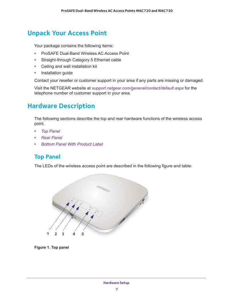
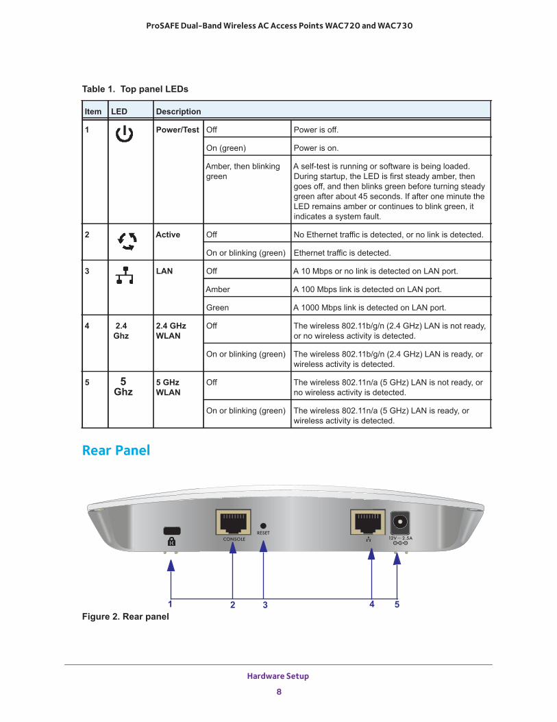
Top PanelThe LEDs of the wireless access point are described in the following figure and table:
Figure 1. Top panel
1 2 3 4 5
Hardware Setup
7
ProSAFE Dual-Band Wireless AC Access Points WAC720 and WAC730
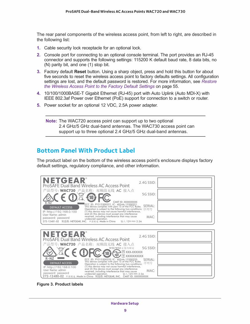
Rear Panel
Figure 2. Rear panel
Table 1. Top panel LEDs
Item LED Description
1 Power/Test Off Power is off.
On (green) Power is on.
Amber, then blinking green
A self-test is running or software is being loaded. During startup, the LED is first steady amber, then goes off, and then blinks green before turning steady green after about 45 seconds. If after one minute the LED remains amber or continues to blink green, it indicates a system fault.
2 Active Off No Ethernet traffic is detected, or no link is detected.
On or blinking (green) Ethernet traffic is detected.
3 LAN Off A 10 Mbps or no link is detected on LAN port.
Amber A 100 Mbps link is detected on LAN port.
Green A 1000 Mbps link is detected on LAN port.
4 2.4 Ghz
2.4 GHz WLAN
Off The wireless 802.11b/g/n (2.4 GHz) LAN is not ready, or no wireless activity is detected.
On or blinking (green) The wireless 802.11b/g/n (2.4 GHz) LAN is ready, or wireless activity is detected.
5 5 Ghz
5 GHz WLAN
Off The wireless 802.11n/a (5 GHz) LAN is not ready, or no wireless activity is detected.
On or blinking (green) The wireless 802.11n/a (5 GHz) LAN is ready, or wireless activity is detected.
1 2 3 54
Hardware Setup
8
ProSAFE Dual-Band Wireless AC Access Points WAC720 and WAC730
The rear panel components of the wireless access point, from left to right, are described in the following list:
1. Cable security lock receptacle for an optional lock.2. Console port for connecting to an optional console terminal. The port provides an RJ-45
connector and supports the following settings: 115200 K default baud rate, 8 data bits, no (N) parity bit, and one (1) stop bit.
3. Factory default Reset button. Using a sharp object, press and hold this button for about five seconds to reset the wireless access point to factory defaults settings. All configuration settings are lost, and the default password is restored. For more information, see Restore the Wireless Access Point to the Factory Default Settings on page 55.
4. 10/100/1000BASE-T Gigabit Ethernet (RJ-45) port with Auto Uplink (Auto MDI-X) with IEEE 802.3af Power over Ethernet (PoE) support for connection to a switch or router.
5. Power socket for an optional 12 VDC, 2.5A power adapter.
Note: The WAC720 access point can support up to two optional 2.4 GHz/5 GHz dual-band antennas. The WAC730 access point can support up to three optional 2.4 GHz/5 GHz dual-band antennas.
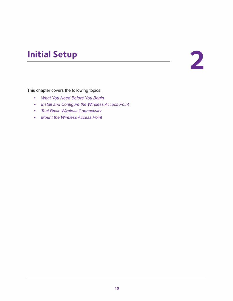
Bottom Panel With Product LabelThe product label on the bottom of the wireless access point’s enclosure displays factory default settings, regulatory compliance, and other information.
Figure 3. Product labels
: 12V 2.5A272-12481-02 制造商: NETGEAR, INC.
FCC ID: PY315300321 IC: 4054A-15300321This device complies with part 15 of the FCC Rules. Operation is subject to the following two conditions: (1) this device may not cause harmful interference, and (2) this device must accept any interference received, including interference that may cause undesired operation.
Made in China
CMIIT ID: XXXXXXXXXX
产品型号: WAC730 AC
序列号
: 12V 2.5A272-12480-02
FCC ID: PY315300320 IC: 4054A-15300320This device complies with part 15 of the FCC Rules. Operation is subject to the following two conditions: (1) this device may not cause harmful interference, and (2) this device must accept any interference received, including interference that may cause undesired operation.
Made in China CMIIT ID: XXXXXXXXXX
产品型号: WAC720 AC
序列号
XXX-XXXXXXXXXXXXXXXX
W52/W53
制造商: NETGEAR, INC.
Hardware Setup
9
2
2. Initial SetupThis chapter covers the following topics:
• What You Need Before You Begin • Install and Configure the Wireless Access Point• Test Basic Wireless Connectivity• Mount the Wireless Access Point
10
ProSAFE Dual-Band Wireless AC Access Points WAC720 and WAC730
What You Need Before You Begin
You must consider the following guidelines and requirements before you can set up your wireless access point.
System RequirementsBefore installing the access point, make sure that your system includes the following:
• A 10/100/1000 Mbps local area network device such as a hub or switch• The Category 5 UTP straight-through Ethernet cable with RJ-45 connector included in the
package, or one like it• A PoE switch or a 12V, 2.5 A, DC power source• A web browser for configuration• At least one computer with the TCP/IP protocol installed• 802.11bg/ng/bgn-compliant or 802.11a/a-na-ac-compliant devices
Wireless Equipment Placement and Range GuidelinesThe range of your wireless connection can vary significantly based on the location of the wireless access point. The latency, data throughput performance, and power consumption of wireless adapters also vary depending on your configuration choices.
Note: Failure to follow these guidelines can result in significant performance degradation or inability to connect wirelessly to the wireless access point. For complete performance specifications, see Appendix A, Supplemental Information.
Note: Before you position and mount the wireless access point at its permanent position, first configure the wireless access point and test the computers on your LAN for wireless connectivity as explained in this chapter.
For best results, place your wireless access point according to the following general guidelines:
• Near the center of the area in which the wireless devices will operate.• In an elevated location such as a high shelf where the wirelessly connected devices are
in a line-of-sight (even if through walls).• Away from sources of interference, such as computers, microwaves ovens, and 2.4 GHz
cordless phones.
Initial Setup
11
ProSAFE Dual-Band Wireless AC Access Points WAC720 and WAC730
• Away from large metal surfaces or water.• Placing an external antenna in a vertical position provides best side-to-side coverage.
Placing an external antenna in a horizontal position provides best up-and-down coverage. (An external antenna does not come standard with the wireless access point.)
If you are using multiple wireless access points, it is better if adjacent wireless access points use different radio frequency channels to reduce interference. The recommended channel spacing between adjacent wireless access points is five channels (for example, use Channels 1 and 6, or 6 and 11, or 1 and 11).
The time it takes to establish a wireless connection can vary depending on both your security settings and placement.
Ethernet Cabling RequirementsThe wireless access point connects to your LAN using twisted-pair Category 5 Ethernet cable with RJ-45 connectors.
LAN Configuration RequirementsFor the initial configuration of your wireless access point, you must connect a computer to the wireless access point.
Hardware Requirements for Computers on Your LANTo connect to the wireless access point on your network, an 802.11bg/ng/bgn or 802.11a/a-na-ac wireless adapter must be installed on each computer. We recommend using the wireless access point with computers with the NETGEAR A6210 WiFi USB Adapter installed.
Operating Frequency GuidelinesYou do not need to change the operating frequency (channel) unless you notice interference problems or you place the wireless access point near another wireless access point. If you do change the operating frequency, observe the following guidelines:
• Wireless access points use a fixed channel. You can select a channel that provides the least interference and best performance. In the United States and Canada, 11 channels are available.
• If you use multiple wireless access points, it is better if adjacent wireless access points use different channels to reduce interference. The recommended channel spacing between adjacent wireless access points is five channels (for example, use Channels 1 and 6, or 6 and 11).
• In infrastructure mode (which is the default mode for the wireless access point), wireless stations normally scan all channels, looking for a wireless access point. If more than one wireless access point can be used, the one with the strongest signal is used. This is possible only if the wireless access points use the same SSID.
Initial Setup
12
ProSAFE Dual-Band Wireless AC Access Points WAC720 and WAC730
Requirements for Entering IP AddressesIP addresses assigned to the access points must follow the following requirements for IPv4 and IPv6 addresses.
IPv4The fourth octet of an IP address must be between 0 and 255 (both inclusive). This requirement applies to any IP address that you enter on the wireless access point’s web management interface.
IPv6IPv6 addresses are denoted by eight groups of hexadecimal quartets that are separated by colons. Any four-digit group of zeroes within an IPv6 address can be reduced to a single zero or altogether omitted.
The following errors invalidate an IPv6 address:
• More than eight groups of hexadecimal quartets• More than four hexadecimal characters in a quartet• More than two colons in a row
Install and Configure the Wireless Access Point
Install and configure your wireless access point in the order of the following sections:
1. Connect the Wireless Access Point to a Computer2. Log In to the Wireless Access Point3. Configure Basic General System Settings and Time Settings4. Configure the IPv4 Settings5. Configure the Basic Wireless Settings
Before installing the wireless access point, make sure that your Ethernet network functions. After you connect the wireless access point to the Ethernet network, computers with 802.11b/g/a/n/ac wireless adapters are able to communicate with the Ethernet network.
For this to work correctly, verify that you meet all the system requirements, shown in Hardware Description on page 7.
Initial Setup
13
ProSAFE Dual-Band Wireless AC Access Points WAC720 and WAC730
Connect the Wireless Access Point to a Computer
Tip: Before you place the wireless access point in an elevated position that is difficult to reach, first set up and test the wireless access point to verify wireless network connectivity.
To set up the wireless access point:
1. Unpack the box and verify the contents.2. Prepare a computer with an Ethernet adapter.
If this computer is already part of your network, record its TCP/IP configuration settings. Configure the computer with a static IP address of 192.168.0.210 and 255.255.255.0 as the subnet mask.
3. Connect an Ethernet cable from the wireless access point to the computer.4. Securely insert the other end of the cable into the wireless access point’s Ethernet port.5. Turn on your computer.6. Connect the wireless access point to a PoE switch or power adapter.
Tip: The wireless access point supports Power over Ethernet (PoE) with power redundancy. If you are using a switch that provides PoE, you do not need to use a power adapter to power the wireless access point. Using PoE can be especially convenient when the wireless access point is installed in a high location far away from a power outlet.
7. Verify the following:
Power/Test LED. The Power/Test LED blinks when the wireless access point is first turned on. (To be exact, during startup, the LED is first steady amber, then goes off, and then blinks green.) After about 45 seconds, the LED stays lit
(steady green). If after one minute the Power/Test LED is not lit or is still blinking, check the connections and see if the power outlet is controlled by a wall switch that is turned off.
Active LED. The Active LED is lit or blinks green when Ethernet traffic is detected.
LAN LED. The LAN LED indicates the LAN speed for LAN port 1: green for 1000 Mbps, amber for 100 Mbps, and no light for 10 Mbps. If the LAN LED is not lit, make sure that the Ethernet cable is securely attached at both ends.
2.4 GHz WLAN LED. The 2.4 GHz WLAN LED is lit or blinks green when the wireless LAN (WLAN) is ready.
5 GHz WLAN LED. The 5 GHz WLAN LED is lit or blinks green when the wireless LAN (WLAN) is ready.
2.4Ghz
5Ghz
Initial Setup
14
ProSAFE Dual-Band Wireless AC Access Points WAC720 and WAC730
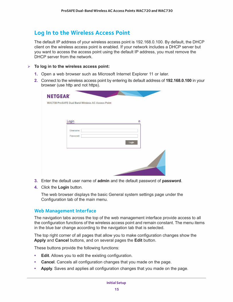
Log In to the Wireless Access PointThe default IP address of your wireless access point is 192.168.0.100. By default, the DHCP client on the wireless access point is enabled. If your network includes a DHCP server but you want to access the access point using the default IP address, you must remove the DHCP server from the network.
To log in to the wireless access point:
1. Open a web browser such as Microsoft Internet Explorer 11 or later. 2. Connect to the wireless access point by entering its default address of 192.168.0.100 in your
browser (use http and not https).
3. Enter the default user name of admin and the default password of password.4. Click the Login button.
The web browser displays the basic General system settings page under the Configuration tab of the main menu.
Web Management InterfaceThe navigation tabs across the top of the web management interface provide access to all the configuration functions of the wireless access point and remain constant. The menu items in the blue bar change according to the navigation tab that is selected.
The top right corner of all pages that allow you to make configuration changes show the Apply and Cancel buttons, and on several pages the Edit button.
These buttons provide the following functions:
• Edit. Allows you to edit the existing configuration.• Cancel. Cancels all configuration changes that you made on the page.• Apply. Saves and applies all configuration changes that you made on the page.
Initial Setup
15
ProSAFE Dual-Band Wireless AC Access Points WAC720 and WAC730
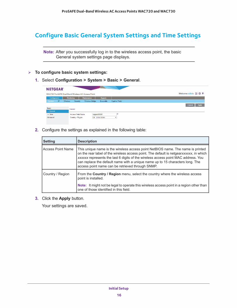
Configure Basic General System Settings and Time Settings
Note: After you successfully log in to the wireless access point, the basic General system settings page displays.
To configure basic system settings:
1. Select Configuration > System > Basic > General.
2. Configure the settings as explained in the following table:
3. Click the Apply button.
Your settings are saved.
Setting Description
Access Point Name This unique name is the wireless access point NetBIOS name. The name is printed on the rear label of the wireless access point. The default is netgearxxxxxx, in which xxxxxx represents the last 6 digits of the wireless access point MAC address. You can replace the default name with a unique name up to 15 characters long. The access point name can be retrieved through SNMP.
Country / Region From the Country / Region menu, select the country where the wireless access point is installed.
Note: It might not be legal to operate this wireless access point in a region other than one of those identified in this field.
Initial Setup
16
ProSAFE Dual-Band Wireless AC Access Points WAC720 and WAC730
To configure time settings:
1. Select Configuration > System > Basic > Time.
2. Configure the settings as explained in the following table:
3. Click the Apply button.
Your settings are saved.
Setting Description
Time Zone Select the time zone to match your location.
Current Time This is a nonconfigurable field that displays the current date and time.
NTP Client Enable the Network Time Protocol (NTP) client to synchronize the time of the wireless access point with an NTP server. By default the Enable radio button is selected.
Use Custom NTP Server Select this check box if you want to use a custom NTP server.
Note: You need an Internet connection to use an NTP server that is not on your local network.
Hostname / IP Address
Enter the host name or IP address of the custom NTP server. The default is time-b.netgear.com.
Note: If you use a host name, make sure that you configured a DNS server.
Initial Setup
17
ProSAFE Dual-Band Wireless AC Access Points WAC720 and WAC730
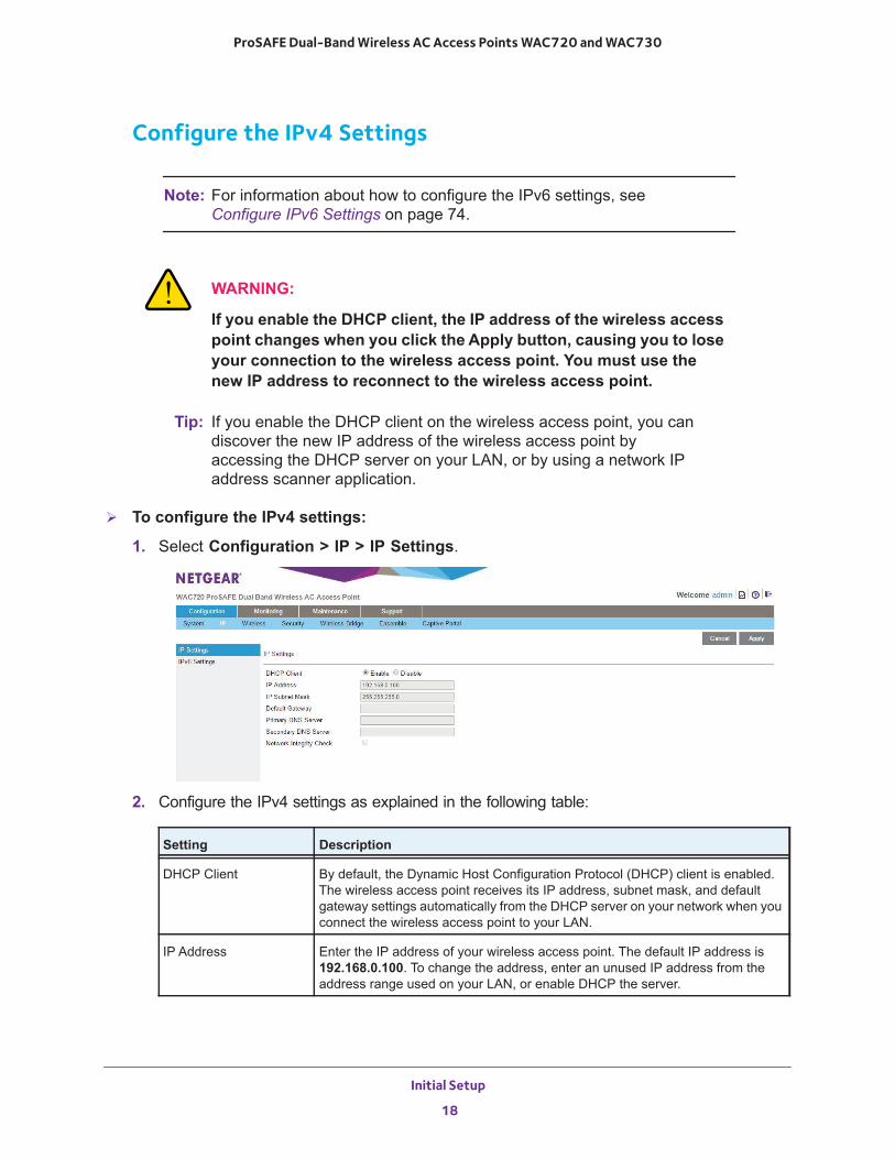
Configure the IPv4 Settings
Note: For information about how to configure the IPv6 settings, see Configure IPv6 Settings on page 74.
WARNING:
If you enable the DHCP client, the IP address of the wireless access point changes when you click the Apply button, causing you to lose your connection to the wireless access point. You must use the new IP address to reconnect to the wireless access point.
Tip: If you enable the DHCP client on the wireless access point, you can discover the new IP address of the wireless access point by accessing the DHCP server on your LAN, or by using a network IP address scanner application.
To configure the IPv4 settings:
1. Select Configuration > IP > IP Settings.
2. Configure the IPv4 settings as explained in the following table:
Setting Description
DHCP Client By default, the Dynamic Host Configuration Protocol (DHCP) client is enabled. The wireless access point receives its IP address, subnet mask, and default gateway settings automatically from the DHCP server on your network when you connect the wireless access point to your LAN.
IP Address Enter the IP address of your wireless access point. The default IP address is 192.168.0.100. To change the address, enter an unused IP address from the address range used on your LAN, or enable DHCP the server.
Initial Setup
18
ProSAFE Dual-Band Wireless AC Access Points WAC720 and WAC730
3. Click the Apply button.
Your settings are saved.
Configure the Basic Wireless SettingsFor proper compliance and compatibility between similar products in your coverage area, you must configure the 802.11bg/ng/bgn and 802.11a/a-na-ac wireless adapter settings correctly, including the operating channel and country. You also must configure the basic wireless network settings for wireless devices to connect to your network. For other wireless features, including wireless security, see Chapter 3, Wireless Configuration and Security.
WARNING:
If you configure the wireless access point from a wireless computer and you change the wireless access point’s SSID, channel, or wireless security settings, you lose your wireless connection when you click the Apply button. You then must change the wireless settings of your computer to match the wireless access point’s new settings.
IP Subnet Mask Enter the network number portion of an IP address. Unless you are implementing subnetting, enter 255.255.0.0 as the subnet mask.
Default Gateway Enter the IP address of the ISP gateway to which the wireless access point connects.
Primary DNS Server Enter the IP address of the primary and secondary DNS servers. A DNS server is a host on the Internet that translates Internet names (such as www.netgear.com) to numeric IP addresses. Typically your ISP transfers the IP address of one or two DNS servers to your wireless access point during login. If the ISP does not transfer an address, you must obtain it from the ISP and enter it manually in this field.
Secondary DNS Server
Network Integrity Check Select this check box to validate that the upstream link is active before allowing wireless associations. Ensure that the default gateway is configured.
Setting Description
Initial Setup
19
ProSAFE Dual-Band Wireless AC Access Points WAC720 and WAC730
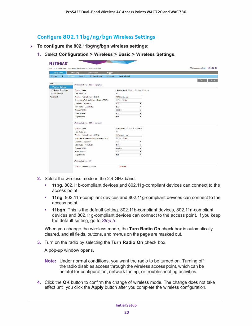
Configure 802.11bg/ng/bgn Wireless Settings
To configure the 802.11bg/ng/bgn wireless settings:
1. Select Configuration > Wireless > Basic > Wireless Settings.
2. Select the wireless mode in the 2.4 GHz band:• 11bg. 802.11b-compliant devices and 802.11g-compliant devices can connect to the
access point.• 11ng. 802.11n-compliant devices and 802.11g-compliant devices can connect to the
access point• 11bgn. This is the default setting. 802.11b-compliant devices, 802.11n-compliant
devices and 802.11g-compliant devices can connect to the access point. If you keep the default setting, go to Step 5.
When you change the wireless mode, the Turn Radio On check box is automatically cleared, and all fields, buttons, and menus on the page are masked out.
3. Turn on the radio by selecting the Turn Radio On check box.
A pop-up window opens.
Note: Under normal conditions, you want the radio to be turned on. Turning off the radio disables access through the wireless access point, which can be helpful for configuration, network tuning, or troubleshooting activities.
4. Click the OK button to confirm the change of wireless mode. The change does not take effect until you click the Apply button after you complete the wireless configuration.
Initial Setup
20
ProSAFE Dual-Band Wireless AC Access Points WAC720 and WAC730
5. Specify the remaining wireless settings as explained the following table:
6. Click the Apply button.
Your settings are saved.
Setting Descriptions
Wireless Network Name (SSID)
Enter a 32-character (maximum) service set identifier (SSID); the characters are case-sensitive. The default is NETGEAR_11ng. The SSID assigned to a wireless device must match the wireless access point’s SSID for the wireless device to communicate with the wireless access point. If the SSIDs do not match, you do not get a wireless connection to the wireless access point.
Broadcast Wireless Network Name (SSID)
Select the Yes radio button to enable the wireless access point to broadcast its SSID, allowing wireless stations with a null (blank) SSID to adopt the wireless access point’s SSID. Yes is the default setting. To prevent the SSID from being broadcast, select the No radio button.
Channel / Frequency From the menu, select the channel you want to use for your wireless LAN. The wireless channels and frequencies depend on the country and wireless mode. The default setting is Auto.
Note: You do not need to change the wireless channel unless you experience interference (indicated by lost connections or slow data transfers). If this happens, you might want to experiment with different channels to see which is the best. For more information, see Operating Frequency Guidelines on page 12.
Note: For more information about available channels and frequencies, see Technical Specifications on page 103.
11ng and 11bgn modes only
Note: For most networks, the default settings work fine.
MCS Index / Data Rate
From the menu, select a Modulation and Coding Scheme (MCS) index and transmit data rate for the wireless network. The default setting is Best. For a list of all options that you can select from in 11ng and 11bgn modes, see Factory Default Settings on page 105.
Channel Width From the menu, select a channel width. The options are 20 MHz and 40 MHz. The default is 40 MHz.
Guard Interval From the menu, select the guard interval to protect transmissions from interference. The default is Auto, or you can select Long - 800 ns. Some legacy devices can operate only with a long guard interval.
11bg modes only Data Rate From the menu, select the transmit data rate of the wireless network. The default setting is Best. For a list of all options that you can select from in 11bg mode, see Factory Default Settings on page 105.
Output Power From the menu, select the transmission power of the wireless access point: Full, Half, Quarter, Eighth, Minimum. The default is Full.
Note: Increasing the power improves performance, but if two or more wireless access points are operating in the same area and on the same channel, interference can occur.
Note: Make sure that you comply with the regulatory requirements for total radio frequency (RF) output power in your country.
Initial Setup
21
ProSAFE Dual-Band Wireless AC Access Points WAC720 and WAC730
Note: For information about how to configure advanced wireless settings, see Configure Advanced Wireless Settings on page 78.
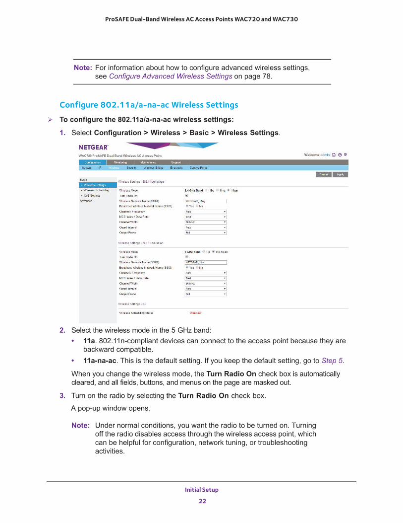
Configure 802.11a/a-na-ac Wireless Settings
To configure the 802.11a/a-na-ac wireless settings:
1. Select Configuration > Wireless > Basic > Wireless Settings.
2. Select the wireless mode in the 5 GHz band:• 11a. 802.11n-compliant devices can connect to the access point because they are
backward compatible.• 11a-na-ac. This is the default setting. If you keep the default setting, go to Step 5.
When you change the wireless mode, the Turn Radio On check box is automatically cleared, and all fields, buttons, and menus on the page are masked out.
3. Turn on the radio by selecting the Turn Radio On check box.
A pop-up window opens.
Note: Under normal conditions, you want the radio to be turned on. Turning off the radio disables access through the wireless access point, which can be helpful for configuration, network tuning, or troubleshooting activities.
Initial Setup
22
ProSAFE Dual-Band Wireless AC Access Points WAC720 and WAC730
4. Click the OK button to confirm the change of wireless mode.
The change does not take effect until you click the Apply button after you complete the wireless configuration.
5. Specify the remaining wireless settings as explained the following table:
Setting Descriptions
Wireless Network Name (SSID)
Enter a 32-character (maximum) service set identifier (SSID); the characters are case-sensitive. The default is NETGEAR_11ac. The SSID assigned to a wireless device must match the wireless access point’s SSID for the wireless device to communicate with the wireless access point. If the SSIDs do not match, you do not get a wireless connection to the wireless access point.
Broadcast Wireless Network Name (SSID)
Select the Yes radio button to enable the wireless access point to broadcast its SSID, allowing wireless stations with a null (blank) SSID to adopt the wireless access point’s SSID. Yes is the default setting. To prevent the SSID from being broadcast, select the No radio button.
Channel / Frequency From the menu, select the channel you wish to use on your wireless LAN. The wireless channels and frequencies depend on the country and wireless mode. The default setting is Auto.
Note: You do not need to change the wireless channel unless you experience interference (indicated by lost connections or slow data transfers). If this happens, you might want to experiment with different channels to see which is the best. For more information, see the guidelines following this table.
Note: For more information about available channels and frequencies, see Technical Specifications on page 103.
11a-na-ac mode only
Note: For most networks, the default settings work fine.
MCS Index / Data Rate
From the menu, select a Modulation and Coding Scheme (MCS) index and transmit data rate for the wireless network. The default setting is Best. For a list of all options that you can select from in 11a-na-ac mode, see Factory Default Settings on page 105.
Channel Width From the menu, select a channel width. The options are 20 MHz, 40 MHz, and 80 MHz. The default is 80 MHz.
Guard Interval From the menu, select the guard interval to protect transmissions from interference. The default is Auto, or you can select Long - 800 ns. Some legacy devices can operate only with a long guard interval.
Initial Setup
23
ProSAFE Dual-Band Wireless AC Access Points WAC720 and WAC730
6. Click the Apply button.
Your settings are saved.
Note: For information about how to configure advanced wireless settings, see Configure Advanced Wireless Settings on page 78.
Test Basic Wireless Connectivity
After you configure the wireless access point, test the computers on your LAN for wireless connectivity before you position and mount the wireless access point at its permanent position.
To test for wireless connectivity:
1. Configure the wireless adapters of your computers so that they all use the same SSID and channel that you configured on the wireless access point.
2. Verify that your computers acquired a wireless link to the wireless access point. 3. Verify network connectivity by using a browser such as Internet Explorer, Mozilla Firefox, or
Google Chrome to browse the Internet, or check for file and printer access on your network.
Note: If you experience trouble connecting to the wireless access point, see Chapter 6, Troubleshooting.
We recommend that you complete the following tasks before you deploy the wireless access point in your network:
• Configure wireless security and other wireless features as described in Chapter 3, Wireless Configuration and Security.
• Configure any additional features that you might need as described in Chapter 4, Management and Monitoring, and Chapter 5, Advanced Configuration.
11a mode only Data Rate From the menu, select the transmit data rate of the wireless network. The default setting is Best. For a list of all options that you can select from in 11a mode, see Factory Default Settings on page 105.
Output Power From the menu, select the transmission power of the wireless access point: Full, Half, Quarter, Eighth, Minimum. The default is Full.
Note: Increasing the power improves performance, but if two or more wireless access points are operating in the same area and on the same channel, interference can occur.
Note: Make sure that you comply with the regulatory requirements for total radio frequency (RF) output power in your country.
Setting Descriptions
Initial Setup
24
ProSAFE Dual-Band Wireless AC Access Points WAC720 and WAC730
After you complete the configuration of the wireless access point, you can reconfigure the computer that you used for this process back to its original TCP/IP settings.
Mount the Wireless Access Point
The following sections explain how to mount your wireless access point. We recommend that you review the information in Wireless Equipment Placement and Range Guidelines on page 11 before you mount the wireless access point at its permanent position.
• Package Content of the Ceiling and Wall Installation Kit• Drop Ceiling Installation• Wall Installation
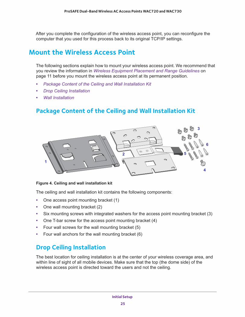
Package Content of the Ceiling and Wall Installation Kit
Figure 4. Ceiling and wall installation kit
The ceiling and wall installation kit contains the following components:
• One access point mounting bracket (1)• One wall mounting bracket (2)• Six mounting screws with integrated washers for the access point mounting bracket (3)• One T-bar screw for the access point mounting bracket (4)• Four wall screws for the wall mounting bracket (5)• Four wall anchors for the wall mounting bracket (6)
Drop Ceiling InstallationThe best location for ceiling installation is at the center of your wireless coverage area, and within line of sight of all mobile devices. Make sure that the top (the dome side) of the wireless access point is directed toward the users and not the ceiling.
1
2
3
5
6
4
Initial Setup
25
ProSAFE Dual-Band Wireless AC Access Points WAC720 and WAC730
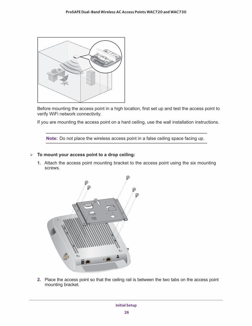
Before mounting the access point in a high location, first set up and test the access point to verify WiFi network connectivity.
If you are mounting the access point on a hard ceiling, use the wall installation instructions.
Note: Do not place the wireless access point in a false ceiling space facing up.
To mount your access point to a drop ceiling:
1. Attach the access point mounting bracket to the access point using the six mounting screws.
2. Place the access point so that the ceiling rail is between the two tabs on the access point mounting bracket.
Initial Setup
26
ProSAFE Dual-Band Wireless AC Access Points WAC720 and WAC730
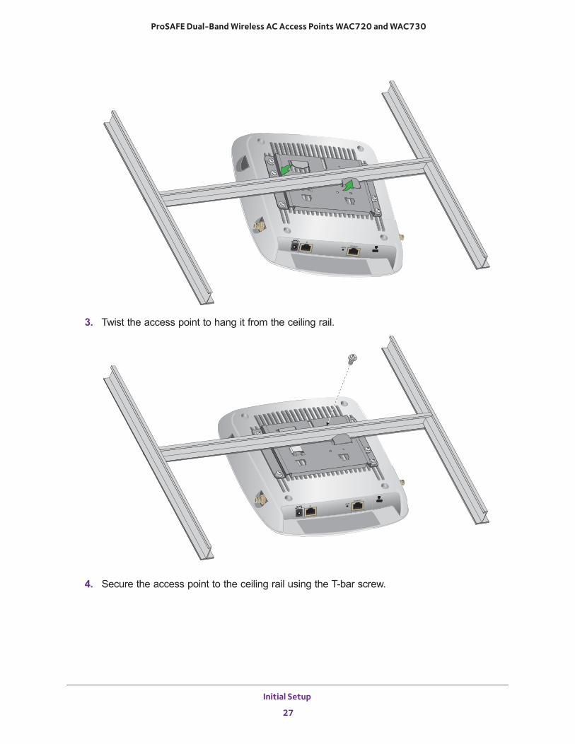
3. Twist the access point to hang it from the ceiling rail.
4. Secure the access point to the ceiling rail using the T-bar screw.
Initial Setup
27
ProSAFE Dual-Band Wireless AC Access Points WAC720 and WAC730
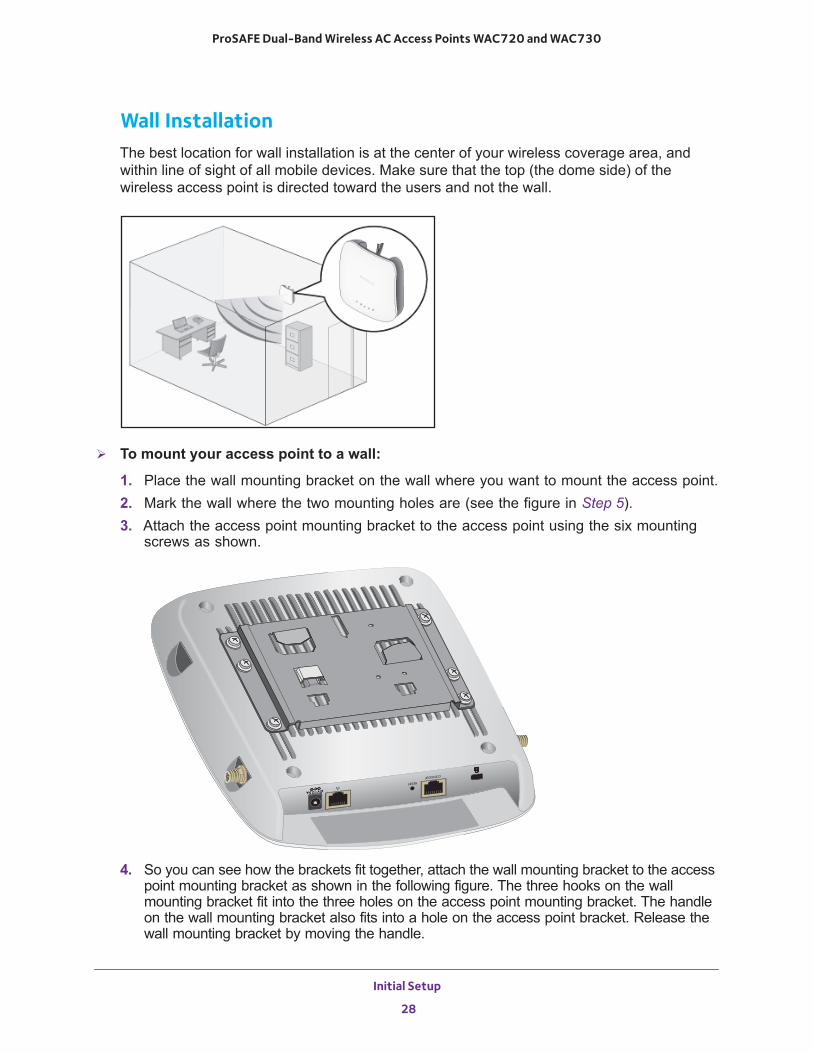
Wall InstallationThe best location for wall installation is at the center of your wireless coverage area, and within line of sight of all mobile devices. Make sure that the top (the dome side) of the wireless access point is directed toward the users and not the wall.
To mount your access point to a wall:
1. Place the wall mounting bracket on the wall where you want to mount the access point.2. Mark the wall where the two mounting holes are (see the figure in Step 5).3. Attach the access point mounting bracket to the access point using the six mounting
screws as shown.
4. So you can see how the brackets fit together, attach the wall mounting bracket to the access point mounting bracket as shown in the following figure. The three hooks on the wall mounting bracket fit into the three holes on the access point mounting bracket. The handle on the wall mounting bracket also fits into a hole on the access point bracket. Release the wall mounting bracket by moving the handle.
Initial Setup
28
ProSAFE Dual-Band Wireless AC Access Points WAC720 and WAC730
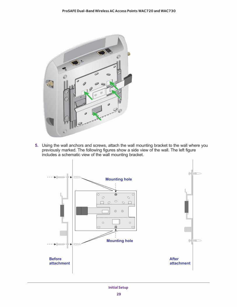
5. Using the wall anchors and screws, attach the wall mounting bracket to the wall where you previously marked. The following figures show a side view of the wall. The left figure includes a schematic view of the wall mounting bracket.
Mounting hole
Mounting hole
Beforeattachment
Afterattachment
Initial Setup
29
ProSAFE Dual-Band Wireless AC Access Points WAC720 and WAC730
Note: Although the product package includes four wall anchors and screws, two screws are sufficient to attach the wall mounting bracket as shown in the previous figure. However, if you prefer, you can use four screws and insert them through the mounting holes in the corners of the wall mounting bracket.
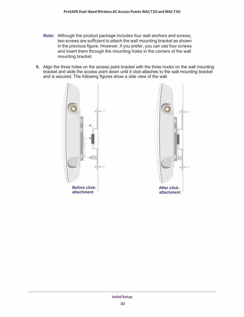
6. Align the three holes on the access point bracket with the three hooks on the wall mounting bracket and slide the access point down until it click-attaches to the wall mounting bracket and is secured. The following figures show a side view of the wall.
Before click-attachment
After click-attachment
Initial Setup
30
3
3. Wireless Configuration and SecurityThis chapter describes how to configure the wireless features of the wireless access point. The chapter includes the following sections:
• Wireless Data Security Options• Security Profiles• Configure and Enable Security Profiles• Configure RADIUS Server Settings• Restrict Wireless Access by MAC Address• Enable Rogue AP Detection• Schedule the Wireless Radios to Be Turned Off• Configure Basic Wireless Quality of Service
Before you set up wireless security and additional wireless features that are described in this chapter, connect the wireless access point, get the Internet connection working, and configure the 802.11bg/ng/bgn and 802.11a/a-na-ac wireless settings as described in Chapter 2, Initial Setup. The wireless access point functions with an Ethernet LAN connection. Make sure that you verify wireless connectivity before you set up wireless security and additional wireless features.
WARNING:
If you are configuring the wireless access point from a wireless computer and you change the wireless access point’s SSID, channel, or wireless security settings, you lose your wireless connection when you click the Apply button. You must then change the wireless settings of your computer to match the wireless access point’s new settings.
31
ProSAFE Dual-Band Wireless AC Access Points WAC720 and WAC730
Wireless Data Security Options
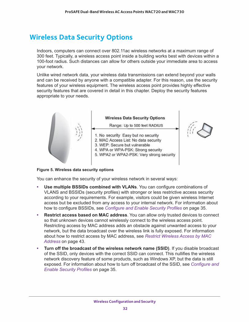
Indoors, computers can connect over 802.11ac wireless networks at a maximum range of 300 feet. Typically, a wireless access point inside a building works best with devices within a 100-foot radius. Such distances can allow for others outside your immediate area to access your network.
Unlike wired network data, your wireless data transmissions can extend beyond your walls and can be received by anyone with a compatible adapter. For this reason, use the security features of your wireless equipment. The wireless access point provides highly effective security features that are covered in detail in this chapter. Deploy the security features appropriate to your needs.
Figure 5. Wireless data security options
You can enhance the security of your wireless network in several ways:
• Use multiple BSSIDs combined with VLANs. You can configure combinations of VLANS and BSSIDs (security profiles) with stronger or less restrictive access security according to your requirements. For example, visitors could be given wireless Internet access but be excluded from any access to your internal network. For information about how to configure BSSIDs, see Configure and Enable Security Profiles on page 35.
• Restrict access based on MAC address. You can allow only trusted devices to connect so that unknown devices cannot wirelessly connect to the wireless access point. Restricting access by MAC address adds an obstacle against unwanted access to your network, but the data broadcast over the wireless link is fully exposed. For information about how to restrict access by MAC address, see Restrict Wireless Access by MAC Address on page 43.
• Turn off the broadcast of the wireless network name (SSID). If you disable broadcast of the SSID, only devices with the correct SSID can connect. This nullifies the wireless network discovery feature of some products, such as Windows XP, but the data is still exposed. For information about how to turn off broadcast of the SSID, see Configure and Enable Security Profiles on page 35.
Wireless Configuration and Security
32
ProSAFE Dual-Band Wireless AC Access Points WAC720 and WAC730
• Legacy 802.1X. Legacy 802.1X uses RADIUS-based 802.1x authentication but no data encryption. For information about how to configure Legacy 802.1X, see Configure and Enable Security Profiles on page 35 and Configure Legacy 802.1X on page 39.
• WPA and WPA-PSK (TKIP). Wi-Fi Protected Access (WPA) data encryption provides strong data security with Temporal Key Integrity Protocol (TKIP) encryption. The very strong authentication along with dynamic per-frame rekeying of WPA makes it virtually impossible to compromise.
WPA uses RADIUS-based 802.1x authentication. For more information, see Configure and Enable Security Profiles on page 35 and Configure WPA With RADIUS and WPA & WPA2 With RADIUS on page 39.
WPA-PSK uses a pre-shared key (PSK) for authentication. For more information, see Configure and Enable Security Profiles on page 35 and Configure WPA-PSK, WPA2-PSK, and WPA-PSK & WPA2-PSK on page 40.
• WPA2 and WPA2-PSK (AES). Wi-Fi Protected Access version 2 (WPA2) data encryption provides strong data security with Advanced Encryption Standard (AES) encryption. The very strong authentication along with dynamic per-frame rekeying of WPA2 makes it virtually impossible to compromise.
WPA2 uses RADIUS-based 802.1x authentication. For more information, see Configure and Enable Security Profiles on page 35 and Configure WPA With RADIUS and WPA & WPA2 With RADIUS on page 39.
WPA2-PSK uses a pre-shared key (PSK) for authentication. For more information, see Configure and Enable Security Profiles on page 35 and Configure WPA-PSK, WPA2-PSK, and WPA-PSK & WPA2-PSK on page 40.
• WPA & WPA2 and WPA-PSK & WPA2-PSK mixed modes. These modes support data encryption either with both WPA and WPA2 clients or with both WPA-PSK and WPA2-PSK clients and provide the most reliable security.
WPA & WPA2 uses RADIUS-based 802.1x authentication. For more information, see Configure and Enable Security Profiles on page 35 and Configure WPA With RADIUS and WPA & WPA2 With RADIUS on page 39.
WPA-PSK & WPA2-PSK uses a pre-shared key (PSK) for authentication; for more information, see Configure and Enable Security Profiles on page 35 and Configure WPA-PSK, WPA2-PSK, and WPA-PSK & WPA2-PSK on page 40.
Security Profiles
Security profiles let you configure unique security settings for each SSID on each radio of the wireless access point. For each radio, the wireless access point supports up to eight security profiles (BSSIDs) that you can configure on the individual Edit Wireless Network pages that are accessible from the Edit Security Profile page (see Configure and Enable Security Profiles on page 35).
Wireless Configuration and Security
33
ProSAFE Dual-Band Wireless AC Access Points WAC720 and WAC730
To set up a security profile, select its network authentication type, data encryption, wireless client security separation, and VLAN ID:
• Network authenticationThe wireless access point is set by default as an open system with no authentication. When you configure network authentication, bear in mind that not all wireless adapters support WPA or WPA2. Windows XP, Windows 2000 with Service Pack 3, and Windows Vista do include the client software that supports WPA. However, client software is required on the client. Consult the product documentation for your wireless adapter and WPA or WPA2 client software for instructions about how to configure WPA2 settings.
For information about the types of network authentication that the wireless access point supports, see Configure and Enable Security Profiles on page 35.
• Data encryptionSelect the data encryption that you want to use. The available options depend on the network authentication setting (otherwise, the default is None). The data encryption settings are explained in Configure and Enable Security Profiles on page 35.
• Wireless client security separationIf this feature is enabled, the associated wireless clients (using the same SSID) are not able to communicate with each other. This feature is useful for hotspots and other public access situations. By default, wireless client separation is disabled. For more information, see Configure and Enable Security Profiles on page 35.
• VLAN IDIf this feature is enabled and if the network devices (hubs and switches) on your LAN support the VLAN (802.1Q) standard, the default VLAN ID for the wireless access point is associated with each profile. The default VLAN ID must match the IDs that are used by the other network devices. For more information, see Configure and Enable Security Profiles on page 35.
Some concepts and guidelines regarding the SSID are explained in the following list:
• A basic service set (BSS) is a group of wireless stations and a single wireless access point, all using the same security profile or service set identifier (BSSID). The actual identifier in the BSSID is the MAC address of the wireless radio. (A wireless radio can be assigned multiple MAC addresses, one for each security profile.)
• An extended service set (ESS) is a group of wireless stations and multiple wireless access points, all using the same identifier (ESSID).
• Different wireless access points within an ESS can use different channels. To reduce interference, specify that adjacent wireless access points use different channels.
• Roaming is the ability of wireless stations to connect wirelessly when they physically move from one BSS to another one within the same ESS. The wireless station automatically changes to the wireless access point with the least interference or best performance.
Wireless Configuration and Security
34
ProSAFE Dual-Band Wireless AC Access Points WAC720 and WAC730
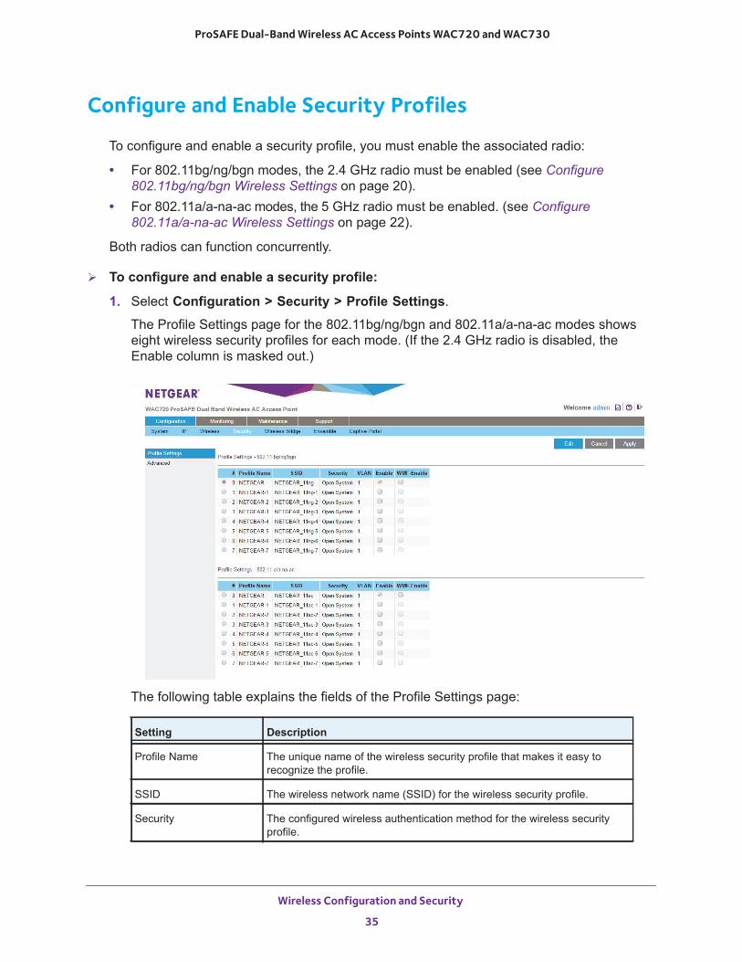
Configure and Enable Security Profiles
To configure and enable a security profile, you must enable the associated radio:
• For 802.11bg/ng/bgn modes, the 2.4 GHz radio must be enabled (see Configure 802.11bg/ng/bgn Wireless Settings on page 20).
• For 802.11a/a-na-ac modes, the 5 GHz radio must be enabled. (see Configure 802.11a/a-na-ac Wireless Settings on page 22).
Both radios can function concurrently.
To configure and enable a security profile:
1. Select Configuration > Security > Profile Settings.
The Profile Settings page for the 802.11bg/ng/bgn and 802.11a/a-na-ac modes shows eight wireless security profiles for each mode. (If the 2.4 GHz radio is disabled, the Enable column is masked out.)
The following table explains the fields of the Profile Settings page:
Setting Description
Profile Name The unique name of the wireless security profile that makes it easy to recognize the profile.
SSID The wireless network name (SSID) for the wireless security profile.
Security The configured wireless authentication method for the wireless security profile.
Wireless Configuration and Security
35
ProSAFE Dual-Band Wireless AC Access Points WAC720 and WAC730
2. To configure a wireless security profile, select the corresponding radio button to the left of the wireless security profile.
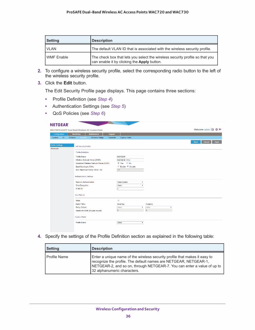
3. Click the Edit button.
The Edit Security Profile page displays. This page contains three sections:
• Profile Definition (see Step 4)• Authentication Settings (see Step 5)• QoS Policies (see Step 6)
4. Specify the settings of the Profile Definition section as explained in the following table:
VLAN The default VLAN ID that is associated with the wireless security profile.
WMF Enable The check box that lets you select the wireless security profile so that you can enable it by clicking the Apply button.
Setting Description
Profile Name Enter a unique name of the wireless security profile that makes it easy to recognize the profile. The default names are NETGEAR, NETGEAR-1, NETGEAR-2, and so on, through NETGEAR-7. You can enter a value of up to 32 alphanumeric characters.
Setting Description
Wireless Configuration and Security
36
ProSAFE Dual-Band Wireless AC Access Points WAC720 and WAC730
5. Specify the settings of the Authentication Settings section as explained in the following table.
The wireless access point is set by default as an open system with no authentication. When you configure network authentication, bear in mind the following:
• If you are using access point mode (which is the default mode if you did not enable wireless bridging), then all options are available. In other modes such as bridge mode, some options might be unavailable.
• Not all wireless adapters support WPA or WPA2. Windows XP, Windows 2000 with Service Pack 3, and Windows Vista do include the client software that supports WPA. However, client software is required on the client. Consult the product documentation for your wireless adapter and WPA or WPA2 client software for instructions about how to configure WPA2 settings.
Wireless Network Name (SSID)
The wireless network name (SSID) for the wireless security profile. The default names depend on the selected radio band:• 802.11bg/ng/bgn. The default names are NETGEAR_11ng,
NETGEAR_11ng-1, NETGEAR_11ng-2, and so on, through NETGEAR_11ng-7 for the eighth profile.
• 802.11a/na. The default names are NETGEAR_11ac, NETGEAR_11ac-1, NETGEAR_11ac-2, and so on, through NETGEAR_11ac-7 for the eighth profile.
Broadcast Wireless Network Name (SSID)
Select the Yes radio button to enable the wireless access point to broadcast its SSID, allowing wireless stations with a null (blank) SSID to adopt the wireless access point’s SSID. Yes is the default setting. To prevent the SSID from being broadcast, select the No radio button.
Setting Description
Network Authentication and Data Encryption
Note: The data encryption fields that display on the page depend on your selection from the Network Authentication menu.
Open System This is the default setting. Use an open system without any encryption. See Configure Legacy 802.1X on page 39.
Legacy 802.1X Configure the RADIUS server settings. Encryption is not supported.See Configure Legacy 802.1X on page 39.
WPA with RADIUS Configure the RADIUS server settings and select TKIP or TKIP + AES encryption.See Configure WPA With RADIUS and WPA & WPA2 With RADIUS on page 39.
Setting Description
Wireless Configuration and Security
37
ProSAFE Dual-Band Wireless AC Access Points WAC720 and WAC730
6. (Optional) In the QoS Policies section, select a QoS policy from the Incoming menu, Outgoing menu, or both. Depending on your selection, the policy is applied to incoming packets, outgoing packets, or both incoming and outgoing packets, and is displayed in the Policy Details fields.
Note: To be able to select a QoS policy, you must first configure one or more policies (see Configure and Manage Quality of Service Policies on page 83).
7. Click the Apply button.
Your settings are saved.
Network Authentication and Data Encryption(continued)
WPA2 with RADIUS
Configure the RADIUS server settings and select AES or TKIP + AES encryption. See Configure WPA With RADIUS and WPA & WPA2 With RADIUS on page 39.
Note: Select this setting only if all clients support WPA2.
WPA & WPA2 with RADIUS
Configure the RADIUS server setting. TKIP + AES encryption is the default encryption.See Configure WPA With RADIUS and WPA & WPA2 With RADIUS on page 39.
Note: This setting allows clients to connect through either WPA with TKIP or WPA2 with AES.
WPA-PSK Enter a WPA passphrase and select TKIP or TKIP + AES encryption. See Configure WPA-PSK, WPA2-PSK, and WPA-PSK & WPA2-PSK on page 40.
WPA2-PSK Enter a WPA passphrase and select AES or TKIP + AES encryption. See Configure WPA-PSK, WPA2-PSK, and WPA-PSK & WPA2-PSK on page 40.
Note: Select this setting only if all clients support WPA2.
WPA-PSK & WPA2-PSK
Enter a WPA passphrase. TKIP + AES encryption is the default encryption. See Configure WPA-PSK, WPA2-PSK, and WPA-PSK & WPA2-PSK on page 40.
Note: This setting allows clients to connect through either WPA with TKIP or WPA2 with AES.
Wireless Client Security Separation
If you enable wireless client security separation by selecting Enable from the menu, the associated wireless clients cannot communicate with each other. By default, Disable is selected from the menu. This feature is intended for hotspots and other public access situations.
VLAN ID Enter the VLAN ID to be associated with this wireless security profile. The default VLAN ID is 1. The VLAN ID must match the VLAN ID that is used by the other devices in your network.
Setting Description
Wireless Configuration and Security
38
ProSAFE Dual-Band Wireless AC Access Points WAC720 and WAC730
WARNING:
If you use a wireless computer to configure wireless security settings, you are disconnected when you click the Apply button. Reconfigure your wireless computer to match the new settings, or access the wireless access point from a wired computer to make further changes.
Change the QoS Policy for a Wireless Security Profile
To change the QoS policy for a wireless security profile:
1. Select Configuration > Security > Profile Settings.
The Profile Settings page displays.
2. Select the radio button the left of the wireless security profile.3. Click the Edit button.
The Edit Security Profile page displays.
4. From the menu from which you can select another QoS policy, select None.5. Click the Apply button.
The old policy is removed from the security profile.
6. Select the new QoS policy from the same menu.7. Click the Apply button.
Your settings are saved.
Configure Legacy 802.1XTo use legacy 802.1X security, you must define RADIUS server settings. For information about RADIUS servers, see Configure RADIUS Server Settings on page 41.
When you select Legacy 802.1X from the Network Authentication menu, the Data Encryption menu is automatically set to None. To use legacy 802.1X security, you must define the RADIUS servers only.
Configure WPA With RADIUS and WPA & WPA2 With RADIUSWPA and WPA & WPA2 security require RADIUS-based 802.1x authentication, so you also must define RADIUS server settings. For information about RADIUS servers, see Configure RADIUS Server Settings on page 41.
The selections that are available from the Data Encryption menu depend on the type of WPA authentication that you select from the Network Authentication menu and are shown in the following table.
Wireless Configuration and Security
39
ProSAFE Dual-Band Wireless AC Access Points WAC720 and WAC730
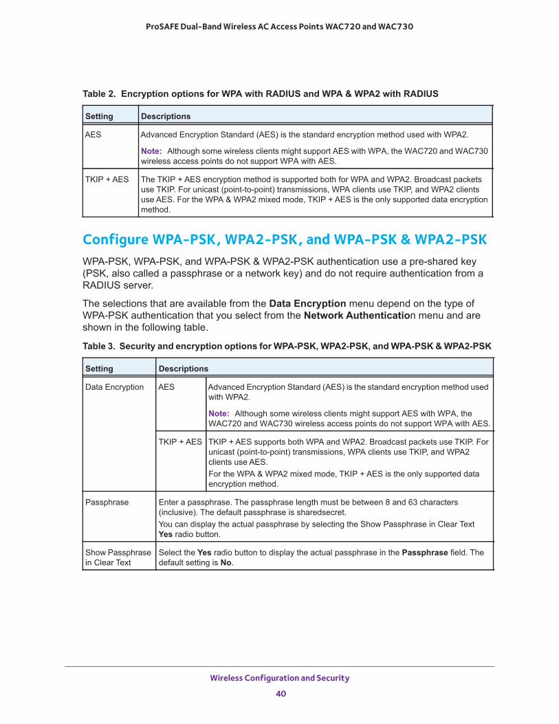
Configure WPA-PSK, WPA2-PSK, and WPA-PSK & WPA2-PSKWPA-PSK, WPA-PSK, and WPA-PSK & WPA2-PSK authentication use a pre-shared key (PSK, also called a passphrase or a network key) and do not require authentication from a RADIUS server.
The selections that are available from the Data Encryption menu depend on the type of WPA-PSK authentication that you select from the Network Authentication menu and are shown in the following table.
Table 2. Encryption options for WPA with RADIUS and WPA & WPA2 with RADIUS
Setting Descriptions
AES Advanced Encryption Standard (AES) is the standard encryption method used with WPA2.
Note: Although some wireless clients might support AES with WPA, the WAC720 and WAC730 wireless access points do not support WPA with AES.
TKIP + AES The TKIP + AES encryption method is supported both for WPA and WPA2. Broadcast packets use TKIP. For unicast (point-to-point) transmissions, WPA clients use TKIP, and WPA2 clients use AES. For the WPA & WPA2 mixed mode, TKIP + AES is the only supported data encryption method.
Table 3. Security and encryption options for WPA-PSK, WPA2-PSK, and WPA-PSK & WPA2-PSK
Setting Descriptions
Data Encryption AES Advanced Encryption Standard (AES) is the standard encryption method used with WPA2.
Note: Although some wireless clients might support AES with WPA, the WAC720 and WAC730 wireless access points do not support WPA with AES.
TKIP + AES TKIP + AES supports both WPA and WPA2. Broadcast packets use TKIP. For unicast (point-to-point) transmissions, WPA clients use TKIP, and WPA2 clients use AES.For the WPA & WPA2 mixed mode, TKIP + AES is the only supported data encryption method.
Passphrase Enter a passphrase. The passphrase length must be between 8 and 63 characters (inclusive). The default passphrase is sharedsecret.You can display the actual passphrase by selecting the Show Passphrase in Clear Text Yes radio button.
Show Passphrase in Clear Text
Select the Yes radio button to display the actual passphrase in the Passphrase field. The default setting is No.
Wireless Configuration and Security
40
ProSAFE Dual-Band Wireless AC Access Points WAC720 and WAC730
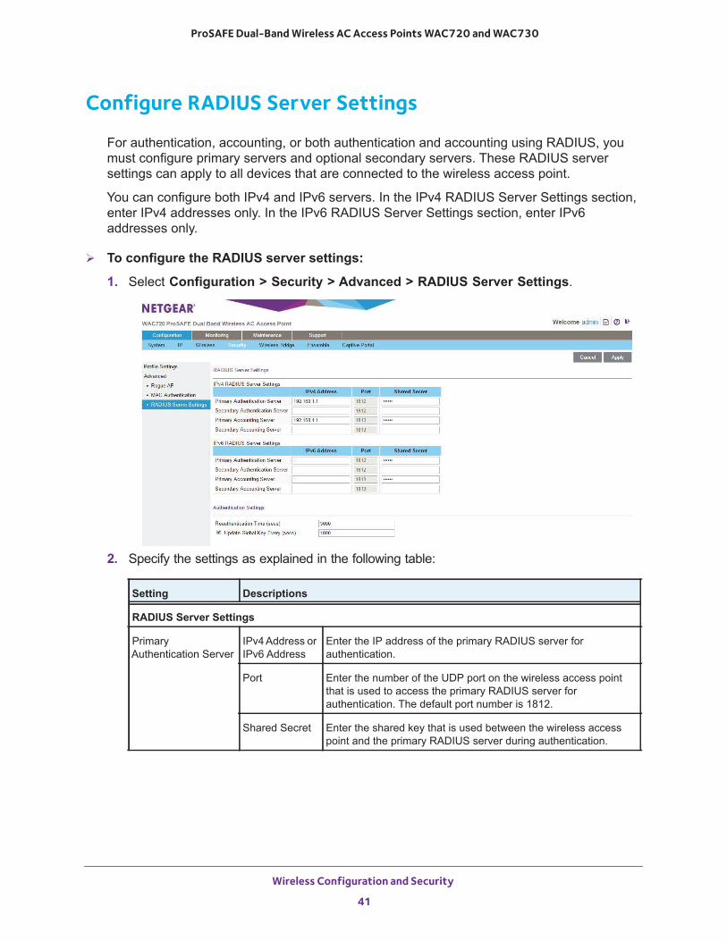
Configure RADIUS Server Settings
For authentication, accounting, or both authentication and accounting using RADIUS, you must configure primary servers and optional secondary servers. These RADIUS server settings can apply to all devices that are connected to the wireless access point.
You can configure both IPv4 and IPv6 servers. In the IPv4 RADIUS Server Settings section, enter IPv4 addresses only. In the IPv6 RADIUS Server Settings section, enter IPv6 addresses only.
To configure the RADIUS server settings:
1. Select Configuration > Security > Advanced > RADIUS Server Settings.
2. Specify the settings as explained in the following table:
Setting Descriptions
RADIUS Server Settings
PrimaryAuthentication Server
IPv4 Address or IPv6 Address
Enter the IP address of the primary RADIUS server for authentication.
Port Enter the number of the UDP port on the wireless access point that is used to access the primary RADIUS server for authentication. The default port number is 1812.
Shared Secret Enter the shared key that is used between the wireless access point and the primary RADIUS server during authentication.
Wireless Configuration and Security
41
ProSAFE Dual-Band Wireless AC Access Points WAC720 and WAC730
3. Click the Apply button.
Your settings are saved.
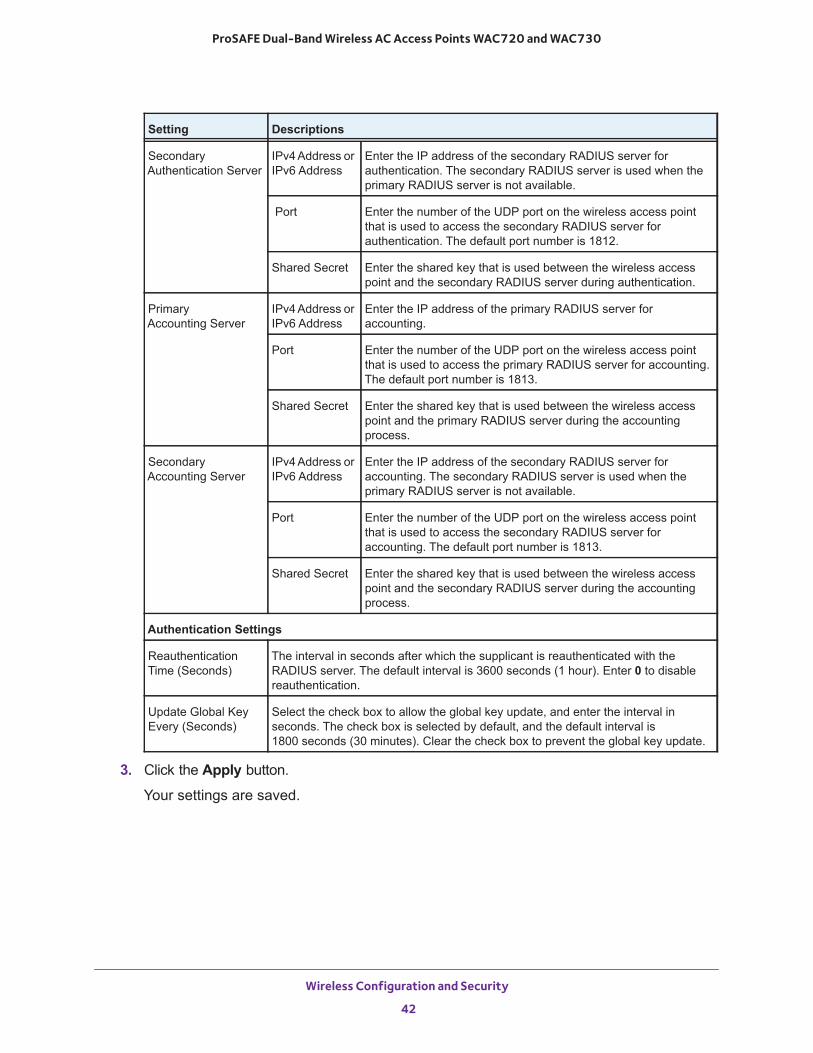
SecondaryAuthentication Server
IPv4 Address or IPv6 Address
Enter the IP address of the secondary RADIUS server for authentication. The secondary RADIUS server is used when the primary RADIUS server is not available.
Port Enter the number of the UDP port on the wireless access point that is used to access the secondary RADIUS server for authentication. The default port number is 1812.
Shared Secret Enter the shared key that is used between the wireless access point and the secondary RADIUS server during authentication.
PrimaryAccounting Server
IPv4 Address or IPv6 Address
Enter the IP address of the primary RADIUS server for accounting.
Port Enter the number of the UDP port on the wireless access point that is used to access the primary RADIUS server for accounting. The default port number is 1813.
Shared Secret Enter the shared key that is used between the wireless access point and the primary RADIUS server during the accounting process.
SecondaryAccounting Server
IPv4 Address or IPv6 Address
Enter the IP address of the secondary RADIUS server for accounting. The secondary RADIUS server is used when the primary RADIUS server is not available.
Port Enter the number of the UDP port on the wireless access point that is used to access the secondary RADIUS server for accounting. The default port number is 1813.
Shared Secret Enter the shared key that is used between the wireless access point and the secondary RADIUS server during the accounting process.
Authentication Settings
Reauthentication Time (Seconds)
The interval in seconds after which the supplicant is reauthenticated with the RADIUS server. The default interval is 3600 seconds (1 hour). Enter 0 to disable reauthentication.
Update Global Key Every (Seconds)
Select the check box to allow the global key update, and enter the interval in seconds. The check box is selected by default, and the default interval is 1800 seconds (30 minutes). Clear the check box to prevent the global key update.
Setting Descriptions
Wireless Configuration and Security
42
ProSAFE Dual-Band Wireless AC Access Points WAC720 and WAC730
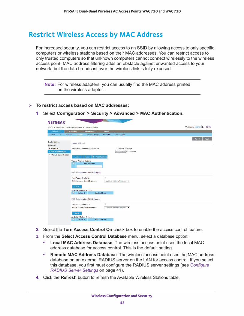
Restrict Wireless Access by MAC Address
For increased security, you can restrict access to an SSID by allowing access to only specific computers or wireless stations based on their MAC addresses. You can restrict access to only trusted computers so that unknown computers cannot connect wirelessly to the wireless access point. MAC address filtering adds an obstacle against unwanted access to your network, but the data broadcast over the wireless link is fully exposed.
Note: For wireless adapters, you can usually find the MAC address printed on the wireless adapter.
To restrict access based on MAC addresses:
1. Select Configuration > Security > Advanced > MAC Authentication.
2. Select the Turn Access Control On check box to enable the access control feature.3. From the Select Access Control Database menu, select a database option:
• Local MAC Address Database. The wireless access point uses the local MAC address database for access control. This is the default setting.
• Remote MAC Address Database. The wireless access point uses the MAC address database on an external RADIUS server on the LAN for access control. If you select this database, you first must configure the RADIUS server settings (see Configure RADIUS Server Settings on page 41).
4. Click the Refresh button to refresh the Available Wireless Stations table.
Wireless Configuration and Security
43
ProSAFE Dual-Band Wireless AC Access Points WAC720 and WAC730
The wireless access point places the MAC addresses of the attached wireless stations in this table.
5. Populate the Trusted Wireless Stations table by one of the following methods:• Select MAC addresses from the Available Wireless Stations table:
a. Select individual check boxes for MAC addresses, or select all MAC addresses by selecting the check box in the heading.
b. Click the Move button to transfer the MAC addresses from the Available Wireless Stations table to the Trusted Wireless Stations table.
• Enter MAC addresses manually:a. Enter a MAC address directly in the Trusted Wireless Stations table.b. Click the Add button.
To delete a MAC address from the Trusted Wireless Stations table, select individual check boxes for MAC addresses, or select all MAC addresses by selecting the check box in the heading, and then click the Delete button.
6. Click the Apply button.
Your settings are saved.
Now, only devices in the Trusted Wireless Stations table are allowed to connect to the wireless access point over a wireless connection.
WARNING:
When configuring the wireless access point from a wireless computer whose MAC address is not on the access control list, you lose your wireless connection when you click the Apply button. You then must access the wireless access point from a wired computer or from a wireless computer that is on the access control list to make any further changes.
Enable Rogue AP Detection
Unidentified access points that use the SSID of a legitimate network can present a serious security threat. Detecting rogue access points involves scanning the wireless environment on all available channels, looking for unidentified access points.
When rogue AP detection is enabled, the access point will interact only with devices in the Known AP list.
Wireless Configuration and Security
44
ProSAFE Dual-Band Wireless AC Access Points WAC720 and WAC730
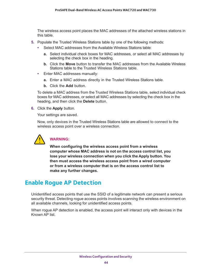
To enable rogue AP detection:
1. Select Configuration > Security > Advanced > Rogue AP.
2. Select the Turn Rogue AP Detection On check box.3. Select a detection policy from the Rogue AP Detection Policy menu:
• Mild. The AP scans for unknown APs every 180 seconds.• Moderate. The AP scans for unknown APs every 60 seconds.• Aggressive. The AP scans for unknown APs every 10 seconds.
4. To import a list of known APs, click the Choose File button.
The file you import must be a plain-text file with a .txt or .cfg extension. Entries in the file are MAC addresses in hexadecimal format with each octet separated by colons, for example 00:11:22:33:44:55. Separate entries with a single space. For the AP to accept the file, it must contain only MAC addresses.
5. Click the Apply button.
Your settings are saved.
Wireless Configuration and Security
45
ProSAFE Dual-Band Wireless AC Access Points WAC720 and WAC730
Schedule the Wireless Radios to Be Turned Off
Scheduling the wireless radios to be turned off is a green feature that allows you to turn off the wireless radios during scheduled vacations, office shutdowns, on evenings, or on weekends.
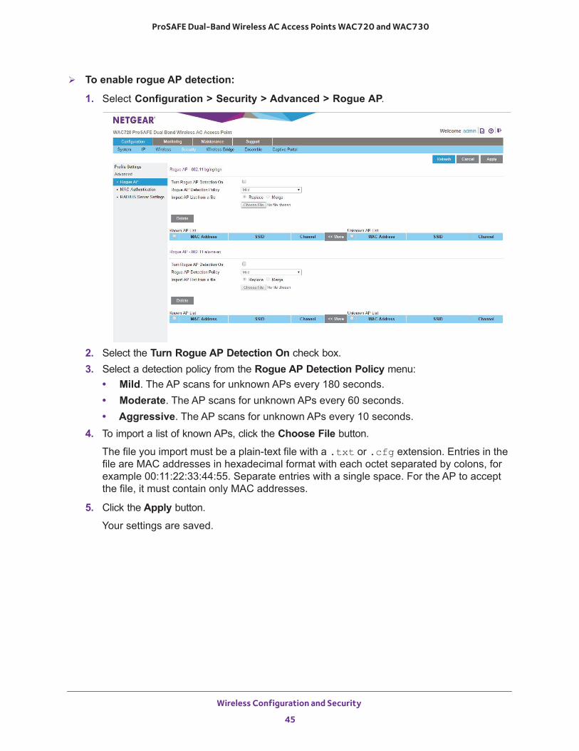
To schedule the radios to be turned on and off:
1. Select Configuration > Wireless > Basic > Wireless Scheduling.
2. Specify the settings as explained in the following table:
3. Click the Apply button.
Your settings are saved.
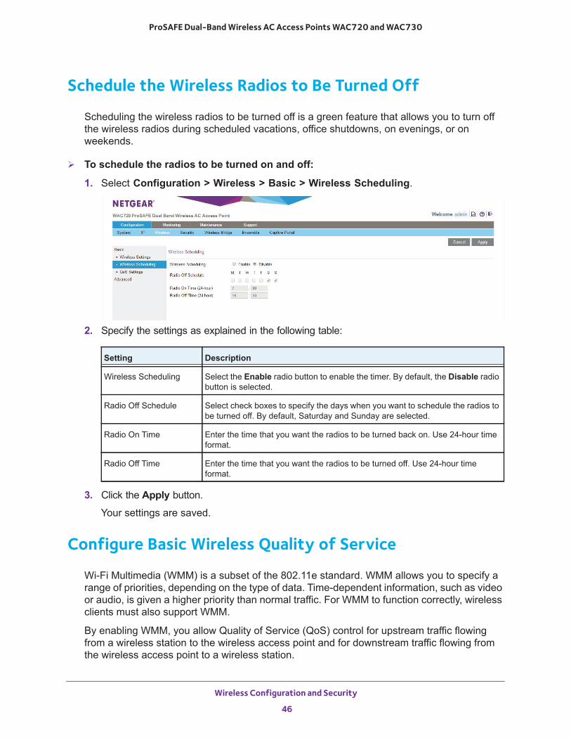
Configure Basic Wireless Quality of Service
Wi-Fi Multimedia (WMM) is a subset of the 802.11e standard. WMM allows you to specify a range of priorities, depending on the type of data. Time-dependent information, such as video or audio, is given a higher priority than normal traffic. For WMM to function correctly, wireless clients must also support WMM.
By enabling WMM, you allow Quality of Service (QoS) control for upstream traffic flowing from a wireless station to the wireless access point and for downstream traffic flowing from the wireless access point to a wireless station.
Setting Description
Wireless Scheduling Select the Enable radio button to enable the timer. By default, the Disable radio button is selected.
Radio Off Schedule Select check boxes to specify the days when you want to schedule the radios to be turned off. By default, Saturday and Sunday are selected.
Radio On Time Enter the time that you want the radios to be turned back on. Use 24-hour time format.
Radio Off Time Enter the time that you want the radios to be turned off. Use 24-hour time format.
Wireless Configuration and Security
46
ProSAFE Dual-Band Wireless AC Access Points WAC720 and WAC730
WMM defines the following four queues in decreasing order of priority:
• Voice. The highest priority queue with minimum delay, which makes it ideal for applications like VoIP and streaming media.
• Video. The second highest priority queue with low delay is given to this queue. Video applications are routed to this queue.
• Best Effort. The medium priority queue with medium delay is given to this queue. Most standard IP applications use this queue.
• Background. Low priority queue with high throughput. Applications, such as FTP, that are not time-sensitive but require high throughput can use this queue.
The WMM Powersave feature saves power for battery-powered equipment by increasing the efficiency and flexibility of data transmission.
Note: For information about how to configure advanced wireless QoS, that is, to configure specific Enhanced Distributed Channel Access (EDCA) settings, see Configure Advanced Quality of Service Settings on page 81.
To configure basic wireless QoS:
1. Select Configuration > Wireless > Basic > QoS Settings.
2. Enable or disable the WMM features:• Enable Wi-Fi Multimedia (WMM). To enable this feature, select the Enable radio
button, which is the default setting. Select the Disable radio button to disable the feature.
• WMM Powersave. To enable this feature, select the Enable radio button, which is the default setting. Select the Disable radio button to disable the feature.
3. Click the Apply button.
Your settings are saved.
Wireless Configuration and Security
47

4
4. Management and MonitoringThis chapter describes how to use the management and monitoring features of the wireless access point. The chapter includes the following sections:
• Enable Remote Management• Upgrade the Wireless Access Point Software• Manage the Configuration File or Reset to Factory Defaults• Change the Administrator Password• Manage User Accounts• Enable the Syslog Server• Monitor the Wireless Access Point• View the Activity Log• View the Traffic Statistics• Enable and Configure Ensemble Mode
48
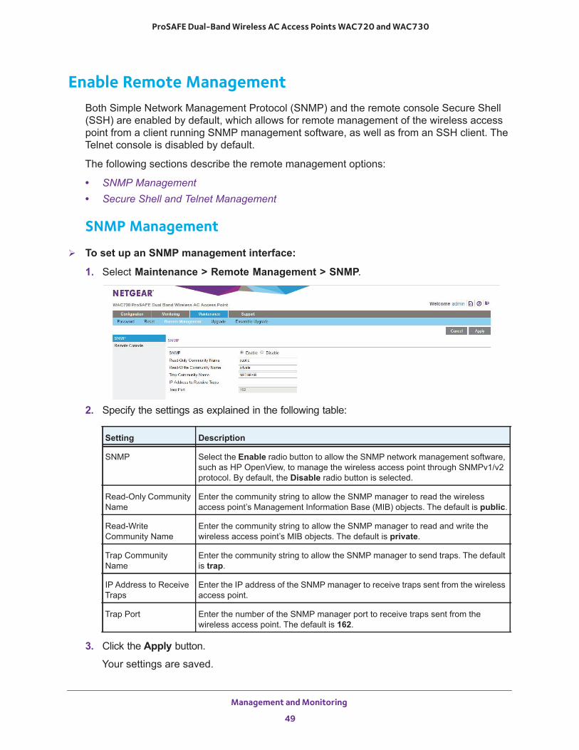
ProSAFE Dual-Band Wireless AC Access Points WAC720 and WAC730
Enable Remote ManagementBoth Simple Network Management Protocol (SNMP) and the remote console Secure Shell (SSH) are enabled by default, which allows for remote management of the wireless access point from a client running SNMP management software, as well as from an SSH client. The Telnet console is disabled by default.
The following sections describe the remote management options:
• SNMP Management• Secure Shell and Telnet Management
SNMP Management
To set up an SNMP management interface:
1. Select Maintenance > Remote Management > SNMP.
2. Specify the settings as explained in the following table:
3. Click the Apply button.
Your settings are saved.
Setting Description
SNMP Select the Enable radio button to allow the SNMP network management software, such as HP OpenView, to manage the wireless access point through SNMPv1/v2 protocol. By default, the Disable radio button is selected.
Read-Only Community Name
Enter the community string to allow the SNMP manager to read the wireless access point’s Management Information Base (MIB) objects. The default is public.
Read-Write Community Name
Enter the community string to allow the SNMP manager to read and write the wireless access point’s MIB objects. The default is private.
Trap Community Name
Enter the community string to allow the SNMP manager to send traps. The default is trap.
IP Address to Receive Traps
Enter the IP address of the SNMP manager to receive traps sent from the wireless access point.
Trap Port Enter the number of the SNMP manager port to receive traps sent from the wireless access point. The default is 162.
Management and Monitoring
49
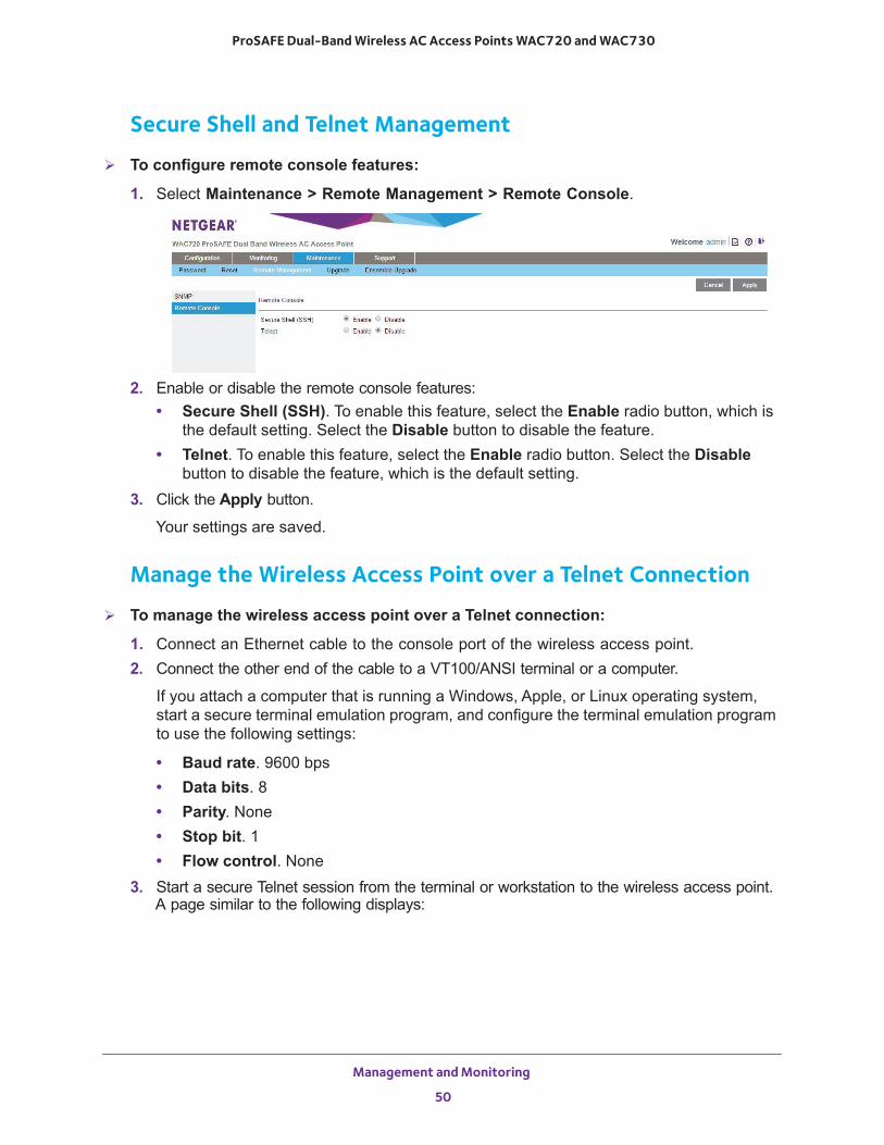
ProSAFE Dual-Band Wireless AC Access Points WAC720 and WAC730
Secure Shell and Telnet Management
To configure remote console features:
1. Select Maintenance > Remote Management > Remote Console.
2. Enable or disable the remote console features:• Secure Shell (SSH). To enable this feature, select the Enable radio button, which is
the default setting. Select the Disable button to disable the feature.• Telnet. To enable this feature, select the Enable radio button. Select the Disable
button to disable the feature, which is the default setting.3. Click the Apply button.
Your settings are saved.
Manage the Wireless Access Point over a Telnet Connection
To manage the wireless access point over a Telnet connection:
1. Connect an Ethernet cable to the console port of the wireless access point.2. Connect the other end of the cable to a VT100/ANSI terminal or a computer.
If you attach a computer that is running a Windows, Apple, or Linux operating system, start a secure terminal emulation program, and configure the terminal emulation program to use the following settings:
• Baud rate. 9600 bps• Data bits. 8• Parity. None• Stop bit. 1• Flow control. None
3. Start a secure Telnet session from the terminal or workstation to the wireless access point. A page similar to the following displays:
Management and Monitoring
50
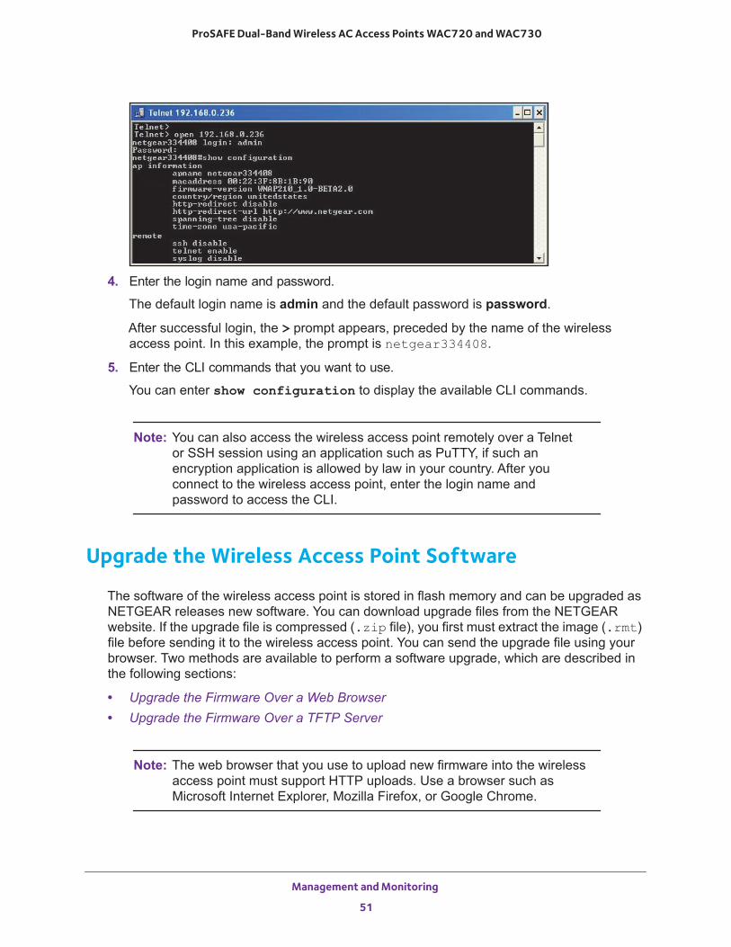
ProSAFE Dual-Band Wireless AC Access Points WAC720 and WAC730
4. Enter the login name and password.
The default login name is admin and the default password is password.
After successful login, the > prompt appears, preceded by the name of the wireless access point. In this example, the prompt is netgear334408.
5. Enter the CLI commands that you want to use.
You can enter show configuration to display the available CLI commands.
Note: You can also access the wireless access point remotely over a Telnet or SSH session using an application such as PuTTY, if such an encryption application is allowed by law in your country. After you connect to the wireless access point, enter the login name and password to access the CLI.
Upgrade the Wireless Access Point Software
The software of the wireless access point is stored in flash memory and can be upgraded as NETGEAR releases new software. You can download upgrade files from the NETGEAR website. If the upgrade file is compressed (.zip file), you first must extract the image (.rmt) file before sending it to the wireless access point. You can send the upgrade file using your browser. Two methods are available to perform a software upgrade, which are described in the following sections:
• Upgrade the Firmware Over a Web Browser • Upgrade the Firmware Over a TFTP Server
Note: The web browser that you use to upload new firmware into the wireless access point must support HTTP uploads. Use a browser such as Microsoft Internet Explorer, Mozilla Firefox, or Google Chrome.
Management and Monitoring
51
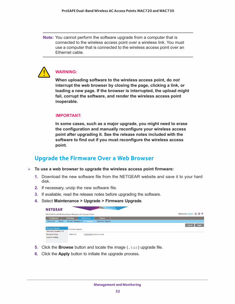
ProSAFE Dual-Band Wireless AC Access Points WAC720 and WAC730
Note: You cannot perform the software upgrade from a computer that is connected to the wireless access point over a wireless link. You must use a computer that is connected to the wireless access point over an Ethernet cable.
WARNING:
When uploading software to the wireless access point, do not interrupt the web browser by closing the page, clicking a link, or loading a new page. If the browser is interrupted, the upload might fail, corrupt the software, and render the wireless access point inoperable.
IMPORTANT:
In some cases, such as a major upgrade, you might need to erase the configuration and manually reconfigure your wireless access point after upgrading it. See the release notes included with the software to find out if you must reconfigure the wireless access point.
Upgrade the Firmware Over a Web Browser
To use a web browser to upgrade the wireless access point firmware:
1. Download the new software file from the NETGEAR website and save it to your hard disk.
2. If necessary, unzip the new software file.3. If available, read the release notes before upgrading the software.4. Select Maintenance > Upgrade > Firmware Upgrade.
5. Click the Browse button and locate the image (.tar) upgrade file.6. Click the Apply button to initiate the upgrade process.
Management and Monitoring
52

ProSAFE Dual-Band Wireless AC Access Points WAC720 and WAC730
During the upgrade process, the wireless access point automatically restarts. The upgrade process typically takes several minutes. When the Test LED turns off, wait a few more seconds before doing anything with the wireless access point.
7. Verify that the new software file was installed by selecting Monitoring > System.
The System page displays. The firmware version is shown in the Access Point Information section of the page.
Upgrade the Firmware Over a TFTP ServerTo use this method, you need access to a TFTP server.
To use a TFTP server to upgrade the wireless access point firmware:
1. Download the new software file from the NETGEAR website and save it to your hard disk.
2. Place the software file in your TFTP server location.3. If available, read the release notes before upgrading the software.4. Select Maintenance > Upgrade > Firmware Upgrade TFTP.
5. Specify the following information:• Firmware File Name. The name of the software file.• TFTP Server IP. The IP address of your TFTP server.
6. Click the Apply button to initiate the upgrade process.
During the upgrade process, the wireless access point automatically restarts. The upgrade process typically takes several minutes. When the Test LED turns off, wait a few more seconds before doing anything with the wireless access point.
7. Verify that the new software file was installed by selecting Monitoring > System.
The System page displays. The firmware version is shown in the Access Point Information section of the page.
Management and Monitoring
53
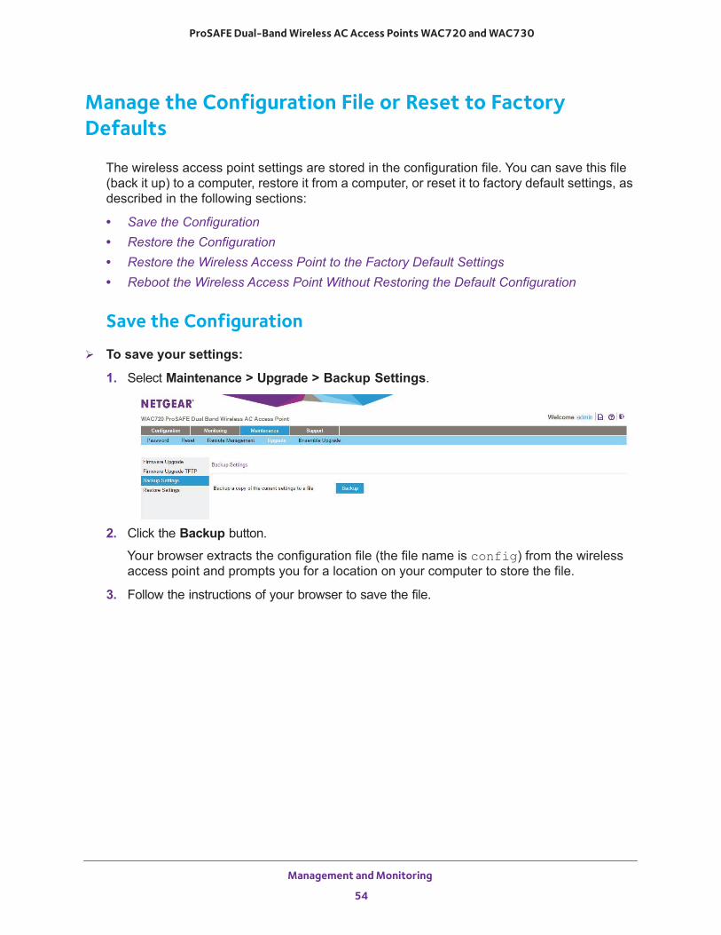
ProSAFE Dual-Band Wireless AC Access Points WAC720 and WAC730
Manage the Configuration File or Reset to Factory Defaults
The wireless access point settings are stored in the configuration file. You can save this file (back it up) to a computer, restore it from a computer, or reset it to factory default settings, as described in the following sections:
• Save the Configuration• Restore the Configuration• Restore the Wireless Access Point to the Factory Default Settings• Reboot the Wireless Access Point Without Restoring the Default Configuration
Save the Configuration
To save your settings:
1. Select Maintenance > Upgrade > Backup Settings.
2. Click the Backup button.
Your browser extracts the configuration file (the file name is config) from the wireless access point and prompts you for a location on your computer to store the file.
3. Follow the instructions of your browser to save the file.
Management and Monitoring
54
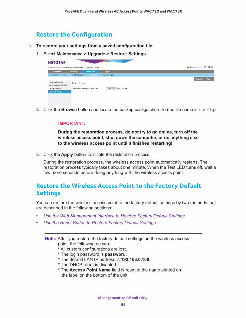
ProSAFE Dual-Band Wireless AC Access Points WAC720 and WAC730
Restore the Configuration
To restore your settings from a saved configuration file:
1. Select Maintenance > Upgrade > Restore Settings.
2. Click the Browse button and locate the backup configuration file (the file name is config).
IMPORTANT:
During the restoration process, do not try to go online, turn off the wireless access point, shut down the computer, or do anything else to the wireless access point until it finishes restarting!
3. Click the Apply button to initiate the restoration process.
During the restoration process, the wireless access point automatically restarts. The restoration process typically takes about one minute. When the Test LED turns off, wait a few more seconds before doing anything with the wireless access point.
Restore the Wireless Access Point to the Factory Default SettingsYou can restore the wireless access point to the factory default settings by two methods that are described in the following sections:
• Use the Web Management Interface to Restore Factory Default Settings • Use the Reset Button to Restore Factory Default Settings
Note: After you restore the factory default settings on the wireless access point, the following occurs:* All custom configurations are lost.* The login password is password.* The default LAN IP address is 192.168.0.100.* The DHCP client is disabled.* The Access Point Name field is reset to the name printed on the label on the bottom of the unit.
Management and Monitoring
55
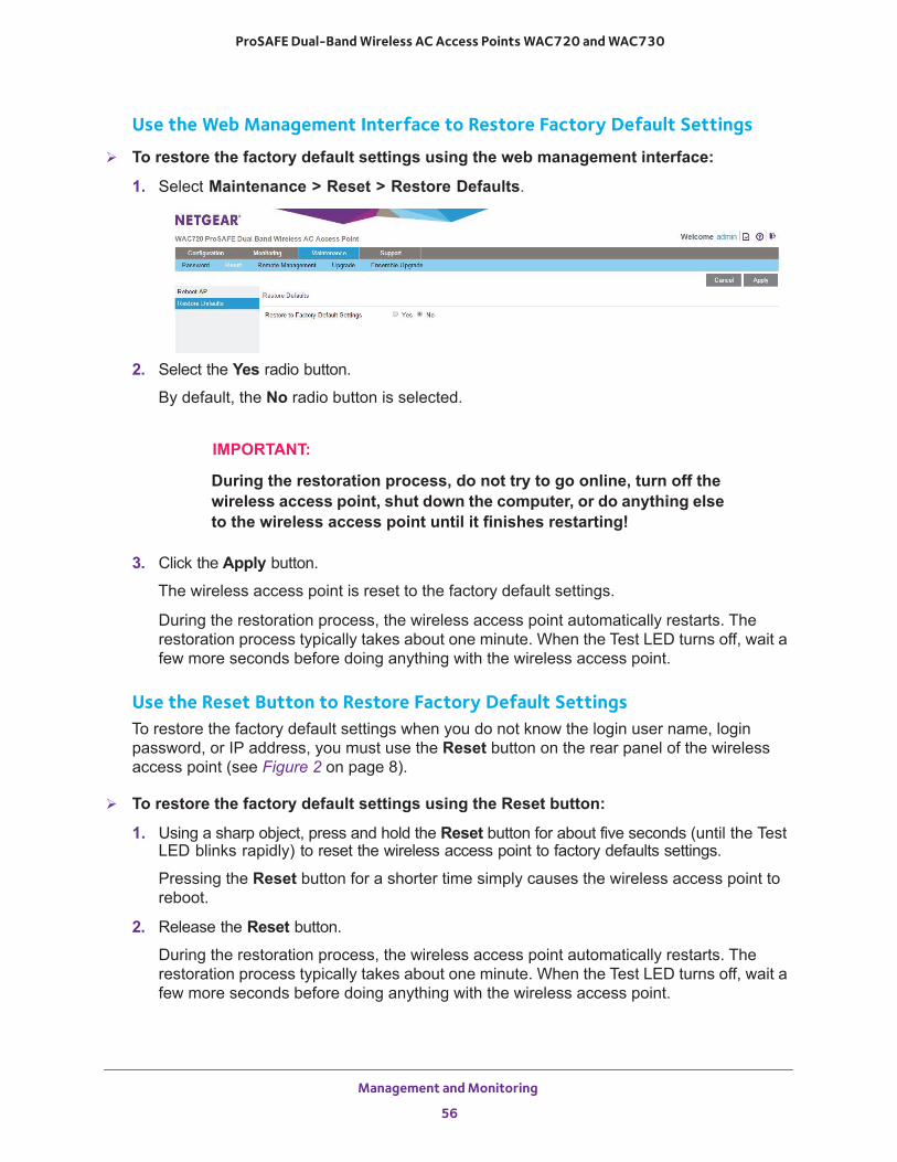
ProSAFE Dual-Band Wireless AC Access Points WAC720 and WAC730
Use the Web Management Interface to Restore Factory Default Settings
To restore the factory default settings using the web management interface:
1. Select Maintenance > Reset > Restore Defaults.
2. Select the Yes radio button.
By default, the No radio button is selected.
IMPORTANT:
During the restoration process, do not try to go online, turn off the wireless access point, shut down the computer, or do anything else to the wireless access point until it finishes restarting!
3. Click the Apply button.
The wireless access point is reset to the factory default settings.
During the restoration process, the wireless access point automatically restarts. The restoration process typically takes about one minute. When the Test LED turns off, wait a few more seconds before doing anything with the wireless access point.
Use the Reset Button to Restore Factory Default SettingsTo restore the factory default settings when you do not know the login user name, login password, or IP address, you must use the Reset button on the rear panel of the wireless access point (see Figure 2 on page 8).
To restore the factory default settings using the Reset button:
1. Using a sharp object, press and hold the Reset button for about five seconds (until the Test LED blinks rapidly) to reset the wireless access point to factory defaults settings.
Pressing the Reset button for a shorter time simply causes the wireless access point to reboot.
2. Release the Reset button.
During the restoration process, the wireless access point automatically restarts. The restoration process typically takes about one minute. When the Test LED turns off, wait a few more seconds before doing anything with the wireless access point.
Management and Monitoring
56
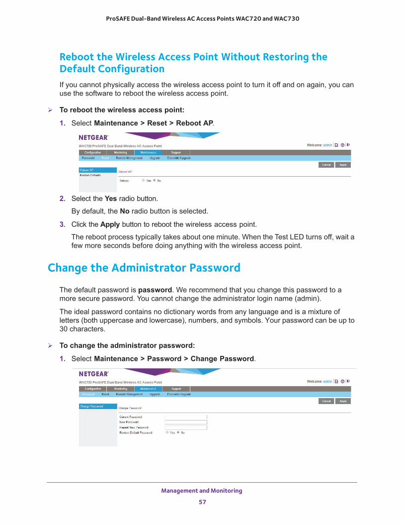
ProSAFE Dual-Band Wireless AC Access Points WAC720 and WAC730
Reboot the Wireless Access Point Without Restoring theDefault ConfigurationIf you cannot physically access the wireless access point to turn it off and on again, you can use the software to reboot the wireless access point.
To reboot the wireless access point:
1. Select Maintenance > Reset > Reboot AP.
2. Select the Yes radio button.
By default, the No radio button is selected.
3. Click the Apply button to reboot the wireless access point.
The reboot process typically takes about one minute. When the Test LED turns off, wait a few more seconds before doing anything with the wireless access point.
Change the Administrator Password
The default password is password. We recommend that you change this password to a more secure password. You cannot change the administrator login name (admin).
The ideal password contains no dictionary words from any language and is a mixture of letters (both uppercase and lowercase), numbers, and symbols. Your password can be up to 30 characters.
To change the administrator password:
1. Select Maintenance > Password > Change Password.
Management and Monitoring
57
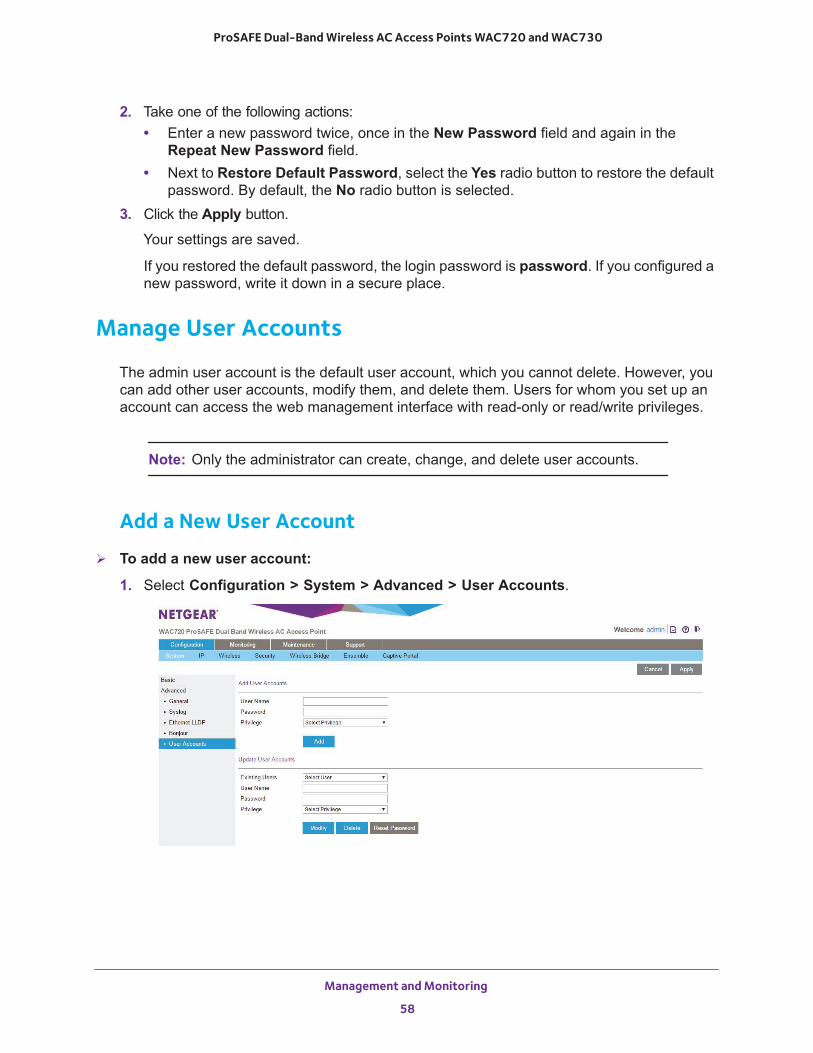
ProSAFE Dual-Band Wireless AC Access Points WAC720 and WAC730
2. Take one of the following actions:• Enter a new password twice, once in the New Password field and again in the
Repeat New Password field.• Next to Restore Default Password, select the Yes radio button to restore the default
password. By default, the No radio button is selected.3. Click the Apply button.
Your settings are saved.
If you restored the default password, the login password is password. If you configured a new password, write it down in a secure place.
Manage User Accounts
The admin user account is the default user account, which you cannot delete. However, you can add other user accounts, modify them, and delete them. Users for whom you set up an account can access the web management interface with read-only or read/write privileges.
Note: Only the administrator can create, change, and delete user accounts.
Add a New User Account
To add a new user account:
1. Select Configuration > System > Advanced > User Accounts.
Management and Monitoring
58
ProSAFE Dual-Band Wireless AC Access Points WAC720 and WAC730
2. Configure the settings in the upper part of the page as explained in the following table:
3. Click the Add button.
The user account is added.
4. Click the Apply button.
Your settings are saved.
Change the Name for a User Account
To change the name for a user account:
1. Select Configuration > System > Advanced > User Accounts.
The User Accounts page displays.
2. In the Update User Accounts section, select a user from the Existing Users menu.3. In the User Name field, modify the name.4. Click the Modify button.
The user name is changed.
5. Click the Apply button.
Your settings are saved.
Change the Privilege for a User Account
To change the privilege for a user account:
1. Select Configuration > System > Advanced > User Accounts.
The User Accounts page displays.
2. In the Update User Accounts section, select a user from the Existing Users menu.3. From the Privilege menu, select another privilege.4. Click the Reset Password button.
The password is reset to the default password, which is password.
5. Click the Apply button.
Your settings are saved.
Setting Description
User Name Enter a new user name.
Password Enter a password between 4 and 12 characters in length.
Privilege From the Privilege menu, select Read Write or Read Only.
Management and Monitoring
59
ProSAFE Dual-Band Wireless AC Access Points WAC720 and WAC730
Reset the Password for a User Account
To reset the password for a user account:
1. Select Configuration > System > Advanced > User Accounts.
The User Accounts page displays.
2. In the Update User Accounts section, select a user from the Existing Users menu.3. Click the Reset Password button.
The password is reset to the default password, which is password.
4. Click the Apply button.
Your settings are saved.
Note: If you want to modify a password, delete the user account, and then recreate the user account with the password of your choice.
Delete a User Account
To delete a user account:
1. Select Configuration > System > Advanced > User Accounts.
The User Accounts page displays.
2. In the Update User Accounts section, select a user from the Existing Users menu.3. Click the Delete button.4. Click the Apply button.
Your settings are saved.
Management and Monitoring
60
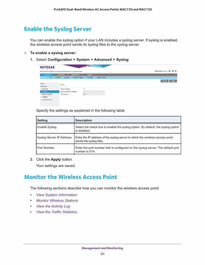
ProSAFE Dual-Band Wireless AC Access Points WAC720 and WAC730
Enable the Syslog Server
You can enable the syslog option if your LAN includes a syslog server. If syslog is enabled, the wireless access point sends its syslog files to the syslog server.
To enable a syslog server:
1. Select Configuration > System > Advanced > Syslog.
Specify the settings as explained in the following table:
2. Click the Apply button.
Your settings are saved.
Monitor the Wireless Access Point
The following sections describe how you can monitor the wireless access point:
• View System Information • Monitor Wireless Stations • View the Activity Log • View the Traffic Statistics
Setting Description
Enable Syslog Select the check box to enable the syslog option. By default, the syslog option is disabled.
Syslog Server IP Address Enter the IP address of the syslog server to which the wireless access point sends the syslog files.
Port Number Enter the port number that is configured on the syslog server. The default port number is 514.
Management and Monitoring
61
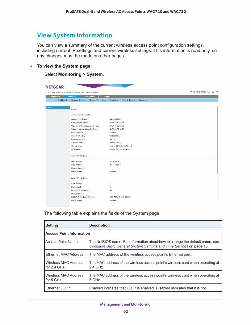
ProSAFE Dual-Band Wireless AC Access Points WAC720 and WAC730
View System InformationYou can view a summary of the current wireless access point configuration settings, including current IP settings and current wireless settings. This information is read only, so any changes must be made on other pages.
To view the System page:
Select Monitoring > System.
The following table explains the fields of the System page:
Setting Description
Access Point Information
Access Point Name The NetBIOS name. For information about how to change the default name, see Configure Basic General System Settings and Time Settings on page 16.
Ethernet MAC Address The MAC address of the wireless access point’s Ethernet port.
Wireless MAC Address for 2.4 GHz
The MAC address of the wireless access point’s wireless card when operating at 2.4 GHz.
Wireless MAC Address for 5 GHz
The MAC address of the wireless access point’s wireless card when operating at 5 GHz.
Ethernet LLDP Enabled indicates that LLDP is enabled. Disabled indicates that it is not.
Management and Monitoring
62
ProSAFE Dual-Band Wireless AC Access Points WAC720 and WAC730
Country/Region The country or region for which the wireless access point is licensed for use. For information about how to change the country or region, see Configure Basic General System Settings and Time Settings on page 16.
Note: It might not be legal to operate this wireless access point in a country or region other than one of those identified in this field.
Firmware Version The version of the firmware that is currently installed.
Serial Number The serial number of the wireless access point.
Current Time The current time. For information about how to change the time settings, see Configure Basic General System Settings and Time Settings on page 16.
AP Uptime The length of time since the access point became active.
Current IPv4 SettingsFor information about how to change any of these IP settings, see Configure the IPv4 Settings on page 18.
IP Address The IPv4 address of the wireless access point.
Subnet Mask The subnet mask for the address of the wireless access point.
Default Gateway The default IPv4 gateway for the wireless access point communication.
DHCP Client Enabled indicates that the current IP address was obtained from a DHCPv4 server on your LAN network. Disabled indicates a static IP configuration.
Current IPv6 SettingsFor information about how to change any of these IP settings, see Configure IPv6 Settings on page 74.
IPv6 Address The default IPv6 address of the wireless access point.
Prefix Length The prefix length for the address of the wireless access point.
Dynamic IPv6 Address The dynamically assigned IPbv6 address if the DHCPv6 server has the stateful option enabled.
Default Gateway The default IPv6 gateway for the wireless access point communication.
LAN IPv6 Link-Local Address
This is an automatically generated IPv6 address that uses the IPv4 address in the interface portion of its address.
DHCP Client Enabled indicates that the current IP address was obtained from a DHCPv6 server on your LAN network. Disabled indicates a static IP configuration.
Setting Description
Management and Monitoring
63
ProSAFE Dual-Band Wireless AC Access Points WAC720 and WAC730
Monitor Wireless StationsThe Wireless Stations page contains the Available Wireless Stations table. This table shows all IP devices that are associated with the wireless access point in the wireless network that is defined by the wireless network name (SSID). The table headings indicate the wireless modes (802.11bg, 802.11ng, or 802.11bgn for the 2.4 GHz band and 802.11a, 802.11na or 802.11ac for the 5 GHz band).
Note: A wireless network can include multiple wireless access points, all using the same network name (SSID). This uniformity extends the reach of the wireless network and allows users to roam from one wireless access point to another, providing seamless network connectivity. Under these circumstances, be aware that the Available Wireless Stations table includes only the stations associated with this wireless access point.
Current Wireless Settings for 802.11b, 802.11g, or 802.11ngandCurrent Wireless Settings for 802.11a or 802.11na
Note: The section heading depends on the configured wireless mode.
Access Point Mode The operating mode of the wireless access point. One of the following modes is indicated:• Access Point• Point-to-Point Bridge• Point-to-Point Bridge with Access Point• Multi-Point Bridge with/without client associationFor information about how to change the mode, see Configure Wireless Bridging on page 91.
Channel / Frequency The channel that the wireless port is using. For information about how to change the channel and frequency, see Configure 802.11bg/ng/bgn Wireless Settings on page 20 and Configure 802.11a/a-na-ac Wireless Settings on page 22.
Rogue AP Detection Enabled indicates that rogue AP detection is enabled. Disabled indicates that it is not.
Setting Description
Management and Monitoring
64
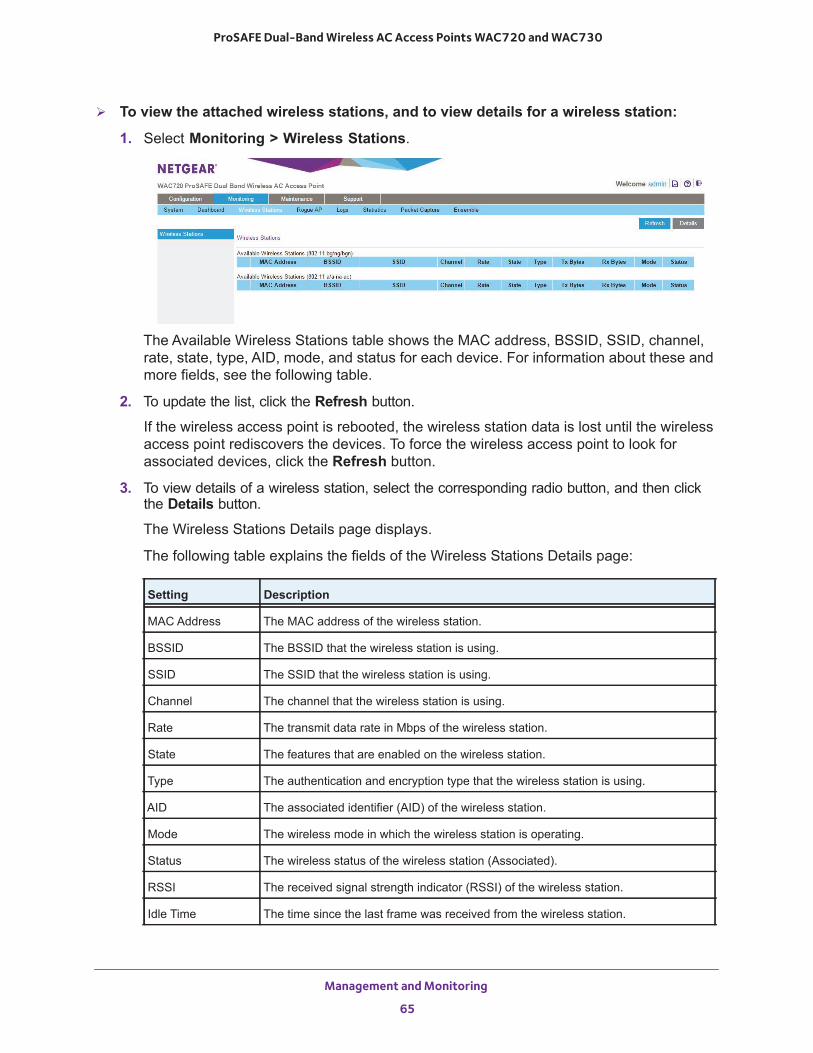
ProSAFE Dual-Band Wireless AC Access Points WAC720 and WAC730
To view the attached wireless stations, and to view details for a wireless station:
1. Select Monitoring > Wireless Stations.
The Available Wireless Stations table shows the MAC address, BSSID, SSID, channel, rate, state, type, AID, mode, and status for each device. For information about these and more fields, see the following table.
2. To update the list, click the Refresh button.
If the wireless access point is rebooted, the wireless station data is lost until the wireless access point rediscovers the devices. To force the wireless access point to look for associated devices, click the Refresh button.
3. To view details of a wireless station, select the corresponding radio button, and then click the Details button.
The Wireless Stations Details page displays.
The following table explains the fields of the Wireless Stations Details page:
Setting Description
MAC Address The MAC address of the wireless station.
BSSID The BSSID that the wireless station is using.
SSID The SSID that the wireless station is using.
Channel The channel that the wireless station is using.
Rate The transmit data rate in Mbps of the wireless station.
State The features that are enabled on the wireless station.
Type The authentication and encryption type that the wireless station is using.
AID The associated identifier (AID) of the wireless station.
Mode The wireless mode in which the wireless station is operating.
Status The wireless status of the wireless station (Associated).
RSSI The received signal strength indicator (RSSI) of the wireless station.
Idle Time The time since the last frame was received from the wireless station.
Management and Monitoring
65
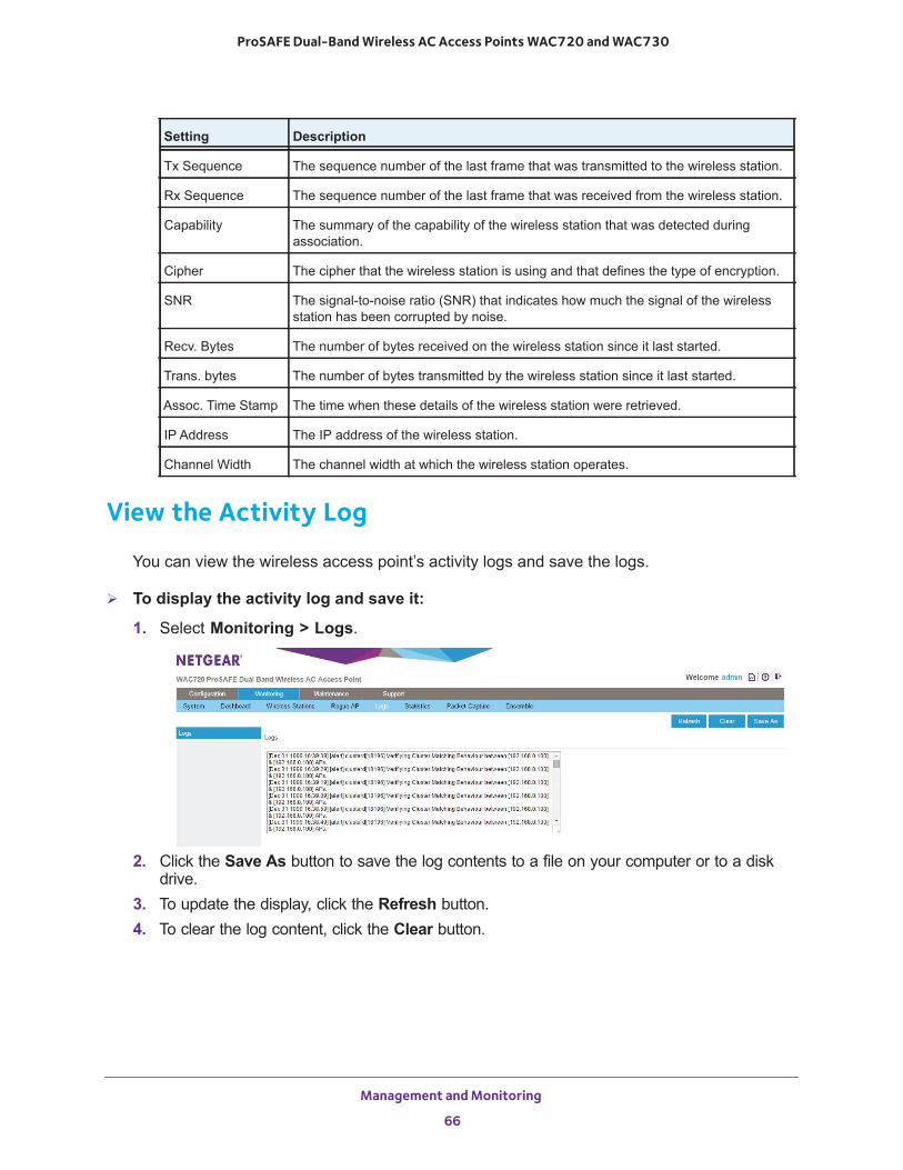
ProSAFE Dual-Band Wireless AC Access Points WAC720 and WAC730
View the Activity Log
You can view the wireless access point’s activity logs and save the logs.
To display the activity log and save it:
1. Select Monitoring > Logs.
2. Click the Save As button to save the log contents to a file on your computer or to a disk drive.
3. To update the display, click the Refresh button.4. To clear the log content, click the Clear button.
Tx Sequence The sequence number of the last frame that was transmitted to the wireless station.
Rx Sequence The sequence number of the last frame that was received from the wireless station.
Capability The summary of the capability of the wireless station that was detected during association.
Cipher The cipher that the wireless station is using and that defines the type of encryption.
SNR The signal-to-noise ratio (SNR) that indicates how much the signal of the wireless station has been corrupted by noise.
Recv. Bytes The number of bytes received on the wireless station since it last started.
Trans. bytes The number of bytes transmitted by the wireless station since it last started.
Assoc. Time Stamp The time when these details of the wireless station were retrieved.
IP Address The IP address of the wireless station.
Channel Width The channel width at which the wireless station operates.
Setting Description
Management and Monitoring
66
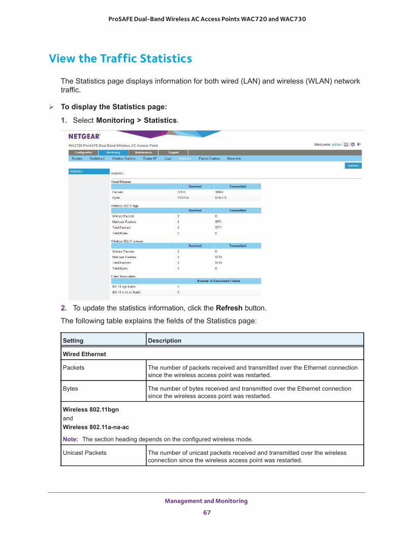
ProSAFE Dual-Band Wireless AC Access Points WAC720 and WAC730
View the Traffic Statistics
The Statistics page displays information for both wired (LAN) and wireless (WLAN) network traffic.
To display the Statistics page:
1. Select Monitoring > Statistics.
2. To update the statistics information, click the Refresh button.
The following table explains the fields of the Statistics page:
Setting Description
Wired Ethernet
Packets The number of packets received and transmitted over the Ethernet connection since the wireless access point was restarted.
Bytes The number of bytes received and transmitted over the Ethernet connection since the wireless access point was restarted.
Wireless 802.11bgnandWireless 802.11a-na-ac
Note: The section heading depends on the configured wireless mode.
Unicast Packets The number of unicast packets received and transmitted over the wireless connection since the wireless access point was restarted.
Management and Monitoring
67
ProSAFE Dual-Band Wireless AC Access Points WAC720 and WAC730
Enable and Configure Ensemble Mode
An access point (AP) ensemble is a dynamic, configuration-aware group of APs in the same subnet of a network. Each ensemble can include up to 10 members, which must be of the same model. Only one ensemble per wireless network is supported. However, a network subnet can include multiple ensembles. Ensembles allow APs to share various configuration information, such as VAP settings and QoS queue parameters.
Ensemble members share the configuration of the dominant AP.
An ensemble can be formed between two APs if the following conditions are met:
• The APs are of the same model.• The APs use the same radio mode.• The APs are connected on the same bridged segment.• The ensemble names of the APs that are joining are the same.• Ensemble mode is enabled on both APs.
Broadcast Packets The number of broadcast packets received and transmitted over the wireless connection since the wireless access point was restarted.
Multicast Packets The number of multicast packets received and transmitted over the wireless connection since the wireless access point was restarted.
Total Packets The total number of packets received and transmitted over the wireless connection since the wireless access point was restarted.
Total Bytes The total number of bytes received and transmitted over the wireless connection since the wireless access point was restarted.
Client Association
802.11bgn Radio,802.11a-na-ac Radio
The number of associated clients connected to the radio in the configured wireless modes.
Setting Description
Management and Monitoring
68
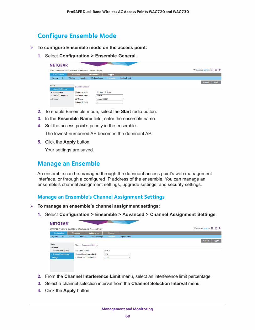
ProSAFE Dual-Band Wireless AC Access Points WAC720 and WAC730
Configure Ensemble Mode
To configure Ensemble mode on the access point:
1. Select Configuration > Ensemble General.
2. To enable Ensemble mode, select the Start radio button.3. In the Ensemble Name field, enter the ensemble name.4. Set the access point’s priority in the ensemble.
The lowest-numbered AP becomes the dominant AP.
5. Click the Apply button.
Your settings are saved.
Manage an EnsembleAn ensemble can be managed through the dominant access point’s web management interface, or through a configured IP address of the ensemble. You can manage an ensemble’s channel assignment settings, upgrade settings, and security settings.
Manage an Ensemble’s Channel Assignment Settings
To manage an ensemble’s channel assignment settings:
1. Select Configuration > Ensemble > Advanced > Channel Assignment Settings.
2. From the Channel Interference Limit menu, select an interference limit percentage.3. Select a channel selection interval from the Channel Selection Interval menu.4. Click the Apply button.
Management and Monitoring
69
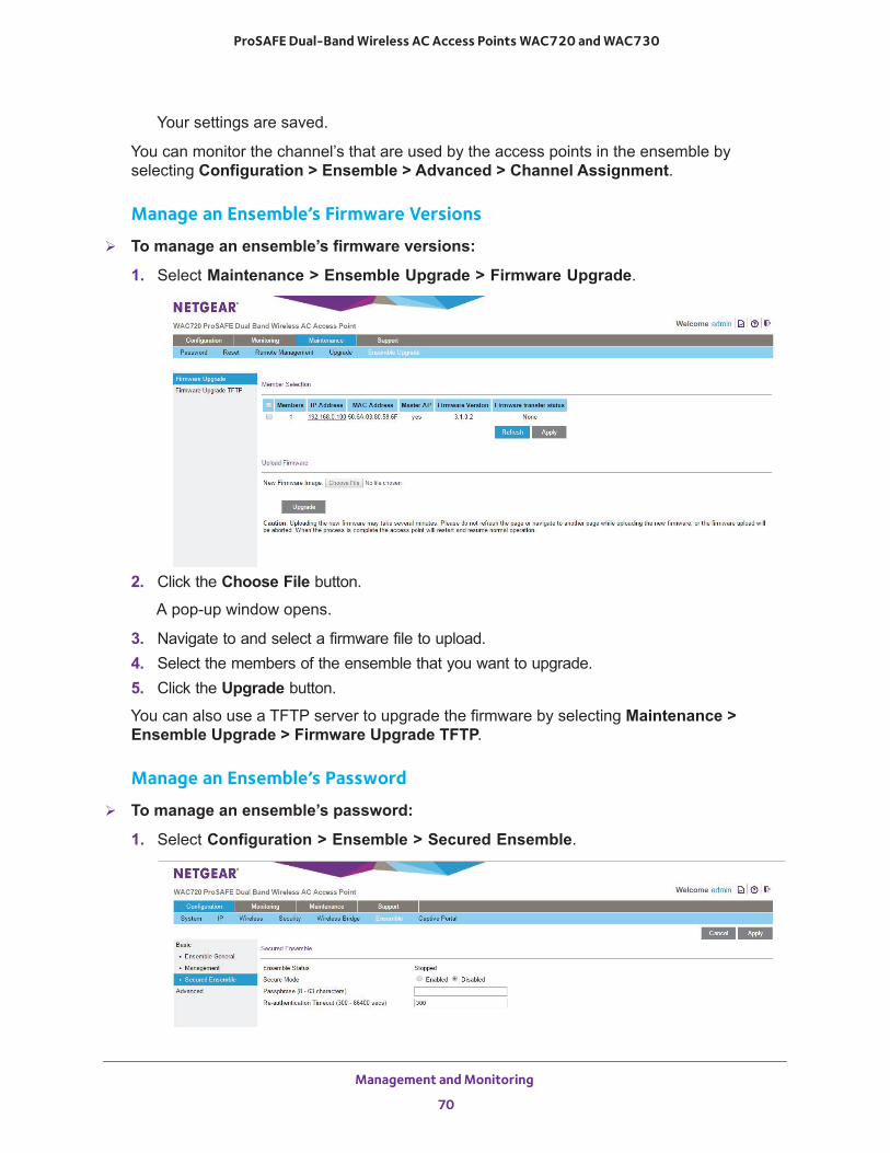
ProSAFE Dual-Band Wireless AC Access Points WAC720 and WAC730
Your settings are saved.
You can monitor the channel’s that are used by the access points in the ensemble by selecting Configuration > Ensemble > Advanced > Channel Assignment.
Manage an Ensemble’s Firmware Versions
To manage an ensemble’s firmware versions:
1. Select Maintenance > Ensemble Upgrade > Firmware Upgrade.
2. Click the Choose File button.
A pop-up window opens.
3. Navigate to and select a firmware file to upload.4. Select the members of the ensemble that you want to upgrade.5. Click the Upgrade button.
You can also use a TFTP server to upgrade the firmware by selecting Maintenance > Ensemble Upgrade > Firmware Upgrade TFTP.
Manage an Ensemble’s Password
To manage an ensemble’s password:
1. Select Configuration > Ensemble > Secured Ensemble.
Management and Monitoring
70
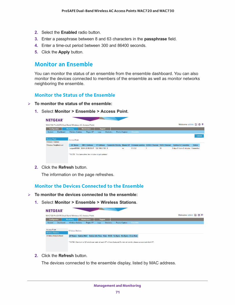
ProSAFE Dual-Band Wireless AC Access Points WAC720 and WAC730
2. Select the Enabled radio button.3. Enter a passphrase between 8 and 63 characters in the passphrase field.4. Enter a time-out period between 300 and 86400 seconds.5. Click the Apply button.
Monitor an EnsembleYou can monitor the status of an ensemble from the ensemble dashboard. You can also monitor the devices connected to members of the ensemble as well as monitor networks neighboring the ensemble.
Monitor the Status of the Ensemble
To monitor the status of the ensemble:
1. Select Monitor > Ensemble > Access Point.
2. Click the Refresh button.
The information on the page refreshes.
Monitor the Devices Connected to the Ensemble
To monitor the devices connected to the ensemble:
1. Select Monitor > Ensemble > Wireless Stations.
2. Click the Refresh button.
The devices connected to the ensemble display, listed by MAC address.
Management and Monitoring
71
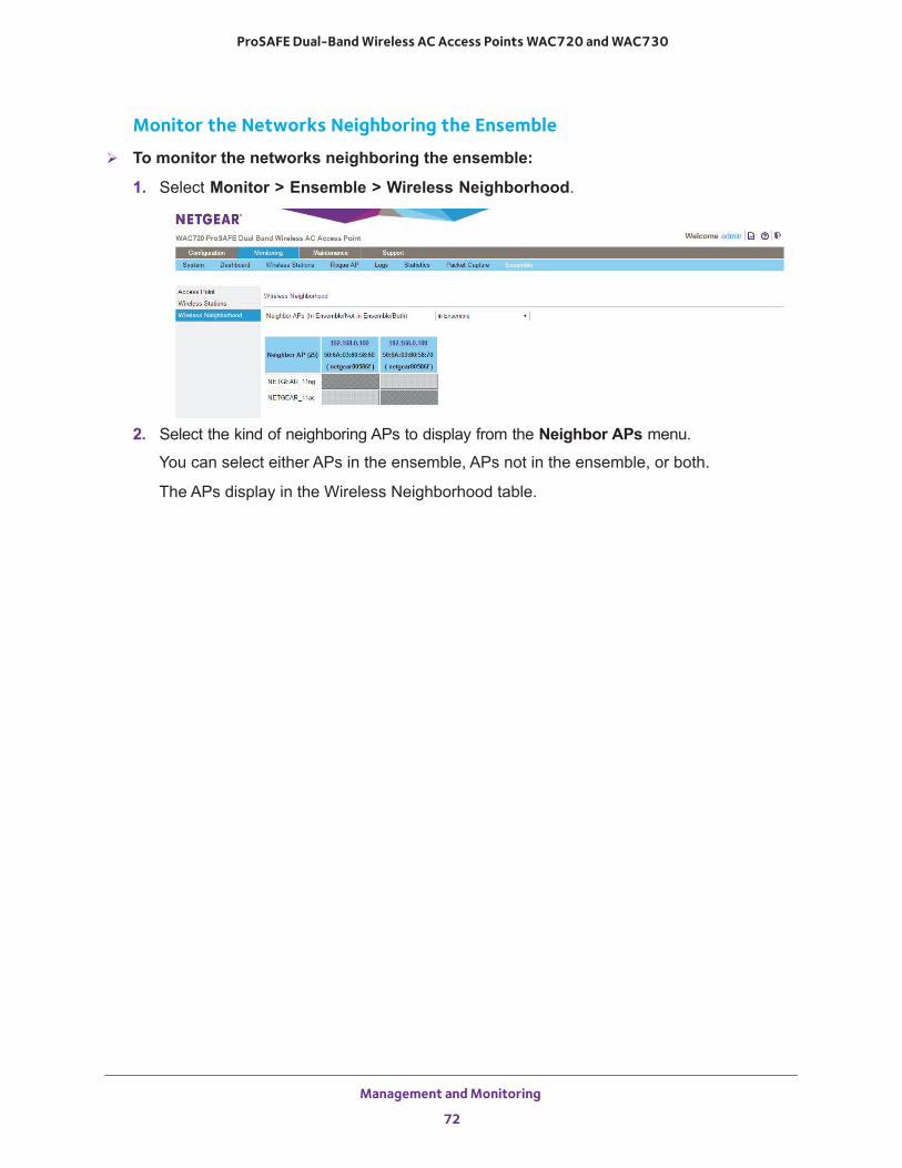
ProSAFE Dual-Band Wireless AC Access Points WAC720 and WAC730
Monitor the Networks Neighboring the Ensemble
To monitor the networks neighboring the ensemble:
1. Select Monitor > Ensemble > Wireless Neighborhood.
2. Select the kind of neighboring APs to display from the Neighbor APs menu.
You can select either APs in the ensemble, APs not in the ensemble, or both.
The APs display in the Wireless Neighborhood table.
Management and Monitoring
72
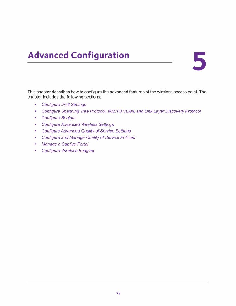
5
5. Advanced ConfigurationThis chapter describes how to configure the advanced features of the wireless access point. The chapter includes the following sections:
• Configure IPv6 Settings• Configure Spanning Tree Protocol, 802.1Q VLAN, and Link Layer Discovery Protocol• Configure Bonjour• Configure Advanced Wireless Settings• Configure Advanced Quality of Service Settings• Configure and Manage Quality of Service Policies• Manage a Captive Portal• Configure Wireless Bridging
73
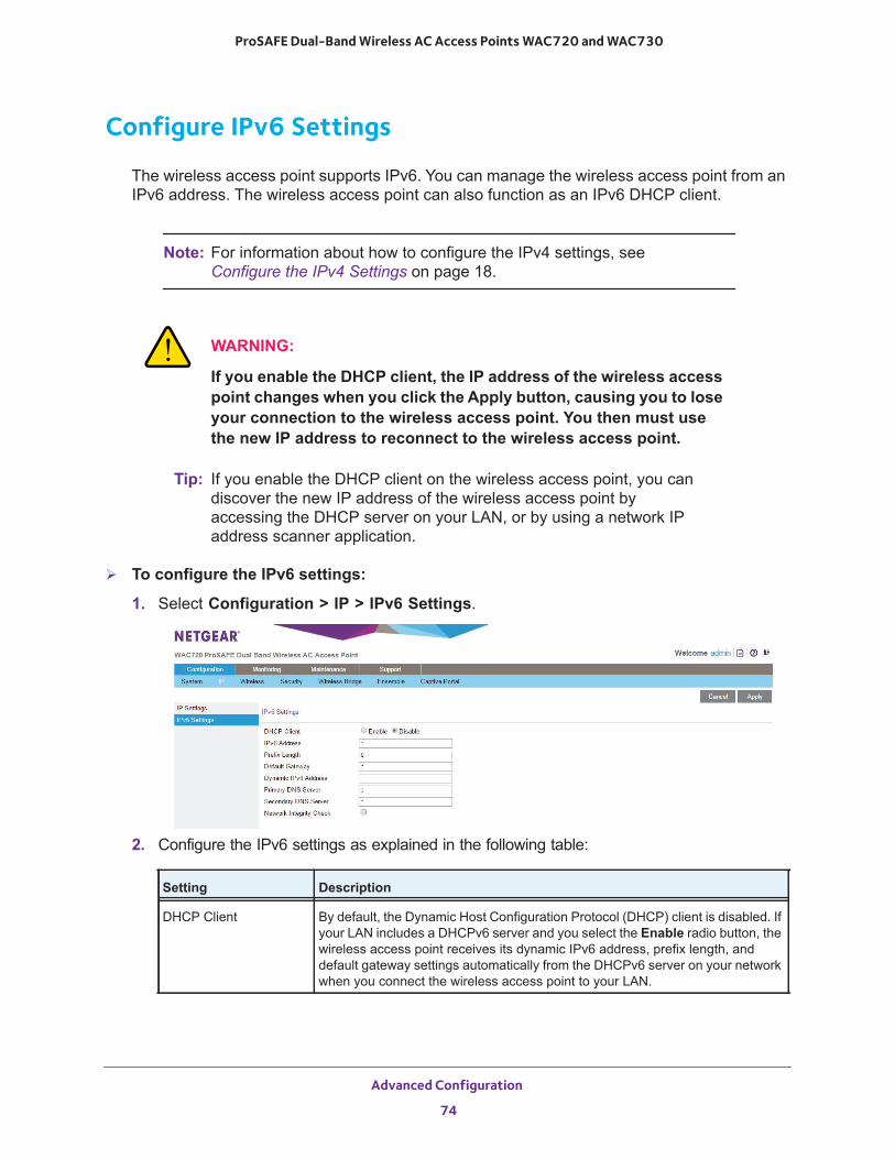
ProSAFE Dual-Band Wireless AC Access Points WAC720 and WAC730
Configure IPv6 Settings
The wireless access point supports IPv6. You can manage the wireless access point from an IPv6 address. The wireless access point can also function as an IPv6 DHCP client.
Note: For information about how to configure the IPv4 settings, see Configure the IPv4 Settings on page 18.
WARNING:
If you enable the DHCP client, the IP address of the wireless access point changes when you click the Apply button, causing you to lose your connection to the wireless access point. You then must use the new IP address to reconnect to the wireless access point.
Tip: If you enable the DHCP client on the wireless access point, you can discover the new IP address of the wireless access point by accessing the DHCP server on your LAN, or by using a network IP address scanner application.
To configure the IPv6 settings:
1. Select Configuration > IP > IPv6 Settings.
2. Configure the IPv6 settings as explained in the following table:
Setting Description
DHCP Client By default, the Dynamic Host Configuration Protocol (DHCP) client is disabled. If your LAN includes a DHCPv6 server and you select the Enable radio button, the wireless access point receives its dynamic IPv6 address, prefix length, and default gateway settings automatically from the DHCPv6 server on your network when you connect the wireless access point to your LAN.
Advanced Configuration
74
ProSAFE Dual-Band Wireless AC Access Points WAC720 and WAC730
3. Click the Apply button.
Your settings are saved.
Configure Spanning Tree Protocol, 802.1Q VLAN, andLink Layer Discovery Protocol
As part of the advanced system configuration, you can enable the Spanning Tree Protocol (STP), configure the VLANs, and enable Ethernet Link Layer Discovery Protocol (LLDP) as described in the following sections:
• Configure STP and VLANs• Configure Ethernet LLDP
Configure STP and VLANsSTP provides network traffic optimization in locations where multiple wireless access points are active by preventing path redundancy. If your location includes more than one active wireless access point, we recommend that you enable STP.
The 802.1Q VLAN protocol on the wireless access point logically separates traffic on the same physical network. The wireless access point supports the following types of VLANs:
• Untagged VLAN. When the wireless access point sends frames that are associated with the untagged VLAN from its Ethernet interface, those frames are untagged. When the wireless access point receives untagged frames over its Ethernet interface, those frames are assigned to the untagged VLAN.
IPv6 Address Enter the IP address of your wireless access point. The default IP address is 2001::21c:c0ff:fe69. To change the address, enter an unused IPv6 address from the address range used on your LAN.
Prefix Length Enter the prefix length for the IPv6 address. The default prefix length us 64.
Default Gateway Enter the IPv6 address of the ISP gateway to which the wireless access point connects.
Dynamic IPv6 Address The dynamic IPv6 address that is assigned by the DHCPv6 server on your network. This address does not overwrite the address in the IPv6 Address field.
Primary DNS Server Enter the IP address of the primary and secondary DNS servers. A DNS server is a host on the Internet that translates Internet names (such as www.netgear.com) to numeric IP addresses. Typically your ISP transfers the IP address of one or two DNS servers to your wireless access point during login. If the ISP does not transfer an address, you must obtain it from the ISP and enter it manually in this field.
Secondary DNS Server
Network Integrity Check Select this check box to validate that the upstream link is active before allowing wireless associations. Ensure that the default gateway is configured.
Setting Description
Advanced Configuration
75
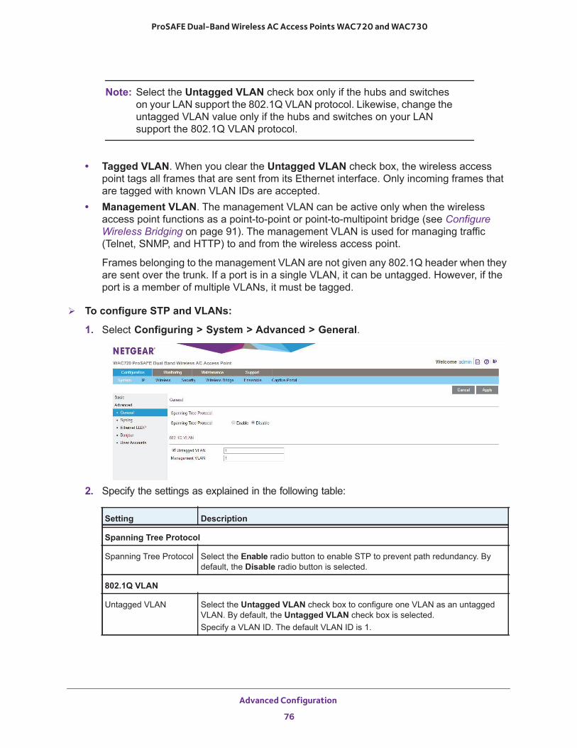
ProSAFE Dual-Band Wireless AC Access Points WAC720 and WAC730
Note: Select the Untagged VLAN check box only if the hubs and switches on your LAN support the 802.1Q VLAN protocol. Likewise, change the untagged VLAN value only if the hubs and switches on your LAN support the 802.1Q VLAN protocol.
• Tagged VLAN. When you clear the Untagged VLAN check box, the wireless access point tags all frames that are sent from its Ethernet interface. Only incoming frames that are tagged with known VLAN IDs are accepted.
• Management VLAN. The management VLAN can be active only when the wireless access point functions as a point-to-point or point-to-multipoint bridge (see Configure Wireless Bridging on page 91). The management VLAN is used for managing traffic (Telnet, SNMP, and HTTP) to and from the wireless access point.
Frames belonging to the management VLAN are not given any 802.1Q header when they are sent over the trunk. If a port is in a single VLAN, it can be untagged. However, if the port is a member of multiple VLANs, it must be tagged.
To configure STP and VLANs:
1. Select Configuring > System > Advanced > General.
2. Specify the settings as explained in the following table:
Setting Description
Spanning Tree Protocol
Spanning Tree Protocol Select the Enable radio button to enable STP to prevent path redundancy. By default, the Disable radio button is selected.
802.1Q VLAN
Untagged VLAN Select the Untagged VLAN check box to configure one VLAN as an untagged VLAN. By default, the Untagged VLAN check box is selected.Specify a VLAN ID. The default VLAN ID is 1.
Advanced Configuration
76
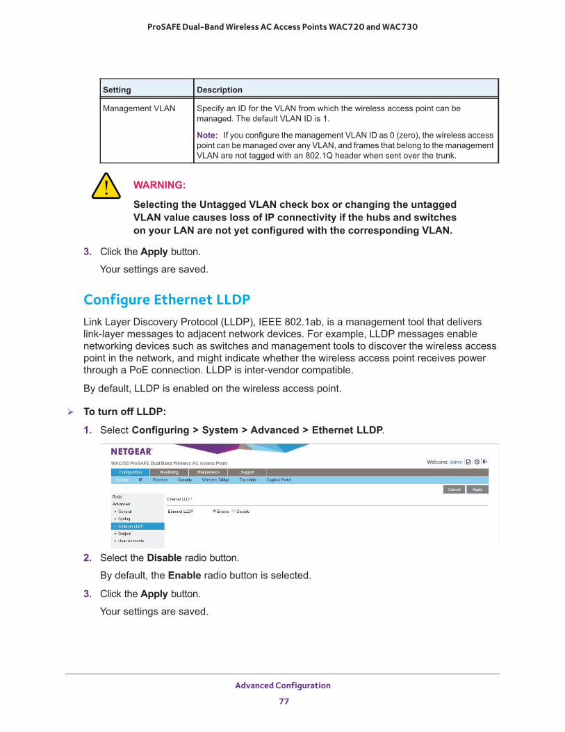
ProSAFE Dual-Band Wireless AC Access Points WAC720 and WAC730
WARNING:
Selecting the Untagged VLAN check box or changing the untagged VLAN value causes loss of IP connectivity if the hubs and switches on your LAN are not yet configured with the corresponding VLAN.
3. Click the Apply button.
Your settings are saved.
Configure Ethernet LLDPLink Layer Discovery Protocol (LLDP), IEEE 802.1ab, is a management tool that delivers link-layer messages to adjacent network devices. For example, LLDP messages enable networking devices such as switches and management tools to discover the wireless access point in the network, and might indicate whether the wireless access point receives power through a PoE connection. LLDP is inter-vendor compatible.
By default, LLDP is enabled on the wireless access point.
To turn off LLDP:
1. Select Configuring > System > Advanced > Ethernet LLDP.
2. Select the Disable radio button.
By default, the Enable radio button is selected.
3. Click the Apply button.
Your settings are saved.
Management VLAN Specify an ID for the VLAN from which the wireless access point can be managed. The default VLAN ID is 1.
Note: If you configure the management VLAN ID as 0 (zero), the wireless access point can be managed over any VLAN, and frames that belong to the management VLAN are not tagged with an 802.1Q header when sent over the trunk.
Setting Description
Advanced Configuration
77
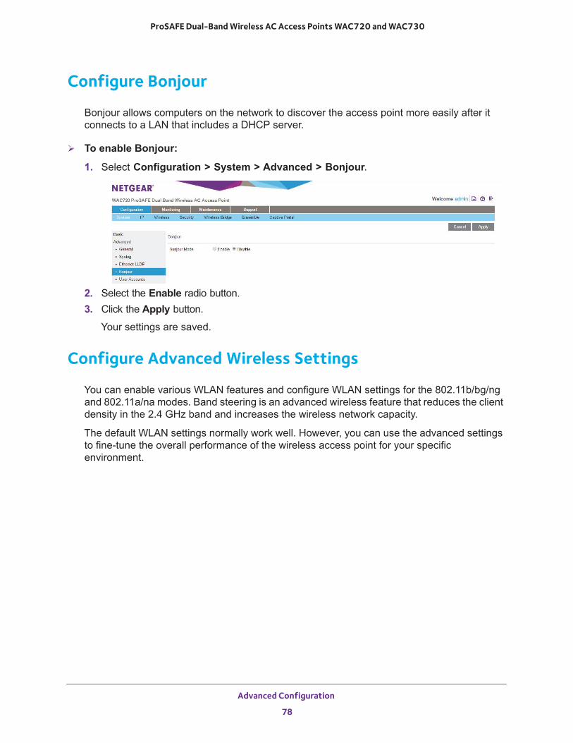
ProSAFE Dual-Band Wireless AC Access Points WAC720 and WAC730
Configure Bonjour
Bonjour allows computers on the network to discover the access point more easily after it connects to a LAN that includes a DHCP server.
To enable Bonjour:
1. Select Configuration > System > Advanced > Bonjour.
2. Select the Enable radio button.3. Click the Apply button.
Your settings are saved.
Configure Advanced Wireless Settings
You can enable various WLAN features and configure WLAN settings for the 802.11b/bg/ng and 802.11a/na modes. Band steering is an advanced wireless feature that reduces the client density in the 2.4 GHz band and increases the wireless network capacity.
The default WLAN settings normally work well. However, you can use the advanced settings to fine-tune the overall performance of the wireless access point for your specific environment.
Advanced Configuration
78
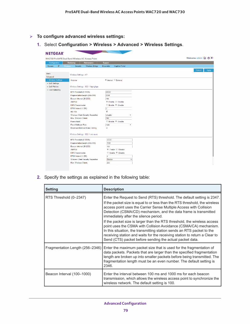
ProSAFE Dual-Band Wireless AC Access Points WAC720 and WAC730
To configure advanced wireless settings:
1. Select Configuration > Wireless > Advanced > Wireless Settings.
2. Specify the settings as explained in the following table:
Setting Description
RTS Threshold (0–2347) Enter the Request to Send (RTS) threshold. The default setting is 2347.If the packet size is equal to or less than the RTS threshold, the wireless access point uses the Carrier Sense Multiple Access with Collision Detection (CSMA/CD) mechanism, and the data frame is transmitted immediately after the silence period.If the packet size is larger than the RTS threshold, the wireless access point uses the CSMA with Collision Avoidance (CSMA/CA) mechanism. In this situation, the transmitting station sends an RTS packet to the receiving station and waits for the receiving station to return a Clear to Send (CTS) packet before sending the actual packet data.
Fragmentation Length (256–2346) Enter the maximum packet size that is used for the fragmentation of data packets. Packets that are larger than the specified fragmentation length are broken up into smaller packets before being transmitted. The fragmentation length must be an even number. The default setting is 2346.
Beacon Interval (100–1000) Enter the interval between 100 ms and 1000 ms for each beacon transmission, which allows the wireless access point to synchronize the wireless network. The default setting is 100.
Advanced Configuration
79
ProSAFE Dual-Band Wireless AC Access Points WAC720 and WAC730
3. Click the Apply button.
Your settings are saved.
AMPDU Select the Enable radio button to allow the aggregation of several MAC frames into a single large frame to achieve higher throughput. Enabling the aggregated MAC protocol data unit (A-MPDU) could lead to better network performance. By default, the Enable radio button is selected.
RIFS Transmission Select the Enable radio button to allow transmission of successive frames at different transmit powers. Enabling reduced interframe space (RIFS) could lead to better network performance. By default, the Disable radio button is selected.
DTIM Interval (1–255) Enter the delivery traffic indication message (DTIM) interval, also referred to as the data beacon rate, which indicates the beacon delivery traffic indication message period in multiples of beacon intervals. This value must be between 1 and 255. The default setting is 3.
Antenna Select one of the following radio buttons to specify the antenna:• Internal. Enables the internal antenna. This is the default setting.• External. Enables an optional external antenna or antennas.
802.11d
Note: This setting does not apply to the 802.11a/a-na-ac modes.
Select this check box to enable support for additional regulatory domains that are not in the current standard; support includes the addition of a country information element to beacons, probe requests, and probe responses. This check box is selected by default.
Wireless Client Security Separation
From the menu, select one of the following options:• Enable. Communication between wireless clients that are
associated to different virtual access points (VAPs) is blocked.• Disable. Communication between wireless clients that are
associated to different VAPs is allowed. This is the default setting.
Max. Wireless Clients Enter the maximum number of wireless clients that can simultaneously connect to the wireless access point at one time. The default setting is 128 clients.
Frame Burst Frame-burst support boosts the downstream throughput. It is disabled by default.
Fixed Multicast Rate Select the multicast traffic transmission rate you want the AP to support. The default value is Auto. For the 2.4 GHz radio, the Auto value is 1 Mbps. For the 5 GHz radio, the Auto value is 6 Mbps.
Broadcast/Multicast Rate Enabling multicast and broadcast rate limiting may improve overall network performance by limiting the number of packets transmitted across the network.By default the Multicast/Broadcast Rate Limiting option is disabled. The default and maximum rate limit setting is 50 packets per second. The default and maximum rate limit burst setting is 75 packets per second.
Setting Description
Advanced Configuration
80
ProSAFE Dual-Band Wireless AC Access Points WAC720 and WAC730
Configure Advanced Quality of Service Settings
For most networks, the default Quality of Service (QoS) queue settings work well. For information about how to configure basic QoS, see Configure Basic Wireless Quality of Service on page 46.
You can specify the settings on multiple queues for increased throughput and better performance of differentiated wireless traffic such as Voice over IP (VoIP), other types of audio, video, and streaming media, as well as traditional IP data.
The advanced QoS options on the wireless access point are as follows:
• AP EDCA parameters. Specify the access point (AP) Enhanced Distributed Channel Access (EDCA) settings for different types of data transmitted from the wireless access point to wireless clients.
• Station EDCA parameters. Specify the station EDCA parameters for different types of data transmitted from the wireless clients to the wireless access point. If WMM is disabled, you cannot configure the Station EDCA parameters. (For information about how to enable WMM, see Configure Basic Wireless Quality of Service on page 46.)
When you configure the EDCA settings, the wireless access point can leverage existing information in the IP packet header that is related to the Type of Service (ToS). The wireless access point examines the ToS field in the headers of all packets that it processes. Based on the value in a packet’s ToS field, the wireless access point prioritizes the packet for transmission by assigning it to one of the queues. A different type of data is associated with each queue. You can configure how the wireless access point treats each queue.
The queues defined for different types of data transmitted from AP-to-station and station-to-AP are as follows:
• Data 0 (Best Effort). Medium priority queue, medium throughput and delay. Most traditional IP data is sent to this queue.
• Data 1 (Background). Lowest priority queue, high throughput. Bulk data that requires maximum throughput and is not time-sensitive is sent to this queue (FTP data, for example).
• Data 2 (Video). Highest priority queue, minimum delay. Time-sensitive video data is automatically sent to this queue.
• Data 3 (Voice). Highest priority queue, minimum delay. Time-sensitive data such as VoIP and streaming media are automatically sent to this queue.
Advanced Configuration
81
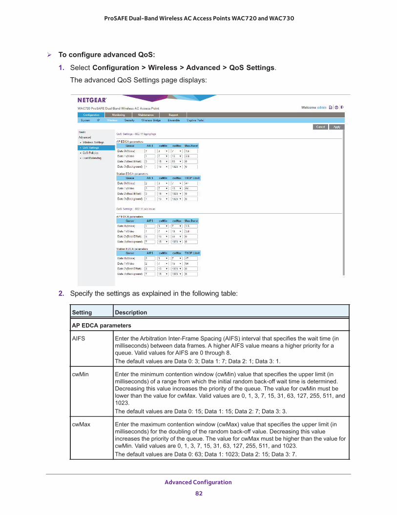
ProSAFE Dual-Band Wireless AC Access Points WAC720 and WAC730
To configure advanced QoS:
1. Select Configuration > Wireless > Advanced > QoS Settings.
The advanced QoS Settings page displays:
2. Specify the settings as explained in the following table:
Setting Description
AP EDCA parameters
AIFS Enter the Arbitration Inter-Frame Spacing (AIFS) interval that specifies the wait time (in milliseconds) between data frames. A higher AIFS value means a higher priority for a queue. Valid values for AIFS are 0 through 8. The default values are Data 0: 3; Data 1: 7; Data 2: 1; Data 3: 1.
cwMin Enter the minimum contention window (cwMin) value that specifies the upper limit (in milliseconds) of a range from which the initial random back-off wait time is determined. Decreasing this value increases the priority of the queue. The value for cwMin must be lower than the value for cwMax. Valid values are 0, 1, 3, 7, 15, 31, 63, 127, 255, 511, and 1023.The default values are Data 0: 15; Data 1: 15; Data 2: 7; Data 3: 3.
cwMax Enter the maximum contention window (cwMax) value that specifies the upper limit (in milliseconds) for the doubling of the random back-off value. Decreasing this value increases the priority of the queue. The value for cwMax must be higher than the value for cwMin. Valid values are 0, 1, 3, 7, 15, 31, 63, 127, 255, 511, and 1023. The default values are Data 0: 63; Data 1: 1023; Data 2: 15; Data 3: 7.
Advanced Configuration
82
ProSAFE Dual-Band Wireless AC Access Points WAC720 and WAC730
3. Click the Apply button.
Your settings are saved.
Configure and Manage Quality of Service Policies
The wireless access point lets you configure and apply QoS policies to wireless clients. In each QoS policy, you can specify multiple classifications (match clauses) and apply traffic to eight priority queues based on the following information in the Layer 2, Layer 3, Layer 3 IP headers, and Layer 4:
• IP precedence. Indicates the IP Type of Service (ToS) or precedence in the IP headers.• IP DSCP. Indicates the Differentiated Services Code Point (DSCP) marking in the IP
header.• IP protocol 119. Indicates the IP protocol field in the IP header with value 119.• 802.1P. Indicates the 3-bit Class of Service (CoS) field in the class header.
Max. Burst Enter the maximum burst value that specifies the maximum burst length (in microseconds) allowed for packet bursts on the wireless network. A packet burst is a collection of multiple frames transmitted without header information. Decreasing this value increases the priority of the queue. Valid values for maximum burst length are all multiples of 32 between 0 and 8192, inclusive of 0 and 8192.The default values are Data 0: 0; Data 1: 0; Data 2: 3008; Data 3: 1504.
Station EDCA parameters
AIFS Enter the Arbitration Inter-Frame Spacing (AIFS) interval that specifies the wait time (in milliseconds) between data frames. A higher AIFS value means a higher priority for a queue. Valid values for AIFS are 0 through 8. The default values are Data 0: 3; Data 1: 7; Data 2: 2; Data 3: 2.
cwMin Enter the minimum contention window (cwMin) value that specifies the upper limit (in milliseconds) of a range from which the initial random back-off wait time is determined. Decreasing this value increases the priority of the queue. The value for cwMin must be lower than the value for cwMax. Valid values are 0, 1, 3, 7, 15, 31, 63, 127, 255, 511, and 1023.The default values are Data 0: 15; Data 1: 15; Data 2: 7; Data 3: 3.
cwMax Enter the maximum contention window (cwMax) value that specifies the upper limit (in milliseconds) for the doubling of the random back-off value. Decreasing this value increases the priority of the queue. The value for cwMax must be higher than the value for cwMin. Valid values are 0, 1, 3, 7, 15, 31, 63, 127, 255, 511, and 1023. The default values are Data 0: 1023; Data 1: 1023; Data 2: 15; Data 3: 7.
TXOP Limit Enter the transmission opportunity (TXOP) value that specifies the time interval (in microseconds) in which a client station can initiate transmissions on the wireless medium (WM). Decreasing this value increases the priority of the queue. Valid values for TXOP Limit are all multiples of 32 between 0 and 8192, inclusive of 0 and 8192.The default values are Data 0: 0; Data 1: 0; Data 2: 3008; Data 3: 1504.
Setting Description
Advanced Configuration
83
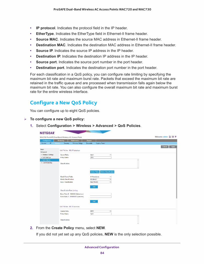
ProSAFE Dual-Band Wireless AC Access Points WAC720 and WAC730
• IP protocol. Indicates the protocol field in the IP header.• EtherType. Indicates the EtherType field in Ethernet-II frame header.• Source MAC. Indicates the source MAC address in Ethernet-II frame header.• Destination MAC. Indicates the destination MAC address in Ethernet-II frame header.• Source IP. Indicates the source IP address in the IP header.• Destination IP. Indicates the destination IP address in the IP header.• Source port. Indicates the source port number in the port header.• Destination port. Indicates the destination port number in the port header.
For each classification in a QoS policy, you can configure rate limiting by specifying the maximum bit rate and maximum burst rate. Packets that exceed the maximum bit rate are retained in the traffic queue and are processed when transmission falls again below the maximum bit rate. You can also configure the overall maximum bit rate and maximum burst rate for the entire wireless interface.
Configure a New QoS PolicyYou can configure up to eight QoS policies.
To configure a new QoS policy:
1. Select Configuration > Wireless > Advanced > QoS Policies.
2. From the Create Policy menu, select NEW.
If you did not yet set up any QoS policies, NEW is the only selection possible.
Advanced Configuration
84
ProSAFE Dual-Band Wireless AC Access Points WAC720 and WAC730
3. In the Policy Name field, enter a name for the new QoS policy.4. Specify a classification for the QoS policy as explained in the following table.
Note: Depending on your selection from the Match Frame Fields menu, Match Classifications appears either as a menu from which you must make a selection or as a field in which you must enter information.
Setting Description
Match Frame Fields and Match Classifications
IP DCSP From the Match Classifications menu, select the DSCP traffic class against which the information in the IP header must be matched:• Routine(0)• Priority(1)• Immediate(2)• Flash(3)• Flash Override(4)• Critic/CCP(5)• Inter Control(6)• Network Control(7)
IP Precedence From the Match Classifications menu, select the DSCP marking against which the information in the IP header must be matched:• Best Effort• Assured Forwarding - Class 1 Low• Assured Forwarding - Class 1 Medium• Assured Forwarding - Class 1 High• Assured Forwarding - Class 2 Low• Assured Forwarding - Class 2 Medium• Assured Forwarding - Class 2 High• Assured Forwarding - Class 3 Low• Assured Forwarding - Class 3 Medium• Assured Forwarding - Class 3 High• Assured Forwarding - Class 4 Low• Assured Forwarding - Class 4 Medium• Assured Forwarding - Class 4 High• Class Selector 1• Class Selector 2• Class Selector 3• Class Selector 4• Class Selector 5• Class Selector 6• Class Selector 7• Expedited Forwarding
IP Protocol119 Traffic is matched against value 119 in the IP protocol field in the IP header.
Advanced Configuration
85
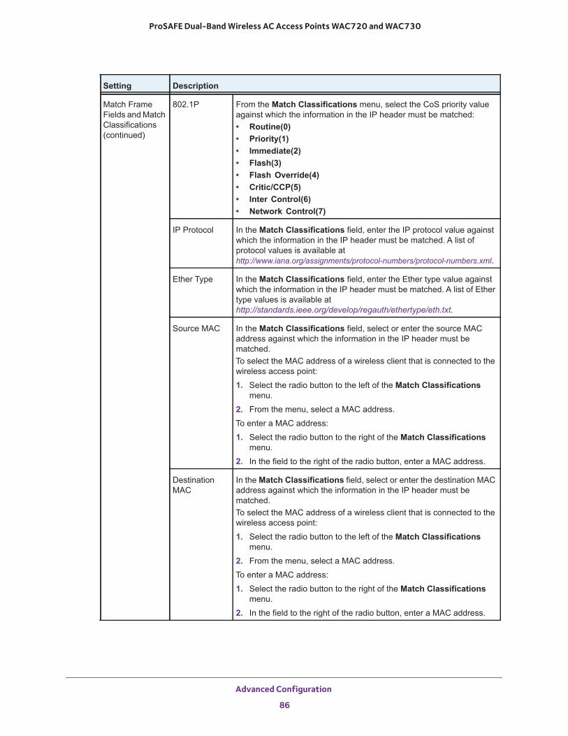
ProSAFE Dual-Band Wireless AC Access Points WAC720 and WAC730
Match Frame Fields and Match Classifications(continued)
802.1P From the Match Classifications menu, select the CoS priority value against which the information in the IP header must be matched:• Routine(0)• Priority(1)• Immediate(2)• Flash(3)• Flash Override(4)• Critic/CCP(5)• Inter Control(6)• Network Control(7)
IP Protocol In the Match Classifications field, enter the IP protocol value against which the information in the IP header must be matched. A list of protocol values is available at http://www.iana.org/assignments/protocol-numbers/protocol-numbers.xml.
Ether Type In the Match Classifications field, enter the Ether type value against which the information in the IP header must be matched. A list of Ether type values is available at http://standards.ieee.org/develop/regauth/ethertype/eth.txt.
Source MAC In the Match Classifications field, select or enter the source MAC address against which the information in the IP header must be matched. To select the MAC address of a wireless client that is connected to the wireless access point:
1. Select the radio button to the left of the Match Classifications menu.
2. From the menu, select a MAC address.
To enter a MAC address:
1. Select the radio button to the right of the Match Classifications menu.
2. In the field to the right of the radio button, enter a MAC address.
Destination MAC
In the Match Classifications field, select or enter the destination MAC address against which the information in the IP header must be matched. To select the MAC address of a wireless client that is connected to the wireless access point:
1. Select the radio button to the left of the Match Classifications menu.
2. From the menu, select a MAC address.
To enter a MAC address:
1. Select the radio button to the right of the Match Classifications menu.
2. In the field to the right of the radio button, enter a MAC address.
Setting Description
Advanced Configuration
86
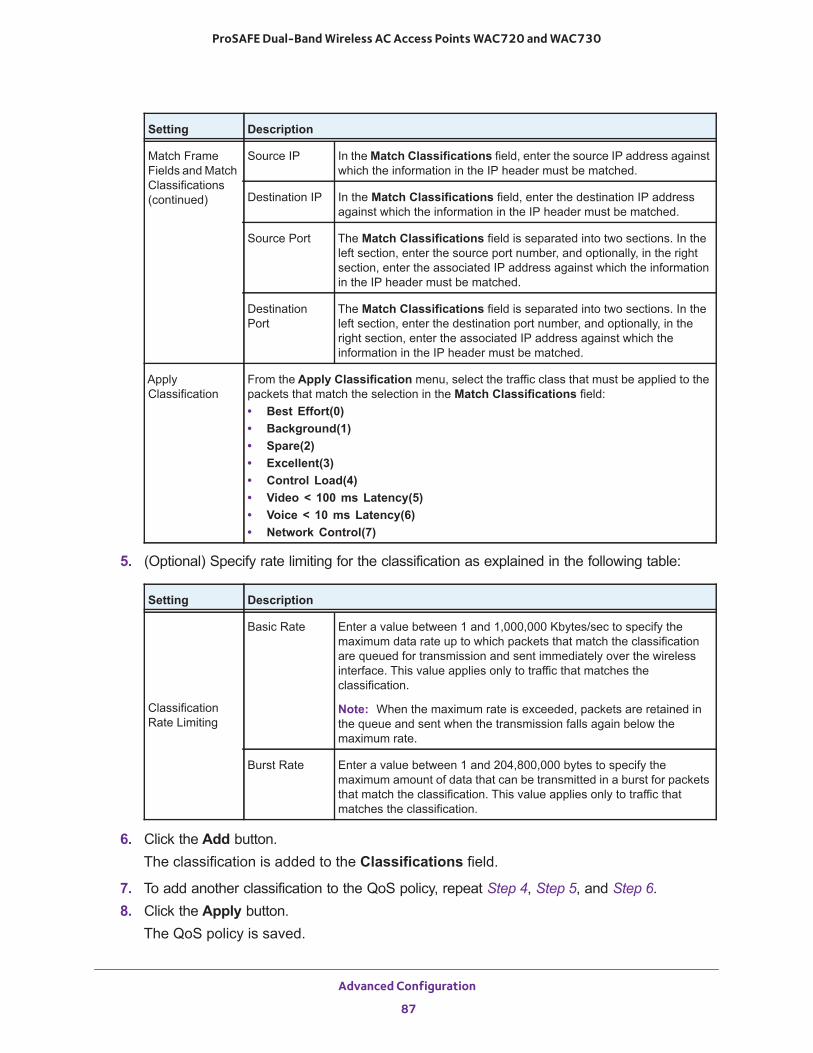
ProSAFE Dual-Band Wireless AC Access Points WAC720 and WAC730
5. (Optional) Specify rate limiting for the classification as explained in the following table:
6. Click the Add button.The classification is added to the Classifications field.
7. To add another classification to the QoS policy, repeat Step 4, Step 5, and Step 6.8. Click the Apply button.
The QoS policy is saved.
Match Frame Fields and Match Classifications(continued)
Source IP In the Match Classifications field, enter the source IP address against which the information in the IP header must be matched.
Destination IP In the Match Classifications field, enter the destination IP address against which the information in the IP header must be matched.
Source Port The Match Classifications field is separated into two sections. In the left section, enter the source port number, and optionally, in the right section, enter the associated IP address against which the information in the IP header must be matched.
Destination Port
The Match Classifications field is separated into two sections. In the left section, enter the destination port number, and optionally, in the right section, enter the associated IP address against which the information in the IP header must be matched.
Apply Classification
From the Apply Classification menu, select the traffic class that must be applied to the packets that match the selection in the Match Classifications field:• Best Effort(0)• Background(1)• Spare(2)• Excellent(3)• Control Load(4)• Video < 100 ms Latency(5)• Voice < 10 ms Latency(6)• Network Control(7)
Setting Description
Classification Rate Limiting
Basic Rate Enter a value between 1 and 1,000,000 Kbytes/sec to specify the maximum data rate up to which packets that match the classification are queued for transmission and sent immediately over the wireless interface. This value applies only to traffic that matches the classification.
Note: When the maximum rate is exceeded, packets are retained in the queue and sent when the transmission falls again below the maximum rate.
Burst Rate Enter a value between 1 and 204,800,000 bytes to specify the maximum amount of data that can be transmitted in a burst for packets that match the classification. This value applies only to traffic that matches the classification.
Setting Description
Advanced Configuration
87

ProSAFE Dual-Band Wireless AC Access Points WAC720 and WAC730
Note: Rate limiting for the wireless interface is an optional setting that applies to all traffic on the wireless interface. Unlike classification rate limiting, which you can specify for each classification, rate limiting for the wireless interface you must specify only once.
Modify a QoS Policy
To modify a QoS policy:
1. Select Configuration > Wireless > Advanced > QoS Policies.
The QoS Policies page displays.
2. From the Create Policy menu, select the policy that you want to modify.3. To modify a classification, you must delete the classification and add a new classification:
a. In the Classification field, select the old classification.b. Click the Delete Classification button.c. Add a new classification.
For information about how to add a classification, see Step 4 through Step 6 in the procedure to configure a new QoS policy.
4. To change the name of the policy, in the Policy Name field, enter a new name for the QoS policy.
5. Click the Apply button.
Your settings are saved.
Delete a QoS Policy
To delete a QoS policy:
1. Select Configuration > Wireless > Advanced > QoS Policies.
The QoS Policies page displays.
2. From the Create Policy menu, select the policy that you want to delete.3. Click the Delete Policy button.4. Click the Apply button.
Your settings are saved.
Advanced Configuration
88
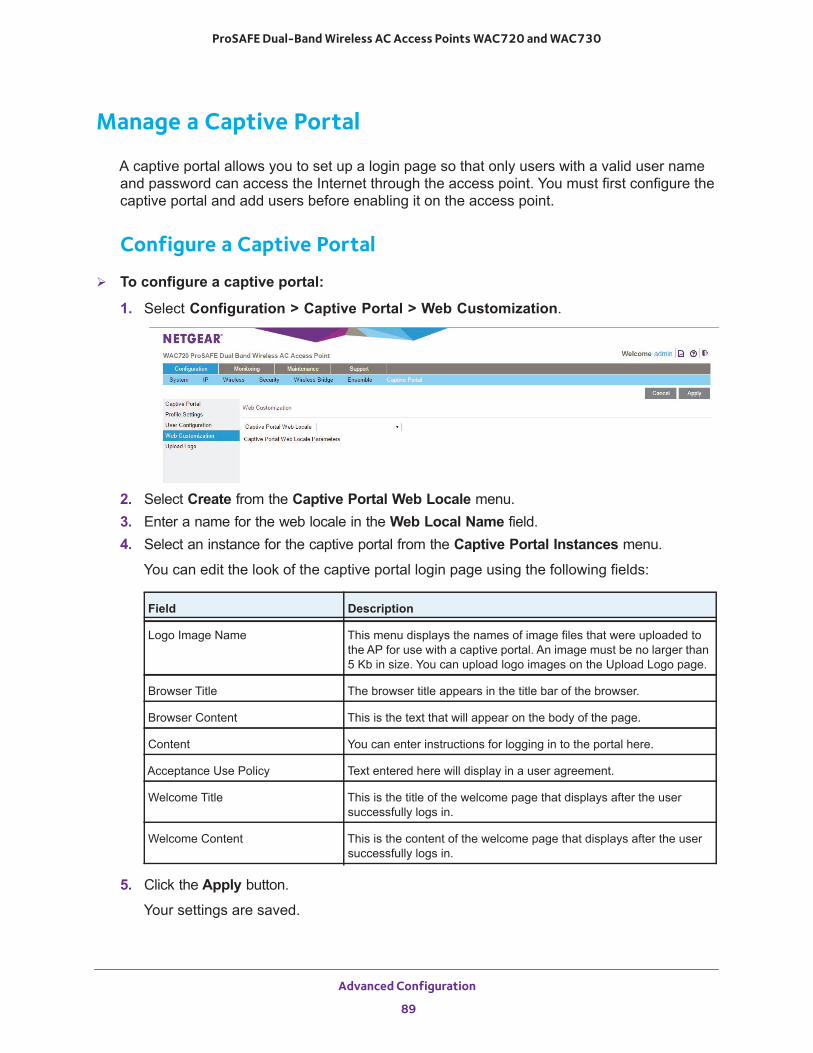
ProSAFE Dual-Band Wireless AC Access Points WAC720 and WAC730
Manage a Captive Portal
A captive portal allows you to set up a login page so that only users with a valid user name and password can access the Internet through the access point. You must first configure the captive portal and add users before enabling it on the access point.
Configure a Captive Portal
To configure a captive portal:
1. Select Configuration > Captive Portal > Web Customization.
2. Select Create from the Captive Portal Web Locale menu.3. Enter a name for the web locale in the Web Local Name field.4. Select an instance for the captive portal from the Captive Portal Instances menu.
You can edit the look of the captive portal login page using the following fields:
5. Click the Apply button.
Your settings are saved.
Field Description
Logo Image Name This menu displays the names of image files that were uploaded to the AP for use with a captive portal. An image must be no larger than 5 Kb in size. You can upload logo images on the Upload Logo page.
Browser Title The browser title appears in the title bar of the browser.
Browser Content This is the text that will appear on the body of the page.
Content You can enter instructions for logging in to the portal here.
Acceptance Use Policy Text entered here will display in a user agreement.
Welcome Title This is the title of the welcome page that displays after the user successfully logs in.
Welcome Content This is the content of the welcome page that displays after the user successfully logs in.
Advanced Configuration
89
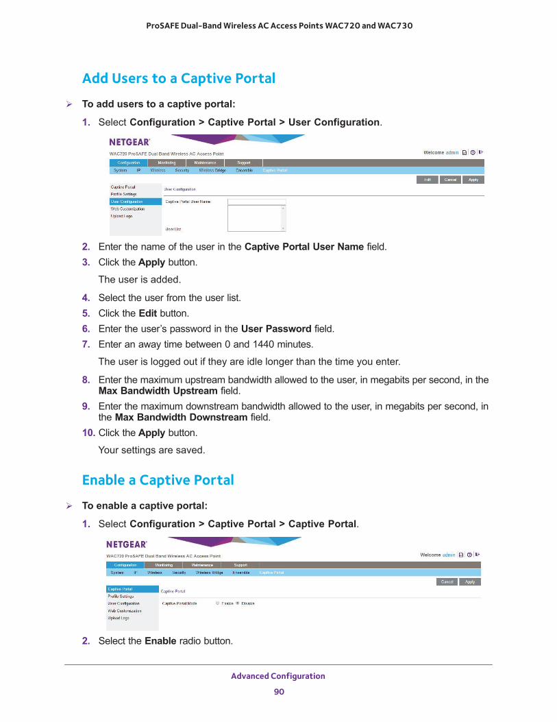
ProSAFE Dual-Band Wireless AC Access Points WAC720 and WAC730
Add Users to a Captive Portal
To add users to a captive portal:
1. Select Configuration > Captive Portal > User Configuration.
2. Enter the name of the user in the Captive Portal User Name field.3. Click the Apply button.
The user is added.
4. Select the user from the user list.5. Click the Edit button.6. Enter the user’s password in the User Password field.7. Enter an away time between 0 and 1440 minutes.
The user is logged out if they are idle longer than the time you enter.
8. Enter the maximum upstream bandwidth allowed to the user, in megabits per second, in the Max Bandwidth Upstream field.
9. Enter the maximum downstream bandwidth allowed to the user, in megabits per second, in the Max Bandwidth Downstream field.
10. Click the Apply button.
Your settings are saved.
Enable a Captive Portal
To enable a captive portal:
1. Select Configuration > Captive Portal > Captive Portal.
2. Select the Enable radio button.
Advanced Configuration
90
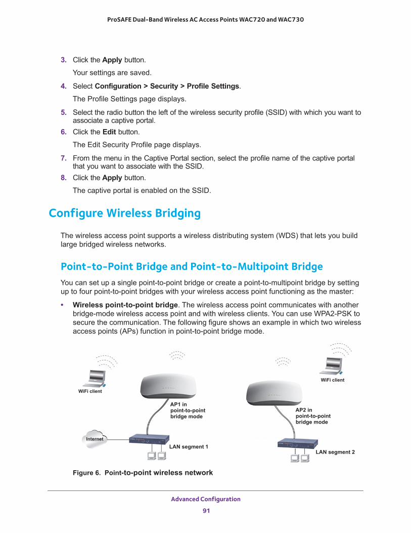
ProSAFE Dual-Band Wireless AC Access Points WAC720 and WAC730
3. Click the Apply button.
Your settings are saved.
4. Select Configuration > Security > Profile Settings.
The Profile Settings page displays.
5. Select the radio button the left of the wireless security profile (SSID) with which you want to associate a captive portal.
6. Click the Edit button.
The Edit Security Profile page displays.
7. From the menu in the Captive Portal section, select the profile name of the captive portal that you want to associate with the SSID.
8. Click the Apply button.
The captive portal is enabled on the SSID.
Configure Wireless Bridging
The wireless access point supports a wireless distributing system (WDS) that lets you build large bridged wireless networks.
Point-to-Point Bridge and Point-to-Multipoint BridgeYou can set up a single point-to-point bridge or create a point-to-multipoint bridge by setting up to four point-to-point bridges with your wireless access point functioning as the master:
• Wireless point-to-point bridge. The wireless access point communicates with another bridge-mode wireless access point and with wireless clients. You can use WPA2-PSK to secure the communication. The following figure shows an example in which two wireless access points (APs) function in point-to-point bridge mode.
Figure 6. Point-to-point wireless network
WiFi client
WiFi client
Internet
AP1 inpoint-to-pointbridge mode
AP2 inpoint-to-pointbridge mode
LAN segment 1LAN segment 2
Advanced Configuration
91
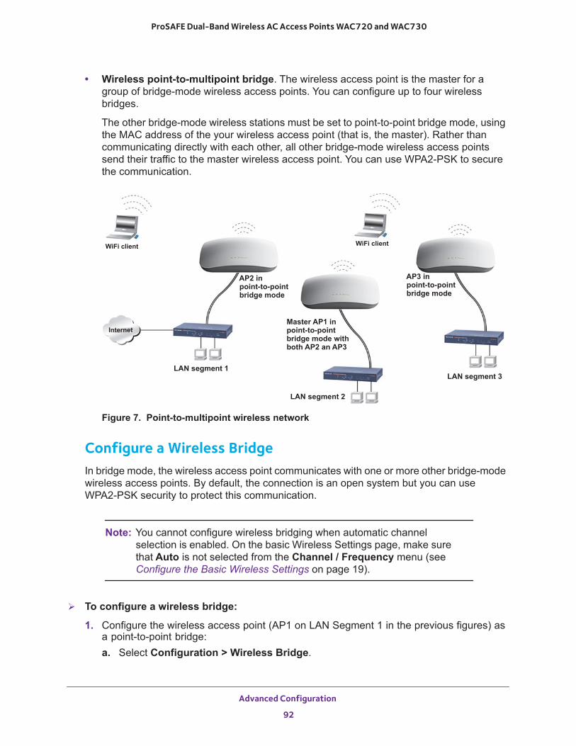
ProSAFE Dual-Band Wireless AC Access Points WAC720 and WAC730
• Wireless point-to-multipoint bridge. The wireless access point is the master for a group of bridge-mode wireless access points. You can configure up to four wireless bridges.
The other bridge-mode wireless stations must be set to point-to-point bridge mode, using the MAC address of the your wireless access point (that is, the master). Rather than communicating directly with each other, all other bridge-mode wireless access points send their traffic to the master wireless access point. You can use WPA2-PSK to secure the communication.
Figure 7. Point-to-multipoint wireless network
Configure a Wireless BridgeIn bridge mode, the wireless access point communicates with one or more other bridge-mode wireless access points. By default, the connection is an open system but you can use WPA2-PSK security to protect this communication.
Note: You cannot configure wireless bridging when automatic channel selection is enabled. On the basic Wireless Settings page, make sure that Auto is not selected from the Channel / Frequency menu (see Configure the Basic Wireless Settings on page 19).
To configure a wireless bridge:
1. Configure the wireless access point (AP1 on LAN Segment 1 in the previous figures) as a point-to-point bridge:a. Select Configuration > Wireless Bridge.
WiFi clientWiFi client
AP2 inpoint-to-pointbridge mode
Master AP1 inpoint-to-pointbridge mode with
AP3 inpoint-to-pointbridge mode
both AP2 an AP3
Internet
LAN segment 1
LAN segment 2
LAN segment 3
Advanced Configuration
92
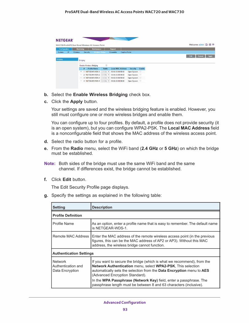
ProSAFE Dual-Band Wireless AC Access Points WAC720 and WAC730
b. Select the Enable Wireless Bridging check box.c. Click the Apply button.
Your settings are saved and the wireless bridging feature is enabled. However, you still must configure one or more wireless bridges and enable them.
You can configure up to four profiles. By default, a profile does not provide security (it is an open system), but you can configure WPA2-PSK. The Local MAC Address field is a nonconfigurable field that shows the MAC address of the wireless access point.
d. Select the radio button for a profile.e. From the Radio menu, select the WiFi band (2.4 GHz or 5 GHz) on which the bridge
must be established.
Note: Both sides of the bridge must use the same WiFi band and the same channel. If differences exist, the bridge cannot be established.
f. Click Edit button.
The Edit Security Profile page displays.
g. Specify the settings as explained in the following table:
Setting Description
Profile Definition
Profile Name As an option, enter a profile name that is easy to remember. The default name is NETGEAR-WDS-1.
Remote MAC Address Enter the MAC address of the remote wireless access point (in the previous figures, this can be the MAC address of AP2 or AP3). Without this MAC address, the wireless bridge cannot function.
Authentication Settings
Network Authentication andData Encryption
If you want to secure the bridge (which is what we recommend), from the Network Authentication menu, select WPA2-PSK, This selection automatically sets the selection from the Data Encryption menu to AES (Advanced Encryption Standard).In the WPA Passphrase (Network Key) field, enter a passphrase. The passphrase length must be between 8 and 63 characters (inclusive).
Advanced Configuration
93
ProSAFE Dual-Band Wireless AC Access Points WAC720 and WAC730
h. Click the Apply button.
Your settings are saved.
i. Click the Back button.
The Bridging page displays again.
2. Configure another wireless access point in point-to-point bridge mode.
Your access point must include the MAC address of the other wireless access point in its Remote MAC Address field, and the other way around, the other wireless access point must include the MAC address of your access point in its Remote MAC Address field.
Note: Both sides of the bridge must use the same WiFi band and the same channel. If differences exist, the bridge cannot be established.
3. Verify the following settings for both wireless access points:• Both wireless access points must operate in the same LAN network address range as
the LAN devices.• Both wireless access points must use the same channel, authentication mode, and
security settings.4. Go back to the Bridging page on your wireless access point and select the Enable check
box for the profile.5. Click the Apply button.
Your settings are saved.
6. Enable bridging on the other wireless access point.7. Verify connectivity across the LAN segments.
A computer on either LAN segment must be able to connect to the Internet and share files and printers of any other computers or servers on the other LAN segment.
8. To set up a point-to-multipoint WiFi network, repeat Step 1 through Step 7 for another profile and another wireless access point.
In point-to-multipoint WiFi network, your wireless access point becomes the master for all wireless bridges. For each wireless access point that you want the master to be able to connect to, you must configure a security profile with a unique name and the MAC address of the wireless access point. You can configure up to four such security profiles (NETGEAR-WDS-1, NETGEAR-WDS-2, and so on).
Note: You can extend the range of a wireless bridge with NETGEAR wireless antenna accessories.
Advanced Configuration
94
6
6. TroubleshootingThis chapter provides information about troubleshooting the wireless access point. After each problem description, instructions are given to help you diagnose and solve the problem. For the common problems listed, go to the section indicated.
• Is the wireless access point on?
Go to Troubleshoot the Basic Functions on page 96.
• Did I connected the wireless access point correctly?
Go to Troubleshoot the Basic Functions on page 96.
• I cannot access the Internet or the LAN.
Go to You Cannot Access the Internet or the LAN from a Wireless-Capable Computer on page 97.
• I cannot access the wireless access point from a browser.
Go to You Cannot Configure the Wireless Access Point from a Browser on page 98.
• A time-out occurs.
Go to When You Enter a URL or IP Address a Time-Out Error Occurs on page 99.
• Problems with the LAN connection occur.
Go to Troubleshoot a TCP/IP Network Using the Ping Utility on page 99.
• I cannot remember the wireless access point’s configuration password.
Go to Change the Administrator Password on page 57.
• I want to clear the configuration and start over again.
Go to Restore the Wireless Access Point to the Factory Default Settings on page 55.
• The date or time is not correct.
Go to Problems With Date and Time on page 101.
The wireless access point provides a packet capture tool that enables you to perform problem diagnoses. For information about how to use this tool, see Use the Packet Capture Tool on page 101.
95
ProSAFE Dual-Band Wireless AC Access Points WAC720 and WAC730
Troubleshoot the Basic Functions
The following sections describe how you can troubleshoot the basic functions of the wireless access point:
• Verify the Correct Sequence of Events at Startup• No LEDs Are Lit on the Wireless Access Point• The Active LED or the LAN LED Is Not Lit• The WLAN LED Does Not Light
Note: For descriptions of the LEDs, see Top Panel on page 7.
Verify the Correct Sequence of Events at Startup
After you turn on power to the wireless access point, check that the following sequence of events occurs:
• The Power/Test LED is first steady amber, then goes off, and then blinks green before turning steady green after about 45 seconds.
• The Active LED is lit or blinks green when Ethernet traffic is detected.• The LAN LED indicates the LAN speed: green for 1000 Mbps, amber for 100 Mbps, and
no light for 10 Mbps.• The WLAN LED is lit or blinks green when the wireless LAN (WLAN) is ready.
If any of these conditions does not occur, see the appropriate following section.
No LEDs Are Lit on the Wireless Access PointIt takes a few seconds for the Power LED to light. Wait a minute and check the Power LED status on the wireless access point. If the wireless access point is not receiving power, do the following:
• If you use one or more PoE switches to provide power to the wireless access point, check these items:- Make sure that the Ethernet cables between the wireless access point and the PoE
switches are correctly connected at both ends.- Make sure that the power cords of the PoE switches are plugged into working power
outlets or power strips.- Make sure that the PoE switches are functioning normally.
Troubleshooting
96
ProSAFE Dual-Band Wireless AC Access Points WAC720 and WAC730
• If you use a power cord to provide power to the wireless access point, check these items:- Make sure that the power cord is connected to the wireless access point.- Make sure that the power adapter is connected to a functioning power outlet. If it is in
a power strip, make sure that the power strip is turned on. If it is plugged directly into the wall, verify that it is not a switched outlet.
- Make sure that you are using the correct NETGEAR power adapter that is supplied with your wireless access point.
The Active LED or the LAN LED Is Not LitA hardware connection problem occurs. Check these items:
• Make sure that the cable connectors are securely plugged in at the wireless access point and the network device—hub, (PoE) switches, or router.
• Make sure that the connected device is turned on.• Make sure that the correct cable is used. Use a standard Category 5 Ethernet patch
cable. If the network device has Auto Uplink (MDI/MDIX) ports, you can use either a crossover cable or a normal patch cable.
The WLAN LED Does Not LightThe wireless access point’s antenna is not working. Check these items:
• If the WLAN LED remains off, either disconnect the cables to the PoE switches and then reconnect them again, or disconnect the adapter from its power source and then plug it in again.
• Make sure that optional external antennas are tightly connected to the wireless access point.
Contact NETGEAR technical support if the WLAN LED remains off.
You Cannot Access the Internet or the LAN from aWireless-Capable Computer
A configuration problem occurred. Check these items:
• Maybe you did not restart the computer with the wireless adapter to allow TCP/IP changes take effect. If so, restart the computer.
• The computer with the wireless adapter might not include the correct TCP/IP settings to communicate with the network. Restart the computer and check that TCP/IP is set up correctly for that network. In Windows, the usual setting for Network Properties is to obtain an IP address automatically.
• The wireless access point’s default values might not work with your network. Check the wireless access point’s default configuration against the configuration of other devices in your network.
Troubleshooting
97
ProSAFE Dual-Band Wireless AC Access Points WAC720 and WAC730
• Make sure that the SSID, network authentication, and data encryption settings of the computer with the wireless adapter are the same as those of the wireless access point.
• Ping the IP address of the wireless access point to verify that a wireless connection exists between the computer with the wireless adapter and the wireless access point. If the ping fails, check the network configuration (for the wireless access point, see Configure the IPv4 Settings on page 18).
• Ping the default gateway to verify that a path exists from the computer with the wireless adapter to the default gateway. If the ping fails, check the network configuration or call the Internet service provider (ISP).
You Cannot Configure the Wireless Access Point from a Browser
Check these items:
• The wireless access point is correctly installed, it is powered on, and LAN connections are okay. Check to see that the Active LED and LAN LED are on to verify that the Ethernet connection is okay.
• If your computer uses a fixed (static) IP address, ensure that it is using an IP address in the range of the wireless access point. The wireless access point’s default IP address is 192.168.0.100, and its subnet mask is 255.255.255.0, with DHCP disabled. Make sure that your network configuration settings are correct.
• If you are using the NetBIOS name of the wireless access point to connect, ensure that your computer and the wireless access point are on the same network segment or that your network includes a WINS server.
• If your computer is set to obtain an IP address automatically (DHCP client), restart it.• Make sure that Java, JavaScript, or ActiveX is enabled in your browser. If you are using
Internet Explorer, click the Refresh button to be sure that the Java applet is loaded.• Try quitting the browser, clearing the cache, deleting the cookies, and launching the
browser again.• Make sure that you are using the correct login information. The factory default login name
is admin, and the password is password. Make sure that Caps Lock is off when entering this information.
If the wireless access point does not save changes that you made in the web management interface, check the following:
• When entering configuration settings, be sure to click the Apply button before moving to another page or tab, or your changes are lost.
• Click the Refresh or Reload button in the web browser. The changes might occur, but the web browser might be caching the old configuration.
Troubleshooting
98
ProSAFE Dual-Band Wireless AC Access Points WAC720 and WAC730
When You Enter a URL or IP Address a Time-Out Error Occurs
A number of things could be causing this situation. Try the following troubleshooting steps:
• Check to see whether other computers on the LAN work correctly. If they do, ensure that your computer’s TCP/IP settings are correct. If you use a fixed (static) IP address, check the subnet mask, default gateway, DNS, and IP addresses of the wireless access point (see Configure the IPv4 Settings on page 18).
• If the computer is configured correctly but still not working, ensure that the wireless access point is connected and turned on. Access it and check its settings. If you cannot connect to the wireless access point, check the LAN and power connections.
• If the wireless access point is configured correctly, check your Internet connection (for example, your cable modem) to make sure that it is working correctly.
Troubleshoot a TCP/IP Network Using the Ping Utility
Most TCP/IP terminal devices and routers contain a ping utility that sends an echo request packet to the designated device. The device then responds with an echo reply. You can easily troubleshoot a TCP/IP network by using the ping utility in your computer, as described in the following sections:
• Test the LAN Path to Your Wireless Access Point• Test the Path from Your Computer to a Remote Device
Test the LAN Path to Your Wireless Access PointYou can ping the wireless access point from your computer to verify that the LAN path to your wireless access point is set up correctly.
To ping the wireless access point from a computer running Windows:
1. From the Windows toolbar, click the Start button, and select Run.2. In the field provided, type ping followed by the IP address of the wireless access point, as
in this example:
ping 192.168.0.1003. Click the OK button.
A message like the following one displays:
Pinging <IP address> with 32 bytes of data
If the path is working, you see this message:
Reply from < IP address >: bytes=32 time=NN ms TTL=xxx
Troubleshooting
99
ProSAFE Dual-Band Wireless AC Access Points WAC720 and WAC730
If the path is not working, you see this message:
Request timed out
If the path is not functioning correctly, one of the following problems could be occurring:
- Make sure that the Active LED and LAN LED are on. If one or both of these LEDs are off, follow the instructions in The Active LED or the LAN LED Is Not Lit on page 97.
- Check to see that the corresponding link LEDs are on for your network interface card and for the hub ports (if any) that are connected to your workstation and wireless access point.
• Wrong network configuration:- Verify that the Ethernet card driver software and TCP/IP software are both
installed and configured on your computer.- Verify that the IP address for your wireless access point and your workstation are
correct and that the addresses are on the same subnet.
Test the Path from Your Computer to a Remote DeviceAfter verifying that the LAN path works correctly, test the path from your computer to a remote device.
1. From the Windows toolbar, click the Start button, and select Run.2. In the Windows Run window, type
ping -n 10 <IP address>
where <IP address> is the IP address of a remote device such as the DNS server of your ISP.
If the path is functioning correctly, replies as in Test the LAN Path to Your Wireless Access Point on page 99 display. If you do not receive replies, do the following:
• Check to see that the IP address of your wireless access point is listed as the IP address of the default router in your computer. If the IP configuration of your computer is assigned by DHCP, this information is not visible in your computer’s Network Control Panel. Verify that the IP address of the wireless access point is listed as the IP address of the default router.
• Check to see that the network address of your computer (the portion of the IP address specified by the netmask) is different from the network address of the remote device.
• Check to see that your cable or DSL modem is connected and functioning.• If your ISP assigned a host name to your computer, enter that host name as the account
name on the basis General system settings page (see Configure Basic General System Settings and Time Settings on page 16).
Troubleshooting
100
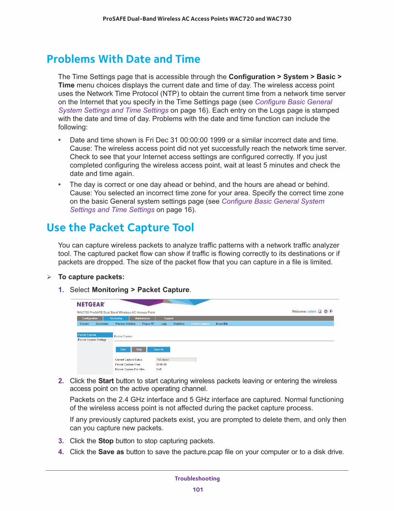
ProSAFE Dual-Band Wireless AC Access Points WAC720 and WAC730
Problems With Date and TimeThe Time Settings page that is accessible through the Configuration > System > Basic > Time menu choices displays the current date and time of day. The wireless access point uses the Network Time Protocol (NTP) to obtain the current time from a network time server on the Internet that you specify in the Time Settings page (see Configure Basic General System Settings and Time Settings on page 16). Each entry on the Logs page is stamped with the date and time of day. Problems with the date and time function can include the following:
• Date and time shown is Fri Dec 31 00:00:00 1999 or a similar incorrect date and time. Cause: The wireless access point did not yet successfully reach the network time server. Check to see that your Internet access settings are configured correctly. If you just completed configuring the wireless access point, wait at least 5 minutes and check the date and time again.
• The day is correct or one day ahead or behind, and the hours are ahead or behind. Cause: You selected an incorrect time zone for your area. Specify the correct time zone on the basic General system settings page (see Configure Basic General System Settings and Time Settings on page 16).
Use the Packet Capture ToolYou can capture wireless packets to analyze traffic patterns with a network traffic analyzer tool. The captured packet flow can show if traffic is flowing correctly to its destinations or if packets are dropped. The size of the packet flow that you can capture in a file is limited.
To capture packets:
1. Select Monitoring > Packet Capture.
2. Click the Start button to start capturing wireless packets leaving or entering the wireless access point on the active operating channel.Packets on the 2.4 GHz interface and 5 GHz interface are captured. Normal functioning of the wireless access point is not affected during the packet capture process.If any previously captured packets exist, you are prompted to delete them, and only then can you capture new packets.
3. Click the Stop button to stop capturing packets.4. Click the Save as button to save the pacture.pcap file on your computer or to a disk drive.
Troubleshooting
101
A
A. Supplemental InformationThis appendix provides factory default settings and technical specifications for the ProSAFE Dual-Band Wireless AC Access Points WAC720 and WAC730. The appendix includes the following sections:
• Technical Specifications • Factory Default Settings
102
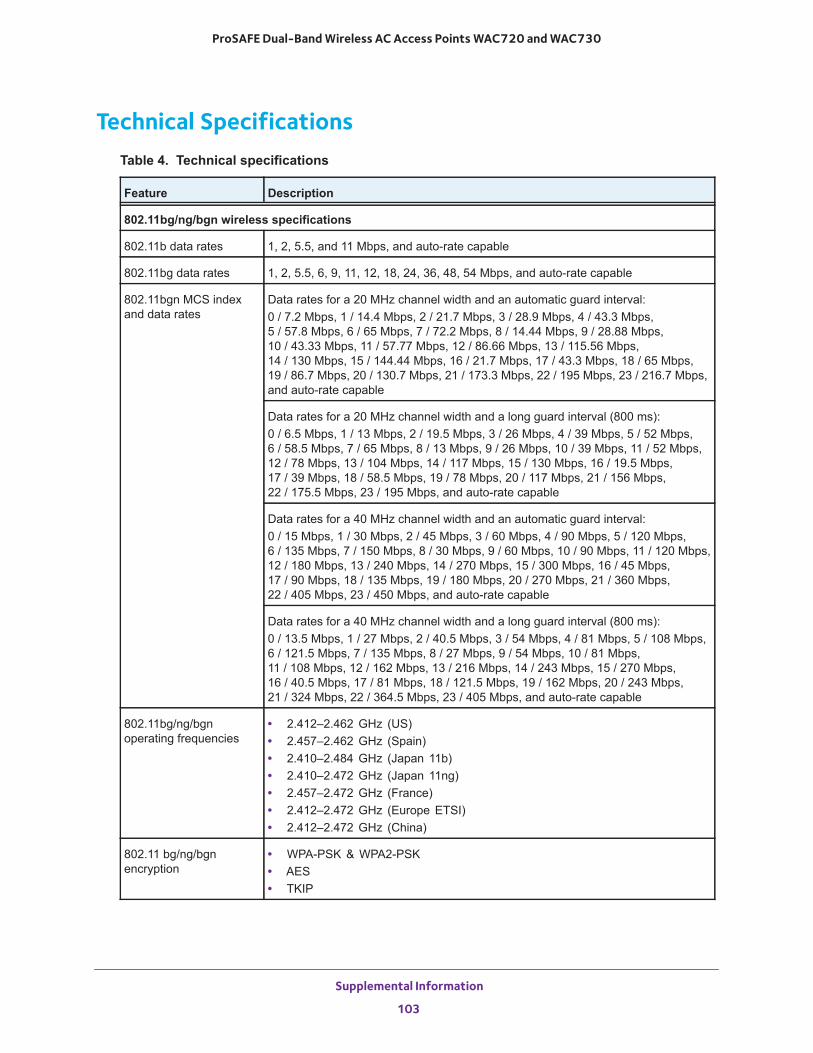
ProSAFE Dual-Band Wireless AC Access Points WAC720 and WAC730
Technical SpecificationsTable 4. Technical specifications
Feature Description
802.11bg/ng/bgn wireless specifications
802.11b data rates 1, 2, 5.5, and 11 Mbps, and auto-rate capable
802.11bg data rates 1, 2, 5.5, 6, 9, 11, 12, 18, 24, 36, 48, 54 Mbps, and auto-rate capable
802.11bgn MCS index and data rates
Data rates for a 20 MHz channel width and an automatic guard interval:0 / 7.2 Mbps, 1 / 14.4 Mbps, 2 / 21.7 Mbps, 3 / 28.9 Mbps, 4 / 43.3 Mbps,5 / 57.8 Mbps, 6 / 65 Mbps, 7 / 72.2 Mbps, 8 / 14.44 Mbps, 9 / 28.88 Mbps,10 / 43.33 Mbps, 11 / 57.77 Mbps, 12 / 86.66 Mbps, 13 / 115.56 Mbps, 14 / 130 Mbps, 15 / 144.44 Mbps, 16 / 21.7 Mbps, 17 / 43.3 Mbps, 18 / 65 Mbps,19 / 86.7 Mbps, 20 / 130.7 Mbps, 21 / 173.3 Mbps, 22 / 195 Mbps, 23 / 216.7 Mbps, and auto-rate capable
Data rates for a 20 MHz channel width and a long guard interval (800 ms):0 / 6.5 Mbps, 1 / 13 Mbps, 2 / 19.5 Mbps, 3 / 26 Mbps, 4 / 39 Mbps, 5 / 52 Mbps,6 / 58.5 Mbps, 7 / 65 Mbps, 8 / 13 Mbps, 9 / 26 Mbps, 10 / 39 Mbps, 11 / 52 Mbps,12 / 78 Mbps, 13 / 104 Mbps, 14 / 117 Mbps, 15 / 130 Mbps, 16 / 19.5 Mbps,17 / 39 Mbps, 18 / 58.5 Mbps, 19 / 78 Mbps, 20 / 117 Mbps, 21 / 156 Mbps,22 / 175.5 Mbps, 23 / 195 Mbps, and auto-rate capable
Data rates for a 40 MHz channel width and an automatic guard interval:0 / 15 Mbps, 1 / 30 Mbps, 2 / 45 Mbps, 3 / 60 Mbps, 4 / 90 Mbps, 5 / 120 Mbps,6 / 135 Mbps, 7 / 150 Mbps, 8 / 30 Mbps, 9 / 60 Mbps, 10 / 90 Mbps, 11 / 120 Mbps,12 / 180 Mbps, 13 / 240 Mbps, 14 / 270 Mbps, 15 / 300 Mbps, 16 / 45 Mbps,17 / 90 Mbps, 18 / 135 Mbps, 19 / 180 Mbps, 20 / 270 Mbps, 21 / 360 Mbps,22 / 405 Mbps, 23 / 450 Mbps, and auto-rate capable
Data rates for a 40 MHz channel width and a long guard interval (800 ms):0 / 13.5 Mbps, 1 / 27 Mbps, 2 / 40.5 Mbps, 3 / 54 Mbps, 4 / 81 Mbps, 5 / 108 Mbps,6 / 121.5 Mbps, 7 / 135 Mbps, 8 / 27 Mbps, 9 / 54 Mbps, 10 / 81 Mbps,11 / 108 Mbps, 12 / 162 Mbps, 13 / 216 Mbps, 14 / 243 Mbps, 15 / 270 Mbps,16 / 40.5 Mbps, 17 / 81 Mbps, 18 / 121.5 Mbps, 19 / 162 Mbps, 20 / 243 Mbps,21 / 324 Mbps, 22 / 364.5 Mbps, 23 / 405 Mbps, and auto-rate capable
802.11bg/ng/bgnoperating frequencies
• 2.412–2.462 GHz (US)• 2.457–2.462 GHz (Spain)• 2.410–2.484 GHz (Japan 11b)• 2.410–2.472 GHz (Japan 11ng)• 2.457–2.472 GHz (France)• 2.412–2.472 GHz (Europe ETSI)• 2.412–2.472 GHz (China)
802.11 bg/ng/bgn encryption
• WPA-PSK & WPA2-PSK• AES• TKIP
Supplemental Information
103
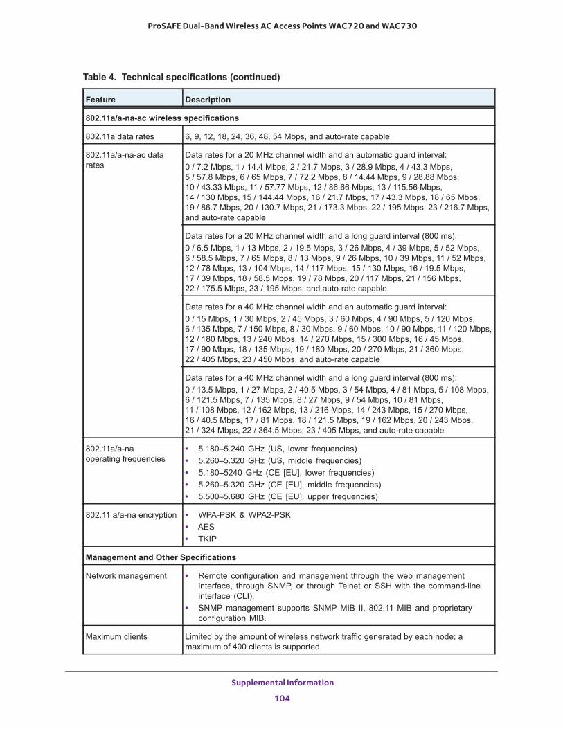
ProSAFE Dual-Band Wireless AC Access Points WAC720 and WAC730
802.11a/a-na-ac wireless specifications
802.11a data rates 6, 9, 12, 18, 24, 36, 48, 54 Mbps, and auto-rate capable
802.11a/a-na-ac data rates
Data rates for a 20 MHz channel width and an automatic guard interval: 0 / 7.2 Mbps, 1 / 14.4 Mbps, 2 / 21.7 Mbps, 3 / 28.9 Mbps, 4 / 43.3 Mbps,5 / 57.8 Mbps, 6 / 65 Mbps, 7 / 72.2 Mbps, 8 / 14.44 Mbps, 9 / 28.88 Mbps,10 / 43.33 Mbps, 11 / 57.77 Mbps, 12 / 86.66 Mbps, 13 / 115.56 Mbps,14 / 130 Mbps, 15 / 144.44 Mbps, 16 / 21.7 Mbps, 17 / 43.3 Mbps, 18 / 65 Mbps,19 / 86.7 Mbps, 20 / 130.7 Mbps, 21 / 173.3 Mbps, 22 / 195 Mbps, 23 / 216.7 Mbps, and auto-rate capable
Data rates for a 20 MHz channel width and a long guard interval (800 ms): 0 / 6.5 Mbps, 1 / 13 Mbps, 2 / 19.5 Mbps, 3 / 26 Mbps, 4 / 39 Mbps, 5 / 52 Mbps, 6 / 58.5 Mbps, 7 / 65 Mbps, 8 / 13 Mbps, 9 / 26 Mbps, 10 / 39 Mbps, 11 / 52 Mbps,12 / 78 Mbps, 13 / 104 Mbps, 14 / 117 Mbps, 15 / 130 Mbps, 16 / 19.5 Mbps, 17 / 39 Mbps, 18 / 58.5 Mbps, 19 / 78 Mbps, 20 / 117 Mbps, 21 / 156 Mbps,22 / 175.5 Mbps, 23 / 195 Mbps, and auto-rate capable
Data rates for a 40 MHz channel width and an automatic guard interval: 0 / 15 Mbps, 1 / 30 Mbps, 2 / 45 Mbps, 3 / 60 Mbps, 4 / 90 Mbps, 5 / 120 Mbps,6 / 135 Mbps, 7 / 150 Mbps, 8 / 30 Mbps, 9 / 60 Mbps, 10 / 90 Mbps, 11 / 120 Mbps,12 / 180 Mbps, 13 / 240 Mbps, 14 / 270 Mbps, 15 / 300 Mbps, 16 / 45 Mbps,17 / 90 Mbps, 18 / 135 Mbps, 19 / 180 Mbps, 20 / 270 Mbps, 21 / 360 Mbps,22 / 405 Mbps, 23 / 450 Mbps, and auto-rate capable
Data rates for a 40 MHz channel width and a long guard interval (800 ms): 0 / 13.5 Mbps, 1 / 27 Mbps, 2 / 40.5 Mbps, 3 / 54 Mbps, 4 / 81 Mbps, 5 / 108 Mbps,6 / 121.5 Mbps, 7 / 135 Mbps, 8 / 27 Mbps, 9 / 54 Mbps, 10 / 81 Mbps, 11 / 108 Mbps, 12 / 162 Mbps, 13 / 216 Mbps, 14 / 243 Mbps, 15 / 270 Mbps,16 / 40.5 Mbps, 17 / 81 Mbps, 18 / 121.5 Mbps, 19 / 162 Mbps, 20 / 243 Mbps,21 / 324 Mbps, 22 / 364.5 Mbps, 23 / 405 Mbps, and auto-rate capable
802.11a/a-naoperating frequencies
• 5.180–5.240 GHz (US, lower frequencies)• 5.260–5.320 GHz (US, middle frequencies)• 5.180–5240 GHz (CE [EU], lower frequencies)• 5.260–5.320 GHz (CE [EU], middle frequencies)• 5.500–5.680 GHz (CE [EU], upper frequencies)
802.11 a/a-na encryption • WPA-PSK & WPA2-PSK• AES• TKIP
Management and Other Specifications
Network management • Remote configuration and management through the web management interface, through SNMP, or through Telnet or SSH with the command-line interface (CLI).
• SNMP management supports SNMP MIB II, 802.11 MIB and proprietary configuration MIB.
Maximum clients Limited by the amount of wireless network traffic generated by each node; a maximum of 400 clients is supported.
Table 4. Technical specifications (continued)
Feature Description
Supplemental Information
104
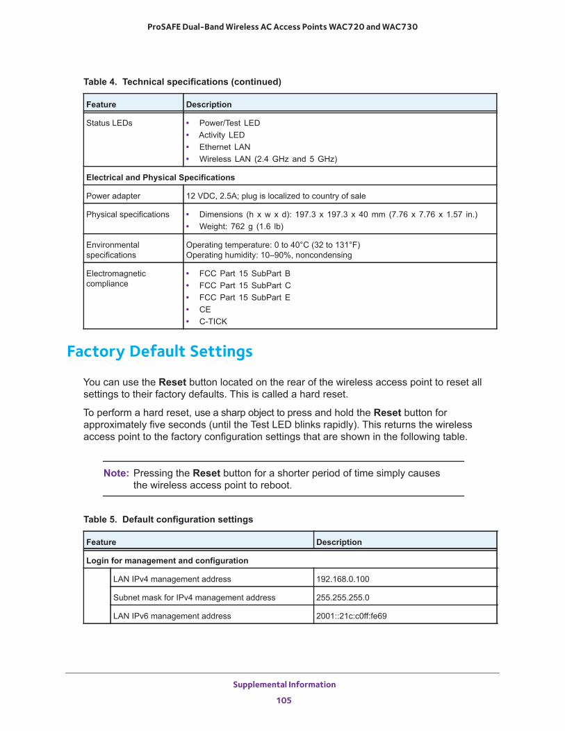
ProSAFE Dual-Band Wireless AC Access Points WAC720 and WAC730
Factory Default Settings
You can use the Reset button located on the rear of the wireless access point to reset all settings to their factory defaults. This is called a hard reset.
To perform a hard reset, use a sharp object to press and hold the Reset button for approximately five seconds (until the Test LED blinks rapidly). This returns the wireless access point to the factory configuration settings that are shown in the following table.
Note: Pressing the Reset button for a shorter period of time simply causes the wireless access point to reboot.
Status LEDs • Power/Test LED• Activity LED• Ethernet LAN• Wireless LAN (2.4 GHz and 5 GHz)
Electrical and Physical Specifications
Power adapter 12 VDC, 2.5A; plug is localized to country of sale
Physical specifications • Dimensions (h x w x d): 197.3 x 197.3 x 40 mm (7.76 x 7.76 x 1.57 in.)• Weight: 762 g (1.6 lb)
Environmental specifications
Operating temperature: 0 to 40°C (32 to 131°F)Operating humidity: 10–90%, noncondensing
Electromagnetic compliance
• FCC Part 15 SubPart B• FCC Part 15 SubPart C• FCC Part 15 SubPart E• CE• C-TICK
Table 5. Default configuration settings
Feature Description
Login for management and configuration
LAN IPv4 management address 192.168.0.100
Subnet mask for IPv4 management address 255.255.255.0
LAN IPv6 management address 2001::21c:c0ff:fe69
Table 4. Technical specifications (continued)
Feature Description
Supplemental Information
105
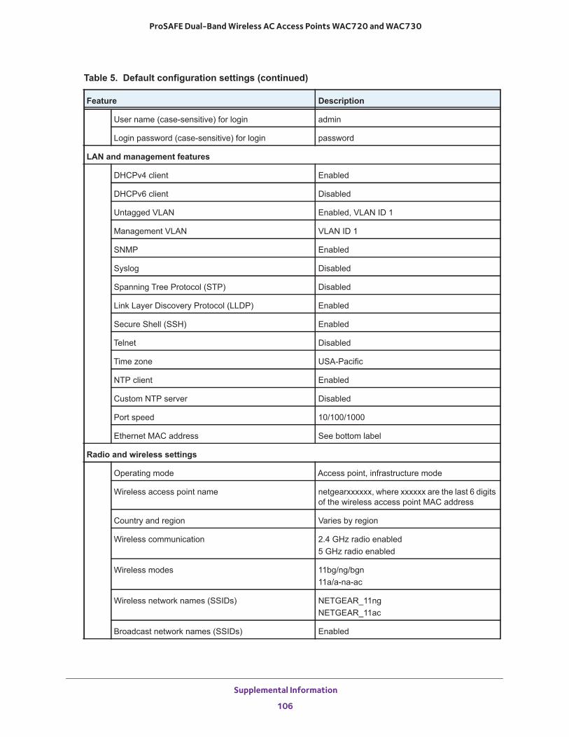
ProSAFE Dual-Band Wireless AC Access Points WAC720 and WAC730
User name (case-sensitive) for login admin
Login password (case-sensitive) for login password
LAN and management features
DHCPv4 client Enabled
DHCPv6 client Disabled
Untagged VLAN Enabled, VLAN ID 1
Management VLAN VLAN ID 1
SNMP Enabled
Syslog Disabled
Spanning Tree Protocol (STP) Disabled
Link Layer Discovery Protocol (LLDP) Enabled
Secure Shell (SSH) Enabled
Telnet Disabled
Time zone USA-Pacific
NTP client Enabled
Custom NTP server Disabled
Port speed 10/100/1000
Ethernet MAC address See bottom label
Radio and wireless settings
Operating mode Access point, infrastructure mode
Wireless access point name netgearxxxxxx, where xxxxxx are the last 6 digits of the wireless access point MAC address
Country and region Varies by region
Wireless communication 2.4 GHz radio enabled5 GHz radio enabled
Wireless modes 11bg/ng/bgn11a/a-na-ac
Wireless network names (SSIDs) NETGEAR_11ngNETGEAR_11ac
Broadcast network names (SSIDs) Enabled
Table 5. Default configuration settings (continued)
Feature Description
Supplemental Information
106
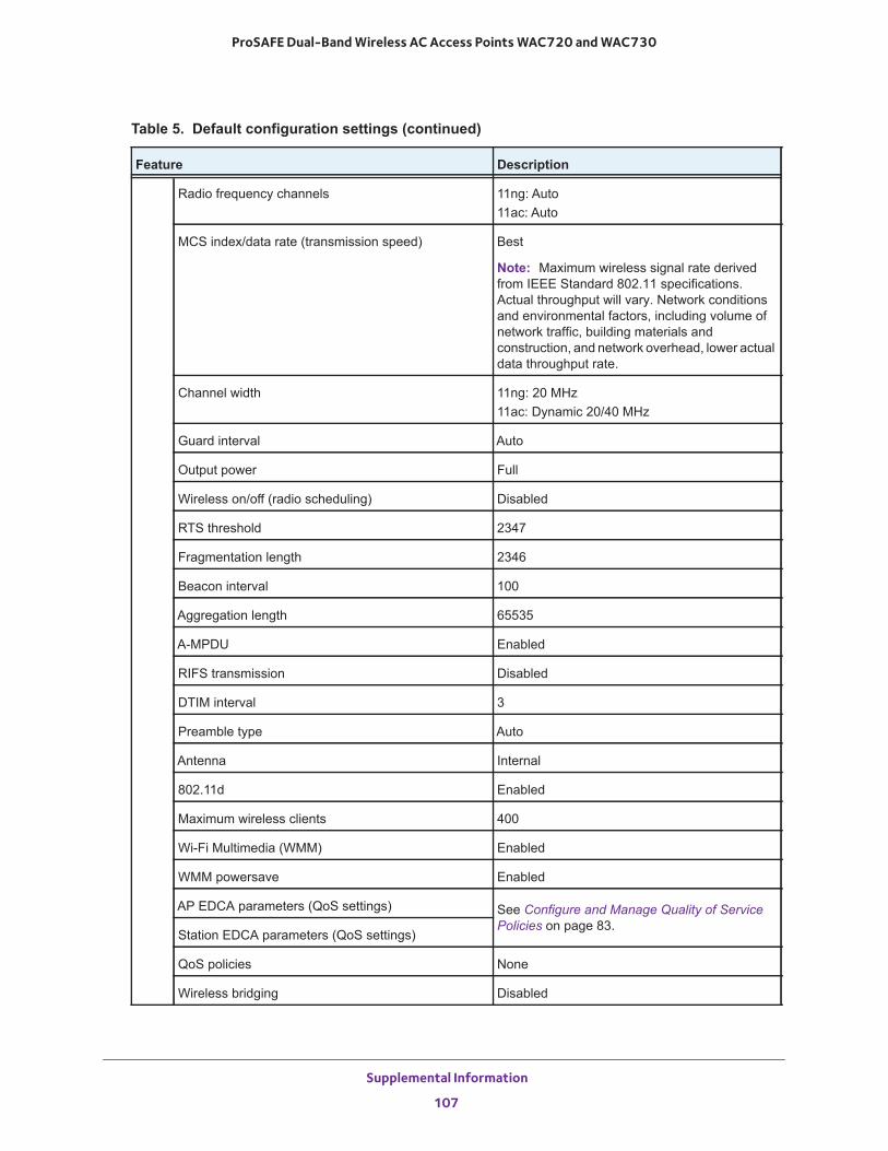
ProSAFE Dual-Band Wireless AC Access Points WAC720 and WAC730
Radio frequency channels 11ng: Auto11ac: Auto
MCS index/data rate (transmission speed) Best
Note: Maximum wireless signal rate derived from IEEE Standard 802.11 specifications. Actual throughput will vary. Network conditions and environmental factors, including volume of network traffic, building materials and construction, and network overhead, lower actual data throughput rate.
Channel width 11ng: 20 MHz11ac: Dynamic 20/40 MHz
Guard interval Auto
Output power Full
Wireless on/off (radio scheduling) Disabled
RTS threshold 2347
Fragmentation length 2346
Beacon interval 100
Aggregation length 65535
A-MPDU Enabled
RIFS transmission Disabled
DTIM interval 3
Preamble type Auto
Antenna Internal
802.11d Enabled
Maximum wireless clients 400
Wi-Fi Multimedia (WMM) Enabled
WMM powersave Enabled
AP EDCA parameters (QoS settings) See Configure and Manage Quality of Service Policies on page 83.
Station EDCA parameters (QoS settings)
QoS policies None
Wireless bridging Disabled
Table 5. Default configuration settings (continued)
Feature Description
Supplemental Information
107
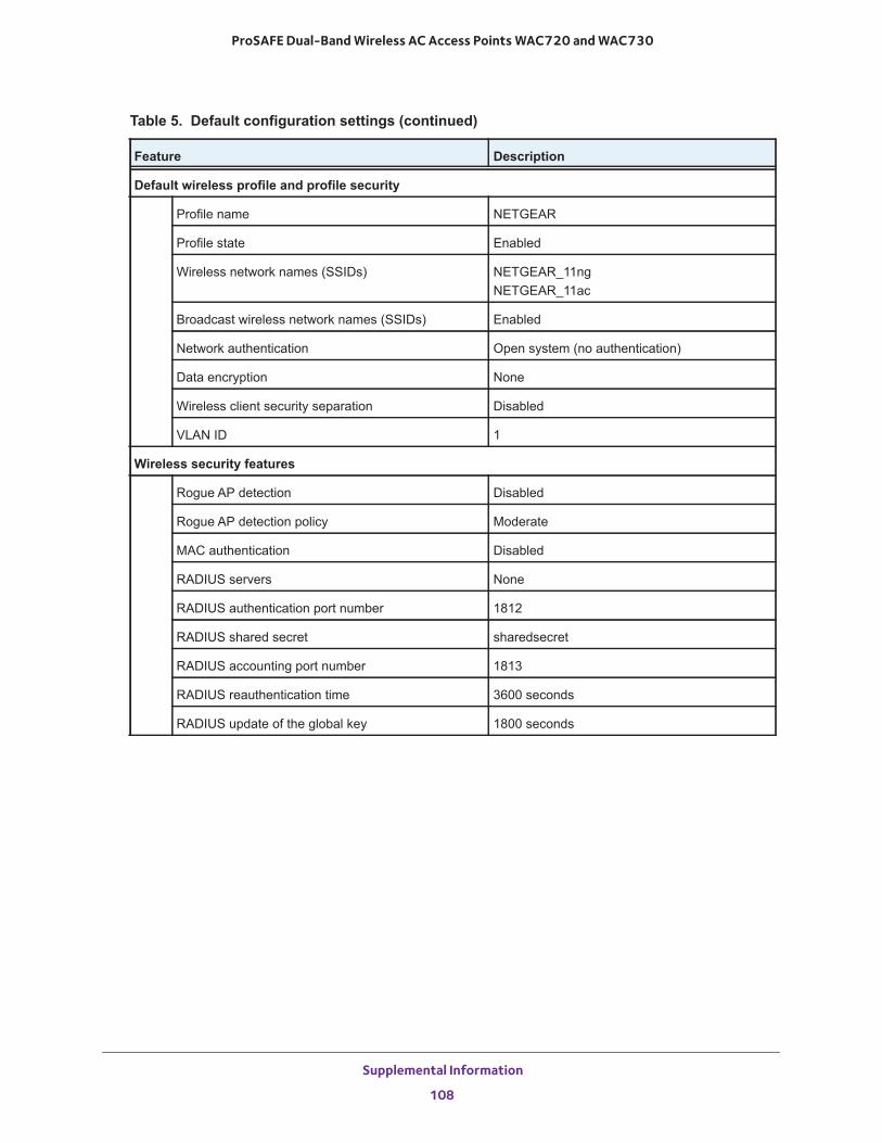
ProSAFE Dual-Band Wireless AC Access Points WAC720 and WAC730
Default wireless profile and profile security
Profile name NETGEAR
Profile state Enabled
Wireless network names (SSIDs) NETGEAR_11ngNETGEAR_11ac
Broadcast wireless network names (SSIDs) Enabled
Network authentication Open system (no authentication)
Data encryption None
Wireless client security separation Disabled
VLAN ID 1
Wireless security features
Rogue AP detection Disabled
Rogue AP detection policy Moderate
MAC authentication Disabled
RADIUS servers None
RADIUS authentication port number 1812
RADIUS shared secret sharedsecret
RADIUS accounting port number 1813
RADIUS reauthentication time 3600 seconds
RADIUS update of the global key 1800 seconds
Table 5. Default configuration settings (continued)
Feature Description
Supplemental Information
108


![Prosafe SE (PRS) · 6020 EmployeesWebsite Cyprus Exchange PRS [Oslo Stock Exchange] Industry Company Overview Prosafe SE (Prosafe) is a provider of semi-submersible accommodation](https://img.pdfslide.net/doc/110x75/6015be59df313a7c091a033d/prosafe-se-prs-6020-employeeswebsite-cyprus-exchange-prs-oslo-stock-exchange.jpg)