Embed Size (px)
Citation preview
69 KOBELCO TECHNOLOGY REVIEW NO. 29 DEC. 2010
Prospects for Coal-based Direct Reduction ProcessHaruyasu MICHISHITA*1, Hidetoshi TANAKA*2*1 Technology & Process Engineering Department, Iron Unit Division, Natural Resources & Engineering Business*2 Research & Development Department, Iron Unit Division, Natural Resources & Engineering Business
Kobe Steel has developed coal-based direct reduction (DR) technologies, the FASTMET, FASTMELT and ITmk3 processes, which reduce carbon composite agglomerates (pellets or briquettes) on the hearth of a rotary hearth furnace (RHF). This paper outlines the features of each process, status of technical development and commercialization. Also described is the contribution of these technologies to environmental compatibility and the security of raw materials, which are becoming critical issues for the steel industry worldwide.
Introduction
Unlike blast furnaces, direct reduction ironmaking
plants using natural gas (e.g., the MIDREX� process
and HYL process) have the characteristics of
requiring a smaller capital expenditure and no
coking coal. Many direct reduction plants have been
built in developing contries, particularly those that
produce natural gas. In recent years, there has been
an increased demand for direct reduced iron
(hereinafter referred to as "DRI") as an alternative to
high quality scrap. Electric arc furnace (EAF) mills
are dominant in the steel industry in advanced
countries, which is boosting the demand for DRI.
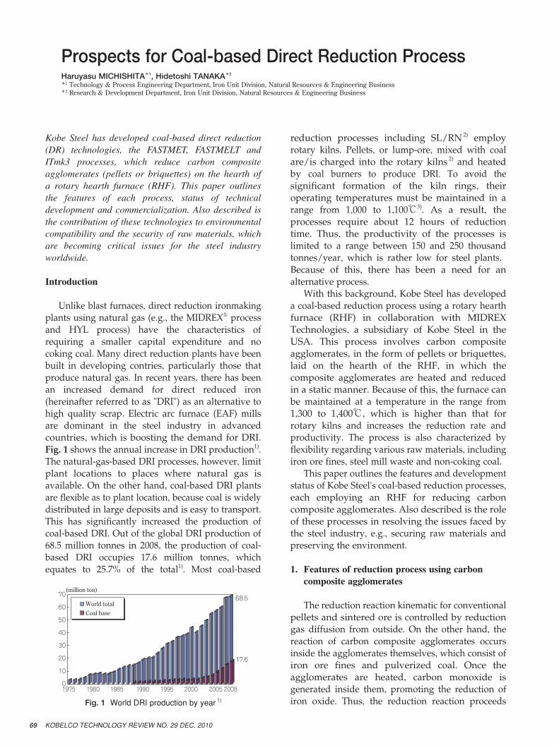
Fig. 1 shows the annual increase in DRI production1).
The natural-gas-based DRI processes, however, limit
plant locations to places where natural gas is
available. On the other hand, coal-based DRI plants
are flexible as to plant location, because coal is widely
distributed in large deposits and is easy to transport.
This has significantly increased the production of
coal-based DRI. Out of the global DRI production of
68.5 million tonnes in 2008, the production of coal-
based DRI occupies 17.6 million tonnes, which
equates to 25.7% of the total1). Most coal-based
reduction processes including SL/RN 2) employ
rotary kilns. Pellets, or lump-ore, mixed with coal
are/is charged into the rotary kilns 2) and heated
by coal burners to produce DRI. To avoid the
significant formation of the kiln rings, their
operating temperatures must be maintained in a
range from 1,000 to 1,100℃3). As a result, the
processes require about 12 hours of reduction
time. Thus, the productivity of the processes is
limited to a range between 150 and 250 thousand
tonnes/year, which is rather low for steel plants.
Because of this, there has been a need for an
alternative process.
With this background, Kobe Steel has developed
a coal-based reduction process using a rotary hearth
furnace (RHF) in collaboration with MIDREX
Technologies, a subsidiary of Kobe Steel in the
USA. This process involves carbon composite
agglomerates, in the form of pellets or briquettes,
laid on the hearth of the RHF, in which the
composite agglomerates are heated and reduced
in a static manner. Because of this, the furnace can
be maintained at a temperature in the range from
1,300 to 1,400℃, which is higher than that for
rotary kilns and increases the reduction rate and
productivity. The process is also characterized by
flexibility regarding various raw materials, including
iron ore fines, steel mill waste and non-coking coal.
This paper outlines the features and development
status of Kobe Steel's coal-based reduction processes,
each employing an RHF for reducing carbon
composite agglomerates. Also described is the role
of these processes in resolving the issues faced by
the steel industry, e.g., securing raw materials and
preserving the environment.
1. Features of reduction process using carbon composite agglomerates
The reduction reaction kinematic for conventional
pellets and sintered ore is controlled by reduction
gas diffusion from outside. On the other hand, the
reaction of carbon composite agglomerates occurs
inside the agglomerates themselves, which consist of
iron ore fines and pulverized coal. Once the
agglomerates are heated, carbon monoxide is
generated inside them, promoting the reduction of
iron oxide. Thus, the reduction reaction proceeds
1975 1980 1985 1990 1995 2000 2005
World totalCoal base
2008
(million ton)
17.6
68.570�
60�
50�
40�
30�
20�
10�
0
Fig. 1 World DRI production by year 1)
70KOBELCO TECHNOLOGY REVIEW NO. 29 DEC. 2010
faster in the carbon composite agglomerates than in
conventional pellets and sintered ore, whose reaction
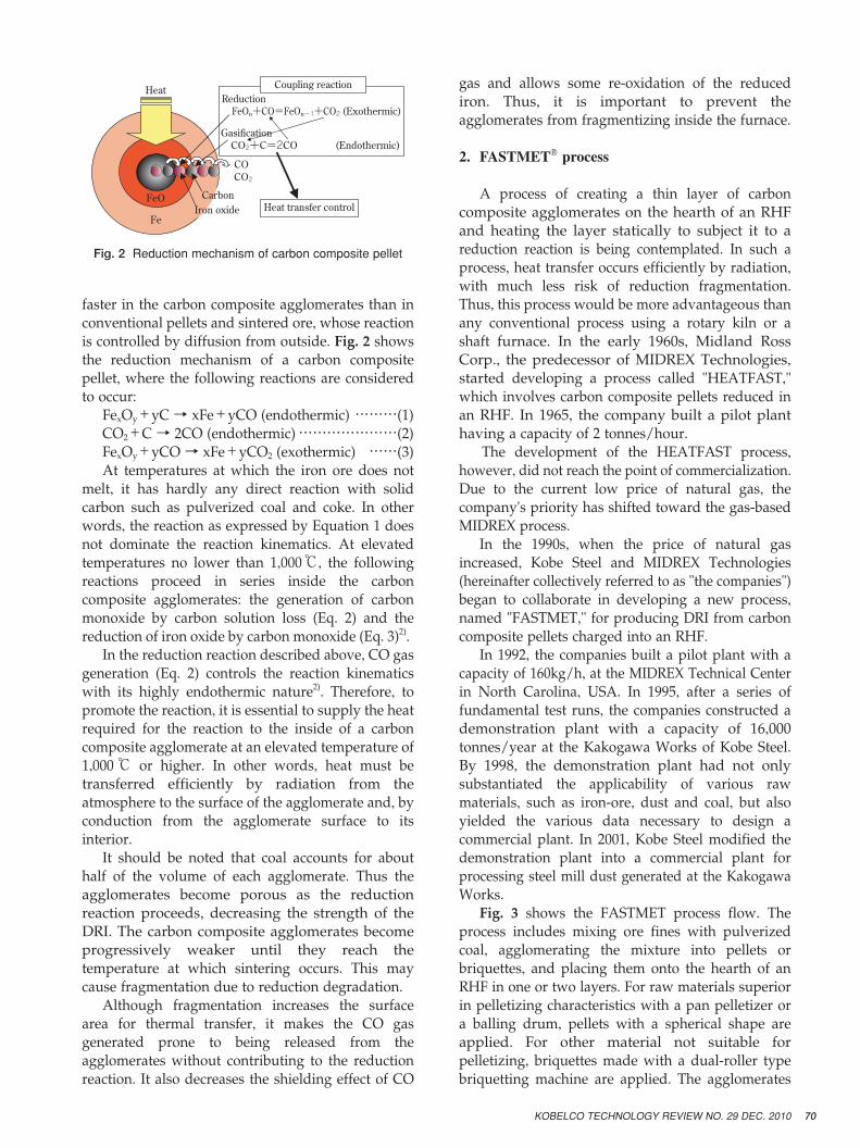
is controlled by diffusion from outside. Fig. 2 shows
the reduction mechanism of a carbon composite
pellet, where the following reactions are considered
to occur:
FexOy+yC → xFe+yCO (endothermic) ………(1)
CO2+C → 2CO (endothermic) …………………(2)
FexOy+yCO → xFe+yCO2 (exothermic) ……(3)
At temperatures at which the iron ore does not
melt, it has hardly any direct reaction with solid
carbon such as pulverized coal and coke. In other
words, the reaction as expressed by Equation 1 does
not dominate the reaction kinematics. At elevated
temperatures no lower than 1,000℃, the following
reactions proceed in series inside the carbon
composite agglomerates: the generation of carbon
monoxide by carbon solution loss (Eq. 2) and the
reduction of iron oxide by carbon monoxide (Eq. 3)2).
In the reduction reaction described above, CO gas
generation (Eq. 2) controls the reaction kinematics
with its highly endothermic nature2). Therefore, to
promote the reaction, it is essential to supply the heat
required for the reaction to the inside of a carbon
composite agglomerate at an elevated temperature of
1,000℃ or higher. In other words, heat must be
transferred efficiently by radiation from the
atmosphere to the surface of the agglomerate and, by
conduction from the agglomerate surface to its
interior.
It should be noted that coal accounts for about
half of the volume of each agglomerate. Thus the
agglomerates become porous as the reduction
reaction proceeds, decreasing the strength of the
DRI. The carbon composite agglomerates become
progressively weaker until they reach the
temperature at which sintering occurs. This may
cause fragmentation due to reduction degradation.
Although fragmentation increases the surface
area for thermal transfer, it makes the CO gas
generated prone to being released from the
agglomerates without contributing to the reduction
reaction. It also decreases the shielding effect of CO
gas and allows some re-oxidation of the reduced
iron. Thus, it is important to prevent the
agglomerates from fragmentizing inside the furnace.
2. FASTMET� process
A process of creating a thin layer of carbon
composite agglomerates on the hearth of an RHF
and heating the layer statically to subject it to a
reduction reaction is being contemplated. In such a
process, heat transfer occurs efficiently by radiation,
with much less risk of reduction fragmentation.
Thus, this process would be more advantageous than
any conventional process using a rotary kiln or a
shaft furnace. In the early 1960s, Midland Ross
Corp., the predecessor of MIDREX Technologies,
started developing a process called "HEATFAST,"
which involves carbon composite pellets reduced in
an RHF. In 1965, the company built a pilot plant
having a capacity of 2 tonnes/hour.
The development of the HEATFAST process,
however, did not reach the point of commercialization.
Due to the current low price of natural gas, the
company's priority has shifted toward the gas-based
MIDREX process.
In the 1990s, when the price of natural gas
increased, Kobe Steel and MIDREX Technologies
(hereinafter collectively referred to as "the companies")
began to collaborate in developing a new process,
named "FASTMET," for producing DRI from carbon
composite pellets charged into an RHF.
In 1992, the companies built a pilot plant with a
capacity of 160kg/h, at the MIDREX Technical Center
in North Carolina, USA. In 1995, after a series of
fundamental test runs, the companies constructed a
demonstration plant with a capacity of 16,000
tonnes/year at the Kakogawa Works of Kobe Steel.
By 1998, the demonstration plant had not only
substantiated the applicability of various raw
materials, such as iron-ore, dust and coal, but also
yielded the various data necessary to design a
commercial plant. In 2001, Kobe Steel modified the
demonstration plant into a commercial plant for
processing steel mill dust generated at the Kakogawa
Works.
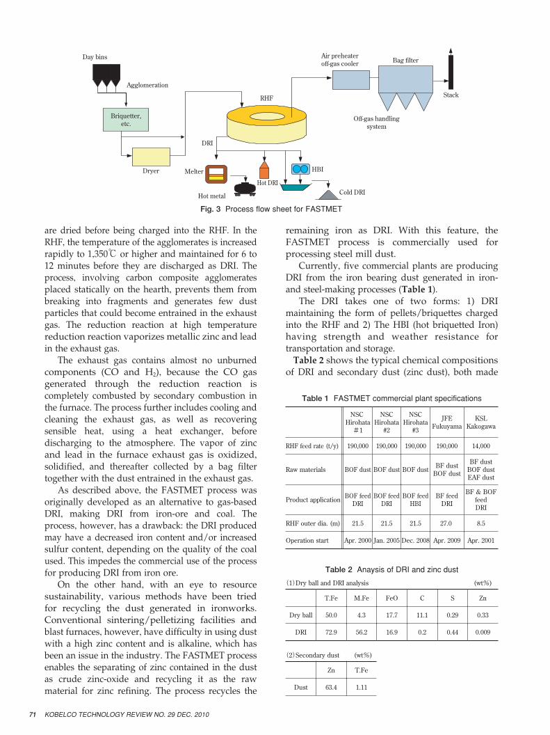
Fig. 3 shows the FASTMET process flow. The
process includes mixing ore fines with pulverized
coal, agglomerating the mixture into pellets or
briquettes, and placing them onto the hearth of an
RHF in one or two layers. For raw materials superior
in pelletizing characteristics with a pan pelletizer or
a balling drum, pellets with a spherical shape are
applied. For other material not suitable for
pelletizing, briquettes made with a dual-roller type
briquetting machine are applied. The agglomerates
�
Iron oxideCarbon
Heat transfer controlFeO
Fe
CO
Coupling reactionHeatReduction� FeOn+CO=FeOn-1+CO2 (Exothermic)
Gasification� CO2+C=2CO (Endothermic)
CO2
Fig. 2 Reduction mechanism of carbon composite pellet
71 KOBELCO TECHNOLOGY REVIEW NO. 29 DEC. 2010
are dried before being charged into the RHF. In the
RHF, the temperature of the agglomerates is increased
rapidly to 1,350℃ or higher and maintained for 6 to
12 minutes before they are discharged as DRI. The
process, involving carbon composite agglomerates
placed statically on the hearth, prevents them from
breaking into fragments and generates few dust
particles that could become entrained in the exhaust
gas. The reduction reaction at high temperature
reduction reaction vaporizes metallic zinc and lead
in the exhaust gas.
The exhaust gas contains almost no unburned
components (CO and H2), because the CO gas
generated through the reduction reaction is
completely combusted by secondary combustion in
the furnace. The process further includes cooling and
cleaning the exhaust gas, as well as recovering
sensible heat, using a heat exchanger, before
discharging to the atmosphere. The vapor of zinc
and lead in the furnace exhaust gas is oxidized,
solidified, and thereafter collected by a bag filter
together with the dust entrained in the exhaust gas.
As described above, the FASTMET process was
originally developed as an alternative to gas-based
DRI, making DRI from iron-ore and coal. The
process, however, has a drawback: the DRI produced
may have a decreased iron content and/or increased
sulfur content, depending on the quality of the coal
used. This impedes the commercial use of the process
for producing DRI from iron ore.
On the other hand, with an eye to resource
sustainability, various methods have been tried
for recycling the dust generated in ironworks.
Conventional sintering/pelletizing facilities and
blast furnaces, however, have difficulty in using dust
with a high zinc content and is alkaline, which has
been an issue in the industry. The FASTMET process
enables the separating of zinc contained in the dust
as crude zinc-oxide and recycling it as the raw
material for zinc refining. The process recycles the
remaining iron as DRI. With this feature, the
FASTMET process is commercially used for
processing steel mill dust.
Currently, five commercial plants are producing
DRI from the iron bearing dust generated in iron-
and steel-making processes (Table 1).
The DRI takes one of two forms: 1) DRI
maintaining the form of pellets/briquettes charged
into the RHF and 2) The HBI (hot briquetted Iron)
having strength and weather resistance for
transportation and storage.
Table 2 shows the typical chemical compositions
of DRI and secondary dust (zinc dust), both made
KSLKakogawa
JFEFukuyama
NSCHirohata#3
NSCHirohata#2
NSC Hirohata#1
14,000190,000190,000190,000190,000RHF feed rate (t/y)
BF dustBOF dustEAF dust
BF dustBOF dustBOF dustBOF dustBOF dustRaw materials
BF & BOFfeedDRI
BF feedDRI
BOF feedHBI
BOF feedDRI
BOF feedDRIProduct application
8.527.0 21.521.521.5RHF outer dia. (m)
Apr. 2001Apr. 2009Dec. 2008Jan. 2005Apr. 2000Operation start
(wt%)(1)Dry ball and DRI analysis
ZnSCFeOM.FeT.Fe
0.330.2911.117.74.350.0Dry ball
0.0090.440.216.956.272.9DRI
(2)Secondary dust (wt%)
T.FeZn
1.1163.4Dust
Table 1 FASTMET commercial plant specifications
Table 2 Anaysis of DRI and zinc dust
Day bins
Agglomeration
Briquetter,�etc.
Dryer Melter
Hot metal
DRI
RHF
Air preheater�off-gas cooler Bag filter
Stack
Off-gas handling�system
Hot DRICold DRI
HBI
Fig. 3 Process flow sheet for FASTMET
72KOBELCO TECHNOLOGY REVIEW NO. 29 DEC. 2010
from steel mill waste by the FASTMET process5). The
FASTMET process produces DRI at a high reduction
ratio and crude zinc oxide of high purity, as it gives
rise to little entrained metal dust. This characteristic
of the process contributes to the recycling of iron and
zinc from steel mill waste.
3. FASTMELT� process
As previously mentioned, the higher gangue and
sulfur content derived from the coal is an issue with
DRI produced by the FASTMET process. To resolve
this issue, the companies developed a process called
"FASTMELT." The process includes producing DRI
using an RHF (the FASTMET process), transferring
the DRI at a high (as-discharged) temperature to a
furnace, melting the DRI in the furnace, and
removing sulfur and separating slag to produce
molten iron6), 7). The melting furnace can be either an
electric arc furnace6) or a coal-based melter7) using the
thermal energy of coal and oxygen that are supplied.
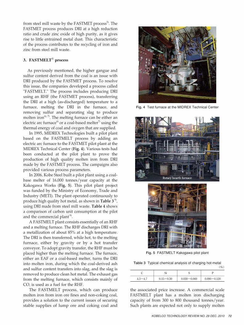
In 1995, MIDREX Technologies built a pilot plant
based on the FASTMELT process by adding an
electric arc furnace to the FASTMET pilot plant at the
MIDREX Technical Center (Fig. 4). Various tests had
been conducted at the pilot plant to prove the
production of high quality molten iron from DRI
made by the FASTMET process. The campaigns also
provided various process parameters.
In 2006, Kobe Steel built a pilot plant using a coal-
base melter of 16,000 tonnes/year capacity at the
Kakogawa Works (Fig. 5). This pilot plant project
was funded by the Ministry of Economy, Trade and
Industry (METI). The plant operated continuously to
produce high quality hot metal, as shown in Table 3 9),
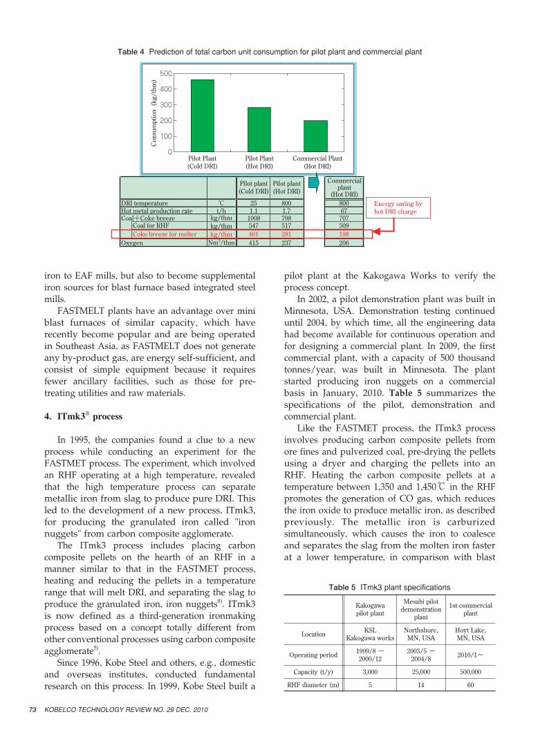
using DRI made from steel mill waste. Table 4 shows
a comparison of carbon unit consumption at the pilot
and the commercial plant 9).
A FASTMELT plant consists essentially of an RHF
and a melting furnace. The RHF discharges DRI with
a metallization of about 85% at a high temperature.
The DRI is then transferred, while hot, to the melting
furnace, either by gravity or by a hot transfer
conveyor. To adopt gravity transfer, the RHF must be
placed higher than the melting furnace. The furnace,
either an EAF or a coal-based melter, turns the DRI
into molten iron, during which the coal-derived ash
and sulfur content transfers into slag, and the slag is
removed to produce clean hot metal. The exhaust gas
from the melting furnace, which consists mainly of
CO, is used as a fuel for the RHF.
The FASTMELT process, which can produce
molten iron from iron ore fines and non-coking coal,
provides a solution to the current issues of securing
stable supplies of lump ore and coking coal and
the associated price increase. A commercial scale
FASTMELT plant has a molten iron discharging
capacity of from 300 to 800 thousand tonnes/year.
Such plants are expected not only to supply molten
Fig. 4 Test furnace at the MIDREX Technical Center
Rotary hearth furnace�
Coal based DRI melter�
(%)
PSSiC
0.090~0.1200.030~0.0600.15~0.304.3~4.7
Fig. 5 FASTMELT Kakogawa pilot plant
Table 3 Typical chemical analysis of charging hot-metal
73 KOBELCO TECHNOLOGY REVIEW NO. 29 DEC. 2010
iron to EAF mills, but also to become supplemental
iron sources for blast furnace based integrated steel
mills.
FASTMELT plants have an advantage over mini
blast furnaces of similar capacity, which have
recently become popular and are being operated
in Southeast Asia, as FASTMELT does not generate
any by-product gas, are energy self-sufficient, and
consist of simple equipment because it requires
fewer ancillary facilities, such as those for pre-
treating utilities and raw materials.
4. ITmk3� process
In 1995, the companies found a clue to a new
process while conducting an experiment for the
FASTMET process. The experiment, which involved
an RHF operating at a high temperature, revealed
that the high temperature process can separate
metallic iron from slag to produce pure DRI. This
led to the development of a new process, ITmk3,
for producing the granulated iron called "iron
nuggets" from carbon composite agglomerate.
The ITmk3 process includes placing carbon
composite pellets on the hearth of an RHF in a
manner similar to that in the FASTMET process,
heating and reducing the pellets in a temperature
range that will melt DRI, and separating the slag to
produce the granulated iron, iron nuggets8). ITmk3
is now defined as a third-generation ironmaking
process based on a concept totally different from
other conventional processes using carbon composite
agglomerate5).
Since 1996, Kobe Steel and others, e.g., domestic
and overseas institutes, conducted fundamental
research on this process. In 1999, Kobe Steel built a
pilot plant at the Kakogawa Works to verify the
process concept.
In 2002, a pilot demonstration plant was built in
Minnesota, USA. Demonstration testing continued
until 2004, by which time, all the engineering data
had become available for continuous operation and
for designing a commercial plant. In 2009, the first
commercial plant, with a capacity of 500 thousand
tonnes/year, was built in Minnesota. The plant
started producing iron nuggets on a commercial
basis in January, 2010. Table 5 summarizes the
specifications of the pilot, demonstration and
commercial plant.
Like the FASTMET process, the ITmk3 process
involves producing carbon composite pellets from
ore fines and pulverized coal, pre-drying the pellets
using a dryer and charging the pellets into an
RHF. Heating the carbon composite pellets at a
temperature between 1,350 and 1,450℃ in the RHF
promotes the generation of CO gas, which reduces
the iron oxide to produce metallic iron, as described
previously. The metallic iron is carburized
simultaneously, which causes the iron to coalesce
and separates the slag from the molten iron faster
at a lower temperature, in comparison with blast
DRI temperature 25 800Hot metal production rate 1.1 1.7Coal+Coke breeze 1008 798Coal for RHF 547 517Coke breeze for melter 461 281
237415Oxygen
80067707509198206
500�
400�
300�
200�
100�
0Consumption (kg/thm)
Pilot Plant�(Cold DRI)
Pilot Plant�(Hot DRI)
Commercial Plant�(Hot DRI)
Energy saving by�hot DRI charge
Pilot plant�(Cold DRI)
Pilot plant�(Hot DRI)
Commercial�plant�
(Hot DRI)℃�t/h�kg/thm�kg/thm�kg/thm�Nm3/thm
Table 4 Prediction of total carbon unit consumption for pilot plant and commercial plant
1st commercialplant
Mesabi pilotdemonstration
plant
Kakogawapilot plant
Hoyt Lake,MN, USA
Northshore,MN, USA
KSLKakogawa worksLocation
2010/1~2003/5 ~2004/8
1999/8 ~2000/12Operating period
500,00025,0003,000Capacity (t/y)
60145RHF diameter (m)
Table 5 ITmk3 plant specifications
74KOBELCO TECHNOLOGY REVIEW NO. 29 DEC. 2010
furnaces, as explained by the phase diagram in
Fig. 6 4). After cooling, the solid nuggets and slag are
discharged out of the RHF. This series of reactions is
completed within 8 to 10 minutes, during which
time, the iron is distinctly separated from the slag4).
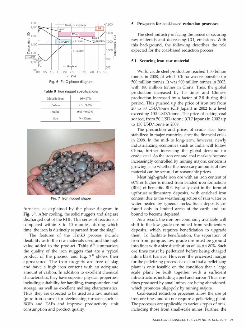
The features of the ITmk3 process include
flexibility as to the raw materials used and the high
value added to the product. Table 6 4) summarizes
the quality of the iron nuggets that are a typical
product of the process, and Fig. 7 4) shows their
appearance. The iron nuggets are free of slag
and have a high iron content with an adequate
amount of carbon. In addition to excellent chemical
characteristics, they have superior physical properties,
including suitability for handling, transportation and
storage, as well as excellent melting characteristics.
Thus, they are expected to be used as a raw material
(pure iron source) for steelmaking furnaces such as
BOFs and EAFs and improve productivity, unit
consumption and product quality.
5. Prospects for coal-based reduction processes
The steel industry is facing the issues of securing
raw materials and decreasing CO2 emissions. With
this background, the following describes the role
expected for the coal-based reduction process.
5.1 Securing iron raw material
World crude steel production reached 1.33 billion
tonnes in 2008, of which China was responsible for
500 million tonnes. It was 900 million tonnes in 2002,
with 180 million tonnes in China. Thus, the global
production increased by 1.5 times and Chinese
production increased by a factor of 2.8 during this
period. This pushed up the price of iron ore from
20 to 30 USD/tonne (CIF Japan) in 2002 to a level
exceeding 100 USD/tonne. The price of coking coal
soared, from 50 USD/tonne (CIF Japan) in 2002 up
to 130 USD/tonne in 2009.
The production and prices of crude steel have
stabilized in major countries since the financial crisis
in 2008. In the mid- to long-term, however, newly
industrializing economies such as India will follow
China, further increasing the global demand for
crude steel. As the iron ore and coal markets become
increasingly controlled by mining majors, concern is
growing as to whether the necessary amounts of raw
material can be secured at reasonable prices.
Most high-grade iron ore with an iron content of
60% or higher is mined from banded iron formations
(BIFs) of hematite. BIFs typically exist in the form of
upthrust sedimentary deposits, with enriched iron
content due to the weathering action of rain water or
water heated by igneous rocks. Such deposits are
found only in limited areas of the earth and are
bound to become depleted.
As a result, the iron ore commonly available will
shift to the low grade ore mined from sedimentary
deposits, which requires beneficiation to upgrade
them. To facilitate beneficiation, the separation of
iron from gangue, low grade ore must be ground
into fines with a size distribution of -44μ> 80%. Such
ore fines must be pelletized before being charged
into a blast furnace. However, the price-cost margin
for the pelletizing process is so slim that a pelletizing
plant is only feasible on the condition that a large
scale plant be built together with a sufficient
infrastructure, including a port and harbor. Thus, ore-
fines produced by small mines are being abandoned,
which promotes oligopoly by mining majors.
Coal-based reduction processes allow the use of
iron ore fines and do not require a pelletizing plant.
The processes are applicable to various types of ores,
including those from small-scale mines. Further, the
Liquid�+GraphiteFASTMET�
BFLiquid
α+Graphite
α�+� γ�α�
γ+Graphite
γ+Liquid
Stable Fe-C system
γ�
Gas DR�
1,600�
1,400�
1,200�
1,000�
800�
600
C (%)
Temperature (℃)
Temperature (K)
1,900�
1,800�
1,600�
1,400�
1,200�
1,000�
8000.0 0.5 1.0 1.5 2.0 2.5 3.0 3.5 4.0 4.5 5.0
ITmk3
Fig. 6 Fe-C phase diagram
96~97%Metallic Iron
2.5~3.0%Carbon
0.05~0.07%Sulfur
5~25mmSize
Table 6 Iron nugget specifications
Fig. 7 Iron nugget shape
75 KOBELCO TECHNOLOGY REVIEW NO. 29 DEC. 2010
production scale of an ITmk3 plant well fits the
production scale of small mines. Beside the mines,
an ITmk3 plant can be built to produce a valuable
product in the form of iron nuggets. This is a new
business model which allows the use of low grade
ore that was never before utilized. The first
commercial ITmk3 plant, build in Minnesota, USA,
is not an exception. An American EAF maker seeking
for a stable source of iron purchased an abandoned
iron mine where high grade ore had been depleted
and only low grade ore can be mined. The company
produces iron nuggets for its own use, using the low
grade ore at the ITmk3 plant.
Thus, the coal-based reduction process by Kobe
Steel promotes the supply of iron from mines that are
producing low grade ore on a small scale. The
process is expected to prevent an oligopoly by
mining giants and contribute to a stable supply of
iron at a reasonable price.
The possible depletion of coking coal is another
concern. Blast furnaces require high grade coking
coal. The reserve for such coking coal is estimated to
be only 10% of the total coal reserves. Coke ovens
also pose issues of environmental burden, including
CO2 emissions. Decrepit coke ovens, existing mainly
in advanced countries, are difficult to refit or replace,
making the supply of coke to blast furnaces tighter
and tighter. Coal-based reduction that enables the
use of non-coking coal is now drawing attention as
a coke-less ironmaking process.
5.2 CO2 emission reduction by utilizing scrap
At COP15 held in September 2009, the Japanese
government committed to decrease CO2 emissions
by 25% of the 1990 level by 2020. Now the Japanese
iron and steel industry, responsible for approximately
16% of the country's total CO2 emissions, is under
even greater pressure. The ironmaking process, in
particular, is responsible for more than 60% of the
industry's CO2 emissions, which makes it important
to decrease the CO2 emissions from this process.
In the iron & steel making process at a blast
furnace integrated steel works, the largest amount of
energy is consumed in reducing iron ore. The BF
(blast furnace) - BOF (basic oxygen furnace) process
emits approximately two tonnes of CO2 in producing
one tonne of molten steel. On the other hand, an EAF
process emits only a quarter of that amount, or
approximately 0.5 tonnes, of CO2 when it melts scrap
to produce the same amount of molten steel. Thus,
shifting from the BF (blast furnace) - BOF (basic
oxygen furnace) process to the scrap-based EAF
process is an effective approach for reducing CO2
emissions.
The BF (blast furnace) - BOF (basic oxygen furnace)
process has utilized scrap in recent years; however,
there is a limit to the quantity of scrap that can be
used. Blast furnaces can process only a limited
amount of scrap because zinc contained in the scrap
can adhere to the top shell of the furnace. Scrap is
also difficult to handle using the existing equipment
for charging raw materials. A BOF (basic oxygen
furnace) can melt only a limited amount of scrap
without supplemental energy. Further, the impurities
contained in the scrap may impair the product
quality, which also limits the applicable amount. As
a result, the BF (blast furnace) - BOF (basic oxygen
furnace) process can use only up to 10 to 15% of scrap.
On the other hand, the EAF process can
effectively use scrap to decrease CO2 emissions;
however, this process is susceptible to issues of
scrap quality and the fluctuation of scrap prices.
General scrap contains tramp elements, such as Cu
and Sn, which can adversely affect the quality of
downstream processes, including continuous casting
and rolling. These tramp elements are difficult to
remove from molten iron or steel. Thus their content
must be controlled either by choosing clean scrap
free from these elements or by diluting the scrap
with clean iron such as DRI and pig-iron. Despite
the growing trend toward scrap recycling, it is
unlikely that the amount of available clean scrap,
such as machining scrap, will increase significantly.
Securing high quality scrap will become more
difficult.
Thus, as more scrap is used, the demand for clean
iron such as DRI will certainly increase to maintain
the quality and cost of products. On the other hand,
there is concern as to whether the supply of DRI can
meet the growing demand for clean iron. Seventy-
five percent of DRI is currently produced by the
natural gas based direct reduction process, but its
production is limited to locations where natural gas
is available. In addition, the process can use only
high quality pellets specially produced for the
process.
Under such circumstances, coal-based direct
reduction is gaining attention as an alternative
process for producing clean iron such as DRI, which
will fill the supply and demand gap. The process is
expected to promote shifting from the BF (blast
furnace) - BOF (basic oxygen furnace) process to the
scrap-based EAF process and eventually reduce CO2
emissions in the iron and steel industry.
5.3 Processing ironmaking dust
The FASTMET process not only recovers iron
from ironmaking dust, which otherwise would be
76KOBELCO TECHNOLOGY REVIEW NO. 29 DEC. 2010
discarded, but also is effective in reducing CO2
emissions. In ironmaking dust, iron (Fe) exists as a
partially oxidized mixture of Fe and FeO. Using
such dust decreases the reduction energy. In
addition, the carbon contained in the dust is utilized
as a reductant, which decreases the consumption of
coal and coke and, thus, reduces CO2 emissions.
It is anticipated that, even if the amount of scrap
used by the BF (blast furnace) - BOF (basic oxygen
furnace) process remains at the same level, the
quality of scrap will deteriorate as the content of zinc
and alkali increases. Thus, the demand is expected to
grow for the FASTMET process, which separates out
zinc and alkali elements and enables iron recycling in
the form of DRI.
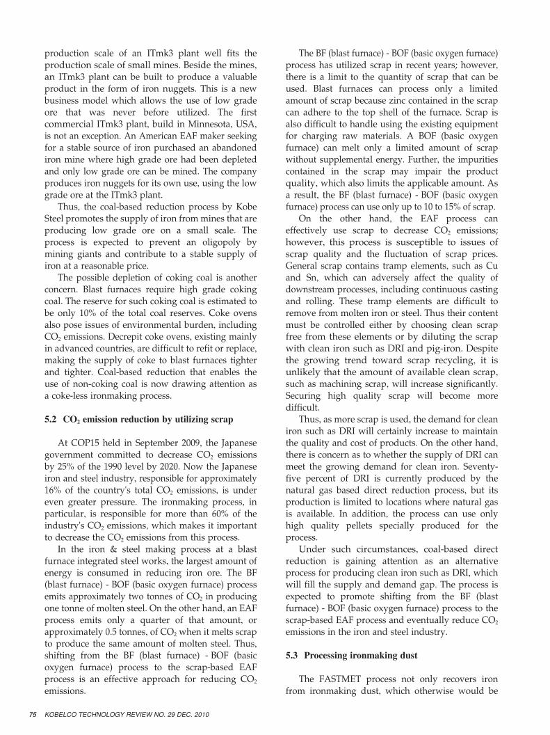
The amount of dust generated from EAFs is
expected to increase as the conversion from BF (blast
furnace) - BOF (basic oxygen furnace) to EAF
proceeds. As shown in Table 7 6), typical EAF dust
has a high content of zinc and salt and a low iron
content. Thus, EAF dust has been mostly disposed
of in landfills.
Under the circumstance, the FASTMET process is
expected to provide a solution to this sort of issue
by treating EAF dust to recover iron and zinc. EAF
dust processing has been demonstrated by the pilot
plant at the Kakogawa Works of Kobe Steel. Now
that the experimental and demonstration stage has
ended, FASTMET is ready to be applied at the
commercial-scale EAF dust processing plant.
5.4 Utilizing green energy
All three of the FASTMET, FASTMELT and
ITmk3 processes involve reductant carbon and
burner fuel. It is technically possible to utilize the
carbon derived from biomass such as wood chips
and to utilize the synthetic fuel gas derived from the
biomass or industrial waste. These processes will
reduce CO2 emissions.
One idea is to recycle municipal solid waste, sewage
sludge and industrial waste as environmentally sound
carbon sources for DRI. Such a system may be
incorporated into the social infrastructure.
Another idea may be to grow biomass in the vast
land surrounding a mining site where an ITmk3
plant is built. The biomass would be used as a
renewable energy source for DRI production.
Conclusions
1) Supplies of high grade iron ore and coking coal
are becoming tight. Securing them is becoming
more and more difficult. Coal-based direct
reduction processes are expected to diversify the
sources of raw materials, since they are coke-less
processes and flexible as to raw materials. This
will stave off an oligopoly by mining giants and
ensure a stable supply of raw materials for the
steel industry.
2) Having a stable supply of clean iron produced by
a coal-based reduction process will make up for
the shortage of high grade scrap, while scrap
quality is expected to deteriorate in future. This
will promote the conversion to the scrap-based
EAF process and eventually decrease CO2
emissions in the steel industry.
3) A DRI production technology developed for
utilizing not only steel mill waste, but also
municipal waste and biomass, will help the steel
industry sustain its activity in harmony with the
environment.
References
1) MIDREX : 2008 World Direct Reduction Statics (2009).
2) W.Schnabel et al. : Ironmaking Conf. Proceeding 42(1983).
3) H. TANAKA : NISHIYAMA Commemorative Lecture (in Japanese), 2008, The Iron and Steel Institute of Japan.
4) T. HARADA et al. : R&D Kobe Steel Engineering Reports,
Vol.55, No.2(2005), pp.128-132.
5) T. HARADA et al. : KOBELCO TECHNOLOGY REVIEW,
No.24 (2001), pp.26-31.
6) Japanese Patent No.3509072.
7) Japanese Patent No.3940366.
8) Japanese Patent No.3845893.
9) H. FUJIMOTO et al. : R&D Kobe Steel Engineering Reports,
Vol.59, No.2(2009), pp.73-79.
(wt%)(1)EAF dust analysis
ClSSiO2CaOCPbZnT.Fe
1~20.44~83~43117~1931~33Dust#1
5~70.4~0.63~52~43~61~326~2921~25Dust#2
(wt%)(2)DRI analysis
SSiO2CaOCPbZnM.FeT.Fe
0.69~135~85~110.10.7~2.440~4646~53Dust#1
0.6~1.08~146~123~150.1~0.61~435~4142~50Dust#2
(wt%)(3)Crude zinc oxide analysis
ClSSiO2CaOCPbZnT.Fe
5~80.40.1~0.20.1~0.2~0.13~464~70~0.2Dust#1
9~160.2~0.50.1~0.20.1~0.8~0.14~657~62~0.7Dust#2
Table 7 EAF dust, DRI and crude zinc oxide analysis