Embed Size (px)
Citation preview

PROTEAN® II xi Celland
PROTEAN II xi 2-D Cell
Instruction Manual
For Technical Service
Call Your Local Bio-Rad Office or
in the U.S. Call 1-800-4BIORAD
(1-800-424-6723)

Table of Contents
PageSection 1 General Information.............................................................................. 1
1.1 Introduction ......................................................................................................... 11.2 Specifications ...................................................................................................... 11.3 Safety .................................................................................................................. 2
Section 2 Description of Major Parts ................................................................... 32.1 Central Cooling Core .......................................................................................... 32.2 Sandwich Clamps................................................................................................ 32.3 Casting Stand ...................................................................................................... 32.4 Upper Buffer Chamber........................................................................................ 42.5 Lower Buffer Chamber ....................................................................................... 42.6 Lid ....................................................................................................................... 42.7 Tube Gel Adaptor................................................................................................ 42.8 Alignment Card................................................................................................... 4
Section 3 Assembling the Glass Plate Sandwiches .............................................. 43.1 Assembling Single Sandwiches .......................................................................... 43.2 Assembling Multiple or “Double-up” Gel Sandwiches ...................................... 8
Section 4 Casting the Gels ..................................................................................... 94.1 Casting Discontinuous (Laemmli) Gels .............................................................. 94.2 Casting Continuous Gels..................................................................................... 124.3 Casting Gradient Gels ......................................................................................... 124.4 Casting Agarose Gels.......................................................................................... 13
Section 5 Assembling the Upper Buffer Chamber .............................................. 155.1 Assembly............................................................................................................. 155.2 Use of the Buffer Dam ........................................................................................ 17
Section 6 Loading the Samples.............................................................................. 186.1 Loading of Sample Wells.................................................................................... 186.2 Loading a Single Sample Per Gel ....................................................................... 196.3 Gels as Samples .................................................................................................. 19
Section 7 Running the Gel ..................................................................................... 19
Section 8 Set-up Options........................................................................................ 208.1 Buffer Recirculation............................................................................................ 208.2 Cooling Options .................................................................................................. 21
Section 9 Removing the Gels ................................................................................. 22
Section 10 Two-Dimensional Electrophoresis ........................................................ 2310.1 Sequence of Steps for 2-D Protocol .................................................................... 2410.2 Protocol for IEF First Dimension........................................................................ 24
Section 11 Maintenance of Equipment................................................................... 30
Section 12 Troubleshooting Guide - PAGE, SDS-PAGE, 2-D IEF/SDS-PAGE ...... 31
Section 13 Equipment and Accessories .................................................................. 3313.1 PROTEAN II xi Cell - Slab Configurations ....................................................... 3313.2 Accessories.......................................................................................................... 3313.3 PROTEAN II xi Cell - 2-D Configuration.......................................................... 3613.4 Accessories.......................................................................................................... 3613.5 Electrophoresis Chemicals .................................................................................. 37
13.6 Power Supplies.................................................................................................... 38
Section 14 Appendix................................................................................................. 3914.1 Reagents and Gel Preparation for SDS-PAGE Slab Gels................................... 3914.2 Separating Gel Preparation ................................................................................. 4014.3 Stacking Gel Preparation .................................................................................... 4114.4 Running Conditions ............................................................................................ 4114.5 Comparison of Coomassie Blue and Silver Staining .......................................... 4214.6 2-D Stock Solutions ............................................................................................ 4214.7 Running Conditions ............................................................................................ 43
Section 15 Appendix................................................................................................. 4415.1 General References ............................................................................................. 4415.2 Native Gel Systems References .......................................................................... 4415.3 SDS Gel Systems References ............................................................................. 4415.4 Urea Gel Systems References ............................................................................. 4415.5 Two-Dimensional IEF / SDS-PAGE Gel Systems References........................... 44

NoteTo insure best performance from the PROTEAN II xi cell, become fully acquainted with
these operating instructions before using the cell to separate samples. Bio-Rad recommendsthat you first read these instructions carefully. Then assemble and disassemble the cellcompletely without casting a gel. After these preliminary steps, you should be ready tocast and run a gel.
Bio-Rad also recommends that all PROTEAN II xi cell components and accessories becleaned with a suitable laboratory cleaner (such as Bio-Rad Cleaning Concentrate, catalognumber 161-0722) and rinsed thoroughly with distilled water, before use.
WarrantyBio-Rad Laboratories warrants the PROTEAN II xi cell against defects in materials
and workmanship for 1 year. If any defects occur in the instrument during this warranty peri-od, Bio-Rad Laboratories will repair or replace the defective parts free. The followingdefects, however, are specifically excluded:
1. Defects caused by improper operation.
2. Repair or modification done by anyone other than Bio-Rad Laboratories or an autho-rized agent.
3. Use of fittings or other spare parts supplied by anyone other than Bio-Rad Laboratories.
4. Damage caused by accident or misuse.
5. Damage caused by disaster.
6. Corrosion due to use of improper solvent or sample.
This warranty does not apply to parts listed below:
1. Platinum wire
2. Glass plates
For any inquiry or request for repair service, contact Bio-Rad Laboratories after con-firming the model and serial number of your instrument.
Model
Catalog No.
Date of Delivery
Warranty Period
Serial No.
Section 1General Information
1.1 IntroductionThe PROTEAN II xi cell is a vertical slab electrophoresis instrument which combines
versatility with practicality. When used with the various combs, spacers, and accessories avail-able, the PROTEAN II xi cell is suitable for most common electrophoretic techniques,including SDS electrophoresis, two-dimensional (2-D) electrophoresis, native electrophoresis,and agarose gel electrophoresis. The PROTEAN II xi cell can run up to 4 slab gels or 16 tubegels simultaneously. The basic unit accommodates gels 16 or 20 cm long. The 20 cm gelsoffer increased resolution capability, which is especially useful in 2-D applications.
The central cooling core of the PROTEAN II xi cell assures even heat distribution overthe entire gel length, permitting excellent resolution with minimal band distortion. Only 1.5liters of buffer are required. The raised electrode position insures safe operation even withextended overnight runs.
The unique single-screw sandwich clamps allow rapid assembly of the gel sandwich-es, while providing even pressure distribution along the entire gel length. This even pres-sure minimizes the risk of breaking the glass plates, a common problem with multi-screwclamps. The PROTEAN II xi alignment card helps keep spacers upright during sandwichalignment. The combination of the clamps, alignment card, and the casting stand permitsassembly and casting of gels in minutes, with little effort. After casting, the completed gelsandwich attaches to the central cooling core with a single motion.
The PROTEAN II xi cell is the instrument of choice for 2-D electrophoresis. With theoptional tube adaptors, one can run the first dimension IEF tube gel, and then overlay thisgel onto the second dimension SDS slab gel. Thus, the complete 2-D procedure can bedone with one dedicated instrument.
1.2 SpecificationsConstruction:
Cooling core andtube gel adaptor molded polysulfoneLid and lower bufferchamber molded polycarbonateClamps, casting glass and Teflon®-filled molded poly-stand, and cams carbonate
Electrical leads flexible, coiledElectrodes platinum, 0.010 inch diameter
(0.254 mm)Shipping weight 11 kg (24 lb, 3 oz)Overall size 26 cm (L) x 19 cm (W) x 30 cm (H)Gel size 16 x 16 cm slab or 16 x 20 cm slab
1 to 6 mm diameter tube gelsGlass plate sizes 16 cm cell: 16 x 20 cm (inner plate)
18.3 x 20 cm (outer plate)Cooling core, maximum flow rate 2 liter/minMaximum coolant temperature Do not exceed 50 °CVoltage limit 1,000 volts DC
Teflon is a registered trademark of E. I. DuPont de Nemours and Co.
1
Note: PROTEAN II xi cell components are not compatible with ethanolamine, ethylenediamine, chlorinated hydrocarbons (e.g., chloroform), aromatic hydrocarbons (e.g.,toluene, benzene), or acetone. Use of such organic solvents voids all warranties.Cyanoacrylate and other adhesives will also attack the cell components. Contact yourlocal Bio-Rad office for compatibility information before using any adhesive or organ-ic solvent with this cell.
1.3 SafetyPower to the PROTEAN II xi cell and PROTEAN II xi 2-D cell is to be supplied by an
external DC voltage power supply. This power supply must be ground isolated in sucha way that the DC voltage output floats with respect to ground. All of Bio-Rad's powersupplies meet this important safety requirement. Regardless of which power supply is used,the maximum specified operating parameters for these cells are:
1000 VDC maximum voltage limit80 Watts maximum power limit50 °C maximum ambient temperature limit
Current to the cell, provided from the external power supply, enters the unit through thelid assembly, providing a safety interlock to the user. Current to the cell is broken when thelid is removed. Do not attempt to circumvent this safety interlock, and always turnthe power supply off before removing the lid, or when working with the cell in any way.
Important
This Bio-Rad instrument is designed and certified to meet IEC1010-1* safety standards.Certified products are safe to use when operated in accordance with the instruction manu-al. This instrument should not be modified or altered in any way. Alteration of this instru-ment will:
• Void the manufacturer's warranty• Void the IEC1010-1 safety certification• Create a potential safety hazard
Bio-Rad is not responsible for any injury or damage caused by the use of this instrument forpurposes other than for which it is intended or by modifications of the instrument not per-formed by Bio-Rad or an authorized agent.
*IEC 1010-1 is an internationally accepted electrical safety standard for laboratory instruments.
2
!
Section 2Description of Major Parts
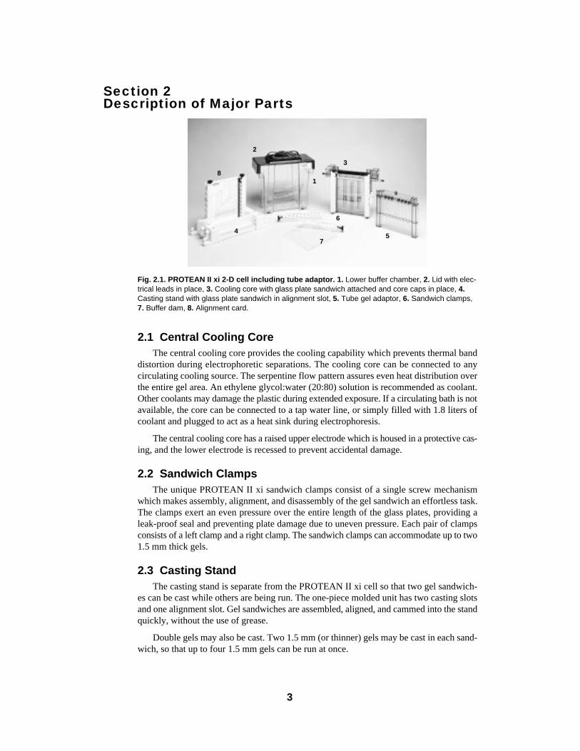
Fig. 2.1. PROTEAN II xi 2-D cell including tube adaptor. 1. Lower buffer chamber, 2. Lid with elec-trical leads in place, 3. Cooling core with glass plate sandwich attached and core caps in place, 4.Casting stand with glass plate sandwich in alignment slot, 5. Tube gel adaptor, 6. Sandwich clamps,7. Buffer dam, 8. Alignment card.
2.1 Central Cooling CoreThe central cooling core provides the cooling capability which prevents thermal band
distortion during electrophoretic separations. The cooling core can be connected to anycirculating cooling source. The serpentine flow pattern assures even heat distribution overthe entire gel area. An ethylene glycol:water (20:80) solution is recommended as coolant.Other coolants may damage the plastic during extended exposure. If a circulating bath is notavailable, the core can be connected to a tap water line, or simply filled with 1.8 liters ofcoolant and plugged to act as a heat sink during electrophoresis.
The central cooling core has a raised upper electrode which is housed in a protective cas-ing, and the lower electrode is recessed to prevent accidental damage.
2.2 Sandwich ClampsThe unique PROTEAN II xi sandwich clamps consist of a single screw mechanism
which makes assembly, alignment, and disassembly of the gel sandwich an effortless task.The clamps exert an even pressure over the entire length of the glass plates, providing aleak-proof seal and preventing plate damage due to uneven pressure. Each pair of clampsconsists of a left clamp and a right clamp. The sandwich clamps can accommodate up to two1.5 mm thick gels.
2.3 Casting StandThe casting stand is separate from the PROTEAN II xi cell so that two gel sandwich-
es can be cast while others are being run. The one-piece molded unit has two casting slotsand one alignment slot. Gel sandwiches are assembled, aligned, and cammed into the standquickly, without the use of grease.
Double gels may also be cast. Two 1.5 mm (or thinner) gels may be cast in each sand-wich, so that up to four 1.5 mm gels can be run at once.
3
8
7
6
54
3
2
1
2.4 Upper Buffer ChamberThe completed gel sandwich attaches to the central cooling core so that the outer plate
of the sandwich forms the side of the upper buffer chamber. The inner plate is clampedagainst a rubber gasket on the central cooling core to provide a greaseless, leak-free seal forthe upper buffer. Each sandwich forms one side of the cathode chamber. Tube gel adaptorsalso snap onto the central cooling core to form the upper buffer chamber walls (one adap-tor per side). If only one gel is to be run, an upper buffer dam is attached to the core toform the complete upper buffer chamber. The upper buffer chamber will hold approxi-mately 350 ml of buffer when full.
2.5 Lower Buffer ChamberThe lower buffer chamber of the PROTEAN II xi cell encloses the unit and provides sta-
bility during electrophoresis. The molded unit requires a minimum buffer volume of only1.1 liters for 20 cm plates, while providing excellent heat exchange through the centralcooling core.
2.6 LidCombined with the lower buffer chamber, the lid acts to fully enclose the PROTEAN
II xi cell during electrophoresis, thus providing electrical insulation. The lid cannot beremoved without disconnecting the electrical circuit. It can be placed on the lower cham-ber in only one alignment, so that the anode and cathode connections cannot be accidentallyreversed. The lid also holds the coiled electrical leads when not in use.
2.7 Tube Gel AdaptorThe tube gel adaptor clamps onto the central cooling core in one easy motion and pro-
vides a leak-proof seal for the upper buffer chamber at voltages up to 1,000 V (especiallyuseful for 2-D applications). The molded construction produces a lightweight, yet durableadaptor unit, which has a gel tube locator at the bottom to hold the tubes in a vertical ori-entation. Each adaptor can hold up to 8 tubes (from 1.0 mm ID to 6 mm ID); 16 tube gelscan be run at once using two tube adaptors.
Note: The upper buffer dam may not be used opposite a tube gel adaptor.
2.8 Alignment CardThe alignment card greatly simplifies sandwich assembly by keeping the spacers upright
during sandwich alignment. A sandwich is assembled by placing two spacers on top of thelarge outer plate. The alignment card is placed between the two spacers, and the shorter innerplate is then placed on top. Following attachment of the clamps, the sandwich assembly istransferred to the alignment slot of the casting stand for final adjustments.
Section 3Assembling the Glass Plate Sandwiches
3.1 Assembling Single SandwichesNote: Instructions for assembling 16 cm and 20 cm sandwiches are identical, except,of course, for the lengths of the components. To insure proper alignment, make sure allplates and spacers are clean and dry before assembly. The PROTEAN II xi plate wash-er/holder simplifies glass plate washing and also makes an ideal storage system forclean, dry glass plates. Each plate holder will accommodate up to 8 PROTEAN II xi platesor up to 18 Mini-PROTEAN® II plates.
4
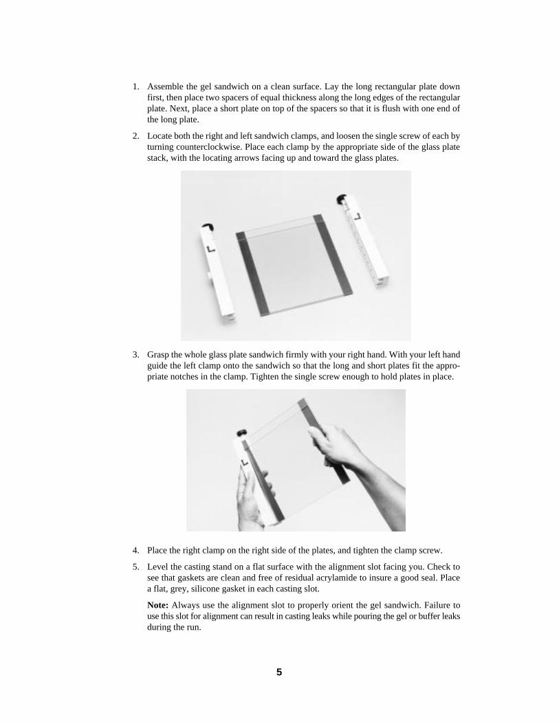
1. Assemble the gel sandwich on a clean surface. Lay the long rectangular plate downfirst, then place two spacers of equal thickness along the long edges of the rectangularplate. Next, place a short plate on top of the spacers so that it is flush with one end ofthe long plate.
2. Locate both the right and left sandwich clamps, and loosen the single screw of each byturning counterclockwise. Place each clamp by the appropriate side of the glass platestack, with the locating arrows facing up and toward the glass plates.
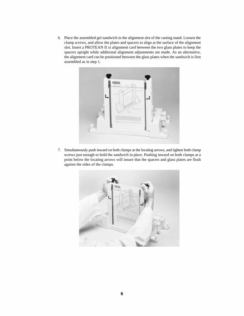
3. Grasp the whole glass plate sandwich firmly with your right hand. With your left handguide the left clamp onto the sandwich so that the long and short plates fit the appro-priate notches in the clamp. Tighten the single screw enough to hold plates in place.
4. Place the right clamp on the right side of the plates, and tighten the clamp screw.
5. Level the casting stand on a flat surface with the alignment slot facing you. Check tosee that gaskets are clean and free of residual acrylamide to insure a good seal. Placea flat, grey, silicone gasket in each casting slot.
Note: Always use the alignment slot to properly orient the gel sandwich. Failure touse this slot for alignment can result in casting leaks while pouring the gel or buffer leaksduring the run.
5
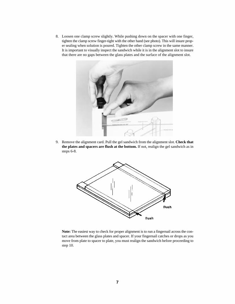
6. Place the assembled gel sandwich in the alignment slot of the casting stand. Loosen theclamp screws, and allow the plates and spacers to align at the surface of the alignmentslot. Insert a PROTEAN II xi alignment card between the two glass plates to keep thespacers upright while additional alignment adjustments are made. As an alternative,the alignment card can be positioned between the glass plates when the sandwich is firstassembled as in step 1.
7. Simultaneously push inward on both clamps at the locating arrows, and tighten both clampscrews just enough to hold the sandwich in place. Pushing inward on both clamps at apoint below the locating arrows will insure that the spacers and glass plates are flushagainst the sides of the clamps.
6
8. Loosen one clamp screw slightly. While pushing down on the spacer with one finger,tighten the clamp screw finger-tight with the other hand (see photo). This will insure prop-er sealing when solution is poured. Tighten the other clamp screw in the same manner.It is important to visually inspect the sandwich while it is in the alignment slot to insurethat there are no gaps between the glass plates and the surface of the alignment slot.
9. Remove the alignment card. Pull the gel sandwich from the alignment slot. Check thatthe plates and spacers are flush at the bottom. If not, realign the gel sandwich as insteps 6-8.
Note: The easiest way to check for proper alignment is to run a fingernail across the con-tact area between the glass plates and spacer. If your fingernail catches or drops as youmove from plate to spacer to plate, you must realign the sandwich before proceeding tostep 10.
7
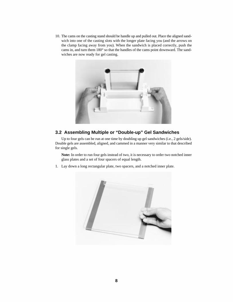
10. The cams on the casting stand should be handle up and pulled out. Place the aligned sand-wich into one of the casting slots with the longer plate facing you (and the arrows onthe clamp facing away from you). When the sandwich is placed correctly, push thecams in, and turn them 180° so that the handles of the cams point downward. The sand-wiches are now ready for gel casting.
3.2 Assembling Multiple or “Double-up” Gel SandwichesUp to four gels can be run at one time by doubling up gel sandwiches (i.e., 2 gels/side).
Double gels are assembled, aligned, and cammed in a manner very similar to that describedfor single gels.
Note: In order to run four gels instead of two, it is necessary to order two notched innerglass plates and a set of four spacers of equal length.
1. Lay down a long rectangular plate, two spacers, and a notched inner plate.
8
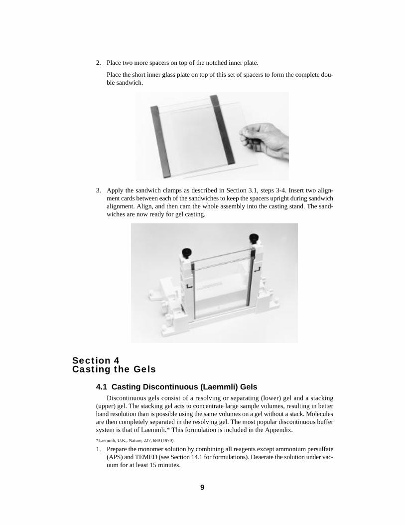
2. Place two more spacers on top of the notched inner plate.
Place the short inner glass plate on top of this set of spacers to form the complete dou-ble sandwich.
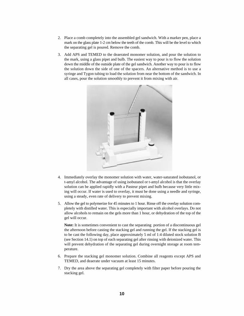
3. Apply the sandwich clamps as described in Section 3.1, steps 3-4. Insert two align-ment cards between each of the sandwiches to keep the spacers upright during sandwichalignment. Align, and then cam the whole assembly into the casting stand. The sand-wiches are now ready for gel casting.
Section 4Casting the Gels
4.1 Casting Discontinuous (Laemmli) GelsDiscontinuous gels consist of a resolving or separating (lower) gel and a stacking
(upper) gel. The stacking gel acts to concentrate large sample volumes, resulting in betterband resolution than is possible using the same volumes on a gel without a stack. Moleculesare then completely separated in the resolving gel. The most popular discontinuous buffersystem is that of Laemmli.* This formulation is included in the Appendix.
*Laemmli, U.K., Nature, 227, 680 (1970).
1. Prepare the monomer solution by combining all reagents except ammonium persulfate(APS) and TEMED (see Section 14.1 for formulations). Deaerate the solution under vac-uum for at least 15 minutes.
9
2. Place a comb completely into the assembled gel sandwich. With a marker pen, place amark on the glass plate 1-2 cm below the teeth of the comb. This will be the level to whichthe separating gel is poured. Remove the comb.
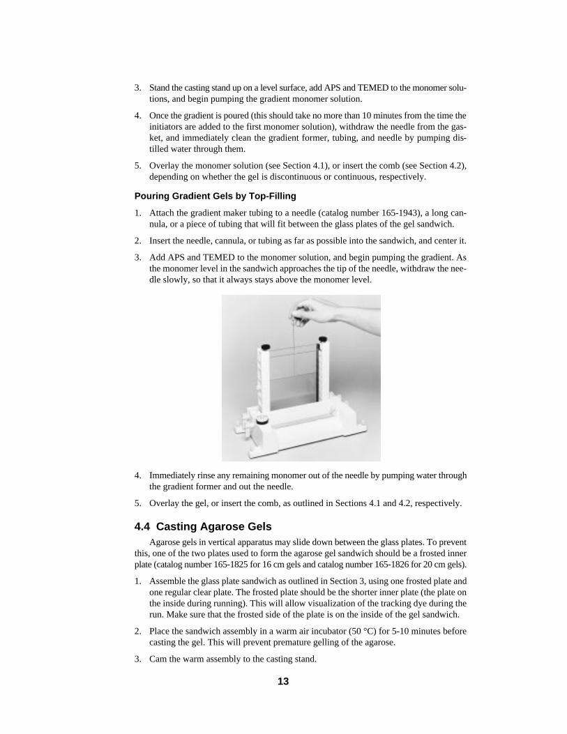
3. Add APS and TEMED to the deaerated monomer solution, and pour the solution tothe mark, using a glass pipet and bulb. The easiest way to pour is to flow the solutiondown the middle of the outside plate of the gel sandwich. Another way to pour is to flowthe solution down the side of one of the spacers. An alternative method is to use asyringe and Tygon tubing to load the solution from near the bottom of the sandwich. Inall cases, pour the solution smoothly to prevent it from mixing with air.
4. Immediately overlay the monomer solution with water, water-saturated isobutanol, ort-amyl alcohol. The advantage of using isobutanol or t-amyl alcohol is that the overlaysolution can be applied rapidly with a Pasteur pipet and bulb because very little mix-ing will occur. If water is used to overlay, it must be done using a needle and syringe,using a steady, even rate of delivery to prevent mixing.
5. Allow the gel to polymerize for 45 minutes to 1 hour. Rinse off the overlay solution com-pletely with distilled water. This is especially important with alcohol overlays. Do notallow alcohols to remain on the gels more than 1 hour, or dehydration of the top of thegel will occur.
Note: It is sometimes convenient to cast the separating portion of a discontinuous gelthe afternoon before casting the stacking gel and running the gel. If the stacking gel isto be cast the following day, place approximately 5 ml of 1:4 diluted stock solution B(see Section 14.1) on top of each separating gel after rinsing with deionized water. Thiswill prevent dehydration of the separating gel during overnight storage at room tem-perature.
6. Prepare the stacking gel monomer solution. Combine all reagents except APS andTEMED, and deaerate under vacuum at least 15 minutes.
7. Dry the area above the separating gel completely with filter paper before pouring thestacking gel.
10

8. Place a comb in the gel sandwich, and tilt it so that the teeth are at a slight (~10°) angle.This will prevent air from being trapped under the comb teeth while pouring themonomer solutions.
9. Add APS and TEMED to the degassed monomer solution, and pour the solution downthe spacer nearest the upturned side of the comb. Pour until all the teeth have beencovered by solution. Then properly align the comb in the sandwich, and add monomerto fill completely.
Generally, an overlay solution is not necessary for polymerization when a comb is inplace.
10. Allow the gel to polymerize 30-45 minutes. Remove the comb by pulling it straightup slowly and gently.
11. Rinse the wells completely with distilled water. The gels are now ready to be attachedto the central cooling core, the sample loaded, and the gels run.
11

4.2 Casting Continuous GelsContinuous gels are ones in which the entire gel is of one composition. This type of gel
is often used in non-denaturing (native) buffer systems.
1. Prepare the monomer solution. Combine all reagents except APS and TEMED. Degasunder vacuum for at least 15 minutes.
2. Place a comb in the glass sandwich so that the teeth are tilted at approximately a 10° angle.
3. Add APS and TEMED to the degassed monomer solution, and use a pipet and bulb topour the solution down the spacer nearest to the upturned side of the comb. Pour untilthe bottoms of all the teeth are covered. Then adjust the comb to its proper position. Addmonomer solution to fill the sandwich completely. No overlay solution is necessary.
4. Let the gel polymerize for 45 minutes to 1 hour. The gel is now ready to load and run.Remove the comb, and rinse thoroughly with distilled water.
4.3 Casting Gradient GelsPolyacrylamide concentration gradients, made with an external gradient former (Model
385, catalog number 165-2000), can be introduced into the PROTEAN II xi gel sandwichassembly either from the bottom or from the top. A peristaltic pump is required for intro-duction from the bottom. Introduction from the top can be done by gravity flow or with aperistaltic pump. Follow the gradient former instructions for formulating the gradient. If gra-dients are pumped into the gel sandwich from the bottom, the low density solution (low per-cent monomer) must enter first. If the gradient enters from the top, the high density solution(high percent monomer) enters first.
Pouring Gradient Gels from the Bottom
1. After assembling the gel sandwich as described in Section 4, attach the gradient formertubing to a gradient pouring needle (catalog number 165-2007).
2. Cam the gel sandwich to the casting stand, turn the casting stand on its side, locate thebottom filling ports directly under the space in the sandwich, and insert the bottom-fillneedle through the rubber gasket, so that it protrudes about 2 mm into the sandwich. Makesure the needle opening faces one of the glass plates.
12
3. Stand the casting stand up on a level surface, add APS and TEMED to the monomer solu-tions, and begin pumping the gradient monomer solution.
4. Once the gradient is poured (this should take no more than 10 minutes from the time theinitiators are added to the first monomer solution), withdraw the needle from the gas-ket, and immediately clean the gradient former, tubing, and needle by pumping dis-tilled water through them.
5. Overlay the monomer solution (see Section 4.1), or insert the comb (see Section 4.2),depending on whether the gel is discontinuous or continuous, respectively.
Pouring Gradient Gels by Top-Filling
1. Attach the gradient maker tubing to a needle (catalog number 165-1943), a long can-nula, or a piece of tubing that will fit between the glass plates of the gel sandwich.
2. Insert the needle, cannula, or tubing as far as possible into the sandwich, and center it.
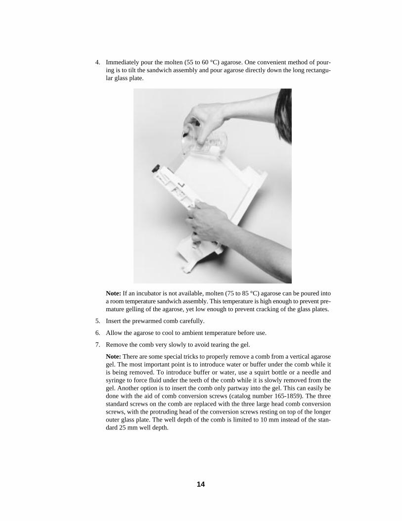
3. Add APS and TEMED to the monomer solution, and begin pumping the gradient. Asthe monomer level in the sandwich approaches the tip of the needle, withdraw the nee-dle slowly, so that it always stays above the monomer level.
4. Immediately rinse any remaining monomer out of the needle by pumping water throughthe gradient former and out the needle.
5. Overlay the gel, or insert the comb, as outlined in Sections 4.1 and 4.2, respectively.
4.4 Casting Agarose GelsAgarose gels in vertical apparatus may slide down between the glass plates. To prevent
this, one of the two plates used to form the agarose gel sandwich should be a frosted innerplate (catalog number 165-1825 for 16 cm gels and catalog number 165-1826 for 20 cm gels).
1. Assemble the glass plate sandwich as outlined in Section 3, using one frosted plate andone regular clear plate. The frosted plate should be the shorter inner plate (the plate onthe inside during running). This will allow visualization of the tracking dye during therun. Make sure that the frosted side of the plate is on the inside of the gel sandwich.
2. Place the sandwich assembly in a warm air incubator (50 °C) for 5-10 minutes beforecasting the gel. This will prevent premature gelling of the agarose.
3. Cam the warm assembly to the casting stand.
13
4. Immediately pour the molten (55 to 60 °C) agarose. One convenient method of pour-ing is to tilt the sandwich assembly and pour agarose directly down the long rectangu-lar glass plate.
Note: If an incubator is not available, molten (75 to 85 °C) agarose can be poured intoa room temperature sandwich assembly. This temperature is high enough to prevent pre-mature gelling of the agarose, yet low enough to prevent cracking of the glass plates.
5. Insert the prewarmed comb carefully.
6. Allow the agarose to cool to ambient temperature before use.
7. Remove the comb very slowly to avoid tearing the gel.
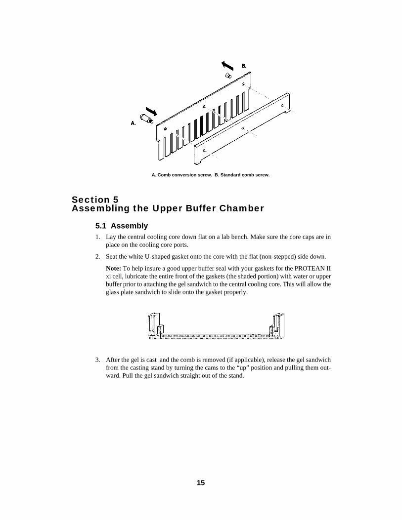
Note: There are some special tricks to properly remove a comb from a vertical agarosegel. The most important point is to introduce water or buffer under the comb while itis being removed. To introduce buffer or water, use a squirt bottle or a needle andsyringe to force fluid under the teeth of the comb while it is slowly removed from thegel. Another option is to insert the comb only partway into the gel. This can easily bedone with the aid of comb conversion screws (catalog number 165-1859). The threestandard screws on the comb are replaced with the three large head comb conversionscrews, with the protruding head of the conversion screws resting on top of the longerouter glass plate. The well depth of the comb is limited to 10 mm instead of the stan-dard 25 mm well depth.
14
Section 5Assembling the Upper Buffer Chamber
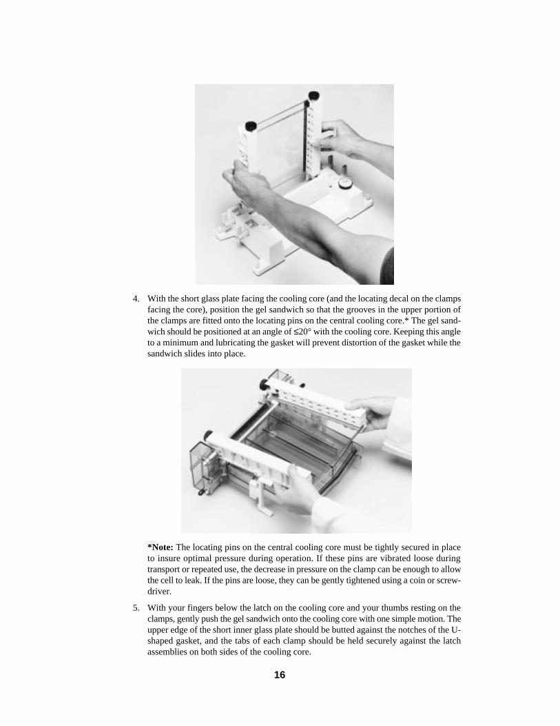
5.1 Assembly1. Lay the central cooling core down flat on a lab bench. Make sure the core caps are in
place on the cooling core ports.
2. Seat the white U-shaped gasket onto the core with the flat (non-stepped) side down.
Note: To help insure a good upper buffer seal with your gaskets for the PROTEAN IIxi cell, lubricate the entire front of the gaskets (the shaded portion) with water or upperbuffer prior to attaching the gel sandwich to the central cooling core. This will allow theglass plate sandwich to slide onto the gasket properly.
3. After the gel is cast and the comb is removed (if applicable), release the gel sandwichfrom the casting stand by turning the cams to the “up” position and pulling them out-ward. Pull the gel sandwich straight out of the stand.
15
A. Comb conversion screw. B. Standard comb screw.
4. With the short glass plate facing the cooling core (and the locating decal on the clampsfacing the core), position the gel sandwich so that the grooves in the upper portion ofthe clamps are fitted onto the locating pins on the central cooling core.* The gel sand-wich should be positioned at an angle of ≤20° with the cooling core. Keeping this angleto a minimum and lubricating the gasket will prevent distortion of the gasket while thesandwich slides into place.
*Note: The locating pins on the central cooling core must be tightly secured in placeto insure optimal pressure during operation. If these pins are vibrated loose duringtransport or repeated use, the decrease in pressure on the clamp can be enough to allowthe cell to leak. If the pins are loose, they can be gently tightened using a coin or screw-driver.
5. With your fingers below the latch on the cooling core and your thumbs resting on theclamps, gently push the gel sandwich onto the cooling core with one simple motion. Theupper edge of the short inner glass plate should be butted against the notches of the U-shaped gasket, and the tabs of each clamp should be held securely against the latchassemblies on both sides of the cooling core.
16
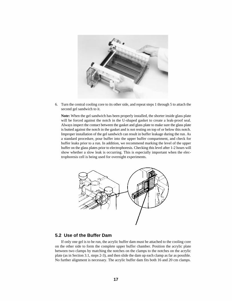
6. Turn the central cooling core to its other side, and repeat steps 1 through 5 to attach thesecond gel sandwich to it.
Note: When the gel sandwich has been properly installed, the shorter inside glass platewill be forced against the notch in the U-shaped gasket to create a leak-proof seal.Always inspect the contact between the gasket and glass plate to make sure the glass plateis butted against the notch in the gasket and is not resting on top of or below this notch.Improper installation of the gel sandwich can result in buffer leakage during the run. Asa standard procedure, pour buffer into the upper buffer compartment, and check forbuffer leaks prior to a run. In addition, we recommend marking the level of the upperbuffer on the glass plates prior to electrophoresis. Checking this level after 1-2 hours willshow whether a slow leak is occurring. This is especially important when the elec-trophoresis cell is being used for overnight experiments.
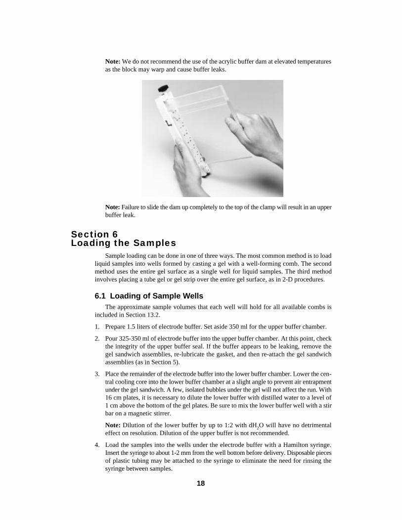
5.2 Use of the Buffer DamIf only one gel is to be run, the acrylic buffer dam must be attached to the cooling core
on the other side to form the complete upper buffer chamber. Position the acrylic platebetween two clamps by matching the notches on the clamps to the notches on the acrylicplate (as in Section 3.1, steps 2-3), and then slide the dam up each clamp as far as possible.No further alignment is necessary. The acrylic buffer dam fits both 16 and 20 cm clamps.
17
18
Note: We do not recommend the use of the acrylic buffer dam at elevated temperaturesas the block may warp and cause buffer leaks.
Note: Failure to slide the dam up completely to the top of the clamp will result in an upperbuffer leak.
Section 6Loading the Samples
Sample loading can be done in one of three ways. The most common method is to loadliquid samples into wells formed by casting a gel with a well-forming comb. The secondmethod uses the entire gel surface as a single well for liquid samples. The third methodinvolves placing a tube gel or gel strip over the entire gel surface, as in 2-D procedures.
6.1 Loading of Sample WellsThe approximate sample volumes that each well will hold for all available combs is
included in Section 13.2.
1. Prepare 1.5 liters of electrode buffer. Set aside 350 ml for the upper buffer chamber.
2. Pour 325-350 ml of electrode buffer into the upper buffer chamber. At this point, checkthe integrity of the upper buffer seal. If the buffer appears to be leaking, remove thegel sandwich assemblies, re-lubricate the gasket, and then re-attach the gel sandwichassemblies (as in Section 5).
3. Place the remainder of the electrode buffer into the lower buffer chamber. Lower the cen-tral cooling core into the lower buffer chamber at a slight angle to prevent air entrapmentunder the gel sandwich. A few, isolated bubbles under the gel will not affect the run. With16 cm plates, it is necessary to dilute the lower buffer with distilled water to a level of1 cm above the bottom of the gel plates. Be sure to mix the lower buffer well with a stirbar on a magnetic stirrer.
Note: Dilution of the lower buffer by up to 1:2 with dH2O will have no detrimentaleffect on resolution. Dilution of the upper buffer is not recommended.
4. Load the samples into the wells under the electrode buffer with a Hamilton syringe.Insert the syringe to about 1-2 mm from the well bottom before delivery. Disposable piecesof plastic tubing may be attached to the syringe to eliminate the need for rinsing thesyringe between samples.
Note: The sample buffer must contain either 10% sucrose or glycerol in order to under-lay the sample in the well without mixing.
5. An easier method of sample loading is to use an Eppendorf-like pipettor and disposabletips. To accomplish this successfully, use the optional beveled short plate (catalog num-ber 165-1827 for 16 cm and 165-1828 for 20 cm) so that you can insert the pipet tip fur-ther into the well before sample delivery. This will prevent inter-well mixing of samples.Or, use the Bio-Rad Prot-Elec tips (catalog number 223-9915 or 223-9917), which aredesigned for loading samples into wells.
6.2 Loading a Single Sample Per GelIn this procedure, a gel is cast without using a comb, forming a flat gel surface. This gel
is cast with an overlay solution. This type of sample application can be used for preparativepurposes, but it is most often used in blotting applications. After electrophoresis, the sam-ple is transferred electrophoretically to a membrane, which then can be cut into severalidentical strips for analysis. Follow the instructions for casting the separating portion of adiscontinuous gel (Section 4.1), except pour the gel nearly to the top of the sandwich. Allowjust enough room for sample loading. (A stacking gel may also be added to this type ofgel.)
1. Prepare electrode buffer, and add to lower reservoir as in Section 6.1. Place the centralcooling core in the lower chamber, and add electrode buffer to the upper reservoir cham-ber.
2. The sample may be loaded with an Eppendorf-type pipettor, with a needle and syringe,or with a Hamilton syringe. Start at one end of the gel, and deliver the sample gently andevenly over the entire length of the gel. Layer the sample as closely as possible (1-2 mm)to the surface of the gel.
6.3 Gels as SamplesAll two-dimensional techniques involve this variation of sample loading. Either a cylin-
drical gel or a strip of a slab gel may be placed on top of a slab gel for separation into a sec-ond dimension. This procedure is described in detail in Section 10.
Section 7Running the Gel
1. Place the lid on top of the lower buffer chamber to enclose the PROTEAN II xi cell fully.Note that the lid can be placed only in one orientation, so that the anode and cathode con-nections cannot be reversed.
2. Attach the electrical leads to a suitable power supply, such as those in Section 13.6,with the proper polarity (this connection could accidently be reversed).
3. Apply power to the PROTEAN II xi cell and begin electrophoresis. As a safety pre-caution, always set voltage, current, and power limits when possible. See the Appendix(Section 14.4) for specific running conditions.
19
Section 8Set-up Options
8.1 Buffer RecirculationBuffer recirculation is sometimes necessary for extended electrophoretic runs or for
use with certain weak buffer systems.
To recirculate electrode buffer from the lower to the upper chambers, a few simplemodifications have to be made to the PROTEAN II xi cell.
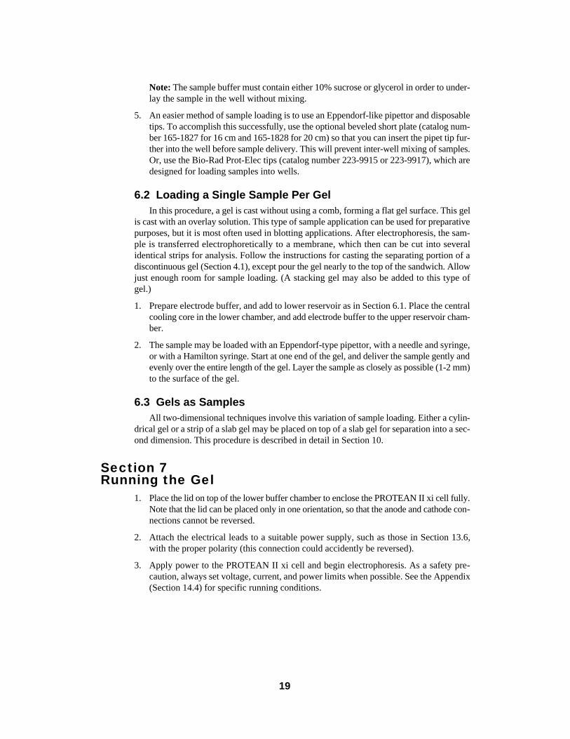
1. Locate the recirculation port tabs on the lid of the cell. The tab directly above the upperbuffer chamber and one of the tabs directly above the lower buffer chamber must beremoved. Remove by grasping with a pair of pliers and twisting the tab until it breaksoff (see photo).
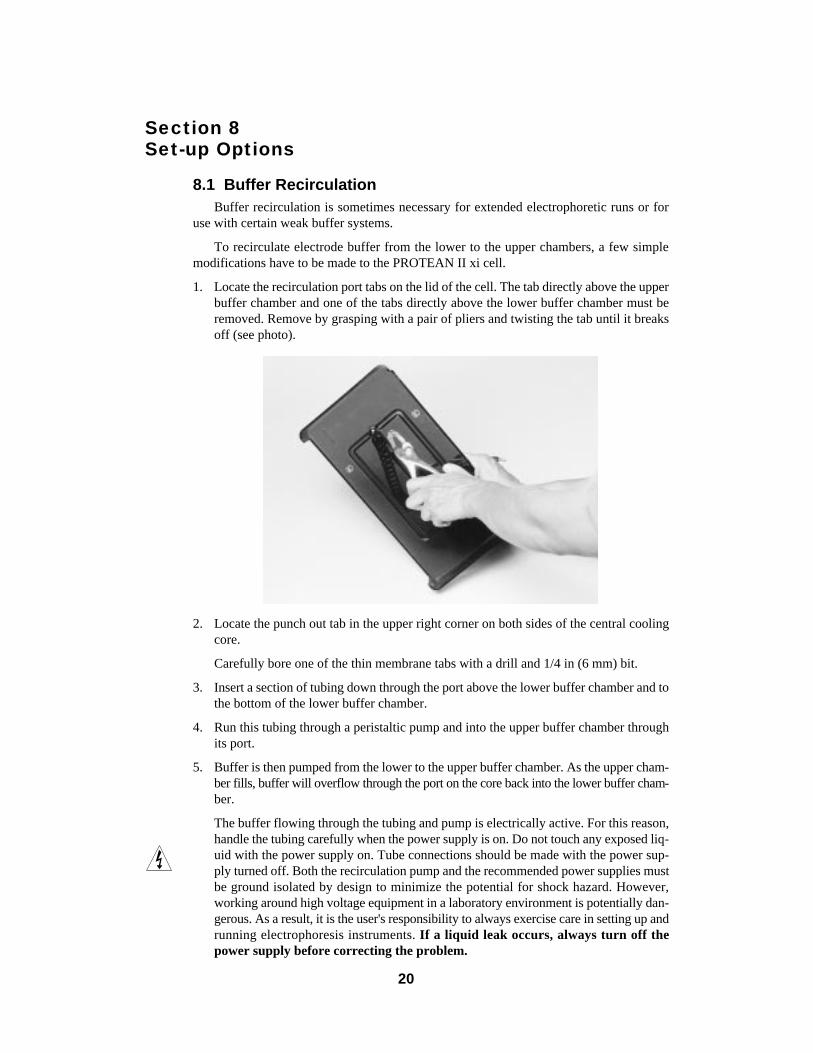
2. Locate the punch out tab in the upper right corner on both sides of the central coolingcore.
Carefully bore one of the thin membrane tabs with a drill and 1/4 in (6 mm) bit.
3. Insert a section of tubing down through the port above the lower buffer chamber and tothe bottom of the lower buffer chamber.
4. Run this tubing through a peristaltic pump and into the upper buffer chamber throughits port.
5. Buffer is then pumped from the lower to the upper buffer chamber. As the upper cham-ber fills, buffer will overflow through the port on the core back into the lower buffer cham-ber.
The buffer flowing through the tubing and pump is electrically active. For this reason,handle the tubing carefully when the power supply is on. Do not touch any exposed liq-uid with the power supply on. Tube connections should be made with the power sup-ply turned off. Both the recirculation pump and the recommended power supplies mustbe ground isolated by design to minimize the potential for shock hazard. However,working around high voltage equipment in a laboratory environment is potentially dan-gerous. As a result, it is the user's responsibility to always exercise care in setting up andrunning electrophoresis instruments. If a liquid leak occurs, always turn off thepower supply before correcting the problem.
20
Note: Recirculation can only be used with continuous buffer systems (i.e., systems inwhich the anode buffer and cathode buffer are the same).
8.2 Cooling OptionsThe cooling core may be used in any of the following ways:
1. The core can be connected to any circulating cooler. Any common anti-freeze or ethy-lene:glycol (20:80) may be circulated through the core. Do not use ethanol or methanolfor coolant. For most SDS-PAGE and 2-D applications temperature should be setbetween 10 and 15 °C. For some specialized applications employing native or non-denaturing gel systems, in which temperature sensitive enzymes or other labile pro-teins are to be separated, the system can be cooled to 2-4 °C. For these applications,greatest heat transfer efficiency is achieved by circulating coolant through the core at2 °C and filling the lower buffer chamber to the top of the slab gels. The lower bufferis continually circulated by stirring.
2. The core may be filled with coolant and the circulation ports plugged off with the corecaps. The coolant will act as a heat sink during electrophoresis. This option works espe-cially well for SDS-PAGE.
3. Distilled tap water may be circulated through the core.
4. Temperature of the coolant can be monitored by placing a thermometer through one ofthe ports in the lid of the PROTEAN II xi cell. The temperature of the upper and lowerbuffers will equilibrate to the temperature of the coolant in about 1/2 hour. Removethe tab in the lid as in Section 8.1, step 1.
5. During periods of non-use, the cooling core can be left filled with coolant or water andcapped.
21
Section 9Removing the Gels
1. After electrophoresis is complete, turn off the power supply, and disconnect the elec-trical leads.
2. Disconnect coolant hoses from the core (if applicable), and plug off the ports.
3. Remove the cell lid, and carefully pull the central cooling core out of the lower cham-ber. Pour off the upper buffer.
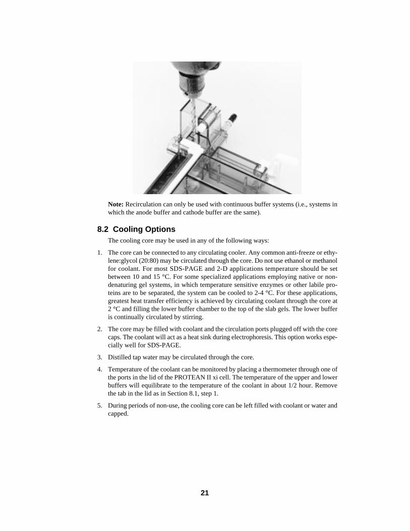
4. Lay the central cooling core on its side, and remove the sandwich assembly in the fol-lowing manner:
With your index fingers below the sandwich clamps and your thumbs resting on the latch-es in the cooling core, gently remove the assembly by pulling up toward you (in a man-ner opposite to the way it was attached in Section 5). Pull the sandwich assembly offthe locating pins on the top of the cooling core.
5. Loosen the single screw of each clamp, and remove the clamps from the glass plates.
6. Push one of the spacers of the sandwich out to the side of the plates without removingit.
7. Gently twist the spacer so that the upper glass plate pulls away from the gel.
22
8. Remove the gel by gently grasping two corners of the gel and lifting off, or alternatively,place the gel and glass plate under fixative solution, and agitate gently until the gelseparates from the glass plate.
9. If the gel is to be stained later, place it in a suitable container with fixative solution(e.g., 40% methanol/10% acetic acid). See Section 14.5 for staining formulations. If theproteins on the gel are to be electrophoretically transferred to a membrane, place the gelin equilibration buffer (do not put in fixative).
Note: The Model 556 Gel Destainer (catalog number 165-2010) is ideal for rapiddestaining (less than 1 hour) of Coomassie blue stained gels.
Section 10Two-Dimensional Electrophoresis
Two-dimensional electrophoresis can provide exceptionally high resolution of the pro-tein components in a complex sample. It is capable of resolving several thousand individ-ual protein species. Based on the method of O’Farrell, the first dimension is isoelectricfocusing (IEF), during which proteins are separated according to their isoelectric points. Thesecond dimension is SDS-polyacrylamide gel electrophoresis, in which proteins are sepa-rated on the basis of their molecular size. Since O’Farrell’s original work, many variationsof the 2-D procedure have been reported which may also be used. The following procedureis based on the work of Dr. Denis Hochstrasser.6-7 The flow chart (Section 10.1) outlines insequence the essential steps of 2-D electrophoresis and refers to the solution protocols inSection 14.
Note: This section focuses on 2-D electrophoresis. The PROTEAN II xi cell may alsobe used for one-dimensional tube gel electrophoresis. One can adapt this protocol to anyof the common electrophoretic techniques, using either continuous or discontinuousbuffer systems, by following the instructions for casting, loading, and running tubegels.
23
10.1 Sequence of Steps for 2-D Protocol
Step Time Interval
Day 1
1. Pour tube gels ..................................................................... polymerize 2 hours
2. Prepare electrolytes, prepare and load samples ................. 1⁄2 hour-1 hour
3. Electrophorese at 200 V constant voltage .......................... 2 hours
4. Electrophorese at 500 V constant voltage .......................... 2 hours
5. Electrophorese at 800 V constant voltage .......................... 16 hours (overnight)
6. Cast slab gels for second dimension gels whilefirst dimension gels are running ......................................... 1 hour
7. Prepare second dimension running buffer .......................... 10 minutes
Day 2
8. Disassemble tube apparatus................................................ 2 minutes
9. Extrude gels from tubes and overlay tube gelsonto slab gels ...................................................................... 25 minutes
10. Electrophorese the second-dimension SDS gel .................. 4-41⁄2 hours
10.2 Protocol for IEF First Dimension
Casting IEF Tube Gels
For reproducible 2-D gels, it is essential that the IEF tube gels be precisely the same lengthand that polymerization be identical from day to day. Care must be taken in pouring the gelsto the same height so that the polymerization height will be the same from tube to tube. Anoverlay step is not necessary in IEF first dimension tube gels. The meniscus formed on topof the gel will not influence the pH gradient or the resolution of the bands. The advantageof not overlaying is the formation of gels of more uniform length and composition. Stocksolutions and formulations for first dimension tube gels are given in Section 14.
1. Mark the capillary tubes (1.5 mm ID, 6.0 mm OD, 180 mm, catalog number 165-3138) with a laboratory marker 14.0 cm from one end.
2. Connect each capillary tube to a 1 ml syringe using a small piece of Tygon tubing 3⁄16"ID x 1⁄4" OD, and approximately 2 cm in length (not included). Fill either a test tuberack or a level casting stand, such as Bio-Rad’s Model 225 Tube Gel Casting Stand (cat-alog number 165-2020) with a disposable 12 x 75 mm test tube for each capillary tube.Insert a capillary tube/syringe assembly into each test tube.
3. Prepare the first dimension monomer solution and degas well. (The removal of molec-ular oxygen by degassing is essential for reproducible polymerization.)
Warning: Always wear gloves to prevent exposure to acrylamide.
4. Add the APS and TEMED, and swirl 8 to 10 times. Working quickly, pipet 1 ml of acry-lamide solution into each test tube. Using the syringe, pull up the liquid in each tube tothe 14.0 cm mark. Let the capillary tubes sit undisturbed, with syringes attached, for 2hours at room temperature to allow complete polymerization to occur.
24
5. After polymerization is completed, remove the capillary tubes from each test tube.Remove the syringe and Tygon tubing. Press and rotate the bottom of the capillarytube squarely down on a piece of Parafilm™ to remove excess acrylamide. Wipe off theexcess acrylamide.
6. Inspect the gels before loading; bubbles within the gel prevent focusing and these gelsshould be discarded.
Note: Alternative methods for filling capillary tubes can be used, such as wrappingthe bottom end of the capillary tube with two layers of Parafilm™ laboratory film andfilling using a syringe and fine gauge cannula (gel tube loading needle, 165-1943). Thecannula should be long enough to reach the bottom of the tube. Slowly inject the acry-lamide solution into the bottom of the tube, withdrawing the cannula as the acrylamideenters the tube. Fill to the mark on the tube.
Sample Preparation and Loading
Sample preparation prior to isoelectric focusing is one of the most important steps forobtaining reproducible two-dimensional electrophoresis gels. There is no method which isoptimal for every sample, and it may be necessary to experiment with different protein sol-ubilization methods to determine which is best.
1. Prepare the first dimension running solutions as described in Section 14.
2. Prepare the IEF sample concentrate solution A and/or iso-urea solution E as describedin Section 14. These solutions should be prepared fresh, or frozen in aliquots.
Note: Sample loads above 400 µg total protein may cause loss of resolution in the sec-ond dimension slab gel.
3. Replace the notched white gaskets with the tube adaptor gaskets specifically designedfor use during the first dimension of 2-D electrophoresis. Do not lubricate or wet thered tube adaptor gaskets.
Note: Tube gels have a much higher resistance than slab gels due to their small diam-eter. Since current seeks the path of least resistance, a current leak may occur if thereis an alternative path of conductance such as a wet gasket. A current leak is a safety haz-ard to the researcher as well as the equipment.
4. Attach the tube gel adaptor to the cooling core in the same manner that a slab gel sand-wich is attached (see Section 5.1). Sandwich clamps are not needed to attach the tubeadaptor to the core. Finish assembling the upper buffer chamber with a second tubegel adaptor. Because of the higher voltages required for focusing, we recommendalways using two tube gel adaptors and not the buffer dam for focusing.
25
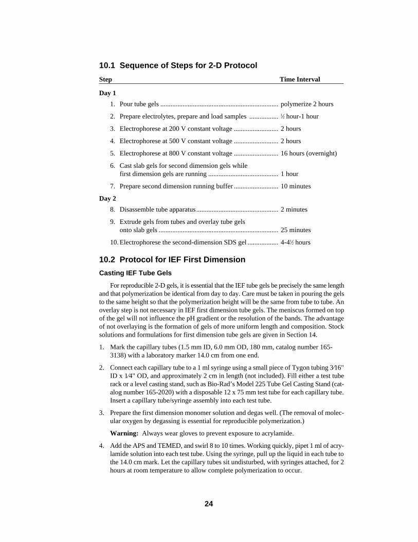
Note: Buffer leakage during isoelectric focusing can result in damage to the cooling core.It is important to check for buffer leaks by monitoring both the current and the upperbuffer level. During the course of a normal IEF run, the current decreases as the resis-tance of the gel increases, the pH gradient is established, and the upper buffer level ismaintained. If a buffer leak should occur, the current will increase, and the level ofupper buffer may decrease. Do not exceed 1,000 V as the maximum focusing voltage.
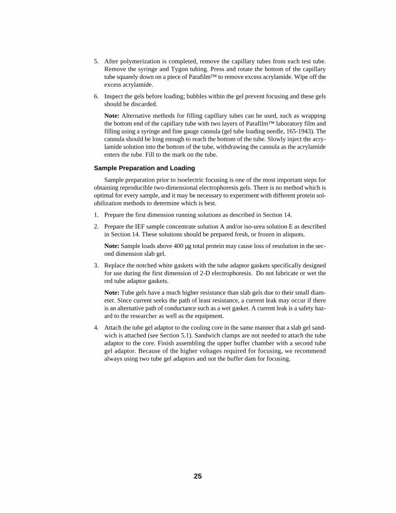
5. Insert the tube gels into the tube gel adaptor, using the gel tube locator at the bottom ofthe unit to align the tubes. Plug any unused tube holes with a stopper.
6. Prepare the sample just before loading. The amount of denaturing sample solution Aand/or iso-urea solution E will depend upon the protein concentration of sample and uponthe type of sample. An initial starting ratio of 1 µl IEF sample concentrate for every 10 µlsample can be used. For denaturing, samples are heated at 95 °C for 5 minutes then cooledfor 2 minutes at room temperature before loading or before adding iso-urea solution.
7. Load the samples with a Hamilton syringe, or with a Drummond pipet tip. (Generally,15 to 30 µl of final diluted sample is loaded.)
26
8. Carefully overlay the sample with upper electrolyte (20 mM NaOH).
Running the IEF Gels
1. Fill the central cooling core with water or coolant. Cap the inlet and outlet port with thecaps provided.
2. Fill the lower buffer chamber with ~4.5 liters of lower running electrolyte (see Section14). Place on a level surface or leveling table.
3. Lower the cooling core/tube apparatus into the lower chamber of the PROTEAN II xicell. Lower carefully so as not to introduce any air bubbles under the gel tubes. Allbubbles must be removed from the bottom of the tubes to insure proper electrical con-tact.
4. Pour 325-350 ml freshly degassed upper running electrolyte (see Section 14) into theupper buffer chamber, put the lid on, and attach the power cables to the power supply.
5. Run the first dimension gels at room temperature with a constant voltage of 200 voltsfor 2 hours, followed by 500 volts for 2 hours, and then 800 volts overnight (16 hours).As a safety precaution, always set voltage, current, and power limits when possible.
Note: Phycocyanin is a colored protein found in Bio-Rad’s IEF standards (catalognumber 161-0310). Although these standards cannot be used for pI calibration in 2-Dprocedures, because denaturation in urea produces too many peptide spots, the phyco-cyanin is excellent for monitoring the first dimension IEF. It retains its blue color andwill focus in a tight blue band when focusing is finished. Loading one tube with the focus-ing standards is an easy way to monitor the progress of the focusing run.
6. Cast the second dimension SDS slab gel during the running of the first dimension (seeSection 4).
Note: This protocol does not use a stacking gel. However, if a stacking gel is requiredfor a particular application, it should be cast on a level surface. It is important that thesame amount of monomer be used for each stacking gel to insure stacking gels of iden-tical depth. If a comb is not used, as in most 2-D applications, then the stacking gel shouldbe overlaid with 1.0 ml of water saturated sec-butanol. After polymerization is complete,drain off the overlay (or remove the combs), and rinse the gel surface briefly with dis-tilled deionized water.
Extruding Tube Gels
1. After electrophoresis, remove the tube gels from the tube gel adaptor. Rinse both the topand bottom of each gel thoroughly with distilled water. Failure to rinse before extrusionwill result in residual base (NaOH) or acid (phosphoric) on the gel that will interfere withmeasurement of the pH gradient. Place the tubes, in order, into the tube rack, and filleach tube to the top with distilled water.
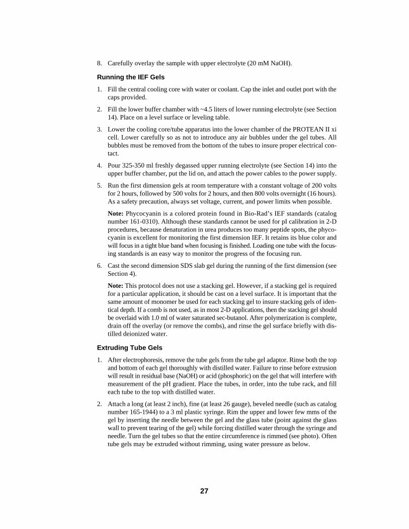
2. Attach a long (at least 2 inch), fine (at least 26 gauge), beveled needle (such as catalognumber 165-1944) to a 3 ml plastic syringe. Rim the upper and lower few mms of thegel by inserting the needle between the gel and the glass tube (point against the glasswall to prevent tearing of the gel) while forcing distilled water through the syringe andneedle. Turn the gel tubes so that the entire circumference is rimmed (see photo). Oftentube gels may be extruded without rimming, using water pressure as below.
27
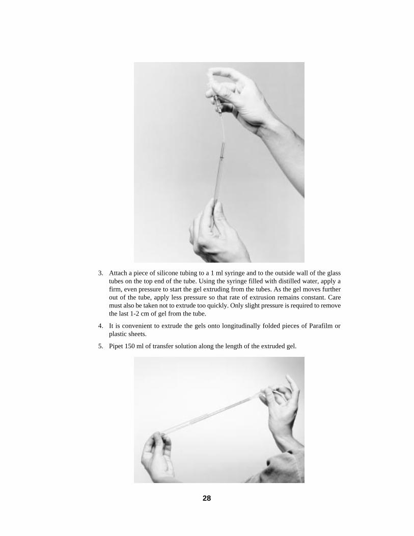
3. Attach a piece of silicone tubing to a 1 ml syringe and to the outside wall of the glasstubes on the top end of the tube. Using the syringe filled with distilled water, apply afirm, even pressure to start the gel extruding from the tubes. As the gel moves furtherout of the tube, apply less pressure so that rate of extrusion remains constant. Caremust also be taken not to extrude too quickly. Only slight pressure is required to removethe last 1-2 cm of gel from the tube.
4. It is convenient to extrude the gels onto longitudinally folded pieces of Parafilm orplastic sheets.
5. Pipet 150 ml of transfer solution along the length of the extruded gel.
28

Embedding of First Dimension onto Second Dimension
Note: When handling gels, it is advisable to wear gloves. First dimension gels tend tobe sticky to the touch and will tear easily.
1. Use of a beveled short glass plate (catalog number 165-1827 for 16 cm cell and165-1828 for 20 cm cell) in the second dimension slab sandwich will greatly improvethe ease of embedding the tube gel on top of the slab gel. Rinse the top of the completedsecond dimension SDS slab gel thoroughly with distilled water, and drain off excesswater. Attach clamp assemblies to cooling core.
2. Using a spatula, direct the gel from the Parafilm to the bevel at the top of the innerglass plate, starting at one side and proceeding across the gel. Place a few drops ofSDS electrode buffer along the top of the tube gel.
3. Use a spatula to seat the tube gel on the slab gel. Check that the tube gel is in contactwith the slab gel over its entire length. Be sure to remove all air bubbles that are betweenthe tube gel and the slab gel. By placing the tube gel directly on top of the seconddimension slab gel, between the glass plates, no agarose overlay is necessary. If thetube gel diameter is greater than the second dimension slab gel thickness, an agarose over-lay may be necessary to insure good contact and to prevent the tube gel from slippingoff the slab gel. The agarose overlay is 1% agarose in 1x stacking gel buffer, diluted 1:4(see Section 14.1, solution C).
Note: If you would like to apply molecular weight standards to the second dimension,we recommend using a 2-D comb for casting the stacking gel. As an alternative, if a stack-ing gel is not desired, you can make a tube gel with a mixture of agarose and Bio-Radstandards. Then simply cut the agarose into pieces, and load a piece directly on top ofthe second dimension slab gel in tandem with the IEF tube gel.
4. Electrophorese the SDS slab gel as in Section 7.
5. Remove the gels as in Section 9.
6. Stain the gels as in Section 14.5.
Note: Tube gels may be frozen for future use or applied directly to a second dimensionslab gel. To freeze a tube gel, place the gel lengthwise in a stoppered tube in an EtOH:dryice bath. Once frozen, gels can be stored at -20 °C.
29
Section 11Maintenance of Equipment
Warning: Exercise extreme caution for acid cleaning wear safety glasses, a lab coat,and rubber gloves. Keep a container of NaCO3 nearby to neutralize spills.
PROTEAN II xi cell chamber, core,clamps
Glass plates, spacers, combs
Glass plates (if more stringent cleaningis required)
Glass tubes
Rinse thoroughly with distilled waterafter every use.
Wash with a laboratory detergent (cata-log number 161-0722), then rinse thor-oughly with distilled water.
Soak in a strong acid solution (chromicacid/sulfuric acid cleaning solution) for≥30 minutes, and then rinse thoroughlywith distilled water. A less toxic alterna-tive is 5% KOH in 100% methanol.
After use, rinse with laboratory detergentsolution, scrub out if possible, then rinsewith distilled H2O. Store glass tubes inchromic/sulfuric acid solution until nextuse. Then rinse thoroughly with distilledwater and dry in forced air or vacuum ovenbefore use.
30
Section 12Troubleshooting Guide – PAGE, SDS-PAGE, 2-D IEF/SDS-PAGE
1. “Smile” effect — bandpattern curves upward atboth sides of the gel.
2. Diffuse tracking dye.
3. Vertical streaking ofprotein.
4. Horizontal streaking(2-D gels).
5. Broad or diffuse proteinbands or spots (2-D).
6. Lateral band spreading.
a. Center of the gel runninghotter than either side.
b Power conditions exces-sive.
a. Decomposition of samplesolution and/or buffer stocksolutions.
b. Diffusion.
a. Sample overload.
b. Sample precipitation.
a. Incomplete solubilizationprior to first dimension.
b. Interfering nucleic acids insample.
a. Diffusion due to slowmigration.
b. Chemical changes due toionic contaminants in urea.
a. Diffusion out of the wellsprior to turning on the cur-rent.
b. Diffusion during migrationthrough the stacking gel.
a. Fill inner core withcoolant.
b. Circulate coolant at 10-15 °C.
c. Decrease power setting.
a. Prepare fresh reagents —maximum shelf life ofaqueous solutions is 30days at 4 °C for buffer andmonomer stocks.
b. If protein bands are diffuseas well as to the trackingdye, increase current by 25-50% and/or increase % Tof resolving gel.*
a. Dilute sample, selectivelyremove predominant pro-tein in the sample, orreduce current by about25% to minimize streaking.
b. Centrifuge sample ordecrease % T of resolvinggel.*
a. If urea/nonionic detergentis not sufficient, use SDSas in Ref. 15.5-2. Centri-fugation of sample may benecessary (up to 100,000 xg for 30 minutes) to removeundissolved particulates.
b. Treat sample with DNaseor RNase as in Ref. 15.5-1.
a. Increase current by 20%.
b. Deionize urea.
a. Minimize the time betweensample application andpower start-up.
b. Increase % T of stackinggel to 4.5% or 5% T, orincrease current by 25%during stacking.*
Problem Cause Solution
31
32
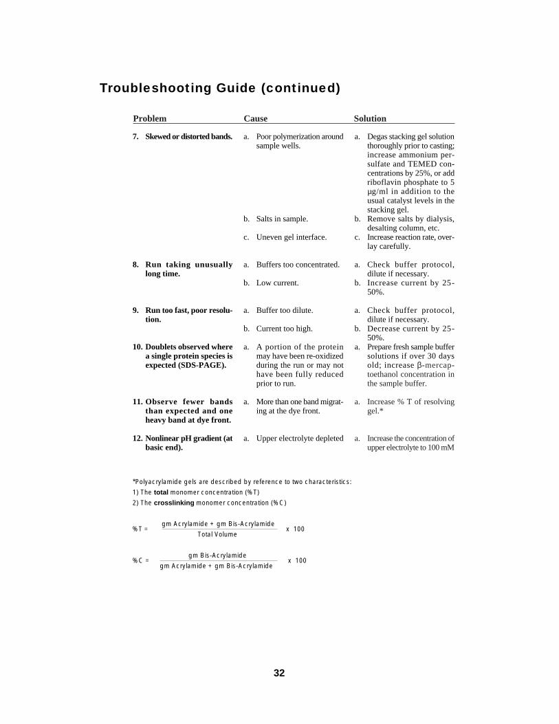
Troubleshooting Guide (continued)
*Polyacrylamide gels are described by reference to two characteristics:
1) The total monomer concentration (%T)
2) The crosslinking monomer concentration (%C)
%T =gm Acrylamide + gm Bis-Acrylamide
x 100Total Volume
%C = gm Bis-Acrylamide
x 100gm Acrylamide + gm Bis-Acrylamide
7. Skewed or distorted bands.
8. Run taking unusuallylong time.
9. Run too fast, poor resolu-tion.
10. Doublets observed wherea single protein species isexpected (SDS-PAGE).
11. Observe fewer bandsthan expected and oneheavy band at dye front.
12. Nonlinear pH gradient (atbasic end).
a. Poor polymerization aroundsample wells.
b. Salts in sample.
c. Uneven gel interface.
a. Buffers too concentrated.
b. Low current.
a. Buffer too dilute.
b. Current too high.
a. A portion of the proteinmay have been re-oxidizedduring the run or may nothave been fully reducedprior to run.
a. More than one band migrat-ing at the dye front.
a. Upper electrolyte depleted
a. Degas stacking gel solutionthoroughly prior to casting;increase ammonium per-sulfate and TEMED con-centrations by 25%, or addriboflavin phosphate to 5µg/ml in addition to theusual catalyst levels in thestacking gel.
b. Remove salts by dialysis,desalting column, etc.
c. Increase reaction rate, over-lay carefully.
a. Check buffer protocol,dilute if necessary.
b. Increase current by 25-50%.
a. Check buffer protocol,dilute if necessary.
b. Decrease current by 25-50%.
a. Prepare fresh sample buffersolutions if over 30 daysold; increase β-mercap-toethanol concentration inthe sample buffer.
a. Increase % T of resolvinggel.*
a. Increase the concentration ofupper electrolyte to 100 mM
Problem Cause Solution
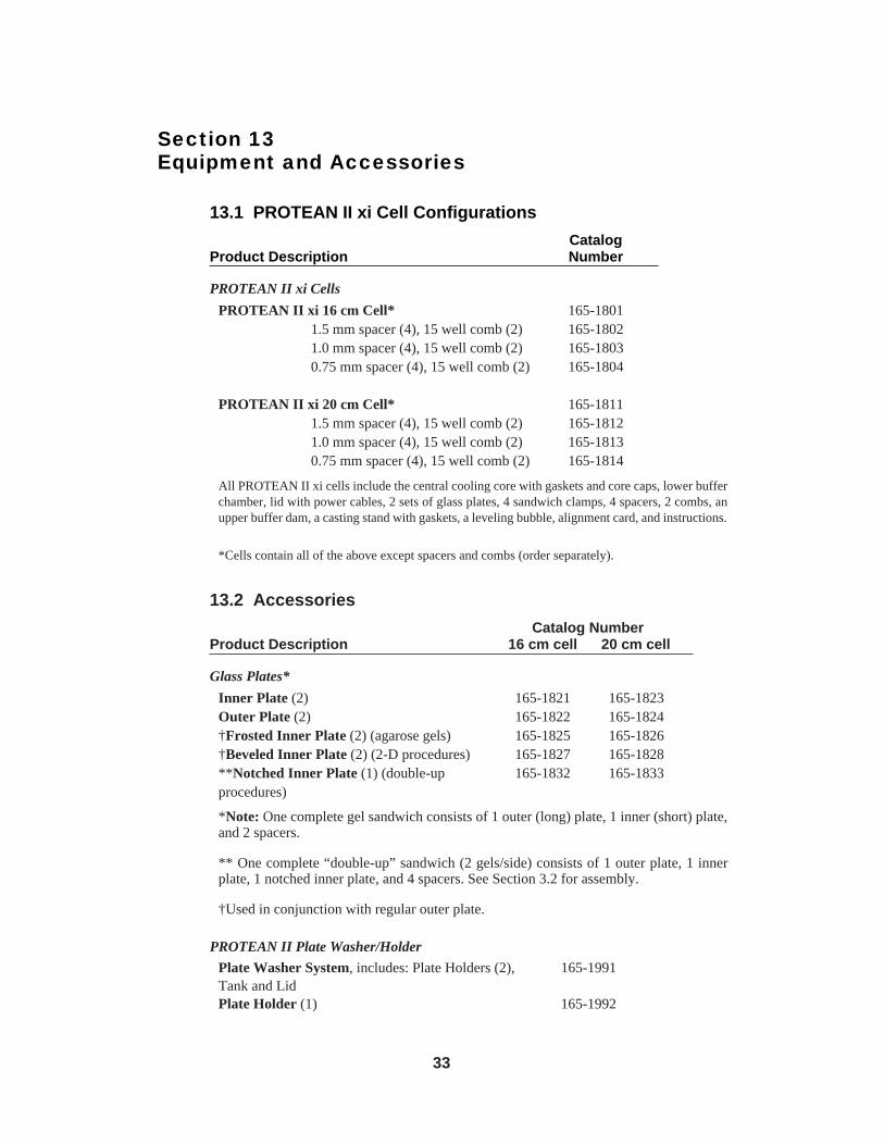
Section 13Equipment and Accessories
13.1 PROTEAN II xi Cell Configurations
CatalogProduct Description Number
PROTEAN II xi Cells
PROTEAN II xi 16 cm Cell* 165-18011.5 mm spacer (4), 15 well comb (2) 165-18021.0 mm spacer (4), 15 well comb (2) 165-18030.75 mm spacer (4), 15 well comb (2) 165-1804
PROTEAN II xi 20 cm Cell* 165-18111.5 mm spacer (4), 15 well comb (2) 165-18121.0 mm spacer (4), 15 well comb (2) 165-18130.75 mm spacer (4), 15 well comb (2) 165-1814
All PROTEAN II xi cells include the central cooling core with gaskets and core caps, lower bufferchamber, lid with power cables, 2 sets of glass plates, 4 sandwich clamps, 4 spacers, 2 combs, anupper buffer dam, a casting stand with gaskets, a leveling bubble, alignment card, and instructions.
*Cells contain all of the above except spacers and combs (order separately).
13.2 Accessories
Catalog NumberProduct Description 16 cm cell 20 cm cell
Glass Plates*
Inner Plate (2) 165-1821 165-1823Outer Plate (2) 165-1822 165-1824†Frosted Inner Plate (2) (agarose gels) 165-1825 165-1826†Beveled Inner Plate (2) (2-D procedures) 165-1827 165-1828**Notched Inner Plate (1) (double-up 165-1832 165-1833procedures)
*Note: One complete gel sandwich consists of 1 outer (long) plate, 1 inner (short) plate,and 2 spacers.
** One complete “double-up” sandwich (2 gels/side) consists of 1 outer plate, 1 innerplate, 1 notched inner plate, and 4 spacers. See Section 3.2 for assembly.
†Used in conjunction with regular outer plate.
PROTEAN II Plate Washer/Holder
Plate Washer System, includes: Plate Holders (2), 165-1991Tank and LidPlate Holder (1) 165-1992
33
34
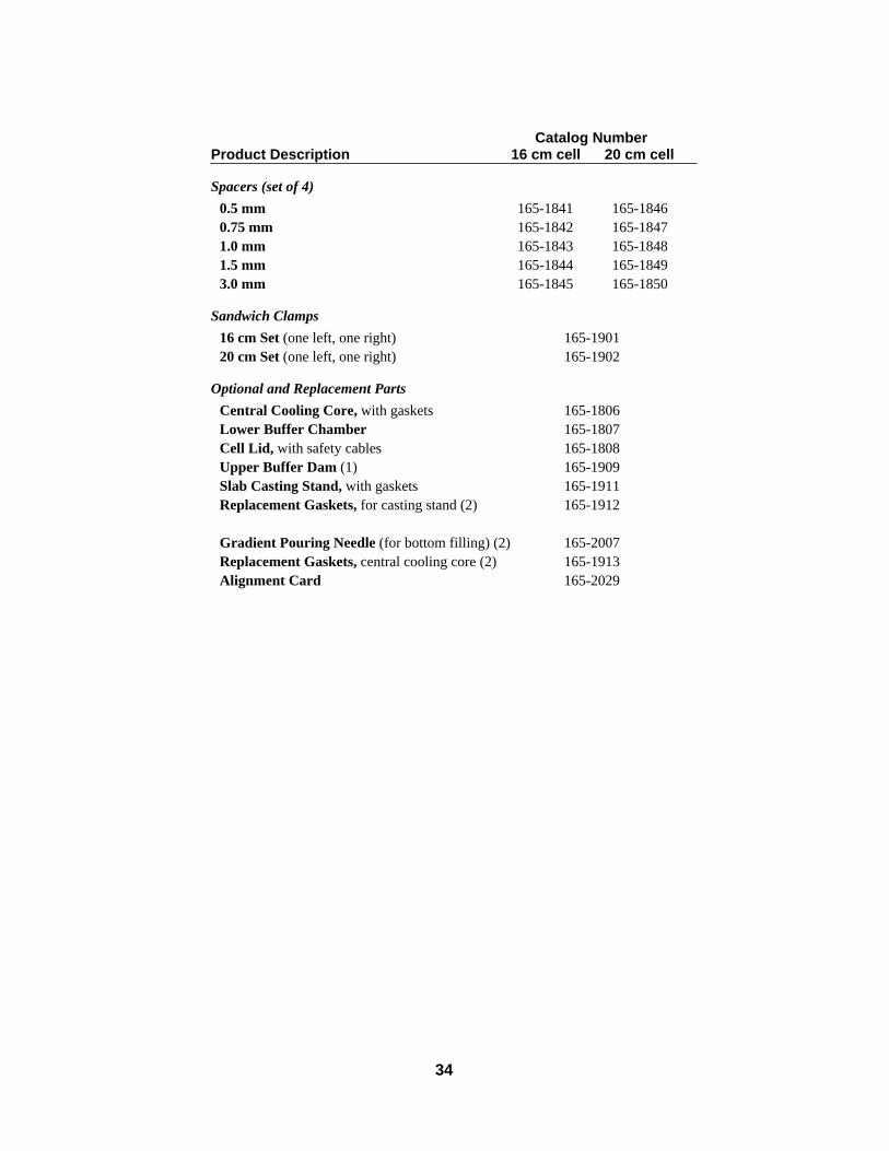
Catalog NumberProduct Description 16 cm cell 20 cm cell
Spacers (set of 4)
0.5 mm 165-1841 165-18460.75 mm 165-1842 165-18471.0 mm 165-1843 165-18481.5 mm 165-1844 165-18493.0 mm 165-1845 165-1850
Sandwich Clamps
16 cm Set (one left, one right) 165-190120 cm Set (one left, one right) 165-1902
Optional and Replacement Parts
Central Cooling Core, with gaskets 165-1806Lower Buffer Chamber 165-1807Cell Lid, with safety cables 165-1808Upper Buffer Dam (1) 165-1909Slab Casting Stand, with gaskets 165-1911Replacement Gaskets, for casting stand (2) 165-1912
Gradient Pouring Needle (for bottom filling) (2) 165-2007Replacement Gaskets, central cooling core (2) 165-1913Alignment Card 165-2029
35
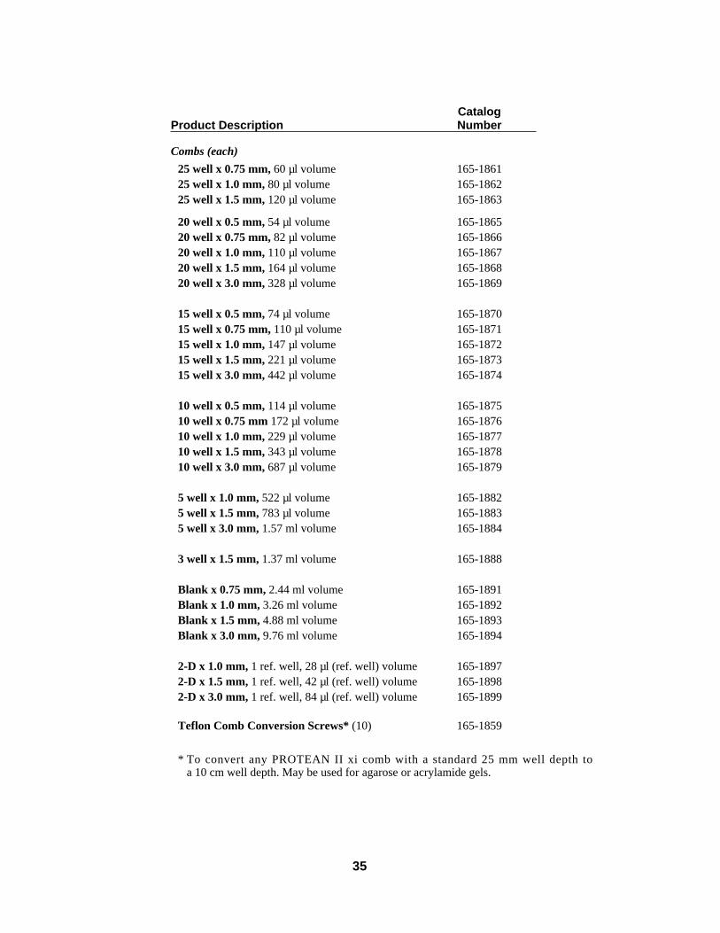
CatalogProduct Description Number
Combs (each)
25 well x 0.75 mm, 60 µl volume 165-186125 well x 1.0 mm, 80 µl volume 165-186225 well x 1.5 mm, 120 µl volume 165-1863
20 well x 0.5 mm, 54 µl volume 165-186520 well x 0.75 mm, 82 µl volume 165-186620 well x 1.0 mm, 110 µl volume 165-186720 well x 1.5 mm, 164 µl volume 165-186820 well x 3.0 mm, 328 µl volume 165-1869
15 well x 0.5 mm, 74 µl volume 165-187015 well x 0.75 mm, 110 µl volume 165-187115 well x 1.0 mm, 147 µl volume 165-187215 well x 1.5 mm, 221 µl volume 165-187315 well x 3.0 mm, 442 µl volume 165-1874
10 well x 0.5 mm, 114 µl volume 165-187510 well x 0.75 mm 172 µl volume 165-187610 well x 1.0 mm, 229 µl volume 165-187710 well x 1.5 mm, 343 µl volume 165-187810 well x 3.0 mm, 687 µl volume 165-1879
5 well x 1.0 mm, 522 µl volume 165-18825 well x 1.5 mm, 783 µl volume 165-18835 well x 3.0 mm, 1.57 ml volume 165-1884
3 well x 1.5 mm, 1.37 ml volume 165-1888
Blank x 0.75 mm, 2.44 ml volume 165-1891Blank x 1.0 mm, 3.26 ml volume 165-1892Blank x 1.5 mm, 4.88 ml volume 165-1893Blank x 3.0 mm, 9.76 ml volume 165-1894
2-D x 1.0 mm, 1 ref. well, 28 µl (ref. well) volume 165-18972-D x 1.5 mm, 1 ref. well, 42 µl (ref. well) volume 165-18982-D x 3.0 mm, 1 ref. well, 84 µl (ref. well) volume 165-1899
Teflon Comb Conversion Screws* (10) 165-1859
* To convert any PROTEAN II xi comb with a standard 25 mm well depth to a 10 cm well depth. May be used for agarose or acrylamide gels.
Glass TubesProduct Description
ID OD Length Pkg. Catalogmm mm mm Qty. Number1.0 5.0 180 24 165-31361.5 6.0 150 24 165-31371.5 6.0 180 24 165-31382.0 6.5 180 24 165-31392.4 4.0 160 24 165-31553.0 5.0 125 24 165-31505.0 7.0 125 24 165-3122
13.3 PROTEAN II xi 2-D CellsCatalog
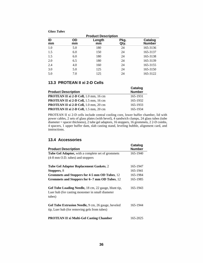
Product Description NumberPROTEAN II xi 2-D Cell, 1.0 mm, 16 cm 165-1931PROTEAN II xi 2-D Cell, 1.5 mm, 16 cm 165-1932PROTEAN II xi 2-D Cell, 1.0 mm, 20 cm 165-1933PROTEAN II xi 2-D Cell, 1.5 mm, 20 cm 165-1934
PROTEAN II xi 2-D cells include central cooling core, lower buffer chamber, lid withpower cables, 2 sets of glass plates (with bevel), 4 sandwich clamps, 24 glass tubes (tubediameter = spacer thickness), 2 tube gel adaptors, 16 stoppers, 16 grommets, 2 2-D combs,4 spacers, 1 upper buffer dam, slab casting stand, leveling bubble, alignment card, andinstructions.
13.4 AccessoriesCatalog
Product Description NumberTube Gel Adaptor, with a complete set of grommets 165-1940(4-8 mm O.D. tubes) and stoppers
Tube Gel Adaptor Replacement Gaskets, 2 165-1947Stoppers, 8 165-1941Grommets and Stoppers for 4-5 mm OD Tubes, 12 165-1984Grommets and Stoppers for 6–7 mm OD Tubes, 12 165-1985
Gel Tube Loading Needle, 18 cm, 22 gauge, blunt tip, 165-1943Luer hub (for casting monomer in small diametertubes)
Gel Tube Extrusion Needle, 9 cm, 26 gauge, beveled 165-1944tip, Luer hub (for removing gels from tubes)
PROTEAN II xi Multi-Gel Casting Chamber 165-2025
36
37
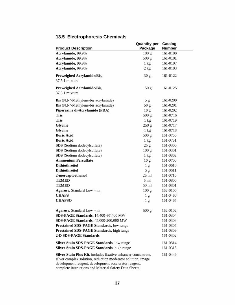
13.5 Electrophoresis ChemicalsQuantity per Catalog
Product Description Package NumberAcrylamide, 99.9% 100 g 161-0100Acrylamide, 99.9% 500 g 161-0101Acrylamide, 99.9% 1 kg 161-0107Acrylamide, 99.9% 2 kg 161-0103
Preweighed Acrylamide/Bis, 30 g 161-012237.5:1 mixture
Preweighed Acrylamide/Bis, 150 g 161-012537.5:1 mixture
Bis (N,N’-Methylene-bis acrylamide) 5 g 161-0200Bis (N,N’-Methylene-bis acrylamide) 50 g 161-0201Piperazine di-Acrylamide (PDA) 10 g 161-0202Tris 500 g 161-0716Tris 1 kg 161-0719Glycine 250 g 161-0717Glycine 1 kg 161-0718Boric Acid 500 g 161-0750Boric Acid 1 kg 161-0751SDS (Sodium dodecylsulfate) 25 g 161-0300SDS (Sodium dodecylsulfate) 100 g 161-0301SDS (Sodium dodecylsulfate) 1 kg 161-0302Ammonium Persulfate 10 g 161-0700Dithiothreitol 1 g 161-0610Dithiothreitol 5 g 161-06112-mercaptoethanol 25 ml 161-0710TEMED 5 ml 161-0800TEMED 50 ml 161-0801Agarose, Standard Low – mr 100 g 162-0100CHAPS 1 g 161-0460CHAPSO 1 g 161-0465
Agarose, Standard Low – mr 500 g 162-0102SDS-PAGE Standards, 14,400-97,400 MW 161-0304SDS-PAGE Standards, 45,000-200,000 MW 161-0303Prestained SDS-PAGE Standards, low range 161-0305Prestained SDS-PAGE Standards, high range 161-03092-D SDS-PAGE Standards 161-0302
Silver Stain SDS-PAGE Standards, low range 161-0314Silver Stain SDS-PAGE Standards, high range 161-0315
Silver Stain Plus Kit, includes fixative enhancer concentrate, 161-0449silver complex solution, reduction moderator solution, imagedevelopment reagent, development accelerator reagent,complete instructions and Material Safety Data Sheets
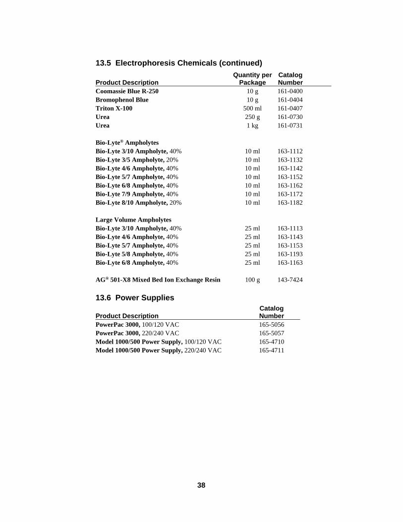
13.5 Electrophoresis Chemicals (continued)Quantity per Catalog
Product Description Package NumberCoomassie Blue R-250 10 g 161-0400Bromophenol Blue 10 g 161-0404Triton X-100 500 ml 161-0407Urea 250 g 161-0730Urea 1 kg 161-0731
Bio-Lyte® AmpholytesBio-Lyte 3/10 Ampholyte, 40% 10 ml 163-1112Bio-Lyte 3/5 Ampholyte, 20% 10 ml 163-1132Bio-Lyte 4/6 Ampholyte, 40% 10 ml 163-1142Bio-Lyte 5/7 Ampholyte, 40% 10 ml 163-1152Bio-Lyte 6/8 Ampholyte, 40% 10 ml 163-1162Bio-Lyte 7/9 Ampholyte, 40% 10 ml 163-1172Bio-Lyte 8/10 Ampholyte, 20% 10 ml 163-1182
Large Volume AmpholytesBio-Lyte 3/10 Ampholyte, 40% 25 ml 163-1113Bio-Lyte 4/6 Ampholyte, 40% 25 ml 163-1143Bio-Lyte 5/7 Ampholyte, 40% 25 ml 163-1153Bio-Lyte 5/8 Ampholyte, 40% 25 ml 163-1193Bio-Lyte 6/8 Ampholyte, 40% 25 ml 163-1163
AG® 501-X8 Mixed Bed Ion Exchange Resin 100 g 143-7424
13.6 Power SuppliesCatalog
Product Description NumberPowerPac 3000, 100/120 VAC 165-5056PowerPac 3000, 220/240 VAC 165-5057Model 1000/500 Power Supply, 100/120 VAC 165-4710Model 1000/500 Power Supply, 220/240 VAC 165-4711
38
39
Section 14Appendix
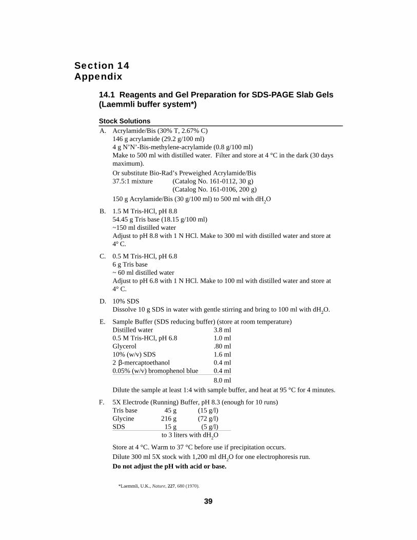
14.1 Reagents and Gel Preparation for SDS-PAGE Slab Gels(Laemmli buffer system*)
Stock SolutionsA. Acrylamide/Bis (30% T, 2.67% C)
146 g acrylamide (29.2 g/100 ml)4 g N’N’-Bis-methylene-acrylamide (0.8 g/100 ml)Make to 500 ml with distilled water. Filter and store at 4 °C in the dark (30 daysmaximum).
Or substitute Bio-Rad’s Preweighed Acrylamide/Bis37.5:1 mixture (Catalog No. 161-0112, 30 g)
(Catalog No. 161-0106, 200 g)
150 g Acrylamide/Bis (30 g/100 ml) to 500 ml with dH2O
B. 1.5 M Tris-HCl, pH 8.854.45 g Tris base (18.15 g/100 ml)~150 ml distilled waterAdjust to pH 8.8 with 1 N HCl. Make to 300 ml with distilled water and store at4° C.
C. 0.5 M Tris-HCl, pH 6.86 g Tris base~ 60 ml distilled waterAdjust to pH 6.8 with 1 N HCl. Make to 100 ml with distilled water and store at4° C.
D. 10% SDSDissolve 10 g SDS in water with gentle stirring and bring to 100 ml with dH2O.
E. Sample Buffer (SDS reducing buffer) (store at room temperature)Distilled water 3.8 ml0.5 M Tris-HCl, pH 6.8 1.0 mlGlycerol .80 ml10% (w/v) SDS 1.6 ml2 β-mercaptoethanol 0.4 ml0.05% (w/v) bromophenol blue 0.4 ml
8.0 ml
Dilute the sample at least 1:4 with sample buffer, and heat at 95 °C for 4 minutes.
F. 5X Electrode (Running) Buffer, pH 8.3 (enough for 10 runs)Tris base 45 g (15 g/l)Glycine 216 g (72 g/l)SDS 15 g (5 g/l)
to 3 liters with dH2O
Store at 4 °C. Warm to 37 °C before use if precipitation occurs.
Dilute 300 ml 5X stock with 1,200 ml dH2O for one electrophoresis run.
Do not adjust the pH with acid or base.
*Laemmli, U.K., Nature, 227, 680 (1970).
39
40
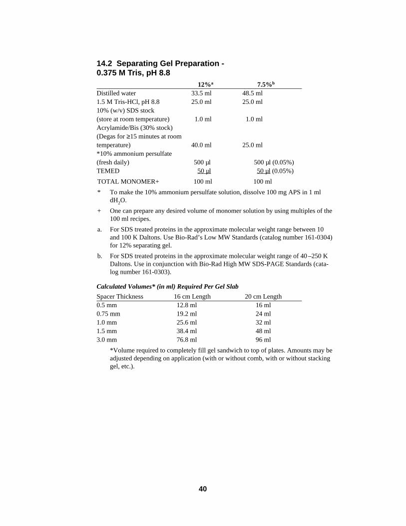
14.2 Separating Gel Preparation -0.375 M Tris, pH 8.8
12%a 7.5%b
Distilled water 33.5 ml 48.5 ml1.5 M Tris-HCl, pH 8.8 25.0 ml 25.0 ml10% (w/v) SDS stock(store at room temperature) 1.0 ml 1.0 mlAcrylamide/Bis (30% stock)(Degas for ≥15 minutes at roomtemperature) 40.0 ml 25.0 ml*10% ammonium persulfate(fresh daily) 500 µl 500 µl (0.05%)TEMED 50 µl 50 µl (0.05%)
TOTAL MONOMER+ 100 ml 100 ml
* To make the 10% ammonium persulfate solution, dissolve 100 mg APS in 1 mldH2O.
+ One can prepare any desired volume of monomer solution by using multiples of the100 ml recipes.
a. For SDS treated proteins in the approximate molecular weight range between 10and 100 K Daltons. Use Bio-Rad’s Low MW Standards (catalog number 161-0304)for 12% separating gel.
b. For SDS treated proteins in the approximate molecular weight range of 40 –250 KDaltons. Use in conjunction with Bio-Rad High MW SDS-PAGE Standards (cata-log number 161-0303).
Calculated Volumes* (in ml) Required Per Gel Slab
Spacer Thickness 16 cm Length 20 cm Length0.5 mm 12.8 ml 16 ml0.75 mm 19.2 ml 24 ml1.0 mm 25.6 ml 32 ml1.5 mm 38.4 ml 48 ml3.0 mm 76.8 ml 96 ml
*Volume required to completely fill gel sandwich to top of plates. Amounts may beadjusted depending on application (with or without comb, with or without stackinggel, etc.).
41
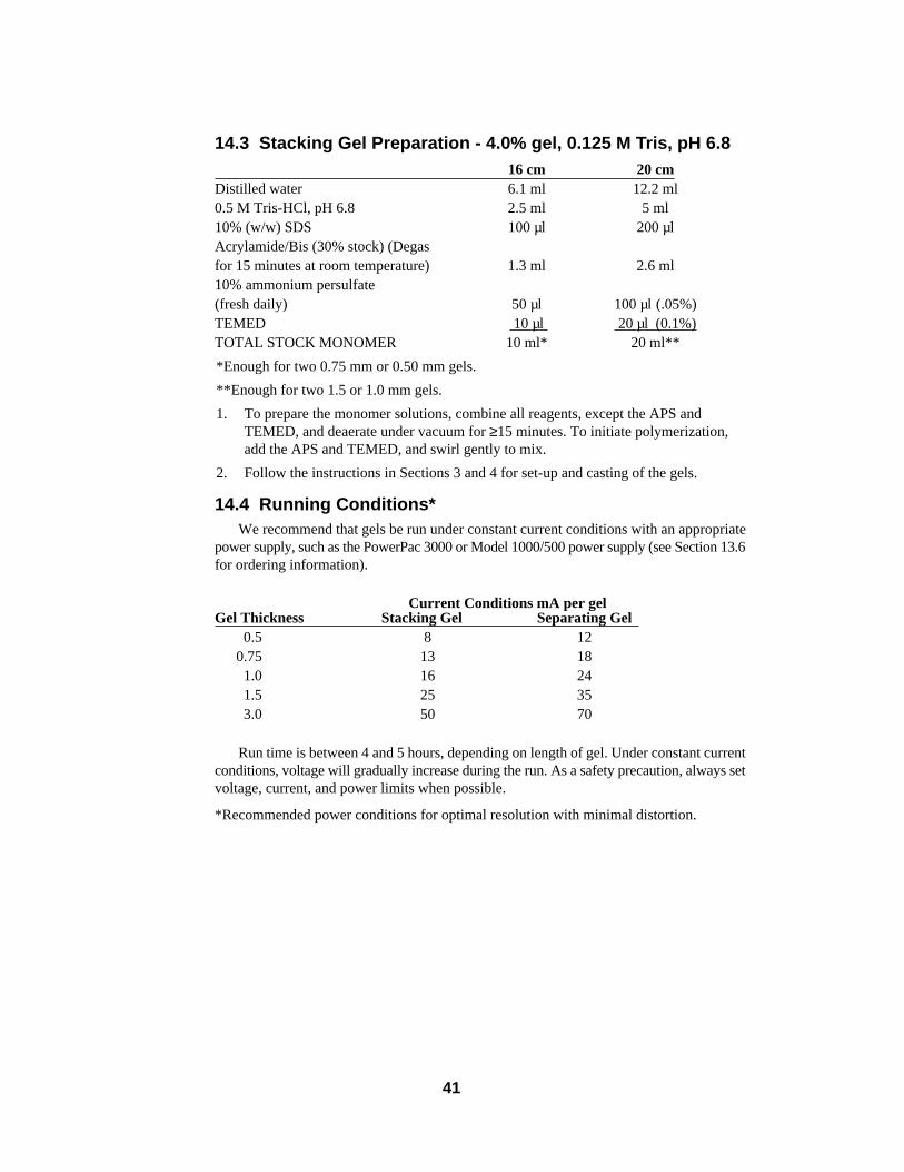
14.3 Stacking Gel Preparation - 4.0% gel, 0.125 M Tris, pH 6.816 cm 20 cm
Distilled water 6.1 ml 12.2 ml0.5 M Tris-HCl, pH 6.8 2.5 ml 5 ml10% (w/w) SDS 100 µl 200 µlAcrylamide/Bis (30% stock) (Degasfor 15 minutes at room temperature) 1.3 ml 2.6 ml10% ammonium persulfate(fresh daily) 50 µl 100 µl (.05%)TEMED 10 µl 20 µl (0.1%)TOTAL STOCK MONOMER 10 ml* 20 ml**
*Enough for two 0.75 mm or 0.50 mm gels.
**Enough for two 1.5 or 1.0 mm gels.
1. To prepare the monomer solutions, combine all reagents, except the APS andTEMED, and deaerate under vacuum for ≥15 minutes. To initiate polymerization,add the APS and TEMED, and swirl gently to mix.
2. Follow the instructions in Sections 3 and 4 for set-up and casting of the gels.
14.4 Running Conditions*We recommend that gels be run under constant current conditions with an appropriate
power supply, such as the PowerPac 3000 or Model 1000/500 power supply (see Section 13.6for ordering information).
Current Conditions mA per gelGel Thickness Stacking Gel Separating Gel
0.5 8 120.75 13 181.0 16 241.5 25 353.0 50 70
Run time is between 4 and 5 hours, depending on length of gel. Under constant currentconditions, voltage will gradually increase during the run. As a safety precaution, always setvoltage, current, and power limits when possible.
*Recommended power conditions for optimal resolution with minimal distortion.
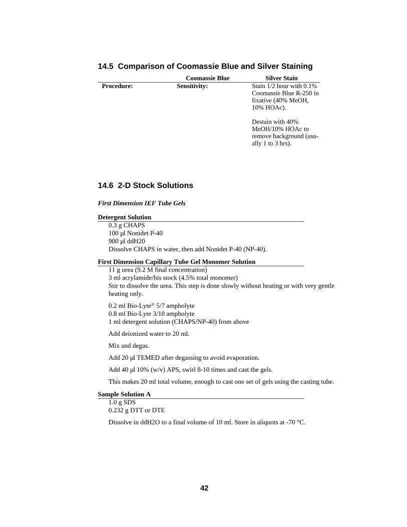
14.5 Comparison of Coomassie Blue and Silver StainingCoomassie Blue Silver Stain
14.6 2-D Stock Solutions
First Dimension IEF Tube Gels
Detergent Solution0.3 g CHAPS100 µl Nonidet P-40900 µl ddH20Dissolve CHAPS in water, then add Nonidet P-40 (NP-40).
First Dimension Capillary Tube Gel Monomer Solution11 g urea (9.2 M final concentration)3 ml acrylamide/bis stock (4.5% total monomer)Stir to dissolve the urea. This step is done slowly without heating or with very gentleheating only.
0.2 ml Bio-Lyte® 5/7 ampholyte0.8 ml Bio-Lyte 3/10 ampholyte1 ml detergent solution (CHAPS/NP-40) from above
Add deionized water to 20 ml.
Mix and degas.
Add 20 µl TEMED after degassing to avoid evaporation.
Add 40 µl 10% (w/v) APS, swirl 8-10 times and cast the gels.
This makes 20 ml total volume, enough to cast one set of gels using the casting tube.
Sample Solution A1.0 g SDS0.232 g DTT or DTE
Dissolve in ddH2O to a final volume of 10 ml. Store in aliquots at -70 °C.
Procedure: Sensitivity: Stain 1/2 hour with 0.1%Coomassie Blue R-250 infixative (40% MeOH,10% HOAc).
Destain with 40%MeOH/10% HOAc toremove background (usu-ally 1 to 3 hrs).
42
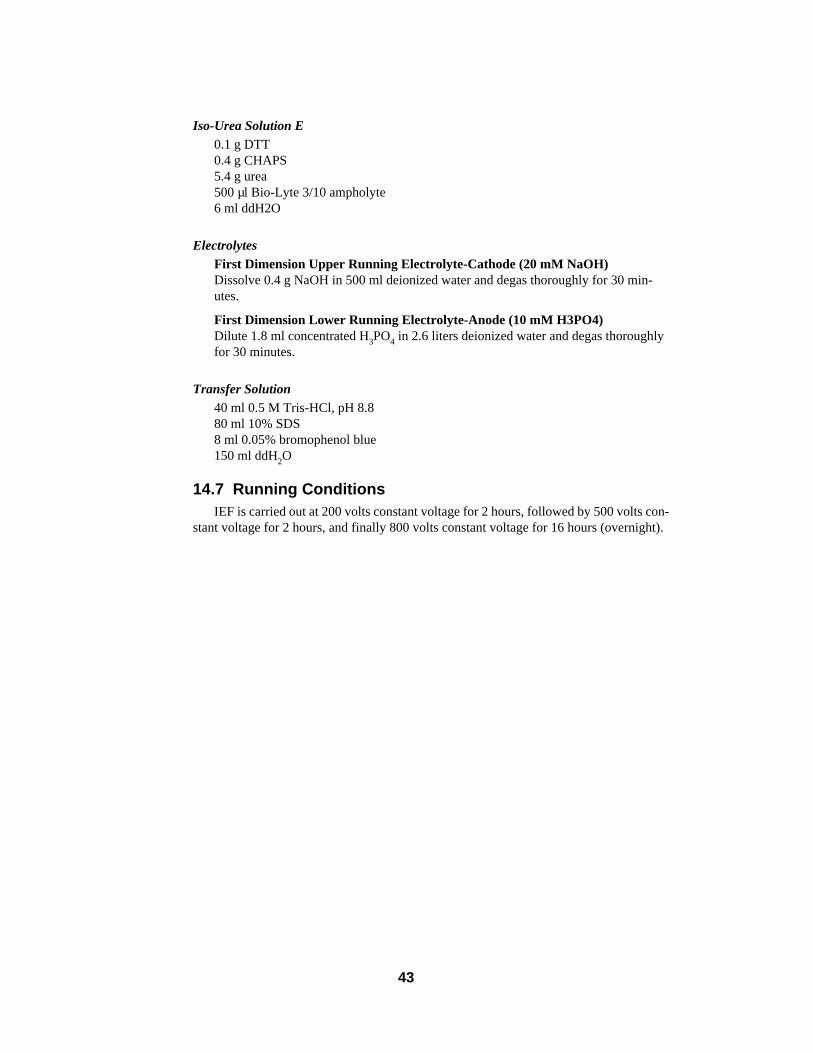
Iso-Urea Solution E0.1 g DTT0.4 g CHAPS5.4 g urea500 µl Bio-Lyte 3/10 ampholyte6 ml ddH2O
ElectrolytesFirst Dimension Upper Running Electrolyte-Cathode (20 mM NaOH)Dissolve 0.4 g NaOH in 500 ml deionized water and degas thoroughly for 30 min-utes.
First Dimension Lower Running Electrolyte-Anode (10 mM H3PO4)Dilute 1.8 ml concentrated H3PO4 in 2.6 liters deionized water and degas thoroughlyfor 30 minutes.
Transfer Solution40 ml 0.5 M Tris-HCl, pH 8.880 ml 10% SDS8 ml 0.05% bromophenol blue150 ml ddH2O
14.7 Running ConditionsIEF is carried out at 200 volts constant voltage for 2 hours, followed by 500 volts con-
stant voltage for 2 hours, and finally 800 volts constant voltage for 16 hours (overnight).
43
Section 15References
15.1 General References1. Gordon, A. H., “Laboratory Techniques in Biochemistry and Molecular Biology,” Vol. 1, Part 1
(Work, T. S. and Work, E., eds.), North Holland Publishing Co., Amsterdam-London (1975).
2. Maurer, H. R., “Disc Electrophoresis and Related Techniques of Polyacrylamide Gel Electrophoresis,”Walter de Gruyter, Berlin-New York (1971).
15.2 Native Gel Systems References1. Ritchie, R. F., Harter, J. G. and Bayles, T. B., J. Lab. Clin. Med., 68, 842 (1966).
2. Margolis, J. and Kendrick, K. G., Anal. Biochem., 25, 347 (1968).
3. Ornstein, L. and Davis, B. J., Ann. N.Y. Acad. Sci., 121, 321 (1964).
4. Reisfeld, R. A., Lewis, U. J. and William, D. E., Nature, 195, 281 (1962).
5. Blattler, D. P., Garner, F., Van Slyke, K. and Bradley, A., J. Chromatog., 64, 147 (1972).
6. Jeppesen, P. G. N., Anal. Biochem., 58, 195 (1974).
15.3 SDS Gel Systems References1. Shapiro, A. L., Vinuela, E. and Maizel, J. V., Biochem. Biophys. Res. Commun., 28, 815 (1967).
2. Laemmli, U. K., Nature, 227, 680 (1970).
3. Fairbanks, G., Steck, T. L. and Wallace, D. F. H., Biochemistry, 10, 2606 (1971).
4. Weber, K. and Osborn, M., J. Biol. Chem., 224, 4406 (1969).
5. Yamada, K. M. and Weston, J. A., Proc. Nat. Acad. Sci. U.S.A., 71, 3492 (1974).
6. Neville, D. M., J. Biol. Chem., 246, 6328 (1971).
7. O’Farrell, P. Z., Gold, L. M. and Huang, W. M., J. Biol. Chem., 248, 5499 (1973).
8. Studier, F. W., J. Mol. Biol., 79, 237 (1973).
9. Ferro-Luzzi Ames, G., J. Biol. Chem., 249, 634 (1974).
15.4 Urea Gel Systems References1. Kaltschmidt, E. and Wittmann, H. G., Anal. Biochem., 36, 401 (1970).
2. Swank, R. W. and Muckers, K. D., Anal. Biochem., 39, 462 (1971).
3. Jakes, K., Zinder, N. D. and Boon, T., J. Biol. Chem., 249, 438 (1974).
4. Mets, L. J. and Bogorad, L., Anal. Biochem., 57, 200 (1974).
5. Sherton, C. C. and Wool, I. G., J. Biol. Chem., 249, 2258 (1974).
15.5 Two-Dimensional IEF/SDS-PAGE Gel SystemsReferences
1. O’Farrell, P. H., J. Biol. Chem., 250, 4007 (1975).
2. Ferro-Luzzi Ames, G. and Nikaido, K., Biochem., 15, 616 (1976).
3. Anderson, L. and Anderson, N. G., Proc. Nat. Acad. Sci. U.S.A., 74, 5421 (1977).
4. O’Farrell, P. Z., Goodman, H. M. and O’Farrell, P. H., Cell, 12, 1133 (1977).
5. Garrels, J. I., J. Biol. Chem., 254, 7961 (1979).
6. Hochstrasser, D. F., Harrington, M. G., Hochstrasser, A. C., Miller, M.J. and Merril, C. R., AnalyticalBiochemistry, 173, 424-435 (1988).
7. Hochstrasser, D. F., Augsburger, V., Funk, M., Appel, R., Pelegrini, C. and Muller, A. F., Electrophoresis,7, 505-511 (1986).
44

Eastern Regional Office, 85A Marcus Dr., Melville, New York 11747 • Phone (516) 756-2575 • Fax (516) 756-2594European Headquarters, Bio-Rad Laboratories, Dreve du Sénéchal, 19, B-1180 Brussels • Phone 02 375 59 70 • Fax 02 374 61 62Australia, Bio-Rad Laboratories Pty Limited, Unit 11, 112-118 Talavera Rd P.O. Box 371, North Ryde, N.S.W. 2113 • Phone 02-805-5000 • Fax 02-805-1920Austria, Bio-Rad Laboratories Ges.m.b.H., Auhofstrasse 78D, A-1130 Wien • Phone 0222-877 89 01 • Fax 0222-876 56 29Belgium, Bio-Rad Laboratories S.A./N.V., Begoniastraat 5, B-9810 Nazareth Eke • Phone 091-85 55 11 • Fax 091-85 65 54Canada, Bio-Rad Laboratories (Canada) Ltd., 5149 Bradco Boulevard, Mississauga, Ontario L4W 2A6 • Phone (416) 624-0713 • Fax (416) 624-3019China, Bio-Rad Laboratories, Yanshan Hotel Office Tower, #1307, 138A Haidian Road, Beijing • Phone 2563146 • Fax 2564308France, Bio-Rad S.A., 94/96 rue Victor Hugo, B.P. 220, 94203 Ivry Sur Seine Cedex • Phone 01-49 60 68 34 • Fax 01-46 71 24 67Germany, Bio-Rad Laboratories GmbH, Heidemannstraße 164, Postfach 45 01 33, D-8000 München 45 • Phone 089-318 84-0 • Fax 089-318 84 100Italy, Bio-Rad Laboratories S.r.l.,Via Cellini, 18A, 20090 Segrate Milano • Phone 02-21609.1 • Fax 02-21609-399Japan, Nippon Bio-Rad Laboratories, K. K., Sumitomo Seimei Kachidoki Bldg 5-3-6 Kachidoki, Chuo-Ku, Tokyo 104 • Phone 03-3534-7515 • Fax 03-3534-8027The Netherlands, Bio-Rad Laboratories B. V., Fokkerstraat 10, 3905 KV Veenendaal • Phone 08385-40666 • Fax 08385-42216New Zealand, Bio-Rad Laboratories, Pty Ltd., P. O. Box 100-051, North Shore Mail Centre, Auckland 10 • Phone 09-443 3099 • Fax 09-443 3097Pacific, Bio-Rad Laboratories, Unit 1111, 11/F., New Kowloon Plaza, 38, Tai Kok Tsui Road, Tai Kok Tsui, Kowloon, Hong Kong • Phone 7893300 • Fax 7891257Scandinavia, Bio-Rad Laboratories, Kanalvägen 10C, 19461 Upplands Väsby, Sweden • Phone 46 (0) 8 590-73489 • Fax 46 (0) 8 590-71781Spain, Bio-Rad Laboratories, S. A. Avda Valdelaparra 3, Pol. Ind. Alcobendas, E-28100 Alcobendas, Madrid • Phone (91) 661 70 85 • Fax (91) 661 96 98Switzerland, Bio-Rad Laboratories AG, Kanalstrasse, 17, 8152 Glattbrugg • Phone 01-810 16 77 • Fax 01-810 19 33United Kingdom, Bio-Rad Laboratories Ltd., Bio-Rad House, Maylands Avenue, Hemel Hempstead, Herts HP2 7TD • Phone 0800 181134 • Fax 0442 259118
Life Science Group
2000 Alfred Nobel DriveHercules, California 94547Telephone (510) 741-1000Fax: (510) 741-1060
Printed in USA
M1651801 Rev B
Bio-Rad Laboratories