Embed Size (px)
Citation preview
© 3M 2018
1
6 7 1 11
Models
1 2 3 4 5 6 7 8 9 10
SM
MED
LG
XL
2X
L
3X
L
Pers
on
al S
RD
Lo
op
Do
rsal
Ste
rnal
Hip
Sh
ou
lder
Qu
ick C
on
nect
To
ng
ue B
uckle
Pass-T
hru
Belt
& H
ip P
ad
Sh
ou
lder
Pad
s
8 12
Size Attachment
Elements Buckles
Belt &
Pads
1161200 - 1161203
1
2
44
1161204 - 1161208
1
2
4 4
1161209 - 1161211
2
3
4 4
1
1161216 - 1161219
1
2
4 4
1161220 - 1161222
2
3
4 4
1161223 - 1161225
2
3
4 4
1161226 - 1161228
2
3
4 4
1161300 - 1161303
2
1161304 - 1161307
2
4 4
1161200 √ √ √ √ √ √ √
1161201 √ √ √ √ √ √ √ √
1161202 √ √ √ √ √ √ √
1161203 √ √ √ √ √ √ √
1161204 √ √ √ √ √ √ √
1161205 √ √ √ √ √ √ √ √
1161206 √ √ √ √ √ √ √ √
1161207 √ √ √ √ √ √ √
1161208 √ √ √ √ √ √ √
1161209 √ √ √ √ √ √ √ √
1161210 √ √ √ √ √ √ √ √ √
1161211 √ √ √ √ √ √ √ √
1161216 √ √ √ √ √ √ √ √
1161218 √ √ √ √ √ √ √ √
1161219 √ √ √ √ √ √ √ √
1161220 √ √ √ √ √ √ √
1161221 √ √ √ √ √ √ √ √
1161222 √ √ √ √ √ √ √
1161223 √ √ √ √ √ √ √ √
1161224 √ √ √ √ √ √ √ √ √
1161225 √ √ √ √ √ √ √ √
1161226 √ √ √ √ √ √ √ √
1161227 √ √ √ √ √ √ √ √ √
1161228 √ √ √ √ √ √ √ √
1161300 √ √ √ √
1161301 √ √ √ √ √
1161302 √ √ √ √
1161303 √ √ √ √
1161304 √ √ √ √ √ √
1161305 √ √ √ √ √ √ √
1161306 √ √ √ √ √ √
1161307 √ √ √ √ √ √
1161308 √ √ √ √ √ √
1161309 √ √ √ √ √ √ √
1161310 √ √ √ √ √ √
1161311 √ √ √ √ √ √
1161312 √ √ √ √ √ √
1161313 √ √ √ √ √ √ √
1161314 √ √ √ √ √ √
See back pages for additional models covered by this Instruction Manual. ...
USER INSTRUCTION MANUAL
PROTECTA PRO 3FULL BODY HARNESS
ANSI/ASSE Z359.11-2014
Form No: 5902327 Rev: K
1
6 7 1 11
Models
1 2 3 4 5 6 7 8 9 10
SM
MED
LG
XL
2X
L
3X
L
Pers
on
al S
RD
Lo
op
Do
rsal
Ste
rnal
Hip
Sh
ou
lder
Qu
ick C
on
nect
To
ng
ue B
uckle
Pass-T
hru
Belt
& H
ip P
ad
Sh
ou
lder
Pad
s
8 12
Size Attachment
Elements Buckles
Belt &
Pads
1161308 - 1161314
2
44
1161315 - 1161317
2
4 4
1161400 - 1161403
2
4 4
1161404 - 1161406
55
32
1161410 - 1161412
2
1161413 - 1161416
2
4 4
1161417 - 1161419
2
1161420 - 1161422
2
1161423 - 1161425
2
1161426 - 1161428
2
1161429 - 1161432
23
1161433 - 1161435
23
1161436 - 1161438
23
4 4
1161439 - 1161441
23
4 4
1161442 - 1161444
23
4 4
1161315 √ √ √ √ √ √ √
1161316 √ √ √ √ √ √ √ √
1161317 √ √ √ √ √ √ √
1161400 √ √ √ √ √
1161401 √ √ √ √ √ √
1161402 √ √ √ √ √
1161403 √ √ √ √ √
1161404 √ √ √ √ √ √
1161405 √ √ √ √ √ √ √
1161406 √ √ √ √ √ √
1161410 √ √◊ √ √
1161411 √ √ √◊ √ √
1161412 √ √◊ √ √
1161413 √ √ √ √ √
1161414 √ √ √ √ √ √
1161415 √ √ √ √ √
1161416 √ √ √ √ √
1161417 √ √ √ √
1161418 √ √ √ √ √
1161419 √ √ √ √
1161420 √ √ √ √ √
1161421 √ √ √ √ √ √
1161422 √ √ √ √ √
1161423 √ √ √ √
1161424 √ √ √ √ √
1161425 √ √ √ √
1161426 √ √ √ √
1161427 √ √ √ √ √
1161428 √ √ √ √
1161429 √ √ √ √ √
1161430 √ √ √ √ √ √
1161431 √ √ √ √ √
1161432 √ √ √ √ √
1161433 √ √ √ √ √
1161434 √ √ √ √ √ √
1161435 √ √ √ √ √
1161436 √ √ √ √ √ √
1161437 √ √ √ √ √ √ √
1161438 √ √ √ √ √ √
1161439 √ √ √ √ √ √ √
1161440 √ √ √ √ √ √ √ √
1161441 √ √ √ √ √ √ √
1161442 √ √ √ √ √ √
1161443 √ √ √ √ √ √ √
1161444 √ √ √ √ √ √
1161500 √ √ √
1161501 √ √ √ √
1161502 √ √ √ √ √
1161503 √ √ √ √
1161504 √ √ √ √
1161505 √ √ √
1161506 √ √ √ √ √
1161507 √ √ √ √ √ √
1161508 √ √ √ √ √
See back pages for additional models covered by this Instruction Manual. ...
1
6 7 1 11
Models
1 2 3 4 5 6 7 8 9 10
SM
MED
LG
XL
2X
L
3X
L
Pers
on
al S
RD
Lo
op
Do
rsal
Ste
rnal
Hip
Sh
ou
lder
Qu
ick C
on
nect
To
ng
ue B
uckle
Pass-T
hru
Belt
& H
ip P
ad
Sh
ou
lder
Pad
s
8 12
Size Attachment
Elements Buckles
Belt &
Pads
1161500 - 1161505
2
1161506 - 1161509
23
4
1161510 - 1161516
23
4 4
1161517 - 1161519
2 553
1161520 - 1161523
23
1161524 - 1161530
2
1161531 - 1161540
2
4 4
1161541 - 1161552
23
1161553 - 1161555
2
1161556 - 1161558
23
1161559 - 1161565
2
4 4
1161566 - 1161569
2
4 4
1161509 √ √ √ √ √
1161510 √ √ √ √ √
1161511 √ √ √ √ √ √
1161512 √ √ √ √ √
1161513 √ √ √ √ √
1161514 √ √ √ √ √ √
1161515 √ √ √ √ √
1161516 √ √ √ √ √
1161517 √ √ √ √ √
1161518 √ √ √ √ √ √
1161519 √ √ √ √ √
1161520 √ √ √ √
1161521 √ √ √ √ √
1161522 √ √ √ √
1161523 √ √ √ √
1161524 √ √ √
1161525 √ √ √ √
1161526 √ √ √
1161527 √ √ √
1161528 √ √ √
1161529 √ √ √ √
1161530 √ √ √
1161531 √ √ √ √
1161532 √ √ √ √ √
1161533 √ √ √ √
1161534 √ √ √ √
1161538 √ √ √ √
1161539 √ √ √ √ √
1161540 √ √ √ √
1161541 √ √ √
1161542 √ √ √ √
1161543 √ √ √
1161544 √ √ √
1161545 √ √ √
1161546 √ √ √
1161547 √ √ √ √
1161548 √ √ √
1161549 √ √ √
1161550 √ √ √ √
1161551 √ √ √
1161552 √ √ √
1161553 √ √ √ √
1161554 √ √ √ √ √
1161555 √ √ √ √
1161556 √ √ √ √
1161557 √ √ √ √ √
1161558 √ √ √ √
1161559 √ √ √ √
1161560 √ √ √ √ √
1161561 √ √ √ √
1161562 √ √ √ √
1161563 √ √ √ √
1161564 √ √ √ √ √
1161565 √ √ √ √
1161566 √ √ √ √
1161567 √ √ √ √ √
See back pages for additional models covered by this Instruction Manual. ...
1
6 7 1 11
Models
1 2 3 4 5 6 7 8 9 10
SM
MED
LG
XL
2X
L
3X
L
Pers
on
al S
RD
Lo
op
Do
rsal
Ste
rnal
Hip
Sh
ou
lder
Qu
ick C
on
nect
To
ng
ue B
uckle
Pass-T
hru
Belt
& H
ip P
ad
Sh
ou
lder
Pad
s
8 12
Size Attachment
Elements Buckles
Belt &
Pads
1161570 - 1161579
2
1161568 √ √ √ √
1161569 √ √ √ √
1161570 √ √ √
1161571 √ √ √ √
1161572 √ √ √
1161573 √ √ √
1161576 √ √ √
1161577 √ √ √ √
1161578 √ √ √
1161579 √ √ √
5
2
A B C D E F
3 4
C
B
A
FC
B
C
FC
5 6
A B C
7
A B C
6
8
A
B
C
D
9
1
A
CLICK!
B
C
2
3
A
B
7
10
A B
11
A B
C D
8
12
1 2 3
4 5 6
9
13
A
A
A
A
FORM NO: 5908245 REV: A 10
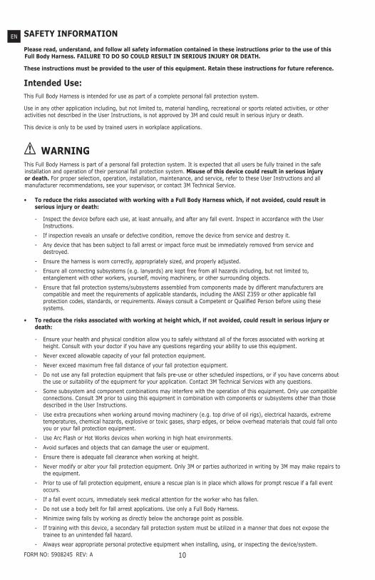
SAFETY INFORMATION
Please read, understand, and follow all safety information contained in these instructions prior to the use of this Full Body Harness. FAILURE TO DO SO COULD RESULT IN SERIOUS INJURY OR DEATH.
These instructions must be provided to the user of this equipment. Retain these instructions for future reference.
Intended Use:This Full Body Harness is intended for use as part of a complete personal fall protection system.
Use in any other application including, but not limited to, material handling, recreational or sports related activities, or other activities not described in the User Instructions, is not approved by 3M and could result in serious injury or death.
This device is only to be used by trained users in workplace applications.
! WARNINGThis Full Body Harness is part of a personal fall protection system. It is expected that all users be fully trained in the safe installation and operation of their personal fall protection system. Misuse of this device could result in serious injury or death. For proper selection, operation, installation, maintenance, and service, refer to these User Instructions and all manufacturer recommendations, see your supervisor, or contact 3M Technical Service.
• To reduce the risks associated with working with a Full Body Harness which, if not avoided, could result in serious injury or death:
- Inspect the device before each use, at least annually, and after any fall event. Inspect in accordance with the User Instructions.
- If inspection reveals an unsafe or defective condition, remove the device from service and destroy it.
- Any device that has been subject to fall arrest or impact force must be immediately removed from service and destroyed.
- Ensure the harness is worn correctly, appropriately sized, and properly adjusted.
- Ensure all connecting subsystems (e.g. lanyards) are kept free from all hazards including, but not limited to, entanglement with other workers, yourself, moving machinery, or other surrounding objects.
- Ensure that fall protection systems/subsystems assembled from components made by different manufacturers are compatible and meet the requirements of applicable standards, including the ANSI Z359 or other applicable fall protection codes, standards, or requirements. Always consult a Competent or Qualifi ed Person before using these systems.
• To reduce the risks associated with working at height which, if not avoided, could result in serious injury or death:
- Ensure your health and physical condition allow you to safely withstand all of the forces associated with working at height. Consult with your doctor if you have any questions regarding your ability to use this equipment.
- Never exceed allowable capacity of your fall protection equipment.
- Never exceed maximum free fall distance of your fall protection equipment.
- Do not use any fall protection equipment that fails pre-use or other scheduled inspections, or if you have concerns about the use or suitability of the equipment for your application. Contact 3M Technical Services with any questions.
- Some subsystem and component combinations may interfere with the operation of this equipment. Only use compatible connections. Consult 3M prior to using this equipment in combination with components or subsystems other than those described in the User Instructions.
- Use extra precautions when working around moving machinery (e.g. top drive of oil rigs), electrical hazards, extreme temperatures, chemical hazards, explosive or toxic gases, sharp edges, or below overhead materials that could fall onto you or your fall protection equipment.
- Use Arc Flash or Hot Works devices when working in high heat environments.
- Avoid surfaces and objects that can damage the user or equipment.
- Ensure there is adequate fall clearance when working at height.
- Never modify or alter your fall protection equipment. Only 3M or parties authorized in writing by 3M may make repairs to the equipment.
- Prior to use of fall protection equipment, ensure a rescue plan is in place which allows for prompt rescue if a fall event occurs.
- If a fall event occurs, immediately seek medical attention for the worker who has fallen.
- Do not use a body belt for fall arrest applications. Use only a Full Body Harness.
- Minimize swing falls by working as directly below the anchorage point as possible.
- If training with this device, a secondary fall protection system must be utilized in a manner that does not expose the trainee to an unintended fall hazard.
- Always wear appropriate personal protective equipment when installing, using, or inspecting the device/system.
EN
11
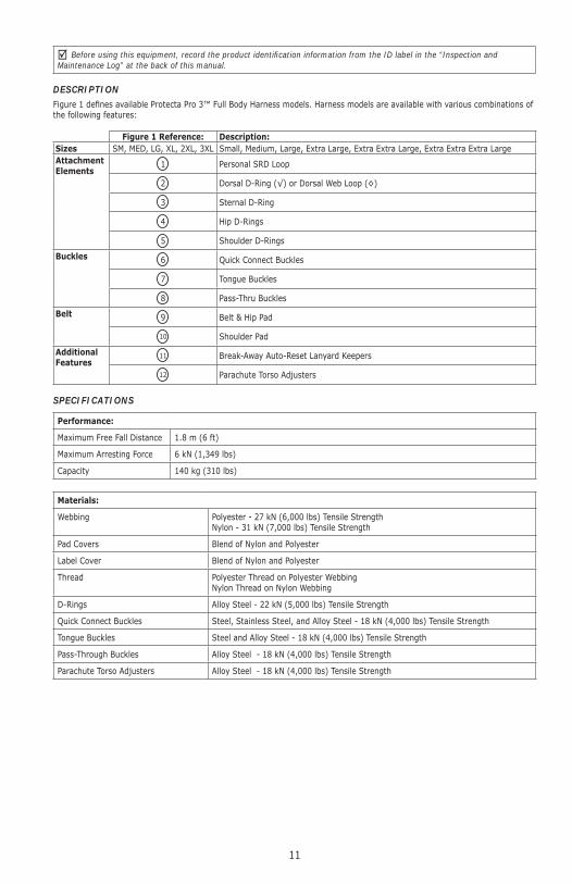
Before using this equipment, record the product identifi cation information from the ID label in the “Inspection and Maintenance Log” at the back of this manual.
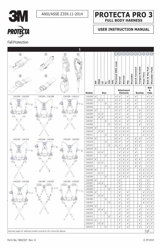
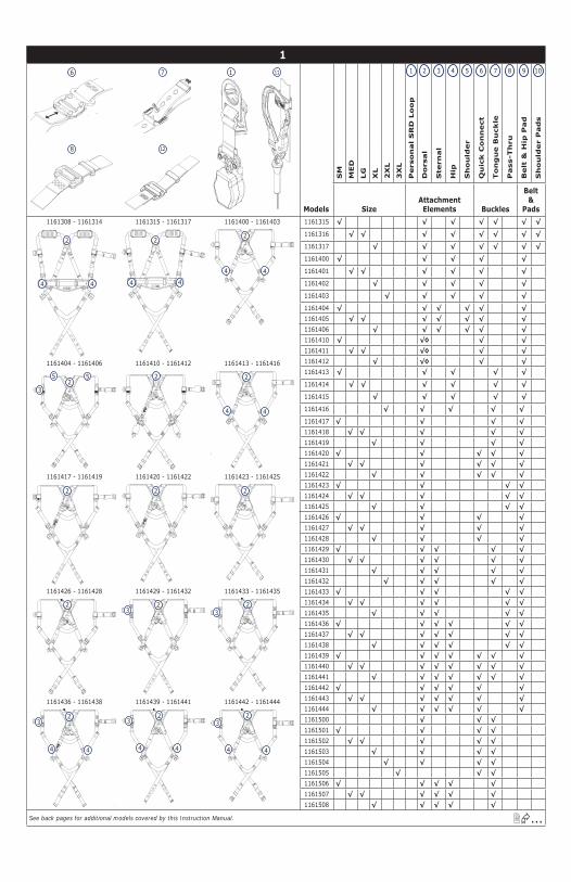
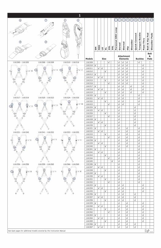
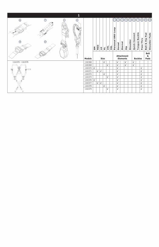
DESCRIPTIONFigure 1 defi nes available Protecta Pro 3™ Full Body Harness models. Harness models are available with various combinations of the following features:
Figure 1 Reference: Description:Sizes SM, MED, LG, XL, 2XL, 3XL Small, Medium, Large, Extra Large, Extra Extra Large, Extra Extra Extra Large Attachment Elements 1 Personal SRD Loop
2 Dorsal D-Ring (√) or Dorsal Web Loop (◊)
3 Sternal D-Ring
4 Hip D-Rings
5 Shoulder D-Rings
Buckles 6 Quick Connect Buckles
7 Tongue Buckles
8 Pass-Thru Buckles
Belt 9 Belt & Hip Pad
10 Shoulder Pad
Additional Features
11 Break-Away Auto-Reset Lanyard Keepers
12 Parachute Torso Adjusters
SPECIFICATIONS
Performance:
Maximum Free Fall Distance 1.8 m (6 ft)
Maximum Arresting Force 6 kN (1,349 lbs)
Capacity 140 kg (310 lbs)
Materials:
Webbing Polyester - 27 kN (6,000 lbs) Tensile StrengthNylon - 31 kN (7,000 lbs) Tensile Strength
Pad Covers Blend of Nylon and Polyester
Label Cover Blend of Nylon and Polyester
Thread Polyester Thread on Polyester WebbingNylon Thread on Nylon Webbing
D-Rings Alloy Steel - 22 kN (5,000 lbs) Tensile Strength
Quick Connect Buckles Steel, Stainless Steel, and Alloy Steel - 18 kN (4,000 lbs) Tensile Strength
Tongue Buckles Steel and Alloy Steel - 18 kN (4,000 lbs) Tensile Strength
Pass-Through Buckles Alloy Steel - 18 kN (4,000 lbs) Tensile Strength
Parachute Torso Adjusters Alloy Steel - 18 kN (4,000 lbs) Tensile Strength
12
1.0 APPLICATIONS
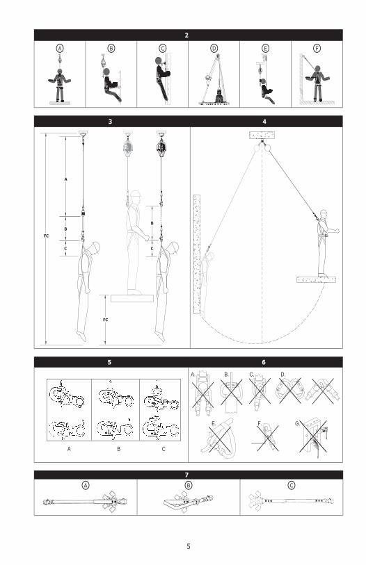
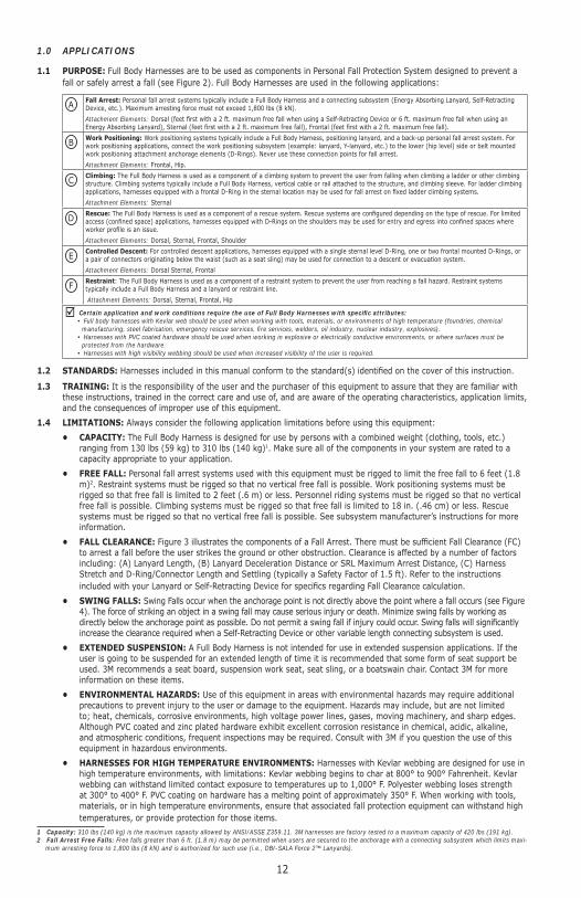
1.1 PURPOSE: Full Body Harnesses are to be used as components in Personal Fall Protection System designed to prevent a fall or safely arrest a fall (see Figure 2). Full Body Harnesses are used in the following applications:
AFall Arrest: Personal fall arrest systems typically include a Full Body Harness and a connecting subsystem (Energy Absorbing Lanyard, Self-Retracting Device, etc.). Maximum arresting force must not exceed 1,800 lbs (8 kN).
Attachment Elements: Dorsal (feet fi rst with a 2 ft. maximum free fall when using a Self-Retracting Device or 6 ft. maximum free fall when using an Energy Absorbing Lanyard), Sternal (feet fi rst with a 2 ft. maximum free fall), Frontal (feet fi rst with a 2 ft. maximum free fall).
BWork Positioning: Work positioning systems typically include a Full Body Harness, positioning lanyard, and a back-up personal fall arrest system. For work positioning applications, connect the work positioning subsystem (example: lanyard, Y-lanyard, etc.) to the lower (hip level) side or belt mounted work positioning attachment anchorage elements (D-Rings). Never use these connection points for fall arrest.
Attachment Elements: Frontal, Hip.
CClimbing: The Full Body Harness is used as a component of a climbing system to prevent the user from falling when climbing a ladder or other climbing structure. Climbing systems typically include a Full Body Harness, vertical cable or rail attached to the structure, and climbing sleeve. For ladder climbing applications, harnesses equipped with a frontal D-Ring in the sternal location may be used for fall arrest on fi xed ladder climbing systems.
Attachment Elements: Sternal
DRescue: The Full Body Harness is used as a component of a rescue system. Rescue systems are confi gured depending on the type of rescue. For limited access (confi ned space) applications, harnesses equipped with D-Rings on the shoulders may be used for entry and egress into confi ned spaces where worker profi le is an issue.
Attachment Elements: Dorsal, Sternal, Frontal, Shoulder
EControlled Descent: For controlled descent applications, harnesses equipped with a single sternal level D-Ring, one or two frontal mounted D-Rings, or a pair of connectors originating below the waist (such as a seat sling) may be used for connection to a descent or evacuation system.
Attachment Elements: Dorsal Sternal, Frontal
FRestraint: The Full Body Harness is used as a component of a restraint system to prevent the user from reaching a fall hazard. Restraint systems typically include a Full Body Harness and a lanyard or restraint line.
Attachment Elements: Dorsal, Sternal, Frontal, Hip
Certain application and work conditions require the use of Full Body Harnesses with specifi c attributes:• Full body harnesses with Kevlar web should be used when working with tools, materials, or environments of high temperature (foundries, chemical
manufacturing, steel fabrication, emergency rescue services, fi re services, welders, oil industry, nuclear industry, explosives).• Harnesses with PVC coated hardware should be used when working in explosive or electrically conductive environments, or where surfaces must be
protected from the hardware.• Harnesses with high visibility webbing should be used when increased visibility of the user is required.
1.2 STANDARDS: Harnesses included in this manual conform to the standard(s) identifi ed on the cover of this instruction.
1.3 TRAINING: It is the responsibility of the user and the purchaser of this equipment to assure that they are familiar with these instructions, trained in the correct care and use of, and are aware of the operating characteristics, application limits, and the consequences of improper use of this equipment.
1.4 LIMITATIONS: Always consider the following application limitations before using this equipment:
• CAPACITY: The Full Body Harness is designed for use by persons with a combined weight (clothing, tools, etc.) ranging from 130 lbs (59 kg) to 310 lbs (140 kg)1. Make sure all of the components in your system are rated to a capacity appropriate to your application.
• FREE FALL: Personal fall arrest systems used with this equipment must be rigged to limit the free fall to 6 feet (1.8 m)2. Restraint systems must be rigged so that no vertical free fall is possible. Work positioning systems must be rigged so that free fall is limited to 2 feet (.6 m) or less. Personnel riding systems must be rigged so that no vertical free fall is possible. Climbing systems must be rigged so that free fall is limited to 18 in. (.46 cm) or less. Rescue systems must be rigged so that no vertical free fall is possible. See subsystem manufacturer’s instructions for more information.
• FALL CLEARANCE: Figure 3 illustrates the components of a Fall Arrest. There must be suffi cient Fall Clearance (FC) to arrest a fall before the user strikes the ground or other obstruction. Clearance is affected by a number of factors including: (A) Lanyard Length, (B) Lanyard Deceleration Distance or SRL Maximum Arrest Distance, (C) Harness Stretch and D-Ring/Connector Length and Settling (typically a Safety Factor of 1.5 ft). Refer to the instructions included with your Lanyard or Self-Retracting Device for specifi cs regarding Fall Clearance calculation.
• SWING FALLS: Swing Falls occur when the anchorage point is not directly above the point where a fall occurs (see Figure 4). The force of striking an object in a swing fall may cause serious injury or death. Minimize swing falls by working as directly below the anchorage point as possible. Do not permit a swing fall if injury could occur. Swing falls will signifi cantly increase the clearance required when a Self-Retracting Device or other variable length connecting subsystem is used.
• EXTENDED SUSPENSION: A Full Body Harness is not intended for use in extended suspension applications. If the user is going to be suspended for an extended length of time it is recommended that some form of seat support be used. 3M recommends a seat board, suspension work seat, seat sling, or a boatswain chair. Contact 3M for more information on these items.
• ENVIRONMENTAL HAZARDS: Use of this equipment in areas with environmental hazards may require additional precautions to prevent injury to the user or damage to the equipment. Hazards may include, but are not limited to; heat, chemicals, corrosive environments, high voltage power lines, gases, moving machinery, and sharp edges. Although PVC coated and zinc plated hardware exhibit excellent corrosion resistance in chemical, acidic, alkaline, and atmospheric conditions, frequent inspections may be required. Consult with 3M if you question the use of this equipment in hazardous environments.
• HARNESSES FOR HIGH TEMPERATURE ENVIRONMENTS: Harnesses with Kevlar webbing are designed for use in high temperature environments, with limitations: Kevlar webbing begins to char at 800° to 900° Fahrenheit. Kevlar webbing can withstand limited contact exposure to temperatures up to 1,000° F. Polyester webbing loses strength at 300° to 400° F. PVC coating on hardware has a melting point of approximately 350° F. When working with tools, materials, or in high temperature environments, ensure that associated fall protection equipment can withstand high temperatures, or provide protection for those items.
1 Capacity: 310 lbs (140 kg) is the maximum capacity allowed by ANSI/ASSE Z359.11. 3M harnesses are factory tested to a maximum capacity of 420 lbs (191 kg).2 Fall Arrest Free Falls: Free falls greater than 6 ft. (1.8 m) may be permitted when users are secured to the anchorage with a connecting subsystem which limits maxi-
mum arresting force to 1,800 lbs (8 kN) and is authorized for such use (i.e., DBI-SALA Force 2™ Lanyards).
13
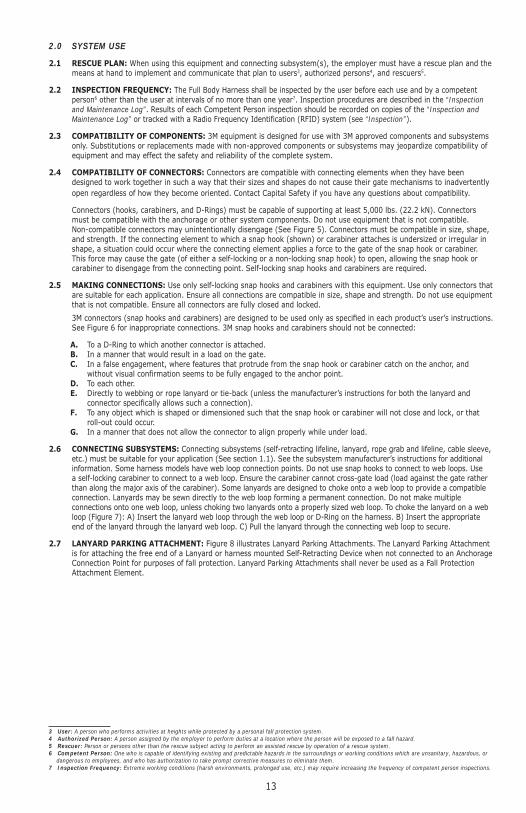
2.0 SYSTEM USE
2.1 RESCUE PLAN: When using this equipment and connecting subsystem(s), the employer must have a rescue plan and the means at hand to implement and communicate that plan to users3, authorized persons4, and rescuers5.
2.2 INSPECTION FREQUENCY: The Full Body Harness shall be inspected by the user before each use and by a competent person6 other than the user at intervals of no more than one year7. Inspection procedures are described in the “Inspection and Maintenance Log”. Results of each Competent Person inspection should be recorded on copies of the “Inspection and Maintenance Log” or tracked with a Radio Frequency Identification (RFID) system (see “Inspection”).
2.3 COMPATIBILITY OF COMPONENTS: 3M equipment is designed for use with 3M approved components and subsystems only. Substitutions or replacements made with non-approved components or subsystems may jeopardize compatibility of equipment and may effect the safety and reliability of the complete system.
2.4 COMPATIBILITY OF CONNECTORS: Connectors are compatible with connecting elements when they have been designed to work together in such a way that their sizes and shapes do not cause their gate mechanisms to inadvertently open regardless of how they become oriented. Contact Capital Safety if you have any questions about compatibility.
Connectors (hooks, carabiners, and D-Rings) must be capable of supporting at least 5,000 lbs. (22.2 kN). Connectors must be compatible with the anchorage or other system components. Do not use equipment that is not compatible. Non-compatible connectors may unintentionally disengage (See Figure 5). Connectors must be compatible in size, shape, and strength. If the connecting element to which a snap hook (shown) or carabiner attaches is undersized or irregular in shape, a situation could occur where the connecting element applies a force to the gate of the snap hook or carabiner. This force may cause the gate (of either a self-locking or a non-locking snap hook) to open, allowing the snap hook or carabiner to disengage from the connecting point. Self-locking snap hooks and carabiners are required.
2.5 MAKING CONNECTIONS: Use only self-locking snap hooks and carabiners with this equipment. Use only connectors that are suitable for each application. Ensure all connections are compatible in size, shape and strength. Do not use equipment that is not compatible. Ensure all connectors are fully closed and locked.
3M connectors (snap hooks and carabiners) are designed to be used only as specifi ed in each product’s user’s instructions. See Figure 6 for inappropriate connections. 3M snap hooks and carabiners should not be connected:
A. To a D-Ring to which another connector is attached.B. In a manner that would result in a load on the gate.C. In a false engagement, where features that protrude from the snap hook or carabiner catch on the anchor, and
without visual confirmation seems to be fully engaged to the anchor point.D. To each other.E. Directly to webbing or rope lanyard or tie-back (unless the manufacturer’s instructions for both the lanyard and
connector specifically allows such a connection).F. To any object which is shaped or dimensioned such that the snap hook or carabiner will not close and lock, or that
roll-out could occur.G. In a manner that does not allow the connector to align properly while under load.
2.6 CONNECTING SUBSYSTEMS: Connecting subsystems (self-retracting lifeline, lanyard, rope grab and lifeline, cable sleeve, etc.) must be suitable for your application (See section 1.1). See the subsystem manufacturer’s instructions for additional information. Some harness models have web loop connection points. Do not use snap hooks to connect to web loops. Use a self-locking carabiner to connect to a web loop. Ensure the carabiner cannot cross-gate load (load against the gate rather than along the major axis of the carabiner). Some lanyards are designed to choke onto a web loop to provide a compatible connection. Lanyards may be sewn directly to the web loop forming a permanent connection. Do not make multiple connections onto one web loop, unless choking two lanyards onto a properly sized web loop. To choke the lanyard on a web loop (Figure 7): A) Insert the lanyard web loop through the web loop or D-Ring on the harness. B) Insert the appropriate end of the lanyard through the lanyard web loop. C) Pull the lanyard through the connecting web loop to secure.
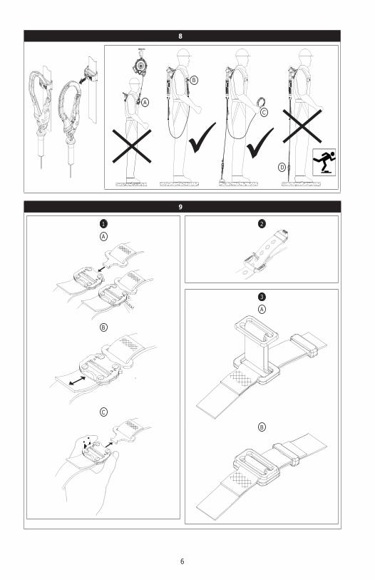
2.7 LANYARD PARKING ATTACHMENT: Figure 8 illustrates Lanyard Parking Attachments. The Lanyard Parking Attachment is for attaching the free end of a Lanyard or harness mounted Self-Retracting Device when not connected to an Anchorage Connection Point for purposes of fall protection. Lanyard Parking Attachments shall never be used as a Fall Protection Attachment Element.
3 User: A person who performs activities at heights while protected by a personal fall protection system.4 Authorized Person: A person assigned by the employer to perform duties at a location where the person will be exposed to a fall hazard.5 Rescuer: Person or persons other than the rescue subject acting to perform an assisted rescue by operation of a rescue system.6 Competent Person: One who is capable of identifying existing and predictable hazards in the surroundings or working conditions which are unsanitary, hazardous, or
dangerous to employees, and who has authorization to take prompt corrective measures to eliminate them.7 Inspection Frequency: Extreme working conditions (harsh environments, prolonged use, etc.) may require increasing the frequency of competent person inspections.
14
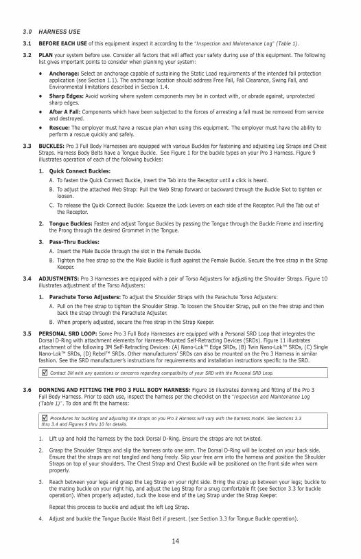
3.0 HARNESS USE
3.1 BEFORE EACH USE of this equipment inspect it according to the “Inspection and Maintenance Log” (Table 1).
3.2 PLAN your system before use. Consider all factors that will affect your safety during use of this equipment. The following list gives important points to consider when planning your system:
• Anchorage: Select an anchorage capable of sustaining the Static Load requirements of the intended fall protection application (see Section 1.1). The anchorage location should address Free Fall, Fall Clearance, Swing Fall, and Environmental limitations described in Section 1.4.
• Sharp Edges: Avoid working where system components may be in contact with, or abrade against, unprotected sharp edges.
• After A Fall: Components which have been subjected to the forces of arresting a fall must be removed from service and destroyed.
• Rescue: The employer must have a rescue plan when using this equipment. The employer must have the ability to perform a rescue quickly and safely.
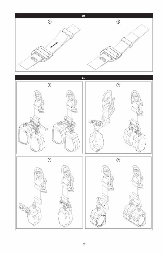
3.3 BUCKLES: Pro 3 Full Body Harnesses are equipped with various Buckles for fastening and adjusting Leg Straps and Chest Straps. Harness Body Belts have a Tongue Buckle. See Figure 1 for the buckle types on your Pro 3 Harness. Figure 9 illustrates operation of each of the following buckles:
1. Quick Connect Buckles:
A. To fasten the Quick Connect Buckle, insert the Tab into the Receptor until a click is heard.
B. To adjust the attached Web Strap: Pull the Web Strap forward or backward through the Buckle Slot to tighten or loosen.
C. To release the Quick Connect Buckle: Squeeze the Lock Levers on each side of the Receptor. Pull the Tab out of the Receptor.
2. Tongue Buckles: Fasten and adjust Tongue Buckles by passing the Tongue through the Buckle Frame and inserting the Prong through the desired Grommet in the Tongue.
3. Pass-Thru Buckles:
A. Insert the Male Buckle through the slot in the Female Buckle.
B. Tighten the free strap so the the Male Buckle is fl ush against the Female Buckle. Secure the free strap in the Strap Keeper.
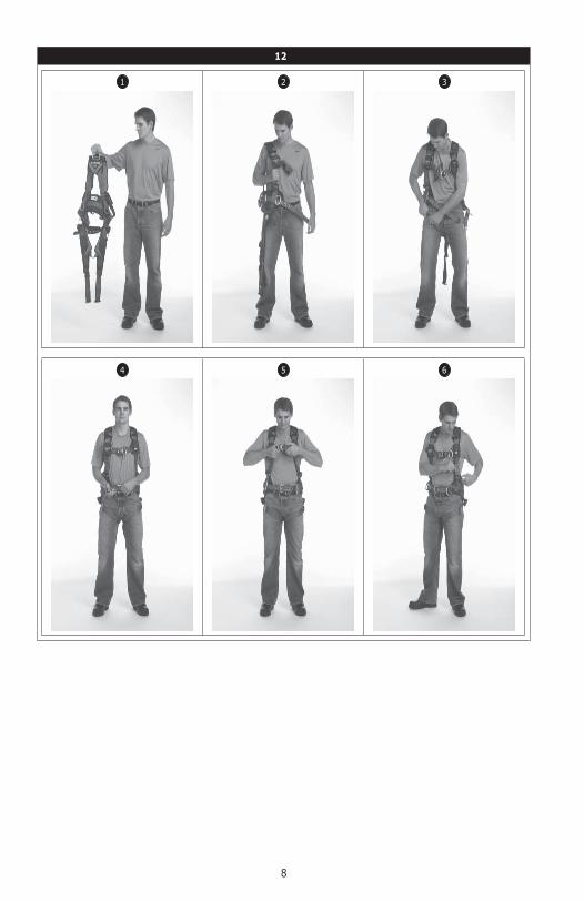
3.4 ADJUSTMENTS: Pro 3 Harnesses are equipped with a pair of Torso Adjusters for adjusting the Shoulder Straps. Figure 10 illustrates adjustment of the Torso Adjusters:
1. Parachute Torso Adjusters: To adjust the Shoulder Straps with the Parachute Torso Adjusters:
A. Pull on the free strap to tighten the Shoulder Strap. To loosen the Shoulder Strap, pull on the free strap and then back the strap through the Parachute Adjuster.
B. When properly adjusted, secure the free strap in the Strap Keeper.
3.5 PERSONAL SRD LOOP: Some Pro 3 Full Body Harnesses are equipped with a Personal SRD Loop that integrates the Dorsal D-Ring with attachment elements for Harness-Mounted Self-Retracting Devices (SRDs). Figure 11 illustrates attachment of the following 3M Self-Retracting Devices: (A) Nano-Lok™ Edge SRDs, (B) Twin Nano-Lok™ SRDs, (C) Single Nano-Lok™ SRDs, (D) Rebel™ SRDs. Other manufacturers’ SRDs can also be mounted on the Pro 3 Harness in similar fashion. See the SRD manufacturer’s instructions for requirements and installation instructions specifi c to the SRD.
Contact 3M with any questions or concerns regarding compatibility of your SRD with the Personal SRD Loop.
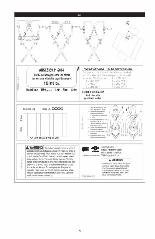
3.6 DONNING AND FITTING THE PRO 3 FULL BODY HARNESS: Figure 16 illustrates donning and fi tting of the Pro 3 Full Body Harness. Prior to each use, inspect the harness per the checklist on the “Inspection and Maintenance Log (Table 1)”. To don and fi t the harness:
Procedures for buckling and adjusting the straps on you Pro 3 Harness will vary with the harness model. See Sections 3.3 thru 3.4 and Figures 9 thru 10 for details.
1. Lift up and hold the harness by the back Dorsal D-Ring. Ensure the straps are not twisted.
2. Grasp the Shoulder Straps and slip the harness onto one arm. The Dorsal D-Ring will be located on your back side. Ensure that the straps are not tangled and hang freely. Slip your free arm into the harness and position the Shoulder Straps on top of your shoulders. The Chest Strap and Chest Buckle will be positioned on the front side when worn properly.
3. Reach between your legs and grasp the Leg Strap on your right side. Bring the strap up between your legs; buckle to the mating buckle on your right hip, and adjust the Leg Strap for a snug comfortable fi t (see Section 3.3 for buckle operation). When properly adjusted, tuck the loose end of the Leg Strap under the Strap Keeper.
Repeat this process to buckle and adjust the left Leg Strap.
4. Adjust and buckle the Tongue Buckle Waist Belt if present. (see Section 3.3 for Tongue Buckle operation).
15
5. Buckle and adjust the Chest Strap (see Section 3.3 for buckle operation). The Chest Strap should be 6 in. (15 cm) down from the top of your shoulders. When properly adjusted, tuck the loose end of the Chest Strap under the Strap Keeper.
6. Adjust the Shoulder Straps for a Snug Fit with the Torso Adjusters (see Section 3.4 for Torso Adjuster operation). Left and right sides of Shoulder Straps should be adjusted to the same length and the Chest Strap should be centered on your lower chest, 6 in. (15 cm) down from the shoulders. The back Dorsal D-Ring should be centered between your Shoulder Blades. The front Sternal D-Ring, if present, should be located laterally within 2 in. (51 mm) of the vertical centerline of the harness.
3.7 USE OF FALL ARREST D-RING OR ATTACHMENT ELEMENT: For Fall Arrest applications connect to the Dorsal D-ring or attachment element on your back, between your shoulder blades. Side D-rings, if present, are for Positioning or Restraint applications only. Shoulder D-rings are for Rescue or Retrieval applications only. The front Sternal D-ring is for Ladder Climbing or Positioning. D-rings on a Suspension Seat are for Suspension or Positioning applications only. (See Section 1.1.).
3.8 MAKING CONNECTIONS: When using a hook to connect to an anchorage or when coupling components of the system together, ensure roll-out cannot occur. Roll-out occurs when interference between the hook and mating connector causes the hook gate to unintentionally open and release. Self-locking snap hooks and carabiners should be used to reduce the possibility of roll-out. Do not use hooks or connectors that will not completely close over the attachment object. See subsystem manufacturer’s instructions for more information on making connections.
3.9 CONNECTING SYSTEM COMPONENTS: After fi tting the Pro 3 Harness the user may then connect to other system components. Follow the guidelines in Section 2 and the manufacturer’s instructions included with the component.
4.0 INSPECTION
4.1 INSPECTION FREQUENCY: The Pro 3 Full Body Harness must be inspected at the intervals defi ned in Section 2.2. Inspection procedures are described in the “Inspection and Maintenance Log” (Table 1).
4.2 DEFECTS: If inspection reveals a defective condition, remove the harness from service immediately and destroy.
4.3 PRODUCT LIFE: The functional life of Pro 3 Harnesses is determined by work conditions and maintenance. As long as the product passes inspection criteria, it may remain in service.
5.0 MAINTENANCE, SERVICING, STORAGE
5.1 CLEANING INSTRUCTIONS: Clean the Pro 3 Full Body Harness as follows:
1. Spot clean the harness with water and a mild soap solution.
Use a bleach-free detergent when washing the harness and pads. Fabric softener or dryer sheets SHOULD NOT be used when laundering and drying the harness and pads.
2. Water temperature for wash and rinse must not exceed 160° F (70° C).
3. The harness and pads may be air dried or tumble dried on low heat not exceeding 200° F (90° C).
More information on cleaning is available from 3M. If you have questions concerning the condition of your harness, or have any doubt about putting it into service, contact 3M.
5.2 AUTHORIZED SERVICE: Additional maintenance and servicing procedures must be completed by a factory authorized service center. Authorization must be in writing. Do not attempt to disassemble the unit.
5.3 STORAGE AND TRANSPORT: Store and transport the Pro 3 Full Body Harness in a cool, dry, clean environment out of direct sunlight. Avoid areas where chemical vapors may exist. Thoroughly inspect the harness after extended storage.
6.0 LABELING: Figure 13 illustrates product labels and their location on the Pro 3 Full Body Harness. All labeling must be present and fully legible.
16
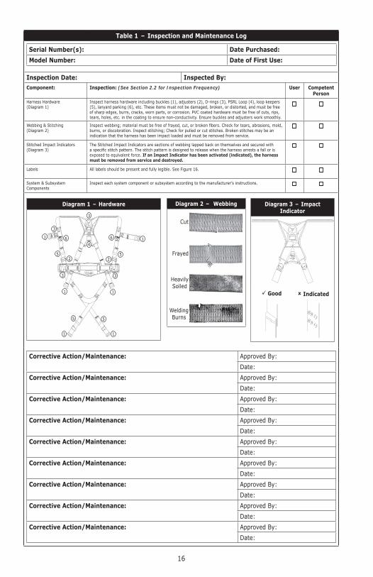
Table 1 – Inspection and Maintenance Log
Serial Number(s): Date Purchased:
Model Number: Date of First Use:
Inspection Date: Inspected By:Component: Inspection: (See Section 2.2 for Inspection Frequency) User Competent
Person
Harness Hardware(Diagram 1)
Inspect harness hardware including buckles (1), adjusters (2), D-rings (3), PSRL Loop (4), loop keepers (5), lanyard parking (6), etc. These items must not be damaged, broken, or distorted, and must be free of sharp edges, burrs, cracks, worn parts, or corrosion. PVC coated hardware must be free of cuts, rips, tears, holes, etc. in the coating to ensure non-conductivity. Ensure buckles and adjusters work smoothly.
Webbing & Stitching(Diagram 2)
Inspect webbing; material must be free of frayed, cut, or broken fi bers. Check for tears, abrasions, mold, burns, or discoloration. Inspect stitching; Check for pulled or cut stitches. Broken stitches may be an indication that the harness has been impact loaded and must be removed from service.
Stitched Impact Indicators(Diagram 3)
The Stitched Impact Indicators are sections of webbing lapped back on themselves and secured with a specifi c stitch pattern. The stitch pattern is designed to release when the harness arrests a fall or is exposed to equivalent force. If an Impact Indicator has been activated (indicated), the harness must be removed from service and destroyed.
Labels All labels should be present and fully legible. See Figure 16.
System & Subsystem Components
Inspect each system component or subsystem according to the manufacturer’s instructions.
Diagram 1 – Hardware
3
4
3
1 16 6
52
52
3 3
11
55
11
Diagram 2 – Webbing
Cut
Frayed
HeavilySoiled
WeldingBurns
Diagram 3 – Impact Indicator
Good Indicated
Corrective Action/Maintenance: Approved By:
Date:
Corrective Action/Maintenance: Approved By:
Date:
Corrective Action/Maintenance: Approved By:
Date:
Corrective Action/Maintenance: Approved By:
Date:
Corrective Action/Maintenance: Approved By:
Date:
Corrective Action/Maintenance: Approved By:
Date:
Corrective Action/Maintenance: Approved By:
Date:
Corrective Action/Maintenance: Approved By:
Date:
Corrective Action/Maintenance: Approved By:
Date:
i
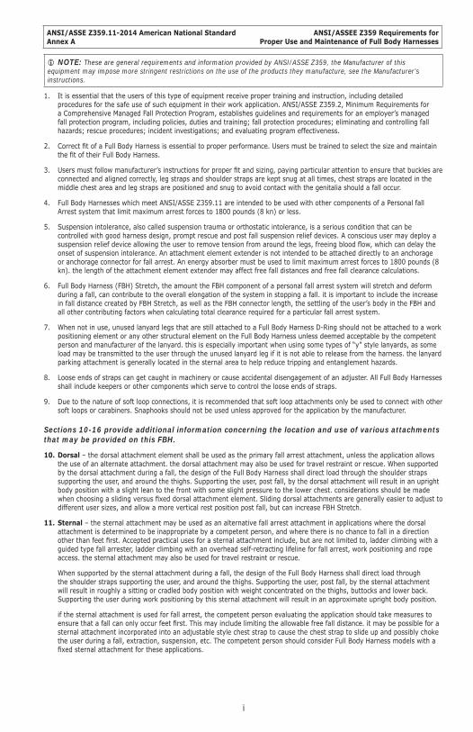
ANSI/ASSE Z359.11-2014 American National StandardAnnex A
ANSI/ASSEE Z359 Requirements forProper Use and Maintenance of Full Body Harnesses
NOTE: These are general requirements and information provided by ANSI/ASSE Z359, the Manufacturer of this equipment may impose more stringent restrictions on the use of the products they manufacture, see the Manufacturer’s instructions.
1. It is essential that the users of this type of equipment receive proper training and instruction, including detailed procedures for the safe use of such equipment in their work application. ANSI/ASSE Z359.2, Minimum Requirements for a Comprehensive Managed Fall Protection Program, establishes guidelines and requirements for an employer’s managed fall protection program, including policies, duties and training; fall protection procedures; eliminating and controlling fall hazards; rescue procedures; incident investigations; and evaluating program effectiveness.
2. Correct fi t of a Full Body Harness is essential to proper performance. Users must be trained to select the size and maintain the fi t of their Full Body Harness.
3. Users must follow manufacturer’s instructions for proper fi t and sizing, paying particular attention to ensure that buckles are connected and aligned correctly, leg straps and shoulder straps are kept snug at all times, chest straps are located in the middle chest area and leg straps are positioned and snug to avoid contact with the genitalia should a fall occur.
4. Full Body Harnesses which meet ANSI/ASSE Z359.11 are intended to be used with other components of a Personal fall Arrest system that limit maximum arrest forces to 1800 pounds (8 kn) or less.
5. Suspension intolerance, also called suspension trauma or orthostatic intolerance, is a serious condition that can be controlled with good harness design, prompt rescue and post fall suspension relief devices. A conscious user may deploy a suspension relief device allowing the user to remove tension from around the legs, freeing blood fl ow, which can delay the onset of suspension intolerance. An attachment element extender is not intended to be attached directly to an anchorage or anchorage connector for fall arrest. An energy absorber must be used to limit maximum arrest forces to 1800 pounds (8 kn). the length of the attachment element extender may affect free fall distances and free fall clearance calculations.
6. Full Body Harness (FBH) Stretch, the amount the FBH component of a personal fall arrest system will stretch and deform during a fall, can contribute to the overall elongation of the system in stopping a fall. it is important to include the increase in fall distance created by FBH Stretch, as well as the FBH connector length, the settling of the user’s body in the FBH and all other contributing factors when calculating total clearance required for a particular fall arrest system.
7. When not in use, unused lanyard legs that are still attached to a Full Body Harness D-Ring should not be attached to a work positioning element or any other structural element on the Full Body Harness unless deemed acceptable by the competent person and manufacturer of the lanyard. this is especially important when using some types of “y” style lanyards, as some load may be transmitted to the user through the unused lanyard leg if it is not able to release from the harness. the lanyard parking attachment is generally located in the sternal area to help reduce tripping and entanglement hazards.
8. Loose ends of straps can get caught in machinery or cause accidental disengagement of an adjuster. All Full Body Harnesses shall include keepers or other components which serve to control the loose ends of straps.
9. Due to the nature of soft loop connections, it is recommended that soft loop attachments only be used to connect with other soft loops or carabiners. Snaphooks should not be used unless approved for the application by the manufacturer.
Sections 10-16 provide additional information concerning the location and use of various attachments that may be provided on this FBH.
10. Dorsal – the dorsal attachment element shall be used as the primary fall arrest attachment, unless the application allows the use of an alternate attachment. the dorsal attachment may also be used for travel restraint or rescue. When supported by the dorsal attachment during a fall, the design of the Full Body Harness shall direct load through the shoulder straps supporting the user, and around the thighs. Supporting the user, post fall, by the dorsal attachment will result in an upright body position with a slight lean to the front with some slight pressure to the lower chest. considerations should be made when choosing a sliding versus fi xed dorsal attachment element. Sliding dorsal attachments are generally easier to adjust to different user sizes, and allow a more vertical rest position post fall, but can increase FBH Stretch.
11. Sternal – the sternal attachment may be used as an alternative fall arrest attachment in applications where the dorsal attachment is determined to be inappropriate by a competent person, and where there is no chance to fall in a direction other than feet fi rst. Accepted practical uses for a sternal attachment include, but are not limited to, ladder climbing with a guided type fall arrester, ladder climbing with an overhead self-retracting lifeline for fall arrest, work positioning and rope access. the sternal attachment may also be used for travel restraint or rescue.
When supported by the sternal attachment during a fall, the design of the Full Body Harness shall direct load through the shoulder straps supporting the user, and around the thighs. Supporting the user, post fall, by the sternal attachment will result in roughly a sitting or cradled body position with weight concentrated on the thighs, buttocks and lower back. Supporting the user during work positioning by this sternal attachment will result in an approximate upright body position.
if the sternal attachment is used for fall arrest, the competent person evaluating the application should take measures to ensure that a fall can only occur feet fi rst. This may include limiting the allowable free fall distance. it may be possible for a sternal attachment incorporated into an adjustable style chest strap to cause the chest strap to slide up and possibly choke the user during a fall, extraction, suspension, etc. The competent person should consider Full Body Harness models with a fi xed sternal attachment for these applications.
ii
ANSI/ASSE Z359.11-2014 American National StandardAnnex A
ANSI/ASSEE Z359 Requirements forProper Use and Maintenance of Full Body Harnesses
12. Frontal – the frontal attachment serves as a ladder climbing connection for guided type fall arresters where there is no chance to fall in a direction other than feet fi rst, or may be used for work positioning. Supporting the user, post fall or during work positioning, by the frontal attachment will result in a sitting body position, with the upper torso upright, with weight concentrated on the thighs and buttocks. When supported by the frontal attachment the design of the Full Body Harness shall direct load directly around the thighs and under the buttocks by means of the sub-pelvic strap.
if the frontal attachment is used for fall arrest, the competent person evaluating the application should take measures to ensure that a fall can only occur feet fi rst. This may include limiting the allowable free fall distance.
13. Shoulder – the shoulder attachment elements shall be used as a pair, and are an acceptable attachment for rescue and entry/retrieval. the shoulder attachment elements shall not be used for fall arrest. it is recommended that the shoulder attachment elements be used in conjunction with a yoke which incorporates a spreader element to keep the Full Body Harness shoulder straps separate.
14. Waist, Rear – the waist, rear attachment shall be used solely for travel restraint. the waist, rear attachment element shall not be used for fall arrest. Under no circumstances is it acceptable to use the waist, rear attachment for purposes other than travel restraint. the waist, rear attachment shall only be subjected to minimal loading through the waist of the user, and shall never be used to support the full weight of the user.
15. Hip – the hip attachment elements shall be used as a pair, and shall be used solely for work positioning. the hip attachment elements shall not be used for fall arrest. Hip attachments are often used for work positioning by arborists, utility workers climbing poles and construction workers tying rebar and climbing on form walls. Users are cautioned against using the hip attachment elements (or any other rigid point on the Full Body Harness) to store the unused end of a fall arrest lanyard, as this may cause a tripping hazard, or, in the case multiple leg lanyards, could cause adverse loading to the Full Body Harness and the wearer through the unused portion of the lanyard.
16. Suspension Seat – the suspension seat attachment elements shall be used as a pair, and shall be used solely for work positioning. the suspension seat attachment elements shall not be used for fall arrest. Suspension seat attachments are often used for prolonged work activities where the user is suspended, allowing the user to sit on the suspension seat formed between the two attachment elements. An example of this use would be window washers on large buildings.
User Inspection, Maintenance, and Storage of Equipment
Users of personal fall arrest systems shall, at a minimum, comply with all manufacturer instructions regarding the inspection, maintenance and storage of the equipment. the user’s organization shall retain the manufacturer’s instructions and make them readily available to all users. See ANSI/ASSE Z359.2, Minimum Requirements for a Comprehensive Managed Fall Protection Program, regarding user inspection, maintenance and storage of equipment.
1. In addition to the inspection requirements set forth in the manufacturer’s instructions, the equipment shall be inspected by the user before each use and, additionally, by a competent person, other than the user, at interval of no more than one year for:
• Absence or illegibility of markings.
• Absence of any elements affecting the equipment form, fi t or function.
• Evidence of defects in, or damage to, hardware elements including cracks, sharp edges, deformation, corrosion, chemical attack, excessive heating, alteration and excessive wear.
• Evidence of defects in or damage to strap or ropes including fraying, unsplicing, unlaying, kinking, knotting, roping, broken or pulled stitches, excessive elongation, chemical attack, excessive soiling, abrasion, alteration, needed or excessive lubrication, excessive aging and excessive wear.
2. Inspection criteria for the equipment shall be set by the user’s organization. Such criteria for the equipment shall equal or exceed the criteria established by this standard or the manufacturer’s instructions, whichever is greater.
3. When inspection reveals defects in, damage to, or inadequate maintenance of equipment, the equipment shall be permanently removed from service or undergo adequate corrective maintenance, by the original equipment manufacturer or their designate, before return to service.
Maintenance and Storage
1. Maintenance and storage of equipment shall be conducted by the user’s organization in accordance with the manufacturer’s instructions. Unique issues, which may arise due to conditions of use, shall be addressed with the manufacturer.
2. Equipment which is in need of, or scheduled for, maintenance shall be tagged as unusable and removed from service.
3. Equipment shall be stored in a manner as to preclude damage from environmental factors such as temperature, light, UV, excessive moisture, oil, chemicals and their vapors or other degrading elements.

ADDITIONAL HARNESS MODELS:Additional Protecta Harness models not listed in Figure 1, but covered by this Instruction Manual are as follows:
11912001191200C11912011191201C1191201CH1191201H11912021191202C11912031191203C1191203CH11912041191204C11912051191205C1191205CH11912061191206C11912071191207C11912081191208H11912091191209H11912101191210H11912111191212CH1191212H1191213CH1191213H1191214CH1191214H11912151191215C11912161191216C1191216CH11912171191217C11912181191218C1191219C1191220C1191221C1191222C11912231191223C11912241191224C11912251191225C11912261191226H11912271191227H11912281191229
11912301191230C11912311191231C1191231CH11912321191232C11912331191233C11912341191234C11912351191235C11912361191236C11912371191237C1191237CH1191237H11912381191238C1191238CH1191238H11912391191239CH1191239H11912401191240C11912411191241C1191241CH11912421191242C1191242CH11912431191243C1191243CH1191243H1191244CH11912521191252C1191252CH1191252H11912531191253C1191253CH1191253H11912541191254C1191254CH1191254H11912551191255C11912561191256C11912571191257C1191258
1191258C11912591191259C11912601191260C11912611191261C11912621191262C11912631191263C11912641191264C11912651191265C11912661191266C11912671191267C11912681191268C119126911912701191270H11912711191271H11912721191272C11912731191273C1191273CH11912741191274C1191274CH11912751191275C11912761191276C11912771191277C11912781191278C11912791191279C11912801191280C11912811191281C1191282CH11912831191283C11912841191284C11912851191285C119128611912871191288
119128911912901191295H1191296H1191297H119129811912991191300119130111913021191303119130411913071191310H11913111191311H1191312119131311913141191315119131611913171191318119131911913201191321119132611913321191333119133411913351191336119133711913381191339119134011913411191342119134311913441191345119134611913481191350H11913521191354H1191355H1191356119135811913591191360CH1191361CH1191362CH1191363CH1191364CH1191365CH11913661191367
11913691191370119137111913721191379119138011913811191382119138311913841191384H1191385119138611913871191388119138911913901191391119139211913931191395119139611913971191398119140511914061191406H11914071191407H11914081191408H11914091191409H11914101191412C1191426C1191427C1191428C11914431191448119144911914501191478CH119150211915031191504119150511915101191511119151211915131191514119151511915161191517119151811915191191520
119152111915221191523119152411915251191526119152711915281191529119153011915311191539119154011915701191571119157211915731191574119157511915761191577119157811915791191580119158111915821191586H1191587H1191588H1191589H11919971310075HAB10112AB10113AB10113017AB10113HAB10114AB10114017AB10115AB10115017AB10312AB10313AB10314AB104121AB104125AB104131AB104135AB104141AB104145AB104151AB105125AB105135AB105145AB11122AB11123AB11123006AB11123018AB11124
AB11125AB11212AB11213AB11214AB114125AB114135AB114135OTEAB114145AB115125AB115135AB115145AB118121AB118131AB118141AB118151AB13012AB13013AB13013018AB13014AB13023007AB13023009AB13023010AB13024009AB13024010AB13025009AB13122AB13123AB13123010AB13124AB13222AB13223AB13224AB13312AB13313AB13314AB13422AB13423AB13424AB140121AB140131AB14013118AB140141AB14014118AB140151AB14023111AB15012AB15013AB15014AB15015AB15112AB15113AB15113018AB15114AB15114018AB15115AB15115018AB15123007AB15123008
AB15522AB15523AB15524AB15622AB15623AB15624AB17510-3XLAB17510-XLAB17510-XXLAB17532AB17536AB17540-XLAB17550AB17550-XLAB17560AB17560-XLAB17610AB17611AB21012AB21012018AB21013AB21013018AB21014AB21014018AB21015AB21022005AB21023004AB21023005AB21024004AB21024005AB21122AB21123AB21124AB21125AB21162013AB21163013AB21164013AB23312AB23313AB23314AB240121AB240131AB24013118AB240141AB24014118AB25012AB25013AB25014AB25113AB260126AB260136AB260146
I S O9 0 0 1
USA3833 SALA Way Red Wing, MN 55066-5005 Toll Free: 800.328.6146Phone: 651.388.8282Fax: [email protected]
BrazilRua Anne Frank, 2621Boqueirão Curitiba PR81650-020BrazilPhone: [email protected]
MexicoCalle Norte 35, 895-ECol. Industrial VallejoC.P. 02300 AzcapotzalcoMexico D.F.Phone: (55) [email protected]
ColombiaCompañía Latinoamericana de Seguridad S.A.S.Carrera 106 #15-25 Interior 105 Manzana 15Zona Franca - Bogotá, ColombiaPhone: 57 1 [email protected]
Canada260 Export Boulevard Mississauga, ON L5S 1Y9 Phone: 905.795.9333 Toll-Free: 800.387.7484 Fax: 888.387.7484 [email protected]
EMEA (Europe, Middle East, Africa)EMEA Headquarters:5a Merse RoadNorth Moons MoatRedditch, WorcestershireB98 9HL UKPhone: + 44 (0)1527 548 000Fax: + 44 (0)1527 591 [email protected]
France:Le Broc CenterZ.I. 1re Avenue - BP1506511 Carros Le Broc CedexFrancePhone: + 33 04 97 10 00 10Fax: + 33 04 93 08 79 [email protected]
Australia & New Zealand95 Derby StreetSilverwaterSydney NSW 2128AustraliaPhone: +(61) 2 8753 7600Toll-Free : 1800 245 002 (AUS)Toll-Free : 0800 212 505 (NZ) Fax: +(61) 2 8753 7603 [email protected]
AsiaSingapore:1 Yishun Avenue 7Singapore 408731Phone: +65 - 65587758Fax: +65 - [email protected]
Shanghai:19/F, L’Avenue, No.99 Xian Xia RdShanghai 200051, P R China Phone: +86 21 62539050Fax: +86 21 [email protected]
3M.com/FallProtection
U.S. PRODUCT WARRANTY, LIMITED REMEDY AND LIMITATION OF LIABILITY
WARRANTY: THE FOLLOWING IS MADE IN LIEU OF ALL WARRANTIES OR CONDITIONS, EXPRESS OR IMPLIED, INCLUDING THE IMPLIED WARRANTIES OR CONDITIONS OF MERCHANTABILITY OR FITNESS FOR A PARTICULAR PURPOSE. Unless otherwise provided by applicable law, 3M fall protection products are warranted against factory defects in workmanship and materials for a period of one year from the date of installation or fi rst use by the original owner.LIMITED REMEDY: Upon written notice to 3M, 3M will repair or replace any product determined by 3M to have a factory defect in workmanship or materials. 3M reserves the right to require product be returned to its facility for evaluation of warranty claims. This warranty does not cover product damage due to wear, abuse, misuse, damage in transit, failure to maintain the product or other damage beyond 3M’s control. 3M will be the sole judge of product condition and warranty options.This warranty applies only to the original purchaser and is the only warranty applicable to 3M’s fall protection products. Please contact 3M’s customer service department at 800-328-6146 or via email at [email protected] for assistance.LIMITATION OF LIABILITY: TO THE EXTENT PERMITTED BY APPLICABLE LAW, 3M IS NOT LIABLE FOR ANY INDIRECT, INCIDENTAL, SPECIAL OR CONSEQUENTIAL DAMAGES INCLUDING, BUT NOT LIMITED TO LOSS OF PROFITS, IN ANY WAY RELATED TO THE PRODUCTS REGARDLESS OF THE LEGAL THEORY ASSERTED.