Embed Size (px)
Citation preview
protectionguide
protectionand control
I >
GROUPE SCHNEIDER
MERLIN GERINmastering electrical power
Merlin Gerin protection guide 1
presentation
contents page
presentation 1
grounding systems 3
short-circuit currents 9
discrimination 15
electrical system protection 21
transformer protection 29
motor protection 35
AC generator protection 41
capacitor protection 47
sensors 53
lexicon overcurrent protectionI >
I <–
IN
>
Ii >
I
∆I
I >U
U <
U >
P <––
Q <––
UN
>
> f >
generalities Protection devices continuously monitor theelectrical status of system units and causethem to be de-energized (e.g. tripped by acircuit breaker) when they are the site of adisturbance: short-circuit, insulation fault...
The objectives are:to contribute to protecting people against
electrical hazards,to prevent equipment damage (the power
produced by a three-phase short-circuit on aMV busbar can melt up to 50 kg of copperwithin 1 second, the temperature at thecentre of the arc can exceed 10,000°C),
to limit thermal, dielectric and mechanicalstress on equipment,
to maintain stability and service continuityin the system,
to protect adjacent installations(for example, by reducing induced voltage inadjacent circuits).
In order to attain these objectives, aprotection system should have the followingfeatures:
speed,discrimination,reliability.
Protection, however, has its limits: faultshave to actually occur in order for it to takeeffect. Protection cannot therefore preventdisturbances; it can only limit their duration.Furthermore, the choice of a protectionsystem is often a technical and economiccompromise between the availability andsafety of the electrical power supply.
The choice of a protective device is not theresult of isolated study, but rather one of themost important steps in the design of theelectrical system.Based on an analysis of the behaviour ofelectrical equipment (motors,transformers...) during faults and thephenomena produced, this guide is intendedto facilitate your choice of the most suitableprotective devices.
undervoltage protection
voltage restrainedovercurrent protection
Buchholz
differential protection neutral voltage displacementprotection
thermal overload protection reactive reverse powerprotection
negative sequenceunbalance protection
real reverse powerprotection
earth fault protection overvoltage protection
directional overcurrentprotection
over and underfrequencyprotection
2 protection guide Merlin Gerin
Merlin Gerin protection guide 3
introduction The choice of MV and HV grounding systemshas long been a topic of heated controversydue to the impossibility of finding a singlecompromise for the various types of electricalsystems. Experience acquired today enables apertinent choice to be made according to thespecific constraints of each system.
grounding systems
five grounding sytems Neutral potential can be grounded using fivemethods that differ according to the kind(capacitive, resistive, inductive) and value(zero to infinity) of the Zn impedanceconnection made between the neutral andearth:
Zn = ∞ ungrounded, no deliberateconnection,
Zn is a resistance with a fairly high value,Zn is a reactance with a generally low value,Zn is a reactance designed to compensate
for the system capacity,Zn = 0 - the neutral is directly grounded.
The selection criteria involve many aspects:technical characteristics (system function,
overvoltage, fault current, etc...),operation (service continuity, maintenance),safety,cost (investment and operating expenses),local and national customs.
In particular, there are two major technicalconsiderations which are, in fact, contradictory:
Reducing the level of overvoltageOvervoltage is of several origins:
lightning overvoltage, which all overheadsystems are exposed to, up to the user supplypoint,
internal system overvoltage caused byoperations and certain critical situations(resonance),
overvoltage resulting from an earth fault itselfand its clearance.
Reducing earth fault current (If).Fault current that is too high produces a wholeseries of consequences:
damage caused by the arc at the fault point;particularly the melting of magnetic circuits inrotary machines,
thermal withstand of cable shields,size and cost of earthing resistance,induction into adjacent telecommunication
systems,danger for people created by raised frame
potential.
Unfortunately, optimizing one of theserequirements is automatically to thedisadvantage of the other. Two typicalgrounding methods accentuate this contrast:
the ungrounded neutral system, whicheliminates the flow of earth fault currentthrough the neutral but causes the mostovervoltage,
the directly grounded neutral system, whichreduces overvoltage to a minimum, but causeshigh fault current.An intermediate solution is therefore oftenchosen: the impedance grounded neutralsystem.
difficulties and selectioncriteria
4 protection guide Merlin Gerin
grounding systems (cont.)
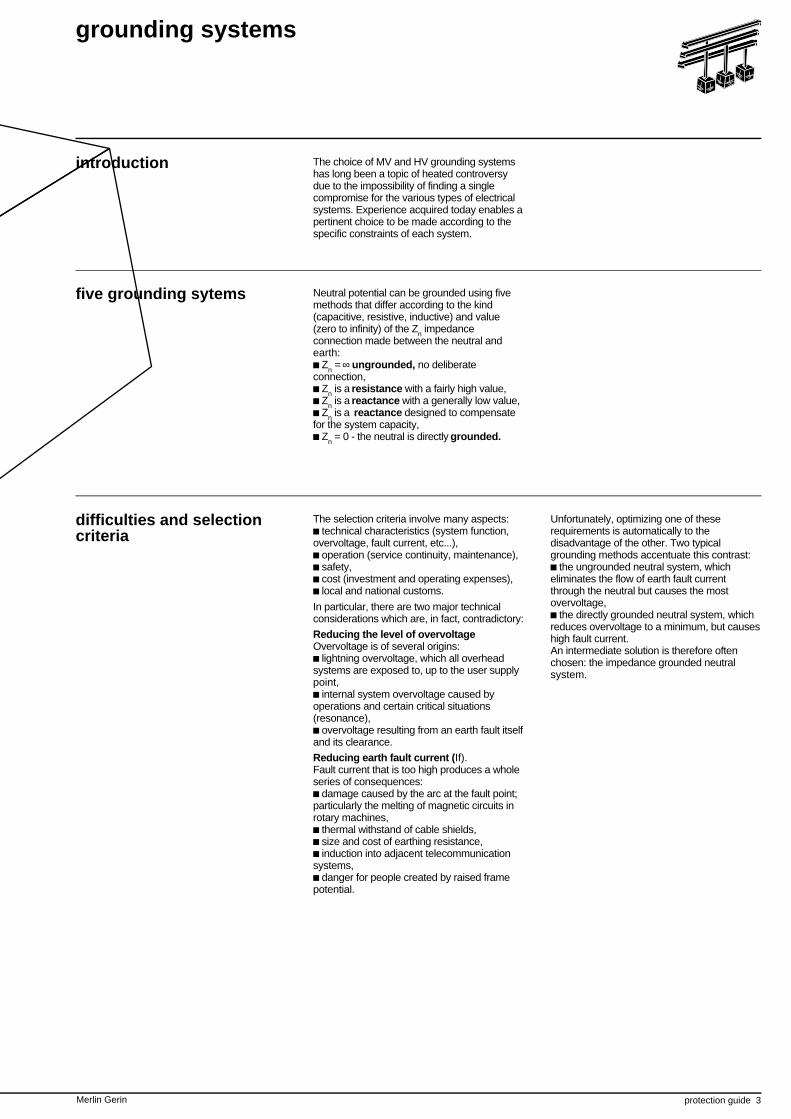
In this type of system, a phase-to-earth faultonly produces a weak current through thephase-to-earth capacity of the fault-freephases.It can be shown that Id = 3 CωV
c V being the simple voltage,c C the phase-to-earth capacity of a phase,c ω the frequency of the system (ω = 2πf).
The Id current can remain for a long time, inprinciple, without causing any damage sinceit does not exceed a few amperes(approximately 2 A per km for a 6 kV single-pole cable, with a 150 mm2 cross-section,PRC insulated, with a capacity of 0.63 µF/km).Action does not need to be taken to clear this1st fault, making this solution advantageous interms of maintaining service continuity.However, this brings about the followingconsquences:c if not cleared, the insulation fault must besignalled by a permanent insulationmonitor,c subsequent fault tracking requires devicemade all the more complex by the fact that it isautomatic, for quick identification of the faultyfeeder, and also maintenance personnelqualified to operate it,c if the 1st fault is not cleared, a second faultoccurring on another phase will cause a realtwo-phase short circuit through the earth,which will be cleared by the phase protections.
ungrounded
Id
AdvantageThe basic advantage is service continuitysince the very weak fault current preventsautomatic tripping.
DrawbacksThe failure to eliminate overvoltage throughthe earth can be a major handicap ifovervoltage is high. Also, when one phase isearthed, the others are at delta voltage(U = V.e) in relation to the earth increasingthe probability of a 2nd fault. Insulation costsare therefore higher since the delta voltagemay remain between the phase and earth fora long period as there is no automatic tripping.A maintenance department with the equipmentto quickly track the 1st insulation fault is alsorequired.
ApplicationsThis solution is often used for industrialsystems (≤ 15 kV) requiring service continuity.
Merlin Gerin protection guide 5
resistance grounding
Id
N
Rn
IN
>
accessible neutral
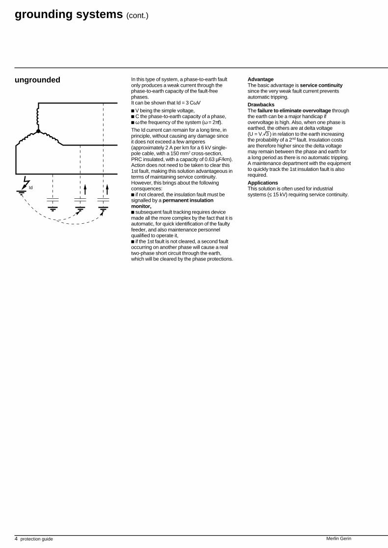
In this type of system, a resistive impedancelimits earth fault current Id, while still allowingproper evacuation of overvoltage. Protectionsmust however intervene automatically to clearthe first fault. In systems that feed rotatingmachines, the resistance is calculated so as toobtain an Id
current of 15 to 50 A.
This weak current must however be Id ≥ 2 Ic(Ic : total capacitive current in the system) inorder to reduce operation overvoltage and toenable simple detection.Distribution systems use higher ratings(100 to 1000 A) that are easier to detect andallow evacuation of lightning overvoltage.
AdvantagesThis system is a good compromise betweenweak fault current and good overvoltageevacuation. The protection devices are fairlysimple and discriminating and the current islimited.
Drawbacksc no service continuity; earth faults must becleared as soon as they occur,c the higher the voltage and level of currentlimitation, the higher the cost of the earthingresistance.
ApplicationsPublic and industrial MV distribution systems.
Earthing resistanceIf the neutral is accessible (star-connectedtransformer), the earthing resistance isinserted between the neutral and earth.When the neutral is not accessible or whendetermined by the discrimination study, anartificial neutral point is established(zero sequence generator) using a coil ora special transformer with a very lowzero sequence reactance.
Rn
IN
>
non accessible neutral
The relay is set according to the fault current Idthat is calculated leaving out the zerosequence impedance of the source and of theconnection in relation to impedance Rn andtaking the following 2 rules into account:c setting > 1.3 times system capacitive currentdownstream from the protection,c setting at approximately 20 % of maximumearth fault current.Also, if 3 CTs are used for detection,the setting must not be less than 10%of the CT rating to take into consideration theuncertainty linked to:v assymmetry of transient currents,v differences in performance level.
ProtectionsThe detection of weak fault current Id requiresprotections other than overcurrent phaserelays.These “earth fault" protections detect faultcurrent:c directly in the neutral earthingconnection 1 ,c or within the system by measuring thevectorial sum of the 3 currents using:v 3 CTs feeding the phase overcurrentprotections 2 ,v a core balance CT - (accurate solution - to beused preferably) 3 .
1 2 3
IN
>
IN
>
IN
>
6 protection guide Merlin Gerin
grounding systems (cont.)
For system voltage above 40 kV,it is preferable to use reactance ratherthan a resistance because of the difficultiesarising from heat emission in the event of afault.
reactance grounding
compensation reactancegrounding
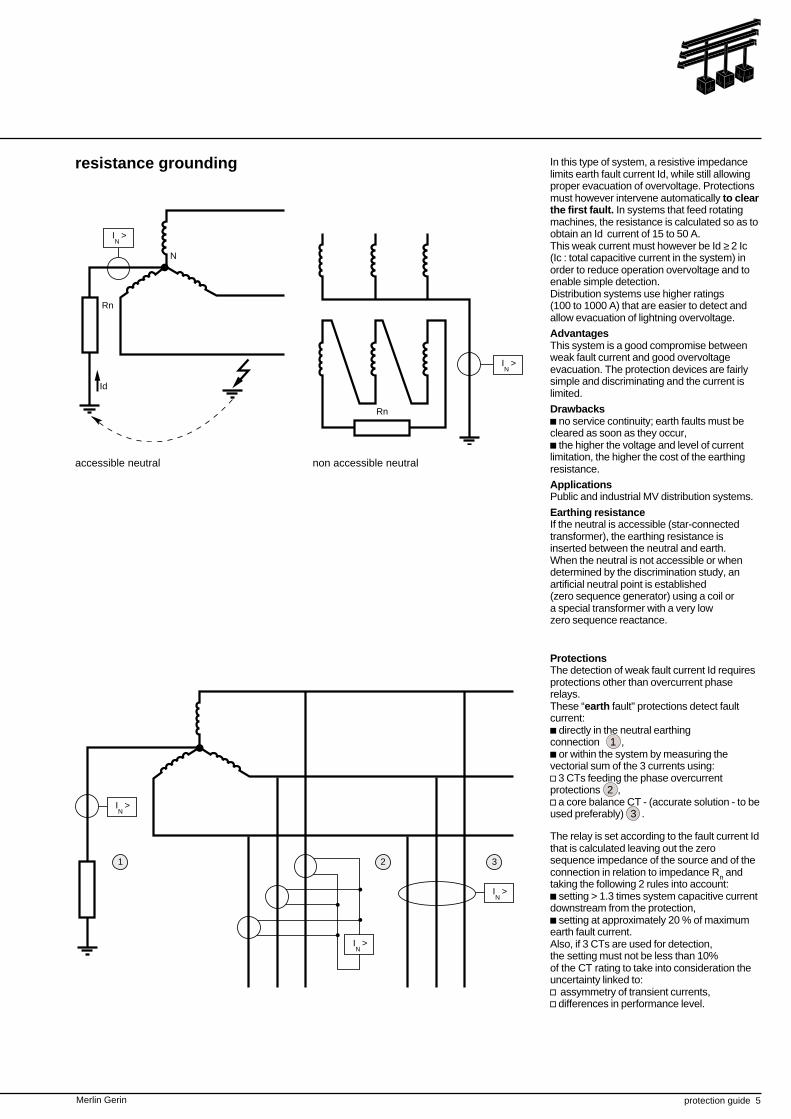
This system is used to compensatefor capacitive current in the system.Fault current is the sum of the currentswhich flow through the following circuits:c reactance grounding,c fault-free phase capacitance with respectto earth.The currents may compensate for eachother since:c one is inductive (in the grounding),c the other one is capacitive (in the fault-freephase capacitances).They are therefore opposite in phase.
AdvantageThe system reduces fault current, even ifthe phase-to-earth capacitance is high.
DrawbackThe cost of reactance grounding may behigh due to the need to modify the reactancevalue in order to adapt compensation.
LN
Id
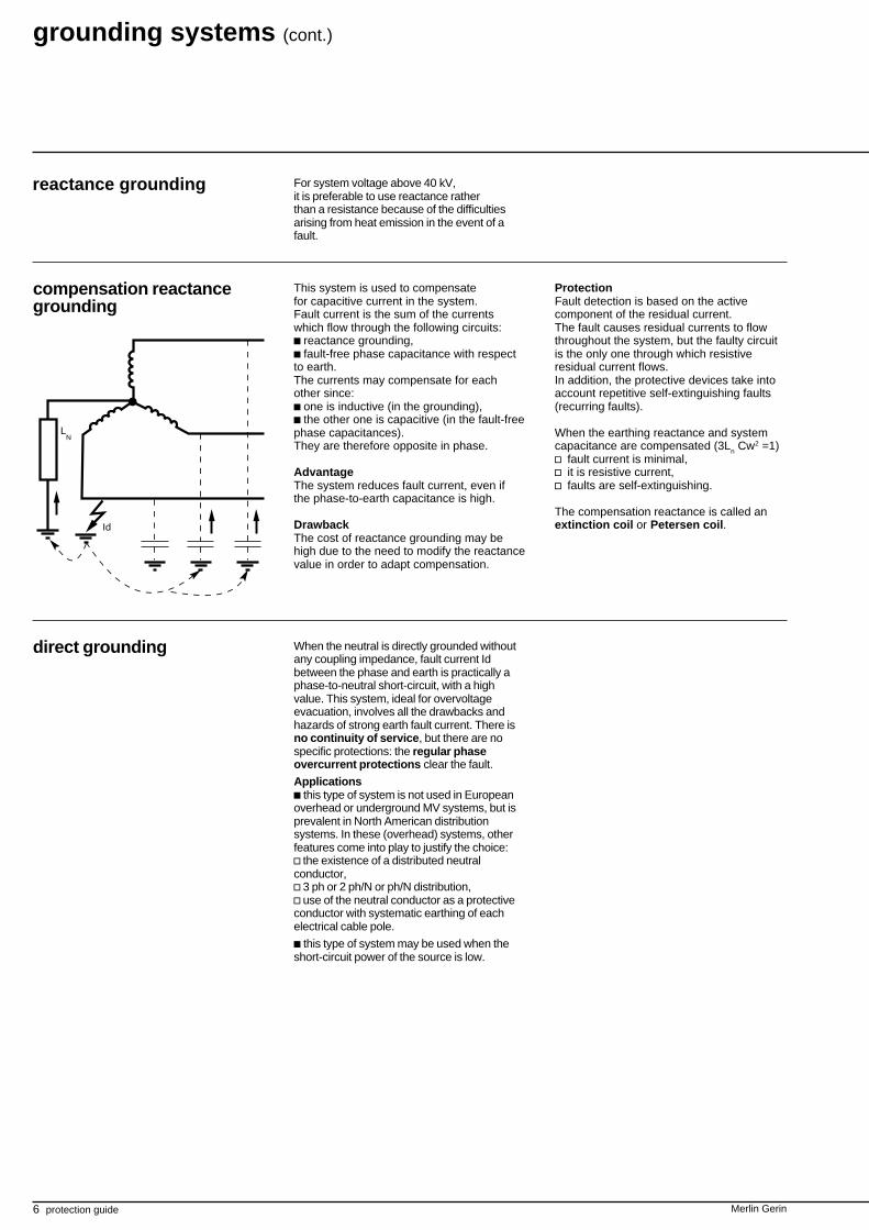
direct grounding When the neutral is directly grounded withoutany coupling impedance, fault current Idbetween the phase and earth is practically aphase-to-neutral short-circuit, with a highvalue. This system, ideal for overvoltageevacuation, involves all the drawbacks andhazards of strong earth fault current. There isno continuity of service, but there are nospecific protections: the regular phaseovercurrent protections clear the fault.
Applicationsc this type of system is not used in Europeanoverhead or underground MV systems, but isprevalent in North American distributionsystems. In these (overhead) systems, otherfeatures come into play to justify the choice:v the existence of a distributed neutralconductor,v 3 ph or 2 ph/N or ph/N distribution,v use of the neutral conductor as a protectiveconductor with systematic earthing of eachelectrical cable pole.
c this type of system may be used when theshort-circuit power of the source is low.
ProtectionFault detection is based on the activecomponent of the residual current.The fault causes residual currents to flowthroughout the system, but the faulty circuitis the only one through which resistiveresidual current flows.In addition, the protective devices take intoaccount repetitive self-extinguishing faults(recurring faults).
When the earthing reactance and systemcapacitance are compensated (3Ln Cw2 =1)v fault current is minimal,v it is resistive current,v faults are self-extinguishing.
The compensation reactance is called anextinction coil or Petersen coil.
Merlin Gerin protection guide 7
8 protection guide Merlin Gerin
Merlin Gerin protection guide 9
introduction A short circuit is one of the major incidentsaffecting electrical systems.
The consequences are often serious, if notdramatic:c a short circuit disturbs the systemenvironment around the fault point bycausing a sudden drop in voltage,c it requires a part of the system (often alarge part) to be disconnected through theoperation of the protection devices,c all equipment and connections (cables,lines) subjected to a short circuit undergostrong mechanical stress (electrodynamicforces) which can cause breaks, andthermal stress which can melt conductorsand destroy insulation,c at the fault point, there is often a highpower electrical arc, causing very heavydamage that can quickly spread all around.
short-circuit currents
Although short circuits are less and lesslikely to occur in modern well-designed, well-operating installations, the seriousconsequences they can cause are anincentive to implement all possible means toswiftly detect and attenuate them.
The short circuit value at different points inthe system is essential data in defining thecables, busbars and all breaking andprotection devices as well as their settings.
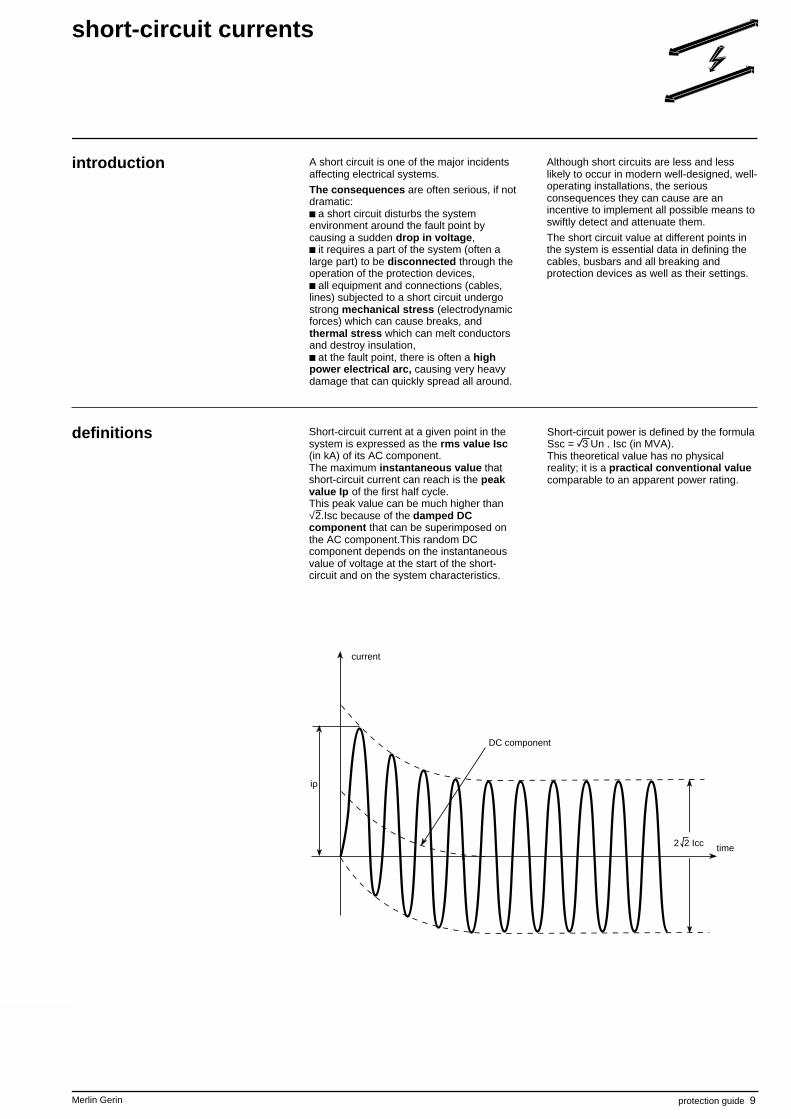
Short-circuit current at a given point in thesystem is expressed as the rms value Isc(in kA) of its AC component.The maximum instantaneous value thatshort-circuit current can reach is the peakvalue Ip of the first half cycle.This peak value can be much higher than√2.Isc because of the damped DCcomponent that can be superimposed onthe AC component.This random DCcomponent depends on the instantaneousvalue of voltage at the start of the short-circuit and on the system characteristics.
Short-circuit power is defined by the formulaSsc = eUn . Isc (in MVA).This theoretical value has no physicalreality; it is a practical conventional valuecomparable to an apparent power rating.
iρ
2 2 Icc
current
time
DC component
definitions
10 protection guide Merlin Gerin
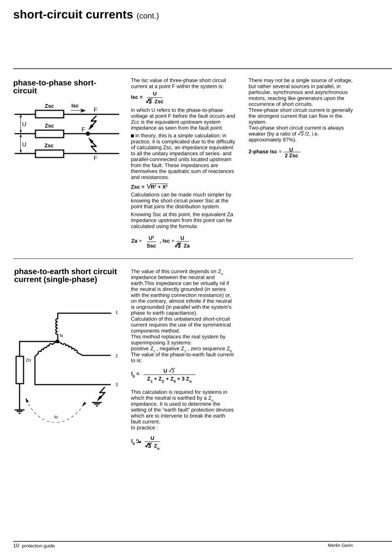
The Isc value of three-phase short circuitcurrent at a point F within the system is:
in which U refers to the phase-to-phasevoltage at point F before the fault occurs andZcc is the equivalent upstream systemimpedance as seen from the fault point.
c in theory, this is a simple calculation; inpractice, it is complicated due to the difficultyof calculating Zsc, an impedance equivalentto all the unitary impedances of series- andparallel-connnected units located upstreamfrom the fault. These impedances arethemselves the quadratic sum of reactancesand resistances.
Zsc = R2 + X2
Calculations can be made much simpler byknowing the short-circuit power Ssc at thepoint that joins the distribution system.
Knowing Ssc at this point, the equivalent Zaimpedance upstream from this point can becalculated using the formula:
short-circuit currents (cont.)
U
U
F
F
F
Isc =
U2
SscZa = , Isc = U
eeeee Za
phase-to-phase short-circuit
There may not be a single source of voltage,but rather several sources in parallel, inparticular, synchronous and asynchronousmotors, reacting like generators upon theoccurrence of short circuits.Three-phase short circuit current is generallythe strongest current that can flow in thesystem.Two-phase short circuit current is alwaysweaker (by a ratio of e/2, i.e.approximately 87%).
2-phase Isc =
Io
1
2
3
N
Zn
phase-to-earth short circuitcurrent (single-phase)
Zsc
Zsc
Zsc Isc
V
U
eeeee Zsc
The value of this current depends on Znimpedance between the neutral andearth.This impedance can be virtually nil ifthe neutral is directly grounded (in serieswith the earthing connection resistance) or,on the contrary, almost infinite if the neutralis ungrounded (in parallel with the system'sphase to earth capacitance).Calculation of this unbalanced short-circuitcurrent requires the use of the symmetricalcomponents method.This method replaces the real system bysuperimposing 3 systems:positive Z
1, negative Z
2 , zero sequence Z
0The value of the phase-to-earth fault currentIo is:
This calculation is required for systems inwhich the neutral is earthed by a Z
nimpedance. It is used to determine thesetting of the "earth fault" protection deviceswhich are to intervene to break the earthfault current.In practice :
Ueeeee Zn
I0 zzzzz
I0 = U eZ1 + Z2 + Z0 + 3 Zn
U2 Zsc
Merlin Gerin protection guide 11
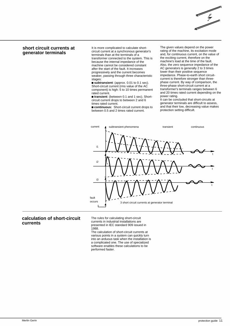
It is more complicated to calculate short-circuit current at a synchronous generator'sterminals than at the terminals of atransformer connected to the system. This isbecause the internal impedance of themachine cannot be considered constantafter the start of the fault. It increasesprogressively and the current becomesweaker, passing through three characteristicstages:
subtransient: (approx. 0.01 to 0.1 sec).Short-circuit current (rms value of the ACcomponent) is high: 5 to 10 times permanentrated current.
transient: (between 0.1 and 1 sec). Short-circuit current drops to between 2 and 6times rated current.
continuous: Short-circuit current drops tobetween 0.5 and 2 times rated current.
short circuit currents atgenerator terminals
The given values depend on the powerrating of the machine, its excitation modeand, for continuous current, on the value ofthe exciting current, therefore on themachine's load at the time of the fault.Also, the zero sequence impedance of theAC generators is generally 2 to 3 timeslower than their positive sequenceimpedance. Phase-to-earth short circuit-current is therefore stronger than three-phase current. By way of comparison, thethree-phase short-circuit current at atransformer's terminals ranges between 6and 20 times rated current depending on thepower rating.It can be concluded that short-circuits atgenerator terminals are difficult to assess,and that their low, decreasing value makesprotection setting difficult.
calculation of short-circuitcurrents
The rules for calculating short-circuitcurrents in industrial installations arepresented in IEC standard 909 issued in1988.The calculation of short-circuit currents atvarious points in a system can quickly turninto an arduous task when the installation isa complicated one. The use of specializedsoftware enables these calculations to beperformed faster.
3 short circuit currents at generator terminal
faultoccurs
i2
t
i3
t
t
i1
transient continuoussubtransient phenomenacurrent
12 protection guide Merlin Gerin
short-circuit currents (cont.)
equipment behaviourduring short-circuits
There are 2 types of system equipment, thetype that intervenes and the type that doesnot intervene at the time of a fault.
Passive equipmentThis category comprises all equipmentwhich, due to its function, must have thecapacity to transport both normal currentand short-circuit current without damage.
This equipment includes cables, lines,busbars, disconnecting switches, switches,transformers, series reactances andcapacitors, instrument transformers.For this equipment, the capacity to withstanda short-circuit without damage is defined interms of:
electrodynamic withstand (expressed inpeak kA), characterizing mechanicalresistance to electrodynamic stress.
thermal withstand (expressed in rms kA for1 to 5 seconds) characterizing maximumadmitted overheating.
Active equipmentThis category comprises the equipmentdesigned to clear short circuit currents:circuit breakers and fuses.This property is expressed by the breakingcapacity and if required, by the makingcapacity upon occurrence of a fault.
breaking capacityThis basic characteristic of a switchingdevice is the maximum current (in rms kA)it is capable of breaking in the specificconditions defined by the standards, itgenerally refers to the rms value of the ACcomponent of the short circuit current;sometimes, for certain switchgear, the rmsvalue of the sum of the 2 components isspecified: AC and DC; it is then "unbalancedcurrent".The breaking capacity requires other datasuch as:
voltage,R/X ratio of broken circuit,system natural frequency,number of breaks at maximum current,
for example the cycle: B - M/B - M/B(B = breaking; M = making),
status of the device after test.The breaking capacity appears to be a fairlycomplicated characteristic to define:it therefore comes as no surprise that thesame device can be assigned differentbreaking capacities depending on thestandard by which it is defined.
making capacity upon occurrenceof a short-circuitIn general, this characteristic is implicitlydefined by the breaking capacity: a deviceshould have the capacity to "make" upon theoccurrence of a short-circuit that it has thecapacity to break.Sometimes making capacity needs to behigher, for example for AC generator circuitbreakers.The making capacity is defined at peak kAsince the 1st asymmetric peak is the mostrestrictive one from an electrodynamic pointof view.
short-circuit current presumed to be"broken"Some devices have the capacity to limit thecurrent they are going to break.Their breaking capacity is defined as themaximum current presumed to be brokenthat would develop in the case of a full shortcircuit at the upstream terminals of thedevice.

Merlin Gerin protection guide 13
14 protection guide Merlin Gerin
I >
I >
I >
Merlin Gerin protection guide 15
introduction Various means can be implemented toensure proper discrimination in electricalsystem protection:c current discrimination,c time discrimination,c discrimination by data exchange, referredto as logic discrimination,c discrimination by the use of directionalprotection devices,c discrimination by the use of differentialprotection devices.
Protections comprise a coherent whole inrelation to the structure of the system and itsgrounding. They should be looked upon as asystem based on the principle ofdiscrimination which consists of isolating asquickly as possible the part of the systemaffected by the fault and only that part,leaving all the fault-free parts of the systemenergized.
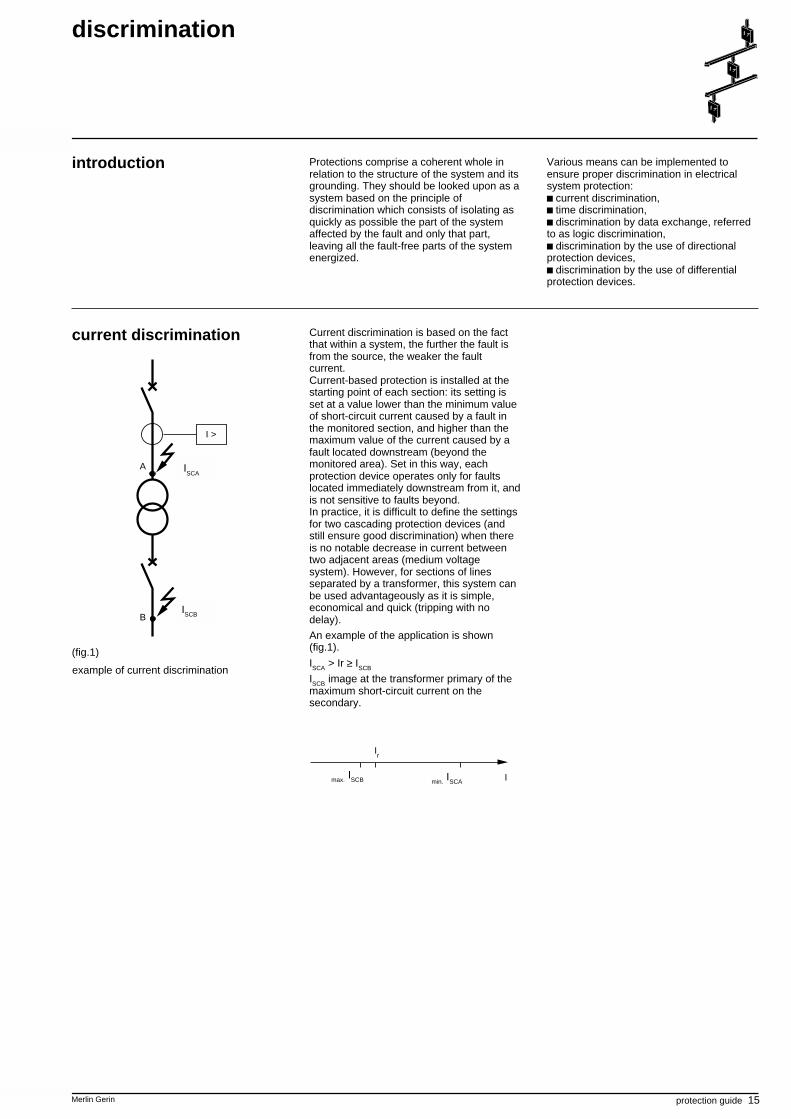
current discrimination
(fig.1)
example of current discrimination
Icc A
I >
Icc B
A
B
Current discrimination is based on the factthat within a system, the further the fault isfrom the source, the weaker the faultcurrent.Current-based protection is installed at thestarting point of each section: its setting isset at a value lower than the minimum valueof short-circuit current caused by a fault inthe monitored section, and higher than themaximum value of the current caused by afault located downstream (beyond themonitored area). Set in this way, eachprotection device operates only for faultslocated immediately downstream from it, andis not sensitive to faults beyond.In practice, it is difficult to define the settingsfor two cascading protection devices (andstill ensure good discrimination) when thereis no notable decrease in current betweentwo adjacent areas (medium voltagesystem). However, for sections of linesseparated by a transformer, this system canbe used advantageously as it is simple,economical and quick (tripping with nodelay).
An example of the application is shown(fig.1).
ISCA > Ir ≥ ISCB
ISCB image at the transformer primary of themaximum short-circuit current on thesecondary.
I
Ir
min. ISCAmax. ISCB
ISCB
ISCA
discrimination
16 protection guide Merlin Gerin
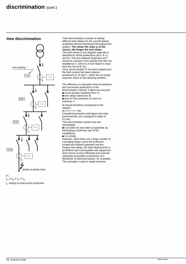
time discrimination Time discrimination consists of settingdifferent time delays for the current-basedprotection devices distributed throughout thesystem. The closer the relay is to thesource, the longer the time delay.The fault shown in the diagram opposite isdetected by all the protections (at A, B, C,and D). The time-delayed protection at Dcloses its contacts more quickly than the oneinstalled at C, which is in turn faster to reactthan the one at B, etc.Once circuit breaker D has been tripped andthe fault current has been cleared,protections A, B and C, which are no longerrequired, return to the stand-by position.
The difference in operation times ∆t betweentwo successive protections is thediscrimination interval. It takes into account:c circuit breaker breaking time Tc,c time delay tolerances dt,c time for the protection to return tostand-by: tr
∆t should therefore correspond to therelation:∆t ≥ Tc + tr + 2dt.Considering present switchgear and relayperformances, ∆t is assigned a value of0.3 sec.This discrimination system has twoadvantages:c it provides its own back-up (granted, byeliminating a fault-free part of theinstallation),c it is simple.However, when there are a large number ofcascading relays, since the protectionlocated the furthest upstream has thelongest time delay, the fault clearing time isprohibitive and incompatible with equipmentshort-circuit current withstand and externaloperating necessities (connection of adistributor to electrical system, for example).This principle is used in radial networks.
(*)IRA ≥ IRB ≥ IRC ≥ IRD
IR: setting of overcurrent protection
time setting *
phase to phase fault
0,2s
D
I >
0,5s
C
I >
0,8s
B
I >
1,1s
AI >
discrimination (cont.)
I >
I >
I >
Merlin Gerin protection guide 17
t
I
C B A
∆t
∆t
IrC
IrB
IrA
tA
tB
tC
IccC
IccB
IccA
t
I
t
I
C B A
∆t
∆t
IrC
IrB
IrA
IccC
IccB
IccA
t
I
B
IrC
IrB
IrA
A
C
application of timediscrimination
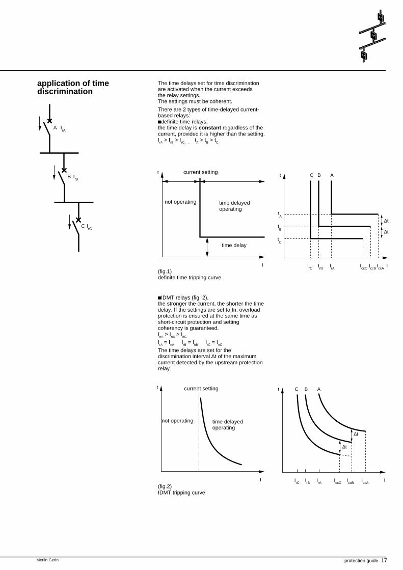
The time delays set for time discriminationare activated when the current exceedsthe relay settings.The settings must be coherent.
There are 2 types of time-delayed current-based relays:cdefinite time relays,the time delay is constant regardless of thecurrent, provided it is higher than the setting.IrA > IrB > IrC. , tA > tB > tC.
cIDMT relays (fig. 2),the stronger the current, the shorter the timedelay. If the settings are set to In, overloadprotection is ensured at the same time asshort-circuit protection and settingcoherency is guaranteed.InA > InB > InC
IrA = InA IrB = InB IrC = InC
The time delays are set for thediscrimination interval ∆t of the maximumcurrent detected by the upstream protectionrelay.
(fig.1)definite time tripping curve
current setting
time delayedoperating
time delay
current setting
not operating time delayedoperating
(fig.2)IDMT tripping curve
not operating
18 protection guide Merlin Gerin
discrimination (cont.)
logic selectivity
blocking input
phase-to-phase fault
logic selectivity system
R
I >
I >
R
I >
R
I >
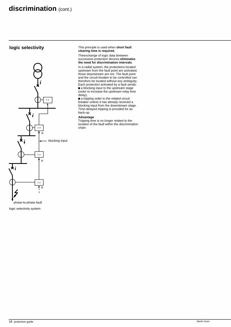
This principle is used when short faultclearing time is required.
Theexchange of logic data betweensuccessive protection devices eliminatesthe need for discrimination intervals.
In a radial system, the protections locatedupstream from the fault point are activated;those downstream are not. The fault pointand the circuit breaker to be controlled cantherefore be located without any ambiguity.Each protection activated by a fault sends:
a blocking input to the upstream stage(order to increase the upstream relay timedelay),
a tripping order to the related circuitbreaker unless it has already received ablocking input from the downstream stage.Time-delayed tripping is provided for asback-up.
AdvantageTripping time is no longer related to thelocation of the fault within the discriminationchain.
I >
I >
I >
Merlin Gerin protection guide 19
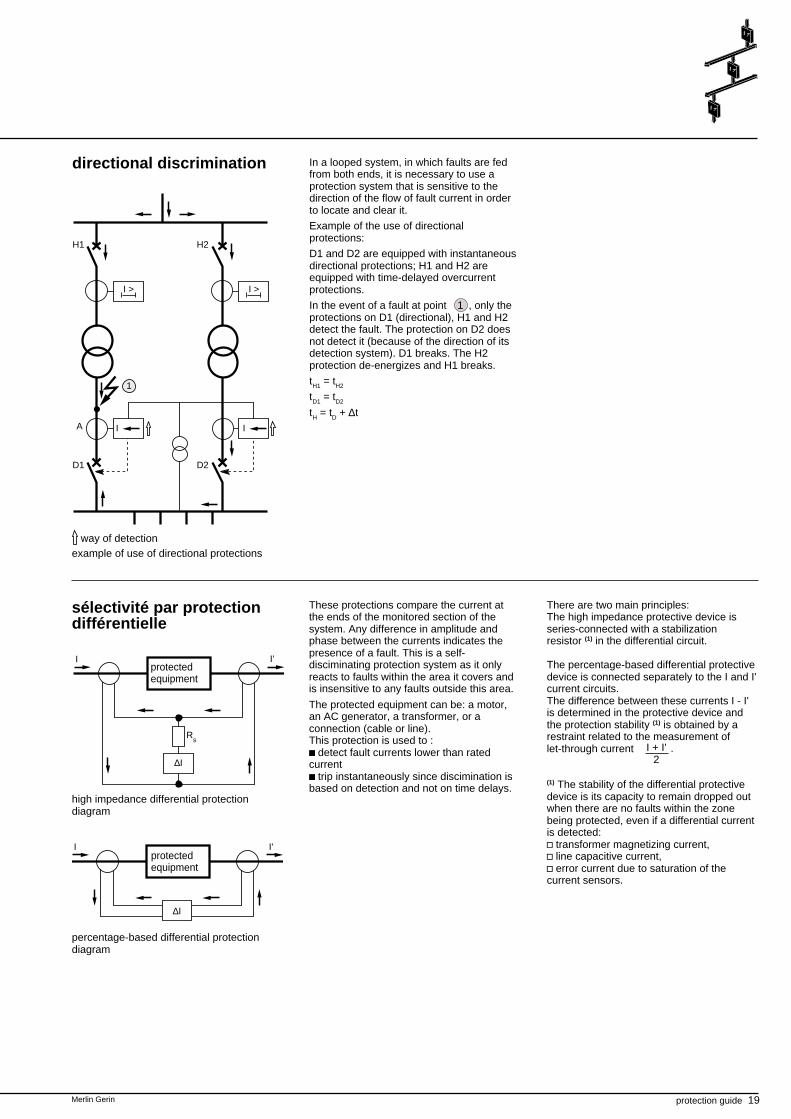
In a looped system, in which faults are fedfrom both ends, it is necessary to use aprotection system that is sensitive to thedirection of the flow of fault current in orderto locate and clear it.
Example of the use of directionalprotections:
D1 and D2 are equipped with instantaneousdirectional protections; H1 and H2 areequipped with time-delayed overcurrentprotections.
In the event of a fault at point 1 , only theprotections on D1 (directional), H1 and H2detect the fault. The protection on D2 doesnot detect it (because of the direction of itsdetection system). D1 breaks. The H2protection de-energizes and H1 breaks.
tH1 = tH2
tD1 = tD2
tH = tD + ∆t
directional discrimination
I > I >
1
IA
H2H1
D2D1
I
example of use of directional protectionsway of detection
I
∆I
Rs
I'
sélectivité par protectiondifférentielle
These protections compare the current atthe ends of the monitored section of thesystem. Any difference in amplitude andphase between the currents indicates thepresence of a fault. This is a self-disciminating protection system as it onlyreacts to faults within the area it covers andis insensitive to any faults outside this area.
The protected equipment can be: a motor,an AC generator, a transformer, or aconnection (cable or line).This protection is used to :c detect fault currents lower than ratedcurrentc trip instantaneously since discimination isbased on detection and not on time delays.
There are two main principles:The high impedance protective device isseries-connected with a stabilizationresistor (1) in the differential circuit.
The percentage-based differential protectivedevice is connected separately to the I and I'current circuits.The difference between these currents I - I'is determined in the protective device andthe protection stability (1) is obtained by arestraint related to the measurement oflet-through current
(1) The stability of the differential protectivedevice is its capacity to remain dropped outwhen there are no faults within the zonebeing protected, even if a differential currentis detected:v transformer magnetizing current,v line capacitive current,v error current due to saturation of thecurrent sensors.
protectedequipment
high impedance differential protectiondiagram
I I'
∆I
percentage-based differential protectiondiagram
protectedequipment
.I + I'2
20 protection guide Merlin Gerin
Merlin Gerin protection guide 21
electrical system protection
introduction Electrical system protection should: detect faults, cut off of the faulty parts of the electrical
system, keeping the fault-free parts inoperation.
Protection systems are chosen according tothe electrical system configuration (paralleloperation of AC generators or transformers,loop or radial system,grounding system…).
Protection against each of the followingtypes of faults is to be considered:
phase-to-phase faults, earth faults (protections related to
electrical system grounding).This will be done by successively examiningthe following cases:
a single incoming line, two incoming lines, a busbar, a loop.
22 protection guide Merlin Gerin
electrical system protection (cont.)
electrical system witha single incoming line
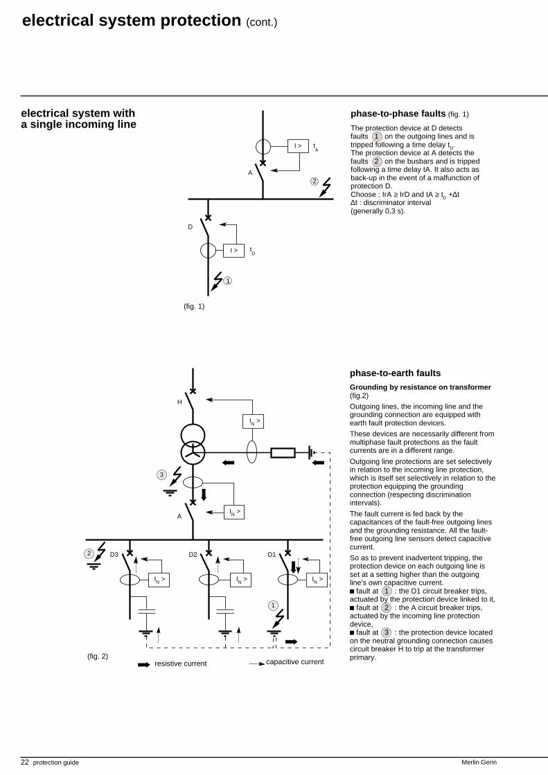
phase-to-phase faults (fig. 1)
The protection device at D detectsfaults 1 on the outgoing lines and istripped following a time delay tD.The protection device at A detects thefaults 2 on the busbars and is trippedfollowing a time delay tA. It also acts asback-up in the event of a malfunction ofprotection D.Choose : IrA ≥ IrD and tA ≥ tD +∆t∆t : discriminator interval(generally 0,3 s).
D
I >
A
1
2
I > tA
tD
(fig. 1)
phase-to-earth faultsGrounding by resistance on transformer(fig.2)
Outgoing lines, the incoming line and thegrounding connection are equipped withearth fault protection devices.
These devices are necessarily different frommultiphase fault protections as the faultcurrents are in a different range.
Outgoing line protections are set selectivelyin relation to the incoming line protection,which is itself set selectively in relation to theprotection equipping the groundingconnection (respecting discriminationintervals).
The fault current is fed back by thecapacitances of the fault-free outgoing linesand the grounding resistance. All the fault-free outgoing line sensors detect capacitivecurrent.
So as to prevent inadvertent tripping, theprotection device on each outgoing line isset at a setting higher than the outgoingline's own capacitive current.c fault at 1 : the D1 circuit breaker trips,actuated by the protection device linked to it,c fault at 2 : the A circuit breaker trips,actuated by the incoming line protectiondevice,c fault at 3 : the protection device locatedon the neutral grounding connection causescircuit breaker H to trip at the transformerprimary.(fig. 2)
2
A
D2
H
D3 D1
I >N
I >N
I >NI >NI >N
1
3
resistive current capacitive current
Merlin Gerin protection guide 23
A
D1
H
3
D2
1
IrD
tD
IrA
tA
I >N
I >NI >N
2
IrN
tN
I >N
(fig. 3)
(fig. 4)
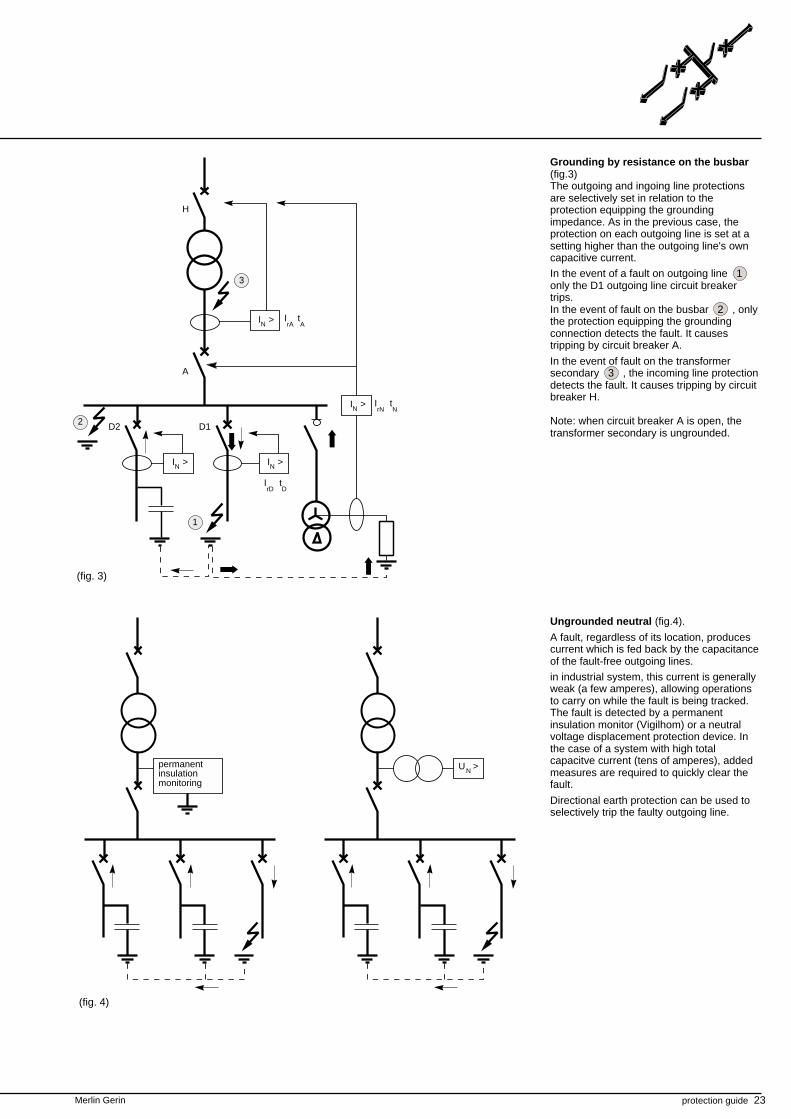
Grounding by resistance on the busbar(fig.3)The outgoing and ingoing line protectionsare selectively set in relation to theprotection equipping the groundingimpedance. As in the previous case, theprotection on each outgoing line is set at asetting higher than the outgoing line's owncapacitive current.
In the event of a fault on outgoing line 1only the D1 outgoing line circuit breakertrips.In the event of fault on the busbar 2 , onlythe protection equipping the groundingconnection detects the fault. It causestripping by circuit breaker A.
In the event of fault on the transformersecondary 3 , the incoming line protectiondetects the fault. It causes tripping by circuitbreaker H.
Note: when circuit breaker A is open, thetransformer secondary is ungrounded.
Ungrounded neutral (fig.4).
A fault, regardless of its location, producescurrent which is fed back by the capacitanceof the fault-free outgoing lines.
in industrial system, this current is generallyweak (a few amperes), allowing operationsto carry on while the fault is being tracked.The fault is detected by a permanentinsulation monitor (Vigilhom) or a neutralvoltage displacement protection device. Inthe case of a system with high totalcapacitve current (tens of amperes), addedmeasures are required to quickly clear thefault.
Directional earth protection can be used toselectively trip the faulty outgoing line.
U >Npermanentinsulationmonitoring
24 protection guide Merlin Gerin
electrical system protection (cont.)
system with two incominglines
A1
H1
3
1
D1 D2
A2
H2
D3
I >N
I >N
IN
I >N
I >NI >N
2
tN
tN
INtR
tR
tD
tD
tD
(fig. 2)
detection way
3
2
I
A1 A2
T1 T2
I >
H1 H2
I > tH
tH
tR
tA
tD
D2
tD
I >
I
I >
tR
tA
D1
1
I > I >
(fig. 1)
detection way
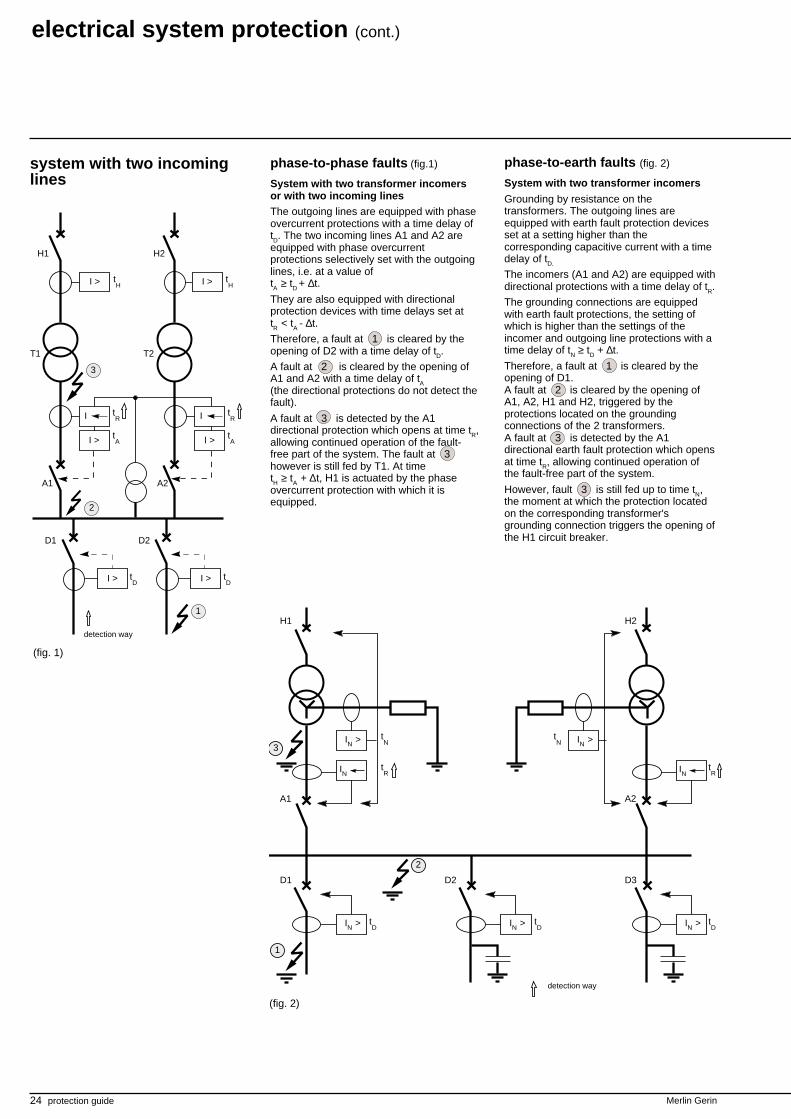
phase-to-phase faults (fig.1)
System with two transformer incomersor with two incoming linesThe outgoing lines are equipped with phaseovercurrent protections with a time delay oftD. The two incoming lines A1 and A2 areequipped with phase overcurrentprotections selectively set with the outgoinglines, i.e. at a value oftA ≥ tD + ∆t.
They are also equipped with directionalprotection devices with time delays set attR < tA - ∆t.
Therefore, a fault at 1 is cleared by theopening of D2 with a time delay of tD.
A fault at 2 is cleared by the opening ofA1 and A2 with a time delay of tA(the directional protections do not detect thefault).
A fault at 3 is detected by the A1directional protection which opens at time tR,allowing continued operation of the fault-free part of the system. The fault at 3however is still fed by T1. At timetH ≥ tA + ∆t, H1 is actuated by the phaseovercurrent protection with which it isequipped.
phase-to-earth faults (fig. 2)
System with two transformer incomers
Grounding by resistance on thetransformers. The outgoing lines areequipped with earth fault protection devicesset at a setting higher than thecorresponding capacitive current with a timedelay of tD.
The incomers (A1 and A2) are equipped withdirectional protections with a time delay of tR.
The grounding connections are equippedwith earth fault protections, the setting ofwhich is higher than the settings of theincomer and outgoing line protections with atime delay of tN ≥ tD + ∆t.
Therefore, a fault at 1 is cleared by theopening of D1.A fault at 2 is cleared by the opening ofA1, A2, H1 and H2, triggered by theprotections located on the groundingconnections of the 2 transformers.A fault at 3 is detected by the A1directional earth fault protection which opensat time tR, allowing continued operation ofthe fault-free part of the system.
However, fault 3 is still fed up to time tN,the moment at which the protection locatedon the corresponding transformer'sgrounding connection triggers the opening ofthe H1 circuit breaker.
Merlin Gerin protection guide 25
busbars
∆I
A
D1
D2
1
2
t = 0,1 s
t = 0,6 s
t = 0,3 s
I >
I >
I >
(fig. 4)
(fig. 3)
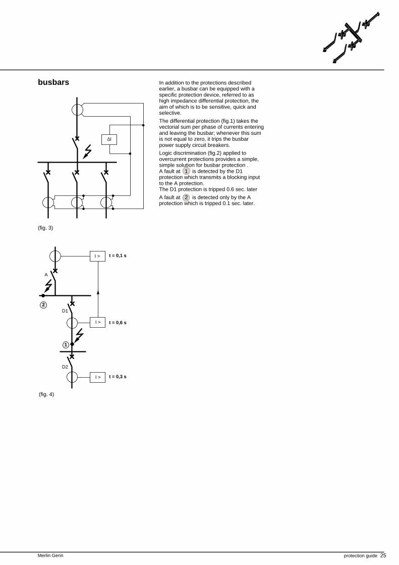
In addition to the protections describedearlier, a busbar can be equipped with aspecific protection device, referred to ashigh impedance differential protection, theaim of which is to be sensitive, quick andselective.
The differential protection (fig.1) takes thevectorial sum per phase of currents enteringand leaving the busbar; whenever this sumis not equal to zero, it trips the busbarpower supply circuit breakers.
Logic discrimination (fig.2) applied toovercurrent protections provides a simple,simple solution for busbar protection .A fault at 1 is detected by the D1protection which transmits a blocking inputto the A protection.The D1 protection is tripped 0.6 sec. later
A fault at 2 is detected only by the Aprotection which is tripped 0.1 sec. later.
26 protection guide Merlin Gerin
electrical system protection (cont.)
open loopclosed loop
I > I >
(fig. 1)
∆I ∆I
∆I ∆I
(fig. 2)
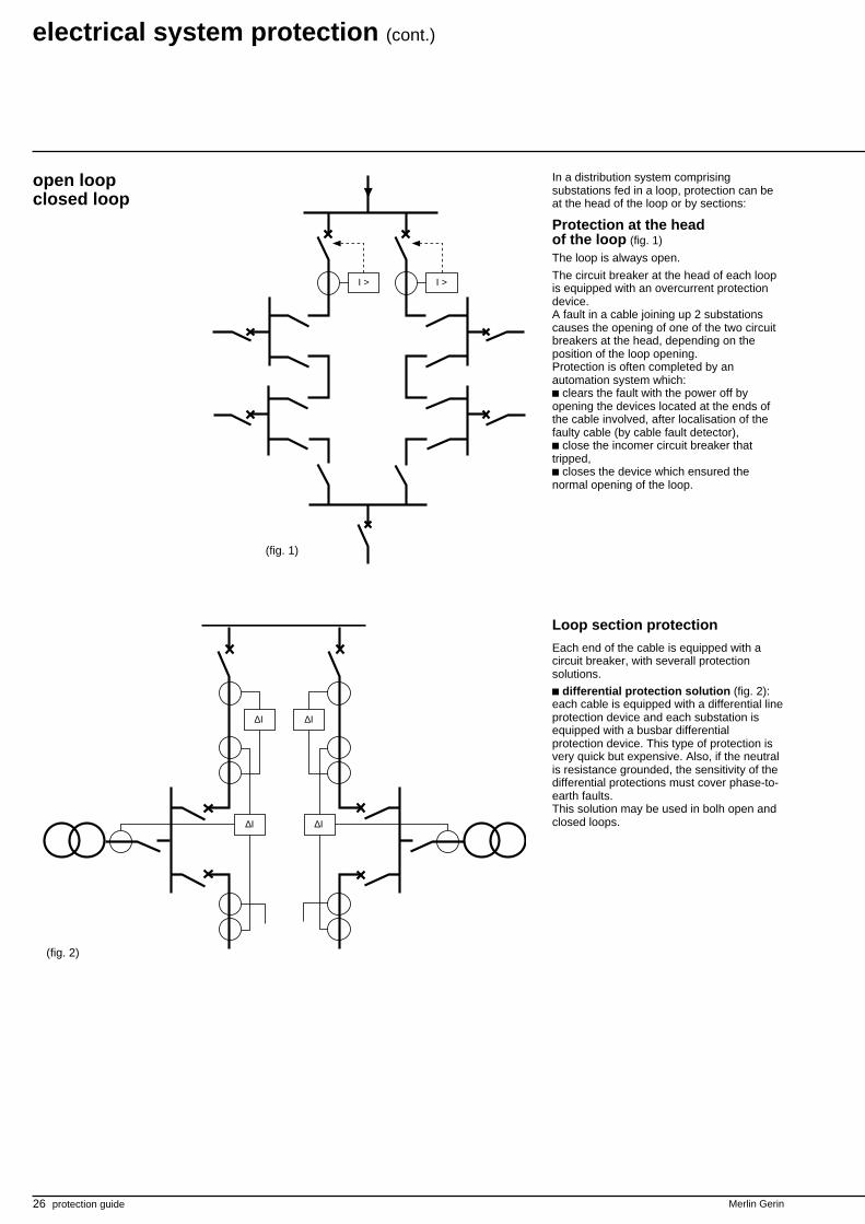
In a distribution system comprisingsubstations fed in a loop, protection can beat the head of the loop or by sections:
Protection at the headof the loop (fig. 1)
The loop is always open.
The circuit breaker at the head of each loopis equipped with an overcurrent protectiondevice.A fault in a cable joining up 2 substationscauses the opening of one of the two circuitbreakers at the head, depending on theposition of the loop opening.Protection is often completed by anautomation system which:c clears the fault with the power off byopening the devices located at the ends ofthe cable involved, after localisation of thefaulty cable (by cable fault detector),c close the incomer circuit breaker thattripped,c closes the device which ensured thenormal opening of the loop.
Loop section protection
Each end of the cable is equipped with acircuit breaker, with severall protectionsolutions.
c differential protection solution (fig. 2):each cable is equipped with a differential lineprotection device and each substation isequipped with a busbar differentialprotection device. This type of protection isvery quick but expensive. Also, if the neutralis resistance grounded, the sensitivity of thedifferential protections must cover phase-to-earth faults.This solution may be used in bolh open andclosed loops.
Merlin Gerin protection guide 27
I >
I >
I I >
I >
t5
t4 t1t4 t1
I >
t3 t2
I >
t3 t2
t5
I I I
(fig. 3)
(fig. 4)
time gap between t1, t2,… t3 is ∆t discrimination interval detection way
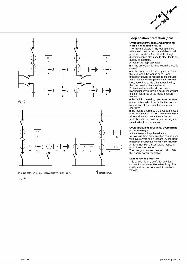
Loop section protection (cont.)
Overcurrent protection and directionallogic discrimination (fig. 3)The circuit breakers in the loop are fittedwith overcurrent protection and directionalprotection devices. The principle of logicdiscrimination is also used to clear faults asquickly as possible.A fault in the loop activates:c all the protection devices when the loop isclosed,c all the protection devices upstream fromthe fault when the loop is open. Eachprotection device sends a blocking input toone of the devices adjacent to it within theloop, according to the data transmitted bythe directional protection device.Protection devices that do not receive ablocking input trip within a minimum amountof time regardless of the fault's position inthe loop:c the fault is cleared by two circuit breakers,one on either side of the fault if the loop isclosed, and all the switchboards remainenergized,c the fault is cleared by the upstream circuitbreaker if the loop is open. This solution is afull one since it protects the cables andswitchboards. It is quick, discriminating andincludes back-up protection.
Overcurrent and directional overcurrentprotection (fig. 4)In the case of a loop limited to twosubstations, time discrimination can be usedwith overcurrent and directional overcurrentprotection devices as shown in the diagram.A higher number of substations results inprohibitive time delays.The time gap between delays t1, t2… t5 isthe discrimination interval ∆t.
Long distance protectionThis solution is only useful for very longconnections (several kilometers long). It iscostly and very seldom used, in mediumvoltage.
I >
I
I
I
I
I >
I
I
I
I
28 protection guide Merlin Gerin
Merlin Gerin protection guide 29
introduction
transformer protection
types of faults The main faults affecting transformers are:c overloads,c short-circuits,c frame faults
An overload can result from an increase inthe number of loads being fedsimultaneously or from an increase in thepower absorbed by one or more loads.It results in an overcurrrent of long durationcausing a rise in temperature that isdetrimental to the preservation of insulationand to the service life of the transformer.
Short circuits can be inside or outside thetransformer:c internal: faults occurring between windingconductors with different phases or faults inthe same winding. The fault arc damagesthe transformer winding and can cause fire.In oil transformers, the arc causes theemission of decomposition gas. If the fault isa weak one, there is a slight gas emissionand the accumulation of gas can becomedangerous. A violent short circuit can causemajor damage that can destroy the windingand also the tank frame by the spread ofburning oil.
c external: phase-to-phase faults in thedownstream connections. The downstreamshort circuit current produceselectrodynamic forces In the transformer thatare liable to affect the windings mechanicallyand then develop in the form of internalfaults.
A frame fault is an internal fault. It canoccur between the winding and the tankframe or between the winding and themagnetic core. It causes gas emission in oiltransformers. Like internal short circuits, itcan cause transformer damage and fire.
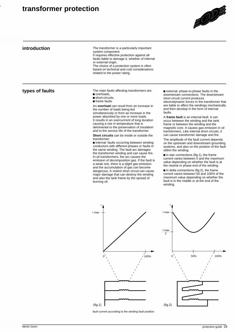
The amplitude of the fault current dependson the upstream and downstream groundingsystems, and also on the position of the faultwithin the winding.
c in star connections (fig.1), the framecurrent varies between 0 and the maximumvalue depending on whether the fault is atthe neutral or phase end of the winding.
c in delta connections (fig.2), the framecurrent varies between 50 and 100% of themaximum value depending on whether thefault is in the middle or at the end of thewinding.
I
100%0
I
100%50%0
I max I max
I max 2
(fig.1) (fig.2)
fault current according to the winding fault position
The transformer is a particularly importantsystem component.It requires effective protection against allfaults liable to damage it, whether of internalor external origin.The choice of a protection system is oftenbased on technical and cost considerationsrelated to the power rating.

30 protection guide Merlin Gerin
protection devices
transformer protection (cont.)
I >
I >>∆I
(fig.1)
(fig.3)
I >
IN
>
(fig.5)
∆I
OverloadsOvercurrent of long duration is generallydetected by a direct time or IDMT delayedovercurrent protection which isdiscriminating with respect to secondaryprotection.
Thermal overload protection is used tomonitor the temperature rise: overheating isdetermined by simulation of heat release asa function of the current and temperature lagof the transformer.
Short-circuitsFor oil transformers:c a Buchholz relay or DGPT gas pressuretemperature detector that is sensitive to gasrelease or oil movement is used, causingrespectively a short-circuit between turns ofthe same phase and a violent phase-to-phase short-circuit.c differential transformer protection (fig.1)ensures rapid protection against phase-to-phase faults. It is sensitive to fault currentsin the range of 0.5 In and is used forimportant transformers.c an instantaneous overcurrent protection(fig.2) device linked to the circuit breakerlocated at the transformer primary ensuresprotection against violent short circuits. Thecurrent setting is set at a value higher thanthe current due to a short circuit on thesecondary, thus ensuring currentdiscrimination.c for low power transformers, a fuse is usedfor overcurrent protection.
Tank frame faultsc tank frame protection (fig.3):This instantaneous overcurrent protectiondevice installed on the transformer frameearthing connection constitutes a simple,efficient solution for internal winding-to-frame faults (provided its setting is suitablewith grounding system used) the transformertank has to be insulated from the ground.
This form of protection is discriminating,being sensitive only to transformer framefaults.
Another solution consists of using earth faultprotection:c earth protection located on the upstreamsystem for frame faults affecting thetransformer primary.c earth fault protection located on theincoming line of the board being fed, if theneutral of the downstream system is earthedon the busbars (fig.4).These protections are disciminating: theyare only sensitive to phase-to-earth faultslocated in the transformer or on theupstream and downstream connections.c restricted earth protection if the neutral ofthe downstream system is earthed at thetransformer (fig.5). This is a high impedancedifferential protection system which detectsthe difference in residual currents measuredat the grounding point and at the three-phase transformer outlet.c neutral earth protection if the downstreamsystem is earthed at the transformer (fig.6).
(fig.2)
(fig.4)
IN
>
(fig.6)
Merlin Gerin protection guide 31
IN
>
I>
I>>
IN>
(2)
(3)
(4)
(5)(6)
(2)
(6)
I (1)
(4)
IN
> (3)
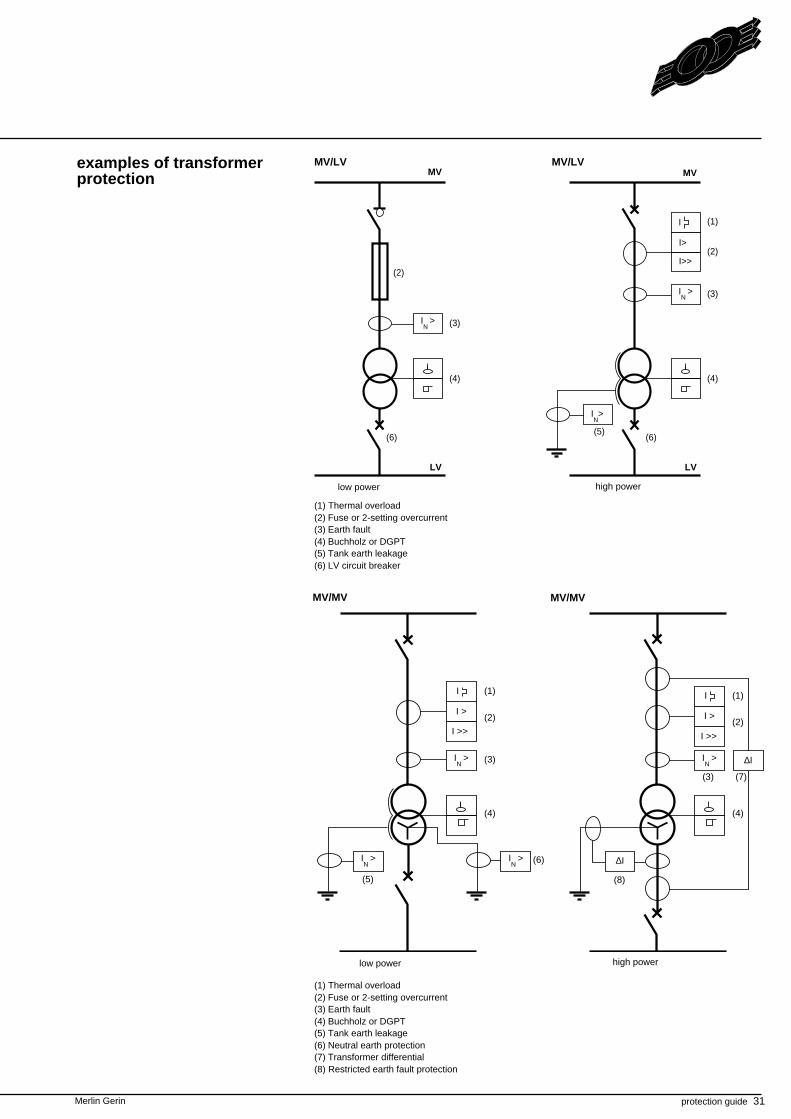
examples of transformerprotection
MV/LVMV/LV
(1) Thermal overload(2) Fuse or 2-setting overcurrent(3) Earth fault(4) Buchholz or DGPT(5) Tank earth leakage(6) Neutral earth protection(7) Transformer differential(8) Restricted earth fault protection
(1) Thermal overload(2) Fuse or 2-setting overcurrent(3) Earth fault(4) Buchholz or DGPT(5) Tank earth leakage(6) LV circuit breaker
high powerlow power
low power high power
LV
MV MV
LV
MV/MVMV/MV
∆I
I >>
IN
>
(7)
(8)
(1)
(2)
(3)
(4)
(5)
IN
>
I >
I
(4)
I >>
(1)
(2)I >
I
(3)
IN
>
(6)IN
>
∆I
I >>I >>
32 protection guide Merlin Gerin
transformer protection (cont.)
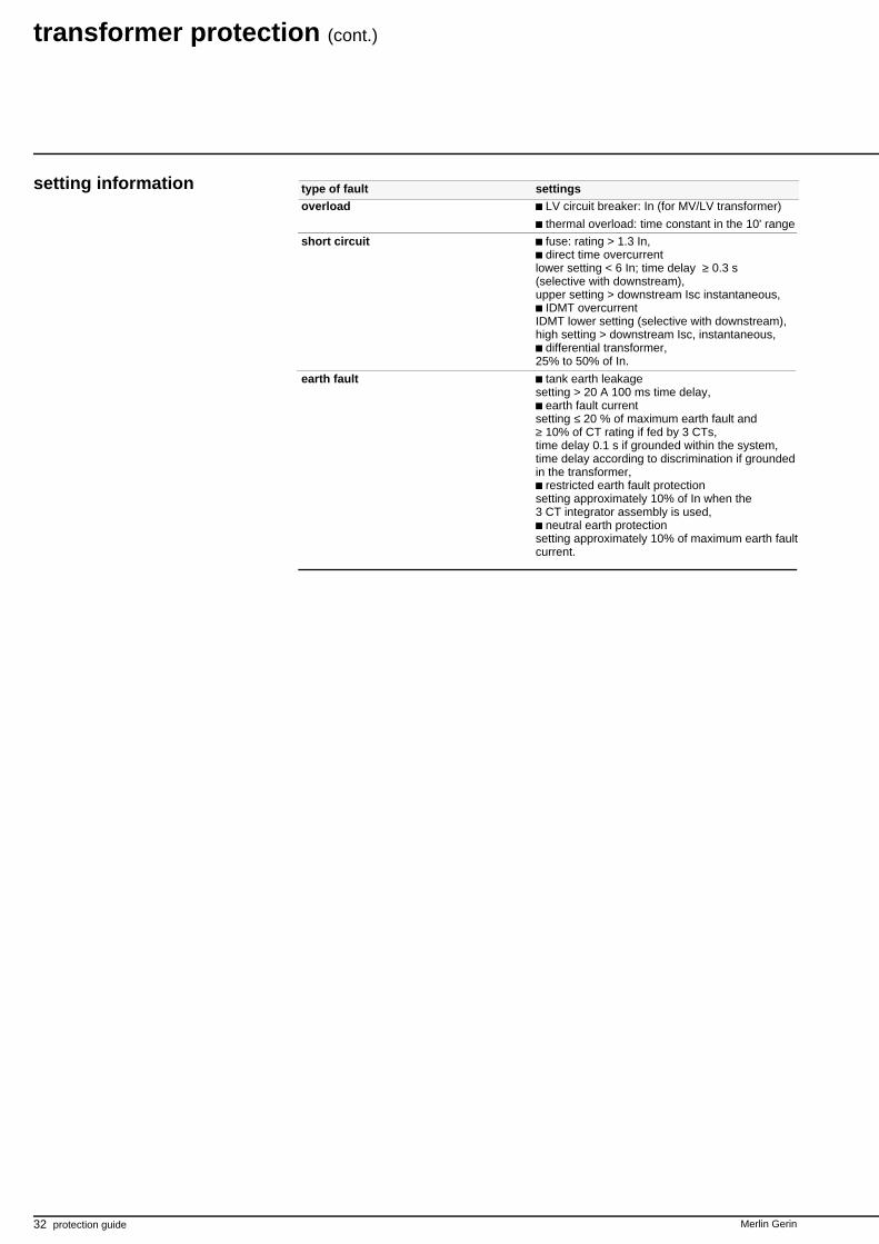
setting information type of fault settingsoverload LV circuit breaker: In (for MV/LV transformer)
thermal overload: time constant in the 10' range
short circuit fuse: rating > 1.3 In,direct time overcurrent
lower setting < 6 In; time delay ≥ 0.3 s(selective with downstream),upper setting > downstream Isc instantaneous,
IDMT overcurrentIDMT lower setting (selective with downstream),high setting > downstream Isc, instantaneous,
differential transformer,25% to 50% of In.
earth fault tank earth leakagesetting > 20 A 100 ms time delay,
earth fault currentsetting ≤ 20 % of maximum earth fault and≥ 10% of CT rating if fed by 3 CTs,time delay 0.1 s if grounded within the system,time delay according to discrimination if groundedin the transformer,
restricted earth fault protectionsetting approximately 10% of In when the3 CT integrator assembly is used,
neutral earth protectionsetting approximately 10% of maximum earth faultcurrent.
Merlin Gerin protection guide 33
34 protection guide Merlin Gerin
Merlin Gerin protection guide 35
The motor constitutes an interface betweenthe electrical and mechanical fields.It is found in an environment linked to thedriven load, from which it is inseparable.
Furthermore, the motor can be subjected toinner mechanical stress due to its movingparts.
A single faulty motor may cause disturbancein a complete production process.
motor protection
Modern motors have optimizedcharacteristics which make theminappropriate for operation other thanaccording to their rated characteristics.
The motor is therefore a relatively fragileelectrical load that needs to be carefullyprotected.
introduction
types of faults Motors are affected by:faults related to the driven loadpower supply faultsinternal motor faults
Faults related to the driven load overloads. Since the power called upon is
greater than rated power, there isovercurrent in the motor and an increase inlosses, causing a rise in temperature.
too long, too frequent start-ups. Motorstart-up creates substantial overcurrentswhich are only admissible since they are ofshort duration. If start-ups are too frequentor too long due to an insufficient gapbetween motor torque and load torque, theoverheating that is inevitably producedbecomes prohibitive.
jamming. This refers to a sudden stop inrotation for any reason related to the drivenmechanism. The motor absorbs the start-upcurrent and stays jammed at zero speed.There is no more ventilation and overheatingvery quickly occurs.
pump de-energizing. This causes motoridling which has no direct harmful effect.However, the pump itself quickly becomesdamaged.
reverse power. This type of fault occursdue to a voltage drop when a synchronousmotor driven by the inertia of the load sendspower back into the network. In particular,should the normal network power supply bereleased, the synchronous motor canmaintain the voltage in an undesirablefashion and feed the other loads which areconnected in parallel.
Power supply faultsdrop in voltage. This reduces motor torque
and speed: the slow-down causes increasedcurrent and losses. Abnormal overheatingtherefore occurs.
unbalance. 3-phase power supply can beunbalanced because:
the power source (transformer or ACgenerator) does not provide symmetrical3-phase voltage,
all the other consumers together do notconstitute a symmetrical load, unbalancingthe power supply network,
the motor is fed on two phases due to fusemelting.Power supply unbalance produces reversecurrrent causing very high losses andtherefore quick rotor overheating.
Internal motor faultsphase-to-phase short-circuits: these can
vary in strength depending on the position ofthe fault within the coil; they cause seriousdamage.
frame faults: fault current amplitudedepends on the power supply networkgrounding system and on the fault's positionwithin the coil. Phase-to-phase short-circuitsand frame faults require motor rewinding,and frame faults can produce irreparabledamage to the magnetic circuit.
loss of synchronism.This fault involvessynchronous motors losing theirsynchronism due to field loss: motoroperation is asynchronous but the rotorundergoes considerable overheating since itis not designed for this.
36 protection guide Merlin Gerin
motor protection (cont.)
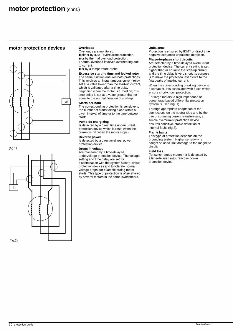
OverloadsOverloads are monitored:c either by IDMT overcurrent protection,c or by thermal overload protection.Thermal overload involves overheating dueto current.c or by a temperature probe.
Excessive starting time and locked rotorThe same function ensures both protections.This involves an instantaneous current relayset at a value lower than the start-up current,which is validated after a time delaybeginning when the motor is turned on; thistime delay is set at a value greater than orequal to the normal duration of start-up.
Starts per hourThe corresponding protection is sensitive tothe number of starts taking place within agiven interval of time or to the time betweenstarts.
Pump de-energizingIs detected by a direct time undercurrentprotection device which is reset when thecurrent is nil (when the motor stops).
Reverse powerIs detected by a directional real powerprotection device.
Drops in voltageAre monitored by a time-delayedundervoltage protection device. The voltagesetting and time delay are set fordiscrimination with the system's short-circuitprotection devices and to tolerate normalvoltage drops, for example during motorstarts. This type of protection is often sharedby several motors in the same switchboard.
motor protection devices
∆I
(fig.1)
∆I
(fig.2)
UnbalanceProtection is ensured by IDMT or direct timenegative sequence unbalance detection.
Phase-to-phase short circuitsAre detected by a time-delayed overcurrentprotection device. The current setting is sethigher than or equal to the start-up currentand the time delay is very short; its purposeis to make the protection insensitive to thefirst peaks of making current.
When the corresponding breaking device isa contactor, it is associated with fuses whichensure short-circuit protection.
For large motors, a high impedance orpercentage-based differential protectionsystem is used (fig. 1).
Through appropriate adaptation of theconnections on the neutral side and by theuse of summing current transformers, asimple overcurrent protection deviceensures sensitive, stable detection ofinternal faults (fig.2).
Frame faultsThis type of protection depends on thegrounding system. Higher sensitivity issought so as to limit damage to the magneticcircuit.
Field loss(for synchronous motors). It is detected bya time-delayed max. reactive powerprotection device.
Merlin Gerin protection guide 37
M
I U <
P <––
Q <––
Ii >
I >
IN >
∆I
M
I
U <Ii >
I >
IN >
∆I
M
I U <
Ii >
IN >
I >
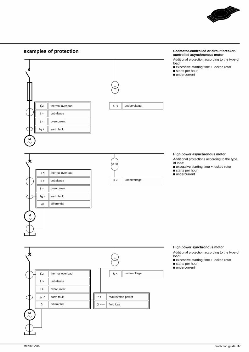
examples of protection
Additional protection according to the type ofload:c excessive starting time + locked rotorc starts per hourc undercurrent
Contactor-controlled or circuit breaker-controlled asynchronous motor
thermal overload
unbalance
overcurrent
earth fault
undervoltage
High power asynchronous motor
thermal overload
unbalance
overcurrent
earth fault
differential
undervoltage
undervoltagethermal overload
unbalance
overcurrent
earth fault
differential
real reverse power
field loss
High power synchronous motor
Additional protection according to the type ofload:c excessive starting time + locked rotorc starts per hourc undercurrent
Additional protections according to the typeof load:c excessive starting time + locked rotorc starts per hourc undercurrent
38 protection guide Merlin Gerin
motor protection (cont.)
setting information type of fault settingsoverloads thermal overload
parameters should be adapted to fit thecharacteristics of the motor (time constant inthe 10' range),
IDMT overcurrent relaysetting should allow starting.
breaking unbalance and phase reversal negative sequence unbalancesetting between 0.3 and 0.4 In,time delay: approximately 0.6 sec.If the system can function with almostcontinuous unbalance, an IDMTcharacteristic is used: setting allowing0.3 In during starting without tripping
short circuits fuserating > 1.3 In, allowing starting,
direct time overcurrentsetting ≥ 1.2 start-up current,time delay approximately 0.1 sec.differential: setting 10% to 20% of In
stator frame resistance groundingThe lowest setting compatible with theprotected outgoing line's capacitive currentis selected,setting between 10 and 20% of maximumearth fault current,time delay: 0.1 sec. approximately.
excessive starting time setting approximately 2.5 In,locked rotor time delay 1.1 x starting time.
drop in voltage setting between 0.75 and 0.8 Un,time delay: approximately 1 sec.
real reverse power approximate settingssetting 5% of Pntime delay 1 sec.
field loss approximate settingssetting 30% of Sntime delay 1 sec.
Merlin Gerin protection guide 39
40 protection guide Merlin Gerin
Merlin Gerin protection guide 41
t
AC generator operation can be altered byboth faults within the machine and bydisturbances occurring in the electricalsystem to which it is connected.An AC generator protection systemtherefore has a dual objective: protectingthe machine and protecting the system.
introduction
AC generator protection
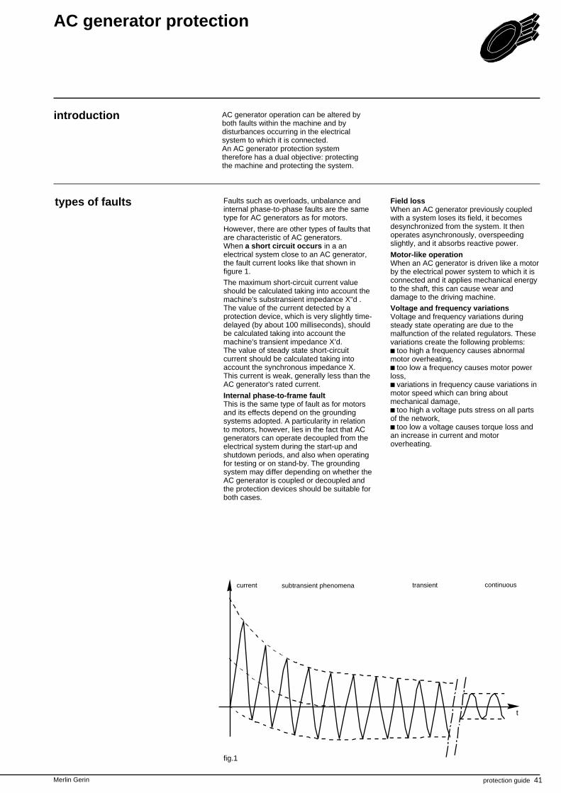
Faults such as overloads, unbalance andinternal phase-to-phase faults are the sametype for AC generators as for motors.
However, there are other types of faults thatare characteristic of AC generators.When a short circuit occurs in a anelectrical system close to an AC generator,the fault current looks like that shown infigure 1.
The maximum short-circuit current valueshould be calculated taking into account themachine's substransient impedance X"d .The value of the current detected by aprotection device, which is very slightly time-delayed (by about 100 milliseconds), shouldbe calculated taking into account themachine's transient impedance X’d.The value of steady state short-circuitcurrent should be calculated taking intoaccount the synchronous impedance X.This current is weak, generally less than theAC generator's rated current.
Internal phase-to-frame faultThis is the same type of fault as for motorsand its effects depend on the groundingsystems adopted. A particularity in relationto motors, however, lies in the fact that ACgenerators can operate decoupled from theelectrical system during the start-up andshutdown periods, and also when operatingfor testing or on stand-by. The groundingsystem may differ depending on whether theAC generator is coupled or decoupled andthe protection devices should be suitable forboth cases.
types of faults Field lossWhen an AC generator previously coupledwith a system loses its field, it becomesdesynchronized from the system. It thenoperates asynchronously, overspeedingslightly, and it absorbs reactive power.
Motor-like operationWhen an AC generator is driven like a motorby the electrical power system to which it isconnected and it applies mechanical energyto the shaft, this can cause wear anddamage to the driving machine.
Voltage and frequency variationsVoltage and frequency variations duringsteady state operating are due to themalfunction of the related regulators. Thesevariations create the following problems:
too high a frequency causes abnormalmotor overheating,
too low a frequency causes motor powerloss,
variations in frequency cause variations inmotor speed which can bring aboutmechanical damage,
too high a voltage puts stress on all partsof the network,
too low a voltage causes torque loss andan increase in current and motoroverheating.
fig.1
current subtransient phenomena continuoustransient
42 protection guide Merlin Gerin
protection devices
U
Un0,3 Un
0,3 Ir
Ir
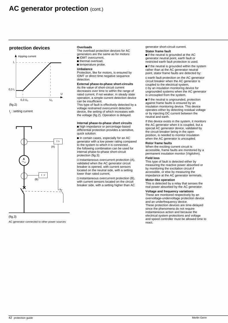
Ir : setting current
(fig.2)
A
I >
(A)
(B)
I >
(fig.3)
tripping current
AC generator connected to other power sources
AC generator protection (cont.)
generator short-circuit current.
Stator frame faultc if the neutral is grounded at the ACgenerator neutral point, earth fault orrestricted earth fault protection is used.
c if the neutral is grounded within the systemrather than at the AC generator neutralpoint, stator frame faults are detected by:
v earth fault protection on the AC generatorcircuit breaker when the AC generator iscoupled to the electrical system,v by an insulation monitoring device forungrounded systems when the AC generatoris uncoupled from the system.
c If the neutral is ungrounded, protectionagainst frame faults is ensured by aninsulation monitoring device. This deviceoperates either by detecting residual voltageor by injecting DC current between theneutral and earth.
If this device exists in the system, it monitorsthe AC generator when it is coupled, but aspecial AC generator device, validated bythe circuit breaker being in the openposition, is needed to monitor insulationwhen the AC generator is uncoupled.
Rotor frame faultsWhen the exciting current circuit isaccessible, frame faults are monitored by apermanent insulation monitor (Vigilohm).
Field lossThis type of fault is detected either bymeasuring the reactive power absorbed orby monitoring the excitation circuit ifaccessible, or else by measuring theimpedance at the AC generator terminals.
Motor-like operationThis is detected by a relay that senses thereal power absorbed by the AC generator.
Voltage and frequency variationsThese are monitored respectively by anovervoltage-undervoltage protection deviceand an underfrequency device.These protection devices are time-delayedsince the phenomena do not requireinstantaneous action and because theelectrical system protections and voltageand speed controller must be allowed time toreact.
OverloadsThe overload protection devices for ACgenerators are the same as for motors:c IDMT overcurrent,c thermal overload,c temperature probe.
UnbalanceProtection, like for motors, is ensured byIDMT or direct time negative sequencedetection.
External phase-to-phase short-circuitsAs the value of short-circuit currentdecreases over time to within the range ofrated current, if not weaker, in steady stateoperation, a simple current detection devicecan be insufficient.This type of fault is effectively detected by avoltage restrained overcurrent detectiondevice, the setting of which increases withthe voltage (fig.2). Operation is delayed.
Internal phase-to-phase short circuitsc high impedance or percentage-baseddifferential protection provides a sensitive,quick solution.
c In certain cases, especially for an ACgenerator with a low power rating comparedto the system to which it is connected ,the following combination can be used forinternal phase-to-phase short-circuitprotection (fig.3):
v instantaneous overcurrent protection (A),validated when the AC generator circuitbreaker is opened, with current sensorslocated on the neutral side, with a settinglower than rated current,
v instantaneous overcurrent protection (B),with current sensors located on the circuitbreaker side, with a setting higher than AC
Merlin Gerin protection guide 43
∆I
IN >
I
Ii >
>IU
P <––
Q <––
> U >
> f >
G
IN >
I
Ii >
>IUG
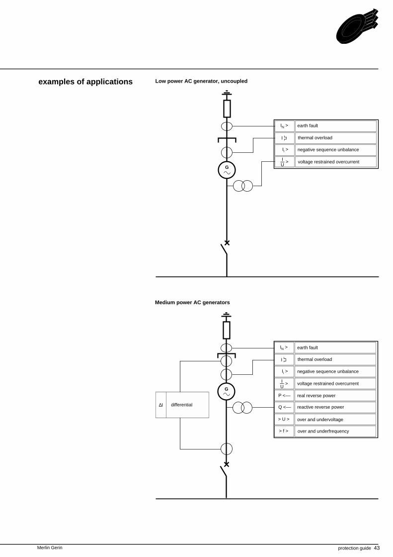
examples of applications Low power AC generator, uncoupled
earth fault
Medium power AC generators
differential
over and underfrequency
over and undervoltage
reactive reverse power
real reverse power
voltage restrained overcurrent
negative sequence unbalance
thermal overload
earth fault
negative sequence unbalance
thermal overload
voltage restrained overcurrent
44 protection guide Merlin Gerin
G
Ii >
P <––
> U >
> f >
∆I Q <––
UN >
IN >
>IU
AC generator protection (cont.)
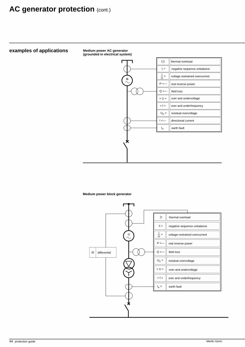
examples of applications Medium power AC generator(grounded in electrical system)
thermal overload
negative sequence unbalance
voltage restrained overcurrent
real reverse power
field loss
residual overvoltage
over and undervoltage
over and underfrequency
earth fault
differential
I
Ii >
>IU
P <––
Q <––
> U >
> f >
G
UN >
IN
I <––
negative sequence unbalance
voltage restrained overcurrent
real reverse power
field loss
over and underfrequency
residual overvoltage
over and undervoltage
directional current
earth fault
Medium power block generator
thermal overload

Merlin Gerin protection guide 45
setting information type of fault settingsoverloads thermal overload
to be adapted to rated characteristics (timeconstants in the 10' range)).
unbalance max. neg. phase sequence componentto be adapted to characteristics (if lack of data,setting 15% of In, IDMT).
external short-circuit voltage restrained overcurrentsetting 1.2 to 2 times In,time delay according to discrimination.
internal short-circuit high impedance differentialthreshold approximately 10% of In.
frame faults neutral grounded in electrical systemearth fault,setting 10% to 20% of maximum earth faultcurrent,time delay: instantaneous or 0.1 sec.
neutral grounded at AC generator neutral pointearth faultsetting approximately 10% Intime delay according to discrimination
ungroundedresidual overvoltagesetting approximately 30% of Vn
field loss reactive reverse powersetting 30% of Sn,time delay of a few seconds.
motor operation directional real powersetting 1 to 20% of Pn,time delay ≥ 1 sec.
voltage variation over and undervoltage0.8 Un < U < 1.1 Un,time delay: approximately a second.
speed variation over and underfrequency0.95 fn < f < 1.05 fn,time delay: a few seconds.
46 protection guide Merlin Gerin
Merlin Gerin protection guide 47
introduction Capacitor banks are used to compensate forreactive energy absorbed by electricalsystem loads, and sometimes to make upfilters to reduce harmonic voltage.Their role is to improve the quality of theelectrical system.They may be connected in star, delta anddouble star arrangements, depending on thelevel of voltage and the system load.
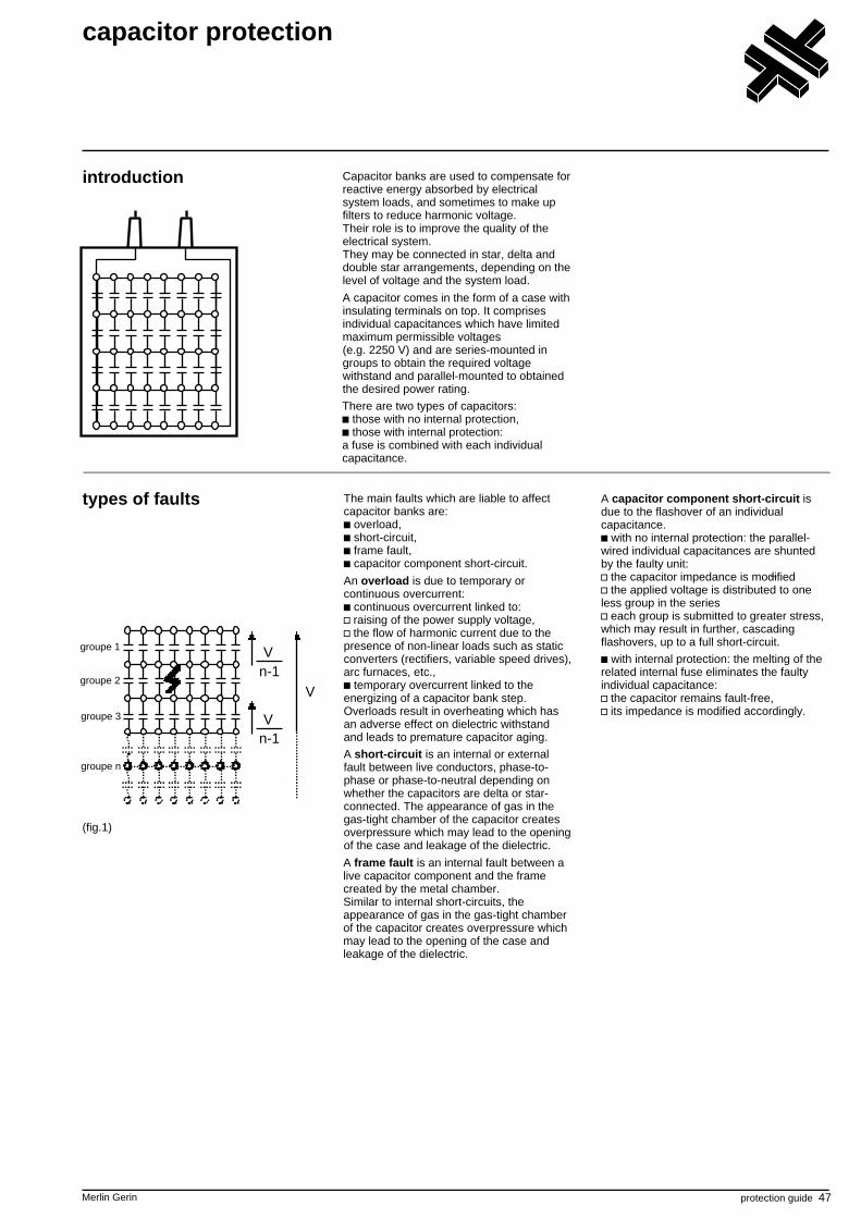
A capacitor comes in the form of a case withinsulating terminals on top. It comprisesindividual capacitances which have limitedmaximum permissible voltages(e.g. 2250 V) and are series-mounted ingroups to obtain the required voltagewithstand and parallel-mounted to obtainedthe desired power rating.
There are two types of capacitors: those with no internal protection, those with internal protection:
a fuse is combined with each individualcapacitance.
capacitor protection
types of faults The main faults which are liable to affectcapacitor banks are:
overload, short-circuit, frame fault, capacitor component short-circuit.
An overload is due to temporary orcontinuous overcurrent:
continuous overcurrent linked to: raising of the power supply voltage, the flow of harmonic current due to the
presence of non-linear loads such as staticconverters (rectifiers, variable speed drives),arc furnaces, etc.,
temporary overcurrent linked to theenergizing of a capacitor bank step.Overloads result in overheating which hasan adverse effect on dielectric withstandand leads to premature capacitor aging.
A short-circuit is an internal or externalfault between live conductors, phase-to-phase or phase-to-neutral depending onwhether the capacitors are delta or star-connected. The appearance of gas in thegas-tight chamber of the capacitor createsoverpressure which may lead to the openingof the case and leakage of the dielectric.
A frame fault is an internal fault between alive capacitor component and the framecreated by the metal chamber.Similar to internal short-circuits, theappearance of gas in the gas-tight chamberof the capacitor creates overpressure whichmay lead to the opening of the case andleakage of the dielectric.
Vn-1
Vn-1
V
groupe n
groupe 3
groupe 2
groupe 1
(fig.1)
A capacitor component short-circuit isdue to the flashover of an individualcapacitance.
with no internal protection: the parallel-wired individual capacitances are shuntedby the faulty unit:
the capacitor impedance is modified the applied voltage is distributed to one
less group in the series each group is submitted to greater stress,
which may result in further, cascadingflashovers, up to a full short-circuit.
with internal protection: the melting of therelated internal fuse eliminates the faultyindividual capacitance:
the capacitor remains fault-free, its impedance is modified accordingly.
48 protection guide Merlin Gerin
protection devices Capacitors should not be energized unlessthey have been discharged. Re-energizingmust be time-delayed in order to avoidtransient overvoltage. A 10-minute timedelay allows sufficient natural discharging.Fast discharging reactors may be used toreduce discharging time.
Overloads Overcurrent of long duration due to the
raising of the power supply voltage may beavoided by overvoltage protection thatmonitors the electrical system voltage. Thistype of protection may be assigned to thecapacitor itself, but it is generally a type ofoverall electrical system protection. Giventhat the capacitor can generallyaccommodate a voltage of 110% of its ratedvoltage for 12 hours a day, this type ofprotection is not always necessary.
Overcurrent of long duration due to theflow of harmonic current is detected by anoverload protection of one the followingtypes:
thermal overload time-delayed overcurrent,
provided it takes harmonic frequencies intoaccount.
The amplitude of overcurrent of shortduration due to the energizing of capacitorbank steps is limited by series-mountingimpulse reactors with each step.
capacitor protection (cont.)
Short circuitsShort-circuits are detected by a time-delayedovercurrent protection device. Current andtime delay settings make it possible tooperate with the maximum permissible loadcurrent and to close and switch steps.
Frame faultsProtection depends on the groundingsystem. If the neutral is grounded, a time-delayed earth fault protection device is used.
Capacitor component short-circuitsDetection is based on the change inimpedance created
by the short-circuiting of the component forcapacitors with no internal protection
by the elimination of the faulty individualcapacitance for capacitors with internalfuses.When the capacitor bank is double star-connected, the unbalance created by thechange in impedance in one of the starscauses current to flow in the connectionbetween the netural points. This unbalanceis detected by a sensitive overcurrentprotection device.
Merlin Gerin protection guide 49
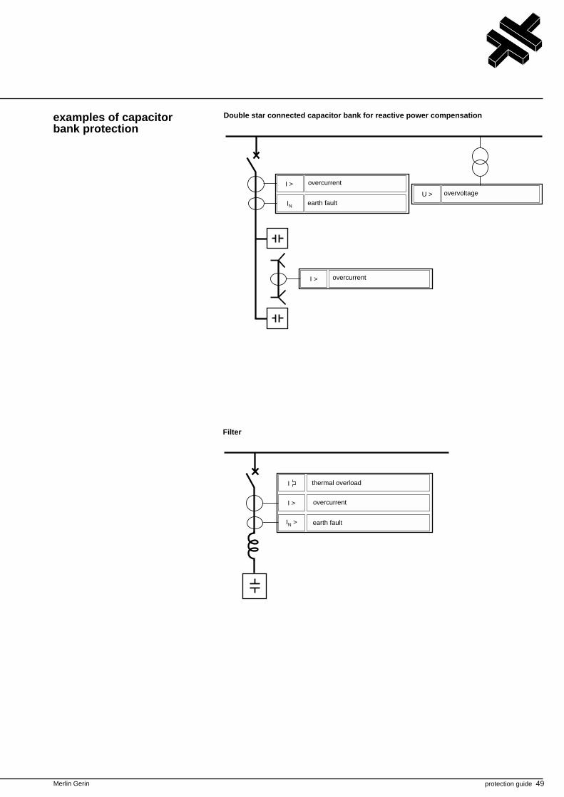
examples of capacitorbank protection
Double star connected capacitor bank for reactive power compensation
Filter
IN
I >
U >
I >
I >
IN >
I
earth fault
overcurrent
overvoltage
overcurrent
earth fault
overcurrent
thermal overload
50 protection guide Merlin Gerin
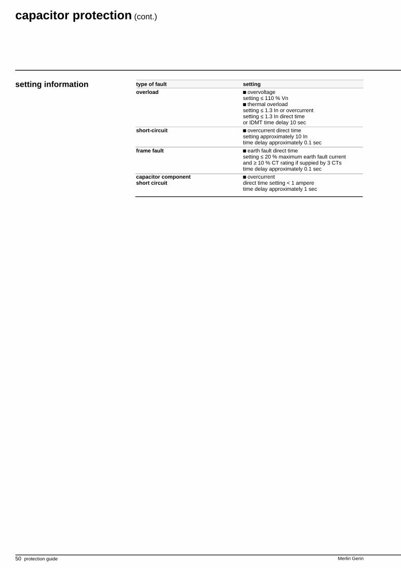
setting information
capacitor protection (cont.)
type of fault settingoverload overvoltage
setting ≤ 110 % Vnthermal overload
setting ≤ 1.3 In or overcurrentsetting ≤ 1.3 In direct timeor IDMT time delay 10 sec
short-circuit overcurrent direct timesetting approximately 10 Intime delay approximately 0.1 sec
frame fault earth fault direct timesetting ≤ 20 % maximum earth fault currentand ≥ 10 % CT rating if suppied by 3 CTstime delay approximately 0.1 sec
capacitor component overcurrentshort circuit direct time setting < 1 ampere
time delay approximately 1 sec

Merlin Gerin protection guide 51
52 protection guide Merlin Gerin
Merlin Gerin protection guide 53
introduction Protection or measuring devices requiredata on the electrical rating of the equipmentto be protected.
For technical, economic and safety reasons,this data cannot be obtained directly fromthe high voltage equipment power supply;the following intermediary devices areneeded:
voltage transformers (VT),current transformer (CT),core balance CTs to measure earth fault
current.
sensors
These devices fulfill the following functions:reduction of the value to be measured
(e.g.1500/5 A),galvanic isolation,providing the power required for data
processing and for protection operationitself.
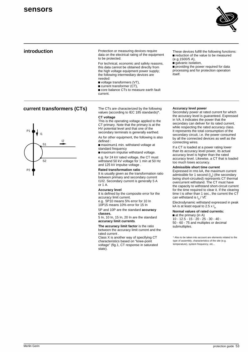
current transformers (CTs)
P1
P2
S1
S2
I2
I1
The CTs are characterized by the followingvalues (according to IEC 185 standards)*.
CT voltageThis is the operating voltage applied to theCT primary. Note that the primary is at theHV potential level and that one of thesecondary terminals is generally earthed.
As for other equipment, the following is alsodefined :
maximum1 min. withstand voltage atstandard frequency
maximum impulse withstand voltage.
e.g. for 24 kV rated voltage, the CT mustwithstand 50 kV voltage for 1 min at 50 Hzand 125 kV impulse voltage .
Rated transformation ratioIt is usually given as the transformation ratiobetween primary and secondary currentI1/I2. Secondary current is generally 5 Aor 1 A.
Accuracy levelIt is defined by the composite error for theaccuracy limit current.e.g. 5P10 means 5% error for 10 In10P15 means 10% error for 15 In
5P and 10P are the standard accuracyclasses.5 In, 10 In, 15 In, 20 In are the standardaccuracy limit currents.
The accuracy limit factor is the ratiobetween the accuracy limit current and therated current .Class X is another way of specifying CTcharacteristics based on "knee-pointvoltage" (fig.1, CT response in saturatedstate).
Accuracy level powerSecondary power at rated current for whichthe accuracy level is guaranteed. Expressedin VA, it indicates the power that thesecondary can deliver for its rated current,while respecting the rated accuracy class.It represents the total consumption of thesecondary circuit, i.e. the power consumedby all the connected devices as well as theconnecting wires.
If a CT is loaded at a power rating lowerthan its accuracy level power, its actualaccuracy level is higher than the ratedaccuracy level. Likewise, a CT that is loadedtoo much loses accuracy.
Admissible short time currentExpressed in rms kA, the maximum currentadmissible for 1 second (I
th) (the secondary
being short-circuited) represents CT thermalovercurrent withstand. The CT must havethe capacity to withstand short-circuit currentfor the time required to clear it. If the clearingtime t is other than 1 sec., the current the CTcan withstand is I
th / Vt.
Electrodynamic withstand expressed in peakkA is at least equal to 2.5 x I
th
Normal values of rated currents:at the primary (in A)
10 - 12.5 - 15 - 20 - 25 - 30 - 40 -50 - 60 - 75 and multiples or decimalsubmultiples.
* Also to be taken into account are elements related to thetype of assembly, characteristics of the site (e.g.temperature), system frequency, etc...
54 protection guide Merlin Gerin
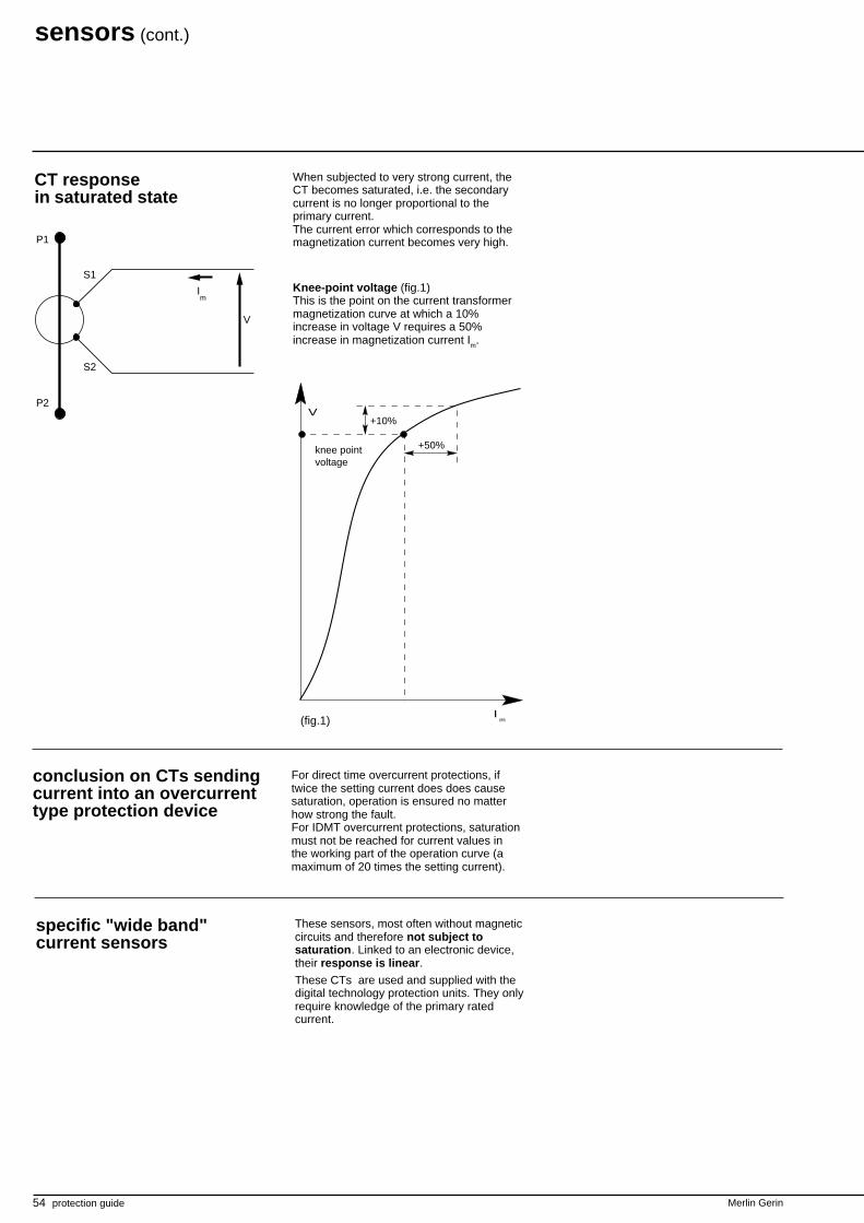
CT responsein saturated state
+10%
+50%
Im
V
(fig.1)
P1
P2
S1
V
S2
Im
When subjected to very strong current, theCT becomes saturated, i.e. the secondarycurrent is no longer proportional to theprimary current.The current error which corresponds to themagnetization current becomes very high.
Knee-point voltage (fig.1)This is the point on the current transformermagnetization curve at which a 10%increase in voltage V requires a 50%increase in magnetization current Im.
conclusion on CTs sendingcurrent into an overcurrenttype protection device
For direct time overcurrent protections, iftwice the setting current does does causesaturation, operation is ensured no matterhow strong the fault.For IDMT overcurrent protections, saturationmust not be reached for current values inthe working part of the operation curve (amaximum of 20 times the setting current).
knee pointvoltage
specific "wide band"current sensors
These sensors, most often without magneticcircuits and therefore not subject tosaturation. Linked to an electronic device,their response is linear.These CTs are used and supplied with thedigital technology protection units. They onlyrequire knowledge of the primary ratedcurrent.
sensors (cont.)
Merlin Gerin protection guide 55
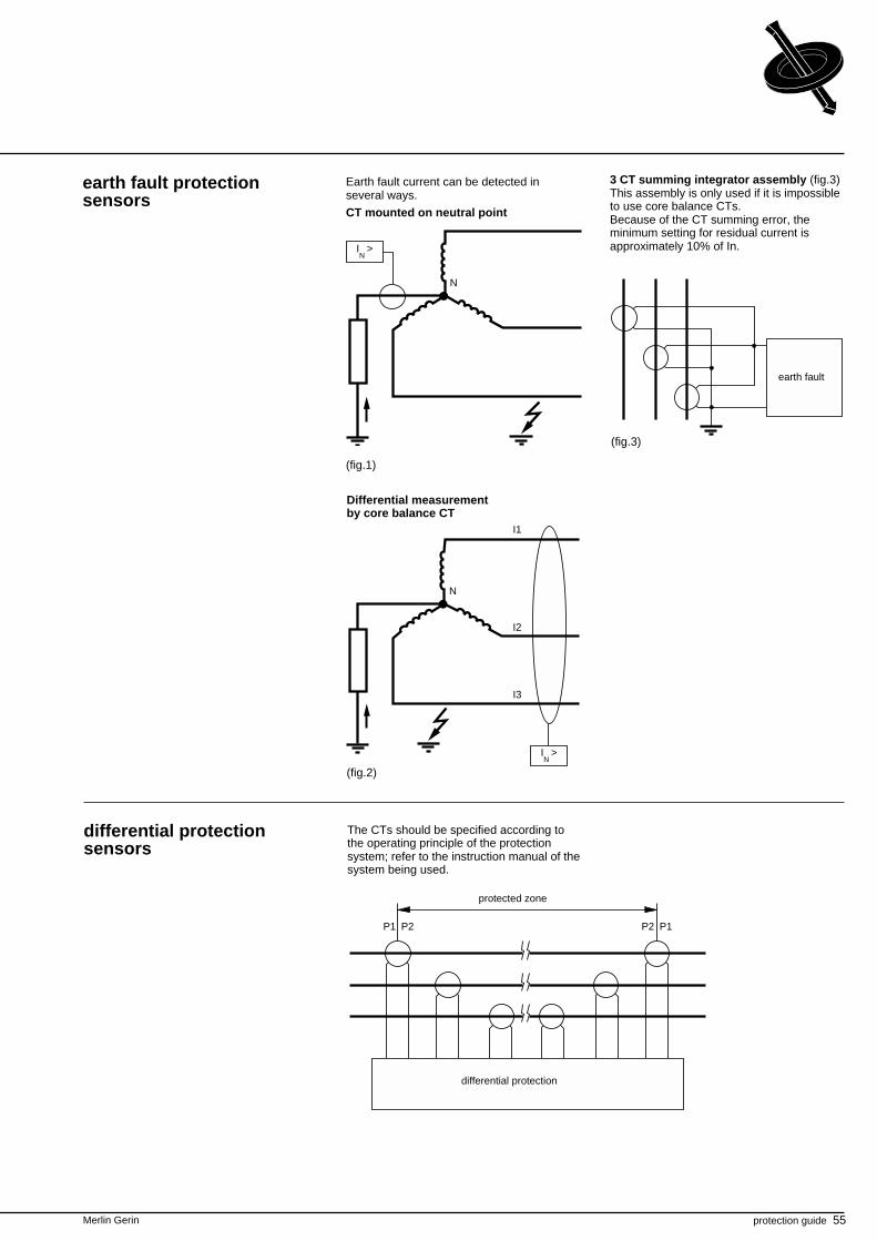
earth fault protectionsensors
Earth fault current can be detected inseveral ways.
CT mounted on neutral point
3 CT summing integrator assembly (fig.3)This assembly is only used if it is impossibleto use core balance CTs.Because of the CT summing error, theminimum setting for residual current isapproximately 10% of In.
(fig.1)
(fig.2)
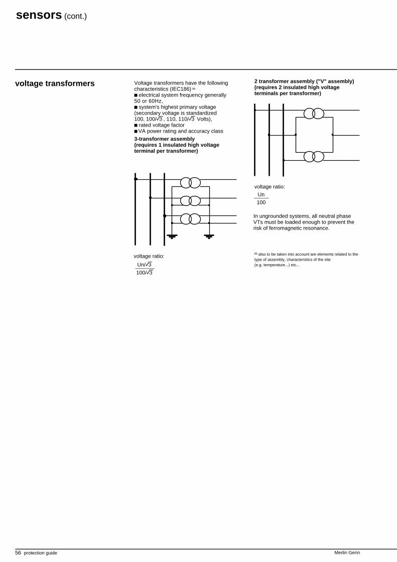
differential protectionsensors
The CTs should be specified according tothe operating principle of the protectionsystem; refer to the instruction manual of thesystem being used.
P1 P2 P2 P1
differential protection
protected zone
Differential measurementby core balance CT
N
IN
>
(fig.3)
earth fault
N
I1
I2
I3
IN
>
56 protection guide Merlin Gerin
Voltage transformers have the followingcharacteristics (IEC186) (1)
electrical system frequency generally50 or 60Hz,
system's highest primary voltage(secondary voltage is standardized100, 100/ , 110, 110/ Volts),
rated voltage factor VA power rating and accuracy class
3-transformer assembly(requires 1 insulated high voltageterminal per transformer)
voltage transformers 2 transformer assembly ("V" assembly)(requires 2 insulated high voltageterminals per transformer)
voltage ratio:
In ungrounded systems, all neutral phaseVTs must be loaded enough to prevent therisk of ferromagnetic resonance.
(1) also to be taken into account are elements related to thetype of assembly, characteristics of the site(e.g. temperature...) etc...
Un
100
Un/
100/
voltage ratio:
sensors (cont.)
Merlin Gerin protection guide 57
notes

58 protection guide Merlin Gerin
notes

Schneider Electric SA postal addressCentre Merlin GerinF - 38050 Grenoble cedex 9tel: (33) 76 57 60 60telex: merge 320 842 F
CG0021/1E
As standard specifications and designs change from timeto time, please ask for confirmation of the information givenin this publication.
Publication: Schneider Electric SA - 01/1996Layout: IdraImpression:
this document has been printed on ecological paper.