Embed Size (px)
Citation preview
International Conference on Renewable Energies and Power Quality (ICREPQ’18) Salamanca (Spain), 21th to 23th March, 2018
Renewable Energy and Power Quality Journal (RE&PQJ) ISSN 2172-038 X, No.16 April 2018
Protection Systems for Multi-Terminal HVDC Grids
D.M. Larruskain1, V. Valverde1, E. Torres1, G. Buigues1, M. Santos2
1 Department of Electrical Engineering E.I. Bilbao., University of the Basque Country UPV/EHU
Alda. Urquijo s/n, 48013 Bilbao (Spain) Phone/Fax number:+0034 946 014970, e-mail: [email protected]
2 Tecnalia
Phone, 946 430 069, fax: 901 760 009, e-mail: [email protected]
Abstract. Nowadays the protection of Voltage Sourced Converters (VSC-HVDC) is still a challenge as the high fault currents can damage seriously the converters. Nevertheless, the protection of HVDC grids is more complicated than point-to-point links, because of the specific requirements of HVDC grids. The protection system must detect and clear the faults within a demanding time. Moreover, HVDC circuit breakers are still not available, complicating the selective protection of the grid. Accordingly, since the protection of HVDC grids is so demanding, this issue is one of the biggest obstacles to develop HVDC grids. In this paper the protection system for HVDC grids is presented, including the measurement technology, fault detection and location algorithms and HVDC circuit breaker technology.
Key words Protection System, HVDC Grid, Fault Detecting Algorithm. 1. Introduction Multi-terminal DC grids (MTDC) aim to provide increased reliability to the interconnected grid. However, protection systems in these types of grids are more challenging than in point-to-point HVDC links [1]. Generally, MTDC systems are characterized by low series impedances, which lead to very high current gradients during short circuit faults. This implies strict timing requirements for the detection of DC faults and fast triggering of clearing actions in order to avoid important overcurrent damages to cables, converters and other DC system components [2] (the protection system must disconnect the faulted line in less than 10 ms in order to prevent damage to the power converters [1]). In this regard, the techniques proposed for fault location in point-to-point Line Commutated Converter (LCC-HVDC) systems or AC grids are thought to be inapplicable, mainly because of the excessive operation time [3], or due to key components being incompatible [4]. Besides, due to the different paths for the fault waves in MTDC grids, the fault location process gets
even more complicated compared to the case of two-terminal HVDC lines [1]. In order to develop an algorithm for protection against electrical faults it is necessary to collect voltage and current measurements at the different connection nodes of the system. The accuracy and speed of these measurements is essential for the proper functioning of the protection algorithms and is directly related to the safety and stability of the system. In addition, HVDC circuit breakers are considered essential for the development of multi-terminal HVDC grids, as they will make possible the application of selective protection systems, disconnecting only the part of the DC system affected by the failure. However, DC current interruption poses some issues that need still to be solved. In contrast to AC current, DC current has no natural zero current crossings so a DC breaker must force current to zero to interrupt the current. It is also necessary to provide a means to dissipate the large amount of energy stored in the system inductances and to suppress overvoltage after current interruption [5]. In this paper, the protection systems of MTDC grids are analyzed. A reliable protection system relies on the accurate measurement of voltage and current. These magnitudes must be processed with precise, fast and selective fault detection and location algorithms. The paper will also cover the circuit breaker technology, which is critical for the secure performance of the protection system. Finally, an example of a protection system will be applied to a MTDC. 2. HVDC measurement technology A. DC High Voltage Measurement There are two principal ways of measuring DC high voltage [6]:
https://doi.org/10.24084/repqj16.296 310 RE&PQJ, Vol.1, No.16, April 2018
- The use of resistive/resistive-capacitive (RC) dividers to convert high voltage to low voltage which could be easily measured
- The use of optical sensing principle to measure DC voltage
The DC voltage transformers based on RC voltage dividers are widely used in DC transmissions lines but they present some drawbacks that could affect measurement accuracy: resistance changes with high temperature, corona discharge, leakage current associated to insulation impedance or electromagnetic interferences [6-11]. Optical Voltage Transformers are a suitable alternative for DC high voltage sensing due to their light weight, small size, wide bandwidth, high accuracy, simple insulation structure, and electromagnetic interference immunity [12]. Their operating principle is based on the electro-optic effect (mainly on Pockels Effect) and their main drawback lies in loss of accuracy and stability under temperature changes and field perturbations [13-15]. B. High DC Current Measurement There are two principal techniques of measuring high DC current: - Hall effect based DC current transformers - Fiber-Optic Current Sensors (FOCS) Conventional high DC current transformers use the Hall effect to measure the magnetic field around the current to be measured. These types of transformers are accurate and reliable. However they present some drawbacks related to their complexity and the possibility to provide erroneous outputs due to asymmetric field distributions and disturbances from neighbor currents [16-17]. Fiber-optic current sensors, based on Faraday effect, offer significant advantages compared to Hall effect conventional transformers such as high fidelity (i.e., large bandwidth and no magnetic saturation), exceptional accuracy, higher safety of operation and environmental benefits (elimination of oil or SF6 insulation, no open secondaries and no ferro-resonance situations), reduced size and weight, dielectric design, adjustable turns-ratio, potentially low cost, ability to measure very high currents easily or integrated functions (e.g., voltage and current sensing in one device or integration into circuit breakers) [17-20]. These types of current transformers have reached in the last years a high degree of development and their use is being proposed for current measurement in DC grid primary protection systems [21].
3. HVDC fault detection and location algorithms
A. Unit vs. Non-Unit protection Similar to what happens in AC grid, these protection algorithms can be divided into non-unit and unit protection methods [3]: − Non-unit protection (commonly referred to as single-
ended protection) are based only on locally measured voltage and/or current for detection of internal faults, so they do not require a communication channel. The main advantage is that detection may occur very fast since no communication delay is introduced. However, to obtain full selectivity, an electrical discontinuity has to be introduced in the main circuit (e.g. a DC reactor) [22].
− Unit protection (commonly referred to as double-ended protection) rely on information obtained at both ends (local and remote) in the decision. This implies a transmission delay due to the communication channel, thereby limiting the detection time. However, double-ended approaches do not usually require additional main circuit equipment to limit the forward reach since this can be sensed at the remote side [22].
However, the time scale needed for the operation of HVDC grid protection is around 10 to 100 times shorter than for AC grid protection. This is why non-unit protection methods are seen as the preferred solution. A first common step in the definition of communication-less protection schemes is the identification of one or more variables that are available or derivable from local terminal measurements (DC voltage and current, their derivatives or their associated coefficients from wavelet transformations) and can act as a 'fault marker' when exceeding a predefined threshold. If the predefined threshold is exceeded, the fault is considered to be detected and a clearance sequence must be initiated. The adequate selection of these threshold values, along with sufficient margins, will ensure selectivity (it should be avoided that any transient that is not associated with a fault is finally cleared by the relay) [2]. Therefore, the non-unit protection is usually a preferred option for MTDC grids, but with some limitations since it cannot guarantee absolute selectivity. Therefore, in the context of future MTDC grids, the non-unit protection may be used as the main protection and unit protection may serve as a backup [23]. B. Differential Current protection vs. Travelling Wave
protection Many protection methods have been proposed so far by different authors, but basically, all DC fault detection and location methods can be classified in two main groups [24]:
https://doi.org/10.24084/repqj16.296 311 RE&PQJ, Vol.1, No.16, April 2018
− Direct measurement based methods, such as overcurrent protection method, differential current method, distance protection, etc.
− Signal processing based methods, such as travelling wave methods, neural network methods, etc.
Differential current protection, which has also been used in three-phase AC systems for a long time, is frequently presented as a valid fault detection approach in meshed HVDC grids [25]. Differential current protection relies on measuring the currents at both line ends, comparing the difference between the two measure currents with a predefined threshold: if the threshold is exceeded, the protection is tripped. To this purpose, a fast telecommunication infrastructure is needed in order to send the current measurement from one end to other [24]. The applicability of this approach is somehow problematic in HVDC systems with long transmission lines. The signal propagation time on a 200 km long fibre optic cable is around 1 ms and, since the rise of the fault currents is in the range of a few kA/ms, a delay of 1 ms per 200 km cannot be considered negligible [25]. Considering that HVDC transmission line length is usually several hundred kilometres, this communication delay could affect the fault clearance time [26]. Besides, the reliability of the differential current protection system would depend on telecommunication system’s availability, whose installation increases the costs [25]. There are also several other problems to consider when using current differential protection in HVDC systems such as distributed capacitance current problem, lack of valid setting principle, etc. [27]. Therefore, in many cases, telecommunication-based DC protection systems are not acceptable due to economic and reliability reasons. In these cases, a local protection principle should be preferred [25], where conventional current differential schemes were used as a backup protection [28]. At present, the most commonly used fault-detection and location techniques for HVDC systems are mainly based on travelling wave methods [29-31]. In this regard, using travelling wave based technologies is more advantageous for the HVDC line than for the AC line, considering that the DC line has a simpler structure and converters mainly reflect waves instead of refracting them [32]. Travelling wave methods are based on the fact that any disturbance on a transmission line produces travelling waves along its length, where these travelling waves appear as a result of charging and discharging the line capacitance and line inductance of the transmission line. Each wave is composed of different frequencies, from a few kilohertz to several megahertz, and has a propagation speed near the speed of the light. Since travelling wave based methods require measurements of the arrival time at the terminals of fault generated surges, in order to determine the distance to the fault, a signal processing tool is necessary to get this arrival time [24]. Travelling-wave-based methods have usually fast response and high accuracy. Their performance is not easily affected by different factors, such as bus configuration,
fault types, ground resistance, loading conditions, and system parameters [29-31]. However, one of the main issues with travelling wave based methods is related to their practical application, since they depend heavily on the high sampling rate, and are therefore difficult to implement, even in hardware. Moreover, these methods can be easily influenced by noise, interferences and signal disturbances [28, 32], and more importantly, they may lose reliability when it comes to high impedance fault situations. At present, identification of the travelling wave head and its arriving time is mainly achieved by computing the slope of measured voltages and currents, so its accuracy is affected by fault location and transition resistance [33]. Besides, one important challenge in travelling wave-based fault location system resides in faulty section identification for combined overhead line and underground cable. This challenge is due to the reflections of the fault signal from the joint-point and the fault point, as well as the unequal travelling wave velocities in line and cable [30]. Similar to other approaches, in general, travelling-wave based methods for fault location are grouped into two subcategories with respect to the measurements they employ at the receiving and/or sending end of the transmission line [30]: − The single-ended principle uses the fault induced
transient travelling waves and the associated reflected waves at one line terminal in order to determine the fault location.
− The double ended (synchronized) travelling wave principle calculates the fault distance making use of the time difference between the absolute arrival time of fault induced initial surges measured at both terminals of the line.
The double ended principle is regarded as more reliable than the single ended one, since it only uses the fault generated initial surges. However, it requires equipments to be installed at both ends of the supervised line, where its accuracy may be affected by the errors of the line length and the synchronization clock system, such as the global positioning system (GPS). The single ended approach is more cost effective, but its reliability may not be satisfactory due to the complexity of the fault reflected surge [35]. 4. HVDC breaker technology Different interrupting methods have been proposed, which differ in how current zero condition is achieved [36]:
• Inverse voltage generating method. The current is forced to zero by means of increasing the arc voltage to a value higher than the system voltage.
• Current commutating method. Parallel paths are provided in the circuit breaker to commutate the current, so the energy stored in the circuit can be dissipated or a high-frequency oscillating current is obtained.
https://doi.org/10.24084/repqj16.296 312 RE&PQJ, Vol.1, No.16, April 2018
• Inverse current injecting method. A high frequency inverse current is injected that interferes with the current to interrupt.
Using the previous techniques, different topologies of DC circuit breakers have been proposed which can be classified in three different groups: mechanical, solid state and hybrid circuit breakers [37-39]. A. Mechanical breaker They consist of a conventional (mechanical) AC breaker with a parallel circuit to create a current zero crossing. In passive HVDC circuit breakers, the parallel circuit becomes unstable under some conditions so an oscillation with increasing amplitude is produced until current zeros are created where the arc can be extinguished. In contrast, in active HVDC breakers an artificial zero current is produced by actively switching a commutation path including a pre-charged capacitor in combination with an inductance. The value of the operation speed of mechanical breakers is in the order of tens of ms. B. Solid state breaker
They consist of several solid state switches, usually IGBTs, which have the ability to turn off the current even though it does not have zero crossings. A number of semiconductor switches are connected in parallel and in series, in order to achieve the required breaking current capability. As they are mostly unidirectional devices, a minimum of two devices would be necessary to achieve a bidirectional circuit breaker, which increases the switch count and so, the device cost. In contrast, semiconductor switches are extremely fast, so the operation speed of solid state circuit breakers is very high, being in the order of a few ms. C. Hybrid breaker
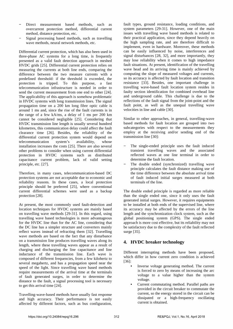
Mechanical DC breakers are relatively cheap but their operation speed and current breaking capacity is lower, which limits their application in DC grids based on Voltage Source Converters (VSC) with very limited overcurrent withstand. In contrast, solid state breakers are much faster but semiconductor switches has a permanent on resistance which causes solid state circuit breakers to have larger losses than mechanical DC breakers. In this context, hybrid breakers based on the combination of mechanical and power electronic switches have been proposed to take advantage of both technologies, i.e. fast current interruption with low steady-state losses. Industrial prototypes have been developed by manufacturers, being described in [40, 41]. 5. Study case In this section, an example of the application of a non-unit protection system is included. For the study case, the HVDC grid test system developed in [42] has been used. The test system is composed of two offshore wind farms and two onshore networks connected by five cables, as
shown in Fig. 1. The converters are half-bridge MMC with symmetric monopolar configuration. The DC voltage is ± 320 kV, and the AC voltage 400 kV. There are five cables: links 13 and 14 (200 km), link 24 (150 km), links 12 and 34 (100 km).
Fig. 1. Four terminal HVDC grid test system [42].
Converter 1 and 2 control the active power, converter 3 and 4 control the direct voltage. Droop control is implemented to increase the reliability of the HVDC grid. A. Protection system The protection system presented in this paper is a non-unit protection based on local measurements. The protection algorithm detects the DC faults in the first place. Faults are detected with undervoltage criteria. That way, a minimum voltage operation is set, 85% of the nominal voltage. Faults are discriminated when there are undervoltages for 100 µs after fault detection. The sampling frequency is 20 kHz. There is also an overcurrent protection that blocks the IGBTs when the current is greater than 1.5 times the rated value. Afterwards, faults are located by fault discrimination in order to assure a selective protection. Thus, two zones are determined, namely, internal and external zones. These zones are discriminated setting a 100 mH inductor between all the converters and the DC buses. Voltage derivative criterion is complemented with current derivative criterion to determine if it is a forward or backward fault. Therefore, faults are located in function of a minimum voltage derivative criterion and on the sign of the current derivative. B. HVDC line fault example
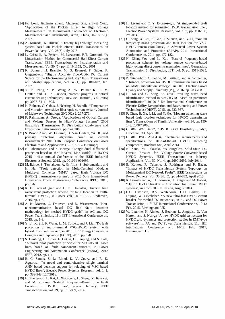
A pole-to-pole fault is applied in line 13, 25 km from converter 1, at time 1.0 s. The fault resistance is 0.01 Ω. After fault inception, the detection algorithm in each end of the affected line detects the fault, and the circuit breakers located at the line ends are opened. The delay of the circuit breaker is 2 [41]. Afterwards, the fault current in each pole of the line extinguish, and thus, there is a redistribution of currents in other lines. There are transient voltages in the lines, nevertheless, voltage is recovered without losing any converter, so the system maintains stability after the fault. Fig. 2 shows the pole-to-pole voltage and Fig. 3 the positive pole current for the five DC lines.
https://doi.org/10.24084/repqj16.296 313 RE&PQJ, Vol.1, No.16, April 2018
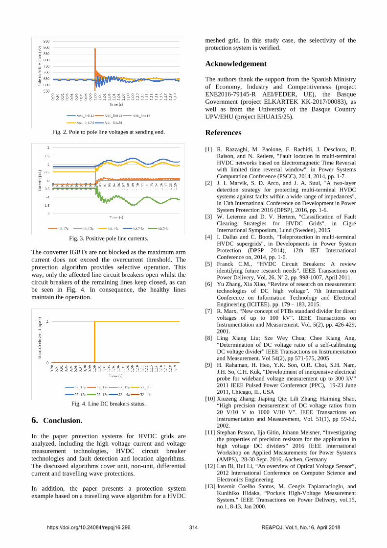
Fig. 2. Pole to pole line voltages at sending end.
Fig. 3. Positive pole line currents.
The converter IGBTs are not blocked as the maximum arm current does not exceed the overcurrent threshold. The protection algorithm provides selective operation. This way, only the affected line circuit breakers open whilst the circuit breakers of the remaining lines keep closed, as can be seen in Fig. 4. In consequence, the healthy lines maintain the operation.
Fig. 4. Line DC breakers status.
6. Conclusion. In the paper protection systems for HVDC grids are analyzed, including the high voltage current and voltage measurement technologies, HVDC circuit breaker technologies and fault detection and location algorithms. The discussed algorithms cover unit, non-unit, differential current and travelling wave protections. In addition, the paper presents a protection system example based on a travelling wave algorithm for a HVDC
meshed grid. In this study case, the selectivity of the protection system is verified. Acknowledgement The authors thank the support from the Spanish Ministry of Economy, Industry and Competitiveness (project ENE2016-79145-R AEI/FEDER, UE), the Basque Government (project ELKARTEK KK-2017/00083), as well as from the University of the Basque Country UPV/EHU (project EHUA15/25). References [1] R. Razzaghi, M. Paolone, F. Rachidi, J. Descloux, B.
Raison, and N. Retiere, "Fault location in multi-terminal HVDC networks based on Electromagnetic Time Reversal with limited time reversal window", in Power Systems Computation Conference (PSCC), 2014, 2014, pp. 1-7.
[2] J. I. Marvik, S. D. Arco, and J. A. Suul, "A two-layer detection strategy for protecting multi-terminal HVDC systems against faults within a wide range of impedances", in 13th International Conference on Development in Power System Protection 2016 (DPSP), 2016, pp. 1-6.
[3] W. Leterme and D. V. Hertem, "Classification of Fault Clearing Strategies for HVDC Grids", in Cigré International Symposium, Lund (Sweden), 2015.
[4] I. Dallas and C. Booth, "Teleprotection in multi-terminal HVDC supergrids", in Developments in Power System Protection (DPSP 2014), 12th IET International Conference on, 2014, pp. 1-6.
[5] Franck C.M., “HVDC Circuit Breakers: A review identifying future research needs”, IEEE Transactions on Power Delivery, Vol. 26, Nº 2, pp. 998-1007, April 2011.
[6] Yu Zhang, Xia Xiao, “Review of research on measurement technologies of DC high voltage”. 7th International Conference on Information Technology and Electrical Engineering (ICITEE). pp. 179 – 183, 2015.
[7] R. Marx, “New concept of PTBs standard divider for direct voltages of up to 100 kV”. IEEE Transactions on Instrumentation and Measurement. Vol. 5(2), pp. 426-429, 2001.
[8] Ling Xiang Liu; Sze Wey Chua; Chee Kiang Ang, “Determination of DC voltage ratio of a self-calibrating DC voltage divider” IEEE Transactions on Instrumentation and Measurement. Vol 54(2), pp 571-575, 2005
[9] H. Rahaman, H. Heo, Y.K. Son, O.R. Choi, S.H. Nam, J.H. So, C.H. Kuk, “Development of inexpensive electrical probe for wideband voltage measurement up to 300 kV” 2011 IEEE Pulsed Power Conference (PPC), 19-23 June 2011, Chicago, IL, USA
[10] Xiuzeng Zhang; Jiaping Qie; Lili Zhang; Haiming Shao, “High precision measurement of DC voltage ratios from 20 V/10 V to 1000 V/10 V”. IEEE Transactions on Instrumentation and Measurement, Vol. 51(1), pp 59-62, 2002.
[11] Stephan Passon, Ilja Gitin, Johann Meisner, “Investigating the properties of precision resistors for the application in high voltage DC dividers” 2016 IEEE International Workshop on Applied Measurements for Power Systems (AMPS), 28-30 Sept. 2016, Aachen, Germany
[12] Lan Bi, Hui Li, “An overview of Optical Voltage Sensor”, 2012 International Conference on Computer Science and Electronics Engineering
[13] Josemir Coelho Santos, M. Cengiz Taplamacioglu, and Kunihiko Hidaka, “Pockels High-Voltage Measurement System.” IEEE Transactions on Power Delivery, vol.15, no.1, 8-13, Jan 2000.
https://doi.org/10.24084/repqj16.296 314 RE&PQJ, Vol.1, No.16, April 2018
[14] Fei Long, Jianhuan Zhang, Chunrong Xie, Zhiwei Yuan, “Application of the Pockels Effect to High Voltage Measurement” 8th International Conference on Electronic Measurement and Instruments, Xi'an, China, 16-18 Aug. 2007.
[15] A. Kumada, K. Hidaka, “Directly high-voltage measuring system based on Pockels effect” IEEE Transactions on Power Delivery, Vol. 28(3), July 2013.
[16] L. Cristaldi, A. Ferrero, M. Lazzaroni, R.T. Ottoboni, “A Linearization Method for Commercial Hall-Effect Current Transducers” IEEE Transactions on Instrumentation and Measurement, Vol 50 (5), pp. 1149-1153, Oct 2001
[17] K. Bohnert, H. Brandle, M. G. Brunzel, P. Gabus, P. Guggenbach, "Highly Accurate Fiber-Optic DC Current Sensor for the Electrowinning Industry" IEEE Transactions on Industry Applications, Vol. 43(1), pp. 180-187, Jan. 2007.
[18] Y. N. Ning, Z. P. Wang, A. W. Palmer, K. T. V. Grattan and D. A. Jackson, “Recent progress in optical current sensing techniques,” Rev. Sci. Instrum., Vol. 66(5) pp. 3097–3111, 1995.
[19] K. Bohnert, G. Gabus, J. Nehring, H. Brändle, “Temperature and vibration insensitive fiber-optic current sensor”. Journal of Lightwave Technology 20(2002) 2, 267-276.
[20] F. Rahmatian, A. Ortega, “Applications of Optical Current and Voltage Sensors in High-Voltage Systems” 2006 IEEE/PES Transmission & Distribution Conference and Exposition: Latin America, pp. 1-4, 2006
[21] S. Pirooz Azad, W. Leterme, D. Van Hertem, “A DC grid primary protection algorithm based on current measurement” 2015 17th European Conference on Power Electronics and Applications (EPE'15 ECCE-Europe)
[22] N. Johannesson and S. Norrga, "Longitudinal differential protection based on the Universal Line Model", in IECON 2015 - 41st Annual Conference of the IEEE Industrial Electronics Society, 2015, pp. 001091-001096.
[23] M. Ikhide, S. Tennakoon, A. Griffiths, S. Subramanian, and H. Ha, "Fault detection in Multi-Terminal Modular Multilevel Converter (MMC) based High Voltage DC (HVDC) transmission system", in 2015 50th International Universities Power Engineering Conference (UPEC), 2015, pp. 1-6.
[24] R. E. Torres-Olguin and H. K. Hoidalen, "Inverse time overcurrent protection scheme for fault location in multi-terminal HVDC", in PowerTech, 2015 IEEE Eindhoven, 2015, pp. 1-6.
[25] A. K. Marten, C. Troitzsch, and D. Westermann, "Non-telecommunication based DC line fault detection methodology for meshed HVDC grids", in AC and DC Power Transmission, 11th IET International Conference on, 2015, pp. 1-8.
[26] Y. Li, X. Shi, F. Wang, L. M. Tolbert, and J. Liu, "Dc fault protection of multi-terminal VSC-HVDC system with hybrid dc circuit breaker", in 2016 IEEE Energy Conversion Congress and Exposition (ECCE), 2016, pp. 1-8.
[27] S. Guobing, C. Xinlei, L. Dekun, G. Shuping, and S. Jiale, "A novel pilot protection principle for VSC-HVDC cable lines based on fault component current", in Power Engineering and Automation Conference (PEAM), 2012 IEEE, 2012, pp. 1-4.
[28] R. C. Santos, S. Le Blond, D. V. Coury, and R. K. Aggarwal, "A novel and comprehensive single terminal ANN based decision support for relaying of VSC based HVDC links", Electric Power Systems Research, vol. 141, pp. 333-343, 12// 2016.
[29] H. Zheng-you, L. Kai, L. Xiao-peng, L. Sheng, Y. Jian-wei, and M. Rui-kun, "Natural Frequency-Based Line Fault Location in HVDC Lines", Power Delivery, IEEE Transactions on, vol. 29, pp. 851-859, 2014.
[30] H. Livani and C. Y. Evrenosoglu, "A single-ended fault location method for segmented HVDC transmission line", Electric Power Systems Research, vol. 107, pp. 190-198, 2// 2014.
[31] G. Song, X. Cai, S. Gao, J. Suonan, and G. Li, "Natural frequency based protection and fault location for VSC-HVDC transmission lines", in Advanced Power System Automation and Protection (APAP), 2011 International Conference on, 2011, pp. 177-182.
[32] H. Zheng-You and L. Kai, "Natural frequency-based protection scheme for voltage source converter-based high-voltage direct current transmission lines", Generation, Transmission & Distribution, IET, vol. 9, pp. 1519-1525, 2015.
[33] P. Tünnerhoff, C. Petino, M. Battiato, and A. Schnettler, "Distance protection for HVDC transmission lines based on MMC modulation strategy", in 2016 Electric Power Quality and Supply Reliability (PQ), 2016, pp. 283-288.
[34] H. Xu and G. Song, "A novel traveling wave head identification method in VSC-HVDC based on parameter identification", in 2015 5th International Conference on Electric Utility Deregulation and Restructuring and Power Technologies (DRPT), 2015, pp. 933-937.
[35] P. Chen, B. Xu, J. Li, and Y. Ge, "Modern travelling wave based fault location techniques for HVDC transmission lines", Transactions of Tianjin University, vol. 14, pp. 139-143, 2008// 2008.
[36] CIGRE WG B4.52, “HVDC Grid Feasibility Study”, Brochure 533, April 2013.
[37] CIGRE JWG A3/B4.34, “Technical requirements and specifications of state-of-the-art HVDC switching equipment”, Brochure 683, April 2014.
[38] K. Sano, M. Takasaki, “A Surgeless Solid-State DC Circuit Breaker for Voltage-Source-Converter-Based HVDC Systems”, IEEE Transactions on Industry Applications, Vol. 50, No. 4, pp. 2690-2699, July 2014.
[39] E. Kontos, R. Teixeira, S. Rodrigues and P. Bauer, “Impact of HVDC Transmission System Topology on Multiterminal DC Network Faults”, IEEE Transactions on Power Delivery, Vol. 30, No. 2, pp. 844-852, April 2015.
[40] R. Derakhshanfar, T.U. Jonsson, U. Steiger and M. Habert, “Hybrid HVDC breaker – A solution for future HVDC systems”, in Proc. CIGRE Session, August 2014.
[41] C.C. Davidson, R.S. Whitehouse, C.D. Barker, J.P. Dupraz, W. Grieshaber, “A new ultra-fast HVDC circuit breaker for meshed DC networks”, in AC and DC Power Transmission, 11th IET International Conference on, 10-12 Feb. 2015, Birmingham, UK
[42] W. Leterme, N. Ahmed, J. Beerten, L. Ängquist, D. Van Hertem and S. Norrga “A new HVDC grid test system for HVDC grid dynamics and protection studies in EMT-type software”, in AC and DC Power Transmission, 11th IET International Conference on, 10-12 Feb. 2015, Birmingham, UK.
https://doi.org/10.24084/repqj16.296 315 RE&PQJ, Vol.1, No.16, April 2018


![High Frequency Operation of a DC-AC-DC system for HVDC ... · Voltage Source Converters (VSCs) are generally considered to be the best option of for multi-terminal HVDC grids [2]](https://img.pdfslide.net/doc/110x75/5fd4c28a0a7fee74f019832d/high-frequency-operation-of-a-dc-ac-dc-system-for-hvdc-voltage-source-converters.jpg)