Embed Size (px)
Citation preview
Master’s Thesis inComputing ScienceExamensarbete DV32000-03-15ISSN 1100-1836
A General Protocol Stack Interface in Erlang
Peter Andersson Markus Kvisth
Computing Science DepartmentUppsala University
Box 311S-751 05 Uppsala
Sweden
This work has been carried out at:
Ericsson Software Technology ABErlang Systems
Torshamnsgatan 39 BBox 1214
SE-164 28 Kista
AbstractThis paper describes a general model for interfacing protocol stacks from applicationsdeveloped in the functional programming language Erlang. We discuss different problemareas, taking issues such as data- and control-flow, stack management and supervisioninto consideration and motivate proposed solutions with respect to the aspects ofusability, flexibility, robustness and efficiency. The final model is a result of theoreticalreasoning and knowledge gained from related research and development, from our ownprototyping and from discussions with experienced scientists working in associatedareas.
Part of the thesis work was, for the purpose of verification and further development, toimplement a prototype of the proposed theoretical model. The result of this work is alsodescribed in this paper.
The generality of the protocol stack interface model is achieved by dividing it into twoparts, one stack independent “upper” part and one stack dependent “lower” part. Thearchitecture of the upper part of a system based on this model is fully described in thisthesis. The lower part is to be designed and implemented at a later stage by following thedeveloped set of rules that constitute this part of the system. This activity should takeplace at the time the specifics of the protocol stack to be interfaced are actually known.
The major aim of this thesis work is to find a way to avoid “reinventing the wheel” everytime a new stack is to be interfaced from Erlang. We hope to accomplish this byproviding a thought-through model and a set of pre-made building blocks.
Supervisor: Gunilla HugossonExaminer: Erik Johansson
2
1. INTRODUCTION .................................................................................................................... 3
1.1 MOTIVATION ....................................................................................................................... 31.2 ERLANG............................................................................................................................... 7
2. CREATING A GENERAL PROTOCOL STACK INTERFACE SYSTEM IN ERLANG . 10
2.1 ARCHITECTURES OF A STACK INTERFACE SYSTEM IN ERLANG ............................................... 102.2 USABILITY AND THE USER INTERFACE.................................................................................. 122.3 MESSAGE DISPATCHING AND USER IDENTIFICATION.............................................................. 132.4 CONTROL AND SUPERVISION ............................................................................................... 202.5 STACK INTERFACE SYSTEM MANAGEMENT ........................................................................... 232.6 PROCESSES AND FUNCTION LIBRARIES ................................................................................. 232.7 CONNECTING THE INTERFACE SYSTEM TO A STACK............................................................... 242.8 RUNNING THE STACK INTERFACE SYSTEM IN A DISTRIBUTED ENVIRONMENT .......................... 252.9 PERFORMANCE................................................................................................................... 272.10 CONCLUSION ..................................................................................................................... 28
3. IMPLEMENTATION OF THE GENERAL STACK INTERFACE SYSTEM MODEL.... 30
3.1 IMPLEMENTATION OF THE STACK INTERFACE SYSTEM CHANNEL COMPONENTS....................... 303.2 IMPLEMENTATION OF THE CENTRAL INTERFACE SYSTEM COMPONENTS.................................. 343.3 IMPLEMENTATION OF USER APPLICATIONS ........................................................................... 383.4 THE STACK CONNECTION .................................................................................................... 403.5 CODE GENERATION ............................................................................................................ 503.6 METHODS FOR CRASH RECOVERY ........................................................................................ 513.7 FLAWS, RESTRICTIONS AND IMPROVEMENTS ........................................................................ 52
4. RELATED WORK................................................................................................................. 54
4.1 THE ERLANG TEST PORT FOR TTCN................................................................................... 544.2 GPRS................................................................................................................................ 564.3 CORBA ............................................................................................................................ 584.4 WINSOCK .......................................................................................................................... 59
ACKNOWLEDGEMENTS ........................................................................................................... 60
REFERENCES............................................................................................................................... 61
3
1. Introduction
1.1 MotivationAccessing protocol stacks is a common action in many applications, especially in the telecomindustry. Erlang is a well-suited programming language for implementing such applications. Anexample of a telecom system that interfaces various external protocol stack layers from its Erlangapplication is Ericsson GPRS [28], which is described in more detail in chapter 4. Other systems aree.g. the AXD-301 ATM Switch [21] and the Ericsson Access 910 Node [26]. Interfacing one or morelayers of a protocol stack can only be practically accomplished in a very limited number of ways,really. Hence, different software development projects waste precious time designing interface systemsin Erlang that end up looking very similar. You will find most protocol stacks today implemented inlanguages like C, C++ and/or in hardware (for performance). Interfacing is normally accomplished bycalling functions in a specific protocol service API, or by using a general Sockets [45] or Streams [44]interface. Such APIs provide abstraction on top of some fundamental streaming functionality (likepipes or file descriptors) for communication between an application and a device.
Developing an architecture for accessing protocol stack layers from a high-level language like Erlangis something that should be done thoroughly once and for all. A general interface model is needed thatis open for the different types of physical connections one may encounter and also takes issues such asefficiency and robustness into consideration. It is of course very important that the interface systemitself fits nicely into the Erlang environment and that the interface to the users is as straightforwardand intuitive as possible. The keyword here is usability.
There are many factors that affect usability. In article [13], for example, the author criticises theusability of the Windows Application Program Interface (Win32). Here are a few of his arguments:
• “The Windows API is accessed through a very large and complicated set of elements. Its size isdifficult to judge because what it exactly constitutes is far from clear”.
• “The huge number of elements comprising the API make it difficult to master and use effectively.As a result, the productivity of application architects, software developers and maintainers isnegatively affected".
• “Win32 provides 91 functions that create entities… All those functions receive parameters ofdifferent types in wildly differing order… The return value of the functions that create entities isalso inconsistent”.
The size of the user interface we propose cannot be compared to that of Win32, of course. But we feelitems such as these are relevant, however, and have indeed identified simplicity, intuitiveness andconsistency as important factors in our user interface discussion.
Our goal is to provide Erlang programmers with a common environment for interfacing protocolstacks. We have mainly focused on stacks that are controlled through an API, but our interface shouldwork well with other kinds of stacks as well, e.g. stacks that use message passing over file descriptorsdirectly instead. Again, generality is important, not only so that the interface model can comply withmost types of physical connections, but also so that only small changes, if any, are necessary in orderto adopt an implementation of the model to, for example, a new version of a protocol service API.Different stacks have different APIs. This means we cannot make any assumptions about functioncalls used for communicating with the stack or the data they contain. The only way to create acommon interfacing environment under these circumstances is by creating a set of rules for how thefunction calls (including possible callbacks) and their return values should be handled in Erlang.
Robert Ciampa writes that it is generally the top layers of the protocol stacks that are the mostinteresting for applications to interface: “Applications do not usually communicate with the lowerlayers; rather, they are written to interface with a specific communication library, like the popularWinSock library available in Windows-based workstations” [17]. More precisely, this would refer tothe Session Layer and above in the OSI model (see section 1.1.1). These are also the types of layers we
4
will focus on in our examples, but we do not exclude the possibility to interface lower layers as wellfrom the model we propose.
1.1.1 The conceptSince protocol stacks are a central part of our work we will give a short introduction to their basicprinciples and common terminology.
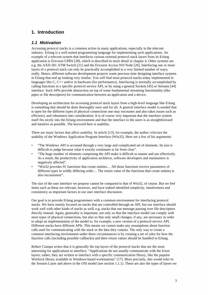
For obvious reasons there is no such thing as a physical “general purpose” protocol stack. However,ISO provides the OSI (Open System Interconnection) reference model [3] that we will try to oftenrelate theoretical discussions to for the sake of generality. TCP/IP [4], which has become a de factostandard for internet communication, is based on another reference model, called DARPA (explainedin [43]).
Figure 1: The OSI and DARPA models and their corresponding layers
The OSI ISO model was designed to establish data communications standards that would promotemulti-vendor interoperability. It consists of seven layers with a specific set of network functionsallocated to each layer and guidelines for implementation of the interfaces between the layers.Important principles of the OSI are that each layer should perform a well-defined function and thatlayer boundaries should be chosen to minimise the information flow across the interfaces.
Architectures for network communication systems are most often layered according to the OSI andDARPA models as this reduces design complexity. The purpose of each layer is to offer services to thelayer above, but to hide from it the details of how the services are actually implemented. In [16], aservice is defined in terms of service primitives. These are abstract representations of interactionsbetween a service user and the (N)-layer service provider. The provided service makes an abstractionof the particular interface and a primitive is an element of this service. We will refer to an applicationthat is connected to a protocol stack layer and is using its services as simply a user of that layer.Hence, a user may be an application using the services of the top Application Layer of the OSI modelor it may be an (N+1)-layer in general. In [16], the authors also define an (N)-entity as an activeelement communicating with the following other entities:
1. (N+1)-entities within the same system, through an (N)-interface.2. (N)-entities in other systems, using an (N)-protocol and the services provided by the (N-1)-layer.
These entities are called peer entities.3. (N-1)-entities within the same system, through an (N-1)-interface.
Furthermore, a protocol is defined as the rules and semantic and syntactic formats which specify thecommunication behaviour between entities. A layer gives its user the illusion that it communicates
Physical Layer
Data Link Layer
Network Layer
Transport Layer
Session Layer
Presentation Layer
Application Layer
Network InterfaceLayer
Application Layer
Host-to-HostTransport Layer
Internet Layer
DARPAModel
OSI Model
5
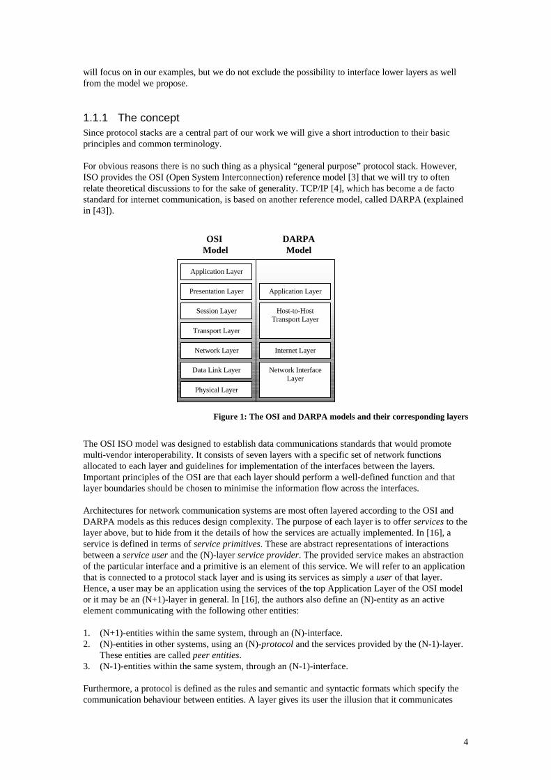
directly with its peer user in another stack (a virtual connection), although the communicationactually goes through all the underlying layers in the two stacks. The bottom layer (e.g. the PhysicalLayer in OSI) is what physically connects to protocol stacks together. Because of the layeredarchitecture it is possible to replace a layer with a new one without affecting its users (e.g. if thephysical link is a wire but is to be replaced with radio communication) as long as the service (theinterface) of the layer remains the same.
Figure 2: Stack principles, peer-to-peer communication
A layer can have several users if the layer protocol has support for it (i.e. if messages in that protocolcontain information about which user they are destined for). Formally, the layer in question thenneeds to have support for the existence of multiple entities where each may be connected, one-to-one,with a user entity. These entity-pairs form so-called SAPs (Service Access Points) [3] and each SAPmay support multiple connections, each identified by a CEP (Connection End Point) identifier [3].
As a general stack layer architecture would support 1..n entity per layer, so must a general interfacesystem. This implies that a dispatching functionality handling the mapping between SAPs, CEPs anduser entity identities is required. The possibility to interface more layers from one user entity adds yetanother dimension to the complexity of such an interface system (as will be discussed more thoroughlyin the next chapter). “Not all methods of network communication extend to all layers of the full OSIreference model. For example, internetworking communications between programs on differing hostsusing reliable TCP/IP communications might use all layers of the OSI reference model, while localWindows for Workgroups communications within the same network using the NetBEUI protocolmight have communications occurring only at the Data Link Layer and Physical Layer levels”, [46].This quote implies that for an interface system to be general, it needs to allow the users to interfacemultiple stack layers simultaneously.
1.1.2 Stack interfacesThe type of the provided stack interfaces, the methods of using them and the way they send messagesto their users, can be very different for different stacks and stack layers. This may depend on reasonssuch as special purposes of the stack, if it supports single or multiple users, the implementationlanguage, the degree of optimisation, the operating system being used, the level of the layer tointerface, etc. Due to reasons like those, a stack vendor might, instead of using an API (which seemsto be most common), for example create an interface that provides stack communication in the shapeof reading and writing bytes to and from file descriptors or one that uses an abstraction for messagepassing between processes. The vendor might choose to have a stack layer send messages to the usersin a “one socket per user” or an “all users on one socket” fashion. The latter would require themessages to be tagged with their destination user identity (as they are all sent on the same stream), orthat the users take turn to request the stack for new messages.
The general Streams [44] library and Sockets [45] (for IP communication) are commonly usedinterfacing mechanisms. These are primitive APIs for controlling and passing data over some type ofport. According to [44], Streams provides a uniform mechanism for implementing network services
2 UserLayer N
Layer 1
Layer 2
…
N User
2 UserLayer N
Layer 1
Layer 2
…
N User
Layer N protocol
Layer 2 protocol
Layer 1 protocol
Stack 1 Stack 2
6
and other character-based I/O. It is typically a full-duplex connection between a process and on opendevice (or pseudo-device). Examples of data passing functions are read(), write(), getmsg() andputmsg(). The function ioctl() is used for control. Streams uses a priority data field in its protocolmessages. This priority classifies messages and determines the order in which they should beprocessed if queued. A stack interface system based on Streams could choose to hide this parameterfrom the stack users (probably preferred unless performance is critical) or require them to includedthis as local primitive Quality of Service information (hence not necessarily revealing Streams as theunderlying interface mechanism). A Socket, normally identified simply by a small integer, is definedby the following data:
• The remote host identification number or address• The remote host port number• The local host identification number or address• The local host port number
The application programmer accesses the mechanism using a small number of functions like socket(),bind(), connect(), listen() and accept(). An application would use Sockets for implementing serviceson top of either UDP/IP or TCP/IP. A general interface system in Erlang could of course provide aprogramming environment on top of Sockets, like on any other mechanism. But since a user-friendlyinterface to Sockets already exists for Erlang programmers, it is maybe more likely that this APIwould be used instead of, or in parallel with, such an interface system. However, examples show thatprotocol stack vendors may chose to use TCP/IP for interfacing layers in other types of stacks (see e.g.MicroLegend SS7, [42]). In such cases, the interface system, to be used by e.g. an SS7 userapplication, must of course be implemented on top of Sockets.
The de facto standard for interfacing TCP/IP in the Windows environment is using WinSock [10] –“Sockets for Windows”. We will take a look at that interface system separately in chapter 4.
In [18], Claes Wikström discusses the benefits of using dynamic interfaces: “Using this capability it ispossible to implement a general purpose encoder/decoder which maps data objects from the languageto and from a stream of bytes which can be sent onto a network”. Dynamic interfacing simply meansthat marshalling data (i.e. message coding and decoding) can be performed dynamically at runtime.(This is closely related to dynamic typing). As stated previously, protocol stacks (at least the toplayers) are traditionally implemented in languages such as C or C++. Using an API for accessingthese services normally means having to statically link the user code to the service interface code.Such interfaces cannot be changed in runtime without being recompiled. With a dynamic interface,linking code is not necessary and the interface may be updated in runtime, which often is animportant requirement for telecom applications. Claes Wikström argues that dynamic interfacing doesnot impose any extra demands on either the interface client (in our case the user) or server (in ourcase the service provider). Rather it should simplify the design and implementation of both client andserver. This, together with the fact that Erlang uses a dynamic type system, means that encountering adynamic interface to a protocol stack layer would only make the interfacing a lot simpler thanencountering a traditional API (which we, of course, have to assume we most of the time will). As wewill see later, by applying the idea of dynamic interfacing to the interface between the user applicationand the stack interface system, we can still get many of the benefits discussed here, even if theunderlying stack layer interface may be of static nature.
1.1.3 ExamplesThroughout this report we will often refer to the Signalling System No.7 (SS7) standard protocol stack[7] and will particularly use layers of this stack for our examples. The SS7 stack is built on ITU-T andANSI standard protocols developed and used for signalling in telecom networks. The protocol stackconsists of four layers. The lowest three layers are combined into one set of protocols referred to as theMessage Transfer Part (MTP). The MTP layers correspond to the three lowest layers of the OSImodel. At level 4, two sets of protocols span the corresponding layers 4 to 7 of OSI: the ISDN UserPart (ISUP) and the Transaction Capabilities Application Part (TCAP) on top of the SignallingConnection Control Part, SCCP. ISUP is used for managing phone connection oriented
7
communications. TCAP/SCCP handles all other messaging, connectionless as well as connectionoriented.
In this paper we will adopt the SS7 notation request for a function-call or a message from a user entityto a stack layer entity, and indicator for function calls and messages going in the opposite direction(from a users point of view an indicator function is a function callback).
1.2 ErlangThe main concepts of Erlang itself have been of major importance during the design of our interfacemodel. We will therefore give a brief introduction to the language and to some of the tools that arerelated to our work. For a thorough introduction, the reader is referred to [8].
1.2.1 The languageErlang is a functional language with declarative syntax similar to that of ML and Prolog. It is aimedat implementing concurrent, distributed and fault-tolerant systems with soft real-time requirements.The language is intentionally kept small for reasons of simplicity of use as well as for robustness andefficiency.
A program is divided into one or several modules. A module consists of functions which, in turn,consists of clauses. In order to choose which clause to execute when a function is called Erlang usespattern matching. Pattern matching is a fundamental concept of the language and is also used formatching incoming messages, conditional expressions and for variable assignment.
Variables are dynamically typed and can only be assigned once1. A variable either contains a constantor a compound data object. A constant object can be an atom, an integer, a float or a process identifier,while a compound object is a list or a tuple of data objects. There are also a few more types of dataobjects, of which the one with greatest relevancy to our work is the 'binary’ type, used to store an areaof untyped memory.
Erlang programs are compiled to run on a virtual machine in the Erlang runtime system (ERTS).ERTS provides these programs with a consistent operating system interface on all platforms, memoryhandling, a concurrent processes environment, distribution and means of fault tolerance. The realstrength of Erlang comes from the inclusion of these concepts into the language.
1.2.2 ConcurrencyErlang programs execute as concurrent processes. Erlang processes are started by a single functioncall and are lightweight. Communication between processes is done by asynchronous messagepassing. All processes are equipped with a message box for incoming messages, and can suspendthemselves when waiting for messages to arrive.
1.2.3 DistributionA running ERTS is generally running as a process in an operating system and is also known as anErlang node. Communication between Erlang processes running on different nodes works in the sameway as when they are on the same node. That means that programs can easily be scaled up fromrunning on one node into running on several.
Distribution is often used to create reliable and fault tolerant systems, but also to divide heavycomputations among several processors. Additionally, it is possible to make a C program act and looklike an Erlang node. This is often referred to as a C node.
1.2.4 Fault toleranceRobust and fault tolerant systems have to be able to detect and survive failures. To do that, Erlangprovides the following mechanisms:
1 Non-destructive assignment.
8
• Monitoring of expression evaluation (catch/throw). Used for protection against errors insequential code.
• Monitoring of the behaviour of other processes. A process can link itself to another process inorder to be informed when and why that process terminates. This mechanism also works in thesame way when the processes reside on different nodes as when they reside on the same. Aprocess on a node can also monitor the status of another node.
1.2.5 AdditionalAn Erlang program has the possibility to interact with a program written in another language (i.e.running outside the Erlang Runtime System) through a port. A port is a byte oriented communicationchannel between Erlang and the external program. To the Erlang processes it looks just like anordinary Erlang process, whereas the external program uses the underlying mechanism, which is apair of file descriptors. The process that creates the port is appointed “port owner”. It is theadministrator of the port and will be the destination of all messages sent from the external programthrough the port. Using the same basic principle of operation as for ports, an Erlang process can opena socket. A socket is the Erlang interface towards Sockets in the operating system.
In order to be able to interpret the data sent from Erlang through the port there is a C function library2
that can convert this data into (or from) Erlang external format. In this format the data is built andmanipulated in same way as it is done inside Erlang.
Interaction with an external program over a port means that the operating system has to perform atask switch between the ERTS process and the other program before messages can arrive. Since taskswitches in the OS are time consuming this might cause large overhead, especially if the amount ofmessages passed through the port is large. If time is a critical issue a possible solution might be to uselinked in drivers instead. Linked in drivers are external programs that are executed by the ERTSprocess. The advantage of this is that the external programs do not run as separate processes and thusthat no task switching or message copying is required. The rather severe downside is that if theexternal program fails it will halt the entire Erlang system.
1.2.6 OTPThe Open Telecom Platform (OTP) is a system development platform for building and runningreliable, high-performance telecommunications solutions on standard computer platforms. OTP isbuilt upon Erlang and it supplies the basic functionality used for building telecommunicationapplications, such as a real-time database, integration of externally sourced components, distribution,and methods for building supervision trees in order to achieve fault tolerant systems, code loading inruntime, etc. This provides for a highly productive environment where developers can concentrate onthe special aspects of their own product without having to worry about the basic mechanisms. Exceptfor the language itself, tools and concepts included in the OTP that are of interest to us are the Orber,IC and behaviours.
The Orber is the Erlang implementation of an ORB (Object Request Broker), as specified in [1]. TheRequest Broker is the core of CORBA - a specification for interfacing and communicating withobjects in a distributed and possibly heterogeneous network. The broker functionality in CORBA hasmany similarities to central parts of our general stack interface model. Also, since layers of someprotocol stacks may be interfaced via the Erlang Orber, it is quite likely that a user application maywant to interface protocol stacks by means of CORBA in parallel to our proposed system. For thesereasons, and because IC and IDL are also quite interesting for us (see below), we have dedicated a partof our chapter on related work (4) to discuss CORBA further.
IC is an IDL (Interface Definition Language) to Erlang compiler. IDL is also specified in CORBA [1].Given different switches, IC can invoke different backends to generate client stub and server skeletoncode for various purposes. The typical use is of course to generate Erlang code to use with the Orber.However, IC may also compile IDL specifications into code that can be used for Erlang to C (and vice 2 Which naturally is only applicable in C programs.
9
versa) communication over a port. The actual port protocol is transparent for both the client andserver. Yet another possibility is to specify IDL interfaces that IC compiles into client and server codefor generic server behaviours (see below).
Associating a program with a so called behaviour is a way to declare that it will behave in a, by OTP,defined manner. It accomplishes this by implementing a pre-defined set of functions required for thatparticular behaviour. These callback functions will be invoked by the generic OTP implementation ofthe behaviour in question. The types of behaviours that OTP defines are, for example, those of servers,process supervisors, event-handlers and finite state machines. Apart from callback functions requiredfor their main purposes, programs using these behaviours must also have support for acting in asupervision tree (i.e. starting and stopping in a controlled manner) and for loading code in runtime.Behaviours are building blocks of robust systems.
10
2. Creating a general protocol stack interface system in ErlangIn this chapter we will discuss aspects of functionality and design involved in finding an appropriatesolution for interfacing protocol stacks. There are lots of issues and problems that we need to take intoconsideration, especially since we will attempt to create a model that is as general as possible (asmotivated in 1.1). The purpose of this chapter is to derive a suitable model seen from quite a fewdifferent perspectives. Many of the topics here can be related to similar issues that have been takeninto consideration in work such as the Erlang Test Port [31] and Ericsson GPRS [28]. See chapter 4for more information.
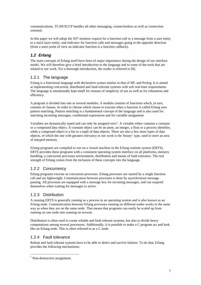
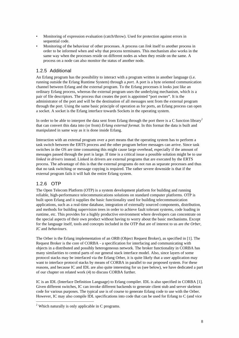
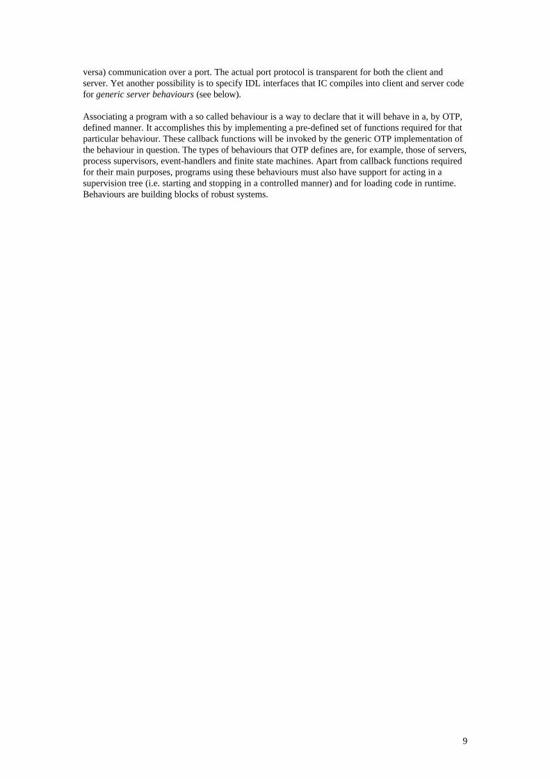
Let us begin by analysing a stack interface system in terms of the most fundamental functionality itshould have to provide. Think of it as a black box for now. Protocol stack users on an Erlang platformare connected at the front of the box and different layers of a protocol stack at the back (see Figure 3).Messages coming into the black box from the user side, requests, pass through the box and come outthrough the appropriate stack layer connections in the back. Messages coming into the stack,indicators, go from the layers into the corresponding black box connections and are then routed (ordispatched) to the rightful user addressees.
Figure 3: Connections
Figure 4: Request and Indicator
For the black box to be useful at all, not only must it be able to perform basic dispatching as describedabove, but also meet other important requirements. It must be flexible enough so that most protocolstack implementations can be connected to it without the need for changes in its fundamentalarchitecture (or in the implementation of the stack, of course). A high degree of efficiency, reliabilityand robustness are also necessary requirements, again for the sake of both usability and generality.Furthermore, it is an important preference that the interface is easy to use. Indeed, a lot of designissues will deal with making the right trade off between functionality requirements and preferences, aswe will see in the following sections.
2.1 Architectures of a stack interface system in ErlangAfter we have described what must be the most fundamental functionality and requirements on a stackinterface system, we may now proceed by mapping this functionality to basic system components. Thisway we attempt to get a first picture of what an interface system architecture could look like. First ofall, some basic components need to be identified that would handle the tasks involved in thecommunication between users and stack:
Protocol stackinterface
Protocolstack
Protocolstack users
Stack layers
user
addressee
request
users
indicator
11
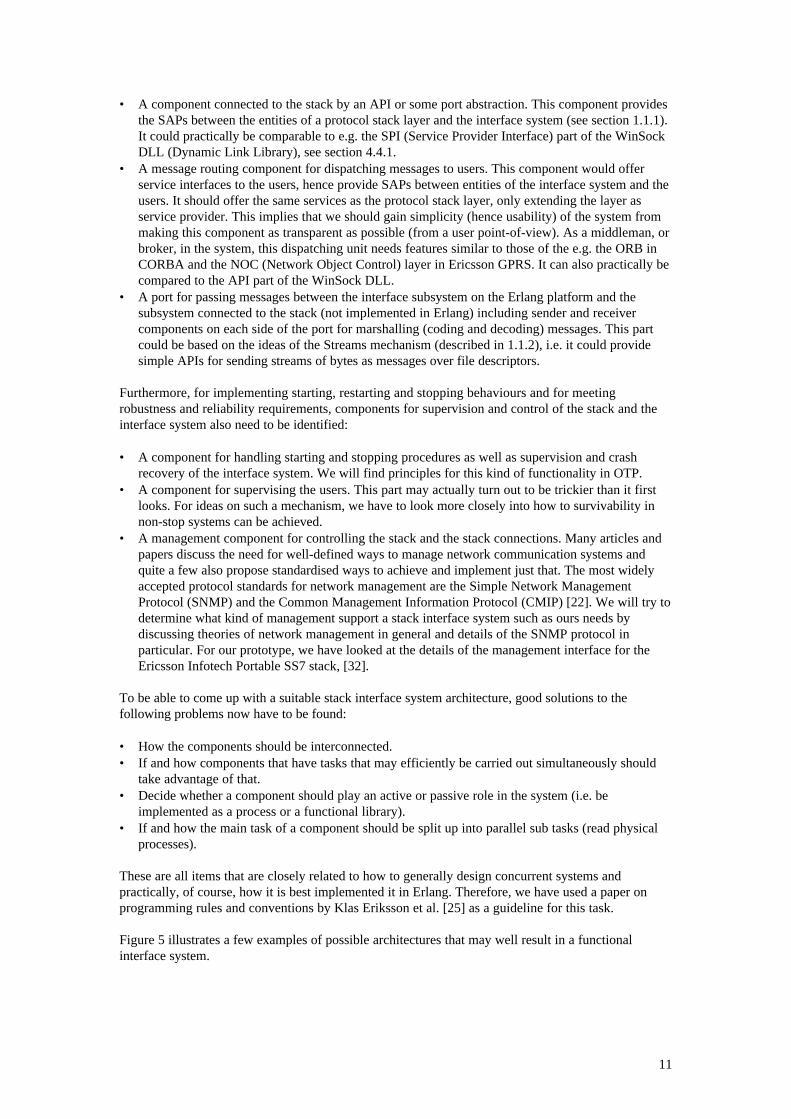
• A component connected to the stack by an API or some port abstraction. This component providesthe SAPs between the entities of a protocol stack layer and the interface system (see section 1.1.1).It could practically be comparable to e.g. the SPI (Service Provider Interface) part of the WinSockDLL (Dynamic Link Library), see section 4.4.1.
• A message routing component for dispatching messages to users. This component would offerservice interfaces to the users, hence provide SAPs between entities of the interface system and theusers. It should offer the same services as the protocol stack layer, only extending the layer asservice provider. This implies that we should gain simplicity (hence usability) of the system frommaking this component as transparent as possible (from a user point-of-view). As a middleman, orbroker, in the system, this dispatching unit needs features similar to those of the e.g. the ORB inCORBA and the NOC (Network Object Control) layer in Ericsson GPRS. It can also practically becompared to the API part of the WinSock DLL.
• A port for passing messages between the interface subsystem on the Erlang platform and thesubsystem connected to the stack (not implemented in Erlang) including sender and receivercomponents on each side of the port for marshalling (coding and decoding) messages. This partcould be based on the ideas of the Streams mechanism (described in 1.1.2), i.e. it could providesimple APIs for sending streams of bytes as messages over file descriptors.
Furthermore, for implementing starting, restarting and stopping behaviours and for meetingrobustness and reliability requirements, components for supervision and control of the stack and theinterface system also need to be identified:
• A component for handling starting and stopping procedures as well as supervision and crashrecovery of the interface system. We will find principles for this kind of functionality in OTP.
• A component for supervising the users. This part may actually turn out to be trickier than it firstlooks. For ideas on such a mechanism, we have to look more closely into how to survivability innon-stop systems can be achieved.
• A management component for controlling the stack and the stack connections. Many articles andpapers discuss the need for well-defined ways to manage network communication systems andquite a few also propose standardised ways to achieve and implement just that. The most widelyaccepted protocol standards for network management are the Simple Network ManagementProtocol (SNMP) and the Common Management Information Protocol (CMIP) [22]. We will try todetermine what kind of management support a stack interface system such as ours needs bydiscussing theories of network management in general and details of the SNMP protocol inparticular. For our prototype, we have looked at the details of the management interface for theEricsson Infotech Portable SS7 stack, [32].
To be able to come up with a suitable stack interface system architecture, good solutions to thefollowing problems now have to be found:
• How the components should be interconnected.• If and how components that have tasks that may efficiently be carried out simultaneously should
take advantage of that.• Decide whether a component should play an active or passive role in the system (i.e. be
implemented as a process or a functional library).• If and how the main task of a component should be split up into parallel sub tasks (read physical
processes).
These are all items that are closely related to how to generally design concurrent systems andpractically, of course, how it is best implemented it in Erlang. Therefore, we have used a paper onprogramming rules and conventions by Klas Eriksson et al. [25] as a guideline for this task.
Figure 5 illustrates a few examples of possible architectures that may well result in a functionalinterface system.
12
Figure 5: Examples of possible architectures
As illustrated in Figure 5, there are quite a few possible ways to interconnect the components. Bydiscussing the required and preferred stack interface system functionality in further detail, we shouldbe able to derive the appropriate interface system architecture.
2.2 Usability and the user interfaceA very important aspect of usability is that of users being able to communicate with the stack (possiblywith different layers concurrently) in a very intuitive and straightforward manner. As we mentioned insection 1.1, it’s important to put weight on the user interface. Not only may large and complexinterfaces have great negative effect on productivity of those developing a protocol stack userapplication [13], inconsistency is also easily introduced. All these factors contribute to the risk of thesystem ending up being incorrectly used. Hence, we must strive to make the system practically usefuland attractive by offering a simple, straightforward and consistent interface. Since our system shouldmerely extend the service provider - the stack layer - as far as the user interface is concerned, usabilitymay hopefully be achieved by forcing as little extra as possible of things related to the operation of oursystem on the users. The interface system should not force any explicit and unnecessary protocols ortasks on the users since this would make the code of the user service applications hard to read andunderstand. This, in turn, will result in programs that are error prone and hard to maintain.
It is a common technique to offer code templates (like C++ templates) or skeleton code (likebehaviours in OTP) to allow for generic programming. We will however not try to gain generality byproviding abstractions such as these (like application templates on top of the service interfaces, whichthe users would be required to use for building their applications). Here is a motivation:
• It is impossible for us to try to predict, or recommend, general ways to accomplish usercommunication sessions, especially since these may vary greatly depending on details such asprotocol stack type, level of the service provider, protocol specifics, etc.
1..m
1..n
U
CPPHD PH
CPPHD PH SL
SL
S S M
Erlang
1..n
U CPPHD/S PH 1..m
SL
SL
S M
Erlang
S MS
DPPH PHC
C
1..m
SL
SL
1..n
U
Erlang
U - userD - dispatcherP - portPH - port handlerC - stack connectorSL - stack layerS - supervisorM - manager
13
• The user applications will be stack interface system dependent to a much greater extent (i.e. lessgeneral and more tied to the inner workings of the interface system than to the actual stack).
• It could result in seriously restraining the expressive power of the users (closely related to the firstitem).
Instead it should be up to the users themselves to develop possible abstractions on top of the user andstack layer service interface if they prefer. The concept may be compared to Streams, which provides afew simple functions for passing data and one for control (see section 1.1.2). (It should be mentionedthat there are also functions in Streams for passing data and exercising control at the same time).Streams is a general, byte-oriented mechanism for data communication. Any type of application maybe based on it and hence the interface is simple and it leaves possible abstractions completely up to theuser to design.
It could perhaps be interesting to have a strictly typed interface between the users and the stackinterface. This could be accomplished by using IDL and IC. This would however require the user totranslate the service API into IDL and compile it using the generic server backend of IC (see section1.2.6). This could open up the interface system for communication with distributed objectsimplemented in other languages and also allow a user application based on CORBA objects tointerface (and be interfaced by) all external devices in a consistent way. It is interesting to note thatthe IDL interfaces are compiled into Erlang stub code that can be reloaded in runtime after updatedIDL interfaces have been recompiled with IC. Hence, the use of IDL for interface specification in thispart of the system does not result in the shortcomings of the static interfaces described in [18] (seesection 1.1.2).
A basic message passing user interface allows for IDL interface specification to be easily implementedon top of it. Again, our goal is to not impose unwanted requirements (or even features) on the userthat may only complicate the usage of the system. Typically, an Erlang user may see a requirementsuch as having to specify and/or use strictly typed IDL interfaces very much as an “unwanted feature”.Without giving any formal proofs, we conclude that a simple message passing interface is an approachthat is general enough for our purposes, since any type of stub code may be implemented on top of it.Hence, this is the type of user interface we will provide with our model. For example, a message maylook like:
{Primitive, Parameters}
where Primitive specifies the actual request or indication and Parameters is a list of argumentsassociated with the primitive. For concrete examples, please see section 3.3.1.2.
2.3 Message dispatching and user identificationAn essential difficulty in designing a general protocol stack interface system is to figure out how to beable to identify users in order to enable efficient routing of indicators and possible stack API returnvalues to them. The problem here is to find a user addressing scheme for the interface that will workfor different protocol stacks, stack layer protocols and physical interfaces. For input to this discussion,we should look at how a reference model like OSI approaches it from a general point of view. Weshould also look at real examples (i.e. physical stack implementations) and related work such as theErlang Test Port and the broker mechanism in e.g. CORBA or Capella [29] (see section 4.2.1).
2.3.1 A two level stack interface system modelA multiple user stack layer protocol for peer to peer communication must include some kind ofmessage routing information - something that indicates which layer user the message is intended for.This information identifies what OSI refers to as a Service Access Point (SAP). Practically, thisrouting information may be of any type (e.g. an integer or physical address), have any form (e.g.primitive data or compound) and be associated with different kinds of entities (e.g. hardware or a userprocess). A single user stack layer protocol or one that does not support concurrent user sessions,however, may not include this type of information at all. In a connection-oriented service, the routinginformation will also specify a particular user connection to the service provider. Hence, theinformation is in this case a tuple:
14
<UserId, ConnectionId>.
Or as specified in OSI:
<SAP, CEP>,
where CEP is the Connection End Point identity. The connection identity may also have any form. Itis likely to be a complex type if the service also for example provides peer to peer communication bymeans of dialogues or transactions within a connection. As far as dispatching is concerned – the useridentity (the SAP) is what is important for the stack interface system, since it will (or should) neverknow how a particular user is implemented to handle different connections, dialogues or transactionsanyway. This is an important observation, especially since connectionless services are not primitivecases (subsets) of connection-oriented ones. I.e. a user identity is what a user of a connectionless and aconnection-oriented service user have in common. A connectionless protocol will typically not specifya “void” connection identity.
In related work such as CORBA and Capella, the user (or network object) on the server side isidentified with a single data value which representation is unknown for the client (the objectreference type in CORBA and the connection identity in Capella). This value, typically of complextype, is registered and mapped to a particular object in a table (called the Interface Repository, IR, inCORBA) and is used by the ORB (the broker) for dispatching messages. Our stack interface systemshould use the same approach. It should define the type of an identity necessary for dispatchingmessages to the users (typically an Erlang process identity) and keep a table for mapping the identityvalues to the ones used in the protocol between the service user and provider. Both CORBA andCapella use a registration mechanism to maintain the mapping information. As we will discuss later,this turns out to also be the best approach for us.
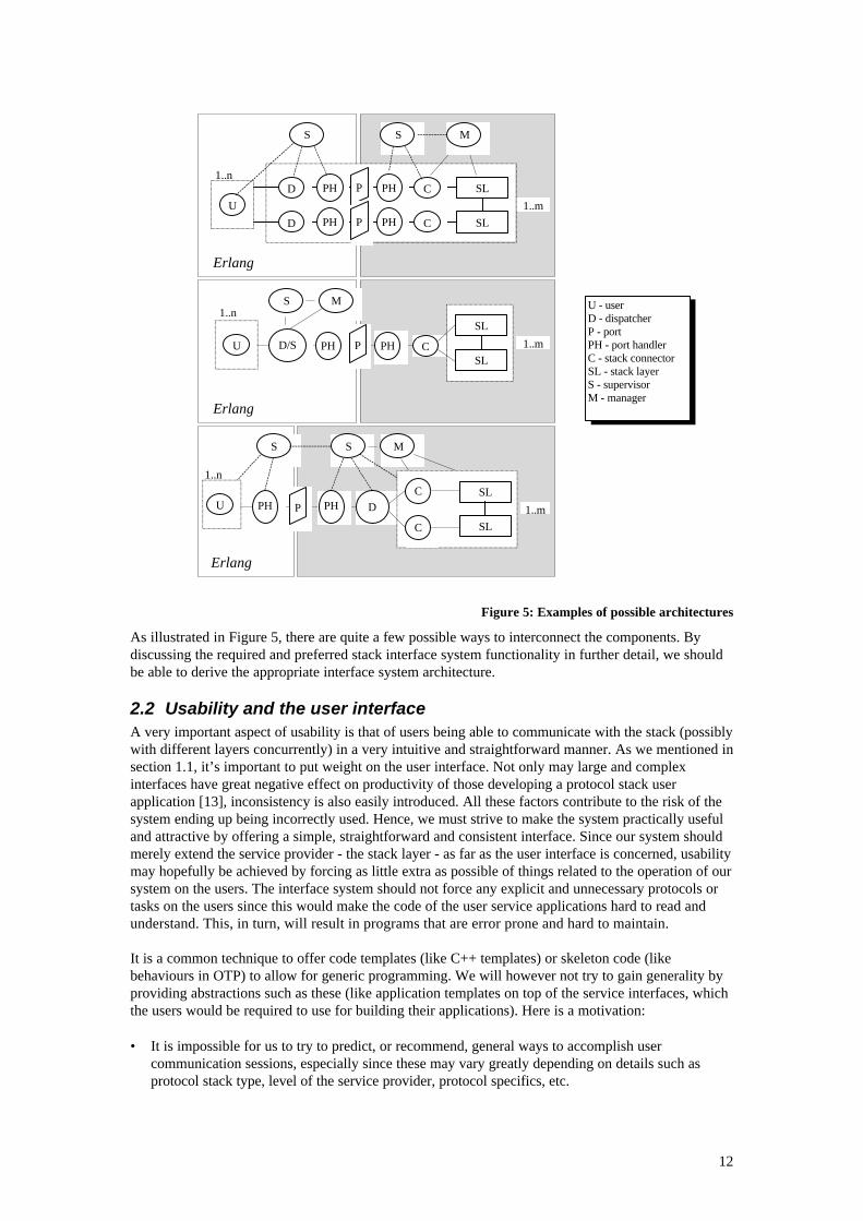
How messages may physically be transferred between the stack layers and the interface must now beconsidered. The message passing between the layer and the layer users (in this case the interfacesystem) might for example be achieved by the use of one or more port stream or message queue. Wewill denote a message channel like this a link3, to make it possible to reason more generally about it.
Figure 6: Stack links
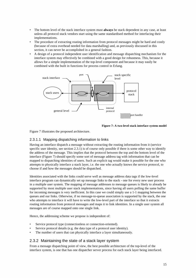
A link must physically be connected to a protocol stack layer as illustrated in Figure 6 and managedby the stack interface system. Although the link itself is a general concept, the implementation of thephysical connection to the stack must, for obvious reasons, be dependent on the stack implementation.We have already recognised the need for a protocol independent user identification and messagedispatching mechanism that works well with the stack interface system itself. A possible architecturebased on these prerequisites is to have a stack independent top level and a stack specific bottom levelof the interface system with a simple protocol between the two components. With this design it shouldbe possible to use the top level of the system with any stack, also without having to know about thestack layers it should be interfacing. Here are a few more indications that this is a suitablearchitecture:
3 This term is not in any way related to the concept of Erlang links (see 1.2.4).
Stack interface
UsersProtocol stack
Layer1
Layer2
Layer3
Links
15
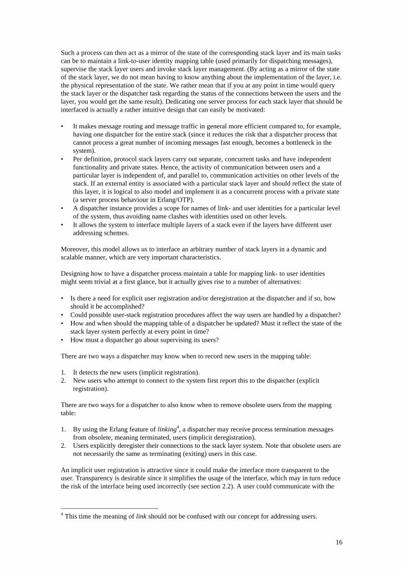
• The bottom level of the stack interface system must always be stack dependent in any case, at leastunless all protocol stack vendors start using the same standardised method for interfacing theirimplementations.
• The procedure of extracting routing information from protocol messages might be hard and costly(because of extra overhead needed for data marshalling) and, as previously discussed in thissection, it can never be accomplished in a general fashion.
• A design of a protocol independent user identification and message dispatching mechanism for theinterface system may effectively be combined with a good design for robustness. This, because itallows for a simple implementation of the top-level component and because it may easily becombined with the built in functions for process control in Erlang.
Figure 7: A two-level stack interface system model
Figure 7 illustrates the proposed architecture.
2.3.1.1 Mapping dispatching information to linksHaving an interface dispatch a message without extracting the routing information from it (servicespecific user identity, see section 2.3.1) is of course only possible if there is some other way to identifythe address of the message. This implies that the protocol between the top and the bottom level of theinterface (Figure 7) should specify some sort of message address tag with information that can bemapped to dispatching identities of users. Such an explicit tag would make it possible for the one whoattempts to physically interface a stack layer, i.e. the one who actually knows the service protocol, tochoose if and how the messages should be dispatched.
Identities associated with the links could serve well as message address data tags if the low-levelinterface program can dynamically set up message links to the stack - one for every new user processin a multiple user system. The mapping of message addresses to message queues is likely to already besupported by most multiple user stack implementations, since having all users polling the same bufferfor incoming messages is very inefficient. In this case we could simply use a 1-1 mapping between thequeues and our links. Otherwise, if no message-to-queue association is supported by the stack, the onewho attempts to interface it will have to write the low-level part of the interface so that it extractsrouting information from protocol messages and maps it to link identities. In a single user system allmessages are of course mapped onto one single link.
Hence, the addressing scheme we propose is independent of:
• Service protocol type (connectionless or connection-oriented).• Service protocol details (e.g. the data type of a protocol user identity).• The number of users that can physically interface a layer simultaneously.
2.3.2 Maintaining the state of a stack layer systemFrom a message dispatching point of view, the best possible architecture of the top-level of theinterface system, is one that has one dispatcher server process for each stack layer being interfaced.
stack users
stack specificlevel
general levelport handler
protocolstack
portstack interface
internalprotocol
16
Such a process can then act as a mirror of the state of the corresponding stack layer and its main taskscan be to maintain a link-to-user identity mapping table (used primarily for dispatching messages),supervise the stack layer users and invoke stack layer management. (By acting as a mirror of the stateof the stack layer, we do not mean having to know anything about the implementation of the layer, i.e.the physical representation of the state. We rather mean that if you at any point in time would querythe stack layer or the dispatcher task regarding the status of the connections between the users and thelayer, you would get the same result). Dedicating one server process for each stack layer that should beinterfaced is actually a rather intuitive design that can easily be motivated:
• It makes message routing and message traffic in general more efficient compared to, for example,having one dispatcher for the entire stack (since it reduces the risk that a dispatcher process thatcannot process a great number of incoming messages fast enough, becomes a bottleneck in thesystem).
• Per definition, protocol stack layers carry out separate, concurrent tasks and have independentfunctionality and private states. Hence, the activity of communication between users and aparticular layer is independent of, and parallel to, communication activities on other levels of thestack. If an external entity is associated with a particular stack layer and should reflect the state ofthis layer, it is logical to also model and implement it as a concurrent process with a private state(a server process behaviour in Erlang/OTP).
• A dispatcher instance provides a scope for names of link- and user identities for a particular levelof the system, thus avoiding name clashes with identities used on other levels.
• It allows the system to interface multiple layers of a stack even if the layers have different useraddressing schemes.
Moreover, this model allows us to interface an arbitrary number of stack layers in a dynamic andscalable manner, which are very important characteristics.
Designing how to have a dispatcher process maintain a table for mapping link- to user identitiesmight seem trivial at a first glance, but it actually gives rise to a number of alternatives:
• Is there a need for explicit user registration and/or deregistration at the dispatcher and if so, howshould it be accomplished?
• Could possible user-stack registration procedures affect the way users are handled by a dispatcher?• How and when should the mapping table of a dispatcher be updated? Must it reflect the state of the
stack layer system perfectly at every point in time?• How must a dispatcher go about supervising its users?
There are two ways a dispatcher may know when to record new users in the mapping table:
1. It detects the new users (implicit registration).2. New users who attempt to connect to the system first report this to the dispatcher (explicit
registration).
There are two ways for a dispatcher to also know when to remove obsolete users from the mappingtable:
1. By using the Erlang feature of linking4, a dispatcher may receive process termination messagesfrom obsolete, meaning terminated, users (implicit deregistration).
2. Users explicitly deregister their connections to the stack layer system. Note that obsolete users arenot necessarily the same as terminating (exiting) users in this case.
An implicit user registration is attractive since it could make the interface more transparent to theuser. Transparency is desirable since it simplifies the usage of the interface, which may in turn reducethe risk of the interface being used incorrectly (see section 2.2). A user could communicate with the
4 This time the meaning of link should not be confused with our concept for addressing users.
17
stack without being concerned with the underlying interface system at all. This design, however,causes problems that there seems to be no way around:
• The only way for a dispatcher to be able to detect new users is if there is a user-dispatcher protocolthat specifies identities, unique for each user, explicitly tagged on every message. This is probablybest achieved by providing stub code to be used for interfacing the system (not to losetransparency). But because we do not want to necessarily impose a 1-to-1 relationship betweenErlang processes and users on the application designers, tagging messages implicitly to detect newusers becomes infeasible. After all, we don’t know anything about the specific service protocols.
• Implicit user deregistration means requiring that user processes must terminate in order to bederegistered. This is an unacceptable requirement since one process may well have more than oneuser connected to, and registered at, the system (as mentioned above).
• Primitives should exist anyway for users with registered stack interface system connections whowant or need to change process identity. An example is a user application that uses a centralprocess to distribute jobs and started protocol communication sessions among processes spawnedfor the occasion.
The conclusion is that explicit registration and deregistration of users at the dispatcher is unavoidableand that it is more important to come up with an explicit registration and deregistration procedurethat is as clear and intuitive as possible for the application programmers. If using the two level stackinterface system model proposed above (having link identities as routing information), it should not benecessary to be concerned with possible user-stack registration and deregistration procedures whendesigning the interface system. (After all, that is just an example of the type of stack layer dependentfunctionality the bottom-level of the model should hide from the top-level).
To properly enable the interface system to dispatch indicators and request return values as well assupervise the users (see section 2.4.1), it should simply be required that all users register at the stacklayer dispatcher before attempting to start a communication session with the stack layer. All userscould accordingly be required to also deregister the connections when they are done. Functions forregistration and deregistration should, for simplicity, be defined in a central user interface module.
2.3.2.1 User identificationThe methods and the kind of identification data that should be used for registering a user at adispatcher depend on the way that users make contact with the stack layer. Using the interface modelproposed so far, a dispatcher process routes a message by looking up the process identity of theaddressee given the link identity of that user. A link should be set up for every new user process that isbeing connected to the system and at that time be given an identity. It should be assumed that in mostsystems, the link identities may not be chosen arbitrarily by the dispatcher but must be specified by thedesigner who know what their link identities should be in that particular system. A link identityshould perhaps, for convenience, be a reference to a file descriptor or a socket, or perhaps the designerwishes to identify the links by simple integer values for easy mapping to message queue handlers ofthe same type. Furthermore, here are a few examples of what a user might want or need to expresswhen registering:
• "I'm a user with pid P"• "I'm the user X with pid P"• "I'm the user X with pid P and I will be using my own link"• "I'm the user X with pid P and I will be using user Y's link"
The user identities (X and Y) could be on any form and pid (the process identity) is the physicaladdress of the user. The user identity might be one that is also used in the stack layer protocol, anidentity that the user maps to a stack layer protocol identity or an identity that has nothing to do withthe stack layer protocol at all. For best possible convenience for the application designers, it should beup them to decide. Since we are interfacing the users in a dynamically typed language, we don’t needto put type restrictions on the user identity types. Application designers that require a statically typedservice protocol interface may use a description language like IDL for this purpose and wrap the stackinterface system interface with the compiled stub code (see section 1.2.6). Moreover, the bottom
18
interface module may want or have to treat the user identities as aliases for "true" link identities,physical memory addresses for example. In this case there also needs to be mapping done in thebottom level module between aliases and physical link identities.
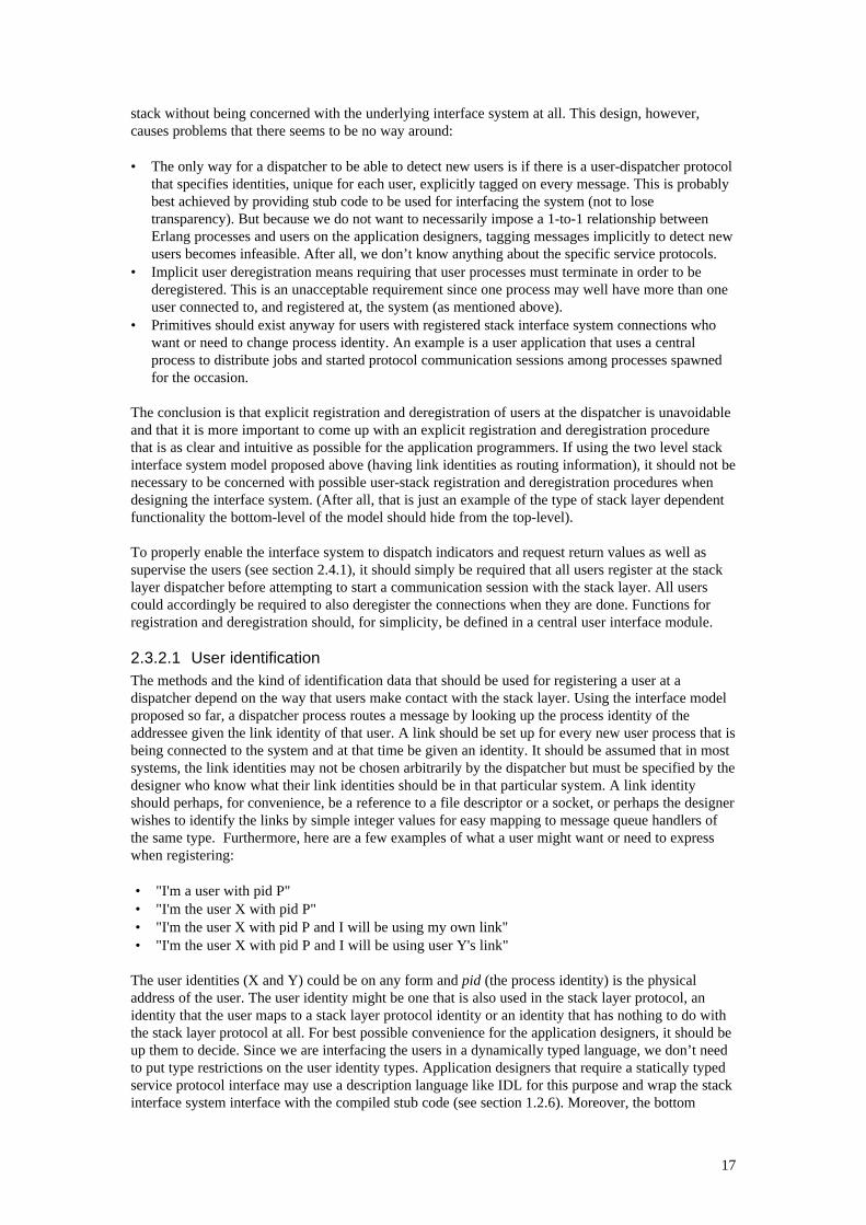
The last two examples of the registration expressions above show how users, by specifying redirection,may tell a dispatcher to route their messages to common points in a user application. By a commonpoint we mean a user whose identity other users may specify as receiver for their messages (messageswill be sent to that user process). This is illustrated in Figure 8.
Figure 8: Redirection and common point
This is merely a feature that makes the model more flexible. It enables the application designer tobuild a system with e.g. proxy server behaviour [14]. It is also possible that a user application needs tobe able to handle redirection of messages because of the addressing scheme of a particular serviceprotocol. The TCAP layer of the Ericsson Portable SS7 stack, [34], is an example of such a protocol.
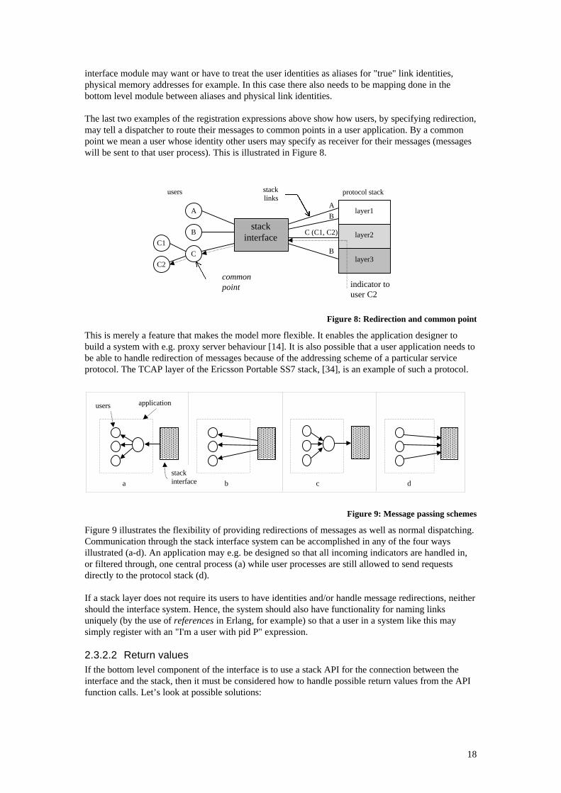
Figure 9: Message passing schemes
Figure 9 illustrates the flexibility of providing redirections of messages as well as normal dispatching.Communication through the stack interface system can be accomplished in any of the four waysillustrated (a-d). An application may e.g. be designed so that all incoming indicators are handled in,or filtered through, one central process (a) while user processes are still allowed to send requestsdirectly to the protocol stack (d).
If a stack layer does not require its users to have identities and/or handle message redirections, neithershould the interface system. Hence, the system should also have functionality for naming linksuniquely (by the use of references in Erlang, for example) so that a user in a system like this maysimply register with an "I'm a user with pid P" expression.
2.3.2.2 Return valuesIf the bottom level component of the interface is to use a stack API for the connection between theinterface and the stack, then it must be considered how to handle possible return values from the APIfunction calls. Let’s look at possible solutions:
B
C
C2
A
B
B
C (C1, C2)
indicator touser C2
layer2
A
C1
stacklinks
users
stackinterface
protocol stack
layer1
layer3
commonpoint
users application
stackinterfacea b c d
19
A test script executing on a TTCN platform sends an explicit request to retrieve the result of a testoperation previously invoked. When the Erlang Test Port receives such a request, it will send theresult back to the requesting user (the task executing the script). This means that there must exist abuffering mechanism in the Erlang Test Port that can store test results temporarily until users requestthem. In Capella, functions for invoking distributed objects are specified in the interfaces as beingeither synchronous (a generic server call using OTP terminology) or asynchronous (a generic servercast). If a function call is synchronous, the client always expects the interface function to return avalue (and it waits while the call is being executed). The underlying broker mechanism forwards thedata of the call, invokes the server object and passes the result back to the client that receives theresult as return value of the initial call. In the case of an asynchronous call, again the broker invokesthe server object but does not route a return value back to the client. (The client is of course notwaiting for one either).
It is mainly the specification of TTCN that decides the return value approach of the Erlang Test Port.For our model, requiring explicit requests for return values is not a good approach. Here are a fewdisadvantages:
• It makes the implementation of the low-level part of the system more complicated since it has toinclude a message buffering mechanism.
• It will take too long for a user to receive a return value from a previous request.• It imposes unnecessary interface system related communication on the users.
The Capella approach (which is also the one CORBA has) is more suitable for us, but since we areaiming to provide a simple message passing interface without a stub code API (see section 2.2), weneed to however discuss a somewhat different approach.
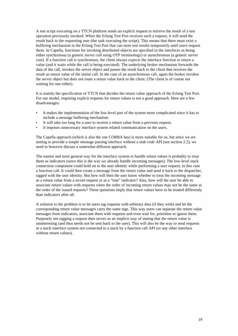
The easiest and most general way for the interface system to handle return values is probably to treatthem as indicators (since this is the way we already handle incoming messages). The low-level stackconnection component could hold on to the user identity while performing a user request, in this casea function call. It could then create a message from the return value and send it back to the dispatcher,tagged with the user identity. But how will then the user know whether to treat the incoming messageas a return value from a recent request or as a “true” indicator? Also, how will the user be able toassociate return values with requests when the order of incoming return values may not be the same asthe order of the issued requests? These questions imply that return values have to be treated differentlythan indicators after all.
A solution to the problem is to let users tag requests with arbitrary data (if they wish) and let thecorresponding return value messages carry the same tags. This way users can separate the return valuemessages from indicators, associate them with requests and even wait for, prioritise or ignore them.Purposely not tagging a request then serves as an implicit way of stating that the return value isuninteresting (and thus needs not be sent back to the user). This will also be the way to send requestsin a stack interface system not connected to a stack by a function call API (or any other interfacewithout return values).
20
Figure 10: API function return values
2.4 Control and supervisionOther issues that affect the design of the stack interface system are control and supervision. How canit be detected that a user, an interface system component or the stack itself goes down and how can itbe prevented from even happening? What must be done if a crash somewhere in the system isdetected? Designing for robustness is hard and there are many issues involved in this process. In apaper on architectural approaches to information survivability [15], the authors list faults that criticalinformation systems have to tolerate in order for them not to fail. The faults are:
• hardware degradation faults,• hardware design faults,• software faults,• faults in operational procedures,• faulty actions by operators,• changes in physical environmental conditions, and• malicious attacks.
To discuss all of these types of faults in relation to our system would be far too ambitious. Instead, wewill try to identify what faults are especially interesting to analyse from our point of view and focus onthem.
First of all, we consider hardware-related problems to be outside the scope of our thesis. The reason isthat our work is focused on the software aspects of design (mainly since Erlang is a high-levellanguage and runs on any hardware and operating system platform it is ported to). “Techniques existfor dealing with many of these types of faults. Redundant components, for example, can be configuredto deal acceptably with hardware degradation faults” [15]. OTP has the support for implementingsystems using such existing techniques and since they are general techniques, not specific for ourdesign, we will not discuss them (or how we may apply them to handle hardware faults) further.
Finding efficient and feasible ways to protect the system from deliberate attacks is very hard. Theanalysis of what is needed to ensure a high enough level of security for a system such as ours isactually enough material for a whole separate paper. Furthermore, such an analysis would have to dealwith requirements on the underlying support and mechanisms in Erlang and there has already beenwork done in this area. In the thesis on SafeErlang [23], Gustaf Naeser discusses what securityprimitives need to be implemented in Erlang for it to support safety in mobile agent applications.SSErl [24] is another work that proposes a hierarchy of nodes on the Erlang system which provide acustom context for processes in them and the use of password capabilities for values such as pids,
users API
layer2
stack
layer1
layer3
13
7
X D PH C
X, tag
2
4
5
6
1. msg: {tag, request, params}2. msg: {X, tag, request, params}3. memorize(X, tag)4. func call: request(params)5. return value: r6. msg: {X, tag, r}7. msg: {tag, r}
D: dispatcherPH: port and port handlersC: stack connection
21
ports and nodes. We will not discuss aspects of software safety and security any further in this papersince we consider these to also be outside the scope of our thesis.
The authors of [15] identify software faults to be of particular concern: “Software dependabilityremains problematic and production software continues to be a weak link in computer systems”. Wewould like to divide the software faults we may encounter in our system into two categories:
• Exceptional failures, like fatal system crashes, that may only be recovered from by having aspecific architecture for fault tolerance, e.g. redundancy by the use of a distributed database, acrash recovery mechanism that makes it possible to resume traffic on a standby node, etc.
• Minor or temporary failures of system components that must not crash or corrupt othercomponents or the system as a whole, like the unexpected termination of a user process, forexample.
OTP provides methods needed for handling the type of errors referred to in the first category above.As mentioned previously, we will not discuss general techniques such as these in this paper.Consequently, we have now narrowed down the problem area we need to focus on to be the secondcategory of faults above. By means of dependency and supervision between components, we shouldhopefully be able to handle errors such as those.
2.4.1 User supervisionIf a user terminates unexpectedly during a communication session with the stack, it could leave thedispatcher(s) and perhaps also the stack corrupt. As a result the user might, after restart, not be able toinitiate a new sessions. In the long run these problems might render the stack system useless and itwould have to be rebooted. To prevent this from happening, the stack interface system needs a way tosupervise the stack users so that it may react when a user terminates. The supervision may be realisedusing the process linking functionality of Erlang, which makes it possible for a dispatcher to receive atermination message when a user goes down. The dispatcher may then react by clearing the dataassociated with the user from its dispatching table and notify an interface system manager about theevent so that appropriate actions may be taken to update the state of the stack.
There is a problem with the linking procedure, however. The links between processes in Erlang arealways bi-directional, which means that a user linked by a dispatcher must explicitly state that it mustnot go down if the dispatcher terminates. The stack interface system will loose transparency andreliability this way. There are no good alternatives to the linking mechanism, though. A heartbeatprotocol between the user and the system, for example, is much more complicated and inefficient. Theonly way to make such a mechanism invisible to the user is by providing a kernel process for the userthat it would be required to execute its code on. This would put unacceptable restrictions on theapplication designers. Fortunately, there is a way around the problem with the links, which is the useof what we have decided to call intermediaries.
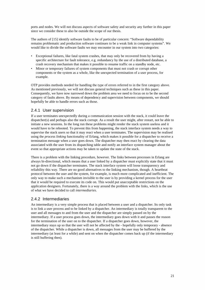
2.4.2 IntermediariesAn intermediary is a very simple process that is placed between a user and a dispatcher. Its only taskis to link a user process and to be linked by a dispatcher. An intermediary is totally transparent to theuser and all messages to and from the user and the dispatcher are simply passed on by theintermediary. If a user process goes down, the intermediary goes down with it and passes the reasonfor the termination of the user on to the dispatcher. If a dispatcher goes down, however, theintermediary stays up so that the user will not be affected by the - hopefully only temporary - absenceof the dispatcher. While a dispatcher is down, all messages from the user may be buffered by theintermediary (at least for a while) and sent on when the dispatcher comes back up (if the intermediaryis still buffering then).
22
Figure 11: Intermediaries
The true motivation for using intermediaries is that a dispatcher will be too complex to be madecompletely safe, i.e. free from all possible errors. Instead, the system must be able to restart adispatcher and restore its most recent state as quickly as possible in case of a crash. It does not matterhow quickly a dispatcher comes back up to pick up its user communication sessions if the users havealready terminated because they were linked directly by the dispatcher (and had not covered for apossible dispatcher termination event). An intermediary is meant to be simple enough that it may beassumed (or even proved) that it is free from software faults (a behaviour called Trusted Worker in[25]).
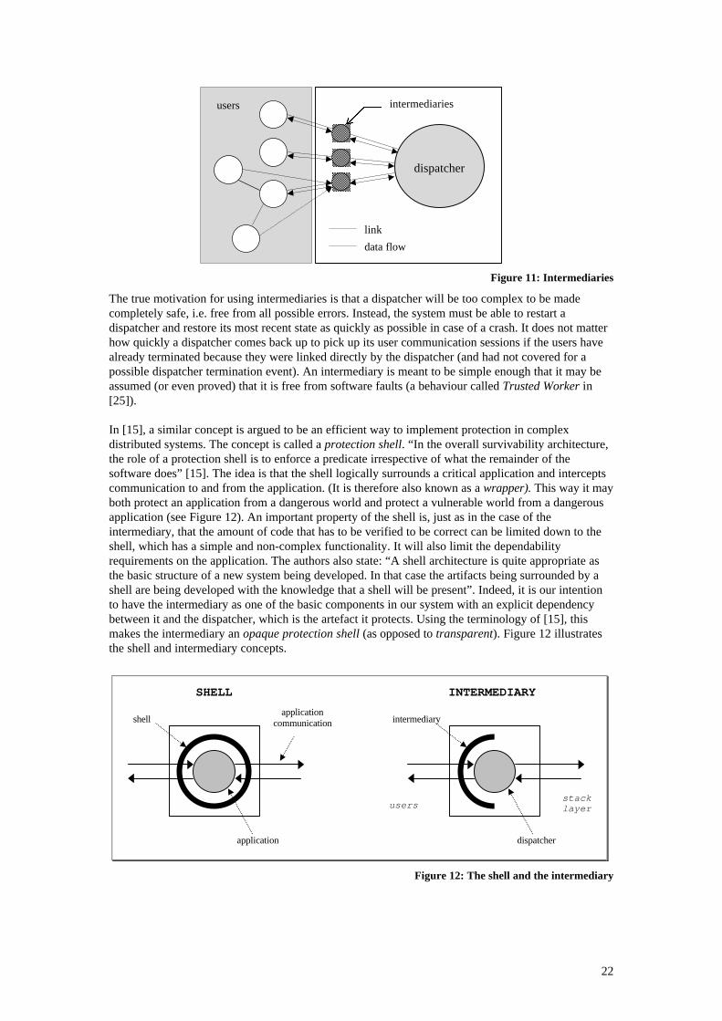
In [15], a similar concept is argued to be an efficient way to implement protection in complexdistributed systems. The concept is called a protection shell. “In the overall survivability architecture,the role of a protection shell is to enforce a predicate irrespective of what the remainder of thesoftware does” [15]. The idea is that the shell logically surrounds a critical application and interceptscommunication to and from the application. (It is therefore also known as a wrapper). This way it mayboth protect an application from a dangerous world and protect a vulnerable world from a dangerousapplication (see Figure 12). An important property of the shell is, just as in the case of theintermediary, that the amount of code that has to be verified to be correct can be limited down to theshell, which has a simple and non-complex functionality. It will also limit the dependabilityrequirements on the application. The authors also state: “A shell architecture is quite appropriate asthe basic structure of a new system being developed. In that case the artifacts being surrounded by ashell are being developed with the knowledge that a shell will be present”. Indeed, it is our intentionto have the intermediary as one of the basic components in our system with an explicit dependencybetween it and the dispatcher, which is the artefact it protects. Using the terminology of [15], thismakes the intermediary an opaque protection shell (as opposed to transparent). Figure 12 illustratesthe shell and intermediary concepts.
Figure 12: The shell and the intermediary
stacklayer
intermediary
dispatcher
INTERMEDIARY
users
users intermediaries
dispatcher
link
data flow
applicationcommunication
application
shell
SHELL
23
2.5 Stack interface system managementIn a paper on Network Management Protocols [22], the authors describe network management asactivities that involve planning, configuration, controlling, monitoring, recovering, tuning andadministration of computer networks and distributed systems. The general architecture of a networkmanagement system (NMS) includes two different roles played by nodes in the system: manager andagent. A manager acts as a control centre and an agent, which resides on a network element that hasresources to be managed, stores information about the resources and provide this to a manager via anetwork management protocol. SNMP (Simple Network Management Protocol) is a standardisedapplication-layer protocol based upon the general NMS model. It uses two techniques to make agentinformation available to the manager: polling and event reporting (where polling is most commonlyused). Data for managed resources is stored by the agent in a database called a MIB (ManagementInformation Base). The manager knows the structure of the agent MIBs and can monitor and controlthe resources by reading and modifying data in these tables.
An operator with an interface to a management control centre should be able to control and monitor aprotocol stack connected to our interface system as well as the interface system itself. For this, oursystem should provide a simple and general interface to a management component (e.g. an SNMPagent). This component should even, although we don’t know anything about its particularfunctionality (since it depends mostly on the stack we are interfacing), be a part of our model. Oursystem should be open for any type of management strategy, whether, for example, it is desirable thatstack specific runtime events are handled by an operator via an NMS, directly by the integratedmanagement component, or maybe both.
A management component should be able to handle the things no other component in the stackinterface system knows how to deal with. It is therefore important that it has a central role in themodel, but again, must be implemented by the programmers who know the details of the stack beinginterfaced (the stack layer protocols and the implementation). Two different types of managementactions can be identified:
• Actions related to the stack. For example, handling alarms, events and error messages sent fromthe stack or to tell the stack to close down a session with a specific user.
• Actions related to the stack interface system, like setting up links (see section 2.3) and associateusers with link identities, for example.
There needs to be a management component on the top Erlang level of the interface system thatshould be notified by the dispatchers when stack interface related management events occur, e.g. usersregister, users terminate or physical stack layer connections need to be reset. It is also possible that theinterface system needs a management component in the bottom level of the system that may beinvoked by the top component to perform low level actions towards the stack. It is up to the designersof the management component to choose the most appropriate architecture to fit that particularprotocol stack, should it be a central management unit for all stack layers or a concurrent one with amanagement process assigned to each stack layer dispatcher, for example.
The management component (or components) should, like the stack interface system users, be linkedby the dispatchers, possibly through intermediaries. The dispatchers must know if the managementcomponent goes down so that they may buffer messages destined for it and resume transmission whenit starts up again. The same scenario also holds the other way around.
From this point on, we will refer to the management component in our model simply as the manager.This should not be confused with the manager of NMS or SNMP described above, which of course hasa very different functionality.
2.6 Processes and function librariesIt is relevant to define what components in our so far proposed model should be implemented as activeprocesses and what should rather be passive modules, i.e. function libraries. A rule in [25] formodelling concurrent systems states: “Processes are the basic system structuring elements. But don’tuse processes and message passing when a function call can be used instead”. The motivation for this
24
rule is of course that there is extra overhead, both in terms of performance and memory usage, inconnection with using processes and message passing. Also, modelling static and statelessfunctionality as processes will only make the model confusing. Another rule in [25] states: “Use oneparallel process to model each truly concurrent activity in the real world. If there is a one-to-onemapping between the number of parallel processes and the number of truly parallel activities in thereal world, the program will be easy to understand”. Examining the suggested interface systemcomponents above and their assigned tasks, it turns out that they are all distinct actors with their ownstates, carrying out parallel activities in the interface system. This implies that they should also beimplemented as separate processes.
2.6.1 The manager module - a process or a function library?It might be tempting to have the manager implemented as a library of functions instead of as aseparate process. This way, instead of notifying a manager process by sending a message, a dispatchermay invoke a manager function and get the result from that operation back as a return value instead ofreceiving the result as a message. This turns out to be a bad solution however, since the operations ofthe manager must be able to execute in parallel with the rest of the activities going on in the stackinterface system. We can especially not afford to block traffic on a dispatcher while performingmanagement. This would not only be inefficient, but also quite impractical since the manager needsthe dispatcher to be in a running mode, sending and receiving messages, to be able to carry out itstasks.
Furthermore, the manager must be able to have its own state if this turns out to be necessary for itsfunctionality. For a passive management model, this can be realised by using persistent memory or byallowing the manager to write into tables owned by the dispatchers, which either way will not bepretty. Also, if the manager is implemented as a function library by someone else than whoimplements the interface system, it may be difficult to shield the dispatcher from faults in themanagement code that may crash the dispatcher (simply rejecting illegal management messages ismuch easier to implement).
If the manager component should be implemented as an agent for the system to be integrated in anNMS like SNMP, then it is definitely required that the agent can run on a separate process. It needs amessage based communication interface to the control centre and it needs to have access to its owntables (e.g. SNMP MIBs).
2.7 Connecting the interface system to a stackThere is no general way to connect the stack interface system to a specific stack. How the physicalconnection should be realised depends on the stack, i.e. the protocols, the implementation of the stackinterface and the OS used. Certain criteria for how the stack connection module must behave can beset up and a protocol between this module and the top level of the interface system (see section 2.3.1)can be specified, but that is as far as we can go. The behaviour of the stack connection moduledepends partly on how the stack implementation handles its incoming and outgoing messages andpartly on what the interface between the bottom and top level of the stack interface system looks like.This, in turn, depends mainly on how message dispatching is accomplished in the stack interfacesystem.
Because of the reasons described above, a detailed design of a physical stack connection componentcannot be accomplished until the specifics of the protocol stack to be interfaced are known. We will inthe next section give a brief example of how to go about designing such a component and in chapter 3,we will give a detailed design and implementation description. One of the most important purposes ofa stack layer connector is to give a stack layer the impression that a set of users are connected directlyto it, even though they are actually registered at the interface system and are communicating indirectlythrough the system.
2.7.1 A stack connection component for the TCAP layer of the Portable SS7Consider an example in which we attempt to connect our general stack interface system (with thecomponents and functionality that have been proposed so far) to the TCAP layer (see section 1.1.3) of
25
the Ericsson Infotech Portable SS7 protocol stack (written in C) [33], [34]. The TCAP process of thePortable SS7 sets up a message queue for every new TCAP user who registers at the stack and who isnot supposed to use an already existing user's queue. The TCAP process will put incoming messages,indicators, in the corresponding user queue and it is up to each user to check its own message queuefor newly arrived messages (which means that it suspends itself until one arrives). When a userreceives an indicator, it should take action by having the appropriate user defined protocol APIfunction called. When sending a request to the TCAP process, a user will simply call the protocol APIfunction that corresponds to the request. This implies that the stack connection process of the stackinterface system needs a threaded model for handling the checking of the user message queues (onethread for each queue). The user requests may be handled by a, for the connection module, centralrequesting routine that will call the corresponding API functions or the requests may indeed beperformed by the individual threads instead.
As we have already stated, there should be a well-defined internal protocol between the stackconnection component and the top-level of the interface. The stack connection component shouldtranslate incoming request messages, on a form specified by the internal protocol, into stack layer APIfunction calls for the service protocol. Analogously, indicator function calls by the stack layer system,the service protocol, should be translated into indicator messages for the internal protocol. Also, thetop level of the interface system will require that the indicator messages from the stack connectioncomponent have link identity tags attached to them (see section 2.3 for details).
The conclusion is that since the stack connection component must translate between the internal andthe TCAP service protocol, as well as adapt to the Portable SS7 implementation of the TCAP service,it must implement the following:
• functionality for converting internal protocol messages to TCAP service function calls,• functionality for converting TCAP service function calls to internal protocol messages, and• association between link identities and threads.
It should be a rather straightforward task to come up with a suitable design for a Portable SS7 stackconnection component from the analysis and conclusion above. In section 3.4.2 we verify this bypresenting a detailed design and implementation of it. The example here may also serve as a generalproposal for how to reason when trying to come up with a connection component design for anyspecific stack and stack layer implementation.
2.8 Running the stack interface system in a distributed environmentA paper titled Network Control as a Distributed Object Application [11] describes a distributedprocessing environment (DPE) for real-time multimedia applications. The paper presents an object-based hybrid interface model for distributed communication. The idea of the DPE is to have aconnection server configured to provide either a CORBA or a TCP/IP socket interface, or both, toallow the client objects to choose the means of distributed communication:
• a high-level interface with features such as object location transparency, and/or• a low-level interface for high performance,depending on the type of application. For serving client objects on a Java platform, it turns out to bean efficient solution to use a proxy server architecture for the DPE. The DPE uses an ORB on theJava platform to forward client requests to a proxy server, which in turn forwards the requests to thereal connection server, implemented e.g. in C.
Instead of comparing the functionality, service and interface approach of our stack interface system tothat of the DPE presented in [11], we believe it is more interesting to consider how our stack interfacesystem could be an integrated part of such a system. It is, after all, very likely that our system is to beused by large applications that require many different types of interfaces and services for distributedcommunication. There are, of course, a very large number of different ways to design suchmiddleware. For this reason we need to look at how we may generally prepare our interface system torun in distributed environment. This is important for the flexibility, usability and even efficiency ofthe stack interface system.
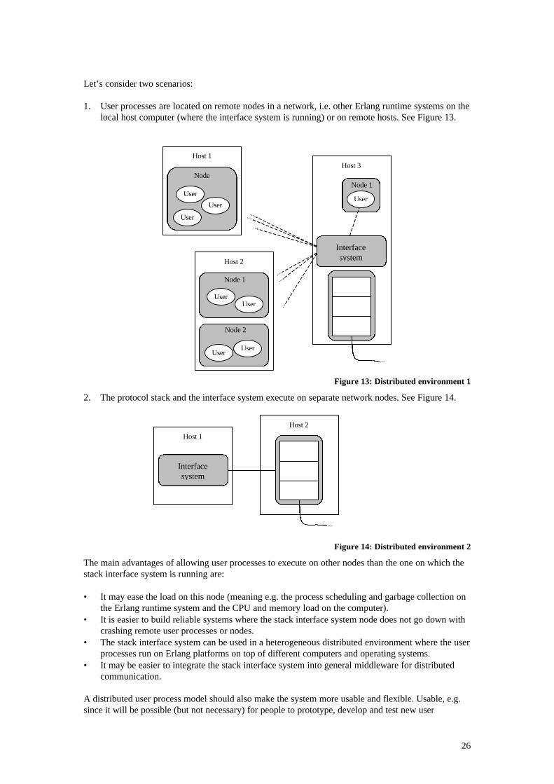
26
Let’s consider two scenarios:
1. User processes are located on remote nodes in a network, i.e. other Erlang runtime systems on thelocal host computer (where the interface system is running) or on remote hosts. See Figure 13.
Figure 13: Distributed environment 1
2. The protocol stack and the interface system execute on separate network nodes. See Figure 14.
Figure 14: Distributed environment 2
The main advantages of allowing user processes to execute on other nodes than the one on which thestack interface system is running are:
• It may ease the load on this node (meaning e.g. the process scheduling and garbage collection onthe Erlang runtime system and the CPU and memory load on the computer).
• It is easier to build reliable systems where the stack interface system node does not go down withcrashing remote user processes or nodes.
• The stack interface system can be used in a heterogeneous distributed environment where the userprocesses run on Erlang platforms on top of different computers and operating systems.
• It may be easier to integrate the stack interface system into general middleware for distributedcommunication.
A distributed user process model should also make the system more usable and flexible. Usable, e.g.since it will be possible (but not necessary) for people to prototype, develop and test new user
User
User
User
Node
Host 1
UserUser
Node 1
Host 2
Node 2
UserUser
User
Node 1
Host 3
Interfacesystem
Host 1
Interfacesystem
Host 2
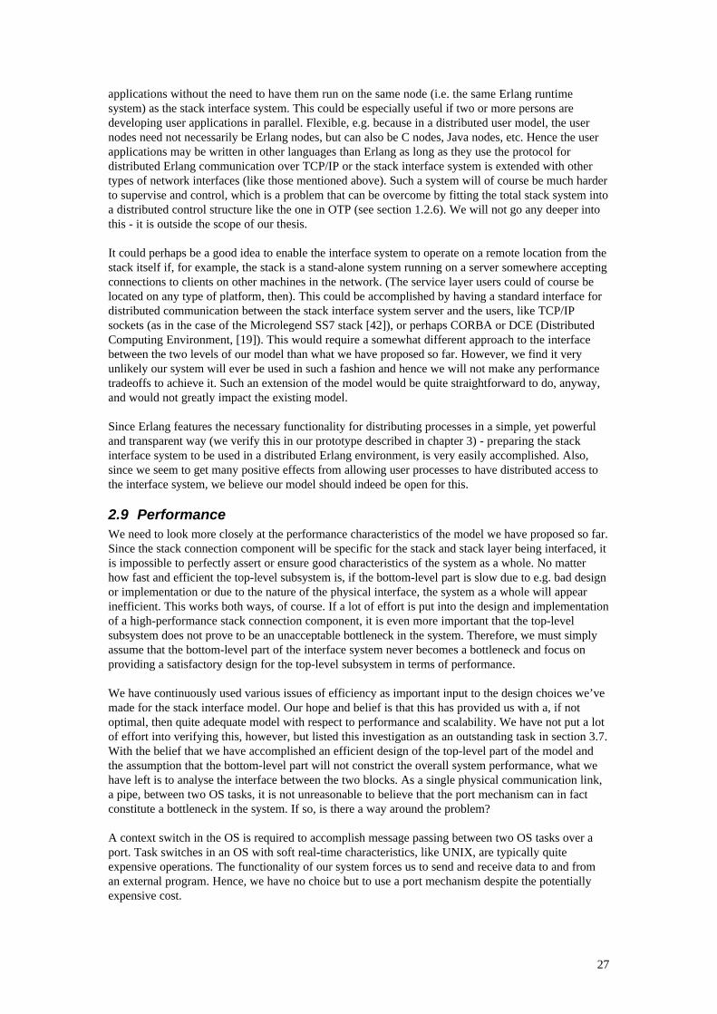
27
applications without the need to have them run on the same node (i.e. the same Erlang runtimesystem) as the stack interface system. This could be especially useful if two or more persons aredeveloping user applications in parallel. Flexible, e.g. because in a distributed user model, the usernodes need not necessarily be Erlang nodes, but can also be C nodes, Java nodes, etc. Hence the userapplications may be written in other languages than Erlang as long as they use the protocol fordistributed Erlang communication over TCP/IP or the stack interface system is extended with othertypes of network interfaces (like those mentioned above). Such a system will of course be much harderto supervise and control, which is a problem that can be overcome by fitting the total stack system intoa distributed control structure like the one in OTP (see section 1.2.6). We will not go any deeper intothis - it is outside the scope of our thesis.
It could perhaps be a good idea to enable the interface system to operate on a remote location from thestack itself if, for example, the stack is a stand-alone system running on a server somewhere acceptingconnections to clients on other machines in the network. (The service layer users could of course belocated on any type of platform, then). This could be accomplished by having a standard interface fordistributed communication between the stack interface system server and the users, like TCP/IPsockets (as in the case of the Microlegend SS7 stack [42]), or perhaps CORBA or DCE (DistributedComputing Environment, [19]). This would require a somewhat different approach to the interfacebetween the two levels of our model than what we have proposed so far. However, we find it veryunlikely our system will ever be used in such a fashion and hence we will not make any performancetradeoffs to achieve it. Such an extension of the model would be quite straightforward to do, anyway,and would not greatly impact the existing model.
Since Erlang features the necessary functionality for distributing processes in a simple, yet powerfuland transparent way (we verify this in our prototype described in chapter 3) - preparing the stackinterface system to be used in a distributed Erlang environment, is very easily accomplished. Also,since we seem to get many positive effects from allowing user processes to have distributed access tothe interface system, we believe our model should indeed be open for this.
2.9 PerformanceWe need to look more closely at the performance characteristics of the model we have proposed so far.Since the stack connection component will be specific for the stack and stack layer being interfaced, itis impossible to perfectly assert or ensure good characteristics of the system as a whole. No matterhow fast and efficient the top-level subsystem is, if the bottom-level part is slow due to e.g. bad designor implementation or due to the nature of the physical interface, the system as a whole will appearinefficient. This works both ways, of course. If a lot of effort is put into the design and implementationof a high-performance stack connection component, it is even more important that the top-levelsubsystem does not prove to be an unacceptable bottleneck in the system. Therefore, we must simplyassume that the bottom-level part of the interface system never becomes a bottleneck and focus onproviding a satisfactory design for the top-level subsystem in terms of performance.
We have continuously used various issues of efficiency as important input to the design choices we’vemade for the stack interface model. Our hope and belief is that this has provided us with a, if notoptimal, then quite adequate model with respect to performance and scalability. We have not put a lotof effort into verifying this, however, but listed this investigation as an outstanding task in section 3.7.With the belief that we have accomplished an efficient design of the top-level part of the model andthe assumption that the bottom-level part will not constrict the overall system performance, what wehave left is to analyse the interface between the two blocks. As a single physical communication link,a pipe, between two OS tasks, it is not unreasonable to believe that the port mechanism can in factconstitute a bottleneck in the system. If so, is there a way around the problem?
A context switch in the OS is required to accomplish message passing between two OS tasks over aport. Task switches in an OS with soft real-time characteristics, like UNIX, are typically quiteexpensive operations. The functionality of our system forces us to send and receive data to and froman external program. Hence, we have no choice but to use a port mechanism despite the potentiallyexpensive cost.
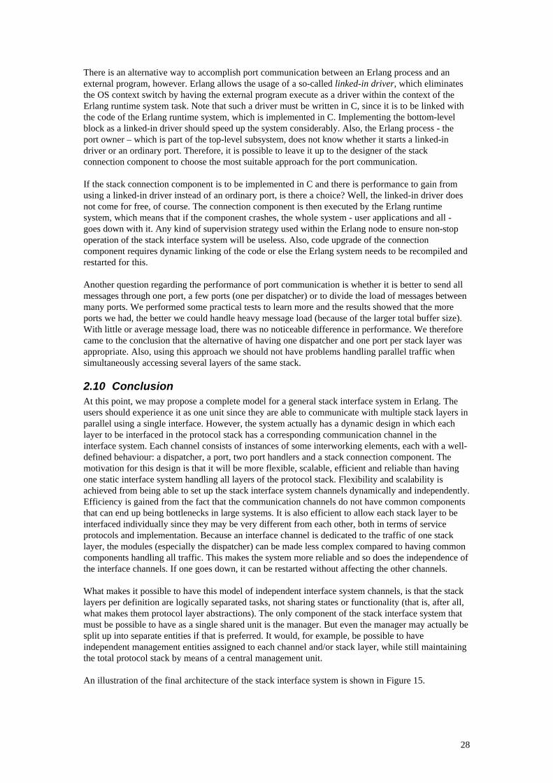
28
There is an alternative way to accomplish port communication between an Erlang process and anexternal program, however. Erlang allows the usage of a so-called linked-in driver, which eliminatesthe OS context switch by having the external program execute as a driver within the context of theErlang runtime system task. Note that such a driver must be written in C, since it is to be linked withthe code of the Erlang runtime system, which is implemented in C. Implementing the bottom-levelblock as a linked-in driver should speed up the system considerably. Also, the Erlang process - theport owner – which is part of the top-level subsystem, does not know whether it starts a linked-indriver or an ordinary port. Therefore, it is possible to leave it up to the designer of the stackconnection component to choose the most suitable approach for the port communication.
If the stack connection component is to be implemented in C and there is performance to gain fromusing a linked-in driver instead of an ordinary port, is there a choice? Well, the linked-in driver doesnot come for free, of course. The connection component is then executed by the Erlang runtimesystem, which means that if the component crashes, the whole system - user applications and all -goes down with it. Any kind of supervision strategy used within the Erlang node to ensure non-stopoperation of the stack interface system will be useless. Also, code upgrade of the connectioncomponent requires dynamic linking of the code or else the Erlang system needs to be recompiled andrestarted for this.
Another question regarding the performance of port communication is whether it is better to send allmessages through one port, a few ports (one per dispatcher) or to divide the load of messages betweenmany ports. We performed some practical tests to learn more and the results showed that the moreports we had, the better we could handle heavy message load (because of the larger total buffer size).With little or average message load, there was no noticeable difference in performance. We thereforecame to the conclusion that the alternative of having one dispatcher and one port per stack layer wasappropriate. Also, using this approach we should not have problems handling parallel traffic whensimultaneously accessing several layers of the same stack.
2.10 ConclusionAt this point, we may propose a complete model for a general stack interface system in Erlang. Theusers should experience it as one unit since they are able to communicate with multiple stack layers inparallel using a single interface. However, the system actually has a dynamic design in which eachlayer to be interfaced in the protocol stack has a corresponding communication channel in theinterface system. Each channel consists of instances of some interworking elements, each with a well-defined behaviour: a dispatcher, a port, two port handlers and a stack connection component. Themotivation for this design is that it will be more flexible, scalable, efficient and reliable than havingone static interface system handling all layers of the protocol stack. Flexibility and scalability isachieved from being able to set up the stack interface system channels dynamically and independently.Efficiency is gained from the fact that the communication channels do not have common componentsthat can end up being bottlenecks in large systems. It is also efficient to allow each stack layer to beinterfaced individually since they may be very different from each other, both in terms of serviceprotocols and implementation. Because an interface channel is dedicated to the traffic of one stacklayer, the modules (especially the dispatcher) can be made less complex compared to having commoncomponents handling all traffic. This makes the system more reliable and so does the independence ofthe interface channels. If one goes down, it can be restarted without affecting the other channels.
What makes it possible to have this model of independent interface system channels, is that the stacklayers per definition are logically separated tasks, not sharing states or functionality (that is, after all,what makes them protocol layer abstractions). The only component of the stack interface system thatmust be possible to have as a single shared unit is the manager. But even the manager may actually besplit up into separate entities if that is preferred. It would, for example, be possible to haveindependent management entities assigned to each channel and/or stack layer, while still maintainingthe total protocol stack by means of a central management unit.
An illustration of the final architecture of the stack interface system is shown in Figure 15.
29
Figure 15: The stack interface model
StackUsersmanager supervisor
I
D PH PHP SLCI
I: intermediaryD: dispatcherPH: port handlerP: portSLC: stack layer
connector
Channels
30
3. Implementation of the general stack interface system modelThis section describes an implementation of the stack interface system model that was proposed inchapter 2. As explained there, the theoretical model has two levels of abstraction:
• The top level, which is protocol stack independent.• The bottom level, which is specific for a certain protocol stack.
When it comes down to details of implementation, however, the interface system could actually beregarded as a model of three abstraction levels. In between the two layers mentioned above, there hasto be a middle layer that is stack independent, but language dependent. This is natural since there hasto be a port handling component on the side of the port that is to be connected to the stack. Thiscomponent has the general task of sending and receiving binary data packages on Erlang's externalformat (or something similar) to and from the port. Hence, the behaviour makes it logically belong tothe top level of the theoretical interface system, but the language dependency makes it practicallybelong to the bottom level. We will instead think of it as a middle level of abstraction for theimplementation since this port handling component will be using well defined protocols in "bothends", i.e. the port protocol in one end and the protocol between this and the stack connectioncomponent in the other. Also, this middle stack interface system level component would not have tobe rewritten if one replaced or modified the stack, as long as the new stack was written in the samelanguage (C in the case of this implementation).
Figure 15: The implemented model
The implementation will serve both as an example of how a general stack interface system in Erlangmay be realised and also how the interface system may actually be physically connected to an existingproduct, namely the Ericsson Infotech Portable SS7 stack. For details on this protocol stack we havebeen using references [32]-[40].
3.1 Implementation of the stack interface system channel componentsAs described in the conclusion of chapter 2, the interface system should consist of a number ofchannels corresponding to the (used) layers of the stack that the interface system is connected to. Theconcept is illustrated in Figure 16. The channels are instances of an interface system channelprototype (specified by the channel component modules) and are being set up and taken downdynamically by a main start-up process, the supervisor5. This section describes how we haveimplemented the interface system channel components.
5 This supervisor should not be confused with the OTP supervisor behaviour.
stack users
ERLANG
protocol stackdependent
protocol stackindependent
port handler
protocolstack
port
C (lang. dependent)
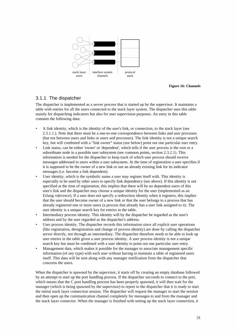
31
Figure 16: Channels
3.1.1 The dispatcherThe dispatcher is implemented as a server process that is started up by the supervisor. It maintains atable with entries for all the users connected to the stack layer system. The dispatcher uses this tablemainly for dispatching indicators but also for user supervision purposes. An entry in this tablecontains the following data:
• A link identity, which is the identity of the user's link, or connection, to the stack layer (see2.3.1.1.). Note that there must be a one-to-one correspondence between links and user processes(but not between users and links or users and processes). The link identity is not a unique searchkey, but will combined with a "link owner” status (see below) point out one particular user entry.
• Link status, can be either 'owner' or 'dependent', which tells if the user process is the root or asubordinate node in a possible user subsystem (see common points, section 2.3.2.1). Thisinformation is needed for the dispatcher to keep track of which user process should receivemessages addressed to users within a user subsystem. At the time of registration a user specifies ifit is supposed to be the owner of a new link or use an already existing link for its indicatormessages (i.e. become a link dependent).
• User identity, which is the symbolic name a user may register itself with. This identity isespecially to be used by other users to specify link dependency (see above). If this identity is notspecified at the time of registration, this implies that there will be no dependent users of thisuser's link and the dispatcher may choose a unique identity for the user (implemented as anErlang reference). If a user does not specify a redirection identity when it registers, this impliesthat the user should become owner of a new link or that the user belongs to a process that hasalready registered one or more users (a process that already has a user link assigned to it). Theuser identity is a unique search key for entries in the table.
• Intermediary process identity. This identity will by the dispatcher be regarded as the user'saddress and by the user regarded as the dispatcher's address.
• User process identity. The dispatcher records this information since all explicit user operations(like registration, deregistration and change of process identity) are done by calling the dispatcherserver directly, not through an intermediary. The dispatcher therefore needs to be able to look upuser entries in the table given a user process identity. A user process identity is not a uniquesearch key but must be combined with a user identity to point out one particular user entry.
• Management data, which makes it possible for the manager to associate management specificinformation (of any type) with each user without having to maintain a table of registered usersitself. This data will be sent along with any manager notification from the dispatcher thatconcerns the users.
When the dispatcher is spawned by the supervisor, it starts off by creating an empty database followedby an attempt to start up the port handling process. If the dispatcher succeeds to connect to the port,which means that the C port handling process has been properly spawned, it will then wait for themanager (which is being spawned by the supervisor) to report to the dispatcher that it is ready to startthe initial stack layer connection session. The dispatcher will request the manager to start the sessionand then open up the communication channel completely for messages to and from the manager andthe stack layer connector. When the manager is finished with setting up the stack layer connection, it
protocolstack
interface systemchannels
stack layerusers
32
will send the result of this operation back to the dispatcher. If the operation was successful, thedispatcher will register the link and user identities (that should not clash with the identities of the realusers) reserved by the manager and then go into an idle mode (i.e. wait for incoming messages in await-receive loop). Note that if any of the initial steps fail, the dispatcher will simply terminate andleave it up to the supervisor to possibly attempt a restart sequence. Within the wait-receive loop, thereare five different types of messages that the dispatcher will handle:
• user requests, i.e. registration, deregistration and change of process identity,• management requests and results,• supervisor requests,• stack layer protocol messages from users, the stack layer or the manager, and• process termination messages (exit signals).
How the dispatcher deals with user request messages as well as with management result messages,process termination messages and stack layer protocol messages will be explained in the proceedingsections. As for management requests, the only one the dispatcher will handle in the currentimplementation is for changing management data for a specific user entry in the dispatching table.This request must be handled by the dispatcher since it should be up to the manager to decide whatthe management data for the user should be at any point in time. The supervisor can request thedispatcher to terminate or to send back information about the status of the dispatcher (e.g. a list ofpermanently and temporarily registered users).
3.1.1.1 Handling user registration and deregistration requestsWhen a user sends a registration request to the dispatcher, the dispatcher must notify the manager sothat a new link to the stack layer process may be set up. The dispatcher must not block other activeuser communication sessions while waiting for the manager to perform its operation, so instead thedispatcher sends its request, goes back into the idle state and later responds to the registration resultmessage that comes from the manager. While the manager deals with a certain registration, thedispatcher has the name, link and process identity of the user temporarily registered. This way it ispossible to avoid identity clashes with other registering users. If the result message from the managerindicates a successful registration, the concerned user will have its registration status changed fromtemporarily to permanent (i.e. it will be recorded in the dispatching table). An intermediary will thenbe assigned to it - either an existing one that has already been assigned to the user process or a newone that will be created and linked at this point. If the registration fails, an appropriate error messagetelling the reason for failure will be sent back to the user. Thus, as a result of attempting to register anew communication session, the user will either receive an intermediary process identity (to beregarded as the actual stack layer dispatcher) or an error message.
The deregistration procedure follows the same pattern as for registration, with the main differencethat if a user deregistration succeeds, the physical link will have been taken down by the manager andthe dispatching table entry for the user will, of course, be deleted instead of recorded. The dispatcherwill in the current implementation only issue a warning if a stack layer link owner deregisters whilethere are still active user sessions dependent of the link in question.
3.1.1.2 Handling requests for changing user process identitiesSince user process identities are only of interest to the dispatcher for spawning intermediaries, there isno need for the dispatcher to notify the manager when a user changes its process identity. Thedispatcher will require that a user changes its process identity to one that is not already registered orthe user needs to have the same stack layer link identity as the user(s) who are already registered withthe user's new process identity. (Consequently, the user will already have to be a dependent of thelink). A new intermediary process will be spawned and assigned to the new user process if the identityof the process is not already registered, in which case an already existing intermediary will besupplied to the user.
33
3.1.1.3 Process termination messagesThe dispatcher will be linked to all processes that it communicates with, the intermediaries, themanager and the port handler. If a linked process terminates, the dispatcher will receive an exitmessage that identifies the process and the reason for termination. If a process terminates normally,i.e. if it has been shut down by the dispatcher or the supervisor, the dispatcher will receive an exitmessage from the process link in question that indicates normal termination. An exit message of thistype is simply ignored by the dispatcher.
If the port handler terminates abnormally, the dispatcher will attempt to start up a new port handlingprocess and have the manager reset the stack layer connection. The manager will be requested toinitiate a new stack connection procedure through a reset message from the dispatcher that includesall the necessary stack layer link information that the dispatcher has recorded. When the new stacklayer connection procedure is completed, the stack layer link identities may have changed andtherefore the entries in the dispatcher's dispatching table must be updated. If the manager terminatesabnormally, it should be restarted by the supervisor. Since the manager is such a central component inthe system, it is recommended that when the dispatcher realises that the manager is down, it shouldwait for it to come back up again and when it does, resume its normal activities. In the currentimplementation, however, the dispatcher only issues a warning if the manager goes down and thenimmediately resumes its normal activities. This means that the system in the case of a manager crashwill be unstable and very unpredictable, which is of course an unacceptable behaviour. This is asubject for the next revision of the system.
If the dispatcher receives an exit message from an intermediary, it means that a user process hasterminated abnormally and the interface system must take appropriate action (see section 2.4.1). Themanager will be requested by the dispatcher to clean the stack layer process from any data that thedead users may have left behind. The dispatcher will send along the necessary data of the affectedusers (user and link identities and management data) with the cleaning request. As in the case of userregistration and deregistration, other user sessions should not be blocked while the manager performsits operation. Therefore, the dispatcher will return to its idle mode immediately after it has sent thecleaning request to the manager and later respond to a cleaning result message from the manager.When the manager's cleaning operation is finished and the dispatcher has received the result, allentries of the users affected by the process termination will be removed from the dispatcher'sdispatching table. The dispatcher will in the current implementation issue a warning if there are anydependants of the stack layer link of the process that has gone down.
3.1.1.4 Stack layer protocol messagesStack layer protocol messages that come in to the dispatcher are either user requests or return valuesand indicators from the stack layer process. The messages used by the management are also counted tothis group. The first-mentioned type of messages come in via the intermediaries while the latter comein via the port handler. The requests are tagged with the corresponding stack layer link identities(found in the dispatching table) and sent on to the port handler for port protocol conversion andtransmission. The indicators and return values should be passed on to the rightful users. This is doneby looking up the corresponding intermediary identities in the dispatching table, given the stack layerlink identities.
3.1.2 The intermediaryWhen spawned by the dispatcher, the intermediary is given the identity of the user process that it hasbeen assigned to represent. The intermediary will start off by linking the specified user process andthen go into a loop and wait for messages to forward from the user to the dispatcher or the other wayaround. The intermediary will also trap exit signals from the user or the dispatcher. If a usertermination message is received, the intermediary will also terminate and pass on the reason fortermination to the dispatcher.
3.1.3 The Erlang port handlerThe port handling process on the Erlang side of the interface system (simply referred to as the porthandler in this section) is spawned by the dispatcher. It starts off by, in turn, trying to spawn and
34
make connection with a port handling process on the other side of the port, in this case written in C(therefore referred to as the C port handler). The port handler will, if the connection succeeds, send a'ready' signal back to the dispatcher and then go into a loop and wait for incoming messages from thedispatcher or from the port. If the connection fails the port handler will simply exit with connectionfailure as the reason for termination.
3.1.3.1 Receiving messages from the port or the dispatcherWhen the port handler is in its idle mode, it will expect to receive messages from the dispatcher orfrom the port. Messages from the dispatcher may be stack layer protocol data, a shut down request oran exit signal. The stack layer protocol messages are converted into binary form and transmitted to theC port handler. A shut down request results in the port handler shutting down the port and thenexiting with a normal 'shutdown' reason for termination.
A message received from the port is either one that should be forwarded to the dispatcher or an exitsignal that indicates that the port is down. If the port goes down, the port handler also terminates,passing on the reason for the port crash to the dispatcher. All other messages will be converted from abinary format to Erlang terms and sent on to the dispatcher.
3.2 Implementation of the central interface system componentsThe central components of the stack interface system are the supervisor and the manager. Belowfollows a detailed description of how they have been implemented.
3.2.1 The supervisorThe supervisor process should, when activated, be provided with a data structure that specifies thenames of the stacks and stack layers that it should control. The user identities for each interfacesystem manager that should initially be reserved in the dispatching tables of the dispatchers (possiblywith redirections) may also be specified in this structure. It is possible to have the supervisor start upand control interface systems for more than one stack at the same time. Since the supervisor spawnsnew instances of the same manager prototype for every stack interface system, having one supervisorcontrol multiple interface systems will only make sense if:
• they are for the same type of stack,• the manager module is implemented in a generic (one module handles more than one type of
stack) fashion, or• the manager is implemented in a polymorphic (stack specific management processes may be
spawned dynamically) fashion.
Note that when the supervisor is used to control more than one interface system it is not entirelycorrect to call it a component of the interface system, but its behaviour motivates referring to it as thatanyway.The supervisor will initially attempt to start up the stack interface systems by activating and linkingtheir stack layer dispatchers and the manager for each interface system. The supervisor requires thateach and every start up session is successful. If it detects a start up failure (indicated by an error returnvalue or an exit signal) any time during the activation of the dispatchers and the managers, thesupervisor will shut down all previously activated subsystems and terminate. There is a global ETStable created in the name of each stack interface system. In these tables the interface system dispatchernames and process identities are recorded (a dispatcher is preferably named after its correspondingstack layer). Also the process identity of each interface system manager is recorded in thecorresponding table. These tables only serve one true purpose, which is that users may registersymbolically at the stack layers by using these tables indirectly through the registration primitives, seesection 3.3.1 below. Without these tables, the users would have to register through the supervisor. Theinformation in these tables is also used by the supervisor for shutting down all stack layer systems.Also, although this functionality has not yet been implemented, the information in the global ETStables could be used by the supervisor when performing crash recovery (if a dispatcher or a managergoes down), or perhaps when rebooting or shutting down individual interface systems (automaticallyor on demand).
35
If the start up phase is successful, the supervisor goes into a loop. In this loop the supervisor expects toreceive a request for either shutting down all stack interface systems (and itself as well) or forcollecting status information from all dispatchers. The supervisor will also trap exit signals from anylinked component that has terminated.
The shut down procedure simply iterates through the list of stack interface systems and sends'shutdown' messages to all components (i.e. the dispatchers and the manager) in the respectivesystems. The supervisor will receive a 'ready' signal from a component when its shut down sequence isfinished and its next step is termination. This enables the supervisor to take down the systems in anorderly fashion. Note that a component may already have terminated at this point, which could be thereason the supervisor is shutting down the system in the first place (as in the case of failure during thesupervisor's start up routine, mentioned earlier). In this case the component will not respond to theshut down request so the supervisor will eventually time out while waiting for the 'ready' signal. Theshut down sequence may then continue and the supervisor will finally terminate as well.
When the supervisor receives a request for status information about all interface systems, it will inturn send the corresponding requests to all dispatchers, having them send back status reports andfinally forward a complete list of the data collected to whoever requested it. This makes it possible toinvestigate the state of the system at any point in time, e.g. for debugging purposes.
The supervisor will trap an exit signal from any dispatcher or manager that goes down. It is howevernot yet defined how the supervisor should react when it is notified of the termination of a linkedcomponent. This is the subject of the next revision of the interface system. A preferable action to takewould be to try to restart the component in question by initiating a restart sequence implemented inthe component. If the restart was successful, it would then be up to the component to announce itsexistence and new process identity to all actors in the system that have been affected by the crash (e.g.a dispatcher would notify the manager, the port handler and the intermediaries).
3.2.2 The managerThe manager module has been written as a template in the sense that it is prepared to send and receiveall possible requests and notifications to and from dispatchers and the supervisor (i.e. these protocolshave been implemented), but no meaningful stack management actions have been implemented as ofnow. By using this module it should hopefully be a rather straightforward task to implement a fullyfunctional manager for someone who knows the management details for the particular stackimplementation. The manager registers one or more reserved user identities at the dispatchers atsystem start-up time and sets up interface system links for itself. From that point on the manager cansend and receive protocol messages to and from the stack (requests and indicators) just as if it was anormal user. The current manager module serves as a template for systems connected to one stackonly. The module needs to be modified and/or extended if:
• The manager should be integrated as an agent in a management system such as SNMP (see thediscussion in section 2.5).
• The manager needs to be able to handle a system with connections to more than one stack. A quiteextensive implementation of the manager is probably needed if it is necessary to have a generic orpolymorphic functionality to also handle different types of stacks (as mentioned in section 3.2.1above). If the manager needs to have a polymorphic behaviour, this is best accomplished byspawning a stack specific manager process dynamically for each stack in the system at start-uptime.
• It is desirable to have one manager process associated with each stack layer channel.
It may very well be desirable to have a distributed manager runtime system that consists of onemanager process per stack layer and dispatcher. This design could be motivated by:
• Better performance in systems that have many users frequently registering and deregistering (or inany other way invoking the manager) at more than one layer of the stack simultaneously.
36
• The stack layer processes and the corresponding dispatchers represent parallel activities in thestack system (the latter are responsible for invoking the manager).
• It may result in a more logical structure of the code, hence a system that is easier to understandand maintain.
As suggested in section 2.5, the manager handles central management activities in the stack interfacesystem, like starting and initialising the stack, for example. It could be difficult to implement thisfunctionality in a distributed management system, but could perhaps be accomplished by having acentral manager process only dealing with these kind of activities. The ideas could perhaps becombined into a management system that consists of one central manager process per stack in thesystem and also one manager process associated with each stack layer channel of each stack as well.
The functions and function skeletons included in the current implementation of the manager templatemodule are described below.
3.2.2.1 Manager process functionsThe skeleton code for three main manager functions are implemented in the module:
• The activation function: Here the manager is spawned, given the stack identities, the reservedmanager link identities and the process identity of the supervisor as input parameters. If it isdesirable to distribute the management system (for reasons mentioned above), here is one placewhere dynamic manager processes for more than one stack and/or stack interface channel can bespawned initially.
• The initialisation function: The manager will here announce its existence to every dispatcher inthe system. For each dispatcher contacted, the process identity of the intermediary (assigned to themanager by the dispatcher) together with the name of the particular layer and the manager linkidentities, are recorded in a local table for future needs. When the initialisation phase is over, themanager will go into a server loop. The initialisation function is also a good place to spawn anydynamic manager processes at start-up time. Note that a dispatcher does not communicate with aglobally registered manager, but will locally register the process identity that the manager sendsalong when it initially reports to the dispatcher. This makes it possible to assign individualmanager processes to the stack interface channels.
• The server loop: This is the idle state of the manager. Here the manager will wait for invokerequest messages from the dispatchers or the supervisor and take the appropriate action when suchrequests are received. The requests are originally triggered by different kinds of system eventsrecognised by the dispatchers or the supervisor (see Table 3.1 and Table 3.2).
3.2.2.2 Management requests and resultsAs discussed in section 2.5 there are really two kinds of management activities:
• Stack related activities.• Interface system related activities.
The idea of the manager server loop is to receive invoke request messages from the dispatchers or thesupervisor and take the appropriate actions by calling functions that carry out the corresponding tasks.Many of these actions may have to include both stack and interface system related management. Thisdepends on the actual stack implementation, of course. When, for example, a request for registering auser is received, the manager should create and map an interface system link identity to the user inquestion. Perhaps this may only be accomplished by invoking management functionality in the stacklayer connector. The stack layer connector would, for example, call a stack API-function in order toset up a physical connection for the user and send back a link identity as a result. The result of amanagement activity should always be sent back as a request acknowledgement message to theinitiator (a dispatcher or the supervisor). The manager-supervisor and manager-dispatcher interfacesare implemented in the manager template module and in the dispatcher and supervisor modulerespectively. Table 3.1 and Table 3.2 are informal specifications of these interfaces.

37
System event Request ResultSystem shutdown Shutdown request Send back ‘ready’ before terminating
Table 3.1: manager - supervisor interface
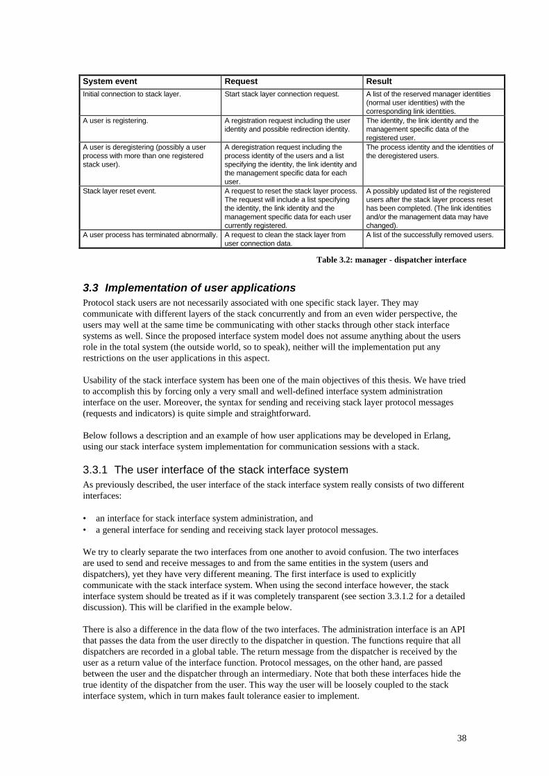
38
System event Request ResultInitial connection to stack layer. Start stack layer connection request. A list of the reserved manager identities
(normal user identities) with thecorresponding link identities.
A user is registering. A registration request including the useridentity and possible redirection identity.
The identity, the link identity and themanagement specific data of theregistered user.
A user is deregistering (possibly a userprocess with more than one registeredstack user).
A deregistration request including theprocess identity of the users and a listspecifying the identity, the link identity andthe management specific data for eachuser.
The process identity and the identities ofthe deregistered users.
Stack layer reset event. A request to reset the stack layer process.The request will include a list specifyingthe identity, the link identity and themanagement specific data for each usercurrently registered.
A possibly updated list of the registeredusers after the stack layer process resethas been completed. (The link identitiesand/or the management data may havechanged).
A user process has terminated abnormally. A request to clean the stack layer fromuser connection data.
A list of the successfully removed users.
Table 3.2: manager - dispatcher interface
3.3 Implementation of user applicationsProtocol stack users are not necessarily associated with one specific stack layer. They maycommunicate with different layers of the stack concurrently and from an even wider perspective, theusers may well at the same time be communicating with other stacks through other stack interfacesystems as well. Since the proposed interface system model does not assume anything about the usersrole in the total system (the outside world, so to speak), neither will the implementation put anyrestrictions on the user applications in this aspect.
Usability of the stack interface system has been one of the main objectives of this thesis. We have triedto accomplish this by forcing only a very small and well-defined interface system administrationinterface on the user. Moreover, the syntax for sending and receiving stack layer protocol messages(requests and indicators) is quite simple and straightforward.
Below follows a description and an example of how user applications may be developed in Erlang,using our stack interface system implementation for communication sessions with a stack.
3.3.1 The user interface of the stack interface systemAs previously described, the user interface of the stack interface system really consists of two differentinterfaces:
• an interface for stack interface system administration, and• a general interface for sending and receiving stack layer protocol messages.
We try to clearly separate the two interfaces from one another to avoid confusion. The two interfacesare used to send and receive messages to and from the same entities in the system (users anddispatchers), yet they have very different meaning. The first interface is used to explicitlycommunicate with the stack interface system. When using the second interface however, the stackinterface system should be treated as if it was completely transparent (see section 3.3.1.2 for a detaileddiscussion). This will be clarified in the example below.
There is also a difference in the data flow of the two interfaces. The administration interface is an APIthat passes the data from the user directly to the dispatcher in question. The functions require that alldispatchers are recorded in a global table. The return message from the dispatcher is received by theuser as a return value of the interface function. Protocol messages, on the other hand, are passedbetween the user and the dispatcher through an intermediary. Note that both these interfaces hide thetrue identity of the dispatcher from the user. This way the user will be loosely coupled to the stackinterface system, which in turn makes fault tolerance easier to implement.
39
The stack interface system runs on a node in a distributed Erlang system (see section 2.8 for a detaileddiscussion). It enables the user processes to be located on other nodes either on the same machine oron other machines on the network. This, in turn, makes it possible to use the stack interface system indistributed network applications, multi-card computers, heterogeneous distributed systems, extendablesystems, etc.
3.3.1.1 The stack interface system administration APIThe administration API includes functions for registration, deregistration and reporting changes ofthe user process identity. There are three different functions for registering a user:
1. for registering without explicitly specifying a user identity,2. for specifying a user identity but no redirection identity, and3. for specifying both a user and a redirection identity.
There are two different functions for deregistering a user (note that it is never necessary to specify aredirection identity when deregistering since the dispatcher will already have that knowledge):
1. for deregistering a user without specifying the user identity (i.e. deregistering all users registeredby the calling process, and
2. for specifying the user identity.
There are two functions for reporting the change of the process identity of the user:
1. for changing the process identity of one specific user, and2. for changing the process identity of all users registered with the old process identity.
3.3.1.2 The stack layer protocol interfaceThe interface for protocol messages is not an API, but a specification of what a request message (tosend to a dispatcher), an indicator message and a return value message (to receive from a dispatcher)should look like. The request message has the general form:
{ReqPrimitive, Parameters},
for sending a request without expecting a return value from the stack layer process. ReqPrimitive isthe request primitive - an atom. Parameters is a list of arguments that should be sent along with therequest. If the user expects a return value from the stack layer process as a result of the request, theninstead the following request form should be used:
{Tag, {ReqPrimitive, Parameters}},
where Tag is an arbitrary value of any type chosen by the user. It will be used to tag the return valuemessage of this particular request so that the user can associate them. When the user sends its requestsit specifies an intermediary as the addressee. (The syntax is not affected if the intermediary is locatedon another Erlang node in the network). The user regards the identity of the intermediary as theaddress of the actual stack layer. Say for example that a user wants to send a so-called ”bind request”to the TCAP layer of an SS7 stack. The user has assigned the process identity of the intermediary tothe variable TCAP. To send the request, the user could execute an expression that looks like this:
TCAP ! {‘TBindReq’, [1, 2]} orTCAP ! {request1, {‘TBindReq’, [1, 2]}},
An indicator message has the general form:
{IndPrimitive, Parameters},
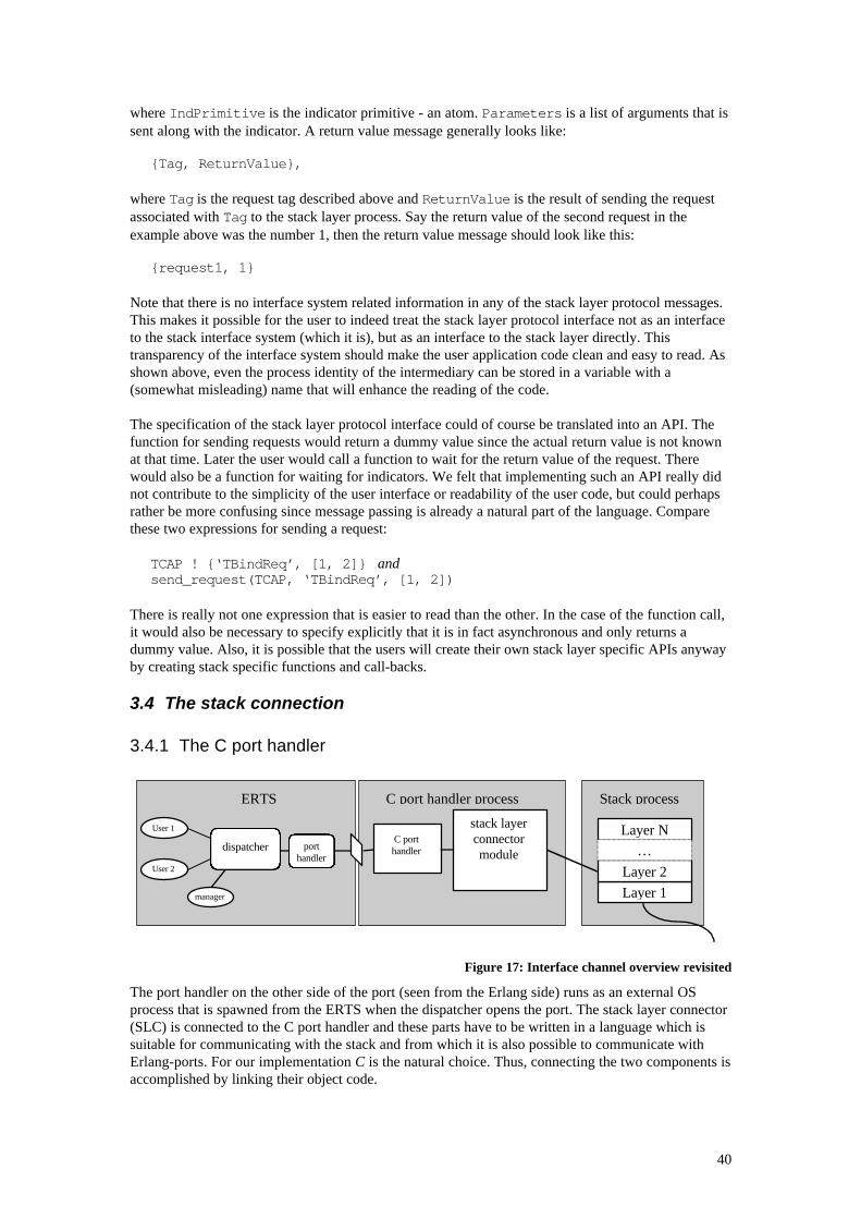
40
where IndPrimitive is the indicator primitive - an atom. Parameters is a list of arguments that issent along with the indicator. A return value message generally looks like:
{Tag, ReturnValue},
where Tag is the request tag described above and ReturnValue is the result of sending the requestassociated with Tag to the stack layer process. Say the return value of the second request in theexample above was the number 1, then the return value message should look like this:
{request1, 1}
Note that there is no interface system related information in any of the stack layer protocol messages.This makes it possible for the user to indeed treat the stack layer protocol interface not as an interfaceto the stack interface system (which it is), but as an interface to the stack layer directly. Thistransparency of the interface system should make the user application code clean and easy to read. Asshown above, even the process identity of the intermediary can be stored in a variable with a(somewhat misleading) name that will enhance the reading of the code.
The specification of the stack layer protocol interface could of course be translated into an API. Thefunction for sending requests would return a dummy value since the actual return value is not knownat that time. Later the user would call a function to wait for the return value of the request. Therewould also be a function for waiting for indicators. We felt that implementing such an API really didnot contribute to the simplicity of the user interface or readability of the user code, but could perhapsrather be more confusing since message passing is already a natural part of the language. Comparethese two expressions for sending a request:
TCAP ! {‘TBindReq’, [1, 2]} andsend_request(TCAP, ‘TBindReq’, [1, 2])
There is really not one expression that is easier to read than the other. In the case of the function call,it would also be necessary to specify explicitly that it is in fact asynchronous and only returns adummy value. Also, it is possible that the users will create their own stack layer specific APIs anywayby creating stack specific functions and call-backs.
3.4 The stack connection
3.4.1 The C port handler
Figure 17: Interface channel overview revisited
The port handler on the other side of the port (seen from the Erlang side) runs as an external OSprocess that is spawned from the ERTS when the dispatcher opens the port. The stack layer connector(SLC) is connected to the C port handler and these parts have to be written in a language which issuitable for communicating with the stack and from which it is also possible to communicate withErlang-ports. For our implementation C is the natural choice. Thus, connecting the two components isaccomplished by linking their object code.
Layer N
Layer 1
Layer 2
…
User 1
User 2
C porthandler
stack layerconnectormodule
ERTS C port handler process Stack process
porthandler
dispatcher
manager
41
The C port handler is used for handling request messages, sent from the dispatcher, by receiving themessages arriving at the port and forwarding them to the stack layer connector.
When the C port handler process is started it calls a function, defined in the stack layer connectormodule, in order to start the stack layer connector. If this succeeds, a message telling that the C porthandler is ready is sent to the dispatcher. The C port handler process is now suspended while waitingfor messages from the dispatcher to arrive at the port.
When a message arrives it is put in a memory buffer and is then decoded into an external Erlang term(usually referred to as an eterm). This eterm can be in one of the following shapes:
1. {LinkId, Request}2. {LinkId, {Tag, Request}}3. <atom>
(LinkId identifies the link on which the issuing user resides. Tag is the tag supplied by the user inorder to identify the return value from the request. Request is the actual request, as defined in3.3.1.2).
The action taken upon receiving an atom (case 3) is to call a function, defined in the stack layerconnector module, that is supposed to close down the stack layer connector, and then to stop the Cport handler process. The action taken upon receiving one of the messages of the first or the secondcase is to hand the elements in the message over to the stack layer connector by using them asarguments when calling a function. The function in question is defined in the stack layer connectormodule that is supposed to execute the request. The difference between the cases 2 and 3 is that incase 2 a return value from the request is required by the user, whereas in case 3 it is not. If the etermcomes in any other shape it is regarded as an error and an error message is issued.
To handle forwarding of indicators and request return values to the dispatcher, the C port handlermodule contains functions that are to be called from the stack layer connector module. Their job is toconstruct indicator messages ({LinkId, Indicator}) and return value messages ({LinkId,{Tag, ReturnValue}}) and send them to the dispatcher. The C port handler module also containsfunctions for checking that the requests and indicators have the correct structure (described in 3.4.2)and functions that build error and empty return values. The interface between the C port handlermodule and the stack layer connector module is called the C port handler interface.
Actually, the C port handler module should not know about the structure of the messages or what theymean. The reason for letting it know anyway is that we want to decide (i.e. we want it to be a part ofthe model) how requests and indicators should be encoded when they are transferred between theusers and the stack layer connector and how they declare whether or not they want to receive a returnvalue from a request. It is actually up to the SLC module designers to decide if they want to use thesechecks, but they are strongly recommended to do so.
The C port handler module uses the Erlang external format both internally (for communication overthe port) and when communicating with the stack layer connector module. If this is not appropriate(e.g. due to performance reasons), another general-data format can be used. It will of course require arewrite of the C port handler module, but the principle of operation will be the same.
3.4.2 The stack layer connector moduleThe stack layer connector is the module that does the actual connection to the stack. The basic idea isto have one stack layer connector (since there is one dispatcher for every layer) for every layer in thestack being used.
A central element in the description of our interface system model is the user. We will here shortlydescribe the concept of a user from the stack layer connector point of view.
42
A user is an entity who communicates with a stack-layer, usually for the purpose of communicatingwith a user of a corresponding layer on another stack, by issuing requests to the stack-layer andreceiving indicators from it. The layer protocol thus contains some kind of knowledge about users (i.e.the two peer layers can 'talk' about users) and users of a layer have to somehow be introduced to thatlayer so that it knows how to send indicators to them. If, for a stack layer, this is not the case there canbe only one user of that layer. The time a user is using a stack layer is here referred to as a usersession.Since the programs that use our interface system to access a stack are also users, we will here call auser that is using a stack-layer directly a layer user, and a user that is registered at the dispatcher aninterface system user.
Another important concept described in the model description is that of a link. A link is a ”physicalpath” for sending requests and indicators between a stack-layer and its users. There can be one linkfor every layer user, but there are also stack layers where there are several layer users per link, inwhich case the indicators contain some kind of data telling which layer user they are destined for.
As described earlier, the purpose of the stack layer connector is to implement a program that - towardsthe stack layer - acts just like a set of normal layer users, but where these users are only simulating theset of interface system users – the real users - and their actions. A message containing a request froman interface system user is sent to a simulated user in the stack layer connector through the C porthandler interface. Also using this interface, a simulated user in the stack layer connector can forwardindicators sent to it from the stack layer to its corresponding interface system user.
Not all stack layers can handle several users, however. In a stack there are often some layers that onlycan have a single user (usually the lower layers), while the other layers support several. Single userlayers are typically easier to write a stack layer connector for since there is no need to administer a setof simulated users or to find out to which one of them indicators are directed. Multi-user layers, on theother hand, are generally a little trickier depending on the manner in which they handle theconnections to their users.
The simulated users in the stack layer connector are thus supposed to do two things:
• Receive indicators sent from the stack layer and forward them through the port handler to theinterface system user that they simulate.
• Receive requests sent from the interface system users and hand them over to the stack layer in thesame shape as if the interface system user had been an ordinary layer user. If desired, the resultfrom the hand-over of the request to the stack layer connector (typically a return value from anAPI function call) should be sent back to the interface system user.
Additionally, in order to be able to simulate the current state of the set of interface system users, thestack layer connector has to have functionality for administering the simulated users. The stack layerconnector is thus not only informed about which requests the interface system users issue, but alsoabout their current states (e.g. if they are registered or deregistered). The messages that contain thiskind of information are exchanged between the manager and the stack layer connector in the samemanner as ordinary requests and indicators. It is the responsibility of the stack layer connector toknow the difference between the described messages above, and ordinary requests and indicators.Supposedly by assigning a link of its own to these messages.
The above-mentioned administration of the simulated users in our interface system we refer to asinterface system management. The stack layer connector may also contain stack managementfunctionality, which is used when performing management on the stack (e.g. starting or stopping thestack). It can be seen as having an interface system user performing management with acorresponding simulated user. They are indeed somewhat special, but fit into the user modelnevertheless.
In order to keep the interface system as general as possible, the stack layer connector is to be writtenby the one who intends to use this interface system, which is the one who has the best knowledge
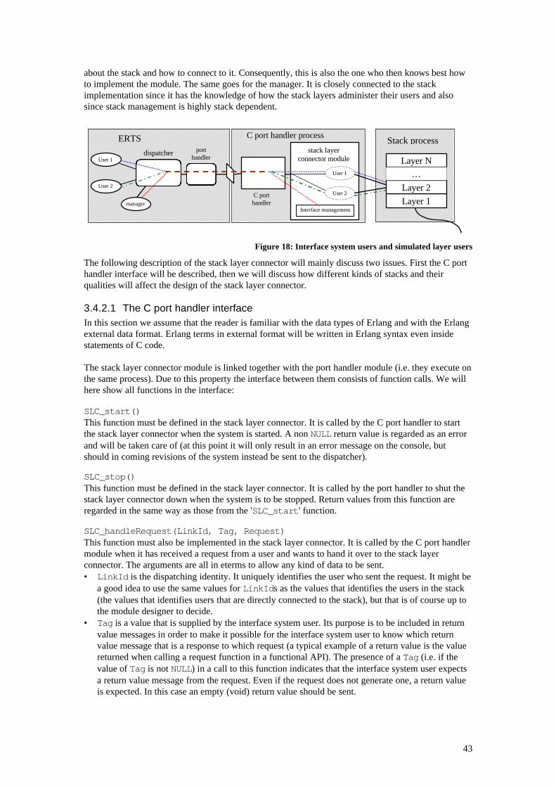
43
about the stack and how to connect to it. Consequently, this is also the one who then knows best howto implement the module. The same goes for the manager. It is closely connected to the stackimplementation since it has the knowledge of how the stack layers administer their users and alsosince stack management is highly stack dependent.
Figure 18: Interface system users and simulated layer users
The following description of the stack layer connector will mainly discuss two issues. First the C porthandler interface will be described, then we will discuss how different kinds of stacks and theirqualities will affect the design of the stack layer connector.
3.4.2.1 The C port handler interfaceIn this section we assume that the reader is familiar with the data types of Erlang and with the Erlangexternal data format. Erlang terms in external format will be written in Erlang syntax even insidestatements of C code.
The stack layer connector module is linked together with the port handler module (i.e. they execute onthe same process). Due to this property the interface between them consists of function calls. We willhere show all functions in the interface:
SLC_start()This function must be defined in the stack layer connector. It is called by the C port handler to startthe stack layer connector when the system is started. A non NULL return value is regarded as an errorand will be taken care of (at this point it will only result in an error message on the console, butshould in coming revisions of the system instead be sent to the dispatcher).
SLC_stop()This function must be defined in the stack layer connector. It is called by the port handler to shut thestack layer connector down when the system is to be stopped. Return values from this function areregarded in the same way as those from the 'SLC_start' function.
SLC_handleRequest(LinkId, Tag, Request)This function must also be implemented in the stack layer connector. It is called by the C port handlermodule when it has received a request from a user and wants to hand it over to the stack layerconnector. The arguments are all in eterms to allow any kind of data to be sent.• LinkId is the dispatching identity. It uniquely identifies the user who sent the request. It might be
a good idea to use the same values for LinkIds as the values that identifies the users in the stack(the values that identifies users that are directly connected to the stack), but that is of course up tothe module designer to decide.
• Tag is a value that is supplied by the interface system user. Its purpose is to be included in returnvalue messages in order to make it possible for the interface system user to know which returnvalue message that is a response to which request (a typical example of a return value is the valuereturned when calling a request function in a functional API). The presence of a Tag (i.e. if thevalue of Tag is not NULL) in a call to this function indicates that the interface system user expectsa return value message from the request. Even if the request does not generate one, a return valueis expected. In this case an empty (void) return value should be sent.
Layer N
Layer 1
Layer 2
…
User 1
User 2
ERTS Stack processport
handlerdispatcher
manager
C porthandler
C port handler process
stack layerconnector module
User 1
User 2
Interface management
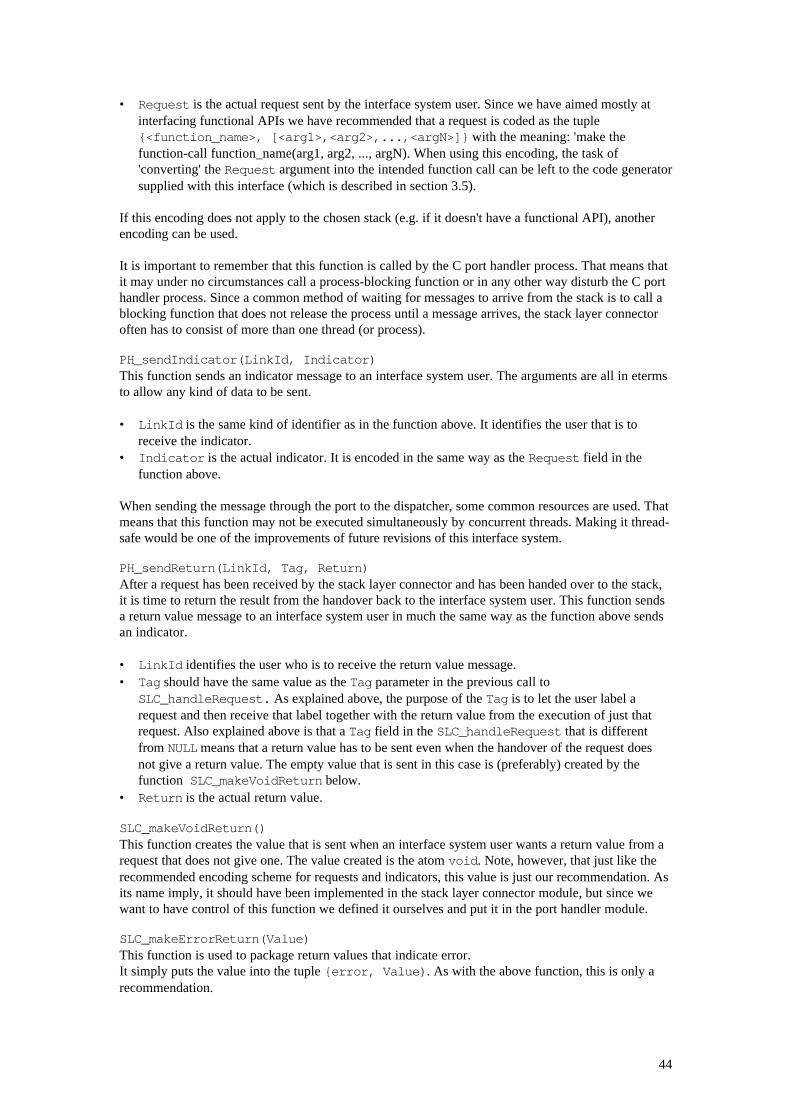
44
• Request is the actual request sent by the interface system user. Since we have aimed mostly atinterfacing functional APIs we have recommended that a request is coded as the tuple{<function_name>, [<arg1>,<arg2>,...,<argN>]} with the meaning: 'make thefunction-call function_name(arg1, arg2, ..., argN). When using this encoding, the task of'converting' the Request argument into the intended function call can be left to the code generatorsupplied with this interface (which is described in section 3.5).
If this encoding does not apply to the chosen stack (e.g. if it doesn't have a functional API), anotherencoding can be used.
It is important to remember that this function is called by the C port handler process. That means thatit may under no circumstances call a process-blocking function or in any other way disturb the C porthandler process. Since a common method of waiting for messages to arrive from the stack is to call ablocking function that does not release the process until a message arrives, the stack layer connectoroften has to consist of more than one thread (or process).
PH_sendIndicator(LinkId, Indicator)This function sends an indicator message to an interface system user. The arguments are all in etermsto allow any kind of data to be sent.
• LinkId is the same kind of identifier as in the function above. It identifies the user that is toreceive the indicator.
• Indicator is the actual indicator. It is encoded in the same way as the Request field in thefunction above.
When sending the message through the port to the dispatcher, some common resources are used. Thatmeans that this function may not be executed simultaneously by concurrent threads. Making it thread-safe would be one of the improvements of future revisions of this interface system.
PH_sendReturn(LinkId, Tag, Return)After a request has been received by the stack layer connector and has been handed over to the stack,it is time to return the result from the handover back to the interface system user. This function sendsa return value message to an interface system user in much the same way as the function above sendsan indicator.
• LinkId identifies the user who is to receive the return value message.• Tag should have the same value as the Tag parameter in the previous call to
SLC_handleRequest. As explained above, the purpose of the Tag is to let the user label arequest and then receive that label together with the return value from the execution of just thatrequest. Also explained above is that a Tag field in the SLC_handleRequest that is differentfrom NULL means that a return value has to be sent even when the handover of the request doesnot give a return value. The empty value that is sent in this case is (preferably) created by thefunction SLC_makeVoidReturn below.
• Return is the actual return value. SLC_makeVoidReturn()This function creates the value that is sent when an interface system user wants a return value from arequest that does not give one. The value created is the atom void. Note, however, that just like therecommended encoding scheme for requests and indicators, this value is just our recommendation. Asits name imply, it should have been implemented in the stack layer connector module, but since wewant to have control of this function we defined it ourselves and put it in the port handler module.
SLC_makeErrorReturn(Value)This function is used to package return values that indicate error.It simply puts the value into the tuple {error, Value). As with the above function, this is only arecommendation.
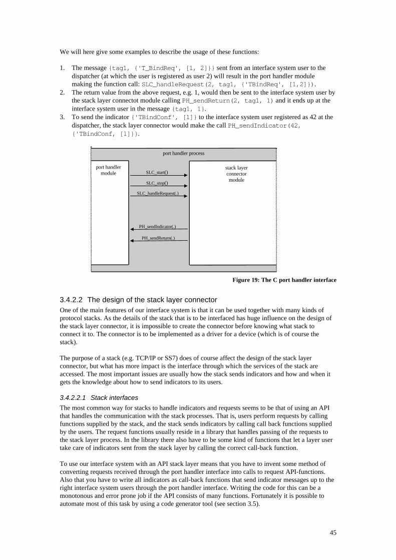
45
We will here give some examples to describe the usage of these functions:
1. The message {tag1, {'T_BindReq', [1, 2]}} sent from an interface system user to thedispatcher (at which the user is registered as user 2) will result in the port handler modulemaking the function call: SLC_handleRequest(2, tag1, {'TBindReq', [1,2]}).
2. The return value from the above request, e.g. 1, would then be sent to the interface system user bythe stack layer connectot module calling PH_sendReturn(2, tag1, 1) and it ends up at theinterface system user in the message {tag1, 1}.
3. To send the indicator {'TBindConf', [1]} to the interface system user registered as 42 at thedispatcher, the stack layer connector would make the call PH_sendIndicator(42,{'TBindConf, [1]}}.
Figure 19: The C port handler interface
3.4.2.2 The design of the stack layer connectorOne of the main features of our interface system is that it can be used together with many kinds ofprotocol stacks. As the details of the stack that is to be interfaced has huge influence on the design ofthe stack layer connector, it is impossible to create the connector before knowing what stack toconnect it to. The connector is to be implemented as a driver for a device (which is of course thestack).
The purpose of a stack (e.g. TCP/IP or SS7) does of course affect the design of the stack layerconnector, but what has more impact is the interface through which the services of the stack areaccessed. The most important issues are usually how the stack sends indicators and how and when itgets the knowledge about how to send indicators to its users.
3.4.2.2.1 Stack interfaces
The most common way for stacks to handle indicators and requests seems to be that of using an APIthat handles the communication with the stack processes. That is, users perform requests by callingfunctions supplied by the stack, and the stack sends indicators by calling call back functions suppliedby the users. The request functions usually reside in a library that handles passing of the requests tothe stack layer process. In the library there also have to be some kind of functions that let a layer usertake care of indicators sent from the stack layer by calling the correct call-back function.
To use our interface system with an API stack layer means that you have to invent some method ofconverting requests received through the port handler interface into calls to request API-functions.Also that you have to write all indicators as call-back functions that send indicator messages up to theright interface system users through the port handler interface. Writing the code for this can be amonotonous and error prone job if the API consists of many functions. Fortunately it is possible toautomate most of this task by using a code generator tool (see section 3.5).
port handlermodule
port handler process
stack layerconnectormodule
SLC_start()
SLC_stop()
SLC_handleRequest(.)
PH_sendIndicator(.)
PH_sendReturn(.)
46
We must not forget about the return values from the function calls. How to handle return values fromrequest functions has been discussed previously, but not return values from indicator functions. Theproblem here is not how to take care of them (which is up to the stack) but rather how to send relevantones. For example, a return value that says “indicator received by user” or “indicator not receivedbecause the user just died a horrible death” is difficult to return since an indicator call back functiondoes not know this kind of facts (it is only known by the dispatcher).
As of yet, our interface system has no special support to deal with this problem. (The latter problemdescribed in the example above could be solved by terminating the simulated layer user as soon as it isdetected that its corresponding interface system user has terminated).
Instead of using an API, communication with a stack should perhaps be performed by reading andwriting directly to a socket, a pipe, a file descriptor or some similar mechanism for connecting theusers to the stack process (see section 1.1.2). We will here call this stream communication. Most stacklayer API's are likely to simply be interfaces built upon stream communication.
The difference between the stack layer connector of an API stack layer and a “stream stack layer” isthat there is no need to 'convert' between messages and function calls in the latter. There will still beneed to convert different types of messages, however. As a result, also the format used to encoderequests and indicators may have to change since the format we have recommended may not be themost suitable when interfacing a stream stack layer.
3.4.2.2.2 Layer users
Our interface system is designed with multi-user stack layers in mind. If only a single user is to beconnected to a stack layer, the features of scalability of the system will not be utilised. Using theinterface system under such circumstances seems to be a bit overkill. While this is not completelyuntrue, the gain of using our interface system should hopefully outweigh the losses anyway. Forstarters, only a little overhead is introduced by the interface system when using it with a single userstack layer. This is because the workload for the dispatcher is proportional to the number of users andbecause the stack layer connector can be made very simple as it no longer has to administer manysimulated layer users.
The advantage of using a thought-through interface system that provides its users with a well-definedenvironment should justify any small additional overhead. If performance is so critical that it is notacceptable anyway, the decision to use a high level language to interface the stack should probably bereconsidered in the first place.
We have designed the internal addressing scheme for our system so that, by using link identities, astack layer connector to a single user stack layer is simply a special case of a stack layer connector to amulti user stack layer (see section 2.3.2.1). We will not go into details on how to connect a single usersince it is when our interface system is used with a multi user stack layer that the most interestingproblems arise and that the generality of our model can really be put to test.
When a stack layer receives a message from its peer and discovers that it is addressed to one of itsusers, it has to know how to send the message to that user. That means that the user must, in one wayor another, already have been introduced to the stack layer. How and when that introduction is done,and what it means, depends on the stack layer. These questions and their influence on the stack layerconnector will be the issue in the following paragraphs.
Messages have to be sent to and from the stack layer process through one or several physical channels.As the users and the stack layer are usually different processes these channels are typically tools forprocess communication. Either the stack layer sends indicators to all its users through only onechannel, or it has a channel for each one of its users. In the first case it must be required that eachindicator message contains an identity saying which user it is destined for. In the latter case there isno need for such an explicit identity. It is indeed possible to encounter a combination of the twostrategies. In such a case it is quite probable that explicit identities are used for all users anyway. If
47
not, there has to be two “levels” of identities to handle and since there can be only one dispatchingidentity in our interface system this would require us to choose one of them or to find a way tocombine them into one (which is a foul solution). In either case it is the task of the stack layerconnector to find out the destination user for all indicator messages and dispatch them to these. A linkin our interface system corresponds to a physical channel.
There are several ways in which a user may have to introduce itself to a stack layer:
• "I am user X". This either means that it is the user of the link X, or that it is user X on the onlylink.
• "I am user X on link Y". Add a new user X at the link Y. If the link does not exist it will have tobe set up.
• "I am user Z on link Y". This means that user Z uses the same link as user X (above) does.• "Which user am I?". The user does not in advance know what identity to use and thus has to ask
the stack layer for one.
The introduction serves to tell the stack layer how to send indicators to the user and can be explicit orimplicit. It can take place at different points in time. Usually it is performed at the beginning of a usersession. But it is also possible that it is performed several times during a session, for examplewhenever a request is handed over to the stack layer. In the former case it may be possible to simplifythe stack layer connector due to the fact that layer users does not necessarily have to hand theirrequests over to the stack layer themselves. That way the simulated users only need to wait forindicators from the stack layer and can leave the responsibility of receiving the requests from theinterface system users and the execution of those to someone else. Since it is far more difficult for asimulated user to wait for messages from two sources that from one, this “cheat” can be of great help.
3.4.2.3 A stack layer connector exampleWe have used our model to create an interface system towards the TCAP-layer of the EricssonInfotech SS7 stack (presented in section 2.7.1). We will here give a description of the system in termsof what have been discussed above.
Communication with the TCAP layer is performed through a functional API, both for requests andindicators. The layer handles multiple users where each user has an identity (ID) that is used in theservice protocol and is included in all requests and indicators. The actual connections (the links) tothe layer are accomplished using sockets. That is, each user can have its own socket to receive itsindicators through, all users can use the same socket, or some users can have their own socketswhereas others have to share theirs. Since there can only be one identity type for dispatching messagesin our interface system there are two possible implementations of the stack layer connector: 1. Let the sockets be the dispatching identity. If every user has its own socket this is the most
straightforward solution. If not, it is the responsibility of the users who share the same socket tomake sure that the indicators end up at the right user, i.e. the users will have to implement theirown dispatcher.
2. Let the IDs be the dispatching identity. If users share sockets, this means that the stack layerconnector has to unpack all indicator messages to get hold of the dispatching identity. Thissolution implies that the stack layer connector has to have knowledge about the contents of theindicator messages and that the automatic code generation might be difficult to use. If, on theother hand, every user has its own socket, then unpacking indicators is not necessary andalternative 1 is better.
It is decided what sockets to use once and for all before the stack is started, whereas which users thatwill use which sockets is decided when the users introduce themselves to the layer by saying ”I amuser X and I use link (socket) Y”.
The main part of the stack layer connector that is to be created for this consists of the functionSLC_handleIndicator(...). It receives the request messages sent from the interface system usersand uses the function created by the code-generator to convert these into function calls. Either into
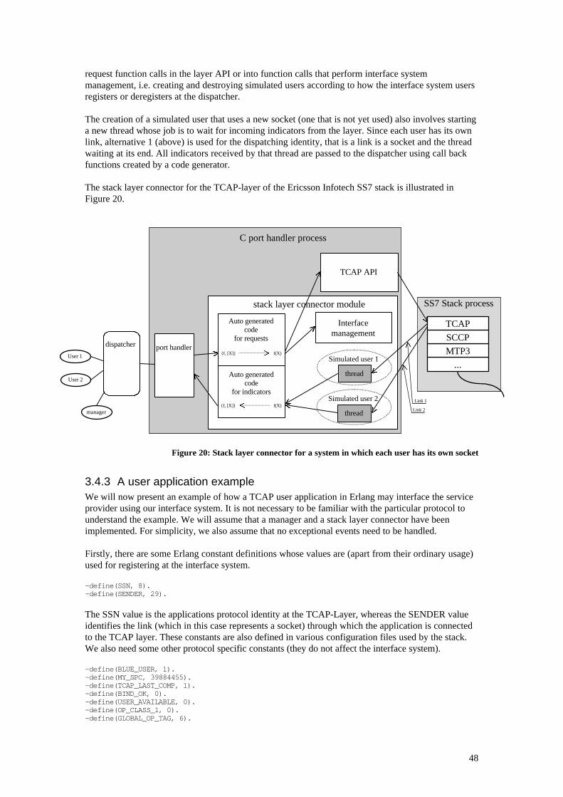
48
request function calls in the layer API or into function calls that perform interface systemmanagement, i.e. creating and destroying simulated users according to how the interface system usersregisters or deregisters at the dispatcher.
The creation of a simulated user that uses a new socket (one that is not yet used) also involves startinga new thread whose job is to wait for incoming indicators from the layer. Since each user has its ownlink, alternative 1 (above) is used for the dispatching identity, that is a link is a socket and the threadwaiting at its end. All indicators received by that thread are passed to the dispatcher using call backfunctions created by a code generator.
The stack layer connector for the TCAP-layer of the Ericsson Infotech SS7 stack is illustrated inFigure 20.
Figure 20: Stack layer connector for a system in which each user has its own socket
3.4.3 A user application exampleWe will now present an example of how a TCAP user application in Erlang may interface the serviceprovider using our interface system. It is not necessary to be familiar with the particular protocol tounderstand the example. We will assume that a manager and a stack layer connector have beenimplemented. For simplicity, we also assume that no exceptional events need to be handled.
Firstly, there are some Erlang constant definitions whose values are (apart from their ordinary usage)used for registering at the interface system.
-define(SSN, 8).-define(SENDER, 29).
The SSN value is the applications protocol identity at the TCAP-Layer, whereas the SENDER valueidentifies the link (which in this case represents a socket) through which the application is connectedto the TCAP layer. These constants are also defined in various configuration files used by the stack.We also need some other protocol specific constants (they do not affect the interface system).
-define(BLUE_USER, 1).-define(MY_SPC, 39884455).-define(TCAP_LAST_COMP, 1).-define(BIND_OK, 0).-define(USER_AVAILABLE, 0).-define(OP_CLASS_1, 0).-define(GLOBAL_OP_TAG, 6).
stack layer connector module
TCAP
...
MTP3
SCCP
SS7 Stack process
TCAP API
Link 1
Link 2
Simulated user 1
thread
Simulated user 2
thread
C port handler process
Interfacemanagement
Auto generatedcode
for requests
Auto generatedcode
for indicators
port handlerdispatcher
User 2
User 1
manager{f, [X]} f(X)
{f, [X]} f(X)
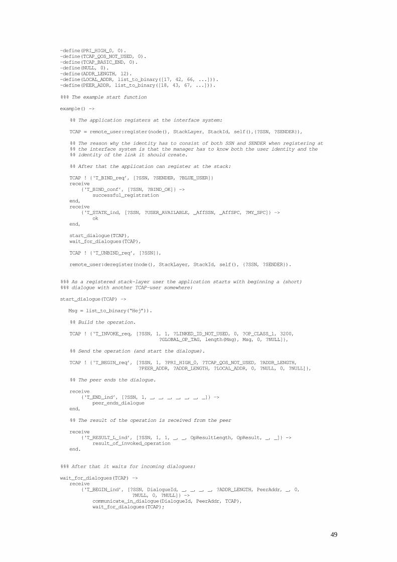
49
-define(PRI_HIGH_0, 0).-define(TCAP_QOS_NOT_USED, 0).-define(TCAP_BASIC_END, 0).-define(NULL, 0).-define(ADDR_LENGTH, 12).-define(LOCAL_ADDR, list_to_binary([17, 42, 66, ...])).-define(PEER_ADDR, list_to_binary([18, 43, 67, ...])).
%%% The example start function
example() ->
%% The application registers at the interface system:
TCAP = remote_user:register(node(), StackLayer, StackId, self(),{?SSN, ?SENDER}),
%% The reason why the identity has to consist of both SSN and SENDER when registering at%% the interface system is that the manager has to know both the user identity and the%% identity of the link it should create.
%% After that the application can register at the stack:
TCAP ! {‘T_BIND_req’, [?SSN, ?SENDER, ?BLUE_USER]}receive {‘T_BIND_conf’, [?SSN, ?BIND_OK]} -> successful_registrationend,receive {‘T_STATE_ind, [?SSN, ?USER_AVAILABLE, _AffSSN, _AffSPC, ?MY_SPC]} -> okend,
start_dialogue(TCAP),wait_for_dialogues(TCAP),
TCAP ! {‘T_UNBIND_req’, [?SSN]},
remote_user:deregister(node(), StackLayer, StackId, self(), {?SSN, ?SENDER}).
%%% As a registered stack-layer user the application starts with beginning a (short)%%% dialogue with another TCAP-user somewhere:
start_dialogue(TCAP) ->
Msg = list_to_binary(“Hej”)).
%% Build the operation.
TCAP ! {‘T_INVOKE_req, [?SSN, 1, 1, ?LINKED_ID_NOT_USED, 0, ?OP_CLASS_1, 3200, ?GLOBAL_OP_TAG, length(Msg), Msg, 0, ?NULL]},
%% Send the operation (and start the dialogue).
TCAP ! {‘T_BEGIN_req’, [?SSN, 1, ?PRI_HIGH_0, ?TCAP_QOS_NOT_USED, ?ADDR_LENGTH, ?PEER_ADDR, ?ADDR_LENGTH, ?LOCAL_ADDR, 0, ?NULL, 0, ?NULL]},
%% The peer ends the dialogue.
receive {‘T_END_ind’, [?SSN, 1, _, _, _, _, _, _, _]} -> peer_ends_dialogueend,
%% The result of the operation is received from the peer
receive {‘T_RESULT_L_ind’, [?SSN, 1, 1, _, _, OpResultLength, OpResult, _, _]} -> result_of_invoked_operationend.
%%% After that it waits for incoming dialogues:
wait_for_dialogues(TCAP) ->receive {‘T_BEGIN_ind’, [?SSN, DialogueId, _, _, _, _, ?ADDR_LENGTH, PeerAddr, _, 0,
?NULL, 0, ?NULL]} -> communicate_in_dialogue(DialogueId, PeerAddr, TCAP), wait_for_dialogues(TCAP);
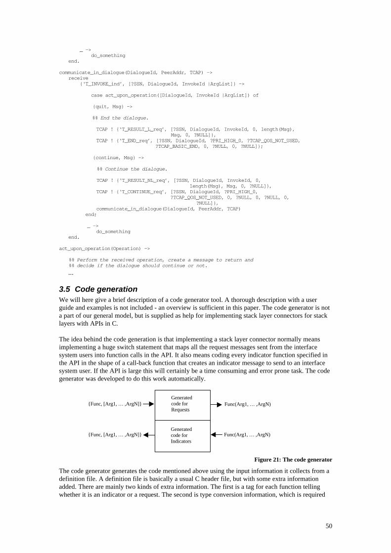
50
_ -> do_somethingend.
communicate_in_dialogue(DialogueId, PeerAddr, TCAP) ->receive {‘T_INVOKE_ind’, [?SSN, DialogueId, InvokeId |ArgList]} ->
case act_upon_operation([DialogueId, InvokeId |ArgList]) of
{quit, Msg} ->
%% End the dialogue.
TCAP ! {‘T_RESULT_L_req’, [?SSN, DialogueId, InvokeId, 0, length(Msg),Msg, 0, ?NULL]},
TCAP ! {‘T_END_req’, [?SSN, DialogueId, ?PRI_HIGH_0, ?TCAP_QOS_NOT_USED, ?TCAP_BASIC_END, 0, ?NULL, 0, ?NULL]};
{continue, Msg} ->
%% Continue the dialogue.
TCAP ! {‘T_RESULT_NL_req’, [?SSN, DialogueId, InvokeId, 0,length(Msg), Msg, 0, ?NULL]},
TCAP ! {‘T_CONTINUE_req’, [?SSN, DialogueId, ?PRI_HIGH_0, ?TCAP_QOS_NOT_USED, 0, ?NULL, 0, ?NULL, 0,
?NULL]}, communicate_in_dialogue(DialogueId, PeerAddr, TCAP)
end;
_ -> do_somethingend.
act_upon_operation(Operation) ->
%% Perform the received operation, create a message to return and%% decide if the dialogue should continue or not.
...
3.5 Code generationWe will here give a brief description of a code generator tool. A thorough description with a userguide and examples is not included - an overview is sufficient in this paper. The code generator is nota part of our general model, but is supplied as help for implementing stack layer connectors for stacklayers with APIs in C.
The idea behind the code generation is that implementing a stack layer connector normally meansimplementing a huge switch statement that maps all the request messages sent from the interfacesystem users into function calls in the API. It also means coding every indicator function specified inthe API in the shape of a call-back function that creates an indicator message to send to an interfacesystem user. If the API is large this will certainly be a time consuming and error prone task. The codegenerator was developed to do this work automatically.
Figure 21: The code generator
The code generator generates the code mentioned above using the input information it collects from adefinition file. A definition file is basically a usual C header file, but with some extra informationadded. There are mainly two kinds of extra information. The first is a tag for each function tellingwhether it is an indicator or a request. The second is type conversion information, which is required
Generatedcode forRequests
Generatedcode forIndicators
{Func, [Arg1, … ,ArgN]}
{Func, [Arg1, … ,ArgN]}
Func(Arg1, … ,ArgN)
Func(Arg1, … ,ArgN)
51
since the generated code shall also be able to convert data between normal C data types and the Erlangexternal format. It is represented as a table stating which Erlang data-type corresponds to which Cdata-type being used.
Given a definitions file, the generator will create a function that takes the term {FunctionName,[Arg1, Arg2, ..., ArgN]} (in the Erlang external format) and calls the API request function'FunctionName(Arg1, Arg2, ..., ArgN)' (if it was specified in the definitions file). Thefunction returns the value returned from the API request call (also in external format).
It also generates code for each indicator call-back function in the API. Such a function sends themessage {<indicator name>, [<function arg1>, <arg2>, ..., <argN>]} to aninterface system user.
3.6 Methods for crash recoveryNo mechanisms for system crash recovery have been implemented in the prototype as of now exceptfor the handling of users that terminate. The implementation of the stack interface system follows theproposed model in which a well-defined control structure has been described. This control structure(i.e. supervision, process links, etc.) provides the base for all kinds of local crash recovery solutions.(By local crash recovery we mean fault tolerance in one stack interface system that runs on onemachine). The prototype is consequently open, and in some cases also prepared, for local recoveryoperations. See the detailed discussion in section 2.4 for more information.
An example of a local crash is if the manager process terminates unexpectedly due to a software error.A possible recovery scenario: The supervisor and the dispatchers will detect the crash and thesupervisor will attempt to restart the manager. If the restart succeeds the dispatchers will be notifiedso that they may update their states and resume traffic. The manager will itself be responsible fordoing possible data recovery during restart.
As implied above, crash recovery for a stack interface system may have to be implemented on differentlevels. Having a local control strategy together with persistent dispatching (and possibly management)data, which would serve as a base for local recovery operations, may not be sufficient. Consider adistributed system in which the computer that hosts the stack interface system crashes. For manyapplications, especially in the world of telecommunication, this is an event that the system has torecover from without data loss or major delays. Examples of required mechanisms for recovery on thislevel are data redundancy, distributed subsystem supervision and control as well as a high-level errordetection (and/or correction) communication protocol. A robust and fault tolerant stack interfacesystem should really be prepared for recovery operations on any level so that it may be configured torun in any environment.
We have throughout the work on this thesis tried to focus on the general use of a stack interface.When it comes to crash recovery, it is quite hard to come up with a design and implementation thatcan meet any general requirements. Of course it is possible to implement fault tolerance on differentlevels, as mentioned above, but what if the system should be integrated with some other application,as discussed in 2.8? What should then e.g. the system recovery API look like? The solution is rather tohave these applications, together with the stack interface system component, comply with somegeneral model for how to develop distributed, fault tolerant software. As described in 1.2.6, OTP is amodel for this, especially suitable for Erlang applications. We will therefore discuss some generalOTP mechanisms to point out interesting aspects of how our interface system is and can beimplemented to comply with a higher order control system.
3.6.1 Making an OTP compliant stack interface systemA software system based on OTP consists of one or more applications. Each application has a controlstructure in the form of a supervision tree, implemented as a hierarchy of supervisor processes. Eachsupervisor is created using a generic pattern (a so-called supervisor behaviour) and will in runtime beresponsible for the supervision of one or more child processes. A child process can be a so-called
52
worker process or another supervisor. (Not surprisingly it is the worker processes that actually “do thejob”, while as the supervisors only implement the control strategies).
The processes executing in an OTP application may well be distributed on different nodes (Erlangruntime systems) as well as on different machines in a network. (The processes may also execute codewritten in other languages than Erlang, running on top of the OS and communicating with thesupervisors through ports). It is the configuration of the supervisors that determine the crash recoveryscheme. A supervisor can for example be configured to attempt restart of some worker processes on alocal node if they should terminate abnormally. If it fails to restart the processes it could terminate andleave it up to the supervisor on the level above to try to start this part of the system up on anothernode. If this supervisor also fails (or can not execute at all because the local machine has gone down)the supervisor on the next level above may try to start the subsystem up on a node on a differentmachine in the network. This is what we mean by “distributed subsystem supervision and control” inthe section above.
The supervisor in our stack interface system could quite easily be fitted into an OTP supervision tree.This supervisor would be configured to do supervision and crash recovery locally where the otherprocesses in the stack interface system would be the worker processes. As in the example above, asupervisor on a higher level could take care of more serious crashes by taking advantage of thedistributed environment (if there is one). Note that this system would (or could) still use the basiccontrol structure of the interface system components that has been proposed in this thesis.
As mentioned above, another mechanism needed to perform crash recovery is data redundancy andpersistence. This could also quite easily be implemented in the stack interface system of today. Thedistributed real-time database Mnesia [20], integrated in OTP, offers persistent storage, datareplication and atomic transactions. Processes in the stack interface system that carry important data,like dispatching tables and process states, could use Mnesia to save this information. Mnesia wouldreplicate the data on other nodes, possibly standby-nodes, in the network. If the stack layer connectorneeds to be able to recover its state after a crash, it could also use Mnesia continuously for storing itsdata. It could access Mnesia indirectly through the manager (on the Erlang side of the port) or use aMnesia Corba/IDL interface for direct access. What could be an issue when using Mnesia for interfacesystem data replication (or any other database solution, for that matter), is efficiency. The tables forthe dispatchers need to be replicated continuously, but perhaps the state of each stack layer channel(i.e. the state of each process in the channel) should only be stored every once in a while when thechannel is in a recognised stable state. (Mnesia offers a so-called checkpoint operation for suchpurposes).
3.7 Flaws, restrictions and improvementsThe stack interface system prototype has quite a few flaws and restrictions. Most of the problems thatwe know of, we have already pointed out in the sections describing the different components and inthe section dealing with crash recovery above. We may proudly certify that there are no apparentfaults in the implementation that actually result from problems with the interface system model itself.There is always room for improvement, especially when it comes to issues of efficiency. We will heregive a few examples of implemented parts that have - or may have - something left to wish for.
We have decided to have exactly one Erlang-C port assigned to each stack layer channel. The mainmotivation is that it makes the port handling easier on both the Erlang and the C side of the systemcompared to having a scaleable port handling functionality. We also believe that we will not gainmuch speed using a scaleable port solution even during sessions with heavy traffic since the portcommunication overhead itself is quite expensive (especially the OS context switch), see section 2.9for more information. It is very likely to believe that the port will be a major bottleneck in our systemduring sessions of heavy traffic. A way to overcome this problem, or to at least make it less critical,would be to reduce the number of OS context switches during these sessions. This could perhaps beaccomplished by allowing for tailoring of the sizes of the port-buffers or of the size of the messages bypacking many small messages into one before sending the data over the port. The overhead of doingthe packing/unpacking should hopefully only take a fraction of the time of an OS context switch.
53
Another, more risky, approach is of course to (as also described in 2.9) use a linked-in driver for theport communication.
If any, or both, of these solutions should turn out to be efficient enough, then it is quite possible thatwe will find another bottleneck in the stack layer channel - the dispatcher. All traffic goes through thedispatcher and for a user request, the dispatcher will lookup a stack layer link identity in a table and,for an indicator or return value, the user PID. It might turn out that these lookup times are critical tothe overall performance of the system during heavy load. In the prototype today, there is one hashtable used for both the mapping from stack layer link identities to the user PIDs as well the other wayaround. Consequently, the lookup operation will only be truly efficient for either the requests or theindicators and return values, depending on what type of data is used as the key. (In the currentimplementation the link identity is used as the key). For more efficient lookup operations, thedispatcher should maintain two hash tables, one for each type of key. This will of course also raisequestions regarding trade-off between memory usage and performance.
The overhead introduced by the intermediary processes could be removed by supplying an additionalfunction for users registering at the interface system that differs from the existing functions in that itexplicitly creates a link between the user process and the dispatcher (e.gremote_user:register_link(...)).
If the dispatcher would still be the one true bottleneck in the stack layer channel even after optimisingaccess of dispatching information, then perhaps a scaleable implementation making load sharing overmultiple dispatchers per channel should be considered. If the system will have to run with a heavyload on more than one stack layer channel, then perhaps the host machine itself will turn out to be themajor bottleneck, not the dispatchers. Making traffic load sharing possible by running differentinterface channels (or different parts of the channels) on different host machines is possible, but couldbe very hard to implement efficiently.
The port handler is currently a process that receives all messages sent from the dispatcher. This makesit impossible to create a single stack layer connector process that can receive messages from both thedispatcher and the stack at the same time. In order to allow this construction we can reduce the porthandler into a function library. This would mean that the process that receives messages from thedispatcher would have to be created in the stack layer connector and that the port handler wouldcontain only the knowledge about the protocol used over the port.
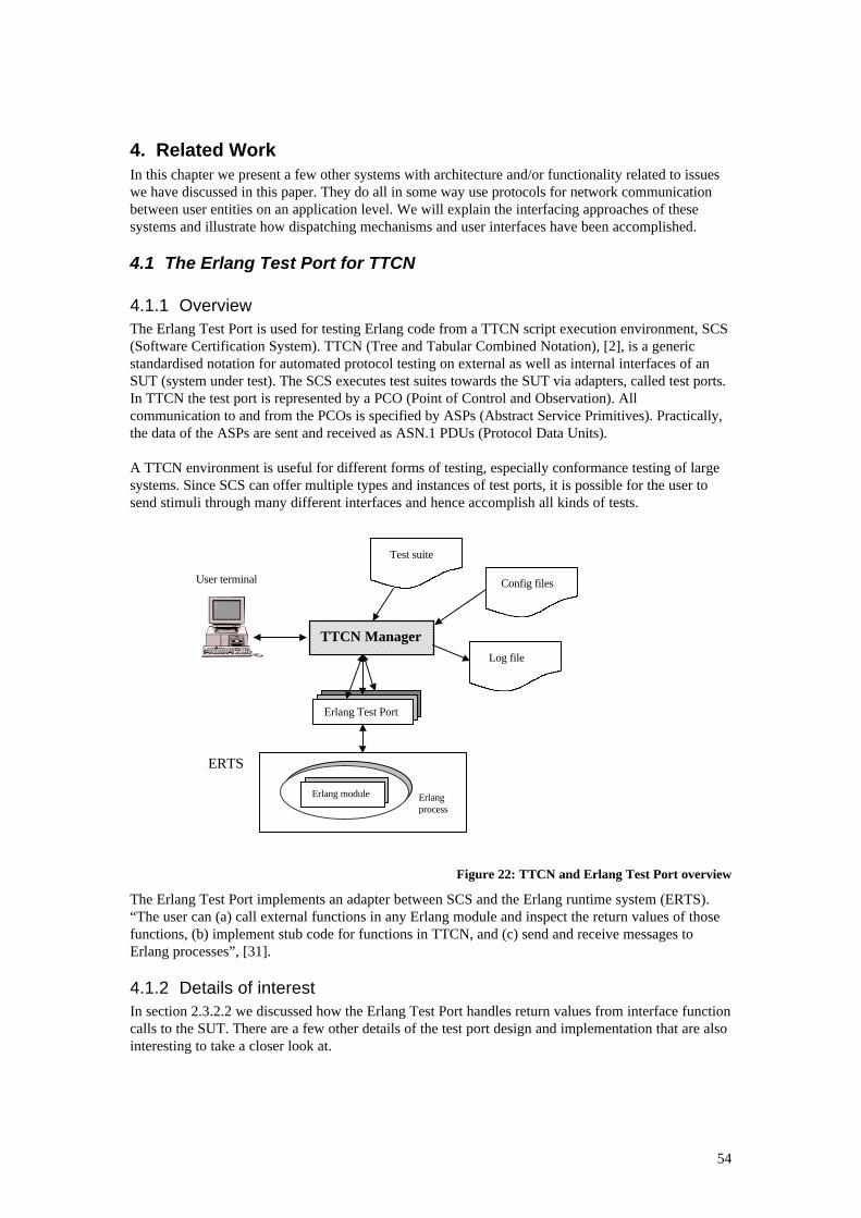
54
4. Related WorkIn this chapter we present a few other systems with architecture and/or functionality related to issueswe have discussed in this paper. They do all in some way use protocols for network communicationbetween user entities on an application level. We will explain the interfacing approaches of thesesystems and illustrate how dispatching mechanisms and user interfaces have been accomplished.
4.1 The Erlang Test Port for TTCN
4.1.1 OverviewThe Erlang Test Port is used for testing Erlang code from a TTCN script execution environment, SCS(Software Certification System). TTCN (Tree and Tabular Combined Notation), [2], is a genericstandardised notation for automated protocol testing on external as well as internal interfaces of anSUT (system under test). The SCS executes test suites towards the SUT via adapters, called test ports.In TTCN the test port is represented by a PCO (Point of Control and Observation). Allcommunication to and from the PCOs is specified by ASPs (Abstract Service Primitives). Practically,the data of the ASPs are sent and received as ASN.1 PDUs (Protocol Data Units).
A TTCN environment is useful for different forms of testing, especially conformance testing of largesystems. Since SCS can offer multiple types and instances of test ports, it is possible for the user tosend stimuli through many different interfaces and hence accomplish all kinds of tests.
Figure 22: TTCN and Erlang Test Port overview
The Erlang Test Port implements an adapter between SCS and the Erlang runtime system (ERTS).“The user can (a) call external functions in any Erlang module and inspect the return values of thosefunctions, (b) implement stub code for functions in TTCN, and (c) send and receive messages toErlang processes”, [31].
4.1.2 Details of interestIn section 2.3.2.2 we discussed how the Erlang Test Port handles return values from interface functioncalls to the SUT. There are a few other details of the test port design and implementation that are alsointeresting to take a closer look at.
TTCN Manager
Erlang Test Port
Test suite
Config files
Log file
Erlangprocess
Erlang module
ERTS
User terminal
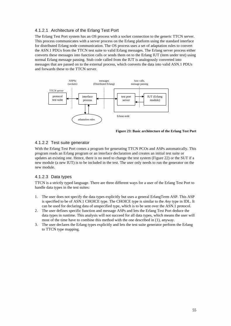
55
4.1.2.1 Architecture of the Erlang Test PortThe Erlang Test Port system has an OS process with a socket connection to the generic TTCN server.This process communicates with a server process on the Erlang platform using the standard interfacefor distributed Erlang node communication. The OS process uses a set of adaptation rules to convertthe ASN.1 PDUs from the TTCN test suite to valid Erlang messages. The Erlang server process eitherconverts these messages into function calls or sends them on to the Erlang IUT (item under test) usingnormal Erlang message passing. Stub code called from the IUT is analogously converted intomessages that are passed on to the external process, which converts the data into valid ASN.1 PDUsand forwards these to the TTCN server.
Figure 23: Basic architecture of the Erlang Test Port
4.1.2.2 Test suite generatorWith the Erlang Test Port comes a program for generating TTCN PCOs and ASPs automatically. Thisprogram reads an Erlang program or an interface declaration and creates an initial test suite orupdates an existing one. Hence, there is no need to change the test system (Figure 22) or the SUT if anew module (a new IUT) is to be included in the test. The user only needs to run the generator on thenew module.
4.1.2.3 Data typesTTCN is a strictly typed language. There are three different ways for a user of the Erlang Test Port tohandle data types in the test suites:
1. The user does not specify the data types explicitly but uses a general ErlangTerm ASP. This ASPis specified to be of ASN.1 CHOICE type. The CHOICE type is similar to the Any type in IDL. Itcan be used for declaring data of unspecified type, which is to be sent over the ASN.1 protocol.
2. The user defines specific function and message ASPs and lets the Erlang Test Port deduce thedata types in runtime. This analysis will not succeed for all data types, which means the user willmost of the time have to combine this method with the one described in (1), anyway.
3. The user declares the Erlang types explicitly and lets the test suite generator perform the Erlangto TTCN type mapping.
func calls,message passing
messages(Distributed Erlang)
ASPSs(sockets)
TTCN server
protocoltest suite
interfaceprocess
adaptation rulesErlang node
IUT (Erlangmodule)
test portserver
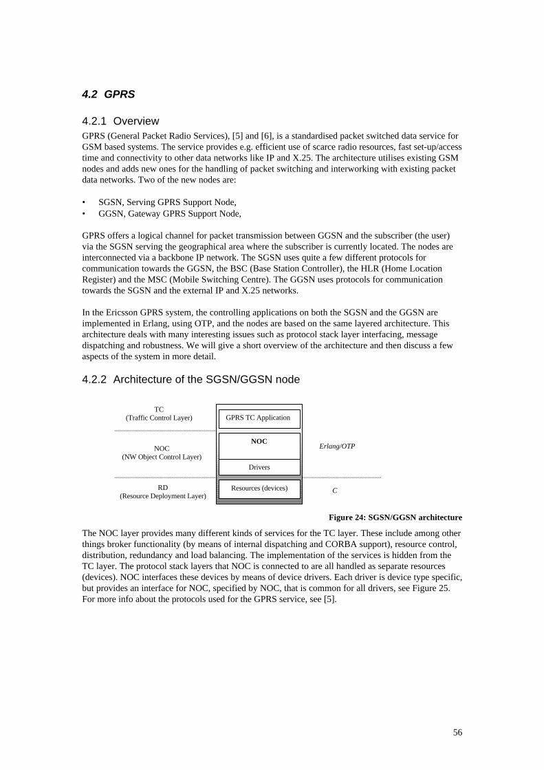
56
4.2 GPRS
4.2.1 OverviewGPRS (General Packet Radio Services), [5] and [6], is a standardised packet switched data service forGSM based systems. The service provides e.g. efficient use of scarce radio resources, fast set-up/accesstime and connectivity to other data networks like IP and X.25. The architecture utilises existing GSMnodes and adds new ones for the handling of packet switching and interworking with existing packetdata networks. Two of the new nodes are:
• SGSN, Serving GPRS Support Node,• GGSN, Gateway GPRS Support Node,
GPRS offers a logical channel for packet transmission between GGSN and the subscriber (the user)via the SGSN serving the geographical area where the subscriber is currently located. The nodes areinterconnected via a backbone IP network. The SGSN uses quite a few different protocols forcommunication towards the GGSN, the BSC (Base Station Controller), the HLR (Home LocationRegister) and the MSC (Mobile Switching Centre). The GGSN uses protocols for communicationtowards the SGSN and the external IP and X.25 networks.
In the Ericsson GPRS system, the controlling applications on both the SGSN and the GGSN areimplemented in Erlang, using OTP, and the nodes are based on the same layered architecture. Thisarchitecture deals with many interesting issues such as protocol stack layer interfacing, messagedispatching and robustness. We will give a short overview of the architecture and then discuss a fewaspects of the system in more detail.
4.2.2 Architecture of the SGSN/GGSN node
Figure 24: SGSN/GGSN architecture
The NOC layer provides many different kinds of services for the TC layer. These include among otherthings broker functionality (by means of internal dispatching and CORBA support), resource control,distribution, redundancy and load balancing. The implementation of the services is hidden from theTC layer. The protocol stack layers that NOC is connected to are all handled as separate resources(devices). NOC interfaces these devices by means of device drivers. Each driver is device type specific,but provides an interface for NOC, specified by NOC, that is common for all drivers, see Figure 25.For more info about the protocols used for the GPRS service, see [5].
GPRS TC Application
NOC
Drivers
Resources (devices)
TC(Traffic Control Layer)
NOC(NW Object Control Layer)
RD(Resource Deployment Layer)
Erlang/OTP
C
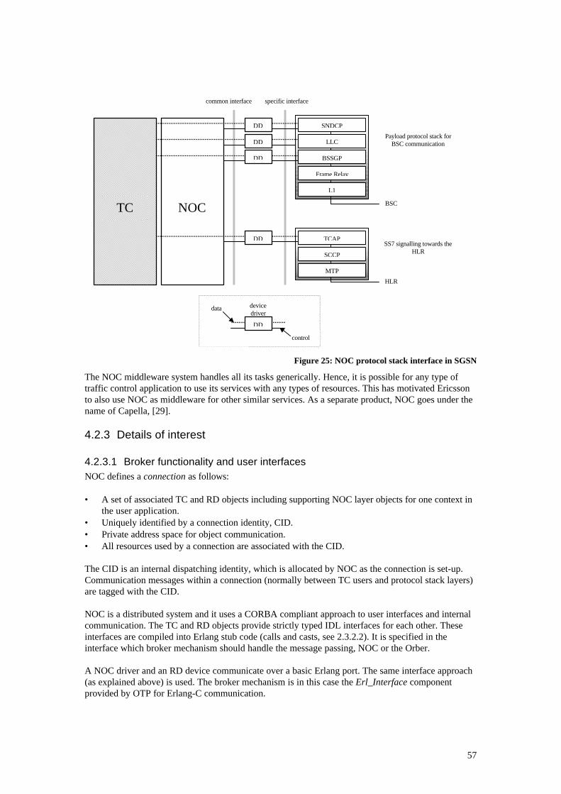
57
Figure 25: NOC protocol stack interface in SGSN
The NOC middleware system handles all its tasks generically. Hence, it is possible for any type oftraffic control application to use its services with any types of resources. This has motivated Ericssonto also use NOC as middleware for other similar services. As a separate product, NOC goes under thename of Capella, [29].
4.2.3 Details of interest
4.2.3.1 Broker functionality and user interfacesNOC defines a connection as follows:
• A set of associated TC and RD objects including supporting NOC layer objects for one context inthe user application.
• Uniquely identified by a connection identity, CID.• Private address space for object communication.• All resources used by a connection are associated with the CID.
The CID is an internal dispatching identity, which is allocated by NOC as the connection is set-up.Communication messages within a connection (normally between TC users and protocol stack layers)are tagged with the CID.
NOC is a distributed system and it uses a CORBA compliant approach to user interfaces and internalcommunication. The TC and RD objects provide strictly typed IDL interfaces for each other. Theseinterfaces are compiled into Erlang stub code (calls and casts, see 2.3.2.2). It is specified in theinterface which broker mechanism should handle the message passing, NOC or the Orber.
A NOC driver and an RD device communicate over a basic Erlang port. The same interface approach(as explained above) is used. The broker mechanism is in this case the Erl_Interface componentprovided by OTP for Erlang-C communication.
common interface
NOC
Payload protocol stack forBSC communication
BSC
SNDCP
LLC
BSSGP
Frame Relay
L1
HLR
TCAP
SCCP
MTP
SS7 signalling towards theHLR
TC
DD
DD
DD
DD
devicedriver
control
data
DD
specific interface
58
4.2.3.2 Recovery and redundancyEricsson GPRS uses the OTP runtime control structure as the underlying mechanism for robustnessand reliability. NOC defines the recovery and redundancy strategies for the complete distributed userapplication. It implements an abstraction on top of OTP to provide this functionality. Here areexamples of some of the features:
• N+M redundancy (a set of computing boards are pointed out as standby for active ones).• Data is replicated on standby boards.• Several restart levels are defined to recover from different types of failures, depending on impact
and severity.
4.3 CORBA
4.3.1 OverviewThe standardisation organisation OMG (Object Management Group) has created a standard called theObject Management Architecture (OMA), which defines various facilities for distributed objectoriented computing. The core of the OMA is the Object Request Broker (ORB), a mechanism thatprovides transparency of object location, activation and communication, [12]. OMG has alsopublished a concrete specification based on OMA, called the Common Object Request BrokerArchitecture (CORBA). The major components of CORBA are:
• The ORB• Interface Definition Language (IDL)• Dynamic Invocation Interface (DII)• Interface Repository (IR)• Object Adapter (OA)
One important aim of CORBA is to make it possible to communicate encapsulated objects betweenprocesses in a distributed environment. Furthermore, the programming interface should not only besystem- but also language-independent.
4.3.1.1 The ORBThe purpose of the ORB is to deliver requests to server objects and return any output values back tothe clients. The implementation of this middleman behaviour is completely transparent to the clientand so is the location of the server object. The client addresses the server using a server objectreference. This is the identity of the server object, which allows the ORB to locate and forwardrequests to it. A client can issue requests by means of two different types of invocations:
• static, via client stubs, and• dynamic, via the DII (see below).
The ORB is language-specific. Different vendors, typically members of the OMG, develop CORBAcompliant ORBs (and IDL compilers, see below) for different languages and platforms.
4.3.1.2 IDLIDL is an OO description language used in CORBA to specify the services provided by a server object.The interface is actually a data type in itself, which is used as the object reference by the ORB. Thelanguage is strictly typed and has a syntax that very much resembles C++. The IDL interfaces may becompiled into client stub- and/or server skeleton-code for static invocations of the particular ORB.
4.3.1.3 DII, IR and OAThe DII is a generic client-side stub capable of forwarding any request to any object. It is quiteinefficient to use compared to performing static invocations. The primary function of the IR is toprovide the type information necessary to issue requests using the DII, [12].
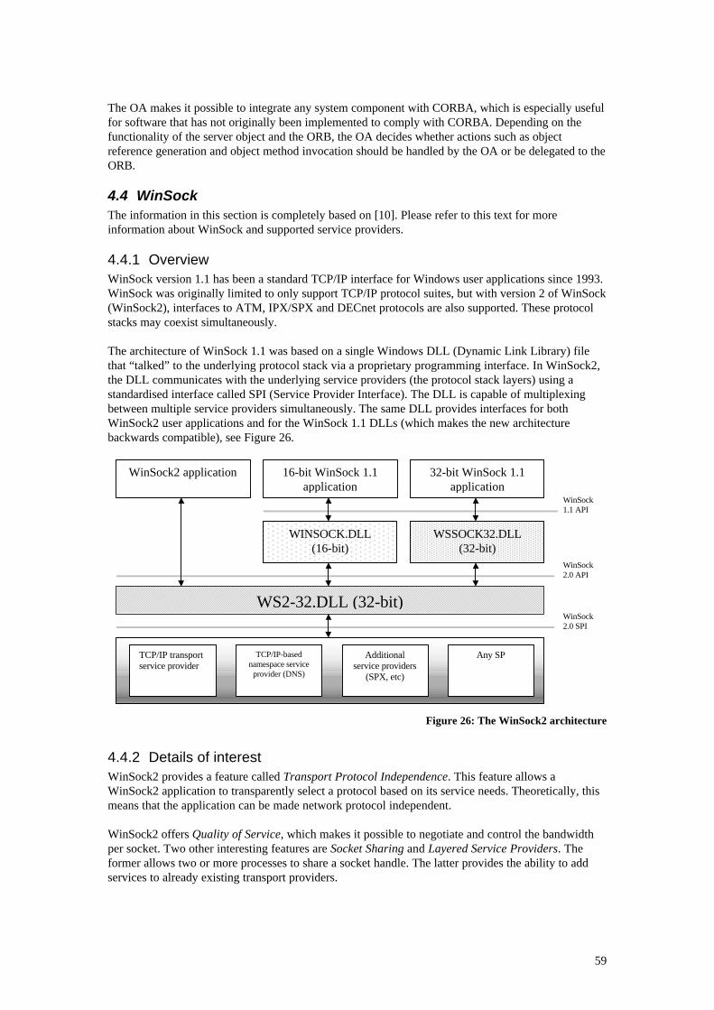
59
The OA makes it possible to integrate any system component with CORBA, which is especially usefulfor software that has not originally been implemented to comply with CORBA. Depending on thefunctionality of the server object and the ORB, the OA decides whether actions such as objectreference generation and object method invocation should be handled by the OA or be delegated to theORB.
4.4 WinSockThe information in this section is completely based on [10]. Please refer to this text for moreinformation about WinSock and supported service providers.
4.4.1 OverviewWinSock version 1.1 has been a standard TCP/IP interface for Windows user applications since 1993.WinSock was originally limited to only support TCP/IP protocol suites, but with version 2 of WinSock(WinSock2), interfaces to ATM, IPX/SPX and DECnet protocols are also supported. These protocolstacks may coexist simultaneously.
The architecture of WinSock 1.1 was based on a single Windows DLL (Dynamic Link Library) filethat “talked” to the underlying protocol stack via a proprietary programming interface. In WinSock2,the DLL communicates with the underlying service providers (the protocol stack layers) using astandardised interface called SPI (Service Provider Interface). The DLL is capable of multiplexingbetween multiple service providers simultaneously. The same DLL provides interfaces for bothWinSock2 user applications and for the WinSock 1.1 DLLs (which makes the new architecturebackwards compatible), see Figure 26.
Figure 26: The WinSock2 architecture
4.4.2 Details of interestWinSock2 provides a feature called Transport Protocol Independence. This feature allows aWinSock2 application to transparently select a protocol based on its service needs. Theoretically, thismeans that the application can be made network protocol independent.
WinSock2 offers Quality of Service, which makes it possible to negotiate and control the bandwidthper socket. Two other interesting features are Socket Sharing and Layered Service Providers. Theformer allows two or more processes to share a socket handle. The latter provides the ability to addservices to already existing transport providers.
WinSock1.1 API
WS2-32.DLL (32-bit)
WinSock2 application 16-bit WinSock 1.1application
32-bit WinSock 1.1application
WINSOCK.DLL(16-bit)
WSSOCK32.DLL(32-bit)
TCP/IP transportservice provider
TCP/IP-basednamespace service
provider (DNS)
Additionalservice providers
(SPX, etc)
Any SP
WinSock2.0 API
WinSock2.0 SPI

60
The main protocol specification of WinSock2 is protocol-independent. However, it also includes anumber of protocol-specific extensions.
AcknowledgementsWe would like to thank the following persons who have contributed with their time, knowledge andexperience to help us complete this thesis:
Gunilla Hugosson at Erlang Systems, for being an excellent mentor and supervisor.
Claes Wikström at the Ericsson CS Laboratory, for sharing his knowledge of the “tricky parts” of theErlang system with us.
Erik Johansson at the University of Uppsala, for helping us find interesting reference documents (andfor waiting so patiently for us to finish this paper).
The engineers at ICCC in Copenhagen, for providing us with invaluable information about e.g.general requirements of industrial telecommunication applications.
The persons in the Intelligent Network project at LMD (Ericsson Denmark) in Copenhagen, forgiving lots of useful input to our work and for having enough confidence in us to incorporate ourinterface system prototype in their commercial system.
Roy Bengtsson and Henrik Forsgren at Erlang Systems, for making it possible for us to have animportant meeting and workshop at LMD in Copenhagen.
Martin Creathorn, also at Erlang Systems, for continuously finding experienced engineers withinEricsson for us to talk to and learn from.
Everyone else at Erlang Systems - there was always someone there to willingly and patiently help usout with any question or problem we might have.
61
References[1] The Common Object Request Broker: Architecture and Specification, OMG TC 91.12.1, Rev.
1.1, 1991
[2] Tree and Tabular Combined Notation, ISO/IEC 9646-3, 1991
[3] Open systems interconnection – Basic reference model: The basic model, ISO/IEC 7498-1,
1994
[4] Transmission Control Protocol, RFC 793, September 1981
[5] General Packet Radio Service (GPRS); Service Description, GSM 03.60 v6.4.0, 1997
[6] Network architecture, GSM 03.02 v6.1.0, 1997
[7] Introduction to CCITT Signalling System No. 7, ITU Q.700, March 1993
[8] Joe Armstrong et al, Concurrent Programming in ERLANG, Prentice Hall, 1996.
[9] Andrew S. Tanenbaum, Computer Networks. Prentice Hall, 1989.
[10] Bob Quinn and Dave Shute, Windows Sockets Network Programming, Addison Wesley, 1995
[11] Huw Oliver et al, Network Control as a Distributed Object Application, HPL-97-17, January
1997
[12] Steve Vinoski, Distributed Object Computing with CORBA, C++ Report Magazine, August
1993
[13] Diomidis Spinellis, A critique of the Windows Application Programming Interface, Computer
Standards & Interfaces, February 1997
[14] John C. Knight et al, Topics in Survivable Systems, Computer Science Report, August 1998
[15] John C. Knight et al, Architectural Approaches to Information Survivability, CS-97-25,
University of Virginia, December 1997
[16] Jesús García Tomás et al, OSI Service Specification: SAP and CEP modelling, Computer
Communication Review, January/April 1987
[17] Robert Ciampa, Layer 3 Switching: An Introduction, 3Com, May 1998
[18] Claes Wikström, Implementing Distributed Real-time Control Systems in a Functional
Programming Language, April 1996
[19] Michael D. Millikin, DCE: Building the Distributed Future, Byte, June 1994
[20] Hans Nilsson and Claes Wikström, Mnesia – An Industrial DBMS with Transactions,
Distribution and a Logical Query Language, 1996
[21] Staffan Blau et al, AXD 301: A new generation ATM switching system, Computer Networks,
1999
[22] Bruce Ford et al, Network Management Protocols, April 1999
[23] Gustaf Naeser, SafeErlang, CS Uppsala University, ISSN 1100-1836, June 1997
[24] Dr Lawrie Brown, Towards a Safer Erlang, June 1997
[25] Klas Eriksson et al, Program Development Using Erlang – Programming Rules and
Conventions, EPK/NP 95:035, Rev. A, March 1996
62
[26] Lars-Olof Haster, Ericsson Access 910 system, ETX/X/AT-99:033 Uen, Rev. A, 1999
[27] General Packet Radio Services (GPRS), LKG/X-98:002, Rev. C, 1998
[28] Knut Bakke, GPRS Application Architecture R1, June 1998
[29] Knut Bakke, Capella 1.0 - Architecture for High-Performance Network Elements Based on
Open Platforms, May 1999
[30] Pär Ekelund, Erlang Testport/Interface process, EPK/DT-98:114 Uen, 1998
[31] Jari Arkko, Erlang Test Port, User’s Guide, Rev. A, 1996
[32] Conny Lindberg, Functional Specification of the Management Interface for Portable SS No. 7,
KS/KSD-904482:033, Rev. B, 1993
[33] Martin Wessmark, Functional Description of the Portable SS No. 7 Common Parts, KS/KSD-
904482:016, Rev. B, 1993
[34] Martin Wessmark, Functional Specification for EIN Portable SS7 Application Program
Interface for TCAP R2A ITU-T 1988, PORTSS7:0351, Rev. B, 1995
[35] Per Wessmark, Functional Description of the Application Program Interface for Portable
SCCP CCITT version 1.0, KS/KSD-904482:058, Rev. B, 1993
[36] Per Wessmark, Functional Description of the Application Program Interface for Portable
MTP-L3 CCITT version 1.0, KS/KSD-904482:058, Rev. A, 1995
[37] Per Wessmark, Functional Description of the Application Program Interface for Portable
INAP, PORTSS7:0122, Rev. A, 1994
[38] Tommy Johansson, Functional Specification for CCITT Blue TCAP Version 1.1,
PORTSS7:0005, Rev. C, 1994
[39] Dan Liljemark, Mikael Hammarlund, Functional Specification for Portable SCCP CCITT
Blue, PORTSS7:0058, Rev. A, 1993
[40] Anders Aronsson, Functional Specification for Portable MTP Level 3 CCITT blue version SW
release 1.1, PORTSS7:0043, Rev. A, 1994
[41] MicroLegend SS7 / IP Signalling Gateway, MicroLegend Telecom Systems Inc, 1999
[42] MicroLegend SS7 Application Program Interface (API), MicroLegend Telecom Systems Inc,
1999
[43] Introduction to TCP/IP, Microsoft Corporation, September 1998
[44] The Single UNIX Specification, Version 2: Streams, The Open Group, 1997
[45] Sockets Programming, notes from Communication Systems course, SCITSC, 1999
[46] Understanding the OSI Reference Model, MSI communications, 1999