Embed Size (px)
Citation preview

SAVE THESE INSTRUCTIONSDEALER/INSTALLER: GIVE TO HOMEOWNER
CONFER ABOVE GROUND CURVE STEP / ABOVE GROUND
CURVE STEP SYSTEMASSEMBLY AND INSTALLATION MANUAL
Made in the U.S.A. by
www.conferladders.com
Model CCX-AGNote: 40 lbs. of sand required!
Model CCX-AG SystemNote: 70 lbs. of sand required!
SAND
prpd.Confer-CurveStepAG-USr11:Confer-Step-1_R1 2/19/13 2:55 PM Page 1
G
D
I
C
F
E
B
AH
2
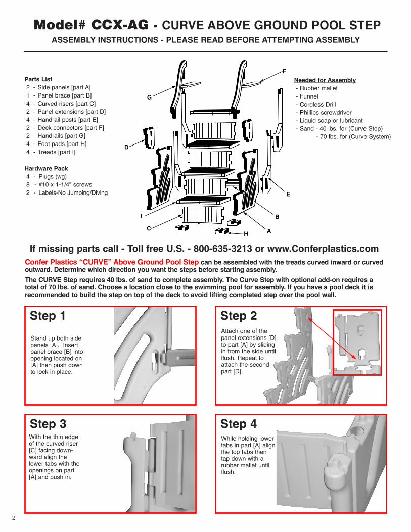
Stand up both sidepanels [A]. Insertpanel brace [B] intoopening located on[A] then push downto lock in place.
Step 1Attach one of thepanel extensions [D]to part [A] by slidingin from the side untilflush. Repeat toattach the secondpart [D].
Step 2
With the thin edgeof the curved riser[C] facing down-ward align thelower tabs with theopenings on part[A] and push in.
Step 3While holding lowertabs in part [A] alignthe top tabs thentap down with arubber mallet untilflush.
Step 4
Confer Plastics “CURVE” Above Ground Pool Step can be assembled with the treads curved inward or curvedoutward. Determine which direction you want the steps before starting assembly.
The CURVE Step requires 40 lbs. of sand to complete assembly. The Curve Step with optional add-on requires atotal of 70 lbs. of sand. Choose a location close to the swimming pool for assembly. If you have a pool deck it isrecommended to build the step on top of the deck to avoid lifting completed step over the pool wall.
Hardware Pack4 - Plugs (wg)8 - #10 x 1-1/4" screws2 - Labels-No Jumping/Diving
Needed for Assembly- Rubber mallet- Funnel- Cordless Drill- Phillips screwdriver- Liquid soap or lubricant- Sand - 40 lbs. for (Curve Step)
- 70 lbs. for (Curve System)
Model# CCX-AG - CURVE ABOVE GROUND POOL STEP ASSEMBLY INSTRUCTIONS - PLEASE READ BEFORE ATTEMPTING ASSEMBLY
Parts List2 - Side panels [part A]1 - Panel brace [part B]4 - Curved risers [part C]2 - Panel extensions [part D]4 - Handrail posts [part E]2 - Deck connectors [part F]2 - Handrails [part G]4 - Foot pads [part H]4 - Treads [part I]
If missing parts call - Toll free U.S. - 800-635-3213 or www.Conferplastics.com
prpd.Confer-CurveStepAG-USr11:Confer-Step-1_R1 2/19/13 2:55 PM Page 2
3
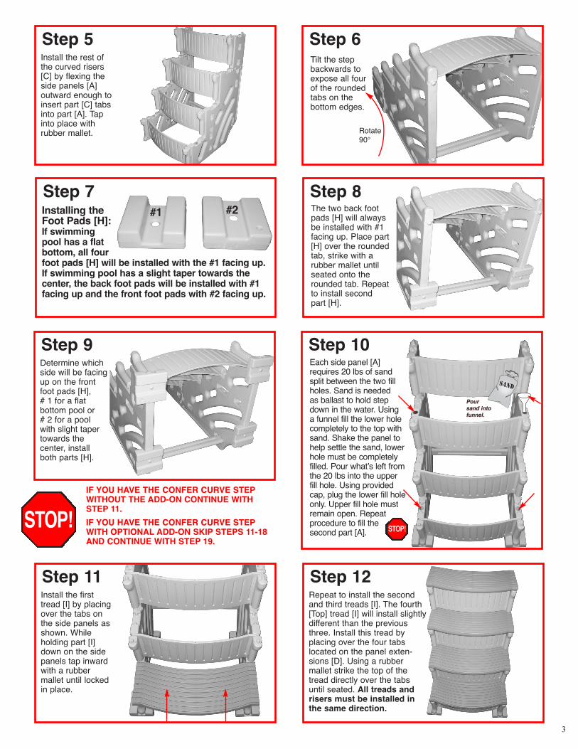
IF YOU HAVE THE CONFER CURVE STEPWITHOUT THE ADD-ON CONTINUE WITHSTEP 11.
IF YOU HAVE THE CONFER CURVE STEPWITH OPTIONAL ADD-ON SKIP STEPS 11-18AND CONTINUE WITH STEP 19.
Install the rest ofthe curved risers[C] by flexing theside panels [A] outward enough toinsert part [C] tabsinto part [A]. Tapinto place with rubber mallet.
Step 5Tilt the stepbackwards toexpose all fourof the roundedtabs on thebottom edges.
Step 6
Rotate90°
Determine whichside will be facingup on the frontfoot pads [H], # 1 for a flat bottom pool or # 2 for a pool with slight tapertowards the center, installboth parts [H].
Step 9Each side panel [A]requires 20 lbs of sandsplit between the two fillholes. Sand is needed as ballast to hold stepdown in the water. Using a funnel fill the lower holecompletely to the top withsand. Shake the panel tohelp settle the sand, lowerhole must be completelyfilled. Pour whatʼs left fromthe 20 lbs into the upper fill hole. Using providedcap, plug the lower fill holeonly. Upper fill hole mustremain open. Repeatprocedure to fill thesecond part [A].
Step 10
Installing theFoot Pads [H]:If swimmingpool has a flatbottom, all fourfoot pads [H] will be installed with the #1 facing up.If swimming pool has a slight taper towards thecenter, the back foot pads will be installed with #1facing up and the front foot pads with #2 facing up.
Step 7The two back footpads [H] will alwaysbe installed with #1facing up. Place part[H] over the roundedtab, strike with a rubber mallet untilseated onto therounded tab. Repeatto install second part [H].
Step 8
SAND
Pour sand intofunnel.
Pour sand intofunnel.
Install the firsttread [I] by placingover the tabs onthe side panels asshown. Whileholding part [I]down on the sidepanels tap inwardwith a rubber mallet until lockedin place.
Step 11Repeat to install the secondand third treads [I]. The fourth[Top] tread [I] will install slightlydifferent than the previousthree. Install this tread by placing over the four tabslocated on the panel exten-sions [D]. Using a rubber mallet strike the top of thetread directly over the tabsuntil seated. All treads andrisers must be installed inthe same direction.
Step 12
#1 #2
STOP! STOP!
prpd.Confer-CurveStepAG-USr11:Confer-Step-1_R1 2/19/13 2:55 PM Page 3
4
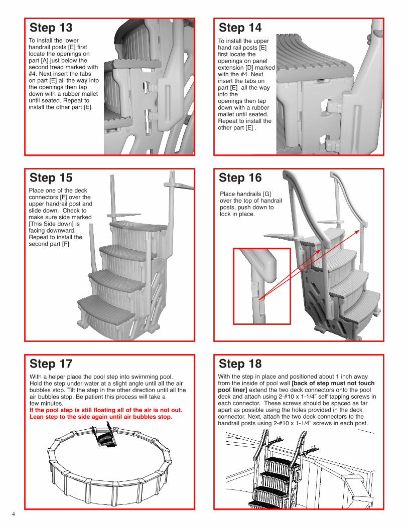
To install the lowerhandrail posts [E] firstlocate the openings onpart [A] just below thesecond tread marked with#4. Next insert the tabson part [E] all the way intothe openings then tapdown with a rubber malletuntil seated. Repeat toinstall the other part [E].
Step 13To install the upperhand rail posts [E]first locate the openings on panelextension [D] markedwith the #4. Nextinsert the tabs onpart [E] all the wayinto the openings then tapdown with a rubbermallet until seated.Repeat to install theother part [E] .
Step 14
Place one of the deckconnectors [F] over theupper handrail post andslide down. Check tomake sure side marked[This Side down] is facing downward.Repeat to install the second part [F]
Step 15 Step 16
Step 17With the step in place and positioned about 1 inch awayfrom the inside of pool wall [back of step must not touchpool liner] extend the two deck connectors onto the pooldeck and attach using 2-#10 x 1-1/4” self tapping screws ineach connector. These screws should be spaced as farapart as possible using the holes provided in the deck connector. Next, attach the two deck connectors to thehandrail posts using 2-#10 x 1-1/4” screws in each post.
Step 18With a helper place the pool step into swimming pool. Hold the step under water at a slight angle until all the airbubbles stop. Tilt the step in the other direction until all theair bubbles stop. Be patient this process will take a few minutes.If the pool step is still floating all of the air is not out.Lean step to the side again until air bubbles stop.
Place handrails [G]over the top of handrailposts, push down tolock in place.
prpd.Confer-CurveStepAG-USr11:Confer-Step-1_R1 2/19/13 2:55 PM Page 4

Install the add-on panel [J]by inserting the three tabsinto the three openingslocated towards the backof step panel [A]. Push the tabs all the way in, then tap panel down with a rubber mallet until seated in openings.
Step 19Next, install one of the foot pads [H] onto the tab located on the bottom ofthe large flex riser [M] by placing overthe raised tab and striking with a rubbermallet until seated. Foot pad [H]should be installed in the same direction as the front foot pads on base step.[Refer to steps 7 & 9].
Step 20
Tilt the step back farenough to slide theend of large flex riser[M] up into the slotlocated on the frontbottom edge of theadd-on side panel.
Step 21Insert the tab onthe other end ofthe flex riser [M]into the openingon side panel [A].
Step 22
Attach the last footpad [H] on to the bottom of the treadsupport [N] by placingover the raised taband striking with arubber mallet untilseated. Foot pad [H]should be installedin the same positionas the front footpads on base step.
Step 23Locate the notch onthe bottom edge ofthe large flex riser[M]. Slide the stepsupport [N] underthen rotate up makingsure part is in notch.
Step 24
5
T
S
L
K
J
R
Q
P
M
H
N
O
U
Additional Parts for Step Add-On2 - Foot pads [Part H]1 - Add-on panel [Part J]1 - Short hand rail post [Part K]1 - Long hand rail post [Part L]1 - Large flex riser [Part M]1 - Tread support [Part N]1 - Large curved tread [Part O]
1 - Medium flex riser [Part P]1 - Medium curved tread [Part Q]1 - Small flex riser [Part R]1 - Small curved tread [Part S]1 - Tread filler [Part T]1 - Tread extension [Part U]2 - Plugs [WG] (installed in add-on panel)
CONFER CURVE STEP ADD-ON INSTRUCTIONS
The curve add-on can only be installed on the right side of the step as youare facing it. The add-on requires an additional 30 lbs. of sand.
prpd.Confer-CurveStepAG-USr11:Confer-Step-1_R1 2/19/13 2:55 PM Page 5
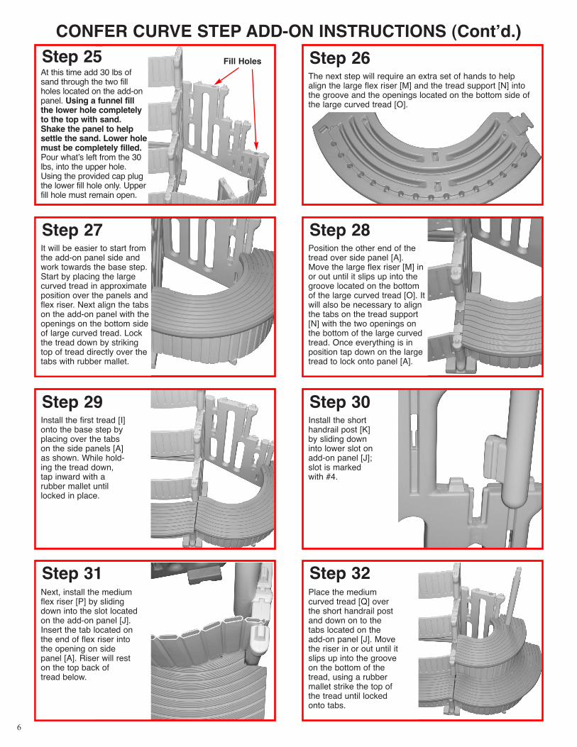
Position the other end of thetread over side panel [A].Move the large flex riser [M] inor out until it slips up into thegroove located on the bottomof the large curved tread [O]. Itwill also be necessary to alignthe tabs on the tread support[N] with the two openings onthe bottom of the large curvedtread. Once everything is inposition tap down on the largetread to lock onto panel [A].
Step 28
Install the first tread [I]onto the base step byplacing over the tabson the side panels [A]as shown. While hold-ing the tread down,tap inward with a rubber mallet untillocked in place.
Step 29Install the shorthandrail post [K]by sliding downinto lower slot onadd-on panel [J];slot is marked with #4.
Step 30
Place the mediumcurved tread [Q] overthe short handrail postand down on to thetabs located on theadd-on panel [J]. Movethe riser in or out until itslips up into the grooveon the bottom of thetread, using a rubbermallet strike the top ofthe tread until lockedonto tabs.
Step 32
CONFER CURVE STEP ADD-ON INSTRUCTIONS (Contʼd.)
At this time add 30 lbs ofsand through the two fillholes located on the add-onpanel. Using a funnel fillthe lower hole completelyto the top with sand.Shake the panel to helpsettle the sand. Lower holemust be completely filled.Pour whatʼs left from the 30lbs, into the upper hole.Using the provided cap plugthe lower fill hole only. Upperfill hole must remain open.
Step 25The next step will require an extra set of hands to helpalign the large flex riser [M] and the tread support [N] intothe groove and the openings located on the bottom side ofthe large curved tread [O].
Step 26Fill Holes
It will be easier to start fromthe add-on panel side andwork towards the base step.Start by placing the largecurved tread in approximateposition over the panels andflex riser. Next align the tabson the add-on panel with theopenings on the bottom sideof large curved tread. Lockthe tread down by strikingtop of tread directly over thetabs with rubber mallet.
Step 27
Next, install the mediumflex riser [P] by slidingdown into the slot locatedon the add-on panel [J].Insert the tab located onthe end of flex riser intothe opening on sidepanel [A]. Riser will reston the top back of tread below.
Step 31
6
prpd.Confer-CurveStepAG-USr11:Confer-Step-1_R1 2/19/13 2:55 PM Page 6

CONFER CURVE STEP ADD-ON INSTRUCTIONS (Contʼd.)Install the second tread[I] onto the base step Step 33
Install the long handrailpost [L] into the upperslot on add-on panel,
slot is marked with #4.
Step 34Repeat step 31 to install the small flex riser [R] then place the small
curved tread [S] over the handrail post and attach the same as step 32.
Step 35
Install the thirdtread [I] ontothe base step
Step 36Slide the tread filler [T]down between the handrail post and panel.
Step 37Attach the tread extension[U] onto the step panel [A].
Step 38
The last [Top] treadinstalls differentfrom the previousthree. To install thelast tread [I] placeover the four tabslocated on panelextension [D].Using a rubbermallet strike thetop of the treaddirectly over thetabs until seated.
Step 39Install the two handrailposts [E] into side panel[A] by following steps 13
and 14. The other two handrail posts [E] will not be used, save as spare parts
or recycle.
Step 40Place one of thedeck connectors[F] over theupper hand railpost and slidedown. Check tomake sure [Thisside down] isfacing down-ward. Repeat to install the second part [F].
Step 41
Place handrails[G] over the topof handrail postsand push downto lock in place.
Step 42FOLLOW STEPS17 AND 18 TOPLACE STEP IN POOL.
7
prpd.Confer-CurveStepAG-USr11:Confer-Step-1_R1 2/19/13 2:55 PM Page 7

CP-CURVE STEP-AG 11-128
Safety Information1) Always follow the manufacturerʼs
recommendations for the safe use of all handtools and equipment.
2). Do not use the Confer Curve Step for anypurpose other than that for which it is intended.
3). When lifting awkward or heavy loads, haveanother person help you.
4). Maximum weight on steps not to exceed 400 lbs.
5). WARNING: Exceeding the recommended weightrestriction may cause the unit to fail.
6). Consult your local building department beforeinstallation of your pool and equipment.
TO WINTERIZE YOUR POOLWe suggest removing your Confer Curve Step from the poolfor the off-season months.
If your Confer Curve Step is attached to a deck: Two peopleare required for this operation and it is best to remove theunit while the water is still warm enough so that one personcan get into the pool. Disconnect the mounting bracketsfrom the deck. The person in the water can lift the unit upwhile the person on the deck helps to pull and guide the unitonto the deck. After the unit is on the deck, and the waterhas drained out of the steps, lay the unit on itʼs back side sothat most of the water drains from the side panels.
If getting into the water is not an option the unit can beremoved by both people standing on the deck and lifting andtilting the unit to drain some of the water from the steps. Afterthe unit is light enough carefully lift it from the pool.
CAUTION: POOL STEP WILL BE HEAVY, PLEASE HAVEADDITIONAL HELP WHEN REMOVING FROMSWIMMING POOL. DO NOT ATTEMPT TO REMOVESTEP BY YOURSELF.
The Confer Curve Step can be covered, if desired, andstored outdoors.
Printed in U.S.A.
MADE IN THE U.S.A. by:
CONFER PLASTICS, INC. FIVE YEAR WARRANTYConfer Plastics, Inc. warrants their swimming pool ladders and steps to be free from defects inworkmanship for five years from date of purchase.
DO NOT RETURN DEFECTIVE PART TO DEALERE-MAIL CONFER PLASTICS AT: [email protected]
A PICTURE [S] OF DEFECTIVE PART, A BRIEF DESCRIPTION OF PROBLEM, PROOF OF PURCHASE AND YOUR CONTACT INFORMATION.
INFORMATION MAY ALSO BE FAXED TO CONFER PLASTICS AT: 716-694-3102OR MAILED TO THE ADDRESS BELOW. UPON REVIEW OF THE INFORMATION YOU
WILL BE NOTIFIED IF PART IS COVERED UNDER THE WARRANTY AND THE SHIPPING/HANDLING CHARGES.
This warranty gives you specific legal rights, and you may also have other rights which may vary from state to state.
Confer Plastics, Inc.97 Witmer Road
North Tonawanda, N.Y. 14120-2421
97 Witmer RoadNorth Tonawanda, New York 14120-2421Toll Free U.S. 800-635-3213FAX 716-694-3102www.conferladders.com
prpd.Confer-CurveStepAG-USr11:Confer-Step-1_R1 2/19/13 2:55 PM Page 8