Embed Size (px)
Citation preview

181 MERCER STREET NEW YORK, NEW YORK
Remedial Action Work Plan
NYC VCP Project Number 17CVCP040M
OER Project Number 15RHAN111M
Restrictive Declaration Number R-218
Prepared For:
New York University
Facilities and Construction Management
10 Astor Place, 6th
Floor
New York, New York
212-998-1424
Prepared By:
Langan Engineering, Environmental, Surveying and
Landscape Architecture, D.P.C.
21 Penn Plaza, 360 West 31st street, 8
th Floor
New York, New York
212-479-5400
JANUARY 2017
i
REMEDIAL ACTION WORK PLAN
TABLE OF CONTENTS
APPENDICES........................................................................................................................... ii
LIST OF ACRONYMS ........................................................................................................... iii
CERTIFICATION.....................................................................................................................v
EXECUTIVE SUMMARY .....................................................................................................vi
REMEDIAL ACTION WORK PLAN .................................................................................... 1
1.0 Project Background.........................................................................................................1
1.2 Redevelopment Plan .......................................................................................................... 2
1.3 Description of Surrounding Property ............................................................................... 3
1.4 Summary of Past Site Uses and Areas of Concern .......................................................... 4
1.6 Summary of Findings of Remedial Investigation ............................................................ 6
2.0 Remedial Action Objectives ...........................................................................................8
3.0 Remedial Alternatives Analysis .....................................................................................9
3.1 Threshold Criteria Protection of Public Health and the Environment.......................... 11
3.2 Balancing Criteria ............................................................................................................ 12
4.0 Remedial Action ............................................................................................................ 20
4.1 Summary of Preferred Remedial Action ........................................................................ 20
4.2 Soil Cleanup Objectives and Soil/ Fill Management..................................................... 23
4.3 Engineering Controls ....................................................................................................... 26
4.4 Institutional Controls ....................................................................................................... 27
4.5 Site Management Plan ..................................................................................................... 28
4.6 Qualitative Human Health Exposure Assessment ......................................................... 28
5.0 Remedial Action Management.................................................................................... 35
5.1 Project Organization and Oversight................................................................................ 35
5.2 Site Security ..................................................................................................................... 35
5.3 Work Hours ...................................................................................................................... 35
5.4 Construction Health and Safety Plan .............................................................................. 35
5.5 Community Air Monitoring Plan.................................................................................... 36
5.6 Agency Approvals ........................................................................................................... 38
5.7 Site Preparation ................................................................................................................ 39
ii
5.8 Traffic Control ................................................................................................................. 43
5.9 Demobilization................................................................................................................. 43
5.10 Reporting and Record Keeping....................................................................................... 43
5.11 Complaint Management .................................................................................................. 44
5.12 Deviations from the Remedial Action Work Plan ......................................................... 45
6.0 Remedial Action Report .............................................................................................. 46
7.0 Schedule.......................................................................................................................... 49
FIGURES
Figure 1: Site Location Map
Figure 2: Site Boundary Map
Figure 3: Surrounding Land Usage
Figure 4: Site Excavation Diagram
Figure 5: Endpoint Sampling Diagram
Figure 6: Composite Cover and Vapor Barrier Design Drawing
Figure 7: Truck Route
TABLES
Table 1: Summary of Track 1 SCOs
APPENDICES
Appendix 1: Proposed Development Plans
Appendix 2: Remedial Investigation Report
Appendix 3: Citizen Participation Plan
Appendix 4: Sustainability Statement
Appendix 5: Soil/Materials Management Plan
Appendix 6: Manufacturer Specifications for Vapor Barrier
Appendix 7: Construction Health and Safety Plan
iii
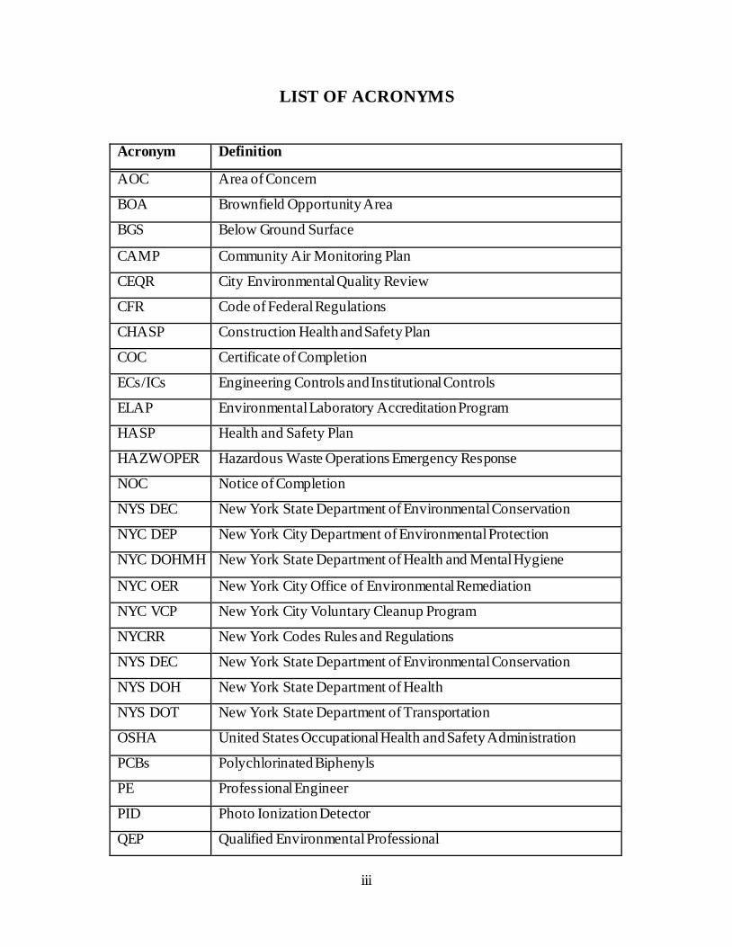
LIST OF ACRONYMS
Acronym Definition
AOC Area of Concern
BOA Brownfield Opportunity Area
BGS Below Ground Surface
CAMP Community Air Monitoring Plan
CEQR City Environmental Quality Review
CFR Code of Federal Regulations
CHASP Construction Health and Safety Plan
COC Certificate of Completion
ECs/ICs Engineering Controls and Institutional Controls
ELAP Environmental Laboratory Accreditation Program
HASP Health and Safety Plan
HAZWOPER Hazardous Waste Operations Emergency Response
NOC Notice of Completion
NYS DEC New York State Department of Environmental Conservation
NYC DEP New York City Department of Environmental Protection
NYC DOHMH New York State Department of Health and Mental Hygiene
NYC OER New York City Office of Environmental Remediation
NYC VCP New York City Voluntary Cleanup Program
NYCRR New York Codes Rules and Regulations
NYS DEC New York State Department of Environmental Conservation
NYS DOH New York State Department of Health
NYS DOT New York State Department of Transportation
OSHA United States Occupational Health and Safety Administration
PCBs Polychlorinated Biphenyls
PE Professional Engineer
PID Photo Ionization Detector
QEP Qualified Environmental Professional
iv
RAOs Remedial Action Objectives
RAR Remedial Action Report
RAWP Remedial Action Work Plan or Plan
RCA Recycled Concrete Aggregate
RD Remedial Design
RI Remedial Investigation
RR Restricted Residential
SCOs Soil Cleanup Objectives
SCG Standards, Criteria and Guidance
SGV NYSDEC Technical and Operational Guidance 1.1.1 Ambient Water
Quality Standards and Guidance Values
SMP Site Management Plan
SPDES State Pollutant Discharge Elimination System
SSDS Sub-Slab Depressurization System
SVOC Semi-Volatile Organic Compound
TAL Target Analyte List
TCL Target Compound List
USGS United States Geological Survey
UST Underground Storage Tank
UU Unrestricted Use
VOC Volatile Organic Compound
v
CERTIFICATION
I, Jason Hayes, am currently a registered professional engineer licensed by the State of New York. I performed
professional engineering services and had primary direct responsibility for designing the remedial program for the
181 Mercer Street site, site number 17CVCP040M. I certify to the following:
I have reviewed this document and the Stipulation List, to which my signature and seal are affixed.
Engineering Controls developed for this remedial action were designed by me or a person under my direct
supervision and designed to achieve the goals established in this Remedial Action Work Plan for this site.
The Engineering Controls to be constructed during this remedial action are accurately reflected in the text and drawings of the Remedial Action Work Plan and are of sufficient detail to enable proper construction .
This Remedial Action Work Plan (RAWP) has a plan for handling, transport and disposal of soil, fill, fluids
and other materials removed from the property in accordance with applicable City, State and Federal laws
and regulations. This RAWP also has a plan for importation of all soil, fill and other material from off-Site
that is in accordance with all applicable City, State and Federal laws and requirements. This RAWP has
provisions to control nuisances during the remediation and all invasive work, including dust and odor
suppression.
DRAFT
_________ Name
PE License Number
Signature
Date
I, Michael Burke, am a qualified Environmental Professional. I will have primary direct responsibility for
implementation of the remedial program for the 181 Mercer Street site, site number 17CVCP040M . I certify to the
following:
This Remedial Action Work Plan (RAWP) has a plan for handling, transport and disposal of soil, fill, fluids
and other materials removed from the property in accordance with applicable City, State and Federal laws and regulations. This RAWP also has a plan for importation of all soil, fill and other material from off-Site
that is in accordance with all applicable City, State and Federal laws and requirements. This RAWP has
provisions to control nuisances during the remediation and all invasive work, including dust and odor
suppression.
DRAFT
QEP Name
QEP Signature
Date
PE Stamp
vi
EXECUTIVE SUMMARY
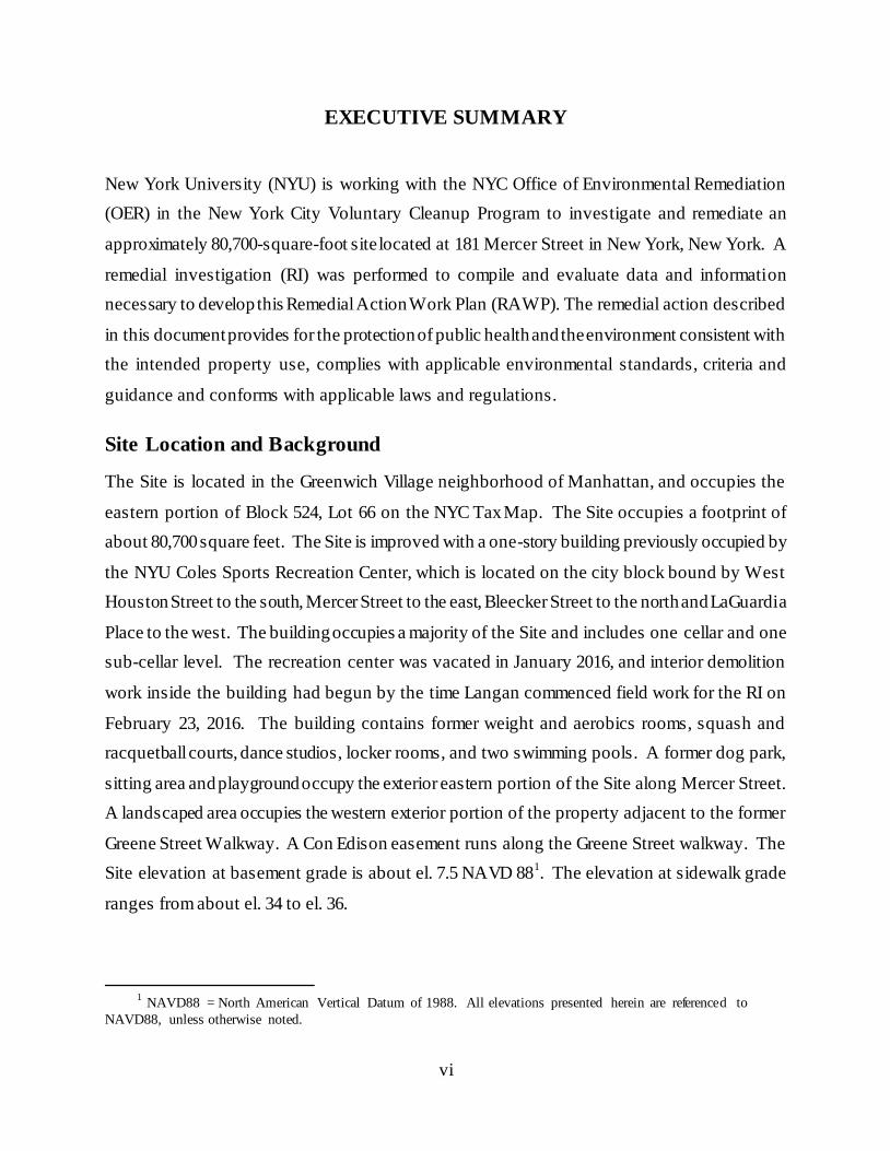
New York University (NYU) is working with the NYC Office of Environmental Remediation
(OER) in the New York City Voluntary Cleanup Program to investigate and remediate an
approximately 80,700-square-foot site located at 181 Mercer Street in New York, New York. A
remedial investigation (RI) was performed to compile and evaluate data and information
necessary to develop this Remedial Action Work Plan (RAWP). The remedial action described
in this document provides for the protection of public health and the environment consistent with
the intended property use, complies with applicable environmental standards, criteria and
guidance and conforms with applicable laws and regulations.
Site Location and Background
The Site is located in the Greenwich Village neighborhood of Manhattan, and occupies the
eastern portion of Block 524, Lot 66 on the NYC Tax Map. The Site occupies a footprint of
about 80,700 square feet. The Site is improved with a one-story building previously occupied by
the NYU Coles Sports Recreation Center, which is located on the city block bound by West
Houston Street to the south, Mercer Street to the east, Bleecker Street to the north and LaGuardia
Place to the west. The building occupies a majority of the Site and includes one cellar and one
sub-cellar level. The recreation center was vacated in January 2016, and interior demolition
work inside the building had begun by the time Langan commenced field work for the RI on
February 23, 2016. The building contains former weight and aerobics rooms, squash and
racquetball courts, dance studios, locker rooms, and two swimming pools. A former dog park,
sitting area and playground occupy the exterior eastern portion of the Site along Mercer Street.
A landscaped area occupies the western exterior portion of the property adjacent to the former
Greene Street Walkway. A Con Edison easement runs along the Greene Street walkway. The
Site elevation at basement grade is about el. 7.5 NAVD 881. The elevation at sidewalk grade
ranges from about el. 34 to el. 36.
1 NAVD88 = North American Vertical Datum of 1988. All elevations presented herein are referenced to
NAVD88, unless otherwise noted.
vii
The redevelopment project is subject to a “Restrictive Declaration of Large -Scale General
Development for the NYU LSGD”, dated July 24, 2012. The Restrictive Declaration (R-218)
covers the phased redevelopment of four contiguous lots (two super blocks) owned by NYU.
The Site occupies the southeastern portion of the redevelopment area and constitutes the first
phase of redevelopment. The Restrictive Declaration applies to hazardous materials, air quality,
and noise concerns. A site location plan is presented in Figure 1. A site boundary map is
provided in Figure 2.
Summary of Redevelopment Plan
The proposed future use of the Site will include demolition of the existing building and paved
exterior areas to construct a new building that will house facilities for NYU students and faculty.
The proposed development will consist of a six-story podium, upon which will be five towers up
to 23-stories high. The building will include two sub-grade levels and will require excavation of
the entire site footprint to about 6.5 feet below the existing sub-grade level (i.e., el. 1.0), which is
about 34 feet below sidewalk grade The cellar and sub-cellar will be extended about 12 feet
west of the current western boundary of the building. Construction of a swimming pool,
stormwater tank, ejector pit, two elevator pits, and mechanical plenum will require deeper
excavation to elevations ranging from about el. -3.0 to -8.5 (i.e., 38 to 42.5 feet below sidewalk
grade) in portions of the site. The new building will contain student and faculty housing,
commercial space, theaters, dining areas, performing arts venues, athletic areas, gymnasiums and
classrooms. The 5,600-square-foot Greene Street Walkway will be repaved, and a landscaping
cover will be placed on the 2,600-square-foot northern exterior area bordering Bleecker Street .
The cellar will house locker rooms, meeting rooms, office space and a performing arts theater.
The sub-cellar will contain four basketball courts, a pool, a wrestling and martial arts studio,
equipment and athletic laundry rooms, storage for athletic equipment and pool supplies,
mechanical rooms and additional locker rooms .
viii
The proposed development plans are provided in Appendix 1. The remedial action contemplated
under this RAWP may be implemented independently of the proposed redevelopment plan.
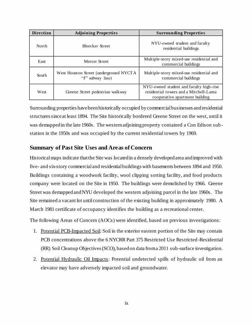
Summary of Surrounding Property
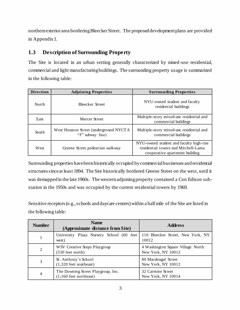
The Site is located in an urban setting generally characterized by mixed -use residential,
commercial and light manufacturing buildings. The surrounding property usage is summarized
in the following table:
ix
Direction Adjoining Properties Surrounding Properties
North Bleecker Street NYU-owned student and faculty
residential buildings
East Mercer Street Multiple-story mixed-use residential and
commercial buildings
South West Houston Street (underground NYCTA
“F” subway line)
Multiple-story mixed-use residential and
commercial buildings
West Greene Street pedestrian walkway
NYU-owned student and faculty high-rise
residential towers and a Mitchell-Lama
cooperative apartment building
Surrounding properties have been historically occupied by commercial businesses and residential
structures since at least 1894. The Site historically bordered Greene Street on the west, until it
was demapped in the late 1960s. The western adjoining property contained a Con Edison sub -
station in the 1950s and was occupied by the current residential towers by 1969.
Summary of Past Site Uses and Areas of Concern
Historical maps indicate that the Site was located in a densely developed area and improved with
five- and six-story commercial and residential buildings with basements between 1894 and 1950.
Buildings containing a woodwork facility, wool clipping sorting facility, and food products
company were located on the Site in 1950. The buildings were demolished by 1966. Greene
Street was demapped and NYU developed the western adjoining parcel in the late 1960s. The
Site remained a vacant lot until construction of the existing building in approximately 1980. A
March 1981 certificate of occupancy identifies the building as a recreational center.
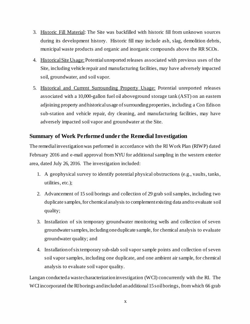
The following Areas of Concern (AOCs) were identified, based on previous investigations:
1. Potential PCB-Impacted Soil: Soil in the exterior eastern portion of the Site may contain
PCB concentrations above the 6 NYCRR Part 375 Restricted Use Restricted -Residential
(RR) Soil Cleanup Objectives (SCO), based on data from a 2011 sub-surface investigation.
2. Potential Hydraulic Oil Impacts: Potential undetected spills of hydraulic oil from an
elevator may have adversely impacted soil and groundwater.
x
3. Historic Fill Material: The Site was backfilled with historic fill from unknown sources
during its development history. Historic fill may include ash, slag, demolition debris,
municipal waste products and organic and inorganic compounds above the RR SCOs.
4. Historical Site Usage: Potential unreported releases associated with previous uses of the
Site, including vehicle repair and manufacturing facilities, may have adversely impacted
soil, groundwater, and soil vapor.
5. Historical and Current Surrounding Property Usage: Potential unreported releases
associated with a 10,000-gallon fuel oil aboveground storage tank (AST) on an eastern
adjoining property and historical usage of surrounding properties, including a Con Edison
sub-station and vehicle repair, dry cleaning, and manufacturing facilities, may have
adversely impacted soil vapor and groundwater at the Site.
Summary of Work Performed under the Remedial Investigation
The remedial investigation was performed in accordance with the RI Work Plan (RIWP) dated
February 2016 and e-mail approval from NYU for additional sampling in the western exterior
area, dated July 26, 2016. The investigation included:
1. A geophysical survey to identify potential physical obstructions (e.g., vaults, tanks,
utilities, etc.);
2. Advancement of 15 soil borings and collection of 29 grab soil samples, including two
duplicate samples, for chemical analysis to complement existing data and to evaluate soil
quality;
3. Installation of six temporary groundwater monitoring wells and collection of seven
groundwater samples, including one duplicate sample, for chemical analysis to evaluate
groundwater quality; and
4. Installation of six temporary sub-slab soil vapor sample points and collection of seven
soil vapor samples, including one duplicate, and one ambient air sample, for chemical
analysis to evaluate soil vapor quality.
Langan conducted a waste characterization investigation (WCI) concurrently with the RI. The
WCI incorporated the RI borings and included an additional 15 soil borings, from which 66 grab
xi
and 67 composite samples were collected. Composite samples generally included material from
two to three borings. The samples were representative of discrete depth intervals within the
historic fill material and underlying native soil.
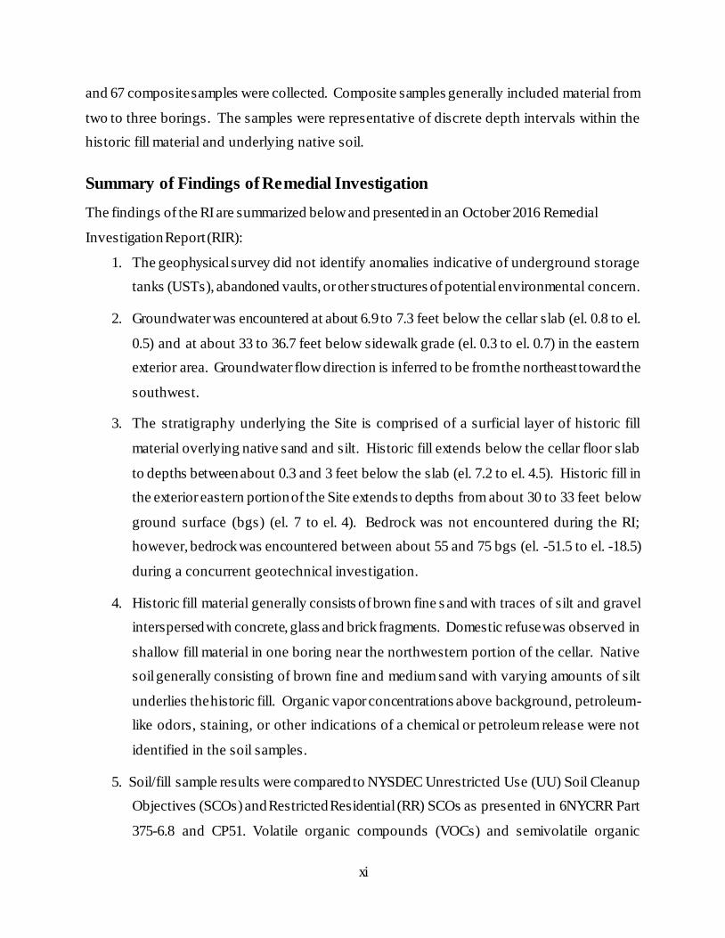
Summary of Findings of Remedial Investigation
The findings of the RI are summarized below and presented in an October 2016 Remedial
Investigation Report (RIR):
1. The geophysical survey did not identify anomalies indicative of underground storage
tanks (USTs), abandoned vaults, or other structures of potential environmental concern.
2. Groundwater was encountered at about 6.9 to 7.3 feet below the cellar slab (el. 0.8 to el.
0.5) and at about 33 to 36.7 feet below sidewalk grade (el. 0.3 to el. 0.7) in the eastern
exterior area. Groundwater flow direction is inferred to be from the northeast toward the
southwest.
3. The stratigraphy underlying the Site is comprised of a surficial layer of historic fill
material overlying native sand and silt. Historic fill extends below the cellar floor slab
to depths between about 0.3 and 3 feet below the slab (el. 7.2 to el. 4.5). Historic fill in
the exterior eastern portion of the Site extends to depths from about 30 to 33 feet below
ground surface (bgs) (el. 7 to el. 4). Bedrock was not encountered during the RI;
however, bedrock was encountered between about 55 and 75 bgs (el. -51.5 to el. -18.5)
during a concurrent geotechnical investigation.
4. Historic fill material generally consists of brown fine s and with traces of silt and gravel
interspersed with concrete, glass and brick fragments. Domestic refuse was observed in
shallow fill material in one boring near the northwestern portion of the cellar. Native
soil generally consisting of brown fine and medium sand with varying amounts of silt
underlies the historic fill. Organic vapor concentrations above background, petroleum-
like odors, staining, or other indications of a chemical or petroleum release were not
identified in the soil samples.
5. Soil/fill sample results were compared to NYSDEC Unrestricted Use (UU) Soil Cleanup
Objectives (SCOs) and Restricted Residential (RR) SCOs as presented in 6NYCRR Part
375-6.8 and CP51. Volatile organic compounds (VOCs) and semivolatile organic
xii
compounds (SVOCs) were detected at or below the UU SCOs. Samples of historical fill
material contained the pesticide 4,4’-DDT (max 0.03 mg/kg), and the polychlorinated
biphenyls (PCBs) Aroclor 1254 and Aroclor 1260 (total PCBs 1.11 mg/kg) were
detected at concentrations above the UU SCOs and below the RR SCOs. Four metals,
including lead (max 82.2 mg/kg), mercury (max 0.399 mg/kg), nickel (max 31.9 mg/kg)
and zinc (max 164 mg/kg), were detected at concentrations above the UU SCOs and
below the RR SCOs. Samples of native soil did not contain compounds above the UU
SCOs.
6. Groundwater sample results were compared to 6NYCRR Part 703.5 Class GA
groundwater quality standards (GQS). One groundwater sample (MW21) contained
chloroform (max 8 µg/l) and tetrachloroethylene (PCE) (max 6.3 µg/l) at concentrations
above their respective GQS. Chloroform is a common byproduct of the chlorination
process for drinking water, and PCE is a chlorinated solvent that was historically used in
the commercial dry cleaning process. Four dissolved metals (antimony, manganese,
magnesium, and sodium) were detected in at least one of the six wells at concentrations
above the GQS. The presence of manganese, magnesium, and sodium in each well
indicates that the detections are likely attributable to a regional groundwater condition.
The antimony detection does not correlate with detections in soil samples from the same
boring (EB16) or with detections in other groundwater samples. The occurrence may
therefore reflect a localized condition.
7. Sub-slab soil vapor sample analytical results were evaluated based on the Decision
Matrices presented in the 2006 New York State Department of Health (NYSDOH)
Guidance for Evaluating Soil Vapor Intrusion in the State of New York and the 2013 and
2015 NYSDOH Ambient Air Guideline updates for trichloroethene (TCE) and
tetrachloroethene (PCE). Three of the seven compounds covered by the Decision
Matrices were detected: carbon tetrachloride (max 3 μg/m3), TCE (max 12 μg/m
3), and
PCE (max 6.5 μg/m3). The NYSDOH mitigation recommendations include “no further
action” to “monitor” and “mitigate”, based on the detected soil vapor concentrations.
xiii
Summary of the Remedial Action
The proposed remedial action achieves protection of public health and the environment for the
intended use of the property. The proposed remedial action achieves all of the remedial act ion
objectives established for the project and addresses applicable standards, criterion, and guidance;
is effective in both the short-term and long-term and reduces mobility, toxicity and volume of
contaminants; is cost effective and implementable; and us es standards methods that are well
established in the industry.
The proposed remedial action will consist of:
1. Preparation of a Community Protection Statement and performance of all required
NYC VCP Citizen Participation activities , according to an approved Citizen
Participation Plan.
2. Performance of a Community Air Monitoring Program for particulates and volatile
organic carbon compounds.
3. Selection of NYSDEC Part 375 Unrestricted Use (Track 1) SCOs.
4. Site mobilization involving Site security setup, equipment mobilization, utility mark
outs and marking & staking excavation areas.
5. Completion of a Waste Characterization Study prior to excavation . A Waste
Characterization Study was completed during the RI and additional sampling will be
conducted as required for soil disposal facility approval. Waste characterization soil
samples were collected at a frequency of about one sample per 800 (approximate) cubic
yards of fill to be excavated. A Waste Characterization Report documenting sample
procedures, location and analytical results shall be submitted to OER as part of the
Remedial Action Report (RAR).
6. Excavation and removal of soil and fill exceeding Track 1 Unrestricted Use SCOs
during installation of the temporary support of excavation (SOE) system along the
northern, eastern and western perimeters of the Site. Soldier piles will be drilled to a
depth of about 48 to 50 feet below sidewalk grade (el. -15.0). The eastern and western
exterior portions of the Site will be excavated to the planned sub-grade elevation (el.
1.0), which is about 6.5 feet below the existing sub-grade level and about 34 feet below
sidewalk grade. The below-ground portions of the existing building will be demolished
xiv
during this phase. Approximately 22,000 cubic yards (CY) of soil will be removed
during the SOE phase.
7. Excavation and removal of soil and fill exceeding Track 1 Unrestricted Use SCOs
during bulk excavation in the footprint of the existing building. The footprint of the
former building will be excavated from the existing level (el. 7.5) to the sub -cellar
foundation slab elevation (el. 1.0), which is about 6.5 feet below the existing sub-grade
level and about 34 feet below sidewalk grade. Deeper excavation will occur in the
areas of the proposed swimming pool (el. -3.3 or about 37.5 feet below sidewalk
grade), the elevator pits (el. -4.7 or about 38.5 feet below sidewalk grade) and caissons
and caps (el. -1.5 and -5.0 or about 35.5 and 39 feet below sidewalk grade).
Approximately 16,000 CY of soil will be removed during this phase.
8. Screening of excavated soil and fill during intrusive work for indications of
contamination by visual means, odor, and monitoring with a PID. Appropriate
segregation of excavated media on-Site.
9. Management of excavated materials including temporarily stockpiling and segregating
in accordance with defined material types and to prevent co-mingling of different waste
streams.
10. Removal of underground storage tanks encountered during soil and fill removal
activities. Registration of tanks, reporting of petroleum spills associated with USTs,
and appropriate closure of these petroleum spills in compliance with applicable local,
state and federal laws and regulations.
11. Transportation and off-Site disposal of soil and fill material at licensed or permitted
facilities in accordance with applicable laws and regulations for handling, transport, and
disposal, and this plan. Sampling and analysis of excavated media as required by
disposal facilities. Appropriate segregation of excavated media on -Site.
12. Collection and analysis of end-point samples to determine the performance of the
remedy with respect to attainment of Track 1 SCOs.
13. Import of materials to be used for backfill and cover in compliance with this plan and in
accordance with applicable laws and regulations.
xv
14. Performance of all activities required for the remedial action, including acquisit ion of
required permits and attainment of pretreatment requirements, in compliance with
applicable laws and regulations.
15. Dewatering in compliance with city, state, and federal laws and regulations. Extracted
groundwater will either be containerized for off-site licensed or permitted disposal or
will be treated under a permit from the New York City Department of Environmental
Protection (NYCDEP) to meet pretreatment requirements prior to discharge to the
sewer system.
16. Implementation of storm-water pollution prevention measures in compliance with
applicable laws and regulations.
17. Submission of a Remedial Action Report (RAR) that describes the remedial activities,
certifies that the remedial requirements have been achieved, defines the Site
boundaries, and lists any changes from this RAWP.
If Track 1 Unrestricted Use SCOs are not achieved, the following construction elements
implemented as part of new development will constitute Engineering and Institutional Controls:
As part of development, construction of an engineered site cover system consisting of an
18-inch thick concrete foundation slab beneath all building areas.
As part of development, installation of a waterproofing membrane/vapor barrier system
consisting of vapor barrier beneath the building slab and outside of sub-grade foundation
sidewalls to mitigate soil vapor migration into the building. The system will consist of a
minimum 20-mil thick vapor barrier. The proposed waterproofing membrane/vapor
barrier will be manufactured by Grace Construction Products and will consist of
PrePrufe® 160 and 300R and Bituthene
® 30000/4000, or similar. All welds, seams and
penetrations will be properly sealed to prevent preferential pathways for vapor migration.
xvi
COMMUNITY PROTECTION STATEMENT
The NYC Office of Environmental Remediation (OER) provides governmental oversight for the
cleanup of contaminated property in NYC. This Remedial Action Work Plan (“cleanup plan”)
describes the findings of prior environmental studies , shows the location of identified
contamination at the site, and describes the plans to clean up the site to protect public health and
the environment.
This cleanup plan protects neighboring communities and also includes many other elements that
address common community concerns, such as community air monitoring, odor, dust and noise
controls, hours of operation, good housekeeping and cleanliness, truck management and routing,
and opportunities for community participation. The purpose of this Community Protection
Statement is to explain these community protection measures in non -technical language to
simplify community review.
Project Information:
Site Address: 181 Mercer Street, New York, New York
NYC Voluntary Cleanup Program Project Number: 17CVCP040M
Project Contacts:
OER Project Manager: Horace Zhang, 212-788-8484
Site Project Manager: Stuart Knoop, 212-479-5461
Site Safety Officer: William Bohrer, 212-479-5533
Online Document Repository:
http://www.nyc.gov/html/oer/html/repository/RManhattan.shtml
Remedial Investigation and Cleanup Plan: Under the oversight of the NYC OER, a
thorough study of this property (called a remedial investigation) has been performed to identify
past property usage, to sample and test soils, groundwater and soil vapor, and to identify
contaminant sources present on the property. The cleanup plan has been designed to address all
contaminant sources that have been identified during the study of this property.
xvii
Identification of Sensitive Land Uses : Prior to selecting a cleanup, the neighborhood
was evaluated to identify sensitive land uses nearby, such as schools, day care facilities, hospitals
and residential areas. The cleanup program was then tailored to address the special conditions of
this community.
Qualitative Human Health Exposure Assessment: An important part of the cleanup
planning for the Site is a study to find all of the ways that people might come in contact with
contaminants at the Site now or in the future. This study is called a Qualitative Human Health
Exposure Assessment (QHHEA). A QHHEA was performed for this project. This assessment
has considered all known contamination at the Site and evaluated the potential for people to
come in contact with this contamination. All identified potential public exposure pathways will
be addressed under this cleanup plan.
Health and Safety Plan: This cleanup plan includes a Construction Health and Safety Plan
(CHASP) that is designed to protect community residents and on-Site workers. The elements of
this RAWP are in compliance with applicable safety requirements of the United States
Occupational Safety and Health Administration (OSHA). This RAWP includes many protective
elements including those discussed below.
Site Safety Coordinator: This project has a designated Site Safety Coordinator to
implement the CHASP. The safety coordinator maintains an emergency contact sheet and
protocol for management of emergencies. The Site Safety Coordinator is identified at the
beginning of this Community Protection Statement.
Worker Training: Workers participating in cleanup of hazardous material on this project are
required to be trained in a 40-hour hazardous waste operations training course and to take annual
refresher training. This pertains to workers performing specific tasks including removing
contaminated material and installing cleanup systems in contaminated areas.
xviii
Community Air Monitoring Plan: Community air monitoring will be performed during
this cleanup project to ensure that the community is properly protected from contaminants, dust
and odors. Air samples will be tested in accordance with a detailed plan called the Community
Air Monitoring Plan or CAMP. Results will be regularly reported to the NYC Office of
Environmental Remediation. This cleanup plan also has a plan to address any unforeseen
problems that might occur during the cleanup (called a ‘Contingency Plan’).
Odor, Dust and Noise Control: This cleanup plan includes actions for odor and dust
control. These actions are designed to prevent off-Site odor and dust nuisances and includes
steps to be taken if nuisances are detected. Generally, dust is managed by application of physical
covers and by water sprays. Odors are controlled by limiting the area of op en excavations,
physical covers, spray foams and by a series of other actions (called operational measures). The
project is also required to comply with applicable NYC noise control standards. If you observe
problems in these areas, please contact the ons ite Project Manager or NYC Office of
Environmental Remediation Project Manager listed on the first page of this Community
Protection Statement document.
Quality Assurance: This cleanup plan requires that evidence be provided to illustrate that all
cleanup work required under the plan has been completed properly. This evidence will be
summarized in the final report, called the Remedial Action Report. This report will be submitted
to the NYC Office of Environmental Remediation and will be thoroughly reviewed.
Stormwater Management: To limit the potential for soil erosion and discharge, this
cleanup plan has provisions for stormwater management. The main elements of the stormwater
management include physical barriers such as tarp covers and erosion fencing, and a program for
frequent inspection.
Hours of Operation: The hours for operation of cleanup will comply with the NYC
Department of Buildings construction code requirements or according to specific variances
issued by that agency.
xix
Signage : While the cleanup is in progress, a placard will be prominently posted at the main
entrance of the property with a laminated project Fact Sheet that states that the project is in the
NYC Voluntary Cleanup Program and provides project contact names and numbers, and a link to
the document repository where project documents can be viewed.
Complaint Management: The contractor performing this cleanup is required to address all
complaints relating to the cleanup. If you have any complaints, you can call the facility Project
Manager or the NYC Office of Environmental Remediation Project Manager listed on the first
page of this Community Protection Statement document, or call 311 and mention the Site is in
the NYC Voluntary Cleanup Program.
Utility Mark-outs: To promote safety during excavation in this cleanup, the contractor is
required to first identify all utilities and must perform all excavation and construction work in
compliance with NYC Department of Buildings regulations.
Soil and Liquid Disposal: All soil and liquid material removed from the Site as part of the
cleanup will be transported and disposed of in accordance with all applicable City, State and
Federal regulations, and required permits will be obtained.
Soil Chemical Testing and Screening: All excavations will be supervised by a trained
and properly qualified environmental professional. In addition to extensive sampling and
chemical testing of soils on the Site, excavated soil will be screened continuously using hand -
held instruments, by sight, and by smell to ensure proper material handling and management, and
community protection.
Stockpile Management: Soil stockpiles will be kept covered with tarps to prevent dust,
odor and erosion. Stockpiles will be frequently inspected. Damaged t arp covers will be
promptly replaced. Stockpiles will be protected with silt fences. Hay bales will be used, as
needed, to protect storm water catch basins and other discharge points.
xx
Trucks and Covers : Loaded trucks leaving the Site will be covered in compliance with
applicable laws and regulations to prevent dust and odor. Trucks will be properly recorded in
logs and records and placarded in compliance with applicable City, State and Federal laws,
including those of the New York State Department of Transportation. If loads contain wet
material that can leak, truck liners will be used. All transport of materials will be performed by
licensed truckers and in compliance with applicable laws and regulations.
Imported Material: All fill materials proposed to be brought onto the Site will comply with
rules outlined in this cleanup plan and will be inspected and approved by a qualified worker
located on the Site. Waste materials will not be brought onto the Site. Trucks entering the Site
with imported clean materials will be covered in compliance with applicable laws and
regulations.
Equipment Decontamination: All equipment used for cleanup work will be inspected and
washed, if needed, before it leaves the Site. Trucks will be cleaned at a truck inspection station
on the property before leaving the Site.
Housekeeping: Locations where trucks enter or leave the Site will be inspected every day
and cleaned regularly to ensure that they are free of dirt and other materials from the Site.
Truck Routing: Truck routes have been selected to: (a) limit transport through residential
areas and past sensitive nearby properties; (b) maximize use of city -mapped truck routes; (c)
limit total distance to major highways; (d) promote safety in entry to highways; (e) promote
overall safety in trucking; and (f) minimize off-Site line-ups (queuing) of trucks entering the
property. Operators of loaded trucks leaving the Site will be instructed not to stop or idle in the
local neighborhood.
Final Report: The results of all cleanup work will be fully documented in a final report
(called the Remedial Action Report) that will be available for public review online. A link to the
xxi
online document repository and the public library with Internet access nearest the Site are listed
on the first page of this Community Protection Statement document
Long-Term Site Management: If long-term protection is needed after the cleanup is
complete, the property owner will be required to comply with an ongoing Site Management Plan
that calls for continued inspection of protective controls, such as Site covers. The Site
Management Plan is evaluated and approved by the NYC Office of Environmental Remediation.
Requirements that the property owner must comply with are defined either in the property’s deed
or established through a city environmental designation registered with the Department of
Buildings. A certification of continued protectiveness of the cleanup will be required from time
to time to show that the approved cleanup is still effective.
1
REMEDIAL ACTION WORK PLAN
1.0 Project Background
New York University (NYU) is working with the NYC Office of Environmental Remediation
(OER) in the New York City Voluntary Cleanup Program and in the Restrictive Declaration
Program to investigate and remediate a property located at 181 Mercer Street in the Greenwich
Village section of New York, New York (the “Site”). A Remedial Investigation (RI) was
performed to compile and evaluate data and information necessary to develop this Remedial
Action Work Plan (RAWP) in a manner that will render the Site protective of public health and
the environment consistent with the contemplated end use. This RAWP establishes remedial
action objectives, provides a remedial alternatives analysis that includes consideration of a
permanent cleanup, and provides a description of the selected remedial action. The remedial
action described in this document provides for the protection of public health and the
environment, and complies with applicable environmental standards, criteria and guidance and
applicable laws and regulations.
1.1 Site Location and Background
The Site is located in the Greenwich Village neighborhood of Manhattan, and occupies the
eastern portion of Block 524, Lot 66 on the NYC Tax Map. The Site occupies a footprint of
about 80,700 square feet. The Site is improved with a one-story building previously occupied by
the NYU Coles Sports Recreation Center, which is located on the city block bound by West
Houston Street to the south, Mercer Street to the east, Bleecker Street to the north and LaGuardia
Place to the west. The building occupies a majority of the Site and includes one cellar and one
sub-cellar level. The recreation center was vacated in January 2016, and interior demolition
work inside the building had begun by the time Langan commenced field work for the RI on
February 23, 2016. The building contains former weight and aerobics rooms, squash and
racquetball courts, dance studios, locker rooms, and two swimming pools. A former dog park,
sitting area and playground occupy the exterior eastern portion of the Site a long Mercer Street.
A landscaped area occupies the western exterior portion of the property adjacent to the former
Greene Street Walkway. A Con Edison easement runs along the Greene Street walkway. The
2
Site elevation at basement grade is about el. 7.5 NAVD 882. The elevation at sidewalk grade
ranges from about el. 34 to el. 36.
The redevelopment project is subject to a “Restrictive Declaration of Large -Scale General
Development for the NYU LSGD”, dated July 24, 2012. The Restrictive Declaration (R-218)
covers the phased redevelopment of four contiguous lots (two super blocks) owned by NYU.
The Site occupies the southeastern portion of the redevelopment area and constitutes the first
phase of redevelopment. The Restrictive Declaration applies to hazardous materials, air quality,
and noise concerns. A site location plan is presented in Figure 1. A site boundary map is
provided in Figure 2.
1.2 Redevelopment Plan
The proposed future use of the Site will include demolition of the existing building and paved
exterior areas to construct a new building that will house facilities for NYU students and faculty.
The proposed development will consist of a six-story podium, upon which will be five towers up
to 23-stories high. The building will include two sub-grade levels and will require excavation of
the entire site footprint to about 6.5 feet below the existing sub-grade level (i.e., el. 1.0), which is
about 34 feet below sidewalk grade The cellar and sub-cellar will be extended about 12 feet
west of the current western boundary of the building. Construction of a swimming pool,
stormwater tank, ejector pit, two elevator pits, and mechanical plenum will require deeper
excavation to elevations ranging from about el. -3.0 to -8.5 (i.e., 38 to 42.5 feet below sidewalk
grade) in portions of the site. The new building will contain student and faculty housing,
commercial space, theaters, dining areas, performing arts venues, athletic areas, gymnasiums and
classrooms. The cellar will house locker rooms, meeting rooms, office space and a performing
arts theater. The sub-cellar will contain four basketball courts, a pool, a wrestling and martial
arts studio, equipment and athletic laundry rooms, storage for athletic equipment and pool
supplies, mechanical rooms and additional locker rooms . The 5,600-square-foot Greene Street
Walkway will be repaved, and a landscaping cover will be placed on the 2,600-square-foot
2 NAVD88 = North American Vertical Datum of 1988. All elevations presented herein are referenced to
NAVD88, unless otherwise noted.
3
northern exterior area bordering Bleecker Street. The proposed development plans are provided
in Appendix 1.
1.3 Description of Surrounding Property
The Site is located in an urban setting generally characterized by mixed -use residential,
commercial and light manufacturing buildings. The surrounding property usage is summarized
in the following table:
Direction Adjoining Properties Surrounding Properties
North Bleecker Street NYU-owned student and faculty
residential buildings
East Mercer Street Multiple-story mixed-use residential and
commercial buildings
South West Houston Street (underground NYCTA
“F” subway line)
Multiple-story mixed-use residential and
commercial buildings
West Greene Street pedestrian walkway
NYU-owned student and faculty high-rise
residential towers and Mitchell-Lama
cooperative apartment building
Surrounding properties have been historically occupied by commercial businesses and residential
structures since at least 1894. The Site historically bordered Greene Street on the west, until it
was demapped in the late 1960s. The western adjoining property contained a Con Edison sub-
station in the 1950s and was occupied by the current residential towers by 1969.
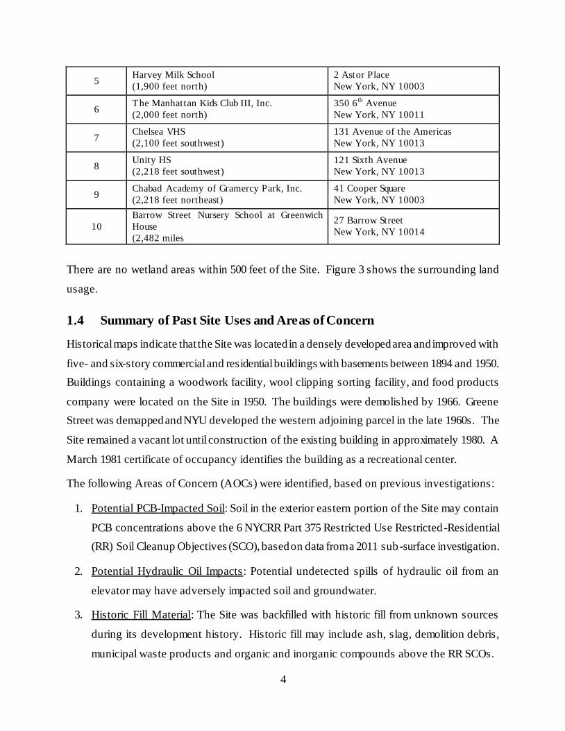
Sensitive receptors (e.g., schools and daycare centers) within a half mile of the Site are listed in
the following table:
Number Name
(Approximate distance from Site) Address
1 University Plaza Nursery School (60 feet
west)
110 Bleecker Street, New York, NY
10012
2 WSV Creative Steps Playgroup
(530 feet north)
4 Washington Square Village North
New York, NY 10012
3 St. Anthony’s School
(1,320 feet southeast)
80 Macdougal Street
New York, NY 10012
4 The Downing Street Playgroup, Inc.
(1,160 feet northeast)
32 Carmine Street
New York, NY 10014
4
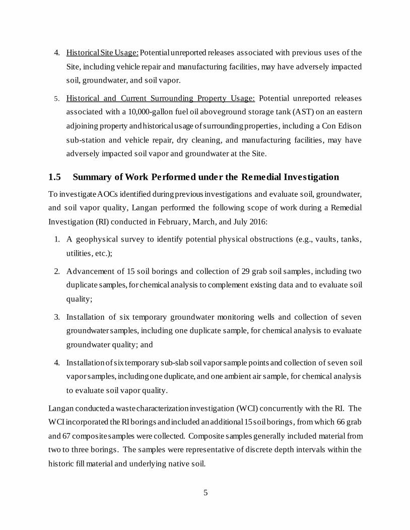
5 Harvey Milk School
(1,900 feet north)
2 Astor Place
New York, NY 10003
6 The Manhattan Kids Club III, Inc.
(2,000 feet north)
350 6th
Avenue
New York, NY 10011
7 Chelsea VHS
(2,100 feet southwest)
131 Avenue of the Americas
New York, NY 10013
8 Unity HS
(2,218 feet southwest)
121 Sixth Avenue
New York, NY 10013
9 Chabad Academy of Gramercy Park, Inc.
(2,218 feet northeast)
41 Cooper Square
New York, NY 10003
10
Barrow Street Nursery School at Greenwich
House
(2,482 miles
27 Barrow Street
New York, NY 10014
There are no wetland areas within 500 feet of the Site. Figure 3 shows the surrounding land
usage.
1.4 Summary of Past Site Uses and Areas of Concern
Historical maps indicate that the Site was located in a densely developed area and improved with
five- and six-story commercial and residential buildings with basements between 1894 and 1950.
Buildings containing a woodwork facility, wool clipping sorting facility, and food products
company were located on the Site in 1950. The buildings were demolished by 1966. Greene
Street was demapped and NYU developed the western adjoining parcel in the late 1960s. The
Site remained a vacant lot until construction of the existing building in approximately 1980. A
March 1981 certificate of occupancy identifies the building as a recreational center.
The following Areas of Concern (AOCs) were identified, based on previous investigations:
1. Potential PCB-Impacted Soil: Soil in the exterior eastern portion of the Site may contain
PCB concentrations above the 6 NYCRR Part 375 Restricted Use Restricted -Residential
(RR) Soil Cleanup Objectives (SCO), based on data from a 2011 sub-surface investigation.
2. Potential Hydraulic Oil Impacts: Potential undetected spills of hydraulic oil from an
elevator may have adversely impacted soil and groundwater.
3. Historic Fill Material: The Site was backfilled with historic fill from unknown sources
during its development history. Historic fill may include ash, slag, demolition debris,
municipal waste products and organic and inorganic compounds above the RR SCOs.
5
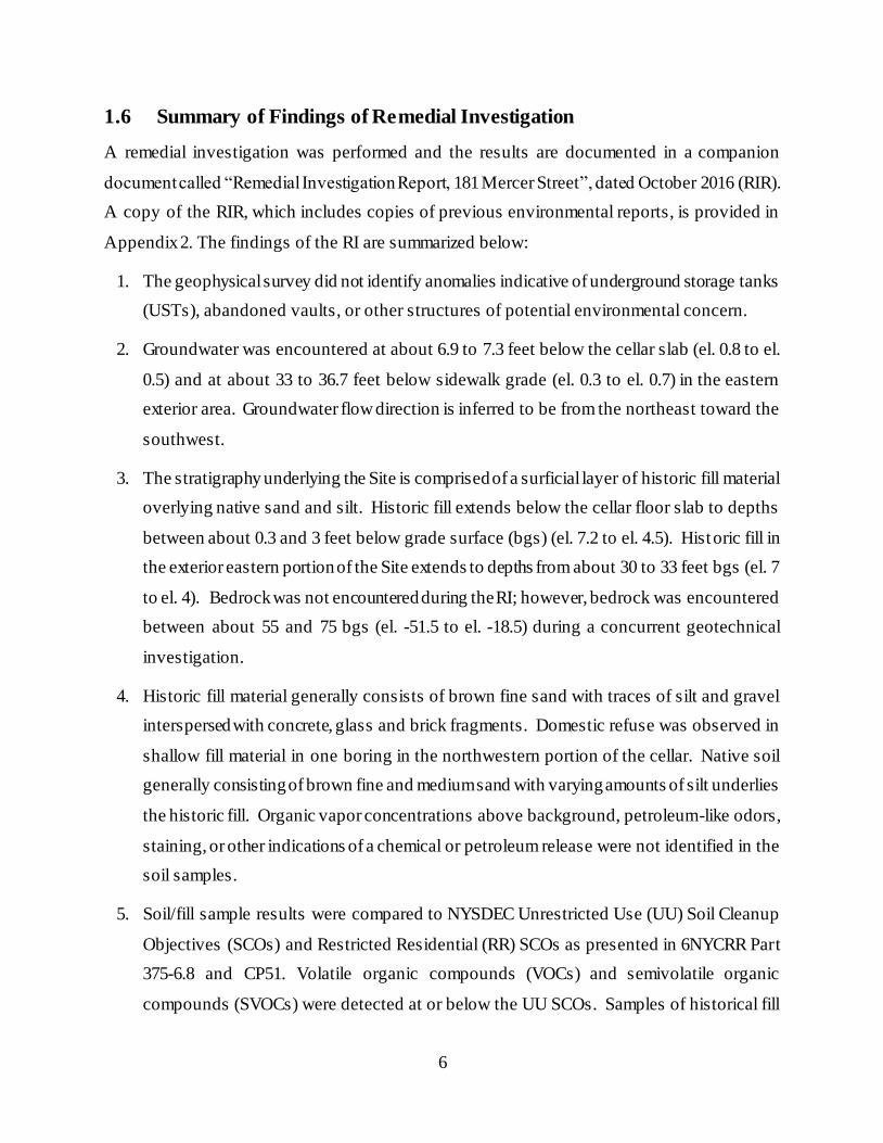
4. Historical Site Usage: Potential unreported releases associated with previous uses of the
Site, including vehicle repair and manufacturing facilities, may have adversely impacted
soil, groundwater, and soil vapor.
5. Historical and Current Surrounding Property Usage: Potential unreported releases
associated with a 10,000-gallon fuel oil aboveground storage tank (AST) on an eastern
adjoining property and historical usage of surrounding properties, including a Con Edison
sub-station and vehicle repair, dry cleaning, and manufacturing facilities, may have
adversely impacted soil vapor and groundwater at the Site.
1.5 Summary of Work Performed under the Remedial Investigation
To investigate AOCs identified during previous investigations and evaluate soil, groundwater,
and soil vapor quality, Langan performed the following scope of work during a Remedial
Investigation (RI) conducted in February, March, and July 2016:
1. A geophysical survey to identify potential physical obstructions (e.g., vaults, tanks,
utilities, etc.);
2. Advancement of 15 soil borings and collection of 29 grab soil samples, including two
duplicate samples, for chemical analysis to complement existing data and to evaluate soil
quality;
3. Installation of six temporary groundwater monitoring wells and collection of seven
groundwater samples, including one duplicate sample, for chemical analysis to evaluate
groundwater quality; and
4. Installation of six temporary sub-slab soil vapor sample points and collection of seven soil
vapor samples, including one duplicate, and one ambient air sample, for chemical analysis
to evaluate soil vapor quality.
Langan conducted a waste characterization investigation (WCI) concurrently with the RI. The
WCI incorporated the RI borings and included an additional 15 soil borings, from which 66 grab
and 67 composite samples were collected. Composite samples generally included material from
two to three borings. The samples were representative of discrete depth intervals within the
historic fill material and underlying native soil.
6
1.6 Summary of Findings of Remedial Investigation
A remedial investigation was performed and the results are documented in a companion
document called “Remedial Investigation Report, 181 Mercer Street”, dated October 2016 (RIR).
A copy of the RIR, which includes copies of previous environmental reports, is provided in
Appendix 2. The findings of the RI are summarized below:
1. The geophysical survey did not identify anomalies indicative of underground storage tanks
(USTs), abandoned vaults, or other structures of potential environmental concern.
2. Groundwater was encountered at about 6.9 to 7.3 feet below the cellar slab (el. 0.8 to el.
0.5) and at about 33 to 36.7 feet below sidewalk grade (el. 0.3 to el. 0.7) in the eastern
exterior area. Groundwater flow direction is inferred to be from the northeast toward the
southwest.
3. The stratigraphy underlying the Site is comprised of a surficial layer of historic fill material
overlying native sand and silt. Historic fill extends below the cellar floor slab to depths
between about 0.3 and 3 feet below grade surface (bgs) (el. 7.2 to el. 4.5). Historic fill in
the exterior eastern portion of the Site extends to depths from about 30 to 33 feet bgs (el. 7
to el. 4). Bedrock was not encountered during the RI; however, bedrock was encountered
between about 55 and 75 bgs (el. -51.5 to el. -18.5) during a concurrent geotechnical
investigation.
4. Historic fill material generally consists of brown fine sand with traces of silt and gravel
interspersed with concrete, glass and brick fragments. Domestic refuse was observed in
shallow fill material in one boring in the northwestern portion of the cellar. Native soil
generally consisting of brown fine and medium sand with varying amounts of silt underlies
the historic fill. Organic vapor concentrations above background, petroleum-like odors,
staining, or other indications of a chemical or petroleum release were not identified in the
soil samples.
5. Soil/fill sample results were compared to NYSDEC Unrestricted Use (UU) Soil Cleanup
Objectives (SCOs) and Restricted Residential (RR) SCOs as presented in 6NYCRR Part
375-6.8 and CP51. Volatile organic compounds (VOCs) and semivolatile organic
compounds (SVOCs) were detected at or below the UU SCOs. Samples of historical fill
7
material contained the pesticide 4,4’-DDT (max 0.03 mg/kg), and the polychlorinated
biphenyls (PCBs) Aroclor 1254 and Aroclor 1260 (total PCBs 1.11 mg/kg) were detected
at concentrations above the UU SCOs and below the RR SCOs. Four metals, including
lead (max 82.2 mg/kg), mercury (max 0.399 mg/kg), nickel (max 31.9 mg/kg) and zinc
(max 164 mg/kg), were detected at concentrations above the UU SCOs and below the RR
SCOs. Samples of native soil did not contain compounds above the UU SCOs.
6. Groundwater sample results were compared to 6NYCRR Part 703.5 Class GA groundwater
quality standards (GQS). One groundwater sample (MW21) contained chloroform (max 8
µg/l) and tetrachloroethylene (PCE) (max 6.3 µg/l) at concentrations above their respective
GQS. Chloroform is a common byproduct of the chlorination process for drinking water,
and PCE is a chlorinated solvent that was historically used in the commercial dry cleaning
process. Four dissolved metals (antimony, manganese, magnesium, and sodium) were
detected in at least one of the six wells at concentrations above the GQS. The presence of
manganese, magnesium, and sodium in each well indicates that the detections are likely
attributable to a regional groundwater condition. The antimony detection does not correlate
with detections in soil samples from the same boring (EB16) or with detections in other
groundwater samples. The occurrence may therefore reflect a localized condition.
7. Sub-slab soil vapor sample analytical results were evaluated based on the Decision
Matrices presented in the 2006 New York State Department of Health (NYSDOH)
Guidance for Evaluating Soil Vapor Intrusion in the State of New York and the 2013 and
2015 NYSDOH Ambient Air Guideline updates for trichloroethene (TCE) and
tetrachloroethene (PCE). Three of the seven compounds covered by the Decision Matrices
were detected: carbon tetrachloride, TCE, and PCE. The NYSDOH mitigation
recommendations include “no further action” to “monitor” and “mitigate”, based on the
detected soil vapor concentrations.
For more detailed results, consult the RIR. Based on an evaluation of the data and information
from the RIR and this RAWP, disposal of significant amounts of hazardous waste is not
suspected at this site.
8
2.0 Remedial Action Objectives
Based on the results of the RI, the following Remedial Action Objectives (RAOs) have been
identified for this Site:
Soil
Prevent direct contact with contaminated soil.
Prevent migration of contaminants that would result in groundwater or surface water
contamination.
Groundwater
Prevent direct exposure to contaminated groundwater.
Soil Vapor
Prevent exposure to contaminants in soil vapor.
Prevent migration of soil vapor into dwelling and other occupied structures.
9
3.0 Remedial Alternatives Analysis
The goal of the remedy selection process is to select a remedy that is protective of human health
and the environment taking into consideration the current, intended and reasonably anticipated
future use of the property. The remedy selection process begins by establishing RAOs for media
in which chemical constituents were found at concentrations greater than applicable standards,
criteria and guidance values (SCGs). Remedial alternatives are then developed and evaluated
based on the following ten criteria:
Protection of human health and the environment;
Compliance with SCGs;
Short-term effectiveness and impacts;
Long-term effectiveness and permanence;
Reduction of toxicity, mobility, or volume of contaminated material;
Implementability;
Cost effectiveness;
Community acceptance;
Land use; and
Sustainability.
As required, a Track 1 Unrestricted Use scenario is evaluated for the remedial action. The
following is a detailed description of the alternatives analyzed to address impacted media at the
Site:
Alternative 1:
Selection of NYSDEC 6NYCRR Part 375 Unrestricted Use (Track 1) SCOs .
Removal of all soil and fill exceeding Track 1 Unrestricted Use SCOs throughout the Site
and confirmation that Track 1 Unrestricted Use SCOs have been achieved with post -
excavation endpoint sampling. Based on the results of the Remedial Investigation, it is
expected that this alternative would be achieved by excavating the entire site footprint to
a minimum elevation of el. 1.0, which is about 6.5 feet below the existing sub-grade level
and about 34 feet below sidewalk grade. Historic fill material extends to a minimum
elevation of about el. 4.5, which is about 3.5 feet above the proposed sub -grade depth.
10
Based on the observations and results of the RI, the proposed excavation will extend to
depths required to achieve Unrestricted Use. If soil/fill containing analytes at
concentrations above Unrestricted Use SCOs is still present at the base of the excavation
after removal of all soil required for construction of the new building's sub-cellar level is
complete, additional excavation will be performed to ensure complete removal of soil/ fill
that does not meet Track 1 Unrestricted Use SCOs .
No Engineering or Institutional Controls are required for a Track 1 cleanup; however, as
part of development, a waterproofing membrane/vapor barrier will be installed beneath
the basement foundation and behind the foundation walls of the new building to prevent
potential exposures from soil vapor intrusion in the future.
Alternative 2:
Establishment of Site-Specific (Track 4) SCOs.
Removal of all soil and fill exceeding Track 4 Site-Specific SCOs throughout the Site and
confirmation that Track 4 Site-Specific SCOs have been achieved with post-excavation
endpoint sampling. Excavation for development purposes would take place to a depth of
approximately 6.5 feet below the existing sub-cellar slab and about 34 feet below existing
sidewalk grade. If soil/fill containing analytes at concentrations above Track 4 Site -
Specific SCOs is still present at the base of the excavation after removal of all soil
required for construction of the new building's sub-cellar level is complete, additional
excavation will be performed to ensure complete removal of soil/ fill that does not meet
Track 4 Site-Specific SCOs.
As part of development, a waterproofing membrane/vapor barrier will be installed
beneath the basement foundation and behind the foundation walls of the new building to
prevent potential exposures from soil vapor in the future.
Placement of a site cover system over the entire site as an engineering control (EC) to
prevent exposure to remaining soil and fill. The system will consist of a concrete
foundation slab within the building footprint.
Establishment of use restrictions (i.e., institutional controls [ICs]) including prohibitions
on the use of groundwater from the Site; prohibitions of restricted Site uses, such as
11
farming or vegetable gardening, to prevent future exposure pathways; and prohibition of
a higher level of land use without OER approval.
Establishment of an approved Site Management Plan (SMP) to ensure long -term
management of these Engineering and Institutional Controls including the performance of
periodic inspections and certification that the controls are performing as they were
intended. The SMP will note that the property owner and property owner’s successors
and assigns must comply with the approved SMP.
The property will continue to be registered with a Restrictive Declaration for Hazardous
Materials.
3.1 Threshold Criteria
Protection of Public Health and the Environment
This criterion is an evaluation of the remedy’s ability to protect public health and the
environment, and an assessment of how risks posed through each existing or potential pathway
of exposure are eliminated, reduced or controlled through removal, treatment, and
implementation of Engineering Controls or Institutional Controls. Protection of public health
and the environment must be achieved for all approved remedial actions.
Alternative 1
Alternative 1 would be protective of human health and the environ ment by removing
contaminated soil and fill exceeding Track 1 SCOs, thus eliminating potential for direct contact
with contaminated soil, and eliminating the risk of contamination leaching into groundwater,
once construction is complete. The construction measure to install a waterproofing
membrane/vapor barrier would mitigate potential risk from soil vapor intrusion from a potential
off-site source.
Alternative 2
Alternative 2 would achieve comparable protections of human health and the environment by
excavation and removal of most of the historic fill at the Site and by ensuring that remaining soil
and fill on-Site meets Track 4 Site-Specific SCO’s , as well as by placement of Institutional and
Engineering Controls, including a composite cover system. The site cover system would prevent
direct contact with any remaining on-Site soil and fill. Implementing Institutional Controls
including a Site Management Plan and continuing the Restrictive Declaration would ensure that
12
the cover system remains intact and protective of public health. Establishment of Track 4 Site-
Specific SCO’s would minimize the risk of contamination leaching into groundwater.
For both Alternatives, potential exposure to contaminated soil or groundwater during
construction would be minimized by implementing a Construction Health and Safety Plan
(CHASP), an approved Soil/Materials Management Plan (SMMP), and Community Air
Monitoring Plan (CAMP). Potential contact with contaminated groundwater would be prevented
as its use is prohibited by city laws and regulations. Potential future migration of off-Site soil
vapors into the new building would be prevented by installing a vapor barrier below the building
slab and outside foundations walls below grade.
3.2 Balancing Criteria
Compliance with Standards, Criteria and Guidance (SCGs)
This evaluation criterion assesses the ability of the alternative to achieve applicable standards,
criteria and guidance.
Alternative 1
Alternative 1 would achieve compliance with the remedial goals, chemical-specific SCGs and
RAOs for soil through removal of soil to achieve Track 1 Unrestricted Use SCOs and Protection
of Groundwater SCOs. Compliance with SCGs for soil vapor would also be achieved by
installing a waterproofing membrane/vapor barrier below the new building's basement slab and
continuing the vapor barrier outside of sub-grade foundation walls, as part of development.
Alternative 2
Alternative 2 would achieve compliance with the remedial goals, chemical-specific SCGs and
RAOs for soil through removal of soil to meet Track 4 Site-Specific SCOs. Compliance with
SCGs for soil vapor would also be achieved by installing a waterproofing membrane/vapor
barrier below the new building's basement slab and continuing the vapor barrier around sub-
grade foundation walls. An SMP would ensure that these controls remained protective for the
long term.
13
Health and safety measures contained in the CHASP and CAMP that comply with the applicable
SCGs shall be implemented during Site redevelopment under this RAWP. For both Alternatives,
focused attention to means and methods employed during the remedial action would ensure that
handling and management of contaminated material would be compliant with applicable SCGs.
These measures will protect on-site workers and the surrounding community from exposure to
site-related contaminants.
Short-Term Effectiveness and Impacts
This evaluation criterion assesses the effects of the alternative during the construction and
implementation phase until remedial action objectives are met. Under this criterion, alternatives
are evaluated with respect to their short term effects during the remedial action on public health
and the environment during implementation of the remedial action, including protection of the
community, protection of onsite workers and environmental impacts.
Alternatives 1 and 2 have similar short-term effectiveness during their respective
implementations, as each requires removal excavation of historic fill material. Both alternatives
would result in short-term dust generation impacts associated with excavation, handling, load out
of materials, and truck traffic. Attention to means and methods during the removal action,
including community air monitoring and appropriate truck routing, would minimize or negate the
overall impact of these activities.
An additional short-term adverse impact and risk to the community associated with both
remedial alternatives is increased truck traffic. About 2,300, 25-ton capacity truck-trips would
be necessary to transport fill and soil excavated during Site development for either Track 1 or
Track 4. Truck traffic will be routed on the most direct course using major thoroughfares where
possible and flag persons will be used to protect pedestrians at Site entrances and exits.
The potential adverse impact to the community, workers and the environment for both
alternatives would be minimized through implementation of control plans including a CHASP, a
CAMP and an SMMP, during all on-Site soil disturbance activities and would minimize the
release of contaminants into the environment. Both alternatives provide short -term effectiveness
in protecting the surrounding community by decreasing the risk of contact with on -Site
contaminants. Construction workers operating under appropriate management procedures and a
14
CHASP would be provided protection from on-Site contaminants by using personal protective
equipment, which would be worn consistent with the documented risks within the respective
work zones.
Long-Term Effectiveness and Permanence
This evaluation criterion addresses the results of a remedial action in terms of its permanence
and quantity/nature of waste or residual contamination remaining at the Site after response
objectives have been met, such as permanence of the remedial alternative, magnitude of
remaining contamination, adequacy of controls including the adequacy and suitability of ECs/ICs
that may be used to manage contaminant residuals that remain at the Site and assessment of
containment systems and ICs that are designed to eliminate exposures to contaminants, and long -
term reliability of ECs.
Alternative 1
The Track 1 remedy would achieve long-term effectiveness and permanence related to on-site
contamination by removing all impacted soil above Track 1 Unrestricted Use SCOs. Removal of
on-site contaminant sources will also minimize future potential groundwater contamination.
Installation of a waterproofing membrane/vapor barrier as a construction measure would prevent
potential future migration of soil vapors from a potential off-Site source into the new building.
Alternative 2
Alternative 2 would provide long-term effectiveness by:
1. Removing soil and fill with contaminant concentrations above Track 4 Site-
Specific SCOs;
2. Constructing a cover system across the Site;
3. Maintaining use restrictions;
4. Establishing an SMP to ensure long-term management of EC/ICs; and
5. Maintaining the hazardous materials Restrictive Declaration to memorialize these
controls for the long-term.
The SMP would provide long-term effectiveness of all EC/ICs by requiring periodic inspection
and certification that these controls and restrictions continue to be in place and functioning as
they were intended. The inspection and certification would document that protections designed
15
into the remedy provide continued protection.
Both alternatives would result in removal of soil contamination exceeding their respective SCOs,
which provides a permanent remedy over the long-term with respect to a remedy for
contaminated soil. This will also eliminate or minimize migration of any potential soil-related
contaminants to groundwater. Installation of a waterproofing membrane/vapor barrier as a
construction measure under both scenarios will mitigate potential sources of soil vapor intrusion.
Reduction of Toxicity, Mobility, or Volume of Contaminated Material
This evaluation criterion assesses the remedial alternative's use of remedial technologies that
permanently and significantly reduce toxicity, mobility, or volume of contaminants as their
principal element. The following is the hierarchy of source removal and control measures that
are to be used to remediate a Site, ranked from most preferable to least preferable: removal
and/or treatment, containment, elimination of exposure and treatment of source at the point of
exposure. It is preferred to use treatment or removal to eliminate contaminants at a Site, reduce
the total mass of toxic contaminants, cause irreversible reduction in contaminant mobility, or
reduce of total volume of contaminated media.
Alternative 1
Alternative 1 will permanently eliminate the toxicity, mobility, and volume of contaminated
material by removing all soil and fill exceeding Track 1 Unrestricted Use SCOs.
Alternative 2
Alternative 2 provides a similar reduction in toxicity, mobility, and volume of contaminated
material through the removal of all historic fill and the removal of any remaining soil exceeding
the Track 4 Site-Specific SCOs.
Implementability
This evaluation criterion addresses the technical and administrative feasibility of implementing
an alternative and the availability of various services and materials required during its
implementation, including technical feasibility of construction and operation, reliability of the
selected technology, ease of undertaking remedial action, monitoring considerations,
administrative feasibility (e.g. obtaining permits for remedial activities), and availability of
services and materials.
16
The techniques, materials and equipment to implement both remedial Alternatives 1 and 2 are
readily available and have been proven effective in remediating the contaminants associated with
the Site. They use standard materials and services that are well established technologies. Each
remedy is reliable. The remedial measures conform to the site development plans; hence, there
are no special difficulties associated with the activities proposed .
Cost Effectiveness
This evaluation criterion addresses the cost of alternatives, including capital costs (such as
construction costs, equipment costs, and disposal costs, engineering expenses) and site
management costs (costs incurred after remedial construction is complete) necessary to ensure
the continued effectiveness of a remedial action.
Since historic fill at the Site was found to extend to a depth of up to about 33 feet below sidewalk
grade during the RI, and the new building requires excavation of the entire Site to a minimum
depth of about 34 feet below sidewalk grade, the costs associated with both Alternative 1 and
Alternative 2 will likely be comparable. Costs associated with Alternative 1 could potentially be
higher than Alternative 2 if soil with analytes above Track 1 Unrestricted Use SCOs is
encountered below the excavation depth required for development. Additional costs would
include disposal of additional soil and import of clean soil for backfill. However, long-term costs
for Alternative 2 are likely higher than Alternative 1 based on implementation of a Site
Management Plan as part of Alternative 2.
The remedial plan would couple the remedial action with the redevelopment of the Site, lowering
total costs. The remedial plan will also consider the selection of the most appropriate disposal
facilities to reduce transportation and disposal costs during cleanup and redevelopment of the
Site.
Community Acceptance
This evaluation criterion addresses community opinion and support for the remedial action.
Observations here will be supplemented by public comment received on the RAWP.
Based on the overall goals of the remedial program and initial permitting associated with the
proposed Site development, no adverse community opinion is anticipated for either alternative.
17
This RAP will be subject to a public review under the VCP and will provide the opportunity for
detailed public input on the remedial alternatives, and the selected remedy. This public comment
will be considered by OER prior to approval of this plan. The Citizen Participation Plan for the
project is provided in Appendix 3. Observations here will be supplemented by public comment
received on the RAWP. Under both alternatives, the overall goals of the remedial program, to
protect public health and the environment and eliminate potential contaminant exposures, have
been broadly supported by citizens in NYC communities .
Land Use
This evaluation criterion addresses the proposed use of the property. This evaluation has
considered reasonably anticipated future uses of the Site and takes into account: current use and
historical and/or recent development patterns; applicable zoning laws and maps; NYS
Department of State’s Brownfield Opportunity Areas (BOA) pursuant to section 970-r of the
general municipal law; applicable land use plans; proximity to real property currently used for
residential use, and to commercial, industrial, agricultural, and/or recreational areas;
environmental justice impacts, Federal or State land use designations; population growth patterns
and projections; accessibility to existing infrastructure; proximity of the site to important cultural
resources and natural resources, potential vulnerability of groundwater to contamination that
might emanate from the site, proximity to flood plains, geography and geology; and current
Institutional Controls applicable to the site.
The current, intended, and reasonably anticipated future land use of the Site and its surroundings
are compatible with the selected remedy of soil remediation. The proposed future use of the Site
is an NYU-owned and operated facility consisting of a six-story podium that supports five, up to
23-story towers. The facility will contain a cellar and sub-cellar level under the podium. The
new facility will be used for student and faculty housing, commercial space, theaters, dining
areas, performing arts venues, athletic spaces, gymnasium zones and classrooms.
Following remediation, the Site will meet either Track 1 Unrestricted Use SCOs or Track 4 Site-
Specific SCOs, both of which are protective of public health and the environment for its planned
residential use. The proposed use is compliant with the 2012 Restrictive Declaration of Large-
Scale General Development for the NYU LSGD and is consistent with recent development
patterns. Both remediation alternatives are appropriate for the Site’s planned use.
18
The areas surrounding the Site are urban and consist of predominantly mixed residential,
commercial, and institutional buildings in zoning districts designated for commercial and
residential uses. The development would remediate an underutilized lot and provide a modern,
multiple-use recreational, classroom, and student/faculty residential facility. The proposed
development would clean up the property and make it safer, create new employment
opportunities, add living space, and provide economic and fiscal benefits to the city and state in
the form of economic revitalization and tax revenue.
Temporary short-term project impacts are being mitigated through Site management controls and
truck traffic controls during remediation activities.
The adjoining western portion of Lot 66 is occupied by University Village, a complex of three
high-rise apartment buildings. University Village is designated as a Historic Landmark by the
New York City Landmarks Preservation Commission. The Site is not in close proximity to other
important cultural resources, including federal- or state- historic or heritage Sites, Native
American religious Sites, natural resources, waterways, wildlife refuges, wetlands, or critical
habitats of endangered or threatened species. The Site is located in an urban area and not in
proximity to fish or wildlife.
Neither alternative would encroach on the landmarked University Village or result in potential
exposure pathways of contaminant migration affecting fish or wildlife. The remedial action is
also protective of groundwater natural resources. Municipal water supply wells are not present in
this part of City; therefore, groundwater from the Site cannot affect municipal water supply wells
or recharge areas. The Site does not lie in a Federal Emergency Management Agency (FEMA)-
designated flood plain. Both alternatives are equally protective of natural resources and cultural
resources. Improvements in the current environmental condition of the property achieved by
both alternatives are also consistent with the City’s goals for cleanup of contaminated land.
Sustainability of the Remedial Action
This criterion evaluates the overall sustainability of the remedial action alternatives and the
degree to which sustainable means are employed to implement the remedial action including
those that take into consideration NYC’s sustainability goals defined in PlaNYC: A Greener,
Greater New York. Sustainability goals may include: maximizing the recycling and reuse of
19
non-virgin materials; reducing the consumption of virgin and non-renewable resources;
minimizing energy consumption and greenhouse gas emissions; improving energy efficiency;
and promotion of the use of native vegetation and enhancing biodiversity during landscaping
associated with Site development.
While Alternative 2 would potentially result in lower energy usage based on reducing the volume
of material transported off site, both remedial alternatives are comparable with respect to the
opportunity to achieve sustainable remedial action. The remedial plan would take into
consideration the shortest trucking routes during off-site disposal of historic fill and other soil,
which would reduce greenhouse gas emissions and conserve energy used to fuel trucks. The
New York City Clean Soil Bank program is available for reuse of any clean native soils under
either alternative. A complete list of green remedial activities considered as part of the NYC
VCP is included in the Sustainability Statement, included as Appendix 4.
20
4.0 Remedial Action
4.1 Summary of Preferred Remedial Action
The preferred remedial action alternative is Alternative 1, the Track 1 remedial action. The
preferred remedial action achieves protection of public health and the environment for the
intended use of the property. The preferred remedial action will achieve all of the remedial action
objectives established for the project and addresses applicable SCGs. The preferred remedial
action is effective in both the short-term and long-term and reduces mobility, toxicity and
volume of contaminants. The preferred remedial action alternative is cost effective and
implementable and uses standards methods that are well established in the industry.
The proposed remedial action will consist of:
1. Preparation of a Community Protection Statement and performance of all required
NYC VCP Citizen Participation activities according to an approved Citizen
Participation Plan.
2. Performance of a Community Air Monitoring Program for particulates and volatile
organic carbon compounds.
3. Selection of NYSDEC Part 375 Unrestricted Use (Track 1) SCOs.
4. Site mobilization involving Site security setup, equipment mobilization, utility mark
outs and marking & staking excavation areas.
5. Completion of a Waste Characterization Study prior to excavation activities . A Waste
Characterization Study was completed during the RI and additional sampling will be
conducted as required for soil disposal facility approval. Waste characterization soil
samples were collected at a frequency of about one sample per 800 (approximate) cubic
yards of fill to be excavated. A Waste Characterization Report documenting sample
procedures, location and analytical results shall be submitted to OER as part of the
Remedial Action Report (RAR).
6. Excavation and removal of soil and fill exceeding Track 1 Unrestricted Use SCOs
during installation of the temporary support of excavation (SOE) system along the
northern, eastern and western perimeters of the Site. Soldier piles will be drilled to a
depth of about 48 to 50 feet below sidewalk grade (el. -15.0). The eastern and western
exterior portions of the Site will be excavated to the planned sub-grade elevation (el.
21
1.0, which is about 6.5 feet below the existing sub-grade level and about 34 feet below
sidewalk grade. The below-ground portions of the existing building will be demolished
during this phase. Approximately 22,000 cubic yards (CY) of soil will be removed
during the SOE phase.
7. Excavation and removal of soil and fill exceeding Track 1 Unrestricted Use SCOs
during bulk excavation in the footprint of the existing building. The footprint of the
former building will be excavated from the existing level (el. 7.5) to the sub-cellar
foundation slab elevation (el. 1.0), which is about 6.5 feet below the existing sub-grade
level and about 34 feet below sidewalk grade. Deeper excavation will occur in the
areas of the proposed swimming pool (el. -3.3 or about 37.5 feet below sidewalk
grade), the elevator pits (el. -4.7 or about 38.5 feet below sidewalk grade) and caissons
and caps (el. -1.5 and -5.0 or about 35.5 and 39 feet below sidewalk grade).
Approximately 16,000 CY of soil will be removed during this phase.
8. Screening of excavated soil fill during intrusive work for indications of contamination
by visual means, odor, and monitoring with a PID. Appropriate segregation of
excavated media on-Site.
9. Management of excavated materials including temporarily stockpiling and segregating
in accordance with defined material types and to prevent co-mingling of contaminated
material and non-contaminated materials.
10. Removal of underground storage tanks encountered during soil and fill removal.
Registration of tanks , reporting of petroleum spills associated with USTs, and
appropriate closure of these petroleum spills in compliance with applicable local, state
and federal laws and regulations is required for any decommissioned USTs .
11. Transportation and off-Site disposal of all soil and fill material at licensed or permitted
facilities in accordance with applicable laws and regulations for handling, transport, and
disposal, and this plan. Sampling and analysis of excavated media as required by
disposal facilities. Appropriate segregation of excavated media on-Site.
12. Collection and analysis of end-point samples to determine the performance of the
remedy with respect to attainment of Track 1 SCOs. If the initial end-point samples do
not meet Track 1 SCOs, additional excavation will be performed until confirmation of
22
Track 1 attainment is confirmed with supplemental end-point samples or a Track 4
remedy (i.e., Alternative 2) will be implemented in lieu of deeper excavation.
13. Import of materials to be used for backfill and cover in compliance with this plan and in
accordance with applicable laws and regulations.
14. Performance of all activities required for the remedial action, including acquisition of
required permits and attainment of pretreatment requirements, in compliance with
applicable laws and regulations .
15. Dewatering in compliance with city, state, and federal laws and regulations. Extracted
groundwater will either be containerized for off-site disposal at a licensed or permitted
facility or will be treated in accordance with a permit from the New York City
Department of Environmental Protection (NYCDEP) to meet pretreatment
requirements prior to discharge to the sewer system.
16. Implementation of storm-water pollution prevention measures in compliance with
applicable laws and regulations.
17. Submission of a Remedial Action Report (RAR) that describes the remedial activities,
certifies that the remedial requirements have been achieved, defines the Site
boundaries, and lists any changes from this RAWP.
If Track 1 Unrestricted Use SCOs are not achieved, the following construction elements
implemented as part of new development will constitute Engineering and Institutional Controls:
As part of development, construction of an engineered site cover system consisting of an
18-inch thick concrete foundation slab beneath all building areas.
As part of development, installation of a waterproofing membrane/vapor barrier system
consisting of vapor barrier beneath the building slab and outside of sub-grade foundation
sidewalls to mitigate soil vapor migration into the building. The system will consist of a
minimum 20-mil thick vapor barrier. The proposed waterproofing membrane/vapor
barrier will be manufactured by Grace Construction Products and will consist of
PrePrufe® 160 and 300R and Bituthene
® 30000/4000, or similar. All welds, seams and
penetrations will be properly sealed to prevent preferential pathways for vapor migration.
23
4.2 Soil Cleanup Objectives and Soil/ Fill Management
Track 1 SCOs are proposed for this project and SCOs are defined in 6 NYCRR Part 375, Table
6.8(a) Track 1 Unrestricted Use. If Track 1 SCOs are not achieved, the Track 4 Restricted
Commercial SCOs, as defined in 6 NYCRR Part 375, Table 6.8(b) Restricted Commercial Use
will be met.
Soil and materials management on-Site and off-Site, including excavation, handling and
disposal, will be conducted in accordance with the Soil/Materials Management Plan in Appendix
4. Discrete contaminant sources (such as hotspots) identified during the remedial action will be
identified by GPS or surveyed. This information will be provided in the Remedial Action Report.
Soil/Fill Excavation and Removal
The location of planned excavations is shown on Figure 4. Soil and fill removal will occur
during two construction phases. During the first phase, an SOE system consisting of drilled
soldier piles with lagging and tie backs will be installed along the northern, eastern, and western
perimeter of the Site. The soldier piles will be drilled to a depth of about 48 to 50 feet below
sidewalk grade (i.e., about el. -15). Following SOE installation, the exterior portions of the Site
will be excavated to the foundation construction depth, which is about 33 to 35 feet below
sidewalk grade (el. 1.0). The total quantity of soil and fill expected to be excavated and disposed
off-Site during this construction phase is about 33,000 tons.
During the foundation construction phase, the area in the footprint of the existing building will
be excavated to the foundation construction depth, which is about 6.5 feet below the current sub-
grade. Deeper excavation will occur in the areas of the proposed swimming pool (el. -3.3 or
about 37.5 feet below sidewalk grade), the elevator pits (el. -4.7 or about 38.5 feet below
sidewalk grade) and caissons and caps (el. -1.5 and -5.0, or about 35.5 and 39 feet below
sidewalk grade). The total quantity of soil and fill expected to be excavated and disposed off-
Site during this construction phase is about 24,000 tons.
For each disposal facility to be used, a letter from the developer/QEP to the receiving facility
requesting approval for disposal and a letter back to the developer/QEP providing approval for
disposal will be submitted to OER prior to any transport and disposal of soil at a facility.
24
Disposal facilities will be reported to OER when they are identified and prior to the start of
remedial action.
Confirmation End-point Sampling
After removal of historic fill material and soil to the proposed development depth, end point
samples will be collected. In addition to the 12 samples of native soil that were collected during
the RI at the development depth, 6 end point samples will be collected from the base of the
excavation at locations to be determined by OER. To evaluate attainment of Track 1 SCOs,
samples will be analyzed for VOCs, SVOCs, pesticides, PCBs and metals according to analytical
methods described below. If the initial end-point samples do not meet Track 1 SCOs, additional
excavation will be performed until confirmation of Track 1 attainment is confirmed with
supplemental end-point samples or a Track 4 remedy (i.e., Alternative 2) will be implemented in
lieu of deeper excavation. An endpoint sampling diagram is included as Figure5.
End-Point Sample Analyses
End-point samples will be analyzed for compounds and elements as described below utilizing the
following methodology:
Volatile organic compounds by EPA Method 8260;
Semi-volatile organic compounds by EPA Method 8270;
Target Analyte List metals; and
Pesticides/PCBs by EPA Method 8081/8082.
New York State ELAP certified labs will be used for all end-point sample analyses. Labs
performing end-point sample analyses will be reported in the RAR. The RAR will provide a
tabular and map summary of all end-point sample results and will include all data including non-
detects and applicable standards and/or guidance values.
Quality Assurance/Quality Control
The fundamental quality assurance (QA) objective with respect to accuracy, precision, and
sensitivity of analysis for laboratory analytical data is to achieve the QC acceptance of the
analytical protocol. The accuracy, precision and completeness requirements will be addressed by
the laboratory for all data generated.
25
One blind duplicate sample for every 20 samples collected will be submitted to the approved
laboratory for analysis of the same parameters. Trip blanks will be used whenever samples are
transported to the laboratory for analysis of VOCs. One trip blank will be submitted to the
laboratory with each shipment of soil samples. Trip blanks will not be used for samples to be
analyzed for metals, SVOCs or pesticides.
Samples will be appropriately packaged, placed in coolers and shipped via overnight courier or
delivered directly to the analytical laboratory by field personnel. Samples will be containerized
in appropriate laboratory provided glassware and shipped in plastic coolers. Samples will be
preserved through the use of ice or “cold-packs” to maintain a temperature of 4oC.
Dedicated disposable sampling materials will be used for the collection endpoint samples,
eliminating the need to prepare field equipment (rinsate) blanks. If non-disposable equipment is
used, (stainless steel scoop, etc.) field rinsate blanks will be prepared at the rate of one for every
20 samples collected. Decontamination of non-dedicated sampling equipment will consist of:
Gently tap or scrape to remove adhered soil;
Rinse with tap water;
Wash with Alconox® detergent solution and scrub;
Rinse with tap water; and
Rinse with distilled or deionized water.
Field blanks will be prepared by pouring distilled or deionized water over decontaminated
equipment and collecting the water in laboratory provided containers.
Import of Soils
Import of soils onto the property will be performed in conformance with the Soil/Materials
Management Plan in Appendix 4. Imported soil will meet Track 1 SCOs. The building
foundation will cover the excavation area. Placement of imported soil will be limited to a
landscaped area above the western 12-foot extension of the cellar. Reuse of soil that meets the
Track 1 SCOs, if required, will be allowed given there are no observable indications of
contamination (e.g. petroleum staining and odor) and reuse complies with 6 NYCRR Part 360.
A map of soil backfill placement locations will be provided with the Remedial Action Report.
26
Reuse of Onsite Soils
Reuse of onsite soils already onsite will be performed in conformance with the Soil/Materials
Management Plan in Appendix 4. Soil reuse is not planned on this project.
4.3 Engineering Controls
The remedial action will achieve Track 1 Unrestricted Use SCOs and no Engineering Controls
are required. However, the following design elements will be incorporated into the project as part
of the development:
(1) Composite Cover System
(2) Waterproofing Membrane/Soil Vapor Barrier System
If Track 1 is not achieved, these elements will constitute Engineering Controls that will be
employed in the remedial action to address residual contamination remaining at the Site.
Composite Cover System
If Track 1 is not achieved, exposure to residual soil and fill will be prevented by an engineered,
site cover system. This cover system will be comprised of an approximately 18-inch thick
concrete building slab. The composite cover is shown on the attached architectural drawin gs
(Appendix 1). In the event that a landscaped area is constructed on residual Site soil or fill, it
will be capped with a minimum of two feet of fill meeting Track 1 SCOs and top soil or gravel
imported from an approved facility/source. Soil or fill will be imported to the Site in accordance
with the SMMP in Appendix 5. A proposed composite cover design drawing for the project is
provided as Figure 6.
Vapor Barrier System
As a precaution against potential infiltration of soil vapors into the sub-grade building, a
waterproofing membrane/vapor barrier will be installed between the concrete sub-cellar slab and
underlying sub-grade layer, extending along the external walls of the sub-cellar and cellar
portions of the structure from the base of the excavation to surface grade level. The vapor barrier
system will have a minimum thickness of 20 mils. As-built vapor barrier plans will be submitted
with the RAR. Proposed vapor barrier design diagrams and specifications for the types of
27
waterproofing and vapor barrier products to be installed for the project are included in Appendix
6.
4.4 Institutional Controls
A Track 1 remedial action is proposed and Institutional Controls are not required. If a Track 1
remedial action is not achieved, Institutional Controls (ICs) will be incorporated in this remedial
action to manage residual soil/fill and other media and render the Site protective of public health
and the environment. These ICs define the program to operate, maintain, inspect and certify the
performance of Engineering Controls and Institutional Controls on this property. Institutional
Controls would be implemented in accordance with a Site Management Plan included in the final
Remedial Action Report (RAR). Institutional Controls would be:
Continued registration of the Restrictive Declaration for the property. This RAWP
includes a description of all ECs and ICs and summarizes the requirements of the SMP,
which will note that the property owner and property owner’s successors and assigns
must comply with the approved SMP;
Submittal of a SMP in the RAR for approval by OER that provides procedures for
appropriate operation, maintenance, inspection, and certification of ECs and IC’s. SMP
will require that the property owner and property owner’s successors and assigns will
submit to OER a periodic written statement that certifies that: (1) controls employed at
the Site are unchanged from the previous certification or that any changes to the controls
were approved by OER; and, (2) nothing has occurred that impairs the ability of the
controls to protect public health and environment or that constitute a violation or failure
to comply with the SMP. OER retains the right to enter the Site in order to evaluate the
continued maintenance of any controls. This certification shall be submitted at a
frequency to be determine by OER in the SMP and will comply with RCNY §43-
1407(l)(3).
Vegetable gardens and farming on the Site are prohibited in contact with residual soil
materials;
Use of groundwater underlying the Site is prohibited without treatment rendering it safe
for its intended use;
28
All future activities on the Site that will disturb residual material must be conduc ted
pursuant to the soil management provisions in an approved SMP; and
The Site will be used for mixed residential, recreational, and institutional use and will not
be used for a higher level of use without prior approval by OER.
4.5 Site Management Plan
A Track 1 remedial action is proposed and Site Management is not required. If a Track 1
remedial action is not achieved, Site Management will be required and will be the last phase of
remediation. Site Management will begin with the approval of the Remedial Action Report and
issuance of the Notice of Completion (NOC) for the Remedial Action. The Site Management
Plan (SMP) describes appropriate methods and procedures to ensure implementation of all ECs
and ICs that are required by this RAWP. The Site Management Plan is submitted as part of the
RAR but will be written in a manner that allows its use as an independent document. Site
Management continues until terminated in writing by OER. The property owner is responsible
to ensure that all Site Management responsibilities defined in the Site Management Plan are
implemented.
4.6 Qualitative Human Health Exposure Assessment
The objective of the qualitative exposure assessment is to identify potential receptors and
pathways for human exposure to the contaminants of concern (COC) that are present at, or
migrating from, the Site. The identification of exposure pathways describes the route that the
COC takes to travel from the source to the receptor. An identified pathway indicates that the
potential for exposure exists; it does not imply that exposures actually occur.
Data and information reported in the Remedial Investigation Report (RIR) are sufficient to
complete a Qualitative Human Health Exposure Assessment (QHHEA) for this project. As part
of the VCP process, a QHHEA was performed to determine whether the Site poses an existing or
future health hazard to the Site’s exposed or potentially exposed population. The sampling data
from the RI were evaluated to determine whether there is any health risk under current and future
conditions by characterizing the exposure setting, identifying exposure pathways, and evaluating
contaminant fate and transport. This QHHEA was prepared in accordance with Appendix 4B and
29
Section 3.3 (b) 8 of the NYSDEC Draft DER-10 Technical Guidance for Site Investigation and
Remediation.
Known and Potential Contaminant Sources
Known and potential sources were identified during previous investigations at the Site and
include the AOCs that were evaluated during the RI. The AOCs for the Site are summarized
below:
1. Potential PCB-Impacted Soil: A 2011 sub-surface investigation indicated that soil in the
exterior eastern portion of the Site may contain PCBs above the Part 375 Restricted Use
Restricted-Residential (RR) SCOs.
2. Potential Hydraulic Oil Impacts: Potential undetected spills of hydraulic oil from an
elevator may have adversely impacted soil and groundwater.
3. Historic Fill Material: The Site was backfilled with historic fill material from unknown
sources during its development history. Historic fill may include ash, slag, demolition
debris, municipal waste products and organic and inorganic compounds above the RR
SCOs.
4. Historical Site Usage: Potential unreported releases associated with previous uses of the
Site, including vehicle repair and manufacturing facilities, may have adversely impacted
soil, groundwater, and soil vapor.
5. Historical and Current Surrounding Property Usage: Potential unreported releases
associated with a 10,000-gallon fuel oil AST on an eastern adjoining property and
historical usage of surrounding properties, including a Con Edison sub-station and vehicle
repair, dry cleaning, and manufacturing facilities, may have adversely impacted soil vapor
and groundwater at the Site.
Based on the results of the RIR, the contaminants of concern are:
Soil:
Part 375 analytes were not detected at concentrations above the RR SCOs. Multiple
metals (i.e., mercury, lead, zinc, and nickel) and one pesticide, 4,4’-DDT, were detected
at concentrations above the Part 375 Unrestricted Use (UU) SCOs in samples collected
from the upper 10 feet of historic fill material
30
Groundwater:
VOCs including chloroform and PCE were detected above their respective TOGS SGVs.
Dissolved metals including antimony, manganese, magnesium, and sodium, were
detected above the respective TOGS SGVs.
Soil Vapor:
TCE was detected in one sample at a concentration corresponding to recommendations
ranging from “No Further Action” to “Monitor” and “Mitigate”, according to the
NYSDOH Final Guidance on Soil Vapor Intrusion in the State of New York.
31
Nature, Extent, Fate and Transport of Contaminants
Soil and Fill Material
The information compiled during the RI and previous investigations indicated the presence of
historic fill material from surface grade to depths ranging from about 1 to 6 feet below the sub-
cellar floor slab and about 30 to 33 feet below sidewalk grade. The fill material generally
consists of brown fine sand with traces of silt and gravel interspersed with concrete, glass and
brick fragments. Laboratory analytical results from the RI did not identify Part 375 analytes at
concentrations above the RR SCOs. Multiple metals (i.e., mercury, lead, zinc, and nickel) and
one pesticide, 4,4’-DDT, were detected at concentrations above the Part 375 Unrestricted Use
SCOs in samples collected from the upper 10 feet of historic fill material. The detected metals
and 4,4’-DDT are likely indicative of background conditions in the historic fill.
Groundwater
Groundwater samples collected during the RI contained VOCs (chloroform and PCE) and
dissolved metals at concentrations above the TOGS SGVs. Chloroform is a common byproduct
of the chlorination process for drinking water, and PCE is a chlorinated solvent that was
historically used in the commercial dry cleaning process . An on-site source for chloroform or
PCE was not identified, based on the findings of the soil investigation and historical use of the
Site. The detected levels therefore likely reflect localized migration of contaminants from an
off-site source. The metals concentrations are distributed throughout groundwater at the Site and
are therefore likely associated with dissolved, naturally occurring mineral constituents from
regional soil or the quality of the historic fill material.
Soil Vapor
Soil vapor samples collected during the RI contained VOCs. TCE (max. 12 µg/m3) is a soil
vapor contaminant of concern. The source of the TCE in soil vapor appears to be off site, due to
the absence of impacts in soil or groundwater and the localized nature of the detection in a single
sample.
Receptor Populations
On-Site Receptors: The existing building currently vacant and undergoing demolition. Access
to the Site is restricted by a 10-foot high construction fence and a controlled construction
32
entrance. On-site receptors include demolition workers, NYU representatives, and visitors
granted access to the property by NYU. During construction, potential on-site receptors will
include construction workers, NYU representatives and sub-contractors, and NYU-authorized
visitors. If contamination remains under proposed future conditions, potential on-site receptors
would include NYU students, faculty, and personnel, adult and children building residents, and
visitors.
Off-Site Receptors: Potential off-site receptors within a 500 foot radius of the Site include adult
and child residents; commercial and construction workers; pedestrians; and trespassers based on
the following land uses within 500 feet of the Site:
1. Commercial Businesses – There are street-level commercial businesses east of
Mercer Street, west of the adjoining residential building, and south of West Houston
Street. The businesses are expected to remain after completion of the proposed
development project.
2. Residential Buildings –There are currently NYU-owned residential high-rise
buildings located immediately west of the Site and north of the Site across Bleecker
Street. Mixed-use buildings with residential units are located east and south of the
Site across Mercer Street and West Houston Street. The surrounding residential uses
are expected to remain after completion of the development project .
3. Pedestrians and Cyclists – Pedestrian traffic (including cyclists) is currently possible
on Mercer Street to the east, West Houston Street to the south, Bleecker Street to the
north, and the Greene Street Walkway to the west. The traffic will continue after the
development project is complete.
4. Schools – According to NYCityMap (i.e., New York City GIS), there are no schools
within 500 feet of the Site.
Potential Routes of Exposure
Three potential primary routes exist by which chemicals can enter the body: ingestion,
inhalation, and dermal absorption. Exposure can occur based on the following potential
exposure pathways:
• Ingestion of groundwater or fill/soil;
• Inhalation of vapors or particulates; and
33
• Dermal absorption of groundwater or fill/soil.
Potential Exposure Points
Current Conditions: The area within the footprint of the existing building is currently capped
with an approximately five-inch thick concrete sub-cellar slab, and there are no potential
exposure pathways from ingestion, inhalation, or dermal absorption of soil/fill in that area. The
eastern exterior portion of the Site is currently being used as a construction staging area for site
demolition. The concrete pavement has been removed and historic fill is exposed in the
southeastern corner of the Site. Potential exposure pathways to construction workers in that area
include inhalation of vapors or particulates, ingestion of fill/soil, and dermal absorption of
fill/soil. Soil disturbance in the exposed area is limited to vehicle and foot traffic; excavation or
other earthwork is not occurring during the demolition phase of work. Site access is restricted to
construction workers and NYU-authorized personnel, and potential exposure to the general
public is therefore restricted.
Groundwater is not exposed at the site. The site is served by the public water supply and
groundwater is not used at the site for potable supply and there is no potential for exposure.
Potential soil vapor accumulation may occur underneath the sub-cellar floor slab. Potential
exposure to soil vapor is limited due to restricted site access during demolition and forthcoming
construction activities.
Construction/ Remediation Conditions: During the remedial action, onsite workers will come
into direct contact with surface and subsurface soil as a result of on-Site construction and
excavation. On-Site construction workers potentially could ingest, inhale or have dermal contact
with exposed impacted soil and fill. Similarly, off-Site receptors could be exposed to dust and
vapors from on-Site activities. Due to the depth of groundwater, direct contact with groundwater
will be limited to excavation within the swimming pool, elevator pit, and cais son areas. During
construction, on-Site and off-Site exposures to contaminated dust from on-Site will be addressed
through the Soil/Materials Management Plan, dust controls, and through the implementation of
the Community Air Monitoring Program and a Construction Health and Safety Plan.
Proposed Future Conditions: Under future remediated conditions, all soils in excess of Track 1
SCOs will be removed. The site will be fully capped, preventing potential direct exposure to soil
34
and groundwater remaining in place. A waterproofing membrane/soil vapor barrier will prevent
any potential exposure due to inhalation by preventing soil vapor intrusion. The Site is served by
the public water supply, and groundwater is not used at the site. There are no plausible off-site
pathways for oral, inhalation, or dermal exposure to contaminants derived from the Site.
Overall Human Health Exposure Assessment
Under current conditions, on-Site exposure pathways exist for those with access to the Site and
trespassers. There are potential complete exposure pathways that require mitigation during
implementation of the remedy. There are no complete exposure pathways under future
conditions after the site is developed. This assessment takes into consideration the reasonably
anticipated use of the Site, which includes residential, recreational, and educational use,
landscaped areas, a concrete sub-cellar floor slab, and a waterproofing membrane/vapor barrier.
During remedial construction, on-Site and off-Site exposures to dust from historic fill material
will be addressed through dust controls, and through the implementation of the Community Air
Monitoring Program, the Soil/Materials Management Plan, and a Construction Health and Safety
Plan. Potential post-construction use of groundwater is not considered an option because
groundwater in this area of New York City is not used as a potable water source. There are no
surface waters in close proximity to the Site that could be impacted or threatened.
35
5.0 Remedial Action Management
5.1 Project Organization and Oversight
Principal personnel who will participate in the remedial action include the following:
Stuart Knoop, P.G. – Project Manager (Langan)
Michael Burke, CHMM, LEED AP – Qualified Environmental Professional (QEP) for
the project and Senior Associate (Langan)
Jason Hayes, P.E. – Professional Engineer for the project and Senior Associate (Langan).
5.2 Site Security
Site access will be controlled by 24-hour security, construction fencing, and gated construction
entrances .
5.3 Work Hours
The hours for operation of cleanup will comply with the NYC Department of Buildings (DOB)
construction code requirements, the terms of the Restrictive Declaration, or according to specific
variances issued by the NYC DOB. The hours of operation will be conveyed to OER during the
pre-construction meeting.
5.4 Construction Health and Safety Plan
The Health and Safety Plan is included in Appendix 6. The Site Safety Coordinator for Langan
will be William Bohrer. Contractors working at the Site will designate their respective Site
Safety Coordinator. Remedial work performed under this RAWP will be in full compliance with
applicable health and safety laws and regulations, including Site and OSHA worker safety
requirements and HAZWOPER requirements. Confined space entry, if any, will comply with
OSHA requirements and industry standards and will address potential risks. The parties
performing the remedial construction work will ensure that performance of work is in
compliance with the HASP and applicable laws and regulations. The CHASP pertains to
remedial and invasive work performed at the Site until the issuance of the Notice of Completion.
36
All field personnel involved in remedial activities will participate in training required under 29
CFR 1910.120, such as 40-hour hazardous waste operator training and annual 8-hour refresher
training. The Site Safety Officer will be responsible for maintaining workers training records.
Personnel entering any exclusion zone will be trained in the provisions of the CHASP and will
comply with all requirements of 29 CFR 1910.120. Site-specific training will be provided to
field personnel. Additional safety training may be added depending on the tasks performed.
Emergency telephone numbers will be posted at the site location before any remedial work
begins. A safety meeting will be conducted before each shift begins. Topics to be discussed
include task hazards and protective measures (physical, chemical, environmental); emergency
procedures; PPE levels and other relevant safety topics. Meetings will be documented in a log
book or specific form.
An emergency contact sheet with names and phone numbers is included in the CHASP. That
document will define the specific project contacts for use in case of emergency.
5.5 Community Air Monitoring Plan
Real-time air monitoring for volatile organic compounds (VOCs) and particulate levels at the
perimeter of the exclusion zone or work area will be performed. Continuous monitoring will be
performed for all ground intrusive activities and during the handling of contaminated or
potentially contaminated media. Ground intrusive activities include, but are not limited to,
soil/waste excavation and handling, test pit excavation or trenching, and the installation of soil
borings or monitoring wells.
Periodic monitoring for VOCs will be performed during non-intrusive activities such as the
collection of soil and sediment samples or the collection of groundwater samples from existing
monitoring wells. Periodic monitoring during sample collection, for instance, will consist of
taking a reading upon arrival at a sample location, monitoring while opening a well cap or
overturning soil, monitoring during well bailing/purging, and taking a reading prior to leaving a
sample location. Depending upon the proximity of potentially exposed individuals, continuous
monitoring may be performed during sampling activities. Examples of such situations include
groundwater sampling at wells on the curb of a busy urban s treet, in the midst of a public park,
or adjacent to a school or residence. Exceedances of action levels observed during performance
37
of the Community Air Monitoring Plan (CAMP) will be reported to the OER Project Manager
and included in the Daily Report.
VOC Monitoring, Response Levels, and Actions
Volatile organic compounds (VOCs) will be monitored at the downwind perimeter of the
immediate work area (i.e., the exclusion zone) on a continuous basis during invasive work.
Upwind concentrations will be measured at the start of each workday and periodically thereafter
to establish background conditions. The monitoring work will be performed using equipment
appropriate to measure the types of contaminants known or suspected to be present. The
equipment will be calibrated at least daily for the contaminant(s) of concern or for an appropriate
surrogate. The equipment will be capable of calculating 15-minute running average
concentrations, which will be compared to the levels specified below.
• If the ambient air concentration of total organic vapors at the downwind perimeter of the
work area or exclusion zone exceeds 5 parts per million (ppm) above background for the
15-minute average, work activities will be temporarily halted and monitoring continued.
If the total organic vapor level readily decreases (per instantaneous readings) below 5
ppm over background, work activities will resume with continued monitoring.
• If total organic vapor levels at the downwind perimeter of the work area or exclusion
zone persist at levels in excess of 5 ppm over background but less than 25 ppm, work
activities will be halted, the source of vapors identified, corrective actions taken to abate
emissions, and monitoring continued. After these steps, work activities will resume
provided that the total organic vapor level 200 feet downwind of the exclusion zone or
half the distance to the nearest potential receptor or residential/commercial structure,
whichever is less - but in no case less than 20 feet, is below 5 ppm over background for
the 15-minute average.
• If the organic vapor level is above 25 ppm at the perimeter of the work area, activities
will be shutdown.
All 15-minute readings must be recorded and be available for OER personnel to review.
Instantaneous readings, if any, used for decision purposes will also be recorded.
38
Particulate Monitoring, Response Levels, and Actions
Particulate concentrations will be monitored continuously at the upwind and downwind
perimeters of the exclusion zone at temporary particulate monitoring stations. The particulate
monitoring will be performed using real-time monitoring equipment capable of measuring
particulate matter less than 10 micrometers in size (PM-10) and capable of integrating over a
period of 15 minutes (or less) for comparison to the airborne particulate action level. The
equipment will be equipped with an audible alarm to indicate exceedance of the action level. In
addition, fugitive dust migration should be visually assessed during all work activities.
• If the downwind PM-10 particulate level is 100 micrograms per cubic meter (mcg/m3)
greater than background (upwind perimeter) for the 15-minute period or if airborne dust
is observed leaving the work area, then dust suppression techniques will be employed.
Work will continue with dust suppression techniques provided that downwind PM-10
particulate levels do not exceed 150 mcg/m3 above the upwind level and provided that no
visible dust is migrating from the work area.
• If, after implementation of dust suppression techniques, downwind PM-10 particulate
levels are greater than 150 mcg/m3 above the upwind level, work will be stopped and a
re-evaluation of activities initiated. Work will resume provided that dust suppression
measures and other controls are successful in reducing the downwind PM-10 particulate
concentration to within 150 mcg/m3 of the upwind level and in preventing visible dust
migration.
All readings will be recorded and be available for OER personnel to review.
5.6 Agency Approvals
All permits or government approvals required for remedial construction have been or will be
obtained prior to the start of remedial construction. Approval of this RAWP by OER does not
constitute satisfaction of these requirements and will not be a substitute for any required permit.
39
5.7 Site Preparation
Pre-Construction Meeting
OER will be invited to attend the pre-construction meeting at the Site with all parties involved in
the remedial process prior to the start of remedial construction activities.
Mobilization
Mobilization will be conducted as necessary for each phase of work at the Site. Mobilization
includes field personnel orientation, equipment mobilization (including securing all sampling
equipment needed for the field investigation), marking/staking sampling locations and utility
mark-outs. Each field team member will attend an orientation meeting to become familiar with
the general operation of the Site, health and safety requirements, and field procedures.
Utility Marker Layouts, Easement Layouts
The presence of utilities and easements on the Site will be fully investigated prior to the
performance of invasive work such as excavation or drilling under this plan by using, at a
minimum, the One-Call System (811). Underground utilities may pose an electrocution,
explosion, or other hazard during excavation or drilling activities. All invasive activities will be
performed incompliance with applicable laws and regulations including NYC Building Code to
assure safety. Utility companies and other responsible authorities will be contacted to locate and
mark the locations, and a copy of the Mark-Out Ticket will be retained by the contractor prior to
the start of drilling, excavation or other invasive subsurface operations. Overhead utilities may
also be present within the anticipated work zones. Electrical hazards associated with drilling in
the vicinity of overhead utilities will be prevented by maintaining a safe distance between
overhead power lines and drill rig masts.
Proper safety and protective measures pertaining to utilities and easements, and compliance with
all laws and regulations will be employed during invasive and other work contemplated under
this RAWP. The integrity and safety of on-Site and off-Site structures will be maintained during
all invasive, excavation or other remedial activity performed under the RAWP.
40
Dewatering
Dewatering is anticipated during remediation and construction occurring in the proposed
swimming pool, elevator pit, and caisson areas. Dewatering will be completed in accordance
with a NYCDEP permit. As part of the permit process, additional groundwater samples will be
collected and be analyzed for NYCDEP dewatering parameters. All dewatering will be
conducted in accordance with NYCDEP regulations regarding discharge to the municipal sewer
(including appropriate groundwater sampling and permitting) and NYSDEC regulations
regarding groundwater discharge. There shall be no discharge of groundwater onto or into the
Site, unless it has been shown by sampling and laboratory analysis to meet the requirements of
the TOGS SGVs. A copy of the NYCDEP or NYSDEC sewer discharge permit will be included
in the PE-certified RAR submitted to OER.
Equipment and Material Staging
Equipment and materials will be stored and staged in a manner that complies with applicable
laws and regulations.
Stabilized Construction Entrance
Steps will be taken to ensure that trucks departing the site will not track soil, fill or debris off-
Site. Such actions may include use of cleaned asphalt or concrete pads or use of stone or other
aggregate-based egress paths between the truck inspection station and the property exit.
Measures will be taken to ensure that adjacent roadways will be kept clean of project related
soils, fill and debris.
Truck Inspection Station
An outbound-truck inspection station will be set up close to the Site exit. Before exiting the Site,
trucks will be required to stop at the truck inspection station and will be examined for evidence
of contaminated soil on the undercarriage, body, and wheels. Soil and debris will be removed.
Brooms, shovels and clean water will be utilized for the removal of soil from vehicles and
equipment, as necessary.
41
Extreme Storm Preparedness and Response Contingency Plan
Damage from flooding or storm surge can include dislocation of soil and stockpiled materials,
dislocation of site structures and construction materials and equipment, and dislocation of
support of excavation structures. Damage from wind during an extreme storm event can create
unsafe or unstable structures, damage safety structures and cause downed power lines creating
dangerous site conditions and loss of power. In the event of emergency conditions caused by an
extreme storm event, the enrollee will undertake the following steps for site preparedness prior to
the event and response after the event.
Storm Preparedness
Preparations in advance of an extreme storm event will include the following: containerized
hazardous materials and fuels will be removed from the property; loose materials will be secured
to prevent dislocation and blowing by wind or water; heavy equipment such as excavators and
generators will be removed from excavated areas, trenches and depressions on the property to
high ground or removed from the property; an inventory of the property with photographs will be
performed to establish conditions for the site and equipment prior to the event; stockpile covers
for soil and fill will be secured by adding weights such as sandbags for added security and worn
or ripped stockpile covers will be replaced with competent covers; stockpiled hazardous wastes
will be removed from the property; stormwater management systems will be inspected and
fortified, including, as necessary: clean and reposition silt fences, hay bales; clean storm sewer
filters and traps; and secure and protect pumps and hosing.
Storm Response
At the conclusion of an extreme storm event, as soon as it is safe to access the property, a
complete inspection of the property will be performed. A site inspection report will be submitted
to OER at the completion of site inspection and after the site security is assessed. Site conditions
will be compared to the inventory of site conditions and material performed prior to the storm
event and significant differences will be noted. Damage from s torm conditions that result in
acute public safety threats, such as downed power lines or imminent collapse of buildings,
structures or equipment will be reported to public safety authorities via appropriate means such
as calling 911. Petroleum spills will be reported to NYS DEC within 2 hours of identification
42
and consistent with State regulations. Emergency and spill conditions will also be reported to
OER. Public safety structures, such as construction security fences will be repaired promptly to
eliminate public safety threats. Debris will be collected and removed. Dewatering will be
performed in compliance with existing laws and regulations and consistent with emergency
notifications, if any, from proper authorities. Eroded areas of soil including unsafe slopes will be
stabilized and fortified. Dislocated materials will be collected and appropriately managed.
Support of excavation structure will be inspected and fortified as necessary. Impacted stockpiles
will be contained and damaged stockpile covers will be replaced. Stormwater control systems
and structures will be inspected and maintained as necessary. If soil or fill materials are
discharged off site to adjacent properties, property owners and OER will be notified and
corrective measure plan designed to remove and clean dislocated material will be submitted to
OER and implemented following approval by OER and granting of site access by the property
owner. Impacted offsite areas may require characterization based on site conditions, at the
discretion of OER. If onsite petroleum spills are identified, a qualified environmental
professional will determine the nature and extent of the spill and report to NYS DEC’s spill
hotline at DEC 800-457-7362 within statutory defined timelines . If the source of the spill is
ongoing and can be identified, it should be stopped if this can be done safely. Potential hazards
will be addressed immediately, consistent with guidance issued by NYS DEC.
Storm Response Reporting
A site inspection report will be submitted to OER at the completion of site inspection. An
inspection report established by OER is available on OER’s website (www.nyc.gov/oer) and will
be used for this purpose. Site conditions will be compared to the inventory of site conditions and
material performed prior to the storm event and significant differences will be noted. The site
inspection report will be sent to the OER project manager and will include the site name,
address, tax block and lot, site primary and alternate contact name and phone number. Damage
and soil release assessment will include: whether the project had stockpiles; whether stockpiles
were damaged; photographs of damage and notice of plan for repair; report of whether soil from
the site was dislocated and whether any of the soil left the site; estimates of the volume of soil
that left the site, nature of impact, and photographs; description of erosion damage; description
of equipment damage; description of damage to the remedial program or the construction
43
program, such as damage to the support of excavation; presence of onsite or offsite exposure
pathways caused by the storm; presence of petroleum or other spills and status of spill reporting
to NYS DEC; description of corrective actions; schedule for corrective actions. This report
should be completed and submitted to OER project manager with photographs within 24 hours of
the time of safe entry to the property after the storm event.
5.8 Traffic Control
Drivers of trucks leaving the Site with soil/fill will be instructed to proceed without stopping in
the vicinity of the Site to prevent neighborhood impacts. The planned route on local roads for
trucks leaving the site is shown on Figure 7.
5.9 Demobilization
Demobilization will include:
• As necessary, restoration of temporary access areas and areas that may have been
disturbed to accommodate support areas (e.g., staging areas, decontamination areas,
storage areas, temporary water management areas, and access area);
• Removal of sediment from erosion control measures and truck wash and disposal of
materials in accordance with applicable laws and regulations;
• Equipment decontamination, and;
• General refuse disposal.
Equipment will be decontaminated and demobilized at the completion of all field activities.
Investigation equipment and large equipment (e.g., soil excavators) will be washed at the truck
inspection station as necessary. In addition, all investigation and remediation derived waste will
be appropriately disposed.
5.10 Reporting and Record Keeping
Daily reports
Daily reports providing a general summary of activities for each day of active remedial work will
be emailed to the OER Project Manager by the end of the following business day. Those reports
will include:
44
• Project number and statement of the activities and an update of progress made and
locations of excavation and other remedial work performed;
• Quantities of material imported and exported from the Site;
• Status of on-Site soil/fill stockpiles;
• A summary of all citizen complaints, with relevant details (basis of complaint; actions
taken; etc.);
• A summary of CAMP results noting all excursions. CAMP data may be reported;
• Photograph of notable Site conditions and activities.
The frequency of the reporting period may be revised in consultation with OER project manager
based on planned project tasks. Daily email reports are not intended to be the primary mode of
communication for notification to OER of emergencies (accidents, spills), requests for changes
to the RAWP or other sensitive or time critical information. However, such information will be
included in the daily reports. Emergency conditions and changes to the RAWP will be
communicated directly to the OER project manager by personal communication. Daily reports
will be included as an Appendix in the Remedial Action Report.
Record Keeping and Photo Documentation
Job-site record keeping for all remedial work will be performed. These records will be
maintained on-Site during the project and will be available for inspection by OER staff.
Representative photographs will be taken of the Site prior to any remedial activities and during
major remedial activities to illustrate remedial program elements and contaminant source areas.
Photographs will be submitted at the completion of the project in the RAR in digital format (i.e.
jpeg files).
5.11 Complaint Management
All complaints from citizens will be promptly reported to OER. Complaints relating to the
cleanup will be addressed and outcomes will also be reported to OER in daily reports. Notices to
OER will include the nature of the complaint, the party providing the complaint, and the actions
taken to resolve any problems.
45
5.12 Deviations from the Remedial Action Work Plan
All changes to the RAWP will be reported to, and approved by, the OER Project Manager and
will be documented in daily reports and reported in the Remedial Action Report. The process to
be followed if there are any deviations from the RAWP will include a request for approval for
the change from OER noting the following:
• Reasons for deviating from the approved RAWP;
• Effect of the deviations on overall remedy; and
• Determination with basis that the remedial action with the deviation(s) is protective of
public health and the environment.
46
6.0 Remedial Action Report
A Remedial Action Report (RAR) will be submitted to OER following implementation of the
remedial action defined in this RAWP. The RAR will document that the remedial work required
under this RAWP has been completed and has been performed in compliance with this plan. The
RAR will include:
• Information required by this RAWP;
• Text description with thorough detail of all engineering and institutional controls (if
Track 1 remedial action is not achieved)
• As-built drawings for all constructed remedial elements ;
• Manifests for al soil or fill disposal;
• Photographic documentation of remedial work performed under this remedy;
• Site Management Plan (if Track 1 remedial action is not achieved);
• Description of any changes in the remedial action from the elements provided in this
RAWP and associated design documents;
• Tabular summary of all end point sampling results (including all soil test results from the
remedial investigation for soil that will remain on site) and all soil/fill waste
characterization results, QA/QC results for end-point sampling, and other sampling and
chemical analysis performed as part of the remedial action;
• Test results or other evidence demonstrating that remedial systems are functioning
properly;
• Account of the source area locations and characteristics of all soil or fill material
removed from the Site including a map showing the location of these excavations and
hotspots, tanks or other contaminant source areas;
• Full accounting of the disposal destination of all contaminated material removed from the
Site. Documentation associated with disposal of all material will include transportation
and disposal records, and letters approving receipt of the material;
• Account of the origin and required chemical quality testing for material imported onto the
Site;
• Continue registration of the property with Restrictive Declaration by the NYC
Department of Buildings (if Track 1 remedial action is not achieved);

47
• The RAWP and Remedial Investigation Report will be included as appendices to the
RAR;
• Reports and supporting material will be submitted in digital form and final PDF’s will
include bookmarks for each appendix.
48
Remedial Action Report Certification
I, Jason Hayes, am currently a registered professional engineer licensed by the State of New York. I performed professional engineering services and had primary direct responsibility for
implementation of the remedial program for the 181 Mercer Street site, site number 17CVCP040M. I certify to the following:
I have reviewed this document, to which my signature and seal are affixed.
Engineering Controls implemented during this remedial action were designed by me or a person under my direct supervision and achieve the goals established in the Remedial
Action Work Plan for this site.
The Engineering Controls constructed during this remedial action were professionally observed by me or by a person under my direct supervision and (1) are consistent with
the Engineering Control design established in the Remedial action Work Plan and (2) are accurately reflected in the text and drawings for as -built design reported in this Remedial Action Report.
The OER-approved Remedial Action Work Plan dated [date] and Stipulations in a letter dated [date] were implemented and that to the best of my knowledge all requirements in those documents have been substantively complied with. I certify that to the best of my
knowledge contaminated soil, fill, liquids or other material from the property were taken to facilities licensed to accept this material in full compliance with applicable laws and regulations.
Name
PE License Number
Signature
Date
PE Stamp
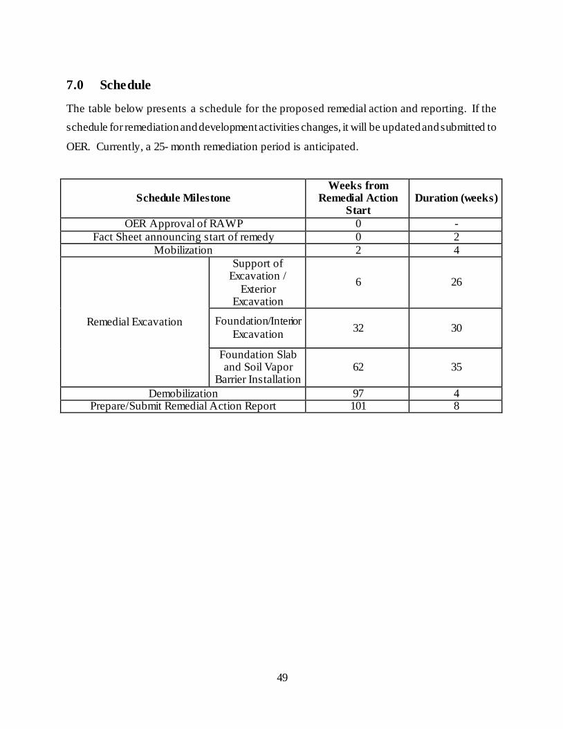
49
7.0 Schedule
The table below presents a schedule for the proposed remedial action and reporting. If the
schedule for remediation and development activities changes, it will be updated and submitted to
OER. Currently, a 25- month remediation period is anticipated.
Schedule Milestone Weeks from
Remedial Action Start
Duration (weeks)
OER Approval of RAWP 0 -
Fact Sheet announcing start of remedy 0 2
Mobilization 2 4
Remedial Excavation
Support of Excavation /
Exterior Excavation
6 26
Foundation/Interior
Excavation 32 30
Foundation Slab and Soil Vapor
Barrier Installation 62 35
Demobilization 97 4 Prepare/Submit Remedial Action Report 101 8

FIGURES
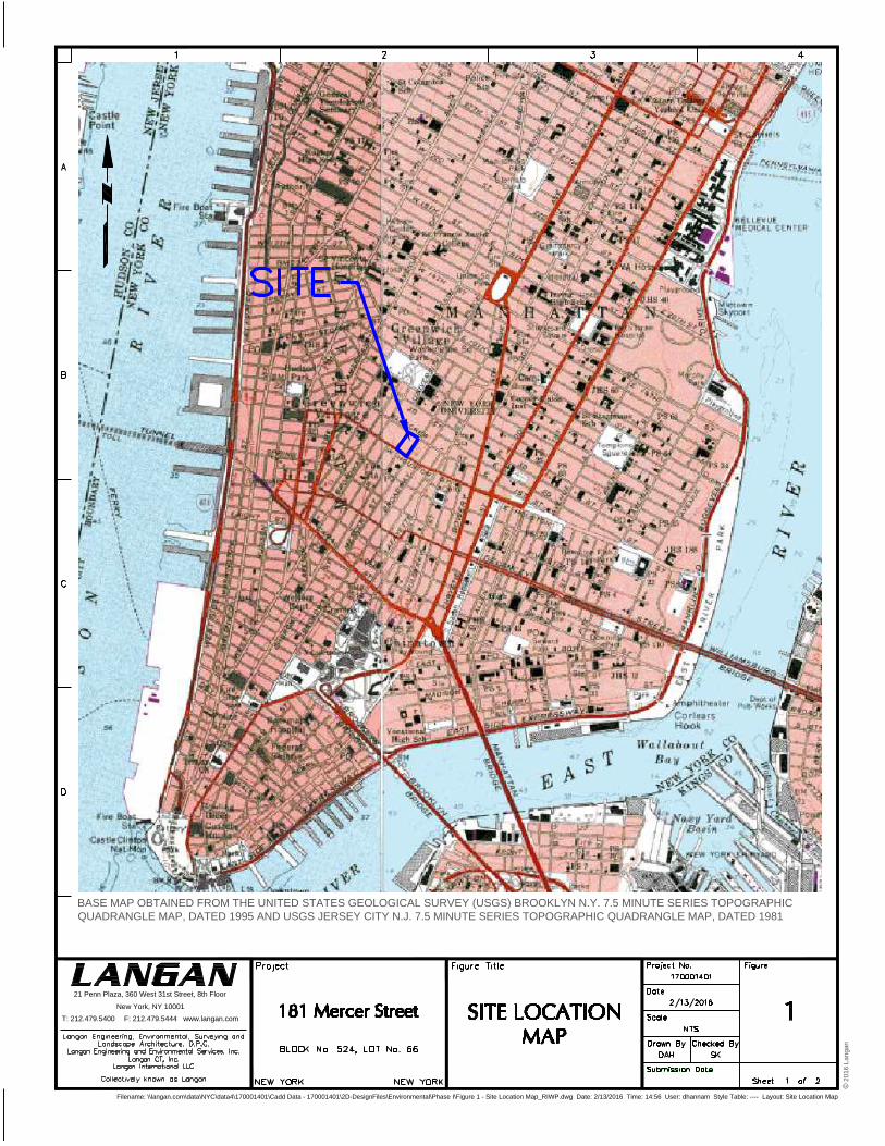
Filename: \\langan.com\data\NYC\data4\170001401\Cadd Data - 170001401\2D-DesignFiles\Environmental\Phase I\Figure 1 - Site Location Map_RIWP.dwg Date: 2/13/2016 Time: 14:56 User: dhannam Style Table: ---- Layout: Site Location Map
21 Penn Plaza, 360 West 31st Street, 8th Floor
New York, NY 10001
T: 212.479.5400 F: 212.479.5444 www.langan.com
BASE MAP OBTAINED FROM THE UNITED STATES GEOLOGICAL SURVEY (USGS) BROOKLYN N.Y. 7.5 MINUTE SERIES TOPOGRAPHIC
QUADRANGLE MAP, DATED 1995 AND USGS JERSEY CITY N.J. 7.5 MINUTE SERIES TOPOGRAPHIC QUADRANGLE MAP, DATED 1981
© 2
01
6 L
an
ga
n
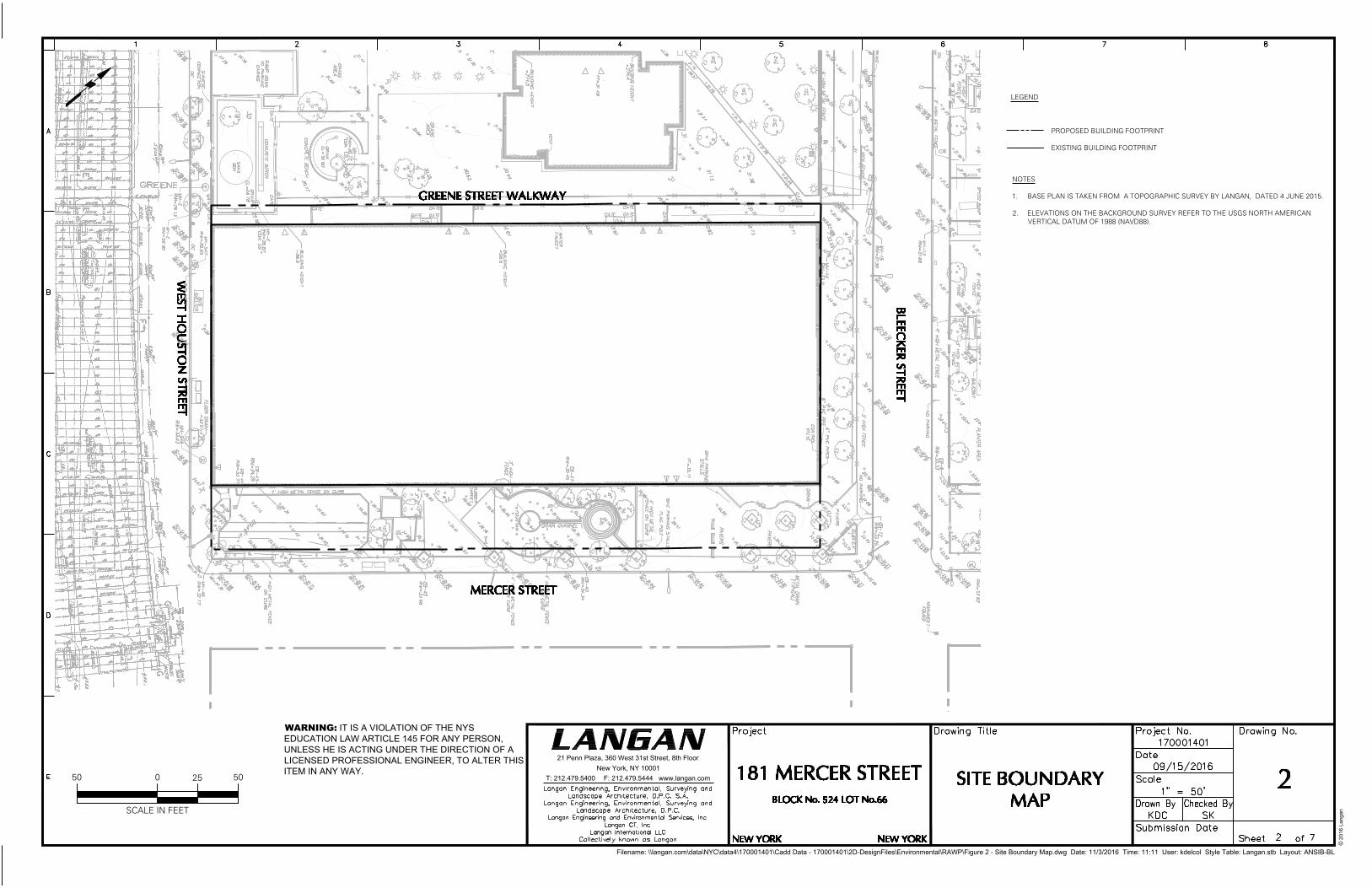
Filename: \\langan.com\data\NYC\data4\170001401\Cadd Data - 170001401\2D-DesignFiles\Environmental\RAWP\Figure 2 - Site Boundary Map.dwg Date: 11/3/2016 Time: 11:11 User: kdelcol Style Table: Langan.stb Layout: ANSIB-BL
WARNING: IT IS A VIOLATION OF THE NYS
EDUCATION LAW ARTICLE 145 FOR ANY PERSON,
UNLESS HE IS ACTING UNDER THE DIRECTION OF A
LICENSED PROFESSIONAL ENGINEER, TO ALTER THIS
ITEM IN ANY WAY.
21 Penn Plaza, 360 West 31st Street, 8th Floor
New York, NY 10001
T: 212.479.5400 F: 212.479.5444 www.langan.com
© 2
01
6 L
an
ga
n
LEGEND
PROPOSED BUILDING FOOTPRINT
EXISTING BUILDING FOOTPRINT
NOTES
1. BASE PLAN IS TAKEN FROM A TOPOGRAPHIC SURVEY BY LANGAN, DATED 4 JUNE 2015.
2. ELEVATIONS ON THE BACKGROUND SURVEY REFER TO THE USGS NORTH AMERICANVERTICAL DATUM OF 1988 (NAVD88).
SCALE IN FEET
050 25 50
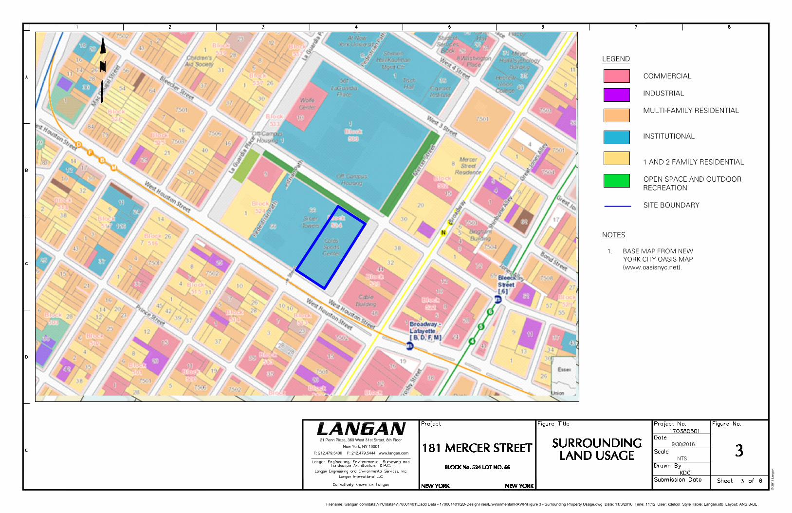
ELEV
ATO
REL
EVAT
OR
ELEV
ATO
R
LOT 5
LOT 7W
E
S
T
8
7
T
H
S
T
R
E
E
T
B
R
O
A
D
W
A
Y
W
E
S
T
E
N
D
A
V
E
N
U
E
Filename: \\langan.com\data\NYC\data4\170001401\Cadd Data - 170001401\2D-DesignFiles\Environmental\RAWP\Figure 3 - Surrounding Property Usage.dwg Date: 11/3/2016 Time: 11:12 User: kdelcol Style Table: Langan.stb Layout: ANSIB-BL
NTS
LEGEND
COMMERCIAL
INDUSTRIAL
MULTI-FAMILY RESIDENTIAL
INSTITUTIONAL
1 AND 2 FAMILY RESIDENTIAL
OPEN SPACE AND OUTDOOR RECREATION
SITE BOUNDARY
NOTES
1. BASE MAP FROM NEWYORK CITY OASIS MAP(www.oasisnyc.net).
21 Penn Plaza, 360 West 31st Street, 8th Floor
New York, NY 10001
T: 212.479.5400 F: 212.479.5444 www.langan.com
© 2
01
3 L
an
ga
n
9/30/2016
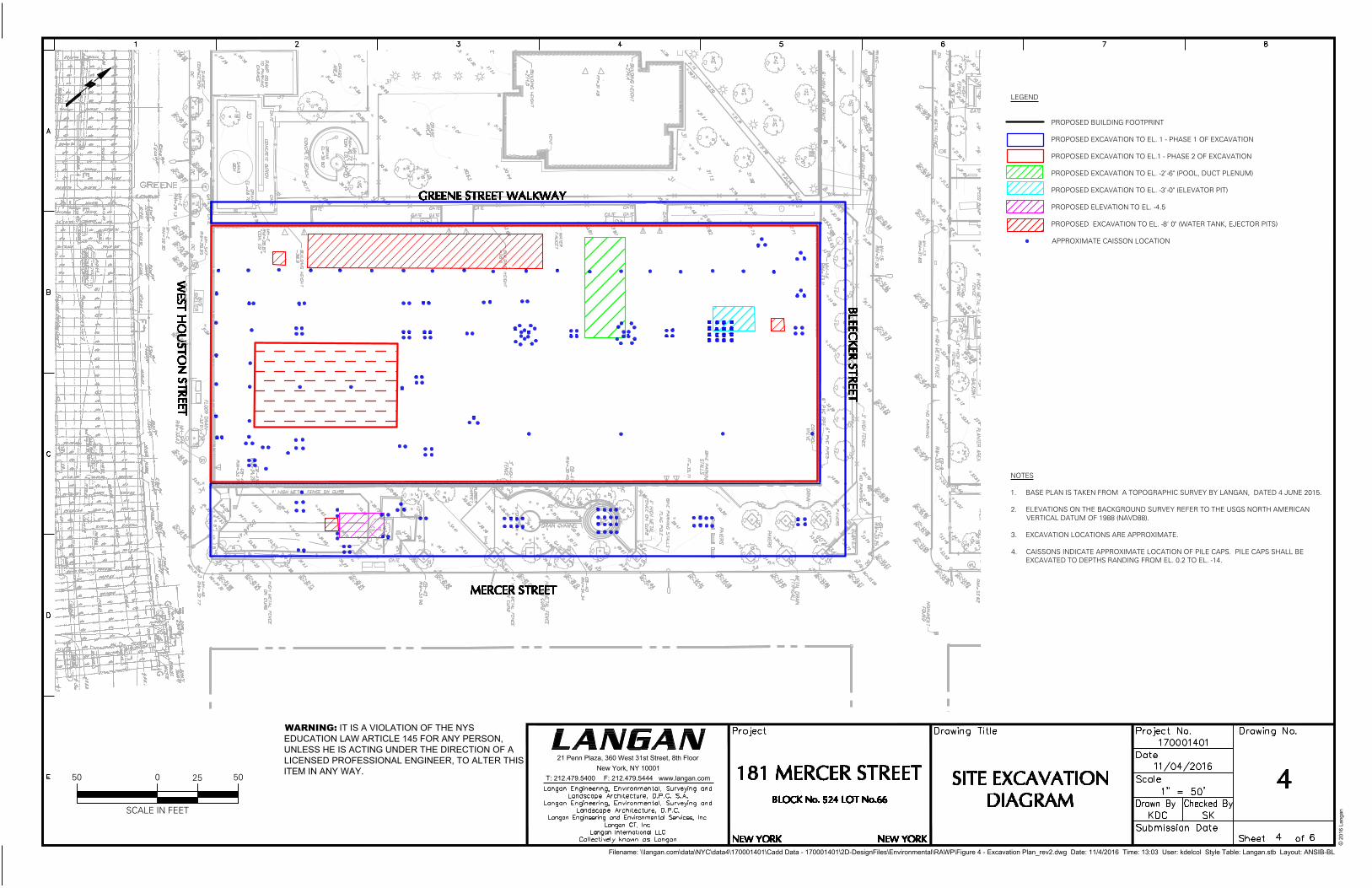
Filename: \\langan.com\data\NYC\data4\170001401\Cadd Data - 170001401\2D-DesignFiles\Environmental\RAWP\Figure 4 - Excavation Plan_rev2.dwg Date: 11/4/2016 Time: 13:03 User: kdelcol Style Table: Langan.stb Layout: ANSIB-BL
WARNING: IT IS A VIOLATION OF THE NYS
EDUCATION LAW ARTICLE 145 FOR ANY PERSON,
UNLESS HE IS ACTING UNDER THE DIRECTION OF A
LICENSED PROFESSIONAL ENGINEER, TO ALTER THIS
ITEM IN ANY WAY.
21 Penn Plaza, 360 West 31st Street, 8th Floor
New York, NY 10001
T: 212.479.5400 F: 212.479.5444 www.langan.com
© 2
01
6 L
an
ga
n
LEGEND
PROPOSED BUILDING FOOTPRINT
PROPOSED EXCAVATION TO EL. 1 - PHASE 1 OF EXCAVATION
PROPOSED EXCAVATION TO EL.1 - PHASE 2 OF EXCAVATION
PROPOSED EXCAVATION TO EL. -2'-6" (POOL, DUCT PLENUM)
PROPOSED EXCAVATION TO EL. -3'-0" (ELEVATOR PIT)
PROPOSED ELEVATION TO EL. -4.5
PROPOSED EXCAVATION TO EL. -8' 0" (WATER TANK, EJECTOR PITS)
APPROXIMATE CAISSON LOCATION
NOTES
1. BASE PLAN IS TAKEN FROM A TOPOGRAPHIC SURVEY BY LANGAN, DATED 4 JUNE 2015.
2. ELEVATIONS ON THE BACKGROUND SURVEY REFER TO THE USGS NORTH AMERICANVERTICAL DATUM OF 1988 (NAVD88).
3. EXCAVATION LOCATIONS ARE APPROXIMATE.
4. CAISSONS INDICATE APPROXIMATE LOCATION OF PILE CAPS. PILE CAPS SHALL BEEXCAVATED TO DEPTHS RANDING FROM EL. 0.2 TO EL. -14.
SCALE IN FEET
050 25 50
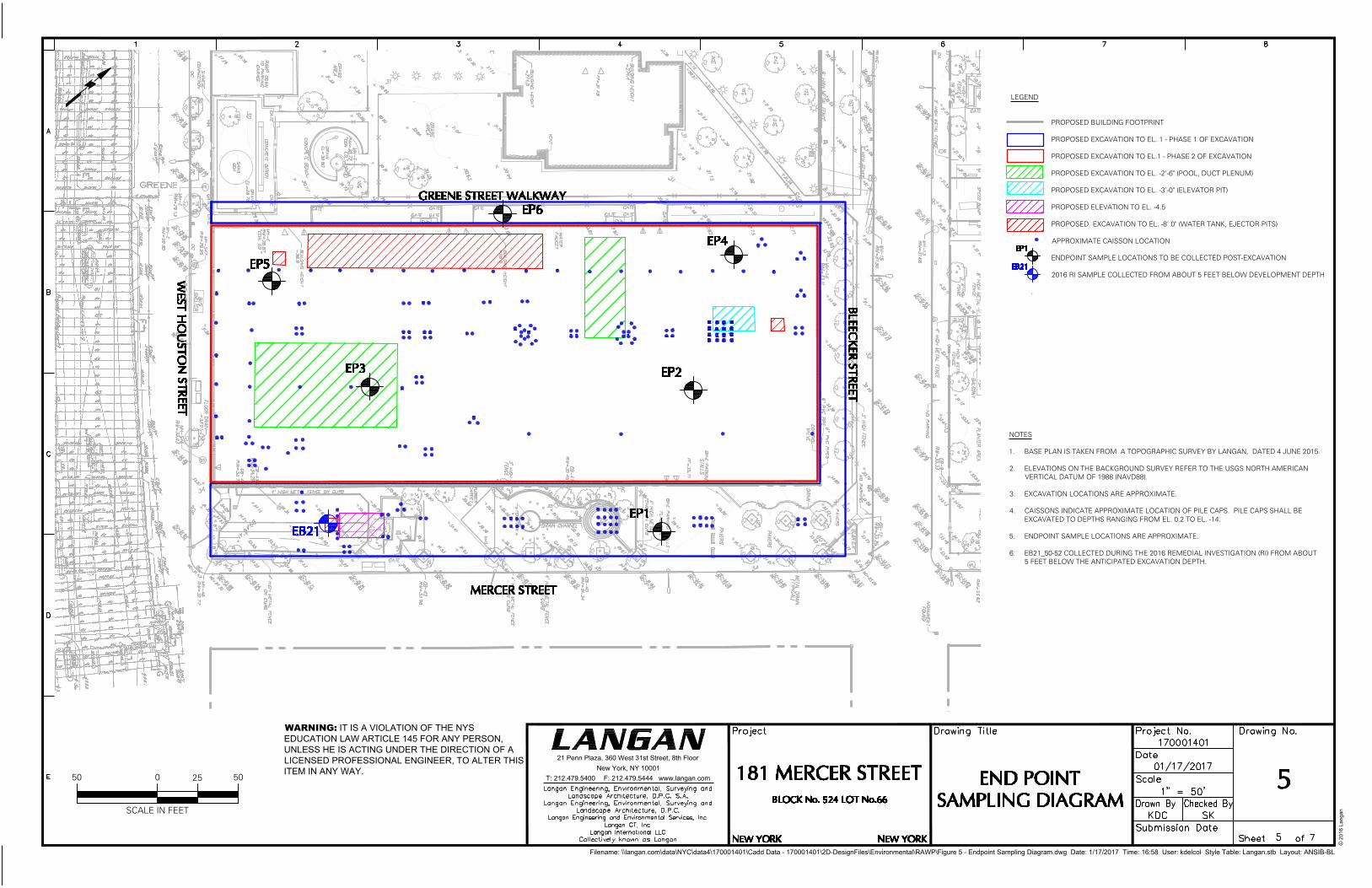
Filename: \\langan.com\data\NYC\data4\170001401\Cadd Data - 170001401\2D-DesignFiles\Environmental\RAWP\Figure 5 - Endpoint Sampling Diagram.dwg Date: 1/17/2017 Time: 16:58 User: kdelcol Style Table: Langan.stb Layout: ANSIB-BL
WARNING: IT IS A VIOLATION OF THE NYS
EDUCATION LAW ARTICLE 145 FOR ANY PERSON,
UNLESS HE IS ACTING UNDER THE DIRECTION OF A
LICENSED PROFESSIONAL ENGINEER, TO ALTER THIS
ITEM IN ANY WAY.
21 Penn Plaza, 360 West 31st Street, 8th Floor
New York, NY 10001
T: 212.479.5400 F: 212.479.5444 www.langan.com
© 2
01
6 L
an
ga
n
LEGEND
PROPOSED BUILDING FOOTPRINT
PROPOSED EXCAVATION TO EL. 1 - PHASE 1 OF EXCAVATION
PROPOSED EXCAVATION TO EL.1 - PHASE 2 OF EXCAVATION
PROPOSED EXCAVATION TO EL. -2'-6" (POOL, DUCT PLENUM)
PROPOSED EXCAVATION TO EL. -3'-0" (ELEVATOR PIT)
PROPOSED ELEVATION TO EL. -4.5
PROPOSED EXCAVATION TO EL. -8' 0" (WATER TANK, EJECTOR PITS)
APPROXIMATE CAISSON LOCATION
ENDPOINT SAMPLE LOCATIONS TO BE COLLECTED POST-EXCAVATION
2016 RI SAMPLE COLLECTED FROM ABOUT 5 FEET BELOW DEVELOPMENT DEPTH
.
NOTES
1. BASE PLAN IS TAKEN FROM A TOPOGRAPHIC SURVEY BY LANGAN, DATED 4 JUNE 2015.
2. ELEVATIONS ON THE BACKGROUND SURVEY REFER TO THE USGS NORTH AMERICANVERTICAL DATUM OF 1988 (NAVD88).
3. EXCAVATION LOCATIONS ARE APPROXIMATE.
4. CAISSONS INDICATE APPROXIMATE LOCATION OF PILE CAPS. PILE CAPS SHALL BEEXCAVATED TO DEPTHS RANGING FROM EL. 0.2 TO EL. -14.
5. ENDPOINT SAMPLE LOCATIONS ARE APPROXIMATE.
6. EB21_50-52 COLLECTED DURING THE 2016 REMEDIAL INVESTIGATION (RI) FROM ABOUT5 FEET BELOW THE ANTICIPATED EXCAVATION DEPTH.
SCALE IN FEET
050 25 50
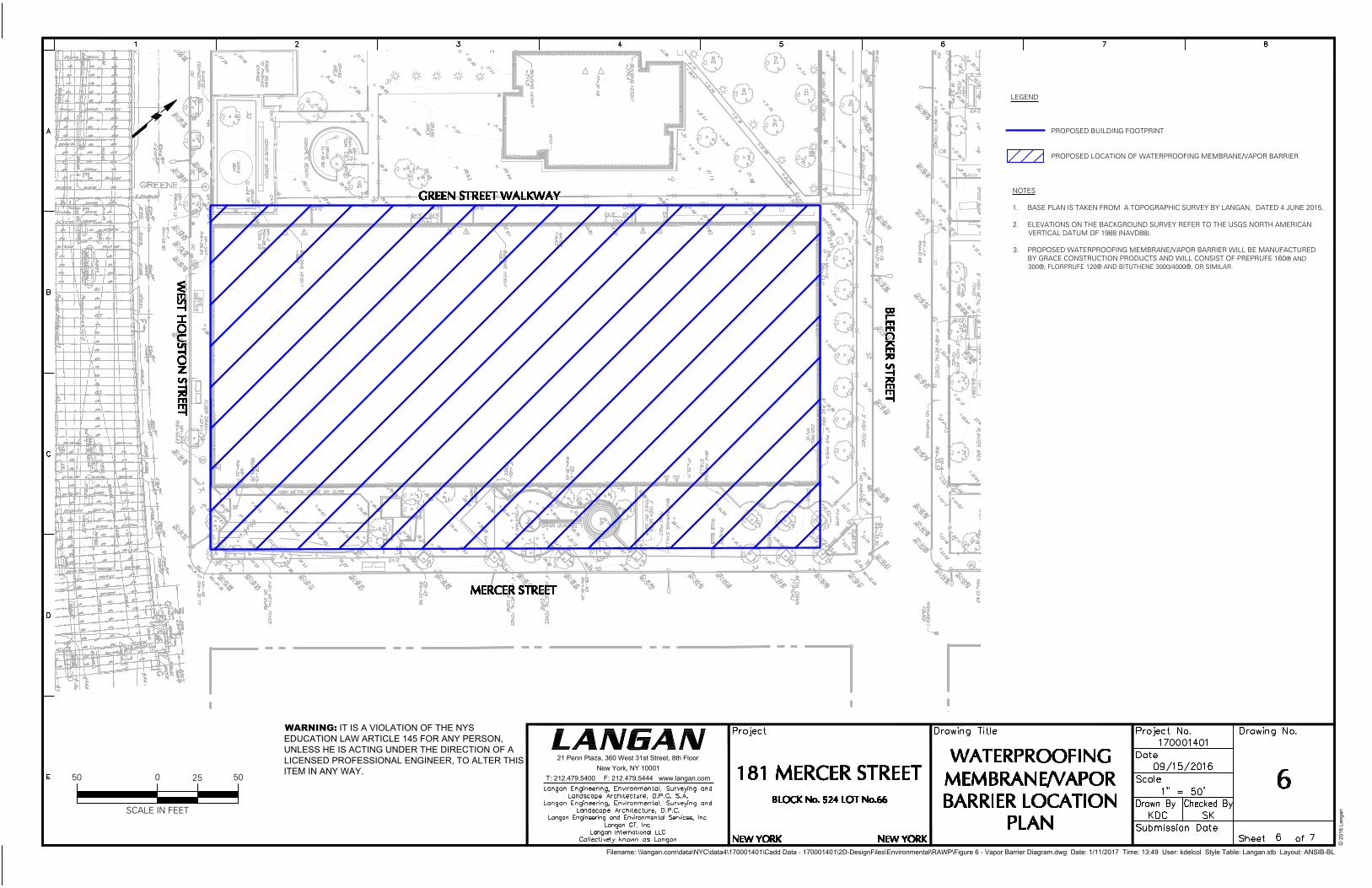
Filename: \\langan.com\data\NYC\data4\170001401\Cadd Data - 170001401\2D-DesignFiles\Environmental\RAWP\Figure 6 - Vapor Barrier Diagram.dwg Date: 1/11/2017 Time: 13:49 User: kdelcol Style Table: Langan.stb Layout: ANSIB-BL
WARNING: IT IS A VIOLATION OF THE NYS
EDUCATION LAW ARTICLE 145 FOR ANY PERSON,
UNLESS HE IS ACTING UNDER THE DIRECTION OF A
LICENSED PROFESSIONAL ENGINEER, TO ALTER THIS
ITEM IN ANY WAY.
21 Penn Plaza, 360 West 31st Street, 8th Floor
New York, NY 10001
T: 212.479.5400 F: 212.479.5444 www.langan.com
© 2
01
6 L
an
ga
n
LEGEND
PROPOSED BUILDING FOOTPRINT
PROPOSED LOCATION OF WATERPROOFING MEMBRANE/VAPOR BARRIER
NOTES
1. BASE PLAN IS TAKEN FROM A TOPOGRAPHIC SURVEY BY LANGAN, DATED 4 JUNE 2015.
2. ELEVATIONS ON THE BACKGROUND SURVEY REFER TO THE USGS NORTH AMERICANVERTICAL DATUM OF 1988 (NAVD88).
3. PROPOSED WATERPROOFING MEMBRANE/VAPOR BARRIER WILL BE MANUFACTUREDBY GRACE CONSTRUCTION PRODUCTS AND WILL CONSIST OF PREPRUFE 160® AND300®, FLORPRUFE 120® AND BITUTHENE 3000/4000®, OR SIMILAR.
SCALE IN FEET
050 25 50
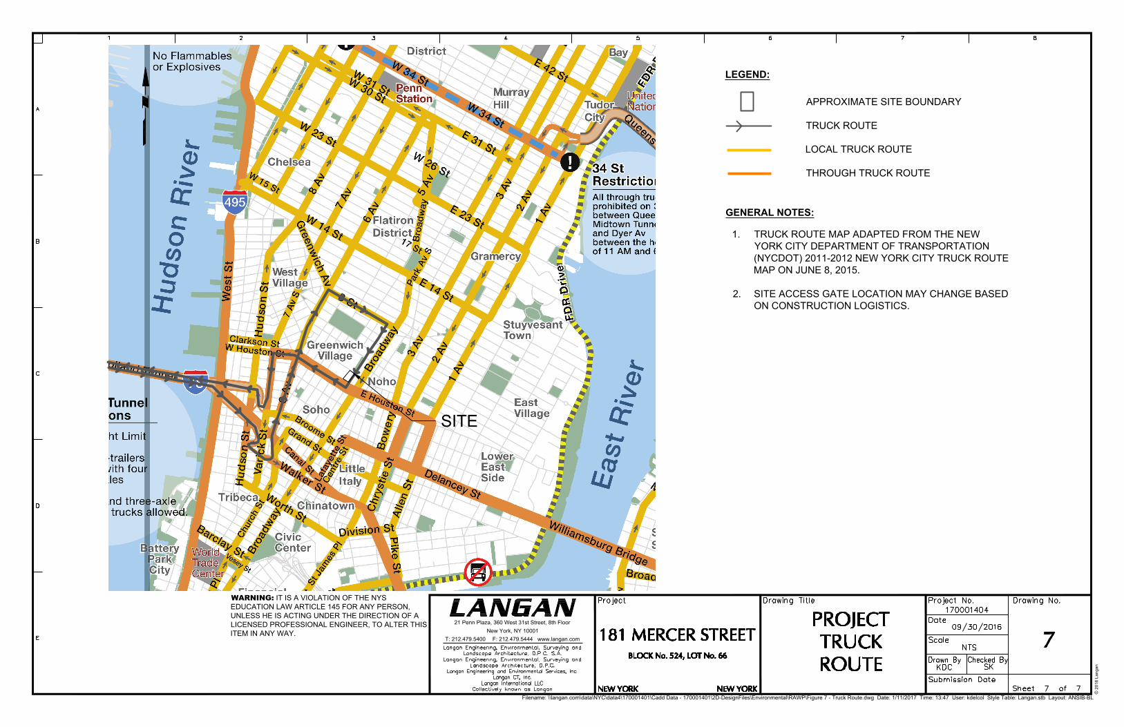
APPROXIMATE SITE BOUNDARY
TRUCK ROUTE
LOCAL TRUCK ROUTE
THROUGH TRUCK ROUTE
1. TRUCK ROUTE MAP ADAPTED FROM THE NEW
YORK CITY DEPARTMENT OF TRANSPORTATION
(NYCDOT) 2011-2012 NEW YORK CITY TRUCK ROUTE
MAP ON JUNE 8, 2015.
2. SITE ACCESS GATE LOCATION MAY CHANGE BASED
ON CONSTRUCTION LOGISTICS.
LEGEND:
GENERAL NOTES:
Filename: \\langan.com\data\NYC\data4\170001401\Cadd Data - 170001401\2D-DesignFiles\Environmental\RAWP\Figure 7 - Truck Route.dwg Date: 1/11/2017 Time: 13:47 User: kdelcol Style Table: Langan.stb Layout: ANSIB-BL
WARNING: IT IS A VIOLATION OF THE NYS
EDUCATION LAW ARTICLE 145 FOR ANY PERSON,
UNLESS HE IS ACTING UNDER THE DIRECTION OF A
LICENSED PROFESSIONAL ENGINEER, TO ALTER THIS
ITEM IN ANY WAY.
21 Penn Plaza, 360 West 31st Street, 8th Floor
New York, NY 10001
T: 212.479.5400 F: 212.479.5444 www.langan.com
© 2
01
6 L
an
ga
n
SITE

TABLES
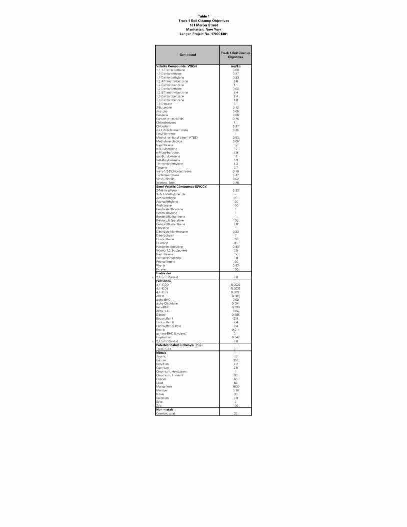
Table 1
Track 1 Soil Cleanup Objectives
181 Mercer Street
Manhattan, New York
Langan Project No. 170001401
CompoundTrack 1 Soil Cleanup
Objectives
Volatile Compounds (VOCs) mg/kg
1,1,1-Trichloroethane 0.68
1,1-Dichloroethane 0.27
1,1-Dichloroethylene 0.33
1,2,4-Trimethylbenzene 3.6
1,2-Dichlorobenzene 1.1
1,2-Dichloroethane 0.02
1,3,5-Trimethylbenzene 8.4
1,3-Dichlorobenzene 2.4
1,4-Dichlorobenzene 1.8
1,4-Dioxane 0.1
2-Butanone 0.12
Acetone 0.05
Benzene 0.06
Carbon tetrachloride 0.76
Chlorobenzene 1.1
Chloroform 0.37
cis-1,2-Dichloroethylene 0.25
Ethyl Benzene 1
Methyl tert-butyl ether (MTBE) 0.93
Methylene chloride 0.05
Naphthalene 12
n-Butylbenzene 12
n-Propylbenzene 3.9
sec-Butylbenzene 11
tert-Butylbenzene 5.9
Tetrachloroethylene 1.3
Toluene 0.7
trans-1,2-Dichloroethylene 0.19
Trichloroethylene 0.47
Vinyl Chloride 0.02
Xylenes, Total 0.26
Semi-Volatile Compounds (SVOCs)
2-Methylphenol 0.33
3- & 4-Methylphenols ~
Acenaphthene 20
Acenaphthylene 100
Anthracene 100
Benzo(a)anthracene 1
Benzo(a)pyrene 1
Benzo(b)fluoranthene 1
Benzo(g,h,i)perylene 100
Benzo(k)fluoranthene 0.8
Chrysene 1
Dibenzo(a,h)anthracene 0.33
Dibenzofuran 7
Fluoranthene 100
Fluorene 30
Hexachlorobenzene 0.33
Indeno(1,2,3-cd)pyrene 0.5
Naphthalene 12
Pentachlorophenol 0.8
Phenanthrene 100
Phenol 0.33
Pyrene 100
Herbicides
2,4,5-TP (Silvex) 3.8
Pesticides
4,4'-DDD 0.0033
4,4'-DDE 0.0033
4,4'-DDT 0.0033
Aldrin 0.005
alpha-BHC 0.02
alpha-Chlordane 0.094
beta-BHC 0.036
delta-BHC 0.04
Dieldrin 0.005
Endosulfan I 2.4
Endosulfan II 2.4
Endosulfan sulfate 2.4
Endrin 0.014
gamma-BHC (Lindane) 0.1
Heptachlor 0.042
2,4,5-TP (Silvex) 3.8
Polychlorinated Biphenyls (PCB)
Total PCBs 0.1
Metals
Arsenic 13
Barium 350
Beryllium 7.2
Cadmium 2.5
Chromium, Hexavalent 1
Chromium, Trivalent 30
Copper 50
Lead 63
Manganese 1600
Mercury 0.18
Nickel 30
Selenium 3.9
Silver 2
Zinc 109
Non-metals
Cyanide, total 27

APPENDICES

APPENDIX 1
Proposed Development Plans
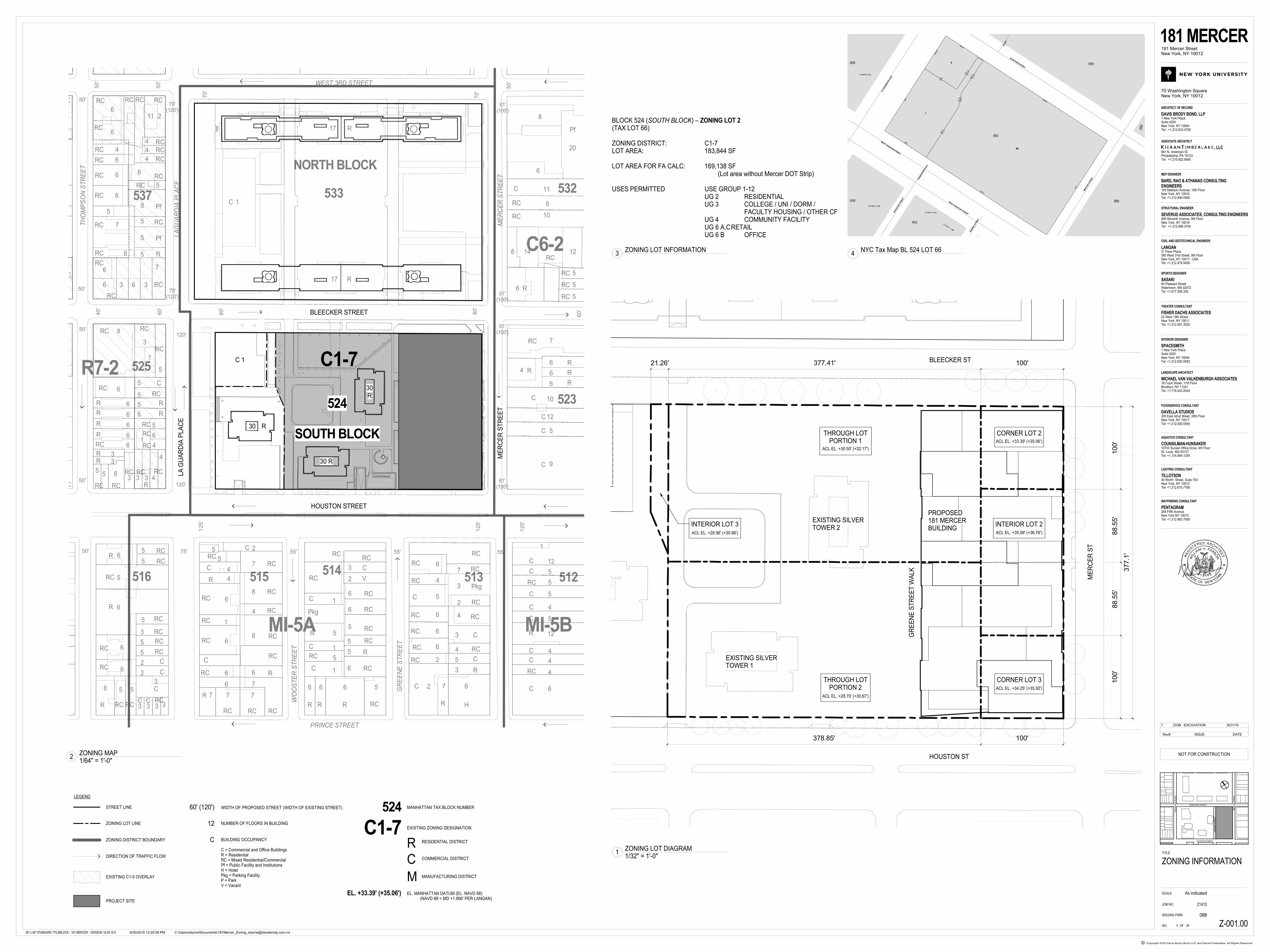
WEST 3RD STREET
LA
GU
AR
DIA
PL
AC
E
ME
RC
ER
ST
RE
ET
TH
OM
PS
ON
ST
RE
ET
PRINCE STREET
9
5
12
10
6
6
64
7
5
5
5
12148
6
10
8
11
20
8
6
13
211
4
4
4
6
5
8
7
5
5
5
6
6
4
6
6
6
5
7
6
6
6 3 36
5
1
3
8
6
6
6
6
6
6
33
55 6
3 3 3 4
4
4
6
5
1
5
5
5
5
5
5
5
3
3
2
2
5
5
3
333
556
6
6
6
5
65
5
4
4
6
1
6
6
6
7 7 7
6 6 6 5
6
5
5
5
6
6
2
3
1
5
1
5
1
6
4
5
6
6
6
2
2 7 6
3
5
4
3
4
2
3
7
12
5
1
5
5
4
5
12
4
4
4
6
4
6
7
6
8
4
8
7
2
WO
OS
TE
R S
TR
EE
T
GR
EE
NE
ST
RE
ET
532
523
537
514513 512516 515
525
17
1
17
NORTH BLOCK
533
R
R
R
RR
R
R
R
R
R
R
R
R
R
R R R
R
R
R
RC
RC
RC
RC
RC
RC
RC
RC
RC
RCRC
RCRC
RC
RC RC
RC
RC
RC
RC
RC
RC
RC
RC
RC
RC
RC
RC
RC
RC
RC
RC
RC
RC
RC
RC
R
RC
RC
RC
RC
RC
RC
RC
RC
RC
RC
RC RC RC
RC
RC
RC
RC
RC
RC
RC
RC
RC
RC
RC RCRC
RC
RC
RC
RC
RC
RCRC
RC
RC
RC
RC
RC
RC
RC
RC RC
RC RC
RC
RC
RC RC
RC
RC
RC
RC
RC
RC
RR
R
R
R
R R
R
R
RC
C
C
C
C
C
C
C
C
C
C
R
C
C
C
C
C
C
C
RC
C
C
RC
C
C
C
CC
C
C
CC
C
CPf
Pf
Pf
H
Pkg
Pkg
50'
V
70'
C
50'
50'
50'
50'
50'
80'
70'
125'
50' 75'
125'
55' 55' 55'
60'
80'
120'
60'
40'
50'
120'
125'
125'
61'(100')
61'(100')
61'(100')
61'(100')
70'(120')
70'(120')
80'
505 LAGUARDIA PLACE
(OUTPARCEL)
4528.93
4546.18
1562.29
723.4
2252.31
7739.38
HOUSTON STREETM
ER
CE
R S
TR
EE
T
BLEECKER STREET
LA
GU
AR
DIA
PL
AC
E
30 R
30R
30 R
C 1 C1-7
524
SOUTH BLOCK
MI-5A MI-5B
C6-2
R7-2
LEGEND
STREET LINE
ZONING LOT LINE
ZONING DISTRICT BOUNDARY
DIRECTION OF TRAFFIC FLOW
EXISTING C1-5 OVERLAY
PROJECT SITE
60' (120') WIDTH OF PROPOSED STREET (WIDTH OF EXISTING STREET)
12 NUMBER OF FLOORS IN BUILDING
C BUILDING OCCUPANCY
C = Commercial and Office BuildingsR = ResidentialRC = Mixed Residential/CommercialPf = Public Facility and InstitutionsH = HotelPkg = Parking FacilityP = ParkV = Vacant
524 MANHATTAN TAX BLOCK NUMBER
EXISTING ZONING DESIGNATION
R
C
M
RESIDENTIAL DISTRICT
COMMERCIAL DISTRICT
MANUFACTURING DISTRICT
C1-7
EL. +33.39' (+35.06') EL. MANHATTAN DATUM (EL. NAVD 88)(NAVD 88 = MD +1.666' PER LANGAN)
BLEECKER ST
HOUSTON ST
ME
RC
ER
ST
INTERIOR LOT 2
CORNER LOT 2
CORNER LOT 3THROUGH LOTPORTION 2
THROUGH LOTPORTION 1
PROPOSED181 MERCERBUILDING
EXISTING SILVERTOWER 2
100'
88.5
5'
88.5
5'
100'
377.1
'
100'378.85'
100'377.41'21.26'
EXISTING SILVERTOWER 1
INTERIOR LOT 3
ACL EL. +30.50' (+32.17')
ACL EL. +33.39' (+35.06')
ACL EL. +35.09' (+36.76')
ACL EL. +34.25' (+35.92')
ACL EL. +28.70' (+30.67')
ACL EL. +28.96' (+30.66')
GR
EE
NE
ST
RE
ET
WA
LK
BLOCK 524 (SOUTH BLOCK) – ZONING LOT 2(TAX LOT 66)
ZONING DISTRICT: C1-7LOT AREA: 183,844 SF
LOT AREA FOR FA CALC: 169,138 SF(Lot area without Mercer DOT Strip)
USES PERMITTED USE GROUP 1-12 UG 2 RESIDENTIAL
UG 3 COLLEGE / UNI / DORM /FACULTY HOUSING / OTHER CF
UG 4 COMMUNITY FACILITYUG 6 A,CRETAILUG 6 B OFFICE
LA
GU
AR
DIA
PL
AC
E
BLEECKER STREET
HOUSTON STREET
ME
RC
ER
ST
RE
ET
GR
EE
NE
ST
RE
ET
SCALE
Copyright 2016 Davis Brody Bond LLP and KieranTimberlake, All Rights Reserved©
TITLE
OF
, LLC841 N. American St.Philadelphia, PA 19123Tel: +1.215.922.6600
ASSOCIATE ARCHITECT
ARCHITECT OF RECORD
MEP ENGINEER
STRUCTURAL ENGINEER
CIVIL AND GEOTECHNICAL ENGINEER
SPORTS DESIGNER
DAVIS BRODY BOND, LLP
BARD, RAO & ATHANAS CONSULTINGENGINEERS
SEVERUD ASSOCIATES, CONSULTING ENGINEERS
LANGAN
SASAKI
1 New York PlazaSuite 4200New York, NY 10004Tel: +1.212.633.4700
105 Madison Avenue, 10th FloorNew York, NY 10016Tel: +1.212.840.0060
469 Seventh Avenue, 9th FloorNew York, NY 10018Tel: +1.212.986.3700
21 Penn Plaza360 West 31st Street, 8th FloorNew York, NY 10017 - USATel: +1.212.479.5400
64 Pleasant StreetWatertown, MA 02472Tel: +1.617.926.330
THEATER CONSULTANT
FISHER DACHS ASSOCIATES22 West 19th StreetNew York, NY 10011Tel: +1.212.691.3020
INTERIOR DESIGNER
SPACESMITH1 New York PlazaSuite 4200New York, NY 10004Tel: +1.212.620.5583
181 MERCER181 Mercer StreetNew York, NY 10012
70 Washington SquareNew York, NY 10012
JOB NO.
ISSUING FIRM
NO.
21412
DBB
36" x 48" STANDARD TITLEBLOCK - 181 MERCER - VERSION 16.09.19.0
LANDSCAPE ARCHITECT
MICHAEL VAN VALKENBURGH ASSOCIATES16 Court Street, 11th FloorBrooklyn, NY 11241Tel: +1.718.243.2044
FOODSERVICE CONSULTANT
DAVELLA STUDIOS205 East 42nd Street, 20th FloorNew York, NY 10017Tel: +1.212.500.0565
AQUATICS CONSULTANT
COUNSILMAN-HUNSAKER10733 Sunset Office Drive, 4th FloorSt. Louis, MO 63127Tel: +1.314.894.1245
LIGHTING CONSULTANT
TILLOTSON40 Worth Street, Suite 703New York, NY 10013Tel: +1.212.675.7760
WAYFINDING CONSULTANT
PENTAGRAM204 Fifth AvenueNew York NY 10010Tel: +1.212.683.7000
As indicated
C:\Users\sbyrne\Documents\[email protected]/30/2016 12:20:58 PM
Z-001.00
ZONING INFORMATION
364
NOT FOR CONSTRUCTIONZONING MAP1/64" = 1'-0"
2
ZONING LOT DIAGRAM1/32" = 1'-0"
1
ZONING LOT INFORMATION3
NYC Tax Map BL 524 LOT 664
Rev# ISSUE DATE
1 DOB - EXCAVATION 9/21/16
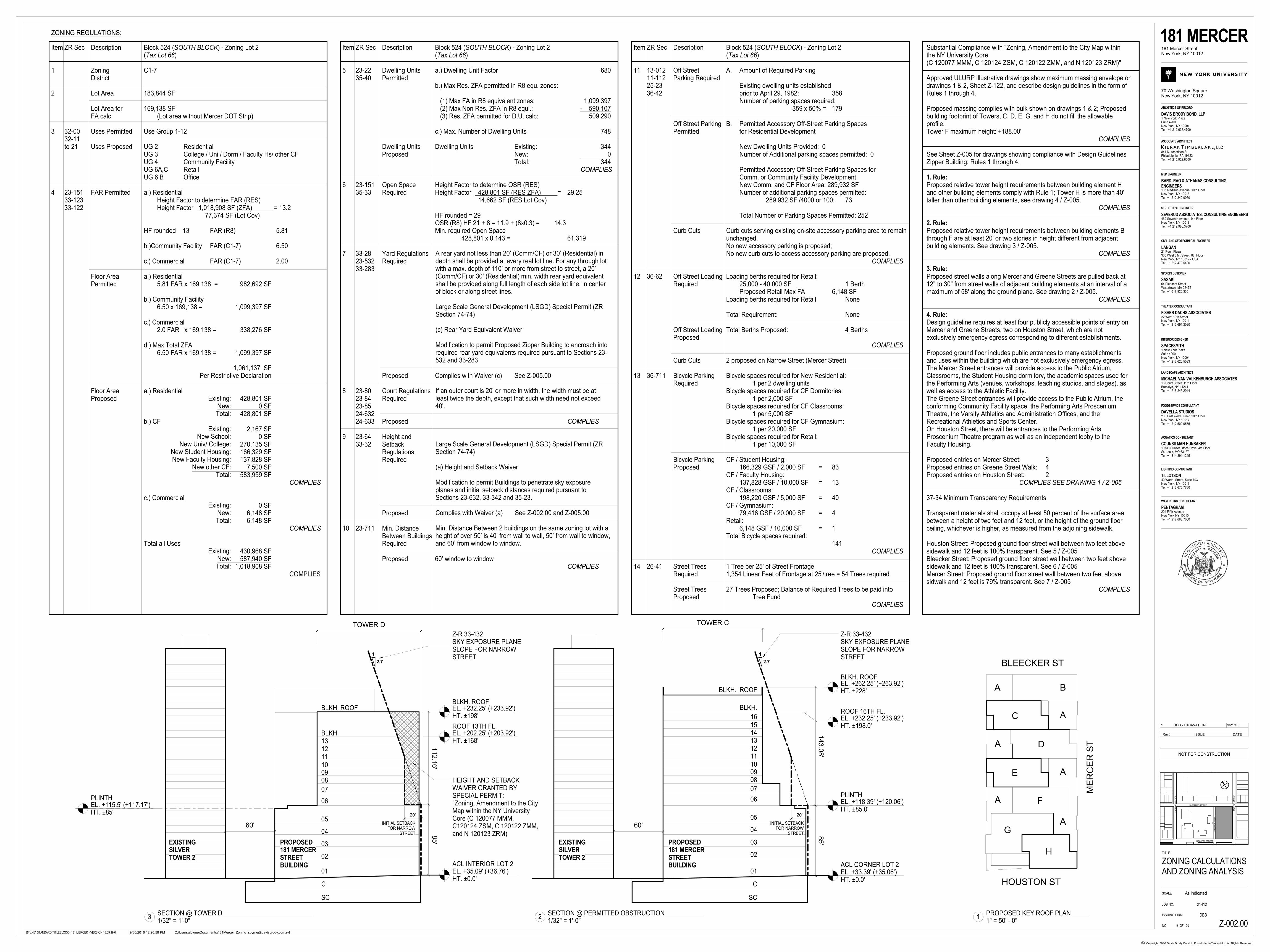
Substantial Compliance with "Zoning, Amendment to the City Map withinthe NY University Core(C 120077 MMM, C 120124 ZSM, C 120122 ZMM, and N 120123 ZRM)"
Approved ULURP illustrative drawings show maximum massing envelope ondrawings 1 & 2, Sheet Z-122, and describe design guidelines in the form ofRules 1 through 4.
Proposed massing complies with bulk shown on drawings 1 & 2; Proposedbuilding footprint of Towers, C, D, E, G, and H do not fill the allowableprofile.Tower F maximum height: +188.00'
COMPLIES
See Sheet Z-005 for drawings showing compliance with Design GuidelinesZipper Building: Rules 1 through 4.
1. Rule:Proposed relative tower height requirements between building element Hand other building elements comply with Rule 1; Tower H is more than 40'taller than other building elements, see drawing 4 / Z-005.
COMPLIES
2. Rule:Proposed relative tower height requirements between building elements Bthrough F are at least 20' or two stories in height different from adjacentbuilding elements. See drawing 3 / Z-005.
COMPLIES
3. Rule:Proposed street walls along Mercer and Greene Streets are pulled back at12" to 30" from street walls of adjacent building elements at an interval of amaximum of 58' along the ground plane. See drawing 2 / Z-005.
COMPLIES
4. Rule:Design guideline requires at least four publicly accessible points of entry onMercer and Greene Streets, two on Houston Street, which are notexclusively emergency egress corresponding to different establishments.
Proposed ground floor includes public entrances to many establichmentsand uses within the building which are not exclusively emergency egress.The Mercer Street entrances will provide access to the Public Atrium,Classrooms, the Student Housing dormitory, the academic spaces used forthe Performing Arts (venues, workshops, teaching studios, and stages), aswell as access to the Athletic Facility.The Greene Street entrances will provide access to the Public Atrium, theconforming Community Facility space, the Performing Arts ProsceniumTheatre, the Varsity Athletics and Administration Offices, and theRecreational Athletics and Sports Center.On Houston Street, there will be entrances to the Performing ArtsProscenium Theatre program as well as an independent lobby to theFaculty Housing.
Proposed entries on Mercer Street: 3Proposed entries on Greene Street Walk: 4Proposed entries on Houston Street: 2
COMPLIES SEE DRAWING 1 / Z-005
37-34 Minimum Transparency Requirements
Transparent materials shall occupy at least 50 percent of the surface areabetween a height of two feet and 12 feet, or the height of the ground floorceiling, whichever is higher, as measured from the adjoining sidewalk.
Houston Street: Proposed ground floor street wall between two feet abovesidewalk and 12 feet is 100% transparent. See 5 / Z-005Bleecker Street: Proposed ground floor street wall between two feet abovesidewalk and 12 feet is 100% transparent. See 6 / Z-005Mercer Street: Proposed ground floor street wall between two feet abovesidwalk and 12 feet is 79% transparent. See 7 / Z-005
COMPLIES
C
D
E
F
G
H
A
A
A
A
A
A
B
BLEECKER ST
HOUSTON ST
ME
RC
ER
ST
BLKH.
16
BLKH. ROOF
1514131211
100908
07
06
05
04
03
02
01
C
SC
85'
143. 0
8'
20'
INITIAL SETBACKFOR NARROW
STREET
ACL CORNER LOT 2
PLINTH
ROOF 16TH FL.
BLKH. ROOF
1
2.7
Z-R 33-432SKY EXPOSURE PLANESLOPE FOR NARROWSTREET
EXISTINGSILVERTOWER 2
PROPOSED181 MERCERSTREETBUILDING
EL. +262.25' (+263.92')HT. ±228'
EL. +232.25' (+233.92')HT. ±198.0'
EL. +118.39' (+120.06')HT. ±85.0'
EL. +33.39' (+35.06')HT. ±0.0'
TOWER C
60'
ZONING REGULATIONS:
Item ZR Sec Description Block 524 (SOUTH BLOCK) - Zoning Lot 2(Tax Lot 66)
1 Zoning C1-7District
2 Lot Area 183,844 SF
Lot Area for 169,138 SFFA calc (Lot area without Mercer DOT Strip)
3 32-00 Uses Permitted Use Group 1-1232-11to 21 Uses Proposed UG 2 Residential
UG 3 College / Uni / Dorm / Faculty Hs/ other CFUG 4 Community FacilityUG 6A,C RetailUG 6 B Office
4 23-151 FAR Permitted a.) Residential33-123 Height Factor to determine FAR (RES)33-122 Height Factor 1,018,908 SF (ZFA) = 13.2
77,374 SF (Lot Cov)
HF rounded 13 FAR (R8) 5.81
b.)Community Facility FAR (C1-7) 6.50
c.) Commercial FAR (C1-7) 2.00
Floor Area a.) ResidentialPermitted 5.81 FAR x 169,138 =
b.) Community Facility6.50 x 169,138 =
c.) Commercial2.0 FAR x 169,138 =
d.) Max Total ZFA6.50 FAR x 169,138 =
Floor Area a.) ResidentialProposed
b.) CF
COMPLIES
c.) Commercial
COMPLIES
Total all Uses
COMPLIES
982,692 SF
1,099,397 SF
338,276 SF
1,099,397 SF
1,061,137 SFPer Restrictive Declaration
428,801 SF0 SF
428,801 SF
2,167 SF0 SF
270,135 SF166,329 SF137,828 SF
7,500 SF583,959 SF
0 SF6,148 SF6,148 SF
430,968 SF587,940 SF
1,018,908 SF
Existing:New:Total:
Existing:New School:
New Univ/ College:New Student Housing:New Faculty Housing:
New other CF:Total:
Existing:New:Total:
Existing:New:Total:
Item ZR Sec Description Block 524 (SOUTH BLOCK) - Zoning Lot 2(Tax Lot 66)
11 13-012 Off Street A. Amount of Required Parking11-112 Parking Required25-23 Existing dwelling units established36-42 prior to April 29, 1982: 358
Number of parking spaces required:359 x 50% = 179
Off Street Parking B. Permitted Accessory Off-Street Parking SpacesPermitted for Residential Development
New Dwelling Units Provided: 0Number of Additional parking spaces permitted: 0
Permitted Accessory Off-Street Parking Spaces forComm. or Community Facility DevelopmentNew Comm. and CF Floor Area: 289,932 SFNumber of additional parking spaces permitted:
289,932 SF /4000 or 100: 73
Total Number of Parking Spaces Permitted: 252
Curb Cuts Curb cuts serving existing on-site accessory parking area to remainunchanged.No new accessory parking is proposed;No new curb cuts to access accessory parking are proposed.
COMPLIES
12 36-62 Off Street Loading Loading berths required for Retail:Required 25,000 - 40,000 SF 1 Berth
Proposed Retail Max FA 6,148 SFLoading berths required for Retail None
Total Requirement: None
Off Street Loading Total Berths Proposed: 4 BerthsProposed
COMPLIES
Curb Cuts 2 proposed on Narrow Street (Mercer Street)
13 36-711 Bicycle Parking Bicycle spaces required for New Residential:Required 1 per 2 dwelling units
Bicycle spaces required for CF Dormitories:1 per 2,000 SF
Bicycle spaces required for CF Classrooms:1 per 5,000 SF
Bicycle spaces required for CF Gymnasium:1 per 20,000 SF
Bicycle spaces required for Retail:1 per 10,000 SF
Bicycle Parking CF / Student Housing:Proposed 166,329 GSF / 2,000 SF = 83
CF / Faculty Housing:137,828 GSF / 10,000 SF = 13
CF / Classrooms:198,220 GSF / 5,000 SF = 40
CF / Gymnasium:79,416 GSF / 20,000 SF = 4
Retail:6,148 GSF / 10,000 SF = 1
Total Bicycle spaces required:141
COMPLIES
14 26-41 Street Trees 1 Tree per 25' of Street FrontageRequired 1,354 Linear Feet of Frontage at 25'/tree = 54 Trees required
Street Trees 27 Trees Proposed; Balance of Required Trees to be paid intoProposed Tree Fund
COMPLIES
Item ZR Sec Description Block 524 (SOUTH BLOCK) - Zoning Lot 2(Tax Lot 66)
5 23-22 Dwelling Units a.) Dwelling Unit Factor35-40 Permitted
b.) Max Res. ZFA permitted in R8 equ. zones:
(1) Max FA in R8 equivalent zones: (2) Max Non Res. ZFA in R8 equi.: (3) Res. ZFA permitted for D.U. calc:
c.) Max. Number of Dwelling Units
Dwelling Units Dwelling Units Existing:Proposed New:
Total:COMPLIES
6 23-151 Open Space Height Factor to determine OSR (RES)35-33 Required Height Factor 428,801 SF (RES ZFA) = 29.25
14,662 SF (RES Lot Cov)
HF rounded = 29OSR (R8) HF 21 + 8 = 11.9 + (8x0.3) = 14.3Min. required Open Space
428,801 x 0.143 = 61,319
7 33-28 Yard Regulations 23-532 Required33-283
Proposed Complies with Waiver (c) See Z-005.00
8 23-80 Court Regulations23-84 Required23-8524-63224-633 Proposed COMPLIES
9 23-64 Height and33-32 Setback
RegulationsRequired
Proposed
10 23-711 Min. DistanceBetween BuildingsRequired
Proposed 60’ window to windowCOMPLIES
A rear yard not less than 20’ (Comm/CF) or 30’ (Residential) indepth shall be provided at every real lot line. For any through lotwith a max. depth of 110’ or more from street to street, a 20’(Comm/CF) or 30’ (Residential) min. width rear yard equivalentshall be provided along full length of each side lot line, in centerof block or along street lines.
Large Scale General Development (LSGD) Special Permit (ZRSection 74-74)
(c) Rear Yard Equivalent Waiver
Modification to permit Proposed Zipper Building to encroach intorequired rear yard equivalents required pursuant to Sections 23-532 and 33-283
If an outer court is 20' or more in width, the width must be atleast twice the depth, except that such width need not exceed40'.
Large Scale General Development (LSGD) Special Permit (ZRSection 74-74)
(a) Height and Setback Waiver
Modification to permit Buildings to penetrate sky exposureplanes and initial setback distances required pursuant toSections 23-632, 33-342 and 35-23.
Complies with Waiver (a) See Z-002.00 and Z-005.00
Min. Distance Between 2 buildings on the same zoning lot with aheight of over 50’ is 40’ from wall to wall, 50’ from wall to window,and 60’ from window to window.
680
1,099,397- 590,107
509,290
748
3440
344
BLKH. ROOF
BLKH.131211
100908
07
06
05
04
03
02
01
C
SC
20'
INITIAL SETBACKFOR NARROW
STREET
ACL INTERIOR LOT 2
PLINTH
ROOF 13TH FL.
BLKH. ROOF
1
2.7
Z-R 33-432SKY EXPOSURE PLANESLOPE FOR NARROWSTREET
EXISTINGSILVERTOWER 2
PROPOSED181 MERCERSTREETBUILDING
EL. +232.25' (+233.92')HT. ±198'
EL. +202.25' (+203.92')HT. ±168'
EL. +115.5' (+117.17')HT. ±85'
EL. +35.09' (+36.76')HT. ±0.0'
85'
112.1
6'
HEIGHT AND SETBACKWAIVER GRANTED BYSPECIAL PERMIT:"Zoning, Amendment to the CityMap within the NY UniversityCore (C 120077 MMM,C120124 ZSM, C 120122 ZMM,and N 120123 ZRM)
TOWER D
60'
LA
GU
AR
DIA
PL
AC
E
BLEECKER STREET
HOUSTON STREET
ME
RC
ER
ST
RE
ET
GR
EE
NE
ST
RE
ET
SCALE
Copyright 2016 Davis Brody Bond LLP and KieranTimberlake, All Rights Reserved©
TITLE
OF
, LLC841 N. American St.Philadelphia, PA 19123Tel: +1.215.922.6600
ASSOCIATE ARCHITECT
ARCHITECT OF RECORD
MEP ENGINEER
STRUCTURAL ENGINEER
CIVIL AND GEOTECHNICAL ENGINEER
SPORTS DESIGNER
DAVIS BRODY BOND, LLP
BARD, RAO & ATHANAS CONSULTINGENGINEERS
SEVERUD ASSOCIATES, CONSULTING ENGINEERS
LANGAN
SASAKI
1 New York PlazaSuite 4200New York, NY 10004Tel: +1.212.633.4700
105 Madison Avenue, 10th FloorNew York, NY 10016Tel: +1.212.840.0060
469 Seventh Avenue, 9th FloorNew York, NY 10018Tel: +1.212.986.3700
21 Penn Plaza360 West 31st Street, 8th FloorNew York, NY 10017 - USATel: +1.212.479.5400
64 Pleasant StreetWatertown, MA 02472Tel: +1.617.926.330
THEATER CONSULTANT
FISHER DACHS ASSOCIATES22 West 19th StreetNew York, NY 10011Tel: +1.212.691.3020
INTERIOR DESIGNER
SPACESMITH1 New York PlazaSuite 4200New York, NY 10004Tel: +1.212.620.5583
181 MERCER181 Mercer StreetNew York, NY 10012
70 Washington SquareNew York, NY 10012
JOB NO.
ISSUING FIRM
NO.
21412
DBB
36" x 48" STANDARD TITLEBLOCK - 181 MERCER - VERSION 16.09.19.0
LANDSCAPE ARCHITECT
MICHAEL VAN VALKENBURGH ASSOCIATES16 Court Street, 11th FloorBrooklyn, NY 11241Tel: +1.718.243.2044
FOODSERVICE CONSULTANT
DAVELLA STUDIOS205 East 42nd Street, 20th FloorNew York, NY 10017Tel: +1.212.500.0565
AQUATICS CONSULTANT
COUNSILMAN-HUNSAKER10733 Sunset Office Drive, 4th FloorSt. Louis, MO 63127Tel: +1.314.894.1245
LIGHTING CONSULTANT
TILLOTSON40 Worth Street, Suite 703New York, NY 10013Tel: +1.212.675.7760
WAYFINDING CONSULTANT
PENTAGRAM204 Fifth AvenueNew York NY 10010Tel: +1.212.683.7000
As indicated
C:\Users\sbyrne\Documents\[email protected]/30/2016 12:20:59 PM
Z-002.00
ZONING CALCULATIONSAND ZONING ANALYSIS
365
NOT FOR CONSTRUCTION
SECTION @ PERMITTED OBSTRUCTION1/32" = 1'-0"
2SECTION @ TOWER D1/32" = 1'-0"
3PROPOSED KEY ROOF PLAN1" = 50' - 0"
1
Rev# ISSUE DATE
1 DOB - EXCAVATION 9/21/16
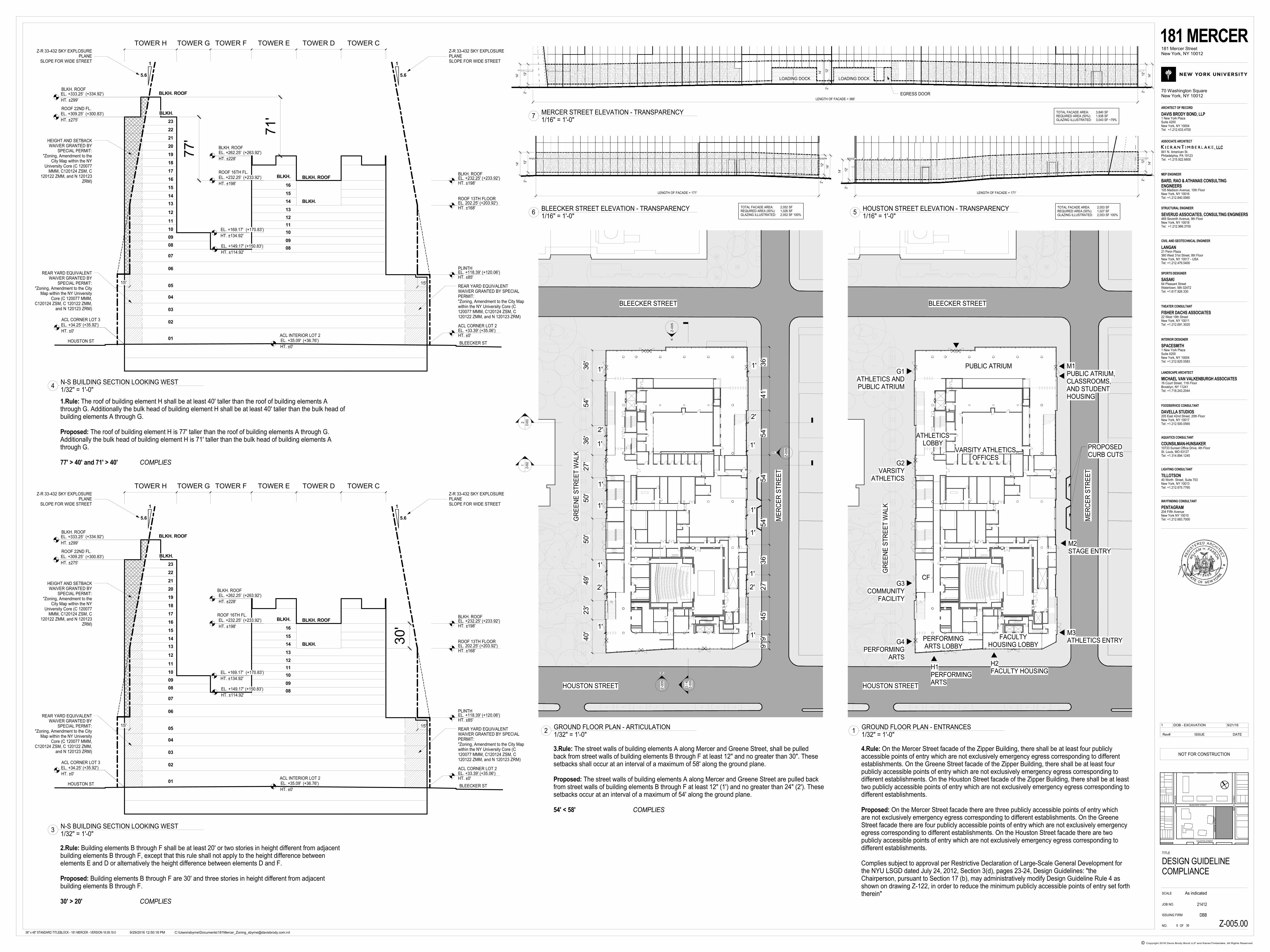
EL. +34.25'
EL. +232.25'
HT. ±198'
EL. +149.17'
HT. ±114.92'
EL. +169.17'
HT. ±134.92'
15'
ACL CORNER LOT 2
15'
HOUSTON ST
HT. ±0'
BLEECKER ST
16
15
14
13
12
11
10
09
08
07
06
05
04
03
02
01
17
18
19
20
21
22
BLKH.
16
15
14
13
12
11
10
09
08
BLKH.
BLKH. ROOF
ROOF 16TH FL.
ACL CORNER LOT 3
EL. +35.09'
HT. ±0'
ACL INTERIOR LOT 2
HT. ±228'
EL. +262.25'
EL. +33.39' (+35.06')HT. ±0'
77'
(+263.92')
(+233.92')
(+170.83')
(+150.83')
(+35.92')
(+36.76')
1
5.6
1
5.6
Z-R 33-432 SKY EXPLOSUREPLANESLOPE FOR WIDE STREET
Z-R 33-432 SKY EXPLOSUREPLANE
SLOPE FOR WIDE STREET
TOWER CTOWER DTOWER ETOWER FTOWER GTOWER H
BLKH. ROOF
23
REAR YARD EQUIVALENTWAIVER GRANTED BY
SPECIAL PERMIT:"Zoning, Amendment to the City
Map within the NY UniversityCore (C 120077 MMM,
C120124 ZSM, C 120122 ZMM,and N 120123 ZRM)
ROOF 22ND FL.
BLKH. ROOF(+334.92')
(+300.83')
EL. +333.25'
HT. ±299'
HEIGHT AND SETBACKWAIVER GRANTED BY
SPECIAL PERMIT:"Zoning, Amendment to the
City Map within the NYUniversity Core (C 120077
MMM, C120124 ZSM, C120122 ZMM, and N 120123
ZRM)
EL. +309.25'
HT. ±275'
BLKH. ROOFEL. +232.25' (+233.92')HT. ±198'
EL. 202.25' (+203.92')HT. ±168'
ROOF 13TH FLOORBLKH.
BLKH. ROOF
71'
REAR YARD EQUIVALENTWAIVER GRANTED BY SPECIALPERMIT:"Zoning, Amendment to the City Mapwithin the NY University Core (C120077 MMM, C120124 ZSM, C120122 ZMM, and N 120123 ZRM)
PLINTHEL. +118.39' (+120.06')HT. ±85'
ME
RC
ER
ST
RE
ET
GR
EE
NE
ST
RE
ET
WA
LK
BLEECKER STREET
HOUSTON STREET
M1PUBLIC ATRIUM,CLASSROOMS,AND STUDENTHOUSING
M2STAGE ENTRY
M3ATHLETICS ENTRY
PUBLIC ATRIUM
ATHLETICSLOBBY
VARSITY ATHLETICSOFFICES
CF
PERFORMINGARTS LOBBY
FACULTYHOUSING LOBBY
G1ATHLETICS ANDPUBLIC ATRIUM
G2VARSITY
ATHLETICS
G3COMMUNITY
FACILITY
G4PERFORMING
ARTS
H1PERFORMINGARTS
H2FACULTY HOUSING
PROPOSEDCURB CUTSZ
-005
Z-0
05
Z-0
05
2
Z-0
02
ME
RC
ER
ST
RE
ET
GR
EE
NE
ST
RE
ET
WA
LK
1'
9'9'
45'
27'
36'
54'
54'
54'
41'
36'
1'
2'
1'
1'
1'
1'
2'
40'
23'
49'
50'
50'
27'
36'
54'
36'
1'
2'
1'
1'
1'
1'
2'
1'
BLEECKER STREET
HOUSTON STREET 3
Z-0
05
1
Z-0
02
6
7
5
3 /
4Z
-00
5
EL. +232.25'
15'
1
5.6
1
5.6
Z-R 33-432 SKY EXPLOSUREPLANESLOPE FOR WIDE STREET
15'
HOUSTON ST BLEECKER ST
Z-R 33-432 SKY EXPLOSUREPLANE
SLOPE FOR WIDE STREET
16
BLKH.
15
14
13
12
11
10
09
08
07
06
05
04
03
02
01
17
18
19
20
21
22
23
16
15
14
13
12
11
10
09
08
BLKH.
BLKH. ROOF
ROOF 16TH FL.
EL. +35.09'
HT. ±0'
ACL INTERIOR LOT 2
EL. +262.25'
PLINTH
BLKH. ROOF
TOWER CTOWER DTOWER ETOWER FTOWER GTOWER H
EL. +34.25'
HT. ±0'
ROOF 22ND FL.
BLKH. ROOF
ACL CORNER LOT 3
EL. +232.25' (+233.92')HT. ±198'
EL. 202.25' (+203.92')HT. ±168'
EL. +118.39' (+120.06')HT. ±85'
(+263.92')
(+233.92')
(+334.92')
(+300.83')
(+35.92')
(+36.76')
30'
ROOF 13TH FLOORBLKH.
BLKH. ROOF
BLKH. ROOF
EL. +309.25'
HT. ±275'
EL. +333.25'
HT. ±299'
ACL CORNER LOT 2EL. +33.39' (+35.06')HT. ±0'
REAR YARD EQUIVALENTWAIVER GRANTED BY
SPECIAL PERMIT:"Zoning, Amendment to the City
Map within the NY UniversityCore (C 120077 MMM,
C120124 ZSM, C 120122 ZMM,and N 120123 ZRM)
HEIGHT AND SETBACKWAIVER GRANTED BY
SPECIAL PERMIT:"Zoning, Amendment to the
City Map within the NYUniversity Core (C 120077
MMM, C120124 ZSM, C120122 ZMM, and N 120123
ZRM)
REAR YARD EQUIVALENTWAIVER GRANTED BY SPECIALPERMIT:"Zoning, Amendment to the City Mapwithin the NY University Core (C120077 MMM, C120124 ZSM, C120122 ZMM, and N 120123 ZRM)
HT. ±198'
HT. ±228'
EL. +149.17'
HT. ±114.92'
EL. +169.17'
HT. ±134.92'
(+170.83')
(+150.83')
LOADING DOCK LOADING DOCK
TOTAL FACADE AREA: 3,840 SFREQUIRED AREA (50%): 1,938 SFGLAZING ILLUSTRATED: 3,043 SF ~79%
12
'2
'
14
'
12
'2
'
14
'
12
'2
'
14
'
LENGTH OF FACADE = 366'
EGRESS DOOR
TOTAL FACADE AREA: 2,052 SFREQUIRED AREA (50%): 1,026 SFGLAZING ILLUSTRATED: 2,052 SF 100%
LENGTH OF FACADE = 171'
12
'2
'
14
'
12
'2
'
14
'
TOTAL FACADE AREA: 2,053 SFREQUIRED AREA (50%): 1,027 SFGLAZING ILLUSTRATED: 2,053 SF 100%
LENGTH OF FACADE = 171'
12
'2
'
14
'
12
'2
'
14
'
LA
GU
AR
DIA
PL
AC
E
BLEECKER STREET
HOUSTON STREET
ME
RC
ER
ST
RE
ET
GR
EE
NE
ST
RE
ET
SCALE
Copyright 2016 Davis Brody Bond LLP and KieranTimberlake, All Rights Reserved©
TITLE
OF
, LLC841 N. American St.Philadelphia, PA 19123Tel: +1.215.922.6600
ASSOCIATE ARCHITECT
ARCHITECT OF RECORD
MEP ENGINEER
STRUCTURAL ENGINEER
CIVIL AND GEOTECHNICAL ENGINEER
SPORTS DESIGNER
DAVIS BRODY BOND, LLP
BARD, RAO & ATHANAS CONSULTINGENGINEERS
SEVERUD ASSOCIATES, CONSULTING ENGINEERS
LANGAN
SASAKI
1 New York PlazaSuite 4200New York, NY 10004Tel: +1.212.633.4700
105 Madison Avenue, 10th FloorNew York, NY 10016Tel: +1.212.840.0060
469 Seventh Avenue, 9th FloorNew York, NY 10018Tel: +1.212.986.3700
21 Penn Plaza360 West 31st Street, 8th FloorNew York, NY 10017 - USATel: +1.212.479.5400
64 Pleasant StreetWatertown, MA 02472Tel: +1.617.926.330
THEATER CONSULTANT
FISHER DACHS ASSOCIATES22 West 19th StreetNew York, NY 10011Tel: +1.212.691.3020
INTERIOR DESIGNER
SPACESMITH1 New York PlazaSuite 4200New York, NY 10004Tel: +1.212.620.5583
181 MERCER181 Mercer StreetNew York, NY 10012
70 Washington SquareNew York, NY 10012
JOB NO.
ISSUING FIRM
NO.
21412
DBB
36" x 48" STANDARD TITLEBLOCK - 181 MERCER - VERSION 16.09.19.0
LANDSCAPE ARCHITECT
MICHAEL VAN VALKENBURGH ASSOCIATES16 Court Street, 11th FloorBrooklyn, NY 11241Tel: +1.718.243.2044
FOODSERVICE CONSULTANT
DAVELLA STUDIOS205 East 42nd Street, 20th FloorNew York, NY 10017Tel: +1.212.500.0565
AQUATICS CONSULTANT
COUNSILMAN-HUNSAKER10733 Sunset Office Drive, 4th FloorSt. Louis, MO 63127Tel: +1.314.894.1245
LIGHTING CONSULTANT
TILLOTSON40 Worth Street, Suite 703New York, NY 10013Tel: +1.212.675.7760
WAYFINDING CONSULTANT
PENTAGRAM204 Fifth AvenueNew York NY 10010Tel: +1.212.683.7000
As indicated
C:\Users\sbyrne\Documents\[email protected]/29/2016 12:50:18 PM
Z-005.00
DESIGN GUIDELINECOMPLIANCE
368
NOT FOR CONSTRUCTION
GROUND FLOOR PLAN - ARTICULATION1/32" = 1'-0"
2GROUND FLOOR PLAN - ENTRANCES1/32" = 1'-0"
1
N-S BUILDING SECTION LOOKING WEST1/32" = 1'-0"
3
N-S BUILDING SECTION LOOKING WEST1/32" = 1'-0"
4
1.Rule: The roof of building element H shall be at least 40' taller than the roof of building elements Athrough G. Additionally the bulk head of building element H shall be at least 40' taller than the bulk head ofbuilding elements A through G.
Proposed: The roof of building element H is 77' taller than the roof of building elements A through G.Additionally the bulk head of building element H is 71' taller than the bulk head of building elements Athrough G.
77' > 40' and 71' > 40' COMPLIES
2.Rule: Building elements B through F shall be at least 20' or two stories in height different from adjacentbuilding elements B through F, except that this rule shall not apply to the height difference betweenelements E and D or alternatively the height difference between elements D and F.
Proposed: Building elements B through F are 30' and three stories in height different from adjacentbuilding elements B through F.
30' > 20' COMPLIES
3.Rule: The street walls of building elements A along Mercer and Greene Street, shall be pulledback from street walls of building elements B through F at least 12" and no greater than 30". Thesesetbacks shall occur at an interval of a maximum of 58' along the ground plane.
Proposed: The street walls of building elements A along Mercer and Greene Street are pulled backfrom street walls of building elements B through F at least 12" (1') and no greater than 24" (2'). Thesesetbacks occur at an interval of a maximum of 54' along the ground plane.
54' < 58' COMPLIES
4.Rule: On the Mercer Street facade of the Zipper Building, there shall be at least four publiclyaccessible points of entry which are not exclusively emergency egress corresponding to differentestablishments. On the Greene Street facade of the Zipper Building, there shall be at least fourpublicly accessible points of entry which are not exclusively emergency egress corresponding todifferent establishments. On the Houston Street facade of the Zipper Building, there shall be at leasttwo publicly accessible points of entry which are not exclusively emergency egress corresponding todifferent establishments.
Proposed: On the Mercer Street facade there are three publicly accessible points of entry whichare not exclusively emergency egress corresponding to different establishments. On the GreeneStreet facade there are four publicly accessible points of entry which are not exclusively emergencyegress corresponding to different establishments. On the Houston Street facade there are twopublicly accessible points of entry which are not exclusively emergency egress corresponding todifferent establishments.
Complies subject to approval per Restrictive Declaration of Large-Scale General Development forthe NYU LSGD dated July 24, 2012, Section 3(d), pages 23-24, Design Guidelines: "theChairperson, pursuant to Section 17 (b), may administratively modify Design Guideline Rule 4 asshown on drawing Z-122, in order to reduce the minimum publicly accessible points of entry set forththerein"
HOUSTON STREET ELEVATION - TRANSPARENCY1/16" = 1'-0"
5BLEECKER STREET ELEVATION - TRANSPARENCY1/16" = 1'-0"
6
MERCER STREET ELEVATION - TRANSPARENCY1/16" = 1'-0"
7
Rev# ISSUE DATE
1 DOB - EXCAVATION 9/21/16
APPENDIX 2
Remedial Investigation Report
APPENDIX 3
Citizen Participation Plan
1
APPENDIX 3
CITIZEN PARTICIPATION PLAN
The NYC Office of Environmental Remediation and New York University (NYU) have
established this Citizen Participation Plan because the opportunity for citizen participation is an
important component of the NYC Voluntary Cleanup Program. This Citizen Participation Plan
describes how information about the project will be disseminated to the Community during the
remedial process. As part of its obligations under the NYC VCP, NYU will maintain a
repository for project documents and provide public notice at specified times throughout the
remedial program. This Plan also takes into account potential environmental justice concerns in
the community that surrounds the project Site. Under this Citizen Participation Plan, project
documents and work plans are made available to the public in a timely manner. Public comment
on work plans is strongly encouraged during public comment periods. Work plans are not
approved by the NYC Office of Environmental Remediation (OER) until public comment
periods have expired and all comments are formally reviewed. An explanation of cleanup plans
in the form of a public meeting or informational session is available upon request to OER’s
project manager assigned to this Site, Horace Zhang, who can be contacted about these issues or
any others questions, comments or concerns that arise during the remedial process at (212) 788-
8484.
Project Contact List: OER has established a Site Contact List for this project to provide
public notices in the form of fact sheets to interested members of the Community.
Communications will include updates on important information relating to the progress of the
cleanup program at the Site as well as to request public comments on the cleanup plan. The
Project Contact List includes owners and occupants of adjacent buildings and homes, principal
administrators of nearby schools, hospitals and day care centers, the public water supplier that
serves the area, established document repositories, the representative Community Board, City
Council members, other elected representatives and any local Brownfield Opportunity Area
2
(BOA) grantee organizations. Any member of the public or organization will be added to the
Site Contact List on request. A copy of the Site Contact List is maintained by OER’s project
manager. If you would like to be added to the Project Contact List, contact NYC OER at (212)
788-8841 or by email at [email protected].
Repositories: A document repository is maintained online. Internet access to view OER’s
document repositories is available at public libraries. This document repository is intended to
house, for community review, all principal documents generated during the cleanup program
including Remedial Investigation plans and reports, Remedial Action work plans and reports,
and all public notices and fact sheets produced during the lifetime of the remedial project. The
library nearest the Site is:
Mulberry Street Library
10 Jersey Street
New York, New York 10012
(212) 966-3424
M-Th: 10AM-7PM; F-S: 10AM-5PM; closed Sundays
Digital Documentation: NYC OER requires the use of digital documents in our repository
as a means of minimizing paper use while also increasing convenience in access and ease of use.
Issues of Public Concern: There are no environmental justice or other specific issues of
public concern related to the RAWP.
Public Notice and Public Comment: Public notice to all members of the Project Contact
List is required at three major steps during the performance of the cleanup program (listed
below) and at other points that may be required by OER. Notices will include Fact Sheets with
descriptive project summaries, updates on recent and upcoming project activities, repository
information, and important phone and email contact information. All notices will be reviewed
and approved by OER prior to distribution and mailed by the Enrollee. Public comment is
solicited in public notices for all work plans developed under the NYC Voluntary Cleanup
3
Program. Final review of all work plans by OER will consider all public comments. Approval
will not be granted until the public comment period has been completed.
Citizen Participation Milestones: Public notice and public comment activities occur at
several steps during a typical NYC VCP project. These steps include:
• Public Notice of the availability of the Remedial Investigation Report and Remedial
Action Work Plan and a 30-day public comment period on the Remedial Action
Work Plan: Public notice in the form of a Fact Sheet is sent to all parties listed on the
Site Contact List announcing the availability of the Remedial Investigation Report and
Remedial Action Work Plan and the initiation of a 30-day public comment period on the
Remedial Action Work Plan. The Fact Sheet summarizes the findings of the RIR and
provides details of the RAWP. The public comment period will be extended an
additional 15 days upon public request. A public meeting or informational session will
be conducted by OER upon request.
• Public Notice announcing the approval of the RAWP and the start of remediation:
Public notice in the form of a Fact Sheet is sent to all parties listed on the Site Contact
List announcing the approval of the RAWP and the start of remediation.
• Public Notice announcing the completion of remediation, designation of
Institutional and Engineering Controls and issuance of the Notice of Completion:
Public notice in the form of a Fact Sheet is sent to all parties listed on the Site Contact
List announcing the completion of remediation, providing a list of all Institutional and
Engineering Controls implemented for to the Site and announcing the issuance of the
Notice of Completion.
APPENDIX 4
Sustainability Statement
1
APPENDIX 4
SUSTAINABILITY STATEMENT
This Sustainability Statement documents sustainable activities and green remediation efforts
planned under this remedial action.
Reuse of Clean, Recyclable Materials and Reduced Consumption of Non-
Renewable Resources:
Reuse of clean, locally-derived recyclable materials reduces consumption of non-renewable
virgin resources and can provide energy savings and greenhouse gas reduction.
An estimate of the quantity (in tons) of clean, non-virgin materials (reported by type of material)
reused under this plan will be quantified and reported in the RAR.
Reduced Energy Consumption and Promotion of Greater Energy Efficiency:
Reduced energy consumption lowers greenhouse gas emissions, improves local air quality,
lessens in-city power generation requirements, can lower traffic congestion, and provides
substantial cost savings.
Best efforts will be made to quantify energy efficiencies achieved during the remediation and
will be reported in the RAR. Where energy savings cannot be easily quantified, a gross indicator
of the amount of energy saved or the means by which energy savings was achieved will be
reported.
Conversion to Clean Fuels:
Use of clean fuel improves NYC’s air quality by reducing harmful emissions.
An estimate of the volume of clean fuels used during remedial activities will be quantified and
reported in the RAR.
2
Recontamination Control:
Recontamination after cleanup and redevelopment is completed undermines the value of work
performed, may result in a property that is less protective of public health or the environment,
and may necessitate additional cleanup work later or impede future redevelopment.
Recontamination can arise from future releases that occur within the property or by influx of
contamination from off-Site.
An estimate of the area of the Site that utilizes recontamination controls under this plan will be
reported in the RAR in square feet.
Stormwater Retention:
Stormwater retention improves water quality by lowering the rate of combined stormwater and
sewer discharges to NYC’s sewage treatment plants during periods of precipitation, and reduces
the volume of untreated influent to local surface waters.
An estimate of the enhanced stormwater retention capability of the redevelopment project will be
included in the RAR.
Linkage with Green Building: Green buildings provide a multitude of benefits to the city
across a broad range of areas, such as reduction of energy consumption, conservation of
resources, and reduction in toxic materials use.
The number of Green Buildings that are associated with this brownfield redevelopment property
will be reported in the RAR. The total square footage of green building space created as a
function of this brownfield redevelopment will be quantified for residential, commercial and
industrial/manufacturing uses.
Paperless Voluntary Cleanup Program: New York University (NYU) is participating
in OER’s Paperless Voluntary Cleanup Program. Under this program, submission of electronic
documents will replace submission of hard copies for the review of project documents,
communications and milestone reports.
3
Low-Energy Project Management Program: NYU is participating in OER’s low-
energy project management program. Under this program, whenever possible, meetings are held
using remote communication technologies, such as videoconferencing and teleconferencing to
reduce energy consumption and traffic congestion associated with personal transportation.
Trees and Plantings: Trees and other plantings provide habitat and add to NYC’s
environmental quality in a wide variety of ways. Native plant species and native habitat provide
optimal support to local fauna, promote local biodiversity, and require less maintenance.
An estimate of the land area that will be vegetated, including the number of trees planted or
preserved, will be reported in square feet in the RAR.
APPENDIX 5
Soil/Materials Management Plan
1
APPENDIX 5
SOIL/MATERIALS MANAGEMENT PLAN
1.1 Soil Screening Methods
Visual, olfactory and PID soil screening and assessment will be performed under the supervision
of a Qualified Environmental Professional and will be reported in the final remedial report. Soil
screening will be performed during invasive work performed during the remedy and
development phases prior to issuance of final signoff by OER.
1.2 Stockpile Methods
Excavated soil from suspected areas of contamination (e.g., hot spots, USTs, drains, etc.) will be
stockpiled separately and will be segregated from clean soil and construction materials.
Stockpiles will be used only when necessary and will be removed as soon as practicable. While
stockpiles are in place, they will be inspected daily, and before and after every storm event.
Results of inspections will be recorded in a logbook and maintained at the Site and available for
inspection by OER. Excavated soils will be stockpiled on, at minimum, double layers of 8-mil
minimum sheeting, will be kept covered at all times with appropriately anchored plastic tarps,
and will be routinely inspected. Broken or ripped tarps will be promptly replaced.
All stockpile activities will be compliant with applicable laws and regulations. Soil stockpile
areas will be appropriately graded to control run-off in accordance with applicable laws and
regulations. Stockpiles of excavated soils and other materials shall be located at least 50 feet
from the property boundaries, where possible. Hay bales or equivalent will surround soil
stockpiles except for areas where access by equipment is required. Silt fencing and hay bales will
be used as needed near catch basins, surface waters and other discharge points.
1.3 Characterization of Excavated Materials
Soil/fill or other excavated media that is transported off-Site for disposal will be sampled in a
manner required by the receiving facility, and in compliance with applicable laws and
regulations. Soils proposed for reuse on-Site will be managed as defined in this plan.
2
1.4 Materials Excavation, Load-Out, and Departure
The PE/QEP overseeing the remedial action will:
• oversee remedial work and the excavation and load-out of excavated material;
• ensure that there is a party responsible for the safe execution of invasive and other work
performed under this work plan;
• ensure that Site development activities and development-related grading cuts will not
interfere with, or otherwise impair or compromise the remedial activities proposed in this
RAWP;
• ensure that the presence of utilities and easements on the Site has been investigated and
that any identified risks from work proposed under this plan are properly addressed by
appropriate parties;
• ensure that all loaded outbound trucks are inspected and cleaned if necessary before
leaving the Site;
• ensure that all egress points for truck and equipment transport from the Site will be kept
clean of Site-derived materials during Site remediation.
Locations where vehicles exit the Site shall be inspected daily for evidence of soil tracking off
premises. Cleaning of the adjacent streets will be performed as needed to maintain a clean
condition with respect to Site-derived materials.
Open and uncontrolled mechanical processing of historical fill and contaminated soil on-Site will
not be performed without prior OER approval.
1.5 Off-Site Materials Transport
Loaded vehicles leaving the Site will comply with all applicable materials transportation
requirements (including appropriate covering, manifests, and placards) in accordance with
applicable laws and regulations, including use of licensed haulers in accordance with 6 NYCRR
Part 364. If loads contain wet material capable of causing leakage from trucks, truck liners will
be used. Queuing of trucks will be performed on-Site, when possible in order to minimize off
Site disturbance. Off-Site queuing will be minimized.
3
Outbound truck transport routes are described in the remedial report. This routing takes into
account the following factors: (a) limiting transport through residential areas and past sensitive
sites; (b) use of mapped truck routes; (c) minimizing off-Site queuing of trucks entering the
facility; (d) limiting total distance to major highways; (e) promoting safety in access to
highways; and (f) overall safety in transport. To the extent possible, all trucks loaded with Site
materials will travel from the Site using these truck routes. Trucks will not stop or idle in the
neighborhood after leaving the project Site.
1.6 Materials Disposal Off-Site
The following documentation will be established and reported by the PE/QEP for each disposal
destination used in this project to document that the disposal of regulated material exported from
the Site conforms with applicable laws and regulations: (1) a letter from the PE/QEP or Enrollee
to each disposal facility describing the material to be disposed and requesting written acceptance
of the material. This letter will state that material to be disposed is regulated material generated
at an environmental remediation Site in New York City under a governmental remediation
program. The letter will provide the project identity and the name and phone number of the
PE/QEP or Enrollee. The letter will include as an attachment a summary of all chemical data for
the material being transported; and (2) a letter from each disposal facility stating it is in receipt of
the correspondence (1, above) and is approved to accept the material. These documents will be
included in the final remedial report.
The Remedial Action Report will include an itemized account of the destination of all material
removed from the Site during this remedial action. Documentation associated with disposal of
all material will include records and approvals for receipt of the material. This information will
be presented in the final remedial report.
All impacted soil/fill or other waste excavated and removed from the Site will be managed as
regulated material and will be disposed in accordance with applicable laws and regulations.
Historic fill and contaminated soils taken off-Site will be handled as solid waste and will not be
disposed at a Part 360-16 Registration Facility (also known as a Soil Recycling Facility).
Waste characterization will be performed for off-Site disposal in a manner required by the
receiving facility and in conformance with its applicable permits. Waste characterization
sampling and analytical methods, sampling frequency, analytical results and QA/QC will be
4
reported in the final remedial report. A manifest system for off-Site transportation of exported
materials will be employed. Manifest information will be reported in the final remedial report.
Hazardous wastes derived from on-Site will be stored, transported, and disposed of in
compliance with applicable laws and regulations.
If disposal of soil/fill from this Site is proposed for unregulated disposal (i.e., clean soil removed
for development purposes), including transport to a Part 360-16 Registration Facility, a formal
request will be made for approval by OER with an associated plan compliant with 6NYCRR Part
360-16. This request and plan will include the location, volume and a description of the material
to be recycled, including verification that the material is not impacted by site uses and that the
material complies with receipt requirements for recycling under 6NYCRR Part 360. This
material will be appropriately handled on-Site to prevent mixing with impacted material.
1.7 Materials Reuse On-Site
Soil and fill that is derived from the property that meets the Soil Cleanup Objectives (SCOs)
established in this plan may be reused on-Site. The SCOs for on-Site reuse are listed in Section
4.2 of this cleanup plan. ‘Reuse on-Site’ means material that is excavated during the remedy or
development, does not leave the property, and is relocated within the same property and on land
with comparable levels of contaminants in soil/fill material, compliant with applicable laws and
regulations, and addressed pursuant to the NYC VCP agreement subject to Engineering and
Institutional Controls. The PE/QEP will ensure that reused materials are segregated from other
materials to be exported from the Site and that procedures defined for material reuse in this
remedial plan are followed. The expected location for placement of reused material is shown in
Section 4.2.
Organic matter (wood, roots, stumps, etc.) or other waste derived from clearing and grubbing of
the Site will not be buried on-Site. Soil or fill excavated from the site for grading or other
purposes will not be reused within a cover soil layer or within landscaping berms.
1.8 Demarcation
After completion of hotspot removal and any other invasive remedial activities, and prior to
backfilling, the top of the residual soil/fill will be defined by one of three methods: (1) placement
of a demarcation layer. The demarcation layer will consist of geosynthetic fencing or equivalent
5
material to be placed on the surface of residual soil/fill to provide an observable reference layer.
A description or map of the approximate depth of the demarcation layer will be provided in the
SMP; or (2) a land survey of the top elevation of residual soil/fill before the placement of cover
soils, pavement and associated sub-soils, or other materials or structures or, (3) all materials
beneath the approved cover will be considered impacted and subject to site management after the
remedy is complete. Demarcation may be established by one or any combination of these three
methods. As appropriate, a map showing the method of demarcation for the Site and all
associated documentation will be presented in the RAR.
This demarcation will constitute the top of the site management horizon. Materials within this
horizon require adherence to special conditions during future invasive activities as defined in the
Site Management Plan.
1.9 Import of Backfill Soil From Off-Site Sources
This Section presents the requirements for imported fill materials to be used below the cover
layer and within the clean soil cover layer. All imported soils will meet OER-approved backfill
and cover soil quality objectives for this Site. Imported soils will not exceed groundwater
protection standards established in Part 375. Imported soils for Track 1 remedial action projects
will not exceed Track 1 SCO’s.
A process will be established to evaluate sources of backfill and cover soil to be imported to the
Site, and will include an examination of source location, current and historical use(s), and any
applicable documentation. Material from industrial sites, spill sites, environmental remediation
sites or other potentially contaminated sites will not be imported to the Site.
The following potential sources may be used pending attainment of backfill and cover soil
quality objectives:
• Clean soil from construction projects at non-industrial sites in compliance with applicable
laws and regulations;
• Clean soil from roadway or other transportation-related projects in compliance with
applicable laws and regulations;
• Clean recycled concrete aggregate (RCA) from facilities permitted or registered by the
regulations of NYS DEC.
6
All materials received for import to the Site will be approved by a PE/QEP and will be in
compliance with provisions in this remedial plan. The final remedial report will report the
source of the fill, evidence that an inspection was performed on the source, chemical sampling
results, frequency of testing, and a Site map indicating the locations where backfill or soil cover
was placed.
All material will be subject to source screening and chemical testing. Inspection of imported fill
material will include visual, olfactory and PID screening for evidence of contamination.
Materials imported to the Site will be subject to inspection, as follows:
• Trucks with imported fill material will be in compliance with applicable laws and
regulations and will enter the Site at designated locations;
• The PE/QEP is responsible to ensure that every truck load of imported material is
inspected for evidence of contamination; and
• Fill material will be free of solid waste including pavement materials, debris, stumps,
roots, and other organic matter, as well as ashes, oil, perishables or foreign matter.
Composite samples of imported material will be taken at a minimum frequency of one sample
for every 500 cubic yards of material. Once it is determined that the fill material meets imported
backfill or cover soil chemical requirements and is non-hazardous, and lacks petroleum
contamination, the material will be loaded onto trucks for delivery to the Site.
Recycled concrete aggregate (RCA) will be imported from facilities permitted or registered by
NYSDEC. Facilities will be identified in the final remedial report. A PE/QEP is responsible to
ensure that the facility is compliant with 6NYCRR Part 360 registration and permitting
requirements for the period of acquisition of RCA. RCA imported from compliant facilities will
not require additional testing, unless required by NYSDEC under its terms for operation of the
facility. RCA imported to the Site must be derived from recognizable and uncontaminated
concrete. RCA material is not acceptable for, and will not be used as cover material.
1.10 Fluids Management
All liquids to be removed from the Site, including dewatering fluids, will be handled, transported
and disposed in accordance with applicable laws and regulations. Liquids discharged into the
New York City sewer system will receive prior approval by New York City Department of
Environmental Protection (NYC DEP). The NYC DEP regulates discharges to the New York
7
City sewers under Title 15, Rules of the City of New York Chapter 19. Discharge to the New
York City sewer system will require an authorization and sampling data demonstrating that the
groundwater meets the City’s discharge criteria. The dewatering fluid will be pretreated as
necessary to meet the NYC DEP discharge criteria. If discharge to the City sewer system is not
appropriate, the dewatering fluids will be managed by transportation and disposal at an off-Site
treatment facility.
Discharge of water generated during remedial construction to surface waters (i.e., a stream or
river) is prohibited without a SPDES permit issued by the NYSDEC.
1.11 Stormwater Pollution Prevention
Applicable laws and regulations pertaining to stormwater pollution prevention will be addressed
during the remedial program. Erosion and sediment control measures identified in this remedial
plan (silt fences and barriers and hay bale checks) will be installed around the entire perimeter of
the remedial construction area and inspected once a week and after every storm event to ensure
that they are operating appropriately. Discharge locations will be inspected to determine whether
erosion control measures are effective in preventing significant impacts to receptors. Results of
inspections will be recorded in a logbook and maintained at the Site and available for inspection
by OER. All necessary repairs shall be made immediately. Accumulated sediments will be
removed as required to keep the barrier and hay bale check functional. Undercutting or erosion
of the silt fence toe anchor will be repaired immediately with appropriate backfill materials.
Manufacturer's recommendations will be followed for replacing silt fencing damaged due to
weathering.
1.12 Contingency Plan for Unknown Contamination Sources
This contingency plan is developed for the remedial construction to address the discovery of
unknown structures or contaminated media during excavation. Identification of unknown
contamination source areas during invasive Site work will be promptly communicated to OER’s
Project Manager. Petroleum spills will be reported to the NYSDEC Spill Hotline. These findings
will be included in the daily report. If previously unidentified contaminant sources are found
during on-Site remedial excavation or development-related excavation, sampling will be
performed on contaminated source material and surrounding soils and reported to OER.
8
Chemical analytical testing will be performed for TAL metals, TCL volatiles and semi-volatiles,
TCL pesticides and PCBs, as appropriate.
1.13 Odor, Dust, and Nuisance Control
Odor Control
All necessary means will be employed to prevent on- and off-Site odor nuisances. At a
minimum, procedures will include: (a) limiting the area of open excavations; (b) shrouding open
excavations with tarps and other covers; and (c) use of foams to cover exposed odorous soils. If
odors develop and cannot otherwise be controlled, additional means to eliminate odor nuisances
will include: (d) direct load-out of soils to trucks for off-Site disposal; and (e) use of chemical
odorants in spray or misting systems.
This odor control plan is capable of controlling emissions of nuisance odors. If nuisance odors
are identified, work will be halted and the source of odors will be identified and corrected. Work
will not resume until all nuisance odors have been abated. OER will be notified of all odor
complaint events. Implementation of all odor controls, including halt of work, will be the
responsibility of the PE/QEP’s certifying this remedial plan.
Dust Control
Dust management during invasive on-Site work will include, at a minimum:
• Use of a dedicated water spray methodology for roads, excavation areas and stockpiles.
• Use of properly anchored tarps to cover stockpiles.
• Exercise extra care during dry and high-wind periods.
• Use of gravel or RCA on egress and other roadways to provide a clean and dust-free road
surface.
This dust control plan is capable of controlling emissions of dust. If nuisance dust emissions are
identified, work will be halted and the source of dusts will be identified and corrected. Work
will not resume until all nuisance dust emissions have been abated. OER will be notified of all
dust complaint events. Implementation of all dust controls, including halt of work, will be the
responsibility of the PE/QEP’s responsible for certifying this remedial plan.
9
Other Nuisances
Noise control will be exercised during the remedial program. All remedial work will conform, at
a minimum, to NYC noise control standards. Rodent control will be provided during Site
clearing and grubbing and during the remedial program, as necessary, to prevent nuisances.
1.14 Import of Clean Cover Soil
Importation of soil is not anticipated; however, any imported soil will be uncontaminated,
clean soil that meets the lower of the appropriate 6 NYCRR Part 375-6.8(a) Unrestricted Use and
Protection of Groundwater SCOs.
The imported uncontaminated, clean soil cover will be from an approved source/facility and
will be evaluated by the PE or QEP to ensure that the following has been accomplished.
Imported uncontaminated, clean soil cover will conform to the following, as evaluated by
individuals reporting to the PE or QEP:
1. A segregated stockpile will be properly maintained at the source and will not be
comingled with any other material prior to importing and grading the clean soil material
at the Site;
2. The material will not include any solid waste, including construction and demolition
material, as it is prohibited;
3. Screening for evidence of contamination by visual, olfactory and PID screening practices
will occur prior to testing at the source as well as upon importing to the Site for grading is
completed; and
4. A maximum five-part composite sample will be collected from the segregated stockpile
at the source at a frequency in accordance with CP-51 Soil Cleanup Guidance Table 4 or
at a frequency negotiated with the OER, depending on the proposed source material and
analyzed for the following parameters:
VOCs by EPA Method 8260C
SVOCs by EPA Method 8270D
Pesticides by EPA Method 8081B
PCBs by EPA Method 8082A
TAL Metals by EPA Method 6010C/7471B
10
Upon receipt of the segregated stockpile analytical results collected at the source, a Clean
Soil Sampling Report will be submitted to the OER for review/approval prior to importing. The
report will include the following:
1. Summary of number of samples collected and analyzed, tabulated data and comparison to
Track 1 SCOs;
2. Analytical data sheets and chain of custody documentation;
3. Photographs from the segregated stockpile at the source with sample point locations
identified;
4. An affidavit from the source/facility on company letterhead stating that the segregated
stockpile for about 150 tons (100 cubic yards) has been properly maintained at the source
and complies with the requirements listed above; and
5. A copy of source/facility permit;
Demarcation as previously described will be complete prior to installation of the clean soil
or fill surface cover. Upon importing and grading the OER-approved clean soil cover, the
following documentation will be presented in the RAR:
1. Copies of purchase invoices;
2. Truck transportation slips from the source to the Site;
3. Confirmation of the volume of the OER-approved clean soil cover material imported and
graded at the Site;
4. A site plan depicting all areas where the OER-approved clean soil cover was placed;
5. Documentation of demarcation method; and
6. Photographs documenting the importing and grading of the OER-approved clean soil
cover across the Site, and where applicable, the demarcation layer.
APPENDIX 6
Manufacturer Specifications for Vapor
Barrier
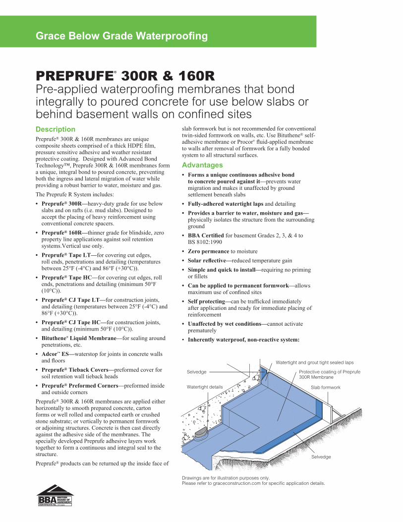
PREPRUFE® 300R & 160RPre-applied waterproofing membranes that bond integrally to poured concrete for use below slabs or behind basement walls on confined sites
Grace Below Grade Waterproofing
slab formwork but is not recommended for conventional twin-sided formwork on walls, etc. Use Bituthene® self-adhesive membrane or Procor® fluid-applied membrane to walls after removal of formwork for a fully bonded system to all structural surfaces.
Advantages• Forms a unique continuous adhesive bond
to concrete poured against it—prevents water migration and makes it unaffected by ground settlement beneath slabs
• Fully-adhered watertight laps and detailing• Provides a barrier to water, moisture and gas—
physically isolates the structure from the surrounding ground
• BBACertified for basement Grades 2, 3, & 4 to BS 8102:1990
• Zero permeance to moisture• Solarreflective—reduced temperature gain• Simple and quick to install—requiring no priming
or fillets• Can be applied to permanent formwork—allows
maximum use of confined sites• Self protecting—can be trafficked immediately
after application and ready for immediate placing of reinforcement
• Unaffected by wet conditions—cannot activate prematurely
• Inherently waterproof, non-reactive system:
DescriptionPreprufe® 300R & 160R membranes are unique composite sheets comprised of a thick HDPE film, pressure sensitive adhesive and weather resistant protective coating. Designed with Advanced Bond Technology™, Preprufe 300R & 160R membranes form a unique, integral bond to poured concrete, preventing both the ingress and lateral migration of water while providing a robust barrier to water, moisture and gas.The Preprufe R System includes:• Preprufe® 300R—heavy-duty grade for use below
slabs and on rafts (i.e. mud slabs). Designed to accept the placing of heavy reinforcement using conventional concrete spacers.
• Preprufe® 160R—thinner grade for blindside, zero property line applications against soil retention systems.Vertical use only.
• Preprufe® Tape LT—for covering cut edges, roll ends, penetrations and detailing (temperatures between 25°F (-4°C) and 86°F (+30°C)).
• Preprufe® Tape HC—for covering cut edges, roll ends, penetrations and detailing (minimum 50°F (10°C)).
• Preprufe® CJ Tape LT—for construction joints, and detailing (temperatures between 25°F (-4°C) and 86°F (+30°C)).
• Preprufe® CJ Tape HC—for construction joints, and detailing (minimum 50°F (10°C)).
• Bituthene® Liquid Membrane—for sealing around penetrations, etc.
• Adcor™ ES—waterstop for joints in concrete walls and floors
• Preprufe® Tieback Covers—preformed cover for soil retention wall tieback heads
• Preprufe® Preformed Corners—preformed inside and outside corners
Preprufe® 300R & 160R membranes are applied either horizontally to smooth prepared concrete, carton forms or well rolled and compacted earth or crushed stone substrate; or vertically to permanent formwork or adjoining structures. Concrete is then cast directly against the adhesive side of the membranes. The specially developed Preprufe adhesive layers work together to form a continuous and integral seal to the structure. Preprufe® products can be returned up the inside face of
Drawings are for illustration purposes only. Please refer to graceconstruction.com for specific application details.
97/3325
Watertight and grout tight sealed laps
Slab formwork
Selvedge
Selvedge Protective coating of Preprufe 300R Membrane
Watertight details
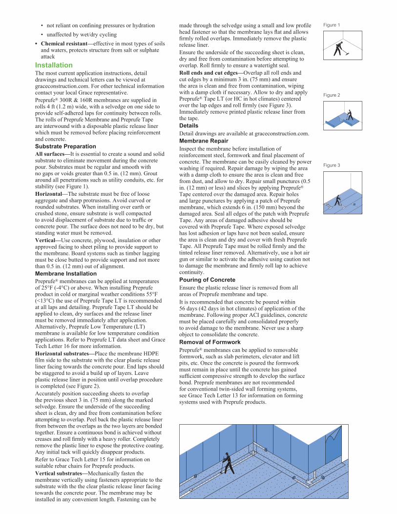
• not reliant on confining pressures or hydration• unaffected by wet/dry cycling
• Chemical resistant—effective in most types of soils and waters, protects structure from salt or sulphate attack
InstallationThe most current application instructions, detail drawings and technical letters can be viewed at graceconstruction.com. For other technical information contact your local Grace representative.Preprufe® 300R & 160R membranes are supplied in rolls 4 ft (1.2 m) wide, with a selvedge on one side to provide self-adhered laps for continuity between rolls. The rolls of Preprufe Membrane and Preprufe Tape are interwound with a disposable plastic release liner which must be removed before placing reinforcement and concrete.Substrate PreparationAll surfaces—It is essential to create a sound and solid substrate to eliminate movement during the concrete pour. Substrates must be regular and smooth with no gaps or voids greater than 0.5 in. (12 mm). Grout around all penetrations such as utility conduits, etc. for stability (see Figure 1).Horizontal—The substrate must be free of loose aggregate and sharp protrusions. Avoid curved or rounded substrates. When installing over earth or crushed stone, ensure substrate is well compacted to avoid displacement of substrate due to traffic or concrete pour. The surface does not need to be dry, but standing water must be removed.Vertical—Use concrete, plywood, insulation or other approved facing to sheet piling to provide support to the membrane. Board systems such as timber lagging must be close butted to provide support and not more than 0.5 in. (12 mm) out of alignment.Membrane InstallationPreprufe® membranes can be applied at temperatures of 25°F (-4°C) or above. When installing Preprufe product in cold or marginal weather conditions 55°F (<13°C) the use of Preprufe Tape LT is recommended at all laps and detailing. Preprufe Tape LT should be applied to clean, dry surfaces and the release liner must be removed immediately after application. Alternatively, Preprufe Low Temperature (LT) membrane is available for low temperature condition applications. Refer to Preprufe LT data sheet and Grace Tech Letter 16 for more information.Horizontal substrates—Place the membrane HDPE film side to the substrate with the clear plastic release liner facing towards the concrete pour. End laps should be staggered to avoid a build up of layers. Leave plastic release liner in position until overlap procedure is completed (see Figure 2). Accurately position succeeding sheets to overlap the previous sheet 3 in. (75 mm) along the marked selvedge. Ensure the underside of the succeeding sheet is clean, dry and free from contamination before attempting to overlap. Peel back the plastic release liner from between the overlaps as the two layers are bonded together. Ensure a continuous bond is achieved without creases and roll firmly with a heavy roller. Completely remove the plastic liner to expose the protective coating. Any initial tack will quickly disappear products.Refer to Grace Tech Letter 15 for information on suitable rebar chairs for Preprufe products.Vertical substrates—Mechanically fasten the membrane vertically using fasteners appropriate to the substrate with the the clear plastic release liner facing towards the concrete pour. The membrane may be installed in any convenient length. Fastening can be
made through the selvedge using a small and low profile head fastener so that the membrane lays flat and allows firmly rolled overlaps. Immediately remove the plastic release liner. Ensure the underside of the succeeding sheet is clean, dry and free from contamination before attempting to overlap. Roll firmly to ensure a watertight seal. Roll ends and cut edges—Overlap all roll ends and cut edges by a minimum 3 in. (75 mm) and ensure the area is clean and free from contamination, wiping with a damp cloth if necessary. Allow to dry and apply Preprufe® Tape LT (or HC in hot climates) centered over the lap edges and roll firmly (see Figure 3). Immediately remove printed plastic release liner from the tape.DetailsDetail drawings are available at graceconstruction.com.Membrane RepairInspect the membrane before installation of reinforcement steel, formwork and final placement of concrete. The membrane can be easily cleaned by power washing if required. Repair damage by wiping the area with a damp cloth to ensure the area is clean and free from dust, and allow to dry. Repair small punctures (0.5 in. (12 mm) or less) and slices by applying Preprufe® Tape centered over the damaged area. Repair holes and large punctures by applying a patch of Preprufe membrane, which extends 6 in. (150 mm) beyond the damaged area. Seal all edges of the patch with Preprufe Tape. Any areas of damaged adhesive should be covered with Preprufe Tape. Where exposed selvedge has lost adhesion or laps have not been sealed, ensure the area is clean and dry and cover with fresh Preprufe Tape. All Preprufe Tape must be rolled firmly and the tinted release liner removed. Alternatively, use a hot air gun or similar to activate the adhesive using caution not to damage the membrane and firmly roll lap to achieve continuity.Pouring of ConcreteEnsure the plastic release liner is removed from all areas of Preprufe membrane and tape.It is recommended that concrete be poured within 56 days (42 days in hot climates) of application of the membrane. Following proper ACI guidelines, concrete must be placed carefully and consolidated properly to avoid damage to the membrane. Never use a sharp object to consolidate the concrete.Removal of FormworkPreprufe® membranes can be applied to removable formwork, such as slab perimeters, elevator and lift pits, etc. Once the concrete is poured the formwork must remain in place until the concrete has gained sufficient compressive strength to develop the surface bond. Preprufe membranes are not recommended for conventional twin-sided wall forming systems, see Grace Tech Letter 13 for information on forming systems used with Preprufe products.
Figure 1
Figure 2
Figure 3
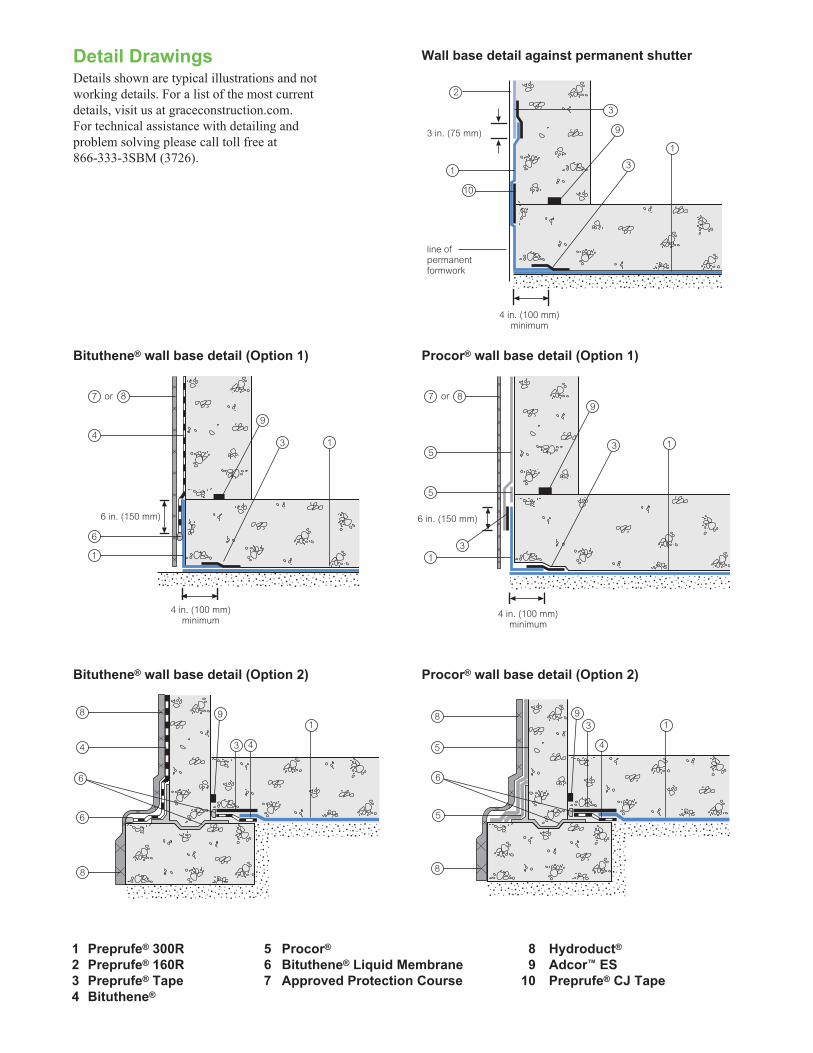
1 Preprufe® 300R 5 Procor® 8 Hydroduct®
2 Preprufe® 160R 6 Bituthene® Liquid Membrane 9 Adcor™ ES3 Preprufe® Tape 7 Approved Protection Course 10 Preprufe® CJ Tape4 Bituthene®
1
1
3 4
13
4
Wall base detail against permanent shutter
Bituthene® wall base detail (Option 1) Procor® wall base detail (Option 1)
Bituthene® wall base detail (Option 2) Procor® wall base detail (Option 2)
line of permanent formwork
4 in. (100 mm) minimum
6 in. (150 mm) 6 in. (150 mm)
3 in. (75 mm)
8
8
6
4
8
8
5
8or7
6
4
1
3
2
1
Detail DrawingsDetails shown are typical illustrations and not working details. For a list of the most current details, visit us at graceconstruction.com. For technical assistance with detailing and problem solving please call toll free at 866-333-3SBM (3726).
3
1
3
1
8or7
5
5
1
3
3
4 in. (100 mm) minimum
4 in. (100 mm) minimum
9
10
9
5
9
6
9
6
9
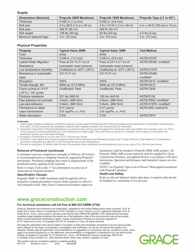
www.graceconstruction.comFor technical assistance call toll free at 866-333-3SBM (3726)Preprufe, Bituthene and Hydroduct are trademarks, registered in the United States and/or other countries, of W. R. Grace & Co.-Conn. Adcor is a trademark of W.R. Grace& Co.-Conn. Procor is a U.S. registered trademark of W. R. Grace & Co. -Conn., and is used in Canada under license from PROCOR LIMITED. This trademark list has been compiled using available published information as of the publication date of this brochure and may not accurately reflect current trademark ownership or status. Grace Construction Products is a business segment of W. R. Grace & Co.-Conn. © Copyright 2014 W. R. Grace& Co.-Conn. All rights reserved.We hope the information here will be helpful. It is based on data and knowledge considered to be true and accurate and is offered for the users’ consideration, investigation and verification, but we do not warrant the results to be obtained. Please read all statements, recommendations or suggestions in conjunction with our conditions of sale, which apply to all goods supplied by us. No statement, recommendation or suggestion is intended for any use which would infringe any patent or copyright. W. R. Grace & Co.–Conn., 62 Whittemore Avenue, Cambridge, MA 02140. In Canada, Grace Canada, Inc., 294 Clements Road, West, Ajax, Ontario, Canada L1S 3C6.This product may be covered by patents or patents pending. PF-111I Printed in U.S.A. 12/14 GCS/PDF
Physical Properties Property Typical Value 300R Typical Value 160R Test Method Color white white Thickness 0.046 in. (1.2 mm) 0.032 in. (0.8 mm) ASTM D3767 Lateral Water Migration Pass at 231 ft (71 m) of Pass at 231 ft (71 m) of ASTM D5385, modified1 Resistance hydrostatic head pressure hydrostatic head pressure Low temperature flexibility Unaffected at -20°F (-29°C) Unaffected at -20°F (-29°C) ASTM D1970 Resistance to hydrostatic 231 ft (71 m) 231 ft (71 m) ASTM D5385, head modified2
Elongation 500% 500% ASTM D412, modified3
Tensile strength, film 4000 psi (27.6 MPa) 4000 psi (27.6 MPa) ASTM D412 Crack cycling at -9.4°F Unaffected, Pass Unaffected, Pass ASTM C836 (-23°C), 100 cycles Puncture resistance 221 lbs (990 N) 100 lbs (445 N) ASTM E154 Peel adhesion to concrete 5 lbs/in. (880 N/m) 5 lbs/in. (880 N/m) ASTM D903, modified4
Lap peel adhesion 5 lbs/in. (880 N/m) 5 lbs/in. (880 N/m) ASTM D1876, modified5
Permeance to water 0.01 perms 0.01 perms ASTM E96, method B vapor transmission (0.6 ng/(Pa x s x m2)) (0.6 ng/(Pa x s x m2)) Water absorption 0.5% 0.5% ASTM D570
Footnotes:1. Lateral water migration resistance is tested by casting concrete against membrane with a hole and subjecting the membrane to hydrostatic head pressure
with water. The test measures the resistance of lateral water migration between the concrete and the membrane.2. Hydrostatic head tests of Preprufe Membranes are performed by casting concrete against the membrane with a lap. Before the concrete cures, a 0.125 in.
(3 mm) spacer is inserted perpendicular to the membrane to create a gap. The cured block is placed in a chamber where water is introduced to the membrane surface up to the head indicated.
3. Elongation of membrane is run at a rate of 2 in. (50 mm) per minute.4. Concrete is cast against the protective coating surface of the membrane and allowed to properly dry (7 days minimum). Peel adhesion of membrane to
concrete is measured at a rate of 2 in. (50 mm) per minute at room temperature.5. The test is conducted 15 minutes after the lap is formed (per Grace published recommendations) and run at a rate of 2 in. (50 mm) per minute.
Supply Dimensions (Nominal) Preprufe 300R Membrane Preprufe 160R Membrane Preprufe Tape (LT or HC*) Thickness 0.046 in. (1.2 mm) 0.032 in. (0.8 mm) Roll size 4 ft x 98 ft (1.2 m x 30 m) 4 ft x 115 ft (1.2 m x 35 m) 4 in. x 49 ft (100 mm x 15 m) Roll area 392 ft2 (36 m2) 460 ft2 (42 m2) Roll weight 108 lbs (50 kg) 92 lbs (42 kg) 4.3 lbs (2 kg) Minimum side/end laps 3 in. (75 mm) 3 in. (75 mm) 3 in. (75 mm)
Removal of Formwork (continued)A minimum concrete compressive strength of 3000 psi (20 N/mm2) is recommended prior to stripping formwork supporting Preprufe® membranes. Premature stripping may result in displacement of the membrane and/or spalling of the concrete. Refer to Grace Tech Letter 17 for information on removal of formwork for Preprufe products.Specification ClausesPreprufe 300R® or 160R membrane shall be applied with its protective coating presented to receive fresh concrete to which it will integrally bond. Only Grace Construction Products approved
membranes shall be bonded to Preprufe 300R/160R product. All Preprufe 300R/160R system materials shall be supplied by Grace Construction Products, and applied strictly in accordance with their instructions. Specimen performance and formatted clauses are also available.NOTE: Use Preprufe Tape to tie-in Procor® fluid-applied membrane with Preprufe® products.Health and SafetyRefer to relevant Material Safety data sheet. Complete rolls should be handled by a minimum of two persons.
1. Product Name• Bitutheneª Waterproofing Systems• Hydroductª Drainage Composites
2. ManufacturerGrace Construction Products62 Whittemore AvenueCambridge, MA 02140
(866) 333-3SBM (3726)Fax: (617) 498-4311www.graceconstruction.com
3. Product Description
BASIC USE
Bitutheneª waterproofing systems andHydroductª drainage composites are used inpositive-side waterproofing applications overconcrete, masonry and wood surfaces. Theyare used in new construction and retrofit appli-cations. Typical applications include founda-tion walls, tunnels, earth sheltered structures,and split slab construction such as plaza areasand parking decks. Interior uses includemechanical rooms, laboratories and kitchens.
COMPOSITION & MATERIALS
The Bituthene waterproofing systems consistof several waterproofing membranes andcompatible accessory products and arecomplemented by the use of the appropriateHydroduct drainage composite.
The Bituthene membranes are available inrolls, interwound with a disposable siliconetreated release sheet. The volatile organiccompound (VOC) content of all Bituthenemembranes is 0 g/L.
Bituthene System 4000 WaterproofingMembrane is a factory made composite witha thickness of 0.060" (1.5 mm) consisting of0.004" (0.1 mm) of cross-laminated poly-ethylene film and 0.056" (1.4 mm) of self-adhesive rubberized asphalt. It is specificallyformulated for use with the Bituthene System4000 Surface Conditioner and compatibleaccessory products.
Bituthene System 4000 Surface Conditioneris a water based surface conditionerspecifically formulated to prepare concrete,masonry and wood surfaces for the System
4000 Waterproofing Membrane. Its VOC con-tent is 125 g/L.
Bituthene 3000 and Bituthene LowTemperature Membranes are factory madecomposites with a thickness of 0.060" (1.5 mm). These products consist of 0.056" (1.4 mm) of self-adhesive rubberized asphaltand 0.004" (0.1 mm) of cross-laminated, highdensity polyethylene film.
Hydroduct drainage composites consist ofdimpled, high impact polystyrene cores and fil-ter fabrics designed to provide positivedrainage and membrane protection. The VOCcontent of all Hydroduct products is 0 g/L.
Hydroduct 220 Drainage Composite is usedfor vertical applications over Bituthene water-proofing membranes.
Hydroduct 660 Drainage Composite is usedfor all horizontal applications.
Hydroduct 200 is intended for areas whichare not waterproofed. Hydroduct 225Drainage Composite incorporates a moldedpolyvinyl chloride core and is intended forareas requiring heat or hydrocarbon resist-ance.
COMPATIBILITY
Apply waterproofing membrane directly tostructural surfaces. Bituthene membranes canbe used over EPS wall forming systems if theadditional guidelines in Technical Letter 18,“Insulated Wall Forming Systems,” are fol-lowed.
Bituthene membranes are compatible withaged asphalt and coal tar products.
Bituthene membranes are incompatiblewith creosote, pentachlorophenol, linseed oiland materials containing polysulfide polymer.
The rubberized asphalt component ofBituthene membranes is not compatible withflexible PVC or rubber sheet membranes.
Do not apply Bituthene membranes overmaterials containing petroleum solvents, fuelsor oils. Joint sealants containing solvents mustbe fully cured prior to Bituthene membraneapplication. Refer to Technical Letter 10,“Chemical Compatibility with OtherMaterials.”
Bituthene membranes are compatible withappropriate Hydroduct drainage composites.
Bituthene membranes are not compatiblewith certain types of prefabricated drainage systems that damage waterproofing mem-branes when exposed to soil pressures.
ACCESSORY MATERIALS
Architectural and Industrial Maintenance
Regulations limit the VOC content in productsclassified as Architectural Coatings. Refer toTechnical Letters on manufacturer’s websitefor the most current list of allowable limits.
Bituthene Primer WP-3000 is a water basedlatex primer used to prime all concrete,masonry and wood surfaces. Its VOC contentis 110 g/L.
Bituthene Primer B2 is a black, rubber basedprimer in solvent used to prime all concrete,masonry and wood surfaces. In addition, itspatented formulation promotes the adhesionof Bituthene membranes to green concreteand damp surfaces. Its VOC content is 440g/L.
Bituthene Deck Prepª Surface Treatment isa low viscosity, 2-component, asphalt-modi-fied coating used to smooth and level roughdecks prior to installing the Bituthene water-proofing membrane. Its VOC content is 10 g/L.
Bituthene Liquid Membrane is a 2-compo-nent, cold applied trowel grade waterproof-ing material used to flash corners, form filletsand detail hard-to-reach areas. Its VOC con-tent is 10 g/L.
Bituthene Mastic is a rubberized asphaltbased mastic used to seal membrane terminations. Its VOC content is 200 g/L.
Hydroduct Tape is a 2-sided, highly aggres-sive adhesive tape that is specially formulat-ed to adhere Hydroduct drainage compos-ites or expanded or extruded polystyreneprotection board to the membrane. Its VOCcontent is 61 g/L.
LIMITATIONS
Do not apply Bituthene membranes in areaswhere they will be permanently exposed tosunlight, weather or traffic.
Bituthene membranes are not recom-mended as pond liners or as tank linersexcept when installed between 2 concreteslabs.
Bituthene strips over joints in T-beam struc-tures will not provide complete waterproof-ing. For these structures, 9" (225 mm) stripsover properly cured and sealed joints, fol-lowed by membrane coverage over theentire surface, are required for a completewaterproofing system.
Bituthene membranes are not intended tobe used as a roofing underlayment or flashingmaterial.
Use of tile set in thinset mortar is not rec-ommended on surfaces waterproofed withBituthene membranes unless approved bythinset mortar manufacturer.
SHEET WATERPROOFING 07 13 00
Grace Construction Products
®
SPEC-DATAª and MANU-SPECª are registered trademarks of Reed Elsevier Inc. The ten part SPEC-DATA format conforms to the editorial style of The Construction Specifications Institute and is used with their permission. The manufacturer is responsible for technical accuracy. ©2007 Reed Construction Data. All Rights Reserved.
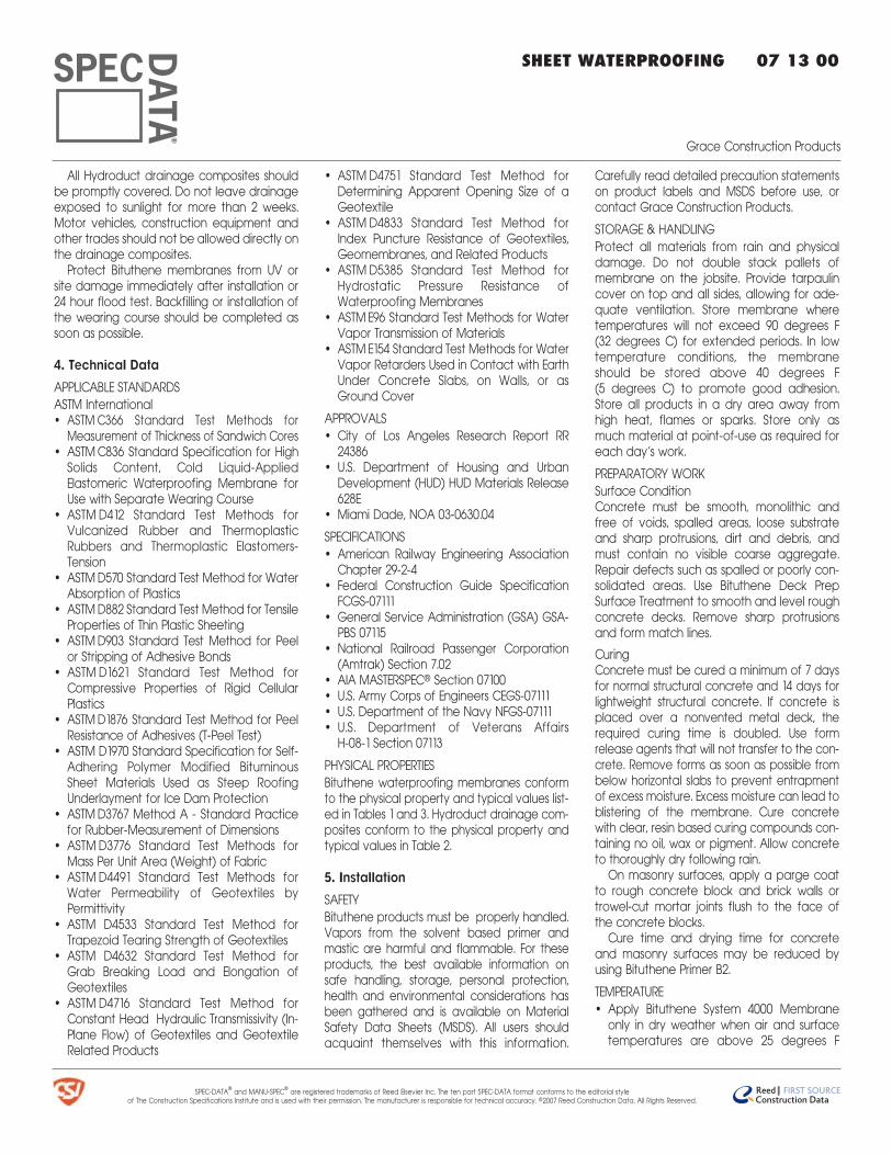
SPEC-DATAª and MANU-SPECª are registered trademarks of Reed Elsevier Inc. The ten part SPEC-DATA format conforms to the editorial style of The Construction Specifications Institute and is used with their permission. The manufacturer is responsible for technical accuracy. ©2007 Reed Construction Data. All Rights Reserved.
All Hydroduct drainage composites shouldbe promptly covered. Do not leave drainageexposed to sunlight for more than 2 weeks.Motor vehicles, construction equipment andother trades should not be allowed directly onthe drainage composites.
Protect Bituthene membranes from UV orsite damage immediately after installation or24 hour flood test. Backfilling or installation ofthe wearing course should be completed assoon as possible.
4. Technical Data
APPLICABLE STANDARDS
ASTM International• ASTM C366 Standard Test Methods for
Measurement of Thickness of Sandwich Cores• ASTM C836 Standard Specification for High
Solids Content, Cold Liquid-AppliedElastomeric Waterproofing Membrane forUse with Separate Wearing Course
• ASTM D412 Standard Test Methods forVulcanized Rubber and ThermoplasticRubbers and Thermoplastic Elastomers-Tension
• ASTM D570 Standard Test Method for WaterAbsorption of Plastics
• ASTM D882 Standard Test Method for TensileProperties of Thin Plastic Sheeting
• ASTM D903 Standard Test Method for Peelor Stripping of Adhesive Bonds
• ASTM D1621 Standard Test Method forCompressive Properties of Rigid CellularPlastics
• ASTM D1876 Standard Test Method for PeelResistance of Adhesives (T-Peel Test)
• ASTM D1970 Standard Specification for Self-Adhering Polymer Modified BituminousSheet Materials Used as Steep RoofingUnderlayment for Ice Dam Protection
• ASTM D3767 Method A - Standard Practicefor Rubber-Measurement of Dimensions
• ASTM D3776 Standard Test Methods forMass Per Unit Area (Weight) of Fabric
• ASTM D4491 Standard Test Methods forWater Permeability of Geotextiles byPermittivity
• ASTM D4533 Standard Test Method forTrapezoid Tearing Strength of Geotextiles
• ASTM D4632 Standard Test Method forGrab Breaking Load and Elongation ofGeotextiles
• ASTM D4716 Standard Test Method forConstant Head Hydraulic Transmissivity (In-Plane Flow) of Geotextiles and GeotextileRelated Products
• ASTM D4751 Standard Test Method forDetermining Apparent Opening Size of aGeotextile
• ASTM D4833 Standard Test Method forIndex Puncture Resistance of Geotextiles,Geomembranes, and Related Products
• ASTM D5385 Standard Test Method forHydrostatic Pressure Resistance ofWaterproofing Membranes
• ASTM E96 Standard Test Methods for WaterVapor Transmission of Materials
• ASTM E154 Standard Test Methods for WaterVapor Retarders Used in Contact with EarthUnder Concrete Slabs, on Walls, or asGround Cover
APPROVALS
• City of Los Angeles Research Report RR24386
• U.S. Department of Housing and UrbanDevelopment (HUD) HUD Materials Release628E
• Miami Dade, NOA 03-0630.04
SPECIFICATIONS
• American Railway Engineering AssociationChapter 29-2-4
• Federal Construction Guide SpecificationFCGS-07111
• General Service Administration (GSA) GSA-PBS 07115
• National Railroad Passenger Corporation(Amtrak) Section 7.02
• AIA MASTERSPECª Section 07100• U.S. Army Corps of Engineers CEGS-07111• U.S. Department of the Navy NFGS-07111• U.S. Department of Veterans Affairs
H-08-1 Section 07113
PHYSICAL PROPERTIES
Bituthene waterproofing membranes conformto the physical property and typical values list-ed in Tables 1 and 3. Hydroduct drainage com-posites conform to the physical property andtypical values in Table 2.
5. Installation
SAFETY
Bituthene products must be properly handled.Vapors from the solvent based primer andmastic are harmful and flammable. For theseproducts, the best available information onsafe handling, storage, personal protection,health and environmental considerations hasbeen gathered and is available on MaterialSafety Data Sheets (MSDS). All users shouldacquaint themselves with this information.
Carefully read detailed precaution statementson product labels and MSDS before use, orcontact Grace Construction Products.
STORAGE & HANDLING
Protect all materials from rain and physicaldamage. Do not double stack pallets ofmembrane on the jobsite. Provide tarpaulincover on top and all sides, allowing for ade-quate ventilation. Store membrane wheretemperatures will not exceed 90 degrees F (32 degrees C) for extended periods. In lowtemperature conditions, the membraneshould be stored above 40 degrees F (5 degrees C) to promote good adhesion.Store all products in a dry area away fromhigh heat, flames or sparks. Store only asmuch material at point-of-use as required foreach day’s work.
PREPARATORY WORK
Surface ConditionConcrete must be smooth, monolithic andfree of voids, spalled areas, loose substrateand sharp protrusions, dirt and debris, andmust contain no visible coarse aggregate.Repair defects such as spalled or poorly con-solidated areas. Use Bituthene Deck PrepSurface Treatment to smooth and level roughconcrete decks. Remove sharp protrusionsand form match lines.
CuringConcrete must be cured a minimum of 7 daysfor normal structural concrete and 14 days forlightweight structural concrete. If concrete isplaced over a nonvented metal deck, therequired curing time is doubled. Use formrelease agents that will not transfer to the con-crete. Remove forms as soon as possible frombelow horizontal slabs to prevent entrapmentof excess moisture. Excess moisture can lead toblistering of the membrane. Cure concretewith clear, resin based curing compounds con-taining no oil, wax or pigment. Allow concreteto thoroughly dry following rain.
On masonry surfaces, apply a parge coatto rough concrete block and brick walls ortrowel-cut mortar joints flush to the face ofthe concrete blocks.
Cure time and drying time for concreteand masonry surfaces may be reduced byusing Bituthene Primer B2.
TEMPERATURE
• Apply Bituthene System 4000 Membraneonly in dry weather when air and surfacetemperatures are above 25 degrees F
SHEET WATERPROOFING 07 13 00
Grace Construction Products
®
SPEC-DATAª and MANU-SPECª are registered trademarks of Reed Elsevier Inc. The ten part SPEC-DATA format conforms to the editorial style of The Construction Specifications Institute and is used with their permission. The manufacturer is responsible for technical accuracy. ©2007 Reed Construction Data. All Rights Reserved.
(-4 degrees C)• Apply Bituthene 3000 Membrane only in dry
weather when air and surface temperaturesare above 40 degrees F (5 degrees C)
• Bituthene Low Temperature Membranecan be used at temperatures above25 degrees F (-4 degrees C) and up to60 degrees F (16 degrees C)
• Cover the membrane immediately in tem-peratures above 77 degrees F (25 degreesC) to reduce potential for blistering
• Apply Bituthene System 4000 SurfaceConditioner and other accessory productsnot listed below in dry weather above25 degrees F (-4 degrees C)
• Apply Bituthene Primer WP-3000 in dryweather above 40 degrees F (5 degrees C)
• Do not apply products to frozen concrete
APPLICATION
Surface ConditionerBituthene System 4000 Surface Conditioner issupplied ready to use. Do not dilute with wateror solvents. Spray surface conditioner uniformlyto substrate at a rate of 300 ft2/gal (7.5 m2/L).Use appropriate sprayer and nozzle.
Allow surface conditioner to dry completelyand thoroughly prior to membrane application.The surface conditioner is considered dry whenthe substrate returns to its original color. To testfor dryness, rub small conditioned area by
hand. Wet conditioner will ball up under the fin-gertips. Let dry until conditioner cannot berubbed off. If conditioned areas are not covered that day, recondition the area if thereis significant dust or dirt contamination.
PrimerApply Bituthene Primer WP-3000 by spray orroller at a coverage rate of 500 - 600 ft2/gal(12 - 15 m2/L). Allow to dry 1 hour or until con-crete returns to original color.
Apply Bituthene Primer B2 by lamb’s woolroller at a coverage rate of 250 - 350 ft2/gal (6- 8 m2/L). Allow primer to dry 1 hour or until tack-free. Dry time may be longer in cold tempera-tures.
Reprime areas if contaminated by dust. Ifthe work area is dusty, apply membrane assoon as the primer is dry.
Surfaces treated with Deck Prep SurfaceTreatment do not require conditioning or prim-ing. Metal does not require priming but mustbe clean, dry and free of loose paint, rust orother contaminants. Use Bituthene Primer B2 fordamp or green substrates. Do not applyprimer or surface conditioner to membrane.
CornersThe treatment of corners varies depending onthe location of the corner.
At wall-to-footing inside corners:• Option 1 - Apply membrane to within 1"
(25 mm) of base of wall. Treat the insidecorner by installing a 3/4" (19 mm) fillet of Bituthene Liquid Membrane. Extend liquidmembrane at least 3" (75 mm) onto wallmembrane
• Option 2 - Treat the inside corner by installing a 3/4" (19 mm) fillet of BitutheneLiquid Membrane. Apply 12" (300 mm) widestrip of membrane centered over fillet.Apply wall membrane over inside cornerand extend 6" (150 mm) onto footing. Apply1" (25 mm) wide troweling of BitutheneMastic or Bituthene Liquid Membrane overall terminations and seams within 12"(300 mm) of corner
At footings where the elevation of the floorslab is 6" (150 mm) or more above the footing,treat the inside corner either by one of theabove methods or terminate the membraneat the base of the wall. Seal the terminationwith Bituthene Mastic or Bituthene LiquidMembrane.
At plaza deck-to-wall inside corners:• Option 1 - Apply membrane on wall and
deck to within 1" (25 mm) of corner. Treatthe inside corner by installing a 3/4" (19 mm) fillet of Bituthene Liquid Membrane.Extend Bituthene Liquid Membrane at least3" (75 mm) onto deck membrane and 3"(75 mm) onto wall membrane. Terminate
SHEET WATERPROOFING 07 13 00
Grace Construction Products
®
TABLE 1 PHYSICAL PROPERTIES OF BITUTHENE MEMBRANES
Property & Test Method Bituthene System 4000 Membrane Bituthene 3000 Membrane Bituthene LowTemperature Membrane
Color Gray-black Dark gray-black Gray-black
Thickness, ASTM D3767, Method A 0.060" (1.5 mm) nominal 0.060" (1.5 mm) nominal 0.060" (1.5 mm) nominal
Low temperature flexibility, ASTM D1970 Unaffected at -45°F (-43°C) Unaffected at -25°F (-32°C) Unaffected at -45°F (-43°C)
Resistance to hydrostatic head, ASTM D5385 231' (70 m) min 200' (60 m) min 200' (61 m) min
Lap adhesion at minimum application temperature, 5.0 lb/in (880 N/m) 4.0 lb/in (700 N/m) 5.0 lb/in (880 N/m)width, ASTM D1876, Modified
Tensile strength, membrane, ASTM D412 (Die C), 325 psi (2240 kPa) min 325 psi (2240 kPa) min 325 psi (2240 kPa) minModified
Tensile strength, film, ASTM D882, Modified 5000 psi (34.5 MPa) min 5000 psi (34.5 MPa) min 5000 psi (34.5 MPa) min
Elongation, ultimate failure of rubberized asphalt, 300% min 300% min 300% minASTM D412, Modified
Cracking cycling, 100 cycles, ASTM D836 Unaffected at -25°F (-32°C) Unaffected at -25°F (-32°C) Unaffected at -25°F (-32°C)
Peel strength, width, ASTM D903, Modified 9.0 lb/in (1576 N/m) 9.0 lb/in (1576 N/m) 9.0 lb/in (1576 N/m)
Puncture resistance, membrane, ASTM E154 50 lb (222 N) min 50 lb (222 N) min 50 lb (222 N) min
Permeance, maximum, ASTM E96 Water Method 0.05 perms (2.9 ng/(Pa × s × m2)) 0.05 perms (2.9 ng/(Pa × s × m2)) 0.05 perms (2.9 ng/(Pa × s × m2))
Water absorption, 72 hr, ASTM D570 0.1% max 0.1% max 0.1% max
top of membrane wall flashing withBituthene Mastic, Bituthene LiquidMembrane or termination bar
• Option 2 - Apply membrane on deck towithin 1" (25 mm) of corner. Treat the insidecorner by installing a 3/4" (19 mm) fillet of Bituthene Liquid Membrane. ExtendBituthene Liquid Membrane at least 3" (75mm) onto wall and membrane
• Option 3 - Apply membrane on deck towithin 1" (25 mm) of corner. Treat the insidecorner by installing a 3/4" (19 mm) fillet ofBituthene Liquid Membrane. Apply mem-brane flashing sheet on wall, over fillet and6" (150 mm) onto deck membrane. Apply 1"(25 mm) wide troweling of Bituthene Masticor Bituthene Liquid Membrane over all ter-minations and seams within 12" (300 mm) ofcorner. Terminate top of membrane wallflashing with Bituthene Mastic, BitutheneLiquid Membrane or termination bar
In planters, reflecting pools and fountains,apply membrane on wall and deck to within1" (25 mm) of corner. Treat the inside corner byinstalling a 3/4" (19 mm) fillet of BitutheneLiquid Membrane. Extend Bituthene LiquidMembrane at least 3" (75 mm) onto deckmembrane and 3" (75 mm) onto wall mem-brane. Terminate top of wall membrane withBituthene Liquid Membrane or terminationbar.
For wall to wall inside corner, apply 12" (300 mm) membrane strip centered on corner.
Press membrane tightly into corner to ensure fullcontact. Cover the treated corner with a fullsheet of membrane to ensure 2-ply coverage.
For outside corners, apply 12" (300 mm)membrane strip centered on corner. Coverthe treated corner with a full sheet of mem-brane to ensure 2-ply coverage.
JointsProperly seal all joints with waterstop, joint fillerand sealant as required. Bituthene mem-branes are not intended to function as theprimary joint seal. Allow sealant to fully cure.Prestrip all slabs and wall cracks over 1/16" (1.6 mm) wide and all construction and controljoints with 9" (225 mm) wide membrane.
DrainsAt drains, apply a collar of membrane whichextends 6" (150 mm) beyond the drain open-ing. Apply full coverage of membrane overthe collar. Cut out the drain opening so themembrane extends under the clamping ring.Place a bead of Bituthene Mastic or BitutheneLiquid Membrane between the membraneand clamping ring. An alternate method is toapply Bituthene Liquid Membrane 0.090" (2.3mm) thick so that it extends under the clamp-ing ring and overlaps the deck membrane atleast 3" (75 mm). Install clamping ring afterBituthene Liquid Membrane has cured.
Application to Horizontal SurfacesApply membrane from the low point to thehigh point so that laps shed water. Overlap all
seams at least 2 1/2" (64 mm). Stagger all endlaps.
Roll the entire membrane firmly and com-pletely as soon as possible. Use a linoleumroller or standard water-filled garden rollerless than 30" (762 mm) wide, weighing a mini-mum of 75 lb (34 kg) when filled. Cover theface of the roller with a resilient material suchas a 1/2" (13 mm) plastic foam or 2 wraps ofindoor/outdoor carpet to allow the mem-brane to fully contact the primed substrate.
Seal all T-joints and membrane terminationswith Bituthene Mastic or Bituthene LiquidMembrane at the end of the day.
For required testing of horizontal applica-tions, see Flood Testing.
Application to Vertical SurfacesApply membrane in lengths up to 8' (2 m).Overlap all seams 2 1/2" (64 mm) minimum. On higher walls, apply membrane in 2 or moresections with the upper overlapping the lowerby at least 2 1/2" (64 mm). Roll membrane witha hand roller.
Terminate the membrane at grade level.Press the membrane firmly to the wall with thebutt end of a hardwood tool such as ahammer handle, or secure into a reglet. A ter-mination bar may be used to secure the toptermination. Failure to use heavy pressure atterminations can result in a poor seal.
Terminate the membrane at the base ofthe wall if the bottom of the interior floor slabis at least 6" (150 mm) above the
SHEET WATERPROOFING 07 13 00
Grace Construction Products
®
SPEC-DATAª and MANU-SPECª are registered trademarks of Reed Elsevier Inc. The ten part SPEC-DATA format conforms to the editorial style of The Construction Specifications Institute and is used with their permission. The manufacturer is responsible for technical accuracy. ©2007 Reed Construction Data. All Rights Reserved.
TABLE 2 PHYSICAL PROPERTIES OF HYDRODUCT DRAINAGE COMPOSITES
Property & Test Method Hydroduct 220 Hydroduct 660 Hydroduct 200 Hydroduct 225
Drain core
Thickness, ASTM C366-B 0.433" (11 mm) 0.433" (11 mm) 0.433" (11 mm) 0.433" (11 mm)
Compressive strength, ASTM D1621 (modified) 15,000 psf (732 kN/m2) 21,000 psf (1025 kN/m2) 15,000 psf (732 kN/m2) 21,000 psf (1025 kN/m2)
Flow, 1.0 gradient, 37.9 kPa load, ASTM D4716 16 gal/min/ft 16 gal/min/ft 16 gal/min/ft 16 gal/min/ft
(0.003 L/min/m) (0.003 L/min/m) (0.003 L/min/m) (0.003 L/min/m)
Filter fabric
Apparent opening size, ASTM D4751 100 US sieve 100 US sieve 100 US sieve 40 US sieve
(150 micron) (150 micron) (150 micron) (380 micron)
Permittivity, ASTM D4491 150 gal/min/ft2 80 gal/min/ft2 150 gal/min/ft2 100 gal/min/ft2
(6110 L/min/m2) (3250 L/min/m2) (6110 L/min/m2) (4074 L/min/m2)
Tensile strength, ASTM D4632 110 lb (485 N) 230 lb (1020 N) 110 lb (485 N) 290 lb (1291 N)
Weight, ASTM D3776 4.0 oz/yd2 (136 N/m2) 8.0 oz/yd2 (270 g/m2) 4.0 oz/yd2 (136 g/m2) 6.0 oz/yd2 (203 g/m2)
Mullen Burst, ASTM D3786 215 psi (1480 kPa) 690 psi (4753 kPa) 215 psi (1430 kPa) 480 psi (3304 kPa)
Puncture, ASTM D4833 65 lb (285 N) 162 lb (720 N) 65 lb (285 N) 105 lb (720 N)
footing. Otherwise, use appropriate insidecorner detail where the wall and footingmeet. Seal all laps within 12" (300 mm) of allcorners with a troweling of mastic. Apply atroweled bead of Bituthene Mastic orBituthene Liquid Membrane to all vertical andhorizontal terminations at the end of eachworkday.
Protrusions and PenetrationsApply membrane to within 1" (25 mm) of thebase of the protrusion. Apply Liquid Membrane0.090" (2.3 mm) thick around the protrusion.Extend Bituthene Liquid Membrane over thesheet membrane at least 3" (75 mm) and upthe protrusion to just below the finished heightof the wearing course (for horizontal applica-tions) or for a minimum of 6" (150 mm) for ver-tical applications.
FLOOD TESTING
Flood test all horizontal applications with aminimum 2" (50 mm) head of water for 24hours. Mark any leaks and repair when themembrane is dry. Before flood testing, be surethe structure will withstand the dead load of the water. For well-sloped decks, segment theflood test to avoid deep water near drains.
Conduct the flood test 1 day after com-pleting the application of Bituthene water-proofing system. Immediately after flood testis completed, and all necessary repairs made,install Hydroduct 660 Drainage Composite toprotect the Bituthene membrane from trafficand other trades.
MEMBRANE REPAIR
Patch tears and inadequately lapped seamswith membrane. Slit fishmouths and repair witha patch extending 6" (150 mm) in all directionsfrom the slit and seal edges of the patch withBituthene Mastic. Inspect the membrane thor-oughly before covering and make any repairs.
PROTECTION
Protection of MembraneProtect Bituthene membranes to avoid dam-age from other trades’ construction materialsor backfill. Place protection immediately in tem-peratures above 77 degrees F (25 degrees C) toreduce potential for blistering.
On horizontal applications, use Hydroduct660 Drainage Composite for protection.Adhere as necessary to membrane withHydroduct Tape.
Alternate methods are to use 1/8" or 1/4" (3 or 6 mm) asphaltic hardboard. When rein-forced concrete slabs are placed over the
membrane, use Hydroduct 660 DrainageComposite or 1/4" (6 mm) hardboard or 2 lay-ers of 1/8" (3 mm) hardboard.
On vertical applications, use Hydroduct 220Drainage Composite. Adhere Hydroduct 220 tomembrane with Hydroduct Tape. Alternative protection methods are to use 1" (25 mm)expanded polystyrene or 1/4" (6 mm) extruded polystyrene that has a minimumcompressive strength of 10 lb/in2 (69 kN/m2).
If 1/4" (6 mm) extruded polystyrene protec-tion board is used, backfill should not containsharp rock or aggregate over 2" (50 mm) indiameter. Adhere polystyrene protectionboard with Hydroduct Tape or compatibleadhesive.
Cover any exposed Bituthene membranewith weather resistant flashing such as cop-per, aluminum or neoprene. Install Hydroduct660 Drainage Composite or alternate protec-tion the same day the membrane is appliedor immediately after a 24 hour flood test. Nowaiting before backfill or application of wear-ing course is necessary.
Placement of BackfillUse care during backfill operation to avoiddamage to waterproofing and drainage sys-tem. Follow generally accepted practice forbackfill and compaction. Backfill should beadded in 6" - 12" (150 - 300 mm) lifts. Forbermed areas that cannot be fully com-pacted, a termination bar is recommendedacross the top termination of the membrane.
In general, backfill or the final wearingcourse should be placed as soon as possibleafter installation of the membrane.
Placement of Reinforcing SteelWhen placing reinforcing steel over properlyprotected membrane, use concrete bar sup-ports (dobies) or chairs with plastic tips orrolled feet to prevent damage from sharpedges. Use special care when using wiremesh, especially if the mesh is curled.
6. Availability & Cost
AVAILABILITY
A network of distributors carries Bituthene water-proofing systems and Hydroduct drainage com-posite products for delivery to project sites.
COST
Bituthene waterproofing systems andHydroduct drainage composites are compet-itively priced. For specific information, contacta local distributor or a Grace Construction
Products representative.
7. WarrantyFive year material warranties coveringBituthene and Hydroduct products are avail-able upon request. Contact the manufactur-er for further information.
8. MaintenanceNone required, if installed in accordance withmanufacturer’s recommendations.
9. Technical ServicesSupport is provided by full-time, technicallytrained Grace representatives and technicalservice personnel, backed by a centralresearch and development staff.
10. Filing Systems• Reed First Source• Additional product information is available
from the manufacturer.
SHEET WATERPROOFING 07 13 00
Grace Construction Products
®
SPEC-DATAª and MANU-SPECª are registered trademarks of Reed Elsevier Inc. The ten part SPEC-DATA format conforms to the editorial style of The Construction Specifications Institute and is used with their permission. The manufacturer is responsible for technical accuracy. ©2007 Reed Construction Data. All Rights Reserved.
W. R. Grace & Co.-Conn. hopes the information here will be helpful. Itis based upon data and knowledge considered to be true andaccurate and is offered for the users’ consideration, investigationand verification, but we do not warrant the results to be obtained.Please read all statements, recommendations or suggestions in con-junction with our conditions of sale, which apply to all goods suppliedby us. No statement, recommendation or suggestion is intended forany use which would infringe any patent or copyright. W. R. Grace &Co.-Conn., 62 Whittemore Avenue, Cambridge, MA 02140. In Canada,W. R. Grace & Co. Canada, Ltd., 294 Clements Road, West, Ajax,Ontario, Canada L1S 3C6.
Bituthene and Hydroproduct are registered trademarks of W. R.Grace & Co.-Conn.Dens-Glass Goldª is a registered trademark of the Georgia-PacificCorporation.This product may be covered by patents or patents pending.Copyright 2005 W.R. Grace & Co.-Conn.BIT-012W Printed in U.S.A. 11/05 AFS/LI/6M
APPENDIX 7
Construction Health and Safety Plan
CONSTRUCTION HEALTH AND SAFETY PLAN
FOR
181 MERCER STREET
NEW YORK, NEW YORK
New York City Tax Block 524, Lot 66
Prepared For
New York University
Facilities and Construction Management
10 Astor Place, 6th Floor
New York, New York
Prepared By:
Langan Engineering, Environmental, Surveying
and Landscape Architecture, D.P.C. 21 Penn Plaza
360 West 31st Street, 8th Floor
New York, New York 10001
November 2016
Langan Project No. 170001401
Construction Health & Safety Plan November 2016
181 Mercer Street Page ii
New York, New York
Langan Project No. 170001401
TABLE OF CONTENTS
Page No.
1.0 INTRODUCTION .............................................................................................................................. 1
1.1 GENERAL ......................................................................................................................................... 1 1.2 SITE LOCATION AND BACKGROUND .................................................................................................... 1 1.3 SUMMARY OF WORK TASKS .............................................................................................................. 2
1.3.1 Excavation and Soil Screening .................................................................................................. 2 1.3.2 Stockpiling ................................................................................................................................. 2 1.3.3 Soil Sampling ............................................................................................................................. 2 1.3.4 Removal of Underground Storage Tank .................................................................................... 3 1.3.5 Drum Sampling .......................................................................................................................... 3 1.3.6 Support of Excavation (SOE) ..................................................................................................... 3 1.3.7 Dewatering Treatment System ................................................................................................. 3 1.3.8 Installation of Waterproofing and Vapor Barrier ........................................................................ 3
2.0 IDENTIFICATION OF KEY PERSONNEL/HEALTH AND SAFETY PERSONNEL .......................... 3
2.1 LANGAN PROJECT MANAGER ............................................................................................................ 4 2.2 LANGAN CORPORATE HEALTH AND SAFETY MANAGER ......................................................................... 4 2.3 LANGAN SITE HEALTH & SAFETY OFFICER .......................................................................................... 4 2.4 LANGAN FIELD TEAM LEADER RESPONSIBILITIES ................................................................................. 5 2.5 CONTRACTOR RESPONSIBILITIES ........................................................................................................ 5
3.0 TASK/OPERATION SAFETY AND HEALTH RISK ANALYSES ..................................................... 6
3.1 SPECIFIC TASK SAFETY ANALYSIS ....................................................................................................... 6 3.1.2 Excavation and Soil Screen ....................................................................................................... 6 3.1.2 Stockpiling ................................................................................................................................. 6 3.1.3 Soil Sampling ............................................................................................................................. 6 3.1.4 Removal of Underground Storage Tank .................................................................................... 6 3.1.5 Drum Sampling .......................................................................................................................... 7 3.2.6 Support of Excavation ............................................................................................................... 7 3.1.7 Dewatering Treatment System ................................................................................................. 7 3.1.8 Installation of Waterproofing and Vapor Barrier System ........................................................... 7
3.2 RADIATION HAZARDS ........................................................................................................................ 8 3.3 PHYSICAL HAZARDS .......................................................................................................................... 8
3.3.1 Explosion ................................................................................................................................... 8 3.3.2 Heat Stress ................................................................................................................................ 8 3.3.3 Cold-Related Illness ................................................................................................................. 10 3.3.4 Noise ....................................................................................................................................... 10 3.3.5 Hand and Power Tools ............................................................................................................ 11 3.3.6 Slips, Trips and Fall Hazards .................................................................................................... 11 3.3.7 Utilities (Electrocution and Fire Hazards) ................................................................................ 11
3.4 BIOLOGICAL HAZARDS .................................................................................................................... 11 3.4.1 Animals .................................................................................................................................... 11 3.4.2 Insects ..................................................................................................................................... 11
3.5 ADDITIONAL SAFETY ANALYSIS ........................................................................................................ 11 3.5.1 Presence of Non-Aqueous Phase Liquids (NAPL) ................................................................... 11
3.6 JOB SAFETY ANALYSIS .................................................................................................................... 12
Construction Health & Safety Plan November 2016
181 Mercer Street Page iii
New York, New York
Langan Project No. 170001401
4.0 PERSONNEL TRAINING ................................................................................................................ 12
4.1 BASIC TRAINING ............................................................................................................................. 12 4.2 INITIAL SITE-SPECIFIC TRAINING ....................................................................................................... 13 4.3 TAILGATE SAFETY BRIEFINGS ........................................................................................................... 13
5.0 MEDICAL SURVEILLANCE ............................................................................................................ 13
6.0 COMMUNITY AIR MONITORING PROGRAM ............................................................................. 13
6.1 VAPOR EMISSION RESPONSE PLAN .................................................................................................. 15 6.2 MAJOR VAPOR EMISSION ............................................................................................................... 15 6.3 MAJOR VAPOR EMISSION RESPONSE PLAN ...................................................................................... 15 6.4 DUST SUPPRESSION TECHNIQUES .................................................................................................... 16
7.0 PERSONAL PROTECTIVE EQUIPMENT ....................................................................................... 16
7.1 LEVELS OF PROTECTION .................................................................................................................. 16 7.2 RESPIRATOR FIT-TEST ..................................................................................................................... 17
8.0 SITE CONTROL .............................................................................................................................. 17
8.1 SITE COMMUNICATIONS PLAN ......................................................................................................... 17 8.2 WORK ZONES ................................................................................................................................ 18
8.2.1 Exclusion Zone ........................................................................................................................ 18 8.2.2 Contamination Reduction Zone ............................................................................................... 18 8.2.3 Support Zone ........................................................................................................................... 18
8.3 THE BUDDY SYSTEM ....................................................................................................................... 19
9.0 NEAREST MEDICAL ASSISTANCE .............................................................................................. 19
10.0 STANDING ORDERS/SAFE WORK PRACTICES ......................................................................... 19
11.0 SITE SECURITY .............................................................................................................................. 19
12.0 UNDERGROUND UTILITIES ......................................................................................................... 19
13.0 SITE SAFETY INSPECTION ........................................................................................................... 20
14.0 HAND AND POWER TOOLS ......................................................................................................... 20
15.0 DECONTAMINATION PLAN ......................................................................................................... 20
15.1 GENERAL ....................................................................................................................................... 20 15.2 DECONTAMINATION PROCEDURES ................................................................................................... 20 15.3 DISPOSAL OF DECONTAMINATION WASTES ....................................................................................... 20
16.0 EMERGENCY RESPONSE ............................................................................................................. 21
16.1 GENERAL ....................................................................................................................................... 21 16.2 RESPONSIBILITIES ........................................................................................................................... 21 16.3 EVACUATION .................................................................................................................................. 21 16.4 EMERGENCY CONTACTS/NOTIFICATION SYSTEM ................................................................................ 21 16.5 EMERGENCY MEDICAL TREATMENT ................................................................................................. 22 16.6 FIRE OR EXPLOSION ........................................................................................................................ 22 16.7 SPILLS/LEAKS ................................................................................................................................ 22 16.8 ADVERSE WEATHER CONDITIONS .................................................................................................... 22 16.9 UNDERGROUND UTILITIES ............................................................................................................... 23 16.10 DOCUMENTATION ........................................................................................................................... 23
17.0 CONFINED SPACE ENTRY ............................................................................................................ 23

Construction Health & Safety Plan November 2016
181 Mercer Street Page iv
New York, New York
Langan Project No. 170001401
18.0 CHASP ACKNOWLEDGEMENT FORM ........................................................................................ 24
Construction Health & Safety Plan November 2016
181 Mercer Street Page v
New York, New York
Langan Project No. 170001401
LIST OF TABLES
Table 1 Task Hazard Analysis
Table 2 Contaminant Hazards of Concern
Table 3 Summary of Monitoring Equipment
Table 4 Instrumentation Action Levels
Table 5 Emergency Notification List*
Table 6 Suggested Frequency of Physiological Monitoring For Fit and Acclimated
Workers
Table 7 Heat Index
LIST OF FIGURES
Figure 1 Site Location Map
Figure 2 Route to Hospital (map with directions)*
LIST OF APPENDICES
Attachment A Standing Orders*
Attachment B Decontamination Procedures
Attachment C Employee Exposure/Injury Incident Report
Attachment D Calibration Log
Attachment E Material Data Safety Sheets / Safety Data Sheets*
Attachment F Jobsite Safety Inspection Checklist
Attachment G Job Safety Analysis Forms
Attachment H Tailgate Safety Meeting Log
* Items to be posted prominently on site, or made readily available to personnel.
Construction Health & Safety Plan November 2016
181 Mercer Street Page 1
New York, New York
Langan Project No. 170001401
1.0 INTRODUCTION
1.1 General
This CONSTRUCTION HEALTH AND SAFETY PLAN (CHASP) was developed to address
disturbance of known and reasonably anticipated subsurface contaminants and comply with
Occupational Safety and Health Administration (OSHA) Standard 29 CFR 1910.120(b) (4),
Hazardous Waste Operations and Emergency Response during anticipated remedial activities
to be conducted at 181 Mercer Street, New York, New York (Tax Block 524, Lot 66) (“the Site).
This CHASP provides the minimum requirements for implementing site operations during
remedial activities. All contractors performing work on this Site shall implement their own
CONSTRUCTION HEALTH AND SAFETY PLANs that, at a minimum, adhere to this CHASP.
The contractor is solely responsible for their own health and safety and that of their
subcontractors. Langan personnel will implement this CHASP while on-site.
The management of the day-to-day site activities and implementation of this CHASP in the field
is the responsibility of the site Langan Field Team Leader (FTL). Assistance in the
implementation of this CHASP can also be obtained from the site Langan Health and Safety
Officer (HSO) and the Langan Health and Safety Manager (HSM). Contractors operating on the
Site shall designate their own FTL, HSO and HSM. The content of this CHASP may change or
undergo revision based upon additional information made available to health and safety
personnel, monitoring results, or changes in the work plan.
1.2 Site Location and Background
The Site is located in the Greenwich Village neighborhood of Manhattan, and occupies the
eastern portion of Block 524, Lot 66 on the NYC Tax Map. The Site occupies a footprint of
about 80,700 square feet. The Site is improved with a one-story building previously occupied
by the NYU Coles Sports Recreation Center, which is located on the city block bound by West
Houston Street to the south, Mercer Street to the east, Bleecker Street to the north and
LaGuardia Place to the west. The building occupies a majority of the Site and includes one sub-
mezzanine and one basement level. The recreation center was vacated in January 2016, and
interior demolition work inside the building had begun by the time Langan commenced field
work for the RI on February 23, 2016. The building contains former weight and aerobics rooms,
squash and racquetball courts, dance studios, locker rooms, and two swimming pools. A
former dog park, sitting area and playground occupy the exterior eastern portion of the Site
along Mercer Street. A landscaped area occupies the western exterior portion of the property
adjacent to the former Greene Street Walkway. A Con Edison easement runs along the Greene
Street walkway. The Site elevation at basement grade is about el. 7.5 NAVD 88. The elevation
at sidewalk grade ranges from about el. 34 to el. 36. A site location map is provided as Figure
1.
Construction Health & Safety Plan November 2016
181 Mercer Street Page 2
New York, New York
Langan Project No. 170001401
Historical maps indicate that the Site was located in a densely developed area and improved
with five- and six-story commercial and residential buildings with basements between 1894 and
1950. Buildings containing a woodwork facility, wool clipping sorting facility, and food products
company were located on the Site in 1950. The buildings were demolished by 1966. Greene
Street was demapped and NYU developed the western adjoining parcel in the late 1960s. The
Site remained a vacant lot until construction of the existing building in approximately 1980. A
March 1981 certificate of occupancy identifies the building as a recreational center.
1.3 Summary of Work Tasks
The general categories of work tasks being performed during implementation of the work plan
include:
1.3.1 Excavation and Soil Screening
Langan personnel will screen excavated material for visual, olfactory, and instrumental
indicators suggestive of a potential chemical or petroleum release. Instrument screening for
the presence of volatile organic compounds (VOCs) may be performed with a calibrated
photoionization detector (PID). Contractors will excavate for utilities, foundation components
and potential grading using heavy equipment and hand tools. Contractors will notify Langan
personnel if they identify indications suggestive of a potential chemical or petroleum release.
Contaminated material shall be handled and property disposed in accordance with federal, state
and city regulations, criteria and guidelines.
1.3.2 Stockpiling
Potentially impacted soil may be stockpiled on-site prior to off-site disposal at a facility
permitted to accept the material. Visibly contaminated soil, if encountered, shall be segregated
and stockpiled on at least 10 millimeters of plastic sheeting; reusable soil and fill shall be
segregated and stockpiled separately from unusable fill, concrete and other debris; the
stockpiles shall be kept covered with 6 millimeters thick plastic sheeting; the plastic sheeting
covering the stockpiles shall be anchored firmly in place by weights, stakes, or both; the
Contractor shall maintain the plastic sheeting. If stockpile soil sampling is required from above
ground level, suitable excavation equipment (i.e., excavator, front end loader) should be used to
collect the sample. In the event of discrepancies between the requirements specified herein
and those specified in the Soil/Materials Management Plan (SMMP) in Appendix 5 of the
Remedial Action Work Plan (RAWP), the more stringent requirements will apply.
1.3.3 Soil Sampling
Soil samples (waste characterization, excavation endpoint, delineation, or quality
assurance/quality control [QA/QC]) may be collected during construction, as required. Samples
Construction Health & Safety Plan November 2016
181 Mercer Street Page 3
New York, New York
Langan Project No. 170001401
will be placed into laboratory-supplied batch-certified clean glassware and submitted to a New
York State Department of Health (NYSDOH) Environmental Laboratory Accreditation Program
(ELAP)-certified laboratory.
1.3.4 Removal of Underground Storage Tank
If encountered, the contractor shall furnish all labor and materials, equipment and incidentals
required for the proper decontamination, removal and closure of any UST in accordance with
federal, state and local regulations. Langan personnel will monitor VOCs with a calibrated PID
downwind from the UST excavation and record the PID readings.
1.3.5 Drum Sampling
Excess or impacted soil or fluid may be drummed separately in approved 55-gallon sealed
drums, as required. Each drum must be labeled in accordance with the Langan Drum Labeling
Standard Operating Procedure (SOP-#9). Langan field personnel will collect drum samples, as
required, during construction prior to off-site drum disposal. Samples will be placed into
laboratory-supplied batch-certified clean glassware and submitted to a NYSDOH ELAP-certified
laboratory.
1.3.6 Support of Excavation (SOE)
Langan personnel will perform observational and inspection activities in support of excavation.
These activities include drilling of soil pilings and tiebacks and other activities specified in the
work plan.
1.3.7 Dewatering Treatment System
The contractor shall be responsible for sampling, treatment and disposal of all contaminated
groundwater removed from the site in accordance with federal, state and local regulations. The
contractor shall provide sufficient containerized storage to allow for testing of groundwater prior
to and after treatment and before disposal. If required, Langan field personnel may sample
dewatering treatment system liquids from either a discharge standpipe or a storage tank.
Dewatering samples will be submitted to an ELAP-certified laboratory for analysis.
1.3.8 Installation of Waterproofing and Vapor Barrier
A properly licensed contractor will install the waterproofing membrane and vapor barrier system
in accordance with specifications outlined in the work plan. Langan or other authorized
personnel, as specified in the contract documents, will inspect the waterproofing and vapor
barrier installation and in accordance with the specification outlined in the work plan.
2.0 IDENTIFICATION OF KEY PERSONNEL/HEALTH AND SAFETY PERSONNEL
The following briefly describes the health and safety (H&S) designations and general
Construction Health & Safety Plan November 2016
181 Mercer Street Page 4
New York, New York
Langan Project No. 170001401
responsibilities that may be employed for this site. The titles have been established to
accommodate the project needs and requirements and ensure the safe conduct of site
activities. The H&S personnel requirements for a given work location are based upon the
proposed site activities.
2.1 Langan Project Manager
The Langan Project Manager (PM) is Stuart Knoop for environmental and Samuel Singer for
geotechnical. Their responsibilities include:
Ensuring that this CHASP is developed and approved prior to on-site activities.
Ensuring that all the tasks in the project are performed in a manner consistent with
Langan's comprehensive Health and Safety Program for Hazardous Waste Operations
and this CHASP.
2.2 Langan Corporate Health and Safety Manager
The Langan Corporate Health and Safety Manager (HSM) is Tony Moffa. His responsibilities
include:
Updating the Health and Safety Program for Hazardous Waste Operations.
Assisting the site Health and Safety Officer (HSO) with development of the CHASP,
updating CHASP as dictated by changing conditions, jobsite inspection results, etc. and
approving changes to this CHASP.
Assisting the HSO in the implementation of this CHASP and conducting Jobsite Safety
Inspections and assisting with communication of results and correction of shortcomings
found.
Maintaining records on personnel (medical evaluation results, training and certifications,
accident investigation results, etc.).
2.3 Langan Site Health & Safety Officer
The Langan site HSO is William Bohrer. His responsibilities include:
Participating in the development and implementation of this CHASP.
When on-site, assisting the Langan Field Team Leader in conducting Tailgate Safety
Meetings and Jobsite Safety Inspections and correcting any shortcomings in a timely
manner.
Ensuring that proper PPE is available, worn by employees and properly stored and
maintained.
Controlling entry into and exit from the site contaminated areas or zones.
Monitoring employees for signs of stress, such as heat stress, fatigue, and cold
exposure.
Construction Health & Safety Plan November 2016
181 Mercer Street Page 5
New York, New York
Langan Project No. 170001401
Monitoring site hazards and conditions.
Knowing (and ensuring that all site personnel also know) emergency procedures,
evacuation routes, and the telephone numbers of the ambulance, local hospital, poison
control center, fire department, and police department.
Resolving conflicts that may arise concerning safety requirements and working
conditions.
Reporting all incidents, injuries and near misses to the Langan Incident/Injury Hotline
immediately and the client representative.
2.4 Langan Field Team Leader Responsibilities
The Langan Field Team Leader (FTL) is to be determined prior to the start of site activities. The
Field Team Leader’s responsibilities include:
The management of the day-to-day site activities and implementation of this CHASP in
the field.
Participating in and/or conducting Tailgate Safety Meetings and Jobsite Safety
Inspections and correcting any shortcomings in a timely manner.
When a Community Air Monitoring Operating Program (CAMP) is part of the scope, the
FTL will set up and maintaining community air monitoring activities and instructing the
responsible contractor to implement organic vapor or dust mitigation when necessary.
Overseeing the implementation of activities specified in the work plan.
2.5 Contractor Responsibilities
The contractor shall develop and implement their own CHASP for their employees, lower-tier
subcontractors, and consultants. The contractor is solely responsible for their own health and
safety and that of their subcontractors. Contractors operating on the Site shall designate their
own FTL, HSO and HSM. The contractor's CHASP will be at least as stringent as this Langan
CHASP. The contractor must be familiar with and abide by the requirements outlined in their
own CHASP. A contractor may elect to adopt Langan's CHASP as its own provided that it has
given written notification to Langan, but where Langan's CHASP excludes provisions pertinent
to the contractor’s work (i.e., confined space entry); the contractor must provide written
addendums to this CHASP. Additionally, the contractor must:
Ensure their employees are trained in the use of all appropriate PPE for the tasks
involved;
Notify Langan of any hazardous material brought onto the job site or site related area,
the hazards associated with the material, and must provide a material safety data sheet
(MSDS) or safety data sheet (SDS) for the material;
Have knowledge of, understand, and abide by all current federal, state, and local health
and safety regulations pertinent to the work;
Construction Health & Safety Plan November 2016
181 Mercer Street Page 6
New York, New York
Langan Project No. 170001401
Ensure their employees handling hazardous materials, if identified at the Site, have
received current training in the appropriate levels of 29 CFR 1910.120, Hazardous Waste
Operations and Emergency Response (HAZWOPER) if hazardous waste is identified at
the Site;
Ensure their employees handling hazardous materials, if identified at the Site, have been
fit-tested within the year on the type respirator they will wear;
Ensure all air monitoring is in place pertaining to the health and safety of their
employees as required by OSHA 1910.120; and
All contractors must adherer to all federal, state, and local regulatory requirements.
3.0 TASK/OPERATION SAFETY AND HEALTH RISK ANALYSES
A Task-Hazard Analysis (Table 1) was completed for general construction hazards that may be
encountered at the Site. Known and suspected chemical contaminant hazards that could be
encountered during site operations are included in Table 2. A complete inventory of
MSDS/SDS for chemical products used on site is included as Attachment E.
3.1 Specific Task Safety Analysis
3.1.2 Excavation and Soil Screen
Soil handling or screening activities requires the donning of chemical resistant gloves in addition
to the standard PPE. Langan personnel are not to operate drilling or excavation equipment nor
open sampling devices (acetate liners, sonic sample bags, etc.). These tasks are to be
completed by the contractor.
3.1.2 Stockpiling
If stockpiling is required, potentially impacted soil shall be segregated and stockpiled on at least
10 millimeters of plastic sheeting; reusable soil and fill shall be segregated and stockpiled
separately from unusable fill, concrete and other debris; the stockpiles shall be kept covered
with a minimum 6 millimeter thick plastic sheeting; the plastic sheeting covering the stockpiles
shall be anchored firmly in place by weights, stakes, or both; the Contractor shall maintain the
plastic sheeting. If stockpile soil sampling is required from above ground level, suitable
excavation equipment (i.e., excavator, front end loader) should be used to collect the sample.
3.1.3 Soil Sampling
Sampling soil requires the donning of chemical resistant gloves in addition to the standard PPE.
3.1.4 Removal of Underground Storage Tank
If UST excavation and removal activity is initiated, Langan personnel will conduct air monitoring
for lower explosion limit (LEL) conditions within the UST excavation itself. This task is to be
performed using calibrated air monitoring equipment designed to sound an audio alarm when
Construction Health & Safety Plan November 2016
181 Mercer Street Page 7
New York, New York
Langan Project No. 170001401
atmospheric concentrations of VOC are within 10% of the LEL. In normal atmospheric oxygen
concentrations, the LEL monitoring may be done with a Wheatstone bridge/catalytic bead type
sensor (i.e. MultiRAE). However in oxygen depleted atmospheres (confined space), only an
LEL designed to work in low oxygen environments may be used. Best practices require that
the LEL monitoring unit be equipped with a long sniffer tube to allow the LEL unit to remain
outside the UST excavation. Langan personnel are not to enter the UST excavation nor enter
an excavated UST.
In addition to monitoring LEL, Langan personnel will monitor atmospheric VOC concentrations
directly downwind of the UST excavation in accordance with standard CAMP procedures using
calibrated air monitoring equipment.
3.1.5 Drum Sampling
Sampling drums requires the donning of work gloves when opening the drums and chemical
resistant gloves when sampling in addition to standard PPE.
Langan personnel and contractors are not to move or opened any orphaned (unlabeled) drum
found on the site without approval of the project manager.
3.2.6 Support of Excavation
The contractor will operate drilling equipment used to install the soil pilings and tiebacks.
Langan personnel will inspect in accordance with specification in the work plan and record the
data the work plan and/or contract documents require. The installation of the soil pilings and
tiebacks are to be done exclusively by the contractor following their own health and safety
specifications outlined in their CHASPs. Other activities assigned to Langan as part of the SOE
are limited to inspection and observations as specified in the work plan and/or contract
documents. Langan personnel are not to operate or assist in the operation of equipment used
in the SOE unless defined as part of an inspection or observation in the work plan and/or
contract documents.
3.1.7 Dewatering Treatment System
When required by the work plan to sample water treatment discharge effluent, the Langan field
staffer will don additional PPE including nitrile gloves and if necessary, facial and body splash
protection. Samples should be collected from a ground level discharge point. A sample
discharge point that is at an elevation above six feet must be accessible from a platform that
meets OSHA fall protection standards (i.e. guardrail and toe rail). When fall protection is
inadequate, Langan personnel must be don fall protection and be certified in its proper use.
3.1.8 Installation of Waterproofing and Vapor Barrier System
Specifically trained contractors are to install the waterproofing membrane and vapor barrier
Construction Health & Safety Plan November 2016
181 Mercer Street Page 8
New York, New York
Langan Project No. 170001401
system. Langan personnel will inspect in accordance with specification in the work plan and
record the data the work plan requires. Installation and assemblage of the waterproofing
membrane and vapor barrier system are to be done exclusively by the contractor following their
own health and safety specifications outlined in their CHASPs.
3.2 Radiation Hazards
No radiation hazards are known or expected at the site.
3.3 Physical Hazards
Physical hazards, which may be encountered during site operations for this project, are detailed
in Table 1.
3.3.1 Explosion
No explosion hazards are expected for the scope of work at this site.
3.3.2 Heat Stress
The use of Level C protective equipment, or greater, may create heat stress. Monitoring of
personnel wearing personal protective clothing should commence when the ambient
temperature is 72oF or above. Table 6 presents the suggested frequency for such monitoring.
Monitoring frequency should increase as ambient temperature increases or as slow recovery
rates are observed. Refer to the Table 7 to assist in assessing when the risk for heat related
illness is likely. To use this table, the ambient temperature and relative humidity must be
obtained (a regional weather report should suffice). Heat stress monitoring should be
performed by the HSO or the FTL, who shall be able to recognize symptoms related to heat
stress.
To monitor the workers, be familiar with the following heat-related disorders and their
symptoms:
Heat Cramps: Painful spasm of arm, leg or abdominal muscles, during or after work
Heat Exhaustion: Headache, nausea, dizziness; cool, clammy, moist skin; heavy
sweating; weak, fast pulse; shallow respiration, normal temperature
Heat Stroke: Headache, nausea, weakness, hot dry skin, fever, rapid strong pulse,
rapid deep respirations, loss of consciousness, convulsions, coma. This is a life
threatening condition.
Do not permit a worker to wear a semi-permeable or impermeable garment when they are
showing signs or symptoms of heat-related illness.
To monitor the worker, measure:
Construction Health & Safety Plan November 2016
181 Mercer Street Page 9
New York, New York
Langan Project No. 170001401
Heart rate: Count the radial pulse during a 30-second period as early as possible in the
rest period. If the heart rate exceeds 100 beats per minute at the beginning of the rest
period, shorten the next work cycle by one-third and keep the rest period the same. If
the heart rate still exceeds 100 beats per minute at the next rest period, shorten the
following work cycle by one-third. A worker cannot return to work after a rest period
until their heart rate is below 100 beats per minute.
Oral temperature: Use a clinical thermometer (3 minutes under the tongue) or similar
device to measure the oral temperature at the end of the work period (before drinking).
If oral temperature exceeds 99.6oF (37.6oC), shorten the next work cycle by one-third
without changing the rest period. A worker cannot return to work after a rest period
until their oral temperature is below 99.6oF. If oral temperature still exceeds 99.6oF
(37.6oC) at the beginning of the next rest period, shorten the following cycle by one-
third. Do not permit a worker to wear a semi-permeable or impermeable garment when
oral temperature exceeds 100.6oF (38.1oC).
Prevention of Heat Stress - Proper training and preventative measures will aid in averting loss
of worker productivity and serious illness. Heat stress prevention is particularly important
because once a person suffers from heat stroke or heat exhaustion, that person may be
predisposed to additional heat related illness. To avoid heat stress the following steps should
be taken:
Adjust work schedules.
Mandate work slowdowns as needed.
Perform work during cooler hours of the day if possible or at night if adequate lighting
can be provided.
Provide shelter (air-conditioned, if possible) or shaded areas to protect personnel during
rest periods.
Maintain worker's body fluids at normal levels. This is necessary to ensure that the
cardiovascular system functions adequately. Daily fluid intake must approximately equal
the amount of water lost in sweat, id., eight fluid ounces (0.23 liters) of water must be
ingested for approximately every eight ounces (0.23 kg) of weight lost. The normal
thirst mechanism is not sensitive enough to ensure that enough water will be drunk to
replace lost sweat. When heavy sweating occurs, encourage the worker to drink more.
The following strategies may be useful:
o Maintain water temperature 50o to 60oF (10o to 16.6oC).
o Provide small disposal cups that hold about four ounces (0.1 liter).
o Have workers drink 16 ounces (0.5 liters) of fluid (preferably water or dilute
drinks) before beginning work.
Construction Health & Safety Plan November 2016
181 Mercer Street Page 10
New York, New York
Langan Project No. 170001401
o Urge workers to drink a cup or two every 15 to 20 minutes, or at each
monitoring break. A total of 1 to 1.6 gallons (4 to 6 liters) of fluid per day are
recommended, but more may be necessary to maintain body weight.
o Train workers to recognize the symptoms of heat related illness.
3.3.3 Cold-Related Illness
If work on this project begins in the winter months, thermal injury due to cold exposure can
become a problem for field personnel. Systemic cold exposure is referred to as hypothermia.
Local cold exposure is generally called frostbite.
Hypothermia - Hypothermia is defined as a decrease in the patient core temperature
below 96oF. The body temperature is normally maintained by a combination of central
(brain and spinal cord) and peripheral (skin and muscle) activity. Interference with any of
these mechanisms can result in hypothermia, even in the absence of what normally is
considered a "cold" ambient temperature. Symptoms of hypothermia include: shivering,
apathy, listlessness, sleepiness, and unconsciousness.
Frostbite - Frostbite is both a general and medical term given to areas of local cold
injury. Unlike systemic hypothermia, frostbite rarely occurs unless the ambient
temperatures are less than freezing and usually less than 20oF. Symptoms of frostbite
are: a sudden blanching or whitening of the skin; the skin has a waxy or white
appearance and is firm to the touch; tissues are cold, pale, and solid.
Prevention of Cold-Related Illness - To prevent cold-related illness:
Educate workers to recognize the symptoms of frostbite and hypothermia
Identify and limit known risk factors:
Assure the availability of enclosed, heated environment on or adjacent to the site.
Assure the availability of dry changes of clothing.
Assure the availability of warm drinks.
Start (oral) temperature recording at the job site:
At the FSO or Field Team Leader's discretion when suspicion is based on changes in a
worker's performance or mental status.
At a worker's request.
As a screening measure, two times per shift, under unusually hazardous conditions
(e.g., wind-chill less than 20oF, or wind-chill less than 30oF with precipitation).
As a screening measure whenever anyone worker on the site develops hypothermia.
Any person developing moderate hypothermia (a core temperature of 92oF) cannot return to
work for 48 hours.
3.3.4 Noise
Construction Health & Safety Plan November 2016
181 Mercer Street Page 11
New York, New York
Langan Project No. 170001401
Work activities during the proposed activities may be conducted at locations with high noise
levels from the operation of equipment. Hearing protection will be used as necessary.
3.3.5 Hand and Power Tools
The use of hand and power tools can present a variety of hazards, including physical harm from
being struck by flying objects, being cut or struck by the tool, fire, and electrocution. All hand
and power tools should be inspected for health and safety hazards prior to use. If deemed
unserviceable/un-operable, notify supervisor and tag equipment out of service. Ground Fault
Circuit Interrupters (GFCIs) are required for all power tools requiring direct electrical service.
3.3.6 Slips, Trips and Fall Hazards
Care should be exercised when walking at the site, especially when carrying equipment. The
presence of surface debris, uneven surfaces, pits, facility equipment, and soil piles contribute
to tripping hazards and fall hazards. To the extent possible, all hazards should be identified and
marked on the Site, with hazards communicated to all workers in the area.
3.3.7 Utilities (Electrocution and Fire Hazards)
The possibility of encountering underground utilities poses fire, explosion, and electrocution
hazards. All excavation work will be preceded by review of available utility drawings and by
notification of the subsurface work to the N.Y. One –Call--Center. Potential adverse effects of
electrical hazards include burns and electrocution, which could result in death.
3.4 Biological Hazards
3.4.1 Animals
No animals are expected to be encountered during site operations.
3.4.2 Insects
Insects are not expected to be encountered during site operations.
3.5 Additional Safety Analysis
3.5.1 Presence of Non-Aqueous Phase Liquids (NAPL)
There is potential for exposure to NAPL at this site. Special care and PPE should be considered
when NAPL is observed as NAPL is a typically flammable fluid and releases VOCs known to be
toxic and/or carcinogenic. If NAPL is present in a monitoring well, vapors from the well casing
may contaminate the work area breathing zone with concentrations of VOCs potentially
exceeding health and safety action levels. In addition, all equipment used to monitor or sample
NAPL (or groundwater from wells containing NAPL) must be intrinsically safe. Equipment that
Construction Health & Safety Plan November 2016
181 Mercer Street Page 12
New York, New York
Langan Project No. 170001401
directly contacts NAPL must also be resistant to organic solvents.
At a minimum, a PID should be used to monitor for VOCs when NAPL is observed. If NAPL is
expected to be observed in an excavation or enclosed area, air monitoring must be started
using calibrated air monitoring equipment designed to sound an audio alarm when atmospheric
concentrations of VOC are within 10% of the LEL. In normal atmospheric oxygen
concentrations, the LEL monitoring may be done with a Wheatstone bridge/catalytic bead type
sensor (i.e. MultiRAE). However in oxygen depleted atmospheres (confined space), only an
LEL designed to work in low oxygen environments may be used. Best practices require that
the LEL monitoring unit be equipped with a long sniffer tube to allow the LEL unit to remain
outside the UST excavation.
When NAPL is present, Langan personnel are required to use disposable nitrile gloves at all
times to prevent skin contact with contaminated materials. They should also consider having
available a respirator and protective clothing (Tyvek® overalls), especially if NAPL is in
abundance and there are high concentrations of VOCs.
All contaminated disposables including PPE and sampling equipment must be properly
disposed of in labeled 55-gallon drums.
3.6 Job Safety Analysis
A Job Safety Analysis (JSA) is a process to identify existing and potential hazards associated
with each job or task so these hazards can be eliminated, controlled or minimized. A JSA will
be performed at the beginning of each work day, and additionally whenever an employee
begins a new task or moves to a new location. All JSAs must be developed and reviewed by
all parties involved. A blank JSA form and documentation of completed JSAs are in Attachment
G.
4.0 PERSONNEL TRAINING
4.1 Basic Training
Completion of an initial 40-hour HAZWOPER training program as detailed in OSHA's 29 CFR
1910.120(e) is required for all employees working on a site engaged in hazardous substance
removal or other activities which expose or potentially expose workers to hazardous
substances, health hazards, or safety hazards as defined by 29 CFR 1910.120(a). Annual 8-hour
refresher training is also required to maintain competencies to ensure a safe work environment.
In addition to these training requirements, all employees must complete the OSHA 10 hour
Construction Safety and Health training and supervisory personnel must also receive eight
additional hours of specialized management training. Training records are maintained by the
HSM.
Construction Health & Safety Plan November 2016
181 Mercer Street Page 13
New York, New York
Langan Project No. 170001401
4.2 Initial Site-Specific Training
Training will be provided to specifically address the activities, procedures, monitoring, and
equipment for site operations at the beginning of each field mobilization and the beginning of
each discrete phase of work. The training will include the site and facility layout, hazards, and
emergency services at the site, and will detail all the provisions contained within this CHASP.
For a HAZWOPER operation, training on the site must be for a minimum of 3 days. Specific
issues that will be addressed include the hazards described in Section 3.0.
4.3 Tailgate Safety Briefings
Before starting work each day or as needed, the Langan HSO will conduct a brief tailgate safety
meeting to assist site personnel in conducting their activities safely. Tailgate meetings will be
documented in Attachment H. Briefings will include the following:
Work plan for the day;
Review of safety information relevant to planned tasks and environmental conditions;
New activities/task being conducted;
Results of Jobsite Safety Inspection Checklist;
Changes in work practices;
Safe work practices; and
Discussion and remedies for noted or observed deficiencies.
5.0 MEDICAL SURVEILLANCE
All personnel who will be performing field work involving potential exposure to toxic and
hazardous substances (defined by 29 CFR 1910.120(a)) will be required to have passed an initial
baseline medical examination, with follow-up medical exams thereafter, consistent with 29 CFR
1910.120(f). Medical evaluations will be performed by, or under the direction of, a physician
board-certified in occupational medicine.
Additionally, personnel who may be required to perform work while wearing a respirator must
receive medical clearance as required under CFR 1910.134(e), Respiratory Protection. Medical
evaluations will be performed by, or under the direction of, a physician board-certified in
occupational medicine. Results of medical evaluations are maintained by the HSM.
6.0 COMMUNITY AIR MONITORING PROGRAM
Community air monitoring may be conducted in compliance with the NYSDOH Generic CAMP
outlined below:
Monitoring for dust and odors will be conducted during all ground intrusive activities by the FTL.
Continuous monitoring on the perimeter of the work zones for odor, VOCs, and dust may be
required for all ground intrusive activities such as soil excavation and handling activities. The
Construction Health & Safety Plan November 2016
181 Mercer Street Page 14
New York, New York
Langan Project No. 170001401
work zone is defined as the general area in which machinery is operating in support of
remediation activities. A portable PID will be used to monitor the work zone and for periodic
monitoring for VOCs during activities such as soil and groundwater sampling and .soil
excavation. The site perimeter will be monitored for fugitive dust emissions by visual
observations as well as instrumentation measurements (if required). When required,
particulate or dust will be monitored continuously with real-time field instrumentation that will
meet, at a minimum, the performance standards from DER-10 Appendix 1B.
If VOC monitoring is required, the following actions will be taken based on VOC levels
measured:
If total VOC levels exceed 5 ppm above background for the 15-minute average at the
perimeter, work activities will be temporarily halted and monitoring continued. If levels
readily decrease (per instantaneous readings) below 5 ppm above background, work
activities will resume with continued monitoring.
If total VOC levels at the downwind perimeter of the hot zone persist at levels in excess
of 5 ppm above background but less than 25 ppm, work activities will be halted, the
source of vapors identified, corrective actions taken to abate emissions, and monitoring
continued. After these steps work activities will resume provided that the total organic
vapor level 200 feet downwind of the hot zone or half the distance to the nearest
potential receptor or residential/commercial structure, whichever is less – but in no case
less than 20 feet, is below 5 ppm above background for the 15-minute average.
If the total VOC level is above 25 ppm at the perimeter of the hot zone, activities will be
shutdown.
If dust monitoring with field instrumentation is required, the following actions will be taken
based on instrumentation measurements:
If the downwind particulate level is 100 micrograms per cubic meter (µg/m³) greater
than background (upwind perimeter) for the 15-minute period or if airborne dust is
observed leaving the work area, then dust suppression must be employed. Work may
continue with dust suppression techniques provided that downwind PM10 levels do not
exceed 150 µg/m³ above the background level and provided that no visible dust is
migrating from the work area.
If, after implementation of dust suppression techniques, downwind PM10 levels are
greater than 150 µg/m³ above the background level, work must be stopped and a re-
evaluation of activities initiated. Work can resume provided that dust suppression
measures and other controls are successful in reducing the downwind PM10
concentration to within 150 µg/m³ of the upwind level and in preventing visible dust
migration.
Construction Health & Safety Plan November 2016
181 Mercer Street Page 15
New York, New York
Langan Project No. 170001401
6.1 Vapor Emission Response Plan
This section applies if VOC monitoring is required. If the ambient air concentration of organic
vapors exceeds 5 ppm above background at the perimeter of the hot zone, boring and well
installation, and excavation activities will be halted or odor controls will be employed, and
monitoring continued. When work shut-down occurs, downwind air monitoring as directed by
the HSO or FTL will be implemented to ensure that vapor emission does not impact the
nearest residential or commercial structure at levels exceeding those specified in the Major
Vapor Emission section.
If the organic vapor level decreases below 5 ppm above background, sampling and boring and
well installation can resume, provided:
The organic vapor level 200 feet downwind of the hot zone or half the distance to the
nearest residential or commercial structure, whichever is less, is below 1 ppm over
background, and
More frequent intervals of monitoring, as directed by the HSO or FTL, are conducted.
6.2 Major Vapor Emission
This section applies if VOC monitoring is required. If any organic levels greater than 5 ppm over
background are identified 200 feet downwind from the work site, or half the distance to the
nearest residential or commercial property, whichever is less, all work activities must be halted
or odor controls must be implemented.
If, following the cessation of the work activities, or as the result of an emergency, organic
levels persist above 5 ppm above background 200 feet downwind or half the distance to the
nearest residential or commercial property from the hot zone, then the air quality must be
monitored within 20 feet of the perimeter of the nearest residential or commercial structure (20
Foot Zone).
If either of the following criteria is exceeded in the 20 Foot Zone, then the Major Vapor
Emission Response Plan shall automatically be implemented.
Sustained organic vapor levels approaching 5 ppm above background for a period of
more than 30 minutes, or
Organic vapor levels greater than 5 ppm above background for any time period.
6.3 Major Vapor Emission Response Plan
Upon activation, the following activities will be undertaken:
The local police authorities will immediately be contacted by the HSO or FTL and
advised of the situation;
Frequent air monitoring will be conducted at 30-minute intervals within the 20 Foot
Construction Health & Safety Plan November 2016
181 Mercer Street Page 16
New York, New York
Langan Project No. 170001401
Zone. If two successive readings below action levels are measured, air monitoring may
be halted or modified by the HSO or FTL; and
All Emergency contacts will go into effect as appropriate.
6.4 Dust Suppression Techniques
Preventative measures for dust generation may include wetting site fill and soil, construction of
an engineered construction entrance with gravel pad, a truck wash area, covering soils with
tarps, and limiting vehicle speeds to five miles per hour.
Work practices to minimize odors and vapors include limiting the time that the excavations
remain open, minimizing stockpiling of contaminated-source soil, and minimizing the handling
of contaminated material. Offending odor and organic vapor controls may include the
application of foam suppressants or tarps over the odor or VOC source areas. Foam
suppressants may include biodegradable foams applied over the source material for short-term
control of the odor and VOCs.
If odors develop and cannot be otherwise controlled, additional means to eliminate odor
nuisances will include: direct load-out of soils to trucks for off-Site disposal; use of chemical
odorants in spray or misting systems; and, use of staff to monitor odors in surrounding
neighborhoods.
Where odor nuisances have developed during remedial work and cannot be corrected, or
where the release of nuisance odors cannot otherwise be avoided due to on-site conditions or
close proximity to sensitive receptors, odor control will be achieved by sheltering excavation
and handling areas under tented containment structures equipped with appropriate air
venting/filtering systems.
7.0 PERSONAL PROTECTIVE EQUIPMENT
7.1 Levels of Protection
Langan will provide PPE to Langan employees to protect them from the specific hazards they
are likely to encounter on-site. Direct hired contractors will provide their employees with
equivalent PPE to protect them from the specific hazards likely to be encountered on-site.
Selection of the appropriate PPE must take into consideration: (1) identification of the hazards
or suspected hazards; (2) potential exposure routes; and, (3) the performance of the PPE
construction (materials and seams) in providing a barrier to these hazards.
Based on anticipated site conditions and the proposed work activities to be performed at the
site, Level D protection will be used. The upgrading/downgrading of the level of protection will
be based on continuous air monitoring results as described in Section 6.0 (when applicable).
The decision to modify standard PPE will be made by the site HSO or FTL after conferring with
the PM. The levels of protection are described below.
Construction Health & Safety Plan November 2016
181 Mercer Street Page 17
New York, New York
Langan Project No. 170001401
Level D Protection (as needed)
Safety glasses with side shields or chemical splash goggles
Safety boots/shoes
Coveralls (Tyvek® or equivalent)
Hard hat
Long sleeve work shirt and work pants
Nitrile gloves
Hearing protection
Reflective safety vest
Level C Protection (as needed)
Full or Half face, air-purifying respirator, with NIOSH approved HEPA filter
Inner (latex) and outer (nitrile) chemical-resistant gloves
Safety glasses with side shields or chemical splash goggles
Chemical-resistant safety boots/shoes
Hard hat
Long sleeve work shirt and work pants
Coveralls (Tyvek® or equivalent)
Hearing protection (as needed)
Reflective safety vest
The action levels used in determining the necessary levels of respiratory protection and
upgrading to Level C are summarized in Table 4. The written Respiratory Protection Program is
maintained by the HSM and is available if needed. The monitoring procedures and equipment
are outlined in Section 6.0 (when applicable).
7.2 Respirator Fit-Test
All Langan employees who may be exposed to hazardous substances at the work site are in
possession of a full or half face-piece, air-purifying respirator and have been successfully
fit-tested within the past year. Fit-test records are maintained by the HSM.
8.0 SITE CONTROL
8.1 Site Communications Plan
Verbal communications will be the primary method of communication used at the site during
the remedial action/remedial investigation and routine groundwater monitoring work. Cell
phones shall be used to the extent practical. In the instances where verbal communication
cannot be used, such as when working in respiratory protective equipment, hand signals will be
used. Hand signals will be covered during site-specific training. Hand signals and their
messages:
Construction Health & Safety Plan November 2016
181 Mercer Street Page 18
New York, New York
Langan Project No. 170001401
Hand Signal Meaning
Hand gripping throat Out of air; cannot breathe
Grip partners wrists or place both hands around
waist
Leave immediately without
debate
Hands on top of head Need assistance
Thumbs up OK; I'm alright; I understand
Thumbs down No; negative
Simulated "stick" break with fists Take a break; stop work
8.2 Work Zones
The need to formally establish specific work zones (Support, Contamination Reduction, and
Exclusion Zones) during site activities will be determined by the HSO or FTL. It is important for
the safety of all concerned that appropriate barriers (cones, wooden horses, plastic fencing etc.)
are in place to keep vehicles and pedestrians away from the Work Zone.
8.2.1 Exclusion Zone
Exclusion zones or hot zones will be established within a 25 foot radius around drilling and
sampling activities involving hazardous materials, where applicable and feasible. All personnel
within the hot zone must don the appropriate levels of personal protection as set forth by the
HSO. It is not anticipated that Level C or higher will be required for this site.
All personnel within the hot zone will be required to use the specified level of protection. No
food, drink, or smoking will be allowed in the hot or warm zones.
8.2.2 Contamination Reduction Zone
If PID VOC concentration action levels are exceeded or obvious indications of contamination (by
sight or odor) are encountered, a contamination reduction zone or warm zone will be
established and utilized during the field activities. This zone will be established between the
hot zone and the cold zone (discussed below), and will include the personnel and equipment
necessary for decontamination of equipment and personnel exiting the hot zone. Personnel
and equipment in the hot zone must pass through this zone before entering the cold zone. This
zone should always be located upwind of the hot zone.
8.2.3 Support Zone
The support zone or cold zone will include the remaining areas of the job site. Break areas and
support facilities (include equipment storage and maintenance areas) will be located in this
zone. No equipment or personnel will be permitted to enter the cold zone from the hot zone
without passing through the decontamination station in the warm zone (if necessitated).
Eating, smoking, and drinking will be allowed only in this area.
Construction Health & Safety Plan November 2016
181 Mercer Street Page 19
New York, New York
Langan Project No. 170001401
8.3 The Buddy System
When working in teams of two or more, workers will use the "buddy system" for all work
activities to ensure that rapid assistance can be provided in the event of an emergency. This
requires work groups to be organized such that workers can remain close together and
maintain visual contact with one another. Workers using the "buddy system" have the following
responsibilities:
Provide his/her partner with assistance.
Observe his/her partner for signs of chemical or heat exposure.
Periodically check the integrity of his/her partner's PPE.
Notify the HSO or other site personnel if emergency service is needed.
9.0 NEAREST MEDICAL ASSISTANCE
The address and telephone number of the nearest hospital:
Beth Israel Medical Center
First Avenue and 16th Street, New York, NY
212-420-2000
Map with directions to the hospital are shown in Figure 2. This information will either be
posted prominently at the site or will be available to all personnel all of the time. Further, all
field personnel, including the HSO & FTL, will know the directions to the hospital.
10.0 STANDING ORDERS/SAFE WORK PRACTICES
The standing orders, which consist of a description of safe work practices that must always be
followed while on-site by Langan employees and contractors, are shown in Attachment A. The
site HSO and FTL each have the responsibility for enforcing these practices. The standing
orders will be posted prominently at the site, or are made available to all personnel at all times.
Those who do not abide by these safe work practices will be removed from the site.
11.0 SITE SECURITY
No unauthorized personnel shall be permitted access to the work areas.
12.0 UNDERGROUND UTILITIES
As provided in Langan’s Underground Utility Clearance Guidelines, the following safe work
practices should be followed by Langan personnel and the contractor before and during
subsurface work in accordance with federal, state and local regulations:
Obtain available utility drawings from the property owner/client or operator.
Provide utility drawings to the project team.
Construction Health & Safety Plan November 2016
181 Mercer Street Page 20
New York, New York
Langan Project No. 170001401
In the field, mark the proposed area of subsurface disturbance (when possible).
Ensure that the utility clearance system has been notified.
Ensure that utilities are marked before beginning subsurface work.
Discuss subsurface work locations with the owner/client and contractors.
Obtain approval from the owner/client and operators for proposed subsurface work
locations.
Use safe digging procedures when applicable.
Stay at least 10 feet from all equipment performing subsurface work.
13.0 SITE SAFETY INSPECTION
The Langan HSO or alternate will check the work area daily, at the beginning and end of each
work shift or more frequently to ensure safe work conditions. The HSO or alternate must
complete the Jobsite Safety Inspection Checklist, found in Attachment F. Any deficiencies
shall be shared with the FTL, HSM and PM and will be discussed at the daily tailgate meeting.
14.0 HAND AND POWER TOOLS
All hand- and electric-power tools and similar equipment shall be maintained in a safe operating
condition. All electric-power tools must be inspected before initial use. Damaged tools shall be
removed immediately from service or repaired. Tools shall be used only for the purpose for
which they were designed. All users must be properly trained in their safe operation.
15.0 DECONTAMINATION PLAN
15.1 General
All personnel, equipment, and samples leaving the contaminated area of the site must be
decontaminated. Decontamination for this operation is achieved through physical removal and
chemical detoxification/disinfection/sterilization. The first step in decontamination, however, is
prevention and standard operating procedures have been established meant to minimize
contact with wastes:
Work habits that minimize contact with wastes are stressed.
Disposable equipment, where appropriate, will be used.
15.2 Decontamination Procedures
Standard decontamination procedures will be used as described in Attachment B.
15.3 Disposal of Decontamination Wastes
Waste solutions generated during decontamination procedures shall be contained, collected,
and stored in drums or other appropriate containers and labeled for proper off-site disposal.
Construction Health & Safety Plan November 2016
181 Mercer Street Page 21
New York, New York
Langan Project No. 170001401
16.0 EMERGENCY RESPONSE
16.1 General
Due to hazards that may be present at the site and the conditions under which operations are
conducted, it is possible that an emergency situation may develop. Emergency situations can
be characterized as injury or acute chemical exposure to personnel, fire or explosion,
environmental release, or hazardous weather conditions.
16.2 Responsibilities
Site Emergency Coordinator - The HSO, or his/her alternate, will serve as the Site Emergency
Coordinator and shall implement emergency procedures whenever conditions warrant such
action. The Site Emergency Coordinator will be responsible for assuring the evacuation,
emergency treatment, emergency transport of site personnel, and notification of emergency
units and the appropriate management staff. Emergency response instructions will be provided
by the HSO as part of every employee's training prior to the start of work.
Employees - All employees at the site will be familiar with emergency response procedures for
this work location.
16.3 Evacuation
In the event of an emergency situation, an air horn or vehicle horn will be sounded three times
indicating the initiation of evacuation procedures. Loud voice command, if appropriate, can be
used. All personnel will evacuate and assemble at the site entrance. No one, except the
emergency responders, will be allowed to proceed into the area once the emergency signal has
been given. The Site Emergency Coordinator will ensure that access for emergency equipment
is provided and that all sources of combustion (e.g., operating machinery, etc.) have been shut
down once the alarm has been sounded. Wind direction will be taken into consideration for
evacuation plans. Evacuation plans will be discussed at the initial Site-Specific Training and as
needed at the regular safety briefings.
In all situations, when an on-site emergency results in an evacuation, personnel shall not
re-enter until:
The conditions resulting in the emergency have been corrected.
The hazards have been reassessed.
This CHASP has been reviewed.
Site personnel have been briefed on any changes to this CHASP.
16.4 Emergency Contacts/Notification System
The fire department and other emergency response groups will be notified by telephone of the
emergency as soon as possible. An emergency telephone numbers list is presented as Table 5
Construction Health & Safety Plan November 2016
181 Mercer Street Page 22
New York, New York
Langan Project No. 170001401
in this CHASP. This list will either be posted prominently at the site or will be made readily
available to all personnel all of the time.
16.5 Emergency Medical Treatment
Personnel Injury - In case of injury to personnel, the HSO or his/her alternate will immediately
administer emergency first aid. The ambulance/rescue squad will also be contacted as
necessary. Some situations may require transport of the injured parties by automobile.
Therefore, maps/directions to the nearest hospital are provided as Figure 2. Figure 2 will either
be posted at the site, or will be made readily available to all personnel all of the time.
Personnel Exposure – Emergency first aid procedures to be followed are:
Skin Contact: Use copious amounts of soap and water. Wash/rinse affected areas
thoroughly, and then provide appropriate medical attention. Rinse eyes with water for
at least 15 minutes.
Inhalation: Move to fresh air and/or, if necessary decontaminate and transport to
emergency medical facility.
Ingestion: Decontaminate and transport to emergency medical facility.
Puncture/Laceration: Decontaminate, if possible, and transport to emergency medical
facility.
16.6 Fire or Explosion
Appropriate fire extinguishers will be made available at the site for trained personnel to use on
insipient stage fires without endangering the safety and health of those nearby. If the use of
fire extinguishers will not extinguish the fire, immediately notify the fire department, sound the
evacuation signal, and then evacuate the area, assembling at the site entrance to be accounted
for and to receive further instruction.
16.7 Spills/Leaks
Control or stop the spread of minor chemical spills or contamination by utilizing the appropriate
materials (absorbents, etc.), if possible. If the release is significant, or highly hazardous,
immediately notify the appropriate response groups, sound the evacuation signal, evacuate the
area, and assemble at the site entrance to be accounted for and to receive further instruction.
16.8 Adverse Weather Conditions
In the event of severe weather (rain, snow, sleet, heat, etc.), conditions will be assessed on
site to determine if the work can proceed safely. If it is determined that the weather poses a
significant hazard, site operations will be stopped and rescheduled. Some of the items to be
considered prior to determining if work should continue include:
Potential for heat stress and heat-related injuries.
Construction Health & Safety Plan November 2016
181 Mercer Street Page 23
New York, New York
Langan Project No. 170001401
Potential for cold stress and cold-related injuries.
Treacherous weather-related working conditions including thunder storms. When
thunderstorms do occur, work is to cease immediately while personnel seek shelter.
Work cannot resume until 30 minutes after the last thunder clap.
Limited visibility.
16.9 Underground Utilities
In the event a utility is encountered or disturbed during subsurface work, follow these
procedures:
Immediately stop work;
Leave the work area and retreat to a safe area;
Call 911, if necessary;
Contact the client representative and owner and operator of the property; and
Immediately notify the Langan PM, HSC and Langan Incident/Injury Hotline.
16.10 Documentation
Immediately following an incident or near miss, unless emergency medical treatment is
required, either the employee or a coworker must contact the Langan Incident/Injury Hotline at
1-(800)-9-LANGAN (ext. #4699) and the client representative to report the incident or near miss.
For emergencies involving personnel injury and/or exposure, the HSO and affected employee
will complete and submit an Employee Exposure/Injury Incident Report (Attachment C) to the
Langan Corporate Health and Safety Manager as soon as possible following the incident.
17.0 CONFINED SPACE ENTRY
Confined spaces are not anticipated at the Site during planned construction activities. If
confined spaces are identified, the contractor must implement their own confined space
program that all applicable federal, state and local regulations. Confined spaces will not be
entered by Langan personnel.

Construction Health & Safety Plan November 2016
181 Mercer Street Page 24
New York, New York
Langan Project No. 170001401
18.0 CHASP ACKNOWLEDGEMENT FORM
All Langan personnel and contractors will sign this CHASP Compliance Agreement indicating
that they have become familiar with this CHASP and that they understand it and agree to abide
by it.
Printed Name Signature Company Date

TABLES
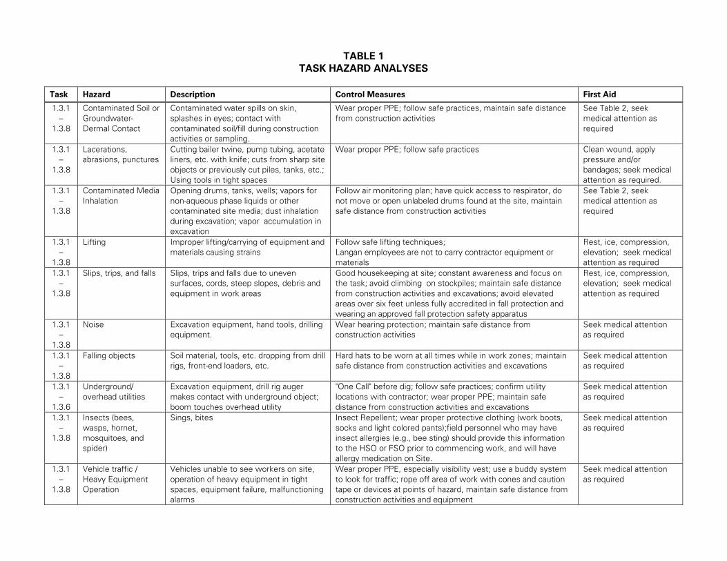
TABLE 1
TASK HAZARD ANALYSES
Task Hazard Description Control Measures First Aid
1.3.1
–
1.3.8
Contaminated Soil or
Groundwater-
Dermal Contact
Contaminated water spills on skin,
splashes in eyes; contact with
contaminated soil/fill during construction
activities or sampling.
Wear proper PPE; follow safe practices, maintain safe distance
from construction activities
See Table 2, seek
medical attention as
required
1.3.1
–
1.3.8
Lacerations,
abrasions, punctures
Cutting bailer twine, pump tubing, acetate
liners, etc. with knife; cuts from sharp site
objects or previously cut piles, tanks, etc.;
Using tools in tight spaces
Wear proper PPE; follow safe practices Clean wound, apply
pressure and/or
bandages; seek medical
attention as required.
1.3.1
–
1.3.8
Contaminated Media
Inhalation
Opening drums, tanks, wells; vapors for
non-aqueous phase liquids or other
contaminated site media; dust inhalation
during excavation; vapor accumulation in
excavation
Follow air monitoring plan; have quick access to respirator, do
not move or open unlabeled drums found at the site, maintain
safe distance from construction activities
See Table 2, seek
medical attention as
required
1.3.1
–
1.3.8
Lifting Improper lifting/carrying of equipment and
materials causing strains
Follow safe lifting techniques;
Langan employees are not to carry contractor equipment or
materials
Rest, ice, compression,
elevation; seek medical
attention as required
1.3.1
–
1.3.8
Slips, trips, and falls Slips, trips and falls due to uneven
surfaces, cords, steep slopes, debris and
equipment in work areas
Good housekeeping at site; constant awareness and focus on
the task; avoid climbing on stockpiles; maintain safe distance
from construction activities and excavations; avoid elevated
areas over six feet unless fully accredited in fall protection and
wearing an approved fall protection safety apparatus
Rest, ice, compression,
elevation; seek medical
attention as required
1.3.1
–
1.3.8
Noise Excavation equipment, hand tools, drilling
equipment.
Wear hearing protection; maintain safe distance from
construction activities
Seek medical attention
as required
1.3.1
–
1.3.8
Falling objects Soil material, tools, etc. dropping from drill
rigs, front-end loaders, etc.
Hard hats to be worn at all times while in work zones; maintain
safe distance from construction activities and excavations
Seek medical attention
as required
1.3.1
–
1.3.6
Underground/
overhead utilities
Excavation equipment, drill rig auger
makes contact with underground object;
boom touches overhead utility
"One Call" before dig; follow safe practices; confirm utility
locations with contractor; wear proper PPE; maintain safe
distance from construction activities and excavations
Seek medical attention
as required
1.3.1
–
1.3.8
Insects (bees,
wasps, hornet,
mosquitoes, and
spider)
Sings, bites Insect Repellent; wear proper protective clothing (work boots,
socks and light colored pants);field personnel who may have
insect allergies (e.g., bee sting) should provide this information
to the HSO or FSO prior to commencing work, and will have
allergy medication on Site.
Seek medical attention
as required
1.3.1
–
1.3.8
Vehicle traffic /
Heavy Equipment
Operation
Vehicles unable to see workers on site,
operation of heavy equipment in tight
spaces, equipment failure, malfunctioning
alarms
Wear proper PPE, especially visibility vest; use a buddy system
to look for traffic; rope off area of work with cones and caution
tape or devices at points of hazard, maintain safe distance from
construction activities and equipment
Seek medical attention
as required
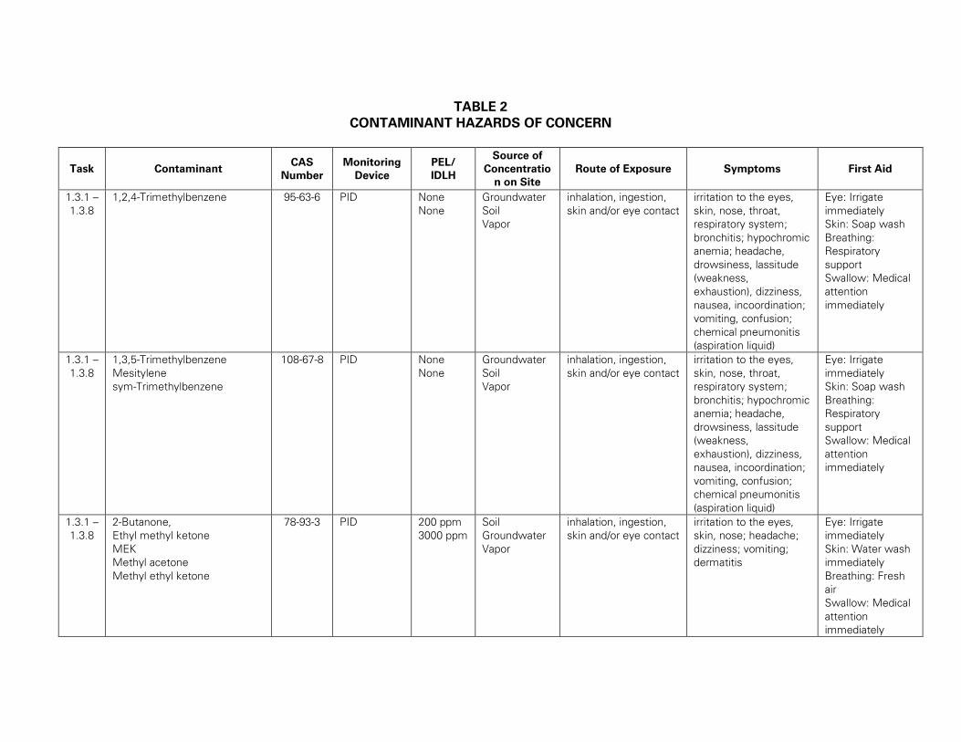
TABLE 2
CONTAMINANT HAZARDS OF CONCERN
Task Contaminant CAS
Number
Monitoring
Device
PEL/
IDLH
Source of
Concentratio
n on Site
Route of Exposure Symptoms First Aid
1.3.1 –
1.3.8
1,2,4-Trimethylbenzene 95-63-6 PID None
None
Groundwater
Soil
Vapor
inhalation, ingestion,
skin and/or eye contact
irritation to the eyes,
skin, nose, throat,
respiratory system;
bronchitis; hypochromic
anemia; headache,
drowsiness, lassitude
(weakness,
exhaustion), dizziness,
nausea, incoordination;
vomiting, confusion;
chemical pneumonitis
(aspiration liquid)
Eye: Irrigate
immediately
Skin: Soap wash
Breathing:
Respiratory
support
Swallow: Medical
attention
immediately
1.3.1 –
1.3.8
1,3,5-Trimethylbenzene
Mesitylene
sym-Trimethylbenzene
108-67-8 PID None
None
Groundwater
Soil
Vapor
inhalation, ingestion,
skin and/or eye contact
irritation to the eyes,
skin, nose, throat,
respiratory system;
bronchitis; hypochromic
anemia; headache,
drowsiness, lassitude
(weakness,
exhaustion), dizziness,
nausea, incoordination;
vomiting, confusion;
chemical pneumonitis
(aspiration liquid)
Eye: Irrigate
immediately
Skin: Soap wash
Breathing:
Respiratory
support
Swallow: Medical
attention
immediately
1.3.1 –
1.3.8
2-Butanone,
Ethyl methyl ketone
MEK
Methyl acetone
Methyl ethyl ketone
78-93-3 PID 200 ppm
3000 ppm
Soil
Groundwater
Vapor
inhalation, ingestion,
skin and/or eye contact
irritation to the eyes,
skin, nose; headache;
dizziness; vomiting;
dermatitis
Eye: Irrigate
immediately
Skin: Water wash
immediately
Breathing: Fresh
air
Swallow: Medical
attention
immediately
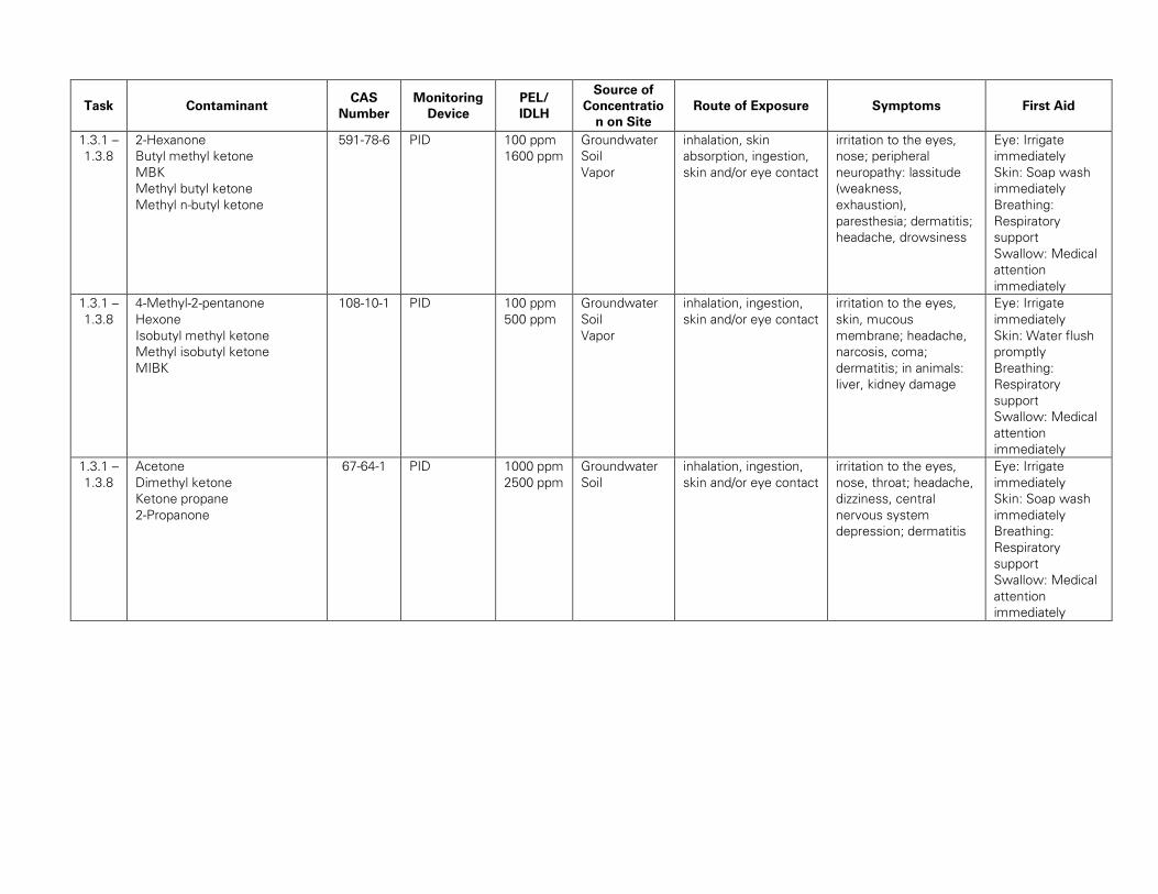
Task Contaminant CAS
Number
Monitoring
Device
PEL/
IDLH
Source of
Concentratio
n on Site
Route of Exposure Symptoms First Aid
1.3.1 –
1.3.8
2-Hexanone
Butyl methyl ketone
MBK
Methyl butyl ketone
Methyl n-butyl ketone
591-78-6 PID 100 ppm
1600 ppm
Groundwater
Soil
Vapor
inhalation, skin
absorption, ingestion,
skin and/or eye contact
irritation to the eyes,
nose; peripheral
neuropathy: lassitude
(weakness,
exhaustion),
paresthesia; dermatitis;
headache, drowsiness
Eye: Irrigate
immediately
Skin: Soap wash
immediately
Breathing:
Respiratory
support
Swallow: Medical
attention
immediately
1.3.1 –
1.3.8
4-Methyl-2-pentanone
Hexone
Isobutyl methyl ketone
Methyl isobutyl ketone
MIBK
108-10-1 PID 100 ppm
500 ppm
Groundwater
Soil
Vapor
inhalation, ingestion,
skin and/or eye contact
irritation to the eyes,
skin, mucous
membrane; headache,
narcosis, coma;
dermatitis; in animals:
liver, kidney damage
Eye: Irrigate
immediately
Skin: Water flush
promptly
Breathing:
Respiratory
support
Swallow: Medical
attention
immediately
1.3.1 –
1.3.8
Acetone
Dimethyl ketone
Ketone propane
2-Propanone
67-64-1 PID 1000 ppm
2500 ppm
Groundwater
Soil
inhalation, ingestion,
skin and/or eye contact
irritation to the eyes,
nose, throat; headache,
dizziness, central
nervous system
depression; dermatitis
Eye: Irrigate
immediately
Skin: Soap wash
immediately
Breathing:
Respiratory
support
Swallow: Medical
attention
immediately
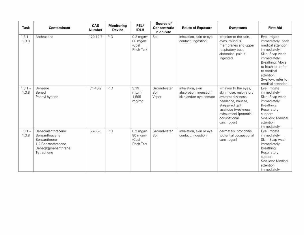
Task Contaminant CAS
Number
Monitoring
Device
PEL/
IDLH
Source of
Concentratio
n on Site
Route of Exposure Symptoms First Aid
1.3.1 –
1.3.8
Anthracene 120-12-7 PID 0.2 mg/m3
80 mg/m3
(Coal
Pitch Tar)
Soil inhalation, skin or eye
contact, ingestion
irritation to the skin,
eyes, mucous
membranes and upper
respiratory tract,
abdominal pain if
ingested.
Eye: Irrigate
immediately, seek
medical attention
immediately,
Skin: Soap wash
immediately,
Breathing: Move
to fresh air, refer
to medical
attention;
Swallow: refer to
medical attention
1.3.1 –
1.3.8
Benzene
Benzol
Phenyl hydride
71-43-2 PID 3.19
mg/m3
1,595
mg/mg3
Groundwater
Soil
Vapor
inhalation, skin
absorption, ingestion,
skin and/or eye contact
irritation to the eyes,
skin, nose, respiratory
system; dizziness;
headache, nausea,
staggered gait;
lassitude (weakness,
exhaustion) [potential
occupational
carcinogen]
Eye: Irrigate
immediately
Skin: Soap wash
immediately
Breathing:
Respiratory
support
Swallow: Medical
attention
immediately
1.3.1 –
1.3.8
Benzo(a)anthracene
Benzanthracene
Benzanthrene
1,2-Benzanthracene
Benzo[b]phenanthrene
Tetraphene
56-55-3 PID 0.2 mg/m3
80 mg/m3
(Coal
Pitch Tar)
Groundwater
Soil
inhalation, skin or eye
contact, ingestion
dermatitis, bronchitis,
[potential occupational
carcinogen]
Eye: Irrigate
immediately
Skin: Soap wash
immediately
Breathing:
Respiratory
support
Swallow: Medical
attention
immediately
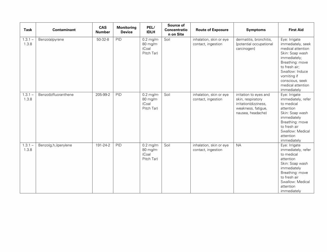
Task Contaminant CAS
Number
Monitoring
Device
PEL/
IDLH
Source of
Concentratio
n on Site
Route of Exposure Symptoms First Aid
1.3.1 –
1.3.8
Benzo(a)pyrene 50-32-8 PID 0.2 mg/m3
80 mg/m3
(Coal
Pitch Tar)
Soil inhalation, skin or eye
contact, ingestion
dermatitis, bronchitis,
[potential occupational
carcinogen]
Eye: Irrigate
immediately, seek
medical attention
Skin: Soap wash
immediately;
Breathing: move
to fresh air;
Swallow: Induce
vomiting if
conscious, seek
medical attention
immediately
1.3.1 –
1.3.8
Benzo(b)fluoranthene 205-99-2 PID 0.2 mg/m3
80 mg/m3
(Coal
Pitch Tar)
Soil inhalation, skin or eye
contact, ingestion
irritation to eyes and
skin, respiratory
irritation(dizziness,
weakness, fatigue,
nausea, headache)
Eye: Irrigate
immediately, refer
to medical
attention
Skin: Soap wash
immediately
Breathing: move
to fresh air
Swallow: Medical
attention
immediately
1.3.1 –
1.3.8
Benzo(g,h,i)perylene 191-24-2 PID 0.2 mg/m3
80 mg/m3
(Coal
Pitch Tar)
Soil inhalation, skin or eye
contact, ingestion
NA Eye: Irrigate
immediately, refer
to medical
attention
Skin: Soap wash
immediately
Breathing: move
to fresh air
Swallow: Medical
attention
immediately
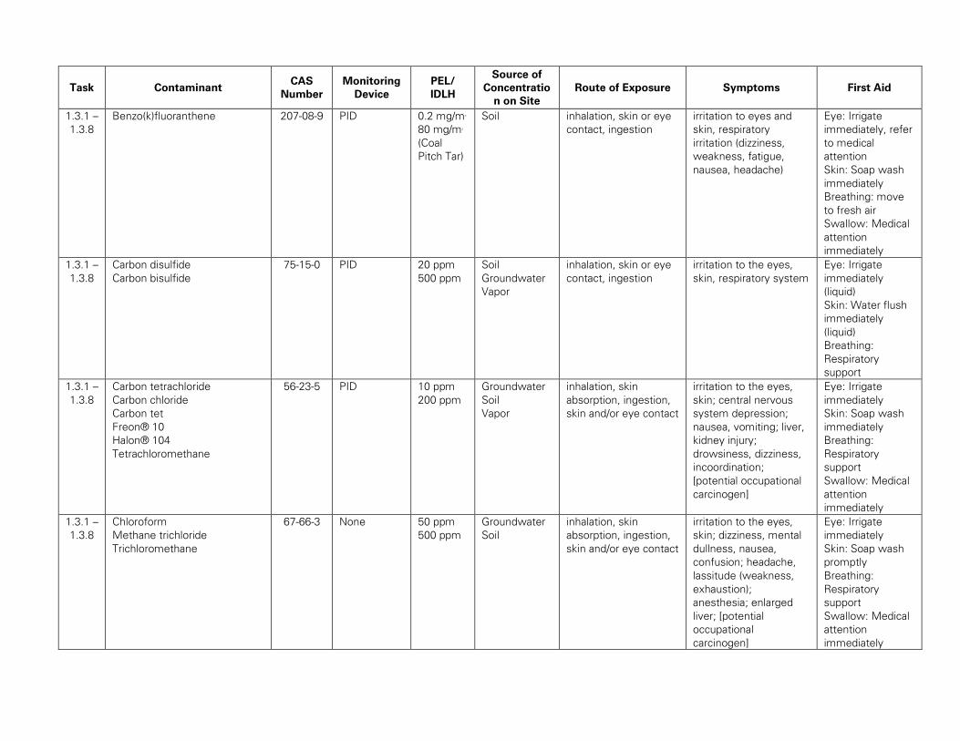
Task Contaminant CAS
Number
Monitoring
Device
PEL/
IDLH
Source of
Concentratio
n on Site
Route of Exposure Symptoms First Aid
1.3.1 –
1.3.8
Benzo(k)fluoranthene 207-08-9 PID 0.2 mg/m3
80 mg/m3
(Coal
Pitch Tar)
Soil inhalation, skin or eye
contact, ingestion
irritation to eyes and
skin, respiratory
irritation (dizziness,
weakness, fatigue,
nausea, headache)
Eye: Irrigate
immediately, refer
to medical
attention
Skin: Soap wash
immediately
Breathing: move
to fresh air
Swallow: Medical
attention
immediately
1.3.1 –
1.3.8
Carbon disulfide
Carbon bisulfide
75-15-0 PID 20 ppm
500 ppm
Soil
Groundwater
Vapor
inhalation, skin or eye
contact, ingestion
irritation to the eyes,
skin, respiratory system
Eye: Irrigate
immediately
(liquid)
Skin: Water flush
immediately
(liquid)
Breathing:
Respiratory
support
1.3.1 –
1.3.8
Carbon tetrachloride
Carbon chloride
Carbon tet
Freon® 10
Halon® 104
Tetrachloromethane
56-23-5 PID 10 ppm
200 ppm
Groundwater
Soil
Vapor
inhalation, skin
absorption, ingestion,
skin and/or eye contact
irritation to the eyes,
skin; central nervous
system depression;
nausea, vomiting; liver,
kidney injury;
drowsiness, dizziness,
incoordination;
[potential occupational
carcinogen]
Eye: Irrigate
immediately
Skin: Soap wash
immediately
Breathing:
Respiratory
support
Swallow: Medical
attention
immediately
1.3.1 –
1.3.8
Chloroform
Methane trichloride
Trichloromethane
67-66-3 None 50 ppm
500 ppm
Groundwater
Soil
inhalation, skin
absorption, ingestion,
skin and/or eye contact
irritation to the eyes,
skin; dizziness, mental
dullness, nausea,
confusion; headache,
lassitude (weakness,
exhaustion);
anesthesia; enlarged
liver; [potential
occupational
carcinogen]
Eye: Irrigate
immediately
Skin: Soap wash
promptly
Breathing:
Respiratory
support
Swallow: Medical
attention
immediately
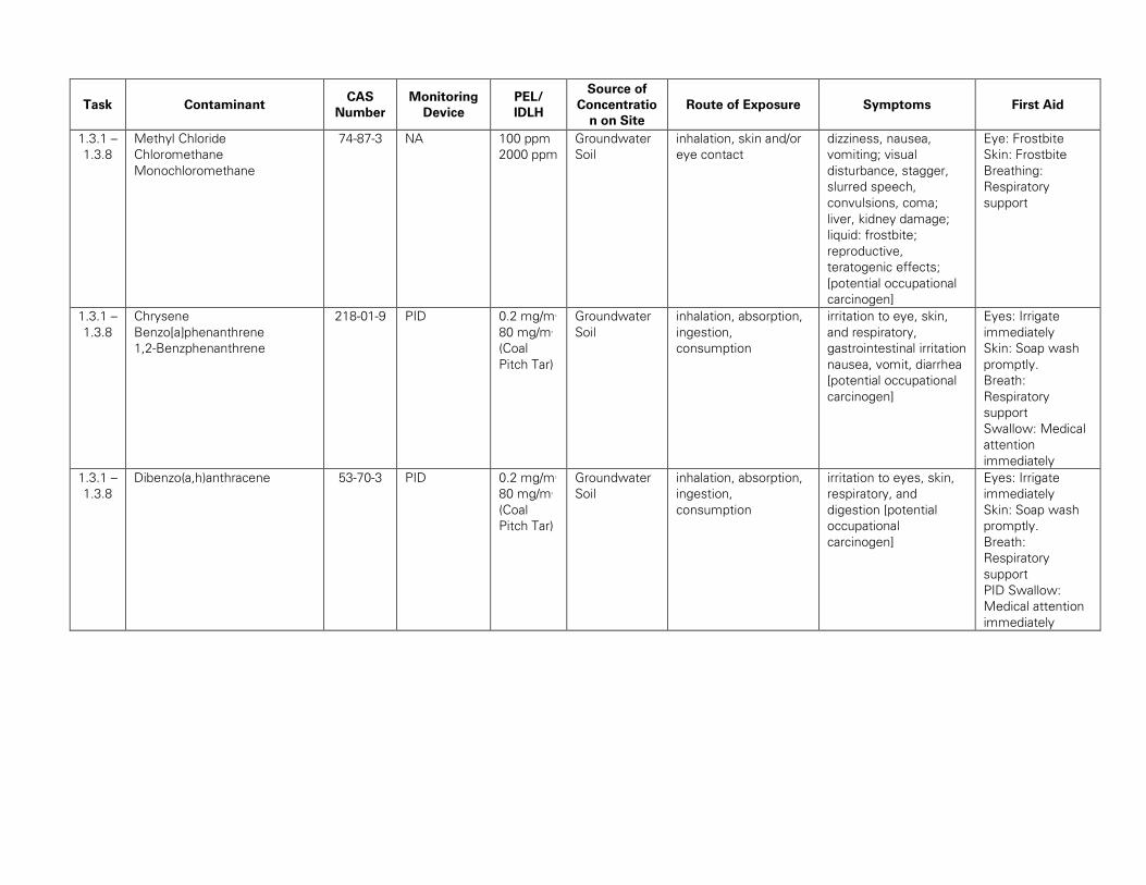
Task Contaminant CAS
Number
Monitoring
Device
PEL/
IDLH
Source of
Concentratio
n on Site
Route of Exposure Symptoms First Aid
1.3.1 –
1.3.8
Methyl Chloride
Chloromethane
Monochloromethane
74-87-3 NA 100 ppm
2000 ppm
Groundwater
Soil
inhalation, skin and/or
eye contact
dizziness, nausea,
vomiting; visual
disturbance, stagger,
slurred speech,
convulsions, coma;
liver, kidney damage;
liquid: frostbite;
reproductive,
teratogenic effects;
[potential occupational
carcinogen]
Eye: Frostbite
Skin: Frostbite
Breathing:
Respiratory
support
1.3.1 –
1.3.8
Chrysene
Benzo[a]phenanthrene
1,2-Benzphenanthrene
218-01-9 PID 0.2 mg/m3
80 mg/m3
(Coal
Pitch Tar)
Groundwater
Soil
inhalation, absorption,
ingestion,
consumption
irritation to eye, skin,
and respiratory,
gastrointestinal irritation
nausea, vomit, diarrhea
[potential occupational
carcinogen]
Eyes: Irrigate
immediately
Skin: Soap wash
promptly.
Breath:
Respiratory
support
Swallow: Medical
attention
immediately
1.3.1 –
1.3.8
Dibenzo(a,h)anthracene 53-70-3 PID 0.2 mg/m3
80 mg/m3
(Coal
Pitch Tar)
Groundwater
Soil
inhalation, absorption,
ingestion,
consumption
irritation to eyes, skin,
respiratory, and
digestion [potential
occupational
carcinogen]
Eyes: Irrigate
immediately
Skin: Soap wash
promptly.
Breath:
Respiratory
support
PID Swallow:
Medical attention
immediately
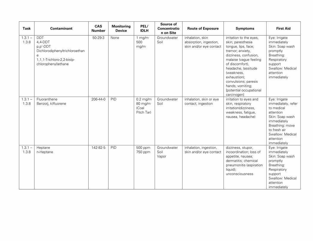
Task Contaminant CAS
Number
Monitoring
Device
PEL/
IDLH
Source of
Concentratio
n on Site
Route of Exposure Symptoms First Aid
1.3.1 –
1.3.8
DDT
4,4-DDT
p,p’-DDT
Dichlorodiphenyltrichloroethan
e
1,1,1-Trichloro-2,2-bis(p-
chlorophenyl)ethane
50-29-3 None 1 mg/m3
500
mg/m3
Groundwater
Soil
inhalation, skin
absorption, ingestion,
skin and/or eye contact
irritation to the eyes,
skin; paresthesia
tongue, lips, face;
tremor; anxiety,
dizziness, confusion,
malaise (vague feeling
of discomfort),
headache, lassitude
(weakness,
exhaustion);
convulsions; paresis
hands; vomiting;
[potential occupational
carcinogen]
Eye: Irrigate
immediately
Skin: Soap wash
promptly
Breathing:
Respiratory
support
Swallow: Medical
attention
immediately
1.3.1 –
1.3.8
Fluoranthene
Benzo(j, k)fluorene
206-44-0 PID 0.2 mg/m3
80 mg/m3
(Coal
Pitch Tar)
Groundwater
Soil
inhalation, skin or eye
contact, ingestion
irritation to eyes and
skin, respiratory
irritation(dizziness,
weakness, fatigue,
nausea, headache)
Eye: Irrigate
immediately, refer
to medical
attention
Skin: Soap wash
immediately
Breathing: move
to fresh air
Swallow: Medical
attention
immediately
1.3.1 –
1.3.8
Heptane
n-Heptane
142-82-5 PID 500 ppm
750 ppm
Groundwater
Soil
Vapor
inhalation, ingestion,
skin and/or eye contact
dizziness, stupor,
incoordination; loss of
appetite, nausea;
dermatitis; chemical
pneumonitis (aspiration
liquid);
unconsciousness
Eye: Irrigate
immediately
Skin: Soap wash
promptly
Breathing:
Respiratory
support
Swallow: Medical
attention
immediately
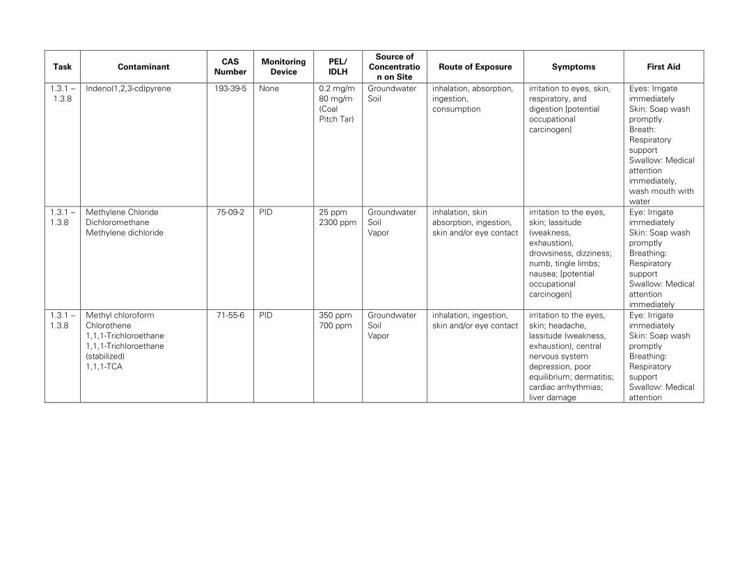
Task Contaminant CAS
Number
Monitoring
Device
PEL/
IDLH
Source of
Concentratio
n on Site
Route of Exposure Symptoms First Aid
1.3.1 –
1.3.8
Indeno(1,2,3-cd)pyrene 193-39-5 None 0.2 mg/m3
80 mg/m3
(Coal
Pitch Tar)
Groundwater
Soil
inhalation, absorption,
ingestion,
consumption
irritation to eyes, skin,
respiratory, and
digestion [potential
occupational
carcinogen]
Eyes: Irrigate
immediately
Skin: Soap wash
promptly.
Breath:
Respiratory
support
Swallow: Medical
attention
immediately,
wash mouth with
water
1.3.1 –
1.3.8
Methylene Chloride
Dichloromethane
Methylene dichloride
75-09-2 PID 25 ppm
2300 ppm
Groundwater
Soil
Vapor
inhalation, skin
absorption, ingestion,
skin and/or eye contact
irritation to the eyes,
skin; lassitude
(weakness,
exhaustion),
drowsiness, dizziness;
numb, tingle limbs;
nausea; [potential
occupational
carcinogen]
Eye: Irrigate
immediately
Skin: Soap wash
promptly
Breathing:
Respiratory
support
Swallow: Medical
attention
immediately
1.3.1 –
1.3.8
Methyl chloroform
Chlorothene
1,1,1-Trichloroethane
1,1,1-Trichloroethane
(stabilized)
1,1,1-TCA
71-55-6 PID 350 ppm
700 ppm
Groundwater
Soil
Vapor
inhalation, ingestion,
skin and/or eye contact
irritation to the eyes,
skin; headache,
lassitude (weakness,
exhaustion), central
nervous system
depression, poor
equilibrium; dermatitis;
cardiac arrhythmias;
liver damage
Eye: Irrigate
immediately
Skin: Soap wash
promptly
Breathing:
Respiratory
support
Swallow: Medical
attention
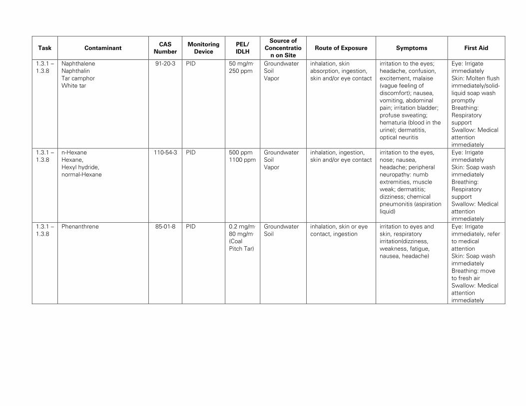
Task Contaminant CAS
Number
Monitoring
Device
PEL/
IDLH
Source of
Concentratio
n on Site
Route of Exposure Symptoms First Aid
1.3.1 –
1.3.8
Naphthalene
Naphthalin
Tar camphor
White tar
91-20-3 PID 50 mg/m3
250 ppm
Groundwater
Soil
Vapor
inhalation, skin
absorption, ingestion,
skin and/or eye contact
irritation to the eyes;
headache, confusion,
excitement, malaise
(vague feeling of
discomfort); nausea,
vomiting, abdominal
pain; irritation bladder;
profuse sweating;
hematuria (blood in the
urine); dermatitis,
optical neuritis
Eye: Irrigate
immediately
Skin: Molten flush
immediately/solid-
liquid soap wash
promptly
Breathing:
Respiratory
support
Swallow: Medical
attention
immediately
1.3.1 –
1.3.8
n-Hexane
Hexane,
Hexyl hydride,
normal-Hexane
110-54-3 PID 500 ppm
1100 ppm
Groundwater
Soil
Vapor
inhalation, ingestion,
skin and/or eye contact
irritation to the eyes,
nose; nausea,
headache; peripheral
neuropathy: numb
extremities, muscle
weak; dermatitis;
dizziness; chemical
pneumonitis (aspiration
liquid)
Eye: Irrigate
immediately
Skin: Soap wash
immediately
Breathing:
Respiratory
support
Swallow: Medical
attention
immediately
1.3.1 –
1.3.8
Phenanthrene 85-01-8 PID 0.2 mg/m3
80 mg/m3
(Coal
Pitch Tar)
Groundwater
Soil
inhalation, skin or eye
contact, ingestion
irritation to eyes and
skin, respiratory
irritation(dizziness,
weakness, fatigue,
nausea, headache)
Eye: Irrigate
immediately, refer
to medical
attention
Skin: Soap wash
immediately
Breathing: move
to fresh air
Swallow: Medical
attention
immediately
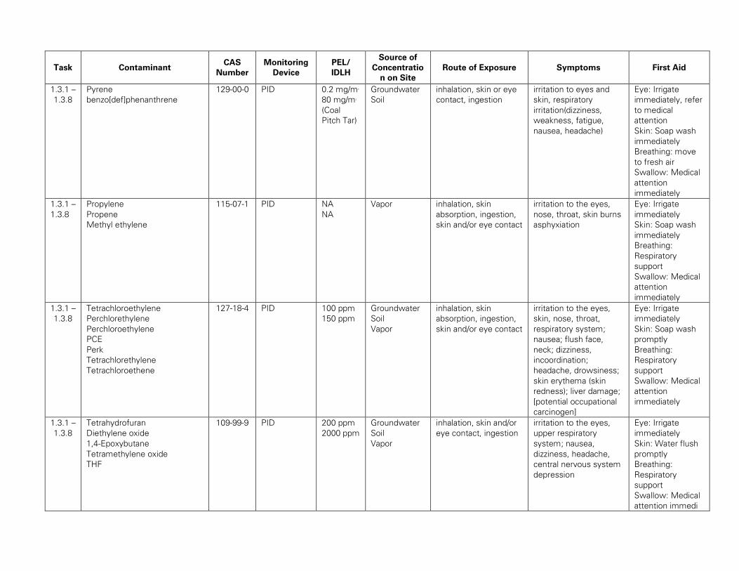
Task Contaminant CAS
Number
Monitoring
Device
PEL/
IDLH
Source of
Concentratio
n on Site
Route of Exposure Symptoms First Aid
1.3.1 –
1.3.8
Pyrene
benzo[def]phenanthrene
129-00-0 PID 0.2 mg/m3
80 mg/m3
(Coal
Pitch Tar)
Groundwater
Soil
inhalation, skin or eye
contact, ingestion
irritation to eyes and
skin, respiratory
irritation(dizziness,
weakness, fatigue,
nausea, headache)
Eye: Irrigate
immediately, refer
to medical
attention
Skin: Soap wash
immediately
Breathing: move
to fresh air
Swallow: Medical
attention
immediately
1.3.1 –
1.3.8
Propylene
Propene
Methyl ethylene
115-07-1 PID NA
NA
Vapor inhalation, skin
absorption, ingestion,
skin and/or eye contact
irritation to the eyes,
nose, throat, skin burns
asphyxiation
Eye: Irrigate
immediately
Skin: Soap wash
immediately
Breathing:
Respiratory
support
Swallow: Medical
attention
immediately
1.3.1 –
1.3.8
Tetrachloroethylene
Perchlorethylene
Perchloroethylene
PCE
Perk
Tetrachlorethylene
Tetrachloroethene
127-18-4 PID 100 ppm
150 ppm
Groundwater
Soil
Vapor
inhalation, skin
absorption, ingestion,
skin and/or eye contact
irritation to the eyes,
skin, nose, throat,
respiratory system;
nausea; flush face,
neck; dizziness,
incoordination;
headache, drowsiness;
skin erythema (skin
redness); liver damage;
[potential occupational
carcinogen]
Eye: Irrigate
immediately
Skin: Soap wash
promptly
Breathing:
Respiratory
support
Swallow: Medical
attention
immediately
1.3.1 –
1.3.8
Tetrahydrofuran
Diethylene oxide
1,4-Epoxybutane
Tetramethylene oxide
THF
109-99-9 PID 200 ppm
2000 ppm
Groundwater
Soil
Vapor
inhalation, skin and/or
eye contact, ingestion
irritation to the eyes,
upper respiratory
system; nausea,
dizziness, headache,
central nervous system
depression
Eye: Irrigate
immediately
Skin: Water flush
promptly
Breathing:
Respiratory
support
Swallow: Medical
attention immedi
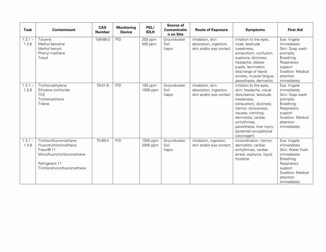
Task Contaminant CAS
Number
Monitoring
Device
PEL/
IDLH
Source of
Concentratio
n on Site
Route of Exposure Symptoms First Aid
1.3.1 –
1.3.8
Toluene
Methyl benzene
Methyl benzol
Phenyl methane
Toluol
108-88-3 PID 200 ppm
500 ppm
Groundwater
Soil
Vapor
inhalation, skin
absorption, ingestion,
skin and/or eye contact
irritation to the eyes,
nose; lassitude
(weakness,
exhaustion), confusion,
euphoria, dizziness,
headache; dilated
pupils, lacrimation
(discharge of tears);
anxiety, muscle fatigue,
paresthesia; dermatitis
Eye: Irrigate
immediately
Skin: Soap wash
promptly
Breathing:
Respiratory
support
Swallow: Medical
attention
immediately
1.3.1 –
1.3.8
Trichloroethylene
Ethylene trichloride
TCE
Trichloroethene
Trilene
79-01-6 PID 100 ppm
1000 ppm
Groundwater
Soil
Vapor
inhalation, skin
absorption, ingestion,
skin and/or eye contact
irritation to the eyes,
skin; headache, visual
disturbance, lassitude
(weakness,
exhaustion), dizziness,
tremor, drowsiness,
nausea, vomiting;
dermatitis; cardiac
arrhythmias,
paresthesia; liver injury;
[potential occupational
carcinogen]
Eye: Irrigate
immediately
Skin: Soap wash
promptly
Breathing:
Respiratory
support
Swallow: Medical
attention
immediately
1.3.1 –
1.3.8
Trichlorofluoromethane
Fluorotrichloromethane
Freon® 11
Monofluorotrichloromethane
Refrigerant 11
Trichloromonofluoromethane
75-69-4 PID 1000 ppm
2000 ppm
Groundwater
Soil
Vapor
inhalation, ingestion,
skin and/or eye contact
incoordination, tremor;
dermatitis; cardiac
arrhythmias, cardiac
arrest; asphyxia; liquid:
frostbite
Eye: Irrigate
immediately
Skin: Water flush
immediately
Breathing:
Respiratory
support
Swallow: Medical
attention
immediately
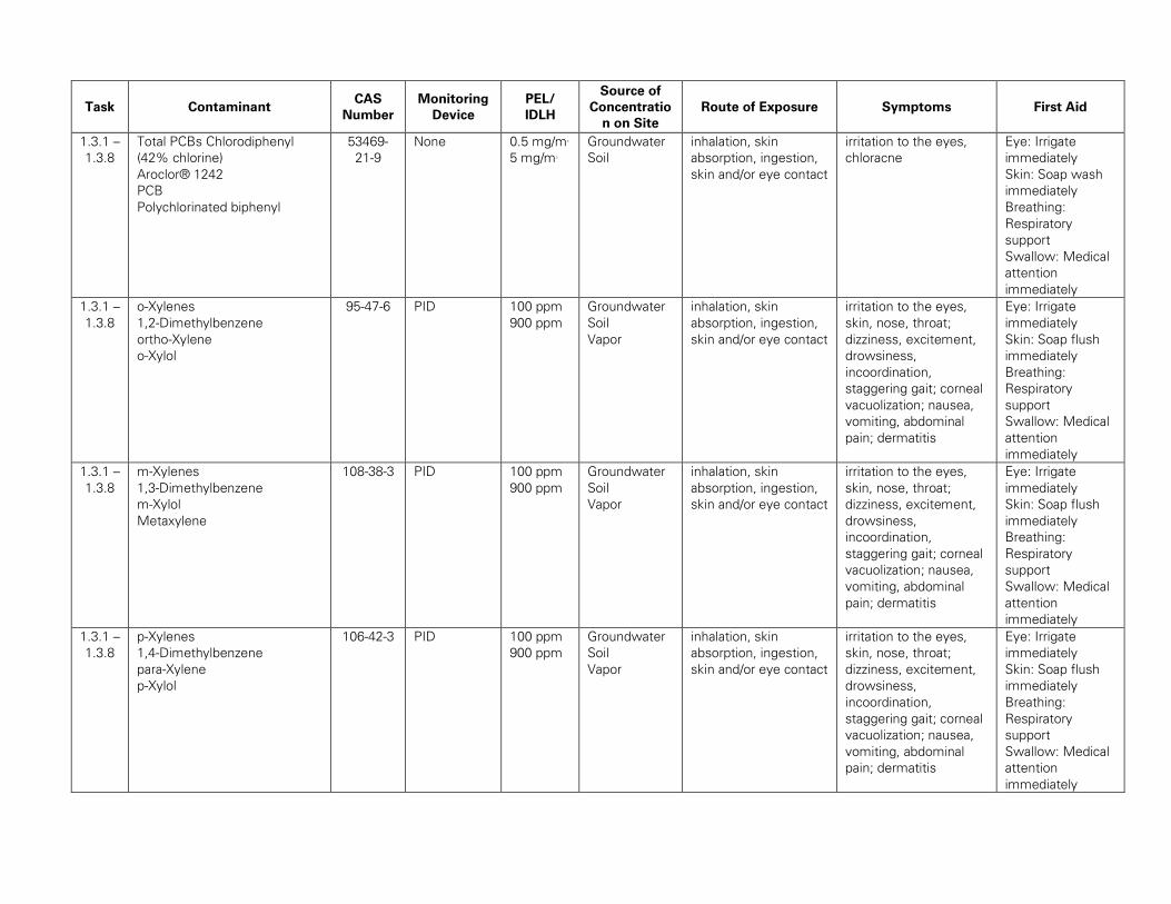
Task Contaminant CAS
Number
Monitoring
Device
PEL/
IDLH
Source of
Concentratio
n on Site
Route of Exposure Symptoms First Aid
1.3.1 –
1.3.8
Total PCBs Chlorodiphenyl
(42% chlorine)
Aroclor® 1242
PCB
Polychlorinated biphenyl
53469-
21-9
None 0.5 mg/m3
5 mg/m3
Groundwater
Soil
inhalation, skin
absorption, ingestion,
skin and/or eye contact
irritation to the eyes,
chloracne
Eye: Irrigate
immediately
Skin: Soap wash
immediately
Breathing:
Respiratory
support
Swallow: Medical
attention
immediately
1.3.1 –
1.3.8
o-Xylenes
1,2-Dimethylbenzene
ortho-Xylene
o-Xylol
95-47-6 PID 100 ppm
900 ppm
Groundwater
Soil
Vapor
inhalation, skin
absorption, ingestion,
skin and/or eye contact
irritation to the eyes,
skin, nose, throat;
dizziness, excitement,
drowsiness,
incoordination,
staggering gait; corneal
vacuolization; nausea,
vomiting, abdominal
pain; dermatitis
Eye: Irrigate
immediately
Skin: Soap flush
immediately
Breathing:
Respiratory
support
Swallow: Medical
attention
immediately
1.3.1 –
1.3.8
m-Xylenes
1,3-Dimethylbenzene
m-Xylol
Metaxylene
108-38-3 PID 100 ppm
900 ppm
Groundwater
Soil
Vapor
inhalation, skin
absorption, ingestion,
skin and/or eye contact
irritation to the eyes,
skin, nose, throat;
dizziness, excitement,
drowsiness,
incoordination,
staggering gait; corneal
vacuolization; nausea,
vomiting, abdominal
pain; dermatitis
Eye: Irrigate
immediately
Skin: Soap flush
immediately
Breathing:
Respiratory
support
Swallow: Medical
attention
immediately
1.3.1 –
1.3.8
p-Xylenes
1,4-Dimethylbenzene
para-Xylene
p-Xylol
106-42-3 PID 100 ppm
900 ppm
Groundwater
Soil
Vapor
inhalation, skin
absorption, ingestion,
skin and/or eye contact
irritation to the eyes,
skin, nose, throat;
dizziness, excitement,
drowsiness,
incoordination,
staggering gait; corneal
vacuolization; nausea,
vomiting, abdominal
pain; dermatitis
Eye: Irrigate
immediately
Skin: Soap flush
immediately
Breathing:
Respiratory
support
Swallow: Medical
attention
immediately
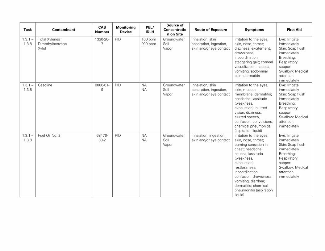
Task Contaminant CAS
Number
Monitoring
Device
PEL/
IDLH
Source of
Concentratio
n on Site
Route of Exposure Symptoms First Aid
1.3.1 –
1.3.8
Total Xylenes
Dimethylbenzene
Xylol
1330-20-
7
PID 100 ppm
900 ppm
Groundwater
Soil
Vapor
inhalation, skin
absorption, ingestion,
skin and/or eye contact
irritation to the eyes,
skin, nose, throat;
dizziness, excitement,
drowsiness,
incoordination,
staggering gait; corneal
vacuolization; nausea,
vomiting, abdominal
pain; dermatitis
Eye: Irrigate
immediately
Skin: Soap flush
immediately
Breathing:
Respiratory
support
Swallow: Medical
attention
immediately
1.3.1 –
1.3.8
Gasoline 8006-61-
9
PID NA
NA
Groundwater
Soil
Vapor
inhalation, skin
absorption, ingestion,
skin and/or eye contact
irritation to the eyes,
skin, mucous
membrane; dermatitis;
headache, lassitude
(weakness,
exhaustion), blurred
vision, dizziness,
slurred speech,
confusion, convulsions;
chemical pneumonitis
(aspiration liquid)
Eye: Irrigate
immediately
Skin: Soap flush
immediately
Breathing:
Respiratory
support
Swallow: Medical
attention
immediately
1.3.1 –
1.3.8
Fuel Oil No. 2 68476-
30-2
PID NA
NA
Groundwater
Soil
Vapor
inhalation, ingestion,
skin and/or eye contact
irritation to the eyes,
skin, nose, throat;
burning sensation in
chest; headache,
nausea, lassitude
(weakness,
exhaustion),
restlessness,
incoordination,
confusion, drowsiness;
vomiting, diarrhea;
dermatitis; chemical
pneumonitis (aspiration
liquid)
Eye: Irrigate
immediately
Skin: Soap flush
immediately
Breathing:
Respiratory
support
Swallow: Medical
attention
immediately
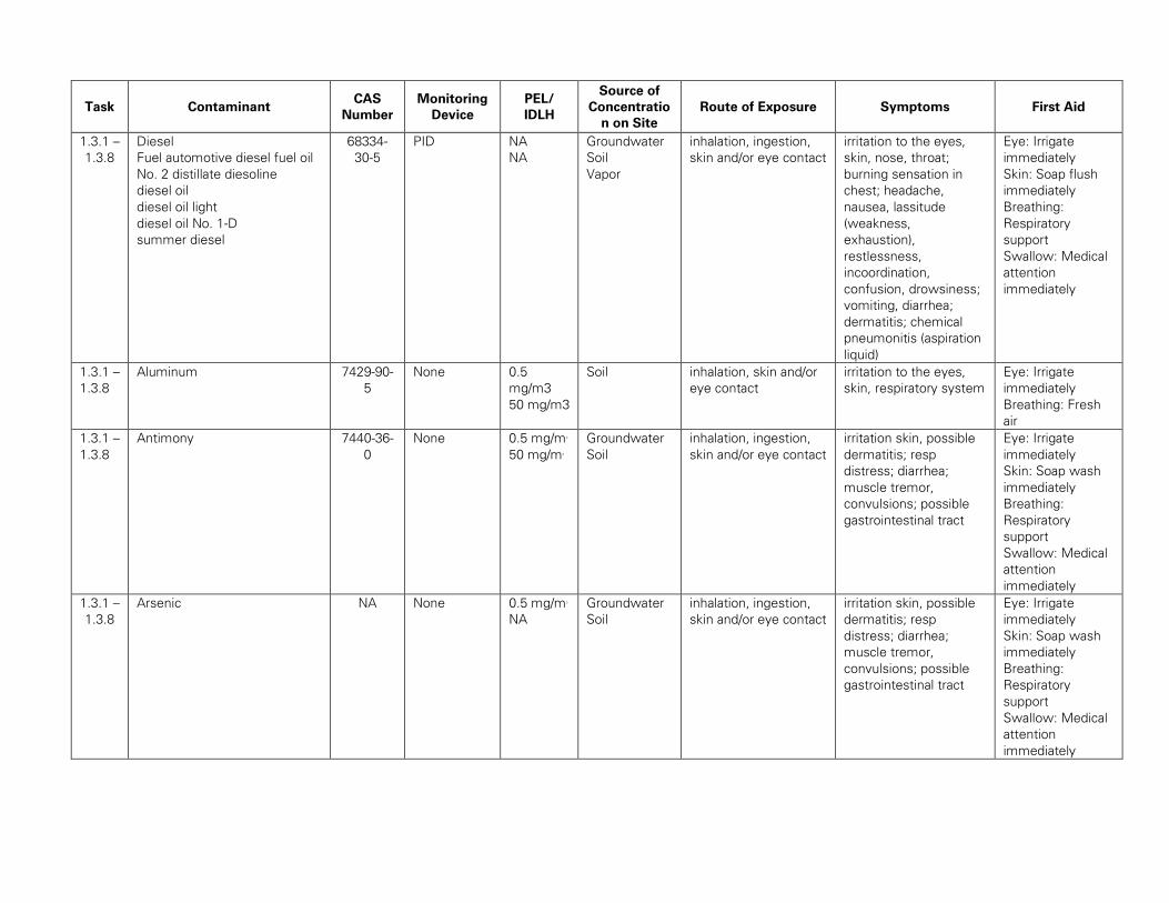
Task Contaminant CAS
Number
Monitoring
Device
PEL/
IDLH
Source of
Concentratio
n on Site
Route of Exposure Symptoms First Aid
1.3.1 –
1.3.8
Diesel
Fuel automotive diesel fuel oil
No. 2 distillate diesoline
diesel oil
diesel oil light
diesel oil No. 1-D
summer diesel
68334-
30-5
PID NA
NA
Groundwater
Soil
Vapor
inhalation, ingestion,
skin and/or eye contact
irritation to the eyes,
skin, nose, throat;
burning sensation in
chest; headache,
nausea, lassitude
(weakness,
exhaustion),
restlessness,
incoordination,
confusion, drowsiness;
vomiting, diarrhea;
dermatitis; chemical
pneumonitis (aspiration
liquid)
Eye: Irrigate
immediately
Skin: Soap flush
immediately
Breathing:
Respiratory
support
Swallow: Medical
attention
immediately
1.3.1 –
1.3.8
Aluminum 7429-90-
5
None 0.5
mg/m3
50 mg/m3
Soil inhalation, skin and/or
eye contact
irritation to the eyes,
skin, respiratory system
Eye: Irrigate
immediately
Breathing: Fresh
air
1.3.1 –
1.3.8
Antimony 7440-36-
0
None 0.5 mg/m3
50 mg/m3
Groundwater
Soil
inhalation, ingestion,
skin and/or eye contact
irritation skin, possible
dermatitis; resp
distress; diarrhea;
muscle tremor,
convulsions; possible
gastrointestinal tract
Eye: Irrigate
immediately
Skin: Soap wash
immediately
Breathing:
Respiratory
support
Swallow: Medical
attention
immediately
1.3.1 –
1.3.8
Arsenic NA None 0.5 mg/m3
NA
Groundwater
Soil
inhalation, ingestion,
skin and/or eye contact
irritation skin, possible
dermatitis; resp
distress; diarrhea;
muscle tremor,
convulsions; possible
gastrointestinal tract
Eye: Irrigate
immediately
Skin: Soap wash
immediately
Breathing:
Respiratory
support
Swallow: Medical
attention
immediately
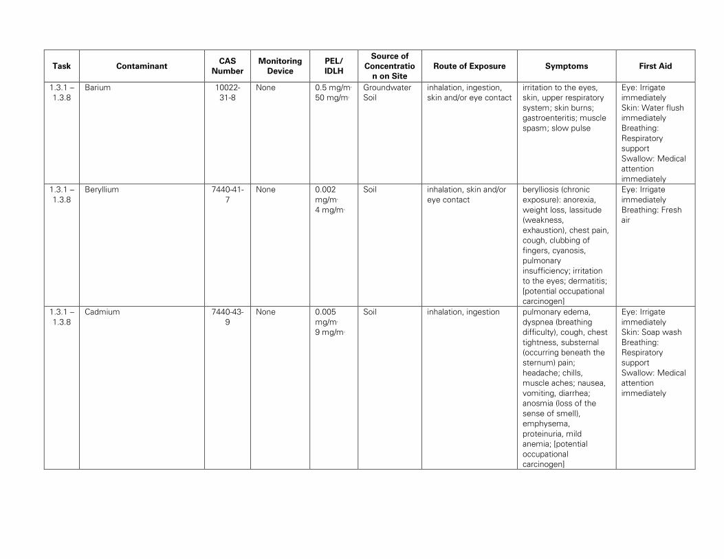
Task Contaminant CAS
Number
Monitoring
Device
PEL/
IDLH
Source of
Concentratio
n on Site
Route of Exposure Symptoms First Aid
1.3.1 –
1.3.8
Barium 10022-
31-8
None 0.5 mg/m3
50 mg/m3
Groundwater
Soil
inhalation, ingestion,
skin and/or eye contact
irritation to the eyes,
skin, upper respiratory
system; skin burns;
gastroenteritis; muscle
spasm; slow pulse
Eye: Irrigate
immediately
Skin: Water flush
immediately
Breathing:
Respiratory
support
Swallow: Medical
attention
immediately
1.3.1 –
1.3.8
Beryllium 7440-41-
7
None 0.002
mg/m3
4 mg/m3
Soil inhalation, skin and/or
eye contact
berylliosis (chronic
exposure): anorexia,
weight loss, lassitude
(weakness,
exhaustion), chest pain,
cough, clubbing of
fingers, cyanosis,
pulmonary
insufficiency; irritation
to the eyes; dermatitis;
[potential occupational
carcinogen]
Eye: Irrigate
immediately
Breathing: Fresh
air
1.3.1 –
1.3.8
Cadmium 7440-43-
9
None 0.005
mg/m3
9 mg/m3
Soil inhalation, ingestion pulmonary edema,
dyspnea (breathing
difficulty), cough, chest
tightness, substernal
(occurring beneath the
sternum) pain;
headache; chills,
muscle aches; nausea,
vomiting, diarrhea;
anosmia (loss of the
sense of smell),
emphysema,
proteinuria, mild
anemia; [potential
occupational
carcinogen]
Eye: Irrigate
immediately
Skin: Soap wash
Breathing:
Respiratory
support
Swallow: Medical
attention
immediately
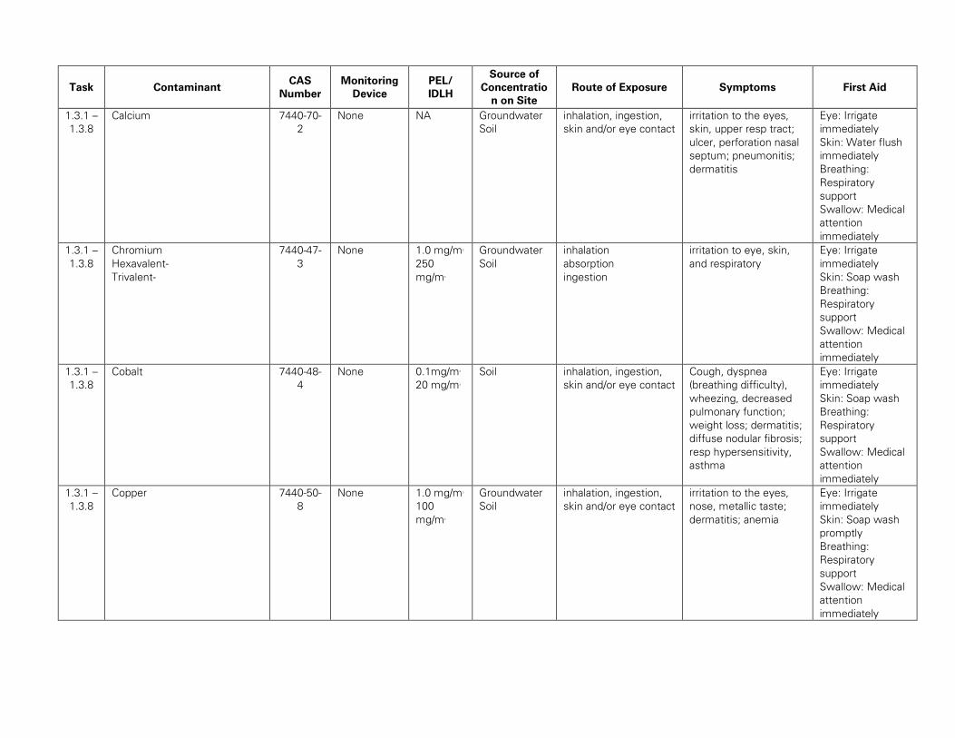
Task Contaminant CAS
Number
Monitoring
Device
PEL/
IDLH
Source of
Concentratio
n on Site
Route of Exposure Symptoms First Aid
1.3.1 –
1.3.8
Calcium 7440-70-
2
None NA Groundwater
Soil
inhalation, ingestion,
skin and/or eye contact
irritation to the eyes,
skin, upper resp tract;
ulcer, perforation nasal
septum; pneumonitis;
dermatitis
Eye: Irrigate
immediately
Skin: Water flush
immediately
Breathing:
Respiratory
support
Swallow: Medical
attention
immediately
1.3.1 –
1.3.8
Chromium
Hexavalent-
Trivalent-
7440-47-
3
None 1.0 mg/m3
250
mg/m3
Groundwater
Soil
inhalation
absorption
ingestion
irritation to eye, skin,
and respiratory
Eye: Irrigate
immediately
Skin: Soap wash
Breathing:
Respiratory
support
Swallow: Medical
attention
immediately
1.3.1 –
1.3.8
Cobalt 7440-48-
4
None 0.1mg/m3
20 mg/m3
Soil inhalation, ingestion,
skin and/or eye contact
Cough, dyspnea
(breathing difficulty),
wheezing, decreased
pulmonary function;
weight loss; dermatitis;
diffuse nodular fibrosis;
resp hypersensitivity,
asthma
Eye: Irrigate
immediately
Skin: Soap wash
Breathing:
Respiratory
support
Swallow: Medical
attention
immediately
1.3.1 –
1.3.8
Copper 7440-50-
8
None 1.0 mg/m3
100
mg/m3
Groundwater
Soil
inhalation, ingestion,
skin and/or eye contact
irritation to the eyes,
nose, metallic taste;
dermatitis; anemia
Eye: Irrigate
immediately
Skin: Soap wash
promptly
Breathing:
Respiratory
support
Swallow: Medical
attention
immediately
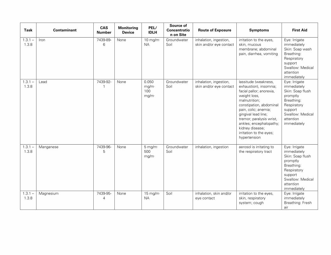
Task Contaminant CAS
Number
Monitoring
Device
PEL/
IDLH
Source of
Concentratio
n on Site
Route of Exposure Symptoms First Aid
1.3.1 –
1.3.8
Iron 7439-89-
6
None 10 mg/m3
NA
Groundwater
Soil
inhalation, ingestion,
skin and/or eye contact
irritation to the eyes,
skin, mucous
membrane; abdominal
pain, diarrhea, vomiting
Eye: Irrigate
immediately
Skin: Soap wash
Breathing:
Respiratory
support
Swallow: Medical
attention
immediately
1.3.1 –
1.3.8
Lead 7439-92-
1
None 0.050
mg/m3
100
mg/m3
Groundwater
Soil
inhalation, ingestion,
skin and/or eye contact
lassitude (weakness,
exhaustion), insomnia;
facial pallor; anorexia,
weight loss,
malnutrition;
constipation, abdominal
pain, colic; anemia;
gingival lead line;
tremor; paralysis wrist,
ankles; encephalopathy;
kidney disease;
irritation to the eyes;
hypertension
Eye: Irrigate
immediately
Skin: Soap flush
promptly
Breathing:
Respiratory
support
Swallow: Medical
attention
immediately
1.3.1 –
1.3.8
Manganese 7439-96-
5
None 5 mg/m3
500
mg/m3
Groundwater
Soil
inhalation, ingestion aerosol is irritating to
the respiratory tract
Eye: Irrigate
immediately
Skin: Soap flush
promptly
Breathing:
Respiratory
support
Swallow: Medical
attention
immediately
1.3.1 –
1.3.8
Magnesium 7439-95-
4
None 15 mg/m3
NA
Soil inhalation, skin and/or
eye contact
irritation to the eyes,
skin, respiratory
system; cough
Eye: Irrigate
immediately
Breathing: Fresh
air
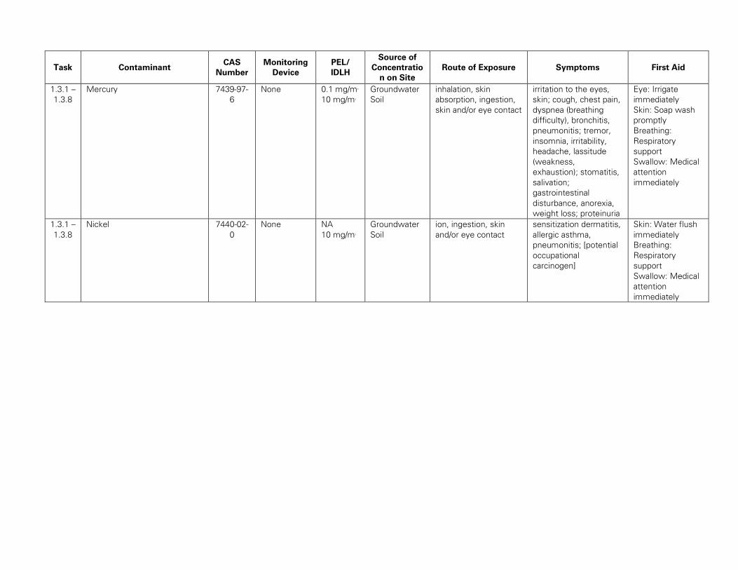
Task Contaminant CAS
Number
Monitoring
Device
PEL/
IDLH
Source of
Concentratio
n on Site
Route of Exposure Symptoms First Aid
1.3.1 –
1.3.8
Mercury 7439-97-
6
None 0.1 mg/m3
10 mg/m3
Groundwater
Soil
inhalation, skin
absorption, ingestion,
skin and/or eye contact
irritation to the eyes,
skin; cough, chest pain,
dyspnea (breathing
difficulty), bronchitis,
pneumonitis; tremor,
insomnia, irritability,
headache, lassitude
(weakness,
exhaustion); stomatitis,
salivation;
gastrointestinal
disturbance, anorexia,
weight loss; proteinuria
Eye: Irrigate
immediately
Skin: Soap wash
promptly
Breathing:
Respiratory
support
Swallow: Medical
attention
immediately
1.3.1 –
1.3.8
Nickel 7440-02-
0
None NA
10 mg/m3
Groundwater
Soil
ion, ingestion, skin
and/or eye contact
sensitization dermatitis,
allergic asthma,
pneumonitis; [potential
occupational
carcinogen]
Skin: Water flush
immediately
Breathing:
Respiratory
support
Swallow: Medical
attention
immediately
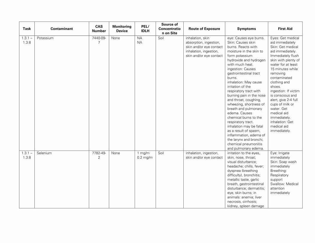
Task Contaminant CAS
Number
Monitoring
Device
PEL/
IDLH
Source of
Concentratio
n on Site
Route of Exposure Symptoms First Aid
1.3.1 –
1.3.8
Potassium 7440-09-
7
None NA
NA
Soil inhalation, skin
absorption, ingestion,
skin and/or eye contact
inhalation, ingestion,
skin and/or eye contact
eye: Causes eye burns.
Skin: Causes skin
burns. Reacts with
moisture in the skin to
form potassium
hydroxide and hydrogen
with much heat.
ingestion: Causes
gastrointestinal tract
burns.
inhalation: May cause
irritation of the
respiratory tract with
burning pain in the nose
and throat, coughing,
wheezing, shortness of
breath and pulmonary
edema. Causes
chemical burns to the
respiratory tract.
inhalation may be fatal
as a result of spasm,
inflammation, edema of
the larynx and bronchi,
chemical pneumonitis
and pulmonary edema.
Eyes: Get medical
aid immediately
Skin: Get medical
aid immediately.
Immediately flush
skin with plenty of
water for at least
15 minutes while
removing
contaminated
clothing and
shoes.
ingestion: If victim
is conscious and
alert, give 2-4 full
cups of milk or
water. Get
medical aid
immediately.
inhalation: Get
medical aid
immediately.
1.3.1 –
1.3.8
Selenium 7782-49-
2
None 1 mg/m3
0.2 mg/m3
Soil inhalation, ingestion,
skin and/or eye contact
irritation to the eyes,
skin, nose, throat;
visual disturbance;
headache; chills, fever;
dyspnea (breathing
difficulty), bronchitis;
metallic taste, garlic
breath, gastrointestinal
disturbance; dermatitis;
eye, skin burns; in
animals: anemia; liver
necrosis, cirrhosis;
kidney, spleen damage
Eye: Irrigate
immediately
Skin: Soap wash
immediately
Breathing:
Respiratory
support
Swallow: Medical
attention
immediately
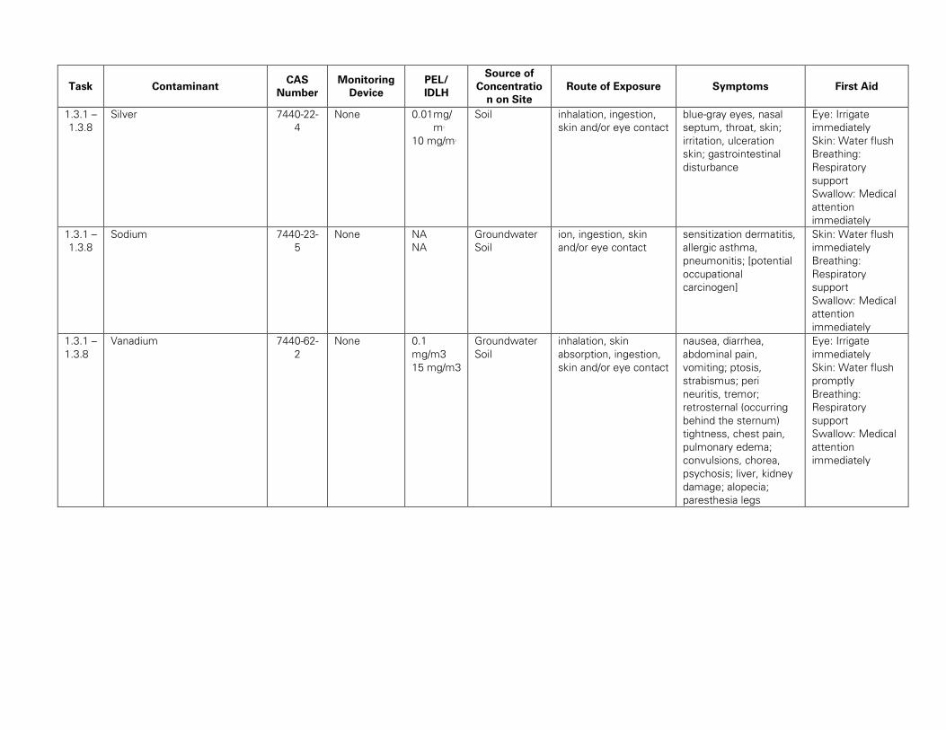
Task Contaminant CAS
Number
Monitoring
Device
PEL/
IDLH
Source of
Concentratio
n on Site
Route of Exposure Symptoms First Aid
1.3.1 –
1.3.8
Silver 7440-22-
4
None 0.01 mg/
m3
10 mg/m3
Soil inhalation, ingestion,
skin and/or eye contact
blue-gray eyes, nasal
septum, throat, skin;
irritation, ulceration
skin; gastrointestinal
disturbance
Eye: Irrigate
immediately
Skin: Water flush
Breathing:
Respiratory
support
Swallow: Medical
attention
immediately
1.3.1 –
1.3.8
Sodium 7440-23-
5
None NA
NA
Groundwater
Soil
ion, ingestion, skin
and/or eye contact
sensitization dermatitis,
allergic asthma,
pneumonitis; [potential
occupational
carcinogen]
Skin: Water flush
immediately
Breathing:
Respiratory
support
Swallow: Medical
attention
immediately
1.3.1 –
1.3.8
Vanadium 7440-62-
2
None 0.1
mg/m3
15 mg/m3
Groundwater
Soil
inhalation, skin
absorption, ingestion,
skin and/or eye contact
nausea, diarrhea,
abdominal pain,
vomiting; ptosis,
strabismus; peri
neuritis, tremor;
retrosternal (occurring
behind the sternum)
tightness, chest pain,
pulmonary edema;
convulsions, chorea,
psychosis; liver, kidney
damage; alopecia;
paresthesia legs
Eye: Irrigate
immediately
Skin: Water flush
promptly
Breathing:
Respiratory
support
Swallow: Medical
attention
immediately
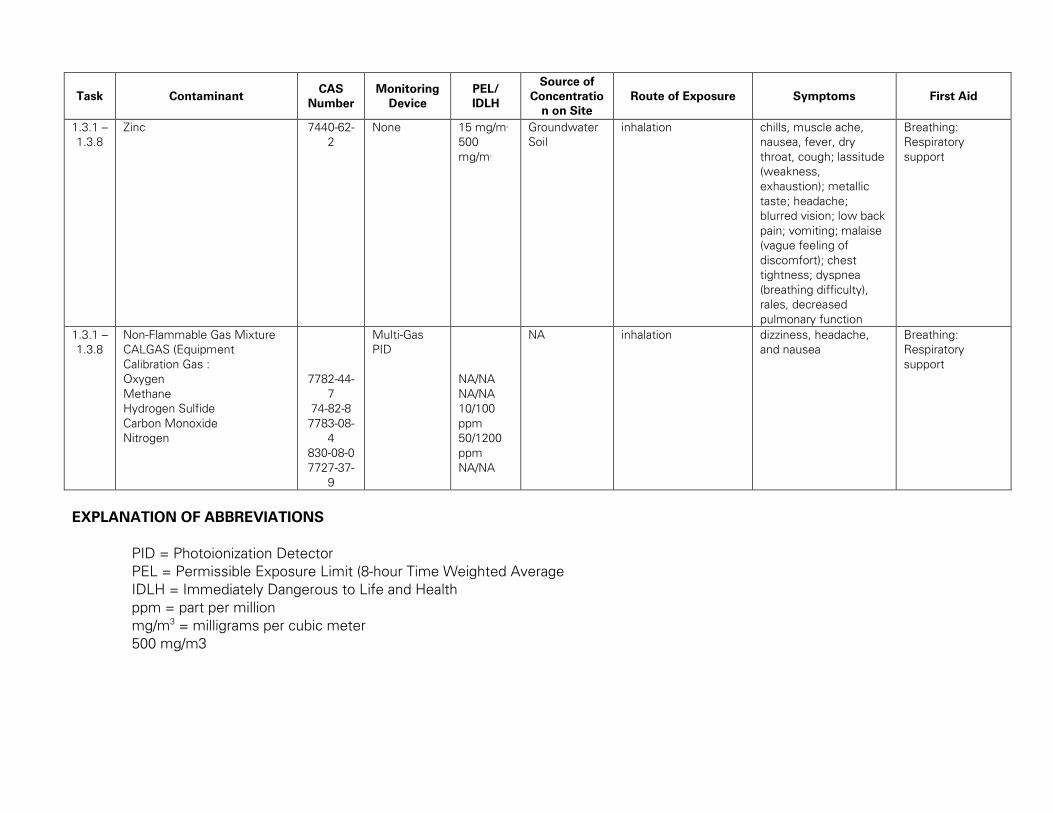
Task Contaminant CAS
Number
Monitoring
Device
PEL/
IDLH
Source of
Concentratio
n on Site
Route of Exposure Symptoms First Aid
1.3.1 –
1.3.8
Zinc 7440-62-
2
None 15 mg/m3
500
mg/m3
Groundwater
Soil
inhalation chills, muscle ache,
nausea, fever, dry
throat, cough; lassitude
(weakness,
exhaustion); metallic
taste; headache;
blurred vision; low back
pain; vomiting; malaise
(vague feeling of
discomfort); chest
tightness; dyspnea
(breathing difficulty),
rales, decreased
pulmonary function
Breathing:
Respiratory
support
1.3.1 –
1.3.8
Non-Flammable Gas Mixture
CALGAS (Equipment
Calibration Gas :
Oxygen
Methane
Hydrogen Sulfide
Carbon Monoxide
Nitrogen
7782-44-
7
74-82-8
7783-08-
4
830-08-0
7727-37-
9
Multi-Gas
PID
NA/NA
NA/NA
10/100
ppm
50/1200
ppm
NA/NA
NA inhalation dizziness, headache,
and nausea
Breathing:
Respiratory
support
EXPLANATION OF ABBREVIATIONS
PID = Photoionization Detector
PEL = Permissible Exposure Limit (8-hour Time Weighted Average
IDLH = Immediately Dangerous to Life and Health
ppm = part per million
mg/m3 = milligrams per cubic meter
500 mg/m3
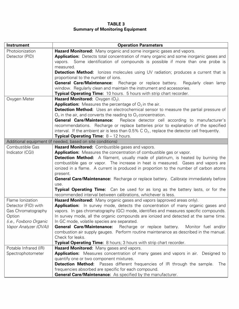
TABLE 3
Summary of Monitoring Equipment
Instrument Operation Parameters
Photoionization
Detector (PID)
Hazard Monitored: Many organic and some inorganic gases and vapors.
Application: Detects total concentration of many organic and some inorganic gases and
vapors. Some identification of compounds is possible if more than one probe is
measured.
Detection Method: Ionizes molecules using UV radiation; produces a current that is
proportional to the number of ions.
General Care/Maintenance: Recharge or replace battery. Regularly clean lamp
window. Regularly clean and maintain the instrument and accessories.
Typical Operating Time: 10 hours. 5 hours with strip chart recorder.
Oxygen Meter Hazard Monitored: Oxygen (O2).
Application: Measures the percentage of O2 in the air.
Detection Method: Uses an electrochemical sensor to measure the partial pressure of
O2 in the air, and converts the reading to O2 concentration.
General Care/Maintenance: Replace detector cell according to manufacturer’s
recommendations. Recharge or replace batteries prior to explanation of the specified
interval. If the ambient air is less than 0.5% C O2 , replace the detector cell frequently.
Typical Operating Time: 8 – 12 hours.
Additional equipment (if needed, based on site conditions)
Combustible Gas
Indicator (CGI)
Hazard Monitored: Combustible gases and vapors.
Application: Measures the concentration of combustible gas or vapor.
Detection Method: A filament, usually made of platinum, is heated by burning the
combustible gas or vapor. The increase in heat is measured. Gases and vapors are
ionized in a flame. A current is produced in proportion to the number of carbon atoms
present.
General Care/Maintenance: Recharge or replace battery. Calibrate immediately before
use.
Typical Operating Time: Can be used for as long as the battery lasts, or for the
recommended interval between calibrations, whichever is less.
Flame Ionization
Detector (FID) with
Gas Chromatography
Option
(i.e., Foxboro Organic
Vapor Analyzer (OVA))
Hazard Monitored: Many organic gases and vapors (approved areas only).
Application: In survey mode, detects the concentration of many organic gases and
vapors. In gas chromatography (GC) mode, identifies and measures specific compounds.
In survey mode, all the organic compounds are ionized and detected at the same time.
In GC mode, volatile species are separated.
General Care/Maintenance: Recharge or replace battery. Monitor fuel and/or
combustion air supply gauges. Perform routine maintenance as described in the manual.
Check for leaks.
Typical Operating Time: 8 hours; 3 hours with strip chart recorder.
Potable Infrared (IR)
Spectrophotometer
Hazard Monitored: Many gases and vapors.
Application: Measures concentration of many gases and vapors in air. Designed to
quantify one or two component mixtures.
Detection Method: Passes different frequencies of IR through the sample. The
frequencies absorbed are specific for each compound.
General Care/Maintenance: As specified by the manufacturer.
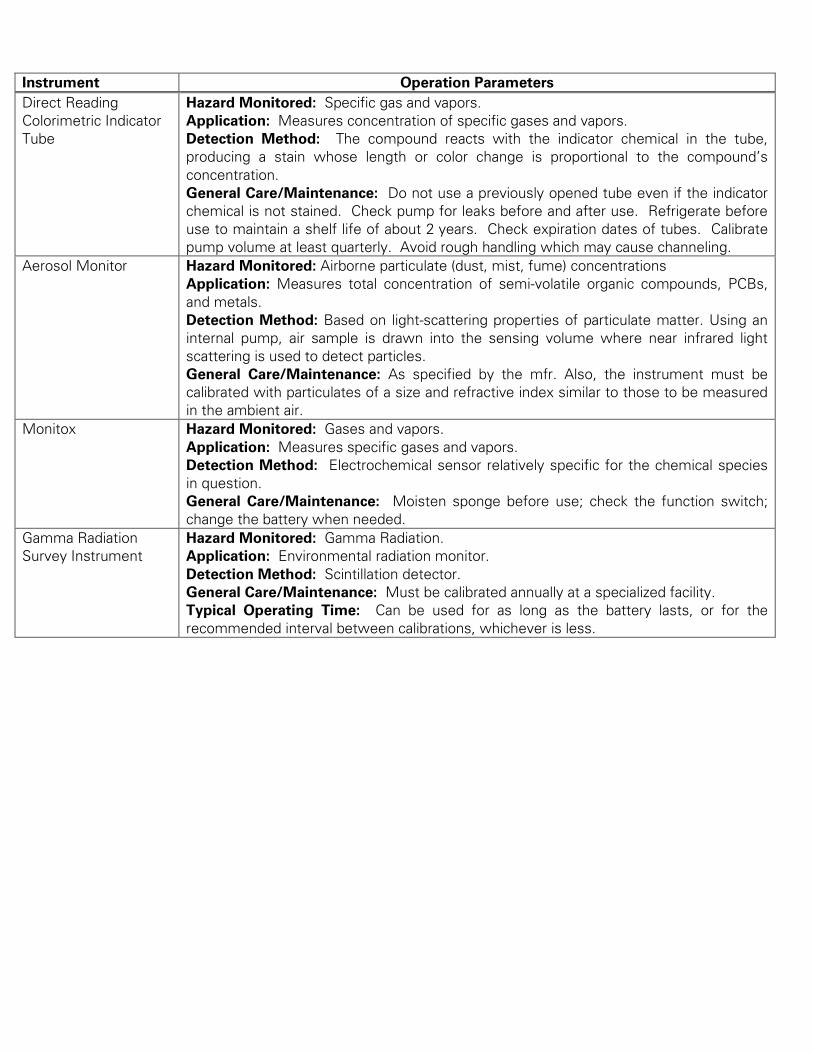
Instrument Operation Parameters
Direct Reading
Colorimetric Indicator
Tube
Hazard Monitored: Specific gas and vapors.
Application: Measures concentration of specific gases and vapors.
Detection Method: The compound reacts with the indicator chemical in the tube,
producing a stain whose length or color change is proportional to the compound’s
concentration.
General Care/Maintenance: Do not use a previously opened tube even if the indicator
chemical is not stained. Check pump for leaks before and after use. Refrigerate before
use to maintain a shelf life of about 2 years. Check expiration dates of tubes. Calibrate
pump volume at least quarterly. Avoid rough handling which may cause channeling.
Aerosol Monitor Hazard Monitored: Airborne particulate (dust, mist, fume) concentrations
Application: Measures total concentration of semi-volatile organic compounds, PCBs,
and metals.
Detection Method: Based on light-scattering properties of particulate matter. Using an
internal pump, air sample is drawn into the sensing volume where near infrared light
scattering is used to detect particles.
General Care/Maintenance: As specified by the mfr. Also, the instrument must be
calibrated with particulates of a size and refractive index similar to those to be measured
in the ambient air.
Monitox Hazard Monitored: Gases and vapors.
Application: Measures specific gases and vapors.
Detection Method: Electrochemical sensor relatively specific for the chemical species
in question.
General Care/Maintenance: Moisten sponge before use; check the function switch;
change the battery when needed.
Gamma Radiation
Survey Instrument
Hazard Monitored: Gamma Radiation.
Application: Environmental radiation monitor.
Detection Method: Scintillation detector.
General Care/Maintenance: Must be calibrated annually at a specialized facility.
Typical Operating Time: Can be used for as long as the battery lasts, or for the
recommended interval between calibrations, whichever is less.
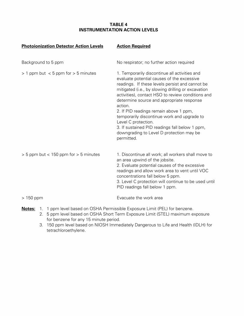
TABLE 4
INSTRUMENTATION ACTION LEVELS
Photoionization Detector Action Levels Action Required
Background to 5 ppm No respirator; no further action required
> 1 ppm but < 5 ppm for > 5 minutes 1. Temporarily discontinue all activities and
evaluate potential causes of the excessive
readings. If these levels persist and cannot be
mitigated (i.e., by slowing drilling or excavation
activities), contact HSO to review conditions and
determine source and appropriate response
action.
2. If PID readings remain above 1 ppm,
temporarily discontinue work and upgrade to
Level C protection.
3. If sustained PID readings fall below 1 ppm,
downgrading to Level D protection may be
permitted.
> 5 ppm but < 150 ppm for > 5 minutes 1. Discontinue all work; all workers shall move to
an area upwind of the jobsite.
2. Evaluate potential causes of the excessive
readings and allow work area to vent until VOC
concentrations fall below 5 ppm.
3. Level C protection will continue to be used until
PID readings fall below 1 ppm.
> 150 ppm Evacuate the work area
Notes: 1. 1 ppm level based on OSHA Permissible Exposure Limit (PEL) for benzene.
2. 5 ppm level based on OSHA Short Term Exposure Limit (STEL) maximum exposure
for benzene for any 15 minute period.
3. 150 ppm level based on NIOSH Immediately Dangerous to Life and Health (IDLH) for
tetrachloroethylene.
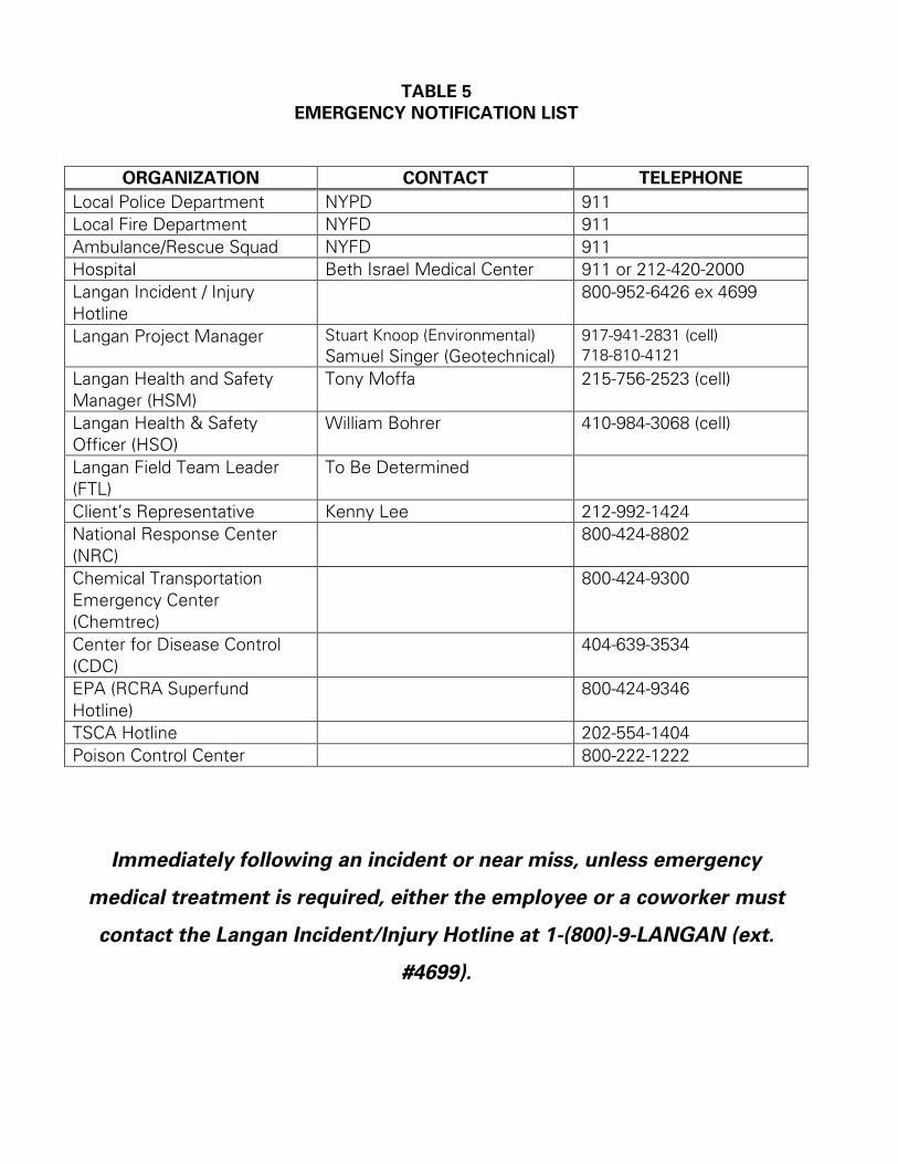
TABLE 5
EMERGENCY NOTIFICATION LIST
ORGANIZATION CONTACT TELEPHONE
Local Police Department NYPD 911
Local Fire Department NYFD 911
Ambulance/Rescue Squad NYFD 911
Hospital Beth Israel Medical Center 911 or 212-420-2000
Langan Incident / Injury
Hotline
800-952-6426 ex 4699
Langan Project Manager Stuart Knoop (Environmental)
Samuel Singer (Geotechnical)
917-941-2831 (cell)
718-810-4121
Langan Health and Safety
Manager (HSM)
Tony Moffa 215-756-2523 (cell)
Langan Health & Safety
Officer (HSO)
William Bohrer 410-984-3068 (cell)
Langan Field Team Leader
(FTL)
To Be Determined
Client’s Representative Kenny Lee 212-992-1424
National Response Center
(NRC)
800-424-8802
Chemical Transportation
Emergency Center
(Chemtrec)
800-424-9300
Center for Disease Control
(CDC)
404-639-3534
EPA (RCRA Superfund
Hotline)
800-424-9346
TSCA Hotline 202-554-1404
Poison Control Center 800-222-1222
Immediately following an incident or near miss, unless emergency
medical treatment is required, either the employee or a coworker must
contact the Langan Incident/Injury Hotline at 1-(800)-9-LANGAN (ext.
#4699).
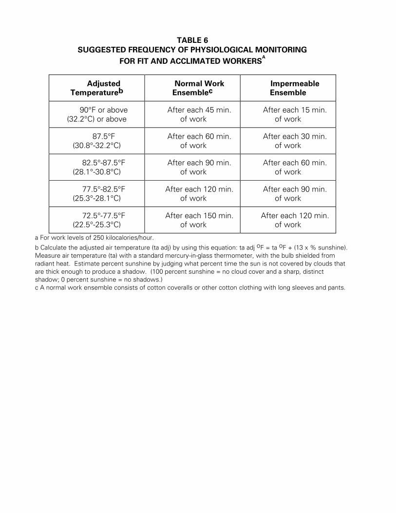
TABLE 6
SUGGESTED FREQUENCY OF PHYSIOLOGICAL MONITORING
FOR FIT AND ACCLIMATED WORKERSA
Adjusted
Temperatureb
Normal Work
Ensemblec
Impermeable
Ensemble
90°F or above
(32.2°C) or above
After each 45 min.
of work
After each 15 min.
of work
87.5°F
(30.8°-32.2°C)
After each 60 min.
of work
After each 30 min.
of work
82.5°-87.5°F
(28.1°-30.8°C)
After each 90 min.
of work
After each 60 min.
of work
77.5°-82.5°F
(25.3°-28.1°C)
After each 120 min.
of work
After each 90 min.
of work
72.5°-77.5°F
(22.5°-25.3°C)
After each 150 min.
of work
After each 120 min.
of work
a For work levels of 250 kilocalories/hour.
b Calculate the adjusted air temperature (ta adj) by using this equation: ta adj oF = ta oF + (13 x % sunshine).
Measure air temperature (ta) with a standard mercury-in-glass thermometer, with the bulb shielded from
radiant heat. Estimate percent sunshine by judging what percent time the sun is not covered by clouds that
are thick enough to produce a shadow. (100 percent sunshine = no cloud cover and a sharp, distinct
shadow; 0 percent sunshine = no shadows.)
c A normal work ensemble consists of cotton coveralls or other cotton clothing with long sleeves and pants.
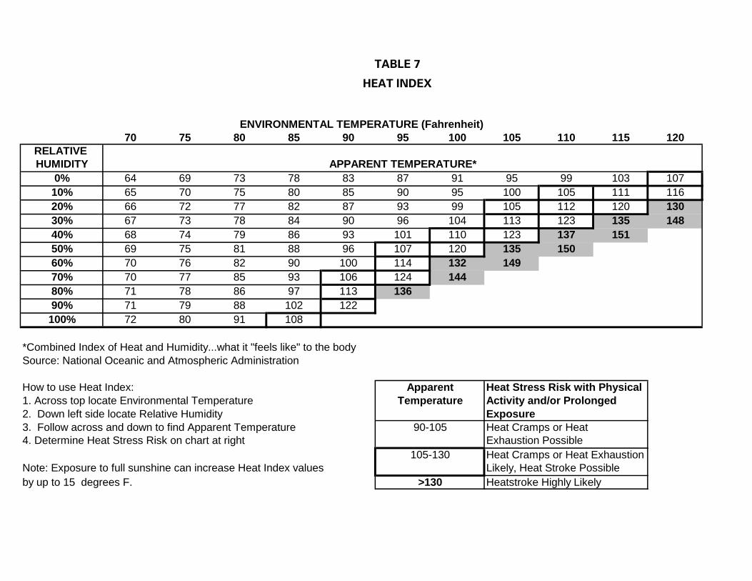
TABLE 7
HEAT INDEX
ENVIRONMENTAL TEMPERATURE (Fahrenheit)
70 75 80 85 90 95 100 105 110 115 120
RELATIVE
HUMIDITY APPARENT TEMPERATURE*
0% 64 69 73 78 83 87 91 95 99 103 107
10% 65 70 75 80 85 90 95 100 105 111 116
20% 66 72 77 82 87 93 99 105 112 120 130
30% 67 73 78 84 90 96 104 113 123 135 148
40% 68 74 79 86 93 101 110 123 137 151
50% 69 75 81 88 96 107 120 135 150
60% 70 76 82 90 100 114 132 149
70% 70 77 85 93 106 124 144
80% 71 78 86 97 113 136
90% 71 79 88 102 122
100% 72 80 91 108
*Combined Index of Heat and Humidity...what it "feels like" to the body
Source: National Oceanic and Atmospheric Administration
How to use Heat Index: Apparent Heat Stress Risk with Physical
1. Across top locate Environmental Temperature Temperature Activity and/or Prolonged
2. Down left side locate Relative Humidity Exposure
3. Follow across and down to find Apparent Temperature 90-105 Heat Cramps or Heat
4. Determine Heat Stress Risk on chart at right Exhaustion Possible
105-130 Heat Cramps or Heat Exhaustion
Note: Exposure to full sunshine can increase Heat Index values Likely, Heat Stroke Possible
by up to 15 degrees F. >130 Heatstroke Highly Likely

FIGURES
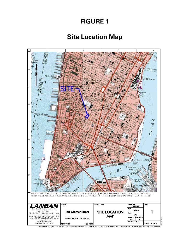
FIGURE 1
Site Location Map
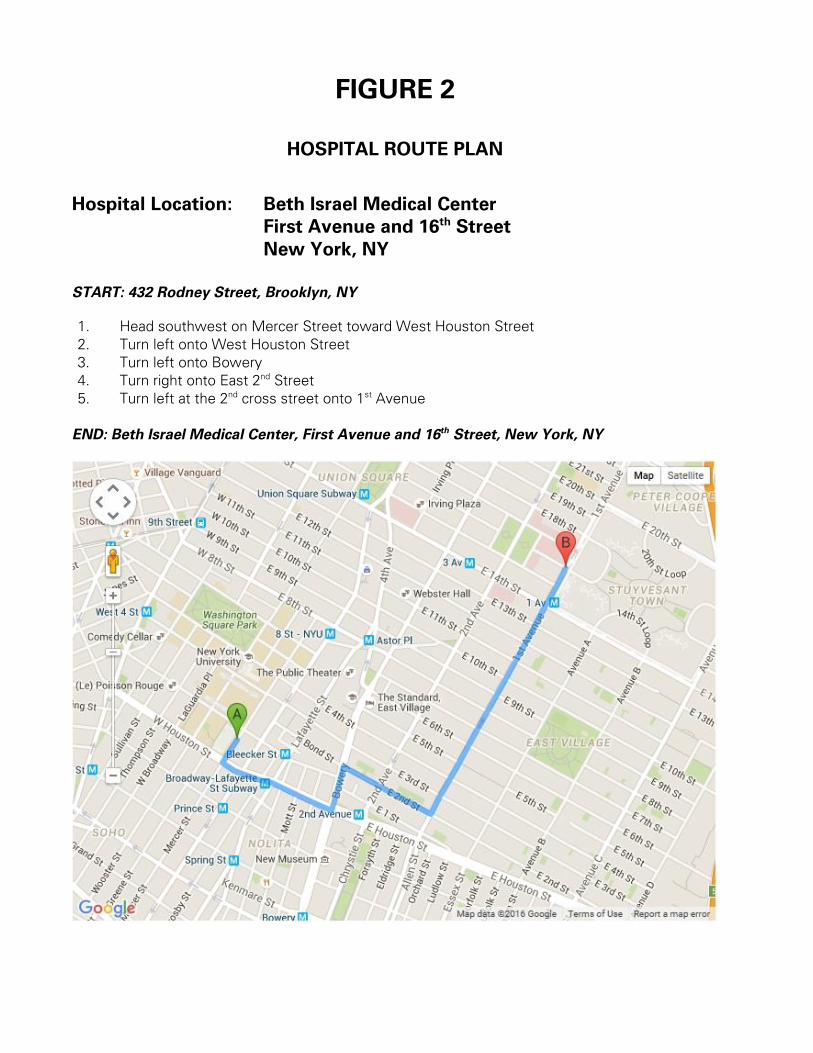
FIGURE 2
HOSPITAL ROUTE PLAN
Hospital Location: Beth Israel Medical Center
First Avenue and 16th Street
New York, NY
START: 432 Rodney Street, Brooklyn, NY
1. Head southwest on Mercer Street toward West Houston Street
2. Turn left onto West Houston Street
3. Turn left onto Bowery
4. Turn right onto East 2nd Street
5. Turn left at the 2nd cross street onto 1st Avenue
END: Beth Israel Medical Center, First Avenue and 16th Street, New York, NY

ATTACHMENT A
STANDING ORDERS
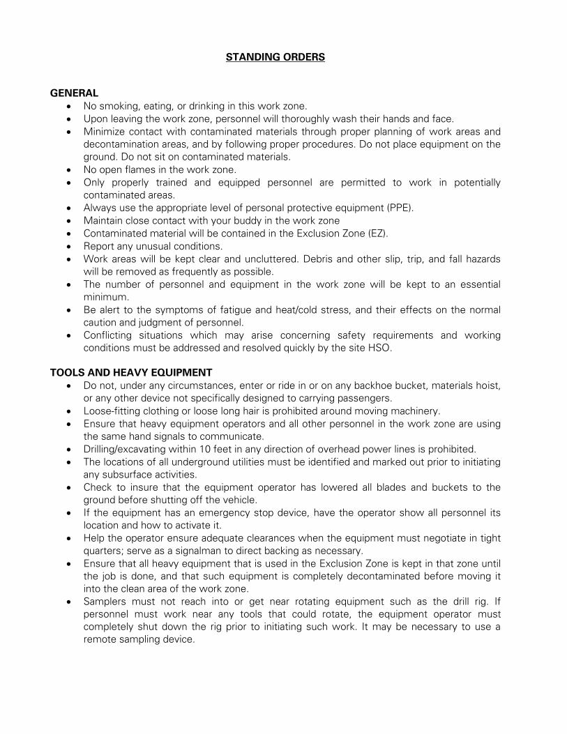
STANDING ORDERS
GENERAL
No smoking, eating, or drinking in this work zone.
Upon leaving the work zone, personnel will thoroughly wash their hands and face.
Minimize contact with contaminated materials through proper planning of work areas and
decontamination areas, and by following proper procedures. Do not place equipment on the
ground. Do not sit on contaminated materials.
No open flames in the work zone.
Only properly trained and equipped personnel are permitted to work in potentially
contaminated areas.
Always use the appropriate level of personal protective equipment (PPE).
Maintain close contact with your buddy in the work zone
Contaminated material will be contained in the Exclusion Zone (EZ).
Report any unusual conditions.
Work areas will be kept clear and uncluttered. Debris and other slip, trip, and fall hazards
will be removed as frequently as possible.
The number of personnel and equipment in the work zone will be kept to an essential
minimum.
Be alert to the symptoms of fatigue and heat/cold stress, and their effects on the normal
caution and judgment of personnel.
Conflicting situations which may arise concerning safety requirements and working
conditions must be addressed and resolved quickly by the site HSO.
TOOLS AND HEAVY EQUIPMENT
Do not, under any circumstances, enter or ride in or on any backhoe bucket, materials hoist,
or any other device not specifically designed to carrying passengers.
Loose-fitting clothing or loose long hair is prohibited around moving machinery.
Ensure that heavy equipment operators and all other personnel in the work zone are using
the same hand signals to communicate.
Drilling/excavating within 10 feet in any direction of overhead power lines is prohibited.
The locations of all underground utilities must be identified and marked out prior to initiating
any subsurface activities.
Check to insure that the equipment operator has lowered all blades and buckets to the
ground before shutting off the vehicle.
If the equipment has an emergency stop device, have the operator show all personnel its
location and how to activate it.
Help the operator ensure adequate clearances when the equipment must negotiate in tight
quarters; serve as a signalman to direct backing as necessary.
Ensure that all heavy equipment that is used in the Exclusion Zone is kept in that zone until
the job is done, and that such equipment is completely decontaminated before moving it
into the clean area of the work zone.
Samplers must not reach into or get near rotating equipment such as the drill rig. If
personnel must work near any tools that could rotate, the equipment operator must
completely shut down the rig prior to initiating such work. It may be necessary to use a
remote sampling device.

ATTACHMENT B
DECONTAMINATION PROCEDURES
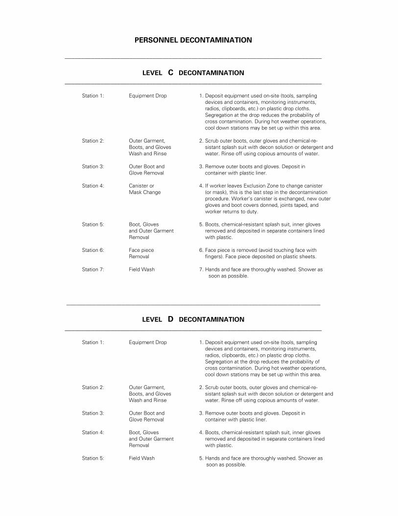
PERSONNEL DECONTAMINATION
_______________________________________________________________________________
LEVEL C DECONTAMINATION
_______________________________________________________________________________
Station 1: Equipment Drop 1. Deposit equipment used on-site (tools, sampling
devices and containers, monitoring instruments,
radios, clipboards, etc.) on plastic drop cloths.
Segregation at the drop reduces the probability of
cross contamination. During hot weather operations,
cool down stations may be set up within this area.
Station 2: Outer Garment, 2. Scrub outer boots, outer gloves and chemical-re-
Boots, and Gloves sistant splash suit with decon solution or detergent and
Wash and Rinse water. Rinse off using copious amounts of water.
Station 3: Outer Boot and 3. Remove outer boots and gloves. Deposit in
Glove Removal container with plastic liner.
Station 4: Canister or 4. If worker leaves Exclusion Zone to change canister
Mask Change (or mask), this is the last step in the decontamination
procedure. Worker’s canister is exchanged, new outer
gloves and boot covers donned, joints taped, and
worker returns to duty.
Station 5: Boot, Gloves 5. Boots, chemical-resistant splash suit, inner gloves
and Outer Garment removed and deposited in separate containers lined
Removal with plastic.
Station 6: Face piece 6. Face piece is removed (avoid touching face with
Removal fingers). Face piece deposited on plastic sheets.
Station 7: Field Wash 7. Hands and face are thoroughly washed. Shower as
soon as possible.
______________________________________________________________________________
LEVEL D DECONTAMINATION
_______________________________________________________________________________
Station 1: Equipment Drop 1. Deposit equipment used on-site (tools, sampling
devices and containers, monitoring instruments,
radios, clipboards, etc.) on plastic drop cloths.
Segregation at the drop reduces the probability of
cross contamination. During hot weather operations,
cool down stations may be set up within this area.
Station 2: Outer Garment, 2. Scrub outer boots, outer gloves and chemical-re-
Boots, and Gloves sistant splash suit with decon solution or detergent and
Wash and Rinse water. Rinse off using copious amounts of water.
Station 3: Outer Boot and 3. Remove outer boots and gloves. Deposit in
Glove Removal container with plastic liner.
Station 4: Boot, Gloves 4. Boots, chemical-resistant splash suit, inner gloves
and Outer Garment removed and deposited in separate containers lined
Removal with plastic.
Station 5: Field Wash 5. Hands and face are thoroughly washed. Shower as
soon as possible.
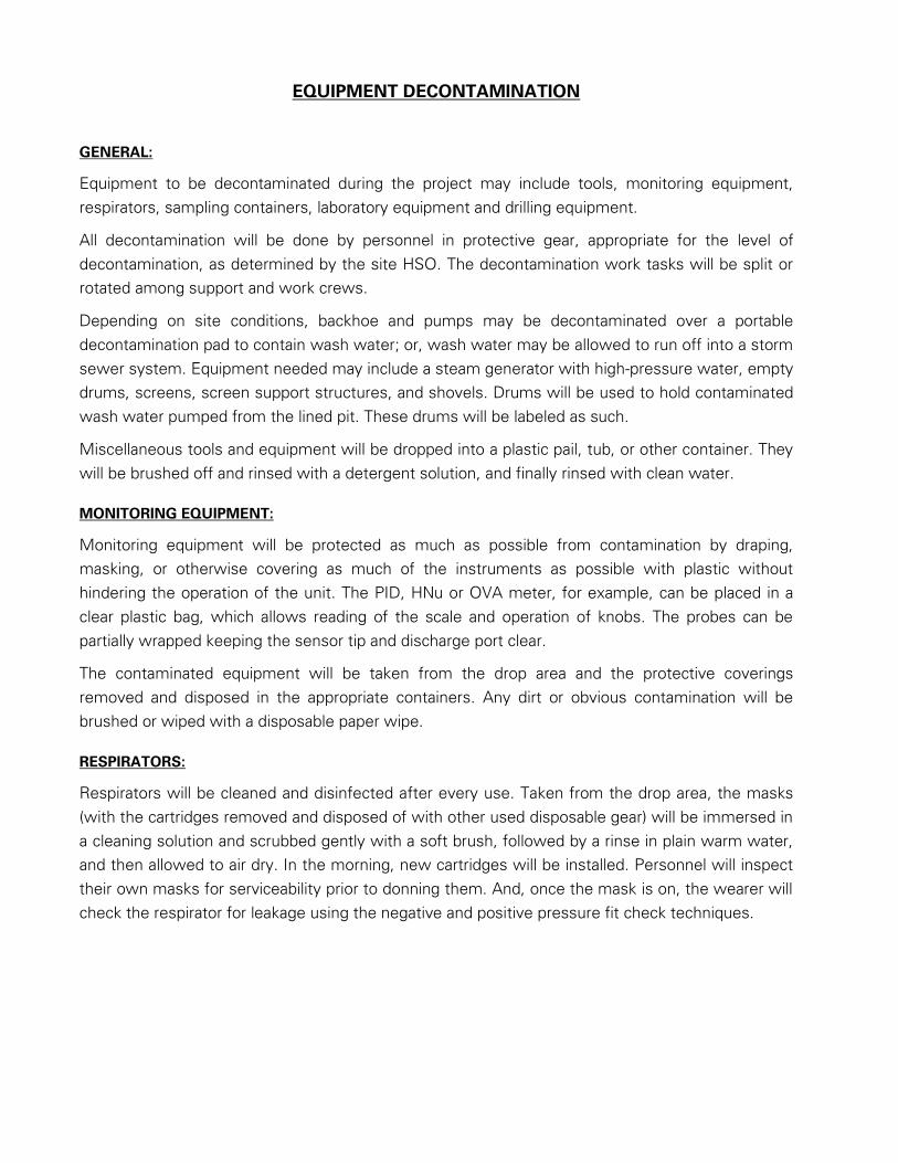
EQUIPMENT DECONTAMINATION
GENERAL:
Equipment to be decontaminated during the project may include tools, monitoring equipment,
respirators, sampling containers, laboratory equipment and drilling equipment.
All decontamination will be done by personnel in protective gear, appropriate for the level of
decontamination, as determined by the site HSO. The decontamination work tasks will be split or
rotated among support and work crews.
Depending on site conditions, backhoe and pumps may be decontaminated over a portable
decontamination pad to contain wash water; or, wash water may be allowed to run off into a storm
sewer system. Equipment needed may include a steam generator with high-pressure water, empty
drums, screens, screen support structures, and shovels. Drums will be used to hold contaminated
wash water pumped from the lined pit. These drums will be labeled as such.
Miscellaneous tools and equipment will be dropped into a plastic pail, tub, or other container. They
will be brushed off and rinsed with a detergent solution, and finally rinsed with clean water.
MONITORING EQUIPMENT:
Monitoring equipment will be protected as much as possible from contamination by draping,
masking, or otherwise covering as much of the instruments as possible with plastic without
hindering the operation of the unit. The PID, HNu or OVA meter, for example, can be placed in a
clear plastic bag, which allows reading of the scale and operation of knobs. The probes can be
partially wrapped keeping the sensor tip and discharge port clear.
The contaminated equipment will be taken from the drop area and the protective coverings
removed and disposed in the appropriate containers. Any dirt or obvious contamination will be
brushed or wiped with a disposable paper wipe.
RESPIRATORS:
Respirators will be cleaned and disinfected after every use. Taken from the drop area, the masks
(with the cartridges removed and disposed of with other used disposable gear) will be immersed in
a cleaning solution and scrubbed gently with a soft brush, followed by a rinse in plain warm water,
and then allowed to air dry. In the morning, new cartridges will be installed. Personnel will inspect
their own masks for serviceability prior to donning them. And, once the mask is on, the wearer will
check the respirator for leakage using the negative and positive pressure fit check techniques.
ATTACHMENT C
EMPLOYEE EXPOSURE/
INJURY INCIDENT REPORT

EMPLOYEE INCIDENT/INJURY REPORT
LANGAN ENGINEERING & ENVIRONMENTAL SERVICES
(Complete and return to Tony Moffa in the Doylestown Office)
Affected Employee Name: Date:
Incident type: Injury Report Only/No Injury
Near Miss Other:
EMPLOYEE INFORMATION (Person completing Form)
Employee Name: Employee No:
Title: Office Location:
Length of time employed or date of hire:
Mailing address:
Sex: M F Birth date:
Business phone & extension: Residence/cell phone:
ACCIDENT INFORMATION
Project: Project #:
Date & time of incident: Time work started & ended:
Site location:
Incident Type: Possible Exposure Exposure Physical Injury
Names of person(s) who witnessed the incident:
Exact location incident occurred:
Describe work being done:

Describe what affected employee was doing prior to the incident occurring:
Describe in detail how the incident occurred:
Nature of the incident (List the parts of the body affected):
Person(s) to whom incident was reported (Time and Date):
List the names of other persons affected during this incident:
Possible causes of the incident (equipment, unsafe work practices, lack of PPE, etc.):
Weather conditions during incident:
MEDICAL CARE INFORMATION
Did affected employee receive medical care? Yes No
If Yes, when and where was medical care received:
Provide name of facility (hospital, clinic, etc.):
Length of stay at the facility?
Did the employee miss any work time? Yes No Undetermined

Date employee last worked: Date employee returned to work:
Has the employee returned to work? Yes No
Does the employee have any work limitations or restrictions from the injury? : Yes No
If Yes, please describe:
Did the exposure/injury result in permanent disability? Yes No Unknown
If Yes, please describe:
HEALTH & SAFETY INFORMATION
Was the operation being conducted under an established site specific CONSTRUCTION CONSTRUCTION
HEALTH AND SAFETY PLAN?
Yes No Not Applicable:
Describe protective equipment and clothing used by the employee:
Did any limitations in safety equipment or protective clothing contribute to or affect exposure / injury? If so,
explain:
Employee Signature Date
Langan Representative Date

ATTACHMENT D
CALIBRATION LOG

DATE:________________ PROJECT:____________________
CALIBRATION LOG
Date &
Time
Inst
Type
Inst #
Media
Initial
Reading
Span #
Calibrat.
Reading
Performed By:
ATTACHMENT E
MATERIAL SAFETY DATA SHEETS
SAFETY DATA SHEETS
All Langan Field Personnel Completing This Work Plan Are To Have Real Time Accessibility
To Material Safety Data Sheet (MSDs) or Safety Data Sheet (SDSs) Through Their Smart
Phone.
The link is http://www.msds.com/
The login name is “drapehead”
The password is “2angan987”
If You Are Unable To Use the Smart Phone App, You Are To Bring Printed Copies of the
MSDs/SDSs to The Site

ATTACHMENT F
JOBSITE SAFETY INSPECTION CHECKLIST
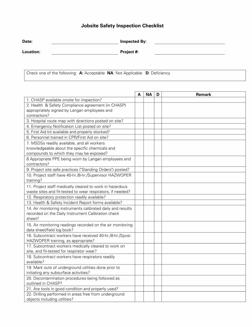
Jobsite Safety Inspection Checklist
Date: Inspected By:
Location: Project #:
Check one of the following: A: Acceptable NA: Not Applicable D: Deficiency
A NA D Remark
1. CHASP available onsite for inspection?
2. Health & Safety Compliance agreement (in CHASP)
appropriately signed by Langan employees and
contractors?
3. Hospital route map with directions posted on site?
4. Emergency Notification List posted on site?
5. First Aid kit available and properly stocked?
6. Personnel trained in CPR/First Aid on site?
7. MSDSs readily available, and all workers
knowledgeable about the specific chemicals and
compounds to which they may be exposed?
8 Appropriate PPE being worn by Langan employees and
contractors?
9. Project site safe practices ("Standing Orders") posted?
10. Project staff have 40-hr./8-hr./Supervisor HAZWOPER
training?
11. Project staff medically cleared to work in hazardous
waste sites and fit-tested to wear respirators, if needed?
12. Respiratory protection readily available?
13. Health & Safety Incident Report forms available?
14. Air monitoring instruments calibrated daily and results
recorded on the Daily Instrument Calibration check
sheet?
15. Air monitoring readings recorded on the air monitoring
data sheet/field log book?
16. Subcontract workers have received 40-hr./8-hr./Spvsr.
HAZWOPER training, as appropriate?
17. Subcontract workers medically cleared to work on
site, and fit-tested for respirator wear?
18. Subcontract workers have respirators readily
available?
19. Mark outs of underground utilities done prior to
initiating any subsurface activities?
20. Decontamination procedures being followed as
outlined in CHASP?
21. Are tools in good condition and properly used?
22. Drilling performed in areas free from underground
objects including utilities?
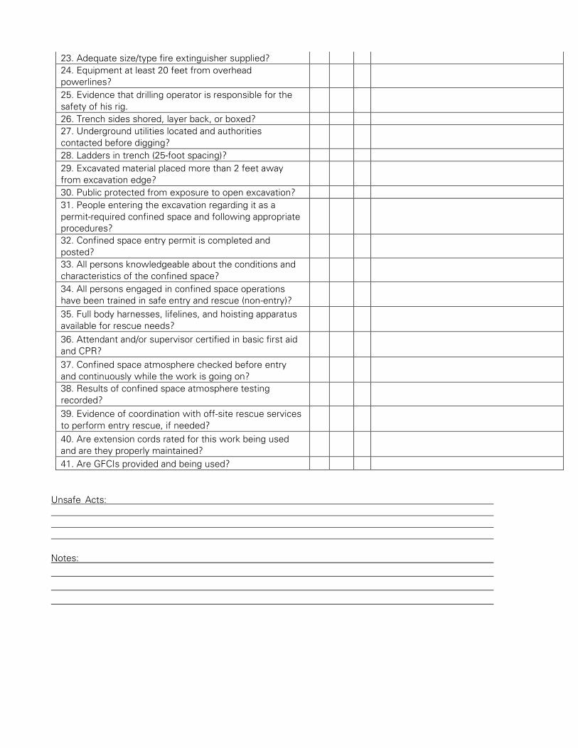
23. Adequate size/type fire extinguisher supplied?
24. Equipment at least 20 feet from overhead
powerlines?
25. Evidence that drilling operator is responsible for the
safety of his rig.
26. Trench sides shored, layer back, or boxed?
27. Underground utilities located and authorities
contacted before digging?
28. Ladders in trench (25-foot spacing)?
29. Excavated material placed more than 2 feet away
from excavation edge?
30. Public protected from exposure to open excavation?
31. People entering the excavation regarding it as a
permit-required confined space and following appropriate
procedures?
32. Confined space entry permit is completed and
posted?
33. All persons knowledgeable about the conditions and
characteristics of the confined space?
34. All persons engaged in confined space operations
have been trained in safe entry and rescue (non-entry)?
35. Full body harnesses, lifelines, and hoisting apparatus
available for rescue needs?
36. Attendant and/or supervisor certified in basic first aid
and CPR?
37. Confined space atmosphere checked before entry
and continuously while the work is going on?
38. Results of confined space atmosphere testing
recorded?
39. Evidence of coordination with off-site rescue services
to perform entry rescue, if needed?
40. Are extension cords rated for this work being used
and are they properly maintained?
41. Are GFCIs provided and being used?
Unsafe Acts:
Notes:

ATTACHMENT G
JOB SAFETY ANALYSIS FORM
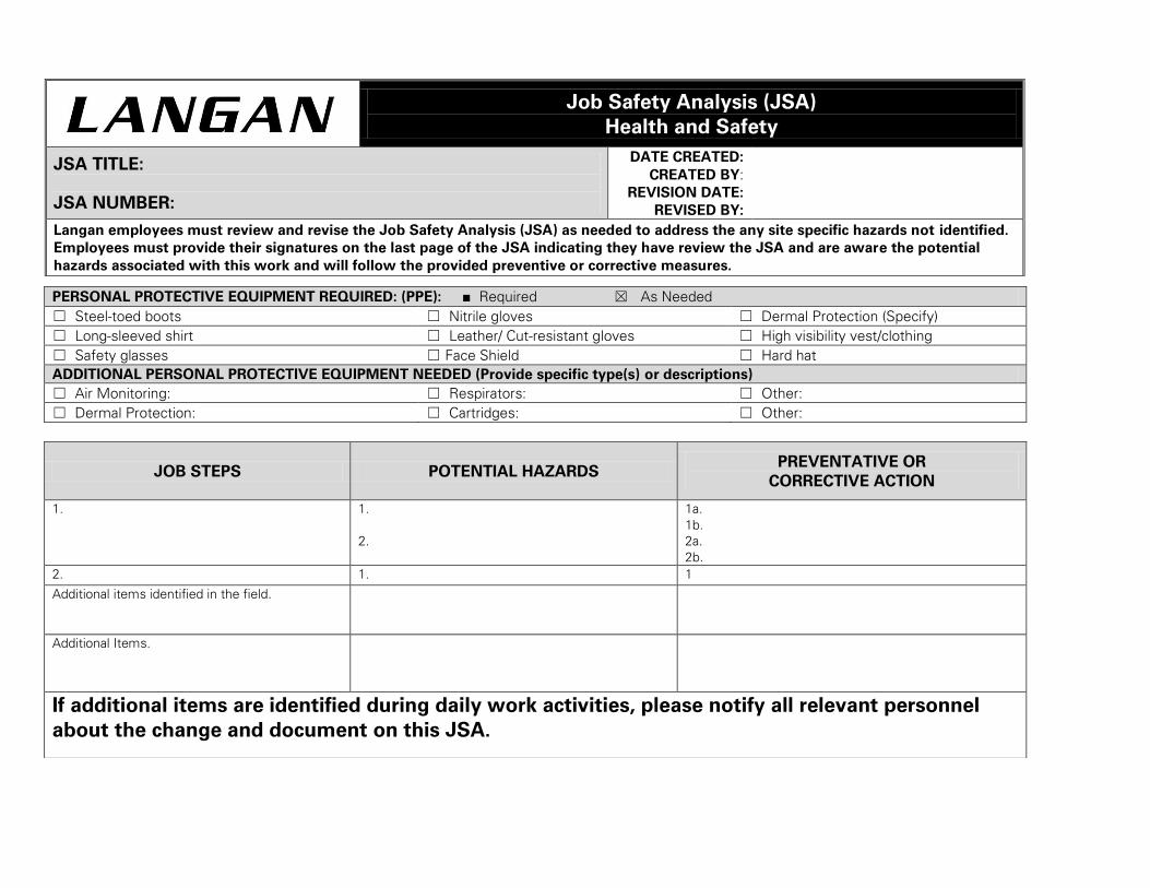
Job Safety Analysis (JSA)
Health and Safety
JSA TITLE:
JSA NUMBER:
DATE CREATED:
CREATED BY:
REVISION DATE:
REVISED BY:
Langan employees must review and revise the Job Safety Analysis (JSA) as needed to address the any site specific hazards not identified.
Employees must provide their signatures on the last page of the JSA indicating they have review the JSA and are aware the potential
hazards associated with this work and will follow the provided preventive or corrective measures.
PERSONAL PROTECTIVE EQUIPMENT REQUIRED: (PPE): ■ Required ☒ As Needed
☐ Steel-toed boots ☐ Nitrile gloves ☐ Dermal Protection (Specify)
☐ Long-sleeved shirt ☐ Leather/ Cut-resistant gloves ☐ High visibility vest/clothing
☐ Safety glasses ☐ Face Shield ☐ Hard hat
ADDITIONAL PERSONAL PROTECTIVE EQUIPMENT NEEDED (Provide specific type(s) or descriptions)
☐ Air Monitoring: ☐ Respirators: ☐ Other:
☐ Dermal Protection: ☐ Cartridges: ☐ Other:
JOB STEPS POTENTIAL HAZARDS PREVENTATIVE OR
CORRECTIVE ACTION
1. 1.
2.
1a.
1b.
2a.
2b.
2. 1. 1
Additional items identified in the field.
Additional Items.
If additional items are identified during daily work activities, please notify all relevant personnel
about the change and document on this JSA.

ATTACHMENT H
TAILGATE SAFETY BRIEFING FORM

LANGAN TAILGATE SAFETY BRIEFING
Date: Time:
Leader: Location:
Work Task:
SAFETY TOPICS (provide some detail of discussion points)
Chemical Exposure Hazards and Control:
Physical Hazards and Control:
Air Monitoring:
PPE:
Communications:
Safe Work Practices:
Emergency Response:
Hospital/Medical Center Location:
Phone Nos.:
Other:
FOR FOLLOW-UP (the issues, responsibilities, due dates, etc.)
ATTENDEES
PRINT NAME COMPANY SIGNATURE