Embed Size (px)
Citation preview

PS-3005 Programable DC Power Supply
(0-30V, 0-5A)
Part of the PS-3000 Series
User Manual
Revision 2013-01
Wavecom Instruments PS-3000 series DC Power Supply User Manual
Page 2
Table of Contents SAFETY INSTRUCTIONS......................3
Safety Symbols ................... 3
Safety Guidelines................. 4
AC Input........................ 4
Environmental Requirements......... 4
Fuse........................... 5
OVERVIEW...................................5
Main Features................... 5
Front Panel Overview.............. 7
Displays.........................8
Status Indicators ................. 8
Front Panel Buttons and Terminals..... 9
Rear Panel Overview............... 11
OPERATION ................................. 12
Power Up........................12
Output ON/OFF.................. 13
Beep ON/OFF.................... 13
Front Panel/Key Lock............... 14
Setting Output Parameters........... 14
Save/Recall Setup................. 16
REMOTE CONTROL......................... 17
FAQ......................................... 19
SPECIFICATIONS ........................... 20

Wavecom Instruments PS-3000 series DC Power Supply User Manual
Page 3
SAFETY INSTRUCTIONS
This chapter contains important safety instructions that you must follow when operating the PS-3000 series and when keeping it in storage. Read the following before any operation to ensure your safety and to keep the product in the best condition.
Safety Symbols
These safety symbols may appear in this manual or on the series.
WARNING
DANGER High Voltage
Earth (Ground) Terminal
Wavecom Instruments PS-3000 series DC Power Supply User Manual
Page 4
Safety Guidelines
Do not block or obstruct the cooling fan and side vent
openings. Provide free space of at least 2.5cm.
Avoid rough handling to prevent damages.
Avoid discharging static electricity to output terminals.
The ESD safety precautions must be observed during
installation and operation.
To avoid the risk of electric shock do not attempt to
open the unit, no serviceable parts inside.
Use only power cord supplied with the unit or a cord
approved for this type of appliance. The protective
grounding conductor of the AC power cord must be
connected to ground to provide protection against
electric shock.
AC Input
AC Input Voltage: 240V, 50 Hz The power cord must be connected to an earthed
mains outlet/power point.
Environmental Requirements
Operation
Location: Indoor only, no direct sunlight and dust-free.
Pollution degree 2, normally non-conductive.
Temperature Rating: 0-40°C

Wavecom Instruments PS-3000 series DC Power Supply User Manual
Page 5
Relative Humidity (non-condensing): <80%
Altitude: <2000m above sea level
Storage
Location: Indoor
Relative Humidity: <80% Temperature: 0-60°C
FUSE
PS-3005D and PS3005P: T3A/250V To avoid fire hazard replace the fuse only with the
specified type and rating as per rating label. Disconnect the power cord before fuse replacement. Make sure the cause of fuse blowout is fixed before
fuse replacement.
OVERVIEW
Main Features
Model V Display A Display USB/RS Resolution
PS-3005D 4 digit 4 digit NO 10mV/1mA PS-3005P 4 digit 4 digit YES 10mV/1mA
Wavecom Instruments PS-3000 series DC Power Supply User Manual
Page 6
Performance
Low noise, the cooling fan speed is adjusted
proportionally to the heatsink temperature.
Compact size, light weight.
Operation Constant Voltage or Constant Current operation.
Output On/Off control
Voltage and Current digital display
Memory function, up to 5 voltage/current settings can
be stored.
Coarse and Fine Voltage/Current adjustments from 0
to 30V and from 0 to 5A.
Software controlled output setting through RS232 or
USB port on P models
Beep on front panel button pressing (except LOCK
button) with On/Off option
Key lock
Protection Overcurrent (OCP) and output overvoltage protection
(OVC).
Interfaces USB compatible and RS 232 for remote control via
PC, P models only.
Wavecom Instruments PS-3000 series DC Power Supply User Manual
Page 7
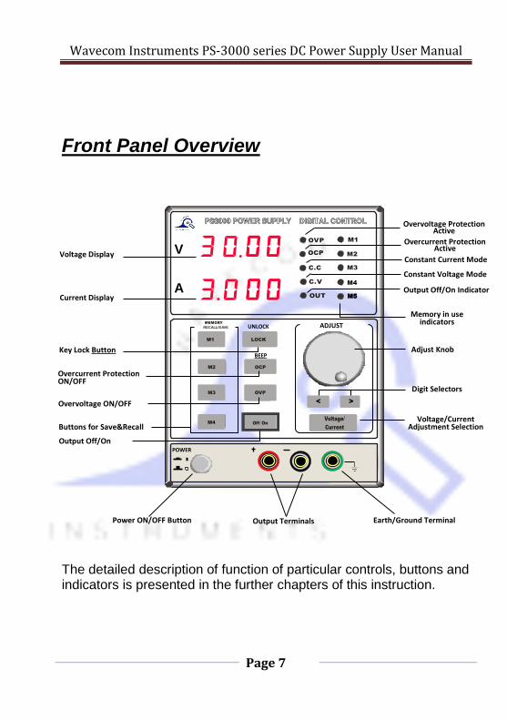
M3 < >
>
M2
M4
M1 LOCK
OCP
OVP
Front Panel Overview
The detailed description of function of particular controls, buttons and indicators is presented in the further chapters of this instruction.
ADJUST
M4
M5 M5
V
A
Adjust Knob
Digit Selectors
Voltage/Current Adjustment Selection
Earth/Ground Terminal
POWER
Output Terminals
MEMORY
RECALL/SAVE
Memory in use indicators
Overvoltage Protection Active
Overcurrent Protection Active
Constant Current Mode
Constant Voltage Mode
Output Off/On Indicator
Power ON/OFF Button
Buttons for Save&Recall
Output Off/On
Overvoltage ON/OFF
Overcurrent Protection ON/OFF
Key Lock Button
Voltage Display
Current Display
UNLOCK
BEEP
Wavecom Instruments PS-3000 series DC Power Supply User Manual
Page 8
Displays
Voltage: Displays the set value of the output voltage when output is switched off. It displays the actual output voltage when the output is on
Current: Displays the set value of the output current when output is switched off. It displays the actual output current when the output is on.
Status Indicators
OVP indicates the state of the overvoltage protection.
When this function is turned on the indicator is
illuminated. When the output voltage is higher than the
set value due to abnormal conditions the output is
switched off and OVP indicator flickers. The
OVP button is to be pressed to recover the supply to its
previous state
OCP indicates the state of the overcurrent protection.
When this function is turned on the indicator is
illuminated.
C.C is the constant current mode indicator. When power
supply is in this mode the C.C indicator is on.
C.V is constant voltage mode indicator. When power
supply is in this mode the C.V indicator is on.

Wavecom Instruments PS-3000 series DC Power Supply User Manual
Page 9
MEMORY
RECALL/SAVE
M1
M2
M3
M4
OUT is output state indicator. If it is ON there is
voltage/current present between output terminals.
Front Panel Buttons and Terminals
Save or recall front panel settings. Four memory
locations are available through buttons M1-M4. The
fifth is accessible by rotating the ADJUST knob
clockwise while the M4 location is being used. For
details refer to page 16.
LOCK
UNLOCK
OCP
BEEP
Front panel key lock function. For details refer to page
14.
Dual function button. Single pressure toggles the
Overcurrent protection function On/Off. If depressed
and held for longer than 2 seconds it toggles the Beep
function On/Off.
Indicate which memory location is being used

Wavecom Instruments PS-3000 series DC Power Supply User Manual
Page 10
ADJUST
< >
Voltage/
Current
OVP
Off/On
Switches the Overvoltage protection On/Off
Switches the output Off/On.
Knob for Voltage/Current adjustment. Rotating
clockwise increases the value.
Digit Selection buttons. Pressing the < key shifts
selection the left, > key shifts selection to the right.
POWER
Voltage Current adjustment selection button.
Default is Voltage.
On/Off Power Switch. Power is ON when
switch is pressed.
Output Terminals, 4mm banana sockets for
4mm banana plugs. The red terminal is positive
(+) terminal and the black one negative (-).
None of them is internally connected to mains
Earth/Ground.
Ground/Earth Terminal, connected to mains
supply earth.

Wavecom Instruments PS-3000 series DC Power Supply User Manual
Page 11
Cooling fan
and fan vents
Rear Panel Overview
DO NOT REMOVE COVERS; SERVICING TO QUALIFIED
WARNING VOLTAGE RATING: AC 240V
FUSE RATING: 2A/250V
Rating Label
IEC Power
Socket
USB socket for connecting to PC USB port.
RS232 socket for connecting to PC RS232 port.
Fused Appliance Inlet/Power Socket
Communication
Ports

Wavecom Instruments PS-3000 series DC Power Supply User Manual
Page 12
OPERATION
Manual Operation D and P models.
During manual operation the power supply is NOT connected to the PC.
Connect AC power cord of a proper type between the IEC socket on the
back panel and mains supply outlet rated as per voltage/fuse rating label.
Power up.
Press the POWER button in the front panel to switch the power
supply ON.
The displays initialize showing the settings from the M1 memory
location, the M1 indicator is on.
The OVP, OCP, C.C, C.V and OUT indicators are off. To switch the
power supply off press the POWER button again.
Note: By default the output is off after power up.
Before the fuse replacement make sure power
cord is disconnected from the power supply.
Ensure the correct type of the fuse is used, refer
to rating label and ‘Fuse’ chapter on page 6.

Wavecom Instruments PS-3000 series DC Power Supply User Manual
Page 13
Output On/Off Press the On/Off button to turn the output ON.
Now the voltage as set in the memory M1 is present between (+)
and (-) terminals.
If a load was connected to the supply the value of the output
current is shown on the A display. If no load was connected the A
display shows all zeros. Pressing the Off/On button again switches
the output off.
Note: The output will automatically switch off if any of the following
conditions occur:
1. OVP function is activated and the measured output voltage
exceeds the set voltage due to external reasons.
2. Any memory M1-M4 button is pressed or ADJUST knob rotated
clockwise while M4 memory location is in use.
Beep On/Off By default the beep function is enabled. To turn off the beep:
Press the OCP (BEEP) button for at least 2 seconds until a short
beep is heard.
The function is now turned off.
To activate this function press and hold the same button for at
least 2 seconds until a long beep is heard.
The state of this function is one of the parameters stored in the internal
memory, common for all locations M1-M5.
Note: Pressing and holding the OCP button to disable the beep function
toggles the OCP function On/Off as well.

Wavecom Instruments PS-3000 series DC Power Supply User Manual
Page 14
Front Panel/Key Lock Press and hold the LOCK button for at least 2 seconds.
A successful locking is confirmed by a long beep.
All the function buttons and the ADJUST knob are then disabled.
Unlocking is done by pressing the LOCK button again for at least
two seconds.
The unlocking is confirmed by a short beep.
Note: Locking is not switching the output off.
Setting Output Parameters 1. Select the memory location for which the settings are to be defined
following instructions in Save/Recall Setup section. 2. With output switched off press the Voltage/Current selection
button to set the output voltage. One of the digits in the V display will flash. By default this is the second digit from the left.
3. Adjust the voltage to the required value by rotating the ADJUST
knob. The precision of adjustment can be changed by selecting
digits in the voltage readout with the < and > buttons. Rotating the knob clockwise increases the value while anticlockwise- decreases.
In the constant voltage mode (CV) the set value is the desired output voltage.
In the constant current mode (CC) this is the output voltage limit.
With over-voltage protection (OVP) ON the output switches off if the voltage exceeds this value.
4. Press the Voltage/Current button again to adjust the current. Now

Wavecom Instruments PS-3000 series DC Power Supply User Manual
Page 15
a digit in the A display will start flashing. Set the current using the same procedure as for voltage adjustment.
In the constant voltage mode (CV) the set value is the current limit.
In the constant current mode (CC) this is the output current.
With over-current protection (OVP) on the output switches off if the current exceeds this value.
5. Press the memory button again or alternatively wait until the
display stops flashing a digit. In case of M5 just wait for the display to stop flashing. Pressing the Off/On button will save the setting as well.
Note 1: Adjustments of the voltage and current values is possible with the
output on. In this case the output voltage or current will change on
adjustment. However, pressing any of the M1-M4 buttons will
store the final values but the output will be switched off.
Note 2: If the current was set to 0 the output will not switch on upon
pressing the Off/On button.
Constant Voltage and Constant Current operation.
When the output current does not exceed the set value the power
supply works in the constant voltage mode (C.V) with the output
voltage as set and the output current depending on the impedance
of the load connected. The C.V indicator is ON.
When the load is causing the output current to exceed the set
value the power supply switches into constant current mode (C.C)
with the output current as set and the output voltage depending
on the impedance of the load connected. The C.C indicator is ON.

Wavecom Instruments PS-3000 series DC Power Supply User Manual
Page 16
Note: If the OCP function is switched ON the supply does not change to C.C
mode but is switching the output off instead.
Save/recall setup The following settings can be stored in one of fife memories:
Output voltage and current
Beep function state, on or off (for M1-M5)
The following settings are not saved. Their default state on power up is off.
Output on/off
Key Lock on/off
OCP and OVP on/off
Position of the digit to be adjusted first.
1. To select the memory to be used for save/recall press one of the
M1-M4 buttons. The corresponding M1-M4 indicator will come on
and the parameters stored in this location will be recalled. Their
values can be then changed using the procedure outlined above in
Setting Output Parameters.
2. To select memory M5 select the M4 first by pressing M4 button
then rotate the ADJUST knob clockwise. The M5 indicator will
come on. The parameters stored in this location will be recalled
and their adjustment possible.
Note: Recalling values from any memory location switches the output off.

Wavecom Instruments PS-3000 series DC Power Supply User Manual
Page 17
Remote Control
The model with suffix P can be controlled via PC through USB or RS232
interface. The USB and RS 232 ports are located on the back of the supply.
For RS232 control the setting of the appropriate COM port is as follows:
Baud rate : 9600
Parity bit: None
Data bits: 8
Stop bits: 1
Data flow control: None 1. Connect the RS232 or USB ports on the power supply to PC using
RS232 or USB cable. (RS232 cable not provided).
2. Switch the power supply on. It will automatically establish
connection - if successful a beep will be audible. Use the pre-
installed PC software to set the power supply parameters.
Note: When the connection with PC is established the front panel is
locked, button functions are not accessible and the power supply is
controlled from PC only.
3. To exit from the Remote Control mode close the remote control
application and disconnect the USB/RS 232 cable from the port on
the power supply. The power supply will disconnect and a beep will
confirm a successful disconnection. Then it switches itself into
manual mode and unlocks the front panel.
Wavecom Instruments PS-3000 series DC Power Supply User Manual
Page 18
Functionality check.
Run this query command via the PC terminal application such as MTTTY
(Multi-threaded TTY):
*Idn
This should return the identification information like:
manufacturer and model name, serial number, version number in format:
PS3005, SN: XXXXXXXX, V.XX
Remote control PC application.
For details on installation and operation of the PC software refer to the
used guide included with the software (for P model only).

Wavecom Instruments PS-3000 series DC Power Supply User Manual
Page 19
FAQ
Q1: The panel buttons don’t work after power on but the V and A
displays are ON.
A1: The front panel is locked. Press and hold the LOCK button for at
least 2 seconds, until a short beep is heard.
Q2: No output after pressing Off/On button with supply powered on
and displays working.
A2: Current is set to 0.
Q3: Output voltage rises slowly after pressing the Off/On button
A3: No load connected or the set current is too small.
Q4: Output switches automatically off after pressing Off/On button
with OCP function activated.
A4: OCP value is set too low for particular load connected. Adjust the
OCP current and then press Off/On button.

Wavecom Instruments PS-3000 series DC Power Supply User Manual
Page 20
SPECIFICATION Note: The specifications below are valid under test temperature of
25°C±5°C and after power supply warm-up for at least 20
minutes.
Model PS-3005D/P
Voltage Range 0-30V
Current Range 0-5A Load Regulation
Voltage ≤ 0.01%+2mV
Current ≤ 0.1%+10mA
Line Regulation
Voltage ≤ 0.01%+3mV
Current ≤ 0.1%+3mA
Setup Resolution
Voltage 10mV
Current 1mA
Setup Accuracy(25℃+-5℃)
Voltage ≤ 0.5%+20mV
Current ≤ 0.5%+10mA
Ripple(20Hz-20MHz)
Voltage ≤2mV rms
Current ≤3mA rms T
Voltage ≤100ppm+10mV
Current ≤100ppm+5mA
Read Back Accuracy

Wavecom Instruments PS-3000 series DC Power Supply User Manual
Page 21
Voltage 10mV
Current 1mA
Read Back T
Voltage ≤100ppm+10mV
Current ≤100ppm+5mA
Wavecom Instruments PS-3000 series DC Power Supply User Manual
Page 22
Wavecom Instruments Pty Ltd
Adelaide
257 Grange Road
FINDON SA 5023
Ph: (+61) 08 8243 3500 Fax: (+61) 08 8243 3501
Email: [email protected]
Web: www.wavecom.com.au
Melbourne
772A Station Street
BOX HILL VIC 3128
Ph: (+61) 03 9897 4711
Fax: (+61) 03 9897 4766
Email: [email protected]
Web: www.wavecom.com.au