Embed Size (px)
Citation preview
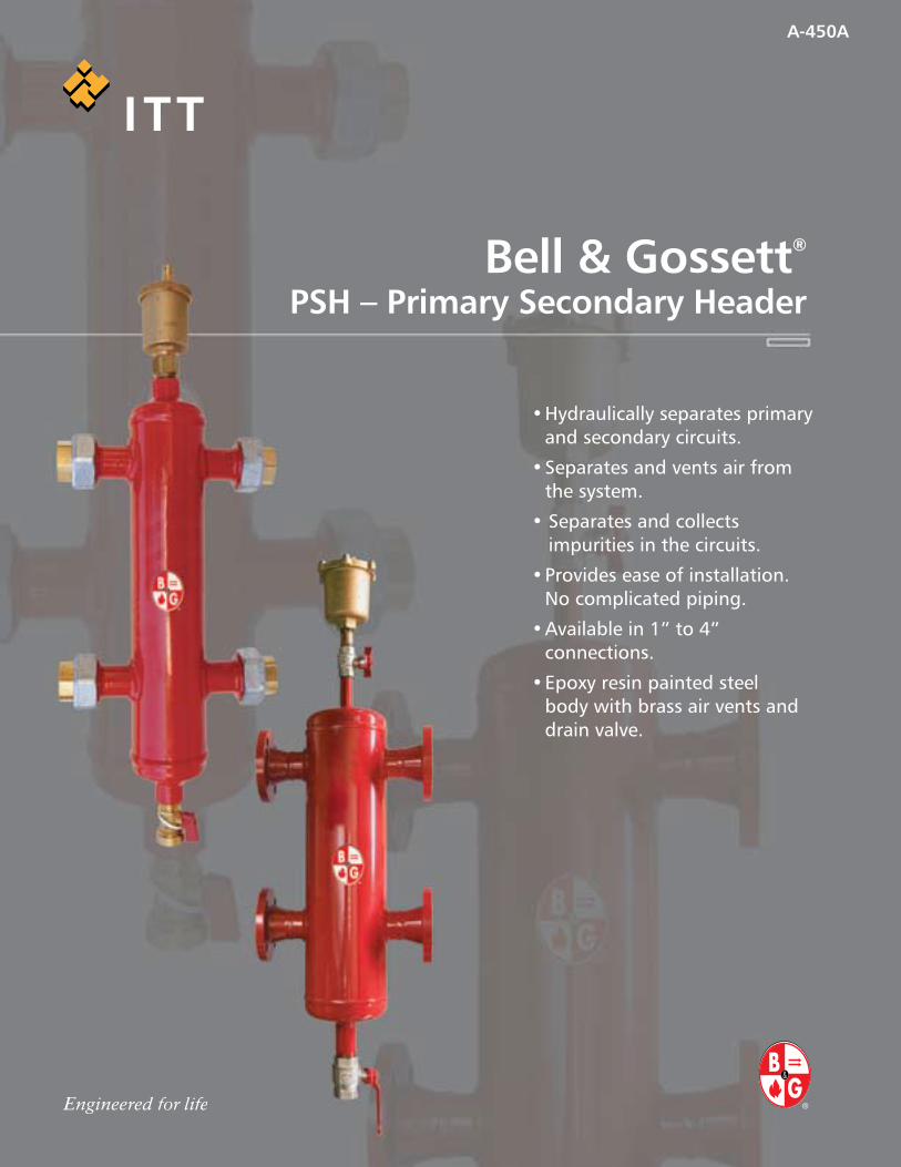
Bell & Gossett® PSH – Primary Secondary Header
A-450A
•Hydraulicallyseparatesprimaryandsecondarycircuits.
•Separatesandventsairfromthesystem.
•Separatesandcollectsimpuritiesinthecircuits.
•Provideseaseofinstallation.Nocomplicatedpiping.
•Availablein1”to4”connections.
•Epoxyresinpaintedsteelbodywithbrassairventsanddrainvalve.
OperatingDataWithInsulation
Workingpressure:150PSIOperatingtemperatureThreaded:32°-210°FOperatingtemperatureFlanged:32°-220°F
WithoutInsulationWorkingpressure:150PSIOperatingtemperatureThreadedandFlanged:32°-230°F
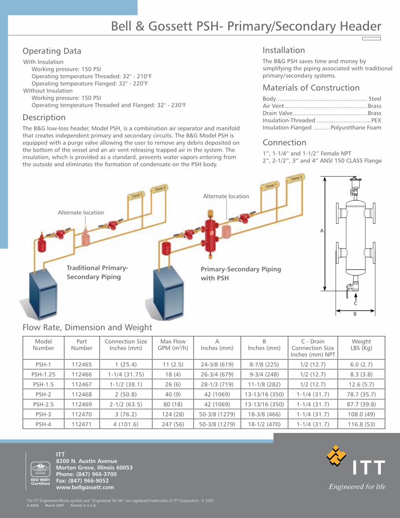
DescriptionTheB&Glow-lossheader,ModelPSH,isacombinationairseparatorandmanifoldthatcreatesindependentprimaryandsecondarycircuits.TheB&GModelPSHisequippedwithapurgevalveallowingtheusertoremoveanydebrisdepositedonthebottomofthevesselandanairventreleasingtrappedairinthesystem.Theinsulation,whichisprovidedasastandard,preventswatervaporsenteringfromtheoutsideandeliminatestheformationofcondensateonthePSHbody.
FlowRate,DimensionandWeight
ModelNumber
PartNumber
ConnectionSizeInches(mm)
MaxFlowGPM(m3/h)
AInches(mm)
BInches(mm)
C-DrainConnectionSizeInches(mm)NPT
WeightLBS(Kg)
PSH-1 112465 1(25.4) 11(2.5) 24-3/8(619) 8-7/8(225) 1/2(12.7) 6.0(2.7)
PSH-1.25 112466 1-1/4(31.75) 18(4) 26-3/4(679) 9-3/4(248) 1/2(12.7) 8.3(3.8)
PSH-1.5 112467 1-1/2(38.1) 26(6) 28-1/3(719) 11-1/8(282) 1/2(12.7) 12.6(5.7)
PSH-2 112468 2(50.8) 40(9) 42(1069) 13-13/16(350) 1-1/4(31.7) 78.7(35.7)
PSH-2.5 112469 2-1/2(63.5) 80(18) 42(1069) 13-13/16(350) 1-1/4(31.7) 87.7(39.8)
PSH-3 112470 3(76.2) 124(28) 50-3/8(1279) 18-3/8(466) 1-1/4(31.7) 108.0(49)
PSH-4 112471 4(101.6) 247(56) 50-3/8(1279) 18-1/2(470) 1-1/4(31.7) 116.8(53)
Primary-Secondary Piping with PSH
Alternatelocation
ITT
8200 N. Austin Avenue Morton Grove, Illinois 60053 Phone: (847) 966-3700 Fax: (847) 966-9052 www.bellgossett.com
The ITT Engineered Blocks symbol and “Engineered for life” are registered trademarks of ITT Corporation. © 2007A-450AMarch2007PrintedinU.S.A.
Bell&GossettPSH-Primary/SecondaryHeader
MaterialsofConstructionBody...................................................... SteelAirVent.................................................BrassDrainValve............................................BrassInsulation-Threaded................................PEXInsulation-Flanged..........PolyurethaneFoam
Connection1”,1-1/4”and1-1/2”FemaleNPT2”,2-1/2”,3”and4”ANSI150CLASSFlange
B
A
C
Traditional Primary-Secondary Piping
Alternatelocation
InstallationTheB&GPSHsavestimeandmoneybysimplifyingthepipingassociatedwithtraditionalprimary/secondarysystems.
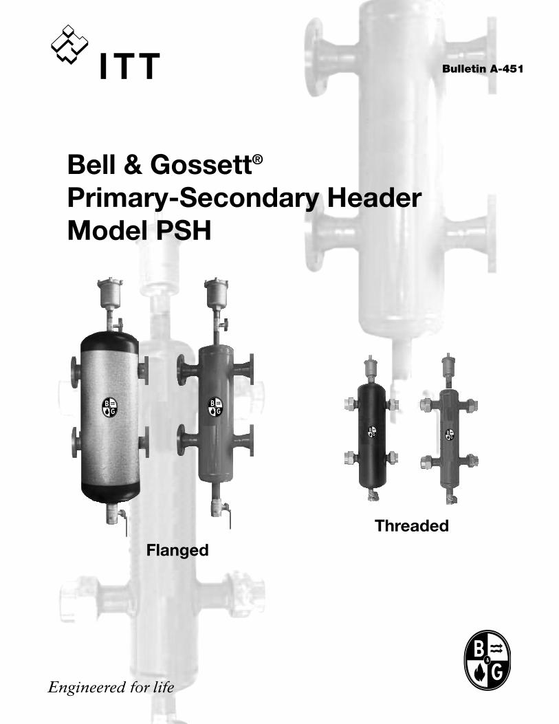
Bulletin A-451
Bell & Gossett®
Primary-Secondary HeaderModel PSH
FlangedThreaded
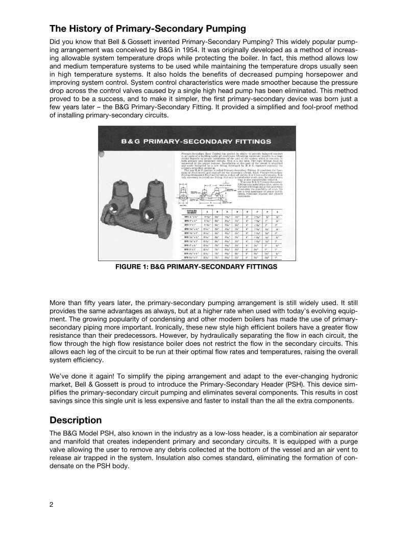
The History of Primary-Secondary PumpingDid you know that Bell & Gossett invented Primary-Secondary Pumping? This widely popular pump-ing arrangement was conceived by B&G in 1954. It was originally developed as a method of increas-ing allowable system temperature drops while protecting the boiler. In fact, this method allows lowand medium temperature systems to be used while maintaining the temperature drops usually seenin high temperature systems. It also holds the benefits of decreased pumping horsepower andimproving system control. System control characteristics were made smoother because the pressuredrop across the control valves caused by a single high head pump has been eliminated. This methodproved to be a success, and to make it simpler, the first primary-secondary device was born just afew years later – the B&G Primary-Secondary Fitting. It provided a simplified and fool-proof methodof installing primary-secondary circuits.
More than fifty years later, the primary-secondary pumping arrangement is still widely used. It stillprovides the same advantages as always, but at a higher rate when used with today’s evolving equip-ment. The growing popularity of condensing and other modern boilers has made the use of primary-secondary piping more important. Ironically, these new style high efficient boilers have a greater flowresistance than their predecessors. However, by hydraulically separating the flow in each circuit, theflow through the high flow resistance boiler does not restrict the flow in the secondary circuits. Thisallows each leg of the circuit to be run at their optimal flow rates and temperatures, raising the overallsystem efficiency.
We’ve done it again! To simplify the piping arrangement and adapt to the ever-changing hydronicmarket, Bell & Gossett is proud to introduce the Primary-Secondary Header (PSH). This device sim-plifies the primary-secondary circuit pumping and eliminates several components. This results in costsavings since this single unit is less expensive and faster to install than the all the extra components.
DescriptionThe B&G Model PSH, also known in the industry as a low-loss header, is a combination air separatorand manifold that creates independent primary and secondary circuits. It is equipped with a purgevalve allowing the user to remove any debris collected at the bottom of the vessel and an air vent torelease air trapped in the system. Insulation also comes standard, eliminating the formation of con-densate on the PSH body.
2
FIGURE 1: B&G PRIMARY-SECONDARY FITTINGS
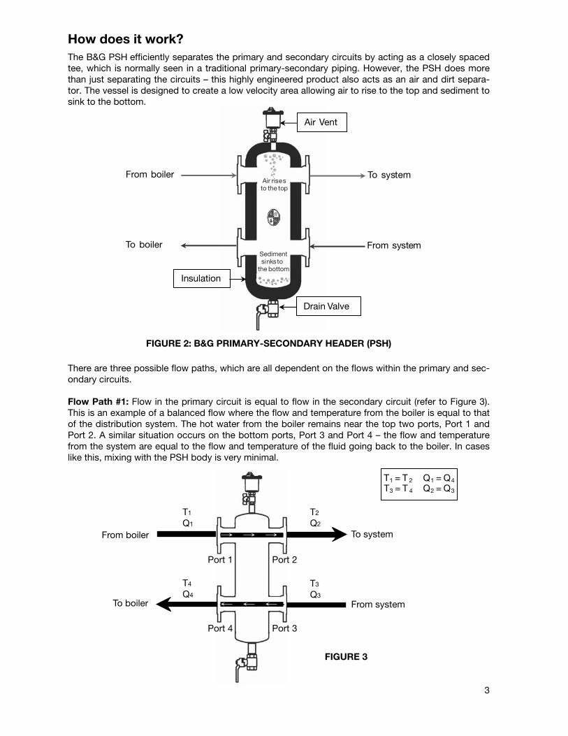
How does it work?The B&G PSH efficiently separates the primary and secondary circuits by acting as a closely spacedtee, which is normally seen in a traditional primary-secondary piping. However, the PSH does morethan just separating the circuits – this highly engineered product also acts as an air and dirt separa-tor. The vessel is designed to create a low velocity area allowing air to rise to the top and sediment tosink to the bottom.
There are three possible flow paths, which are all dependent on the flows within the primary and sec-ondary circuits.
Flow Path #1: Flow in the primary circuit is equal to flow in the secondary circuit (refer to Figure 3).This is an example of a balanced flow where the flow and temperature from the boiler is equal to thatof the distribution system. The hot water from the boiler remains near the top two ports, Port 1 andPort 2. A similar situation occurs on the bottom ports, Port 3 and Port 4 – the flow and temperaturefrom the system are equal to the flow and temperature of the fluid going back to the boiler. In caseslike this, mixing with the PSH body is very minimal.
From boiler To system
From system To boiler Sedimentsinks to
the bottom
Air rises to the top
Air Vent
Drain Valve
Insulation
FIGURE 2: B&G PRIMARY-SECONDARY HEADER (PSH)
T1 = T 2 Q1 = Q4
T3 = T 4 Q2 = Q3
From boiler
To boiler
T1
Q1
T2
Q2
T3
Q3
T4
Q4
To system
From system
Port 1 Port 2
Port 4 Port 3
FIGURE 3
3
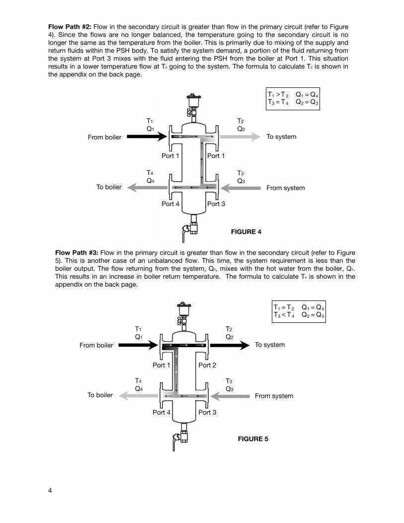
Flow Path #2: Flow in the secondary circuit is greater than flow in the primary circuit (refer to Figure4). Since the flows are no longer balanced, the temperature going to the secondary circuit is nolonger the same as the temperature from the boiler. This is primarily due to mixing of the supply andreturn fluids within the PSH body. To satisfy the system demand, a portion of the fluid returning fromthe system at Port 3 mixes with the fluid entering the PSH from the boiler at Port 1. This situationresults in a lower temperature flow at T2 going to the system. The formula to calculate T2 is shown inthe appendix on the back page.
>
From boiler
To boiler
T1
Q1
T2
Q2
T3
Q3
T4
Q4
To system
From system
T1 T 2 Q1 = Q4
T3 = T 4 Q2 = Q3
Port 1 Port 1
Port 4 Port 3
FIGURE 4
Flow Path #3: Flow in the primary circuit is greater than flow in the secondary circuit (refer to Figure5). This is another case of an unbalanced flow. This time, the system requirement is less than the boiler output. The flow returning from the system, Q3, mixes with the hot water from the boiler, Q1.This results in an increase in boiler return temperature. The formula to calculate T4 is shown in theappendix on the back page.
<
From boiler
To boiler
T1
Q1
T2
Q2
T3
Q3
T4
Q4
To system
From system
T1 T 2 Q1 = Q4
T3 =
T 4 Q2 = Q3
Port 1 Port 2
Port 4 Port 3
FIGURE 5
4
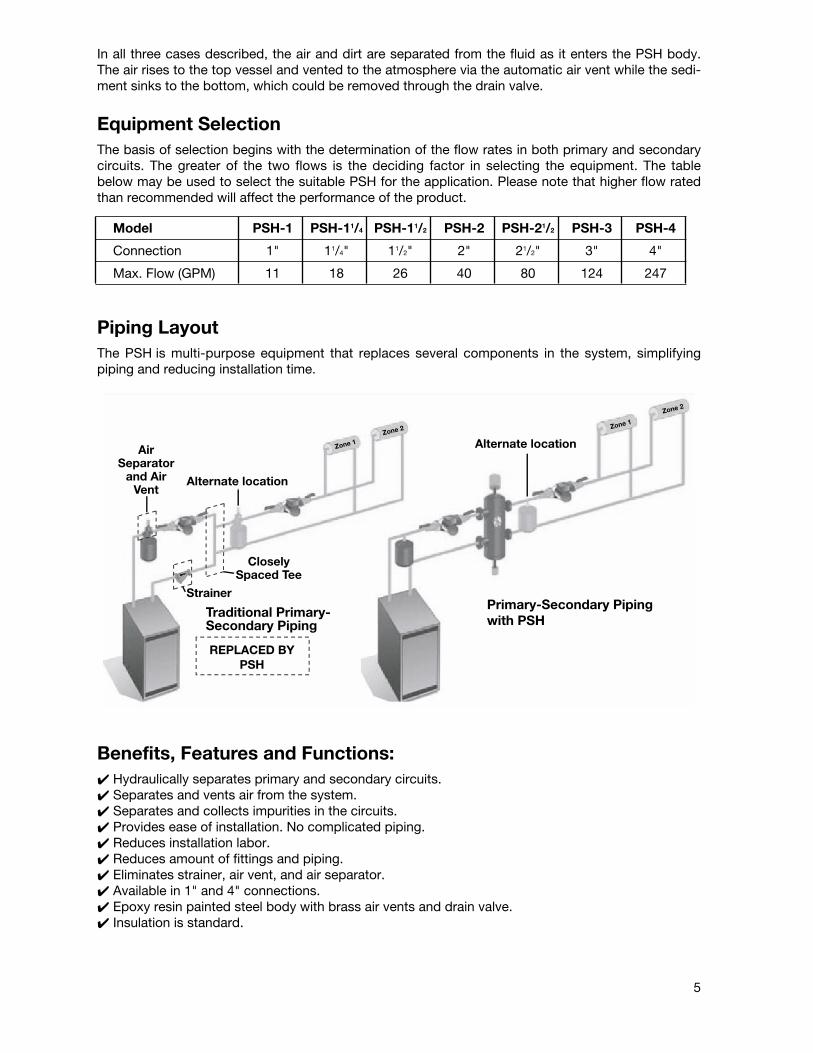
In all three cases described, the air and dirt are separated from the fluid as it enters the PSH body.The air rises to the top vessel and vented to the atmosphere via the automatic air vent while the sedi-ment sinks to the bottom, which could be removed through the drain valve.
Equipment SelectionThe basis of selection begins with the determination of the flow rates in both primary and secondarycircuits. The greater of the two flows is the deciding factor in selecting the equipment. The tablebelow may be used to select the suitable PSH for the application. Please note that higher flow ratedthan recommended will affect the performance of the product.
Model PSH-1 PSH-11/4 PSH-11/2 PSH-2 PSH-21/2 PSH-3 PSH-4
Connection 1" 11/4" 11/2" 2" 21/2" 3" 4"
Max. Flow (GPM) 11 18 26 40 80 124 247
Piping LayoutThe PSH is multi-purpose equipment that replaces several components in the system, simplifyingpiping and reducing installation time.
Benefits, Features and Functions:✔ Hydraulically separates primary and secondary circuits.✔ Separates and vents air from the system.✔ Separates and collects impurities in the circuits.✔ Provides ease of installation. No complicated piping.✔ Reduces installation labor.✔ Reduces amount of fittings and piping.✔ Eliminates strainer, air vent, and air separator.✔ Available in 1" and 4" connections.✔ Epoxy resin painted steel body with brass air vents and drain valve.✔ Insulation is standard.
REPLACED BY PSH
AirSeparator
and AirVent
Strainer
CloselySpaced Tee
Alternate location
Alternate location
Primary-Secondary Pipingwith PSHTraditional Primary-
Secondary Piping
Zone 1Zone 2
Zone 2
Zone 1
Primary-Secondary Pipingwith PSH
Alternate location
5
ITT8200 N. Austin AvenueMorton Grove, IL 60053Phone: (847) 966-3700Fax: (847) 966-9052www.bellgossett.com
© COPYRIGHT 2007 BY ITT CORPORATIONPRINTED IN U.S.A. 4-07
THE ITT ENGINEERED BLOCKS SYMBOL ANDENGINEERED FOR LIFE ARE REGISTEREDTRADEMARKS OF ITT CORPORATION
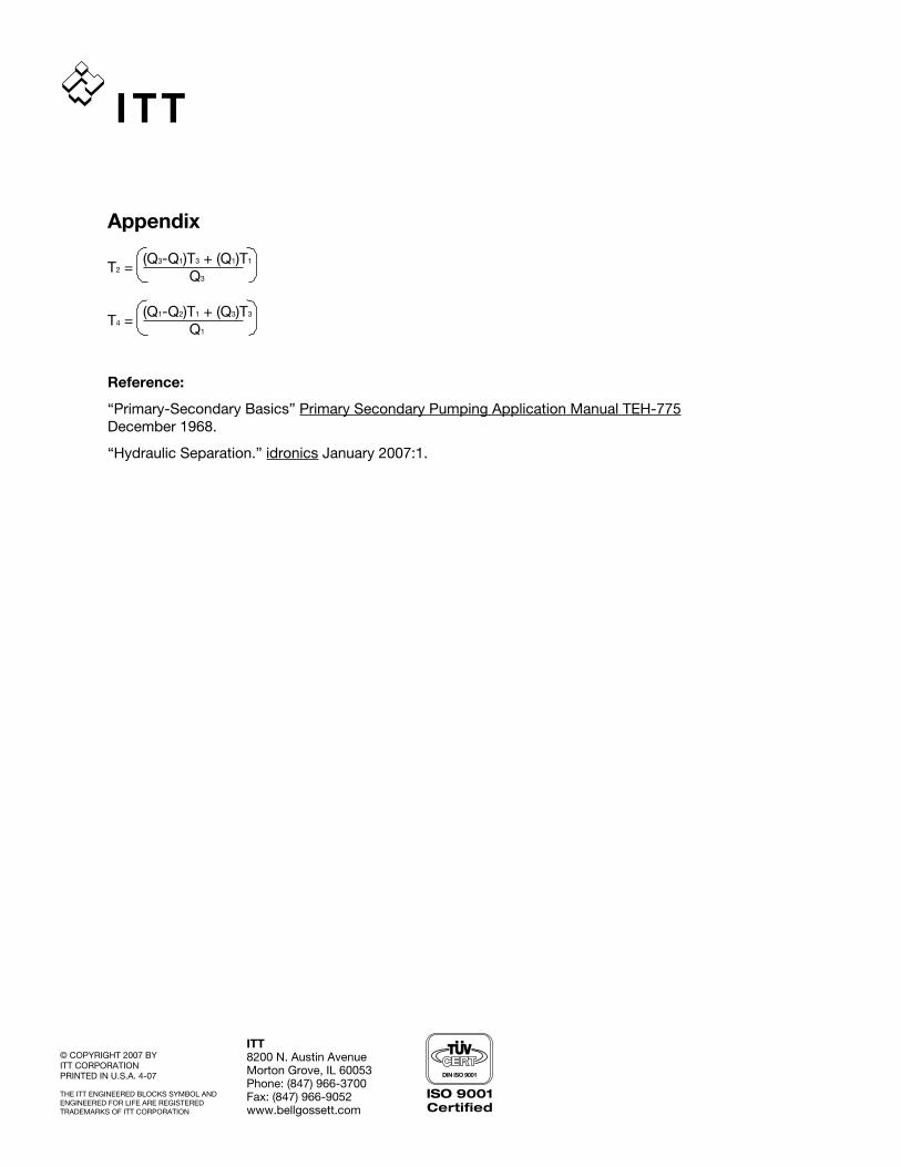
Appendix
T2 =(Q3-Q1)T3 + (Q1)T1
Q3
T4 =(Q1-Q2)T1 + (Q3)T3
Q1
Reference:
“Primary-Secondary Basics” Primary Secondary Pumping Application Manual TEH-775December 1968.
“Hydraulic Separation.” idronics January 2007:1.
SUBMITTAL
A-331 JOB: REPRESENTATIVE: UNIT TAG: ORDER NO. DATE: ENGINEER: SUBMITTED BY: DATE: CONTRACTOR: APPROVED BY: DATE:
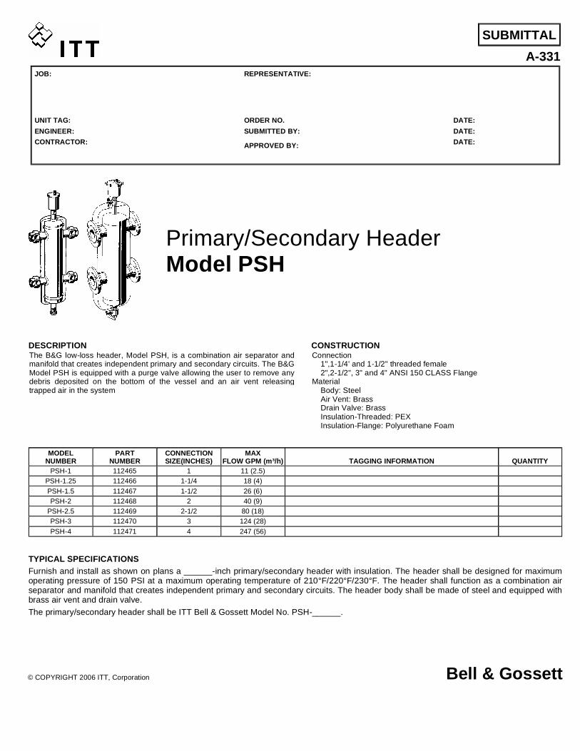
Primary/Secondary Header Model PSH
DESCRIPTION The B&G low-loss header, Model PSH, is a combination air separator and manifold that creates independent primary and secondary circuits. The B&G Model PSH is equipped with a purge valve allowing the user to remove any debris deposited on the bottom of the vessel and an air vent releasing trapped air in the system
CONSTRUCTION Connection 1",1-1/4' and 1-1/2" threaded female 2",2-1/2", 3" and 4" ANSI 150 CLASS Flange Material Body: Steel Air Vent: Brass Drain Valve: Brass Insulation-Threaded: PEX Insulation-Flange: Polyurethane Foam
MODEL NUMBER
PART NUMBER
CONNECTION SIZE(INCHES)
MAX FLOW GPM (m³/h) TAGGING INFORMATION QUANTITY
PSH-1 112465 1 11 (2.5) PSH-1.25 112466 1-1/4 18 (4) PSH-1.5 112467 1-1/2 26 (6) PSH-2 112468 2 40 (9)
PSH-2.5 112469 2-1/2 80 (18) PSH-3 112470 3 124 (28) PSH-4 112471 4 247 (56)
TYPICAL SPECIFICATIONS Furnish and install as shown on plans a ______-inch primary/secondary header with insulation. The header shall be designed for maximum operating pressure of 150 PSI at a maximum operating temperature of 210°F/220°F/230°F. The header shall function as a combination air separator and manifold that creates independent primary and secondary circuits. The header body shall be made of steel and equipped with brass air vent and drain valve. The primary/secondary header shall be ITT Bell & Gossett Model No. PSH-______.
© COPYRIGHT 2006 ITT, Corporation Bell & Gossett
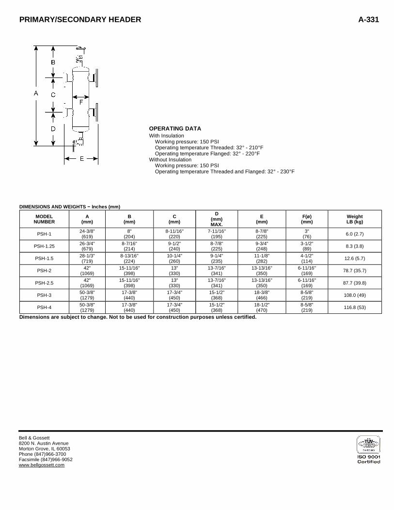
PRIMARY/SECONDARY HEADER A-331
OPERATING DATA With Insulation Working pressure: 150 PSI Operating temperature Threaded: 32° - 210°F Operating temperature Flanged: 32° - 220°F Without Insulation Working pressure: 150 PSI Operating temperature Threaded and Flanged: 32° - 230°F
DIMENSIONS AND WEIGHTS − Inches (mm) MODEL
NUMBERA
(mm)B
(mm)C
(mm)D
(mm) MAX.
E (mm)
F(ø) (mm)
Weight LB (kg)
PSH-1 24-3/8" (619)
8" (204)
8-11/16" (220)
7-11/16" (195)
8-7/8" (225)
3" (76) 6.0 (2.7)
PSH-1.25 26-3/4" (679)
8-7/16" (214)
9-1/2" (240)
8-7/8" (225)
9-3/4" (248)
3-1/2" (89) 8.3 (3.8)
PSH-1.5 28-1/3" (719)
8-13/16" (224)
10-1/4" (260)
9-1/4" (235)
11-1/8" (282)
4-1/2" (114) 12.6 (5.7)
PSH-2 42" (1069)
15-11/16" (398)
13" (330)
13-7/16" (341)
13-13/16" (350)
6-11/16" (169) 78.7 (35.7)
PSH-2.5 42" (1069)
15-11/16" (398)
13" (330)
13-7/16" (341)
13-13/16" (350)
6-11/16" (169) 87.7 (39.8)
PSH-3 50-3/8" (1279)
17-3/8" (440)
17-3/4" (450)
15-1/2" (368)
18-3/8" (466)
8-5/8" (219) 108.0 (49)
PSH-4 50-3/8" (1279)
17-3/8" (440)
17-3/4" (450)
15-1/2" (368)
18-1/2" (470)
8-5/8" (219) 116.8 (53)
Dimensions are subject to change. Not to be used for construction purposes unless certified.
Bell & Gossett 8200 N. Austin Avenue Morton Grove, IL 60053 Phone (847)966-3700 Facsimile (847)966-9052 www.bellgossett.com
TECHNICAL SPECIFICATIONSThreaded Connections: 1", 1-1/4", 1-1/2" FNPT with UnionsFlanged Connections: 2", 2-1/2", 3" & 4" ANSI150 CLASSMaterials: Body: Steel
Air Vent: BrassDrain Valve: BrassInsulation – Threaded: PEXInsulation – Flanged: Polyurethane Foam
Medium: water, glycol solution non-hazardous, thereforeexcluded from the guidelines of 67/548/EC Directive
Maximum Percentage of Glycol: 30% Threaded50% Flanged
INSTALLATION INSTRUCTIONS
The hydraulic separator is installed between the primary andsecondary circuits, always in a vertical position.
Make sure that all connections are water-tight.
When making the water connections, take care not to over-tighten the connections to the reducer. Failure to follow theseinstructions could result in property damage and/or personalinjury.
During the installation, commissioning and maintenance ofhydraulic separators, all necessary steps should be taken to en-sure that system water temperature does not cause danger topeople.
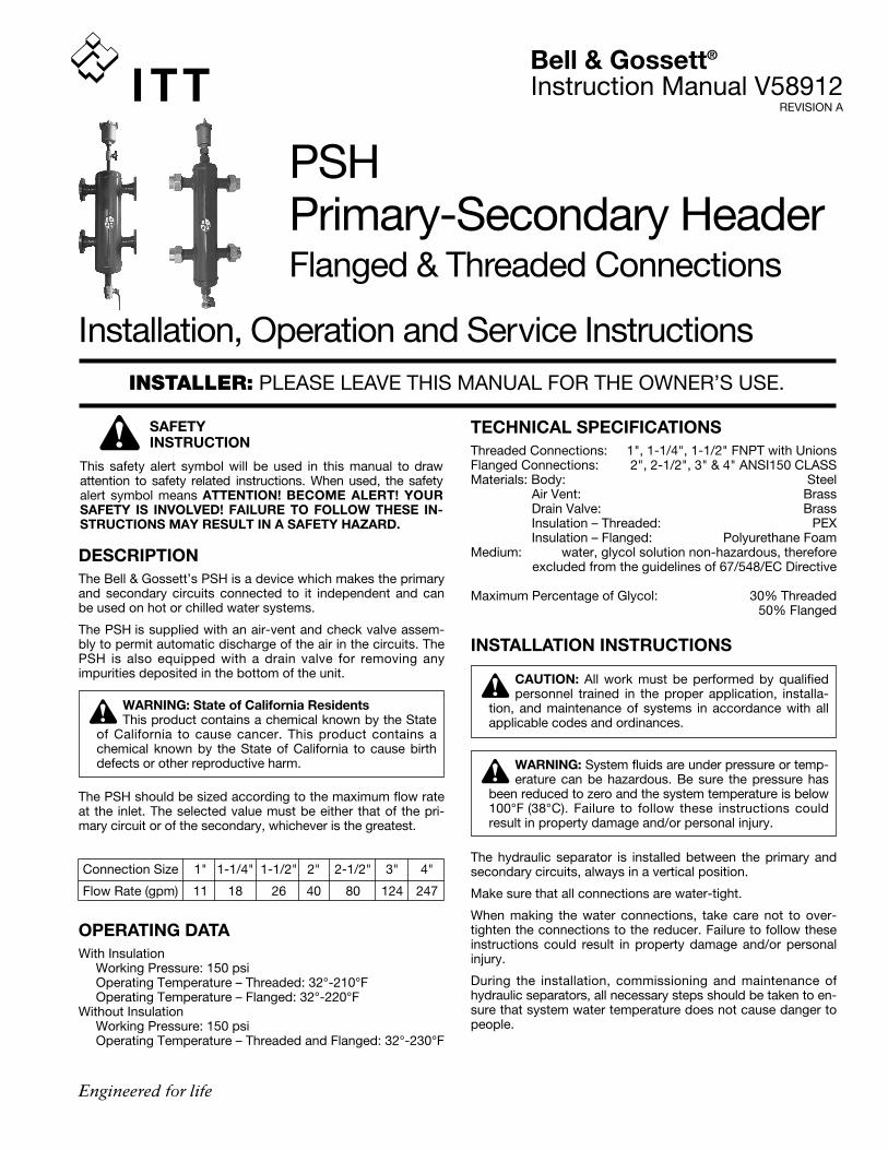
DESCRIPTIONThe Bell & Gossett’s PSH is a device which makes the primaryand secondary circuits connected to it independent and canbe used on hot or chilled water systems.
The PSH is supplied with an air-vent and check valve assem-bly to permit automatic discharge of the air in the circuits. ThePSH is also equipped with a drain valve for removing anyimpurities deposited in the bottom of the unit.
The PSH should be sized according to the maximum flow rateat the inlet. The selected value must be either that of the pri-mary circuit or of the secondary, whichever is the greatest.
Connection Size 1" 1-1/4" 1-1/2" 2" 2-1/2" 3" 4"
Flow Rate (gpm) 11 18 26 40 80 124 247
OPERATING DATAWith Insulation
Working Pressure: 150 psiOperating Temperature – Threaded: 32°-210°FOperating Temperature – Flanged: 32°-220°F
Without InsulationWorking Pressure: 150 psiOperating Temperature – Threaded and Flanged: 32°-230°F
Installation, Operation and Service Instructions
PSHPrimary-Secondary HeaderFlanged & Threaded Connections
SAFETY INSTRUCTION
This safety alert symbol will be used in this manual to drawattention to safety related instructions. When used, the safetyalert symbol means ATTENTION! BECOME ALERT! YOURSAFETY IS INVOLVED! FAILURE TO FOLLOW THESE IN-STRUCTIONS MAY RESULT IN A SAFETY HAZARD.
INSTALLER: PLEASE LEAVE THIS MANUAL FOR THE OWNER’S USE.
Bell & Gossett®
Instruction Manual V58912REVISION A
CAUTION: All work must be performed by qualifiedpersonnel trained in the proper application, installa-
tion, and maintenance of systems in accordance with allapplicable codes and ordinances.
WARNING: State of California ResidentsThis product contains a chemical known by the State
of California to cause cancer. This product contains achemical known by the State of California to cause birthdefects or other reproductive harm. WARNING: System fluids are under pressure or temp-
erature can be hazardous. Be sure the pressure hasbeen reduced to zero and the system temperature is below100°F (38°C). Failure to follow these instructions couldresult in property damage and/or personal injury.
5. Reassemble the two side sections, fitting the lower capinto one of the two sections and then connecting the other.
6. Finish the assembly with the adhesive tape provided in thebox.
7. Complete with the two black head covers.
8. Fit the automatic air vent and the drain valve.
Recommended sealant: Superclear mastic.
SERVICE INSTRUCTIONSThere is no service required for the PSH.
CAUTION: Corrosion or leakage of the PSH can causedamage or injury. Periodically inspect the PSH for
signs of leakage or corrosion. If noted, PSH must bereplaced. Failure to follow these instructions could result inproperty damage and/or moderate personal injury.
Procedure for installation and insulationassembly on threaded models
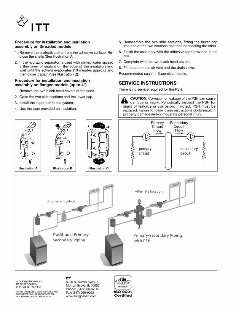
1. Remove the protective strip from the adhesive surface. Re-close the shells (See Illustration A).
2. If the hydraulic separator is used with chilled water spreada thin layer of sealant on the edge of the insulation andwait until the solvent evaporates (10 minutes approx.) andthen close it again (See Illustration B).
Procedure for installation and insulationassembly on flanged models (up to 4")
1. Remove the two black head covers at the ends.
2. Open the two side sections and the lower cap.
3. Install the separator in the system.
4. Use the tape provided on insulation.
Illustration A Illustration B Illustration C
secondarycircuit
primarycircuit
PrimaryCircuitFlow
SecondaryCircuitFlow
ITT8200 N. Austin AvenueMorton Grove, IL 60053Phone: (847) 966-3700Fax: (847) 966-9052www.bellgossett.com
© COPYRIGHT 2007 BY ITT CORPORATIONPRINTED IN ITALY 4-07
THE ITT ENGINEERED BLOCKS SYMBOL ANDENGINEERED FOR LIFE ARE REGISTEREDTRADEMARKS OF ITT CORPORATION