Embed Size (px)
Citation preview
TITLE
Image
1
PAM4 signals for 400 Gbps: acquisition for measurement and signal processing
V1.00
Marlett, Wang, Weem, Zivny: PAM4 for 400G2
Introduction, content
High speed serial data links are in the process in increasing line speeds from 25 Gb/s to 50 Gb/s and higher. This is being implemented largely by moving from PAM2 NRZ signaling to PAM4 NRZ signaling. We consider the following aspects of measurement methodology addressing this change:
1. Measurement bandwidth considerations for measurement of performance and of compliance of PAM4 transmitters
2. Impact of PAM4 clock recovery system on measurement 3. Receiver equalization methodology for measurements on
equalized PAM4 links
Marlett, Wang, Weem, Zivny: PAM4 for 400G3
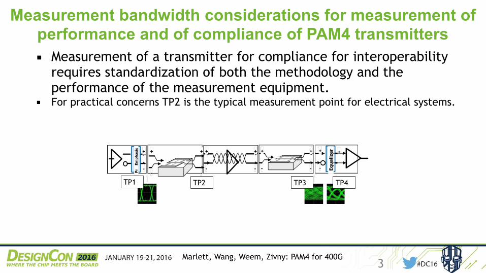
Measurement bandwidth considerations for measurement of performance and of compliance of PAM4 transmitters▪ Measurement of a transmitter for compliance for interoperability
requires standardization of both the methodology and the performance of the measurement equipment.
▪ For practical concerns TP2 is the typical measurement point for electrical systems.
TP2
TP3
TP4
TP1
Marlett, Wang, Weem, Zivny: PAM4 for 400G4
Bandwidth requirements for testing of PAM4 signal: 4x25G electrical: “Ideal” PAM4 Tx, unlim BW Scope
DC16 PAM4 signals for 400G…
Marlett, Wang, Weem, Zivny Page 6 of 18 2016_01
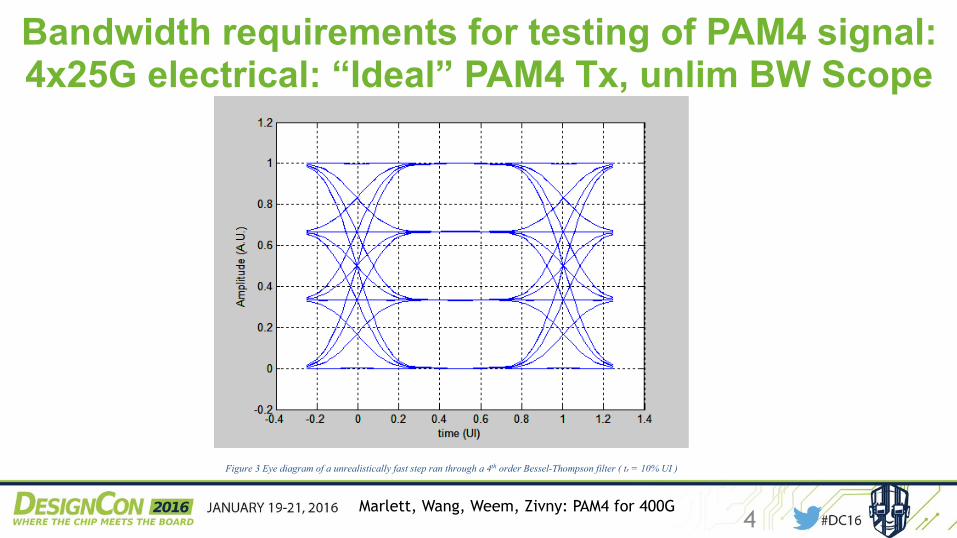
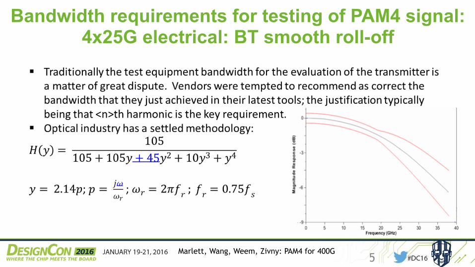
‐ The ‐3 dB power is relative low, at ‐3 dB at symbol rate. ‐ There is no sharp roll‐off; the frequency response rolls off smoothly in a nearly
Gaussian filter fashion to 1.5x bit‐rate.
The above provides two features: the measurement happens in a frequency span that is not much wider than that of the receiver; so the measuring system doesn’t acquire signal artifacts and noise that is not of concern since it’s out of band of the receiver… And the time‐domain aberrations are minimal, since the B‐T filter is very clean in time domain. This is shown in a simulated PAM4 eye diagram below.
Figure 3 Eye diagram of a unrealistically fast step ran through a 4th order Bessel-Thompson filter ( tr = 10% UI )
2.3. Bandwidth requirements for testing of PAM4 signal:
100G PAM2 Electrical precedent The 100Gx4 PAM2 NRZ electrical world (25.78125 Gb/s signaling) adopted the requirement of a reference receiver outlined in the optical systems above. This is again a Bessel-Thompson filter of the 4th order. The bandwidth of this receiver is specified as fs = 33 GHz for the 25.781 Gb/s standard bit-rate of the standard.
Marlett, Wang, Weem, Zivny: PAM4 for 400G5
Bandwidth requirements for testing of PAM4 signal: 4x25G electrical: BT smooth roll-off
Marlett, Wang, Weem, Zivny: PAM4 for 400G6
Moving from PAM2 NRZ to PAM4 NRZ: electrical: smooth roll-off… at what frequency?
▪ 100G PAM2 Electrical precedent is 33 GHz for 25.78125 Gb/s This is not necessarily the best choice but it appears to be a good enough for PAM2. ▪ What does that say for PAM4 ? ▪ Postulate: if PAM2 has certain eye closure, and this worked
out for the industry, then similar eye closure will work out at PAM4 as well.
Marlett, Wang, Weem, Zivny: PAM4 for 400G7
Vertical Eye Closure (due to measurement tool) as a measure of measurement fidelity
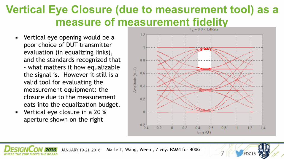
▪ Vertical eye opening would be a poor choice of DUT transmitter evaluation (in equalizing links), and the standards recognized that - what matters it how equalizable the signal is. However it still is a valid tool for evaluating the measurement equipment: the closure due to the measurement eats into the equalization budget.
▪ Vertical eye closure in a 20 % aperture shown on the right
Marlett, Wang, Weem, Zivny: PAM4 for 400G8
Closure of which eye
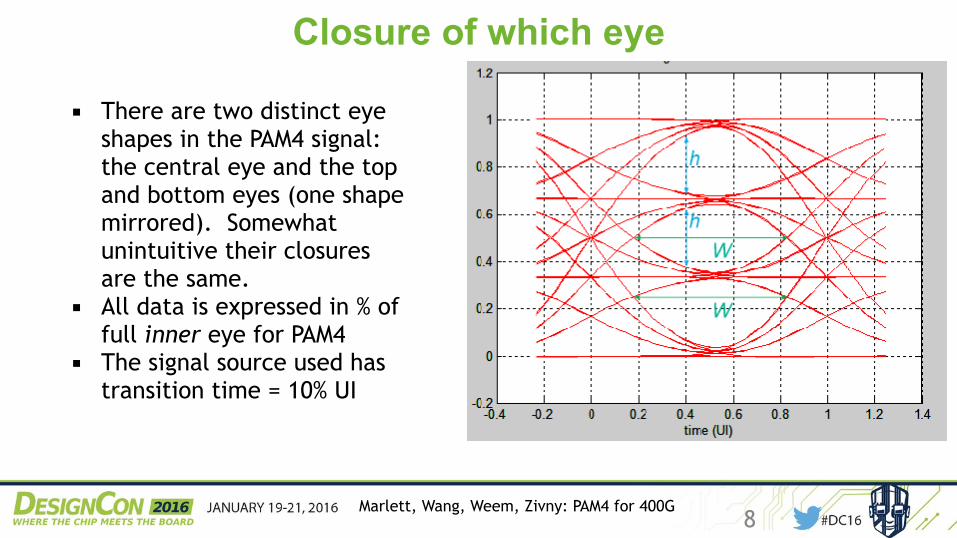
▪ There are two distinct eye shapes in the PAM4 signal: the central eye and the top and bottom eyes (one shape mirrored). Somewhat unintuitive their closures are the same.
▪ All data is expressed in % of full inner eye for PAM4
▪ The signal source used has transition time = 10% UI
Marlett, Wang, Weem, Zivny: PAM4 for 400G9
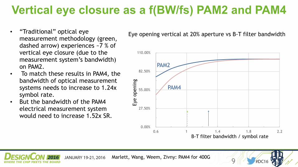
Vertical eye closure as a f(BW/fs) PAM2 and PAM4• “Traditional” optical eye
measurement methodology (green, dashed arrow) experiences ~7 % of vertical eye closure (due to the measurement system’s bandwidth) on PAM2.
• To match these results in PAM4, the bandwidth of optical measurement systems needs to increase to 1.24x symbol rate.
• But the bandwidth of the PAM4 electrical measurement system would need to increase 1.52x SR.
0.00%
27.50%
55.00%
82.50%
110.00%
0.6 1 1.4 1.8 2.2
Eye opening vertical at 20% aperture vs B-T filter bandwidth
PAM2
B-T filter bandwidth / symbol rateEy
e op
enin
g
PAM4
Marlett, Wang, Weem, Zivny: PAM4 for 400G10
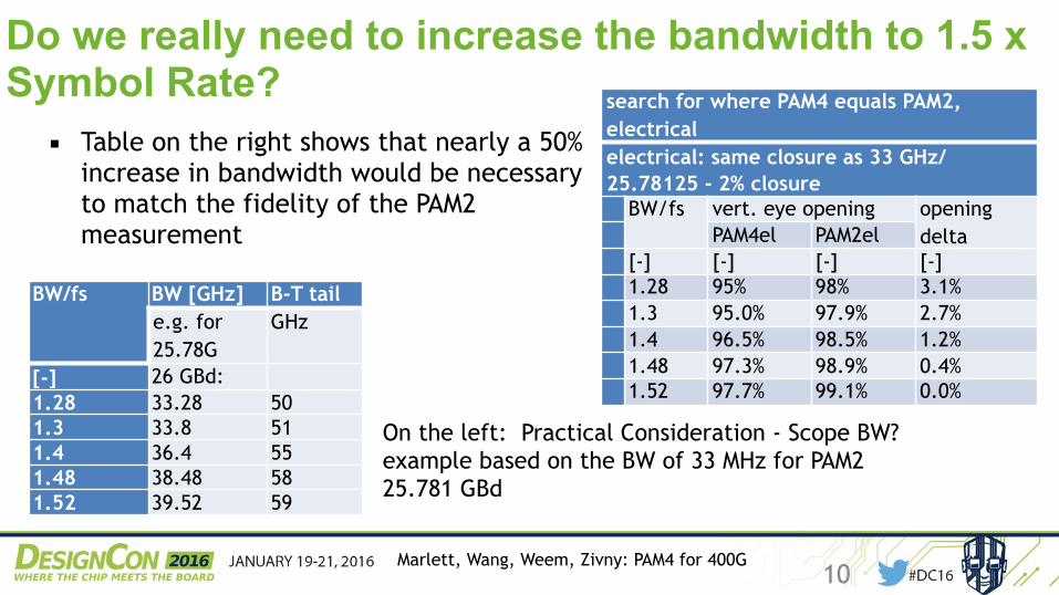
Do we really need to increase the bandwidth to 1.5 x Symbol Rate?
▪ Table on the right shows that nearly a 50% increase in bandwidth would be necessary to match the fidelity of the PAM2 measurement
search for where PAM4 equals PAM2, electricalelectrical: same closure as 33 GHz/25.78125 - 2% closure
BW/fs vert. eye opening opening deltaPAM4el PAM2el
[-] [-] [-] [-]1.28 95% 98% 3.1%1.3 95.0% 97.9% 2.7%1.4 96.5% 98.5% 1.2%1.48 97.3% 98.9% 0.4%1.52 97.7% 99.1% 0.0%
BW/fs BW [GHz] B-T taile.g. for 25.78G
GHz
[-] 26 GBd: 1.28 33.28 501.3 33.8 511.4 36.4 551.48 38.48 581.52 39.52 59
On the left: Practical Consideration - Scope BW?example based on the BW of 33 MHz for PAM2 25.781 GBd
Marlett, Wang, Weem, Zivny: PAM4 for 400G11
Recommendations for measurement bandwidth for PAM4
▪ For electrical measurements, moving from PAM2 to PAM4 increase the bandwidth only slightly…. so recommendation is… 1.3 times the symbol rate. At 5% the vertical closure (PAM4) is larger than that experienced today for PAM2 (which is 2% with 33 GHz measurement on 25.781 GBd) but still smaller than in optical systems today (optical eye closure is about 7%).
▪ For optical systems keep the vertical error in check by increasing the bandwidth to 1.24 times the symbol rate (for closure increase from ~ 6% to ~ 7%)
▪ PAM4 Bandwidth - BT roll off to 1.5* BW. Not an easy task, especially for 53 GBd.
Marlett, Wang, Weem, Zivny: PAM4 for 400G12
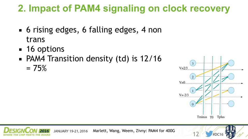
2. Impact of PAM4 signaling on clock recovery
▪ 6 rising edges, 6 falling edges, 4 non trans
▪ 16 options ▪ PAM4 Transition density (td) is 12/16
= 75%
Marlett, Wang, Weem, Zivny: PAM4 for 400G13
Possible PAM4 phase detectors
▪ Simplest: 1 detector: 0V crossing; allow all edges that cross to be counted
▪ More complicated: 1 detector: 0V crossing; Restrict data to symmetric data, i.e. 03--30 or 12--21 transitions
▪ Even more complicated: 3 detectors: -2/3, 0, 2/3 ▪ Full detect: 5 detectors: -2/3, -1/3, 0, 1/3, 2/3
Marlett, Wang, Weem, Zivny: PAM4 for 400G14
Receiver technology
▪ DSP CDR receiver: use voltage samples (1UI time spaced). Can use all transitions as information and essentially ignores edge timing, and require processing time for CDR updates, so the PLL Loop bandwidth is sub-MHz.
▪ On the other hand an analog receiver can evaluate edge timing and allows 10 MHz PLL loop… but it is difficult to evaluate multiple thresholds/transitions.
Marlett, Wang, Weem, Zivny: PAM4 for 400G15
Technology directly impacts the measurement
▪ Since the PLL loop bandwidth (and jitter tracking, etc.) is so severely impacted by the technology used in the receiver ( DSP vs analog loop), an explicit requirement has to be made in the standard whether support one, the other, or most likely both
Marlett, Wang, Weem, Zivny: PAM4 for 400G16
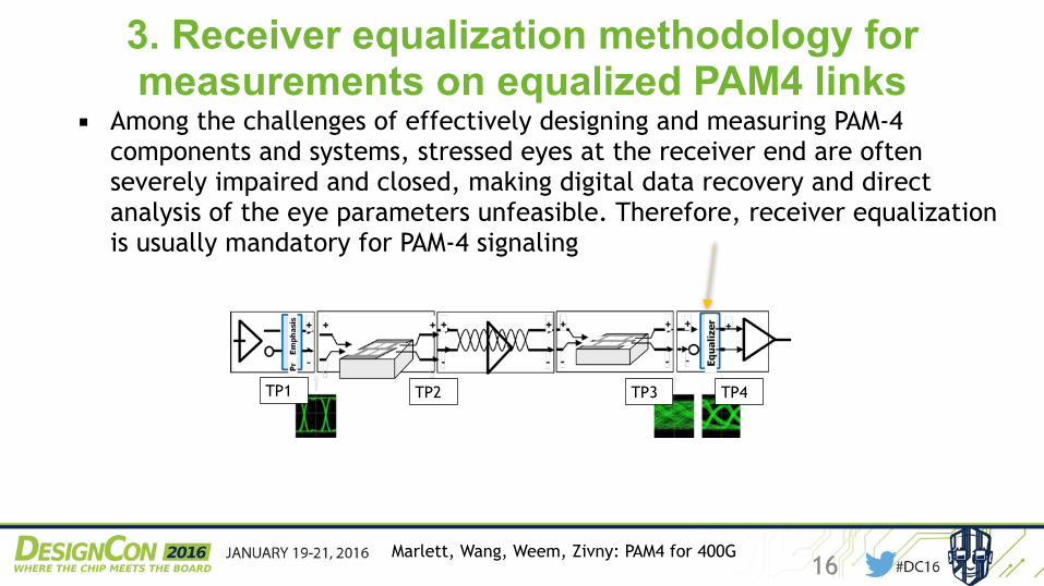
3. Receiver equalization methodology for measurements on equalized PAM4 links
▪ Among the challenges of effectively designing and measuring PAM-4 components and systems, stressed eyes at the receiver end are often severely impaired and closed, making digital data recovery and direct analysis of the eye parameters unfeasible. Therefore, receiver equalization is usually mandatory for PAM-4 signaling
TP2
TP3
TP4
TP1
Marlett, Wang, Weem, Zivny: PAM4 for 400G17
Bandwidth requirements in links and receiver equalization
▪ A question with regard to the test of equalizing links is this: does the presence of the equalizer in the receiver relax the requirement on the performance of the test equipment?
▪ i.e., if the receiver is equalizing, does that mean that the measurement on the transmitter doesn’t have to be performed with high bandwidth?
▪ Our answer to this question is “no” – the transmitter performance needs to be evaluated for impact on possibly unusual equalization on possibly very short links. Understanding what the transmitter really is doing remains the key to interoperability.
Marlett, Wang, Weem, Zivny: PAM4 for 400G18
Equalizing setup for PAM4
Today’s PAM4 systems use the same setup as PAM2 systems ▪ Linear equalizer: Continuous time linear equalizer
(CTLE), feed forward equalizer (FFE) ▪ Nonlinear equalizer: Decision feedback equalizer (DFE) With some of the linear equalization possibly present in the transmitter. In principle, established NRZ linear equalizer methodologies still apply for PAM-4 …
Marlett, Wang, Weem, Zivny: PAM4 for 400G19
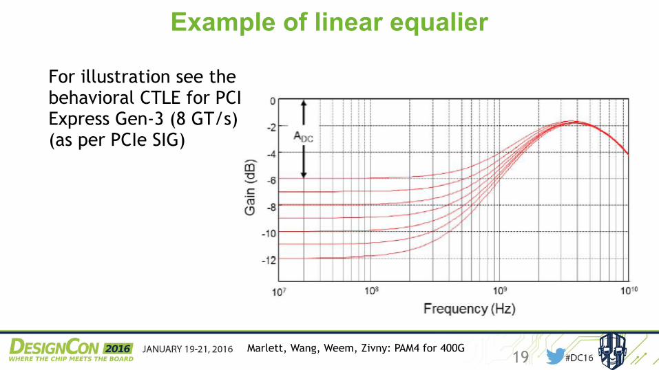
Example of linear equalier
For illustration see the behavioral CTLE for PCI Express Gen-3 (8 GT/s) (as per PCIe SIG)
Marlett, Wang, Weem, Zivny: PAM4 for 400G20
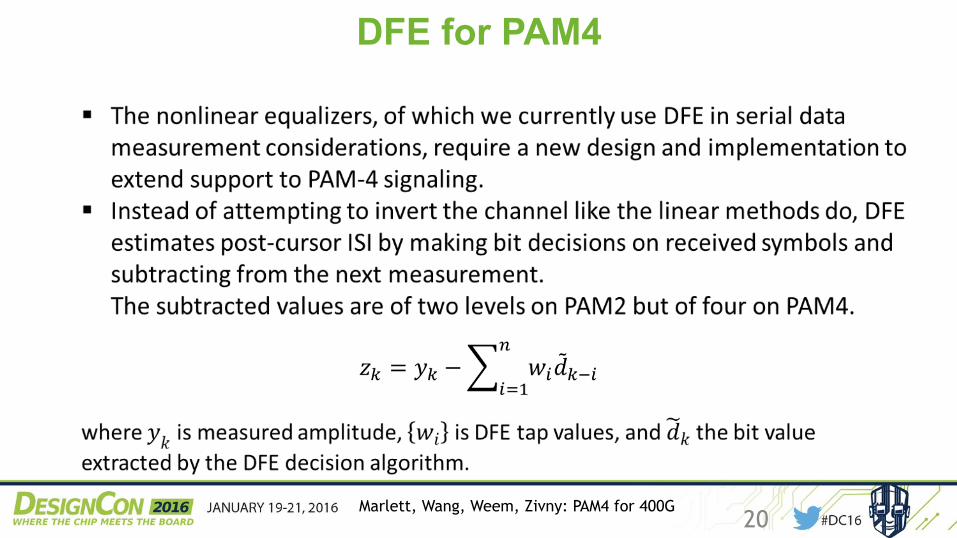
DFE for PAM4
Marlett, Wang, Weem, Zivny: PAM4 for 400G21
DFE for PAM4
▪ In the end the PAM-4 aware DFE algorithm enables ISI removal without noise amplification just as it does in PAM2, so contributing to the interpretation and assessment of PAM-4 signals with complex transition and leveling schemes.
▪ Furthermore, to compensate for changing ISI, DFE parameters are often adaptively determined based on the newest incoming data stream. In our PAM-4 DFE design, a least-square optimization was performed to determine the optimal DFE tap values.
Marlett, Wang, Weem, Zivny: PAM4 for 400G22
Example of an equalized PAM4 signal
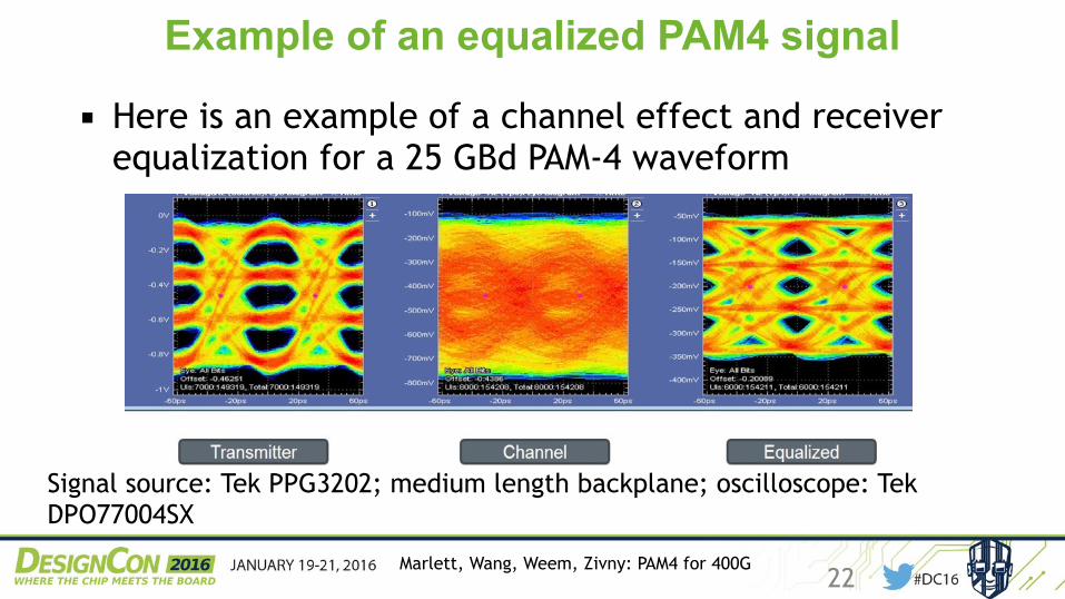
▪ Here is an example of a channel effect and receiver equalization for a 25 GBd PAM-4 waveform
Signal source: Tek PPG3202; medium length backplane; oscilloscope: Tek DPO77004SX
Marlett, Wang, Weem, Zivny: PAM4 for 400G23
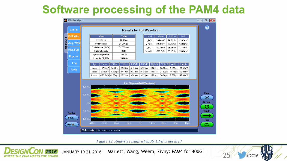
Software processing of the PAM4 data
▪ Post-capture, the waveform was clock-recovered in SW and equalization was performed in SW.
Note: SW clock recovery on PAM4 easily supports the super-set of the likely PAM4 clock recovery methodologies. This includes the set-ability of PLL Loop BW to either DSP-like or to analog-like frequency.
Signal analysis and clock recovery: Tek DPOJET software package. Equalization, channel emulation: Tek SDLA software package.
Marlett, Wang, Weem, Zivny: PAM4 for 400G24
Software processing of the PAM4 data DC16 PAM4 signals for 400G…
Marlett, Wang, Weem, Zivny Page 16 of 18 2016_01
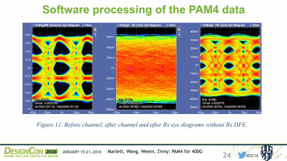
Figure 11. Before channel, after channel and after Rx eye diagrams without Rx DFE.
Figure 12. Analysis results when Rx DFE is not used.
Marlett, Wang, Weem, Zivny: PAM4 for 400G25
Software processing of the PAM4 data
DC16 PAM4 signals for 400G…
Marlett, Wang, Weem, Zivny Page 16 of 18 2016_01
Figure 11. Before channel, after channel and after Rx eye diagrams without Rx DFE.
Figure 12. Analysis results when Rx DFE is not used.
Marlett, Wang, Weem, Zivny: PAM4 for 400G26
Software processing of the PAM4 data DC16 PAM4 signals for 400G…
Marlett, Wang, Weem, Zivny Page 17 of 18 2016_01
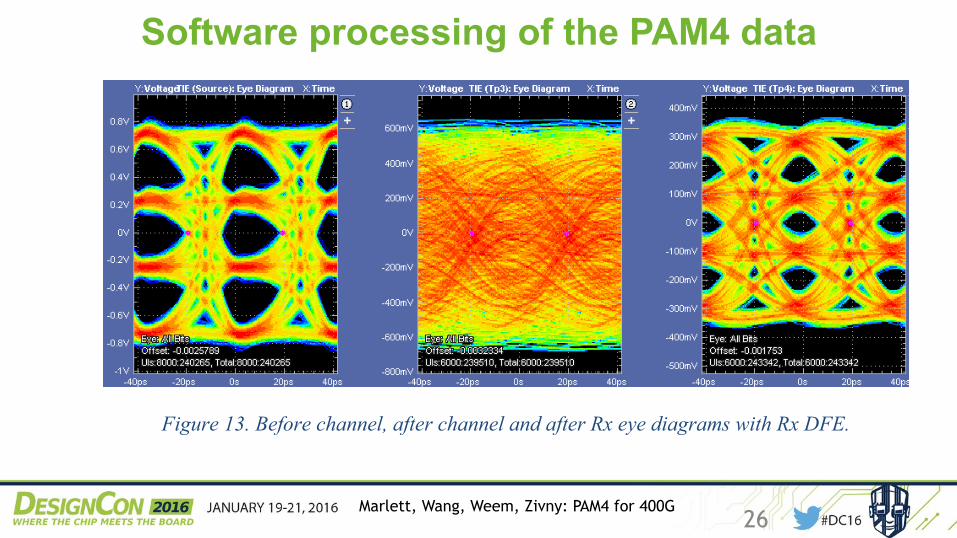
Figure 13. Before channel, after channel and after Rx eye diagrams with Rx DFE.
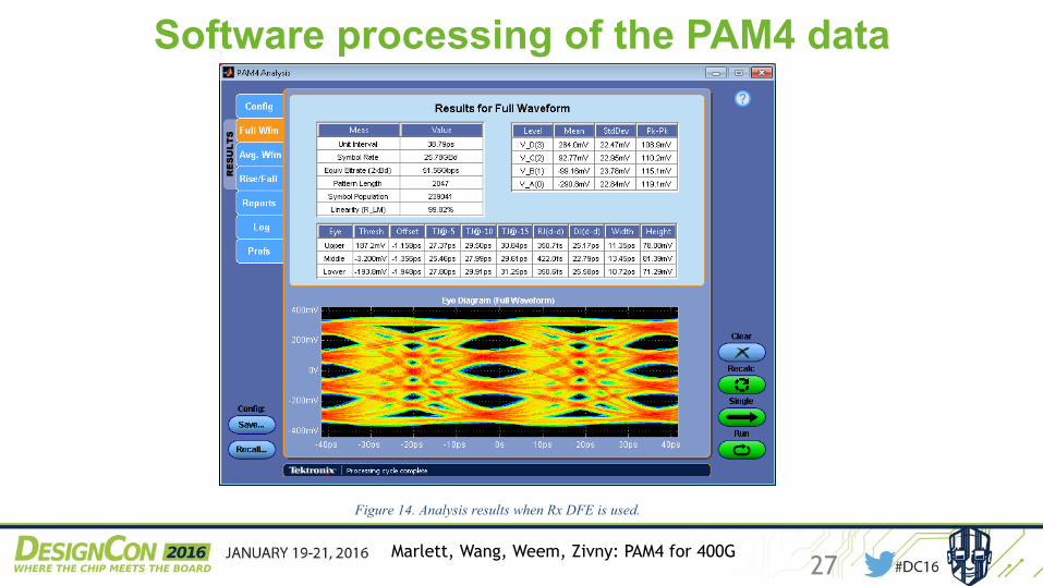
Figure 14. Analysis results when Rx DFE is used.
Table 3 illustrates the impact of DFE on opening eye diagram and enabling subsequent analysis. For this investigation a 16-tap DFE was used.
Marlett, Wang, Weem, Zivny: PAM4 for 400G27
Software processing of the PAM4 data
DC16 PAM4 signals for 400G…
Marlett, Wang, Weem, Zivny Page 17 of 18 2016_01
Figure 13. Before channel, after channel and after Rx eye diagrams with Rx DFE.
Figure 14. Analysis results when Rx DFE is used.
Table 3 illustrates the impact of DFE on opening eye diagram and enabling subsequent analysis. For this investigation a 16-tap DFE was used.
Marlett, Wang, Weem, Zivny: PAM4 for 400G28
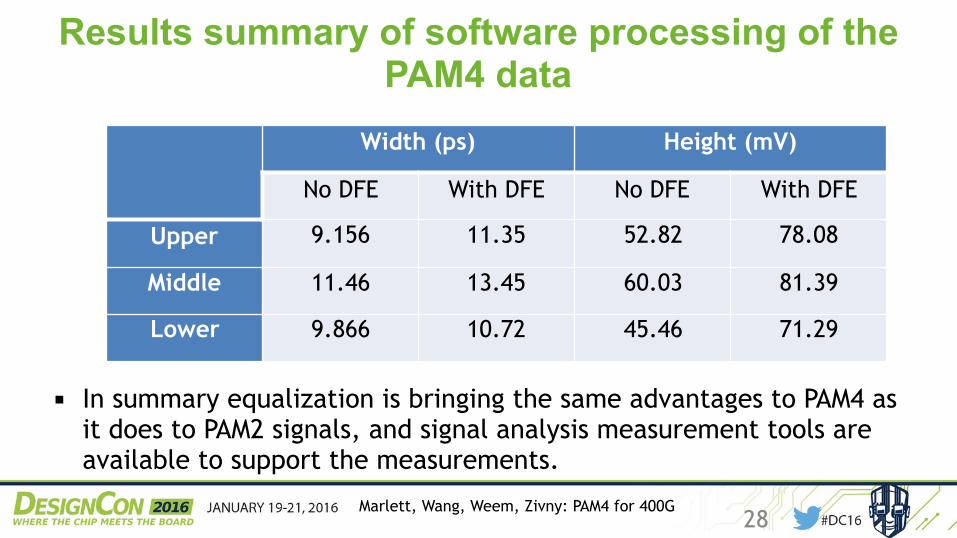
Results summary of software processing of the PAM4 data
▪ In summary equalization is bringing the same advantages to PAM4 as it does to PAM2 signals, and signal analysis measurement tools are available to support the measurements.
Width (ps) Height (mV)
No DFE With DFE No DFE With DFE
Upper 9.156 11.35 52.82 78.08
Middle 11.46 13.45 60.03 81.39
Lower 9.866 10.72 45.46 71.29
Marlett, Wang, Weem, Zivny: PAM4 for 400G29
Conclusions
▪ We considered the impact of measurement tools’ bandwidth on the fidelity of
measurement of PAM4 signal; we’ve compared this to PAM2, and we recommend
bandwidth for electrical measurement on PAM4.
▪ We presented an overview of the features of PAM4 signal on clock recovery
methodology: the measurement jitter tracking is dependent on the technology of the
receiver.
▪ And finally we’ve presented an example of equalization of PAM4 signal – acquired live
signal – in the oscilloscope toolset, and demonstrated that the equalization
methodology used in PAM2 is a good toolset for measurement equalization in PAM4.
Marlett, Wang, Weem, Zivny: PAM4 for 400G30
QUESTIONS?
Thank you!
John Smith, Applications Engineer, [email protected]


![CHAPTER-4 Line Codes RZ: Return to Zero [ pulse for half ... · NRZ . Return to Zero[ pulse for full duration of T. b ] Unipolar (NRZ) Unipolar NRZ . NRZ-inverted (differential](https://img.pdfslide.net/doc/110x75/5cc1fa9b88c9933e3a8d2cb0/chapter-4-line-codes-rz-return-to-zero-pulse-for-half-nrz-return-to.jpg)