Embed Size (px)
Citation preview
PSync: Visible Light-Based Time Synchronizationfor Internet of Things (IoT)
XiangFa Guo∗, Mobashir Mohammad∗, Sudipta Saha∗, Mun Choon Chan∗, Seth Gilbert∗, Derek Leong†∗School of Computing, National University of Singapore, Singapore
†Institute for Infocomm Research, Singapore{xiangfa, mobashir, sudipta, chanmc, seth.gilbert}@comp.nus.edu.sg, [email protected]
Abstract—Time synchronization is an enabling service thatallows devices to share a consistent notion of time and thusmakes it easier to build efficient and robust collaborative services.However, existing synchronization protocols based on wirelesspacket transmissions are not energy efficient because poweringthe radio often consumes a significant fraction of the energybudget. In this paper, we propose PSync, a visible light-basedtime synchronization protocol that relies on an LED light sourceand is highly energy efficient for the receivers. The key noveltyin our protocol is the use of a De Bruijn sequence to provide arough estimate of time using a minimum amount of information.Experiments show that our scheme achieves an average synchro-nization error of 1.3 timer ticks (32 µs per clock tick). In addition,the additional energy consumed for one round of synchronizationbased on PSync can be as low as 19% of the energy needed toreceive a small packet (1 byte) using IEEE 802.15.4 radio.
I. INTRODUCTION
With the emergence of the Internet of Things (IoT), de-signing highly energy-efficient protocols suitable for use ina localized or indoor environment such as inside a room orvehicle becomes interesting. In many of these usage scenarios,while the end devices may be highly resource constrained, aresource-rich device may be nearby.
In this paper, we focus on the problem of synchronizingresource-constrained IoT devices. Time synchronization is akey enabling service when there is a need for many devices tocoordinate their actions. By ensuring that all the devices sharea consistent notion of time, it becomes much easier to buildefficient and robust collaborative services.
Typically, synchronization protocols for these wireless net-works rely on the fact that every wireless device receives agiven packet at (approximately) the same instance of time.Thus, if some device sends a synchronization packet, otherdevices that receive the packet can synchronize on the instantof packet reception. The energy consumed by these synchro-nization protocols depends on the cost of radio transmissionand reception. For resource-constrained devices, powering theradio can consume a significant fraction of the energy budget.Further, in order to execute the synchronization protocol viapacket reception, devices often need to keep the radio on for
This work was supported in part by the Agency for Science, Technologyand Research (A*STAR), Singapore, under SERC Grant 1224104049.
a period much longer than the actual packet transmission andreception duration, leading to higher energy consumption.
In this paper, we propose PSync, a visible light-based timesynchronization protocol. The main idea in our design is thatpulses of light produced by light emitting diodes (LEDs) yielda very efficient mechanism for synchronizing nearby devices.
PSync utilizes an asymmetric design and is motivated by thewidespread deployment of LEDs. The use of LEDs is expectedto grow due to its energy efficiency [1]. These ambient LEDlight sources have very fast (nanosecond) switching times andare highly programmable. The power efficiency in the receiverarises from the following factors. First, the photodetectors(PDs) or light sensors in the receivers consume very littlepower. Second, the sampling of light sensors can be done ata high rate. Therefore, it is possible for a device (receiver) tosleep most of the time and only wake up over short intervalsto perform synchronization. In order to synchronize, one ormore light sources (simultaneously) broadcast a predeterminedbit sequence (where ON is 1 and OFF is 0) and devicessynchronize on the transition of a specific pulse.
The key challenge of PSync is the design of the bitsequence. In order to be highly energy efficient, a receivershould be awake only for a very short interval and yet be ableto quickly determine the synchronization point. In our design,a receiver first performs low-frequency sampling to estimatethe approximate time to the actual synchronization point andsubsequently wakes up to perform high-frequency samplingjust before the synchronization point.
Our solution to designing the bit sequence is to use aDe Bruijn sequence [2], which has the following specialproperty: each possible sequence of N bits (there are 2N suchsequences) can be found in a unique position within a DeBruijn sequence of 2N bits. Thus, we may determine our po-sition in such a sequence by reading only N consecutive bits.While De Bruijn sequences have been applied in genomics,pattern recognition [3], our application of this technique forsynchronization is novel.
We have fully implemented our synchronization protocolusing an off-the-shelf LED light source controlled by TelosB.Our evaluation shows that PSync can achieve an averagesynchronization error of 1.3 timer ticks (32 µs per clock tick).Using a light pulse width of 1 ms, one synchronization cycleof PSync consumes around 57 µJ. In comparison, the reception

100 200 300 400 500 600 700
50 100 150 200 250
Lux
Time (ms)
100 200 300 400 500 600 700
50 100 150 200 250
Lux
Time (ms)
Fig. 1. Light sensor readings from 2 TelosB motes detecting the same lightsource.
of a small (1 byte) packet over the IEEE 802.15.4 radioconsumes 171 µJ. The energy consumption of PSync can befurther reduced by using a smaller pulse width. With a 0.5 mspulse width, synchronization power consumption reduces to32 µJ.
This paper is organized as follows. In Section II, we presentrelated work. We motivate the possibility and benefit of light-based synchronization in Section III and present the protocoldetails in Sections IV through VI. Experiments are presentedin Section VII, discussions in Section VIII, and we concludein Section IX.
II. RELATED WORK
Visible light based communication (VLC): Visible lightcommunication over a short range has been standardized asIEEE 802.15.7. The standard supports data rates of up to96 Mb/s. Schmid et al. [4] demonstrated a prototype systemfor using low power LEDs that supports low data rate (lessthan 1 Kbps) over a distance of up to 2 m. Visible light has alsobeen used for localization. In Epsilon [5], a receiver employs alight sensor to retrieve the beacon information which includesmeasured RSS (received signal strength) values. The RSSvalues are later used to compute the distances to multiplebulbs.
Time synchronization and calibration: For devices withreliable Internet connections and no resource constraint, timesynchronization is well understood. It can, for example, beprovided by a service such as the network time protocol(NTP) [6]. On resource-constrained wireless networks, a vari-ety of synchronization protocols, such as RBS [7], TPSN [8],FTSP [9], and Glossy [10] have been proposed. These proto-cols use RF communications among the nodes and the timeof packet reception as a reference. Mostly, they can achievefast synchronization and accuracy on the order of 10 µs or less.However, the nodes need to keep their radios always on duringthe synchronization process, which can consume significantenergy.
A related issue is clock calibration. Calibration is used tocompensate for clock drift after synchronization is done and
50
100
150
200
250
300
350
400
450
500
550
600
0 500 1000 1500 2000 2500 3000
Lu
x
Time (us)
Fig. 2. Light intensity detected by a TelosB mote with blinking rate of 5 kHz.
can be used to reduce errors between clock synchronizations,hence reducing the need for more frequent synchronization.The proposed techniques mostly try to use periodic back-ground signals to perform calibration. For example, Li etal. [11] use the periodicity of the pulse from FM radio broad-cast to calibrate the clocks in different nodes. FLIGHT [12]uses the periodic change in the intensity of the light emittedfrom indoor fluorescent lamps to achieve the same. Note thateven after calibration, more work needs to be done to achievesynchronization. In FLIGHT, protocols such as FTSP is stillneeded to provide the initial time reference.
Preamble sampling based MAC protocols: In wirelesssensor networks, MAC protocols that employ preamble sam-pling have been proposed, e.g., B-MAC [13], X-MAC [14],CMAC [15], and other related asynchronous MAC protocols.In these protocols, the preambles either just indicate activi-ties (e.g., channel is busy) or MAC addresses; they are notexplicitly designed for fine-grained synchronization.
Our contribution: Our proposed protocol PSync is novel inthat visible light is used for synchronization rather than com-munication. The technique is based on a De Bruijn sequencewhich enables a receiver to quickly obtain a rough estimateof the synchronization point by reading only a small numberof bits.
III. MOTIVATION AND BASIC MEASUREMENT RESULTS
In order to test the feasibility of visible light-based timesynchronization, we conducted the experiments described be-low.
For a radio-based synchronization protocol [10], the basicassumption is that the SFD pins of the radio fall exactly at thesame time for all the devices on receiving the synchronizationpacket. This provides all the devices a common synchronousevent. For visible light-based time synchronization to befeasible, we need an analogous synchronous event observableby all the devices simultaneously. The rise and fall time foran LED is on the order of nanoseconds [1], and hence, LEDsare ideal candidates — as long as the rise and fall observedby the sensors is sharp.

Preamble
W Aggressive Sampling
S
D1
D2
D3
W
W W Aggressive Sampling
W Aggressive Sampling
Synchronisation Point
Fig. 3. A naive preamble allowing duty cycling devices to accuratelysynchronize at the falling edge.
TABLE INOTATION
Symbol Definition
τ time for transmitting one bit in the preamble2ν length of the De Bruijn sequenceν length of the unique subsequenceκ number of bits for verification
To validate this observation, we deployed two TelosB de-vices and programmed them to sample light at a rate of 1 kHz,with a light source blinking at different rates. From the resultsshown in Fig. 1, we can see that the edges are very sharp andthe devices can clearly detect these rise and fall events with asynchronization error bounded by the sampling rate.
The next question is whether we can easily program thetransmitter to blink at a very high rate and whether the receivercan detect the changes in light intensity. Fig. 2 shows theintensity detected by a light sensor for a blinking rate of5 kHz. The result shows that despite being a fairly resource-constrained device, the TelosB can generate and receive a5 kHz light pulse clearly. In fact, we were able to achievesuch transmissions and receptions without artifact for up to10 kHz with the TelosB devices.
IV. DESIGN OF PREAMBLE SEQUENCE
This section presents the core mechanism of our visiblelight-based time synchronization protocol. For a device tobe synchronized, the minimal requirement is to have a lightsensor. The other basic requirement is the presence of aprogrammable source of light that can initiate the processof synchronization. The basic idea of our synchronizationprotocol is to trigger the LED to emit light, and then use thefalling edge of the light signal to synchronize all the devicesin its luminance range.
A. Preamble
In wireless communications, a preamble is typically usedto synchronize the transmission timing between two or moredevices. Our approach is inspired by extremely simple andsuccessful asynchronous LPL-based MAC protocols like B-MAC [16], Wise-MAC [17] and X-MAC [14] which makeuse of preambles to synchronize packet reception.
1) Naive Preamble: We begin with a simple strategy. Thetransmitter (e.g., the LED in the house lighting system) emitsa preamble of duration T , where T is slightly longer than thewake-up interval of the duty cycling devices. Devices withlight sensors periodically wake up and sense. On detectingan ongoing preamble transmission, they aggressively samplethe light sensor until they observe the falling edge of the lightsignal, which is used as the synchronization point. This simplestrategy depicted in Fig. 3 is obviously not energy efficient forthe resource-constrained devices being synchronized.
2) Slotted Preamble with Data Encoding: A better strategy,which allows greater duty cycling among devices, uses aslotted preamble with data encoded into each slot indicatingthe number of slots remaining until the synchronization point(i.e., the falling edge). One such simple binary encoding coulduse tuples 00 and 01 to represent 0 and 1 respectively, and use11 as the delimiter between slots. In this way, a receiver canunambiguously detect a complete slot in the preamble.
In this scenario, “6 slots to go” can be encoded into theseventh slot from the end as (01)(01)(00). Each slot can beseparated using a special 11 delimiter. With each slot lengthconsidered fixed, the devices can sample a slot and quickly goto sleep until the synchronization point.
This slotted preamble strategy with data encoding is illus-trated in Fig. 4. Even though this strategy leads to more dutycycling, it also leads to a significant increase in the preamblelength.
3) Energy Efficient Preamble: The challenge lies in smartlydesigning a preamble that saves energy for the light emittersand, more importantly, for the light receivers. Moreover, thescheme should be robust enough to prevent bad synchroniza-tion due to random fluctuations in the light signal caused bybackground noise or physical obstructions. An energy-efficientpreamble strategy should meet the following requirements:
1) The preamble should be short and be able to informthe receivers about the synchronization point well inadvance. This eliminates the prolonged continuous ag-gressive sampling at the receivers.
2) The receivers should sample at a low rate, and for avery short duration, during the preamble. At the sametime, they should be able to quickly and accurately inferthe synchronization point and go back to sleep until thesynchronization point.
3) The preamble should have error-correcting propertiesthat allow the devices to detect false positives and falsenegatives.
Our efficient preamble makes use of a De Bruijn sequence. Wefirst explain the basics of the sequence and then briefly discussan efficient algorithm to generate and decode the sequence.Later we discuss how our scheme exploits this preamble toachieve precise synchronization on the order of microseconds.
B. De Bruijn Sequences
De Bruijn sequences are periodic sequences in which everypossible ν-tuple over a finite alphabet appears exactly once ina given period. Computing the position of a particular ν-tuple
000001000011000101000111001001011001101001111010101110110111110000000000000001111111111
Binary span 6 doubly punctured De Bruijn Sequence Safe Zone End ZoneSynchronization Point
CoarseSampling
AggressiveSamplingSleepSleep Sleep
Sync SyncApplication Application Sync
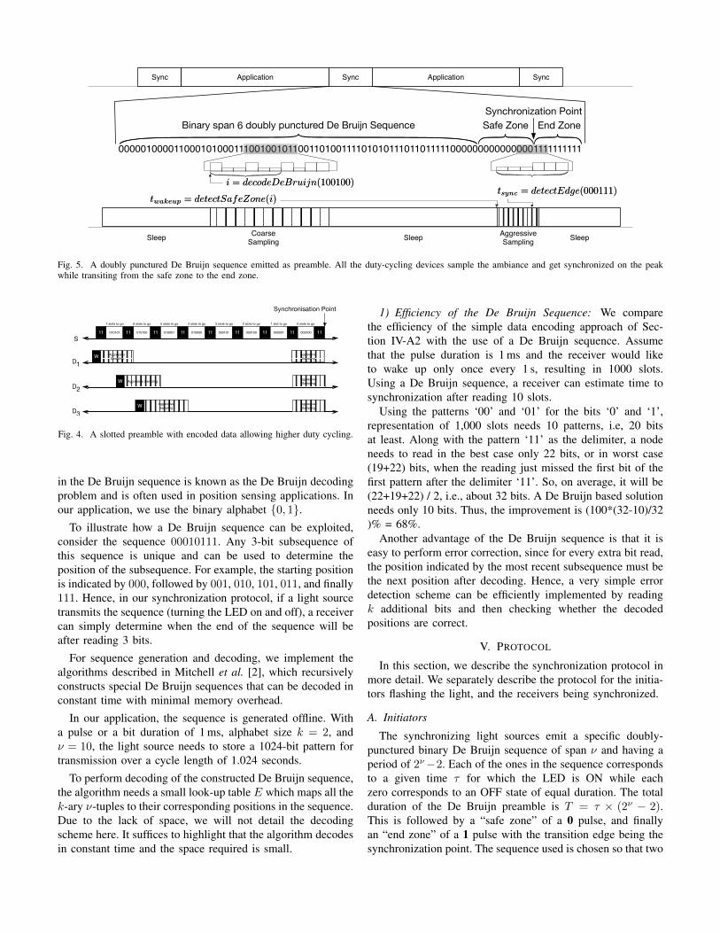
i = decodeDeBruijn(100100)i = decodeDeBruijn(100100)
twakeup = detectSafeZone(i)twakeup = detectSafeZone(i)tsync = detectEdge(000111)tsync = detectEdge(000111)
Fig. 5. A doubly punctured De Bruijn sequence emitted as preamble. All the duty-cycling devices sample the ambiance and get synchronized on the peakwhile transiting from the safe zone to the end zone.
010100
Aggressive Sampling
S
D1
D2
D3
W
W Aggressive Sampling
W Aggressive Sampling
Synchronisation Point
11 010001 11 010000 11 000101 11 000100 11 000001 11 000000 11010101 11
7 slots to go 6 slots to go 5 slots to go 4 slots to go 3 slots to go 2 slots to go 1 slot to go 0 slots to go
11
Aggressive Sampling
Aggressive Sampling
Aggressive Sampling
Fig. 4. A slotted preamble with encoded data allowing higher duty cycling.
in the De Bruijn sequence is known as the De Bruijn decodingproblem and is often used in position sensing applications. Inour application, we use the binary alphabet {0, 1}.
To illustrate how a De Bruijn sequence can be exploited,consider the sequence 00010111. Any 3-bit subsequence ofthis sequence is unique and can be used to determine theposition of the subsequence. For example, the starting positionis indicated by 000, followed by 001, 010, 101, 011, and finally111. Hence, in our synchronization protocol, if a light sourcetransmits the sequence (turning the LED on and off), a receivercan simply determine when the end of the sequence will beafter reading 3 bits.
For sequence generation and decoding, we implement thealgorithms described in Mitchell et al. [2], which recursivelyconstructs special De Bruijn sequences that can be decoded inconstant time with minimal memory overhead.
In our application, the sequence is generated offline. Witha pulse or a bit duration of 1 ms, alphabet size k = 2, andν = 10, the light source needs to store a 1024-bit pattern fortransmission over a cycle length of 1.024 seconds.
To perform decoding of the constructed De Bruijn sequence,the algorithm needs a small look-up table E which maps all thek-ary ν-tuples to their corresponding positions in the sequence.Due to the lack of space, we will not detail the decodingscheme here. It suffices to highlight that the algorithm decodesin constant time and the space required is small.
1) Efficiency of the De Bruijn Sequence: We comparethe efficiency of the simple data encoding approach of Sec-tion IV-A2 with the use of a De Bruijn sequence. Assumethat the pulse duration is 1 ms and the receiver would liketo wake up only once every 1 s, resulting in 1000 slots.Using a De Bruijn sequence, a receiver can estimate time tosynchronization after reading 10 slots.
Using the patterns ‘00’ and ‘01’ for the bits ‘0’ and ‘1’,representation of 1,000 slots needs 10 patterns, i.e, 20 bitsat least. Along with the pattern ‘11’ as the delimiter, a nodeneeds to read in the best case only 22 bits, or in worst case(19+22) bits, when the reading just missed the first bit of thefirst pattern after the delimiter ‘11’. So, on average, it will be(22+19+22) / 2, i.e., about 32 bits. A De Bruijn based solutionneeds only 10 bits. Thus, the improvement is (100*(32-10)/32)% = 68%.
Another advantage of the De Bruijn sequence is that it iseasy to perform error correction, since for every extra bit read,the position indicated by the most recent subsequence must bethe next position after decoding. Hence, a very simple errordetection scheme can be efficiently implemented by readingk additional bits and then checking whether the decodedpositions are correct.
V. PROTOCOL
In this section, we describe the synchronization protocol inmore detail. We separately describe the protocol for the initia-tors flashing the light, and the receivers being synchronized.
A. Initiators
The synchronizing light sources emit a specific doubly-punctured binary De Bruijn sequence of span ν and having aperiod of 2ν−2. Each of the ones in the sequence correspondsto a given time τ for which the LED is ON while eachzero corresponds to an OFF state of equal duration. The totalduration of the De Bruijn preamble is T = τ × (2ν − 2).This is followed by a “safe zone” of a 0 pulse, and finallyan “end zone” of a 1 pulse with the transition edge being thesynchronization point. The sequence used is chosen so that two

⌫ � tuple⌫ � tuple
…001000011000… …001100011000…⌫ � tuple⌫ � tuplekk kk
6th6th
7th7th
8th8th
11th11th
18th18th
8th8th
Fig. 6. Simple error detection algorithm using k additional samples.
specific strings are eliminated. These two strings are all zerosand all ones, as these are natural conditions when the lightis always OFF and always ON respectively. Removing thesetwo states reduces the chance that a device draws a wrongconclusion during normal changes in the light conditions.
B. Receivers
The receivers wake up periodically, at least once in everyinterval whose length depends on the duration of the preamble.When awake, a receiver collects s samples for each of the νsymbols of the emitted binary De Bruijn sequence of span ν.The s × ν samples are collected at a low sampling rate, andthey coarsely represents a unique ν-tuple. A device decodesits position in the preamble to infer unambiguously when thepreamble will end.
After decoding, the device sleeps for the rest of the pream-ble and wakes up during the “safe-zone,” at which point itperforms aggressive sampling at the maximum allowable rateto detect the synchronization point accurately.
C. Preamble Detection
Detection of a ν-tuple is error-prone in a noisy environment.A single bit error in the preamble detection would cause adevice to wake up at an incorrect interval and synchronizeto a wrong edge. For example, detecting 100000 as 100001would make the decoder return 6 instead of 62 for the DeBruijn sequence illustrated in Fig. 5. In this case, the devicewill wake up while the preamble is still being transmittedinstead of in the safe zone.
In order to improve reliability, we adopt a lightweight errordetection mechanism to check the correctness of the sensedsamples. For a binary De Bruijn sequence of span ν, instead ofcollecting samples for ν symbols, we collect for ν+k symbols,where k corresponds to the error detection bits. These samplesfor k additional symbols give us a total of k additional tuplesof the De Bruijn sequence. If correctly sampled, the decodingof each of the (ν + k)-tuples in the ν + k samples should beconsecutive as shown in Fig. 6 and we can correctly calculatethe time to wake up. The value of k can be dynamicallyadjusted depending on how noisy the environment is.
A second issue is that the sleep interval and the length ofsafe-zone have to take into account the maximum clock driftduring the preamble interval. For example, if the maximumclock drift is 20 ppm and preamble length is 10 s, the maxi-mum clock drift is 200 µs either way. Thus, 400 µs of delay isadded, 200 µs to the sleep interval and 200 µs for safe-zone.
CUSUM
60 65 70 75 80 85 90
0 20 40 60 80 100 120 140 160 180
Lux
Sample No
Measured SignalFiltered Signal
0 2 4 6 8
10 12
0 20 40 60 80 100 120 140 160 180
g
Sample No
Up EdgesDown Edges
0 2 4 6 8
10 12
0 20 40 60 80 100 120 140 160 180
g
Sample No
Pulse Edges
Fig. 7. Edge detection algorithm.
D. Synchronization Point Detection
In our protocol, at the synchronization point, the devicessample at the maximum allowed rate to minimize the synchro-nization error. Sampling at high rates causes data explosion,making data storage and offline processing infeasible. Forreal-time synchronization in a noisy environment, in order tohandle this inflow of data, we adopt the Online Change PointDetection Algorithm (CUSUM) [18] with an ExponentiallyWeighted Moving Average filter which we call rlsCUSUM.
For the edge detection algorithm, there is a trade-offbetween MTD (Mean Time to Detection) and FAR (FalseAlarm Rate). Since our objective here is to minimize thesynchronization error between devices, we allow higher FARto reduce MTD.
In order to ensure that false alarms are kept low, we imple-ment another layer of false alarm filtering on top of rlsCUSUMto increase synchronization accuracy further, which we callrlsCUSUM′. In our protocol, we generate a pulse at the endzone of duration τez . With CUSUM in operation for decreasedMTD, we get a number of false upward and downward edgesdue to noises. We mark all those upward and downward edgesas invalid if they fail to satisfy the valid pulse width criteriatupwardEdge − tdownwardEdge ≈ τez . Fig. 7 compares rlsCUSUM(middle) and rlsCUSUM′ (bottom) for samples captured by alight sensor in a noisy environment (top).
VI. IMPLEMENTATION
There are two major components in our system: the synchro-nizers and the devices being synchronized. The synchronizingdevices are light emitters. To validate the feasibility, we havetested different light sources such as simple LED on TelosB,LED lamps and the LED flash on smart phones. In principle,any programmable light source can act as a synchronizer.However, due to interaction with the operating system, highblinking rate with short pulses can only be implemented ondevices with fine grained control over timing. Hence, weimplemented and evaluated the light-based synchronizationprotocol in the Contiki OS [19] and tested on TelosB platform
0
0.1
0.2
0.3
0.4
0.5
0.6
0.7
0.8
0.9
1
0 5 10 15 20 25
Pr(
sync e
rror
<=
x)
sync error(in ticks)
synced with preamblesynced with pulse
Fig. 8. Cumulative sync error using TelosB controlled LED as the lightsource. Pulse width T = 1 ms and k = 10.
with an on-board sensor suite including light, temperature andhumidity sensors.
The protocol uses two levels of light sensor sampling, asdescribed earlier. There is a coarse-grained synchronizationphase using the preamble and a fine-grained synchronizationphase using the final synchronization pulse. Since synchro-nization accuracy depends on the sampling rate, we performsampling at the fastest rate. Light sensors on the TelosBplatform have a rise time of ≈ 0.5 µs with maximum observedsampling interval being ≈ 7 µs. Thus it takes ≈ τsample = 8 µsto turn on, collect an individual sample and go to sleep.
Considering each pulse of duration τ , with 2ν −2 pulses inthe De Bruijn sequence followed by a safe zone and an endzone of τ duration each, the sync phase lasts for 2ν × τ timeperiod.
A. Background Light Intensity Estimation
Before each synchronization phase, we need to obtainan estimate of the background light intensity level. This isrequired to differentiate the ON and OFF pulses during thepreamble sampling phase and also to set the parameters of theedge detection algorithm. This estimation process is performedfor a duration of τnoise (typically a few microseconds) to collecta few samples. The duration is negligible in comparison to theduration of the remaining two sync phases.
B. Preamble Detection
The preamble detection phase involves coarse-grained sam-pling to collect ν-tuple with an additional k error detectionbits from the entire preamble. If sampled correctly, the devicescan decode the correct position of the collected samples in thepreamble and estimate time to the synchronization point.
During this phase, the devices collect s samples for everyν + k pulses of the preamble, thus needing the sensors to beon for (s(ν+k)×τsample). With s = 1 and τsample = 8 µs in ourimplementation, sensors remain on in this phase for τcoarse ≈8(ν + k) µs.
At the end of this stage, a node is already approximatelysynchronized. As the device can sample at any point in thelight pulse, the granularity of the timing is on the order of
0
1
2
3
4
5
6
100us 500us 1ms 5ms 10ms
Synchro
niz
ation E
rror
(Tic
ks)
Pulse Width
Pulse
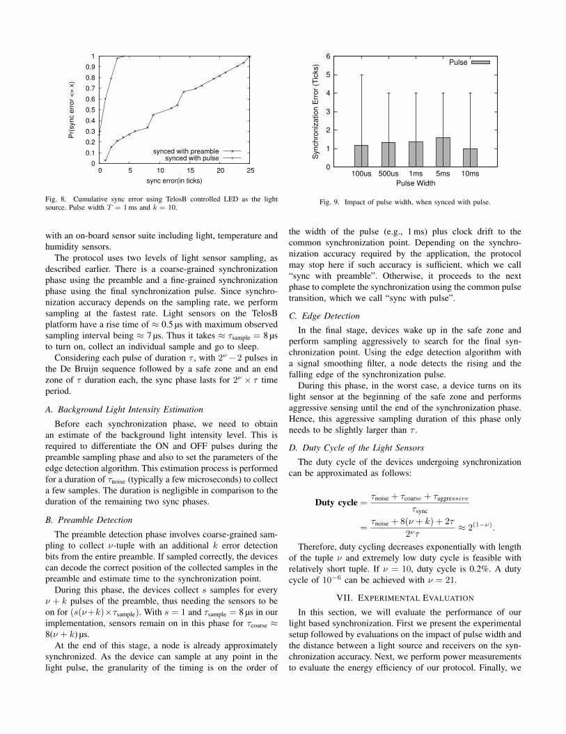
Fig. 9. Impact of pulse width, when synced with pulse.
the width of the pulse (e.g., 1 ms) plus clock drift to thecommon synchronization point. Depending on the synchro-nization accuracy required by the application, the protocolmay stop here if such accuracy is sufficient, which we call“sync with preamble”. Otherwise, it proceeds to the nextphase to complete the synchronization using the common pulsetransition, which we call “sync with pulse”.
C. Edge Detection
In the final stage, devices wake up in the safe zone andperform sampling aggressively to search for the final syn-chronization point. Using the edge detection algorithm witha signal smoothing filter, a node detects the rising and thefalling edge of the synchronization pulse.
During this phase, in the worst case, a device turns on itslight sensor at the beginning of the safe zone and performsaggressive sensing until the end of the synchronization phase.Hence, this aggressive sampling duration of this phase onlyneeds to be slightly larger than τ .
D. Duty Cycle of the Light Sensors
The duty cycle of the devices undergoing synchronizationcan be approximated as follows:
Duty cycle =τnoise + τcoarse + τaggressive
τsync
=τnoise + 8(ν + k) + 2τ
2ντ≈ 2(1−ν).
Therefore, duty cycling decreases exponentially with lengthof the tuple ν and extremely low duty cycle is feasible withrelatively short tuple. If ν = 10, duty cycle is 0.2%. A dutycycle of 10−6 can be achieved with ν = 21.
VII. EXPERIMENTAL EVALUATION
In this section, we will evaluate the performance of ourlight based synchronization. First we present the experimentalsetup followed by evaluations on the impact of pulse width andthe distance between a light source and receivers on the syn-chronization accuracy. Next, we perform power measurementsto evaluate the energy efficiency of our protocol. Finally, we

present experimental results when multiple LEDs send light(with some delays) to a single receiver.
A. Experiment Setup
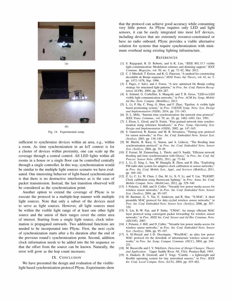
In our experiments, we use a 3 W off-the-shelf LED. Tohave finer control of the light source’s timing, we constructeda simple multi-LED light source controlled by a single TelosBas shown in Fig. 14a. With this setup, the LED can be strictlycontrolled to provide light pulses on a time scale of 100 µs. Inthe evaluation, unless otherwise stated, we set the pulse widthT to be 1 ms, ν to be 10 and the synchronization cycle lastsfor about 1 s.
The receivers in our experiments are TelosB motes runningContiki. The default built-in light sensor is used. After thesynchronization is completed, a packet transmission is ini-tiated to the receiver(s). We measure the accuracy of timesynchronization by comparing the clock obtained by oursynchronization protocol with the clock obtained using aGlossy-like synchronization protocol that reads the local clockimmediately after the packet reception. Time is measured inunits of clock ticks where one clock tick is approximately32 µs.
B. Synchronization Accuracy
We measure the performance of two different approaches:the full protocol that synchronizes all nodes on a single transi-tion, and the approximate scheme where devices synchronizeusing only the preamble. In this experiment, the light sourceand the receiver are kept close enough so that the light pulsecan be detected with minimum error.
In Fig. 8, the cumulative error distributions of both theschemes using a TelosB/LED as the light source are shown.We can see that the full PSync scheme is able to achieveaverage error of 1.3 clock ticks, with a maximum error around4 clock ticks. For the approximate scheme, since sampling isdone at a low rate, the error is much larger. The average erroris 11 clock ticks and the maximum error reaches the durationof one pulse width of 1 ms or 32 clock ticks.
For the scheme that attempts to synchronize using onlythe preamble, the inaccuracy is mainly caused by differentsampling positions in a bit, i.e., where the two motes sensedifferent time points of one bit in the preamble.
We also evaluate the impact of pulse width on the synchro-nization accuracy by varying the pulse width from 100 µs to10 ms. As shown in Fig. 9, since the synchronization pointis based on transition, as expected, pulse width has fairlyminimum impact on accuracy.
C. Power Measurement
We measure the power consumption of running PSync inTelosB motes, the platform we used to implement our algo-rithm. Power measurements are performed using the Monsoonpower meter.
PSync has two main stages that consume power, the coarsesampling period and the aggressive sampling period. Wemeasure the power consumption of the two stages and compare
0
2
4
6
8
10
0 200 400 600 800 1000
Pow
er
consum
ption r
ate
(m
W)
Time (ms)
(a) Idle states power consumption.
0
2
4
6
8
10
0 200 400 600 800 1000
Pow
er
consum
ption r
ate
(m
W)
Time (ms)
(b) Light sync power consumption.
0
10
20
30
40
50
60
70
0 200 400 600 800 1000
Pow
er
consum
ption r
ate
(m
W)
Time (ms)
(c) Radio sync power consumption.
Fig. 10. Power profiles for different operations: (a) CPU idle, (b) runningPSync every second, (c) reception of a 1-byte packet over IEEE 802.15.4radio.
with the power consumed by radio based synchronizationprotocol. As a baseline for radio based synchronization, weconsider the power consumed by receiving a small 1-bytepacket using the IEEE 802.15.4 radio at 2.4 GHz on theTelosB. The sender is programmed to transmit one smallpacket per second. The results are shown in Fig. 10.
Fig. 10a shows the power profile when the CPU is idle.The processor wakes up periodically triggered by timer events.The power consumption rate varies from 1.73 mW to 6.52 mW,with an average of 2.01 mW.
Fig. 10b shows the power profile when PSync is run usinga pulse width of 1 ms. The power consumption varies from2.00 mW to 8.00 mW and the additional energy consumed onperforming one cycle of PSync is 57.49 µJ.
Fig. 10c shows the power profile when a single 1-bytepacket is received. The power consumption varies from 2 mWto 70 mW and the additional energy consumed is 171.61 µJ.
As the processing is relatively simple, the major powerconsumption in PSync is actually the energy consumed to turnthe light sensor ON for the duration of the coarse sampling

0
1
2
3
4
5
6
10cm 20cm 30cm 40cm 50cm 60cm
Synchro
niz
ation E
rror
(Tic
ks)
Distance (cm)
Pulse
Fig. 11. Synchronization error of PSync when varying distances.
period. Further, once a light sensor on the TelosB is turnedon, it stays on for at least 2 ms to 3 ms. Nevertheless, thesampling duration can be shortened if a shorter pulse widthis used. With a smaller pulse width of 0.5 ms and 0.1 ms, theadditional energy consumed to perform one cycle of PSyncreduces to 32.43 µJ and 20.42 µJ respectively.
D. Varying Distances
In this evaluation, we investigate how the accuracy varieswith distance between the light source and the devices to besynchronized. Using the 3 W off-the-shelf power by batteryand controlled by TelosB, the distance up to which one cansafely synchronize is observed to be 60 cm as illustrated inFig. 11. While the error does increase slightly as the distanceincreases, the average error is still less than 2 ticks, even atthe maximum distance evaluated.
In order to increase the distance between sender and re-ceiver, one can either increase the intensity of the light sourceor the sensitivity of the light sensor. In the next experiment, wemeasure the light intensity between a stronger light source (anoff-the-shelf 9 W LED light bulb) and a more sensitive lightsensor (the light sensor on the Galaxy S II). Fig. 12 shows thecorresponding results. It can be seen that the sensing range hasincreased to more than 5 m. The use of an even brighter sourceor a more sensitive light sensor will increase the sensing rangefurther.
E. Multiple Light Source
One potential challenge for application of light based syn-chronization is that a sender might not be able to correctlyreceive a signal from multiple light generators. Multi-hopsynchronization might also be needed when devices are spreadover a larger area.
We investigate the sub-problem whereby a receiver candetect light from 2 sources. Problem happens when these 2sources are not well synchronized, leading to the transmittedsequences going out of sync. This can cause difficulty for thereceiver to decode the sequence. A similar challenge exists ina radio based protocol, which can be mitigated by exploitingconstructive wireless interference and capture effect.
1
10
100
1000
10000
20 40 60 80 100 200 300 400 500 600
Lux
Distance (cm)
Fig. 12. Light Intensity vs. distance using a 9 W LED and light sensor onGalaxy S II.
50
60
70
80
90
100
0 10 20 30 40 50 60
Perc
enta
ge o
f va
lid 1
0 b
it
De
Bru
ijn s
ub
seq
uen
ces
Inter-flash delay (d) between different source (in rtimer ticks)
Pulse width = 32 ticks
Pulse width = 64 ticks
Pulse width = 128 ticks
Fig. 13. Plot showing the percentage of valid subsequences of a De Bruijnsequence decoded by a receiver with two concurrent light sources flashingwith varying delays.
In this experiment, we look at the impact of slight offsetbetween preamble generated by two light sources on its suc-cessful decoding. The experimental setup is shown in Fig. 14b.The sender has 1 TelosB controlling 6 LEDs through a drivercircuit. In the experiment, 2 randomly selected LEDs areused. We vary the offset between the LED transmissions andcheck the reception reliability by calculating how likely thereceiver can decode the preamble represented by the ratio ofthe number of correctly decoded 10-bit subsequences out ofthe 1022 possible subsequences. The result shown in Fig. 13suggests that in the worst case, 85% of the 10-bit subsequencecan be correctly received.
Recall that for correct decoding, all we need is for thereceiver to be able to correctly decode just ν + k bits out ofthe 2ν bits of the De Bruijn sequence. If an error is detected,the receiver simply moves on to later part of the preamble andrestart decoding. Based on the result in Fig. 13, we can seethat as long as the delay between the light sources is a smallfraction of the pulse width, it is very likely that a receiver cancorrectly decode the ν + k sub-sequences.
VIII. DISCUSSION
So far, PSync has mainly been evaluated in scenarios wherethe receiver can sense a light directly from the light source.In many deployments, a typical LED light bulb would be
(a)
(b)
Fig. 14. Experimental setup.
sufficient to synchronize devices within an area, e.g., withina room. As time synchronization in an IoT context is fora cluster of devices within proximity, one can scale up thecoverage through a central control. All LED lights within allrooms in a house or a single floor can be controlled centrallythrough a single controller. In this way, synchronization wouldbe similar to the multiple light sources scenario we have eval-uated. One interesting behavior of light-based synchronizationis that there is no destructive interference as is the case ofpacket transmission. Instead, the last transition observed willbe considered as the synchronization point.
Another option to extend the coverage of PSync is toexecute the protocol in a multiple-hop manner with multiplelight sources. Note that only a subset of the devices needto serve as light sources. However, all light sources mustbe within the visible light range of at least one other lightsource and the union of their ranges cover the entire areaof interest. Starting from a single light source, clock infor-mation is propagated outwards. Two additional functions areneeded to be incorporated into PSync. First, the next cycleof synchronization starts after a fix duration after the end ofthe previous round’s synchronization point. Second, additionclock information needs to be added into the bit sequence sothat the offset from the source can be known. Naturally, theerror will grow as the hop count increases.
IX. CONCLUSION
We have presented the design and evaluation of the visible-light based synchronization protocol PSync. Experiments show
that the protocol can achieve good accuracy while consumingvery little power. As PSync requires only LED and lightsensors, it can be easily integrated into most IoT devices,including devices that are extremely resource-constrained orhave no radio onboard. PSync provides a viable alternativesolution for systems that require synchronization with mini-mum overhead using existing lighting infrastructure.
REFERENCES
[1] S. Rajagopal, R. D. Roberts, and S.-K. Lim, “IEEE 802.15.7 visiblelight communication: Modulation schemes and dimming support,” IEEECommun. Magazine, vol. 50, no. 3, pp. 72–82, Mar. 2012.
[2] C. J. Mitchell, T. Etzion, and K. G. Paterson, “A method for constructingdecodable de Bruijn sequences,” IEEE Trans. Inf. Theory, vol. 42, no. 5,pp. 1472–1478, Sep. 1996.
[3] J. Pages, J. Salvi, and J. Forest, “A new optimised De Bruijn codingstrategy for structured light patterns,” in Proc. Int. Conf. Pattern Recog-nition (ICPR), 2004, pp. 284–287.
[4] S. Schmid, G. Corbellini, S. Mangold, and T. R. Gross, “LED-to-LEDvisible light communication networks,” in Proc. ACM Int. Symp. MobileAd Hoc Netw. Comput. (MobiHoc), 2013.
[5] L. Li, P. Hu, C. Peng, G. Shen, and F. Zhao, “Epsilon: A visible lightbased positioning system,” in Proc. USENIX Symp. Netw. Syst. Designand Implementation (NSDI), 2014, pp. 331–343.
[6] D. L. Mills, “Internet time synchronization: the network time protocol,”IEEE Trans. Commun., vol. 39, no. 20, pp. 1482–1493, Oct. 1991.
[7] J. Elson, L. Girod, and D. Estrin, “Fine-grained network time synchro-nization using reference broadcasts,” in Proc. Symp. Operating Syst.Design and Implementation (OSDI), 2002, pp. 147–163.
[8] S. Ganeriwal, R. Kumar, and M. B. Srivastava, “Timing-sync protocolfor sensor networks,” in Proc. Int. Conf. Embedded Netw. Sensor Syst.(SenSys), 2003, pp. 138–149.
[9] M. Maroti, B. Kusy, G. Simon, and A. Ledeczi, “The flooding timesynchronization protocol,” in Proc. Int. Conf. Embedded Netw. SensorSyst. (SenSys), 2004, pp. 39–49.
[10] F. Ferrari, M. Zimmerling, L. Thiele, and O. Saukh, “Efficient networkflooding and time synchronization with Glossy,” in Proc. Int. Conf. Inf.Process. Sensor Netw. (IPSN), 2011, pp. 73–84.
[11] L. Li, G. Xing, L. Sun, W. Huangfu, R. Zhou, and H. Zhu, “ExploitingFM radio data system for adaptive clock calibration in sensor networks,”in Proc. Int. Conf. Mobile Syst., Appl., and Services (MobiSys), 2011,pp. 169–182.
[12] Z. Li, C. Li, W. Chen, J. Dai, M. Li, X.-Y. Li, and Y. Liu, “FLIGHT:Clock calibration using fluorescent lighting,” in Proc. Annu. Int. Conf.Mobile Comput. Netw. (MobiCom), 2012, pp. 329–340.
[13] J. Polastre, J. Hill, and D. Culler, “Versatile low power media access forwireless sensor networks,” in Proc. Int. Conf. Embedded Netw. SensorSyst. (SenSys), 2004, pp. 95–107.
[14] M. Buettner, G. V. Yee, E. Anderson, and R. Han, “X-MAC: A shortpreamble MAC protocol for duty-cycled wireless sensor networks,” inProc. Int. Conf. Embedded Netw. Sensor Syst. (SenSys), 2006, pp. 307–320.
[15] S. Liu, K.-W. Fan, and P. Sinha, “CMAC: An energy efficient MAClayer protocol using convergent packet forwarding for wireless sensornetworks,” in Proc. IEEE Int. Conf. Sensor and Ad Hoc Commun. Netw.(SECON), 2007.
[16] J. Polastre, J. Hill, and D. Culler, “Versatile low power media access forwireless sensor networks,” in Proc. Int. Conf. Embedded Netw. SensorSyst. (SenSys), 2004, pp. 95–107.
[17] A. El-Hoiydi and J.-D. Decotignie, “WiseMAC: an ultra low powerMAC protocol for the downlink of infrastructure wireless sensor net-works,” in Proc. Int. Symp. Comput. Commun. (ISCC), 2004, pp. 244–251.
[18] M. Basseville and I. V. Nikiforov, Detection of Abrupt Changes: Theoryand Application. Upper Saddle River, NJ, USA: Prentice-Hall, 1993.
[19] A. Dunkels, B. Gronvall, and T. Voigt, “Contiki – a lightweight andflexible operating system for tiny networked sensors,” in Proc. IEEEInt. Conf. Local Comput. Netw. (LCN), 2004, pp. 455–462.