Embed Size (px)
Citation preview

ICESTARS – FP7/2009/ICT/214911 –D5.5
Public
Confidential
Project: ICESTARS
Project Number: FP7/2008/ICT/214911
Work Package: WP5
Task: T5.4
Deliverable: D5.5 (version 1.2)
Title: Public Validation Report
Author(s): Rick Janssen, Hans Georg Brachtendorf, Taisto Tinttunen, Janne Aikio, Timo Rahkonen, Wim Schoenmaker, Monica Selva Soto, Kai Bittner, Emira Dautbegovic, Jan ter Maten, Roland Pulch
Affiliation(s): NXP, FHO, APL, OUL, MAG, KLN, WUP, IFX
Date: 19-November-2010

ICESTARS – FP7/2009/ICT/214911 –D5.5 - 2 -
Table of Contents
1 Introduction ................................................................................................. 3 2 Validation plan description ........................................................................ 4 3 WP1 validation activities ............................................................................ 5 4 WP2 validation activities ............................................................................ 8
4.1 Harmonic Balance (HB) Algorithmic items ............................................. 8 4.2 Volterra-on-HB (VoHB) .......................................................................... 9
5 WP3 validation activities .......................................................................... 11 6 Comparison with the state-of-the-art and conclusions ......................... 13
6.1 WP1..................................................................................................... 13 6.2 WP2..................................................................................................... 14 6.3 WP3..................................................................................................... 15 6.4 General conclusion .............................................................................. 18

ICESTARS – FP7/2009/ICT/214911 –D5.5 - 3 -
1 Introduction ICESTARS (Integrated Circuit/EM Simulation and Design Technologies for Advanced Radio Systems-on-chips) is a collaborative research project within the research program "Information and communication technologies" (ICT) of the Seventh Framework Programme for Research and Technological Development (FP7) funded by the European Union (EU). ICESTARS addresses a series of critical issues or "bottlenecks" in the currently-available infrastructure for the design and simulation of new and highly-complex Radio Frequency (RF) front ends operating beyond 10 and up to 100 GHz. Future systems demand an increasing blend of analogue and digital functionalities. The ICESTARS research will accelerate the chip development process in the extremely high frequency (EHF) range to accomplish future demands for higher capacity channels. The key to enable the realization of single-chip integration of high-GHz wireless modules is resolving the shortcomings in available design flows. ICESTARS aims at an efficient connection between the frequency domain – where the RF part of wireless transceiver systems is usually designed – with the time domain where the digital signal processing and control logic are generally developed. ICESTARS will introduce not only novel Computer Aided Design (CAD) tools but also the mathematical methods to deal with analogue/digital mixed signal simulation and future challenges in system design and methodologies, thus enabling European developers of integrated circuits (IC) for RF (RF-IC) to maintain their top position at the global telecommunication market. In the first phase of the project an inventory of available test cases (repository) that cover the complete range of possible expected problem areas to be solved in the project was performed. Based on this repository an algorithm/tool development test set was created to serve as working material for the RTD work packages WP1-WP3. Together with tool developers, formats were specified for the pseudo code and reporting. This was done to ensure that compatibility with the industrial circuit simulators is maintained. Related to this, work was performed in task T5.4: “Validation of developments and final tuning”. A comprehensive validation of developed algorithms/ tools was done using the test cases from the development test set. Here the accuracy of the prototype solutions/algorithms was determined by comparing simulations and measurements. During this phase feedback was given, such that some final fine-tuning could be done on the prototype toolset, where necessary. This document is the public version of the outcome of this specific task in workpackage WP5 on validation.

ICESTARS – FP7/2009/ICT/214911 –D5.5 - 4 -
2 Validation plan description The validation plan was based on the test benches/examples, as described in D5.1, “Tool Development Test Set”, which gave coverage of the complete functionality of the tools to be developed. This also gave a rough description of when and what in terms of validation, including test benches and timing.
Task Example
1.1 1.2 1.3 2.1 2.2 2.3 2.4 2.5 3.x
transAmp x x x x x x
c9linmix x x xx x x x x
vcoBi x x x x
vcoBi+ Mosfet model x x x x x
LNA model x x
IQ Modulator x x x
IQ Demodulator x x x
QPSK receiver x x
PLL xx x x
PA x x x x
Colpitts oscillator x x x x
Pierce oscillator x x x x
VHF oscillator x x x x
Switch capacitor x
Driscol oscillator xx
Schmitt Trigger xx
Inverter chain xx
Diode mixer xx
Gilbert cell mixer xx
Low voltage mixer xx
Single balanced mixer xx
Folded switching mixer xx
Table 1: validation coverage of development tasks with available test cases (x = baseline test case, xx = possible additional test case).
During the validation process it was decided to look for an example which could be used as a test case for all workpackages, so that results from different workpackages could be compared against each other, which effectively was a test of the different circuit simulators in the project (TITAN, APLAC, MECS and LinzFrame (FHO)) on the same example and the Magwel EM solver. In order to use the test circuit with the different simulators, a transistor model had to be used which could be handled by all simulators. For this purpose a simple level 1 Mosfet model (Shichman-Hodges) was taken.

ICESTARS – FP7/2009/ICT/214911 –D5.5 - 5 -
3 WP1 validation activities The activities in WP1 “Time domain techniques” covered the development of novel circuit simulation algorithms based on wavelet approximations as well as multiscale algorithms. The wavelet-based algorithm is intended to complement and/or replace standard time-domain techniques such as transient analysis. The validation of wavelet methods was performed for the different classes of RF circuits of the test bench ranging from amplifiers to mixers and oscillators. The versatile circuit types lead to a fair comparison regarding accuracy and speed with existing highly-optimized transient analysis. For example, Figure 1 shows the outcome of the validation of the developed wavelet technique against transient analysis on the mixer (c9linmix) test circuit.
Figure 1: Input and Output signal for the mixer (c9linmix).
The results of the performed validation indicate that the wavelet-based method is able to fulfill all accuracy requirements and may achieve the performance of the standard transient analysis. Since the relatively new wavelet approach has a large potential for further optimization, both in algorithmic terms as well as software implementation, we are optimistic that wavelet analysis will be a valuable tool for circuit simulation in the future. Therefore we intend to continue activities on optimization and further development of the wavelet-based algorithm beyond the project duration. Another activity of WP1 deals with multiscale or multirate circuits. Common to all these circuits is the sparsity of the signal spectrum. Standard methods are prohibitive due to their long run times caused by the often spurious frequencies

ICESTARS – FP7/2009/ICT/214911 –D5.5 - 6 -
and artifacts. The novel methods developed so far deal specifically with these circuits, which are used in transceiver front-ends. Test examples include high quality oscillators as well as PLLs. Due to their high quality the settling time of the oscillators is orders of magnitude larger than the oscillation period, i.e., the envelope of the signal is a lowpass signal compared with the oscillation frequency. An even more severe problem is the simulation of PLLs. The high frequencies of the VCO contrasts with the lowpass signal at the output of the loop filter. Standard techniques lead to severe run times. The PLL test example was used for the improvement of the specific envelope simulation engines developed in the context of WP1. The multirate technique employed in WP1 basically reformulated the underlying system of ordinary differential-algebraic equations (DAE) by a system of partial differential equations (PDE), which has been developed in recent years. The solution of the underlying ordinary DAE is obtained along a specific solution curve referred to as the characteristic of the PDE. The reformulation depends on the circuit under test, i.e., there is no one-to-one correspondence between the ordinary and partial DAEs. In this project the method has been applied to autonomous circuits, i.e., oscillators and non-autonomous systems specifically mixer circuits. Figure 2 below illustrates the technique employing a Driscol quartz crystal oscillator test example. Firstly, one observes an oscillatory behavior in the t1 coordinate and a smooth curve in the τ coordinate. Moreover, the time scales are significantly different which is the cause for the efficiency of the technique. The
signal of the oscillator output is obtained along the curve tt == τ1 . One can see,
that after 50 ms the initial transient response is settled, whereas the oscillator frequency is about 0.5 MHz.
Figure 2: Solution of Driscol quartz crystal oscillator using multirate technique

ICESTARS – FP7/2009/ICT/214911 –D5.5 - 7 -
Figure 3 below shows the output of a single balanced mixer in the uplink. As an input signal a sinusoidal source is chosen, which represents the large time scale along the t axis. The RF oscillator signal is here normalized in radians.
Figure 3: Solution of single balanced mixer in uplink
The figures above have been derived by the multirate PDE formulation using spline wavelets. An alternative method for the multirate PDE formulation is the Sweep Following Method that dynamically updates the local frequency function according to an optimization criterion. This method has been tested for autonomous and non-autonomous (driven) oscillators. The reconstruction of the solution of the original problem uses a reconstruction formula that is similar as for the spline wavelet PDE method. The Sweep Following Method determines envelopes in an efficient way. The method applies both to amplitude and to frequency modulated problems.

ICESTARS – FP7/2009/ICT/214911 –D5.5 - 8 -
4 WP2 validation activities
The activities in WP2 deal mainly with the Harmonic Balance (HB) algorithm as well as VoHB (Volterra-on-HB) which utilizes Harmonic Balance as one step of the whole analysis.
4.1 Harmonic Balance (HB) Algorithmic items
In purely HB related items, we have different goals depending on the tasks:
1. Ability to perform analysis on the circuit, i.e., method availability and convergence.
2. Analysis speed has increased when compared to the previous algorithm. 3. Analysis consumes less memory than the analysis using the old algorithm. 4. Internal balancing of the analysis has changed so that it is better suited for
multithreading (e.g., some well-scaled task dominates more). 5. Better initial estimates for Harmonic Balance Oscillator problems.
For HB analysis, the adaptivity has been tested by forcing the test circuits to a state where the convergence is poor. This can be done by increasing the power level, which in turn increases the circuit nonlinearity. This showed the algorithms ability to treat poor convergence.

ICESTARS – FP7/2009/ICT/214911 –D5.5 - 9 -
Figure 4: Multithreading scalability when the circuit is multiplied with a factor of 2 – 200. Both nodal and piece-wise algorithms show the same trend. The new implementation maintains the scaling as the circuit size grows.
Scalability for larger circuits could be tested by copying a large circuit so that there are several instances of it. If the algorithms had bottlenecks for the number of nodes, elements, etc. such a test would have made them visible. In Figure 4 the multithreading scalability is shown as a function of circuit size. The analysis speed was tested by running several analysis tasks and averaging the simulation time. Tests were run in both single and multithreaded mode. When simulations were run, they are done mainly using less CPUs/cores than the maximum number. This assures that occasional loads due to e.g., virus scanning, do not affect the simulation times. For free-running (autonomous) oscillators initial estimates have been derived by extracting information from a limited time integration. These techniques have been thoroughly tested. In most cases these approaches led to a reduced number of iterations in the HB method (and also make HB applicable to a larger set of problems). However some problems indicated the need for further improvements of the estimates as well as in improving HB itself. One vector extrapolation technique was developed to improve estimates. For HB a dynamically updated gauge equation was derived. These last emerging techniques have only been limitedly tested yet.
4.2 Volterra-on-HB (VoHB)
VoHB analysis tests were done for PA circuits. At first some tests were run using the old APLAC input language based models. These results were then compared to the results that the new APLAC analyzer interface (AIF) model produced. This verified that the new improved implementation is correct. The new model is able to run a larger set of tests. These were run and their results verified by simulating the circuits with terminations that the VoHB analysis has proposed. The results showed that the suggested termination results in minimized distortion at the PA output. The improved VoHB technique also enables new features such as detailed distortion analysis of circuits including several nonlinear devices as well as analysis using multitone excitations. The testing of the improved VoHB technique was carried out using four different test setups. 30W LDMOS RF PA and HBT PA test benches were used for comparison between old and new VoHB techniques. The transAmp LNA and c9linmix mixer circuit were also used with VoHB as they contain several nonlinear devices and BSIM3 device models that have not been tested with VoHB before. The c9linmix circuit sets the analysis power of VoHB to its limit as we need to have 3-tone analysis and a circuit driven with a large LO signal for nonlinear analysis. Yet the VoHB technique was verified as a dimensioning tool for PA design by a harmonic impedance load pull

ICESTARS – FP7/2009/ICT/214911 –D5.5 - 10 -
technique. The results showed that the suggested termination results in minimized distortion at the PA output. As a validation example in Figure 5 a plot is made comparing the VoHB fitting results and HB results for an LDMOS PA test bench, showing good accuracy. When comparing simulation times between HB and Volterra, 4·80·80 load pull points are calculated meaning almost 26000 analyses. For HB this means 13 minutes but only 2.5 minutes in Volterra calculation.
Figure 5: Plot of accuracy VoHB against HB method
ICESTARS – FP7/2009/ICT/214911 –D5.5 - 11 -
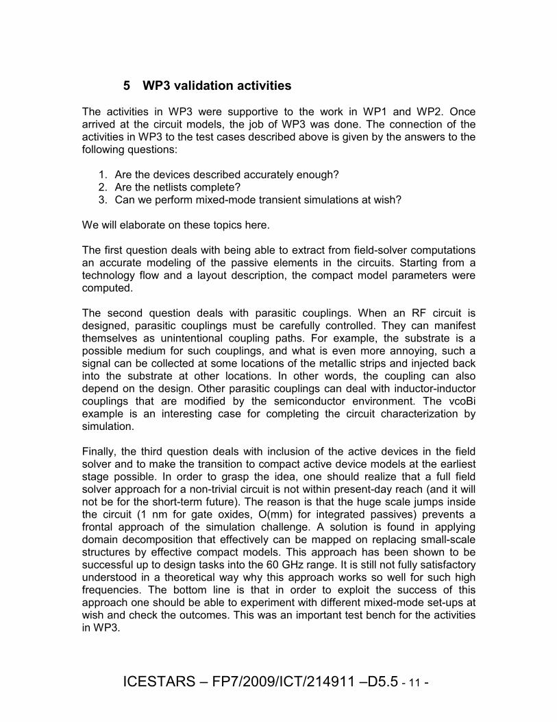
5 WP3 validation activities The activities in WP3 were supportive to the work in WP1 and WP2. Once arrived at the circuit models, the job of WP3 was done. The connection of the activities in WP3 to the test cases described above is given by the answers to the following questions:
1. Are the devices described accurately enough? 2. Are the netlists complete? 3. Can we perform mixed-mode transient simulations at wish?
We will elaborate on these topics here. The first question deals with being able to extract from field-solver computations an accurate modeling of the passive elements in the circuits. Starting from a technology flow and a layout description, the compact model parameters were computed. The second question deals with parasitic couplings. When an RF circuit is designed, parasitic couplings must be carefully controlled. They can manifest themselves as unintentional coupling paths. For example, the substrate is a possible medium for such couplings, and what is even more annoying, such a signal can be collected at some locations of the metallic strips and injected back into the substrate at other locations. In other words, the coupling can also depend on the design. Other parasitic couplings can deal with inductor-inductor couplings that are modified by the semiconductor environment. The vcoBi example is an interesting case for completing the circuit characterization by simulation. Finally, the third question deals with inclusion of the active devices in the field solver and to make the transition to compact active device models at the earliest stage possible. In order to grasp the idea, one should realize that a full field solver approach for a non-trivial circuit is not within present-day reach (and it will not be for the short-term future). The reason is that the huge scale jumps inside the circuit (1 nm for gate oxides, O(mm) for integrated passives) prevents a frontal approach of the simulation challenge. A solution is found in applying domain decomposition that effectively can be mapped on replacing small-scale structures by effective compact models. This approach has been shown to be successful up to design tasks into the 60 GHz range. It is still not fully satisfactory understood in a theoretical way why this approach works so well for such high frequencies. The bottom line is that in order to exploit the success of this approach one should be able to experiment with different mixed-mode set-ups at wish and check the outcomes. This was an important test bench for the activities in WP3.

ICESTARS – FP7/2009/ICT/214911 –D5.5 - 12 -
The capability to ‘experiment at wish’ with different mixed mode set-ups was scheduled parallel to main-stream developments in WP3 in the ICESTARS project. The first method is based on building an interface to the MECS solver, whose key algorithm solves the time-based evolution of dynamical systems and the MAGWEL solver whose role in this approach is to set up the device structure for a field solving approach (layout, mesh, boundary conditions) and to formulate the coupling equations for the field variables. In the second approach, the MAGWEL solver was itself equipped with a transient module that allows time integration for time-dependent voltages at ports. The MAGWEL solver was also equipped with the capability to attach compact models at contacts. Validation is seen as demonstrating successful uses of these new developments, thereby providing the environment for performing numerical experiments as described above. In particular, the validation requires that the transient mixed-mode equations can be solved using the standard linear solver methods and that the number of iterations does not exceed much the required number for solving the time-independent system. For the MAGWEL compact model library, the following devices were made available
• PNP transistor
• NPN transistor
• PN diode For the MOS compact model the circuit simulator and the transient solver MECS was exploited. As an example of the results obtained in WP3 consider the following test case. In order to test the correct transient behavior of the coupled field-circuit simulation with a large EM model, we simulated a simple self oscillating circuit combining an octo-shaped inductor with one capacitance. The results are presented in Figure 6. showing a damped self-oscillating behavior.
Figure 6: Coupled field-circuit simulation (MAGWEL-MECS) of an octo-shaped inductor (left) and a capacitance in series. The output voltage is shown on the right.

ICESTARS – FP7/2009/ICT/214911 –D5.5 - 13 -
6 Comparison with the state-of-the-art and conclusions
6.1 WP1
A novel wavelet-based algorithm for mixed analog-digital circuit simulation has been developed within the ICESTARS project. A prototype of the code implementation is available in Infineon's in-house circuit simulator TITAN and this prototype is successfully validated against the ICESTARS benchmark set (see D5.2). To the best of our knowledge no other productively used circuit simulator (either in-house or commercially available) features a working wavelet-based algorithm for circuit simulation. We are however aware of one experimental version of a wavelet method for circuit simulation, which is offered in the open source circuit simulator FREEDA (www.freeda.org). FREEDA is a multi-physics simulator under development by a user community from universities, research communities and laboratories. It has its own netlist format and uses state variables internally, unlike standard SPICE-like simulators. However, the FREEDA wavelet approach does not exploit the advantages of an adaptive wavelet expansion as in the ICESTARS approach and has stability problems as pointed out on page 8 of the v1.3 of the FREEDA User manual. In the last released version (v1.4) (status October 2010), the status of the wavelet implementation seems to be unchanged and we have indications from direct contacts with a FREEDA team member that the development of the wavelet analysis in this simulator is suspended. Envelope techniques are available in the commercial simulator engines EldoRF (Mentor Graphics) and ADS (Agilent). The implementation in ADS is not based on the PDE approach used by this project team. Instead, it is based on a patent by D. Sharrit, “Method for simulating a circuit”, which is a Harmonic Balance method with time varying Fourier coefficients. The method lacks a strict mathematical basis. From the manual of EldoRF it is not clear which technique has been adopted. The key researcher (D. Lee) is however aware of the PDE techniques developed by Brachtendorf et al. SpectreRF (Cadence) employs steady state techniques (HB and shooting). To the best of the author’s knowledge no envelope technique has been adopted. An envelope technique has been implemented at Sandia National Laboratories (Albuquerque) which has not been commercialized and is not available for external users.
Concerning multi-time approaches (multirate/multitone in our reports) the in-house circuit simulator Xyce of Sandia National Laboratories offers this, based on the work by Prof. Jaijeet Roychowdhury (see: http://xyce.sandia.gov). Sandia's implementation does not include wavelets or Sweep Following (or the optimal time splitting). Furthermore, this circuit simulator is not available for industrial purposes.

ICESTARS – FP7/2009/ICT/214911 –D5.5 - 14 -
Envelope simulation for autonomous and non-autonomous oscillators is available in PAN (http://brambilla.elet.polimi.it), the circuit simulator of Prof. Angelo Brambilla. This refers to the work by his colleague Paolo Maffezoni. PAN also determines PSS by shooting.
6.2 WP2
For Harmonic Balance analysis, the APLAC simulator is a commercial, well known and widely used tool and is one of the few remaining commercial simulators. In that sense, on a larger scale, it is the state-of-the-art. Naturally every simulator has its strong parts when compared to others. APLAC is a multipurpose simulator; it is used in simulating RFICs, MMICs as well as pure RF circuits. In other words, the simulation can be run for thousands of BSIM3s or just a single LDMOS based power amplifier. Some simulators only support analog models (Spice based simulators, like HSpice from Synopsys). There are also simulators that do not support the necessary models for PA design, such as FDD elements needed to simulate X-parameter models. Some simulators also lack a time-domain solver using the same model base. That excludes e.g., transient assisted methods – but simplifies the simulator structure as all linear models can be represented as y-parameters. APLAC supports all of these – naturally making it quite hard to be optimal in every part – with default settings. HB analysis scaling for multiple threads has been improved in APLAC simulator. The feature itself, multithreaded HB is available in most of the other commercial HB simulators as well (EldoRF, ADS). The quality of the implementation is not known but the statements in e.g., EldoRF manual (v6.6 from 2005) gives some insight to the state-of-the art. "With a two processor machine, the elapsed time gain is about 25% compared to the use of a single processor. This gain can reach 45% using four processors." In practice that means a 100 second simulation would take 75 seconds, i.e., the threading efficiency would be around 50%. In APLAC, this efficiency was achieved for circuits not suitable for multithreading (large linear dominant circuit in validation) and would mean a speed-up of 1.34. APLAC multithreading speed-up is between 1.5 (PAs, other circuits with few nonlinear elements) and 1.8 (e.g., large RFICs) for practical problems, depending on the circuit type. The scalability for large multitone frequency sets has been improved. The designers do not ask for a better support for 5 or 6-tone simulations mainly because it is thought that it is a problem that cannot be solved. However, the tests run for the Freescale PA with realistic biasing and matching networks showed that it is possible to run a 5-tone simulation so that a single (1st) point takes only a few seconds to solve, depending on frequency truncation. In practice that means a power or frequency sweep with tens of points can be simulated in minutes, not in hours.

ICESTARS – FP7/2009/ICT/214911 –D5.5 - 15 -
The state-of-the-art HB simulators rely on inexact-Newton GMRES based iteration. There are no competing methods used in commercial simulators. We integrated the state-of-the-art tensor solver from Sandia National Laboratories into APLAC. The Trilinos framework offers another high quality solver and is useful as a back-up solution in case the inexact-Newton solver fails. Previously, there have not been other options than switching to a basic Newton solver. The Trilinos solver was found faster for some of the test cases simulated so it has proven its potential. More robust and faster HB oscillator analysis has been developed. Improved initial guess is based on time-domain simulation. Transient assisted HB is not known to be used in other tools in finding out the oscillation frequency. Transient assisted HB is used in some tools as convergence aid but it is assumed that the frequency is already known from e.g., some earlier transient simulation. Frequency adaptivity was added to be able to change the frequency set during the simulation. It enables accuracy refinement so that the aliasing effects can be minimized. This feature is not available in any other commercial tool. Adaptivity was also added for changing the preconditioner if the number of GMRES iterations grew significantly. The ability to change preconditioner during the analysis is not available in other commercial simulators. Additionally, a new hierarchical preconditioner was developed. Even though it did not turn out to be superior for the test circuits simulated when compared to the default preconditioner used in APLAC, the method proposed by Dong et al. is an interesting approach to hierarchical solution of the HB Jacobian. With further development, hierarchical preconditioning can be more widely used in the future. VoHB distortion contribution analysis and the PA dimensioning tool utilizing it are novel features that are not available in any other commercial tool. The distortion contribution analysis now works with all device models and any circuit topology that can be analyzed by Harmonic Balance. The PA dimensioning tool employs Volterra analysis for quick and exhaustive harmonic load pull. Currently the design is based on optimization. The new approach can lead to a synthesis based on distortion contributor analysis resulting goals for filter synthesis.
6.3 WP3
Co-simulation of fields and circuit has been a research target for several research teams. Several strategies of co-simulation are advocated. The most basic one considers the co-simulation as a cyclic process that passes through several simulators and the level of (re-)visiting each tool can be done once or iteratively. Visiting each simulation tool in the chain only once can provide insight on the level of interaction and is justified if the underlying physical processes are only weakly coupled. When the coupling becomes stronger, one must include the

ICESTARS – FP7/2009/ICT/214911 –D5.5 - 16 -
feedback in the chain of simulation results and achieve that the cyclic iteration through the chain of tools generates a series of solutions that will approach a 'fixed point'. In Figure 7 this process is illustrated with two variables. Starting from some initial guess one cycles through the two tools that sequentially generate updates. If the simulation is successful, the series of updates will converge to the solution {X*,Y*}.
Figure 7: High-level view on interactive solving by sequentially passing through two simulation tools.
It should be emphasized that such a process can easily fail due to ending up in a cyclic updating as is illustrated in Figure 8. Therefore, the iterative approach without inclusion of the feedback has not been very successful in microelectronic applications. In order to avoid such infinite cyclic processes, some feedback considerations need to be included. This was done for example by research work at the former ISE (now SYNOPSYS) for device-circuit co-simulation. This work considers the circuit parts as elementary extensions to the contacts. Contrary to the standard use of the TCAD tools where contacts are treated using voltage or current boundary conditions, elementary nonlinear elements such as diodes or transistors are added to the full system of equations. This has also been achieved in the ICESTARS project where the underlying TCAD tool is now fully electromagnetically extended. In order to really perform field circuit simulations several proposals can be found in the literature. The former company ANSOFT (now ANSYS) has published a paper (http://www.ansoft.com/news/articles/Cosimulation.pdf) that describes a general co-simulation approach for a finite element code (HFSS) and a circuit simulation. The procedure extracts lumped element parameters from the field simulations and proceeds with the latter in the circuit simulation. This approach
Y0
Y*
X* X0

ICESTARS – FP7/2009/ICT/214911 –D5.5 - 17 -
has also been advocated by Cadence Design Systems, AWR, CST and others. In particular, it is worth mentioning the co-simulation work at CST where co-simulation is bi-directional and moreover, advanced strategies are considered to limit the number of EM simulations. (See http://www.cst.com/Content/Documents/Journals/MPD_08_10.pdf) The need for inclusion of the feedback interaction has also led to active research to develop a toolbox environment in order to make the data flow more user-friendly. An example of such an activity is shown in “Overview of research activities on the simulation of High frequency devices, circuits and systems using the Scilab/Scicos Environment”, R. Sommet*, R. Quere*, E. Ngoya*, S. Mons*, J.C Nallatamby*, T.Reveyrand**, A Mallet**, (*IRCOM - UMR CNRS-Université de Limoges IUT GEII, 7, rue Jules Vallès 19100 BRIVE, **CNES- Avenue E. Belin 31000 TOULOUSE).
One of the partners (University of Köln) is actively involved in a multi-tool use project that will exploit solver control and solving of large linear system as a core activity. Finally, we mention the interesting co-simulation activity in the TCAD community (see: http://www.mos-ak.org/grenoble/slides/01_Grasser_MOS-AK.pdf), where the feedback loop is fully taken into account. Comparing the ICESTARS results with all these activities we have covered all aspects that are found in the publications mentioned above. First of all, it should be said that the field and circuit equations are addressed in a holistic way. The communication between the circuit and field simulation tool takes place by considering the contact voltages and currents as the sole interface. Seen from the field simulation side, fixed voltages produce detailed current flows to the contacts which are then considered as branch currents in the circuit simulator. This approach introduces Jacobian matrices that need to be explicitly constructed in order to perform the co-simulation. The ICESTARS project exceeds the state-of-the-art by relying on a simulation tool that is TCAD-like but also computes the full electromagnetic field if desired. The EM-TCAD simulator is rooted in the potential formulation which happens to coincide with the starting formulation of the Kirchhoff laws. Of course this is not just a coincidence but it was a guiding principle to be compliant with the circuit simulation (SPICE). The major enhancement that was added to the EM-TCAD simulator in the ICESTARS project was to extend it to the transient regime and to generate the required Jacobian matrices for the circuit simulation interface.

ICESTARS – FP7/2009/ICT/214911 –D5.5 - 18 -
Figure 8: Illustration of a 'hang-up’ in a cycle. A fixed point is not reached.
6.4 General conclusion
Based on the test plan (Deliverable D5.2) a thorough validation of the prototype environment using the test structures from the test set (part of Deliverable D5.1) was performed. The outcome of this work has been very successful, since during the validation phase valuable feedback was given to the respective work packages, such that final fine-tuning could be done on the prototype solutions. The outcome of the validation activities is described in the Deliverable D5.3. This Deliverable D5.5 is the public version of this document.
Y0
Y*
X*
X0