Embed Size (px)
Citation preview
-1- November 29, 2012
DESIGN POLICY
A. FORMAT OF PLANS
The following sections provide criteria to be used in the design of domestic water systems.
The developer and his engineer shall be responsible to ensure that designs submitted are
consistent with the City of Corona Department of Water and Power requirements, and
generally accepted standards of good engineering practice.
All references to ASTM, AWWA, SSPWC (Green Book) Specifications or other standard
specifications shall be the latest revision.
1. GENERAL
a. Draw improvement plans upon standard City of Corona plan and profile sheets (24” x
36”). Each sheet shall have a 2-inch margin on the left- hand border and ½-inch wide
margins on the top, bottom, and right-hand borders.
b. Draw improvement plans accurately using black ink on Mylar using lettering of
minimum heights of 1/8-inch for hand drafting and 1/10-inch for CAD drafting.
Subtitles, street names, easements, etc. shall be lettered 3/16-inch high. Main titles
shall be a minimum ¼-inch high.
c. For developer plans, the title block of each sheet shall contain the subdivision number
and location, the type of improvement shown on the sheet and the limits of such
improvements (do not use street stationing), cross street name, etc.
d. The engineer of the work is to seal and wet sign each sheet of the plan.
e. Number the sheets consecutively and show the total number of sheets.
f. The Public Works Department shall assign drawing numbers.
g. Show plan scales graphically and numerically.
h. Indicate survey data, including basis of bearings, coordinates, benchmarks and their
respective descriptions on the drawings.
i. Once the City Engineer and/or District Engineer signs the Mylar, they become the
property of the City.
2. COVER SHEET
a. A cover sheet is required for all improvement plans.
b. Tract or Parcel Map number or Project Name shall be in bold print at the top center of
the cover sheet, DPR and any other planning number in the upper left hand corner.
c. Show the boundary of the project in relation to major streets, City boundaries, other
pertinent features, and also show streets within the project and major water, reclaimed
water, sewer, or electrical locations. The Vicinity Map shall have a North arrow
oriented towards the top of the sheet.
-2- November 29, 2012
d. A location map with north arrow oriented towards the top of the sheet to minimum
200-scale depicting development and showing all lot boundaries, street R-O-W lines
and names, general layout of the water and sewer facilities including manholes,
valves, and all appurtenances, all water pressure zone boundaries and the sewer flow
direction.
e. The legend and the general notes shall be contained on the cover sheet or general
notes sheet(s). Construction notes shall appear on each applicable sheet as required.
f. The title of the project in large lettering shall appear on the title block.
g. The words “CITY OF CORONA” shall appear above the title, centered, near the top
of the sheet.
h. The City drawing number shall appear in the lower right corner of the border.
3. PLAN AND PROFILE SHEETS
a. Show on the plan and profile sheets of the improvement plans sufficient details of all
proposed and existing improvements and facilities to permit proper construction and
inspection.
b. Show graphical and numerical scales on both plan and profile and with all details
drawn to scale.
c. The horizontal scale for plan and profile shall be the same. The scale shall be 1 inch =
10 or 20 or 30 or 40 feet.
d. The vertical scale for the profile shall be 1 inch = 2 or 4 feet. If a scale of 1” to 8’ is
used, a note shall be added “CAUTION: Double Scale”.
e. Each sheet shall have a north arrow near the title block in lower right corner.
f. Stationing from left to right, and on centerline of pipeline along horizontal distances
to all pipe angle points, pipe appurtenances, tie-ins, inlets, outlets, grade breaks, man
ways, and any other items necessary for fabrication.
g. Show pipeline beginning and ending coordinates using State Plan Coordinate System,
Region 6. Show bearings on each segment of pipeline. Show horizontal curve data
for each segment of curvilinear pipe.
h. Sewer line stationing shall be from downstream to upstream.
i. When plan or profile must be continued to another sheet, extend the drawing on each
sheet 50 feet past the match line.
j. Show all existing utilities, labeled and dimensioned on plan and profile. Identify the
location, elevation, material, and owner of all potholed utilities. Identify the utility as
being potholed.
k. Show new, non-city utilities to be constructed on the plans.
l. Water and sewer plans are to be shown on the same sheet. All designs of public
sewer mains shall include plan and profile along with all underground facilities.
m. Identify all reference drawings, record drawings, maps, etc.
-3- November 29, 2012
n. Show on the profile all pipe slopes between grade changes.
o. Show where needed all concrete encasement, casing where needed and casing data,
special pipe supports and thrust blocks.
p. Show on the profile the existing and finished (if applicable) grade elevation over the
pipeline.
q. Show on the drawing the bedding condition, pipe class or strength, and required
coating or lining.
r. Elevation of top and bottom of pipe with respect to sewer and/or water and reclaimed
water facilities as required by the Riverside County Department of Environmental
Health.
s. The plan must show existing contour lines and existing improvements dashed or
screened so as to stand out from the new improvements which are solid lines.
t. Pothole (field verify) all existing public and private facilities/utilities crossed.
Indicate their horizontal location on the drawings, as well as the elevations of both
bottom and top of facility. Pothole data shall be certified by a Registered Land
Surveyor or Registered Civil Engineer and submitted to the City for review.
4. STANDARD DRAWINGS AND APPROVED LIST OF MATERIALS
Obtain the Standard Drawings and “Appendix A” Approved List of Materials from the
City of Corona - Department of Water and Power. Refer to the standard drawings on the
design drawings where applicable.
Show on the plans all standard drawings from outside agencies.
5. SPECIAL DETAILS
Provide special details for construction items which are not included in the City’s
Standard Drawings.
6. CONSTRUCTION COST ESTIMATE
The Design Engineer shall prepare an Engineer’s opinion of construction costs for the
work.
-4- November 29, 2012
B. POTABLE WATER DISTRIBUTION SYSTEM
1. GENERAL
The following sections provide criteria to be used in the design of potable water systems.
The developer and his engineer shall be responsible to ensure all design work is in
conformance with this Design Policy, the City of Corona Standard Plans and
Specifications for potable water systems, California Water Works Standards, Title 22 of
the California Administrative Code, the Criteria for the Separation of Water Mains and
Sanitary Sewers as approved by the Department of Health Services, Sanitary Engineering
Section, and generally accepted standards of good engineering practice. Two sets of
calculations are required with first plan check.
2. SUPPORTING CALCULATIONS - CRITERIA
a. Calculations shall be made on Standard 8½ inch x 11 inch sheets and must be signed
by a Registered Civil Engineer licensed in the State of California.
b. The engineer shall prepare hydraulic calculations to demonstrate that the water
system is capable of delivering the required flow at acceptable velocities and
pressures per design criteria provided below.
c. The water system shall deliver the minimum fire flows required by map conditions,
plus maximum day demand simultaneously (per Water Master Plan). The water
system shall also deliver the peak hour flow (without fire flow).
The Department of Water and Power will furnish the hydraulic data at the closest
hydrant(s) or design water surface at the reservoir (typically, high water level minus
20 feet). Design Engineer shall take into consideration the head losses in the system
in computing the initial starting pressure.
d. Minimum residual pressure in the project shall be 50 psi during average day demand.
e. Minimum residual pressure in the project shall be 40 psi during peak hour demand on
maximum day.
f. Minimum residual pressure in the project shall be 20 psi during maximum day plus
fire flow demand.
g. Static pressures exceeding 80 psi require individual pressure regulators at services.
h. Pipe velocities for max day plus fire flow conditions shall not exceed 12 fps.
i. The Maximum Day Demand is equal to 1.8 times Average Day Demand.
j. The Peak Hourly Demand varies for each pressure Zone and shall be obtained from
the City of Corona Water Master Plan.
k. Use Hardy Cross or other suitable method in a looped system to determine the
pressures at critical locations. Computer Programs are acceptable. Calculations
utilizing a nodal balance algorithm will not be allowed.
-5- November 29, 2012
l. The Engineer shall provide the City with the electronic data file of the final approved
analysis/model including output data files from simulations completed.
m. Use Hazen and Williams “C” value of 110 for hydraulic analysis for new pipes less
than 24-inches in diameter. Calculations must be submitted for larger pipes.
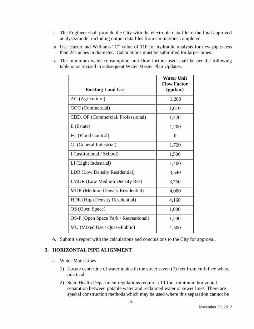
n. The minimum water consumption unit flow factors used shall be per the following
table or as revised in subsequent Water Master Plan Updates:
o. Submit a report with the calculations and conclusions to the City for approval.
3. HORIZONTAL PIPE ALIGNMENT
a. Water Main Lines
1) Locate centerline of water mains in the street seven (7) feet from curb face where
practical.
2) State Health Department regulations require a 10-foot minimum horizontal
separation between potable water and reclaimed water or sewer lines. There are
special construction methods which may be used where this separation cannot be
Existing Land Use
Water Unit
Flow Factor
(gpd/ac)
AG (Agriculture) 1,200
GCC (Commercial) 1,610
CBD, OP (Commercial/ Professional) 1,720
E (Estate) 1,200
FC (Flood Control) 0
GI (General Industrial) 1,720
I (Institutional / School) 1,500
LI (Light Industrial) 1,400
LDR (Low Density Residential) 3,540
LMDR (Low Medium Density Res) 3,750
MDR (Medium Density Residential) 4,000
HDR (High Density Residential) 4,160
OS (Open Space) 1,000
OS-P (Open Space Park / Recreational) 1,200
MU (Mixed Use / Quasi-Public) 1,500
-6- November 29, 2012
achieved. Refer to the City Standard Drawing 419 for additional information.
Separation other than the Health Department minimums must be approved by the
District Engineer or State Health Department.
3) Provide minimum three (3) feet horizontal separation clearance (edge of pipe to
edge of existing utility) with other utilities.
4) Pipe joint deflection angle not to exceed 80% of the manufacturer's
recommendations, and never more than two degrees. Pipe joint deflections shall
not occur where the pipeline crosses another utility.
b. Water Services
1) Must clear driveway.
2) Ten (10) feet clear separation with sanitary sewer and non-potable water laterals.
3) For condominium and apartment buildings, please provide a detailed plan to the
Department of Water and Power for the location of all individual water services.
4) Services shall not be connected to fire lines, hydrant laterals, transmission lines,
and pipes greater than 12 inches in diameter.
4. VERTICAL PIPE ALIGNMENT
a. Eight (8)-inch water line to have minimum thirty-six (36) inches of cover. Twelve
(12)-inch and larger water lines shall have a minimum forty-two (42) inches of cover.
b. Water, sewer, and reclaimed water lines are typically located vertically from the street
surface down in order of decreasing quality. Water will be the shallowest and sewer
mains will be the deepest. Provide minimum of 12 inches vertical clearance at utility
crossings. Refer to the City Standard Drawings for additional information.
c. One (1)-foot minimum clear separation between potable water lines and sanitary
sewer and non-potable waterlines with potable water pipe on top. All crossings must
conform to CDPH separation standards for utilities.
d. Twelve (12)-inch sand blanket separation with other utilities.
e. A minimum six (6)-inch fire hydrant blow-off is required at all sags. The Design
Engineer shall identify larger blow-offs where required.
f. A minimum 1-inch air vacuum relief valve is required at all summits. The Design
Engineer shall identify larger valves as required.
g. Sizing and spacing of blow-offs and air/vacs shall be per the manufacturer’s written
recommendations. Water velocities in the main line shall not exceed five (5) feet per
second (in draining condition) and a reach of main line pipe shall be able to be
drained in less than four (4) hours. Submit calculations signed by a Registered Civil
Engineer with catalog cut sheets of the proposed devices with plans.
h. Show waterlines larger than eight (8) inches in diameter in plan and profile.
i. Show eight (8) inch waterlines in a detailed profile where crossing other underground
facilities, utilities, sewers, storm drains, etc.
-7- November 29, 2012
5. WATER SERVICE
Separate water service is required for each building:
a. Residential: 1-inch minimum
b. Commercial: 2-inch minimum
c. Industrial: 2-inch minimum
In the case of condominiums and apartments, each dwelling unit is required to have its
own separate water service.
6. PIPELINE SIZING
a. Mainline sizes shall be 8-inch, 12-inch, 16-inch, 20-inch and 24-inch. Pipes greater
than 24-inch shall be increased by 6-inch increments (30-inch, 36-inch, 42-inch, etc.)
No other sizes will be accepted unless approved by the Department of Water and
Power.
b. Minimum pipeline sizes shall be:
1) Eight-inch where required fire flows are less than or equal to 1,500 gpm.
2) Twelve-inch where required fire flows are greater than 1,500 gpm.
3) Exception in sizing may be approved for loop conditions where velocities are less
than 15 fps for fire flow and max day flow as demonstrated by hydraulic
modeling.
c. Commercial, industrial, multifamily projects shall include a 12-inch backbone
pipeline through or on the project boundary streets if one does not currently exist.
7. FIRE HYDRANTS
a. Space fire hydrants every 250 feet (maximum spacing) unless otherwise approved by
the City of Corona Fire Department. Connect fire hydrants to dead ends to serve as a
blow-off function. Minor adjustments in spacing may be permitted to allow a fire
hydrant to act as blow-off for sags in pipeline alignments.
b. Hydrant runs (hydrant to tee shall not exceed 100 feet).
c. Fire hydrants shall be installed on the same side of the street centerline as the water
main is installed unless otherwise directed by the Fire Department.
8. VALVES AND VALVE LAYOUT - CRITERIA
a. Resilient wedge gate valves shall be called out on the plans for pressures less than
250 psi.
b. Butterfly valves may be used provided the Design Engineer obtains prior written
approval from the Department of Water and Power, Operations.
c. The maximum distance between main line valves on pipelines shall be 1,000 feet.
Reaches shall be able to be drained completely in less than 4 hours.
-8- November 29, 2012
d. Minimum number of valves at a tee (except for fire hydrants and fire lines) shall be
three, and four at a cross.
e. Where possible, valves shall be arranged, so that no more than two fire hydrants will
be shut off at one time when a waterline is shut down for repairs.
f. Configure blow-offs per the City of Corona Standard Detail 416.
9. PRIVATE FIRE SERVICE CONNECTIONS
Double check detector assemblies are required on all private fire service connections. The
assembly shall be above ground and located behind the parkway within a landscaped area
and within a dedicated easement to the City of Corona. The piping and valving shall be in
conformance with City Standard Plan 417.
10. PIPE MATERIAL
a. Fully restrain all pipelines.
b. Ductile Iron, cement mortar lined and encased with two sheets of 8-mil polyethylene
encasement, color blue; pressure or thickness class of pipe to be determined by the
Design Engineer, (minimum working pressure of 150 psi). Pipes less than 12-inches
in diameter shall be Pressure Class 350, or Equivalent Thickness Class (minimum).
c. Steel, cement mortar lined and cement coated, with welded joints may be used after
written approval of Department of Water and Power. The pipeline shall be
constructed under observation by full-time certified welding inspectors.
d. Unless a detailed surge analysis is completed by the design engineer (and accepted by
City of Corona, Department of Water and Power), surge (in psi) shall be based on the
following formula: Surge (psi) = 50 x (pipeline velocity in fps).
11. IDENTIFICATION MARKINGS
a. Paint all air/vacuum assemblies, valves, pressure reducing valves, pumps, pump
control valves, meter box lids, meter box interiors, and any other appurtenances to the
potable water system per the DWP Standard Details for Potable Water Construction.
b. Install 6-inch identification tapes with black printing on blue field containing the
words “POTABLE WATER” over the pipelines longitudinally 12 inches above the
top of pipe and centered over the pipeline. Secure the tape during the trench back fill.
All pipe shall be in a “blue” polyethylene encasement.
12. DEAD-END WATERLINES
No dead-end waterlines or stub-outs for future development are allowed, except with
prior written approval from the Department of Water and Power. If approved, dead-end
waterlines shall be provided with a means of flushing the waterlines, such as, fire
hydrants or blow-off so that flushing velocities in the water main will be attained (3 feet
per second, minimum). Dead-end waterlines may require a larger size to meet maximum
velocity criteria outlined above.
-9- November 29, 2012
13. EASEMENTS
a. Waterlines shall be located in public roads where they can be maintained. In all other
cases, an easement with all-weather access for pipelines and valves shall be shown on
Tract Maps, Parcel Maps, or a separate legal description for projects not subdividing
land.
b. When a separate instrument is required, prepare a legal description with an 8-1/2" x
11" exhibit showing the location of said easement.
c. Private water systems are not allowed to cross adjacent/adjoining private parcels/land
without specific approval from the DWP.
d. Easements shall be 20 feet wide. The minimum distance between any structure and
water line shall be ten feet.
e. Easements are required for fire services including a detector check.
f. All legal easement descriptions and exhibits shall be prepared and stamped by a
Registered Civil Engineer licensed in the State of California or Professional Land
Surveyor licensed in the State of California and filed with the County Recorder if not
shown on a tract or parcel map. Professional licenses must be current at the time of
plan preparation.
14. CORROSIVE SOIL
a. All pipeline designs shall require a geotechnical engineer to determine the existing
soil corrosivity and the design engineer to recommend the appropriate cathodic
protection facilities. The engineer shall specify on the plans and in the specifications
the applicable corrosion control facilities.
b. All ductile iron pipe and copper service lines shall have at a minimum two 8-mil
polyethylene protective sleeves color coded to match the contents of the pipe. Clearly
denote this on each plan sheet.
c. All ductile iron pipelines crossing railroad facilities, large natural gas pipelines, or
electrical facilities having impressed currents shall be provided with cathodic
protection facilities.
d. All ductile iron transmission lines shall have cathodic test stations per DWP Standard
Details 450 through 458. Clearly denote this on each plan sheet.
15. SPECIAL CROSSINGS
a. Coordinate all pipeline crossings with the following agencies, as applicable.
a. State Highways : Caltrans
b. Flood Control: City of Corona and Riverside County Flood Control District
c. Utilities: Utility companies with permitting requirements for crossing
b. The design engineer shall verify the permit requirements and follow the procedure for
submitting the crossing details with the related agency and the City of Corona.
-10- November 29, 2012
c. All pipelines in steel casings shall have cathodic test stations per DWP Standard
Details 450 through 458. The design shall be inclusive of quantity, location and size
of anodes installed and shall be per the recommendations of a corrosion control
expert. The corrosion control expert shall also recommend whether or not the system
shall be passive or active.
16. PIPELINE SEPARATIONS
Provide the minimum separation required between potable water line, reclaimed water
line, and sewer line in accordance with the California Code of Regulations, Title 22 and
the City of Corona Standard Detail 419.
17. METER BOXES
a. Water meters shall be located in the public right-of-way or in an adequate easement.
Do not locate new water services inside parking areas or driveways except where the
service already exists, or sufficient area is not available outside of driveways to locate
the service. The water meter boxes shall be constructed in accordance with the City of
Corona Standard Details 408, 409, 414, and 415.
b. If the water service is located within an area subject to traffic loads, the meter box and
lid will be designed to handle H20 loadings
18. BACKFLOW PREVENTION DEVICES
Back flow prevention devices shall be installed on all dedicated fire flow systems,
irrigation systems, existing or future reclaimed water systems, and where required by the
Department of Water and Power. Backflow prevention devices shall comply with
AWWA C511 and shall be IAPMO listed, FM approved, UL classified, and approved by
the Foundation for Cross Connection Control and Hydraulic Research at the University of
Southern California. Obtain “Appendix B” Approved Backflow Prevention Devices for
Service Isolation” from the City of Corona – Department of Water and Power or the
latest list of approved backflow prevention devices from the California Department of
Public Health. Installation shall comply with the City of Corona Standard Detail 428.
19. HOT TAPS
a. All hot taps shall be approved by the Department of Water and Power, Operations.
Tapping operation shall be performed by an experienced crew. All hot taps 12 inches
and larger shall be performed by either Koppl Company located in Montebello,
California or International Flow Technologies, Inc. located in Murrieta, California or
as otherwise approved. Tapping crew shall have more than five (5) years’ experience
in tapping connections, including at least three (3) installations of same size and
complexity as the proposed tapping, and shall provide a reference listing showing
facilities owner’s name, location, telephone number, contact person, size and material
of existing pipe and size of tapping.
b. All new hot tap connections shall be no greater than 67 percent of the main line pipe
size.
-11- November 29, 2012
20. PIPE TRENCH BACKFILL
a) All pipeline trench backfill within paved areas shall meet the requirements of
Public Works Standard Detail 150.
b) All pipeline trench backfill with landscaped parkway areas shall meet the
requirements of Public Works Standard Detail 149.
c) All pipeline bedding shall meet the requirements of Department of Water and
Power Standard Detail 406.
21. ADJACENT SEWER LINE INSPECTION
a. All waterline projects in streets with sewer laterals shall have the sewer laterals
cleaned and inspected via CCTV by Roto Rooter (no substitutes). The sewer lateral
cleaning and CCTV inspections shall include the portion between the dwellings and
the sewer main. The cleaning and CCTV inspections shall be conducted after the
waterline has been constructed, but before paving operations. All needed repairs
within the public right-of-way shall be made by the pipeline contractor as a change
order. Final CCTV inspections shall be made after repair(s) have been completed to
confirm the integrity of the repair(s).
b. All waterline projects shall have the adjacent sewer main line and corresponding
manholes cleaned and inspected via CCTV during the preliminary design phase. All
needed repairs to the sewers and/or manholes shall be addressed within the contract
documents prior to bidding.
c. Cleaning and CCTV inspection of sewers and manholes and corresponding repairs
shall be completed and compensated for in accordance with Part 5- System
Rehabilitation of the Standard Specifications for Public Work Construction (latest
Edition of “Green Book”).
-12- November 29, 2012
C. WATER RECLAMATION (SEWER) COLLECTION SYSTEM
1. GENERAL
The following sections provide criteria to be used in the design of water reclamation
collection (sewer) systems. The developer and his engineer shall be responsible to ensure
all design work is in conformance with this Design Policy, the City of Corona Standard
Plans and Specifications for sewer systems, State of California Department of Health
Services Criteria for the Separation of Water Mains and Sanitary Sewers, as shown on
City Standard Drawings 419, and generally accepted standards of good engineering
practice. Two sets of calculations are required with first plan check.
2. PIPELINE DESIGN CRITERIA
a. Velocity - Design Engineer shall calculate the velocity of flow under proposed
conditions. Velocity shall not be less than 2 fps a minimum of once per day to
provide sufficient scouring action for self-cleaning. Maximum velocity shall not be
greater than 8 fps at design flow. Where 2 fps velocity cannot be provided at least
once per day, the slope shall be at least 0.01 ft/ft unless approved in writing by DWP.
b. Use a Manning's "n" of 0. 013 for sewer design.
c. Maximum allowable depth of flow (d/D) at peak flows, is as follows:
1) 10-inch and smaller 50 percent
2) 12-inch and larger 67 percent
d. For more information refer to the engineering report in the Sewer Master Plan for
Trunk Line Sewers.
e. Minimum slope(s) shall be:
S = 0.0040 for 8-inch sewer
S = 0.0025 for 10-inch sewer
S = 0.0020 for 12-inch sewer
S = 0.0012 for 15-inch sewer
S = 0.0010 for 18-inch sewer
S = 0.0008 for 21-inch sewer
S = 0.0007 for 24-inch sewer
Design slopes conforming to the minimum and maximum velocity criteria described
in section 2(a) above.
The design engineer shall submit calculation including the slopes for each segment of
the pipeline. Sewer slope shall not be changed in the field unless approved by the
DWP District Engineer as it could negatively impact future capacity.
f. Manholes are required at grade breaks.
-13- November 29, 2012
g. Provide 0.10-foot drop of invert elevation through manholes. Provide 0.20-foot drop
of invert elevation at right angle alignment or bends.
h. Minimum 12-inch vertical separation is required when a sewer line crosses
water/reclaimed water lines. Encase the sewer line in concrete in accordance with the
City of Corona Standard Detail 419.
i. If separation with a parallel water main is less than 10 feet clear (edge-to-edge),
design must meet requirements of City Standard Drawings 419 and be reviewed and
approved by CDPH or DWP.
j. A minimum of 1-foot vertical separation is required between potable waterlines and
both non-potable waterlines and sewer lines. The potable waterline must be above
the non-potable waterlines and sewer lines. Separation criteria must follow current
CDPH requirements.
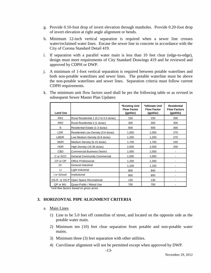
k. The minimum unit flow factors used shall be per the following table or as revised in
subsequent Sewer Master Plan Updates:
3. HORIZONTAL PIPE ALIGNMENT CRITERIA
a. Main Lines
1) Line to be 5.0 feet off centerline of street, and located on the opposite side as the
potable water main.
2) Minimum ten (10) feet clear separation from potable and non-potable water
mains.
3) Minimum three (3) feet separation with other utilities.
4) Curvilinear alignment will not be permitted except when approved by DWP.
Land Use
*Existing Unit
Flow Factor
(gpd/ac)
*Ultimate Unit
Flow Factor
(gpd/ac)
Residential
Flow Factors
(gpd/du)
RR1 Rural Residential 1 (0.2 to 0.5 du/ac) 150 150 300
RR2 Rural Residential 2 (1 du/ac) 300 300 300
E Residential Estate (1-3 du/ac) 500 500 300
LDR Residential Low Density (3-6 du/ac) 1,000 1,000 270
LMDR Low Medium Density (6-8 du/ac) 1,200 1,200 270
MDR Medium Density (6-15 du/ac) 1,700 1,700 240
HDR High Density (15-36 du/ac) 2,000 2,000 200
CBD Commercial Business District 1,000 1,050 -
C or GCC General Community Commercial 1,000 1,050 -
CP or OP Office Professional 1,200 1,260 -
GI General Industrial 1,100 1,155 -
LI Light Industrial 800 840 -
I or School Institutional 800 800 -
OS-R or OS-P Open Space Recreational 130 130 -
QP or MU Quasi-Public / Mixed Use 700 700 -
*Unit flow factors based on gross acres
-14- November 29, 2012
5) Manholes are required at all change of directions, both horizontal and vertical,
and at 350-foot maximum spacing.
6) Clean-outs shall not be permitted except when approved by DWP.
7) Private sewer mains shall have a manhole spacing every 350 feet.
b. Sewer Laterals
1) Must clear driveway and be provided with clean-out.
2) Ten (10) feet clear separation with waterlines and water services unless otherwise
approved by DWP.
4. VERTICAL PIPE ALIGNMENT CRITERIA
a. Main Lines
1) Minimum depth shall be 7.0 feet of cover over the top of the pipe, except terminal
reaches may be reduced to 6.0 feet of cover, where the line will not be extended in
the future.
2) Vertical curve may be permitted – prior written approval from DWP is required.
b. Sewer Laterals
1) Minimum 5.0-foot cover at property line, minimum slope S = 0.02 with a saddle
unless otherwise approved.
2) Laterals shall be located below the water main with a minimum clearance of 12
inches. Where clearances are critical lateral profiles are to be detailed on the
plans.
3) Laterals shall not enter a manhole.
4) A backwater sewer valve shall be installed in an inspection vault, in conformance
with the plumbing code, for all buildings where the rim elevation of the upstream
manhole on the sewer main is above the pad elevation of the structure.
5. SANITARY SEWER MANHOLES
a. Pre-cast concrete manholes shall be constructed and lined with polyurethane (Sancon
100TM
or equal) per City Standard Drawing 302.
b. Manholes shall be 5-foot in diameter with 3-foot frame and cover for depths up to 12
feet from finish grade to sewer invert. Manholes deeper than 12 feet shall be 6-foot
diameter.
c. On the center of each manhole cover, lettering shall be cast to read “CITY OF
CORONA - SEWER.” This lettering shall be cast into the lid.
d. Manhole rim elevations shall be lower than all pad elevations immediately
downstream. If this condition cannot be met, then back water valves must be installed
in accordance with the Uniform Plumbing Code, Section 710.1. A letter with the tract
-15- November 29, 2012
number and affected lots shall be prepared by the Design Engineer and submitted to
the contractor/developer/owner with a copy to the Building Inspector, the Building
Department, the Department of Public Works and the Department of Water and
Power. Identify these lots on the grading and plumbing plans.
e. Manholes located in undeveloped land shall be surrounded by a 10-foot by 10-foot by
6-inch concrete pad reinforced with 6x6 10/10 WWF (minimum), marked with a 4-
inch pipe embedded in concrete 2 feet below existing ground and 4 feet above
existing ground. Manholes located in improved areas shall be located by chipping
1½-inch lettering in the curb face “MH” with dimensions to the manhole from a
minimum of 2 ties points.
f. No stub-outs allowed on manholes, except where future connections are anticipated.
6. DROP MANHOLES
Drop manholes are not allowed except when specifically approved by the Department of
Water and Power General Manager. If approved, the design shall be in accordance with
the City of Corona Standard Detail 303.
7. PIPE MATERIAL AND SIZE
a. Main Lines
1) Main line minimum size shall be 8 inches.
2) Use SDR 26 PVC green pipe for all residential developments.
3) Use extra-strength Vitrified Clay Pipe (VCP) for all commercial and industrial
developments.
4) Use ductile iron pipe with Protecto 401 TM
lining and two sheets of 8-mil
polyethylene encasement, color green, where construction constraints, such as
clearances with waterlines or excessive loading condition (depth of cover greater
than 15 feet), warrant their use.
5) Construct all pipelines of the same material between manholes.
b. Laterals
1) Lateral minimum size for residences shall be 4 inches. Lateral minimum size for
commercial and industrial units shall be 6 inches.
2) Use green PVC pipe, SDR 21, CERTA LOK TM
restrained joints for residential
laterals. Call out pipe material, wall thickness, and joint style on the plans.
3) Use extra-strength vitrified clay pipe for all commercial and industrial laterals.
4) Laterals shall not be connected/manifolded together. Every individual building
shall be connected to a public sewer line by a single sewer lateral. Multiple
buildings on same property must have separate laterals connecting to the public
sewer.
-16- November 29, 2012
5) Use ductile iron pipe where separation criteria with water mains (i.e., clearances)
cannot be met per CDPH separation requirements.
8. CORROSIVE SOIL
a. All pipeline designs shall require a geotechnical engineer to determine the existing soil
corrosivity and the design engineer to recommend the appropriate cathodic protection
facilities. The engineer shall specify on the plans and in the specifications the applicable
corrosion control facilities.
b. All ductile iron pipes shall have at a minimum two 8-mil polyethylene protective sleeves
color coded to match the contents of the pipe. Clearly denote this on each plan sheet.
c. All ductile iron pipelines crossing railroad facilities, large natural gas pipelines, or
electrical facilities having impressed currents shall be provided with cathodic protection
facilities.
d. All ductile iron transmission lines shall have cathodic test stations per DWP Standard
Details 450 through 458. Clearly denote this on each plan sheet.
9. EASEMENTS
Where public sanitary sewers cannot be located in public roads, they shall be constructed in a
prescribed easement to meet the following conditions:
a. A separate instrument is required if the easement is not shown on the Tract or Parcel
Map. The instrument includes a legal description and exhibit 8½" x 11" showing the
location of said easement. Private sewers are not allowed to cross adjacent/adjoining
private parcels/land without special approval from DWP.
b. The easement shall be a minimum of 20 feet wide. Easements shall contain an all-
weather access road in order to maintain the entire sewer system (pipeline, manholes,
lift station, etc.) within the easement.
c. Easements for deep sewers shall be wide enough for sewer maintenance. The
minimum width of easement shall be wide enough to accommodate a maximum of
1:1 side slopes, with a 5-foot wide by 10-foot maximum depth trench shield, and an
additional 10-foot wide truck access road.
d. All legal easement descriptions and exhibits shall be prepared and stamped by a
Registered Civil Engineer licensed in the State of California or Professional Land
Surveyor licensed in the State of California and filed with the County Recorder if not
shown on a tract or parcel map. Professional licenses must be current at the time of
plan preparation.
10. LIFT STATION DESIGN CRITERIA
Avoid the use of lift stations wherever possible due to the associated cost and
maintenance required. Design Engineer shall utilize the following minimum sewer lift
station design guidelines.
-17- November 29, 2012
a. Design the wet well with sufficient capacity to prevent short cycles whereby the
pumps frequently start and stop, yet small enough that it will regularly evacuate
sewage from the wet well to prevent the wastewater from becoming septic. The
desired number of pump cycles should be limited to no more than 6 per hour for
motors up to 10 horsepower. Motors up to 75 horsepower should start no more than 4
times per hour. Larger motors should cycle less frequently. Lift stations should have
sufficient volume to store sewage in the event of mechanical or electrical failures,
until the City can respond to the failure and prevent overflows.
b. Size the pumps to efficiently handle the peak wet weather flows. Provide a minimum
of two pumps sized at the peak wet weather flow to the station, so that sufficient
standby capacity is available when one pump is removed for repairs or experiences a
mechanical failure. Select pumps capable of passing a minimum solid size of 3-inches
without clogging. Select pumps with shafts, seals and impellers constructed of wear
resistant material to provide long life. Provide Tungsten Carbide seals, Ni-Hard
impellers, and 316 stainless steel pump shafts. For services where aggressive agents
may be found in the sewage, such as at golf courses, select pumps with complete
stainless steel construction, including the pump bowl, shaft, impeller, and motor
housing.
c. Dry well lift stations must be properly ventilated and provide unobstructed access to
all equipment. A minimum 3-foot clearance from all obstructions should be
provided. Greater clearances may be required for equipment with special
maintenance needs. Provisions for equipment removal including hatches, large door
openings, and hoists shall also be provided.
d. Install discharge piping, valves, and equipment at submersible pump installations
above grade.
11. FORCEMAINS
Force main Systems shall be of adequate size to efficiently transmit the total ultimate
peak operational flows supplied by the connected wastewater pumping station(s), to the
discharge point. Coordinate capacity computations with the proposed pumping
system(s), along with any future flow requirement, if applicable. In order to provide
adequate pipeline cleansing, force main flow velocity shall not be less than four (4) feet
per second at the minimum pumping capacity nor exceed six (6) feet per second at
ultimate design pumping capacity. The force main diameter, material, coating, pressure
class/thickness class, etc. shall be as required by the City Standard Details, City Design
Policy, and the design engineer. Provide signed and sealed calculations to substantiate
the force main diameter. Design a redundant force main or a gravity bypass line if
physically possible.
Other features, provisions, and operational procedures for these systems include:
a. Auto flushing connection with an approved backflow preventer and air gap.
b. The force main shall be flushed once per month with a minimum of 1½ force main
volumes.
-18- November 29, 2012
c. Emergency shutdown provisions to mitigate sewer spills/overflows.
d. Contractor/Engineer/Private Owner shall submit an operations and maintenance
procedure complete with calculations.
e. Pipe shall be Ductile Iron Pipe with Protecto 401 TM
epoxy lining and wrapped with
green-colored polyethylene encasement. 4-inch minimum pipe size.
f. Provide combination sewage and air vacuum valve assemblies at high points.
12. INVERTED SIPHONS
Avoid inverted sewer siphons wherever possible. If required, utilize the following
minimum design guidelines.
a. Locate the inverted siphon completely within a public right-of-way. If a location
within public right-of-way is unavailable, an easement or other right-of-entry is
required subject to approval by the Department of Water and Power.
b. The inverted siphon shall not impact other facilities or be impacted by other facilities.
Maintain adequate clearances from other facilities.
c. Provide a minimum of two barrels. Always provide one redundant barrel for by-pass
capacity, emergencies, and maintenance purposes.
d. Minimum pipe size of 6-inch and minimum velocity of 3 ft/sec shall be considered
for design of each barrel.
e. Minimize bends and angle points.
f. Provide cleanouts where the length of inverted siphon exceeds 400-ft. The size of the
cleanout shall be adequate to handle the debris that may accumulate, and at least as
large as the size of the inverted siphon.
13. PIPE TRENCH BACKFILL
a) All pipeline trench backfill within paved areas shall be per Public Works Standard
150.
b) All pipeline trench backfill within landscaped parkway areas shall be per Public
Works Standard 149
c) All pipeline bedding shall be per Department of Water and Power Standard 308.
-19- November 29, 2012
D. LOW PRESSURE SEWER SYSTEMS
1. GENERAL PROVISIONS
a. Submit plans and specifications for low-pressure sewer systems to the Department of
Water and Power for review and approval. Secure a permit for each low-pressure
sewer installation. Approval of low-pressure wastewater systems as an alternative to
conventional wastewater systems shall be in accordance with the conditions listed in
Subsection 2 unless other special circumstances justifying their use are affirmatively
demonstrated.
b. It is not the intent of this design policy to utilize low-pressure systems as a
replacement for conventional gravity sewer systems. However, as a means to provide
service to an individual lot or a small group of lots or buildings where conventional
gravity service cannot be utilized within reason, the Department of Water and Power
may consider the use of a low-pressure system; providing the Design Engineer can
show reasonable justification for its use.
2. CONDITIONS OF APPROVAL
a. The use of low-pressure sewer systems will be considered where:
1) build-out has left small parcels of property in precarious locations in relation to
the lay of the land,
2) shallow bedrock conditions would require extensive rock removal,
3) unstable soil conditions prohibit construction of deep sewers,
4) temporary use would provide a cost effective alternative until gravity system
construction is completed,
5) the proposed sewer is located a considerable distance from existing gravity
sewers, or
6) the use of a low-pressure sewer system will eliminate the need for small public lift
stations.
b. The applicant is responsible to evaluate all potential alternative wastewater collection
systems and justify the selection of the low-pressure sewer system based on
engineering and surrounding conditions.
c. Based on the information furnished by the Developer and the Design Engineer, the
Department of Water and Power will decide the acceptability, scope and extent of the
low pressure sewer system to be permitted.
-20- November 29, 2012
E. RECLAIMED WATER DISTRIBUTION SYSTEM
1. GENERAL
The following sections provide criteria to be used in the design of potable water systems.
The developer and his engineer shall be responsible to ensure all design work is in
conformance with this Design Policy, the City of Corona Standard Plans and Specifications
for Reclaimed Water Systems, California Water Works Standards, Title 22 of the California
Administrative Code, the Criteria for the Separation of Water Mains and Sanitary Sewers as
approved by the Department of Health Services, Sanitary Engineering Section, and generally
accepted standards of good engineering practice. Two sets of calculations are required with
first plan check.
2. SUPPORTING CALCULATIONS – CRITERIA
a. Calculations shall be made on standard 8 ½ inch x 11 inch sheets and must be signed
by a registered Civil Engineer licensed in the State of California.
b. The Engineer shall prepare hydraulic calculations to demonstrate that the reclaimed
water system is capable of delivering the required flow at acceptable velocities and
pressures per Design Criteria provided below.
c. The Average Day Demand shall be determined based on reclaimed water meter
records or minimum 4,500 gpd / ac for landscaped areas, or 5 ac-ft / yr per acre.
d. The Maximum Day Demand shall be equal to four (4) times Average Day Demand
(minimum).
e. Peak Hour Demand shall be equal to eight (8) times Average Day Demand
(minimum).
f. Design distribution mains and on-site irrigations systems to meet the peak hour
demands.
g. The maximum design velocity in the distribution main or on-site irrigation system
during peak hour demands shall not exceed seven (7) feet per second (fps).
h. Prepare design calculations (distribution main pipe friction including minor head
losses) using C = 110 in Hazen Williams equation for distribution mains.
i. Use Hardy Cross or other suitable method in a looped system to determine the
pressures at critical locations. Computer Programs are acceptable.
j. Minimum 80 psi dynamic pressure during Average Day Demands and 60 psi dynamic
pressure during Maximums Day Demand are acceptable.
k. Prior to initiation of service, perform a pressure test or visual inspection of the
pipeline in open trenches to ensure there are no cross connections with potable water
system.
l. To add water from potable water system to non-potable water system an air gap is
required.
-21- November 29, 2012
m. Irrigate between 10 p.m. and 6 a.m., or alternative schedule as established by
coordinating with the DWP.
n. Submit a report with calculations and conclusions to the DWP for approval.
3. HORIZONTAL PIPE ALIGNMENT
a. Locate centerline of reclaimed water mains in the street seven (7) feet from the curb
face where practical, and on the opposite side of the street from potable waterlines.
b. State Health Department regulations require a 10-foot minimum horizontal separation
between reclaimed water and potable water or sewer lines. There are special
construction methods which may be used where this separation cannot be achieved.
Refer to the City Standard Drawing 419 for additional information. Separation other
than the Health Department minimums must be approved by the District Engineer or
State Health Department.
c. Provide minimum three (3) feet horizontal separation clearance (edge of pipe to edge
of existing utility) with other utilities.
d. Pipe joint deflection angle not to exceed 80% of the manufacturer's
recommendations, and never more than two degrees. Pipe joint deflections shall not
occur where the pipeline crosses another utility.
4. VERTICAL PIPE ALIGNMENT CRITERIA
a. Pipe to have minimum fifty-four (54) inches of cover.
b. One (1) foot minimum separation between reclaimed water line and sanitary sewer
lines and/or potable water lines. All crossings must conform to CDPH separation
standards for utilities.
c. Twelve (12) inch sand blanket separation with other utilities.
d. A minimum 6-inch fire hydrant blow-off is required at all sags. The Design Engineer
shall identify larger blow-offs where required.
e. A minimum 1-inch air vacuum relief valve is required at all summits. The Design
Engineer shall identify larger valves if required.
f. Sizing and spacing of blow-offs and air/vacs shall be per the manufacturer’s written
recommendations. Water velocities in the main line shall not exceed five (5) feet per
second (in draining condition) and reach of main line pipe shall be able to be drained
in less than four (4) hours. Calculations signed by Registered Civil Engineer with
catalog cut sheets of the proposed devices shall be submitted with plans.
g. Show water lines larger than 8-inches in diameter in plan and profile.
h. Show eight (8) inch and larger water lines in a detail profile where crossing other
underground facilities, utilities, sewers, potable water, storm drains, etc.
5. RECLAIMED WATER SERVICES AND METERS
a. Must clear drive way.
-22- November 29, 2012
b. Reclaimed water lines 1 ½ inches and less in diameter below grade shall be buried
with a cover of at least 18 inches.
c. Ten (10) feet clear separation with sanitary sewer and potable water laterals.
d. Reclaimed water and spray shall be confined to the authorized use area.
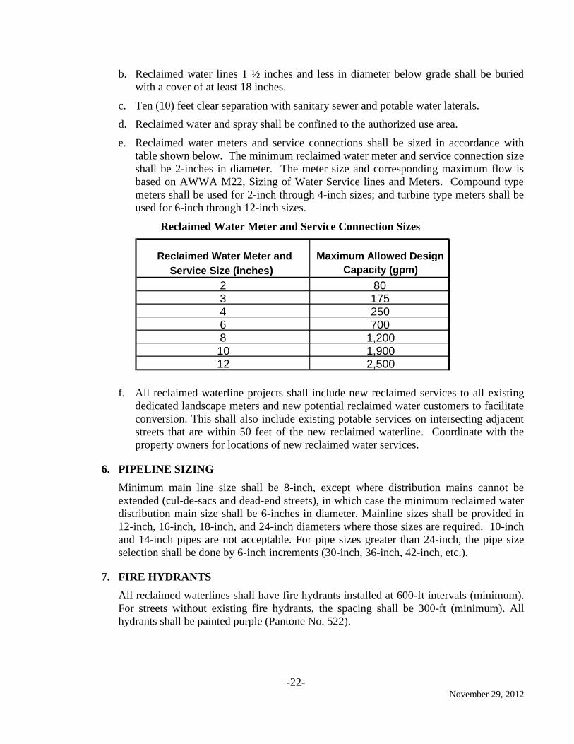
e. Reclaimed water meters and service connections shall be sized in accordance with
table shown below. The minimum reclaimed water meter and service connection size
shall be 2-inches in diameter. The meter size and corresponding maximum flow is
based on AWWA M22, Sizing of Water Service lines and Meters. Compound type
meters shall be used for 2-inch through 4-inch sizes; and turbine type meters shall be
used for 6-inch through 12-inch sizes.
Reclaimed Water Meter and Service Connection Sizes
f. All reclaimed waterline projects shall include new reclaimed services to all existing
dedicated landscape meters and new potential reclaimed water customers to facilitate
conversion. This shall also include existing potable services on intersecting adjacent
streets that are within 50 feet of the new reclaimed waterline. Coordinate with the
property owners for locations of new reclaimed water services.
6. PIPELINE SIZING
Minimum main line size shall be 8-inch, except where distribution mains cannot be
extended (cul-de-sacs and dead-end streets), in which case the minimum reclaimed water
distribution main size shall be 6-inches in diameter. Mainline sizes shall be provided in
12-inch, 16-inch, 18-inch, and 24-inch diameters where those sizes are required. 10-inch
and 14-inch pipes are not acceptable. For pipe sizes greater than 24-inch, the pipe size
selection shall be done by 6-inch increments (30-inch, 36-inch, 42-inch, etc.).
7. FIRE HYDRANTS
All reclaimed waterlines shall have fire hydrants installed at 600-ft intervals (minimum).
For streets without existing fire hydrants, the spacing shall be 300-ft (minimum). All
hydrants shall be painted purple (Pantone No. 522).
Reclaimed Water Meter and
Service Size (inches)
Maximum Allowed Design
Capacity (gpm)
2 80
3 175
4 250
6 700
8 1,200
10 1,900
12 2,500
-23- November 29, 2012
8. VALVES AND VALVE LAYOUT – CRITERIA
a. Resilient wedge gate valves shall be called out on the plans for pressures less than
250 psi.
b. Butterfly valves may be used provided the design Engineer obtains prior written
approval from the Department of Water and Power, Operations.
c. Valves shall be installed on each branch of tees and crosses that provide the main
feed into the development.
d. Hose bibs are not allowed on reclaimed water piping.
e. Configure bow-offs per the City of Corona Standard Detail 416.
9. PIPE MATERIAL AND CLASS
a. Fully restrain all pipelines.
b. Ductile Iron, cement mortar lined and encased with two layers of 8-mil polyethylene
encasement, purple color.
c. Pressure Class of pipe to be determined by Design Engineer for the greater of the
following conditions:
1) Reclaimed water booster pump shut-off head
2) Reclaimed water Average Day Demand working pressure plus surge
3) Peak hour reclaimed water demand working pressure plus surge.
4) Pipe pressure class 350 (minimum) for pipes smaller than 12-inch in
diameter.
d. Unless a detailed surge analysis is completed by the design engineer (and accepted by
City of Corona, Department of Water and Power), surge (in psi) shall be based on the
following formula: Surge (psi) = 50 x (pipeline velocity in fps).
10. IDENTIFICATION MARKINGS
a. Paint all air/vacuum assemblies, valves, pressure reducing valves, pumps, pump
control valves, meter box lids, meter box interiors, and any other appurtenances to
the reclaimed water system purple (Pantone No. 522C) or have purple color integral
to the material.
b. Install 6-inch identification tape with black printing on purple field containing the
words “CAUTION: RECLAIMED WATER - DO NOT DRINK” and
“PELIGRO: AGUA IMPURA – NO BEBER” over the pipelines longitudinally 12
inches above the top of pipe and centered over the pipeline. Secure the tape during the
trench back fill. All pipe shall be “purple” color or in a “purple” polyethylene
encasement.
11. EASEMENTS
a. Reclaimed water lines shall be located in public roads where they can be maintained.
In all other cases, an easement with all-weather access for pipelines and valves shall
-24- November 29, 2012
be shown on Tract Maps, Parcel Maps, or a separate instrument will be required for
projects not subdividing land.
b. When a separate easement document is required, prepare a legal description with an 8
½” x 11” exhibit showing the location of said easement.
c. Private reclaimed water systems are not allowed to cross adjacent/adjoining private
parcels/land.
d. Easements shall be 20-ft wide. The minimum distance between any structure and
water line shall be 10-ft.
e. All legal easement descriptions and exhibits shall be prepared and stamped by a
Registered Civil Engineer licensed in the State of California or Professional Land
Surveyor licensed in the State of California and filed with the County Recorder if not
shown on a tract or parcel map. Professional licenses must be current at the time of
plan preparation.
12. CORROSIVE SOIL
a. All pipeline designs shall require a geotechnical engineer to determine the existing
soil corrosivity and the design engineer to recommend the appropriate cathodic
protection facilities. The engineer shall specify on the plans and in the specifications
the applicable corrosion control facilities.
b. All ductile iron pipe and copper service lines shall have at a minimum two 8-mil
polyethylene protective sleeves color coded to match the contents of the pipe. Clearly
denote this on each plan sheet.
c. All ductile iron pipelines crossing railroad facilities, large natural gas pipelines, or
electrical facilities having impressed currents shall be provided cathodic protection
facilities.
d. All ductile iron transmission lines shall have cathodic test stations per DWP Standard
Details 450 through 458. Clearly denote this on each plan sheet.
13. SPECIAL CROSSINGS
a. Coordinate all pipeline crossings with the following agencies, as applicable.
1) State Highways : Caltrans
2) Flood Control: City of Corona
3) Flood Control: Riverside County Flood Control District
4) Utilities: Utility companies with permitting requirements for crossing
b. The design engineer shall verify the permit requirements and follow the procedure for
submitting the crossing details with the related agency and the City of Corona.
c. All pipelines in steel casings shall have cathodic test stations per DWP Standard
Details 450 through 458. The design shall be inclusive of quantity, location and size
of anodes installed and shall be per the recommendations of a corrosion control
-25- November 29, 2012
expert. The corrosion control expert shall also recommend whether or not the system
shall be passive or active.
14. PIPELINE SEPARATIONS
Provide the minimum separation required between potable water line, reclaimed water
line, and sewer line in accordance with the California Code of Regulations, Title 22 and
the City of Corona Standard Detail 419.
15. METER BOXES
a. Reclaimed water meters shall be located in the public right-of-way or in an adequate
easement. Do not locate new reclaimed water services inside parking areas or
driveways except where the service already exists, or sufficient area is not available
outside of driveways to locate the service. The water meter boxes shall be constructed
in accordance with the City of Corona Standard Details 414R, and 415R.
b. If the reclaimed water service is located within an area subject to traffic loads, the
meter box and lid will be designed to handle H20 loadings.
16. HOT TAPS
a. All hot taps shall be approved by the Department of Water and Power, Operations.
Tapping operation shall be performed by an experienced crew. All hot taps 12 inches
and larger shall be performed by either Koppl Company located in Montebello,
California or International Flow Technologies, Inc. located in Murrieta, California or
as otherwise approved. Tapping crew shall have more than five (5) years’ experience
in tapping connections, including at least three (3) installations of same size and
complexity as the proposed tapping, and shall provide a reference listing showing
facilities owner’s name, location, telephone number, contact person, size and material
of existing pipe and size of tapping.
b. All new hot tap connections shall be no greater than 67 percent of the main line pipe
size.
17. PIPE TRENCH BACKFILL
a. All pipeline trench backfill within paved areas shall meet the requirements of Public
Works Standard 150.
b. All pipeline trench backfill with landscaped parkway areas shall meet the
requirements of Public Works Standard 149.
c. All pipeline bedding shall meet the requirements of Department of Water and Power
Standard 406.
18. ADJACENT SEWER LINE INSPECTION
a. All reclaimed waterline projects in streets with sewer laterals shall have the sewer
laterals cleaned and inspected via CCTV by Roto Rooter (no substitutes). The sewer
lateral cleaning and CCTV inspections shall include the portion between the
dwellings and the sewer main. The cleaning and CCTV inspections shall be
-26- November 29, 2012
conducted after the reclaimed waterline has been constructed, but before paving
operations. All needed repairs within the public right-of-way shall be made by the
pipeline contractor as a change order. Final CCTV inspections shall be made after
repair(s) have been completed to confirm the integrity of the repair(s).
b. All reclaimed waterline projects shall have the adjacent sewer main line and
corresponding manholes cleaned and inspected via CCTV during the preliminary
design phase. All needed repairs to the sewers and/or manholes shall be addressed
within the contract documents prior to bidding.
c. Cleaning and CCTV inspection of sewers and manholes and corresponding repairs
shall be completed and compensated for in accordance with Part 5- System
Rehabilitation of the Standard Specifications for Public Work Construction (latest
Edition of “Green Book”).
-27- November 29, 2012
F. TRENCHLESS CONSTRUCTION
1. GENERAL
a. Trenchless technology construction methods may be required for special crossings
and for special conditions. Examples of these special cases include, but are not
limited to, the following:
1) Depth of pipeline is excessive due to particular site conditions, making
conventional excavation uneconomical when considering materials handling and
shoring requirements.
2) Environmental conditions such as riparian habitat at stream crossings do not
permit conventional construction.
3) Disturbance caused by conventional construction to suburban, urban, or business
community is not permissible.
4) Congested intersections where from traffic or a utility standpoint, costly utility
relocation, utility support/underpinning, or traffic control can be avoided.
b. Because of increased urbanization, utility networks are growing in size and
complexity. As these networks grow, the need for special crossings by trenchless
construction methods is becoming more popular due to their inherent advantages.
Trenchless excavation construction methods may be divided into three basic
categories, pipe jacking, conventional tunneling, and horizontal boring.
c. Trenchless construction methods direct costs are more expensive than conventional
cut and cover pipe construction. However, social costs, environmental impact, and
other indirect costs due to noise, dust, losses of business, parking revenues, traffic
delays, etc. often make trenchless excavation competitive. Also, problems with
settlement, deep shoring, and utility relocation or support are avoided. Nevertheless,
the DESIGN CONSULTANT may take advantage of economy of scales by
packaging similar trenchless construction technologies together in the same
construction package. Moreover, the DESIGN CONSULTANT should not structure
bids to favor one construction method, but allow flexibility for trenchless
construction. For example, having utility relocation or tree removal and replacement
in a separate contract will bias towards receiving only cut and cover pipeline
construction, whereas in reality trenchless construction may be more favorable.
d. In the following subsections, each of the trenchless construction methods is briefly
discussed. The following list of trenchless construction methods is not intended to be
all encompassing.
1) Pipe Jacking
2) Tunneling
3) Horizontal Boring
4) Auger Method
-28- November 29, 2012
5) Micro tunneling
6) Slurry Method
7) Directional Drilling
8) Compaction/Pipe Ramming
9) Percussive Drilling
10) Burst and Insert
e. These categories are chosen for convenience. It should be noted there are many
contractor and manufacturer innovations occurring in this growing industry. Because
of the nature of the industry, these categories are not necessarily discrete, but
represent more or less a continuum of possibilities. Key to the success of these
trenchless construction methods is defining the subsurface conditions and therefore
each project will be site specific. Consequently, the DESIGN CONSULTANT should
become familiar with possible construction methods and should refer to the latest
alternative construction methods available within the industry. It should be noted,
however, the DESIGN CONSULTANT and their geotechnical subcontractors should
not provide direction as to the means and methods, but performance requirements and
limitations as required for the specific project (as set forth in the Specifications). The
Contractor shall provide a submittal that will include at a minimum:
Trenchless method of construction
Pipe materials, classification, etc.
Jacking and receiving pit locations and depths