Embed Size (px)
Citation preview


Publisher: LuK GmbH & Co.Industriestrasse 3 • D -77815 Bühl/Baden
Telephon +49 (0) 7223 / 941 - 0 • Fax +49 (0) 7223 / 2 69 50Internet: www.LuK.de
Editorial: Ralf Stopp, Christa Siefert
Layout: Vera WestermannLayout support: Heike Pinther
Print: Konkordia GmbH, BühlDas Medienunternehmen
Printed in Germany
Reprint, also in extracts, withoutauthorisation of the publisher forbidden.
Foreword
Innovations are shaping ourfuture. Experts predict that therewill be more changes in the fieldsof transmission, electronics andsafety of vehicles over the next15 years than there have beenthroughout the past 50 years. Thisdrive for innovation is continuallyproviding manufacturers and sup-pliers with new challenges and isset to significantly alter our worldof mobility.
LuK is embracing these challen-ges. With a wealth of vision andengineering performance, ourengineers are once again provingtheir innovative power.
This volume comprises papersfrom the 7th LuK Symposium andillustrates our view of technicaldevelopments.
We look forward to some intere-sting discussions with you.
Bühl, in April 2002
Helmut Beier
Presidentof the LuK Group

Content
LuK SYMPOSIUM 2002
1 DMFW – Nothing New? . . . . . . . . . . . . . . . . . . . . . . . . . . . . . . . . . . 5
2 Torque Converter Evolution at LuK . . . . . . . . . . . . . . . . . . . . . . . 15
3 Clutch Release Systems . . . . . . . . . . . . . . . . . . . . . . . . . . . . . . . . 27
4 Internal Crankshaft Damper (ICD). . . . . . . . . . . . . . . . . . . . . . . . . 41
5 Latest Results in the CVT Development. . . . . . . . . . . . . . . . . . . . 51
6 Efficiency-Optimised CVT Clamping System . . . . . . . . . . . . . . . 61
7 500 Nm CVT . . . . . . . . . . . . . . . . . . . . . . . . . . . . . . . . . . . . . . . . . . 75
8 The Crank-CVT . . . . . . . . . . . . . . . . . . . . . . . . . . . . . . . . . . . . . . . . 89
9 Demand Based Controllable Pumps. . . . . . . . . . . . . . . . . . . . . . . 99
10 Temperature-controlled Lubricating Oil Pumps Save Fuel . . . 113
11 CO2 Compressors . . . . . . . . . . . . . . . . . . . . . . . . . . . . . . . . . . . . 123
12 Components and Assemblies for Transmission Shift Systems135
13 The XSG Family . . . . . . . . . . . . . . . . . . . . . . . . . . . . . . . . . . . . . . 145
14 New Opportunities for the Clutch?. . . . . . . . . . . . . . . . . . . . . . . 161
15 Electro-Mechanical Actuators. . . . . . . . . . . . . . . . . . . . . . . . . . . 173
16 Think Systems - Software by LuK. . . . . . . . . . . . . . . . . . . . . . . . 185
17 The Parallel Shift Gearbox PSG . . . . . . . . . . . . . . . . . . . . . . . . . 197
18 Small Starter Generator – Big Impact . . . . . . . . . . . . . . . . . . . . . 211
19 Code Generation for Manufacturing. . . . . . . . . . . . . . . . . . . . . . 225

161LuK SYMPOSIUM 2002
New Opportunities for the Clutch?
Wolfgang ReikKarl-Ludwig KimmigRolf MeinhardChristoph Raber
14

14 New Opportunities for the Clutch?
162 LuK SYMPOSIUM 2002
IntroductionFor many years, manual transmissions haveappeared to be losing ground to automatictransmissions. America and Japan are twoplaces where modern automatic transmis-sions have almost completely replaced thestandard shift. Europe has distanced itselffrom this development. Automatic transmis-sions have only become widespread in high-er-end vehicles. Those who buy smaller carsstill prefer a manual shift, whether for reasonsof cost, fuel economy, performance or be-cause they enjoy it.
In reality, automatic transmissions consumenoticeably more fuel than manual transmis-sions, as has been mentioned repeatedly inthis lecture series, and therefore do not fit inwell with the scenarios outlined in the KyotoProtocol.
For this reason, efforts are being made by allmanufacturers to combine the efficiency of thespur gear transmission, as it is used in manualtransmissions, with the comfort of the auto-matic transmission, or at least to reach an ac-ceptable compromise between the two. Andit is here that our reliable old clutch suddenlyfinds itself at the centre of attention – and fromtwo different directions. The first is the effortto give the manual transmission the requiredease of operation, while the second is thedrive to reduce the losses of the automatictransmission, for example by replacing thetorque converter with an oil-cooled start-upclutch.
We will be reporting here on new developmenttrends in clutches that are significant for clutchautomation. We have consciously decided tolimit ourselves to the dry clutch, because it isthe only way in which it is possible to extractthe last reserves of efficiency. This is coveredin detail in [5].
Development Goals for Dry ClutchesTo prepare the clutch for such future applica-tions, there are a few development goals,which must be met.
Its service life and wear reserve must be furtherimproved, in order to ensure the vehicles servicelife is comparable to that of a vehicle with an au-tomatic transmission, even if the clutch is oper-ated with a little slip for comfort reasons. Chatter,or more precisely, any type of torque excitationthat can cause a slipping clutch, must be furtherreduced. This applies not only to dry clutches,but also to wet clutches because of oil ageing,and represents a special challenge.
Precise controllability, meaning sufficient sen-sitivity at low levels of hysteresis, is requiredfor automatic systems. The operating effortmust also be as low as possible. This veryproperty may be the key to whether comfort-able clutch systems can be realised.
The smaller the operating load required tomodulate a clutch, the sooner it appears pos-sible to eliminate torque fluctuations that arisedirectly or indirectly from the clutch. The factthat this may be necessary in the future is in-dicated by efficiency-optimised drive trains,which have almost no damping themselves.Thus, torque fluctuations of only 1 Nm, elicitedby the slightest fluctuations in the coefficientof friction or geometric inaccuracies, cancause chatter-like phenomena. Based on anengine torque of, for example, 400 Nm, thismeans a torque inaccuracy of only 0.25%. Itis nearly impossible to reduce these torquefluctuations with purely mechanical meas-ures. Much promise is shown in fast actuators,which can help eliminate these slight torquefluctuations. It is also expected that low oper-ating loads on the clutches will reduce costand save space for the actuators.
New actuator concepts may also be possible.The transition from hydraulic to electric motoractuation was only possible in the past be-cause the way was prepared by actuation loadreduction in the clutch, mainly by the SAC.

14 New Opportunities for the Clutch?
163LuK SYMPOSIUM 2002
State of the ArtAs early as eight years ago, LuK presentedthe self-adjusting clutch (SAC), which wasable to reduce clutch operating loads for thefirst time [1].
Figure 1 compares the design of this SAC withthat of a conventional clutch. The essentialfeature is a ramp ring, which the wear adjust-ment system uses in combination with a sen-sor diaphragm spring to trigger the adjustmentmechanism. For an exact description, see[1-4].
Fig. 1: Conventional and Wear-Adjusting Clutches
Figure 2 compares the release loads of a con-ventional clutch, with which the operating loadon the clutch pedal increases via the facingwear, with those of the SAC. Here the SACbrought decisive progress. The release loadsremain approximately constant over the serv-ice life because the internal wear adjustmentkeeps the diaphragm spring angle constant.Lower loads can be realised even in the newcondition. The force can be further reduced ifthe shape of the load curve can be disregard-ed because the driver’s foot is replaced by anactuator system.
Fig. 2: Operating Loads of Conventional and Wear-Adjusting Clutches
In the meantime, the SAChas become quite wide-spread. In 2003, it is ex-pected to make up 40% ofLuK’s clutch production inEurope (figure 3). This de-velopment is supported bythe rapid increase in tor-ques, particularly in dieselengines. With a standardclutch, it would be nearlyimpossible to comfortablyoperate many modern ve-hicles with foot force.
Naturally, force reduction can also occur out-side the clutch, for example with an over-cent-er spring on the clutch pedal. But the furtheraway from the clutch the compensation oc-curs, the less effective it will be due to the fal-sification that will come into play from the elas-ticity and tolerance in the long chain of con-necting links. For this reason, preference mustalways be given to reducing the force in theclutch directly. The designs to follow are alsolimited to this.

14 New Opportunities for the Clutch?
164 LuK SYMPOSIUM 2002
SAC IISome years ago, LuK started developing theSAC II, in which the sensor force was not gen-erated by an additional sensor diaphragmspring, but rather by the leaf springs and spe-cially shaped fingers on the main diaphragmspring. What first looked like a cost saving pro-gram very quickly proved to be an opportunityto further reduce the operating load, as shownin figure 5. In addition, these fingers allow aflatter operating load characteristic curve,which fits in with the modulation ability of theclutch.
Without attempting to explain the SAC II in toomuch detail, we can say the following: Thesensor force to detect facing wear is generat-ed by the fingers that bend out from the dia-phragm spring together with a special leafspring characteristic curve (figure 4).
One factor that is beneficial in the SAC II is thatthe sensor force increases over the clutch’srelease travel. This allows flat operating loadcurves. With the SAC I, on the other hand, theforce drops, which sometimes causes unde-sirable decreasing operating load curves.
The SAC II is currently undergoing endurancetesting and is expected to go into productionin 2002.
Fig. 5: SAC II Production Design
Fig. 3: Production Volumes of Conventional and Wear-Adjusting Clutches
Fig. 4: SAC II, the Latest Development in Self-Adjusting Clutches

14 New Opportunities for the Clutch?
165LuK SYMPOSIUM 2002
Other Options for Reducing Operating LoadThe coefficient of friction is subject to majorfluctuations, which depend on the ambientconditions and the previous load. Since aclutch must function safely under all condi-tions, the safety factors are increased to pre-vent the clutch from slipping even with low co-efficients of friction.
However, this means that the clutch is over-sized for normal conditions. This very factor isthe starting point for the observations to follow.
Figure 6 shows the occurrence distribution ofthe clutch torques over the safety factor S (=transferable torque/maximum engine torque).All of the parameters that influence the coef-ficient of friction, such as temperature, servicelife and wear, are taken into considerationhere. According to this, the clutch can gener-ally transfer 1.5 to 2 times the engine torque.
Fig. 6: Occurrence Distribution of the Clutch Tor-ques over the Safety Factor S. Corre-sponding Coefficients of Friction µ can be Approximately Assigned to the Safety Factor.
The unit is designed to guarantee torquetransferability even in the most unfavourablecases. The occurrence distribution thus mustnot extend below a guaranteed transferabilityof S = 1.0. In a properly designed clutch, theoccurrence distribution curve will thus “end” atS = 1.0, as shown in figure 6.
Since the variation in the clutch torque de-pends mainly on the changing coefficients offriction, an approximate scale can be created
with coefficients of friction. We now can seethat even at a coefficient of friction of 0.2, theclutch still transfers the engine torque. At a co-efficient of friction of 0.27, 1.35 times the en-gine torque is transferred. This happens tocorrespond to the usual design criteria: A de-sign coefficient of friction of 0.27 requires a slipsafety of 1.35.
And here begins the hypothesis:
If we did not have to worry about the seldom-occurring slip safety of < 1.35, the occurrencedistribution could be shifted 0.35 to the left(figure 7), and the coefficient of friction scalewith it.
Fig. 7: Occurrence Distribution Curve Shifted S = 0.35 to the Left. The Red-Shaded Area Indicates Insufficient Transfer Safety.
This results in a clutch design with a clamp loadthat is reduced by a factor of 1.35 and an oper-ating load reduced by nearly 30%, but at the costof insufficient transferability for the relatively rarecases of a low coefficient of friction.
When such a case occurs, the clamp load canbe increased by pulling on the diaphragmspring fingers. The operating load curve isthus extended toward the left into negativeloads (figure 8). A clutch such as this is obvi-ously unsuitable for foot operation. However,electric motor actuators can in principle applyload in both directions. The size of the motoressentially depends on the maximum load,and would be 1.35 times smaller for a clutchlike the one we are currently discussing. In thisway, we can achieve an effective load com-pensation within the clutch. Special attentionmust then be given to changing the directionfrom push to pull without any play.

14 New Opportunities for the Clutch?
166 LuK SYMPOSIUM 2002
Fig. 8: SAC II with 30% Reduced Clamp Load. With Unfavourably Small Coefficients of Friction, theClamp Load is Increased by Pulling on the Diaphragm Spring Fingers (Red Arrow).
Fig. 9: Pull - Push - Pull (PPP) Clutch for Maximum Reduction of the Operating Load
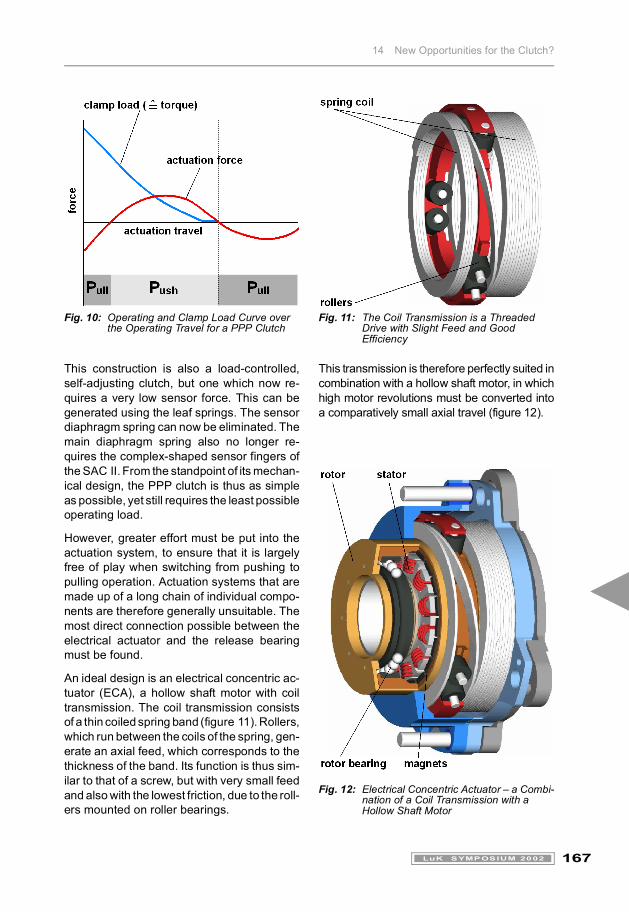
Once we have come to terms with the idea ofreversing the operating load, we can achievea further load reduction by dropping the min-imum point of the release load characteristiccurve below the zero line (figure 9). A secondpart of the operating load characteristic curve
then falls below the zero line, this one occur-ring outside the modulation range in the ven-tilation phase of the clutch (figure 10). The en-tire operating travel now goes through the fol-lowing phases: Pull - Push - Pull. Hence thename PPP clutch.
14 New Opportunities for the Clutch?
167LuK SYMPOSIUM 2002
This construction is also a load-controlled,self-adjusting clutch, but one which now re-quires a very low sensor force. This can begenerated using the leaf springs. The sensordiaphragm spring can now be eliminated. Themain diaphragm spring also no longer re-quires the complex-shaped sensor fingers ofthe SAC II. From the standpoint of its mechan-ical design, the PPP clutch is thus as simpleas possible, yet still requires the least possibleoperating load.
However, greater effort must be put into theactuation system, to ensure that it is largelyfree of play when switching from pushing topulling operation. Actuation systems that aremade up of a long chain of individual compo-nents are therefore generally unsuitable. Themost direct connection possible between theelectrical actuator and the release bearingmust be found.
An ideal design is an electrical concentric ac-tuator (ECA), a hollow shaft motor with coiltransmission. The coil transmission consistsof a thin coiled spring band (figure 11). Rollers,which run between the coils of the spring, gen-erate an axial feed, which corresponds to thethickness of the band. Its function is thus sim-ilar to that of a screw, but with very small feedand also with the lowest friction, due to the roll-ers mounted on roller bearings.
This transmission is therefore perfectly suited incombination with a hollow shaft motor, in whichhigh motor revolutions must be converted intoa comparatively small axial travel (figure 12).
Fig. 12: Electrical Concentric Actuator – a Combi-nation of a Coil Transmission with a Hollow Shaft Motor
Fig. 10: Operating and Clamp Load Curve over the Operating Travel for a PPP Clutch
Fig. 11: The Coil Transmission is a Threaded Drive with Slight Feed and Good Efficiency
14 New Opportunities for the Clutch?
168 LuK SYMPOSIUM 2002
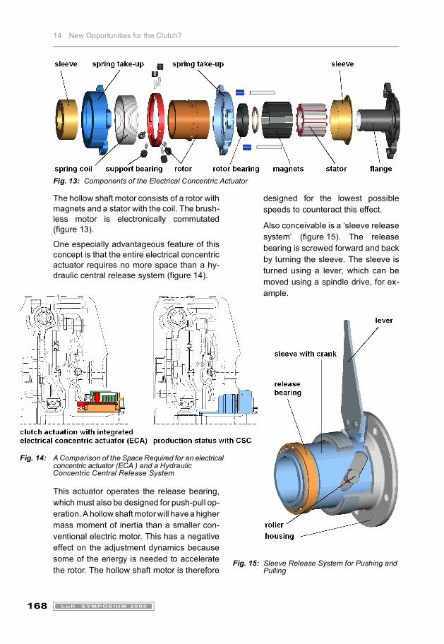
Fig. 13: Components of the Electrical Concentric Actuator
The hollow shaft motor consists of a rotor withmagnets and a stator with the coil. The brush-less motor is electronically commutated(figure 13).
One especially advantageous feature of thisconcept is that the entire electrical concentricactuator requires no more space than a hy-draulic central release system (figure 14).
This actuator operates the release bearing,which must also be designed for push-pull op-eration. A hollow shaft motor will have a highermass moment of inertia than a smaller con-ventional electric motor. This has a negativeeffect on the adjustment dynamics becausesome of the energy is needed to acceleratethe rotor. The hollow shaft motor is therefore
designed for the lowest possiblespeeds to counteract this effect.
Also conceivable is a ‘sleeve releasesystem’ (figure 15). The releasebearing is screwed forward and backby turning the sleeve. The sleeve isturned using a lever, which can bemoved using a spindle drive, for ex-ample.
Fig. 15: Sleeve Release System for Pushing and Pulling
Fig. 14: A Comparison of the Space Required for an electrical concentric actuator (ECA ) and a Hydraulic Concentric Central Release System

14 New Opportunities for the Clutch?
169LuK SYMPOSIUM 2002
Twin ClutchesOne type of transmission that is strongly fa-voured for the future is the parallel shift gear-box (PSG) or twin clutch gearbox, which is de-scribed in more detail in a later article [5]. Brief-ly, the transmission has two input shafts, whichmust be connected to the engine independ-ently of one another with a clutch for each one(figure 16).
Fig. 16: The Principle of the Parallel Shift Gear-box (PSG)
This type of function is not new. There is a ver-sion for farm tractors with one independentpower take-off shaft, which also uses twinclutches (figure 17). Since the operating loadis not as critical for such applications, both par-tial clutches can even be operated with thesame diaphragm spring.
Twin clutches that are suitable for twin clutchgearboxes must have a very compact designand be able to be operated using very smallactuators. Therefore, the findings used forload reduction in single clutches should alsobe used for these.
Fig. 17: Twin Clutch for Tractor for PTO Shaft (Left Clutch) and Master Clutch Operation (Right Clutch)
Figure 18 shows a twin clutch in connectionwith a dual mass flywheel. The two clutchesare somewhat radially interlaced for reasonsof compact design. The larger of the twoclutches is logically used as the start-up clutchand connected with gears 1, 3 and 5.
A more compact unit can be achieved by gen-erating the vibrational isolation with slip con-trol [6]. In connection with two torsion-dampedclutch discs, it replaces the DMFW in auto-matic clutches (figure 19). This likewise re-duces the mass moment of inertia, thus re-ducing fuel consumption, which approximate-ly compensates for the increased consump-tion due to the slip.
So that it is possible to test the PSG complete-ly prior to installation in the vehicle, the twinclutch should be an integral part of the gear-box. It can then be mounted on the engine us-ing a flex-plate, as is done with torque con-verter transmissions.

14 New Opportunities for the Clutch?
170 LuK SYMPOSIUM 2002
Fig. 18: Twin Clutch with DMFW
For especially tight spaces, it is also possible tomount both clutches with only one cover and onewear adjuster (figure 20). The two clutches mustthen wear at approximately the same rate. Toensure similar wear rates in the two clutches, thesecond clutch can be used during start-up.Since the extra wear is generated only in the low-er-wearing clutch, this does not shorten theservice life of the entire system.
Yet another variant is shown in figure 21. It hastwo separate wear adjusters, which areplaced on either side of one clutch cover. Inthis arrangement, only three cast friction sur-faces are required because the middle massis used for both clutches. This mass must bethicker than usual because of the poorer heatdissipation and therefore requires internalventilation.
Fig. 19: Twin Clutch in Connection with Slip Control
Fig. 20: Twin Clutch with One Cover and One Common Wear Adjuster

14 New Opportunities for the Clutch?
171LuK SYMPOSIUM 2002
Fig. 21: Twin Clutch with Shared Cover but Two Separate Wear Adjusters
Fig. 22: Vision of a Double Electrical Concentric Actuator for Twin Clutches
All of the twin clutch concepts shown here canbe combined with the load reducing measuresdescribed before.
Figure 22 shows a variant with a double elec-trical concentric actuator and push/pull oper-ation, similar to figures 11 to 14. It is an ex-
tremely compact unit, which requires the low-est possible operating loads and thus all con-ceivable load reduction measures. Only thenwill a smaller hollow shaft motor be able to op-erate the clutch with a coil transmission.
Another alternative is with a double sleeve re-lease system, which makes fewer demandson the clutch, but requires two externallyplaced actuators (figure 23).
Fig. 23: Double Sleeve Release System
SummaryNew transmission concepts whose main pur-pose is to save fuel lean strongly towards dryclutches, which promise the best efficiency.Demands for less expensive actuators andfaster control require clutches with the small-est possible operating loads. LuK is findingnew ways to reach these goals.
Development will be particularly focused onthe area of dry twin clutches. We have pre-sented several different design options.
Which concept will be given preference will bestrongly influenced by space considerations infuture. What appears ideal for one project canbe unsuitable for the next application.
For this reason, LuK is developing custom so-lutions for various twin clutch projects.
14 New Opportunities for the Clutch?
172 LuK SYMPOSIUM 2002
References[1] Reik, W.: The Self-Adjusting Clutch,
5th LuK Symposium 1994.
[2] Kimmig, K.-L.: The Self-Adjusting Clutchof the 2nd Generation SAC, 6th LuK Sym-posium 1998.
[3] Reik, W.; Kimmig, K.-L.: Selbsteinstel-lende Kupplungen für Kraftfahrzeuge,VDI-Bericht 1323 (1997), p. 105 - 116.
[4] Albers, A.: Selbsteinstellende Kup-plung (SAC) und Zweimassenschwun-grad (ZMS) zur Verbesserung des An-triebsstrangkomforts, VDI Bericht 1175,p. 153 - 168.
[5] Berger, R.; Meinhard, R.; Bünder, C.:The Parallel Shift Gearbox PSG – TwinClutch Gearbox with Dry Clutches,7th LuK Symposium 2002.
[6] Küpper, K.; Seebacher, R.; Werner, O.:Think Systems – Software by LuK,7th LuK Symposium 2002.