Embed Size (px)
Citation preview

Pump Assemblies

Pump Assemblies
Table of ContentsAPI STANDARD RWAC PUMP . . . . . . . . . . . . . . . . . . . . . . . . . . . . . . . . . . . . . 1API STANDARD RWBC PUMP . . . . . . . . . . . . . . . . . . . . . . . . . . . . . . . . . . . . . 2API STANDARD RHAC PUMP . . . . . . . . . . . . . . . . . . . . . . . . . . . . . . . . . . . . . 3API STANDARD RHBC PUMP . . . . . . . . . . . . . . . . . . . . . . . . . . . . . . . . . . . . . 4API STANDARD RWTC PUMP . . . . . . . . . . . . . . . . . . . . . . . . . . . . . . . . . . . . . 5API STANDARD RHTC PUMP . . . . . . . . . . . . . . . . . . . . . . . . . . . . . . . . . . . . . 6API STANDARD THC PUMP — BOX END PLUNGER . . . . . . . . . . . . . . . . . . . 7API STANDARD THC PUMP — PIN END PLUNGER . . . . . . . . . . . . . . . . . . . . 8API STANDARD THM PUMP — BOX END PLUNGER . . . . . . . . . . . . . . . . . . . 9API STANDARD THM PUMP — PIN END PLUNGER . . . . . . . . . . . . . . . . . . 10THOS TYPE PUMP . . . . . . . . . . . . . . . . . . . . . . . . . . . . . . . . . . . . . . . . 11 - 13SLIMHOLE TYPE RWAC PUMP . . . . . . . . . . . . . . . . . . . . . . . . . . . . . . . . . . . 14SLIMHOLE TYPE RWBC PUMP . . . . . . . . . . . . . . . . . . . . . . . . . . . . . . . . . . . 15RXAFR TYPE PUMP . . . . . . . . . . . . . . . . . . . . . . . . . . . . . . . . . . . . . . . . . . . . 16RWAFR TYPE PUMP . . . . . . . . . . . . . . . . . . . . . . . . . . . . . . . . . . . . . . . . . . . 17

www.Q2als.com | 1
API STANDARD RWAC PUMPROD, STATIONARY THIN WALL BARREL, TOP CUP HOLD DOWN PUMP
NOTES:A . Specify length in feet .B . Not shown in the assembly .C . Available either with Friction Ring Hold-Down (RWAFR), Mechanical Hold-
Down (RWAM) or Combination Cup/Mechanical Hold-Down (RWACM) .D . “U” in the part number represents Material .
E . Plunger and Barrel will have additional letters at the end (Examples: 102DCL-F-M-G, U15DLP) C = Spray Metal Coating, L = Length in feet, F = Clearance Fit in thousandths of an inch, M = Monel Pin Ends, G = Grooved Plunger, P = Plating
F . Contact sales for detailed length and material options
Item
API I
tem
QTY
Standard Pump Size 2-3/8” x 1-1/4” 2-3/8” x 1-1/2” 2-7/8” x 2” 3-1/2” x 2-1/2”
API Pump Designation 20-125 RWAC 20-150 RWAC 25-200 RWAC 30-250 RWAC
Description Part Number
Plunger Assembly
1 B21 1 Bushing Valve Rod U23K U23K U23N U23Q
2 R11 1 Rod, ValveA 114FU 114FU 114KU 114NU
3 C12 1 Cage, Top Plunger U47D U47F U47K U47N
4 P21 1 Plunger, One PieceA, E 102DCL-F-M-G 102FCL-F-M-G 102KCL-F-M-G 102NCL-F-M-G
5 C13 1 Cage, Closed, Pin Plunger U39D U39F U39K U39N
6 V11 1 Valve, Ball, and Seat 12DU 12FU 12KU 12PU2
7 P12 1 Plug Seat U98D U98F U98K U98N
Barrel Assembly
8 G11 1 Guide, Valve Rod U70K U70K U70N U70Q
9 S15 1 Bushing, Top Anchor U25KD U25KF U25NK U25QN
10 B11 1 Barrel, Thin WallA, E U15DLP U15FLP U15KLP U15NLP
11 C14 1 Cage, Closed Barrel U37HD U37H U37M U37P
12 V11 1 Valve, Ball, and Seat 12HU 12HU 12MU 12PU2
13 B22 1 Bushing, Seat, Barrel Cage U22K U22K U22N U22Q
Hold-Down Assembly
14 S11 1 Seating Mandrel, Cup, RP U85K U85K U85N U85Q
15 S12 3 Seating Cup, Type HR, RP 625J+30 625J+30 625M+70 625P+70
16 S13 2 Seating Cup Ring, Type HR U110K U110K U110N U110Q
17 S14 1 Seating Cup Nut, Type HR U95K U95K U95N U95Q
Seating Nipple
N11 1 Nipple, Seating, CupB U89K U89K U89N U89Q
Fishing Neck Size
Valve Rod Guide 1 .500” 1 .500” 1 .625” 1 .625”

2 | Pump Assemblies
API STANDARD RWBC PUMPROD, STATIONARY THIN WALL BARREL, BOTTOM CUP HOLD DOWN PUMP
NOTES:A . Specify length in feet .B . Not shown in the assembly .C . Available either with Friction Ring Hold-Down (RWBFR), Mechanical Hold-
Down (RWBM) or Combination Cup/Mechanical Hold-Down (RWBCM) .D . “U” in the part number represents Material .
E . Plunger and Barrel will have additional letters at the end (Examples: 102DCL-F-M-G, U15DLP) C = Spray Metal Coating, L = Length in feet, F = Clearance Fit in thousandths of an inch, M = Monel Pin Ends, G = Grooved Plunger, P = Plating
F . Contact sales for detailed length and material options
Item
API I
tem
QTY
Standard Pump Size 2-3/8” x 1-1/4” 2-3/8” x 1-1/2” 2-7/8” x 2” 3-1/2” x 2-1/2”
API Pump Designation 20-125 RWBC 20-150 RWBC 25-200 RWBC 30-250 RWBC
Description Part Number
Plunger Assembly
1 B21 1 Bushing Valve Rod U23K U23K U23N U23Q
2 R11 1 Rod, ValveA 114FU 114FU 114KU 114NU
3 C12 1 Cage, Top Plunger U47D U47F U47K U47N
4 P21 1 Plunger, One PieceA, E 102DCL-F-M-G 102FCL-F-M-G 102KCL-F-M-G 102NCL-F-M-G
5 C13 1 Cage, Closed, Pin Plunger U39D U39F U39K U39N
6 V11 1 Valve, Ball, and Seat 12DU 12FU 12KU 12PU
7 P12 1 Plug Seat U98D U98F U98K U98N
Barrel Assembly
8 G11 1 Guide, Valve Rod U70K U70K U70N U70Q
9 C21 1 Connector, Upper Barrel U41F U41K U41N U41Q
10 B11 1 Barrel, Thin WallA, E U15DLP U15FLP U15KLP U15NLP
11 C14 1 Cage, Closed Barrel U37HD U37H U37M U37P
12 V11 1 Valve, Ball, and Seat 12HU 12HU 12MU 12PU2
Hold-Down Assembly
13 S11 1 Seating Mandrel, Cup, RP U85K U85K U85N U85Q
14 S12 3 Seating Cup, Type HR, RP 625J+30 625J+30 625M+70 625P+70
15 S13 2 Seating Cup Ring, Type HR U110K U110K U110N U110Q
16 S14 1 Seating Cup Nut, Type HR U95K U95K U95N U95Q
17 S16 1 Coupling, Bottom Anchor U50K U50K U50N U50Q
Seating Nipple
N11 1 Nipple, Seating, CupB U89K U89K U89N U89Q
Fishing Neck Size
Valve Rod Guide 1 .500” 1 .500” 1 .625” 1 .625”

www.Q2als.com | 3
API STANDARD RHAC PUMPROD, STATIONARY HEAVY WALL BARREL, TOP CUP HOLD DOWN PUMP
NOTES:A . Specify length in feet .B . Not shown in the assembly .C . Available either with Friction Ring Hold-Down (RHAFR), Mechanical Hold-
Down (RHAM) or Combination Cup/Mechanical Hold-Down (RHACM) .D . “U” in the part number represents Material .
E . Plunger and Barrel will have additional letters at the end (Examples: 102DCL-F-M-G, U16DLP) C = Spray Metal Coating, L = Length in feet, F = Clearance Fit in thousandths of an inch, M = Monel Pin Ends, G = Grooved Plunger, P = Plating
F . Contact sales for detailed length and material options
Item
API I
tem
QTY
Standard Pump Size 2-3/8” x 1-1/4” 2-7/8” x 1-1/2” 2-7/8” x 1-3/4” 3-1/2” x 2-1/4”
API Pump Designation 20-125 RHAC 25-150 RHAC 25-175 RHAC 30-225 RHAC
Description Part Number
Plunger Assembly
1 B21 1 Bushing Valve Rod U23K U23N U23N U23Q
2 R11 1 Rod, ValveA 114FU 114KU 114KU 114NU
3 C12 1 Cage, Top Plunger U47D U47F U47H U47M
4 P21 1 Plunger, One PieceA, E 102DCL-F-M-G 102FCL-F-M-G 102HCL-F-M-G 102MCL-F-M-G
5 C13 1 Cage, Closed, Pin Plunger U39D U39F U39H U39M
6 V11 1 Valve, Ball, and Seat 12DU 12FU 12HU 12MU
7 P12 1 Plug Seat U98D U98F U98H U98M
Barrel Assembly
8 G11 1 Guide, Valve Rod U70K U70N U70N U70Q
9 S15 1 Bushing, Top Anchor U25KF U25NK U25NK U25QN
10 C31 1 Coupling, Extension U45D U45F U45H U45M
11 B12 1 Barrel, Heavy Wall, RHA, E U16DLP U16FLP U16HLP U16MLP
12 C31 1 Coupling, Extension U45D U45F U45H U45M
13 C14 1 Cage, Closed Barrel U37H U37M U37M U37P
14 V11 1 Valve, Ball, and Seat 12HU 12MU 12MU 12PU2
15 B22 1 Bushing, Seat, Barrel Cage U22K U22N U22N U22Q
Hold-Down Assembly
16 S11 1 Seating Mandrel, Cup, RP U85K U85N U85N U85Q
17 S12 3 Seating Cup, Type HR, RP 625J+30 625M+30 625M+70 625P+70
18 S13 2 Seating Cup Ring, Type HR U110K U110N U110N U110Q
19 S14 1 Seating Cup Nut, Type HR U95K U95N U95N U95Q
Seating Nipple
N11 1 Nipple, Seating, CupB U89K U89N U89N U89Q
Fishing Neck Size
Valve Rod Guide 1 .500” 1 .500” 1 .625” 1 .625”

4 | Pump Assemblies
API STANDARD RHBC PUMPROD, STATIONARY HEAVY WALL BARREL, BOTTOM CUP HOLD DOWN PUMP
NOTES:A . Specify length in feet .B . Not shown in the assembly .C . Available either with Friction Ring Hold-Down (RHBFR), Mechanical Hold-
Down (RHBM) or Combination Cup/Mechanical Hold-Down (RHBCM) .D . “U” in the part number represents Material .
E . Plunger and Barrel will have additional letters at the end (Examples: 102DCL-F-M-G, U16DLP) C = Spray Metal Coating, L = Length in feet, F = Clearance Fit in thousandths of an inch, M = Monel Pin Ends, G = Grooved Plunger, P = Plating
F . Contact sales for detailed length and material options
Item
API I
tem
QTY
Standard Pump Size 2-3/8” x 1-1/4” 2-7/8” x 1-1/2” 2-7/8” x 1-3/4” 3-1/2” x 2-1/4”
API Pump Designation 20-125 RHAC 25-150 RHAC 25-175 RHAC 30-225 RHAC
Description Part Number
Plunger Assembly
1 B21 1 Bushing Valve Rod U23K U23N U23N U23Q
2 R11 1 Rod, ValveA 114FU 114KU 114KU 114NU
3 C12 1 Cage, Top Plunger QU47D QU47F1 QU47H QU47M
4 P21 1 Plunger, One PieceA, E 102DCL-F-M-G 102FCL-F-M-G 102HCL-F-M-G 102MCL-F-M-G
5 C13 1 Cage, Closed, Pin Plunger U39D U39F U39H U39M
6 V11 1 Valve, Ball, and Seat 12DU 12FU 12HU 12MU
7 P12 1 Plug Seat U98D U98F U98H U98M
Barrel Assembly
8 G11 1 Guide, Valve Rod U70K U70N U70N U70Q
9 C21 1 Connector, Upper Barrel U41K U41N U41N U41Q
10 C31 1 Coupling, Extension U45D U45F U45H U45M
11 B12 1 Barrel, Heavy Wall, RHA, E U16DLP U16FLP U16HLP U16MLP
12 C31 1 Coupling, Extension U45D U45F U45H U45M
13 C14 1 Cage, Closed Barrel U37H U37M U37M U37P
14 V11 1 Valve, Ball, and Seat 12HU 12MU 12MU 12PU2
Hold-Down Assembly
15 S11 1 Seating Mandrel, Cup, RP U85K U85N U85N U85Q
16 S12 3 Seating Cup, Type HR, RP 625J+30 625M+30 625M+70 625P+70
17 S13 2 Seating Cup Ring, Type HR U110K U110N U110N U110Q
18 S14 1 Seating Cup Nut, Type HR U95K U95N U95N U95Q
19 S16 1 Coupling, Bottom Anchor U50K U50N U50N U50Q
Seating Nipple
N11 1 Nipple, Seating, CupB U89K U89N U89N U89Q
Fishing Neck Size
Valve Rod Guide 1 .500” 1 .500” 1 .625” 1 .625”
www.Q2als.com | 5
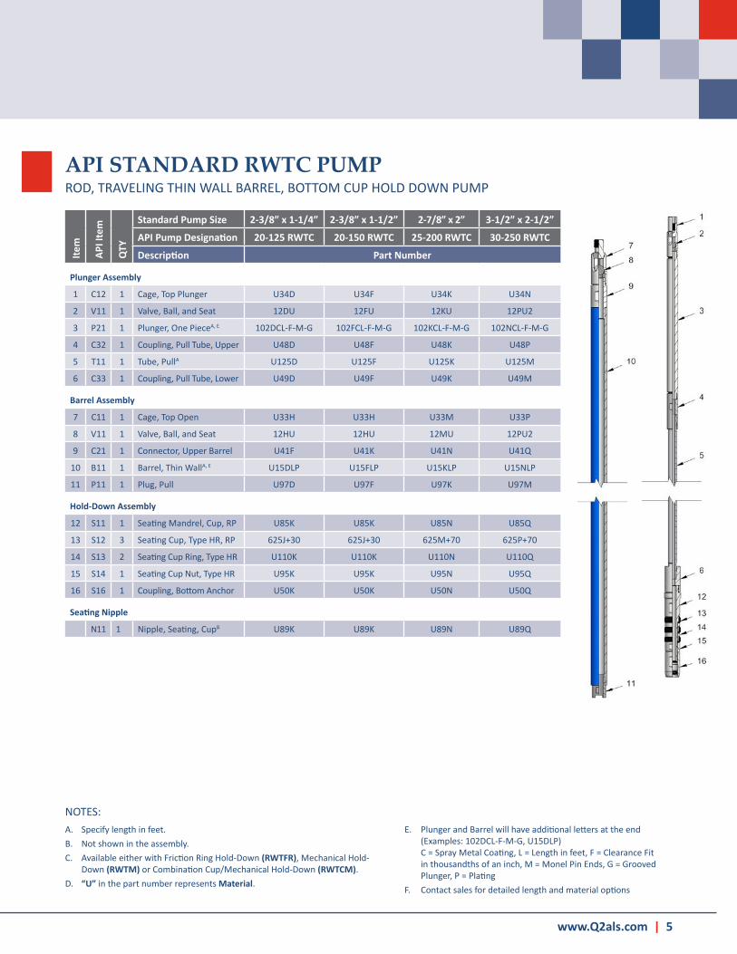
API STANDARD RWTC PUMPROD, TRAVELING THIN WALL BARREL, BOTTOM CUP HOLD DOWN PUMP
NOTES:A . Specify length in feet .B . Not shown in the assembly .C . Available either with Friction Ring Hold-Down (RWTFR), Mechanical Hold-
Down (RWTM) or Combination Cup/Mechanical Hold-Down (RWTCM) .D . “U” in the part number represents Material .
E . Plunger and Barrel will have additional letters at the end (Examples: 102DCL-F-M-G, U15DLP) C = Spray Metal Coating, L = Length in feet, F = Clearance Fit in thousandths of an inch, M = Monel Pin Ends, G = Grooved Plunger, P = Plating
F . Contact sales for detailed length and material options
Item
API I
tem
QTY
Standard Pump Size 2-3/8” x 1-1/4” 2-3/8” x 1-1/2” 2-7/8” x 2” 3-1/2” x 2-1/2”
API Pump Designation 20-125 RWTC 20-150 RWTC 25-200 RWTC 30-250 RWTC
Description Part Number
Plunger Assembly
1 C12 1 Cage, Top Plunger U34D U34F U34K U34N
2 V11 1 Valve, Ball, and Seat 12DU 12FU 12KU 12PU2
3 P21 1 Plunger, One PieceA, E 102DCL-F-M-G 102FCL-F-M-G 102KCL-F-M-G 102NCL-F-M-G
4 C32 1 Coupling, Pull Tube, Upper U48D U48F U48K U48P
5 T11 1 Tube, PullA U125D U125F U125K U125M
6 C33 1 Coupling, Pull Tube, Lower U49D U49F U49K U49M
Barrel Assembly
7 C11 1 Cage, Top Open U33H U33H U33M U33P
8 V11 1 Valve, Ball, and Seat 12HU 12HU 12MU 12PU2
9 C21 1 Connector, Upper Barrel U41F U41K U41N U41Q
10 B11 1 Barrel, Thin WallA, E U15DLP U15FLP U15KLP U15NLP
11 P11 1 Plug, Pull U97D U97F U97K U97M
Hold-Down Assembly
12 S11 1 Seating Mandrel, Cup, RP U85K U85K U85N U85Q
13 S12 3 Seating Cup, Type HR, RP 625J+30 625J+30 625M+70 625P+70
14 S13 2 Seating Cup Ring, Type HR U110K U110K U110N U110Q
15 S14 1 Seating Cup Nut, Type HR U95K U95K U95N U95Q
16 S16 1 Coupling, Bottom Anchor U50K U50K U50N U50Q
Seating Nipple
N11 1 Nipple, Seating, CupB U89K U89K U89N U89Q

6 | Pump Assemblies
API STANDARD RHTC PUMPROD, TRAVELING HEAVY WALL BARREL, BOTTOM CUP HOLD DOWN PUMP
NOTES:A . Specify length in feet .B . Not shown in the assembly .C . Available either with Friction Ring Hold-Down (RHTFR), Mechanical Hold-
Down (RHTM) or Combination Cup/Mechanical Hold-Down (RHTCM) .D . “U” in the part number represents Material .
E . Plunger and Barrel will have additional letters at the end (Examples: 102DCL-F-M-G, U16DLP) C = Spray Metal Coating, L = Length in feet, F = Clearance Fit in thousandths of an inch, M = Monel Pin Ends, G = Grooved Plunger, P = Plating
F . Contact sales for detailed length and material options
Item
API I
tem
QTY
Standard Pump Size 2-3/8” x 1-1/4” 2-7/8” x 1-1/2” 3-1/2” x 2-1/4”
API Pump Designation 20-125 RHTC 25-150 RHTC 30-225 RHTC
Description Part Number
Plunger Assembly
1 C12 1 Cage, Top Plunger U34D U34F U34M
2 V11 1 Valve, Ball, and Seat 12DU 12FU 12MU
3 P21 1 Plunger, One PieceA, E 102DCL-F-M-G 102FCL-F-M-G 102MCL-F-M-G
4 C32 1 Coupling, Pull Tube, Upper U48D U48F U48M
5 T11 1 Tube, PullA U125D U125F U125M
6 C33 1 Coupling, Pull Tube, Lower U49D U49F U49M
Barrel Assembly
7 C11 1 Cage, Top Open U33H U33M U33P
8 V11 1 Valve, Ball, and Seat 12HU 12MU 12PU2
9 C21 1 Connector, Upper Barrel U41K U41N U41Q
10 C31 1 Coupling, Extension U45D U45F U45M
11 B12 1 Barrel, Thin WallA, E U16DLP U16FLP U16MLP
12 C31 1 Coupling, Extension U45D U45F U45M
13 P11 1 Plug, Pull U97D U97F U97M
Hold-Down Assembly
14 S11 1 Seating Mandrel, Cup, RP U85K U85N U85Q
15 S12 3 Seating Cup, Type HR, RP 625J+30 625M+70 625P+70
16 S13 2 Seating Cup Ring, Type HR U110K U110N U110Q
17 S14 1 Seating Cup Nut, Type HR U95K U95N U95Q
18 S16 1 Coupling, Bottom Anchor U50K U50N U50Q
Seating Nipple
N11 1 Nipple, Seating, CupB U89K U89K U89N

www.Q2als.com | 7
API STANDARD THC PUMP — BOX END PLUNGERTUBING, HEAVY WALL BARREL, BOX END PLUNGER CUP HOLD DOWN PUMP
NOTES:A . Specify length in feet .B . Available with Friction Ring Hold-Down (THFR) .C . “U” in the part number represents Material .D . Plunger and Barrel will have additional letters at the end (Examples: 100HCL-F, U17HLP)
C = Spray Metal Coating, L = Length in feet, F = Clearance Fit in thousandths of an inch, P = PlatingE . Contact sales for detailed length and material options
Item
API I
tem
QTY
Standard Pump Size 2-3/8” x 1-3/4” 2-7/8” x 2-1/4” 3-1/2” x 2-3/4”
API Pump Designation 20-175 THC 25-225 THC 30-275 THC
Description Part Number
Plunger Assembly
1 C11 1 Cage, Top Open U33H U33M U33P
2 V11 1 Valve, Ball, and Seat 12HU 12MU 12PU
3 C22 1 Connector, Box Plunger U42H U42M U42P
4 P23 1 Plunger, Box End, TPA, D 100HCL-F 100MCL-F 100PCL-F
5 C15 1 Cage, Closed, Box Plunger U40H U40M U40P
6 V11 1 Valve, Ball, and Seat 12HU 12MU 12PU2
7 P31 1 Puller, Standing Valve U106H U106M U106P
Barrel Assembly
8 C34 2 Coupling, Tubing U70-1 U70-2 U70-3
9 N21 1 Nipple, Extension, UpperA U88K U88N U88Q
10 C35 2 Coupling, Barrel U46H U46M U46P
11 B13 1 Barrel, Heavy Wall, TPA, D U17HLP U17MLP U17PLP
12 N22 1 Nipple, Extension, LowerA U88K-1 U88N-1 U88Q-1
13 N13 1 Nipple, Seating, 2 Cup Type U90K U90N U90Q
Standing Valve Assembly
14 C16 1 Cage, Standing Valve U35H U35M U35P
15 V11 1 Valve, Ball, and Seat 12HU 12MU 12PU
16 S17 1 Seating Mandrel, Cup, TP U86H1 U86M1 U86P
17 S18 2 Seating Cup, Type HR, TP 625H-10 625M-10 625P-10
18 S13 1 Seating Cup Ring, Type HR U110K U110N U110Q
19 S14 1 Seating Cup Nut, Type HR U95K U95N U95Q
20 S16 1 Coupling, Bottom Anchor U50K U50N U50Q

8 | Pump Assemblies
API STANDARD THC PUMP — PIN END PLUNGERTUBING, HEAVY WALL BARREL, PIN END PLUNGER CUP HOLD DOWN PUMP
NOTES:A . Specify length in feet .B . Available with Friction Ring Hold-Down (THFR) .C . “U” in the part number represents Material .D . Plunger and Barrel will have additional letters at the end (Examples: 102HCL-F-M-G, U17HLP)
C = Spray Metal Coating, L = Length in feet, F = Clearance Fit in thousandths of an inch, M = Monel Pin Ends, G = Grooved Plunger, P = PlatingE . Contact sales for detailed length and material options
Item
API I
tem
QTY
Standard Pump Size 2-3/8” x 1-3/4” 2-7/8” x 2-1/4” 3-1/2” x 2-3/4”
API Pump Designation 20-175 THC 25-225 THC 30-275 THC
Description Part Number
Plunger Assembly
1 C11 1 Cage, Top Open U33H U33M U33P
2 V11 1 Valve, Ball, and Seat 12HU 12MU 12PU
3 P21 1 Plunger, One PieceA, D 102HCL-F-M-G 102MCL-F-M-G 102PCL-F-M-G
4 C13 1 Cage, Closed, Pin Plunger U39H U39M U39P
5 V11 1 Valve, Ball, and Seat 12HU 12MU 12PU2
6 P31 1 Puller, Standing Valve U106H U106M U106P
Barrel Assembly
7 C34 2 Coupling, Tubing U70-1 U70-2 U70-3
8 N21 1 Nipple, Extension, UpperA U88K U88N U88Q
9 C35 2 Coupling, Barrel U46H U46M U46P
10 B13 1 Barrel, Heavy Wall, TPA, D U17HLP U17MLP U17PLP
11 N22 1 Nipple, Extension, LowerA U88K-1 U88N-1 U88Q-1
12 N13 1 Nipple, Seating, 2 Cup Type U90K U90N U90Q
Standing Valve Assembly
13 C16 1 Cage, Standing Valve U35H U35M U35P
14 V11 1 Valve, Ball, and Seat 12HU 12MU 12PU
15 S17 1 Seating Mandrel, Cup, TP U86H1 U86M1 U86P
16 S18 2 Seating Cup, Type HR, TP 625H-10 625M-10 625P-10
17 S13 1 Seating Cup Ring, Type HR U110K U110N U110Q
18 S14 1 Seating Cup Nut, Type HR U95K U95N U95Q
19 S16 1 Coupling, Bottom Anchor U50K U50N U50Q

www.Q2als.com | 9
API STANDARD THM PUMP — BOX END PLUNGERTUBING, HEAVY WALL BARREL, BOX END PLUNGER MECHANICAL HOLD DOWN
NOTES:A . Specify length in feet .B . “U” in the part number represents Material .C . Plunger and Barrel will have additional letters at the end (Examples: 100HCL-F, U17HLP)
C = Spray Metal Coating, L = Length in feet, F = Clearance Fit in thousandths of an inch, P = PlatingD . Contact sales for detailed length and material options
Item
API I
tem
QTY
Standard Pump Size 2-3/8” x 1-3/4” 2-7/8” x 2-1/4” 3-1/2” x 2-3/4” 4-1/2” x 3-3/4”
API Pump Designation 20-175 THM 25-225 THM 30-275 THM 40-375 THM
Description Part Number
Plunger Assembly
1 C11 1 Cage, Top Open U33H U33M U33P U33T
2 V11 1 Valve, Ball, and Seat 12HU 12MU 12PU 12TU
3 C22 1 Connector, Box Plunger U42H U42M U42P U42T
4 P23 1 Plunger, Box End, TPA, C 100HCL-F 100MCL-F 100PCL-F 100TCL-F
5 C15 1 Cage, Closed, Box Plunger U40H U40M U40P U40T
6 V11 1 Valve, Ball, and Seat 12HU 12MU 12PU2 12TU
7 P31 1 Puller, Standing Valve U106H U106M U106P U106T
Barrel Assembly
8 C34 2 Coupling, Tubing U70-1 U70-2 U70-3 U70-4
9 N21 1 Nipple, Extension, UpperA U88K U88N U88Q U88U
10 C35 2 Coupling, Barrel U46H U46M U46P U46T
11 B13 1 Barrel, Heavy Wall, TPA, C U17HLP U17MLP U17PLP U17TLP
12 N22 1 Nipple, Extension, LowerA U88K-1 U88N-1 U88Q-1 U88U-1
13 N13 1 Nipple, Seating, 2 Cup Type U92K U92N U92Q U92U
Standing Valve Assembly
14 C16 1 Cage, Standing Valve U35H U35M U35P U35T
15 V11 1 Valve, Ball, and Seat 12HU 12MU 12PU 12TU
16 S22 1 Bushing, Mechanical Bottom Lock
U26K U26N U26Q U26U
17 S22 1 Seal Ring, Mechanical Bottom Lock
U108K U108N U108Q U108U
18 S22 1 Mandrel, Mechanical Bottom Lock
U83K U83N U83Q U83U

10 | Pump Assemblies
API STANDARD THM PUMP — PIN END PLUNGERTUBING, HEAVY WALL BARREL, PIN END PLUNGER MECHANICAL HOLD DOWN
NOTES:A . Specify length in feet .B . “U” in the part number represents Material .C . Plunger and Barrel will have additional letters at the end (Examples: 102HCL-F-M-G, U17HLP)
C = Spray Metal Coating, L = Length in feet, F = Clearance Fit in thousandths of an inch, M = Monel Pin Ends, G = Grooved Plunger, P = PlatingD . Contact sales for detailed length and material options
Item
API I
tem
QTY
Standard Pump Size 2-3/8” x 1-3/4” 2-7/8” x 2-1/4” 3-1/2” x 2-3/4” 4-1/2” x 3-3/4”
API Pump Designation 20-175 THM 25-225 THM 30-275 THM 40-375 THM
Description Part Number
Plunger Assembly
1 C11 1 Cage, Top Open U33H U33M U33P U33T
2 V11 1 Valve, Ball, and Seat 12HU 12MU 12PU 12TU
3 P21 1 Plunger, One PieceA, C 102HCL-F-M-G 102MCL-F-M-G 102PCL-F-M-G 102TCL-F-M-G
4 C13 1 Cage, Closed, Pin Plunger U39H U39M U39P U39T
5 V11 1 Valve, Ball, and Seat 12HU 12MU 12PU2 12TU
6 P31 1 Puller, Standing Valve U106H U106M U106P U106T
Barrel Assembly
7 C34 2 Coupling, Tubing U70-1 U70-2 U70-3 U70-4
8 N21 1 Nipple, Extension, UpperA U88K U88N U88Q U88U
9 C35 2 Coupling, Barrel U46H U46M U46P U46T
10 B13 1 Barrel, Heavy Wall, TPA, C U17HLP U17MLP U17PLP U17TLP
11 N22 1 Nipple, Extension, LowerA U88K-1 U88N-1 U88Q-1 U88U-1
12 N13 1 Nipple, Seating, 2 Cup Type U92K U92N U92Q U92U
Standing Valve Assembly
13 C16 1 Cage, Standing Valve U35H U35M U35P U35T
14 V11 1 Valve, Ball, and Seat 12HU 12MU 12PU 12TU
15 S22 1 Bushing, Mechanical Bottom Lock
U26K U26N U26Q U26U
16 S22 1 Seal Ring, Mechanical Bottom Lock
U108K U108N U108Q U108U
17 S22 1 Mandrel, Mechanical Bottom Lock
U83K U83N U83Q U83U

www.Q2als.com | 11
THOS TYPE PUMPTUBING OVERSIZE, HEAVY WALL BARREL, BOX END PLUNGER PUMP
NOTES:A . Specify length in feet .B . “U” in the part number represents Material .C . Plunger and Barrel will have additional letters at the end (Examples: 100MCL-F, U18MLP)
C = Spray Metal Coating, L = Length in feet, F = Clearance Fit in thousandths of an inch, P = PlatingD . Contact sales for detailed length and material options
Item
QTY
Standard Pump Size 2-3/8” x 2-1/4” 2-7/8” x 2-3/4” 2-7/8” x 3-1/4” 3-1/2” x 3-1/4”
Pump Designation 20-225 THOS 25-275 THOS 25-325 THOS 30-325 THOS
Description Part Number
Plunger Assembly
1 1 On & Off Tool, Magnum 160KW-BM 160NW-BM 160NX-BM 160QX-BM
2 1 Rod, PolishedA 651D(L)W 651D(L)W 651F(L)X 651F(L)X
3 1 Coupling, Polished Rod UPR54W UPR54W UPR54X1 UPR54X1
4 1 Cage, Top Open U33M U33P U33R1 U33R1
5 1 Valve, Ball, and Seat 12MU 12PU 12RU 12RU
6 1 Connector, Box End Plunger U42M U42P U42R U42R
7 1 Plunger, Box End, TPA, C 100MCL-F 100PCL-F 100RCL-F 100RCL-F
8 1 Cage, Closed, Box Plunger U40M U40P U40R U40R
9 1 Valve, Ball, and Seat 12MU 12PU2 12RU 12RU
10 1 Plug, Seat U98M-C U98P-C U98R-C U98R-C
Barrel Assembly
11 1 Connector, Upper, Barrel THOS U88K2M U43NP U43NR U43QR
12 1 Barrel, Heavy Wall, RPA, C U18MLP U18PLP U18RLP U18RLP
13 1 Cage, Closed Barrel U37P-C U37R-C U37T-C U37T-C
14 1 Valve, Ball, and Seat 12PU2 12RU 12TU 12TU
15 1 Nut, Lock - U95R-S 95T-S 95T-S
16 1 Bushing, Seat, Barrel Cage U22Q U43NP-1 U43NR-1 U43QR-1

12 | Pump Assemblies
THOS TYPE PUMPTUBING OVERSIZE, HEAVY WALL BARREL, BOX END PLUNGER PUMP
NOTES:A . Specify length in feet .B . “U” in the part number represents Material .C . Plunger and Barrel will have additional letters at the end (Examples: 100TCL-F, U18TLP)
C = Spray Metal Coating, L = Length in feet, F = Clearance Fit in thousandths of an inch, P = PlatingD . Contact sales for detailed length and material options
Item
QTY
Standard Pump Size 3-1/2” x 3-3/4” 4-1/2” x 4-3/4” 4-1/2” x 5-3/4”
Pump Designation 30-375 THOS 40-475 THOS 40-575 THOS
Description Part Number
Plunger Assembly
1 1 On & Off Tool, Magnum 160QX-BM 160UY-BM 160UY-BM
2 1 Rod, PolishedA 651F(L)X 651F(L)Y 651F(L)Y
3 1 Coupling, Polished Rod UPR55X1 UPR54Y UPR54Y
4 1 Cage, Top Open U33T U33ZB U33ZC
5 1 Valve, Ball, and Seat 12TU 12ZBU 12ZCU
6 1 Connector, Box End Plunger U42T U42ZB U42ZC
7 1 Plunger, Box End, TPA, C 100TCL-F 100ZBCL-F 100ZCCL-F
8 1 Cage, Closed, Box Plunger U40T U40ZB U40ZC
9 1 Valve, Ball, and Seat 12TU 12ZBU 12ZCU
10 1 Plug, Seat U98M-C U98ZB-C U98ZC-C
Barrel Assembly
11 1 Connector, Upper, Barrel THOS U43QT U43UZB U43UZC
12 1 Barrel, Heavy Wall, RPA, C U18TLP U18ZBLP U18ZCLP
13 1 Cage, Closed Barrel U37Z-C U37ZB-C U37ZC-C
14 1 Valve, Ball, and Seat 12TU2 12ZBU 12ZCU
15 1 Bushing, Seat, Barrel Cage U22Z U22ZB U22ZC

www.Q2als.com | 13
THOS TYPE PUMPTUBING OVERSIZE, HEAVY WALL BARREL, BOX END PLUNGER PUMP
NOTES:A . Specify length in feet .B . “U” in the part number represents Material .C . Plunger and Barrel will have additional letters at the end (Examples: Q100ZACL-F, QU18ZALP)
C = Spray Metal Coating, L = Length in feet, F = Clearance Fit in thousandths of an inch, P = PlatingD . Contact sales for detailed length and material options
Item
QTY
Standard Pump Size 5-1/2” x 5-1/2” 7” x 7-3/4”
Pump Designation 50-550 THOS 65-775 THOS
Description Part Number
Plunger Assembly
1 1 On & Off Tool, Magnum Q160UY-BM Q160UY-BM
2 1 Rod, PolishedA Q651F(L)Y Q651F(L)Y
3 1 Coupling, Polished Rod QUPR54Y QUPR54Y
4 1 Cage, Top Open QU33ZA QU33ZF
5 1 Valve, Ball, and Seat Q12ZAU Q12ZFU
6 1 Connector, Box End Plunger QU42ZA QU42ZF
7 1 Plunger, Box End, TPA, C Q100ZACL-F Q100ZFCL-F
8 1 Cage, Closed, Box Plunger QU40ZA QU40ZF
9 1 Valve, Ball, and Seat Q12ZAU Q12ZFU
10 1 Plug, Seat QU98ZA-C QU98ZF-C
Barrel Assembly
11 1 Connector, Upper, Barrel THOS QU43UZA QU43ZF3
12 1 Barrel, Heavy Wall, RPA, C QU18ZALP QU18ZFLP
13 1 Cage, Closed Barrel QU37ZA-C QU37ZF-C
14 1 Valve, Ball, and Seat Q12ZAU Q12ZFU
15 1 Bushing, Seat, Barrel Cage QU22ZA QU22ZF

14 | Pump Assemblies
SLIMHOLE TYPE RWAC PUMPROD, STATIONARY THIN WALL BARREL, TOP CUP HOLD DOWN PUMP
NOTES:A . Specify length in feet .B . Not shown in the assembly .C . “U” in the part number represents Material .D . Plunger and Barrel will have additional letters at the end (Examples: Q102DCL-F-M-G, QU15DLP)
C = Spray Metal Coating, L = Length in feet, F = Clearance Fit in thousandths of an inch, M = Monel Pin Ends, G = Grooved Plunger, P = PlatingE . Contact sales for detailed length and material options
Item
API I
tem
QTY
Standard Pump Size 2-1/16” x 1-1/4”
Nominal 1.70” x 1-1/4”
Description Part Number
Plunger Assembly
1 B21 1 Bushing Valve Rod QU23K
2 R11 1 Rod, ValveA Q114FU
3 C12 1 Cage, Top Plunger QU47D
4 P21 1 Plunger, One PieceA, D Q102DCL-F-M-G
5 C13 1 Cage, Closed, Pin Plunger QU39D
6 V11 1 Valve, Ball, and Seat Q12DU
7 P12 1 Plug Seat QU98D
Barrel Assembly
8 G11 1 Guide, Valve Rod QU70K
9 S15 1 Bushing, Top Anchor QU25FD
10 B11 1 Barrel, Thin WallA, D QU15DLP
11 - 1 Bushing, Adapter, Barrel to Cage QU24FD
12 C14 1 Cage, Closed Barrel QU38F
13 V11 1 Valve, Ball, and Seat Q12FU
14 B22 1 Bushing, Seat, Barrel Cage QU22F
Hold-Down Assembly
15 S31 1 Seating Mandrel, Cup, Type O QU85F1
16 S32 3 Seating Cup, Type O Q626F+70
17 S33 2 Seating Cup Ring, Type O QU110F
18 S34 1 Seating Cup Nut, Type O QU95F
Seating Nipple
1 Nipple, Seating, 1.540” ID Integral Joint-1-1/2” 10RD Upset w/1.540” ID.B QU89F1
Fishing Neck Size
Valve Rod Guide 1 .250”
www.Q2als.com | 15
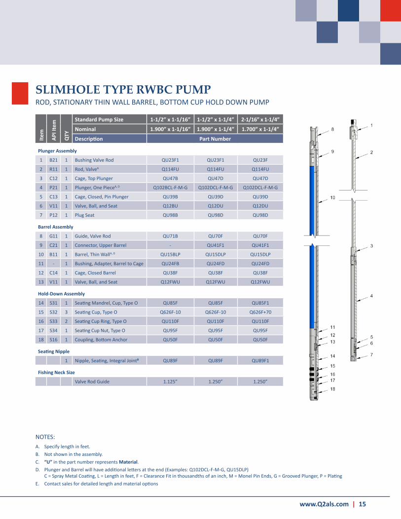
SLIMHOLE TYPE RWBC PUMPROD, STATIONARY THIN WALL BARREL, BOTTOM CUP HOLD DOWN PUMP
NOTES:A . Specify length in feet .B . Not shown in the assembly .C . “U” in the part number represents Material .D . Plunger and Barrel will have additional letters at the end (Examples: Q102DCL-F-M-G, QU15DLP)
C = Spray Metal Coating, L = Length in feet, F = Clearance Fit in thousandths of an inch, M = Monel Pin Ends, G = Grooved Plunger, P = PlatingE . Contact sales for detailed length and material options
Item
API I
tem
QTY
Standard Pump Size 1-1/2” x 1-1/16” 1-1/2” x 1-1/4” 2-1/16” x 1-1/4”
Nominal 1.900” x 1-1/16” 1.900” x 1-1/4” 1.700” x 1-1/4”
Description Part Number
Plunger Assembly
1 B21 1 Bushing Valve Rod QU23F1 QU23F1 QU23F
2 R11 1 Rod, ValveA Q114FU Q114FU Q114FU
3 C12 1 Cage, Top Plunger QU47B QU47D QU47D
4 P21 1 Plunger, One PieceA, D Q102BCL-F-M-G Q102DCL-F-M-G Q102DCL-F-M-G
5 C13 1 Cage, Closed, Pin Plunger QU39B QU39D QU39D
6 V11 1 Valve, Ball, and Seat Q12BU Q12DU Q12DU
7 P12 1 Plug Seat QU98B QU98D QU98D
Barrel Assembly
8 G11 1 Guide, Valve Rod QU71B QU70F QU70F
9 C21 1 Connector, Upper Barrel - QU41F1 QU41F1
10 B11 1 Barrel, Thin WallA, D QU15BLP QU15DLP QU15DLP
11 - 1 Bushing, Adapter, Barrel to Cage QU24FB QU24FD QU24FD
12 C14 1 Cage, Closed Barrel QU38F QU38F QU38F
13 V11 1 Valve, Ball, and Seat Q12FWU Q12FWU Q12FWU
Hold-Down Assembly
14 S31 1 Seating Mandrel, Cup, Type O QU85F QU85F QU85F1
15 S32 3 Seating Cup, Type O Q626F-10 Q626F-10 Q626F+70
16 S33 2 Seating Cup Ring, Type O QU110F QU110F QU110F
17 S34 1 Seating Cup Nut, Type O QU95F QU95F QU95F
18 S16 1 Coupling, Bottom Anchor QU50F QU50F QU50F
Seating Nipple
1 Nipple, Seating, Integral JointB QU89F QU89F QU89F1
Fishing Neck Size
Valve Rod Guide 1 .125” 1 .250” 1 .250”

16 | Pump Assemblies
RXAFR TYPE PUMPROD, BIG BORE STATIONARY HEAVY WALL BARREL | TOP METAL FRICTION RING HOLD DOWN
NOTES:A . Specify length in feet .B . Not shown in the assembly .C . Available with other Metal Ring Friction Hold-Down.D . “U” in the part number represents Material .
Item
QTY
Standard Pump Size 4-1/2” x 3-1/4” 5-1/2” x 3-3/4” 7” x 5-1/2”
Pump Designation 40-325 RXAFR 50-375 RXAFR 65-550 RXAFR
Description Part Number
Plunger Assembly
1 1 Bushing, Valve Rod QU23U QU23U1 QU23U1
2 1 Rod, ValveA Q651F(L)X Q651F(L)Y Q651F(L)Y
3 1 Coupling, Polished Rod QUPR54X1 QUPR54Y1 QUPR54Y
4 1 Cage, Top Open QU33R1 QU33T QU33ZA
5 1 Valve, Ball, and Seat Q12RU Q12TU Q12ZAU
6 1 Connector, Top Plunger QU42R QU42T QU42ZA
7 1 Plunger, Box EndA, E Q100RCL-F Q100TCL-F Q100ZACL-F
8 1 Cage, Closed, Box End Plunger QU40R QU40T QU40ZA
9 1 Valve, Ball, and Seat Q12RU Q12TU Q12ZAU
10 1 Bushing, Seat, Barrel Cage QU98R QU98T QU98ZA
Barrel Assembly
11 1 Guide, Valve Rod QU70U1 QU70Z1 QU70ZA
12 1 Bushing, Top Hold-Down QU25UR QU25ZT QU25ZA
13 1 Barrel, THOS/RX, Heavy WallA, E QU18RLP QU18TLP QU18ZALP
14 1 Cage, Closed Barrel QU37TM QU37Z QU37ZA
15 1 Valve, Ball, and Seat Q12TU2 Q12TU2 Q12ZAU
16 1 Bushing, Seat, Barrel Cage QU22T QU22Z QU22ZA
Hold-Down Assembly
17 1 Mandrel, Hold-Down, 2-Wide Ring QU85U1 QU85Z QU85ZA1
18 2 Ring, Friction QU112U1 QU112Z1 QU112ZA1
19 2 Ring Spacer QU113U1 QU113Z1 QU113ZA1
20 1 Nut, Lock QU95U1 QU95Z1 QU95ZA1
Seating Nipple
1 Nipple, SeatingB QU89U QU89Z QU89ZA
E . Plunger and Barrel will have additional letters at the end (Examples: Q100RCL-F, QU18RLP) C = Spray Metal Coating, L = Length in feet, F = Clearance Fit in thousandths of an inch, P = Plating
F . Contact sales for detailed length and material options

www.Q2als.com | 17
NOTES:A . Specify length in feet .B . Not shown in the assembly .C . Available with other Metal Ring Friction Hold-Down.D . “U” in the part number represents Material .
E . Plunger and Barrel will have additional letters at the end (Examples: Q102KCL-F-M-G, QU15KLP) C = Spray Metal Coating, L = Length in feet, F = Clearance Fit in thousandths of an inch, M = Monel Pin Ends, G = Grooved Plunger, P = Plating
F . Contact sales for detailed length and material options
RWAFR TYPE PUMPROD, STATIONARY THIN WALL BARREL | TOP METAL FRICTION RING HOLD DOWN
Item
QTY
Standard Pump Size 2-7/8” x 2” 3-1/2” x 2-1/2”
Pump Designation 25-200 RWAFR 30-250 RWAFR
Description Part Number
Plunger Assembly
1 1 Bushing Valve Rod QU23N QU23Q
2 1 Rod, ValveA Q114KU Q114NU
3 1 Cage, Top Plunger QU47K QU47N
4 1 Plunger, One PieceA, E Q102KCL-F-M-G Q102NCL-F-M-G
5 1 Cage, Closed, Pin Plunger QU39K QU39N
6 1 Valve, Ball, and Seat Q12KU Q12PU2
7 1 Plug Seat QU98K QU98N
Barrel Assembly
8 1 Guide, Valve Rod QU70N QU70Q
9 1 Bushing, Top Anchor QU25NK QU25QN
10 1 Barrel, Thin WallA, E QU15KLP QU15NLP
11 1 Cage, Closed Barrel QU37M QU37P
12 1 Valve, Ball, and Seat Q12MU Q12PU2
13 1 Bushing, Seat, Barrel Cage QU22N QU22Q
Hold-Down Assembly
14 1 Mandrel, Hold-Down, 2-Wide Ring QU85N1 QU85Q1
15 2 Ring, Friction QU112N1 QU112P1
16 2 Ring Spacer QU113N1 QU113P1
17 1 Nut, Lock QU95N1 QU95Q1
Seating Nipple
1 Nipple, Seating, CupB QU89N QU89Q
Fishing Neck Size
Valve Rod Guide 1 .625” 1 .625”

Contact your local sales representative by visiting our website or find a location
near you.
Q2 ALS CORPORATE OFFICE CANADA 7883 Edgar Industrial WayRed Deer, AB T4P 3R2 CanadaP: 403 .343 .8802E: sales@Q2als .com
Q2 ALS CORPORATE OFFICE USA 3611 Hwy 158Midland, TX 79706P: 432 .685 .2600E: sales@Q2als .com
www .Q2als .com