Embed Size (px)
Citation preview

P1: FCH
GB098-FM GB098-Miller September 21, 2004 18:7 Char Count= 0
AudelTM
Pumps and HydraulicsAll New 6th Edition
i
P1: FCH
GB098-FM GB098-Miller September 21, 2004 18:7 Char Count= 0
AudelTM
Pumps and HydraulicsAll New 6th Edition
Rex MillerMark Richard Miller
Harry Stewart
i
P1: FCH
GB098-FM GB098-Miller September 21, 2004 18:7 Char Count= 0
Vice President and Executive Group Publisher: Richard SwadleyVice President and Publisher: Joseph B. WikertExecutive Editor: Carol A. LongEditorial Manager: Kathryn A. MalmDevelopment Editor: Kevin ShaferProduction Editor: Vincent KunkemuellerText Design & Composition: TechBooks
Copyright C© 2004 by Wiley Publishing, Inc., Indianapolis, Indiana. All rights reserved.Published simultaneously in Canada
No part of this publication may be reproduced, stored in a retrieval system or transmitted in anyform or by any means, electronic, mechanical, photocopying, recording, scanning or otherwise,except as permitted under Sections 107 or 108 of the 1976 United States Copyright Act, withouteither the prior written permission of the Publisher, or authorization through payment of theappropriate per-copy fee to the Copyright Clearance Center, 222 Rosewood Drive, Danvers, MA01923, (978) 750-8400, fax (978) 646-8600. Requests to the Publisher for permission should beaddressed to the Legal Department, Wiley Publishing, Inc., 10475 Crosspoint Blvd., Indianapolis,IN 46256, (317) 572-3447, fax (317) 572-4355, e-mail: [email protected].
Limit of Liability/Disclaimer of Warranty: The publisher and the author make no representa-tions or warranties with respect to the accuracy or completeness of the contents of this workand specifically disclaim all warranties, including without limitation warranties of fitness for aparticular purpose. No warranty may be created or extended by sales or promotional materials.The advice and strategies contained herein may not be suitable for every situation. This workis sold with the understanding that the publisher is not engaged in rendering legal, accounting,or other professional services. If professional assistance is required, the services of a competentprofessional person should be sought. Neither the publisher nor the author shall be liable fordamages arising herefrom. The fact that an organization or Website is referred to in this workas a citation and/or a potential source of further information does not mean that the author orthe publisher endorses the information the organization or Website may provide or recommen-dations it may make. Further, readers should be aware that Internet Websites listed in this workmay have changed or disappeared between when this work was written and when it is read.
For general information on our other products and services please contact our Customer CareDepartment within the United States at (800) 762-2974, outside the United States at (317) 572-3993 or fax (317) 572-4002.
Trademarks: Wiley, the Wiley Publishing logo, Audel, and The Books That Work are trademarksor registered trademarks of John Wiley & Sons, Inc. and/or its affiliates. All other trademarksare the property of their respective owners. Wiley Publishing, Inc., is not associated with anyproduct or vendor mentioned in this book.
Wiley also publishes its books in a variety of electronic formats. Some content that appears inprint may not be available in electronic books.
Library of Congress Control Number:
Printed in the United States of America
10 9 8 7 6 5 4 3 2 1
ii
eISBN: 0-7645-7911-8
P1: FCH
GB098-FM GB098-Miller September 21, 2004 18:7 Char Count= 0
Contents
Acknowledgments xiii
About the Authors xv
Introduction xvii
PART I INTRODUCTION TO BASICPRINCIPLES OF PUMPS ANDHYDRAULICS
Chapter 1 Basic Fluid Principles 3Physics 3
Matter 3Body 4Energy 5Heat 7Pressure 14Barometer 21Gravity 22Force 26Motion 28Friction 34Work and Power 36
Basic Machines 38Lever 40Wheel and Axle 41Pulley 42Inclined Plane 43Screw 44Wedge 45
Water 46Properties of Water with Respect toPump Design 53Pressure at Different Depths 54Compressibility of Water 54
iii
P1: FCH
GB098-FM GB098-Miller September 21, 2004 18:7 Char Count= 0
iv Contents
Air 57Humidity 57Weight of Air 60
Summary 61Review Questions 62
Chapter 2 Principles of Hydraulics 65Basic Principles 65Hydrostatics 69
Static Head 70Static Lift 70Displacement 72Buoyancy 73Hydrostatic Paradox 76Hydrostatic Balance 76
Hydrodynamics 77Dynamic Head 77Dynamic Lift 78Total Column 84Friction of Water in Pipes 84
Flow of Water 89Measurement of Water Flow 89Siphon 96Flow through Orifices 97Specific Gravity 102
Summary 106Review Questions 109
PART II PUMPS
Chapter 3 Centrifugal Pumps 113Basic Principles 113
Pumps Having Straight Vanes 114Pump Having Curved Vanes 114The Volute 115Curvature of the Impeller Vanes 117
Basic Classification 117
P1: FCH
GB098-FM GB098-Miller September 21, 2004 18:7 Char Count= 0
Contents v
Single-Stage Pump 118Multistage Pump 119Impellers 120Balancing 123
Construction of Pumps 127Casing or Housing 127Impeller 127Stuffing-Box Assembly 129Bearings and Housings 129Shaft Assembly 131Drive 131
Installation 133Location 133Foundation 135Leveling 135Grouting 137Inlet Piping 137Discharge Piping 138Pumps Handling High-TemperatureLiquids 138
Operation 139Priming 140Starting the Pump 143Stopping the Pump 145Abnormal Operating Conditions 146
Troubleshooting 146Reduced Capacity or Pressure andFailure to Deliver Water 147Loses Water after Starting 147Pump Overloads Driver 147Pump Vibrates 148Pointers on Pump Operation 148
Maintenance and Repair 149Lateral End Clearances 149Parts Renewals 149Pointers on Assembly 150
P1: FCH
GB098-FM GB098-Miller September 21, 2004 18:7 Char Count= 0
vi Contents
Corrosion-Resisting Centrifugal Pumps 152Typical Application — Plating 152Corrosion-Resisting Pump Installation 155Maintenance 157
Corrosion-Resisting PumpTroubleshooting 158
Pump-End Assembly and Disassembly 158Good Safety Practices 161
Impeller Design Considerations 162Velocity of Impeller 163Total Hydraulic Load or Lift 164Velocity Head 164
Summary 173Review Questions 174
Chapter 4 Rotary Pumps 177Principles of Operation 177
Gear-Type Pumps 177Vane-Type Pumps 180Piston-Type Pumps 187
Construction 188Gear-Type Pumps 190Vane-Type Pumps 199Piston-Type Pumps 200
Installation and Operation 204Alignment 204Drives for Rotary Gear Pumps 208Power for Driving Pumps 208Piping 209Direction of Rotation 210Starting and Operating the Pump 212Practical Installation 212Types of Gear Pumps 213Pressure Relief Valve 215
Rotary Pump Troubleshooting 216No Liquid Delivered 216Insufficient Liquid Delivered 217
P1: FCH
GB098-FM GB098-Miller September 21, 2004 18:7 Char Count= 0
Contents vii
Pump Delivers for a Short Period, ThenQuits 217Rapid Wear 217Pump Requires Too Much Power 218Noisy Operation 218
Calculations 218Correct Size of Pump 219Friction of Water in Pipes 219Friction Loss in Rubber Hose 219Dynamic Column or Total Load 221Dynamic Lift 221Dynamic Head 222Horsepower Required 224
Summary 225Review Questions 228
Chapter 5 Reciprocating Pumps 229Principles of Operation 229
Lift Pumps 230Force Pumps 231Self-Priming or Siphon Pumps 239
Construction 240Calculations 243
Lift 243Size of Discharge Pipe 248Head 248Displacement 250Piston Speed 251Slip 252Capacity 253Efficiency 254
Summary 260Review Questions 262
Chapter 6 Special-Service Pumps 265Service Pumps 265Chemical and Process Pumps 270
P1: FCH
GB098-FM GB098-Miller September 21, 2004 18:7 Char Count= 0
viii Contents
Pumps for Medical Use 273Pumps for Handling of Sewage 274Other Special-Service Pumps 275
Magma Pumps 276Sump Pumps 276Irrigation Pumps 281Diaphragm-Type Pumps 282Open-Diaphragm Pump 284Advantages of Diaphragm Pumps 284Shallow-Well and Deep-WellPumps 287
Rubber Impeller Pumps 296Principles of Operation 297Marine Applications 297
Tubing Pumps 298Basic Principle of Operation 299Lubricating the Tubing 301Variable Speed 301Types Available 301Air Driven Pump 311Multi-Tube Pumps 311Chemical Pumping 312
Summary 312Review Questions 313
PART III HYDRAULICS
Chapter 7 Hydraulic Accumulators 317Basic Construction and Operation 317Types of Accumulators 318
Weight-Loaded 319Spring-Loaded Accumulators 324Air- or Gas-Type Accumulators 324Shock Absorbers or Alleviators 331
Air and Vacuum Chambers 334Air Chambers 334Vacuum Chambers 335
P1: FCH
GB098-FM GB098-Miller September 21, 2004 18:7 Char Count= 0
Contents ix
Accumulator Circuits 338Summary 342Review Questions 344
Chapter 8 Power Transmission 345Hydraulic Drives 345
Basic Operating Principles 346Tangential Acceleration 348Tangential Deceleration 351
Types of Hydraulic Drives 352Fluid Drive 352Hydraulic Drive 356Twin-Disk Hydraulic Drive 357Hydraulic Torque Converter 358Hydrostatic Transmission Systems 359Hydraulic Adjustable-Speed Drive 367Farm Tractor Applications 368Pumps for Robots 371CCS Systems 378
Summary 381Review Questions 382
Chapter 9 Hydraulic Power Tools 383Hydraulic Circuits 383
Hydraulic Motors 385Types of Hydraulic Motors 389
Hydraulically Controlled Circuits 394Combination Pump and Control Valve Unit 394Remote Directional Control Valves 395Operation of a Cylinder on a Machine Tool 398Circuit Elements 398
Operation of the Hydraulic Circuit 402Summary 403Review Questions 403
Chapter 10 Hydraulic Cylinders 405Nonrotating Cylinders 405
Names of Parts 407
P1: FCH
GB098-FM GB098-Miller September 21, 2004 18:7 Char Count= 0
x Contents
Force Developed in NonrotatingCylinders 415Installation 418Eccentric Loads 421Causes of Failure 422Repair and Maintenance 423
Rotating Cylinders 424Names of Parts 424Installation 428Failure 430Repair and Maintenance 430
Summary 432Review Questions 432
Chapter 11 Control Valves 435Pressure Controls 437
Pressure Relief 437Sequence 438Pressure Reducing 439Counterbalance and Unloading 440Operating Signals 441
Flow Controls 441Needle 444Noncompensating 444Compensating 445
Directional Controls 447Summary 450Review Questions 451
Chapter 12 Hydraulic Control Valve Operators 453Pressure-Control Valve Operators 453Flow-Control Valve Operators 454Directional Control Valve Operators 456
Manual Operators 456Solenoid Operators 460Mechanical Operators 463Pilot Operators 465
P1: FCH
GB098-FM GB098-Miller September 21, 2004 18:7 Char Count= 0
Contents xi
Summary 468Review Questions 469
PART IV FLUIDS, LINES, AND FITTINGS
Chapter 13 Hydraulic Fluids 473Petroleum-Base Fluids 473Synthetic-Base Fluids 473Quality Requirements 474Maintenance 475Change of Fluids in a Hydraulic System 476Selection of a Hydraulic Fluid 477
Specific Weight 477Viscosity 478Saybolt Universal Viscosimeter 478Viscosity Problems 480Viscosity Index 480Lubricating Value 481Pour Point 481Oxidation and Contamination 481
Hydraulic Filters 482Mobile-type Hydraulic Filter Units 485
Summary 488Review Questions 488
Chapter 14 Fluid Lines and Fittings 491Rigid Pipe 491Semi-Rigid (Tubing) 492
Manufacturing Process 495Other Types 497Installation of Tubing 498
Flexible Piping (Hose) 499Manifolds 505Summary 507Review Questions 507
Appendix A Pump Resources 509
P1: FCH
GB098-FM GB098-Miller September 21, 2004 18:7 Char Count= 0
xii Contents
Appendix B Oils and Fluids 511
Appendix C Latest Pumps Available 513
Index 531
P1: FCH
GB098-FM GB098-Miller September 21, 2004 18:7 Char Count= 0
Acknowledgments
No book can be written without the aid of many people. It takes agreat number of individuals to put together the information avail-able about any particular technical field into a book. The field ofpumps and hydraulics is no exception. Many firms have contributedinformation, illustrations, and analysis of the book.
The authors would like to thank every person involved for hisor her contributions. Following are some of the firms that suppliedtechnical information and illustrations.
Abex Corp., Denison DivisionABSThe Aldrich Pump Company, Standard Pump Div.Becker PumpsBrown and Sharpe Mfg. Co.Buffalo Forge CompanyBuffalo PumpsCaterpillar Tractor Co.Commercial Shearing Inc.Continental HydraulicsDeming Division, Crane Co.Double A Products Co.Gold PumpsGould PumpsHydreco, Div. of General SignalImperial-Eastern Corp.Logansport Machine Co., Inc.Lynair, Inc.Marvel Engineering Co.Mobile Aerial Towers, Inc.Oilgear CompanyParker-Hannifin Corp.Pathon Manufacturing Company, Div. of Parker-Hannifin Corp.Pleuger Submersible Pumps, Inc.Rexnard, Inc., Hydraulic Component Div.Roper Pump CompanSchrader Div., Scovil Mfg. Co.Sherwood
xiii
P1: FCH
GB098-FM GB098-Miller September 21, 2004 18:7 Char Count= 0
xiv Acknowledgments
Snap-Tite, Inc.Sperry Vickers, Division of Sperry Rand Corp.Sunstrand Hydro-Transmission, Div. of Sundstrand Corp.Superior Hydraulics, Div. of Superior Pipe SpecialtiesTAT EngineeringViking Pump DivisionThe Weatherhead Co.
P1: FCH
GB098-FM GB098-Miller September 21, 2004 18:7 Char Count= 0
About the Authors
Rex Miller was a Professor of Industrial Technology at The StateUniversity of New York, College at Buffalo for more than 35 years.He has taught at the technical school, high school, and college levelfor more than 40 years. He is the author or co-author of more than100 textbooks ranging from electronics through carpentry and sheetmetal work. He has contributed more than 50 magazine articles overthe years to technical publications. He is also the author of sevencivil war regimental histories.
Mark Richard Miller finished his BS in New York and moved onto Ball State University, where he earned a master’s degree, thenwent to work in San Antonio. He taught high school and finishedhis doctorate in College Station, Texas. He took a position at TexasA&M University in Kingsville, Texas, where he now teaches in theIndustrial Technology Department as a Professor and DepartmentChairman. He has co-authored 11 books and contributed manyarticles to technical magazines. His hobbies include refinishing a1970 Plymouth Super Bird and a 1971 Road-runner.
Harry L. Stewart was a professional engineer and is the author ofnumerous books for the trades covering pumps, hydraulics, pneu-matics, and fluid power.
xv

P1: FCH
GB098-FM GB098-Miller September 21, 2004 18:7 Char Count= 0
xvi
P1: FCH
GB098-FM GB098-Miller September 21, 2004 18:7 Char Count= 0
Introduction
The purpose of this book is to provide a better understanding ofthe fundamentals and operating principles of pumps, pump con-trols, and hydraulics. A thorough knowledge of pumps has becomemore important, due to the large number of applications of pumpequipment in industry.
The applied principles and practical features of pumps and hy-draulics are discussed in detail. Various installations, operations,and maintenance procedures are also covered. The information con-tained will be of help to engineering students, junior engineers anddesigners, installation and maintenance technicians, shop mechan-ics, and others who are interested in technical education and self-advancement.
The correct servicing methods are of the utmost importance to theservice technician, since time and money can be lost when repeatedrepairs are required. With the aid of this book, you should be ableto install and service pumps for nearly any application.
The authors would like to thank those manufacturers that pro-vided illustrations, technical information, and constructive criticism.Special thanks to TAT Engineering and Sherwood Pumps.
xvii

P1: FCH
GB098-FM GB098-Miller September 21, 2004 18:7 Char Count= 0
xviii
P1: FCH
GB098-01 GB098-Miller September 13, 2004 17:28 Char Count= 0
Part I
Introduction to BasicPrinciples of Pumpsand Hydraulics
1

P1: FCH
GB098-01 GB098-Miller September 13, 2004 17:28 Char Count= 0
2
P1: FCH
GB098-01 GB098-Miller September 13, 2004 17:28 Char Count= 0
Chapter 1Basic Fluid PrinciplesPumps are devices that expend energy to raise, transport, or com-press fluids. The earliest pumps were made for raising water. Theseare known today as Persian and Roman waterwheels and the moresophisticated Archimedes screw.
Mining operations of the Middle Ages led to development of thesuction or piston pump. There are many types of suction pumps.They were described by Georgius Agricola in his De re Metallicawritten in 1556 a.d. A suction pump works by atmospheric pressure.That means when the piston is raised, it creates a partial vacuum.The outside atmospheric pressure then forces water into the cylinder.From there, it is permitted to escape by way of an outlet valve.Atmospheric pressure alone can force water to a maximum heightof about 34 feet (10 meters). So, the force pump was developed todrain deeper mines. The downward stroke of the force pump forceswater out through a side valve. The height raised depends on theforce applied to the piston.
Fluid is employed in a closed system as a medium to cause motion,either linear or rotary. Because of improvements in seals, materials,and machining techniques, the use of fluids to control motions hasgreatly increased in the recent past.
Fluid can be either in a liquid or gaseous state. Air, oil, water,oxygen, and nitrogen are examples of fluids. They can all be pumpedby today’s highly improved devices.
PhysicsA branch of science that deals with matter and energy and theirinteractions in the field of mechanics, electricity, nuclear phenomena,and others is called physics. Some of the basic principles of fluidsmust be studied before subsequent chapters in this book can beunderstood properly.
MatterMatter can be defined as anything that occupies space, and all matterhas inertia. Inertia is that property of matter by which it will remainat rest or in uniform motion in the same straight line or direction un-less acted upon by some external force. Matter is any substance thatcan be weighed or measured. Matter may exist in one of three states:
� Solid (coal, iron, ice)� Liquid (oil, alcohol, water)� Gas (air, hydrogen, helium)
3
P1: FCH
GB098-01 GB098-Miller September 13, 2004 17:28 Char Count= 0
4 Chapter 1
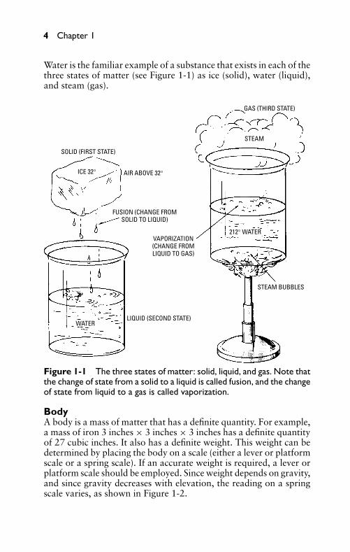
Water is the familiar example of a substance that exists in each of thethree states of matter (see Figure 1-1) as ice (solid), water (liquid),and steam (gas).
SOLID (FIRST STATE)
AIR ABOVE 32°ICE 32°
FUSION (CHANGE FROMSOLID TO LIQUID)
VAPORIZATION(CHANGE FROMLIQUID TO GAS)
WATERLIQUID (SECOND STATE)
212° WATER
STEAM BUBBLES
STEAM
GAS (THIRD STATE)
Figure 1-1 The three states of matter: solid, liquid, and gas. Note thatthe change of state from a solid to a liquid is called fusion, and the changeof state from liquid to a gas is called vaporization.
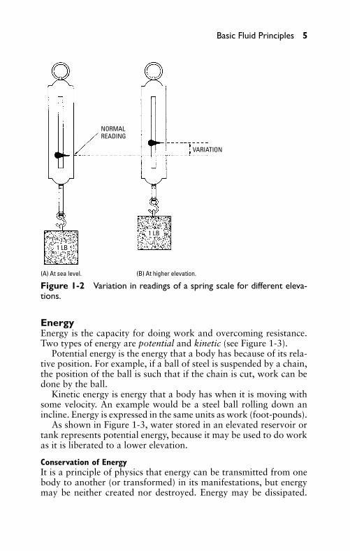
BodyA body is a mass of matter that has a definite quantity. For example,a mass of iron 3 inches × 3 inches × 3 inches has a definite quantityof 27 cubic inches. It also has a definite weight. This weight can bedetermined by placing the body on a scale (either a lever or platformscale or a spring scale). If an accurate weight is required, a lever orplatform scale should be employed. Since weight depends on gravity,and since gravity decreases with elevation, the reading on a springscale varies, as shown in Figure 1-2.
P1: FCH
GB098-01 GB098-Miller September 13, 2004 17:28 Char Count= 0
Basic Fluid Principles 5
NORMALREADING
VARIATION
(A) At sea level. (B) At higher elevation.
1 LB
1 LB
Figure 1-2 Variation in readings of a spring scale for different eleva-tions.
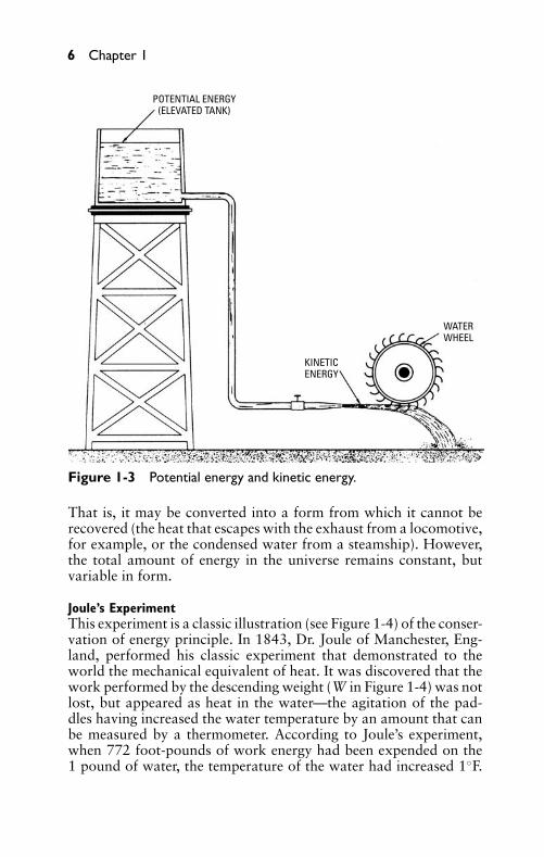
EnergyEnergy is the capacity for doing work and overcoming resistance.Two types of energy are potential and kinetic (see Figure 1-3).
Potential energy is the energy that a body has because of its rela-tive position. For example, if a ball of steel is suspended by a chain,the position of the ball is such that if the chain is cut, work can bedone by the ball.
Kinetic energy is energy that a body has when it is moving withsome velocity. An example would be a steel ball rolling down anincline. Energy is expressed in the same units as work (foot-pounds).
As shown in Figure 1-3, water stored in an elevated reservoir ortank represents potential energy, because it may be used to do workas it is liberated to a lower elevation.
Conservation of EnergyIt is a principle of physics that energy can be transmitted from onebody to another (or transformed) in its manifestations, but energymay be neither created nor destroyed. Energy may be dissipated.
P1: FCH
GB098-01 GB098-Miller September 13, 2004 17:28 Char Count= 0
6 Chapter 1
POTENTIAL ENERGY(ELEVATED TANK)
KINETICENERGY
WATERWHEEL
Figure 1-3 Potential energy and kinetic energy.
That is, it may be converted into a form from which it cannot berecovered (the heat that escapes with the exhaust from a locomotive,for example, or the condensed water from a steamship). However,the total amount of energy in the universe remains constant, butvariable in form.
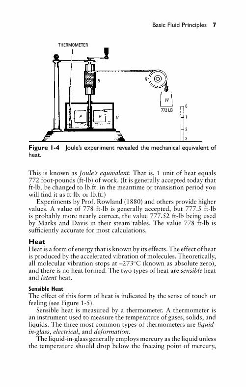
Joule’s ExperimentThis experiment is a classic illustration (see Figure 1-4) of the conser-vation of energy principle. In 1843, Dr. Joule of Manchester, Eng-land, performed his classic experiment that demonstrated to theworld the mechanical equivalent of heat. It was discovered that thework performed by the descending weight (W in Figure 1-4) was notlost, but appeared as heat in the water—the agitation of the pad-dles having increased the water temperature by an amount that canbe measured by a thermometer. According to Joule’s experiment,when 772 foot-pounds of work energy had been expended on the1 pound of water, the temperature of the water had increased 1◦F.
P1: FCH
GB098-01 GB098-Miller September 13, 2004 17:28 Char Count= 0
Basic Fluid Principles 7
THERMOMETER
0
1
3
772 LB
B R
W
VP P
2
Figure 1-4 Joule’s experiment revealed the mechanical equivalent ofheat.
This is known as Joule’s equivalent: That is, 1 unit of heat equals772 foot-pounds (ft-lb) of work. (It is generally accepted today thatft-lb. be changed to lb.ft. in the meantime or transistion period youwill find it as ft-lb. or lb.ft.)
Experiments by Prof. Rowland (1880) and others provide highervalues. A value of 778 ft-lb is generally accepted, but 777.5 ft-lbis probably more nearly correct, the value 777.52 ft-lb being usedby Marks and Davis in their steam tables. The value 778 ft-lb issufficiently accurate for most calculations.
HeatHeat is a form of energy that is known by its effects. The effect of heatis produced by the accelerated vibration of molecules. Theoretically,all molecular vibration stops at –273◦C (known as absolute zero),and there is no heat formed. The two types of heat are sensible heatand latent heat.
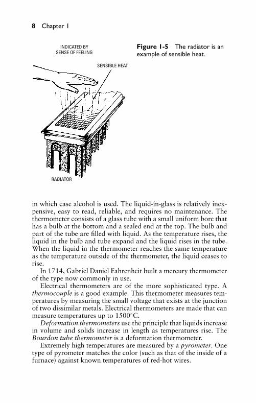
Sensible HeatThe effect of this form of heat is indicated by the sense of touch orfeeling (see Figure 1-5).
Sensible heat is measured by a thermometer. A thermometer isan instrument used to measure the temperature of gases, solids, andliquids. The three most common types of thermometers are liquid-in-glass, electrical, and deformation.
The liquid-in-glass generally employs mercury as the liquid unlessthe temperature should drop below the freezing point of mercury,
P1: FCH
GB098-01 GB098-Miller September 13, 2004 17:28 Char Count= 0
8 Chapter 1
INDICATED BYSENSE OF FEELING
SENSIBLE HEAT
RADIATOR
Figure 1-5 The radiator is anexample of sensible heat.
in which case alcohol is used. The liquid-in-glass is relatively inex-pensive, easy to read, reliable, and requires no maintenance. Thethermometer consists of a glass tube with a small uniform bore thathas a bulb at the bottom and a sealed end at the top. The bulb andpart of the tube are filled with liquid. As the temperature rises, theliquid in the bulb and tube expand and the liquid rises in the tube.When the liquid in the thermometer reaches the same temperatureas the temperature outside of the thermometer, the liquid ceases torise.
In 1714, Gabriel Daniel Fahrenheit built a mercury thermometerof the type now commonly in use.
Electrical thermometers are of the more sophisticated type. Athermocouple is a good example. This thermometer measures tem-peratures by measuring the small voltage that exists at the junctionof two dissimilar metals. Electrical thermometers are made that canmeasure temperatures up to 1500◦C.
Deformation thermometers use the principle that liquids increasein volume and solids increase in length as temperatures rise. TheBourdon tube thermometer is a deformation thermometer.
Extremely high temperatures are measured by a pyrometer. Onetype of pyrometer matches the color (such as that of the inside of afurnace) against known temperatures of red-hot wires.
P1: FCH
GB098-01 GB098-Miller September 13, 2004 17:28 Char Count= 0
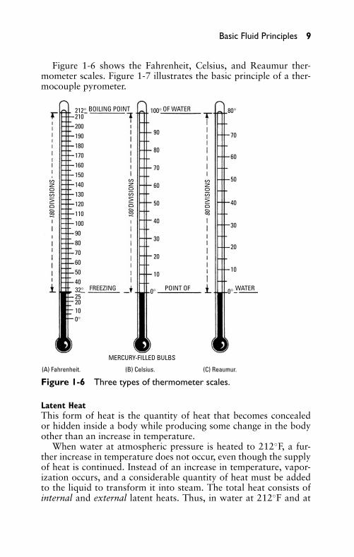
Basic Fluid Principles 9
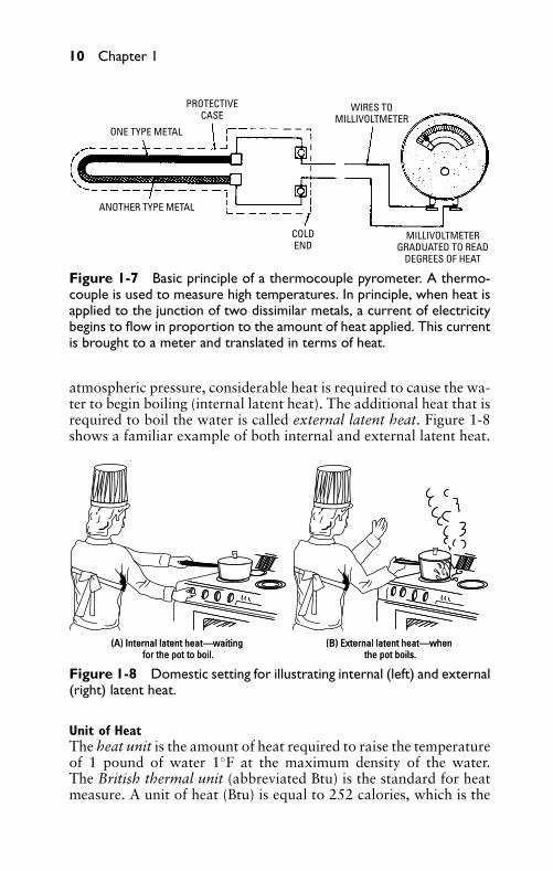
Figure 1-6 shows the Fahrenheit, Celsius, and Reaumur ther-mometer scales. Figure 1-7 illustrates the basic principle of a ther-mocouple pyrometer.
BOILING POINT OF WATER
FREEZING POINT OF WATER
212° 100°
0°
80°
0°
210200190180170160150140130120110100908070605040
2520100°
90
80
70
60
50
40
30
20
10
70
60
50
40
30
20
10
32°
MERCURY-FILLED BULBS
(A) Fahrenheit. (B) Celsius. (C) Reaumur.
180
DIVI
SION
S
80 D
IVIS
ION
S
100
DIVI
SION
S
Figure 1-6 Three types of thermometer scales.
Latent HeatThis form of heat is the quantity of heat that becomes concealedor hidden inside a body while producing some change in the bodyother than an increase in temperature.
When water at atmospheric pressure is heated to 212◦F, a fur-ther increase in temperature does not occur, even though the supplyof heat is continued. Instead of an increase in temperature, vapor-ization occurs, and a considerable quantity of heat must be addedto the liquid to transform it into steam. The total heat consists ofinternal and external latent heats. Thus, in water at 212◦F and at
P1: FCH
GB098-01 GB098-Miller September 13, 2004 17:28 Char Count= 0
10 Chapter 1
PROTECTIVECASE
WIRES TOMILLIVOLTMETER
ANOTHER TYPE METAL
COLDEND
MILLIVOLTMETERGRADUATED TO READ
DEGREES OF HEAT
ONE TYPE METAL
Figure 1-7 Basic principle of a thermocouple pyrometer. A thermo-couple is used to measure high temperatures. In principle, when heat isapplied to the junction of two dissimilar metals, a current of electricitybegins to flow in proportion to the amount of heat applied. This currentis brought to a meter and translated in terms of heat.
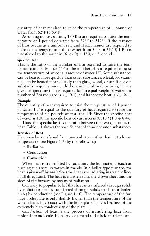
atmospheric pressure, considerable heat is required to cause the wa-ter to begin boiling (internal latent heat). The additional heat that isrequired to boil the water is called external latent heat. Figure 1-8shows a familiar example of both internal and external latent heat.
(A) Internal latent heat—waiting for the pot to boil.
(B) External latent heat—when the pot boils.
(A) Internal latent heat—waiting for the pot to boil.
(B) External latent heat—when the pot boils.
Figure 1-8 Domestic setting for illustrating internal (left) and external(right) latent heat.
Unit of HeatThe heat unit is the amount of heat required to raise the temperatureof 1 pound of water 1◦F at the maximum density of the water.The British thermal unit (abbreviated Btu) is the standard for heatmeasure. A unit of heat (Btu) is equal to 252 calories, which is the
P1: FCH
GB098-01 GB098-Miller September 13, 2004 17:28 Char Count= 0
Basic Fluid Principles 11
quantity of heat required to raise the temperature of 1 pound ofwater from 62◦F to 63◦F.
Assuming no loss of heat, 180 Btu are required to raise the tem-perature of 1 pound of water from 32◦F to 212◦F. If the transferof heat occurs at a uniform rate and if six minutes are required toincrease the temperature of the water from 32◦F to 212◦F, 1 Btu istransferred to the water in (6 × 60) ÷ 180, or 2 seconds.
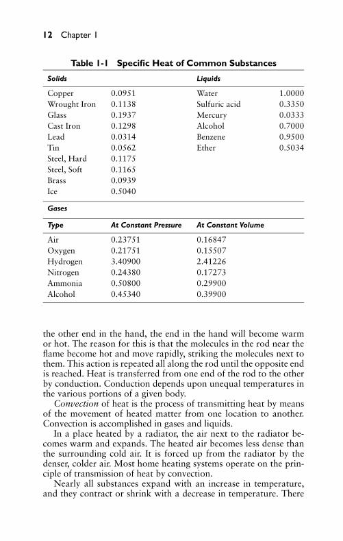
Specific HeatThis is the ratio of the number of Btu required to raise the tem-perature of a substance 1◦F to the number of Btu required to raisethe temperature of an equal amount of water 1◦F. Some substancescan be heated more quickly than other substances. Metal, for exam-ple, can be heated more quickly than glass, wood, or air. If a givensubstance requires one-tenth the amount of heat to bring it to agiven temperature than is required for an equal weight of water, thenumber of Btu required is 1/10 (0.1), and its specific heat is 1/10 (0.1).
ExampleThe quantity of heat required to raise the temperature of 1 poundof water 1◦F is equal to the quantity of heat required to raise thetemperature of 8.4 pounds of cast iron 1◦F. Since the specific heatof water is 1.0, the specific heat of cast iron is 0.1189 (1.0 ÷ 8.4).
Thus, the specific heat is the ratio between the two quantities ofheat. Table 1-1 shows the specific heat of some common substances.
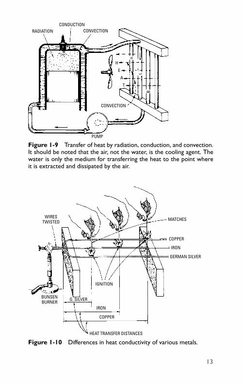
Transfer of HeatHeat may be transferred from one body to another that is at a lowertemperature (see Figure 1-9) by the following:
� Radiation� Conduction� Convection
When heat is transmitted by radiation, the hot material (such asburning fuel) sets up waves in the air. In a boiler-type furnace, theheat is given off by radiation (the heat rays radiating in straight linesin all directions). The heat is transferred to the crown sheet and thesides of the furnace by means of radiation.
Contrary to popular belief that heat is transferred through solidsby radiation; heat is transferred through solids (such as a boiler-plate) by conduction (see Figure 1-10). The temperature of the fur-nace boilerplate is only slightly higher than the temperature of thewater that is in contact with the boilerplate. This is because of theextremely high conductivity of the plate.
Conduction of heat is the process of transferring heat frommolecule to molecule. If one end of a metal rod is held in a flame and
P1: FCH
GB098-01 GB098-Miller September 13, 2004 17:28 Char Count= 0
12 Chapter 1
Table 1-1 Specific Heat of Common Substances
Solids Liquids
Copper 0.0951 Water 1.0000Wrought Iron 0.1138 Sulfuric acid 0.3350Glass 0.1937 Mercury 0.0333Cast Iron 0.1298 Alcohol 0.7000Lead 0.0314 Benzene 0.9500Tin 0.0562 Ether 0.5034Steel, Hard 0.1175Steel, Soft 0.1165Brass 0.0939Ice 0.5040
Gases
Type At Constant Pressure At Constant Volume
Air 0.23751 0.16847Oxygen 0.21751 0.15507Hydrogen 3.40900 2.41226Nitrogen 0.24380 0.17273Ammonia 0.50800 0.29900Alcohol 0.45340 0.39900
the other end in the hand, the end in the hand will become warmor hot. The reason for this is that the molecules in the rod near theflame become hot and move rapidly, striking the molecules next tothem. This action is repeated all along the rod until the opposite endis reached. Heat is transferred from one end of the rod to the otherby conduction. Conduction depends upon unequal temperatures inthe various portions of a given body.
Convection of heat is the process of transmitting heat by meansof the movement of heated matter from one location to another.Convection is accomplished in gases and liquids.
In a place heated by a radiator, the air next to the radiator be-comes warm and expands. The heated air becomes less dense thanthe surrounding cold air. It is forced up from the radiator by thedenser, colder air. Most home heating systems operate on the prin-ciple of transmission of heat by convection.
Nearly all substances expand with an increase in temperature,and they contract or shrink with a decrease in temperature. There
P1: FCH
GB098-01 GB098-Miller September 13, 2004 17:28 Char Count= 0
PUMP
CONVECTION
CONVECTIONRADIATIONCONDUCTION
H
E
A
T
B.
t.
u.
Figure 1-9 Transfer of heat by radiation, conduction, and convection.It should be noted that the air, not the water, is the cooling agent. Thewater is only the medium for transferring the heat to the point whereit is extracted and dissipated by the air.
WIRESTWISTED MATCHES
COPPER
IRON
GERMAN SILVER
IGNITION
COPPER
IRON
G. SILVERBUNSENBURNER
HEAT TRANSFER DISTANCES
Figure 1-10 Differences in heat conductivity of various metals.
13
P1: FCH
GB098-01 GB098-Miller September 13, 2004 17:28 Char Count= 0
14 Chapter 1
is one exception to this statement for all temperature changes, theexception being water. It is a remarkable characteristic of water thatat its maximum density (39.1◦F) water expands as heat is added andthat it also expands slightly as the temperature decreases from thatpoint.
Increase in heat causes a substance to expand, because of anincrease in the velocity of molecular action. Since the moleculesbecome more separated in distance by their more frequent violentcollisions, the body expands.
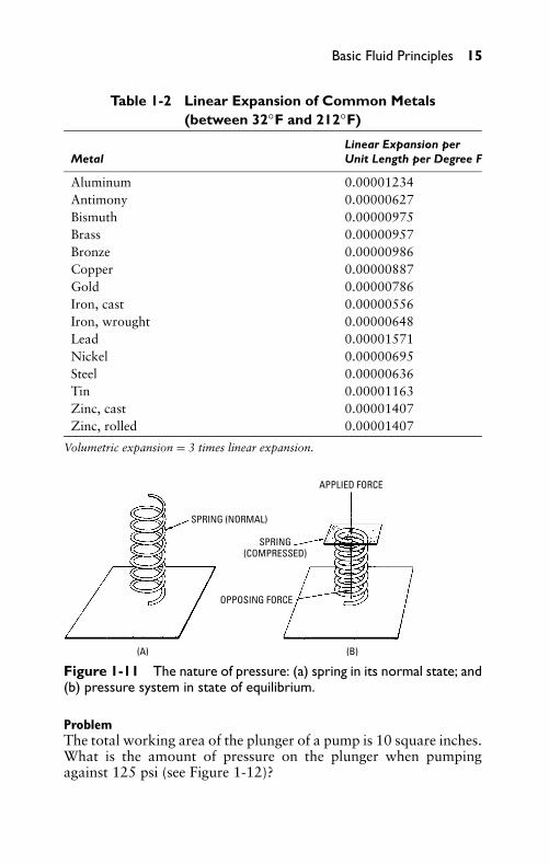
Linear expansion is the expansion in a longitudinal direction ofsolid bodies, while volumetric expansion is the expansion in volumeof a substance.
The coefficient of linear expansion of a solid substance is the ratioof increase in length of body to its original length, produced by anincrease in temperature of 1◦F.
Expansion and contraction caused by a change in temperaturehave some advantages, but also pose some disadvantages. For ex-ample, on the plus side, rivets are heated red-hot for applying tobridge girders, structural steel, and large boilerplates. As the rivetscool, they contract, and provide a solid method of fastening. Ironrims are first heated and then placed on the wheel. As the iron cools,the rim contracts and binds the wheel so that it will not come off.Common practice is to leave a small space between the ends of thesteel sections that are laid end on end. This is to allow for longitu-dinal expansion and contraction. Table 1-2 shows values that canbe used in calculation of linear expansion.
Some of the disadvantages of expansion and contraction causedby change in temperatures are setting up of high stresses, distortion,misalignment, and bearing problems.
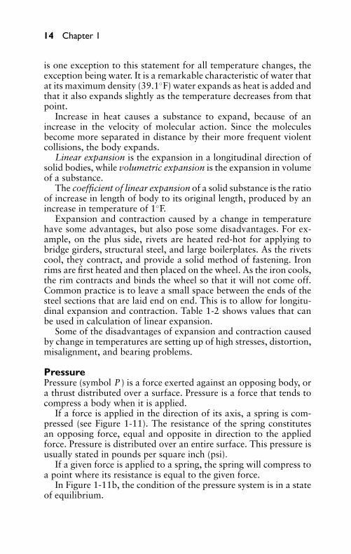
PressurePressure (symbol P ) is a force exerted against an opposing body, ora thrust distributed over a surface. Pressure is a force that tends tocompress a body when it is applied.
If a force is applied in the direction of its axis, a spring is com-pressed (see Figure 1-11). The resistance of the spring constitutesan opposing force, equal and opposite in direction to the appliedforce. Pressure is distributed over an entire surface. This pressure isusually stated in pounds per square inch (psi).
If a given force is applied to a spring, the spring will compress toa point where its resistance is equal to the given force.
In Figure 1-11b, the condition of the pressure system is in a stateof equilibrium.
P1: FCH
GB098-01 GB098-Miller September 13, 2004 17:28 Char Count= 0
Basic Fluid Principles 15
Table 1-2 Linear Expansion of Common Metals(between 32◦F and 212◦F)
Linear Expansion perMetal Unit Length per Degree F
Aluminum 0.00001234Antimony 0.00000627Bismuth 0.00000975Brass 0.00000957Bronze 0.00000986Copper 0.00000887Gold 0.00000786Iron, cast 0.00000556Iron, wrought 0.00000648Lead 0.00001571Nickel 0.00000695Steel 0.00000636Tin 0.00001163Zinc, cast 0.00001407Zinc, rolled 0.00001407
Volumetric expansion = 3 times linear expansion.
APPLIED FORCE
SPRING (NORMAL)
SPRING(COMPRESSED)
OPPOSING FORCE
(A) (B)
Figure 1-11 The nature of pressure: (a) spring in its normal state; and(b) pressure system in state of equilibrium.
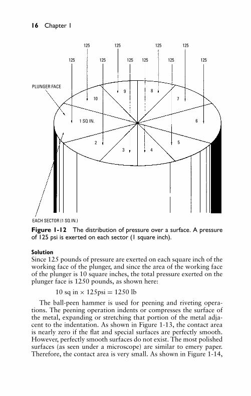
ProblemThe total working area of the plunger of a pump is 10 square inches.What is the amount of pressure on the plunger when pumpingagainst 125 psi (see Figure 1-12)?
P1: FCH
GB098-01 GB098-Miller September 13, 2004 17:28 Char Count= 0
16 Chapter 1
EACH SECTOR (1 SQ IN.)
PLUNGER FACE
1 SQ IN.
125 125 125 125
125125125125125125
10
9 8
7
6
5
43
2
Figure 1-12 The distribution of pressure over a surface. A pressureof 125 psi is exerted on each sector (1 square inch).
SolutionSince 125 pounds of pressure are exerted on each square inch of theworking face of the plunger, and since the area of the working faceof the plunger is 10 square inches, the total pressure exerted on theplunger face is 1250 pounds, as shown here:
10 sq in × 125psi = 1250 lb
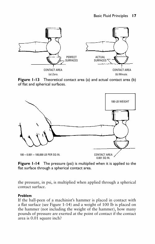
The ball-peen hammer is used for peening and riveting opera-tions. The peening operation indents or compresses the surface ofthe metal, expanding or stretching that portion of the metal adja-cent to the indentation. As shown in Figure 1-13, the contact areais nearly zero if the flat and special surfaces are perfectly smooth.However, perfectly smooth surfaces do not exist. The most polishedsurfaces (as seen under a microscope) are similar to emery paper.Therefore, the contact area is very small. As shown in Figure 1-14,
P1: FCH
GB098-01 GB098-Miller September 13, 2004 17:28 Char Count= 0
Basic Fluid Principles 17
PERFECTSURFACES
ACTUALSURFACES
(a) Zero. (b) Minute.CONTACT AREA CONTACT AREA
Figure 1-13 Theoretical contact area (a) and actual contact area (b)of flat and spherical surfaces.
100-LB WEIGHT
CONTACT AREA0.001 SQ IN.
100 ÷ 0.001 = 100,000 LB PER SQ IN.
Figure 1-14 The pressure (psi) is multiplied when it is applied to theflat surface through a spherical contact area.
the pressure, in psi, is multiplied when applied through a sphericalcontact surface.
ProblemIf the ball-peen of a machinist’s hammer is placed in contact witha flat surface (see Figure 1-14) and a weight of 100 lb is placed onthe hammer (not including the weight of the hammer), how manypounds of pressure are exerted at the point of contact if the contactarea is 0.01 square inch?
P1: FCH
GB098-01 GB098-Miller September 13, 2004 17:28 Char Count= 0
18 Chapter 1
SolutionIf the contact area were 1 square inch in area, the pressure wouldequal 100 pounds on the 1 square inch of flat surface. Now, if theentire 100-pound weight or pressure is borne on only 0.01 squareinch (see Figure 1-14), the pressure in psi is equal to 10,000 psi(100 ÷ 0.01).
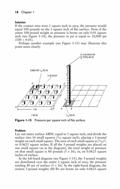
Perhaps another example (see Figure 1-15) may illustrate thispoint more clearly.
5 LB EACH ORTOTAL 80 LB
0.0625 OR 1/16 SQ IN.
5 LB EACH
1 SQ IN. 1/16 SQ IN.
1 IN.
1 IN.
AA
D
D
C
C
B B
Figure 1-15 Pressure per square inch of flat surface.
ProblemLay out entire surface ABDC equal to 1 square inch, and divide thesurface into 16 small squares (1/16 square inch), placing a 5-poundweight on each small square. The area of each small square is (1/16)2,or 0.0625 square inches. If all the 5-pound weights are placed onone small square (as in the diagram), the total weight or pressureon that small square is 80 pounds (5 × 16), or, on 0.0625 squareinches of surface.
In the left-hand diagram (see Figure 1-15), the 5-pound weightsare distributed over the entire 1 square inch of area, the pressuretotaling 80 psi of surface (5 × 16). In the right-hand diagram, thesixteen 5-pound weights (80 lb) are borne on only 0.0625 square
P1: FCH
GB098-01 GB098-Miller September 13, 2004 17:28 Char Count= 0
Basic Fluid Principles 19
inches of surface. This means the total weight or pressure (if each ofthe sixteen small squares were to bear 80 pounds) would be 1280 psiof surface (16 × 80).
Atmospheric PressureUnless stated otherwise, the term pressure indicates pressure psi. Thevarious qualifications of pressure are initial pressure, mean effectivepressure, terminal pressure, backpressure, and total pressure.
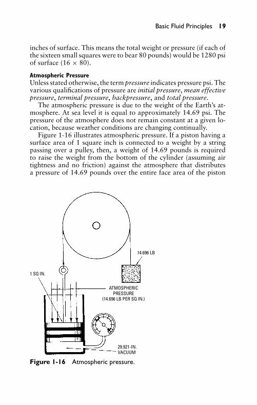
The atmospheric pressure is due to the weight of the Earth’s at-mosphere. At sea level it is equal to approximately 14.69 psi. Thepressure of the atmosphere does not remain constant at a given lo-cation, because weather conditions are changing continually.
Figure 1-16 illustrates atmospheric pressure. If a piston having asurface area of 1 square inch is connected to a weight by a stringpassing over a pulley, then, a weight of 14.69 pounds is requiredto raise the weight from the bottom of the cylinder (assuming airtightness and no friction) against the atmosphere that distributesa pressure of 14.69 pounds over the entire face area of the piston
1 SQ IN.
14.696 LB
29.921-IN.VACUUM
ATMOSPHERICPRESSURE
(14.696 LB PER SQ IN.)
Figure 1-16 Atmospheric pressure.
P1: FCH
GB098-01 GB098-Miller September 13, 2004 17:28 Char Count= 0
20 Chapter 1
(area = 1 square inch). Then the system is in a state of equilibrium,the weight balancing the resistance or weight of the atmosphere. Aslight excess pressure is then required to move the piston.
Atmospheric pressure decreases approximately 0.5 pounds foreach 1000-foot increase in elevation. When an automobile climbsa high mountain, the engine gradually loses power because air ex-pands at higher altitudes. The volume of air taken in by the enginedoes not weigh as much at the higher altitudes as it weighs at sealevel. The mixture becomes too rich at higher altitudes, causing apoor combustion of fuel.
A perfect vacuum is a space that has no matter in it. This isunattainable even with the present pumps and chemical processes.Space in which the air pressure is about one-thousandth of that ofthe atmosphere is generally called a vacuum. Partial vacuum hasbeen obtained in which there are only a few billion molecules ineach cubic inch. In normal air, there are about four hundred billiontimes a billion molecules of gas to each cubic inch.
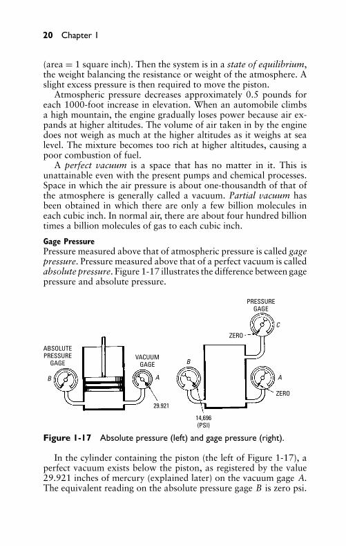
Gage PressurePressure measured above that of atmospheric pressure is called gagepressure. Pressure measured above that of a perfect vacuum is calledabsolute pressure. Figure 1-17 illustrates the difference between gagepressure and absolute pressure.
ABSOLUTEPRESSURE
GAGEVACUUM
GAGE
PRESSUREGAGE
ZERO
ZERO
29.921
A AB
B
C
14,696(PSI)
Figure 1-17 Absolute pressure (left) and gage pressure (right).
In the cylinder containing the piston (the left of Figure 1-17), aperfect vacuum exists below the piston, as registered by the value29.921 inches of mercury (explained later) on the vacuum gage A.The equivalent reading on the absolute pressure gage B is zero psi.
P1: FCH
GB098-01 GB098-Miller September 13, 2004 17:28 Char Count= 0
Basic Fluid Principles 21
If the piston is removed from the cylinder (the right of Figure 1-17),air rushes into the cylinder. That is, the vacuum is replaced by air atatmospheric pressure, the vacuum gage A drops to zero, the absolutepressure gage B reads 14.696, and the pressure gage C indicates agage pressure of zero.
BarometerA barometer is an instrument that is used to measure atmosphericpressure. The instrument can be used to determine height or altitudeabove sea level, and it can be used in forecasting weather.
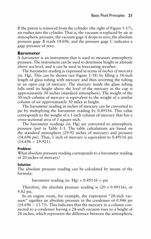
The barometer reading is expressed in terms of inches of mercury(in. Hg). This can be shown (see Figure 1-18) by filling a 34-inchlength of glass tubing with mercury and then inverting the tubingin an open cup of mercury. The mercury inside the glass tubingfalls until its height above the level of the mercury in the cup isapproximately 30 inches (standard atmosphere). The weight of the30-inch column of mercury is equivalent to the weight of a similarcolumn of air approximately 50 miles in height.
The barometer reading in inches of mercury can be converted topsi by multiplying the barometer reading by 0.49116. This valuecorresponds to the weight of a 1-inch column of mercury that has across-sectional area of 1 square inch.
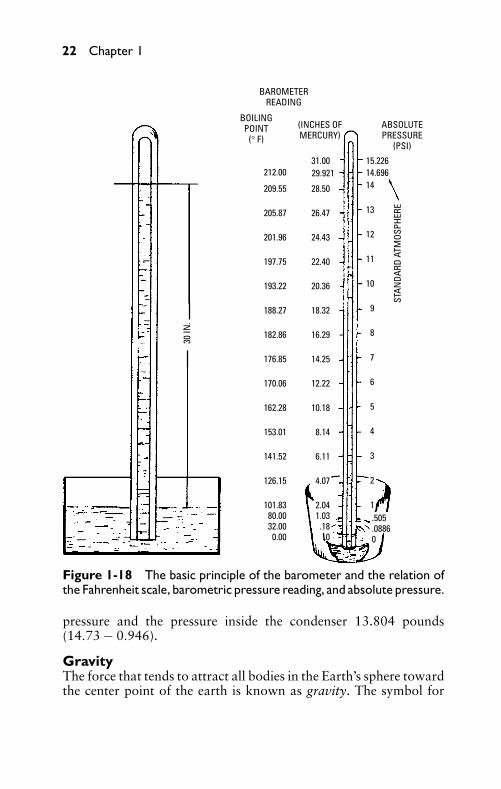
The barometer readings (in. Hg) are converted to atmosphericpressure (psi) in Table 1-3. The table calculations are based onthe standard atmosphere (29.92 inches of mercury) and pressure(14.696 psi). Thus, 1 inch of mercury is equivalent to 0.49116 psi(14.696 ÷ 29.921).
ProblemWhat absolute pressure reading corresponds to a barometer readingof 20 inches of mercury?
SolutionThe absolute pressure reading can be calculated by means of theformula:
barometer reading (in. Hg) × 0.49116 = psi
Therefore, the absolute pressure reading is (20 × 0.49116), or9.82 psi.
In an engine room, for example, the expression “28-inch vac-uum” signifies an absolute pressure in the condenser of 0.946 psi(14.696 − 13.75). This indicates that the mercury in a column con-nected to a condenser having a 28-inch vacuum rises to a height of28 inches, which represents the difference between the atmospheric
P1: FCH
GB098-01 GB098-Miller September 13, 2004 17:28 Char Count= 0
22 Chapter 1
BAROMETERREADING
BOILINGPOINT
(° F)
(INCHES OFMERCURY)
ABSOLUTEPRESSURE
(PSI)
212.00
209.55
205.87
201.96
197.75
193.22
188.27
182.86
176.85
170.06
162.28
153.01
141.52
126.15
101.8380.0032.00
0.00
31.00
28.50
26.47
24.43
22.40
20.36
18.32
16.29
14.25
12.22
10.18
8.14
6.11
4.07
2.041.03
.180
15.22614.69629.92114
13
12
11
10
9
8
7
6
5
4
3
2
1.505.08860
STAN
DARD
ATM
OSPH
ERE
30 IN
.
Figure 1-18 The basic principle of the barometer and the relation ofthe Fahrenheit scale, barometric pressure reading, and absolute pressure.
pressure and the pressure inside the condenser 13.804 pounds(14.73 − 0.946).
GravityThe force that tends to attract all bodies in the Earth’s sphere towardthe center point of the earth is known as gravity. The symbol for
P1: FCH
GB098-01 GB098-Miller September 13, 2004 17:28 Char Count= 0
Basic Fluid Principles 23
Table 1-3 Conversion of Barometer Reading to AbsolutePressure
Barometer (in. Hg) Pressure (psi)
28.00 13.7528.25 13.8828.50 14.0028.75 14.1229.00 14.2429.25 14.3729.50 14.4929.75 14.6129.921 14.69630.00 14.7430.25 14.8630.50 14.9830.75 15.1031.00 15.23
gravity is g . The rate of acceleration of gravity is 32.16 feet persecond. Starting from a state of rest, a free-falling body falls 32.16feet during the first second; at the end of the next second, the bodyis falling at a velocity of 64.32 feet per second (32.16 + 32.16).
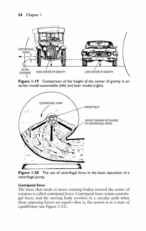
Center of GravityThat point in a body about which all its weight or parts are evenlydistributed or balanced is known as its center of gravity (abbreviatedc.g .). If the body is supported at its center of gravity, the entire bodyremains at rest, even though it is attracted by gravity. A higher centerof gravity and a lower center of gravity are compared in Figure 1-19,as related to the center of gravity in automobiles.
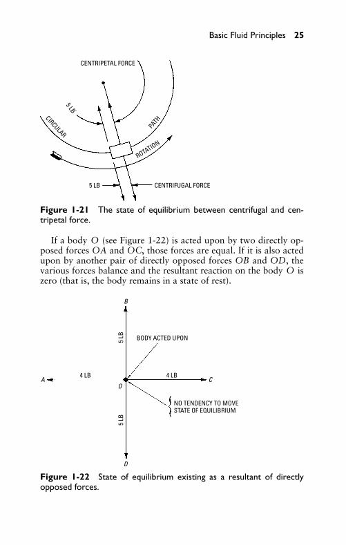
Centrifugal ForceThe force that tends to move rotating bodies away from the centerof rotation is called centrifugal force. It is caused by inertia. A bodymoving in a circular path tends to be forced farther from the axis(or center point) of the circle described by its path.
If the centrifugal force balances the attraction of the mass aroundwhich it revolves, the body continues to move in a uniform path.The operating principle of the centrifugal pump (see Figure 1-20) isbased on centrifugal force.
P1: FCH
GB098-01 GB098-Miller September 13, 2004 17:28 Char Count= 0
24 Chapter 1
CENTRIFUGALFORCE
EXTRALEVERAGE HIGH CENTER OF GRAVITY LOW CENTER OF GRAVITY
Figure 1-19 Comparison of the height of the center of gravity in anearlier model automobile (left) and later model (right).
CENTRIFUGAL PUMPWATER INLET
WATER THROWN OFF BLADESBY CENTRIFUGAL FORCE
Figure 1-20 The use of centrifugal force in the basic operation of acentrifugal pump.
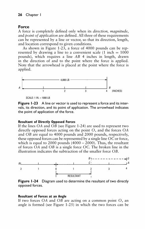
Centripetal ForceThe force that tends to move rotating bodies toward the center ofrotation is called centripetal force. Centripetal force resists centrifu-gal force, and the moving body revolves in a circular path whenthese opposing forces are equal—that is, the system is in a state ofequilibrium (see Figure 1-21).
P1: FCH
GB098-01 GB098-Miller September 13, 2004 17:28 Char Count= 0
Basic Fluid Principles 25
CENTRIPETAL FORCE
CENTRIFUGAL FORCE5 LB
5 LB
PATH
CIRCULAR
ROTATION
Figure 1-21 The state of equilibrium between centrifugal and cen-tripetal force.
If a body O (see Figure 1-22) is acted upon by two directly op-posed forces OA and OC, those forces are equal. If it is also actedupon by another pair of directly opposed forces OB and OD, thevarious forces balance and the resultant reaction on the body O iszero (that is, the body remains in a state of rest).
BODY ACTED UPON
NO TENDENCY TO MOVESTATE OF EQUILIBRIUM
4 LB 4 LB
5 LB
5 LB
A
B
C
D
O
Figure 1-22 State of equilibrium existing as a resultant of directlyopposed forces.
P1: FCH
GB098-01 GB098-Miller September 13, 2004 17:28 Char Count= 0
26 Chapter 1
ForceA force is completely defined only when its direction, magnitude,and point of application are defined. All three of these requirementscan be represented by a line or vector, so that its direction, length,and location correspond to given conditions.
As shown in Figure 1-23, a force of 4000 pounds can be rep-resented by drawing a line to a convenient scale (1 inch = 1000pounds), which requires a line AB 4 inches in length, drawnin the direction of and to the point where the force is applied.Note that the arrowhead is placed at the point where the force isapplied.
4,000 LB
1 2 3 4 (INCHES)A B
SCALE: 1 IN. = 1000 LB
Figure 1-23 A line or vector is used to represent a force and its inter-vals, its direction, and its point of application. The arrowhead indicatesthe point of application of the force.
Resultant of Directly Opposed ForcesIf the lines OA and OB (see Figure 1-24) are used to represent twodirectly opposed forces acting on the point O, and the forces OAand OB are equal to 4000 pounds and 2000 pounds, respectively,these opposed forces can be represented by a single line OC or force,which is equal to 2000 pounds (4000 – 2000). Thus, the resultantof forces OA and OB is a single force OC. The broken line in theillustration indicates the subtraction of the smaller force OB.
B
B
AO
C
RESULTANT
2 1 0 1 2 3 4
Figure 1-24 Diagram used to determine the resultant of two directlyopposed forces.
Resultant of Forces at an AngleIf two forces OA and OB are acting on a common point O, anangle is formed (see Figure 1-25) in which the two forces can be
P1: FCH
GB098-01 GB098-Miller September 13, 2004 17:28 Char Count= 0
Basic Fluid Principles 27
B
O A
φ
Figure 1-25 Diagram of two forces acting on a common point at anangle to each other.
represented by the lines OA and OB whose lengths represent 4000pounds and 2000 pounds, respectively.
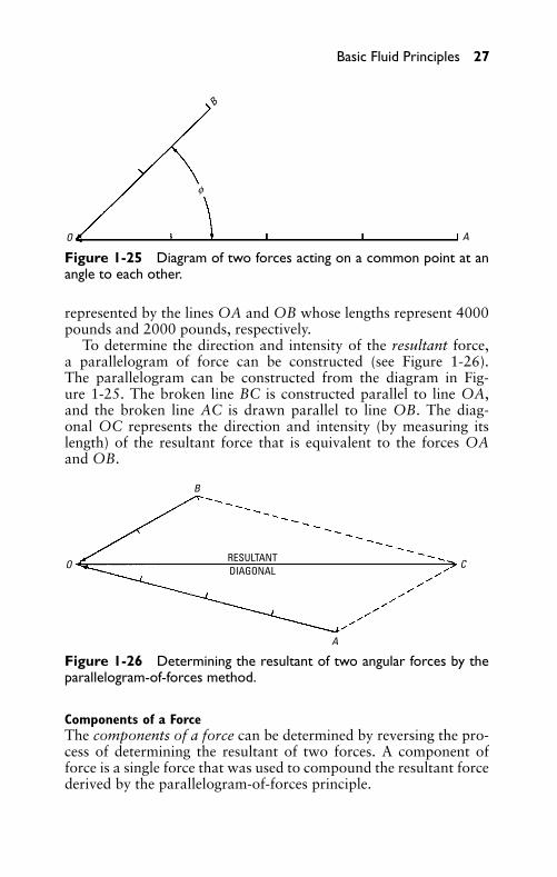
To determine the direction and intensity of the resultant force,a parallelogram of force can be constructed (see Figure 1-26).The parallelogram can be constructed from the diagram in Fig-ure 1-25. The broken line BC is constructed parallel to line OA,and the broken line AC is drawn parallel to line OB. The diag-onal OC represents the direction and intensity (by measuring itslength) of the resultant force that is equivalent to the forces OAand OB.
B
A
CORESULTANTDIAGONAL
Figure 1-26 Determining the resultant of two angular forces by theparallelogram-of-forces method.
Components of a ForceThe components of a force can be determined by reversing the pro-cess of determining the resultant of two forces. A component offorce is a single force that was used to compound the resultant forcederived by the parallelogram-of-forces principle.

P1: FCH
GB098-01 GB098-Miller September 13, 2004 17:28 Char Count= 0
28 Chapter 1
For example, the reaction caused by the thrust of a connectingrod on the crank pin (see Figure 1-27) may be considered. The thrustcan be divided into two component forces.
DELIVERS TURNING EFFECT
COMPONENTSTANGENTIAL
AXIAL
DELIVERS PRESSUREON BEARING; USELESS
CONNECTING
ROD
AXIS
A
C
B
O
Figure 1-27 Determining the components of a force by means of theparallelogram-of-forces method.
One component force acts in a direction tangent to the circledescribed by the crank pin, which causes the crank to turn. Theother component force acts in the direction of the axis of the crankarm, which causes the shaft to press against its bearing. A diagram(see Figure 1-27) can be constructed to determine the componentsof a force.
From point O, project a line OC equal in length to the thrust ofthe connecting rod (see Figure 1-27). Complete the parallelogramof forces to obtain points B and A, their lengths OB and OA rep-resenting the components of force in direction and intensity.
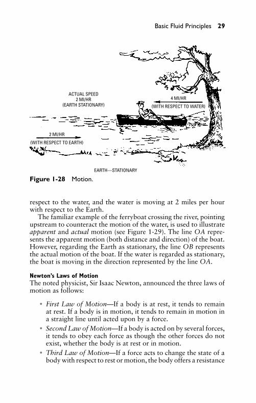
MotionMotion is usually described as a change in position in relation toan assumed fixed point. Motion is strictly a relative matter becausethere can be no motion unless some point or object is regarded asstationary (see Figure 1-28).
As shown in Figure 1-28, the man is rowing the boat at a speedof 4 miles per hour against a current flowing at 2 miles per hour inthe opposite direction. The boat is moving at 4 miles per hour with
P1: FCH
GB098-01 GB098-Miller September 13, 2004 17:28 Char Count= 0
Basic Fluid Principles 29
EARTH—STATIONARY
ACTUAL SPEED2 MI/HR
(EARTH STATIONARY)4 MI/HR
(WITH RESPECT TO WATER)
2 MI/HR
(WITH RESPECT TO EARTH)
Figure 1-28 Motion.
respect to the water, and the water is moving at 2 miles per hourwith respect to the Earth.
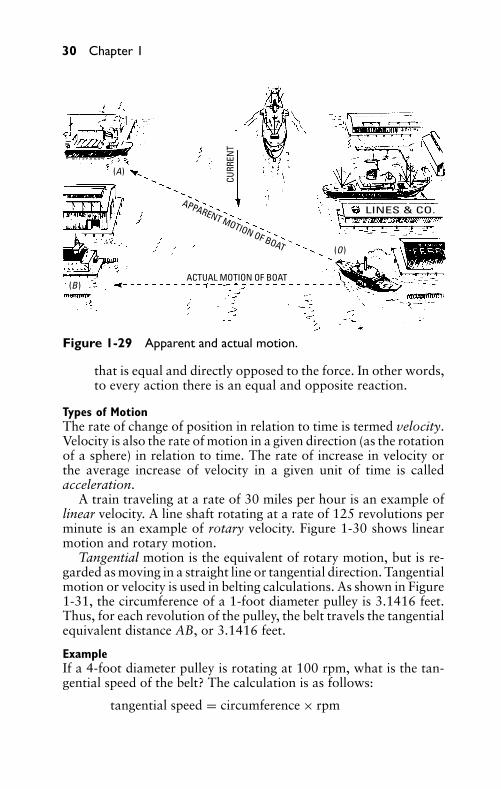
The familiar example of the ferryboat crossing the river, pointingupstream to counteract the motion of the water, is used to illustrateapparent and actual motion (see Figure 1-29). The line OA repre-sents the apparent motion (both distance and direction) of the boat.However, regarding the Earth as stationary, the line OB representsthe actual motion of the boat. If the water is regarded as stationary,the boat is moving in the direction represented by the line OA.
Newton’s Laws of MotionThe noted physicist, Sir Isaac Newton, announced the three laws ofmotion as follows:
� First Law of Motion—If a body is at rest, it tends to remainat rest. If a body is in motion, it tends to remain in motion ina straight line until acted upon by a force.
� Second Law of Motion—If a body is acted on by several forces,it tends to obey each force as though the other forces do notexist, whether the body is at rest or in motion.
� Third Law of Motion—If a force acts to change the state of abody with respect to rest or motion, the body offers a resistance
P1: FCH
GB098-01 GB098-Miller September 13, 2004 17:28 Char Count= 0
30 Chapter 1
CURR
ENT
APPARENT MOTION OF BOAT
ACTUAL MOTION OF BOAT
(A)
(B)
(O)
LINES & CO.
Figure 1-29 Apparent and actual motion.
that is equal and directly opposed to the force. In other words,to every action there is an equal and opposite reaction.
Types of MotionThe rate of change of position in relation to time is termed velocity.Velocity is also the rate of motion in a given direction (as the rotationof a sphere) in relation to time. The rate of increase in velocity orthe average increase of velocity in a given unit of time is calledacceleration.
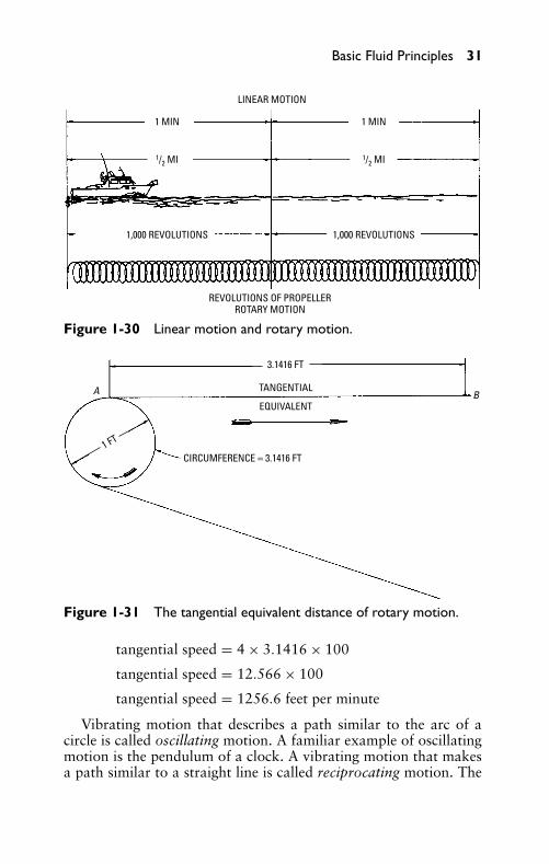
A train traveling at a rate of 30 miles per hour is an example oflinear velocity. A line shaft rotating at a rate of 125 revolutions perminute is an example of rotary velocity. Figure 1-30 shows linearmotion and rotary motion.
Tangential motion is the equivalent of rotary motion, but is re-garded as moving in a straight line or tangential direction. Tangentialmotion or velocity is used in belting calculations. As shown in Figure1-31, the circumference of a 1-foot diameter pulley is 3.1416 feet.Thus, for each revolution of the pulley, the belt travels the tangentialequivalent distance AB, or 3.1416 feet.
ExampleIf a 4-foot diameter pulley is rotating at 100 rpm, what is the tan-gential speed of the belt? The calculation is as follows:
tangential speed = circumference × rpm
P1: FCH
GB098-01 GB098-Miller September 13, 2004 17:28 Char Count= 0
Basic Fluid Principles 31
LINEAR MOTION
1 MIN
1/2 MI
1 MIN
1/2 MI
1,000 REVOLUTIONS 1,000 REVOLUTIONS
REVOLUTIONS OF PROPELLERROTARY MOTION
Figure 1-30 Linear motion and rotary motion.
A B
1 FT
3.1416 FT
TANGENTIAL
EQUIVALENT
CIRCUMFERENCE = 3.1416 FT
Figure 1-31 The tangential equivalent distance of rotary motion.
tangential speed = 4 × 3.1416 × 100
tangential speed = 12.566 × 100
tangential speed = 1256.6 feet per minute
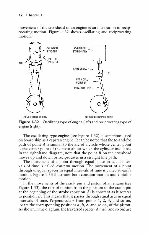
Vibrating motion that describes a path similar to the arc of acircle is called oscillating motion. A familiar example of oscillatingmotion is the pendulum of a clock. A vibrating motion that makesa path similar to a straight line is called reciprocating motion. The
P1: FCH
GB098-01 GB098-Miller September 13, 2004 17:28 Char Count= 0
32 Chapter 1
movement of the crosshead of an engine is an illustration of recip-rocating motion. Figure 1-32 shows oscillating and reciprocatingmotion.
ARC
CYLINDERPIVOTED
CYLINDERSTATIONARY
PATH OFPOINT A
CROSSHEAD
PATH OFPOINT B
STRAIGHT LINE
B
A
(A) Oscillating engine. (B) Reciprocating engine.
Figure 1-32 Oscillating type of engine (left) and reciprocating type ofengine (right).
The oscillating-type engine (see Figure 1-32) is sometimes usedon board ship as a capstan engine. It can be noted that the to-and-fropath of point A is similar to the arc of a circle whose center pointis the center point of the pivot about which the cylinder oscillates.In the right-hand diagram, note that the point B on the crossheadmoves up and down or reciprocates in a straight line path.
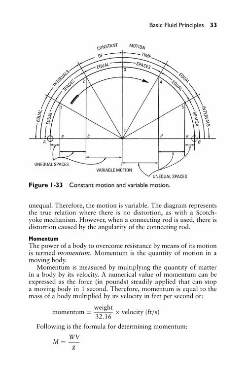
The movement of a point through equal space in equal inter-vals of time is called constant motion. The movement of a pointthrough unequal spaces in equal intervals of time is called variablemotion. Figure 1-33 illustrates both constant motion and variablemotion.
In the movements of the crank pin and piston of an engine (seeFigure 1-33), the rate of motion from the position of the crank pinat the beginning of the stroke (position A) is constant as it rotatesto position B. This means that it passes through equal arcs in equalintervals of time. Perpendiculars from points 1, 2, 3, and so on,locate the corresponding positions a , b, c, and so on, of the piston.As shown in the diagram, the traversed spaces (Aa, ab, and so on) are
P1: FCH
GB098-01 GB098-Miller September 13, 2004 17:28 Char Count= 0
Basic Fluid Principles 33
EQUA
L
EQUA
L
INTERVALS
SPACES
EQUALEQUAL
INTERVALS
SPACESTIME
SPACES
OF
EQUAL
UNEQUAL SPACES
UNEQUAL SPACESVARIABLE MOTION
A Ba b
cd e
1
2
3
4
5
CONSTANT MOTION
Figure 1-33 Constant motion and variable motion.
unequal. Therefore, the motion is variable. The diagram representsthe true relation where there is no distortion, as with a Scotch-yoke mechanism. However, when a connecting rod is used, there isdistortion caused by the angularity of the connecting rod.
MomentumThe power of a body to overcome resistance by means of its motionis termed momentum. Momentum is the quantity of motion in amoving body.
Momentum is measured by multiplying the quantity of matterin a body by its velocity. A numerical value of momentum can beexpressed as the force (in pounds) steadily applied that can stopa moving body in 1 second. Therefore, momentum is equal to themass of a body multiplied by its velocity in feet per second or:
momentum = weight32.16
× velocity (ft/s)
Following is the formula for determining momentum:
M = WVg
P1: FCH
GB098-01 GB098-Miller September 13, 2004 17:28 Char Count= 0
34 Chapter 1
in which the following is true:
W is the weight (in pounds)V is velocity (in feet per second)g is attraction caused by gravity (32.16)
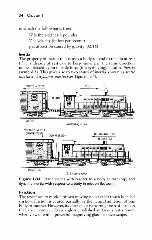
InertiaThe property of matter that causes a body to tend to remain at rest(if it is already at rest); or to keep moving in the same directionunless affected by an outside force (if it is moving), is called inertia(symbol I ). This gives rise to two states of inertia known as staticinertia and dynamic inertia (see Figure 1-34).
STATIC INERTIA
TENSION
PULL
AT REST
DYNAMIC INERTIA(MOMENTUM)
COMPRESSION
IN MOTION
RETARDING FORCE
(BRAKE ON)
(A) Starting action.
(B) Stopping action.
Figure 1-34 Static inertia with respect to a body at rest (top) anddynamic inertia with respect to a body in motion (bottom).
FrictionThe resistance to motion of two moving objects that touch is calledfriction. Friction is caused partially by the natural adhesion of onebody to another. However, its chief cause is the roughness of surfacesthat are in contact. Even a glossy, polished surface is not smoothwhen viewed with a powerful magnifying glass or microscope.
P1: FCH
GB098-01 GB098-Miller September 13, 2004 17:28 Char Count= 0
Basic Fluid Principles 35
Coefficient of FrictionThe ratio of the force required to slide a body along a horizontalplane surface to the weight of the body is the coefficient of friction.The coefficient of friction is equivalent to the tangent of the angleof repose.
The angle of repose is the largest angle with the horizontal atwhich a mass of material (such as an embankment or pile of coal)can remain at rest without sliding. This angle varies with differentmaterials.
Laws of FrictionThe first laws of friction were given by Morin in about 1830, butthey have been modified by later experiments. As summarized byKent, the laws of friction are as follows:
� Friction varies approximately as the normal pressure withwhich the rubbing surfaces are pressed together.
� Friction is approximately independent of the area of the sur-faces, but it is slightly greater for smaller surfaces than forlarger surfaces.
� Friction decreases with an increase in velocity, except at anextremely low velocity and with soft surfaces.
As applied to lubricated surfaces, the laws of friction for perfectlubrication (surfaces completely separated by a film of lubricant) areas follows:
� The coefficient of friction is independent of the materials mak-ing up the surfaces.
� The coefficient of friction varies directly with the viscosity ofthe lubricant, which varies inversely with the temperature ofthe lubricant.
� The coefficient of friction varies inversely as the unit pressureand varies directly as the velocity.
� The coefficient of friction varies inversely as the mean filmthickness of the lubricating medium.
� Mean film thickness varies directly with velocity and inverselyas the temperature and unit pressure.
As applied to imperfect lubrication, that is, surfaces partially sep-arated (which may range from nearly complete separation to nearlycomplete contact) by a film of lubricant, the laws of friction are as
P1: FCH
GB098-01 GB098-Miller September 13, 2004 17:28 Char Count= 0
36 Chapter 1
follows:� The coefficient of friction increases with an increase in pressure
between the surfaces.� The coefficient of friction increases with an increase in relative
velocity between the surfaces.
Machinery cannot be operated without lubrication (notwith-standing the alleged antifriction metals) because of the tiny irreg-ularities in a smooth metal surface. A lubricant is used to keep therubbing parts separated by a thin film of oil, thus preventing actualcontact so far as possible.
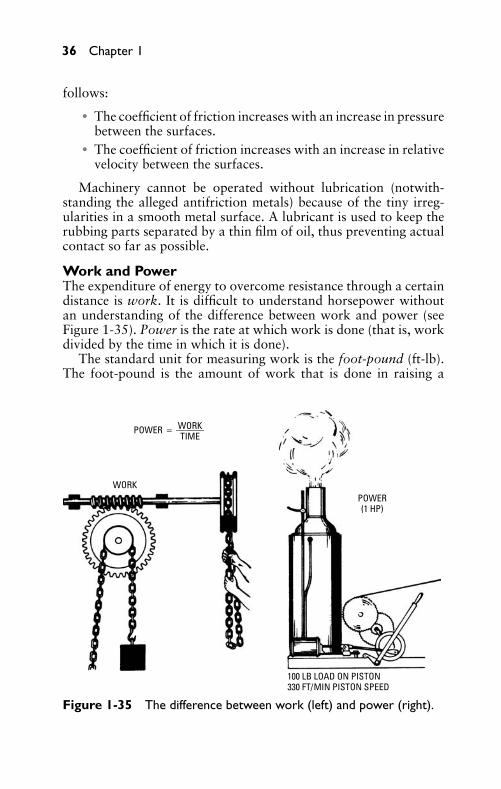
Work and PowerThe expenditure of energy to overcome resistance through a certaindistance is work. It is difficult to understand horsepower withoutan understanding of the difference between work and power (seeFigure 1-35). Power is the rate at which work is done (that is, workdivided by the time in which it is done).
The standard unit for measuring work is the foot-pound (ft-lb).The foot-pound is the amount of work that is done in raising a
POWER = ———WORKTIME
WORKPOWER(1 HP)
100 LB LOAD ON PISTON330 FT/MIN PISTON SPEED
Figure 1-35 The difference between work (left) and power (right).
P1: FCH
GB098-01 GB098-Miller September 13, 2004 17:28 Char Count= 0
Basic Fluid Principles 37
1FT-LB
1 LB
1 FT
1 2
3
4
5 6
7
8
9 1
0 1
1 1
2
1 2
3
4
5 6
7
8
9 1
0 1
1 1
2
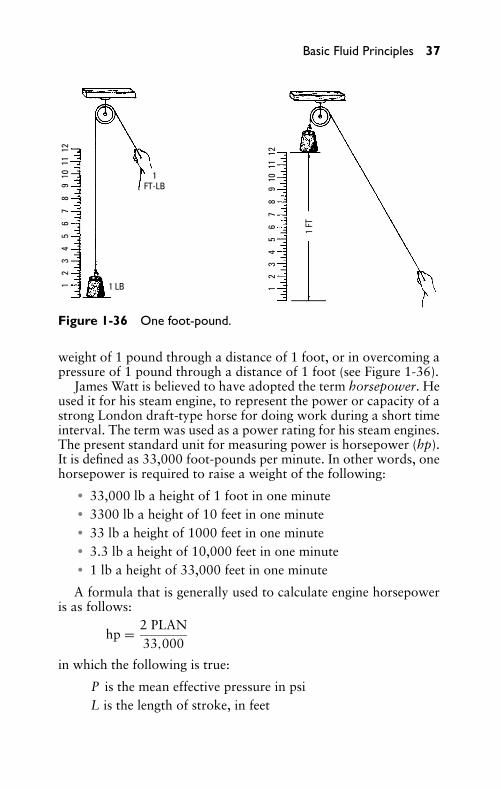
Figure 1-36 One foot-pound.
weight of 1 pound through a distance of 1 foot, or in overcoming apressure of 1 pound through a distance of 1 foot (see Figure 1-36).
James Watt is believed to have adopted the term horsepower. Heused it for his steam engine, to represent the power or capacity of astrong London draft-type horse for doing work during a short timeinterval. The term was used as a power rating for his steam engines.The present standard unit for measuring power is horsepower (hp).It is defined as 33,000 foot-pounds per minute. In other words, onehorsepower is required to raise a weight of the following:
� 33,000 lb a height of 1 foot in one minute� 3300 lb a height of 10 feet in one minute� 33 lb a height of 1000 feet in one minute� 3.3 lb a height of 10,000 feet in one minute� 1 lb a height of 33,000 feet in one minute
A formula that is generally used to calculate engine horsepoweris as follows:
hp = 2 PLAN33,000
in which the following is true:
P is the mean effective pressure in psiL is the length of stroke, in feet
P1: FCH
GB098-01 GB098-Miller September 13, 2004 17:28 Char Count= 0
38 Chapter 1
A is the area of piston, in square inches (0.7854 × d2)N is the number of revolutions per minute (rpm)
Since the stroke of an engine is usually given in inches rather thanin feet, and the revolutions per minute are given rather than the pis-ton speed, the previous formula involves extra calculations for theseitems, as well as the extra multiplication and division introduced be-cause of the constants. Therefore, the formula can be reduced to itslowest terms, as follows:
hp = 2 PLAN33,000
=2 × P × L
12× (0.7854 × d 2) × N
33,000
= 0.1309 × PLD2N33,000
= 0.000003967 PLD2N
Thus, the constant 0.000004 can be used for most calculations.By changing the order of the factors, the formula is simplified to:
hp = 0.000004 d2LNP
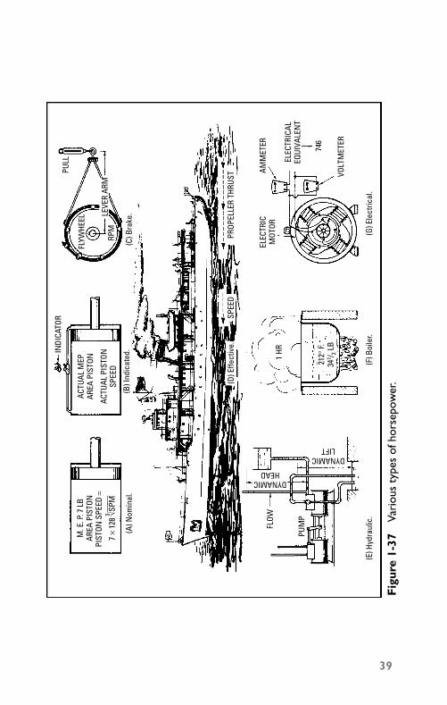
According to its definitions and the manner in which it is derived,the various types of horsepower are nominal, indicated, brake, effec-tive, hydraulic, boiler, and electrical. Figure 1-37 shows the varioustypes of horsepower.
Basic MachinesFor many years the basic mechanical contrivances that enter into thecomposition or formation of machines were referred to as mechan-ical powers. Since these mechanical contrivances are regarded in amore static than dynamic sense (that is, the consideration of oppos-ing forces in equilibrium rather than tending to produce motion), itis more correct to refer to them as basic machines. Strictly speaking,the term power is a dynamic term relating to the time rate of doingwork. When the elements of a machine are in equilibrium, no workis done. Therefore, it is incorrect to refer to the basic machines asmechanical powers.
It should be understood that the action of all the basic machinesdepends on the principle of work, which is: The applied force,
P1: FCH
GB098-01 GB098-Miller September 13, 2004 17:28 Char Count= 0
M. E
. P. 7
LB
AREA
PIS
TON
PIST
ON S
PEED
=
7 ×
128
3 √ SP M
ACTU
AL M
EPAR
EA P
ISTO
N
ACTU
AL P
ISTO
NSP
EED
INDI
CATO
R
FLYW
HEEL
RPM
PULL
LEVE
R AR
M
(D) E
ffect
ive.
SPEE
DPR
OPEL
LER
THRU
ST
FLOW
PUM
P
DYNAMICHEAD
DYNAMICLIFT
1 HR
212°
F.34
1 / 2 LB
ELEC
TRIC
MOT
ORAM
MET
ER
VOLT
MET
ER
746
ELEC
TRIC
ALEQ
UIVA
LEN
T
(A) N
omin
al.
(C) B
rake
.(B
) Ind
icat
ed.
(E) H
ydra
ulic
.(F
) Boi
ler.
(G) E
lect
rical
.
Fig
ure
1-37
Vari
ous
type
sof
hors
epow
er.
39
P1: FCH
GB098-01 GB098-Miller September 13, 2004 17:28 Char Count= 0
40 Chapter 1
multiplied by the distance through which it moves, equals the re-sistance overcome, multiplied by the distance through which it isovercome.
Following are the basic machine:
� Lever� Wheel and axle� Pulley� Inclined plane� Screw� Wedge
These machines can be reduced further to three classes of ma-chines, as follows:
� A solid body turning on an axis� A flexible cord� A hard and smooth inclined surface
The Principle of Moments is important in studying the basic ma-chines. This important principle can be stated as follows: “Whentwo or more forces act on a rigid body and tend to turn it on anaxis, equilibrium exists if the sum of the moments of the forceswhich tend to turn the body in one direction equals the sum of themoments of those forces which tend to turn the body in the oppositedirection about the same axis.
LeverA lever is a bar of metal, wood, or other substance that is used toexert a pressure or to sustain a weight at one point in its length byreceiving a force at a second point, and is free to turn at a thirdor fixed point called the fulcrum. Its application is based on thePrinciple of Moments. The following general rule can be applied toall classes of levers.
Rule: The force P , multiplied by its distance from the fulcrum F,is equal to the load W, multiplied by its distance from the fulcrum.
Thus, the formula for calculation involving the three classes oflevers is:
F × distance = W × distance
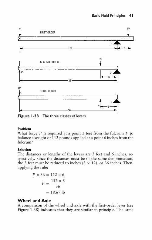
As shown in Figure 1-38, there are three classes of levers.
P1: FCH
GB098-01 GB098-Miller September 13, 2004 17:28 Char Count= 0
Basic Fluid Principles 41
FIRST ORDER
SECOND ORDER
THIRD ORDER
36
36
36
6
6
6
P
P
P
W
W
W
F
F
F
Figure 1-38 The three classes of levers.
ProblemWhat force P is required at a point 3 feet from the fulcrum F tobalance a weight of 112 pounds applied at a point 6 inches from thefulcrum?
SolutionThe distances or lengths of the levers are 3 feet and 6 inches, re-spectively. Since the distances must be of the same denomination,the 3 feet must be reduced to inches (3 × 12), or 36 inches. Then,applying the rule:
P × 36 = 112 × 6
P = 112 × 636
= 18.67 lb
Wheel and AxleA comparison of the wheel and axle with the first-order lever (seeFigure 1-38) indicates that they are similar in principle. The same
P1: FCH
GB098-01 GB098-Miller September 13, 2004 17:28 Char Count= 0
42 Chapter 1
A B
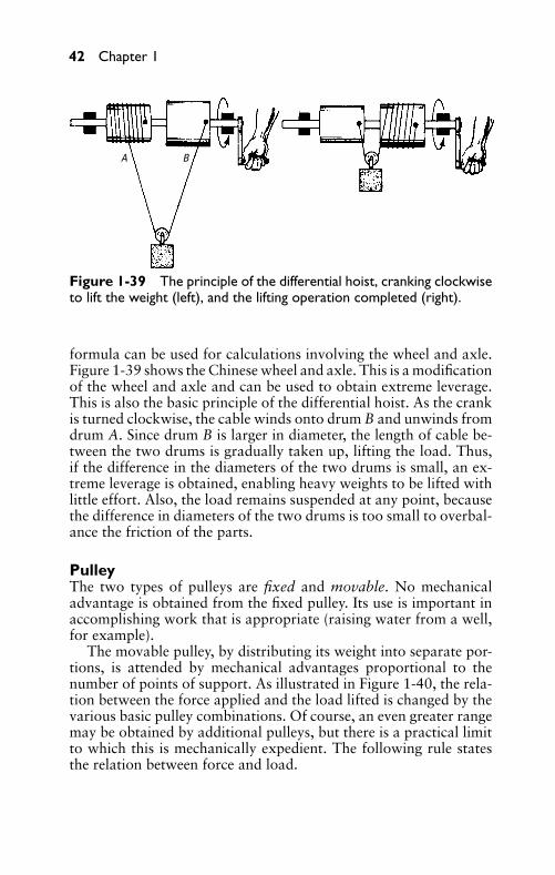
Figure 1-39 The principle of the differential hoist, cranking clockwiseto lift the weight (left), and the lifting operation completed (right).
formula can be used for calculations involving the wheel and axle.Figure 1-39 shows the Chinese wheel and axle. This is a modificationof the wheel and axle and can be used to obtain extreme leverage.This is also the basic principle of the differential hoist. As the crankis turned clockwise, the cable winds onto drum B and unwinds fromdrum A. Since drum B is larger in diameter, the length of cable be-tween the two drums is gradually taken up, lifting the load. Thus,if the difference in the diameters of the two drums is small, an ex-treme leverage is obtained, enabling heavy weights to be lifted withlittle effort. Also, the load remains suspended at any point, becausethe difference in diameters of the two drums is too small to overbal-ance the friction of the parts.
PulleyThe two types of pulleys are fixed and movable. No mechanicaladvantage is obtained from the fixed pulley. Its use is important inaccomplishing work that is appropriate (raising water from a well,for example).
The movable pulley, by distributing its weight into separate por-tions, is attended by mechanical advantages proportional to thenumber of points of support. As illustrated in Figure 1-40, the rela-tion between the force applied and the load lifted is changed by thevarious basic pulley combinations. Of course, an even greater rangemay be obtained by additional pulleys, but there is a practical limitto which this is mechanically expedient. The following rule statesthe relation between force and load.
P1: FCH
GB098-01 GB098-Miller September 13, 2004 17:28 Char Count= 0
Basic Fluid Principles 43
W1
W2
W3
W4 W5 W6 W7
F1
F1F1
F1 F1
F1
F1
1
1 1 122
3
1 2 3 4 1 2 3 4 51 2
33
4 5 61 2 4 5 6 7
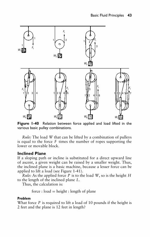
Figure 1-40 Relation between force applied and load lifted in thevarious basic pulley combinations.
Rule: The load W that can be lifted by a combination of pulleysis equal to the force F times the number of ropes supporting thelower or movable block.
Inclined PlaneIf a sloping path or incline is substituted for a direct upward lineof ascent, a given weight can be raised by a smaller weight. Thus,the inclined plane is a basic machine, because a lesser force can beapplied to lift a load (see Figure 1-41).
Rule: As the applied force P is to the load W, so is the height Hto the length of the inclined plane L.
Thus, the calculation is:
force : load = height : length of plane
ProblemWhat force P is required to lift a load of 10 pounds if the height is2 feet and the plane is 12 feet in length?
P1: FCH
GB098-01 GB098-Miller September 13, 2004 17:28 Char Count= 0
44 Chapter 1
PULLEY
LOAD INCLINEDPLANE
P/W = H/L
PH L
W
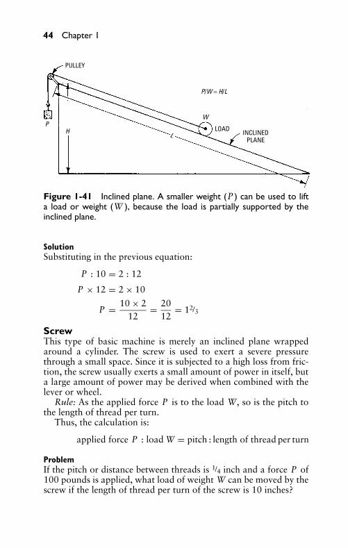
Figure 1-41 Inclined plane. A smaller weight (P ) can be used to lifta load or weight (W ), because the load is partially supported by theinclined plane.
SolutionSubstituting in the previous equation:
P : 10 = 2 : 12
P × 12 = 2 × 10
P = 10 × 212
= 2012
= 12/3
ScrewThis type of basic machine is merely an inclined plane wrappedaround a cylinder. The screw is used to exert a severe pressurethrough a small space. Since it is subjected to a high loss from fric-tion, the screw usually exerts a small amount of power in itself, buta large amount of power may be derived when combined with thelever or wheel.
Rule: As the applied force P is to the load W, so is the pitch tothe length of thread per turn.
Thus, the calculation is:
applied force P : load W = pitch : length of thread per turn
ProblemIf the pitch or distance between threads is 1/4 inch and a force P of100 pounds is applied, what load of weight W can be moved by thescrew if the length of thread per turn of the screw is 10 inches?
P1: FCH
GB098-01 GB098-Miller September 13, 2004 17:28 Char Count= 0
Basic Fluid Principles 45
SolutionSubstituting in the above equation:
100 : load W = 1/4 : 10
load W × 1/4 = 10 × 100
load W = 10 × 1001/4
= 4000 lb
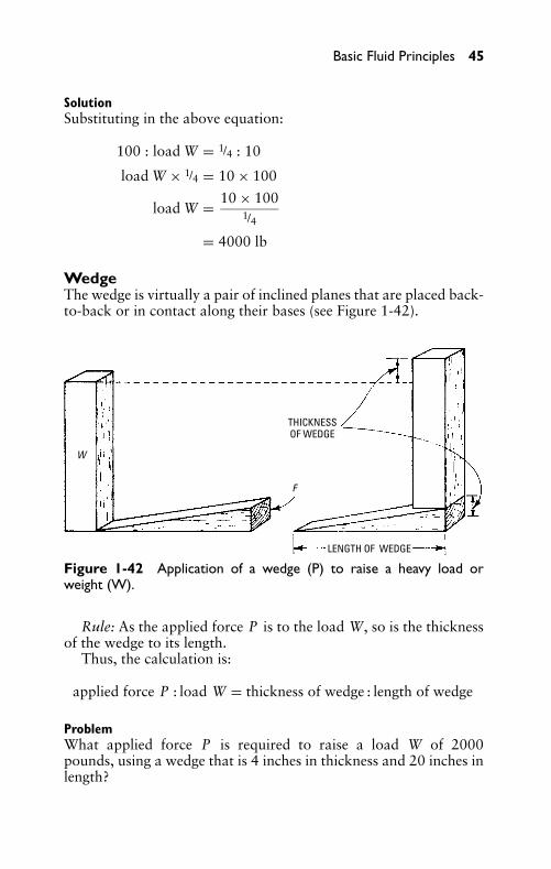
WedgeThe wedge is virtually a pair of inclined planes that are placed back-to-back or in contact along their bases (see Figure 1-42).
THICKNESSOF WEDGE
LENGTH OF WEDGE
W
F
Figure 1-42 Application of a wedge (P) to raise a heavy load orweight (W).
Rule: As the applied force P is to the load W, so is the thicknessof the wedge to its length.
Thus, the calculation is:
applied force P : load W = thickness of wedge : length of wedge
ProblemWhat applied force P is required to raise a load W of 2000pounds, using a wedge that is 4 inches in thickness and 20 inches inlength?
P1: FCH
GB098-01 GB098-Miller September 13, 2004 17:28 Char Count= 0
46 Chapter 1
SolutionSubstituting in the equation:
P (applied force) : 2000 = 4 : 20
P × 20 = 4 × 2000
P = 4 × 200020
= 400 lb
WaterIn the study of hydraulics and pumps, it is important that water andits characteristics be understood. Water is a most remarkable sub-stance. By definition, water is a compound of hydrogen and oxygenin the proportion of 2 parts by weight of hydrogen to 16 parts byweight of oxygen.
The behavior of water under the influence of temperature is ex-traordinary. When subjected to low temperatures, water is convertedto a solid (ice), which, because of its peculiar characteristic of ex-panding during its change of state, causes burst pipes and othertypes of damage. At higher temperatures, water is converted to agas (steam). Thus, water is used as a medium for developing power(as in steam for a steam engine).
At maximum density (39.1◦F) water expands as heat is added andit also expands slightly as the temperature drops from this point, asshown in Figure 1-43. Water freezes at 32◦F and boils at 212◦F,when the barometer reads 29.921 inches of mercury, which is thestandard atmosphere. The equivalent of 29.921 inches of mercuryis 14.696 psi.
Water contains approximately 5 percent air by volume (see Fig-ure 1-44), mechanically mixed with it. This is the reason that steamengines that condense moisture should have air pumps attached tothe condenser. Otherwise, the necessary vacuum cannot be main-tained.
In the operation of steam heating plants, air is liberated whenthe water boils and passes into radiators with the steam. There-fore, automatic air valves must be provided to rid the system ofthe air. If automatic air valves are not provided (or if they becomeclogged because of corrosion), radiators may become air-bound andineffective.
The boiling point of water rises as the pressure increases. Thus,the boiling point is 212◦F for standard atmospheric pressure at sealevel. The boiling point is 327.8◦F at 100 pounds (absolute) pressure.
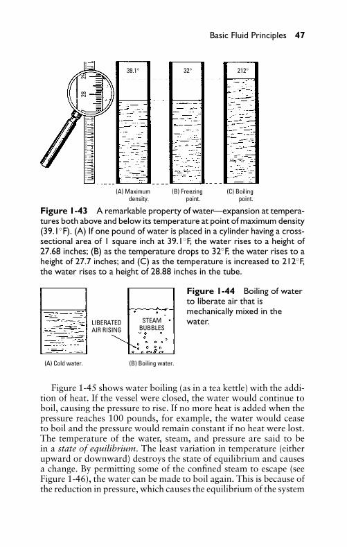
P1: FCH
GB098-01 GB098-Miller September 13, 2004 17:28 Char Count= 0
Basic Fluid Principles 47
(A) Maximum density.
(B) Freezing point.
(C) Boiling point.
39.1° 32° 212°
27
2
8
2
91
2 3
4 5
6
7
8 9
101
1 12
131
415
16 1
7 18
19
20 2
122
23 2
4 25
30 3
1 32
Figure 1-43 A remarkable property of water—expansion at tempera-tures both above and below its temperature at point of maximum density(39.1◦F). (A) If one pound of water is placed in a cylinder having a cross-sectional area of 1 square inch at 39.1◦F, the water rises to a height of27.68 inches; (B) as the temperature drops to 32◦F, the water rises to aheight of 27.7 inches; and (C) as the temperature is increased to 212◦F,the water rises to a height of 28.88 inches in the tube.
(A) Cold water. (B) Boiling water.
LIBERATEDAIR RISING
STEAMBUBBLES
Figure 1-44 Boiling of waterto liberate air that ismechanically mixed in thewater.
Figure 1-45 shows water boiling (as in a tea kettle) with the addi-tion of heat. If the vessel were closed, the water would continue toboil, causing the pressure to rise. If no more heat is added when thepressure reaches 100 pounds, for example, the water would ceaseto boil and the pressure would remain constant if no heat were lost.The temperature of the water, steam, and pressure are said to bein a state of equilibrium. The least variation in temperature (eitherupward or downward) destroys the state of equilibrium and causesa change. By permitting some of the confined steam to escape (seeFigure 1-46), the water can be made to boil again. This is because ofthe reduction in pressure, which causes the equilibrium of the system
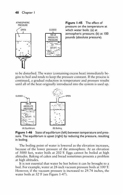
P1: FCH
GB098-01 GB098-Miller September 13, 2004 17:28 Char Count= 0
48 Chapter 1
ATMOSPHERICPRESSURE
OPEN CLOSED
100 LBABSOLUTEPRESSURE
327.8°F.
Figure 1-45 The effect ofpressure on the temperature atwhich water boils: (a) atatmospheric pressure; (b) at 100pounds (absolute pressure).
to be disturbed. The water (containing excess heat) immediately be-gins to boil and tends to keep the pressure constant. If the process iscontinued, a gradual reduction in temperature and pressure resultsuntil all of the heat originally introduced into the system is used up.
CLOSED OPEN
100 LBABSOLUTEPRESSURE
327.8°F.
(A) Equilibrium. (B) Boiling.
Figure 1-46 State of equilibrium (left) between temperature and pres-sure. The equilibrium is upset (right) by reducing the pressure, resultingin boiling.
The boiling point of water is lowered as the elevation increases,because of the lower pressure of the atmosphere. At an elevationof 5000 feet, water boils at 202◦F. Eggs cannot be boiled at highaltitudes. Baking of cakes and bread sometimes presents a problemat high altitudes.
It is not essential that water be hot before it can be brought to aboil. For example, water at 28-inch vacuum pressure boils at 100◦F.However, if the vacuum pressure is increased to 29.74 inches, thewater boils at 32◦F (see Figure 1-47).
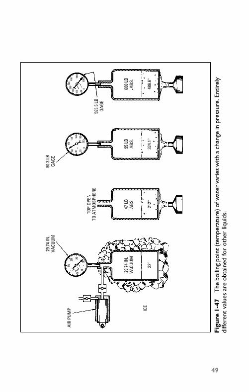
P1: FCH
GB098-01 GB098-Miller September 13, 2004 17:28 Char Count= 0
AIR
PUM
P
29.7
4 IN
.VA
CUUM
80.3
LB
GAGE
585.
5 LB
GAGE
TOP
OPEN
TO A
TMOS
PHER
E
ICE
29.7
4 IN
.VA
CUUM
95 L
BAB
S.47
LB
ABS.
600
LBAB
S.
32°
212°
324.
1°48
6.6°
0510
1520 25
300
20406010
014
0 160
180
200
05010015
0200
300
400 50
0
600
Fig
ure
1-47
The
boili
ngpo
int(
tem
pera
ture
)ofw
ater
vari
esw
itha
chan
gein
pres
sure
.Ent
irel
ydi
ffere
ntva
lues
are
obta
ined
for
othe
rliq
uids
.
49
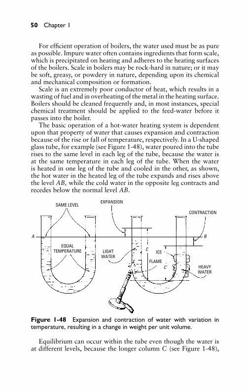
P1: FCH
GB098-01 GB098-Miller September 13, 2004 17:28 Char Count= 0
50 Chapter 1
For efficient operation of boilers, the water used must be as pureas possible. Impure water often contains ingredients that form scale,which is precipitated on heating and adheres to the heating surfacesof the boilers. Scale in boilers may be rock-hard in nature; or it maybe soft, greasy, or powdery in nature, depending upon its chemicaland mechanical composition or formation.
Scale is an extremely poor conductor of heat, which results in awasting of fuel and in overheating of the metal in the heating surface.Boilers should be cleaned frequently and, in most instances, specialchemical treatment should be applied to the feed-water before itpasses into the boiler.
The basic operation of a hot-water heating system is dependentupon that property of water that causes expansion and contractionbecause of the rise or fall of temperature, respectively. In a U-shapedglass tube, for example (see Figure 1-48), water poured into the tuberises to the same level in each leg of the tube, because the water isat the same temperature in each leg of the tube. When the wateris heated in one leg of the tube and cooled in the other, as shown,the hot water in the heated leg of the tube expands and rises abovethe level AB, while the cold water in the opposite leg contracts andrecedes below the normal level AB.
SAME LEVELEXPANSION
CONTRACTION
EQUALTEMPERATURE LIGHT
WATER
HEAVYWATER
ICE
FLAME
A B
C
C'
Figure 1-48 Expansion and contraction of water with variation intemperature, resulting in a change in weight per unit volume.
Equilibrium can occur within the tube even though the water isat different levels, because the longer column C (see Figure 1-48),
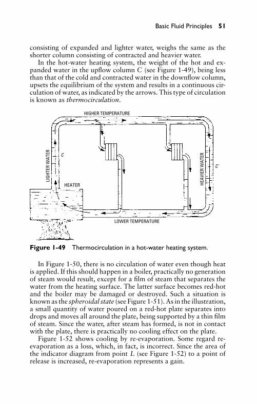
P1: FCH
GB098-01 GB098-Miller September 13, 2004 17:28 Char Count= 0
Basic Fluid Principles 51
consisting of expanded and lighter water, weighs the same as theshorter column consisting of contracted and heavier water.
In the hot-water heating system, the weight of the hot and ex-panded water in the upflow column C (see Figure 1-49), being lessthan that of the cold and contracted water in the downflow column,upsets the equilibrium of the system and results in a continuous cir-culation of water, as indicated by the arrows. This type of circulationis known as thermocirculation.
HIGHER TEMPERATURE
C
C'
LIGH
TER
WAT
ER
HEAV
IER
WAT
ER
HEATER
LOWER TEMPERATURE
Figure 1-49 Thermocirculation in a hot-water heating system.
In Figure 1-50, there is no circulation of water even though heatis applied. If this should happen in a boiler, practically no generationof steam would result, except for a film of steam that separates thewater from the heating surface. The latter surface becomes red-hotand the boiler may be damaged or destroyed. Such a situation isknown as the spheroidal state (see Figure 1-51). As in the illustration,a small quantity of water poured on a red-hot plate separates intodrops and moves all around the plate, being supported by a thin filmof steam. Since the water, after steam has formed, is not in contactwith the plate, there is practically no cooling effect on the plate.
Figure 1-52 shows cooling by re-evaporation. Some regard re-evaporation as a loss, which, in fact, is incorrect. Since the area ofthe indicator diagram from point L (see Figure 1-52) to a point ofrelease is increased, re-evaporation represents a gain.
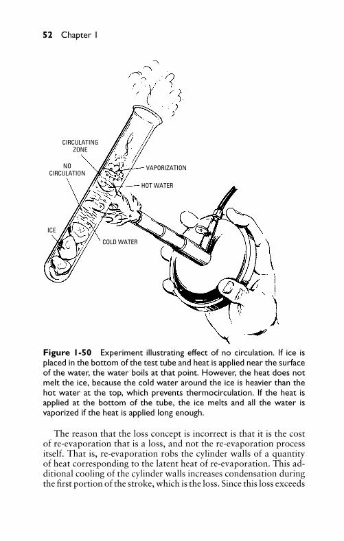
P1: FCH
GB098-01 GB098-Miller September 13, 2004 17:28 Char Count= 0
52 Chapter 1
CIRCULATINGZONE
NOCIRCULATION
VAPORIZATION
HOT WATER
ICE
COLD WATER
Figure 1-50 Experiment illustrating effect of no circulation. If ice isplaced in the bottom of the test tube and heat is applied near the surfaceof the water, the water boils at that point. However, the heat does notmelt the ice, because the cold water around the ice is heavier than thehot water at the top, which prevents thermocirculation. If the heat isapplied at the bottom of the tube, the ice melts and all the water isvaporized if the heat is applied long enough.
The reason that the loss concept is incorrect is that it is the costof re-evaporation that is a loss, and not the re-evaporation processitself. That is, re-evaporation robs the cylinder walls of a quantityof heat corresponding to the latent heat of re-evaporation. This ad-ditional cooling of the cylinder walls increases condensation duringthe first portion of the stroke, which is the loss. Since this loss exceeds
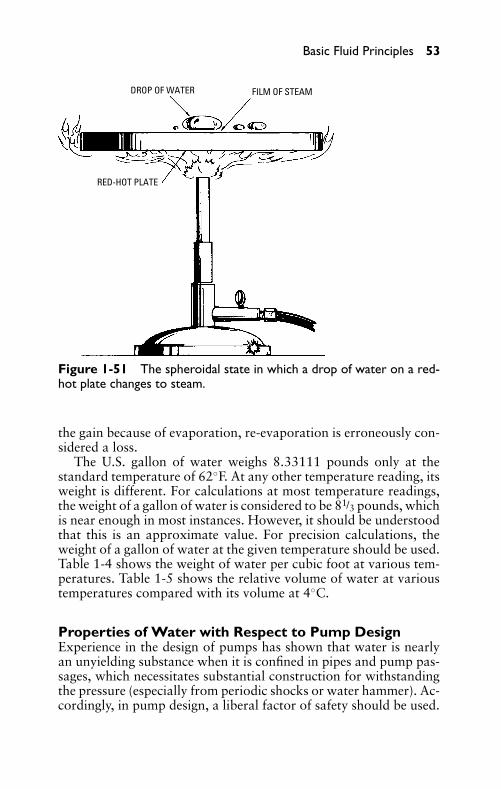
P1: FCH
GB098-01 GB098-Miller September 13, 2004 17:28 Char Count= 0
Basic Fluid Principles 53
DROP OF WATER FILM OF STEAM
RED-HOT PLATE
Figure 1-51 The spheroidal state in which a drop of water on a red-hot plate changes to steam.
the gain because of evaporation, re-evaporation is erroneously con-sidered a loss.
The U.S. gallon of water weighs 8.33111 pounds only at thestandard temperature of 62◦F. At any other temperature reading, itsweight is different. For calculations at most temperature readings,the weight of a gallon of water is considered to be 81/3 pounds, whichis near enough in most instances. However, it should be understoodthat this is an approximate value. For precision calculations, theweight of a gallon of water at the given temperature should be used.Table 1-4 shows the weight of water per cubic foot at various tem-peratures. Table 1-5 shows the relative volume of water at varioustemperatures compared with its volume at 4◦C.
Properties of Water with Respect to Pump DesignExperience in the design of pumps has shown that water is nearlyan unyielding substance when it is confined in pipes and pump pas-sages, which necessitates substantial construction for withstandingthe pressure (especially from periodic shocks or water hammer). Ac-cordingly, in pump design, a liberal factor of safety should be used.
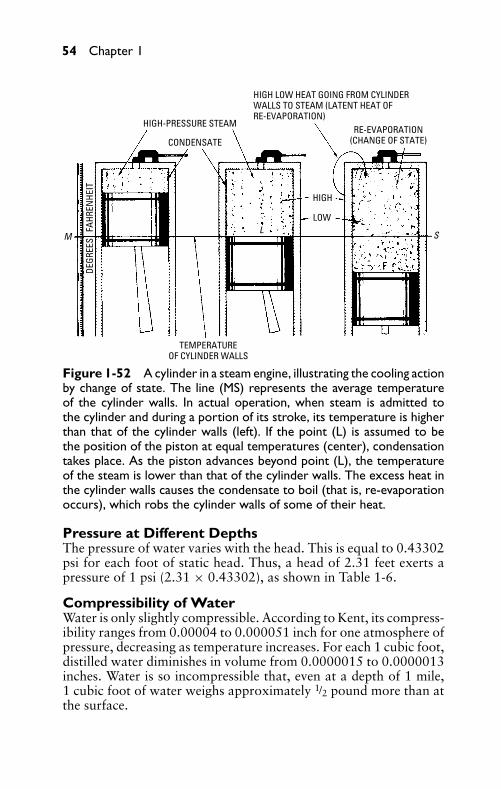
P1: FCH
GB098-01 GB098-Miller September 13, 2004 17:28 Char Count= 0
54 Chapter 1
HIGH-PRESSURE STEAM
CONDENSATERE-EVAPORATION
(CHANGE OF STATE)
TEMPERATUREOF CYLINDER WALLS
HIGH
LOW
DEGR
EES
FAH
REN
HEIT
M S
HIGH LOW HEAT GOING FROM CYLINDERWALLS TO STEAM (LATENT HEAT OFRE-EVAPORATION)
L
Figure 1-52 A cylinder in a steam engine, illustrating the cooling actionby change of state. The line (MS) represents the average temperatureof the cylinder walls. In actual operation, when steam is admitted tothe cylinder and during a portion of its stroke, its temperature is higherthan that of the cylinder walls (left). If the point (L) is assumed to bethe position of the piston at equal temperatures (center), condensationtakes place. As the piston advances beyond point (L), the temperatureof the steam is lower than that of the cylinder walls. The excess heat inthe cylinder walls causes the condensate to boil (that is, re-evaporationoccurs), which robs the cylinder walls of some of their heat.
Pressure at Different DepthsThe pressure of water varies with the head. This is equal to 0.43302psi for each foot of static head. Thus, a head of 2.31 feet exerts apressure of 1 psi (2.31 × 0.43302), as shown in Table 1-6.
Compressibility of WaterWater is only slightly compressible. According to Kent, its compress-ibility ranges from 0.00004 to 0.000051 inch for one atmosphere ofpressure, decreasing as temperature increases. For each 1 cubic foot,distilled water diminishes in volume from 0.0000015 to 0.0000013inches. Water is so incompressible that, even at a depth of 1 mile,1 cubic foot of water weighs approximately 1/2 pound more than atthe surface.
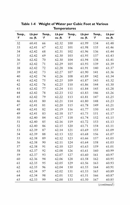
P1: FCH
GB098-01 GB098-Miller September 13, 2004 17:28 Char Count= 0
Table 1-4 Weight of Water per Cubic Foot at VariousTemperatures
Temp., Lb.per Temp., Lb.per Temp., Lb.per Temp., Lb.per◦F cu. ft. ◦F cu. ft. ◦F cu. ft. ◦F cu. ft.
32 60.41 66 62.32 100 61.99 134 61.4833 62.41 67 62.32 101 61.98 135 61.4634 62.42 68 62.31 102 61.96 136 61.4435 62.42 69 62.30 103 61.95 137 61.4336 62.42 70 62.30 104 61.94 138 61.4137 62.42 71 62.29 105 61.93 139 61.3938 62.42 72 62.28 106 61.91 140 61.3739 62.42 73 62.27 107 61.90 141 61.3640 62.42 74 62.26 108 61.89 142 61.3441 62.42 75 62.25 109 61.87 143 61.3242 62.42 76 62.25 110 61.86 144 61.3043 62.42 77 62.24 111 61.84 145 61.2844 62.42 78 62.23 112 61.83 146 61.2645 62.42 79 62.22 113 61.81 147 61.2546 62.41 80 62.21 114 61.80 148 61.2347 62.41 81 62.20 115 61.78 149 61.2148 62.41 82 62.19 116 61.77 150 61.1949 62.41 83 62.18 117 61.75 151 61.1750 62.40 84 62.17 118 61.74 152 61.1551 62.40 85 62.16 119 61.72 153 61.1352 62.40 86 62.15 120 61.71 154 61.1153 62.39 87 62.14 121 61.69 155 61.0954 62.39 88 62.13 122 61.68 156 61.0755 62.38 89 62.12 123 61.66 157 61.0556 62.38 90 62.11 124 61.64 158 61.0357 62.38 91 62.10 125 61.63 159 61.0158 62.37 92 62.08 126 61.61 160 60.9959 62.37 93 62.07 127 61.60 161 60.9760 62.36 94 62.06 128 61.58 162 60.9561 62.35 95 62.05 129 61.56 163 60.9362 62.35 96 62.04 130 61.55 164 60.9163 62.34 97 62.02 131 61.53 165 60.8964 62.34 98 62.01 132 61.51 166 60.8765 62.33 99 62.00 133 61.50 167 60.85
(continued )
55
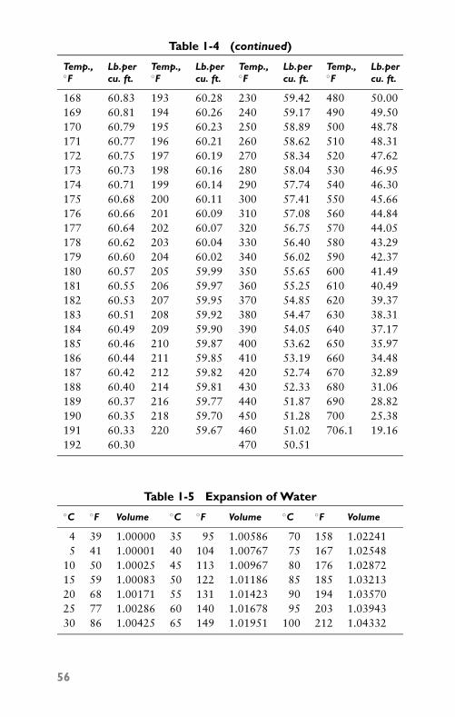
P1: FCH
GB098-01 GB098-Miller September 13, 2004 17:28 Char Count= 0
Table 1-4 (continued)
Temp., Lb.per Temp., Lb.per Temp., Lb.per Temp., Lb.per◦F cu. ft. ◦F cu. ft. ◦F cu. ft. ◦F cu. ft.
168 60.83 193 60.28 230 59.42 480 50.00169 60.81 194 60.26 240 59.17 490 49.50170 60.79 195 60.23 250 58.89 500 48.78171 60.77 196 60.21 260 58.62 510 48.31172 60.75 197 60.19 270 58.34 520 47.62173 60.73 198 60.16 280 58.04 530 46.95174 60.71 199 60.14 290 57.74 540 46.30175 60.68 200 60.11 300 57.41 550 45.66176 60.66 201 60.09 310 57.08 560 44.84177 60.64 202 60.07 320 56.75 570 44.05178 60.62 203 60.04 330 56.40 580 43.29179 60.60 204 60.02 340 56.02 590 42.37180 60.57 205 59.99 350 55.65 600 41.49181 60.55 206 59.97 360 55.25 610 40.49182 60.53 207 59.95 370 54.85 620 39.37183 60.51 208 59.92 380 54.47 630 38.31184 60.49 209 59.90 390 54.05 640 37.17185 60.46 210 59.87 400 53.62 650 35.97186 60.44 211 59.85 410 53.19 660 34.48187 60.42 212 59.82 420 52.74 670 32.89188 60.40 214 59.81 430 52.33 680 31.06189 60.37 216 59.77 440 51.87 690 28.82190 60.35 218 59.70 450 51.28 700 25.38191 60.33 220 59.67 460 51.02 706.1 19.16192 60.30 470 50.51
Table 1-5 Expansion of Water◦C ◦F Volume ◦C ◦F Volume ◦C ◦F Volume
4 39 1.00000 35 95 1.00586 70 158 1.022415 41 1.00001 40 104 1.00767 75 167 1.02548
10 50 1.00025 45 113 1.00967 80 176 1.0287215 59 1.00083 50 122 1.01186 85 185 1.0321320 68 1.00171 55 131 1.01423 90 194 1.0357025 77 1.00286 60 140 1.01678 95 203 1.0394330 86 1.00425 65 149 1.01951 100 212 1.04332
56
P1: FCH
GB098-01 GB098-Miller September 13, 2004 17:28 Char Count= 0
Basic Fluid Principles 57
AirAir is a gas that is a mixture of 23.2 percent (by weight) oxygen, 75.5percent nitrogen, and 1.3 percent argon. Other substances presentin the air or atmosphere in small amounts are 0.03 to 0.04 percentcarbonic acid, or carbon dioxide, 0.01 percent krypton, and smallamounts of several other gases. The air or atmosphere is a mixtureof the following gases by volume: 21.0 percent oxygen, 78.0 percentnitrogen, and, 0.94 percent argon.
The term free air refers to the air at atmospheric pressure. It doesnot refer to air under identical conditions. Barometer and temper-ature readings vary with the altitude of a locality and at differenttimes. Thus, free air is not necessarily the air at sea level conditions—or an absolute pressure of 14.7 psi at a temperature of 60◦F. It iscorrect to refer to the air at atmospheric condition at the point wherea compressor is installed as free air.
The average condition of the atmosphere in a temperate climateis referred to as normal air. This term is used to indicate air with36 percent relative humidity at 68◦F.
HumidityWater vapor is always present in the atmosphere. The actual quan-tity of water present in the air is referred to as absolute humidity,and it is usually expressed as grains of moisture per cubic foot ofair. A grain is 1/7000 (0.00014285) part of 1 pound. The temperatureof the air determines the amount of water that the air is capableof holding—the warmer the air, the more moisture it can hold. Forexample, the air at 80◦F can hold nearly twice the moisture as it canhold at 60◦F.
The actual amount of moisture in the air as compared with themaximum amount of moisture that the air is capable of holding ata given temperature, expressed as a percentage, is called the relativehumidity. Two thermometers (a wet-bulb and a dry-bulb thermome-ter) are required to determine relative humidity. This is a form ofhydrometer and it consists of two thermometers mounted side byside; the bulb of one thermometer is kept moist by means of a loosecotton wick tied around its bulb, the lower end of the wick dip-ping into a vessel that contains water. The wet bulb is cooled byevaporation of water from the bulb. Therefore, the wet-bulb ther-mometer indicates a lower temperature reading than the dry-bulbthermometer (the difference depending on the rate of evaporation,which, in turn, is determined by the amount of water vapor in theatmosphere). If the air is saturated with moisture, its relative humid-ity is 100 percent. Air at the same temperature, but holding one-halfthe saturation amount, has a relative humidity of 50 percent. A table
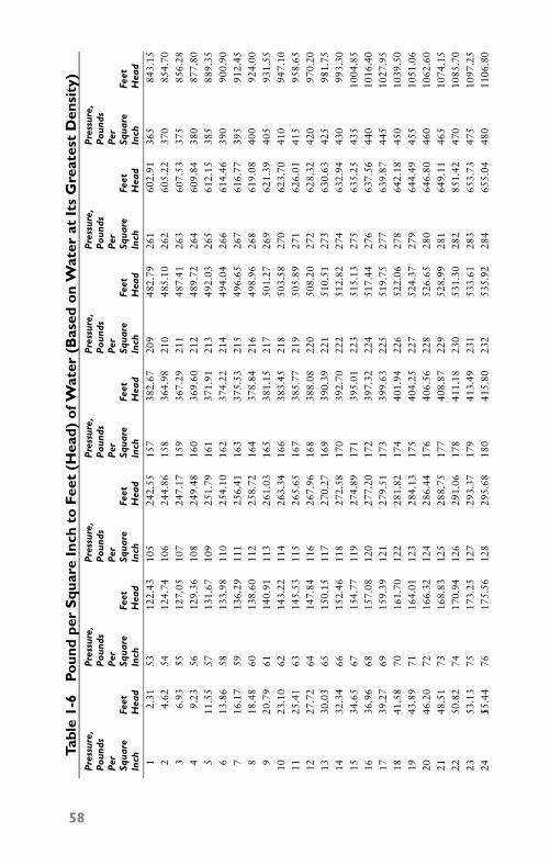
P1: FCH
GB098-01 GB098-Miller September 13, 2004 17:28 Char Count= 0
Tabl
e1-
6Po
und
per
Squ
are
Inch
toFe
et(H
ead)
ofW
ater
(Bas
edo
nW
ater
atIt
sG
reat
est
Den
sity
)P
ress
ure,
Pre
ssur
e,P
ress
ure,
Pre
ssur
e,P
ress
ure,
Pre
ssur
e,P
ress
ure,
Pou
nds
Pou
nds
Pou
nds
Pou
nds
Pou
nds
Pou
nds
Pou
nds
Per
Per
Per
Per
Per
Per
Per
Squa
reFe
etSq
uare
Feet
Squa
reFe
etSq
uare
Feet
Squa
reFe
etSq
uare
Feet
Squa
reFe
etIn
chH
ead
Inch
Hea
dIn
chH
ead
Inch
Hea
dIn
chH
ead
Inch
Hea
dIn
chH
ead
12.
3153
122.
4310
524
2.55
157
382.
6720
948
2.79
261
602.
9136
584
3.15
24.
6254
124.
7410
624
4.86
158
364.
9821
048
5.10
262
605.
2237
085
4.70
36.
9355
127.
0510
724
7.17
159
367.
2921
148
7.41
263
607.
5337
585
6.28
49.
2356
129.
3610
824
9.48
160
369.
6021
248
9.72
264
609.
8438
087
7.80
511
.55
5713
1.67
109
251.
7916
137
1.91
213
492.
0326
561
2.15
385
889.
356
13.8
658
133.
9811
025
4.10
162
374.
2221
449
4.04
266
614.
4639
090
0.90
716
.17
5913
6.29
111
256.
4116
337
5.53
215
496.
6526
761
6.77
395
912.
458
18.4
860
138.
6011
225
8.72
164
378.
8421
649
8.96
268
619.
0840
092
4.00
920
.79
6114
0.91
113
261.
0316
538
1.15
217
501.
2726
962
1.39
405
931.
5510
23.1
062
143.
2211
426
3.34
166
383.
4521
850
3.58
270
623.
7041
094
7.10
1125
.41
6314
5.53
115
265.
6516
738
5.77
219
505.
8927
162
6.01
415
958.
6512
27.7
264
147.
8411
626
7.96
168
388.
0822
050
8.20
272
628.
3242
097
0.20
1330
.03
6515
0.15
117
270.
2716
939
0.39
221
510.
5127
363
0.63
425
981.
7514
32.3
466
152.
4611
827
2.58
170
392.
7022
251
2.82
274
632.
9443
099
3.30
1534
.65
6715
4.77
119
274.
8917
139
5.01
223
515.
1327
563
5.25
435
1004
.85
1636
.96
6815
7.08
120
277.
2017
239
7.32
224
517.
4427
663
7.56
440
1016
.40
1739
.27
6915
9.39
121
279.
5117
339
9.63
225
519.
7527
763
9.87
445
1027
.95
1841
.58
7016
1.70
122
281.
8217
440
1.94
226
522.
0627
864
2.18
450
1039
.50
1943
.89
7116
4.01
123
284.
1317
540
4.25
227
524.
3727
964
4.49
455
1051
.06
2046
.20
7216
6.32
124
286.
4417
640
6.56
228
526.
6528
064
6.80
460
1062
.60
2148
.51
7316
8.83
125
288.
7517
740
8.87
229
528.
9928
164
9.11
465
1074
.15
2250
.82
7417
0.94
126
291.
0617
841
1.18
230
531.
3028
285
1.42
470
1085
.70
2353
.13
7517
3.25
127
293.
3717
941
3.49
231
533.
6128
365
3.73
475
1097
.25
2455
.44
7617
5.56
128
295.
6818
041
5.80
232
535.
9228
465
5.04
480
1106
.80
1
58
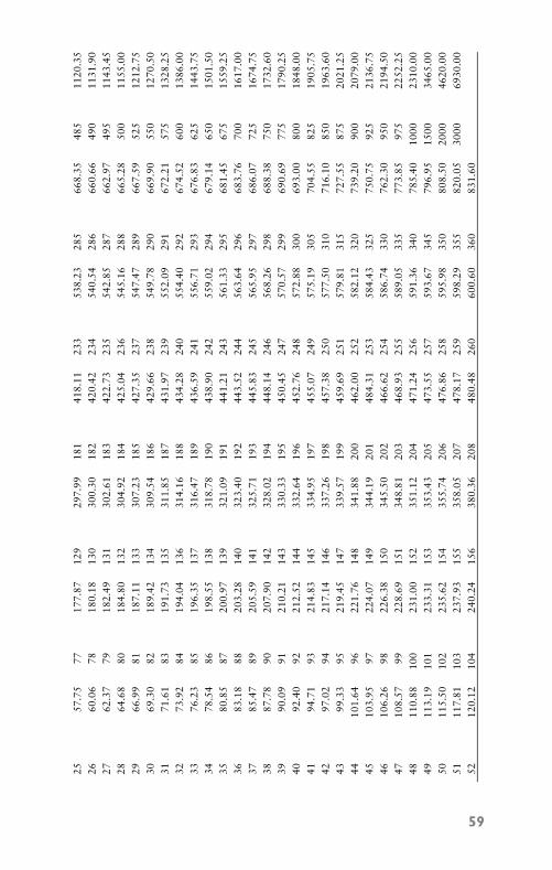
P1: FCH
GB098-01 GB098-Miller September 13, 2004 17:28 Char Count= 0
2557
.75
7717
7.87
129
297.
9918
141
8.11
233
538.
2328
566
8.35
485
1120
.35
2660
.06
7818
0.18
130
300.
3018
242
0.42
234
540.
5428
666
0.66
490
1131
.90
2762
.37
7918
2.49
131
302.
6118
342
2.73
235
542.
8528
766
2.97
495
1143
.45
2864
.68
8018
4.80
132
304.
9218
442
5.04
236
545.
1628
866
5.28
500
1155
.00
2966
.99
8118
7.11
133
307.
2318
542
7.35
237
547.
4728
966
7.59
525
1212
.75
3069
.30
8218
9.42
134
309.
5418
642
9.66
238
549.
7829
066
9.90
550
1270
.50
3171
.61
8319
1.73
135
311.
8518
743
1.97
239
552.
0929
167
2.21
575
1328
.25
3273
.92
8419
4.04
136
314.
1618
843
4.28
240
554.
4029
267
4.52
600
1386
.00
3376
.23
8519
6.35
137
316.
4718
943
6.59
241
556.
7129
367
6.83
625
1443
.75
3478
.54
8619
8.55
138
318.
7819
043
8.90
242
559.
0229
467
9.14
650
1501
.50
3580
.85
8720
0.97
139
321.
0919
144
1.21
243
561.
3329
568
1.45
675
1559
.25
3683
.18
8820
3.28
140
323.
4019
244
3.52
244
563.
6429
668
3.76
700
1617
.00
3785
.47
8920
5.59
141
325.
7119
344
5.83
245
565.
9529
768
6.07
725
1674
.75
3887
.78
9020
7.90
142
328.
0219
444
8.14
246
568.
2629
868
8.38
750
1732
.60
3990
.09
9121
0.21
143
330.
3319
545
0.45
247
570.
5729
969
0.69
775
1790
.25
4092
.40
9221
2.52
144
332.
6419
645
2.76
248
572.
8830
069
3.00
800
1848
.00
4194
.71
9321
4.83
145
334.
9519
745
5.07
249
575.
1930
570
4.55
825
1905
.75
4297
.02
9421
7.14
146
337.
2619
845
7.38
250
577.
5031
071
6.10
850
1963
.60
4399
.33
9521
9.45
147
339.
5719
945
9.69
251
579.
8131
572
7.55
875
2021
.25
4410
1.64
9622
1.76
148
341.
8820
046
2.00
252
582.
1232
073
9.20
900
2079
.00
4510
3.95
9722
4.07
149
344.
1920
148
4.31
253
584.
4332
575
0.75
925
2136
.75
4610
6.26
9822
6.38
150
345.
5020
246
6.62
254
586.
7433
076
2.30
950
2194
.50
4710
8.57
9922
8.69
151
348.
8120
346
8.93
255
589.
0533
577
3.85
975
2252
.25
4811
0.88
100
231.
0015
235
1.12
204
471.
2425
659
1.36
340
785.
4010
0023
10.0
049
113.
1910
123
3.31
153
353.
4320
547
3.55
257
593.
6734
579
6.95
1500
3465
.00
5011
5.50
102
235.
6215
435
5.74
206
476.
8625
859
5.98
350
808.
5020
0046
20.0
051
117.
8110
323
7.93
155
358.
0520
747
8.17
259
598.
2935
582
0.05
3000
6930
.00
5212
0.12
104
240.
2415
638
0.36
208
480.
4826
060
0.60
360
831.
60
59
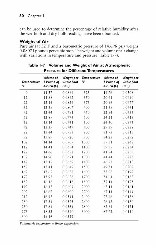
P1: FCH
GB098-01 GB098-Miller September 13, 2004 17:28 Char Count= 0
60 Chapter 1
can be used to determine the percentage of relative humidity afterthe wet-bulb and dry-bulb readings have been obtained.
Weight of AirPure air (at 32◦F and a barometric pressure of 14.696 psi) weighs0.08071 pounds per cubic foot. The weight and volume of air changewith variations in temperature and pressure (Table 1-7).
Table 1-7 Volume and Weight of Air at AtmosphericPressure for Different Temperatures
Volume of Weight per Temperature Volume of Weight perTemperature 1 Pound of Cubic Foot ◦F 1 Pound of Cubic Foot◦F Air (cu.ft.) (lbs.) Air (cu.ft.) (lbs.)
0 11.57 0.0864 325 19.76 0.050812 11.88 0.0842 350 20.41 0.049022 12.14 0.0824 375 20.96 0.047732 12.39 0.0807 400 21.69 0.046142 12.64 0.0791 450 22.94 0.043652 12.89 0.0776 500 24.21 0.041362 13.14 0.0761 600 26.60 0.037672 13.39 0.0747 700 29.59 0.033882 13.64 0.0733 800 31.75 0.031592 13.89 0.0720 900 34.25 0.0292
102 14.14 0.0707 1000 37.31 0.0268112 14.41 0.0694 1100 39.37 2.0254122 14.66 0.0682 1200 41.84 0.0239132 14.90 0.0671 1300 44.44 0.0225142 15.17 0.0659 1400 46.95 0.0213152 15.41 0.0649 1500 49.51 0.0202162 15.67 0.0638 1600 52.08 0.0192172 15.92 0.0628 1700 54.64 0.0183182 16.18 0.0618 1800 57.14 0.0175192 16.42 0.0609 2000 62.11 0.0161202 16.67 0.0600 2200 67.11 0.0149212 16.92 0.0591 2400 72.46 0.0138230 17.39 0.0575 2600 76.92 0.0130250 17.89 0.0559 2800 82.64 0.0121275 18.52 0.0540 3000 87.72 0.0114300 19.16 0.0522
Volumetric expansion = linear expansion.
P1: FCH
GB098-01 GB098-Miller September 13, 2004 17:28 Char Count= 0
Basic Fluid Principles 61
Moisture in the air has an adverse effect on an air compressor.The efficiency of the air compressor is reduced because the presenceof water vapor in the air being compressed increases the total heat-ing capacity of the air. This is due to the latent heat of the watervapor. The increased temperature increases the pressure and powerrequired for compression.
SummaryThe three states in which matter may exist are known as solid, liquid,and gas. Water is a familiar example of a substance that exists in eachof the three states of matter as ice, water, and steam, respectively.
Energy is the capacity for doing work and for overcoming resis-tance. The two types of energy are potential and kinetic.
The two types of heat are sensible and latent. The effect of heatis produced by the accelerated vibration of molecules. Heat is trans-ferred from one body to another by radiation, conduction, and con-vection.
Pressure (P) is a force exerted against an opposing body, or athrust distributed over a surface. Pressure is considered to be dis-tributed over a unit area of the surface.
Atmospheric pressure is caused by the weight of the Earth’s atmo-sphere. At sea level it is equal to about 14.69 psi. The pressure of theatmosphere does not remain constant at a given location, becauseweather conditions vary continually.
Pressure measured above that of atmospheric pressure is termedgage pressure. Pressure measured above that of a perfect vacuum istermed absolute pressure.
The barometer is used to measure atmospheric pressure. Thebarometer reading is expressed in inches of mercury. At standardatmospheric pressure, the barometer reads approximately 30 inchesof mercury. The barometer reading in inches of mercury can be con-verted to psi by multiplying the barometer reading by 0.49116.
The force that tends to draw all bodies in the Earth’s sphere to-ward the center of the Earth is known as gravity. The rate of accel-eration of gravity is approximately 32 feet per second per second.Centrifugal force tends to move a rotating body away from its centerof rotation. Centripetal force tends to move a rotating body towardits center of rotation.
A force is defined completely only when its direction, magnitude,and point of application are defined. All these factors can be repre-sented by a line or vector with an arrowhead.
Motion is described as a change in position in relation to anassumed fixed point. Motion is strictly a relative matter. Velocity isthe rate of change of position in relation to time, and acceleration
P1: FCH
GB098-01 GB098-Miller September 13, 2004 17:28 Char Count= 0
62 Chapter 1
is the rate of increase or average increase in velocity in a given unitof time.
The resistance to motion of two moving objects that touch iscalled friction. The ratio of the force required to slide a body alonga horizontal plane surface to the weight of the body is called thecoefficient of friction.
The expenditure of energy to overcome resistance through a dis-tance is work. The standard unit for measuring work is the foot-pound (ft-lb). The foot-pound is the amount of work that is donein raising 1 pound a distance of 1 foot, or in overcoming a pressureof 1 pound through a distance of 1 foot.
Power is the rate at which work is done, or work divided by thetime in which it is done. The standard unit for measuring poweris the horsepower (hp), which is defined as 33,000 foot-pounds perminute. The formula that can be used to calculate engine horsepoweris as follows:
hp = 2 PLAN33,000
The basic machines are lever, wheel and axle, pulley, inclinedplane, screw, and wedge. The Principle of Moments is important instudying the basic machines.
An important property of water is that it varies in weight (poundper unit volume) with changes in temperature, giving rise to circula-tion in boilers and heating systems. A U.S. gallon of water (231 cubicinches) weights 8.33111 pounds at 62◦F.
Air is a gas that is a mixture of 23.2 percent (by weight) oxy-gen, 75.5 percent nitrogen, and 1.3 percent argon. Other substancespresent are 0.03 to 0.04 percent carbonic acid, or carbon dioxide,0.01 percent krypton, and small quantities of several other gases.Air is a mixture (by volume) of 21.0 percent oxygen, 78.0 percentnitrogen, and 0.94 percent argon.
Humidity is the water vapor that is always present in the atmo-sphere. The actual quantity of water present is absolute humidity,and it is usually expressed as grains of moisture per cubic foot of air.A grain is 1/7000 part of one pound. The actual amount of moisturein the air as compared with the maximum amount of moisture thatthe air is capable of holding, expressed as a percentage, is calledrelative humidity.
Review Questions1. What is the definition of matter?2. What are the three states of matter?
P1: FCH
GB098-01 GB098-Miller September 13, 2004 17:28 Char Count= 0
Basic Fluid Principles 63
3. What is the definition of energy?4. What are the two forms of energy?5. State the Law of Conservation of Energy.6. What are the two forms of heat?7. What is the unit of heat?8. What is meant by the specific heat of a substance?9. What are the three methods of transferring heat?
10. What is meant by pressure?11. What is the value for standard atmospheric pressure?12. What is the difference between gage pressure and absolute
pressure?13. How is atmospheric pressure measured?14. What is the definition of gravity?15. What is the difference between centrifugal force and cen-
tripetal force?16. What is the definition of motion?17. Explain the difference between momentum and inertia.18. What is friction, and what is its cause?19. Explain the difference between work and power.20. What is the standard unit of work? Of power?21. State the Principle of Moments.22. What elements are found in air?23. What is the definition of humidity?24. What is inertia?25. What did Joule’s experiment reveal?26. What is the difference between latent heat and sensible heat?27. What are some of the disadvantages of expansion and con-
traction caused by changes in temperature?28. What does a barometer measure?29. What is meant by state of equilibrium?30. What are Newton’s three laws of motion?31. What are the two states of inertia?32. What does coefficient of friction mean?33. What are the three laws of friction?34. What does the term fulcrum mean?
P1: FCH
GB098-01 GB098-Miller September 13, 2004 17:28 Char Count= 0
64 Chapter 1
35. What is the point of maximum density of water?36. What does a gallon of water weigh?37. How compressible is water?38. What is the weight of pure air at 32◦F and a barometric pres-
sure of 14.696 pounds?39. How is relative humidity found?40. What causes the efficiency of an air compressor to decrease?
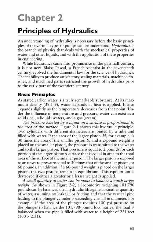
P1: JYC
GB098-02 GB098-Miller September 22, 2004 17:44 Char Count= 0
Chapter 2Principles of HydraulicsAn understanding of hydraulics is necessary before the basic princi-ples of the various types of pumps can be understood. Hydraulics isthe branch of physics that deals with the mechanical properties ofwater and other liquids, and with the application of these propertiesin engineering.
While hydraulics came into prominence in the past half century,it is not new. Blaise Pascal, a French scientist in the seventeenthcentury, evolved the fundamental law for the science of hydraulics.The inability to produce satisfactory sealing materials, machined fin-ishes, and machined parts restricted the growth of hydraulics priorto the early part of the twentieth century.
Basic PrinciplesAs stated earlier, water is a truly remarkable substance. At its max-imum density (39.1◦F), water expands as heat is applied. It alsoexpands slightly as the temperature decreases from that point. Un-der the influence of temperature and pressure, water can exist as asolid (ice), a liquid (water), and a gas (steam).
The pressure exerted by a liquid on a surface is proportional tothe area of the surface. Figure 2-1 shows this hydraulic principle.Two cylinders with different diameters are jointed by a tube andfilled with water. If the area of the larger piston M, for example, is30 times the area of the smaller piston S , and a 2-pound weight isplaced on the smaller piston, the pressure is transmitted to the waterand to the larger piston. That pressure is equal to 2 pounds for eachportion of the larger piston’s surface that is equal in area to the totalarea of the surface of the smaller piston. The larger piston is exposedto an upward pressure equal to 30 times that of the smaller piston, or60 pounds. In addition, if a 60-pound weight is placed on the largerpiston, the two pistons remain in equilibrium. This equilibrium isdestroyed if either a greater or a lesser weight is applied.
A small quantity of water can be made to balance a much largerweight. As shown in Figure 2-2, a locomotive weighing 101,790pounds can be balanced on a hydraulic lift against a smaller quantityof water, assuming no leakage or friction and that the vertical pipeleading to the plunger cylinder is exceedingly small in diameter. Forexample, if the area of the plunger requires 100 psi pressure onthe plunger to balance the 101,790-pound locomotive, the load isbalanced when the pipe is filled with water to a height of 231 feet(100 × 2.31).
65
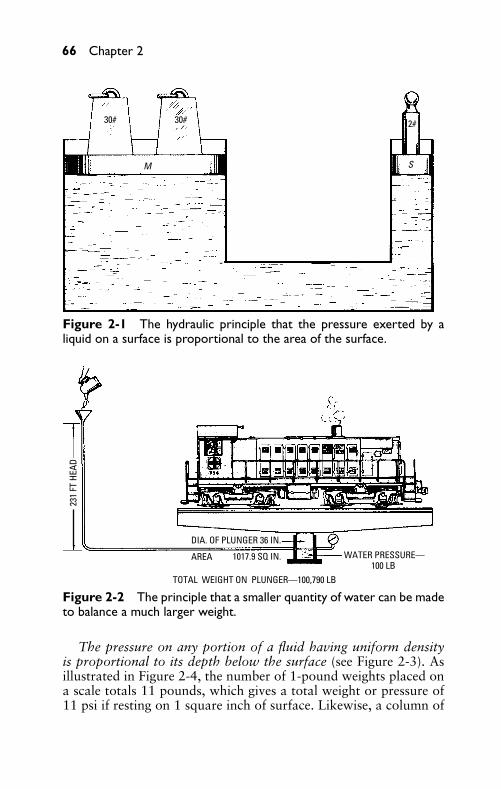
P1: JYC
GB098-02 GB098-Miller September 22, 2004 17:44 Char Count= 0
66 Chapter 2
30# 30# 2#
M S
Figure 2-1 The hydraulic principle that the pressure exerted by aliquid on a surface is proportional to the area of the surface.
TOTAL WEIGHT ON PLUNGER—100,790 LB
231
FT H
EAD
DIA. OF PLUNGER 36 IN.
AREA 1017.9 SQ IN. WATER PRESSURE —100 LB
Figure 2-2 The principle that a smaller quantity of water can be madeto balance a much larger weight.
The pressure on any portion of a fluid having uniform densityis proportional to its depth below the surface (see Figure 2-3). Asillustrated in Figure 2-4, the number of 1-pound weights placed ona scale totals 11 pounds, which gives a total weight or pressure of11 psi if resting on 1 square inch of surface. Likewise, a column of
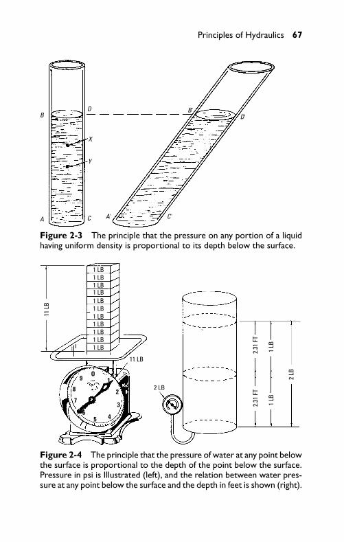
P1: JYC
GB098-02 GB098-Miller September 22, 2004 17:44 Char Count= 0
Principles of Hydraulics 67
A
BD
X
Y
C A' C'
B' D'
Figure 2-3 The principle that the pressure on any portion of a liquidhaving uniform density is proportional to its depth below the surface.
11 L
B
11 LB
2 LB
2 LB
1 LB1 LB1 LB
1 LB1 LB1 LB1 LB1 LB1 LB1 LB
2.31
FT
1 LB
1 LB
2.31
FT
1 LB
O
8
7
5 4
3
2
9 1
6
Figure 2-4 The principle that the pressure of water at any point belowthe surface is proportional to the depth of the point below the surface.Pressure in psi is Illustrated (left), and the relation between water pres-sure at any point below the surface and the depth in feet is shown (right).
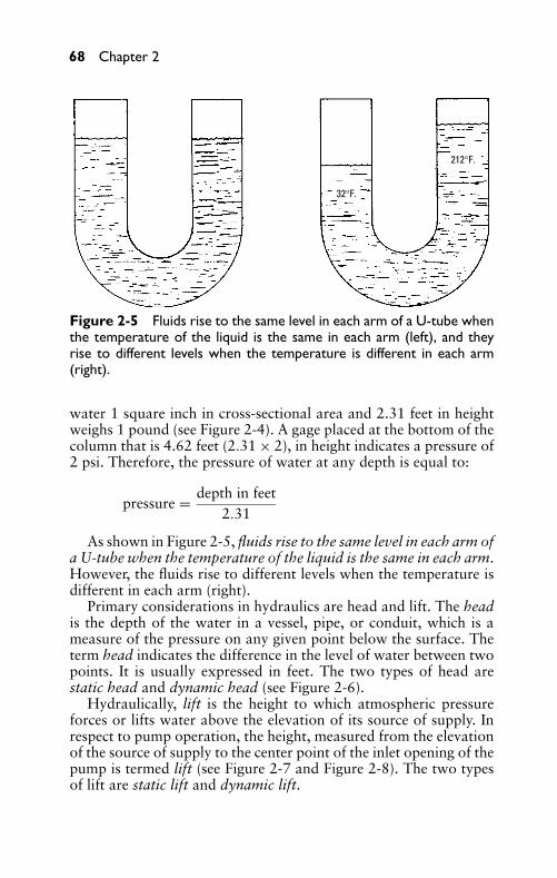
P1: JYC
GB098-02 GB098-Miller September 22, 2004 17:44 Char Count= 0
68 Chapter 2
32°F.
212°F.
Figure 2-5 Fluids rise to the same level in each arm of a U-tube whenthe temperature of the liquid is the same in each arm (left), and theyrise to different levels when the temperature is different in each arm(right).
water 1 square inch in cross-sectional area and 2.31 feet in heightweighs 1 pound (see Figure 2-4). A gage placed at the bottom of thecolumn that is 4.62 feet (2.31 × 2), in height indicates a pressure of2 psi. Therefore, the pressure of water at any depth is equal to:
pressure = depth in feet2.31
As shown in Figure 2-5, fluids rise to the same level in each arm ofa U-tube when the temperature of the liquid is the same in each arm.However, the fluids rise to different levels when the temperature isdifferent in each arm (right).
Primary considerations in hydraulics are head and lift. The headis the depth of the water in a vessel, pipe, or conduit, which is ameasure of the pressure on any given point below the surface. Theterm head indicates the difference in the level of water between twopoints. It is usually expressed in feet. The two types of head arestatic head and dynamic head (see Figure 2-6).
Hydraulically, lift is the height to which atmospheric pressureforces or lifts water above the elevation of its source of supply. Inrespect to pump operation, the height, measured from the elevationof the source of supply to the center point of the inlet opening of thepump is termed lift (see Figure 2-7 and Figure 2-8). The two typesof lift are static lift and dynamic lift.
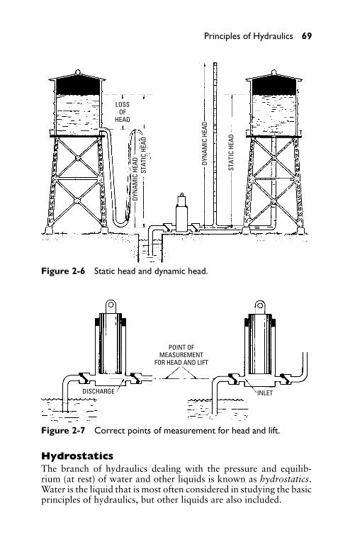
P1: JYC
GB098-02 GB098-Miller September 22, 2004 17:44 Char Count= 0
Principles of Hydraulics 69
LOSSOF
HEAD
DYN
AMIC
HEA
D DYN
AMIC
HEA
D
STAT
IC H
EAD
STAT
IC H
EAD
Figure 2-6 Static head and dynamic head.
DISCHARGE
POINT OFMEASUREMENT
FOR HEAD AND LIFT
INLET
Figure 2-7 Correct points of measurement for head and lift.
HydrostaticsThe branch of hydraulics dealing with the pressure and equilib-rium (at rest) of water and other liquids is known as hydrostatics.Water is the liquid that is most often considered in studying the basicprinciples of hydraulics, but other liquids are also included.
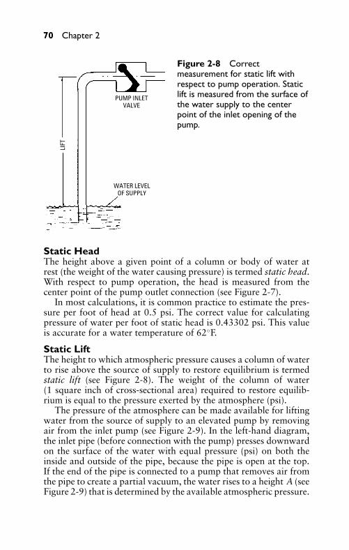
P1: JYC
GB098-02 GB098-Miller September 22, 2004 17:44 Char Count= 0
70 Chapter 2
LIFT
PUMP INLETVALVE
WATER LEVELOF SUPPLY
Figure 2-8 Correctmeasurement for static lift withrespect to pump operation. Staticlift is measured from the surface ofthe water supply to the centerpoint of the inlet opening of thepump.
Static HeadThe height above a given point of a column or body of water atrest (the weight of the water causing pressure) is termed static head.With respect to pump operation, the head is measured from thecenter point of the pump outlet connection (see Figure 2-7).
In most calculations, it is common practice to estimate the pres-sure per foot of head at 0.5 psi. The correct value for calculatingpressure of water per foot of static head is 0.43302 psi. This valueis accurate for a water temperature of 62◦F.
Static LiftThe height to which atmospheric pressure causes a column of waterto rise above the source of supply to restore equilibrium is termedstatic lift (see Figure 2-8). The weight of the column of water(1 square inch of cross-sectional area) required to restore equilib-rium is equal to the pressure exerted by the atmosphere (psi).
The pressure of the atmosphere can be made available for liftingwater from the source of supply to an elevated pump by removingair from the inlet pump (see Figure 2-9). In the left-hand diagram,the inlet pipe (before connection with the pump) presses downwardon the surface of the water with equal pressure (psi) on both theinside and outside of the pipe, because the pipe is open at the top.If the end of the pipe is connected to a pump that removes air fromthe pipe to create a partial vacuum, the water rises to a height A (seeFigure 2-9) that is determined by the available atmospheric pressure.
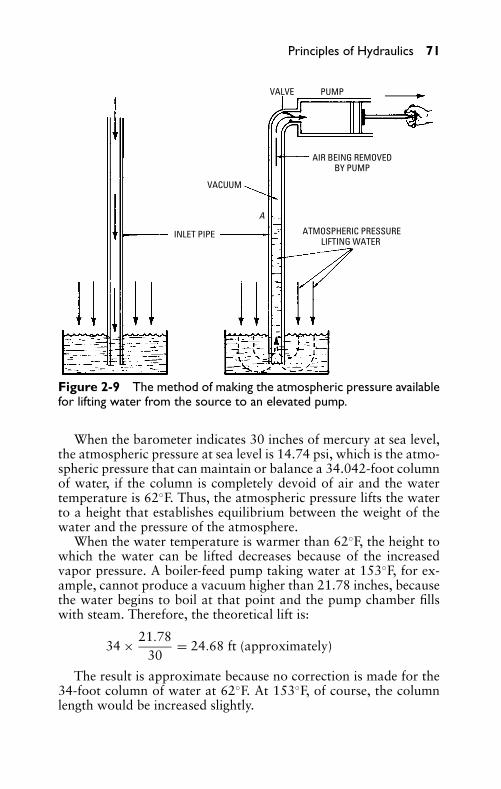
P1: JYC
GB098-02 GB098-Miller September 22, 2004 17:44 Char Count= 0
Principles of Hydraulics 71
VALVE PUMP
AIR BEING REMOVEDBY PUMP
ATMOSPHERIC PRESSURELIFTING WATER
INLET PIPE
VACUUM
A
Figure 2-9 The method of making the atmospheric pressure availablefor lifting water from the source to an elevated pump.
When the barometer indicates 30 inches of mercury at sea level,the atmospheric pressure at sea level is 14.74 psi, which is the atmo-spheric pressure that can maintain or balance a 34.042-foot columnof water, if the column is completely devoid of air and the watertemperature is 62◦F. Thus, the atmospheric pressure lifts the waterto a height that establishes equilibrium between the weight of thewater and the pressure of the atmosphere.
When the water temperature is warmer than 62◦F, the height towhich the water can be lifted decreases because of the increasedvapor pressure. A boiler-feed pump taking water at 153◦F, for ex-ample, cannot produce a vacuum higher than 21.78 inches, becausethe water begins to boil at that point and the pump chamber fillswith steam. Therefore, the theoretical lift is:
34 × 21.7830
= 24.68 ft (approximately)
The result is approximate because no correction is made for the34-foot column of water at 62◦F. At 153◦F, of course, the columnlength would be increased slightly.
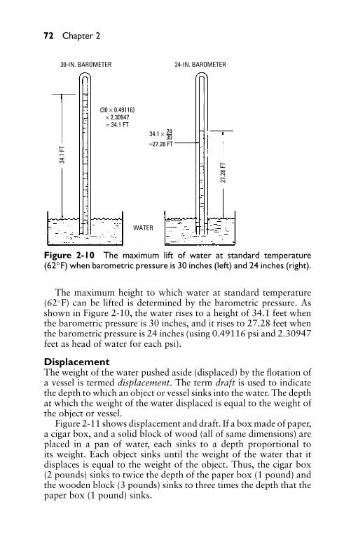
P1: JYC
GB098-02 GB098-Miller September 22, 2004 17:44 Char Count= 0
72 Chapter 2
34.1
FT
30-IN. BAROMETER 24-IN. BAROMETER
(30 × 0.49116)× 2.30947= 34.1 FT
27.2
8 FT
WATER
34.1 × =27.28 FT
24 30
Figure 2-10 The maximum lift of water at standard temperature(62◦F) when barometric pressure is 30 inches (left) and 24 inches (right).
The maximum height to which water at standard temperature(62◦F) can be lifted is determined by the barometric pressure. Asshown in Figure 2-10, the water rises to a height of 34.1 feet whenthe barometric pressure is 30 inches, and it rises to 27.28 feet whenthe barometric pressure is 24 inches (using 0.49116 psi and 2.30947feet as head of water for each psi).
DisplacementThe weight of the water pushed aside (displaced) by the flotation ofa vessel is termed displacement. The term draft is used to indicatethe depth to which an object or vessel sinks into the water. The depthat which the weight of the water displaced is equal to the weight ofthe object or vessel.
Figure 2-11 shows displacement and draft. If a box made of paper,a cigar box, and a solid block of wood (all of same dimensions) areplaced in a pan of water, each sinks to a depth proportional toits weight. Each object sinks until the weight of the water that itdisplaces is equal to the weight of the object. Thus, the cigar box(2 pounds) sinks to twice the depth of the paper box (1 pound) andthe wooden block (3 pounds) sinks to three times the depth that thepaper box (1 pound) sinks.
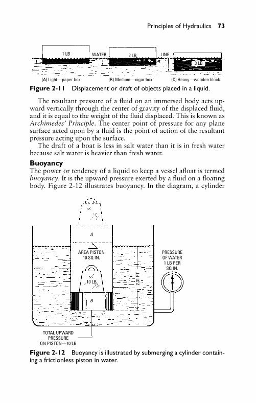
P1: JYC
GB098-02 GB098-Miller September 22, 2004 17:44 Char Count= 0
Principles of Hydraulics 73
1 LB 2 LB
3 LB
(A) Light—paper box. (B) Medium—cigar box. (C) Heavy—wooden block.
WATER LINE
Figure 2-11 Displacement or draft of objects placed in a liquid.
The resultant pressure of a fluid on an immersed body acts up-ward vertically through the center of gravity of the displaced fluid,and it is equal to the weight of the fluid displaced. This is known asArchimedes’ Principle. The center point of pressure for any planesurface acted upon by a fluid is the point of action of the resultantpressure acting upon the surface.
The draft of a boat is less in salt water than it is in fresh waterbecause salt water is heavier than fresh water.
BuoyancyThe power or tendency of a liquid to keep a vessel afloat is termedbuoyancy. It is the upward pressure exerted by a fluid on a floatingbody. Figure 2-12 illustrates buoyancy. In the diagram, a cylinder
AREA PISTON10 SQ IN.
PRESSUREOF WATER1 LB PER
SQ IN.
TOTAL UPWARDPRESSURE
ON PISTON—10 LB
A
B
10 LB 2.31
FT
Figure 2-12 Buoyancy is illustrated by submerging a cylinder contain-ing a frictionless piston in water.
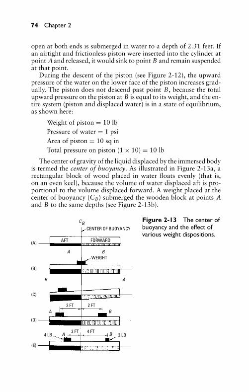
P1: JYC
GB098-02 GB098-Miller September 22, 2004 17:44 Char Count= 0
74 Chapter 2
open at both ends is submerged in water to a depth of 2.31 feet. Ifan airtight and frictionless piston were inserted into the cylinder atpoint A and released, it would sink to point B and remain suspendedat that point.
During the descent of the piston (see Figure 2-12), the upwardpressure of the water on the lower face of the piston increases grad-ually. The piston does not descend past point B, because the totalupward pressure on the piston at B is equal to its weight, and the en-tire system (piston and displaced water) is in a state of equilibrium,as shown here:
Weight of piston = 10 lbPressure of water = 1 psiArea of piston = 10 sq inTotal pressure on piston (1 × 10) = 10 lb
The center of gravity of the liquid displaced by the immersed bodyis termed the center of buoyancy. As illustrated in Figure 2-13a, arectangular block of wood placed in water floats evenly (that is,on an even keel), because the volume of water displaced aft is pro-portional to the volume displaced forward. A weight placed at thecenter of buoyancy (CB) submerged the wooden block at points Aand B to the same depths (see Figure 2-13b).
C
A
A
A
A
B
B
B
B
(A)
(B)
(C)
(D)
(E)
CENTER OF BUOYANCY
WEIGHT
2 FT
2 FT
2 FT
4 FT4 LB 2 LB
B
AFT FORWARD
Figure 2-13 The center ofbuoyancy and the effect ofvarious weight dispositions.
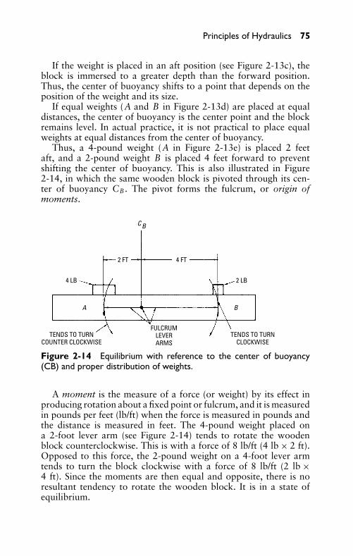
P1: JYC
GB098-02 GB098-Miller September 22, 2004 17:44 Char Count= 0
Principles of Hydraulics 75
If the weight is placed in an aft position (see Figure 2-13c), theblock is immersed to a greater depth than the forward position.Thus, the center of buoyancy shifts to a point that depends on theposition of the weight and its size.
If equal weights (A and B in Figure 2-13d) are placed at equaldistances, the center of buoyancy is the center point and the blockremains level. In actual practice, it is not practical to place equalweights at equal distances from the center of buoyancy.
Thus, a 4-pound weight (A in Figure 2-13e) is placed 2 feetaft, and a 2-pound weight B is placed 4 feet forward to preventshifting the center of buoyancy. This is also illustrated in Figure2-14, in which the same wooden block is pivoted through its cen-ter of buoyancy CB . The pivot forms the fulcrum, or origin ofmoments.
4 LB 2 LB
TENDS TO TURNCOUNTER CLOCKWISE
TENDS TO TURNCLOCKWISE
FULCRUMLEVERARMS
2 FT 4 FT
C B
A B
Figure 2-14 Equilibrium with reference to the center of buoyancy(CB) and proper distribution of weights.
A moment is the measure of a force (or weight) by its effect inproducing rotation about a fixed point or fulcrum, and it is measuredin pounds per feet (lb/ft) when the force is measured in pounds andthe distance is measured in feet. The 4-pound weight placed ona 2-foot lever arm (see Figure 2-14) tends to rotate the woodenblock counterclockwise. This is with a force of 8 lb/ft (4 lb × 2 ft).Opposed to this force, the 2-pound weight on a 4-foot lever armtends to turn the block clockwise with a force of 8 lb/ft (2 lb ×4 ft). Since the moments are then equal and opposite, there is noresultant tendency to rotate the wooden block. It is in a state ofequilibrium.
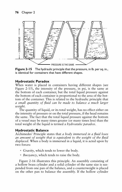
P1: JYC
GB098-02 GB098-Miller September 22, 2004 17:44 Char Count= 0
76 Chapter 2
COM
MON
-HEA
D
PRESSURE IS THE SAME
Figure 2-15 The hydraulic principle that the pressure, in lb. per sq. in.,is identical for containers that have different shapes.
Hydrostatic ParadoxWhen water is placed in containers having different shapes (seeFigure 2-15), the intensity of the pressure, in psi, is the same atthe bottom of each container, but the total liquid pressure againstthe bottom of each container is proportional to the area of the bot-tom of the container. This is related to the hydraulic principle thata small quantity of fluid can be made to balance a much largerweight.
The quantity of liquid, or its total weight, has no effect either onthe intensity of pressure or on the total pressure, if the head remainsthe same. The fact that the total liquid pressure against the bottomof a vessel may be many times greater (or many times less) than thetotal weight of the liquid is termed a hydrostatic paradox.
Hydrostatic BalanceArchimedes’ Principle states that a body immersed in a fluid losesan amount of weight that is equivalent to the weight of the fluiddisplaced. When a body is immersed in a liquid, it is acted upon bytwo forces:
� Gravity, which tends to lower the body.� Buoyancy, which tends to raise the body.
Figure 2-16 illustrates this principle. An assembly consisting ofa hollow brass cylinder and a solid cylinder of the same size is sus-pended from one pan of the balance, and a counterweight is placedon the other pan to balance the assembly. If the hollow cylinder
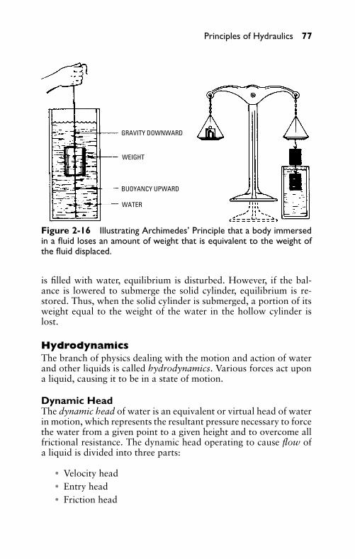
P1: JYC
GB098-02 GB098-Miller September 22, 2004 17:44 Char Count= 0
Principles of Hydraulics 77
GRAVITY DOWNWARD
WEIGHT
BUOYANCY UPWARD
WATER
Figure 2-16 Illustrating Archimedes’ Principle that a body immersedin a fluid loses an amount of weight that is equivalent to the weight ofthe fluid displaced.
is filled with water, equilibrium is disturbed. However, if the bal-ance is lowered to submerge the solid cylinder, equilibrium is re-stored. Thus, when the solid cylinder is submerged, a portion of itsweight equal to the weight of the water in the hollow cylinder islost.
HydrodynamicsThe branch of physics dealing with the motion and action of waterand other liquids is called hydrodynamics. Various forces act upona liquid, causing it to be in a state of motion.
Dynamic HeadThe dynamic head of water is an equivalent or virtual head of waterin motion, which represents the resultant pressure necessary to forcethe water from a given point to a given height and to overcome allfrictional resistance. The dynamic head operating to cause flow ofa liquid is divided into three parts:
� Velocity head� Entry head� Friction head
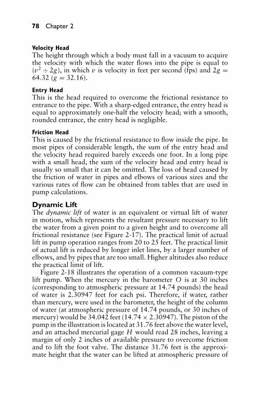
P1: JYC
GB098-02 GB098-Miller September 22, 2004 17:44 Char Count= 0
78 Chapter 2
Velocity HeadThe height through which a body must fall in a vacuum to acquirethe velocity with which the water flows into the pipe is equal to(v2 ÷ 2g), in which v is velocity in feet per second (fps) and 2g =64.32 (g = 32.16).
Entry HeadThis is the head required to overcome the frictional resistance toentrance to the pipe. With a sharp-edged entrance, the entry head isequal to approximately one-half the velocity head; with a smooth,rounded entrance, the entry head is negligible.
Friction HeadThis is caused by the frictional resistance to flow inside the pipe. Inmost pipes of considerable length, the sum of the entry head andthe velocity head required barely exceeds one foot. In a long pipewith a small head, the sum of the velocity head and entry head isusually so small that it can be omitted. The loss of head caused bythe friction of water in pipes and elbows of various sizes and thevarious rates of flow can be obtained from tables that are used inpump calculations.
Dynamic LiftThe dynamic lift of water is an equivalent or virtual lift of waterin motion, which represents the resultant pressure necessary to liftthe water from a given point to a given height and to overcome allfrictional resistance (see Figure 2-17). The practical limit of actuallift in pump operation ranges from 20 to 25 feet. The practical limitof actual lift is reduced by longer inlet lines, by a larger number ofelbows, and by pipes that are too small. Higher altitudes also reducethe practical limit of lift.
Figure 2-18 illustrates the operation of a common vacuum-typelift pump. When the mercury in the barometer O is at 30 inches(corresponding to atmospheric pressure at 14.74 pounds) the headof water is 2.30947 feet for each psi. Therefore, if water, ratherthan mercury, were used in the barometer, the height of the columnof water (at atmospheric pressure of 14.74 pounds, or 30 inches ofmercury) would be 34.042 feet (14.74 × 2.30947). The piston of thepump in the illustration is located at 31.76 feet above the water level,and an attached mercurial gage H would read 28 inches, leaving amargin of only 2 inches of available pressure to overcome frictionand to lift the foot valve. The distance 31.76 feet is the approxi-mate height that the water can be lifted at atmospheric pressure of
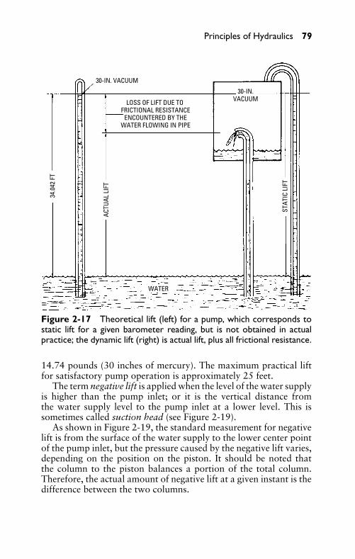
P1: JYC
GB098-02 GB098-Miller September 22, 2004 17:44 Char Count= 0
Principles of Hydraulics 79
LOSS OF LIFT DUE TO FRICTIONAL RESISTANCE
ENCOUNTERED BY THEWATER FLOWING IN PIPE
30-IN. VACUUM
34.0
42 F
T
30-IN.VACUUM
ACTU
AL L
IFT
STAT
IC L
IFT
WATER
Figure 2-17 Theoretical lift (left) for a pump, which corresponds tostatic lift for a given barometer reading, but is not obtained in actualpractice; the dynamic lift (right) is actual lift, plus all frictional resistance.
14.74 pounds (30 inches of mercury). The maximum practical liftfor satisfactory pump operation is approximately 25 feet.
The term negative lift is applied when the level of the water supplyis higher than the pump inlet; or it is the vertical distance fromthe water supply level to the pump inlet at a lower level. This issometimes called suction head (see Figure 2-19).
As shown in Figure 2-19, the standard measurement for negativelift is from the surface of the water supply to the lower center pointof the pump inlet, but the pressure caused by the negative lift varies,depending on the position on the piston. It should be noted thatthe column to the piston balances a portion of the total column.Therefore, the actual amount of negative lift at a given instant is thedifference between the two columns.
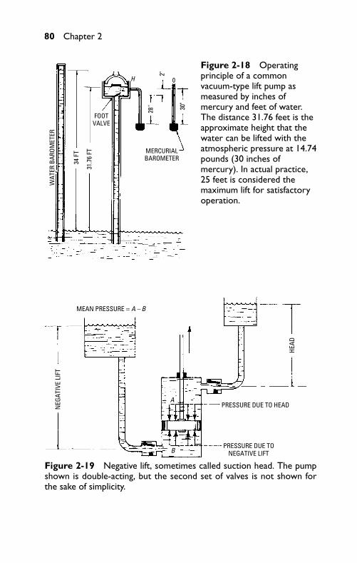
P1: JYC
GB098-02 GB098-Miller September 22, 2004 17:44 Char Count= 0
80 Chapter 2W
ATER
BAR
OMET
ER
34 F
T
28"
2"
30"
31.7
6 FT
FOOTVALVE
MERCURIALBAROMETER
0H
Figure 2-18 Operatingprinciple of a commonvacuum-type lift pump asmeasured by inches ofmercury and feet of water.The distance 31.76 feet is theapproximate height that thewater can be lifted with theatmospheric pressure at 14.74pounds (30 inches ofmercury). In actual practice,25 feet is considered themaximum lift for satisfactoryoperation.
MEAN PRESSURE = A – B
A
B
NEG
ATIV
E LI
FT
PRESSURE DUE TONEGATIVE LIFT
PRESSURE DUE TO HEAD
HEAD
Figure 2-19 Negative lift, sometimes called suction head. The pumpshown is double-acting, but the second set of valves is not shown forthe sake of simplicity.
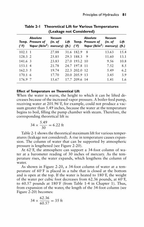
P1: JYC
GB098-02 GB098-Miller September 22, 2004 17:44 Char Count= 0
Principles of Hydraulics 81
Table 2-1 Theoretical Lift for Various Temperatures(Leakage not Considered)
Absolute Vacuum Absolute VacuumTemp. Pressure of (in. of Lift Temp. Pressure of (in. of Lift(◦F) Vapor (lb/in2) mercury) (ft.) (◦F) Vapor (lb/in2) mercury) (ft.)
102.1 1 27.88 31.6 182.9 8 13.63 15.4128.3 2 25.85 29.3 188.3 9 11.60 13.1141.6 3 23.83 27.0 193.2 10 9.56 10.8153.1 4 21.78 24.7 197.8 11 7.52 8.5162.3 5 19.74 22.3 202.0 12 5.49 6.2170.1 6 17.70 20.0 205.9 13 3.45 3.9176.9 7 15.67 17.7 209.6 14 1.41 1.6
Effect of Temperature on Theoretical LiftWhen the water is warm, the height to which it can be lifted de-creases because of the increased vapor pressure. A boiler-feed pump,receiving water at 201.96◦F, for example, could not produce a vac-uum greater than 5.49 inches, because the water at the temperaturebegins to boil, filling the pump chamber with steam. Therefore, thecorresponding theoretical lift is:
34 × 5.4930
= 6.22 ft
Table 2-1 shows the theoretical maximum lift for various temper-atures (leakage not considered). A rise in temperature causes expan-sion. The column of water that can be supported by atmosphericpressure is lengthened (see Figure 2-20).
At 62◦F, the atmosphere can support a 34-foot column of wa-ter at a barometer reading of 30 inches of mercury. As the tem-perature rises, the water expands, which lengthens the column ofwater.
As shown in Figure 2-20, a 34-foot column of water at a tem-perature of 60◦F is placed in a tube that is closed at the bottomand is open at the top. If the water is heated to 180◦F, the weightof the water per cubic foot decreases from 62.36 pounds, at 60◦F,to 60.57 pounds at 180◦F (from Table 1-4 in Chapter 1). Thus,from expansion of the water, the length of the 34-foot column (seeFigure 2-20) becomes:
34 × 62.3660.57
= 35 ft
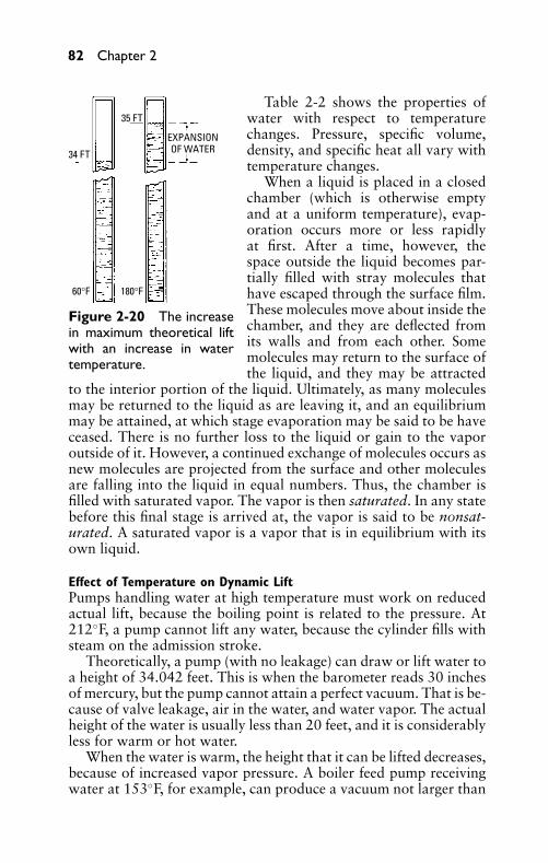
P1: JYC
GB098-02 GB098-Miller September 22, 2004 17:44 Char Count= 0
82 Chapter 2
EXPANSIONOF WATER
35 FT
34 FT
60°F 180°F
Figure 2-20 The increasein maximum theoretical liftwith an increase in watertemperature.
Table 2-2 shows the properties ofwater with respect to temperaturechanges. Pressure, specific volume,density, and specific heat all vary withtemperature changes.
When a liquid is placed in a closedchamber (which is otherwise emptyand at a uniform temperature), evap-oration occurs more or less rapidlyat first. After a time, however, thespace outside the liquid becomes par-tially filled with stray molecules thathave escaped through the surface film.These molecules move about inside thechamber, and they are deflected fromits walls and from each other. Somemolecules may return to the surface ofthe liquid, and they may be attracted
to the interior portion of the liquid. Ultimately, as many moleculesmay be returned to the liquid as are leaving it, and an equilibriummay be attained, at which stage evaporation may be said to be haveceased. There is no further loss to the liquid or gain to the vaporoutside of it. However, a continued exchange of molecules occurs asnew molecules are projected from the surface and other moleculesare falling into the liquid in equal numbers. Thus, the chamber isfilled with saturated vapor. The vapor is then saturated. In any statebefore this final stage is arrived at, the vapor is said to be nonsat-urated. A saturated vapor is a vapor that is in equilibrium with itsown liquid.
Effect of Temperature on Dynamic LiftPumps handling water at high temperature must work on reducedactual lift, because the boiling point is related to the pressure. At212◦F, a pump cannot lift any water, because the cylinder fills withsteam on the admission stroke.
Theoretically, a pump (with no leakage) can draw or lift water toa height of 34.042 feet. This is when the barometer reads 30 inchesof mercury, but the pump cannot attain a perfect vacuum. That is be-cause of valve leakage, air in the water, and water vapor. The actualheight of the water is usually less than 20 feet, and it is considerablyless for warm or hot water.
When the water is warm, the height that it can be lifted decreases,because of increased vapor pressure. A boiler feed pump receivingwater at 153◦F, for example, can produce a vacuum not larger than
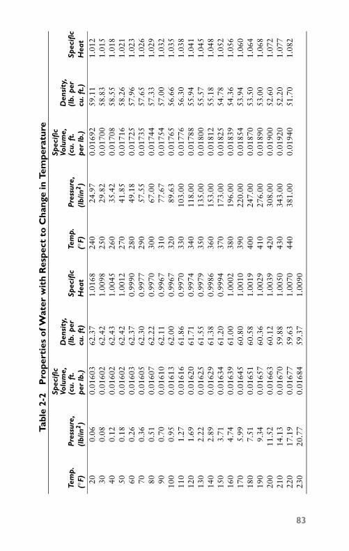
P1: JYC
GB098-02 GB098-Miller September 22, 2004 17:44 Char Count= 0
Tabl
e2-
2P
rope
rtie
so
fWat
erw
ith
Res
pect
toC
hang
ein
Tem
pera
ture
Spec
ific
Spec
ific
Volu
me,
Den
sity
,Vo
lum
e,D
ensi
ty,
Tem
p.
Pre
ssur
e,(c
u.ft
.(l
b.p
erSp
ecifi
cTe
mp
.P
ress
ure,
(cu.
ft.
(lb.
per
Spec
ific
(◦ F)
(lb/
in2)
per
lb.)
cu.f
t)H
eat
(◦ F)
(lb/
in2)
per
lb.)
cu.f
t.)
Hea
t
200.
060.
0160
362
.37
1.01
6824
024
.97
0.01
692
59.1
11.
012
300.
080.
0160
262
.42
1.00
9825
029
.82
0.01
700
58.8
31.
015
400.
120.
0160
262
.43
1.00
4526
035
.42
0.01
708
58.5
51.
018
500.
180.
0160
262
.42
1.00
1227
041
.85
0.01
716
58.2
61.
021
600.
260.
0160
362
.37
0.99
9028
049
.18
0.01
725
57.9
61.
023
700.
360.
0160
562
.30
0.99
7729
057
.55
0.01
735
57.6
51.
026
800.
510.
0160
762
.22
0.99
7030
067
.00
0.01
744
57.3
31.
029
900.
700.
0161
062
.11
0.99
6731
077
.67
0.01
754
57.0
01.
032
100
0.95
0.01
613
62.0
00.
9967
320
89.6
30.
0176
556
.66
1.03
511
01.
270.
0161
661
.86
0.99
7033
010
3.00
0.01
776
56.3
01.
038
120
1.69
0.01
620
61.7
10.
9974
340
118.
000.
0178
855
.94
1.04
113
02.
220.
0162
561
.55
0.99
7935
013
5.00
0.01
800
55.5
71.
045
140
2.89
0.01
629
61.3
80.
9986
360
153.
000.
0181
255
.18
1.04
815
03.
710.
0163
461
.20
0.99
9437
017
3.00
0.01
825
54.7
81.
052
160
4.74
0.01
639
61.0
01.
0002
380
196.
000.
0183
954
.36
1.05
617
05.
990.
0164
560
.80
1.00
1039
022
0.00
0.01
854
53.9
41.
060
180
7.51
0.01
651
60.5
81.
0019
400
247.
000.
0187
053
.50
1.06
419
09.
340.
0165
760
.36
1.00
2941
027
6.00
0.01
890
53.0
01.
068
200
11.5
20.
0166
360
.12
1.00
3942
030
8.00
0.01
900
52.6
01.
072
210
14.1
30.
0167
059
.88
1.00
5043
034
3.00
0.01
920
52.2
01.
077
220
17.1
90.
0167
759
.63
1.00
7044
038
1.00
0.01
940
51.7
01.
082
230
20.7
70.
0168
459
.37
1.00
90
83
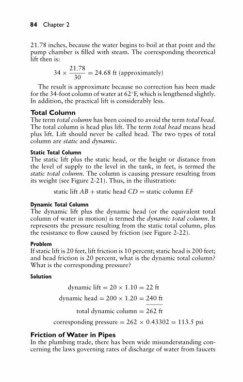
P1: JYC
GB098-02 GB098-Miller September 22, 2004 17:44 Char Count= 0
84 Chapter 2
21.78 inches, because the water begins to boil at that point and thepump chamber is filled with steam. The corresponding theoreticallift then is:
34 × 21.7830
= 24.68 ft (approximately)
The result is approximate because no correction has been madefor the 34-foot column of water at 62◦F, which is lengthened slightly.In addition, the practical lift is considerably less.
Total ColumnThe term total column has been coined to avoid the term total head.The total column is head plus lift. The term total head means headplus lift. Lift should never be called head. The two types of totalcolumn are static and dynamic.
Static Total ColumnThe static lift plus the static head, or the height or distance fromthe level of supply to the level in the tank, in feet, is termed thestatic total column. The column is causing pressure resulting fromits weight (see Figure 2-21). Thus, in the illustration:
static lift AB + static head CD = static column EF
Dynamic Total ColumnThe dynamic lift plus the dynamic head (or the equivalent totalcolumn of water in motion) is termed the dynamic total column. Itrepresents the pressure resulting from the static total column, plusthe resistance to flow caused by friction (see Figure 2-22).
ProblemIf static lift is 20 feet, lift friction is 10 percent; static head is 200 feet;and head friction is 20 percent, what is the dynamic total column?What is the corresponding pressure?
Solution
dynamic lift = 20 × 1.10 = 22 ft
dynamic head = 200 × 1.20 = 240 ft
total dynamic column = 262 ft
corresponding pressure = 262 × 0.43302 = 113.5 psi
Friction of Water in PipesIn the plumbing trade, there has been wide misunderstanding con-cerning the laws governing rates of discharge of water from faucets
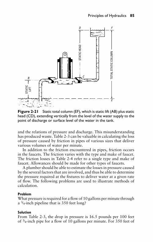
P1: JYC
GB098-02 GB098-Miller September 22, 2004 17:44 Char Count= 0
Principles of Hydraulics 85
STAT
IC H
EAD
STAT
IC
LIFT
TOTA
L ST
ATIC
COL
UMN
B
A
C
E
FD
Figure 2-21 Static total column (EF), which is static lift (AB) plus statichead (CD), extending vertically from the level of the water supply to thepoint of discharge or surface level of the water in the tank.
and the relations of pressure and discharge. This misunderstandinghas produced waste. Table 2-3 can be valuable in calculating the lossof pressure caused by friction in pipes of various sizes that delivervarious volumes of water per minute.
In addition to the friction encountered in pipes, friction occursin the faucets. The friction varies with the type and make of faucet.The friction losses in Table 2-4 refer to a single type and make offaucet. Allowances should be made for other types of faucets.
A plumber should be able to estimate the losses in pressure causedby the several factors that are involved, and thus be able to determinethe pressure required at the fixtures to deliver water at a given rateof flow. The following problems are used to illustrate methods ofcalculation.
ProblemWhat pressure is required for a flow of 10 gallons per minute througha 3/4-inch pipeline that is 350 feet long?
SolutionFrom Table 2-3, the drop in pressure is 16.5 pounds per 100 feetof 3/4-inch pipe for a flow of 10 gallons per minute. For 350 feet of
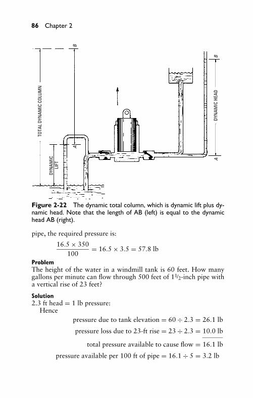
P1: JYC
GB098-02 GB098-Miller September 22, 2004 17:44 Char Count= 0
86 Chapter 2
A
A
B
B
TOTA
L DY
NAM
IC C
OLUM
N
DYN
AMIC
HEA
D
DYN
AMIC
LI
FT
Figure 2-22 The dynamic total column, which is dynamic lift plus dy-namic head. Note that the length of AB (left) is equal to the dynamichead AB (right).
pipe, the required pressure is:
16.5 × 350100
= 16.5 × 3.5 = 57.8 lb
ProblemThe height of the water in a windmill tank is 60 feet. How manygallons per minute can flow through 500 feet of 11/2-inch pipe witha vertical rise of 23 feet?
Solution2.3 ft head = 1 lb pressure:
Hencepressure due to tank elevation = 60 ÷ 2.3 = 26.1 lb
pressure loss due to 23-ft rise = 23 ÷ 2.3 = 10.0 lb
total pressure available to cause flow = 16.1 lb
pressure available per 100 ft of pipe = 16.1 ÷ 5 = 3.2 lb
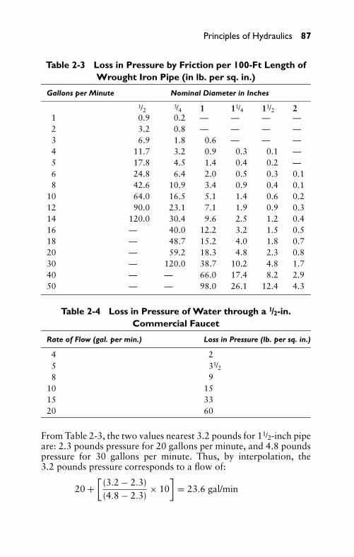
P1: JYC
GB098-02 GB098-Miller September 22, 2004 17:44 Char Count= 0
Principles of Hydraulics 87
Table 2-3 Loss in Pressure by Friction per 100-Ft Length ofWrought Iron Pipe (in lb. per sq. in.)
Gallons per Minute Nominal Diameter in Inches
1/2 3/4 1 11/4 11/2 21 0.9 0.2 — — — —2 3.2 0.8 — — — —3 6.9 1.8 0.6 — — —4 11.7 3.2 0.9 0.3 0.1 —5 17.8 4.5 1.4 0.4 0.2 —6 24.8 6.4 2.0 0.5 0.3 0.18 42.6 10.9 3.4 0.9 0.4 0.1
10 64.0 16.5 5.1 1.4 0.6 0.212 90.0 23.1 7.1 1.9 0.9 0.314 120.0 30.4 9.6 2.5 1.2 0.416 — 40.0 12.2 3.2 1.5 0.518 — 48.7 15.2 4.0 1.8 0.720 — 59.2 18.3 4.8 2.3 0.830 — 120.0 38.7 10.2 4.8 1.740 — — 66.0 17.4 8.2 2.950 — — 98.0 26.1 12.4 4.3
Table 2-4 Loss in Pressure of Water through a 1/2-in.Commercial Faucet
Rate of Flow (gal. per min.) Loss in Pressure (lb. per sq. in.)
4 25 31/28 9
10 1515 3320 60
From Table 2-3, the two values nearest 3.2 pounds for 11/2-inch pipeare: 2.3 pounds pressure for 20 gallons per minute, and 4.8 poundspressure for 30 gallons per minute. Thus, by interpolation, the3.2 pounds pressure corresponds to a flow of:
20 +[
(3.2 − 2.3)(4.8 − 2.3)
× 10]
= 23.6 gal/min
P1: JYC
GB098-02 GB098-Miller September 22, 2004 17:44 Char Count= 0
88 Chapter 2
ProblemA 3/4-inch pipe extends 75 feet with a vertical rise of 23 feet. Whatpressure is required at the water mains in the street to deliver 10 gal-lons per minute through a 1/2-inch faucet?
SolutionFrom Table 2-3:
Friction loss through 75 ft of 3/4-inch pipe = (16.5 ×75/100) = 12.4 lbLoss due to 23-ft rise (23 ÷ 2.3) = 10.0 lb
From Table 2-4:
Loss in flow through faucet at 10 gallons per minute = 15.0 lb
Therefore,
12.4 + 10 + 15.0 = 37.4 lb pressure needed
In most installations, a pressure loss caused by flow throughthe meter must be considered (Table 2-5). At a given rate of flow(30 gallons per minute), it may be noted that the loss in pressure inpassing through the meter decreases rapidly as the size of the meterincreases.
Table 2-5 Pressure-Loss in Flow through Meter
Meter Size (in) Gal. per Min. Pressure Loss (lb)
5/8 10 2–75/8 30 16–653/4 30 14–301 30 4–7
ProblemWater in a 3/4-inch pipe passes through a meter and extends 125 feetfrom a main to a faucet. The faucet is 23 feet above the street main,and must deliver 10 gallons per minute. What pressure is requiredat the main?
SolutionFrom Table 2-3:
Friction loss in 125 ft of pipe = (16.5 × 1.25) = 20.6 lbPressure loss due to 23-ft rise (23 ÷ 2.3) = 10.0 lbFrom Table 2-4: friction loss through faucet = 15.0 lbFrom Table 2-5: pressure loss through meter = 3.0 lb
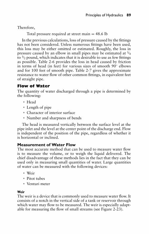
P1: JYC
GB098-02 GB098-Miller September 22, 2004 17:44 Char Count= 0
Principles of Hydraulics 89
Therefore,
Total pressure required at street main = 48.6 lb
In the previous calculations, loss of pressure caused by the fittingshas not been considered. Unless numerous fittings have been used,this loss may be either omitted or estimated. Roughly, the loss inpressure caused by an elbow in small pipes may be estimated at 1/4to 1/2 pound, which indicates that it is desirable to use as few fittingsas possible. Table 2-6 provides the loss in head caused by frictionin terms of head (in feet) for various sizes of smooth 90◦ elbowsand for 100 feet of smooth pipe. Table 2-7 gives the approximateresistance to water flow of other common fittings, in equivalent feetof straight pipe.
Flow of WaterThe quantity of water discharged through a pipe is determined bythe following:
� Head� Length of pipe� Character of interior surface� Number and sharpness of bends
The head is measured vertically between the surface level at thepipe inlet and the level at the center point of the discharge end. Flowis independent of the position of the pipe, regardless of whether itis horizontal or inclined.
Measurement of Water FlowThe most accurate method that can be used to measure water flowis to measure the volume, or to weigh the liquid delivered. Thechief disadvantage of these methods lies in the fact that they can beused only in measuring small quantities of water. Large quantitiesof water can be measured with the following devices:
� Weir� Pitot tubes� Venturi meter
WeirThe weir is a device that is commonly used to measure water flow. Itconsists of a notch in the vertical side of a tank or reservoir throughwhich water may flow to be measured. The weir is especially adapt-able for measuring the flow of small streams (see Figure 2-23).
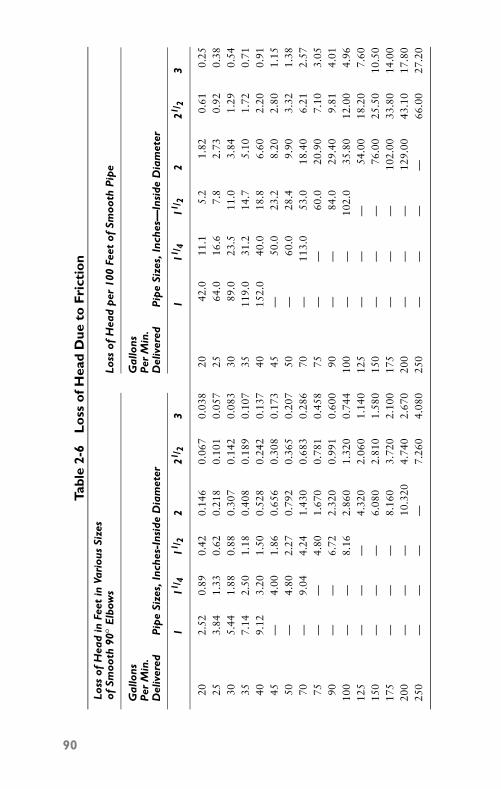
P1: JYC
GB098-02 GB098-Miller September 22, 2004 17:44 Char Count= 0
Tabl
e2-
6L
oss
ofH
ead
Due
toFr
icti
on
Loss
ofH
ead
inFe
etin
Vari
ous
Size
sof
Smoo
th90
◦E
lbow
sLo
ssof
Hea
dp
er10
0Fe
etof
Smoo
thP
ipe
Gal
lons
Gal
lons
Per
Min
.P
erM
in.
Del
iver
edP
ipe
Size
s,In
ches
-Ins
ide
Dia
met
erD
eliv
ered
Pip
eSi
zes,
Inch
es—
Insi
deD
iam
eter
111
/ 411
/ 22
21/ 2
31
11/ 4
11/ 2
221
/ 23
202.
520.
890.
420.
146
0.06
70.
038
2042
.011
.15.
21.
820.
610.
2525
3.84
1.33
0.62
0.21
80.
101
0.05
725
64.0
16.6
7.8
2.73
0.92
0.38
305.
441.
880.
880.
307
0.14
20.
083
3089
.023
.511
.03.
841.
290.
5435
7.14
2.50
1.18
0.40
80.
189
0.10
735
119.
031
.214
.75.
101.
720.
7140
9.12
3.20
1.50
0.52
80.
242
0.13
740
152.
040
.018
.86.
602.
200.
9145
—4.
001.
860.
656
0.30
80.
173
45—
50.0
23.2
8.20
2.80
1.15
50—
4.80
2.27
0.79
20.
365
0.20
750
—60
.028
.49.
903.
321.
3870
—9.
044.
241.
430
0.68
30.
286
70—
113.
053
.018
.40
6.21
2.57
75—
—4.
801.
670
0.78
10.
458
75—
—60
.020
.90
7.10
3.05
90—
—6.
722.
320
0.99
10.
600
90—
—84
.029
.40
9.81
4.01
100
——
8.16
2.86
01.
320
0.74
410
0—
—10
2.0
35.8
012
.00
4.96
125
——
—4.
320
2.06
01.
140
125
——
—54
.00
18.2
07.
6015
0—
——
6.08
02.
810
1.58
015
0—
——
76.0
025
.50
10.5
017
5—
——
8.16
03.
720
2.10
017
5—
——
102.
0033
.80
14.0
020
0—
——
10.3
204.
740
2.67
020
0—
——
129.
0043
.10
17.8
025
0—
——
—7.
260
4.08
025
0—
——
—66
.00
27.2
0
90
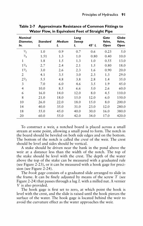
P1: JYC
GB098-02 GB098-Miller September 22, 2004 17:44 Char Count= 0
Principles of Hydraulics 91
Table 2-7 Approximate Resistance of Common Fittings toWater Flow, in Equivalent Feet of Straight Pipe
Nominal Long Gate GlobeDiameter, Standard Medium Sweep Valve, Valve,In. L L L 45◦ L Open Open
1/2 1.0 0.9 0.7 0.6 0.23 5.03/4 1.51 1.3 1.0 0.80 0.40 10.0
1 1.8 1.5 1.3 1.0 0.55 13.011/4 2.7 2.4 2.1 1.5 0.80 18.011/2 3.0 2.6 2.3 1.6 0.90 20.02 4.1 3.5 3.0 2.3 1.3 29.021/2 5.5 4.8 3.8 2.8 1.4 35.03 7.0 6.0 4.6 3.5 1.9 45.04 10.0 8.5 6.6 5.0 2.6 60.06 16.0 14.0 12.0 8.0 4.5 110.08 21.0 18.0 15.0 12.0 6.0 150.0
10 26.0 22.0 18.0 15.0 8.0 200.014 40.0 35.0 31.0 23.0 12.0 280.018 55.0 45.0 40.0 30.0 16.0 380.020 60.0 55.0 42.0 34.0 17.0 420.0
To construct a weir, a notched board is placed across a smallstream at some point, allowing a small pond to form. The notch inthe board should be beveled on both side edges and on the bottom.The bottom of the notch is called the crest of the weir. The crestshould be level and sides should be vertical.
A stake should be driven near the bank in the pond above theweir at a distance less than the width of the notch. The top ofthe stake should be level with the crest. The depth of the waterabove the top of the stake can be measured with a graduated rule(see Figure 2-23), or it can be measured with a hook gage for preci-sion (see Figure 2-24).
The hook gage consists of a graduated slide arranged to slide inthe frame. It can be finely adjusted by means of the screw T (seeFigure 2-24) that passes through a lug L with a milled nut. A vernierV is also provided.
The hook gage is first set to zero, at which point the hook islevel with the crest, and the slide is raised until the hook pierces thesurface of the water. The hook gage is located behind the weir toavoid the curvature effect as the water approaches the weir.
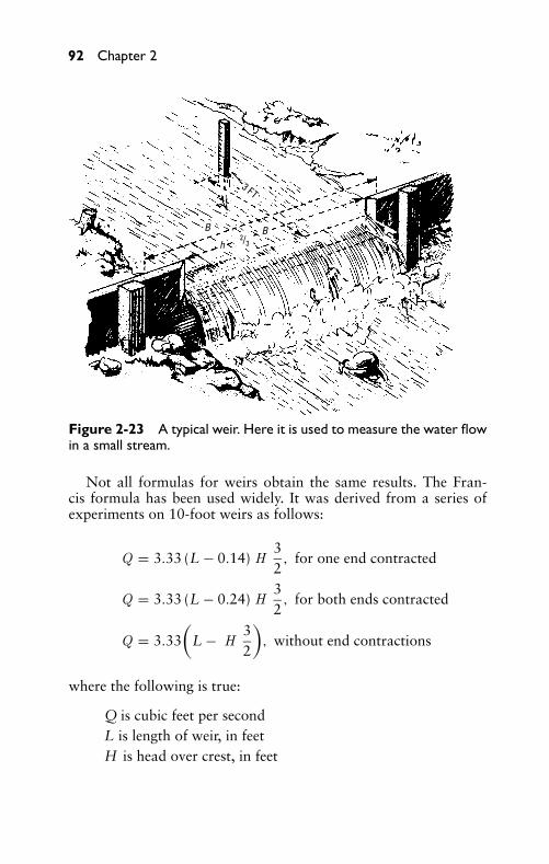
P1: JYC
GB098-02 GB098-Miller September 22, 2004 17:44 Char Count= 0
92 Chapter 2
3 FT
B Bh
2/3
Figure 2-23 A typical weir. Here it is used to measure the water flowin a small stream.
Not all formulas for weirs obtain the same results. The Fran-cis formula has been used widely. It was derived from a series ofexperiments on 10-foot weirs as follows:
Q = 3.33 (L − 0.14) H32
, for one end contracted
Q = 3.33 (L − 0.24) H32
, for both ends contracted
Q = 3.33(
L − H32
), without end contractions
where the following is true:
Q is cubic feet per secondL is length of weir, in feetH is head over crest, in feet
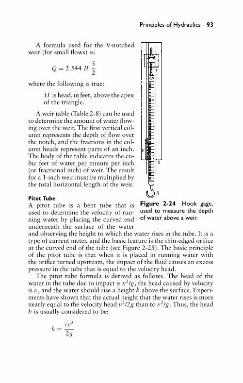
P1: JYC
GB098-02 GB098-Miller September 22, 2004 17:44 Char Count= 0
Principles of Hydraulics 93
L
T
V
S
H
Figure 2-24 Hook gage,used to measure the depthof water above a weir.
A formula used for the V-notchedweir (for small flows) is:
Q = 2.544 H52
where the following is true:
H is head, in feet, above the apexof the triangle.
A weir table (Table 2-8) can be usedto determine the amount of water flow-ing over the weir. The first vertical col-umn represents the depth of flow overthe notch, and the fractions in the col-umn heads represent parts of an inch.The body of the table indicates the cu-bic feet of water per minute per inch(or fractional inch) of weir. The resultfor a 1-inch weir must be multiplied bythe total horizontal length of the weir.
Pitot TubeA pitot tube is a bent tube that isused to determine the velocity of run-ning water by placing the curved endunderneath the surface of the waterand observing the height to which the water rises in the tube. It is atype of current meter, and the basic feature is the thin-edged orificeat the curved end of the tube (see Figure 2-25). The basic principleof the pitot tube is that when it is placed in running water withthe orifice turned upstream, the impact of the fluid causes an excesspressure in the tube that is equal to the velocity head.
The pitot tube formula is derived as follows. The head of thewater in the tube due to impact is v2/g , the head caused by velocityis v, and the water should rise a height h above the surface. Experi-ments have shown that the actual height that the water rises is morenearly equal to the velocity head v2/2g than to v2/g . Thus, the headh is usually considered to be:
h = cv2
2g
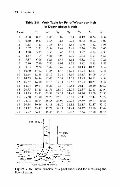
P1: JYC
GB098-02 GB098-Miller September 22, 2004 17:44 Char Count= 0
94 Chapter 2
Table 2-8 Weir Table for Ft3 of Water per Inchof Depth above Notch
Inches 1/8 1/4 3/8 1/2 5/8 3/4 7/8
0 0.00 0.01 0.05 0.09 0.14 0.19 0.26 0.321 0.40 0.47 0.55 0.64 0.73 0.82 0.92 1.022 1.13 1.23 1.35 1.46 1.58 1.70 1.82 1.953 2.07 2.21 2.34 2.48 2.61 2.76 2.90 3.054 3.20 3.35 3.50 3.66 3.81 3.97 4.14 4.305 4.47 4.64 4.81 4.98 5.15 5.33 5.51 5.696 5.87 6.06 6.25 6.44 6.62 6.82 7.01 7.217 7.40 7.60 7.80 8.01 8.21 8.42 8.63 8.838 9.05 9.26 9.47 9.69 9.91 10.13 10.35 10.579 10.80 11.02 11.25 11.48 11.71 11.94 12.17 12.41
10 12.64 12.88 13.12 13.36 13.60 13.85 14.09 14.3411 14.59 14.84 15.09 15.34 15.59 15.85 16.11 16.3612 16.62 16.88 17.15 17.41 17.67 17.94 18.21 18.4713 18.74 19.01 19.29 19.56 19.84 20.11 20.39 20.6714 20.95 21.23 21.51 21.80 22.08 22.37 22.65 22.9415 23.23 23.52 23.82 24.11 24.40 24.70 25.00 25.3016 25.60 25.90 26.20 26.50 26.80 27.11 27.42 27.7217 28.03 28.34 28.65 28.97 29.28 29.59 29.91 30.2118 30.54 30.86 31.18 31.50 31.82 32.15 32.47 32.8019 33.12 33.45 33.78 34.11 34.44 34.77 35.10 35.4420 35.77 36.11 36.45 36.78 37.12 37.46 37.80 38.15
h
V
ORIFICE
VELOCITYHEAD
FLOW VELOCITY AT ORIFICE
PITOT TUBE
Figure 2-25 Basic principle of a pitot tube, used for measuring theflow of water.
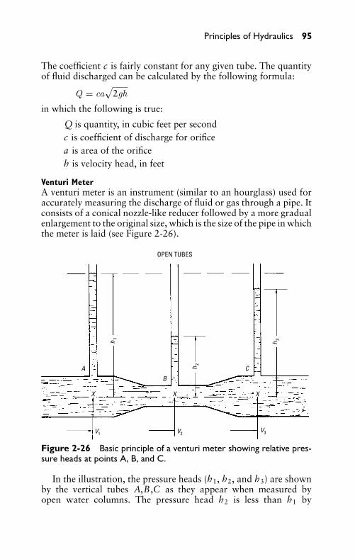
P1: JYC
GB098-02 GB098-Miller September 22, 2004 17:44 Char Count= 0
Principles of Hydraulics 95
The coefficient c is fairly constant for any given tube. The quantityof fluid discharged can be calculated by the following formula:
Q = ca√
2gh
in which the following is true:
Q is quantity, in cubic feet per secondc is coefficient of discharge for orificea is area of the orificeh is velocity head, in feet
Venturi MeterA venturi meter is an instrument (similar to an hourglass) used foraccurately measuring the discharge of fluid or gas through a pipe. Itconsists of a conical nozzle-like reducer followed by a more gradualenlargement to the original size, which is the size of the pipe in whichthe meter is laid (see Figure 2-26).
OPEN TUBES
CA
B
X X X
V1 V2
h3
h2
h1
V3
Figure 2-26 Basic principle of a venturi meter showing relative pres-sure heads at points A, B, and C.
In the illustration, the pressure heads (h1, h2, and h3) are shownby the vertical tubes A,B,C as they appear when measured byopen water columns. The pressure head h2 is less than h1 by
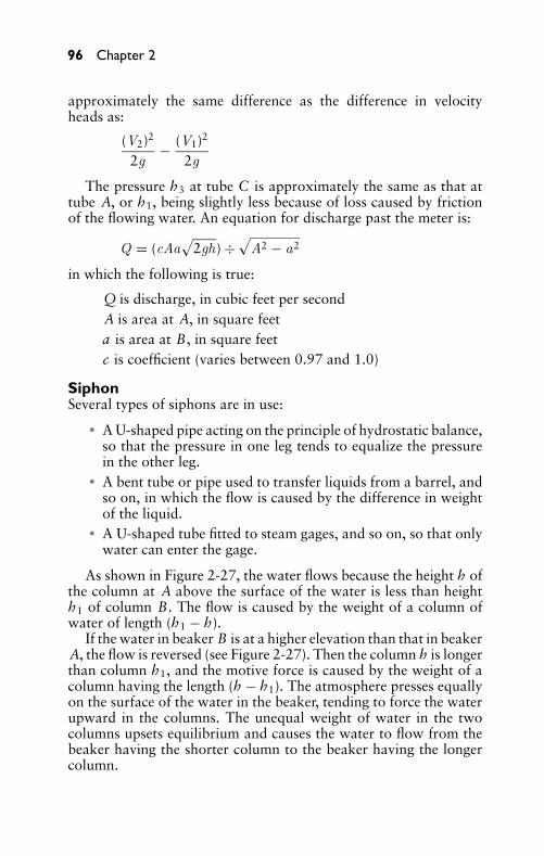
P1: JYC
GB098-02 GB098-Miller September 22, 2004 17:44 Char Count= 0
96 Chapter 2
approximately the same difference as the difference in velocityheads as:
(V2)2
2g− (V1)2
2g
The pressure h3 at tube C is approximately the same as that attube A, or h1, being slightly less because of loss caused by frictionof the flowing water. An equation for discharge past the meter is:
Q = (cAa√
2gh) ÷√
A2 − a2
in which the following is true:
Q is discharge, in cubic feet per secondA is area at A, in square feeta is area at B, in square feetc is coefficient (varies between 0.97 and 1.0)
SiphonSeveral types of siphons are in use:
� A U-shaped pipe acting on the principle of hydrostatic balance,so that the pressure in one leg tends to equalize the pressurein the other leg.
� A bent tube or pipe used to transfer liquids from a barrel, andso on, in which the flow is caused by the difference in weightof the liquid.
� A U-shaped tube fitted to steam gages, and so on, so that onlywater can enter the gage.
As shown in Figure 2-27, the water flows because the height h ofthe column at A above the surface of the water is less than heighth1 of column B. The flow is caused by the weight of a column ofwater of length (h1 − h).
If the water in beaker B is at a higher elevation than that in beakerA, the flow is reversed (see Figure 2-27). Then the column h is longerthan column h1, and the motive force is caused by the weight of acolumn having the length (h − h1). The atmosphere presses equallyon the surface of the water in the beaker, tending to force the waterupward in the columns. The unequal weight of water in the twocolumns upsets equilibrium and causes the water to flow from thebeaker having the shorter column to the beaker having the longercolumn.
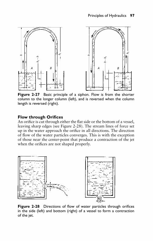
P1: JYC
GB098-02 GB098-Miller September 22, 2004 17:44 Char Count= 0
Principles of Hydraulics 97
A AB B
hh
h 1 − h
h 1
h −
h 1
h 1
Figure 2-27 Basic principle of a siphon. Flow is from the shortercolumn to the longer column (left), and is reversed when the columnlength is reversed (right).
Flow through OrificesAn orifice is cut through either the flat side or the bottom of a vessel,leaving sharp edges (see Figure 2-28). The stream lines of force setup in the water approach the orifice in all directions. The directionof flow of the water particles converges. This is with the exceptionof those near the center-point that produce a contraction of the jetwhen the orifices are not shaped properly.
Figure 2-28 Directions of flow of water particles through orificesin the side (left) and bottom (right) of a vessel to form a contractionof the jet.
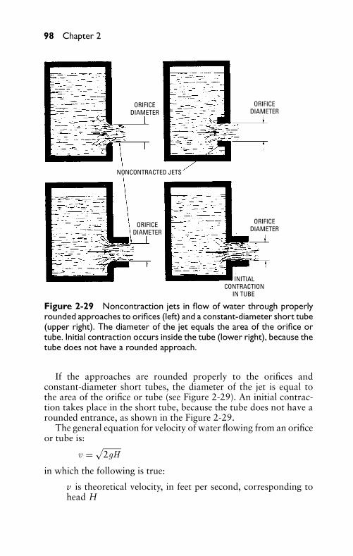
P1: JYC
GB098-02 GB098-Miller September 22, 2004 17:44 Char Count= 0
98 Chapter 2
ORIFICEDIAMETER
ORIFICEDIAMETER
ORIFICEDIAMETER
ORIFICEDIAMETER
NONCONTRACTED JETS
INITIALCONTRACTION
IN TUBE
Figure 2-29 Noncontraction jets in flow of water through properlyrounded approaches to orifices (left) and a constant-diameter short tube(upper right). The diameter of the jet equals the area of the orifice ortube. Initial contraction occurs inside the tube (lower right), because thetube does not have a rounded approach.
If the approaches are rounded properly to the orifices andconstant-diameter short tubes, the diameter of the jet is equal tothe area of the orifice or tube (see Figure 2-29). An initial contrac-tion takes place in the short tube, because the tube does not have arounded entrance, as shown in the Figure 2-29.
The general equation for velocity of water flowing from an orificeor tube is:
v =√
2gH
in which the following is true:
v is theoretical velocity, in feet per second, corresponding tohead H
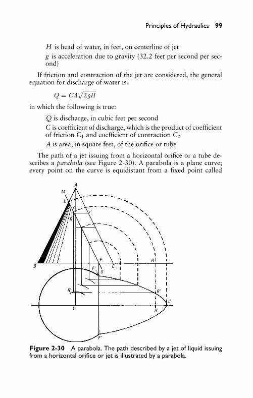
P1: JYC
GB098-02 GB098-Miller September 22, 2004 17:44 Char Count= 0
Principles of Hydraulics 99
H is head of water, in feet, on centerline of jetg is acceleration due to gravity (32.2 feet per second per sec-ond)
If friction and contraction of the jet are considered, the generalequation for discharge of water is:
Q = CA√
2gH
in which the following is true:
Q is discharge, in cubic feet per secondC is coefficient of discharge, which is the product of coefficientof friction C1 and coefficient of contraction C2
A is area, in square feet, of the orifice or tube
The path of a jet issuing from a horizontal orifice or a tube de-scribes a parabola (see Figure 2-30). A parabola is a plane curve;every point on the curve is equidistant from a fixed point called
A
B CF
F 'S
R'
G
L'
R "
H
R
rr '
L
M
F "
O
Figure 2-30 A parabola. The path described by a jet of liquid issuingfrom a horizontal orifice or jet is illustrated by a parabola.
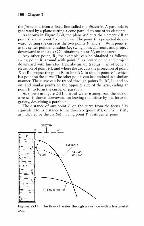
P1: JYC
GB098-02 GB098-Miller September 22, 2004 17:44 Char Count= 0
100 Chapter 2
the focus and from a fixed line called the directrix. A parabola isgenerated by a plane cutting a cone parallel to one of its elements.
As shown in Figure 2-30, the plane MS cuts the element AB atpoint L and at point F on the base. The point F is projected down-ward, cutting the curve at the two points F ′ and F ′′. With point Fas the center point and radius LF, swing point L around and projectdownward to the axis OG, obtaining point L′, on the curve.
Any other point, R , for example, can be obtained as follows:swing point R around with point F as center point and projectdownward with line HG. Describe an arc (radius = rr′ of cone atelevation of point R), and where the arc cuts the projection of pointR at R′, project the point R′ to line HG to obtain point R ′′, whichis a point on the curve. The other points can be obtained in a similarmanner. The curve can be traced through points F′, R′′, L′, and soon, and similar points on the opposite side of the axis, ending atpoint F′′ to form the curve, or parabola.
As shown in Figure 2-31, a jet of water issuing from the side ofa vessel is drawn downward on leaving the orifice by the force ofgravity, describing a parabola.
The distance of any point P on the curve from the focus S isequivalent to its distance to the directrix (point M), or P S = P M,as indicated by the arc SM, having point P as its center point.
DIRECTRIX
O
FOCUS
STREAM OF WATER
PARABOLA
AXIS
A
S
P
M
OA = ASSP = PM
Figure 2-31 The flow of water through an orifice with a horizontalaxis.
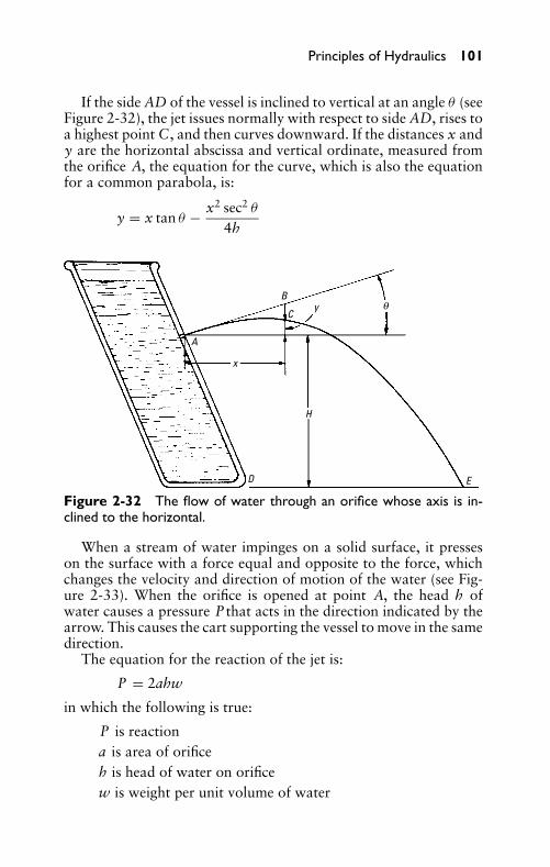
P1: JYC
GB098-02 GB098-Miller September 22, 2004 17:44 Char Count= 0
Principles of Hydraulics 101
If the side AD of the vessel is inclined to vertical at an angle θ (seeFigure 2-32), the jet issues normally with respect to side AD, rises toa highest point C, and then curves downward. If the distances x andy are the horizontal abscissa and vertical ordinate, measured fromthe orifice A, the equation for the curve, which is also the equationfor a common parabola, is:
y = x tan θ − x2 sec2 θ
4h
B
A
C
H
ED
y q
x
Figure 2-32 The flow of water through an orifice whose axis is in-clined to the horizontal.
When a stream of water impinges on a solid surface, it presseson the surface with a force equal and opposite to the force, whichchanges the velocity and direction of motion of the water (see Fig-ure 2-33). When the orifice is opened at point A, the head h ofwater causes a pressure P that acts in the direction indicated by thearrow. This causes the cart supporting the vessel to move in the samedirection.
The equation for the reaction of the jet is:
P = 2ahw
in which the following is true:
P is reactiona is area of orificeh is head of water on orificew is weight per unit volume of water
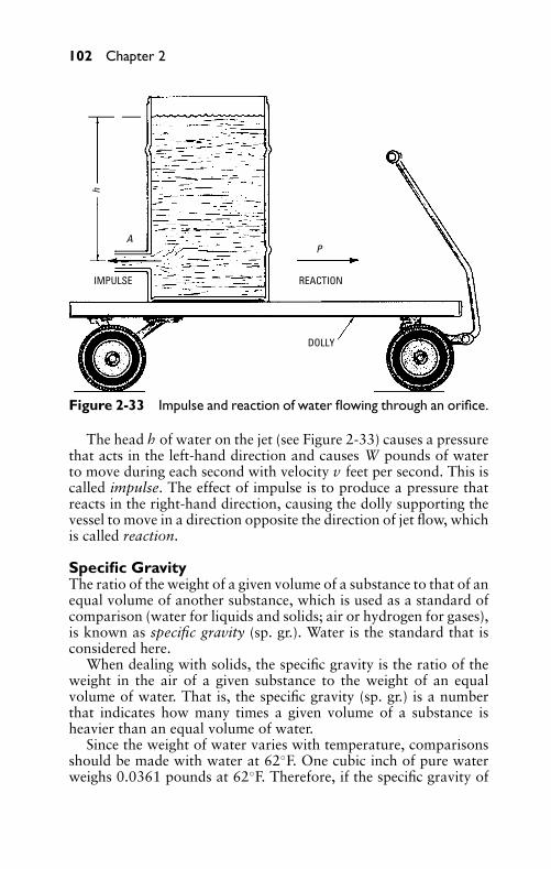
P1: JYC
GB098-02 GB098-Miller September 22, 2004 17:44 Char Count= 0
102 Chapter 2
h
AP
IMPULSE REACTION
DOLLY
Figure 2-33 Impulse and reaction of water flowing through an orifice.
The head h of water on the jet (see Figure 2-33) causes a pressurethat acts in the left-hand direction and causes W pounds of waterto move during each second with velocity v feet per second. This iscalled impulse. The effect of impulse is to produce a pressure thatreacts in the right-hand direction, causing the dolly supporting thevessel to move in a direction opposite the direction of jet flow, whichis called reaction.
Specific GravityThe ratio of the weight of a given volume of a substance to that of anequal volume of another substance, which is used as a standard ofcomparison (water for liquids and solids; air or hydrogen for gases),is known as specific gravity (sp. gr.). Water is the standard that isconsidered here.
When dealing with solids, the specific gravity is the ratio of theweight in the air of a given substance to the weight of an equalvolume of water. That is, the specific gravity (sp. gr.) is a numberthat indicates how many times a given volume of a substance isheavier than an equal volume of water.
Since the weight of water varies with temperature, comparisonsshould be made with water at 62◦F. One cubic inch of pure waterweighs 0.0361 pounds at 62◦F. Therefore, if the specific gravity of
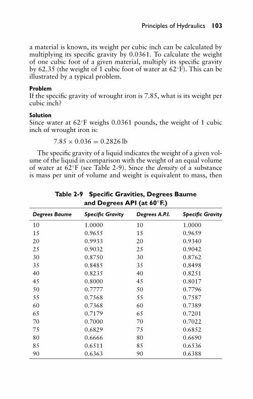
P1: JYC
GB098-02 GB098-Miller September 22, 2004 17:44 Char Count= 0
Principles of Hydraulics 103
a material is known, its weight per cubic inch can be calculated bymultiplying its specific gravity by 0.0361. To calculate the weightof one cubic foot of a given material, multiply its specific gravityby 62.35 (the weight of 1 cubic foot of water at 62◦F). This can beillustrated by a typical problem.
ProblemIf the specific gravity of wrought iron is 7.85, what is its weight percubic inch?
SolutionSince water at 62◦F weighs 0.0361 pounds, the weight of 1 cubicinch of wrought iron is:
7.85 × 0.036 = 0.2826 lb
The specific gravity of a liquid indicates the weight of a given vol-ume of the liquid in comparison with the weight of an equal volumeof water at 62◦F (see Table 2-9). Since the density of a substanceis mass per unit of volume and weight is equivalent to mass, then
Table 2-9 Specific Gravities, Degrees Baumeand Degrees API (at 60◦F.)
Degrees Baume Specific Gravity Degrees A.P.I. Specific Gravity
10 1.0000 10 1.000015 0.9655 15 0.965920 0.9933 20 0.934025 0.9032 25 0.904230 0.8750 30 0.876235 0.8485 35 0.849840 0.8235 40 0.825145 0.8000 45 0.801750 0.7777 50 0.779655 0.7568 55 0.758760 0.7368 60 0.738965 0.7179 65 0.720170 0.7000 70 0.702275 0.6829 75 0.685280 0.6666 80 0.669085 0.6511 85 0.653690 0.6363 90 0.6388
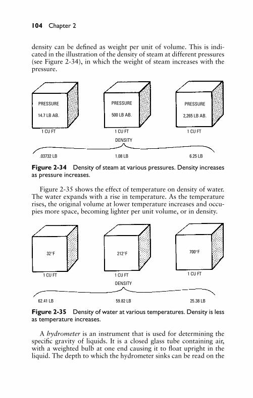
P1: JYC
GB098-02 GB098-Miller September 22, 2004 17:44 Char Count= 0
104 Chapter 2
density can be defined as weight per unit of volume. This is indi-cated in the illustration of the density of steam at different pressures(see Figure 2-34), in which the weight of steam increases with thepressure.
PRESSURE
500 LB AB.
PRESSURE
2,265 LB AB.
PRESSURE
14.7 LB AB.
1 CU FT 1 CU FT 1 CU FT
DENSITY
.03732 LB 1.08 LB 6.25 LB
Figure 2-34 Density of steam at various pressures. Density increasesas pressure increases.
Figure 2-35 shows the effect of temperature on density of water.The water expands with a rise in temperature. As the temperaturerises, the original volume at lower temperature increases and occu-pies more space, becoming lighter per unit volume, or in density.
32°F 212°F 700°F
1 CU FT 1 CU FT 1 CU FT
62.41 LB 59.82 LB 25.38 LB
DENSITY
Figure 2-35 Density of water at various temperatures. Density is lessas temperature increases.
A hydrometer is an instrument that is used for determining thespecific gravity of liquids. It is a closed glass tube containing air,with a weighted bulb at one end causing it to float upright in theliquid. The depth to which the hydrometer sinks can be read on the
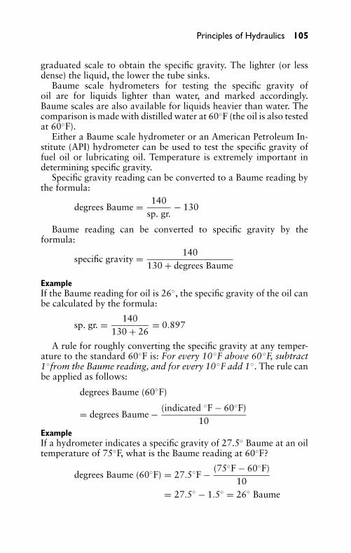
P1: JYC
GB098-02 GB098-Miller September 22, 2004 17:44 Char Count= 0
Principles of Hydraulics 105
graduated scale to obtain the specific gravity. The lighter (or lessdense) the liquid, the lower the tube sinks.
Baume scale hydrometers for testing the specific gravity ofoil are for liquids lighter than water, and marked accordingly.Baume scales are also available for liquids heavier than water. Thecomparison is made with distilled water at 60◦F (the oil is also testedat 60◦F).
Either a Baume scale hydrometer or an American Petroleum In-stitute (API) hydrometer can be used to test the specific gravity offuel oil or lubricating oil. Temperature is extremely important indetermining specific gravity.
Specific gravity reading can be converted to a Baume reading bythe formula:
degrees Baume = 140sp. gr.
− 130
Baume reading can be converted to specific gravity by theformula:
specific gravity = 140130 + degrees Baume
ExampleIf the Baume reading for oil is 26◦, the specific gravity of the oil canbe calculated by the formula:
sp. gr. = 140130 + 26
= 0.897
A rule for roughly converting the specific gravity at any temper-ature to the standard 60◦F is: For every 10◦F above 60◦F, subtract1◦from the Baume reading, and for every 10◦F add 1◦. The rule canbe applied as follows:
degrees Baume (60◦F)
= degrees Baume − (indicated ◦F − 60◦F)10
ExampleIf a hydrometer indicates a specific gravity of 27.5◦ Baume at an oiltemperature of 75◦F, what is the Baume reading at 60◦F?
degrees Baume (60◦F) = 27.5◦F − (75◦F − 60◦F)10
= 27.5◦ − 1.5◦ = 26◦ Baume
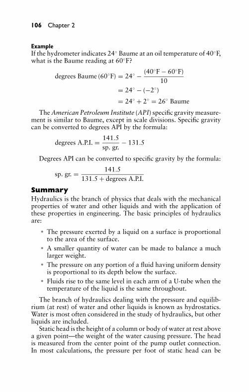
P1: JYC
GB098-02 GB098-Miller September 22, 2004 17:44 Char Count= 0
106 Chapter 2
ExampleIf the hydrometer indicates 24◦ Baume at an oil temperature of 40◦F,what is the Baume reading at 60◦F?
degrees Baume (60◦F) = 24◦ − (40◦F − 60◦F)10
= 24◦ − (−2◦)
= 24◦ + 2◦ = 26◦ Baume
The American Petroleum Institute (API) specific gravity measure-ment is similar to Baume, except in scale divisions. Specific gravitycan be converted to degrees API by the formula:
degrees A.P.I. = 141.5sp. gr.
− 131.5
Degrees API can be converted to specific gravity by the formula:
sp. gr. = 141.5131.5 + degrees A.P.I.
SummaryHydraulics is the branch of physics that deals with the mechanicalproperties of water and other liquids and with the application ofthese properties in engineering. The basic principles of hydraulicsare:
� The pressure exerted by a liquid on a surface is proportionalto the area of the surface.
� A smaller quantity of water can be made to balance a muchlarger weight.
� The pressure on any portion of a fluid having uniform densityis proportional to its depth below the surface.
� Fluids rise to the same level in each arm of a U-tube when thetemperature of the liquid is the same throughout.
The branch of hydraulics dealing with the pressure and equilib-rium (at rest) of water and other liquids is known as hydrostatics.Water is most often considered in the study of hydraulics, but otherliquids are included.
Static head is the height of a column or body of water at rest abovea given point—the weight of the water causing pressure. The headis measured from the center point of the pump outlet connection.In most calculations, the pressure per foot of static head can be
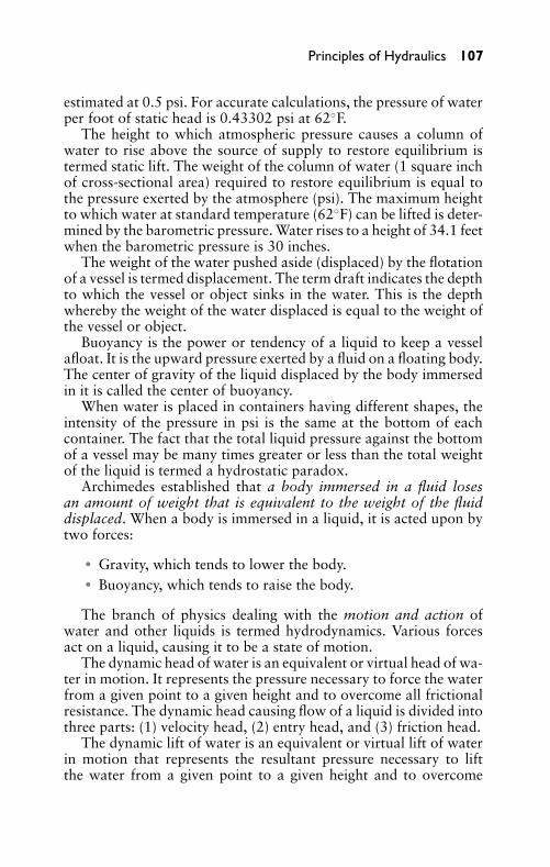
P1: JYC
GB098-02 GB098-Miller September 22, 2004 17:44 Char Count= 0
Principles of Hydraulics 107
estimated at 0.5 psi. For accurate calculations, the pressure of waterper foot of static head is 0.43302 psi at 62◦F.
The height to which atmospheric pressure causes a column ofwater to rise above the source of supply to restore equilibrium istermed static lift. The weight of the column of water (1 square inchof cross-sectional area) required to restore equilibrium is equal tothe pressure exerted by the atmosphere (psi). The maximum heightto which water at standard temperature (62◦F) can be lifted is deter-mined by the barometric pressure. Water rises to a height of 34.1 feetwhen the barometric pressure is 30 inches.
The weight of the water pushed aside (displaced) by the flotationof a vessel is termed displacement. The term draft indicates the depthto which the vessel or object sinks in the water. This is the depthwhereby the weight of the water displaced is equal to the weight ofthe vessel or object.
Buoyancy is the power or tendency of a liquid to keep a vesselafloat. It is the upward pressure exerted by a fluid on a floating body.The center of gravity of the liquid displaced by the body immersedin it is called the center of buoyancy.
When water is placed in containers having different shapes, theintensity of the pressure in psi is the same at the bottom of eachcontainer. The fact that the total liquid pressure against the bottomof a vessel may be many times greater or less than the total weightof the liquid is termed a hydrostatic paradox.
Archimedes established that a body immersed in a fluid losesan amount of weight that is equivalent to the weight of the fluiddisplaced. When a body is immersed in a liquid, it is acted upon bytwo forces:
� Gravity, which tends to lower the body.� Buoyancy, which tends to raise the body.
The branch of physics dealing with the motion and action ofwater and other liquids is termed hydrodynamics. Various forcesact on a liquid, causing it to be a state of motion.
The dynamic head of water is an equivalent or virtual head of wa-ter in motion. It represents the pressure necessary to force the waterfrom a given point to a given height and to overcome all frictionalresistance. The dynamic head causing flow of a liquid is divided intothree parts: (1) velocity head, (2) entry head, and (3) friction head.
The dynamic lift of water is an equivalent or virtual lift of waterin motion that represents the resultant pressure necessary to liftthe water from a given point to a given height and to overcome
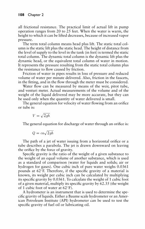
P1: JYC
GB098-02 GB098-Miller September 22, 2004 17:44 Char Count= 0
108 Chapter 2
all frictional resistance. The practical limit of actual lift in pumpoperation ranges from 20 to 25 feet. When the water is warm, theheight to which it can be lifted decreases, because of increased vaporpressure.
The term total column means head plus lift. The static total col-umn is the static lift plus the static head. The height of distance fromthe level of supply to the level in the tank (in feet) is termed the statictotal column. The dynamic total column is the dynamic lift plus thedynamic head, or the equivalent total column of water in motion.It represents the pressure resulting from the static total column plusthe resistance to flow caused by friction.
Friction of water in pipes results in loss of pressure and reducedvolume of water per minute delivered. Also, friction in the faucets,in the fitting, and in the flow through the meter must be considered.
Water flow can be measured by means of the weir, pitot tube,and venturi meter. Actual measurements of the volume and of theweight of the liquid delivered may be more accurate, but they canbe used only when the quantity of water delivered is small.
The general equation for velocity of water flowing from an orificeor tube is:
V =√
2gh
The general equation for discharge of water through an orifice is:
Q = ca√
2gh
The path of a jet of water issuing from a horizontal orifice or atube describes a parabola. The jet is drawn downward on leavingthe orifice by the force of gravity.
Specific gravity is the ratio of the weight of a given substance tothe weight of an equal volume of another substance, which is usedas a standard of comparison (water for liquids and solids; air orhydrogen for gases). One cubic inch of pure water weighs 0.0361pounds at 62◦F. Therefore, if the specific gravity of a material isknown, its weight per cubic inch can be calculated by multiplyingits specific gravity by 0.0361. To calculate the weight of 1 cubic footof a given material, multiply its specific gravity by 62.35 (the weightof 1 cubic foot of water at 62◦F).
A hydrometer is an instrument that is used to determine the spe-cific gravity of liquids. Either a Baume scale hydrometer or an Amer-ican Petroleum Institute (API) hydrometer can be used to test thespecific gravity of fuel oil or lubricating oil.
P1: JYC
GB098-02 GB098-Miller September 22, 2004 17:44 Char Count= 0
Principles of Hydraulics 109
A specific gravity reading can be converted to a Baume readingby the following formula:
degrees Baume = 140sp. gr.
− 130
Specific gravity reading can be converted to degrees API by thefollowing formula:
degrees A.P.I. = 141.5sp. gr.
− 131.5
Degrees API can be converted to specific gravity by the followingformula:
sp. gr. = 141.5131.5 + degrees A.P.I.
Review Questions1. What is hydraulics?2. List four important principles of hydraulics.3. What is meant by a head of water?4. What is meant by lift, hydraulically?5. What is the difference between static head and dynamic
head?6. What is the difference between static lift and dynamic lift?7. What is the maximum height to which atmospheric pressure
can lift water?8. What factor determines the maximum height to which water
is lifted at standard temperature (62◦F)?9. To what depth does an object sink in water?
10. What is buoyancy?11. What is the practical limit of pump operation? Why?12. What is meant by total column of water?13. What is the effect of friction in pipes, fittings, and so on?14. Name three instruments for measuring the flow of water.15. Explain how a siphon operates.16. What is meant by specific gravity of a substance?17. Explain the basic principle of a hydrometer.
P1: JYC
GB098-02 GB098-Miller September 22, 2004 17:44 Char Count= 0
110 Chapter 2
18. When did the fundamental law evolve for the science of hy-draulics?
19. What is hydrostatics?20. Define displacement.21. Define draft.22. What is Archimedes’ Principle?23. Define hydrostatic paradox.24. When is hydrostatic balance achieved?25. What is that branch of physics dealing with the motion and
action of water and other liquids called?26. What is meant by the term negative lift? What is another name
for this term?27. What causes a difference between actual lift and static lift?28. Why must pumps handling water at high temperature work
on reduced actual lift?29. If you have a 1/2-inch commercial faucet with a rate of flow
of 10 gallons per minute what would be the loss in pressurecaused by the faucet?
30. What four factors determine the quantity of water dischargedthrough a pipe?
31. What is the approximate resistance to water flow of a 45◦F Lfitting that has a nominal diameter of 3 inches?
32. What is a hook gage? How does it work?33. Sketch a venturi meter and identify the various points.34. How does a siphon work?35. What is the specific gravity at 35◦ Baume?36. What is the specific gravity at 60◦API?37. What does API stand for?38. What is the general equation for velocity of water flowing from
an orifice or tube?39. What is the term parabola used to describe?
P1: FCH
GB098-03 GB098-Miller September 13, 2004 17:50 Char Count= 0
Part II
Pumps
111

P1: FCH
GB098-03 GB098-Miller September 13, 2004 17:50 Char Count= 0
112
P1: FCH
GB098-03 GB098-Miller September 13, 2004 17:50 Char Count= 0
Chapter 3Centrifugal PumpsAll types of centrifugal pumps depend on centrifugal force for theiroperation. Centrifugal force acts on a body moving in a circularpath, tending to force it farther away from the axis or center pointof the circle described by the path of the rotating body.
Basic PrinciplesThe rotating member inside the casing of a centrifugal pump pro-vides rapid rotary motion to the mass of water contained in thecasing. That means the water is forced out of the housing throughthe discharge outlet by means of centrifugal force. The vacuum cre-ated thereby enables atmospheric pressure to force more water intothe casing through the inlet opening. This process continues as longas motion is provided to the rotor, and as long as a supply of wateris available. In the centrifugal pump, vanes or impellers rotating in-side a close-fitting housing draw the liquid into the pump through acentral inlet opening, and by means of centrifugal force the liquid isthrown outward through a discharge outlet at the periphery of thehousing.
Figure 3-1 and Figure 3-2 show the basic principle of centrifu-gal pump operation. If a cylindrical can with vanes A and C (forrotating the liquid when the can is rotated) is mounted on a shaftwith a pulley for rotating the can at high speed, centrifugal forceacts on the water (rotating at high speed) to press the water out-ward to the walls of the can. This causes the water to press outwardsharply. Since it cannot move beyond the walls of the can, pres-sure forces the water upward, causing it to overflow as the waternear the center of the can is drawn downward. Atmospheric pres-sure forces the water downward, since a vacuum is created nearthe center as the water moves outward toward the sides of the can.It can be noted in Figure 3-1 that the water has been lifted a dis-tance DD′.
Since the water that spills over the top has a high velocity that isequal to the rim speed, the kinetic energy that has been generatedis wasted, unless an arrangement is made to catch the water and anadditional supply of water is provided (see Figure 3-2). In Figure 3-2,a receiver catches the water as it spills over, and a supply tank isconnected with the hollow shaft to supply water to the can. Insteadof rotating the can, only the vanes can be rotated to obtain the sameresult.
113
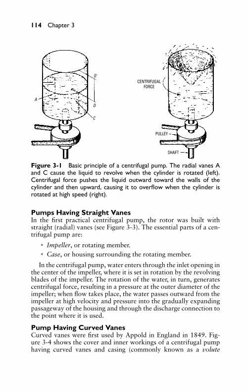
P1: FCH
GB098-03 GB098-Miller September 13, 2004 17:50 Char Count= 0
114 Chapter 3
CENTRIFUGALFORCE
PULLEY
SHAFT
AD
C
D'
Figure 3-1 Basic principle of a centrifugal pump. The radial vanes Aand C cause the liquid to revolve when the cylinder is rotated (left).Centrifugal force pushes the liquid outward toward the walls of thecylinder and then upward, causing it to overflow when the cylinder isrotated at high speed (right).
Pumps Having Straight VanesIn the first practical centrifugal pump, the rotor was built withstraight (radial) vanes (see Figure 3-3). The essential parts of a cen-trifugal pump are:
� Impeller, or rotating member.� Case, or housing surrounding the rotating member.
In the centrifugal pump, water enters through the inlet opening inthe center of the impeller, where it is set in rotation by the revolvingblades of the impeller. The rotation of the water, in turn, generatescentrifugal force, resulting in a pressure at the outer diameter of theimpeller; when flow takes place, the water passes outward from theimpeller at high velocity and pressure into the gradually expandingpassageway of the housing and through the discharge connection tothe point where it is used.
Pump Having Curved VanesCurved vanes were first used by Appold in England in 1849. Fig-ure 3-4 shows the cover and inner workings of a centrifugal pumphaving curved vanes and casing (commonly known as a volute
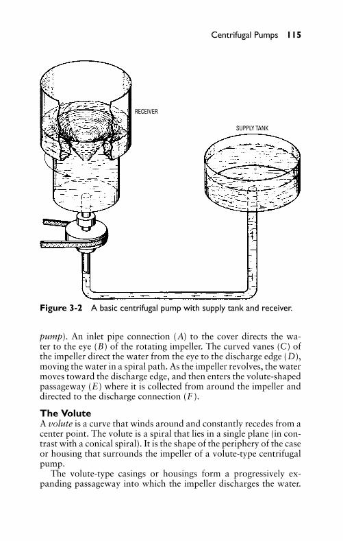
P1: FCH
GB098-03 GB098-Miller September 13, 2004 17:50 Char Count= 0
Centrifugal Pumps 115
RECEIVER
SUPPLY TANK
Figure 3-2 A basic centrifugal pump with supply tank and receiver.
pump). An inlet pipe connection (A) to the cover directs the wa-ter to the eye (B) of the rotating impeller. The curved vanes (C) ofthe impeller direct the water from the eye to the discharge edge (D),moving the water in a spiral path. As the impeller revolves, the watermoves toward the discharge edge, and then enters the volute-shapedpassageway (E) where it is collected from around the impeller anddirected to the discharge connection (F ).
The VoluteA volute is a curve that winds around and constantly recedes from acenter point. The volute is a spiral that lies in a single plane (in con-trast with a conical spiral). It is the shape of the periphery of the caseor housing that surrounds the impeller of a volute-type centrifugalpump.
The volute-type casings or housings form a progressively ex-panding passageway into which the impeller discharges the water.
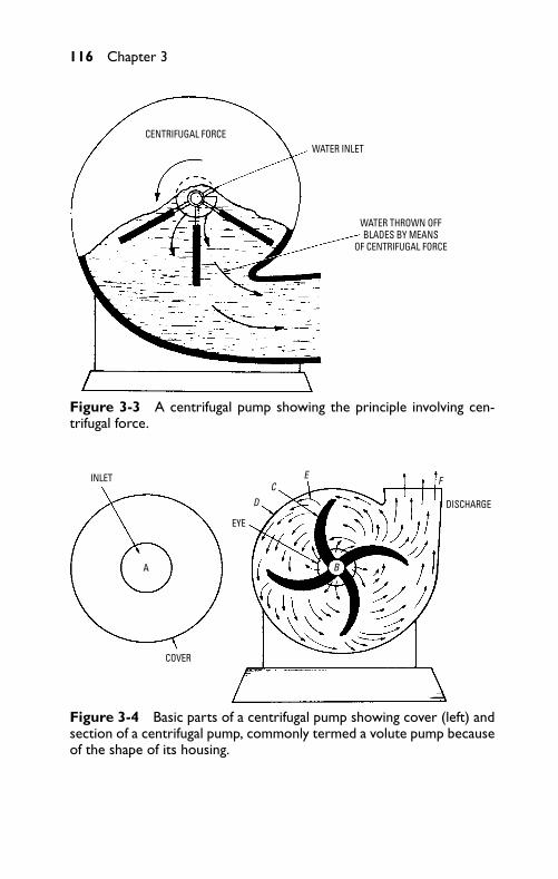
P1: FCH
GB098-03 GB098-Miller September 13, 2004 17:50 Char Count= 0
116 Chapter 3
CENTRIFUGAL FORCEWATER INLET
WATER THROWN OFFBLADES BY MEANS
OF CENTRIFUGAL FORCE
Figure 3-3 A centrifugal pump showing the principle involving cen-trifugal force.
INLET
COVER
EYE
D
A
CE F
B
DISCHARGE
Figure 3-4 Basic parts of a centrifugal pump showing cover (left) andsection of a centrifugal pump, commonly termed a volute pump becauseof the shape of its housing.
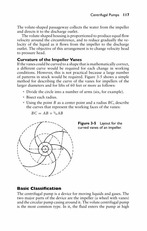
P1: FCH
GB098-03 GB098-Miller September 13, 2004 17:50 Char Count= 0
Centrifugal Pumps 117
The volute-shaped passageway collects the water from the impellerand directs it to the discharge outlet.
The volute-shaped housing is proportioned to produce equal flowvelocity around the circumference, and to reduce gradually the ve-locity of the liquid as it flows from the impeller to the dischargeoutlet. The objective of this arrangement is to change velocity headto pressure head.
Curvature of the Impeller VanesIf the vanes could be curved to a shape that is mathematically correct,a different curve would be required for each change in workingconditions. However, this is not practical because a large numberof patterns in stock would be required. Figure 3-5 shows a simplemethod for describing the curve of the vanes for impellers of thelarger diameters and for lifts of 60 feet or more as follows:
� Divide the circle into a number of arms (six, for example).� Bisect each radius.� Using the point B as a center point and a radius BC, describe
the curves that represent the working faces of the vanes:
BC = AB + 1/6AB
A B
C
Figure 3-5 Layout for thecurved vanes of an impeller.
Basic ClassificationThe centrifugal pump is a device for moving liquids and gases. Thetwo major parts of the device are the impeller (a wheel with vanes)and the circular pump casing around it. The volute centrifugal pumpis the most common type. In it, the fluid enters the pump at high
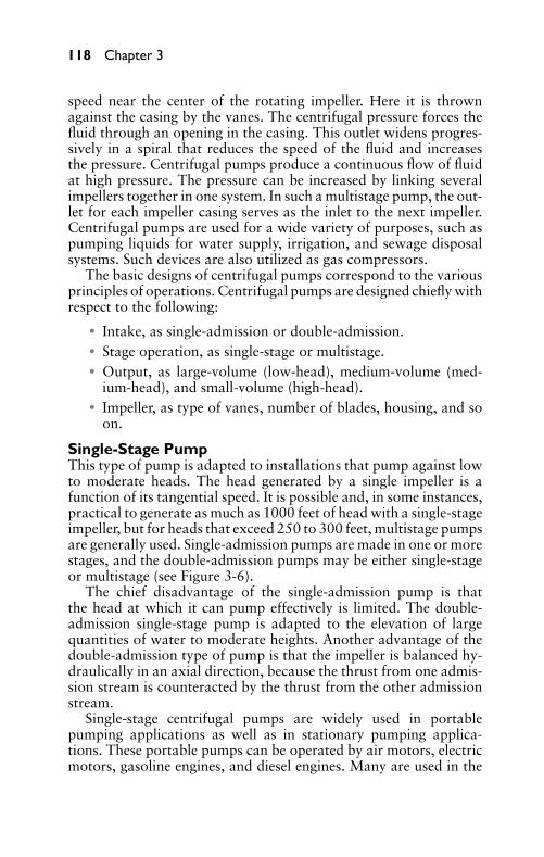
P1: FCH
GB098-03 GB098-Miller September 13, 2004 17:50 Char Count= 0
118 Chapter 3
speed near the center of the rotating impeller. Here it is thrownagainst the casing by the vanes. The centrifugal pressure forces thefluid through an opening in the casing. This outlet widens progres-sively in a spiral that reduces the speed of the fluid and increasesthe pressure. Centrifugal pumps produce a continuous flow of fluidat high pressure. The pressure can be increased by linking severalimpellers together in one system. In such a multistage pump, the out-let for each impeller casing serves as the inlet to the next impeller.Centrifugal pumps are used for a wide variety of purposes, such aspumping liquids for water supply, irrigation, and sewage disposalsystems. Such devices are also utilized as gas compressors.
The basic designs of centrifugal pumps correspond to the variousprinciples of operations. Centrifugal pumps are designed chiefly withrespect to the following:
� Intake, as single-admission or double-admission.� Stage operation, as single-stage or multistage.� Output, as large-volume (low-head), medium-volume (med-
ium-head), and small-volume (high-head).� Impeller, as type of vanes, number of blades, housing, and so
on.
Single-Stage PumpThis type of pump is adapted to installations that pump against lowto moderate heads. The head generated by a single impeller is afunction of its tangential speed. It is possible and, in some instances,practical to generate as much as 1000 feet of head with a single-stageimpeller, but for heads that exceed 250 to 300 feet, multistage pumpsare generally used. Single-admission pumps are made in one or morestages, and the double-admission pumps may be either single-stageor multistage (see Figure 3-6).
The chief disadvantage of the single-admission pump is thatthe head at which it can pump effectively is limited. The double-admission single-stage pump is adapted to the elevation of largequantities of water to moderate heights. Another advantage of thedouble-admission type of pump is that the impeller is balanced hy-draulically in an axial direction, because the thrust from one admis-sion stream is counteracted by the thrust from the other admissionstream.
Single-stage centrifugal pumps are widely used in portablepumping applications as well as in stationary pumping applica-tions. These portable pumps can be operated by air motors, electricmotors, gasoline engines, and diesel engines. Many are used in the
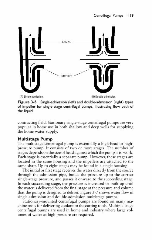
P1: FCH
GB098-03 GB098-Miller September 13, 2004 17:50 Char Count= 0
Centrifugal Pumps 119
CASING
IMPELLER
(A) Single admission. (B) Double admission.
Figure 3-6 Single-admission (left) and double-admission (right) typesof impeller for single-stage centrifugal pumps, illustrating flow path ofthe liquid.
contracting field. Stationary single-stage centrifugal pumps are verypopular in home use in both shallow and deep wells for supplyingthe home water supply.
Multistage PumpThe multistage centrifugal pump is essentially a high-head or high-pressure pump. It consists of two or more stages. The number ofstages depends on the size of head against which the pump is to work.Each stage is essentially a separate pump. However, these stages arelocated in the same housing and the impellers are attached to thesame shaft. Up to eight stages may be found in a single housing.
The initial or first stage receives the water directly from the sourcethrough the admission pipe, builds the pressure up to the correctsingle-stage pressure, and passes it onward to the succeeding stage.In each succeeding stage, the pressure is increased or built up untilthe water is delivered from the final stage at the pressure and volumethat the pump is designed to deliver. Figure 3-7 shows water flow insingle-admission and double-admission multistage pumps.
Stationary-mounted centrifugal pumps are found on many ma-chine tools for delivering coolant to the cutting tools. Multiple-stagecentrifugal pumps are used in home and industry where large vol-umes of water at high pressure are required.
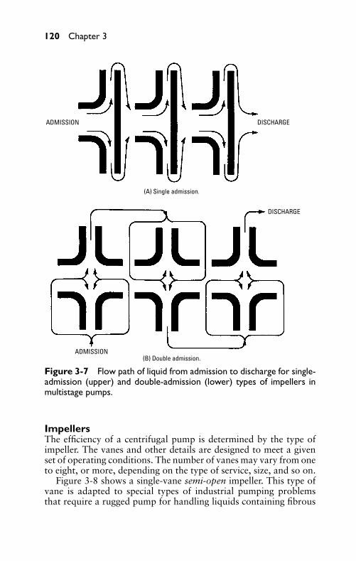
P1: FCH
GB098-03 GB098-Miller September 13, 2004 17:50 Char Count= 0
120 Chapter 3
(A) Single admission.
(B) Double admission.ADMISSION
ADMISSION DISCHARGE
DISCHARGE
Figure 3-7 Flow path of liquid from admission to discharge for single-admission (upper) and double-admission (lower) types of impellers inmultistage pumps.
ImpellersThe efficiency of a centrifugal pump is determined by the type ofimpeller. The vanes and other details are designed to meet a givenset of operating conditions. The number of vanes may vary from oneto eight, or more, depending on the type of service, size, and so on.
Figure 3-8 shows a single-vane semi-open impeller. This type ofvane is adapted to special types of industrial pumping problemsthat require a rugged pump for handling liquids containing fibrous
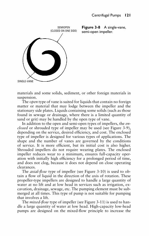
P1: FCH
GB098-03 GB098-Miller September 13, 2004 17:50 Char Count= 0
Centrifugal Pumps 121
SEMIOPEN(CLOSED ON ONE SIDE)
SINGLE-VANE
Figure 3-8 A single-vane,semi-open impeller.
materials and some solids, sediment, or other foreign materials insuspension.
The open type of vane is suited for liquids that contain no foreignmatter or material that may lodge between the impeller and thestationary side plates. Liquids containing some solids (such as thosefound in sewage or drainage, where there is a limited quantity ofsand or grit) may be handled by the open type of vane.
In addition to the open and semi-open types of impellers, the en-closed or shrouded type of impeller may be used (see Figure 3-9),depending on the service, desired efficiency, and cost. The enclosedtype of impeller is designed for various types of applications. Theshape and the number of vanes are governed by the conditionsof service. It is more efficient, but its initial cost is also higher.Shrouded impellers do not require wearing plates. The enclosedimpeller reduces wear to a minimum, ensures full-capacity oper-ation with initially high efficiency for a prolonged period of time,and does not clog, because it does not depend on close operatingclearances.
The axial-flow type of impeller (see Figure 3-10) is used to ob-tain a flow of liquid in the direction of the axis of rotation. Thesepropeller-type impellers are designed to handle a large quantity ofwater at no lift and at low head in services such as irrigation, ex-cavation, drainage, sewage, etc. The pumping element must be sub-merged at all times. This type of pump is not suitable for pumpingthat involves a lift.
The mixed-flow type of impeller (see Figure 3-11) is used to han-dle a large quantity of water at low head. High-capacity low-headpumps are designed on the mixed-flow principle to increase the
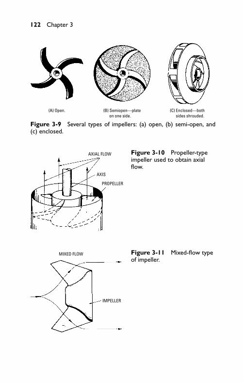
P1: FCH
GB098-03 GB098-Miller September 13, 2004 17:50 Char Count= 0
122 Chapter 3
(A) Open. (B) Semiopen—plate on one side.
(C) Enclosed—both sides shrouded.
Figure 3-9 Several types of impellers: (a) open, (b) semi-open, and(c) enclosed.
AXIAL FLOW
AXIS
PROPELLER
Figure 3-10 Propeller-typeimpeller used to obtain axialflow.
MIXED FLOW
IMPELLER
Figure 3-11 Mixed-flow typeof impeller.
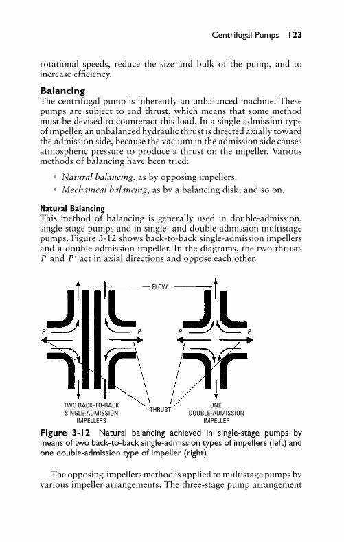
P1: FCH
GB098-03 GB098-Miller September 13, 2004 17:50 Char Count= 0
Centrifugal Pumps 123
rotational speeds, reduce the size and bulk of the pump, and toincrease efficiency.
BalancingThe centrifugal pump is inherently an unbalanced machine. Thesepumps are subject to end thrust, which means that some methodmust be devised to counteract this load. In a single-admission typeof impeller, an unbalanced hydraulic thrust is directed axially towardthe admission side, because the vacuum in the admission side causesatmospheric pressure to produce a thrust on the impeller. Variousmethods of balancing have been tried:
� Natural balancing, as by opposing impellers.� Mechanical balancing, as by a balancing disk, and so on.
Natural BalancingThis method of balancing is generally used in double-admission,single-stage pumps and in single- and double-admission multistagepumps. Figure 3-12 shows back-to-back single-admission impellersand a double-admission impeller. In the diagrams, the two thrustsP and P ′ act in axial directions and oppose each other.
FLOW
THRUSTTWO BACK-TO-BACKSINGLE-ADMISSION
IMPELLERS
ONE DOUBLE-ADMISSION
IMPELLER
P' P P' P
Figure 3-12 Natural balancing achieved in single-stage pumps bymeans of two back-to-back single-admission types of impellers (left) andone double-admission type of impeller (right).
The opposing-impellers method is applied to multistage pumps byvarious impeller arrangements. The three-stage pump arrangement
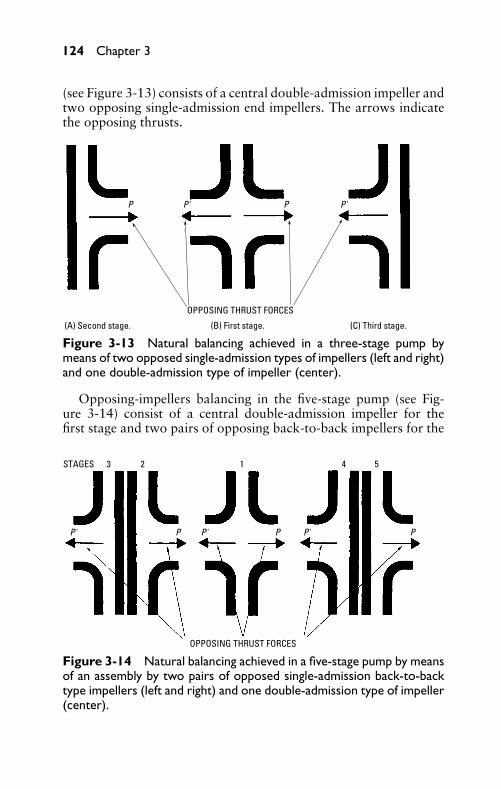
P1: FCH
GB098-03 GB098-Miller September 13, 2004 17:50 Char Count= 0
124 Chapter 3
(see Figure 3-13) consists of a central double-admission impeller andtwo opposing single-admission end impellers. The arrows indicatethe opposing thrusts.
(A) Second stage. (B) First stage. (C) Third stage.
OPPOSING THRUST FORCES
P' P P'P
Figure 3-13 Natural balancing achieved in a three-stage pump bymeans of two opposed single-admission types of impellers (left and right)and one double-admission type of impeller (center).
Opposing-impellers balancing in the five-stage pump (see Fig-ure 3-14) consist of a central double-admission impeller for thefirst stage and two pairs of opposing back-to-back impellers for the
OPPOSING THRUST FORCES
STAGES 3 2 1 4 5
P' P P' P P' P
Figure 3-14 Natural balancing achieved in a five-stage pump by meansof an assembly by two pairs of opposed single-admission back-to-backtype impellers (left and right) and one double-admission type of impeller(center).
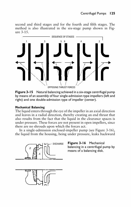
P1: FCH
GB098-03 GB098-Miller September 13, 2004 17:50 Char Count= 0
Centrifugal Pumps 125
second and third stages and for the fourth and fifth stages. Themethod is also illustrated in the six-stage pump shown in Fig-ure 3-15.
OPPOSING THRUST FORCES
3 21 45 6
SEQUENCE OF STAGES
Figure 3-15 Natural balancing achieved in a six-stage centrifugal pumpby means of an assembly of four single-admission type impellers (left andright) and one double-admission type of impeller (center).
Mechanical BalancingThe liquid enters through the eye of the impeller in an axial directionand leaves in a radial direction, thereby creating an end thrust thatalso results from the fact that the liquid in the clearance spaces isunder pressure. These forces are not present in open impellers, sincethere are no shrouds upon which the forces act.
In a single-admission enclosed-impeller pump (see Figure 3-16),the liquid from the housing, being under pressure, leaks backward
DISCHARGE
A
D
C
B
Figure 3-16 Mechanicalbalancing in a centrifugal pump bymeans of a balancing disk.
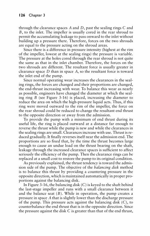
P1: FCH
GB098-03 GB098-Miller September 13, 2004 17:50 Char Count= 0
126 Chapter 3
through the clearance spaces A and D, past the sealing rings C andB, to the inlet. The impeller is usually cored in the rear shroud topermit the accumulating leakage to pass onward to the inlet withoutbuilding up a pressure there. Therefore, forces on the two shroudsare equal to the pressure acting on the shroud areas.
Since there is a difference in pressure intensity (highest at the rimof the impeller, lowest at the sealing rings) the pressure is variable.The pressure at the holes cored through the rear shroud is not quitethe same as that in the inlet chamber. Therefore, the forces on thetwo shrouds are different. The resultant force is usually greater inclearance space D than in space A, so the resultant force is towardthe inlet end of the pump.
Since normal operating wear increases the clearances in the seal-ing rings, the forces are changed and their proportions are changed,the end-thrust increasing with wear. To balance this wear as nearlyas possible, engineers have changed the diameter at which the seal-ing ring B (see Figure 3-16) is placed, increasing the diameter toreduce the area on which the high-pressure liquid acts. Thus, if thisring were moved outward to the rim of the impeller, the force onthe rear shroud could be reduced to change the resultant end thrustto the opposite direction or away from the admission.
To provide the pump with a minimum of end thrust during itsuseful life, the ring is placed outward at a distance far enough toreverse the thrust while the pump is new and while the clearances inthe sealing rings are small. Clearances increase with use. Thrust is re-duced gradually. It finally reverses itself near the admission end. Theproportions are so fixed that, by the time the thrust becomes largeenough to cause an undue load on the thrust bearing on the shaft,leakage through the increased clearance spaces is sufficient to affectseriously the efficiency of the pump. Then the clearance rings can bereplaced at a small cost to restore the pump to its original condition.
As previously explained, the thrust tendency is toward the admis-sion side of the pump. The objective of the balancing disk methodis to balance this thrust by providing a countering pressure in theopposite direction, which is maintained automatically in proper pro-portions against the balancing disk.
In Figure 3-16, the balancing disk (C) is keyed to the shaft behindthe last-stage impeller and runs with a small clearance between itand the balance seat (B). While in operation, the pump creates apressure in space A that is slightly lower than the discharge pressureof the pump. This pressure acts against the balancing disk (C), tocounterbalance the end thrust that is in the opposite direction. Sincethe pressure against the disk C is greater than that of the end thrust,
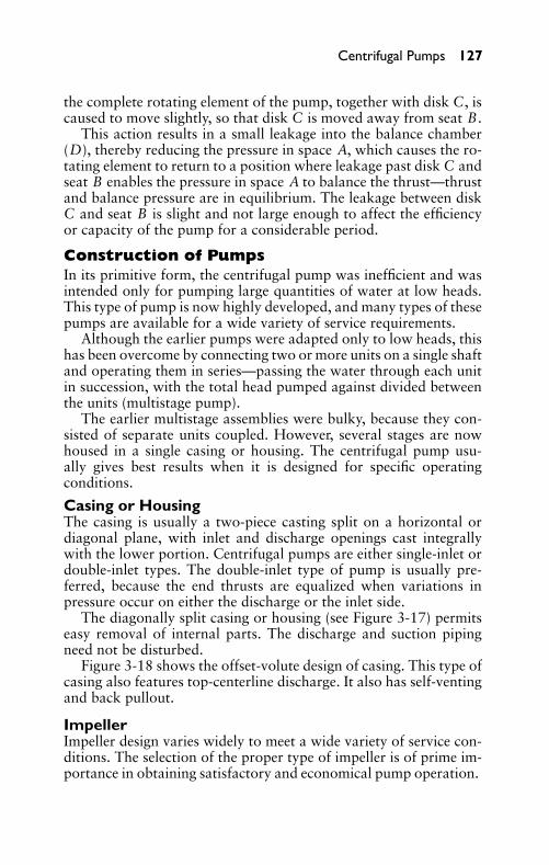
P1: FCH
GB098-03 GB098-Miller September 13, 2004 17:50 Char Count= 0
Centrifugal Pumps 127
the complete rotating element of the pump, together with disk C, iscaused to move slightly, so that disk C is moved away from seat B.
This action results in a small leakage into the balance chamber(D), thereby reducing the pressure in space A, which causes the ro-tating element to return to a position where leakage past disk C andseat B enables the pressure in space A to balance the thrust—thrustand balance pressure are in equilibrium. The leakage between diskC and seat B is slight and not large enough to affect the efficiencyor capacity of the pump for a considerable period.
Construction of PumpsIn its primitive form, the centrifugal pump was inefficient and wasintended only for pumping large quantities of water at low heads.This type of pump is now highly developed, and many types of thesepumps are available for a wide variety of service requirements.
Although the earlier pumps were adapted only to low heads, thishas been overcome by connecting two or more units on a single shaftand operating them in series—passing the water through each unitin succession, with the total head pumped against divided betweenthe units (multistage pump).
The earlier multistage assemblies were bulky, because they con-sisted of separate units coupled. However, several stages are nowhoused in a single casing or housing. The centrifugal pump usu-ally gives best results when it is designed for specific operatingconditions.
Casing or HousingThe casing is usually a two-piece casting split on a horizontal ordiagonal plane, with inlet and discharge openings cast integrallywith the lower portion. Centrifugal pumps are either single-inlet ordouble-inlet types. The double-inlet type of pump is usually pre-ferred, because the end thrusts are equalized when variations inpressure occur on either the discharge or the inlet side.
The diagonally split casing or housing (see Figure 3-17) permitseasy removal of internal parts. The discharge and suction pipingneed not be disturbed.
Figure 3-18 shows the offset-volute design of casing. This type ofcasing also features top-centerline discharge. It also has self-ventingand back pullout.
ImpellerImpeller design varies widely to meet a wide variety of service con-ditions. The selection of the proper type of impeller is of prime im-portance in obtaining satisfactory and economical pump operation.
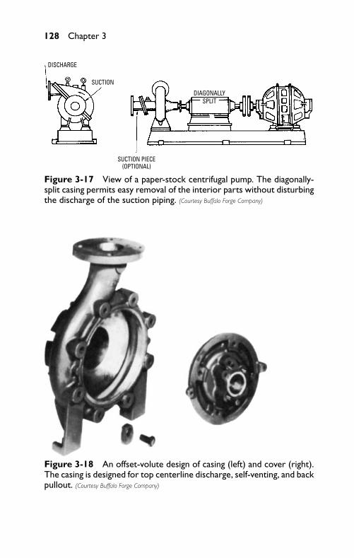
P1: FCH
GB098-03 GB098-Miller September 13, 2004 17:50 Char Count= 0
128 Chapter 3
DISCHARGE
SUCTION
SUCTION PIECE(OPTIONAL)
DIAGONALLYSPLIT
Figure 3-17 View of a paper-stock centrifugal pump. The diagonally-split casing permits easy removal of the interior parts without disturbingthe discharge of the suction piping. (Courtesy Buffalo Forge Company)
Figure 3-18 An offset-volute design of casing (left) and cover (right).The casing is designed for top centerline discharge, self-venting, and backpullout. (Courtesy Buffalo Forge Company)
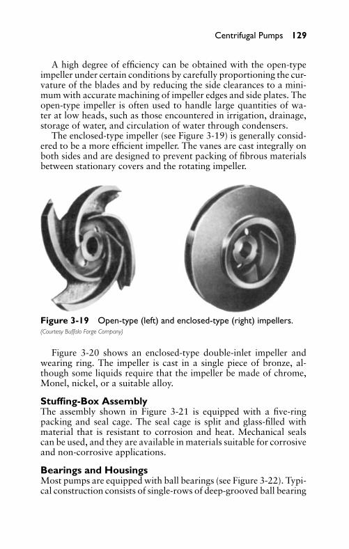
P1: FCH
GB098-03 GB098-Miller September 13, 2004 17:50 Char Count= 0
Centrifugal Pumps 129
A high degree of efficiency can be obtained with the open-typeimpeller under certain conditions by carefully proportioning the cur-vature of the blades and by reducing the side clearances to a mini-mum with accurate machining of impeller edges and side plates. Theopen-type impeller is often used to handle large quantities of wa-ter at low heads, such as those encountered in irrigation, drainage,storage of water, and circulation of water through condensers.
The enclosed-type impeller (see Figure 3-19) is generally consid-ered to be a more efficient impeller. The vanes are cast integrally onboth sides and are designed to prevent packing of fibrous materialsbetween stationary covers and the rotating impeller.
Figure 3-19 Open-type (left) and enclosed-type (right) impellers.(Courtesy Buffalo Forge Company)
Figure 3-20 shows an enclosed-type double-inlet impeller andwearing ring. The impeller is cast in a single piece of bronze, al-though some liquids require that the impeller be made of chrome,Monel, nickel, or a suitable alloy.
Stuffing-Box AssemblyThe assembly shown in Figure 3-21 is equipped with a five-ringpacking and seal cage. The seal cage is split and glass-filled withmaterial that is resistant to corrosion and heat. Mechanical sealscan be used, and they are available in materials suitable for corrosiveand non-corrosive applications.
Bearings and HousingsMost pumps are equipped with ball bearings (see Figure 3-22). Typi-cal construction consists of single-rows of deep-grooved ball bearing
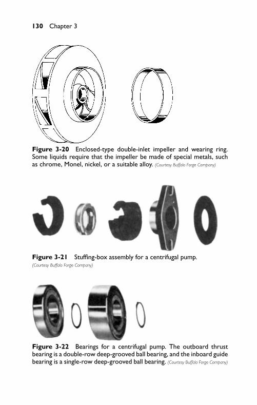
P1: FCH
GB098-03 GB098-Miller September 13, 2004 17:50 Char Count= 0
130 Chapter 3
Figure 3-20 Enclosed-type double-inlet impeller and wearing ring.Some liquids require that the impeller be made of special metals, suchas chrome, Monel, nickel, or a suitable alloy. (Courtesy Buffalo Forge Company)
Figure 3-21 Stuffing-box assembly for a centrifugal pump.(Courtesy Buffalo Forge Company)
Figure 3-22 Bearings for a centrifugal pump. The outboard thrustbearing is a double-row deep-grooved ball bearing, and the inboard guidebearing is a single-row deep-grooved ball bearing. (Courtesy Buffalo Forge Company)
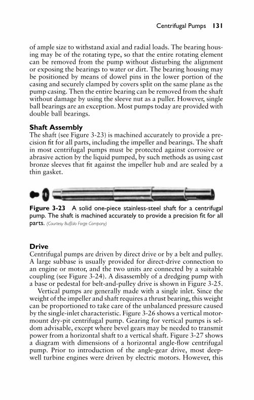
P1: FCH
GB098-03 GB098-Miller September 13, 2004 17:50 Char Count= 0
Centrifugal Pumps 131
of ample size to withstand axial and radial loads. The bearing hous-ing may be of the rotating type, so that the entire rotating elementcan be removed from the pump without disturbing the alignmentor exposing the bearings to water or dirt. The bearing housing maybe positioned by means of dowel pins in the lower portion of thecasing and securely clamped by covers split on the same plane as thepump casing. Then the entire bearing can be removed from the shaftwithout damage by using the sleeve nut as a puller. However, singleball bearings are an exception. Most pumps today are provided withdouble ball bearings.
Shaft AssemblyThe shaft (see Figure 3-23) is machined accurately to provide a pre-cision fit for all parts, including the impeller and bearings. The shaftin most centrifugal pumps must be protected against corrosive orabrasive action by the liquid pumped, by such methods as using castbronze sleeves that fit against the impeller hub and are sealed by athin gasket.
Figure 3-23 A solid one-piece stainless-steel shaft for a centrifugalpump. The shaft is machined accurately to provide a precision fit for allparts. (Courtesy Buffalo Forge Company)
DriveCentrifugal pumps are driven by direct drive or by a belt and pulley.A large subbase is usually provided for direct-drive connection toan engine or motor, and the two units are connected by a suitablecoupling (see Figure 3-24). A disassembly of a dredging pump witha base or pedestal for belt-and-pulley drive is shown in Figure 3-25.
Vertical pumps are generally made with a single inlet. Since theweight of the impeller and shaft requires a thrust bearing, this weightcan be proportioned to take care of the unbalanced pressure causedby the single-inlet characteristic. Figure 3-26 shows a vertical motor-mount dry-pit centrifugal pump. Gearing for vertical pumps is sel-dom advisable, except where bevel gears may be needed to transmitpower from a horizontal shaft to a vertical shaft. Figure 3-27 showsa diagram with dimensions of a horizontal angle-flow centrifugalpump. Prior to introduction of the angle-gear drive, most deep-well turbine engines were driven by electric motors. However, this
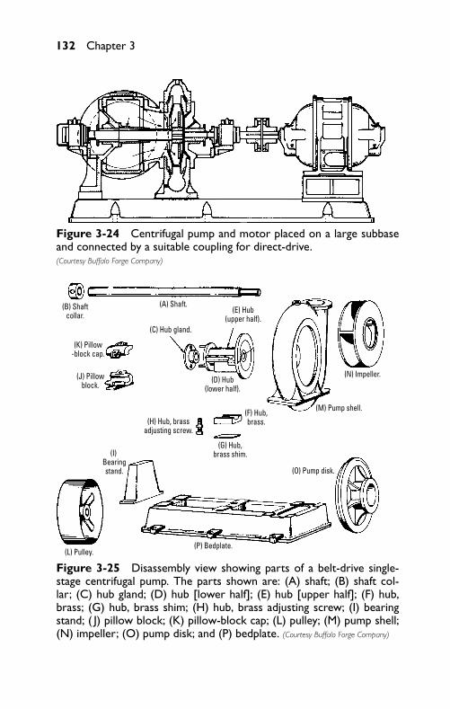
P1: FCH
GB098-03 GB098-Miller September 13, 2004 17:50 Char Count= 0
132 Chapter 3
Figure 3-24 Centrifugal pump and motor placed on a large subbaseand connected by a suitable coupling for direct-drive.(Courtesy Buffalo Forge Company)
(A) Shaft.(B) Shaftcollar.
(K) Pillow-block cap.
(C) Hub gland.
(D) Hub(lower half).
(F) Hub,brass.
(G) Hub,brass shim.(I)
Bearingstand.
(L) Pulley.(P) Bedplate.
(O) Pump disk.
(M) Pump shell.
(N) Impeller.
(H) Hub, brassadjusting screw.
(E) Hub(upper half).
(J) Pillowblock.
Figure 3-25 Disassembly view showing parts of a belt-drive single-stage centrifugal pump. The parts shown are: (A) shaft; (B) shaft col-lar; (C) hub gland; (D) hub [lower half]; (E) hub [upper half]; (F) hub,brass; (G) hub, brass shim; (H) hub, brass adjusting screw; (I) bearingstand; ( J) pillow block; (K) pillow-block cap; (L) pulley; (M) pump shell;(N) impeller; (O) pump disk; and (P) bedplate. (Courtesy Buffalo Forge Company)
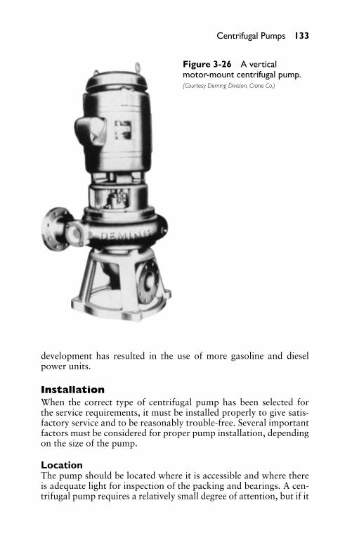
P1: FCH
GB098-03 GB098-Miller September 13, 2004 17:50 Char Count= 0
Centrifugal Pumps 133
Figure 3-26 A verticalmotor-mount centrifugal pump.(Courtesy Deming Division, Crane Co.)
development has resulted in the use of more gasoline and dieselpower units.
InstallationWhen the correct type of centrifugal pump has been selected forthe service requirements, it must be installed properly to give satis-factory service and to be reasonably trouble-free. Several importantfactors must be considered for proper pump installation, dependingon the size of the pump.
LocationThe pump should be located where it is accessible and where thereis adequate light for inspection of the packing and bearings. A cen-trifugal pump requires a relatively small degree of attention, but if it
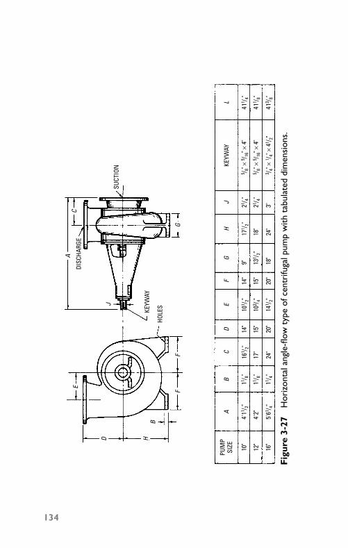
P1: FCH
GB098-03 GB098-Miller September 13, 2004 17:50 Char Count= 0
PUM
PSI
ZEA
BC
DE
FG
HJ
LKE
YWAY
10"
411 / 4"
411 / 8"
413 / 8"
4'11 / 2"
4'2"
5'61 / 4"
12"
16"
101 / 2"
141 / 2"
103 / 4"
14"
15"
20"
14"
15"
20"
131 / 2"
9" 18"
161 / 2"
17"
24"
171 / 2"
18"
24"
11 / 8"
11 / 8"
11 / 4"3"21 / 4"
21 / 4"
5 / 8" ×
5 / 16" ×
4"
5 / 8" ×
5 / 16" ×
4"
3 / 4" ×
1 / 4" ×
41 / 2"
E
D HB
FF
J
AC
G
HOLE
S
KEYW
AY
DISC
HARG
E
SUCT
ION
Fig
ure
3-27
Hor
izon
tala
ngle
-flow
type
ofce
ntri
fuga
lpum
pw
ithta
bula
ted
dim
ensi
ons.
134
P1: FCH
GB098-03 GB098-Miller September 13, 2004 17:50 Char Count= 0
Centrifugal Pumps 135
is inaccessible, it probably receives no attention until a breakdownrequiring major repairs occurs.
The height of lift must also be considered. The lift is affected bytemperature, height above sea level, and pipe friction, foot valve,and strainer losses. The elevation of the pump with respect to theliquid to be pumped should be at a height that is within the practicallimit of the dynamic lift.
Piping also affects the location of the pump. The pump shouldbe located so that the piping layout is as simple as possible.
FoundationThe foundation should be rugged enough to afford a permanent rigidsupport to the entire base area of the bedplate and to absorb normalstrains and shocks that may be encountered in service. Concretefoundations are usually the most satisfactory.
Foundation bolts of the specified size should be located in theconcrete according to drawings submitted prior to shipment of theunit. If the unit is mounted on steelwork or other type of structure,it should (if possible) be placed directly above the main members,beams, and walls, and it should be supported in such a way thatthe base plate cannot be distorted or the alignment disturbed by ayielding or springing action of the structure or the base plate. Thebottom portion of the bedplate should be located approximately3/4 inch above the top of the foundation to leave space for grouting.
LevelingPumps are usually shipped already mounted, and it is usually un-necessary to remove either the pump or the driving unit from thebase plate for leveling. The unit should be placed above the founda-tion and supported by short strips of steel plate and wedges near thefoundation bolts. A 3/4-inch to 2-inch space between the base plateand the foundation should be allowed for grouting. The couplingbolts should be removed before proceeding with leveling the unitand aligning the coupling halves.
When scraped clean, the projecting edges of the pads supportingthe pump and motor feet can be used for leveling, employing a spiritlevel. If possible, the level should be placed on an exposed part ofthe pump shaft, sleeve, or planed surface of the casing.
The wedges underneath the base plate can be adjusted until thepump shaft is level, and the flanges of the suction and dischargenozzles are either vertical or horizontal, as required. At the sametime, the pump should be placed at the specified height and location.Accurate alignment of the unbolted coupling halves between the
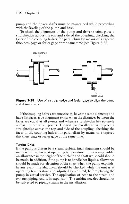
P1: FCH
GB098-03 GB098-Miller September 13, 2004 17:50 Char Count= 0
136 Chapter 3
pump and the driver shafts must be maintained while proceedingwith the leveling of the pump and base.
To check the alignment of the pump and driver shafts, place astraightedge across the top and side of the coupling, checking thefaces of the coupling halves for parallelism by means of a taperedthickness gage or feeler gage at the same time (see Figure 3-28).
STRAIGHTEDGE
FEELER GAGE
Figure 3-28 Use of a straightedge and feeler gage to align the pumpand driver shafts.
If the coupling halves are true circles, have the same diameter, andhave flat faces, true alignment exists when the distances between thefaces are equal at all points and when a straightedge lies squarelyacross the rim at all points. The test for parallelism is to place astraightedge across the top and side of the coupling, checking thefaces of the coupling halves for parallelism by means of a taperedthickness gage or feeler gage at the same time.
Turbine DriveIf the pump is driven by a steam turbine, final alignment should bemade with the driver at operating temperature. If this is impossible,an allowance in the height of the turbine and shaft while cold shouldbe made. In addition, if the pump is to handle hot liquids, allowanceshould be made for elevation of the shaft when the pump expands.In any event, the alignment should be checked while the unit is atoperating temperature and adjusted as required, before placing thepump in actual service. The application of heat to the steam andexhaust piping results in expansion. The turbine nozzles should notbe subjected to piping strains in the installation.
P1: FCH
GB098-03 GB098-Miller September 13, 2004 17:50 Char Count= 0
Centrifugal Pumps 137
Motor DriveAn allowance for heat is unnecessary for electric motors. The motoralone should be operated (if possible) before aligning the pump, sothat the magnetic center of the rotor can be determined. If this is im-possible, the rotor of the motor should be turned over and reversedto determine collar clearances, and then placed in the middle posi-tion for aligning. If the faces are not parallel, the thickness gage (orfeelers) varies at different points. If one coupling is higher than theother, the distance can be determined by means of the straightedgeand feeler gages.
Space between Coupling FacesThe clearance between the faces of the couplings of the pin-and-buffer type, and the ends of the shafts in other types of couplings,should be set so that they cannot touch, rub, or exert a force on eitherthe pump or the driver. The amount of clearance may vary with thesize and type of coupling used. Sufficient clearance for the unham-pered endwise movement of the shaft of the driving element to thelimit of its bearing clearance should be allowed. On motor-drivenunits, the magnetic center of the motor determines the running po-sition of the half-coupling of the motor. This can be checked byoperating the motor while it is disconnected.
GroutingThe grouting process involves pouring a mixture of cement, sand,and water into the voids of the stone, brick, or concrete work, eitherto provide a solid bearing or to fasten anchor bolts, dowels, and soon. The usual grouting mixture consists of one part cement, twoparts sand, and enough water to cause the mixture to flow freelyunderneath the bedplate.
A wooden form is built around the outside of the bedplate tocontain the grout and to provide sufficient head for ensuring a flowof the mixture beneath the entire head plate. The grout should beallowed to set for 48 hours. Then the hold-down bolts should betightened and the coupling halves rechecked.
Inlet PipingIn a new installation, it is advisable to flush the inlet pipe with clearwater before connecting it to the pump. Except for misalignment,most problems with individual centrifugal pump installations can betraced to faults in the inlet lines. It is extremely important to installthe inlet piping correctly.
The diameter of the inlet piping should not be smaller than theinlet opening, and it should be as short and direct as possible. If
P1: FCH
GB098-03 GB098-Miller September 13, 2004 17:50 Char Count= 0
138 Chapter 3
a long inlet cannot be avoided, the size of the piping should beincreased. Air pockets and high spots in an inlet line invariably causetrouble. Preferably, there should be a continual rise (without highspots) from the source of supply to the pump.
When the supply liquid is at its lowest level, the end of the pipeshould be submerged to a depth equal to four times its diameter(for large pipes). Smaller pipes should be submerged to a depth of2 to 3 feet. After installation is completed, the inlet piping should beblanked off and tested hydrostatically for air leaks before the pumpis operated.
A strainer should be attached to the end of the inlet pipe to pre-vent lodging of foreign material in the impellers. The clear and freeopening of the strainer should be equal to three or four times thearea of the inlet pipe. If the strainer is likely to become clogged fre-quently, the inlet pipe should be placed where it is accessible. A footvalve for convenience in priming may be necessary where the pumpis subjected to intermittent service. The size and type of foot valveshould be selected carefully to avoid friction loss through the valve.
Discharge PipingThe discharge piping (like the inlet piping) should also be as shortand as free of elbows as possible, to reduce friction. Check valvesand gate valves should be placed near the pump. The check valveprotects the casing of the pump from breakage caused by waterhammer, and it prevents the pump operating in reverse if the drivershould fail. The gate valve can be used to shut off the pump fromthe discharge piping when inspection or repair is necessary.
Pumps Handling High-Temperature LiquidsSpecial types of multistage pumps are constructed for handling high-temperature liquids, with a key and keyway on the feet and base ofthe lower half of the casing. One end of the pump is bolted securely,but the other end (on some units) is bolted with spring washerspositioned underneath the nuts on the casing feet, permitting one endof the casing to move laterally as the casing expands. Some specialtypes of hot-liquid multistage pumps are doweled at the inboard end,and other types are doweled at the thrust-bearing end, sometimeswith the dowels placed crosswise. Dowels at the opposite end (ifused) are fitted parallel to the pump shaft, to allow the casing toexpand at high temperatures.
When handling hot liquids, the nozzle flanges should be discon-nected after the unit has been placed in service, to determine whetherthe expansion is in the proper direction.
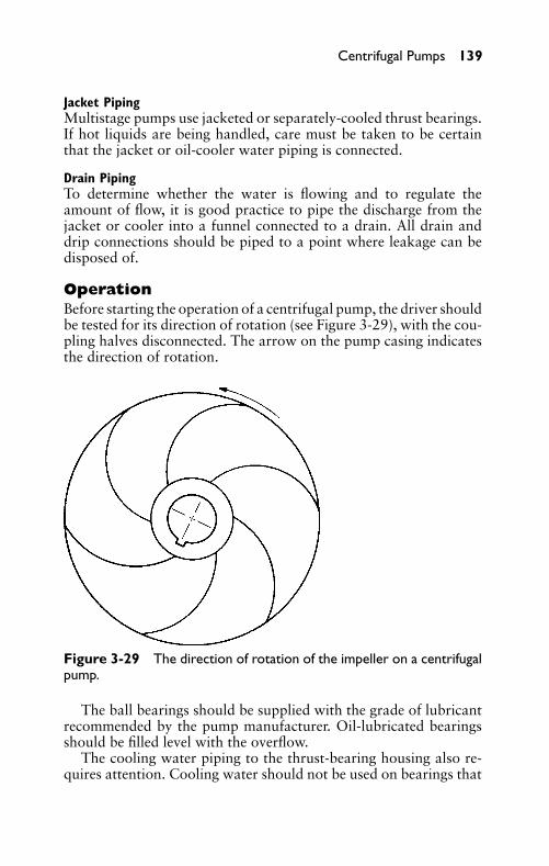
P1: FCH
GB098-03 GB098-Miller September 13, 2004 17:50 Char Count= 0
Centrifugal Pumps 139
Jacket PipingMultistage pumps use jacketed or separately-cooled thrust bearings.If hot liquids are being handled, care must be taken to be certainthat the jacket or oil-cooler water piping is connected.
Drain PipingTo determine whether the water is flowing and to regulate theamount of flow, it is good practice to pipe the discharge from thejacket or cooler into a funnel connected to a drain. All drain anddrip connections should be piped to a point where leakage can bedisposed of.
OperationBefore starting the operation of a centrifugal pump, the driver shouldbe tested for its direction of rotation (see Figure 3-29), with the cou-pling halves disconnected. The arrow on the pump casing indicatesthe direction of rotation.
Figure 3-29 The direction of rotation of the impeller on a centrifugalpump.
The ball bearings should be supplied with the grade of lubricantrecommended by the pump manufacturer. Oil-lubricated bearingsshould be filled level with the overflow.
The cooling water piping to the thrust-bearing housing also re-quires attention. Cooling water should not be used on bearings that
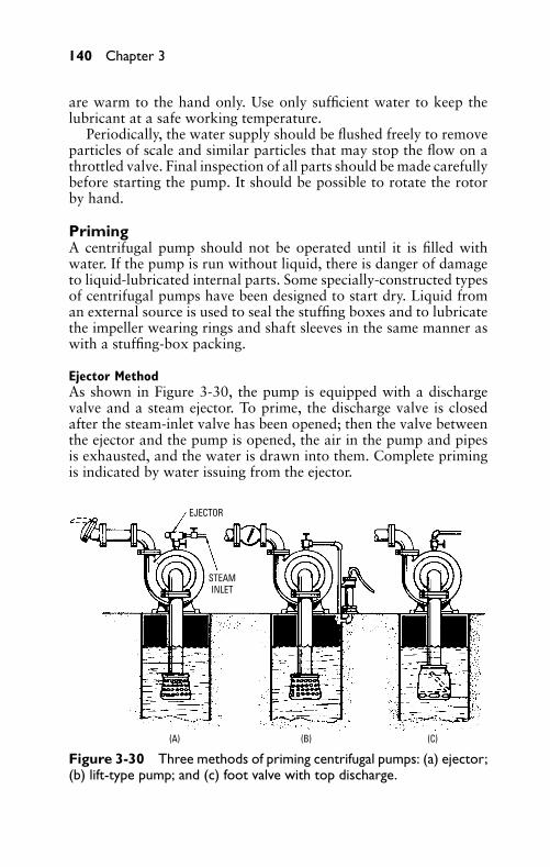
P1: FCH
GB098-03 GB098-Miller September 13, 2004 17:50 Char Count= 0
140 Chapter 3
are warm to the hand only. Use only sufficient water to keep thelubricant at a safe working temperature.
Periodically, the water supply should be flushed freely to removeparticles of scale and similar particles that may stop the flow on athrottled valve. Final inspection of all parts should be made carefullybefore starting the pump. It should be possible to rotate the rotorby hand.
PrimingA centrifugal pump should not be operated until it is filled withwater. If the pump is run without liquid, there is danger of damageto liquid-lubricated internal parts. Some specially-constructed typesof centrifugal pumps have been designed to start dry. Liquid froman external source is used to seal the stuffing boxes and to lubricatethe impeller wearing rings and shaft sleeves in the same manner aswith a stuffing-box packing.
Ejector MethodAs shown in Figure 3-30, the pump is equipped with a dischargevalve and a steam ejector. To prime, the discharge valve is closedafter the steam-inlet valve has been opened; then the valve betweenthe ejector and the pump is opened, the air in the pump and pipesis exhausted, and the water is drawn into them. Complete primingis indicated by water issuing from the ejector.
EJECTOR
STEAMINLET
(A) (B) (C)
Figure 3-30 Three methods of priming centrifugal pumps: (a) ejector;(b) lift-type pump; and (c) foot valve with top discharge.
P1: FCH
GB098-03 GB098-Miller September 13, 2004 17:50 Char Count= 0
Centrifugal Pumps 141
The ejector is shut off by first closing the valve between the ejec-tor and the pump, and then closing the steam-inlet valve. If it isinconvenient to place the ejector near the pump, the air pipe canbe extended, using an air pipe that is slightly larger than when theejector is placed near the pump.
Hand-Type Lift Pump (or Powered Air Pump) MethodA check valve can be used instead of the discharge valve, and eithera hand-type old-fashioned lift pump (see Figure 3-30) or a poweredair pump can be substituted for the steam ejector. A valve should beplaced in the air pipe. The valve should be closed before starting. Inthe older installations, the kitchen-type lift pumps were often usedfor priming. Sometimes the kitchen-type pumps themselves require asmall quantity of water to water-seal them, making them an effectiveair pump.
Foot-Valve and Top-Discharge MethodWhen the foot valve is used (see Figure 3-30), the centrifugal pumpand inlet pipe are filled with water through the discharge or topportion of the pump from either a small tank or a hand-type pump.If the inlet pipe is long, at least 5 feet of discharge head on the pumpis required to prevent water from being thrown out before the waterin the inlet line has begun to move, causing failure in starting. Whencheck or discharge valves are used, a vacuum gage placed on the air-priming pump at the head of the well or pit indicates that the pumpis primed. A steam-type air ejector may be operated with water if30 to 40 pounds of water pressure is available. However, a specialtype of ejector is required.
For automatic priming, a pressure regulator can be connectedinto the discharge line. The regulator automatically starts an airpump if the main pump loses its prime. It stops the priming pumpwhen the priming action is completed.
In the float-controlled automatic priming system (see Fig-ure 3-31), a priming valve is connected between the top of the cas-ing of the pump and a float-controlled air valve. The air valve isconnected to a priming switch, with the contacts in series with thecontrol circuit of the main motor starter. A check valve in the dis-charge line operates a switch that shunts the priming switch.
In actual operation, the priming valve and air valve are in theindicated positions so long as the pump is not primed. When the floatswitch closes, the priming pump is started. It continues in operationuntil the main pump is primed and until the water is high enoughin the float chamber to close the priming switch. The closing ofthe priming switch starts the main pump, and the priming pump is
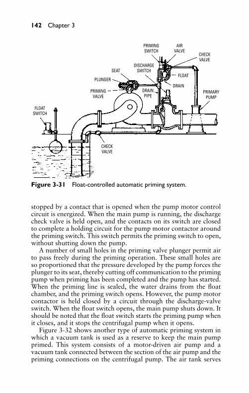
P1: FCH
GB098-03 GB098-Miller September 13, 2004 17:50 Char Count= 0
142 Chapter 3
FLOATSWITCH
PRIMINGVALVE
CHECKVALVE
PRIMINGSWITCH
PLUNGER
SEATDISCHARGE
SWITCH
AIRVALVE
CHECKVALVE
FLOAT
DRAINDRAINPIPE
PRIMARYPUMP
Figure 3-31 Float-controlled automatic priming system.
stopped by a contact that is opened when the pump motor controlcircuit is energized. When the main pump is running, the dischargecheck valve is held open, and the contacts on its switch are closedto complete a holding circuit for the pump motor contactor aroundthe priming switch. This switch permits the priming switch to open,without shutting down the pump.
A number of small holes in the priming valve plunger permit airto pass freely during the priming operation. These small holes areso proportioned that the pressure developed by the pump forces theplunger to its seat, thereby cutting off communication to the primingpump when priming has been completed and the pump has started.When the priming line is sealed, the water drains from the floatchamber, and the priming switch opens. However, the pump motorcontactor is held closed by a circuit through the discharge-valveswitch. When the float switch opens, the main pump shuts down. Itshould be noted that the float switch starts the priming pump whenit closes, and it stops the centrifugal pump when it opens.
Figure 3-32 shows another type of automatic priming system inwhich a vacuum tank is used as a reserve to keep the main pumpprimed. This system consists of a motor-driven air pump and avacuum tank connected between the section of the air pump and thepriming connections on the centrifugal pump. The air tank serves
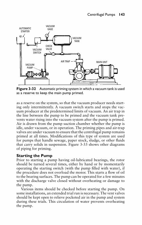
P1: FCH
GB098-03 GB098-Miller September 13, 2004 17:50 Char Count= 0
Centrifugal Pumps 143
AUTOMATICSTARTER
VACUUMGAGE
VACUUMSWITCH
VACUUMPUMP
VACUUMTANK
AIR TRAP MAIN UNIT
CHECKVALVE
Figure 3-32 Automatic priming system in which a vacuum tank is usedas a reserve to keep the main pump primed.
as a reserve on the system, so that the vacuum producer needs start-ing only intermittently. A vacuum switch starts and stops the vac-uum producer at the predetermined limits of vacuum. An air trap inthe line between the pump to be primed and the vacuum tank pre-vents water rising into the vacuum system after the pump is primed.Air is drawn from the pump suction chamber whether the pump isidle, under vacuum, or in operation. The priming pipes and air-trapvalves are under vacuum to ensure that the centrifugal pump remainsprimed at all times. Modifications of this type of system are usedfor pumps that handle sewage, paper stock, sludge, or other fluidsthat carry solids in suspension. Figure 3-33 shows other diagramsof piping for priming.
Starting the PumpPrior to starting a pump having oil-lubricated bearings, the rotorshould be turned several times, either by hand or by momentarilyoperating the starting switch (with the pump filled with water), ifthe procedure does not overload the motor. This starts a flow of oilto the bearing surfaces. The pump can be operated for a few minuteswith the discharge valve closed without overheating or damage tothe pump.
Various items should be checked before starting the pump. Onsome installations, an extended trial run is necessary. The vent valvesshould be kept open to relieve pocketed air in the pump and systemduring these trials. This circulation of water prevents overheatingthe pump.
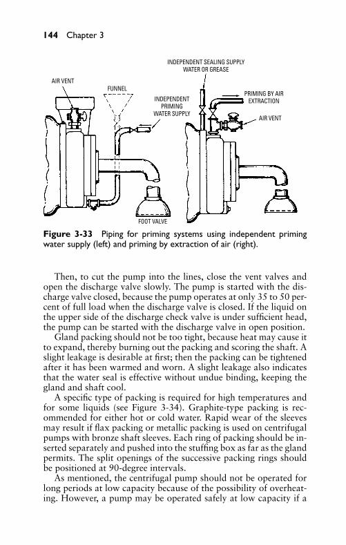
P1: FCH
GB098-03 GB098-Miller September 13, 2004 17:50 Char Count= 0
144 Chapter 3
AIR VENTFUNNEL
INDEPENDENTPRIMING
WATER SUPPLY
INDEPENDENT SEALING SUPPLYWATER OR GREASE
PRIMING BY AIREXTRACTION
AIR VENT
FOOT VALVE
Figure 3-33 Piping for priming systems using independent primingwater supply (left) and priming by extraction of air (right).
Then, to cut the pump into the lines, close the vent valves andopen the discharge valve slowly. The pump is started with the dis-charge valve closed, because the pump operates at only 35 to 50 per-cent of full load when the discharge valve is closed. If the liquid onthe upper side of the discharge check valve is under sufficient head,the pump can be started with the discharge valve in open position.
Gland packing should not be too tight, because heat may cause itto expand, thereby burning out the packing and scoring the shaft. Aslight leakage is desirable at first; then the packing can be tightenedafter it has been warmed and worn. A slight leakage also indicatesthat the water seal is effective without undue binding, keeping thegland and shaft cool.
A specific type of packing is required for high temperatures andfor some liquids (see Figure 3-34). Graphite-type packing is rec-ommended for either hot or cold water. Rapid wear of the sleevesmay result if flax packing or metallic packing is used on centrifugalpumps with bronze shaft sleeves. Each ring of packing should be in-serted separately and pushed into the stuffing box as far as the glandpermits. The split openings of the successive packing rings shouldbe positioned at 90-degree intervals.
As mentioned, the centrifugal pump should not be operated forlong periods at low capacity because of the possibility of overheat-ing. However, a pump may be operated safely at low capacity if a
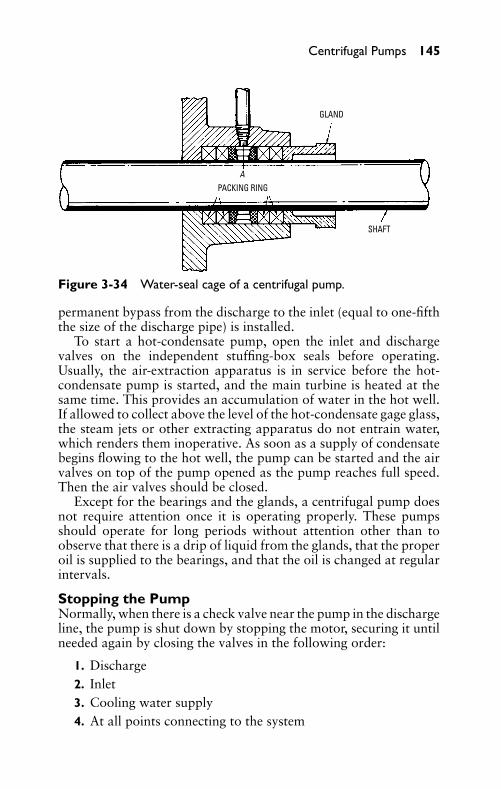
P1: FCH
GB098-03 GB098-Miller September 13, 2004 17:50 Char Count= 0
Centrifugal Pumps 145
PACKING RINGA
GLAND
SHAFT
Figure 3-34 Water-seal cage of a centrifugal pump.
permanent bypass from the discharge to the inlet (equal to one-fifththe size of the discharge pipe) is installed.
To start a hot-condensate pump, open the inlet and dischargevalves on the independent stuffing-box seals before operating.Usually, the air-extraction apparatus is in service before the hot-condensate pump is started, and the main turbine is heated at thesame time. This provides an accumulation of water in the hot well.If allowed to collect above the level of the hot-condensate gage glass,the steam jets or other extracting apparatus do not entrain water,which renders them inoperative. As soon as a supply of condensatebegins flowing to the hot well, the pump can be started and the airvalves on top of the pump opened as the pump reaches full speed.Then the air valves should be closed.
Except for the bearings and the glands, a centrifugal pump doesnot require attention once it is operating properly. These pumpsshould operate for long periods without attention other than toobserve that there is a drip of liquid from the glands, that the properoil is supplied to the bearings, and that the oil is changed at regularintervals.
Stopping the PumpNormally, when there is a check valve near the pump in the dischargeline, the pump is shut down by stopping the motor, securing it untilneeded again by closing the valves in the following order:
1. Discharge2. Inlet3. Cooling water supply4. At all points connecting to the system
P1: FCH
GB098-03 GB098-Miller September 13, 2004 17:50 Char Count= 0
146 Chapter 3
Usually, when the pump is stopped in this manner, the dischargegate valve need not be opened. However, in some installations,surges in the piping may impose heavy shocks on both the lines andthe pump when the flow of water under high pressure is arrested.Then it is good practice to first close the discharge gate valve, toeliminate shock.
If a pump remains idle for some time after it is stopped, it grad-ually loses priming, because the liquid drains through the glands.If it is necessary to keep the pump primed for emergency use, thisshould be kept in mind when the pump is stopped. It is not necessaryto close the inlet and discharge valves, because the glands may leakbecause of sustained pressure on a stationary shaft. The gland nutsshould not be tightened unless preparation is made to loosen themagain when starting the pump.
Abnormal Operating ConditionsCentrifugal pumps should run smoothly and without vibration whenthey are operating properly. The bearings operate at a constant tem-perature, which may be affected by the location of the units. Thistemperature may range as low as 100◦F, but the operating temper-ature is usually maximum temperature at minimum flow, varyingwith pump capacity.
If, for some reason, a pump either does not contain liquid or be-comes vapor-bound, vibration will occur because of contact betweenthe stationary and the rotating parts, and the pump may becomeoverheated. Vapor may be blown from the glands and, in extremeinstances, the thrust bearings may suddenly increase in temperature;damage may result from the rotor being forced in a single direction.
If the pump is overheated because of a vaporized condition andthe rotor has not seized, open all vents and prime or flood liquidinto the pump. A low-temperature liquid should not be admittedsuddenly to a heated pump, because fracture or distortion of itsparts may result. An overheated pump should not be used unless anemergency exists (to save a boiler from damage, for example).
Vibration also may result from excessive wear on the pump rotoror in the shaft bearings, which causes the pump and motor shafts tobecome misaligned. These should be corrected at the first opportu-nity. If a rotor has seized, it is necessary to dismantle it completelyand to rectify the parts by filing, machining, and so on.
TroubleshootingMany difficulties may be experienced with centrifugal pumps. Lo-cation of these troubles and their causes are discussed here.

P1: FCH
GB098-03 GB098-Miller September 13, 2004 17:50 Char Count= 0
Centrifugal Pumps 147
Reduced Capacity or Pressure and Failureto Deliver WaterWhen the capacity or pressure of the pump is reduced and the pumpfails to deliver water, any of the following may be the cause:
� Pump is not primed� Low speed� Total dynamic head is higher than the pump rating� Lift is too high (normal lift is 15 feet)� Foreign material is lodged in the impeller� Opposite direction of rotation� Excessive air in water� Air leakage in inlet pipe or stuffing boxes� Insufficient inlet pressure for vapor pressure of the liquid� Mechanical defects (such as worn rings, damaged impeller, or
defective casing gasket)� Foot valve is either too small or restricted by trash� Foot valve or inlet pipe is too shallow
Loses Water after StartingIf the pump starts and then loses water, the cause may be any thefollowing:
� Air leak in inlet pipe� Lift too high (over 15 feet)� Plugged water-seal pipe� Excessive air or gases in water
Pump Overloads DriverIf the driver is overloaded by the pump, the cause may be any of thefollowing:
� Speed too high� Total dynamic head lower than pump rating (pumping too
much water)� Specific gravity and viscosity of pumped liquid different from
pump rating� Mechanical defects
P1: FCH
GB098-03 GB098-Miller September 13, 2004 17:50 Char Count= 0
148 Chapter 3
Pump VibratesThe causes of pump vibration may be the following:
� Misalignment� Foundation not rigid enough� Foreign material causes impeller imbalance� Mechanical defects, such as bent shaft, rotating element rub-
bing against a stationary element, or worn bearings
Centrifugal pumps can be operated only in one direction. The ar-row on the casing indicates the direction of rotation. During pumpoperation, the stuffing boxes and bearings should be inspected occa-sionally. The pump should be disassembled, cleaned, and oiled if it isto be idle for a long period. If the pump is to be exposed to freezingtemperatures, it should be drained immediately after stopping.
Pointers on Pump OperationVarious abnormal conditions may occur during pump operations.Following are some suggestions:
� If the pump discharges a small quantity of water during thefirst few revolutions and then churns and fails to dischargemore water, air is probably still in the pump and piping, or thelift may be too great. Check for a leaky pipe, a long inlet pipe,or lack of sufficient head.
� If the pump produces a full stream of water at first and thenfails, the cause is failure of the water supply, or the water levelreceding below the lift limit. This can be determined by placinga vacuum gage on the inlet elbow of the pump. This problemcan be remedied by lowering the pump to reduce the lift.
� If the pump delivers a full stream of water at the surface orpump level, but fails at a higher discharge point, then the pumpspeed is too low.
� If the pump delivers a full stream of water at first and thedischarge decreases slowly until no water is delivered, an airleak at the packing gland is the cause.
� If a full stream of water is delivered for a few hours and thenfails, then the inlet pipe or the impeller is obstructed if the flowfrom the water supply is unchanged.
� If heavy vibration occurs while the pump is in operation, thenthe shaft has been sprung, the pump is out of alignment, or anobstruction has lodged in one side of the impeller.
P1: FCH
GB098-03 GB098-Miller September 13, 2004 17:50 Char Count= 0
Centrifugal Pumps 149
� If the bearings become hot, then the belt is unnecessarily tight,the bearings lack oil, or there is an end thrust.
� If hot liquids are to be pumped, the lift should be as smallas possible, because the boiling point of the liquid is loweredunder vacuum and the consequent loss of priming is caused bythe presence of vapor.
� If the water is discharged into a sump or tank near the end ofthe inlet pipe, there is great danger of entraining air into theinlet pipe.
� If a pump is speeded up to increase capacity beyond its maxi-mum rating, a waste of power results.
� If a pump remains idle for some time, its rotor should be ro-tated by hand once each week. For long periods, it should betaken apart, cleaned, and oiled.
Maintenance and RepairLiberal clearances are provided between the rotating and the sta-tionary pump parts to allow for small machining variations, and forthe expansion of the casing and rotor when they become heated.Stationary diaphragms, wearing rings, return channels, and so on(which are located in the casing or other stationary parts) are slightlysmaller in diameter than the bore of the casing, which is machinedwith a 1/32-inch gasket between the flanges. When the flange nuts aretightened, the casing must not bind on the stationary parts. Oper-ating clearances (such as those at the wearing rings) depend on theactual location of the part, the type of the material, and the span ofthe bearing.
Lateral End ClearancesLateral movement between the rotor and stator parts is necessary formechanical and hydraulic considerations, and for expansion varia-tions between the casing and the rotor. End movement is limited to1/64 inch in small pumps and certain other types of pumps, and itmay be as much as 1/2 inch on larger units and on those handlinghot liquids. On pumps handling cold liquids, the clearance is di-vided equally when the thrust bearing is secured in position and theimpellers are centralized. The recommendations of the pump man-ufacturer should be consulted for the designed lateral clearancesbefore proceeding with an important field assembly.
Parts RenewalsSince the pump casings are made from castings, it is sometimes nec-essary to favor variations in longitudinal dimensions on the casings
P1: FCH
GB098-03 GB098-Miller September 13, 2004 17:50 Char Count= 0
150 Chapter 3
by making assembly-floor adjustments to the rotor, so that designedlateral clearances can be preserved and so that the impellers canbe placed in their correct positions with respect to the diaphragms,diffusers, and return channels.
When a rotor with its diffusers is returned to the factory for repair,the repaired rotor can be placed in the pump with no adjustment if itis still possible to calibrate dimensions on the worn parts. When it isimpossible to obtain complete details on the used parts, replacementparts are made to standard dimensions.
When the assembled rotor (with stage pieces, and so on) is placedin the lower portion of the casing, the total lateral clearance shouldbe checked. With the thrust bearing assembled and the shaft in posi-tion, the total clearance should be divided properly and the impellerscentered in their volutes. Final adjustments are made by manipula-tion of the shaft nuts.
The casing flange gaskets should be replaced with the same typeand thickness of material as the original gaskets. The inner edge ofthe gasket must be trimmed accurately along the bore of the stuffingbox. The edges must be trimmed squarely and neatly at all points.This is especially so where the gasket abuts on the outer diameterand sides of the stationary parts between the stages. It should beoverlapping sufficiently for the upper portion of the casing to pressthe edges of the gasket against the stator parts while the casing isbeing tightened. This ensures proper sealing between the stages. Inthe trimming-operation, the gasket should first be cemented to thelower portion of the casing with shellac. Then a razor blade can beused to cut the gasket edges squarely, overlapping at the same time.
Pointers on AssemblyUnnecessary force should not be used in tightening the impeller andshaft sleeve nuts. Bending of the shaft may result, and the concen-tricity of the rotor parts operating in close clearances with the statorparts may be destroyed, causing rubbing and vibration.
Locking ScrewsA dial test indicator should be used to determine whether the shafthas been bent when securing the safety-type locking screws.
Design considerations require that all parts be mounted on theshaft in their original order. Opposed impellers are both right-handand left-hand types in the same casing. Diaphragms, wearing rings,and stage bushings are individually fitted, and their sealing flangesbetween the stages are checked for each location. Stage bushingswith stop pieces are not interchangeable with each other, because
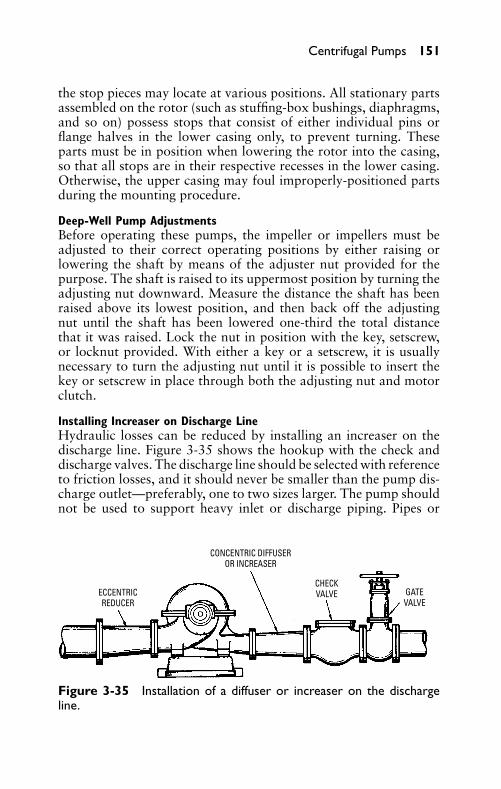
P1: FCH
GB098-03 GB098-Miller September 13, 2004 17:50 Char Count= 0
Centrifugal Pumps 151
the stop pieces may locate at various positions. All stationary partsassembled on the rotor (such as stuffing-box bushings, diaphragms,and so on) possess stops that consist of either individual pins orflange halves in the lower casing only, to prevent turning. Theseparts must be in position when lowering the rotor into the casing,so that all stops are in their respective recesses in the lower casing.Otherwise, the upper casing may foul improperly-positioned partsduring the mounting procedure.
Deep-Well Pump AdjustmentsBefore operating these pumps, the impeller or impellers must beadjusted to their correct operating positions by either raising orlowering the shaft by means of the adjuster nut provided for thepurpose. The shaft is raised to its uppermost position by turning theadjusting nut downward. Measure the distance the shaft has beenraised above its lowest position, and then back off the adjustingnut until the shaft has been lowered one-third the total distancethat it was raised. Lock the nut in position with the key, setscrew,or locknut provided. With either a key or a setscrew, it is usuallynecessary to turn the adjusting nut until it is possible to insert thekey or setscrew in place through both the adjusting nut and motorclutch.
Installing Increaser on Discharge LineHydraulic losses can be reduced by installing an increaser on thedischarge line. Figure 3-35 shows the hookup with the check anddischarge valves. The discharge line should be selected with referenceto friction losses, and it should never be smaller than the pump dis-charge outlet—preferably, one to two sizes larger. The pump shouldnot be used to support heavy inlet or discharge piping. Pipes or
ECCENTRICREDUCER
CONCENTRIC DIFFUSEROR INCREASER
CHECKVALVE GATE
VALVE
Figure 3-35 Installation of a diffuser or increaser on the dischargeline.
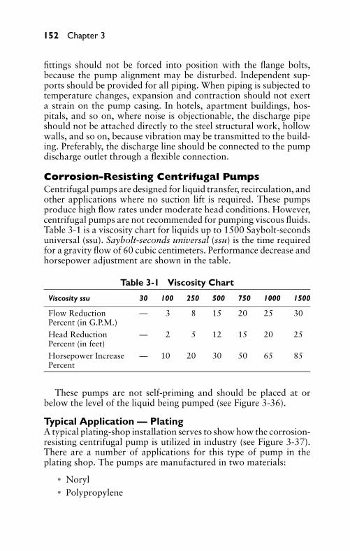
P1: FCH
GB098-03 GB098-Miller September 13, 2004 17:50 Char Count= 0
152 Chapter 3
fittings should not be forced into position with the flange bolts,because the pump alignment may be disturbed. Independent sup-ports should be provided for all piping. When piping is subjected totemperature changes, expansion and contraction should not exerta strain on the pump casing. In hotels, apartment buildings, hos-pitals, and so on, where noise is objectionable, the discharge pipeshould not be attached directly to the steel structural work, hollowwalls, and so on, because vibration may be transmitted to the build-ing. Preferably, the discharge line should be connected to the pumpdischarge outlet through a flexible connection.
Corrosion-Resisting Centrifugal PumpsCentrifugal pumps are designed for liquid transfer, recirculation, andother applications where no suction lift is required. These pumpsproduce high flow rates under moderate head conditions. However,centrifugal pumps are not recommended for pumping viscous fluids.Table 3-1 is a viscosity chart for liquids up to 1500 Saybolt-secondsuniversal (ssu). Saybolt-seconds universal (ssu) is the time requiredfor a gravity flow of 60 cubic centimeters. Performance decrease andhorsepower adjustment are shown in the table.
Table 3-1 Viscosity Chart
Viscosity ssu 30 100 250 500 750 1000 1500
Flow ReductionPercent (in G.P.M.)
— 3 8 15 20 25 30
Head ReductionPercent (in feet)
— 2 5 12 15 20 25
Horsepower IncreasePercent
— 10 20 30 50 65 85
These pumps are not self-priming and should be placed at orbelow the level of the liquid being pumped (see Figure 3-36).
Typical Application — PlatingA typical plating-shop installation serves to show how the corrosion-resisting centrifugal pump is utilized in industry (see Figure 3-37).There are a number of applications for this type of pump in theplating shop. The pumps are manufactured in two materials:
� Noryl� Polypropylene
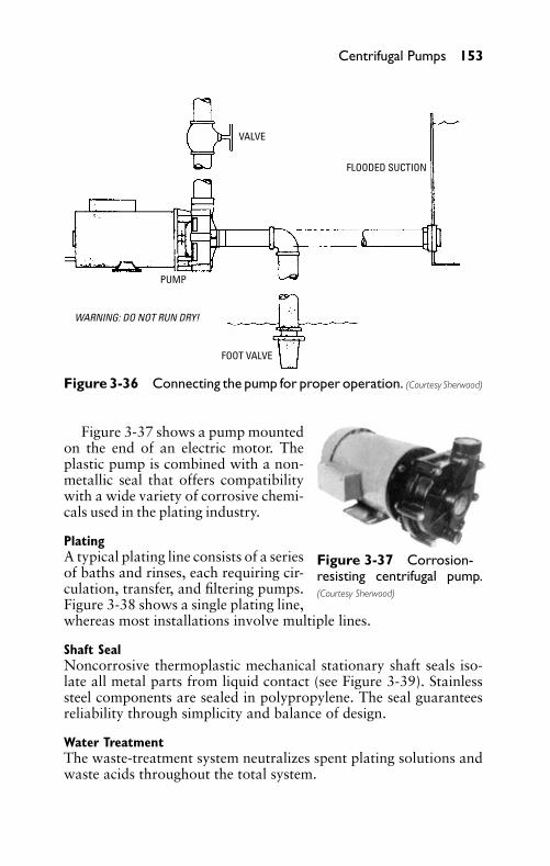
P1: FCH
GB098-03 GB098-Miller September 13, 2004 17:50 Char Count= 0
Centrifugal Pumps 153
VALVE
FOOT VALVE
FLOODED SUCTION
PUMP
WARNING: DO NOT RUN DRY!
Figure 3-36 Connecting the pump for proper operation. (Courtesy Sherwood)
Figure 3-37 Corrosion-resisting centrifugal pump.(Courtesy Sherwood)
Figure 3-37 shows a pump mountedon the end of an electric motor. Theplastic pump is combined with a non-metallic seal that offers compatibilitywith a wide variety of corrosive chemi-cals used in the plating industry.
PlatingA typical plating line consists of a seriesof baths and rinses, each requiring cir-culation, transfer, and filtering pumps.Figure 3-38 shows a single plating line,whereas most installations involve multiple lines.
Shaft SealNoncorrosive thermoplastic mechanical stationary shaft seals iso-late all metal parts from liquid contact (see Figure 3-39). Stainlesssteel components are sealed in polypropylene. The seal guaranteesreliability through simplicity and balance of design.
Water TreatmentThe waste-treatment system neutralizes spent plating solutions andwaste acids throughout the total system.
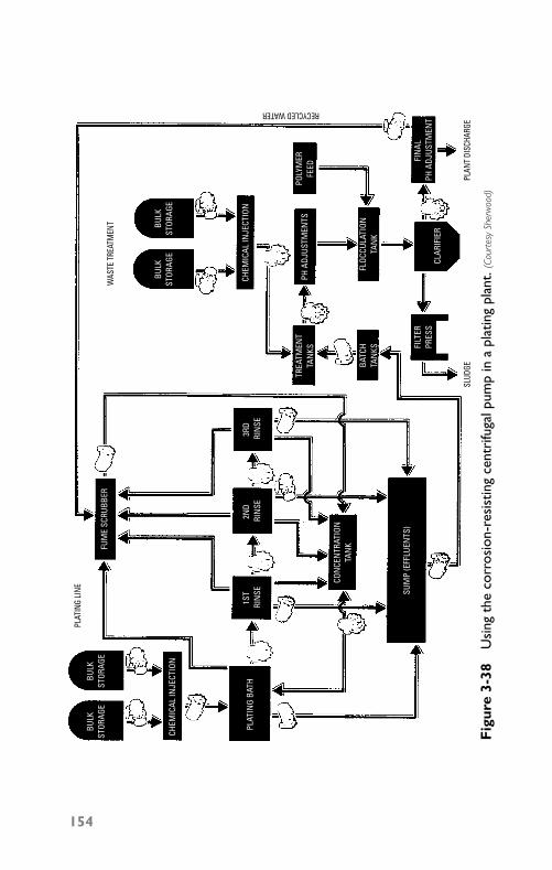
P1: FCH
GB098-03 GB098-Miller September 13, 2004 17:50 Char Count= 0
BULK
STOR
AGE
CHEM
ICAL
INJE
CTIO
N
CHEM
ICAL
INJE
CTIO
N
TREA
TMEN
TTA
NKS
BATC
HTA
NKS
FLOC
CULA
TION
TAN
K
PH A
DJUS
TMEN
TS
FIN
AL
PH A
DJUS
TMEN
T
POLY
MER
FEED
PLAT
ING
BATH
BULK
STOR
AGE
BULK
STOR
AGE
BULK
STOR
AGE
1ST
RIN
SE
CON
CEN
TRAT
ION
TAN
K
SUM
P (E
FFLU
ENTS
)
2ND
RIN
SE3R
D R
INSE
CLAR
IFIE
R
FILT
ERPR
ESS
FUM
E SC
RUBB
ER
PLAT
ING
LINE
SLUD
GEPL
ANT
DISC
HARG
E
WAS
TE T
REAT
MEN
T
RECYCLED WATER
Fig
ure
3-38
Usi
ngth
eco
rros
ion-
resi
stin
gce
ntri
fuga
lpum
pin
apl
atin
gpl
ant.
(Cou
rtes
ySh
erw
ood)
154
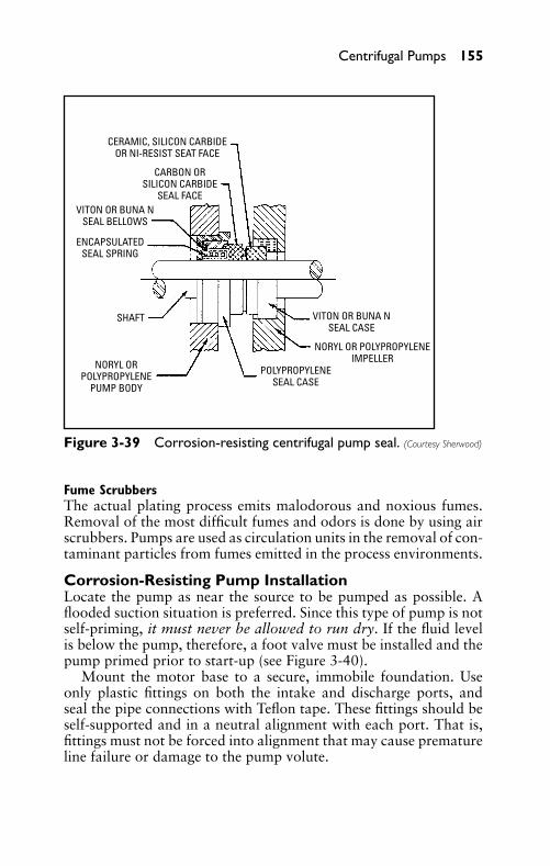
P1: FCH
GB098-03 GB098-Miller September 13, 2004 17:50 Char Count= 0
Centrifugal Pumps 155
CERAMIC, SILICON CARBIDEOR NI-RESIST SEAT FACE
CARBON ORSILICON CARBIDE
SEAL FACEVITON OR BUNA N
SEAL BELLOWS
VITON OR BUNA NSEAL CASE
SHAFT
NORYL ORPOLYPROPYLENE
PUMP BODY
NORYL OR POLYPROPYLENEIMPELLER
POLYPROPYLENESEAL CASE
ENCAPSULATEDSEAL SPRING
Figure 3-39 Corrosion-resisting centrifugal pump seal. (Courtesy Sherwood)
Fume ScrubbersThe actual plating process emits malodorous and noxious fumes.Removal of the most difficult fumes and odors is done by using airscrubbers. Pumps are used as circulation units in the removal of con-taminant particles from fumes emitted in the process environments.
Corrosion-Resisting Pump InstallationLocate the pump as near the source to be pumped as possible. Aflooded suction situation is preferred. Since this type of pump is notself-priming, it must never be allowed to run dry. If the fluid levelis below the pump, therefore, a foot valve must be installed and thepump primed prior to start-up (see Figure 3-40).
Mount the motor base to a secure, immobile foundation. Useonly plastic fittings on both the intake and discharge ports, andseal the pipe connections with Teflon tape. These fittings should beself-supported and in a neutral alignment with each port. That is,fittings must not be forced into alignment that may cause prematureline failure or damage to the pump volute.
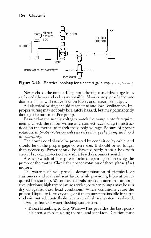
P1: FCH
GB098-03 GB098-Miller September 13, 2004 17:50 Char Count= 0
156 Chapter 3
VALVECIRCUITBREAKERBOX
CONDUIT
FOOT VALVE
FLOODEDSUCTION
PUMP
WARNING: DO NOT RUN DRY!
Figure 3-40 Electrical hook-up for a centrifugal pump. (Courtesy Sherwood)
Never choke the intake. Keep both the input and discharge linesas free of elbows and valves as possible. Always use pipe of adequatediameter. This will reduce friction losses and maximize output.
All electrical wiring should meet state and local ordinances. Im-proper wiring may not only be a safety hazard, but may permanentlydamage the motor and/or pump.
Ensure that the supply voltages match the pump motor’s require-ments. Check the motor wiring and connect (according to instruc-tions on the motor) to match the supply voltage. Be sure of properrotation. Improper rotation will severely damage the pump and voidthe warranty.
The power cord should be protected by conduit or by cable, andshould be of the proper gage or wire size. It should be no longerthan necessary. Power should be drawn directly from a box withcircuit breaker protection or with a fused disconnect switch.
Always switch off the power before repairing or servicing thepump or the motor. Check for proper rotation of three-phase (3�)motors.
The water flush will provide decontamination of chemicals orelastomers and seal and seat faces, while providing lubrication re-quired for start-up. Water-flushed seals are recommended for abra-sive solutions, high temperature service, or when pumps may be rundry or against dead head conditions. Where conditions cause thepumped liquid to form crystals, or if the pump remains idle for a pe-riod without adequate flushing, a water flush seal system is advised.
Two methods of water flushing can be used:� Direct Plumbing to City Water—This provides the best possi-
ble approach to flushing the seal and seat faces. Caution must
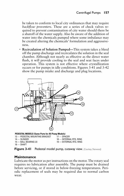
P1: FCH
GB098-03 GB098-Miller September 13, 2004 17:50 Char Count= 0
Centrifugal Pumps 157
be taken to conform to local city ordinances that may requirebackflow preventers. These are a series of check valves re-quired to prevent contamination of city water should there bea shutoff of the water supply. Also be aware of the addition ofwater into the chemicals pumped where some imbalance maybe created altering the chemicals’ formulation and aggressive-ness.
� Recirculation of Solution Pumped—This system takes a bleedoff the pump discharge and recirculates the solution in the sealchamber. Although not nearly as effective as the direct waterflush, it will provide cooling to the seal and seat faces underoperation. This system is not effective where crystallizationoccurs or for pumps in idle conditions. Figures 3-41 and 3-42show the pump intake and discharge and plug locations.
17
16
12
18
15
14
13
PEDESTAL MODELS (Same Parts for All Pump Models)13 — PEDESTAL MOUNTING BRACKET14 — SLINGER15 — BALL BEARING (2)16 — SHAFT
17 — SPACER18 — INTERNAL RTG. RING19 — EXTERNAL RTG. RING
Figure 3-41 Pedestal model pump, cutaway view. (Courtesy Sherwood)
MaintenanceLubricate the motor as per instructions on the motor. The rotary sealrequires no lubrication after assembly. The pump must be drainedbefore servicing, or if stored in below-freezing temperatures. Peri-odic replacement of seals may be required due to normal carbonwear.
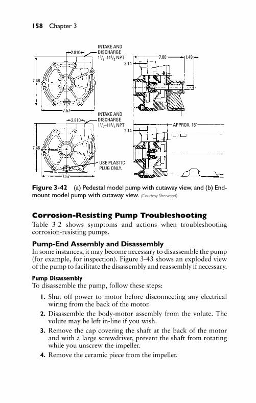
P1: FCH
GB098-03 GB098-Miller September 13, 2004 17:50 Char Count= 0
158 Chapter 3
7.46
7.46
2.810
2.810
7.57
7.57
INTAKE ANDDISCHARGE11/2–111/2 NPT
INTAKE ANDDISCHARGE11/2–111/2 NPT
USE PLASTICPLUG ONLY.
2.14
2.14
7.80 1.49
APPROX. 18"
Figure 3-42 (a) Pedestal model pump with cutaway view, and (b) End-mount model pump with cutaway view. (Courtesy Sherwood)
Corrosion-Resisting Pump TroubleshootingTable 3-2 shows symptoms and actions when troubleshootingcorrosion-resisting pumps.
Pump-End Assembly and DisassemblyIn some instances, it may become necessary to disassemble the pump(for example, for inspection). Figure 3-43 shows an exploded viewof the pump to facilitate the disassembly and reassembly if necessary.
Pump DisassemblyTo disassemble the pump, follow these steps:
1. Shut off power to motor before disconnecting any electricalwiring from the back of the motor.
2. Disassemble the body-motor assembly from the volute. Thevolute may be left in-line if you wish.
3. Remove the cap covering the shaft at the back of the motorand with a large screwdriver, prevent the shaft from rotatingwhile you unscrew the impeller.
4. Remove the ceramic piece from the impeller.
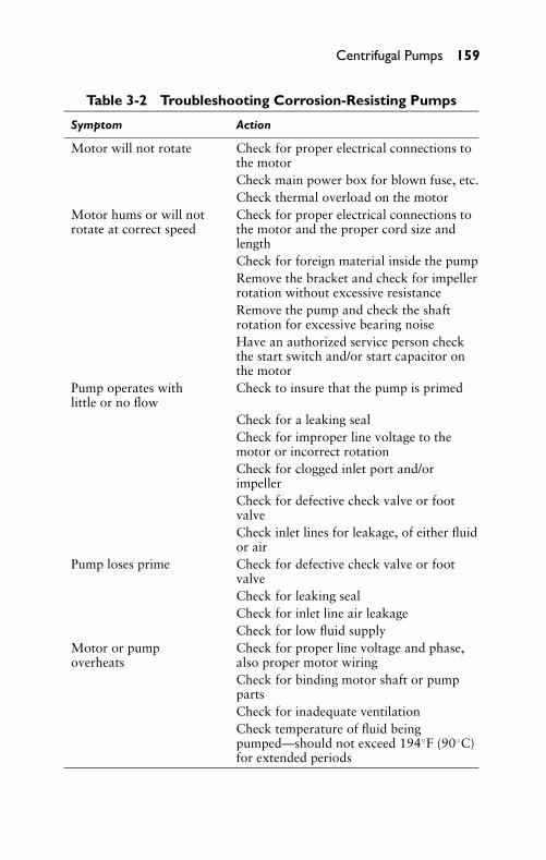
P1: FCH
GB098-03 GB098-Miller September 13, 2004 17:50 Char Count= 0
Centrifugal Pumps 159
Table 3-2 Troubleshooting Corrosion-Resisting Pumps
Symptom Action
Motor will not rotate Check for proper electrical connections tothe motorCheck main power box for blown fuse, etc.Check thermal overload on the motor
Motor hums or will notrotate at correct speed
Check for proper electrical connections tothe motor and the proper cord size andlengthCheck for foreign material inside the pumpRemove the bracket and check for impellerrotation without excessive resistanceRemove the pump and check the shaftrotation for excessive bearing noiseHave an authorized service person checkthe start switch and/or start capacitor onthe motor
Pump operates withlittle or no flow
Check to insure that the pump is primed
Check for a leaking sealCheck for improper line voltage to themotor or incorrect rotationCheck for clogged inlet port and/orimpellerCheck for defective check valve or footvalveCheck inlet lines for leakage, of either fluidor air
Pump loses prime Check for defective check valve or footvalveCheck for leaking sealCheck for inlet line air leakageCheck for low fluid supply
Motor or pumpoverheats
Check for proper line voltage and phase,also proper motor wiringCheck for binding motor shaft or pumppartsCheck for inadequate ventilationCheck temperature of fluid beingpumped—should not exceed 194◦F (90◦C)for extended periods
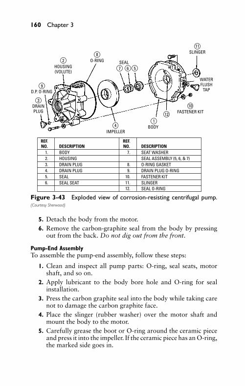
P1: FCH
GB098-03 GB098-Miller September 13, 2004 17:50 Char Count= 0
160 Chapter 3
DRAINPLUG
D.P. O-RING
HOUSING(VOLUTE)
O-RING
IMPELLERBODY
FASTENER KIT
WATERFLUSH
TAP
SEAL
SLINGER
3
9
8
6
11
10
121
4
57
2
REF.NO.
1.2.3.4.5.6.
BODYHOUSING
SEAL SEATSEALDRAIN PLUGDRAIN PLUG
SEAT WASHERSEAL ASSEMBLY (5, 6, & 7)
SLINGERSEAL O-RING
FASTENER KITDRAIN PLUG O-RINGO-RING GASKET
DESCRIPTION DESCRIPTION7.
8.9.
10.11.12.
REF.NO.
Figure 3-43 Exploded view of corrosion-resisting centrifugal pump.(Courtesy Sherwood)
5. Detach the body from the motor.6. Remove the carbon-graphite seal from the body by pressing
out from the back. Do not dig out from the front.
Pump-End AssemblyTo assemble the pump-end assembly, follow these steps:
1. Clean and inspect all pump parts: O-ring, seal seats, motorshaft, and so on.
2. Apply lubricant to the body bore hole and O-ring for sealinstallation.
3. Press the carbon graphite seal into the body while taking carenot to damage the carbon graphite face.
4. Place the slinger (rubber washer) over the motor shaft andmount the body to the motor.
5. Carefully grease the boot or O-ring around the ceramic pieceand press it into the impeller. If the ceramic piece has an O-ring,the marked side goes in.
P1: FCH
GB098-03 GB098-Miller September 13, 2004 17:50 Char Count= 0
Centrifugal Pumps 161
6. Sparingly lubricate carbon-graphite and ceramic sealing sur-faces with lightweight machine oil. Do not use silicon lubri-cants or grease.
7. Thread the impeller onto the shaft and tighten. If required,remove the motor end-cap and use a screwdriver on the backof the motor shaft to prevent shaft rotation while tightening.Replace the motor end-cap.
8. Electrically, connect the motor so that the impeller will rotatecounterclockwise (CCW) facing the pump with the motor to-ward the rear. Incorrect rotation will damage the pump andvoid the warranty.
NoteFor three-phase power, electrically check the rotation of the im-peller with the volute disassembled from the bracket. If the pump-end is assembled and the rotation is incorrect, serious damageto the pump-end assembly will occur and invalidate the warranty.If the rotation is incorrect, simply exchange any two leads to re-verse the direction of rotation.
9. Seat the O-ring in the volute slot and assemble the volute tothe body.
10. Install the drain plug in the volute drain hole.
Good Safety PracticesFollowing are some good safety tips:
� When wiring a motor, follow all local electrical and safetycodes, as well as the National Electrical Code (NEC) and theOccupational Safety and Health Act (OSHA).
� Always disconnect the power source before performing anywork on or near the motor or its connected load. If the powerdisconnect point is out of sight, lock the disconnect in the openposition and tag it to prevent unexpected application of power.Failure to do so could result in electrical shock.
� Be careful when touching the exterior of an operating motor. Itmay be hot enough to be painful or cause injury. With modernmotors, which are built to operate at higher temperatures, thiscondition is normal if operated at rated load and voltage.
� Do not insert any object into the motor.� Pump rotates in one direction only—counterclockwise from
the pump inlet end.
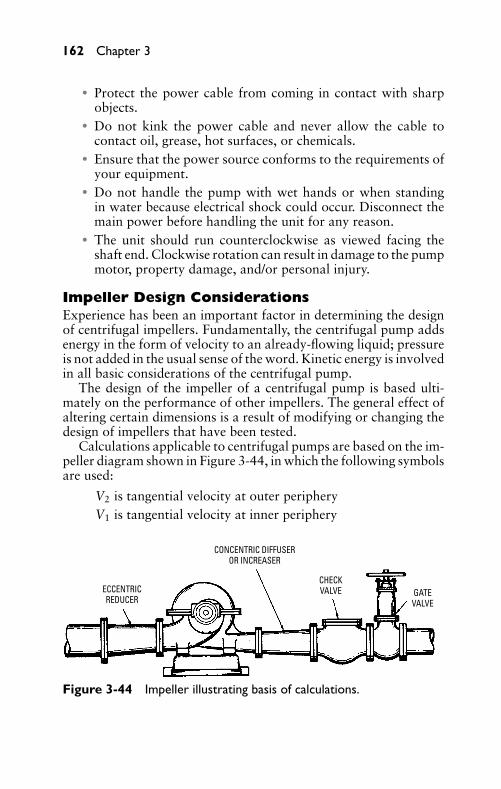
P1: FCH
GB098-03 GB098-Miller September 13, 2004 17:50 Char Count= 0
162 Chapter 3
� Protect the power cable from coming in contact with sharpobjects.
� Do not kink the power cable and never allow the cable tocontact oil, grease, hot surfaces, or chemicals.
� Ensure that the power source conforms to the requirements ofyour equipment.
� Do not handle the pump with wet hands or when standingin water because electrical shock could occur. Disconnect themain power before handling the unit for any reason.
� The unit should run counterclockwise as viewed facing theshaft end. Clockwise rotation can result in damage to the pumpmotor, property damage, and/or personal injury.
Impeller Design ConsiderationsExperience has been an important factor in determining the designof centrifugal impellers. Fundamentally, the centrifugal pump addsenergy in the form of velocity to an already-flowing liquid; pressureis not added in the usual sense of the word. Kinetic energy is involvedin all basic considerations of the centrifugal pump.
The design of the impeller of a centrifugal pump is based ulti-mately on the performance of other impellers. The general effect ofaltering certain dimensions is a result of modifying or changing thedesign of impellers that have been tested.
Calculations applicable to centrifugal pumps are based on the im-peller diagram shown in Figure 3-44, in which the following symbolsare used:
V2 is tangential velocity at outer peripheryV1 is tangential velocity at inner periphery
ECCENTRICREDUCER
CONCENTRIC DIFFUSEROR INCREASER
CHECKVALVE GATE
VALVE
Figure 3-44 Impeller illustrating basis of calculations.
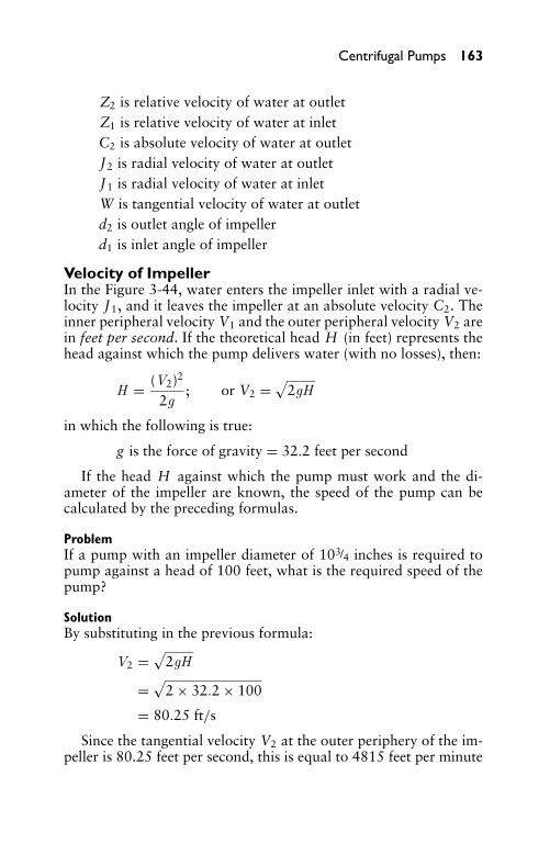
P1: FCH
GB098-03 GB098-Miller September 13, 2004 17:50 Char Count= 0
Centrifugal Pumps 163
Z2 is relative velocity of water at outletZ1 is relative velocity of water at inletC2 is absolute velocity of water at outletJ2 is radial velocity of water at outletJ1 is radial velocity of water at inletW is tangential velocity of water at outletd2 is outlet angle of impellerd1 is inlet angle of impeller
Velocity of ImpellerIn the Figure 3-44, water enters the impeller inlet with a radial ve-locity J1, and it leaves the impeller at an absolute velocity C2. Theinner peripheral velocity V1 and the outer peripheral velocity V2 arein feet per second. If the theoretical head H (in feet) represents thehead against which the pump delivers water (with no losses), then:
H = (V2)2
2g; or V2 =
√2gH
in which the following is true:
g is the force of gravity = 32.2 feet per second
If the head H against which the pump must work and the di-ameter of the impeller are known, the speed of the pump can becalculated by the preceding formulas.
ProblemIf a pump with an impeller diameter of 103/4 inches is required topump against a head of 100 feet, what is the required speed of thepump?
SolutionBy substituting in the previous formula:
V2 =√
2gH
=√
2 × 32.2 × 100
= 80.25 ft/s
Since the tangential velocity V2 at the outer periphery of the im-peller is 80.25 feet per second, this is equal to 4815 feet per minute
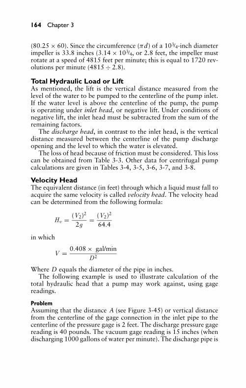
P1: FCH
GB098-03 GB098-Miller September 13, 2004 17:50 Char Count= 0
164 Chapter 3
(80.25 × 60). Since the circumference (πd) of a 103/4-inch diameterimpeller is 33.8 inches (3.14 × 10³/4, or 2.8 feet, the impeller mustrotate at a speed of 4815 feet per minute; this is equal to 1720 rev-olutions per minute (4815 ÷ 2.8).
Total Hydraulic Load or LiftAs mentioned, the lift is the vertical distance measured from thelevel of the water to be pumped to the centerline of the pump inlet.If the water level is above the centerline of the pump, the pumpis operating under inlet head, or negative lift. Under conditions ofnegative lift, the inlet head must be subtracted from the sum of theremaining factors.
The discharge head, in contrast to the inlet head, is the verticaldistance measured between the centerline of the pump dischargeopening and the level to which the water is elevated.
The loss of head because of friction must be considered. This losscan be obtained from Table 3-3. Other data for centrifugal pumpcalculations are given in Tables 3-4, 3-5, 3-6, 3-7, and 3-8.
Velocity HeadThe equivalent distance (in feet) through which a liquid must fall toacquire the same velocity is called velocity head. The velocity headcan be determined from the following formula:
Hv = (V2)2
2g= (V2)2
64.4
in which
V = 0.408 × gal/minD2
Where D equals the diameter of the pipe in inches.The following example is used to illustrate calculation of the
total hydraulic head that a pump may work against, using gagereadings.
ProblemAssuming that the distance A (see Figure 3-45) or vertical distancefrom the centerline of the gage connection in the inlet pipe to thecenterline of the pressure gage is 2 feet. The discharge pressure gagereading is 40 pounds. The vacuum gage reading is 15 inches (whendischarging 1000 gallons of water per minute). The discharge pipe is
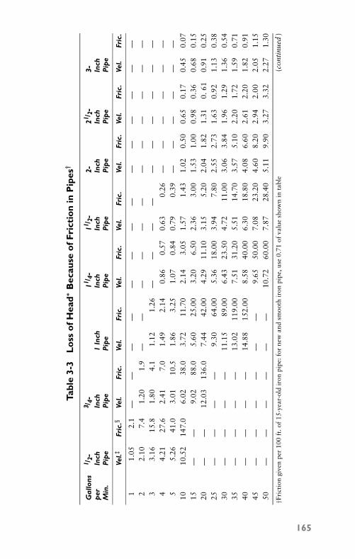
P1: FCH
GB098-03 GB098-Miller September 13, 2004 17:50 Char Count= 0
Tabl
e3-
3L
oss
ofH
ead∗
Bec
ause
ofF
rict
ion
inP
ipes
†
Gal
lons
1 /2-
3 /4-
11 /4-
11 /2-
2-21 /
2-3-
per
Inch
Inch
1In
chIn
chIn
chIn
chIn
chIn
chM
in.
Pip
eP
ipe
Pip
eP
ipe
Pip
eP
ipe
Pip
eP
ipe
Vel.‡
Fric
.§Ve
l.Fr
ic.
Vel.
Fric
.Ve
l.Fr
ic.
Vel.
Fric
.Ve
l.Fr
ic.
Vel.
Fric
.Ve
l.Fr
ic.
11.
052.
1—
——
——
——
——
——
——
—2
2.10
7.4
1.20
1.9
——
——
——
——
——
——
33.
1615
.81.
804.
11.
121.
26—
——
——
——
——
—4
4.21
27.6
2.41
7.0
1.49
2.14
0.86
0.57
0.63
0.26
——
——
——
55.
2641
.03.
0110
.51.
863.
251.
070.
840.
790.
39—
——
——
—10
10.5
214
7.0
6.02
38.0
3.72
11.7
02.
143.
051.
571.
431.
020.
500.
650.
170.
450.
0715
——
9.02
88.0
5.60
25.0
03.
206.
502.
363.
001.
531.
000.
980.
360.
680.
1520
——
12.0
313
6.0
7.44
42.0
04.
2911
.10
3.15
5.20
2.04
1.82
1.31
0.61
0.91
0.25
25—
——
—9.
3064
.00
5.36
18.0
03.
947.
802.
552.
731.
630.
921.
130.
3830
——
——
11.1
589
.00
6.43
23.5
04.
7211
.00
3.06
3.84
1.96
1.29
1.36
0.54
35—
——
—13
.02
119.
007.
5131
.20
5.51
14.7
03.
575.
102.
201.
721.
590.
7140
——
——
14.8
815
2.00
8.58
40.0
06.
3018
.80
4.08
6.60
2.61
2.20
1.82
0.91
45—
——
——
—9.
6550
.00
7.08
23.2
04.
608.
202.
942.
002.
051.
1550
——
——
——
10.7
260
.00
7.87
28.4
05.
119.
903.
273.
322.
271.
30
(con
tinu
ed)
†Fri
ctio
ngi
ven
per
100
ft.o
f15
-yea
r-ol
dir
onpi
pe: f
orne
wan
dsm
ooth
iron
pipe
,use
0.71
ofva
lue
show
nin
tabl
e
165
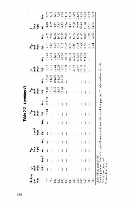
P1: FCH
GB098-03 GB098-Miller September 13, 2004 17:50 Char Count= 0
Tabl
e3-
3(c
onti
nued
)
Gal
lons
1 /2-
3 /4-
11 /4-
11 /2-
2-21 /
2-3
per
Inch
Inch
1In
chIn
chIn
chIn
chIn
chIn
chM
in.
Pip
eP
ipe
Pip
eP
ipe
Pip
eP
ipe
Pip
eP
ipe
Vel.‡
Fric
.§Ve
l.Fr
ic.
Vel.
Fric
.Ve
l.Fr
ic.
Vel.
Fric
.Ve
l.Fr
ic.
Vel.
Fric
.Ve
l.Fr
ic.
70—
——
——
—15
.01
113.
0011
.02
53.0
07.
1518
.40
4.58
6.20
3.18
2.57
90—
——
——
——
—14
.17
84.0
09.
1928
.40
5.88
9.00
4.09
4.08
100
——
——
——
——
15.7
410
2.00
10.2
135
.00
6.54
12.0
04.
544.
9612
0—
——
——
——
—18
.89
143.
0012
.25
50.0
07.
8416
.80
5.45
7.00
140
——
——
——
——
22.0
419
9.00
14.3
067
.00
9.15
23.3
06.
359.
2016
0—
——
——
——
——
—16
.34
86.0
010
.46
29.0
07.
2611
.00
180
——
——
——
——
——
18.3
810
7.00
11.7
636
.70
8.17
14.8
020
0—
——
——
——
——
—20
.42
129.
0013
.07
43.1
09.
0817
.80
220
——
——
——
——
——
22.4
715
4.00
14.3
852
.00
9.99
21.3
024
0—
——
——
——
——
—24
.51
182.
0015
.69
61.0
010
.89
26.1
026
0—
——
——
——
——
—26
.55
211.
0016
.99
70.0
011
.80
29.1
028
0—
——
——
——
——
——
—18
.30
81.0
012
.71
33.4
030
0—
——
——
——
——
——
—19
.61
92.0
013
.62
38.0
0∗
Los
sof
head
give
nin
feet
†Fri
ctio
ngi
ven
per
100
ft.o
f15
-yea
r-ol
dir
onpi
pe: f
orne
wan
dsm
ooth
iron
pipe
,use
0.71
ofva
lue
show
nin
tabl
e‡V
eloc
ity
feet
per
seco
nd§F
rict
ion
head
infe
et
166
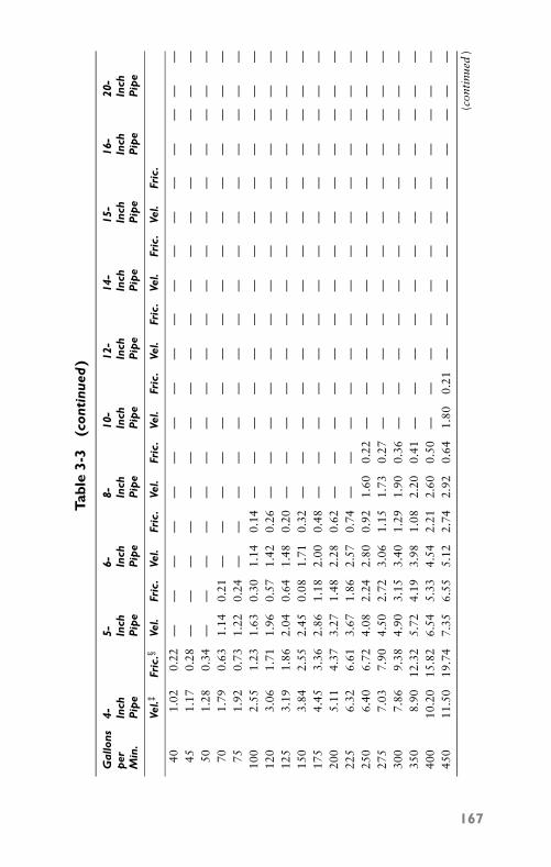
P1: FCH
GB098-03 GB098-Miller September 13, 2004 17:50 Char Count= 0
Tabl
e3-
3(c
onti
nued
)
Gal
lons
4-5-
6-8-
10-
12-
14-
15-
16-
20-
per
Inch
Inch
Inch
Inch
Inch
Inch
Inch
Inch
Inch
Inch
Min
.P
ipe
Pip
eP
ipe
Pip
eP
ipe
Pip
eP
ipe
Pip
eP
ipe
Pip
e
Vel.‡
Fric
.§Ve
l.Fr
ic.
Vel.
Fric
.Ve
l.Fr
ic.
Vel.
Fric
.Ve
l.Fr
ic.
Vel.
Fric
.Ve
l.Fr
ic.
401.
020.
22—
——
——
——
——
——
——
——
——
—45
1.17
0.28
——
——
——
——
——
——
——
——
——
501.
280.
34—
——
——
——
——
——
——
——
——
—70
1.79
0.63
1.14
0.21
——
——
——
——
——
——
——
——
751.
920.
731.
220.
24—
——
——
——
——
——
——
——
—10
02.
551.
231.
630.
301.
140.
14—
——
——
——
——
——
——
—12
03.
061.
711.
960.
571.
420.
26—
——
——
——
——
——
——
—12
53.
191.
862.
040.
641.
480.
20—
——
——
——
——
——
——
—15
03.
842.
552.
450.
081.
710.
32—
——
——
——
——
——
——
—17
54.
453.
362.
861.
182.
000.
48—
——
——
——
——
——
——
—20
05.
114.
373.
271.
482.
280.
62—
——
——
——
——
——
——
—22
56.
326.
613.
671.
862.
570.
74—
——
——
——
——
——
——
—25
06.
406.
724.
082.
242.
800.
921.
600.
22—
——
——
——
——
——
—27
57.
037.
904.
502.
723.
061.
151.
730.
27—
——
——
——
——
——
—30
07.
869.
384.
903.
153.
401.
291.
900.
36—
——
——
——
——
——
—35
08.
9012
.32
5.72
4.19
3.98
1.08
2.20
0.41
——
——
——
——
——
——
400
10.2
015
.82
6.54
5.33
4.54
2.21
2.60
0.50
——
——
——
——
——
——
450
11.5
019
.74
7.35
6.55
5.12
2.74
2.92
0.64
1.80
0.21
——
——
——
——
——
(con
tinu
ed)
167
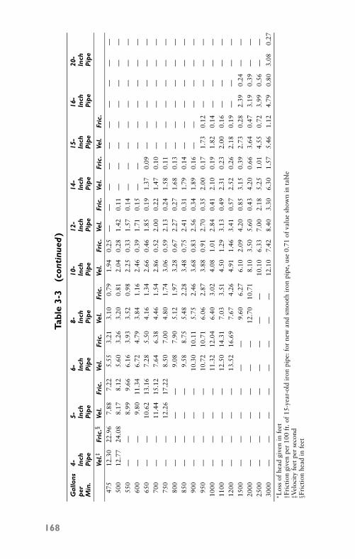
P1: FCH
GB098-03 GB098-Miller September 13, 2004 17:50 Char Count= 0
Tabl
e3-
3(c
onti
nued
)
Gal
lons
4-5-
6-8-
10-
12-
14-
15-
16-
20-
per
Inch
Inch
Inch
Inch
Inch
Inch
Inch
Inch
Inch
Inch
Min
.P
ipe
Pip
eP
ipe
Pip
eP
ipe
Pip
eP
ipe
Pip
eP
ipe
Pip
e
Vel.‡
Fric
.§Ve
l.Fr
ic.
Vel.
Fric
.Ve
l.Fr
ic.
Vel.
Fric
.Ve
l.Fr
ic.
Vel.
Fric
.Ve
l.Fr
ic.
475
12.3
022
.96
7.88
7.22
5.55
3.21
3.10
0.79
1.94
0.25
——
——
——
——
——
500
12.7
724
.08
8.17
8.12
5.60
3.26
3.20
0.81
2.04
0.28
1.42
0.11
——
——
——
——
550
——
8.99
9.66
6.16
3.93
3.52
0.98
2.25
0.33
1.57
0.14
——
——
——
——
600
——
9.80
11.3
46.
724.
793.
841.
162.
460.
391.
710.
15—
——
——
——
—65
0—
—10
.62
13.1
67.
285.
504.
161.
342.
660.
461.
850.
191.
370.
09—
——
——
—70
0—
—11
.44
15.1
27.
646.
384.
461.
542.
860.
522.
000.
221.
470.
10—
——
——
—75
0—
—12
.26
17.2
28.
507.
004.
801.
743.
060.
592.
130.
241.
580.
11—
——
——
—80
0—
——
—9.
087.
905.
121.
973.
280.
672.
270.
271.
680.
13—
——
——
—85
0—
——
—9.
588.
755.
482.
283.
480.
752.
410.
311.
790.
14—
——
——
—90
0—
——
—10
.30
10.1
15.
752.
463.
680.
832.
560.
341.
890.
16—
——
——
—95
0—
——
—10
.72
10.7
16.
062.
873.
880.
912.
700.
352.
000.
171.
730.
12—
——
—10
00—
——
—11
.32
12.0
46.
403.
024.
081.
012.
840.
412.
100.
191.
820.
14—
——
—11
00—
——
—12
.50
14.3
17.
033.
514.
501.
293.
130.
492.
310.
232.
000.
16—
——
—12
00—
——
—13
.52
16.6
97.
674.
264.
911.
463.
410.
572.
520.
262.
180.
19—
——
—15
00—
——
——
—9.
606.
276.
102.
094.
200.
853.
150.
392.
730.
282.
390.
24—
—20
00—
——
——
—12
.70
10.7
18.
103.
505.
600.
434.
200.
663.
640.
473.
190.
39—
—25
00—
——
——
——
—10
.10
6.33
7.00
2.18
5.25
1.01
4.55
0.72
3.99
0.56
——
3000
——
——
——
——
12.1
07.
428.
403.
306.
301.
575.
461.
124.
790.
803.
080.
27∗ L
oss
ofhe
adgi
ven
infe
et†F
rict
ion
give
npe
r10
0ft
.of
15-y
ear-
old
iron
pipe
:for
new
and
smoo
thir
onpi
pe,u
se0.
71of
valu
esh
own
inta
ble
‡Vel
ocit
yfe
etpe
rse
cond
§Fri
ctio
nhe
adin
feet
168
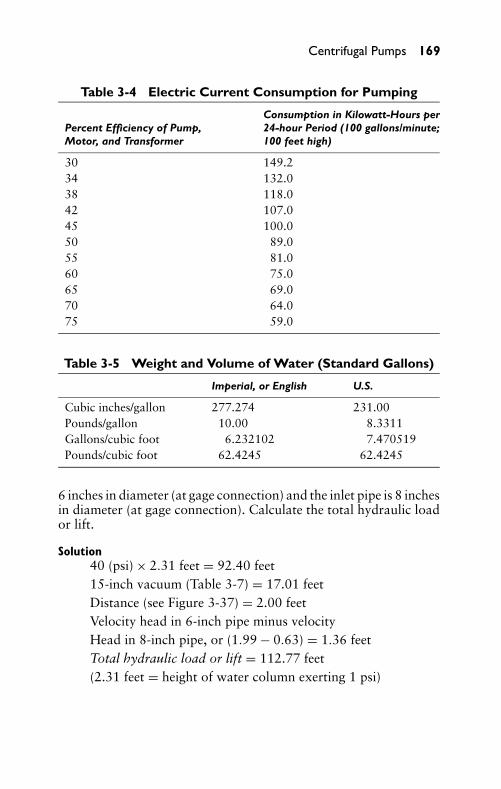
P1: FCH
GB098-03 GB098-Miller September 13, 2004 17:50 Char Count= 0
Centrifugal Pumps 169
Table 3-4 Electric Current Consumption for Pumping
Consumption in Kilowatt-Hours perPercent Efficiency of Pump, 24-hour Period (100 gallons/minute;Motor, and Transformer 100 feet high)
30 149.234 132.038 118.042 107.045 100.050 89.055 81.060 75.065 69.070 64.075 59.0
Table 3-5 Weight and Volume of Water (Standard Gallons)
Imperial, or English U.S.
Cubic inches/gallon 277.274 231.00Pounds/gallon 10.00 8.3311Gallons/cubic foot 6.232102 7.470519Pounds/cubic foot 62.4245 62.4245
6 inches in diameter (at gage connection) and the inlet pipe is 8 inchesin diameter (at gage connection). Calculate the total hydraulic loador lift.
Solution40 (psi) × 2.31 feet = 92.40 feet15-inch vacuum (Table 3-7) = 17.01 feetDistance (see Figure 3-37) = 2.00 feetVelocity head in 6-inch pipe minus velocityHead in 8-inch pipe, or (1.99 − 0.63) = 1.36 feetTotal hydraulic load or lift = 112.77 feet(2.31 feet = height of water column exerting 1 psi)
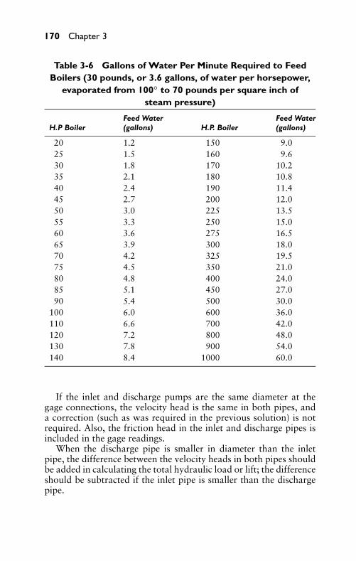
P1: FCH
GB098-03 GB098-Miller September 13, 2004 17:50 Char Count= 0
170 Chapter 3
Table 3-6 Gallons of Water Per Minute Required to FeedBoilers (30 pounds, or 3.6 gallons, of water per horsepower,
evaporated from 100◦ to 70 pounds per square inch ofsteam pressure)
Feed Water Feed WaterH.P Boiler (gallons) H.P. Boiler (gallons)
20 1.2 150 9.025 1.5 160 9.630 1.8 170 10.235 2.1 180 10.840 2.4 190 11.445 2.7 200 12.050 3.0 225 13.555 3.3 250 15.060 3.6 275 16.565 3.9 300 18.070 4.2 325 19.575 4.5 350 21.080 4.8 400 24.085 5.1 450 27.090 5.4 500 30.0
100 6.0 600 36.0110 6.6 700 42.0120 7.2 800 48.0130 7.8 900 54.0140 8.4 1000 60.0
If the inlet and discharge pumps are the same diameter at thegage connections, the velocity head is the same in both pipes, anda correction (such as was required in the previous solution) is notrequired. Also, the friction head in the inlet and discharge pipes isincluded in the gage readings.
When the discharge pipe is smaller in diameter than the inletpipe, the difference between the velocity heads in both pipes shouldbe added in calculating the total hydraulic load or lift; the differenceshould be subtracted if the inlet pipe is smaller than the dischargepipe.
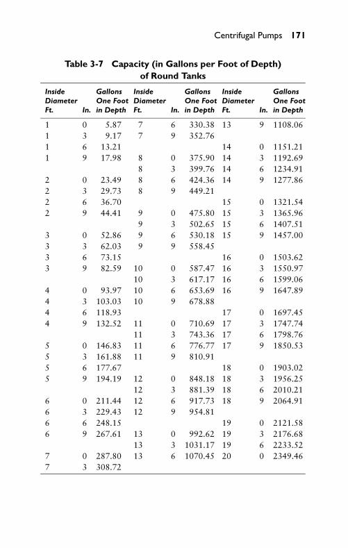
P1: FCH
GB098-03 GB098-Miller September 13, 2004 17:50 Char Count= 0
Centrifugal Pumps 171
Table 3-7 Capacity (in Gallons per Foot of Depth)of Round Tanks
Inside Gallons Inside Gallons Inside GallonsDiameter One Foot Diameter One Foot Diameter One FootFt. In. in Depth Ft. In. in Depth Ft. In. in Depth
1 0 5.87 7 6 330.38 13 9 1108.061 3 9.17 7 9 352.761 6 13.21 14 0 1151.211 9 17.98 8 0 375.90 14 3 1192.69
8 3 399.76 14 6 1234.912 0 23.49 8 6 424.36 14 9 1277.862 3 29.73 8 9 449.212 6 36.70 15 0 1321.542 9 44.41 9 0 475.80 15 3 1365.96
9 3 502.65 15 6 1407.513 0 52.86 9 6 530.18 15 9 1457.003 3 62.03 9 9 558.453 6 73.15 16 0 1503.623 9 82.59 10 0 587.47 16 3 1550.97
10 3 617.17 16 6 1599.064 0 93.97 10 6 653.69 16 9 1647.894 3 103.03 10 9 678.884 6 118.93 17 0 1697.454 9 132.52 11 0 710.69 17 3 1747.74
11 3 743.36 17 6 1798.765 0 146.83 11 6 776.77 17 9 1850.535 3 161.88 11 9 810.915 6 177.67 18 0 1903.025 9 194.19 12 0 848.18 18 3 1956.25
12 3 881.39 18 6 2010.216 0 211.44 12 6 917.73 18 9 2064.916 3 229.43 12 9 954.816 6 248.15 19 0 2121.586 9 267.61 13 0 992.62 19 3 2176.68
13 3 1031.17 19 6 2233.527 0 287.80 13 6 1070.45 20 0 2349.467 3 308.72
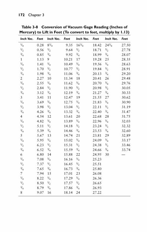
P1: FCH
GB098-03 GB098-Miller September 13, 2004 17:50 Char Count= 0
172 Chapter 3
Table 3-8 Conversion of Vacuum Gage Reading (Inches ofMercury) to Lift in Feet (To convert to feet, multiply by 1.13)
Inch Vac. Feet Inch Vac. Feet Inch Vac. Feet Inch Vac. Feet
1/4 0.28 81/4 9.35 161/4 18.42 241/4 27.501/2 0.56 1/2 9.64 1/2 18.71 1/2 27.783/4 0.85 3/4 9.92 3/4 18.99 3/4 28.071 1.13 9 10.21 17 19.28 25 28.351/4 1.41 1/4 10.49 1/4 19.56 1/4 28.631/2 1.70 1/2 10.77 1/2 19.84 1/2 28.913/4 1.98 3/4 11.06 3/4 20.13 3/4 29.202 2.27 10 11.34 18 20.41 26 29.481/4 2.55 1/4 11.62 1/4 20.70 1/4 29.761/2 2.84 1/2 11.90 1/2 20.98 1/2 30.053/4 3.12 3/4 12.19 3/4 21.27 3/4 30.333 3.41 11 12.47 19 21.55 27 30.621/4 3.69 1/4 12.75 1/4 21.83 1/4 30.901/2 3.98 1/2 13.04 1/2 22.11 1/2 31.193/4 4.26 3/4 13.32 3/4 22.40 3/4 31.474 4.54 12 13.61 20 22.68 28 31.751/4 4.82 1/4 13.89 1/4 22.96 1/4 32.031/2 5.11 1/2 14.18 1/2 23.24 1/2 32.323/4 5.39 3/4 14.46 3/4 23.53 3/4 32.605 5.67 13 14.74 21 23.81 29 32.891/4 5.95 1/4 15.02 1/4 24.09 1/4 33.171/2 6.23 1/2 15.31 1/2 24.38 1/2 33.463/4 6.52 3/4 15.59 3/4 24.66 3/4 33.746 6.80 14 15.88 22 24.95 30 —1/4 7.08 1/4 16.16 1/4 25.231/2 7.37 1/2 16.45 1/2 25.513/4 7.65 3/4 16.73 3/4 25.807 7.94 15 17.01 23 26.081/4 8.22 1/4 17.29 1/4 26.361/2 8.50 1/2 17.57 1/2 26.653/4 8.79 3/4 17.86 3/4 26.938 9.07 16 18.14 24 27.22
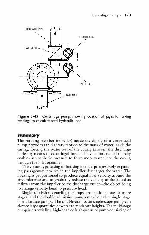
P1: FCH
GB098-03 GB098-Miller September 13, 2004 17:50 Char Count= 0
Centrifugal Pumps 173
DISCHARGE PIPE
PRESSURE GAGE
INLET GAGE
INLET PIPE
GATE VALVE
A
Figure 3-45 Centrifugal pump, showing location of gages for takingreadings to calculate total hydraulic load.
SummaryThe rotating member (impeller) inside the casing of a centrifugalpump provides rapid rotary motion to the mass of water inside thecasing, forcing the water out of the casing through the dischargeoutlet by means of centrifugal force. The vacuum created therebyenables atmospheric pressure to force more water into the casingthrough the inlet opening.
The volute-type casing or housing forms a progressively expand-ing passageway into which the impeller discharges the water. Thehousing is proportioned to produce equal flow velocity around thecircumference and to gradually reduce the velocity of the liquid asit flows from the impeller to the discharge outlet—the object beingto change velocity head to pressure head.
Single-admission centrifugal pumps are made in one or morestages, and the double-admission pumps may be either single-stageor multistage pumps. The double-admission single-stage pump canelevate large quantities of water to moderate heights. The multistagepump is essentially a high-head or high-pressure pump consisting of
P1: FCH
GB098-03 GB098-Miller September 13, 2004 17:50 Char Count= 0
174 Chapter 3
two or more stages, depending on the size of the head that it isto pump against. There may be as many as eight stages in a singlecasing.
The efficiency of a centrifugal pump is determined by the type ofimpeller. Three types of vanes are found on impellers: open, semi-open, and enclosed (or shrouded), depending on the service, desiredefficiency, and cost. The enclosed-type impeller is generally consid-ered a more efficient impeller. The vanes are cast integrally on bothsides and are designed to prevent packing of fibrous materials be-tween the stationary cover and the rotating impeller.
A centrifugal pump should not be operated unless it is filled withliquid. If it is run without liquid, there is danger of damage to theliquid-lubricated internal parts. Three methods of priming are theejector method, the hand-type lift pump (or powered air pump),and the foot-valve and top-discharge method. Automatic primingsystems, such as the float-controlled and the reserve vacuum tank-types, are used on some pumps.
Liberal clearances are provided between the rotating and station-ary pump parts to allow for small matching variations and for theexpansion of the casing and rotor when they become heated. Station-ary diaphragms, wearing rings, return channels, and so on (whichare located in the casing) are slightly smaller in diameter than thecasing bore, which is machined for a gasket between the flanges.
If the level of the water supply is above the centerline of the pump,the pump is operating under inlet head. The discharge head is thevertical distance measured between the centerline of the pump andthe level to which the water is elevated.
Review Questions1. What is the basic operating principle of the centrifugal pump?2. How is the volute-type casing proportional?3. List three types of impeller vanes.4. What is the chief advantage of the double-admission type of
single-stage pump?5. For what type of service is the multistage pump adapted?6. For what types of service is the axial-flow type of impeller
adapted?7. In what direction does centrifugal force move objects?8. What is the difference between a vane and impeller?9. What is meant by the eye of the impeller?
P1: FCH
GB098-03 GB098-Miller September 13, 2004 17:50 Char Count= 0
Centrifugal Pumps 175
10. Where does the volute pump get its name?11. What is the difference between a single- and double-admission
pump?12. What determines the efficiency of a centrifugal pump?13. For what is the open type of vane best suited?14. How is natural balancing achieved in single-stage pumps?15. How is mechanical balancing in a centrifugal pump achieved?16. What is a stuffing box on a pump?17. What type of drive is used on centrifugal pumps?18. What type of thrust bearings do multistage pumps use?19. Why is it important to make sure the direction of rotation on
a centrifugal pump impeller is correct?20. List three methods used to prime centrifugal pumps.21. What is gland packing?22. Where is graphite packing utilized?23. What causes pump vibration?24. List four reasons why a pump may have a reduced capacity, a
reduced pressure, or a failure to deliver water.25. What causes a pump to lose water after starting?

P1: FCH
GB098-03 GB098-Miller September 13, 2004 17:50 Char Count= 0
176
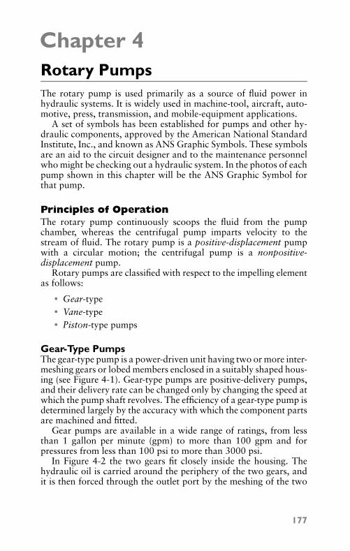
P1: FCH
GB098-04 GB098-Miller September 13, 2004 14:26 Char Count= 0
Chapter 4Rotary PumpsThe rotary pump is used primarily as a source of fluid power inhydraulic systems. It is widely used in machine-tool, aircraft, auto-motive, press, transmission, and mobile-equipment applications.
A set of symbols has been established for pumps and other hy-draulic components, approved by the American National StandardInstitute, Inc., and known as ANS Graphic Symbols. These symbolsare an aid to the circuit designer and to the maintenance personnelwho might be checking out a hydraulic system. In the photos of eachpump shown in this chapter will be the ANS Graphic Symbol forthat pump.
Principles of OperationThe rotary pump continuously scoops the fluid from the pumpchamber, whereas the centrifugal pump imparts velocity to thestream of fluid. The rotary pump is a positive-displacement pumpwith a circular motion; the centrifugal pump is a nonpositive-displacement pump.
Rotary pumps are classified with respect to the impelling elementas follows:
� Gear-type� Vane-type� Piston-type pumps
Gear-Type PumpsThe gear-type pump is a power-driven unit having two or more inter-meshing gears or lobed members enclosed in a suitably shaped hous-ing (see Figure 4-1). Gear-type pumps are positive-delivery pumps,and their delivery rate can be changed only by changing the speed atwhich the pump shaft revolves. The efficiency of a gear-type pump isdetermined largely by the accuracy with which the component partsare machined and fitted.
Gear pumps are available in a wide range of ratings, from lessthan 1 gallon per minute (gpm) to more than 100 gpm and forpressures from less than 100 psi to more than 3000 psi.
In Figure 4-2 the two gears fit closely inside the housing. Thehydraulic oil is carried around the periphery of the two gears, andit is then forced through the outlet port by the meshing of the two
177
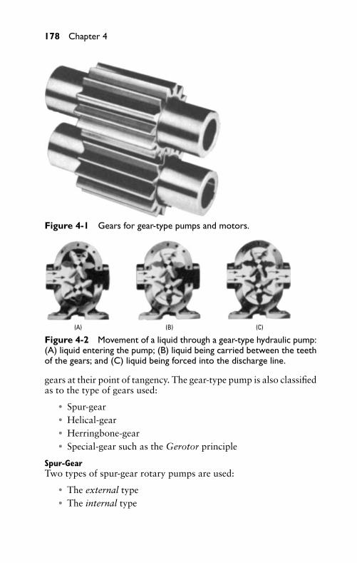
P1: FCH
GB098-04 GB098-Miller September 13, 2004 14:26 Char Count= 0
178 Chapter 4
Figure 4-1 Gears for gear-type pumps and motors.
(A) (B) (C)
Figure 4-2 Movement of a liquid through a gear-type hydraulic pump:(A) liquid entering the pump; (B) liquid being carried between the teethof the gears; and (C) liquid being forced into the discharge line.
gears at their point of tangency. The gear-type pump is also classifiedas to the type of gears used:
� Spur-gear� Helical-gear� Herringbone-gear� Special-gear such as the Gerotor principle
Spur-GearTwo types of spur-gear rotary pumps are used:
� The external type� The internal type
P1: FCH
GB098-04 GB098-Miller September 13, 2004 14:26 Char Count= 0
Rotary Pumps 179
In operation of the external type of gear pump, vacuum spacesform as each pair of meshing teeth separates, and atmospheric pres-sure forces the liquid inward to fill the spaces. The liquid filling thespace between two adjacent teeth follows along with them. This hap-pens as they revolve and it is forced outward through the dischargeopening. That is because the meshing of the teeth during rotationforms a seal that separates the admission and discharge portions ofthe secondary chamber (see Figure 4-2).
In operation of the internal-gear type of rotary pump, power isapplied to the rotor and transferred to the idler gear with whichit meshes. As the teeth come out of mesh, an increase in volumecreates a partial vacuum. Liquid is forced into this space by atmo-spheric pressure and remains between the teeth of the rotor andidler until the teeth mesh to force the liquid from these spaces andout of the pump. The internal-gear type of rotary pump shownin Figure 4-3 and Figure 4-4 possesses only two moving parts:the precision-cut rotor and idler gears. As shown in the cross-sectional view of the pump, the teeth of the internal gear and idlergear separate at the suction port and mesh again at the dischargeport.
Shaft rotation will determine which port is suction and whichport is discharge. A look at Figure 4-3 will show how rotation de-termines which port is which. As the pumping elements (gears) comeout of mesh, point A, liquid is drawn into the suction port; as thegears come into mesh, point B, the liquid is forced out the dischargeport. Reversing the rotation reverses the flow through the pump.When determining shaft rotation, always look from the shaft endof the pump. Unless otherwise specified, rotation is assumed clock-wise (CW), which makes the suction port on the right side of thepump.
Internal and external gear-shaped elements are combined in theGerotor mechanism (see Figure 4-5). In the Gerotor mechanism,the tooth form of the inner Gerotor is generated from the toothform of the outer Gerotor, so that each tooth of the inner Gerotoris in sliding contact with the outer Gerotor at all times, providingcontinuous fluid-tight engagement. As the teeth disengage, the spacebetween them increases in size, creating a partial vacuum into whichthe liquid flows from the suction port to which the enlarging toothspace is exposed. When the chamber reaches its maximum volume,it is exposed to the discharge port. As the chamber diminishes insize because of meshing of the teeth, the liquid is forced from thepump. The various parts of the Gerotor pump are shown in Fig-ure 4-6.
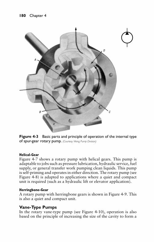
P1: FCH
GB098-04 GB098-Miller September 13, 2004 14:26 Char Count= 0
180 Chapter 4
A
B C
D
Figure 4-3 Basic parts and principle of operation of the internal typeof spur-gear rotary pump. (Courtesy Viking Pump Division)
Helical-GearFigure 4-7 shows a rotary pump with helical gears. This pump isadaptable to jobs such as pressure lubrication, hydraulic service, fuelsupply, or general transfer work pumping clean liquids. This pumpis self-priming and operates in either direction. The rotary pump (seeFigure 4-8) is adapted to applications where a quiet and compactunit is required (such as a hydraulic lift or elevator application).
Herringbone-GearA rotary pump with herringbone gears is shown in Figure 4-9. Thisis also a quiet and compact unit.
Vane-Type PumpsIn the rotary vane-type pump (see Figure 4-10), operation is alsobased on the principle of increasing the size of the cavity to form a
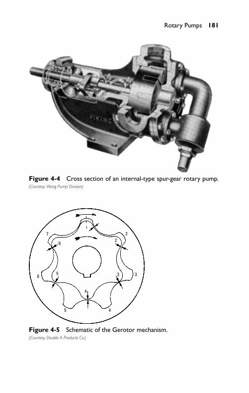
P1: FCH
GB098-04 GB098-Miller September 13, 2004 14:26 Char Count= 0
Rotary Pumps 181
Figure 4-4 Cross section of an internal-type spur-gear rotary pump.(Courtesy Viking Pump Division)
7
62
2
3 3
4
45
56
Figure 4-5 Schematic of the Gerotor mechanism.(Courtesy Double A Products Co.)
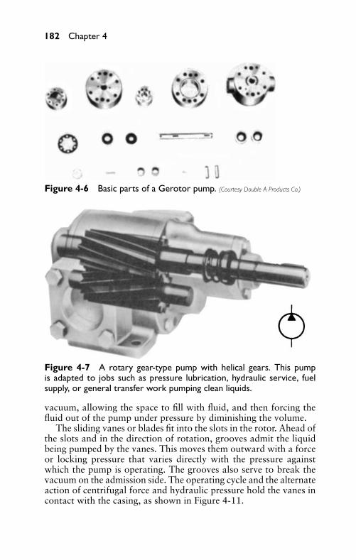
P1: FCH
GB098-04 GB098-Miller September 13, 2004 14:26 Char Count= 0
182 Chapter 4
Figure 4-6 Basic parts of a Gerotor pump. (Courtesy Double A Products Co.)
Figure 4-7 A rotary gear-type pump with helical gears. This pumpis adapted to jobs such as pressure lubrication, hydraulic service, fuelsupply, or general transfer work pumping clean liquids.
vacuum, allowing the space to fill with fluid, and then forcing thefluid out of the pump under pressure by diminishing the volume.
The sliding vanes or blades fit into the slots in the rotor. Ahead ofthe slots and in the direction of rotation, grooves admit the liquidbeing pumped by the vanes. This moves them outward with a forceor locking pressure that varies directly with the pressure againstwhich the pump is operating. The grooves also serve to break thevacuum on the admission side. The operating cycle and the alternateaction of centrifugal force and hydraulic pressure hold the vanes incontact with the casing, as shown in Figure 4-11.
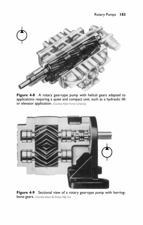
P1: FCH
GB098-04 GB098-Miller September 13, 2004 14:26 Char Count= 0
Rotary Pumps 183
Figure 4-8 A rotary gear-type pump with helical gears adapted toapplications requiring a quiet and compact unit, such as a hydraulic liftor elevator application. (Courtesy Roper Pump Company)
Figure 4-9 Sectional view of a rotary gear-type pump with herring-bone gears. (Courtesy Brown & Sharpe Mfg. Co.)
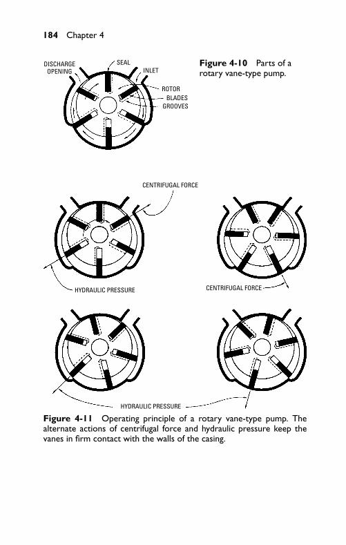
P1: FCH
GB098-04 GB098-Miller September 13, 2004 14:26 Char Count= 0
184 Chapter 4
SEALINLET
ROTORBLADES
GROOVES
DISCHARGEOPENING
Figure 4-10 Parts of arotary vane-type pump.
CENTRIFUGAL FORCE
HYDRAULIC PRESSURE
HYDRAULIC PRESSURE
CENTRIFUGAL FORCE
Figure 4-11 Operating principle of a rotary vane-type pump. Thealternate actions of centrifugal force and hydraulic pressure keep thevanes in firm contact with the walls of the casing.
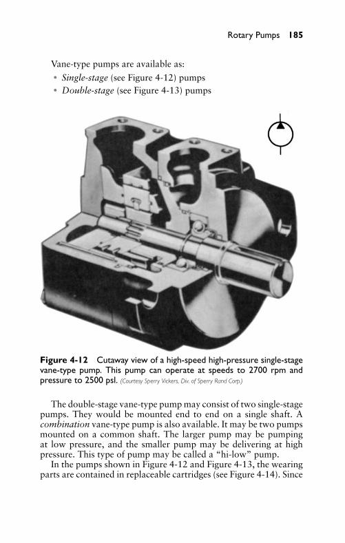
P1: FCH
GB098-04 GB098-Miller September 13, 2004 14:26 Char Count= 0
Rotary Pumps 185
Vane-type pumps are available as:� Single-stage (see Figure 4-12) pumps� Double-stage (see Figure 4-13) pumps
Figure 4-12 Cutaway view of a high-speed high-pressure single-stagevane-type pump. This pump can operate at speeds to 2700 rpm andpressure to 2500 psl. (Courtesy Sperry Vickers, Div. of Sperry Rand Corp.)
The double-stage vane-type pump may consist of two single-stagepumps. They would be mounted end to end on a single shaft. Acombination vane-type pump is also available. It may be two pumpsmounted on a common shaft. The larger pump may be pumpingat low pressure, and the smaller pump may be delivering at highpressure. This type of pump may be called a “hi-low” pump.
In the pumps shown in Figure 4-12 and Figure 4-13, the wearingparts are contained in replaceable cartridges (see Figure 4-14). Since
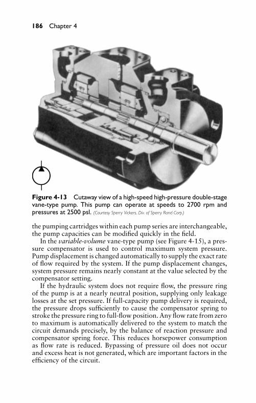
P1: FCH
GB098-04 GB098-Miller September 13, 2004 14:26 Char Count= 0
186 Chapter 4
Figure 4-13 Cutaway view of a high-speed high-pressure double-stagevane-type pump. This pump can operate at speeds to 2700 rpm andpressures at 2500 psl. (Courtesy Sperry Vickers, Div. of Sperry Rand Corp.)
the pumping cartridges within each pump series are interchangeable,the pump capacities can be modified quickly in the field.
In the variable-volume vane-type pump (see Figure 4-15), a pres-sure compensator is used to control maximum system pressure.Pump displacement is changed automatically to supply the exact rateof flow required by the system. If the pump displacement changes,system pressure remains nearly constant at the value selected by thecompensator setting.
If the hydraulic system does not require flow, the pressure ringof the pump is at a nearly neutral position, supplying only leakagelosses at the set pressure. If full-capacity pump delivery is required,the pressure drops sufficiently to cause the compensator spring tostroke the pressure ring to full-flow position. Any flow rate from zeroto maximum is automatically delivered to the system to match thecircuit demands precisely, by the balance of reaction pressure andcompensator spring force. This reduces horsepower consumptionas flow rate is reduced. Bypassing of pressure oil does not occurand excess heat is not generated, which are important factors in theefficiency of the circuit.
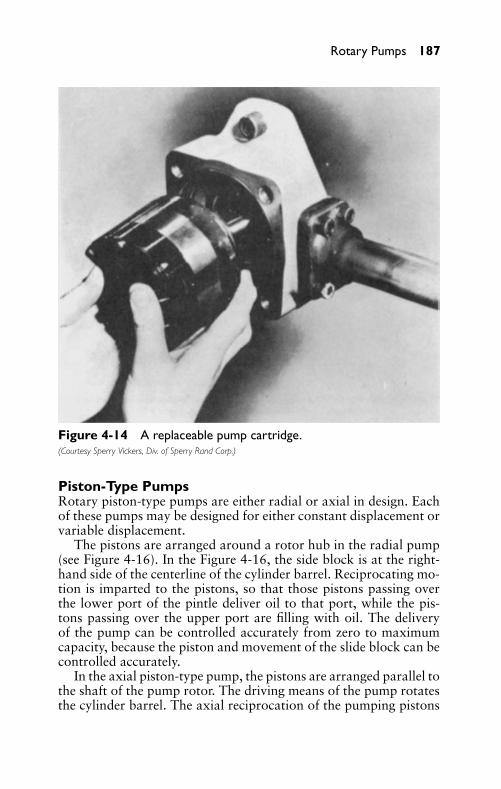
P1: FCH
GB098-04 GB098-Miller September 13, 2004 14:26 Char Count= 0
Rotary Pumps 187
Figure 4-14 A replaceable pump cartridge.(Courtesy Sperry Vickers, Div. of Sperry Rand Corp.)
Piston-Type PumpsRotary piston-type pumps are either radial or axial in design. Eachof these pumps may be designed for either constant displacement orvariable displacement.
The pistons are arranged around a rotor hub in the radial pump(see Figure 4-16). In the Figure 4-16, the side block is at the right-hand side of the centerline of the cylinder barrel. Reciprocating mo-tion is imparted to the pistons, so that those pistons passing overthe lower port of the pintle deliver oil to that port, while the pis-tons passing over the upper port are filling with oil. The deliveryof the pump can be controlled accurately from zero to maximumcapacity, because the piston and movement of the slide block can becontrolled accurately.
In the axial piston-type pump, the pistons are arranged parallel tothe shaft of the pump rotor. The driving means of the pump rotatesthe cylinder barrel. The axial reciprocation of the pumping pistons
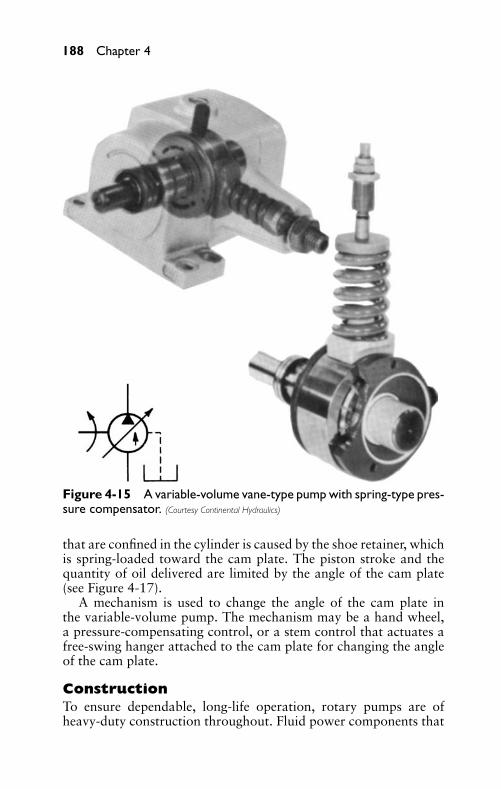
P1: FCH
GB098-04 GB098-Miller September 13, 2004 14:26 Char Count= 0
188 Chapter 4
Figure 4-15 A variable-volume vane-type pump with spring-type pres-sure compensator. (Courtesy Continental Hydraulics)
that are confined in the cylinder is caused by the shoe retainer, whichis spring-loaded toward the cam plate. The piston stroke and thequantity of oil delivered are limited by the angle of the cam plate(see Figure 4-17).
A mechanism is used to change the angle of the cam plate inthe variable-volume pump. The mechanism may be a hand wheel,a pressure-compensating control, or a stem control that actuates afree-swing hanger attached to the cam plate for changing the angleof the cam plate.
ConstructionTo ensure dependable, long-life operation, rotary pumps are ofheavy-duty construction throughout. Fluid power components that
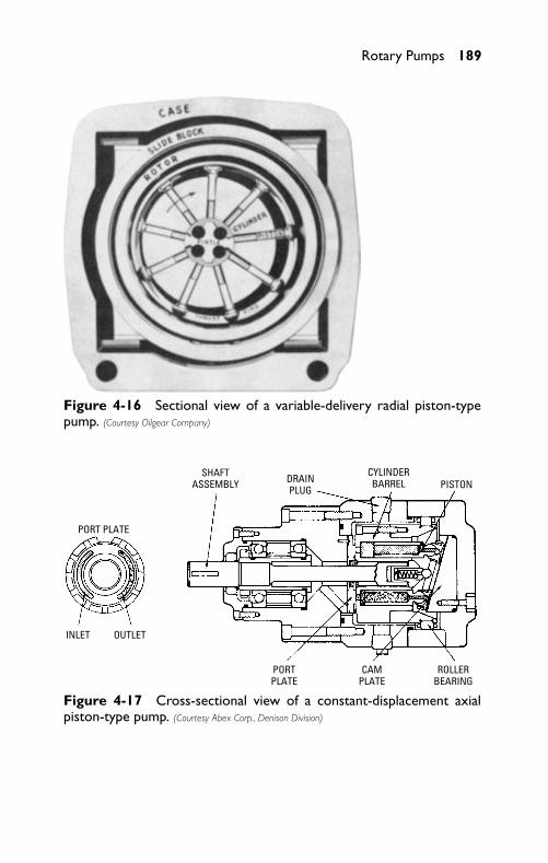
P1: FCH
GB098-04 GB098-Miller September 13, 2004 14:26 Char Count= 0
Rotary Pumps 189
Figure 4-16 Sectional view of a variable-delivery radial piston-typepump. (Courtesy Oilgear Company)
INLET
SHAFTASSEMBLY DRAIN
PLUG
CYLINDERBARREL PISTON
PORTPLATE
PORT PLATE
CAMPLATE
ROLLERBEARING
OUTLET
Figure 4-17 Cross-sectional view of a constant-displacement axialpiston-type pump. (Courtesy Abex Corp., Denison Division)
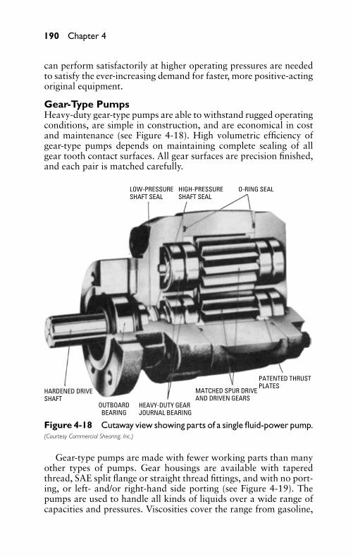
P1: FCH
GB098-04 GB098-Miller September 13, 2004 14:26 Char Count= 0
190 Chapter 4
can perform satisfactorily at higher operating pressures are neededto satisfy the ever-increasing demand for faster, more positive-actingoriginal equipment.
Gear-Type PumpsHeavy-duty gear-type pumps are able to withstand rugged operatingconditions, are simple in construction, and are economical in costand maintenance (see Figure 4-18). High volumetric efficiency ofgear-type pumps depends on maintaining complete sealing of allgear tooth contact surfaces. All gear surfaces are precision finished,and each pair is matched carefully.
LOW-PRESSURESHAFT SEAL
OUTBOARDBEARING
HIGH-PRESSURESHAFT SEAL
O-RING SEAL
HARDENED DRIVESHAFT
HEAVY-DUTY GEARJOURNAL BEARING
MATCHED SPUR DRIVEAND DRIVEN GEARS
PATENTED THRUSTPLATES
Figure 4-18 Cutaway view showing parts of a single fluid-power pump.(Courtesy Commercial Shearing, Inc.)
Gear-type pumps are made with fewer working parts than manyother types of pumps. Gear housings are available with taperedthread, SAE split flange or straight thread fittings, and with no port-ing, or left- and/or right-hand side porting (see Figure 4-19). Thepumps are used to handle all kinds of liquids over a wide range ofcapacities and pressures. Viscosities cover the range from gasoline,
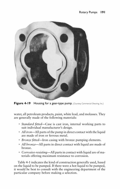
P1: FCH
GB098-04 GB098-Miller September 13, 2004 14:26 Char Count= 0
Rotary Pumps 191
Figure 4-19 Housing for a gear-type pump. (Courtesy Commercial Shearing, Inc.)
water, all petroleum products, paint, white lead, and molasses. Theyare generally made of the following materials:
� Standard fitted—Case is cast iron, internal working parts tosuit individual manufacturer’s design.
� All iron—All parts of the pump in direct contact with the liquidare made of iron or ferrous metal.
� Bronze fitted—Iron casing with bronze pumping elements.� All bronze—All parts in direct contact with liquid are made of
bronze.� Corrosive-resisting—All parts in contact with liquid are of ma-
terials offering maximum resistance to corrosion.
Table 4-1 indicates the kind of construction generally used, basedon the liquid to be pumped. If there were a hot liquid to be pumped,it would be best to consult with the engineering department of theparticular company before making a selection.
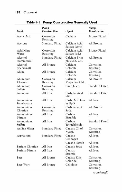
P1: FCH
GB098-04 GB098-Miller September 13, 2004 14:26 Char Count= 0
192 Chapter 4
Table 4-1 Pump Construction Generally Used
Pump PumpLiquid Construction Liquid Construction
Acetic Acid CorrosionResisting
Cachaza Bronze Fitted
Acetone Standard Fitted Calcium AcidSulfate (conc.)
All Bronze
Acid MineWater
CorrosionResisting
Calcium AcidSulfate (dil.)
Bronze Fitted
Alcohol(commercial)
Standard Fitted Calcium Brineplus Sod. Chl.
All Bronze
Alcohol(medicinal)
All Bronze CalciumChlorate
CorrosionResisting
Alum All Bronze CalciumChloride
CorrosionResisting
AluminumChloride
CorrosionResisting
CalciumMagn. So. Chl.
All Bronze
AluminumSulfate
CorrosionResisting
Cane Juice Standard Fitted
Ammonia All Iron Carbolic Acid(dil.)
Standard Fitted
AmmoniumBicarbonate
All Iron Carb. Acid Gasin H2O
All Iron
AmmoniumChloride
CorrosionResisting
Carbonate ofSoda
All Bronze
AmmoniumNitrate
All Iron CarbonBisulfide
All Iron
AmmoniumSulfate
All Iron CarbonTetrachloride
Standard Fitted
Aniline Water Standard Fitted Caustic Cl. ofMagn.
CorrosionResisting
Asphaltum Standard Fitted CausticCyanogen
All Iron
Caustic Potash All IronBarium Chloride All Iron Caustic Soda All IronBarium Nitrate All Iron Caustic
StrontiaAll Iron
Beer All Bronze Caustic ZincChloride
CorrosionResisting
Beer Wort All Bronze Cellulose CorrosionResisting
(continued )
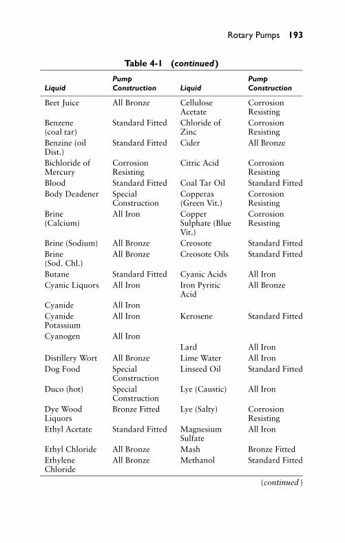
P1: FCH
GB098-04 GB098-Miller September 13, 2004 14:26 Char Count= 0
Rotary Pumps 193
Table 4-1 (continued)
Pump PumpLiquid Construction Liquid Construction
Beet Juice All Bronze CelluloseAcetate
CorrosionResisting
Benzene(coal tar)
Standard Fitted Chloride ofZinc
CorrosionResisting
Benzine (oilDist.)
Standard Fitted Cider All Bronze
Bichloride ofMercury
CorrosionResisting
Citric Acid CorrosionResisting
Blood Standard Fitted Coal Tar Oil Standard FittedBody Deadener Special
ConstructionCopperas(Green Vit.)
CorrosionResisting
Brine(Calcium)
All Iron CopperSulphate (BlueVit.)
CorrosionResisting
Brine (Sodium) All Bronze Creosote Standard FittedBrine(Sod. Chl.)
All Bronze Creosote Oils Standard Fitted
Butane Standard Fitted Cyanic Acids All IronCyanic Liquors All Iron Iron Pyritic
AcidAll Bronze
Cyanide All IronCyanidePotassium
All Iron Kerosene Standard Fitted
Cyanogen All IronLard All Iron
Distillery Wort All Bronze Lime Water All IronDog Food Special
ConstructionLinseed Oil Standard Fitted
Duco (hot) SpecialConstruction
Lye (Caustic) All Iron
Dye WoodLiquors
Bronze Fitted Lye (Salty) CorrosionResisting
Ethyl Acetate Standard Fitted MagnesiumSulfate
All Iron
Ethyl Chloride All Bronze Mash Bronze FittedEthyleneChloride
All Bronze Methanol Standard Fitted
(continued )
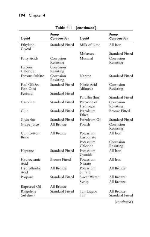
P1: FCH
GB098-04 GB098-Miller September 13, 2004 14:26 Char Count= 0
194 Chapter 4
Table 4-1 (continued)
Pump PumpLiquid Construction Liquid Construction
EthyleneGlycol
Standard Fitted Milk of Lime All Iron
Molasses Standard FittedFatty Acids Corrosion
ResistingMustard Corrosion
ResistingFerrousChloride
CorrosionResisting
Ferrous Sulfate CorrosionResisting
Naptha Standard Fitted
Fuel Oil(SeePetr. Oils)
Standard Fitted Nitric Acid(diluted)
CorrosionResisting
Furfural Standard FittedParaffin (hot) Standard Fitted
Gasoline Standard Fitted Peroxide ofHydrogen
CorrosionResisting
Glue Standard Fitted PetroleumEther
Bronze Fitted
Glycerine Standard Fitted Petroleum Oil Standard FittedGrape Juice All Bronze Potash Corrosion
ResistingGun CottonBrine
All Bronze PotassiumCarbonate
All Iron
PotassiumChloride
CorrosionResisting
Heptane Standard Fitted PotassiumCyanide
All Iron
HydrocyanicAcid
Bronze Fitted PotassiumNitrate
All Iron
HydroflusilicAcid
All Bronze PotassiumSulfate
All Bronze
Propane Standard Fitted Sweet Water All BronzeSyrup All Bronze
Rapeseed Oil All BronzeRhigolene(oil dust)
Standard Fitted Tan Liquor All BronzeTar Standard Fitted
(continued )
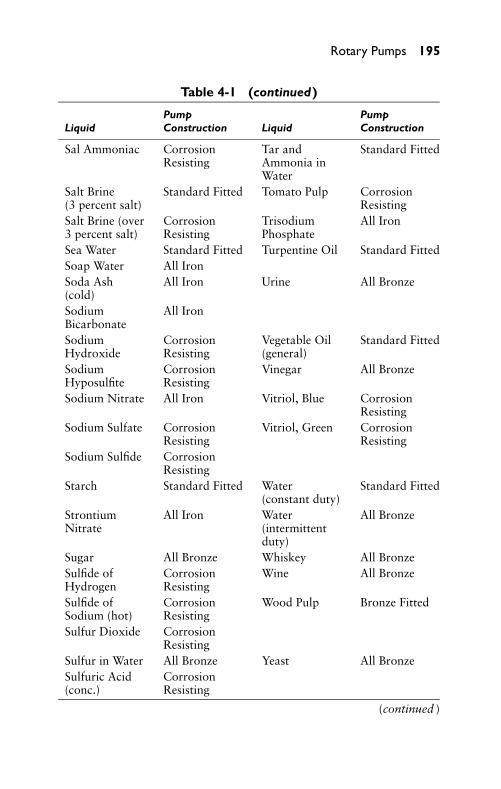
P1: FCH
GB098-04 GB098-Miller September 13, 2004 14:26 Char Count= 0
Rotary Pumps 195
Table 4-1 (continued)
Pump PumpLiquid Construction Liquid Construction
Sal Ammoniac CorrosionResisting
Tar andAmmonia inWater
Standard Fitted
Salt Brine(3 percent salt)
Standard Fitted Tomato Pulp CorrosionResisting
Salt Brine (over3 percent salt)
CorrosionResisting
TrisodiumPhosphate
All Iron
Sea Water Standard Fitted Turpentine Oil Standard FittedSoap Water All IronSoda Ash(cold)
All Iron Urine All Bronze
SodiumBicarbonate
All Iron
SodiumHydroxide
CorrosionResisting
Vegetable Oil(general)
Standard Fitted
SodiumHyposulfite
CorrosionResisting
Vinegar All Bronze
Sodium Nitrate All Iron Vitriol, Blue CorrosionResisting
Sodium Sulfate CorrosionResisting
Vitriol, Green CorrosionResisting
Sodium Sulfide CorrosionResisting
Starch Standard Fitted Water(constant duty)
Standard Fitted
StrontiumNitrate
All Iron Water(intermittentduty)
All Bronze
Sugar All Bronze Whiskey All BronzeSulfide ofHydrogen
CorrosionResisting
Wine All Bronze
Sulfide ofSodium (hot)
CorrosionResisting
Wood Pulp Bronze Fitted
Sulfur Dioxide CorrosionResisting
Sulfur in Water All Bronze Yeast All BronzeSulfuric Acid(conc.)
CorrosionResisting
(continued )
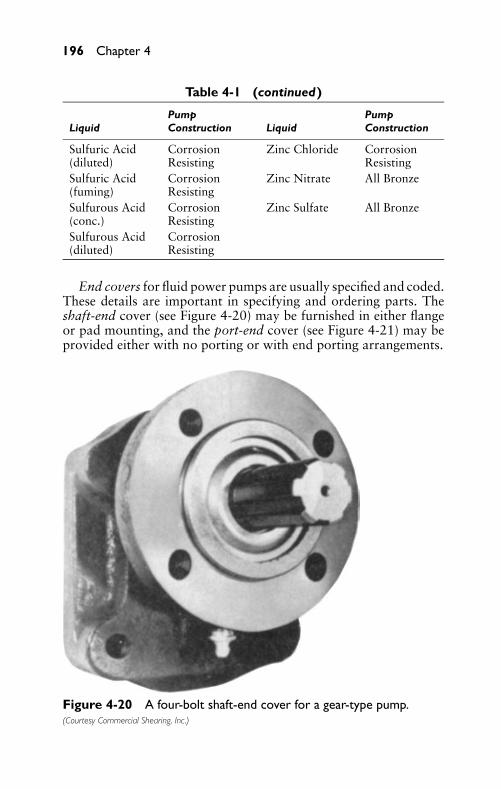
P1: FCH
GB098-04 GB098-Miller September 13, 2004 14:26 Char Count= 0
196 Chapter 4
Table 4-1 (continued)
Pump PumpLiquid Construction Liquid Construction
Sulfuric Acid(diluted)
CorrosionResisting
Zinc Chloride CorrosionResisting
Sulfuric Acid(fuming)
CorrosionResisting
Zinc Nitrate All Bronze
Sulfurous Acid(conc.)
CorrosionResisting
Zinc Sulfate All Bronze
Sulfurous Acid(diluted)
CorrosionResisting
End covers for fluid power pumps are usually specified and coded.These details are important in specifying and ordering parts. Theshaft-end cover (see Figure 4-20) may be furnished in either flangeor pad mounting, and the port-end cover (see Figure 4-21) may beprovided either with no porting or with end porting arrangements.
Figure 4-20 A four-bolt shaft-end cover for a gear-type pump.(Courtesy Commercial Shearing, Inc.)
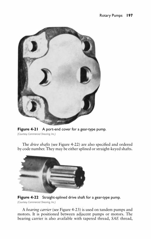
P1: FCH
GB098-04 GB098-Miller September 13, 2004 14:26 Char Count= 0
Rotary Pumps 197
Figure 4-21 A port-end cover for a gear-type pump.(Courtesy Commercial Shearing, Inc.)
The drive shafts (see Figure 4-22) are also specified and orderedby code number. They may be either splined or straight-keyed shafts.
Figure 4-22 Straight-splined drive shaft for a gear-type pump.(Courtesy Commercial Shearing, Inc.)
A bearing carrier (see Figure 4-23) is used on tandem pumps andmotors. It is positioned between adjacent pumps or motors. Thebearing carrier is also available with tapered thread, SAE thread,
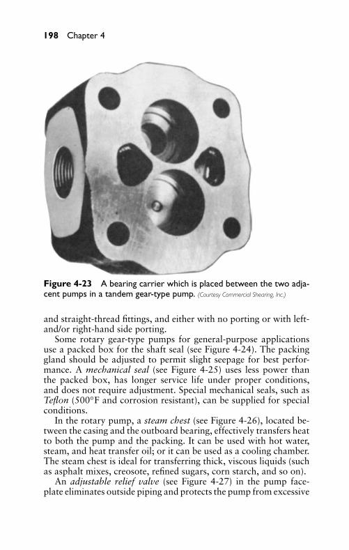
P1: FCH
GB098-04 GB098-Miller September 13, 2004 14:26 Char Count= 0
198 Chapter 4
Figure 4-23 A bearing carrier which is placed between the two adja-cent pumps in a tandem gear-type pump. (Courtesy Commercial Shearing, Inc.)
and straight-thread fittings, and either with no porting or with left-and/or right-hand side porting.
Some rotary gear-type pumps for general-purpose applicationsuse a packed box for the shaft seal (see Figure 4-24). The packinggland should be adjusted to permit slight seepage for best perfor-mance. A mechanical seal (see Figure 4-25) uses less power thanthe packed box, has longer service life under proper conditions,and does not require adjustment. Special mechanical seals, such asTeflon (500◦F and corrosion resistant), can be supplied for specialconditions.
In the rotary pump, a steam chest (see Figure 4-26), located be-tween the casing and the outboard bearing, effectively transfers heatto both the pump and the packing. It can be used with hot water,steam, and heat transfer oil; or it can be used as a cooling chamber.The steam chest is ideal for transferring thick, viscous liquids (suchas asphalt mixes, creosote, refined sugars, corn starch, and so on).
An adjustable relief valve (see Figure 4-27) in the pump face-plate eliminates outside piping and protects the pump from excessive
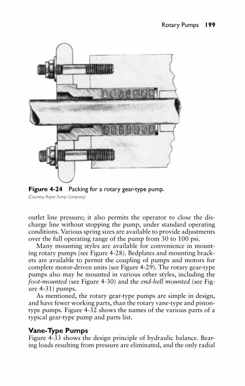
P1: FCH
GB098-04 GB098-Miller September 13, 2004 14:26 Char Count= 0
Rotary Pumps 199
Figure 4-24 Packing for a rotary gear-type pump.(Courtesy Roper Pump Company)
outlet line pressure; it also permits the operator to close the dis-charge line without stopping the pump, under standard operatingconditions. Various spring sizes are available to provide adjustmentsover the full operating range of the pump from 30 to 100 psi.
Many mounting styles are available for convenience in mount-ing rotary pumps (see Figure 4-28). Bedplates and mounting brack-ets are available to permit the coupling of pumps and motors forcomplete motor-driven units (see Figure 4-29). The rotary gear-typepumps also may be mounted in various other styles, including thefoot-mounted (see Figure 4-30) and the end-bell mounted (see Fig-ure 4-31) pumps.
As mentioned, the rotary gear-type pumps are simple in design,and have fewer working parts, than the rotary vane-type and piston-type pumps. Figure 4-32 shows the names of the various parts of atypical gear-type pump and parts list.
Vane-Type PumpsFigure 4-33 shows the design principle of hydraulic balance. Bear-ing loads resulting from pressure are eliminated, and the only radial
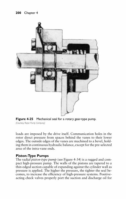
P1: FCH
GB098-04 GB098-Miller September 13, 2004 14:26 Char Count= 0
200 Chapter 4
Figure 4-25 Mechanical seal for a rotary gear-type pump.(Courtesy Roper Pump Company)
loads are imposed by the drive itself. Communication holes in therotor direct pressure from spaces behind the vanes to their loweredges. The outside edges of the vanes are machined to a bevel, hold-ing them in continuous hydraulic balance, except for the pre-selectedarea of the intra-vane ends.
Piston-Type PumpsThe radial piston-type pump (see Figure 4-34) is a rugged and com-pact high-pressure pump. The walls of the pistons are tapered to athin-edged section capable of expanding against the cylinder wall aspressure is applied. The higher the pressure, the tighter the seal be-comes, to increase the efficiency of high-pressure systems. Positive-acting check valves properly port the suction and discharge oil for
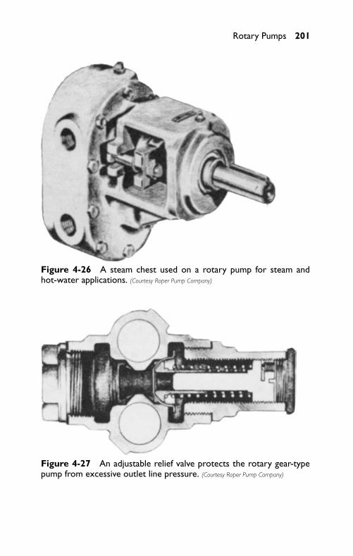
P1: FCH
GB098-04 GB098-Miller September 13, 2004 14:26 Char Count= 0
Rotary Pumps 201
Figure 4-26 A steam chest used on a rotary pump for steam andhot-water applications. (Courtesy Roper Pump Company)
Figure 4-27 An adjustable relief valve protects the rotary gear-typepump from excessive outlet line pressure. (Courtesy Roper Pump Company)
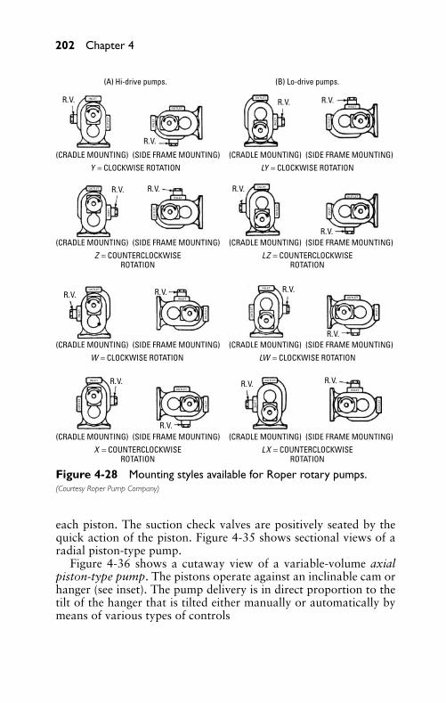
P1: FCH
GB098-04 GB098-Miller September 13, 2004 14:26 Char Count= 0
202 Chapter 4
(A) Hi-drive pumps. (B) Lo-drive pumps.
R.V. R.V. R.V.
R.V.
R.V. R.V. R.V.
R.V.
R.V.
R.V.
R.V. R.V.
R.V.
R.V.
R.V. R.V.
INLE
T
INLE
T
INLE
T
INLE
T
INLETOUTLET
OUTLET
INLE
T
OUTLET
INLE
T
OUTLET
OUTLET
INLE
T
OUTLET
INLE
T
OUTLET
OUTLET
OU
TLE
T
INLET
OU
TLE
T
INLET
INLET
OU
TLE
T
INLET
OU
TLE
T
INLET
OU
TLE
T
OU
TLE
T
INLET
OU
TLE
T
INLET
OU
TLE
T
(CRADLE MOUNTING) (SIDE FRAME MOUNTING) (CRADLE MOUNTING) (SIDE FRAME MOUNTING)
Y = CLOCKWISE ROTATION
(CRADLE MOUNTING) (SIDE FRAME MOUNTING)
Z = COUNTERCLOCKWISEROTATION
(CRADLE MOUNTING) (SIDE FRAME MOUNTING)
W = CLOCKWISE ROTATION
LY = CLOCKWISE ROTATION
(CRADLE MOUNTING) (SIDE FRAME MOUNTING)
LZ = COUNTERCLOCKWISEROTATION
(CRADLE MOUNTING) (SIDE FRAME MOUNTING)
X = COUNTERCLOCKWISEROTATION
(CRADLE MOUNTING) (SIDE FRAME MOUNTING)
LX = COUNTERCLOCKWISEROTATION
(CRADLE MOUNTING) (SIDE FRAME MOUNTING)
LW = CLOCKWISE ROTATION
Figure 4-28 Mounting styles available for Roper rotary pumps.(Courtesy Roper Pump Company)
each piston. The suction check valves are positively seated by thequick action of the piston. Figure 4-35 shows sectional views of aradial piston-type pump.
Figure 4-36 shows a cutaway view of a variable-volume axialpiston-type pump. The pistons operate against an inclinable cam orhanger (see inset). The pump delivery is in direct proportion to thetilt of the hanger that is tilted either manually or automatically bymeans of various types of controls
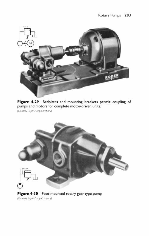
P1: FCH
GB098-04 GB098-Miller September 13, 2004 14:26 Char Count= 0
Rotary Pumps 203
M
Figure 4-29 Bedplates and mounting brackets permit coupling ofpumps and motors for complete motor-driven units.(Courtesy Roper Pump Company)
Figure 4-30 Foot-mounted rotary gear-type pump.(Courtesy Roper Pump Company)
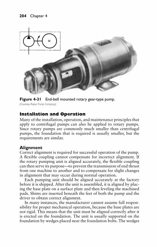
P1: FCH
GB098-04 GB098-Miller September 13, 2004 14:26 Char Count= 0
204 Chapter 4
M
Figure 4-31 End-bell mounted rotary gear-type pump.(Courtesy Roper Pump Company)
Installation and OperationMany of the installation, operation, and maintenance principles thatapply to centrifugal pumps can also be applied to rotary pumps.Since rotary pumps are commonly much smaller than centrifugalpumps, the foundation that is required is usually smaller, but therequirements are similar.
AlignmentCorrect alignment is required for successful operation of the pump.A flexible coupling cannot compensate for incorrect alignment. Ifthe rotary pumping unit is aligned accurately, the flexible couplingcan then serve its purpose—to prevent the transmission of end thrustfrom one machine to another and to compensate for slight changesin alignment that may occur during normal operation.
Each pumping unit should be aligned accurately at the factorybefore it is shipped. After the unit is assembled, it is aligned by plac-ing the base plate on a surface plate and then leveling the machinedpads. Shims are inserted beneath the feet of both the pump and thedriver to obtain correct alignment.
In many instances, the manufacturer cannot assume full respon-sibility for proper mechanical operation, because the base plates arenot rigid. This means that the unit must be aligned correctly after itis erected on the foundation. The unit is usually supported on thefoundation by wedges placed near the foundation bolts. The wedges
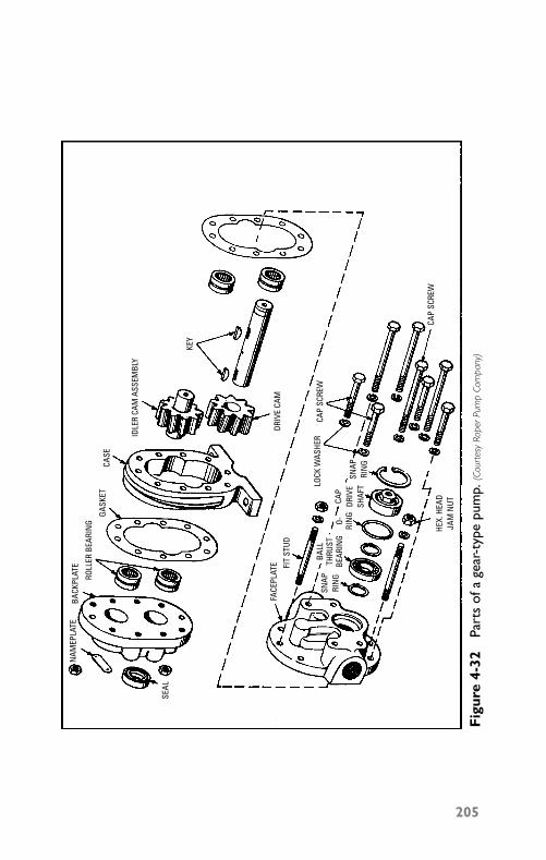
P1: FCH
GB098-04 GB098-Miller September 13, 2004 14:26 Char Count= 0
BACK
PLAT
E
ROLL
ER B
EARI
NG
GASK
ETCA
SE
IDLE
R CA
M A
SSEM
BLY
NAM
EPLA
TE
SEAL
DRIV
E CA
MFA
CEPL
ATE FI
T ST
UD
LOCK
WAS
HER
CAP
SCRE
W
CAP
SCRE
W
SNAP
RIN
G
CAP
DRIV
ESH
AFT
HEX.
HEA
DJA
M N
UT
SNAP
RIN
G
BALL
THRU
STBE
ARIN
GO- RIN
G
KEY
Fig
ure
4-32
Part
sof
age
ar-t
ype
pum
p.(C
ourt
esy
Rope
rPum
pCo
mpa
ny)
205
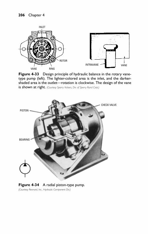
P1: FCH
GB098-04 GB098-Miller September 13, 2004 14:26 Char Count= 0
206 Chapter 4
INLET
VANE RING
ROTORINTRAVANE VANE
Figure 4-33 Design principle of hydraulic balance in the rotary vane-type pump (left). The lighter-colored area is the inlet, and the darker-shaded area is the outlet—rotation is clockwise. The design of the vaneis shown at right. (Courtesy Sperry Vickers, Div. of Sperry Rand Corp.)
PISTON
BEARING
CHECK VALVE
Figure 4-34 A radial piston-type pump.(Courtesy Rexnard, Inc., Hydraulic Component Div.)

P1: FCH
GB098-04 GB098-Miller September 13, 2004 14:26 Char Count= 0
Rotary Pumps 207
IN
OUT
Figure 4-35 Sectional views of a radial piston-type pump.(Courtesy Rexnard, Inc., Hydraulic Component Div.)
Figure 4-36 Cutaway view of a variable-volume axial piston-typepump (left) and Inclinable cam or hanger (right) that is tilted to con-trol pump’s delivery. (Courtesy Roper Pump Company)
underneath the base plate are adjusted, until a spirit level placed onthe pads indicates that the pump shaft is level.
The alignment should be checked and corrected to align the cou-pling half of the driver with the coupling half of the pump. Theshafts can be aligned by means of a straightedge and thickness gage(see Figure 4-37). The clearances between the coupling halves shouldbe set so that they cannot strike, rub, or exert end thrust on eitherthe pump or the driver.
Before placing the unit in operation, oil should be added to thecoupling. The alignment should be checked again after the piping to
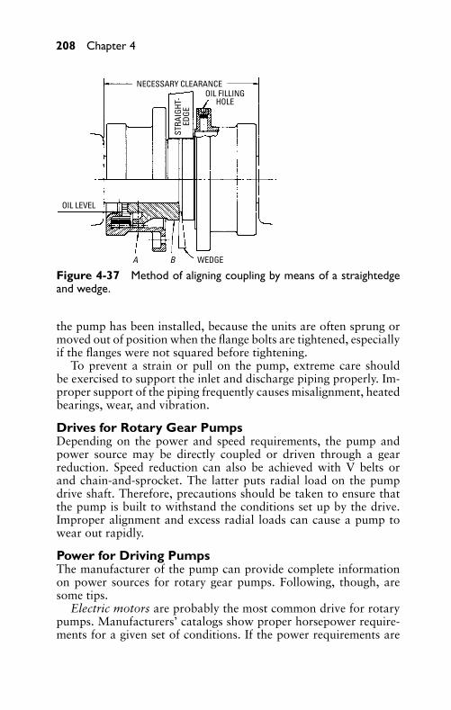
P1: FCH
GB098-04 GB098-Miller September 13, 2004 14:26 Char Count= 0
208 Chapter 4
NECESSARY CLEARANCEOIL FILLING
HOLE
OIL LEVEL
WEDGEA B
STRA
IGHT
-ED
GE
Figure 4-37 Method of aligning coupling by means of a straightedgeand wedge.
the pump has been installed, because the units are often sprung ormoved out of position when the flange bolts are tightened, especiallyif the flanges were not squared before tightening.
To prevent a strain or pull on the pump, extreme care shouldbe exercised to support the inlet and discharge piping properly. Im-proper support of the piping frequently causes misalignment, heatedbearings, wear, and vibration.
Drives for Rotary Gear PumpsDepending on the power and speed requirements, the pump andpower source may be directly coupled or driven through a gearreduction. Speed reduction can also be achieved with V belts orand chain-and-sprocket. The latter puts radial load on the pumpdrive shaft. Therefore, precautions should be taken to ensure thatthe pump is built to withstand the conditions set up by the drive.Improper alignment and excess radial loads can cause a pump towear out rapidly.
Power for Driving PumpsThe manufacturer of the pump can provide complete informationon power sources for rotary gear pumps. Following, though, aresome tips.
Electric motors are probably the most common drive for rotarypumps. Manufacturers’ catalogs show proper horsepower require-ments for a given set of conditions. If the power requirements are
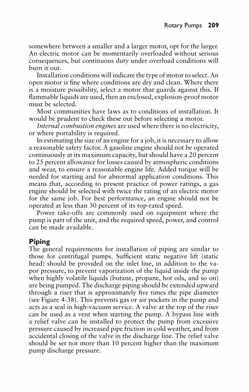
P1: FCH
GB098-04 GB098-Miller September 13, 2004 14:26 Char Count= 0
Rotary Pumps 209
somewhere between a smaller and a larger motor, opt for the larger.An electric motor can be momentarily overloaded without seriousconsequences, but continuous duty under overload conditions willburn it out.
Installation conditions will indicate the type of motor to select. Anopen motor is fine where conditions are dry and clean. Where thereis a moisture possibility, select a motor that guards against this. Ifflammable liquids are used, then an enclosed, explosion-proof motormust be selected.
Most communities have laws as to conditions of installation. Itwould be prudent to check these out before selecting a motor.
Internal combustion engines are used where there is no electricity,or where portability is required.
In estimating the size of an engine for a job, it is necessary to allowa reasonable safety factor. A gasoline engine should not be operatedcontinuously at its maximum capacity, but should have a 20 percentto 25 percent allowance for losses caused by atmospheric conditionsand wear, to ensure a reasonable engine life. Added torque will beneeded for starting and for abnormal application conditions. Thismeans that, according to present practice of power ratings, a gasengine should be selected with twice the rating of an electric motorfor the same job. For best performance, an engine should not beoperated at less than 30 percent of its top-rated speed.
Power take-offs are commonly used on equipment where thepump is part of the unit, and the required speed, power, and controlcan be made available.
PipingThe general requirements for installation of piping are similar tothose for centrifugal pumps. Sufficient static negative lift (statichead) should be provided on the inlet line, in addition to the va-por pressure, to prevent vaporization of the liquid inside the pumpwhen highly volatile liquids (butane, propane, hot oils, and so on)are being pumped. The discharge piping should be extended upwardthrough a riser that is approximately five times the pipe diameter(see Figure 4-38). This prevents gas or air pockets in the pump andacts as a seal in high-vacuum service. A valve at the top of the risercan be used as a vent when starting the pump. A bypass line witha relief valve can be installed to protect the pump from excessivepressure caused by increased pipe friction in cold weather, and fromaccidental closing of the valve in the discharge line. The relief valveshould be set not more than 10 percent higher than the maximumpump discharge pressure.
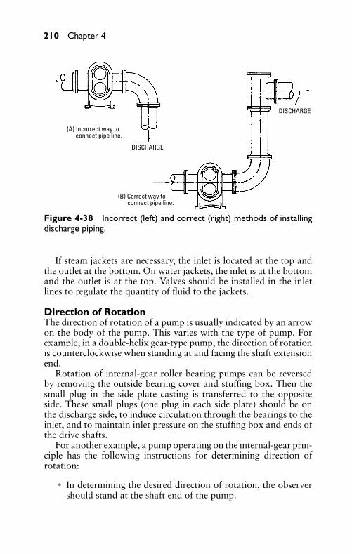
P1: FCH
GB098-04 GB098-Miller September 13, 2004 14:26 Char Count= 0
210 Chapter 4
(A) Incorrect way to connect pipe line.
(B) Correct way to connect pipe line.
DISCHARGE
DISCHARGE
Figure 4-38 Incorrect (left) and correct (right) methods of installingdischarge piping.
If steam jackets are necessary, the inlet is located at the top andthe outlet at the bottom. On water jackets, the inlet is at the bottomand the outlet is at the top. Valves should be installed in the inletlines to regulate the quantity of fluid to the jackets.
Direction of RotationThe direction of rotation of a pump is usually indicated by an arrowon the body of the pump. This varies with the type of pump. Forexample, in a double-helix gear-type pump, the direction of rotationis counterclockwise when standing at and facing the shaft extensionend.
Rotation of internal-gear roller bearing pumps can be reversedby removing the outside bearing cover and stuffing box. Then thesmall plug in the side plate casting is transferred to the oppositeside. These small plugs (one plug in each side plate) should be onthe discharge side, to induce circulation through the bearings to theinlet, and to maintain inlet pressure on the stuffing box and ends ofthe drive shafts.
For another example, a pump operating on the internal-gear prin-ciple has the following instructions for determining direction ofrotation:
� In determining the desired direction of rotation, the observershould stand at the shaft end of the pump.
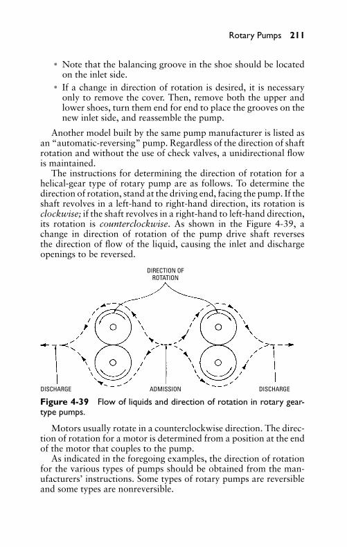
P1: FCH
GB098-04 GB098-Miller September 13, 2004 14:26 Char Count= 0
Rotary Pumps 211
� Note that the balancing groove in the shoe should be locatedon the inlet side.
� If a change in direction of rotation is desired, it is necessaryonly to remove the cover. Then, remove both the upper andlower shoes, turn them end for end to place the grooves on thenew inlet side, and reassemble the pump.
Another model built by the same pump manufacturer is listed asan “automatic-reversing” pump. Regardless of the direction of shaftrotation and without the use of check valves, a unidirectional flowis maintained.
The instructions for determining the direction of rotation for ahelical-gear type of rotary pump are as follows. To determine thedirection of rotation, stand at the driving end, facing the pump. If theshaft revolves in a left-hand to right-hand direction, its rotation isclockwise; if the shaft revolves in a right-hand to left-hand direction,its rotation is counterclockwise. As shown in the Figure 4-39, achange in direction of rotation of the pump drive shaft reversesthe direction of flow of the liquid, causing the inlet and dischargeopenings to be reversed.
DIRECTION OFROTATION
ADMISSION DISCHARGEDISCHARGE
Figure 4-39 Flow of liquids and direction of rotation in rotary gear-type pumps.
Motors usually rotate in a counterclockwise direction. The direc-tion of rotation for a motor is determined from a position at the endof the motor that couples to the pump.
As indicated in the foregoing examples, the direction of rotationfor the various types of pumps should be obtained from the man-ufacturers’ instructions. Some types of rotary pumps are reversibleand some types are nonreversible.
P1: FCH
GB098-04 GB098-Miller September 13, 2004 14:26 Char Count= 0
212 Chapter 4
Starting and Operating the PumpBefore starting the pump, it should be primed. Then, the primemover should be checked for proper direction of rotation. Pressureor vacuum should be checked on the inlet side, and pressure shouldbe checked on the outlet side, to determine whether they conformto specifications and whether the pump can deliver full capacitywithout overloading the driver.
Operation should be started at a reduced load, gradually increas-ing to maximum service conditions. Pumps with external bearingsmay require occasional lubrication or soft grease for the bearings.If grease fittings are not furnished on pumps with internal bearings,lubrication is not necessary.
Practical InstallationGear pumps are simple and rugged in construction. A minimumnumber of moving parts ensures longer service life and lower main-tenance cost. Their design criteria are for high flow at moderatepressures. Gear pumps are self-priming and excellent for viscousliquids. All fluids must be free of abrasives such as sand, silt, andwettable powders.
SuctionFor best performance, the pump should be installed as near the liquidsource as possible. Figure 4-40 shows proper piping arrangement ofgear pumps and the location of other equipment for safe operationof the unit. Excessive pipe lengths and elbows create fluid losses thatdetract from the overall efficiency of the pump. It is recommendedin good practice that the total suction lift (sum of static and dynamiclift) should not exceed 15 feet. Intake porting should never be re-duced for piping convenience. Reducing the porting on any givensize unit will starve the pump and cause cavitations which will resultin a form of internal erosion. Line strainers are recommended foruse on the suction side of installations (see Figure 4-41).
DischargeSince gear pumps are positive displacement, care must be taken withthe use of restrictive devices (such as gate valves) in the dischargeline for purpose of throttling. Accidental closing of the dischargeline can cause extreme overpressure, which may result in seriousdamage to the pump or motor. If the discharge line throttling isnecessary, selection of the pump with a built-in relief valve should beconsidered.
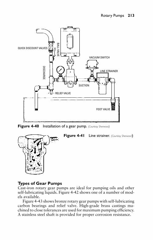
P1: FCH
GB098-04 GB098-Miller September 13, 2004 14:26 Char Count= 0
Rotary Pumps 213
QUICK DISCOUNT VALVES
DISCHARGE
BALL VALVE
VACUUM SWITCH
LINE STRAINER
SUCTION
RELIEF VALVE
FOOT VALVE
Figure 4-40 Installation of a gear pump. (Courtesy Sherwood)
Figure 4-41 Line strainer. (Courtesy Sherwood)
Types of Gear PumpsCast-iron rotary gear pumps are ideal for pumping oils and otherself-lubricating liquids. Figure 4-42 shows one of a number of mod-els available.
Figure 4-43 shows bronze rotary gear pumps with self-lubricatingcarbon bearings and relief valve. High-grade brass castings ma-chined to close tolerances are used for maximum pumping efficiency.A stainless steel shaft is provided for proper corrosion resistance.
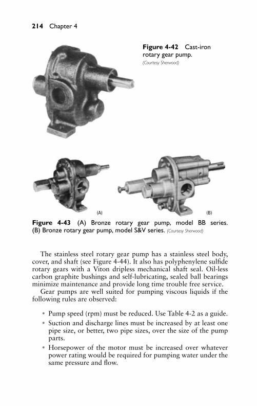
P1: FCH
GB098-04 GB098-Miller September 13, 2004 14:26 Char Count= 0
214 Chapter 4
Figure 4-42 Cast-ironrotary gear pump.(Courtesy Sherwood)
(B)(A)
Figure 4-43 (A) Bronze rotary gear pump, model BB series.(B) Bronze rotary gear pump, model S&V series. (Courtesy Sherwood)
The stainless steel rotary gear pump has a stainless steel body,cover, and shaft (see Figure 4-44). It also has polyphenylene sulfiderotary gears with a Viton dripless mechanical shaft seal. Oil-lesscarbon graphite bushings and self-lubricating, sealed ball bearingsminimize maintenance and provide long time trouble free service.
Gear pumps are well suited for pumping viscous liquids if thefollowing rules are observed:
� Pump speed (rpm) must be reduced. Use Table 4-2 as a guide.� Suction and discharge lines must be increased by at least one
pipe size, or better, two pipe sizes, over the size of the pumpparts.
� Horsepower of the motor must be increased over whateverpower rating would be required for pumping water under thesame pressure and flow.
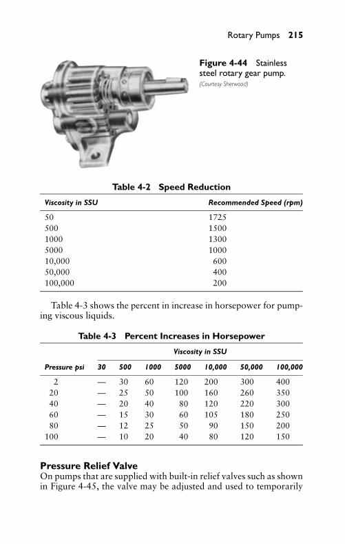
P1: FCH
GB098-04 GB098-Miller September 13, 2004 14:26 Char Count= 0
Rotary Pumps 215
Figure 4-44 Stainlesssteel rotary gear pump.(Courtesy Sherwood)
Table 4-2 Speed Reduction
Viscosity in SSU Recommended Speed (rpm)
50 1725500 15001000 13005000 100010,000 60050,000 400100,000 200
Table 4-3 shows the percent in increase in horsepower for pump-ing viscous liquids.
Table 4-3 Percent Increases in Horsepower
Viscosity in SSU
Pressure psi 30 500 1000 5000 10,000 50,000 100,000
2 — 30 60 120 200 300 40020 — 25 50 100 160 260 35040 — 20 40 80 120 220 30060 — 15 30 60 105 180 25080 — 12 25 50 90 150 200
100 — 10 20 40 80 120 150
Pressure Relief ValveOn pumps that are supplied with built-in relief valves such as shownin Figure 4-45, the valve may be adjusted and used to temporarily
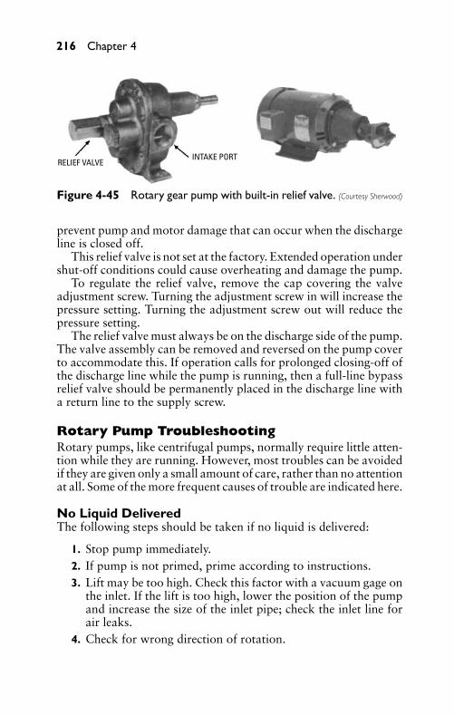
P1: FCH
GB098-04 GB098-Miller September 13, 2004 14:26 Char Count= 0
216 Chapter 4
RELIEF VALVEINTAKE PORT
Figure 4-45 Rotary gear pump with built-in relief valve. (Courtesy Sherwood)
prevent pump and motor damage that can occur when the dischargeline is closed off.
This relief valve is not set at the factory. Extended operation undershut-off conditions could cause overheating and damage the pump.
To regulate the relief valve, remove the cap covering the valveadjustment screw. Turning the adjustment screw in will increase thepressure setting. Turning the adjustment screw out will reduce thepressure setting.
The relief valve must always be on the discharge side of the pump.The valve assembly can be removed and reversed on the pump coverto accommodate this. If operation calls for prolonged closing-off ofthe discharge line while the pump is running, then a full-line bypassrelief valve should be permanently placed in the discharge line witha return line to the supply screw.
Rotary Pump TroubleshootingRotary pumps, like centrifugal pumps, normally require little atten-tion while they are running. However, most troubles can be avoidedif they are given only a small amount of care, rather than no attentionat all. Some of the more frequent causes of trouble are indicated here.
No Liquid DeliveredThe following steps should be taken if no liquid is delivered:
1. Stop pump immediately.2. If pump is not primed, prime according to instructions.3. Lift may be too high. Check this factor with a vacuum gage on
the inlet. If the lift is too high, lower the position of the pumpand increase the size of the inlet pipe; check the inlet line forair leaks.
4. Check for wrong direction of rotation.
P1: FCH
GB098-04 GB098-Miller September 13, 2004 14:26 Char Count= 0
Rotary Pumps 217
Insufficient Liquid DeliveredOne of the following causes may result in delivery of insufficientliquid:
� Air leak in the inlet line or through the stuffing box. Oil andtighten the stuffing-box gland. Paint the inlet pipe joints withshellac.
� Speed too slow. The rpm should be checked. The driver maybe overloaded, or the cause may be low voltage or low steampressure.
� Lift may be too high. Check with a vacuum gage. Small frac-tions in some liquids vaporize easily and occupy a portion ofthe pump displacement.
� Excess lift for hot liquids.� Pump may be worn.� Foot valve may not be deep enough (not required on many
pumps).� Foot valve may be either too small or obstructed.� Piping is improperly installed, permitting air or gas to pocket
inside the pump.� Mechanical defects, such as defective packing or damaged
pump.
Pump Delivers for a Short Period, Then QuitsThis problem may be a result of one of the following causes:
� Leak in the inlet.� End of the inlet valve is not deep enough.� Air or gas in the liquid.� Supply is exhausted.� Vaporization of the liquid in the inlet line. Check this with the
vacuum gage to be sure that the pressure in the pump is greaterthan the vapor pressure of the liquid.
� Air or gas pockets in the inlet line.� Pump is cut by presence of sand or other abrasives in the liquid.
Rapid WearSome of the causes of rapid wear in a pump are the following:
� Grit or dirt in the liquid that is being pumped. A fine-meshstrainer or filter can be installed in the inlet line.
P1: FCH
GB098-04 GB098-Miller September 13, 2004 14:26 Char Count= 0
218 Chapter 4
� Pipe strain on the pump casing causes the working parts tobind. The pipe connections can be released and the alignmentchecked to determine whether this factor is a cause of rapidwear.
� Pump operating against excessive pressure.� Corrosion roughens surfaces.� Pump runs dry or with insufficient liquid.
Pump Requires Too Much PowerToo much power required to operate the pump may be caused bythe following:
� Speed too fast.� Liquid either heavier or more viscous than water.� Mechanical defects, such as a bent shaft, binding of the rotat-
ing element, stuffing boxes too tight, misalignment caused byimproper connections to the pipelines, or installation on thefoundation in such a way that the base is sprung.
� Misalignment of the coupling (direct-connected units).
Noisy OperationThe causes of noisy operation may be the following:
� Insufficient supply, which may be because of liquid vaporizingin the pump. This may be corrected by lowering the pump andby increasing the size of the inlet pipe.
� Air leaks in the inlet pipe, causing a crackling noise in thepump.
� Air or gas pockets in the inlet.� A pump that is out of alignment, causing metallic contact be-
tween the rotors and the casing.� Operating against excessive pressure.� Coupling out of balance.
CalculationsIn nearly all installations, it is important to calculate the size ofpump, horsepower, lift, head, total load, and so on. This is impor-tant in determining whether the system is operating with maximumefficiency.
P1: FCH
GB098-04 GB098-Miller September 13, 2004 14:26 Char Count= 0
Rotary Pumps 219
Correct Size of PumpIt is always important to determine whether the pump is too largeor too small for the job—either before or after it has been installed.
ProblemIn a given installation, a pump is required that can fill an 8000-gallontank in two hours. What size pump is required?
SolutionSince the capacity of a pump is rated in gallons per minute (gpm),the 8000 gallons in two hours that is required can be reduced togpm as follows:
gpm = 80002 × 60
= 662/3, or approximately 70 gpm
If the rated capacity of a given pump indicates that the pumpcan deliver 70 gpm at 450 rpm, and since the capacity of a pumpis nearly proportional to its speed, the rpm required to deliver 662/3gallons of water per minute can be determined as follows:
required rpm = 450 × 662/3
70= 428.6 rpm
Therefore, if the pump is rated to deliver 70 gpm at 450 rpm, itshould be capable of delivering 662/3 gpm at 428.6 rpm, which iswithin the rated capacity of the pump.
Friction of Water in PipesThe values for loss of head caused by friction can be obtainedfrom Chapter 3. The values in Table 3-3 are based on 15-year-oldwrought-iron or cast-iron pipe when pumping clear soft water. Thefollowing coefficients can be used to determine the friction in pipesfor various lengths of service:
� New, smooth pipe—0.71� 10-year-old pipe—0.84� 15-year-old pipe—1.00� 20-year-old pipe—1.22
Friction Loss in Rubber HoseThe friction loss in smooth bore rubber hose is about the same ascorresponding sizes of steel pipe. Table 4-4 shows the loss in poundsper 100 feet of hose.

P1: FCH
GB098-04 GB098-Miller September 13, 2004 14:26 Char Count= 0
220 Chapter 4
Table 4-4 Loss in Pounds per 100 Feet ofSmooth Bore Rubber Hose
U.S. Gal.Per Min. Actual Inside Diameter in Inches
3/4 1 11/4 11/2 2 21/2 3 4
15 30.0 8.9 2.5 1.1 0.4 0.120 53.0 14.0 4.3 1.8 0.7 0.225 79.0 22.0 6.5 2.9 1.0 0.330 112.0 31.0 9.2 4.0 1.4 0.4 0.140 53.0 15.0 6.7 2.4 0.6 0.350 80.0 24.0 10.0 3.6 1.0 0.560 101.0 35.0 14.0 5.1 1.4 0.670 45.0 19.0 6.6 1.8 0.880 58.0 24.0 8.6 2.3 1.190 71.0 30.0 11.0 3.0 1.4 0.3
100 88.0 37.0 12.5 3.5 1.7 0.4125 132.0 55.0 20.0 5.3 2.5 0.6150 183.0 78.0 27.0 7.5 3.5 0.7175 100.0 37.0 10.0 4.6 1.1200 133.0 46.0 13.0 5.9 1.4250 70.0 19.0 9.1 2.1300 95.0 27.0 12.0 2.9350 126.0 36.0 17.0 4.0400 46.0 21.0 5.1500 70.0 32.0 7.4600 105.0 46.0 10.0700 148.0 62.0 13.0800 190.0 79.0 17.0900 97.0 22.0
1000 116.0 27.01250 170.0 43.01500 226.0 61.01750 80.02000 100.0
Data shown is for liquid having specific gravity of 1 and a viscosity of 30 SSU
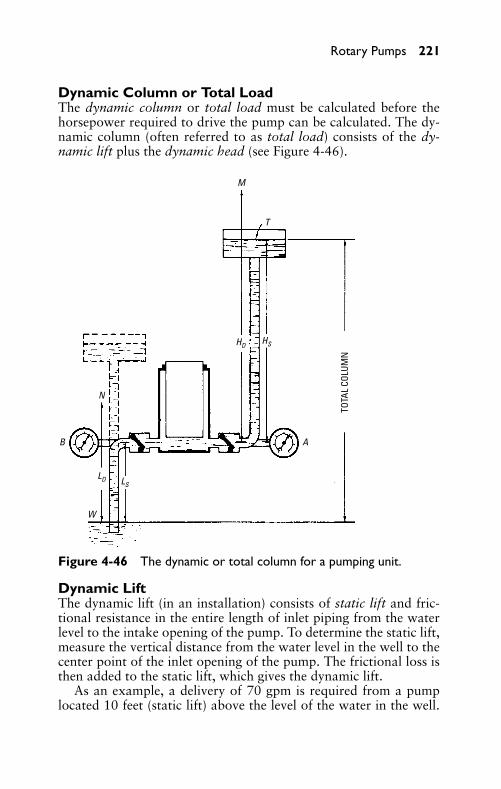
P1: FCH
GB098-04 GB098-Miller September 13, 2004 14:26 Char Count= 0
Rotary Pumps 221
Dynamic Column or Total LoadThe dynamic column or total load must be calculated before thehorsepower required to drive the pump can be calculated. The dy-namic column (often referred to as total load) consists of the dy-namic lift plus the dynamic head (see Figure 4-46).
TOTA
L CO
LUM
N
M
T
A
N
W
B
LD LS
HD HS
Figure 4-46 The dynamic or total column for a pumping unit.
Dynamic LiftThe dynamic lift (in an installation) consists of static lift and fric-tional resistance in the entire length of inlet piping from the waterlevel to the intake opening of the pump. To determine the static lift,measure the vertical distance from the water level in the well to thecenter point of the inlet opening of the pump. The frictional loss isthen added to the static lift, which gives the dynamic lift.
As an example, a delivery of 70 gpm is required from a pumplocated 10 feet (static lift) above the level of the water in the well.
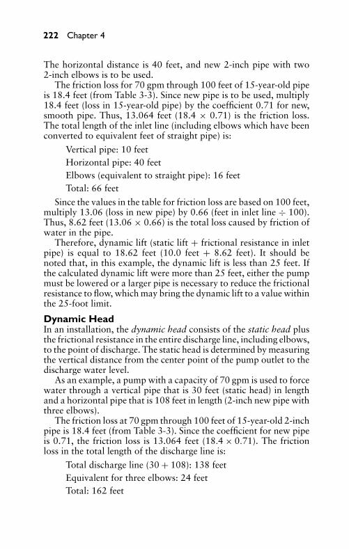
P1: FCH
GB098-04 GB098-Miller September 13, 2004 14:26 Char Count= 0
222 Chapter 4
The horizontal distance is 40 feet, and new 2-inch pipe with two2-inch elbows is to be used.
The friction loss for 70 gpm through 100 feet of 15-year-old pipeis 18.4 feet (from Table 3-3). Since new pipe is to be used, multiply18.4 feet (loss in 15-year-old pipe) by the coefficient 0.71 for new,smooth pipe. Thus, 13.064 feet (18.4 × 0.71) is the friction loss.The total length of the inlet line (including elbows which have beenconverted to equivalent feet of straight pipe) is:
Vertical pipe: 10 feetHorizontal pipe: 40 feetElbows (equivalent to straight pipe): 16 feetTotal: 66 feet
Since the values in the table for friction loss are based on 100 feet,multiply 13.06 (loss in new pipe) by 0.66 (feet in inlet line ÷ 100).Thus, 8.62 feet (13.06 × 0.66) is the total loss caused by friction ofwater in the pipe.
Therefore, dynamic lift (static lift + frictional resistance in inletpipe) is equal to 18.62 feet (10.0 feet + 8.62 feet). It should benoted that, in this example, the dynamic lift is less than 25 feet. Ifthe calculated dynamic lift were more than 25 feet, either the pumpmust be lowered or a larger pipe is necessary to reduce the frictionalresistance to flow, which may bring the dynamic lift to a value withinthe 25-foot limit.
Dynamic HeadIn an installation, the dynamic head consists of the static head plusthe frictional resistance in the entire discharge line, including elbows,to the point of discharge. The static head is determined by measuringthe vertical distance from the center point of the pump outlet to thedischarge water level.
As an example, a pump with a capacity of 70 gpm is used to forcewater through a vertical pipe that is 30 feet (static head) in lengthand a horizontal pipe that is 108 feet in length (2-inch new pipe withthree elbows).
The friction loss at 70 gpm through 100 feet of 15-year-old 2-inchpipe is 18.4 feet (from Table 3-3). Since the coefficient for new pipeis 0.71, the friction loss is 13.064 feet (18.4 × 0.71). The frictionloss in the total length of the discharge line is:
Total discharge line (30 + 108): 138 feetEquivalent for three elbows: 24 feetTotal: 162 feet
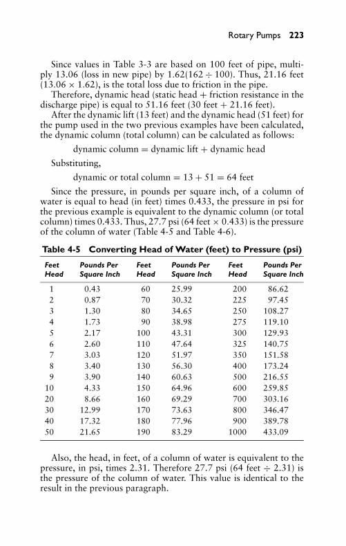
P1: FCH
GB098-04 GB098-Miller September 13, 2004 14:26 Char Count= 0
Rotary Pumps 223
Since values in Table 3-3 are based on 100 feet of pipe, multi-ply 13.06 (loss in new pipe) by 1.62(162 ÷ 100). Thus, 21.16 feet(13.06 × 1.62), is the total loss due to friction in the pipe.
Therefore, dynamic head (static head + friction resistance in thedischarge pipe) is equal to 51.16 feet (30 feet + 21.16 feet).
After the dynamic lift (13 feet) and the dynamic head (51 feet) forthe pump used in the two previous examples have been calculated,the dynamic column (total column) can be calculated as follows:
dynamic column = dynamic lift + dynamic head
Substituting,
dynamic or total column = 13 + 51 = 64 feet
Since the pressure, in pounds per square inch, of a column ofwater is equal to head (in feet) times 0.433, the pressure in psi forthe previous example is equivalent to the dynamic column (or totalcolumn) times 0.433. Thus, 27.7 psi (64 feet × 0.433) is the pressureof the column of water (Table 4-5 and Table 4-6).
Table 4-5 Converting Head of Water (feet) to Pressure (psi)
Feet Pounds Per Feet Pounds Per Feet Pounds PerHead Square Inch Head Square Inch Head Square Inch
1 0.43 60 25.99 200 86.622 0.87 70 30.32 225 97.453 1.30 80 34.65 250 108.274 1.73 90 38.98 275 119.105 2.17 100 43.31 300 129.936 2.60 110 47.64 325 140.757 3.03 120 51.97 350 151.588 3.40 130 56.30 400 173.249 3.90 140 60.63 500 216.55
10 4.33 150 64.96 600 259.8520 8.66 160 69.29 700 303.1630 12.99 170 73.63 800 346.4740 17.32 180 77.96 900 389.7850 21.65 190 83.29 1000 433.09
Also, the head, in feet, of a column of water is equivalent to thepressure, in psi, times 2.31. Therefore 27.7 psi (64 feet ÷ 2.31) isthe pressure of the column of water. This value is identical to theresult in the previous paragraph.
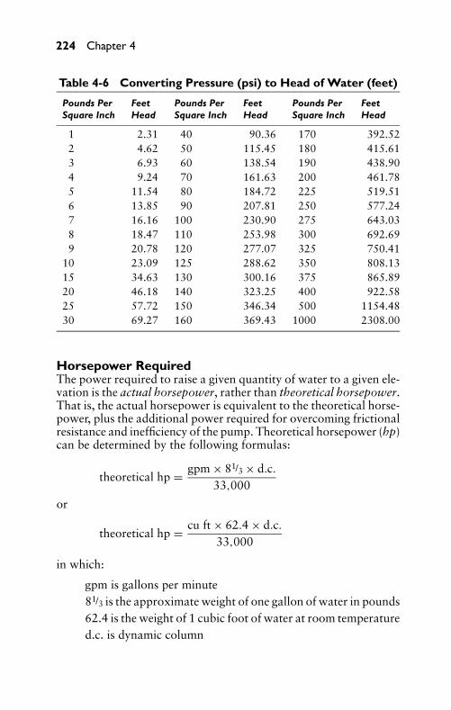
P1: FCH
GB098-04 GB098-Miller September 13, 2004 14:26 Char Count= 0
224 Chapter 4
Table 4-6 Converting Pressure (psi) to Head of Water (feet)
Pounds Per Feet Pounds Per Feet Pounds Per FeetSquare Inch Head Square Inch Head Square Inch Head
1 2.31 40 90.36 170 392.522 4.62 50 115.45 180 415.613 6.93 60 138.54 190 438.904 9.24 70 161.63 200 461.785 11.54 80 184.72 225 519.516 13.85 90 207.81 250 577.247 16.16 100 230.90 275 643.038 18.47 110 253.98 300 692.699 20.78 120 277.07 325 750.41
10 23.09 125 288.62 350 808.1315 34.63 130 300.16 375 865.8920 46.18 140 323.25 400 922.5825 57.72 150 346.34 500 1154.4830 69.27 160 369.43 1000 2308.00
Horsepower RequiredThe power required to raise a given quantity of water to a given ele-vation is the actual horsepower, rather than theoretical horsepower.That is, the actual horsepower is equivalent to the theoretical horse-power, plus the additional power required for overcoming frictionalresistance and inefficiency of the pump. Theoretical horsepower (hp)can be determined by the following formulas:
theoretical hp = gpm × 81/3 × d.c.33,000
or
theoretical hp = cu ft × 62.4 × d.c.33,000
in which:
gpm is gallons per minute81/3 is the approximate weight of one gallon of water in pounds62.4 is the weight of 1 cubic foot of water at room temperatured.c. is dynamic column
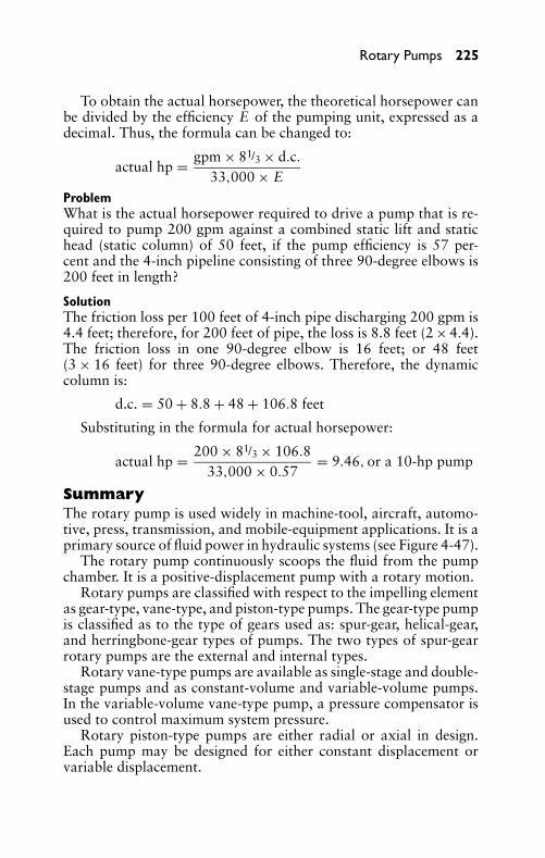
P1: FCH
GB098-04 GB098-Miller September 13, 2004 14:26 Char Count= 0
Rotary Pumps 225
To obtain the actual horsepower, the theoretical horsepower canbe divided by the efficiency E of the pumping unit, expressed as adecimal. Thus, the formula can be changed to:
actual hp = gpm × 81/3 × d.c.33,000 × E
ProblemWhat is the actual horsepower required to drive a pump that is re-quired to pump 200 gpm against a combined static lift and statichead (static column) of 50 feet, if the pump efficiency is 57 per-cent and the 4-inch pipeline consisting of three 90-degree elbows is200 feet in length?
SolutionThe friction loss per 100 feet of 4-inch pipe discharging 200 gpm is4.4 feet; therefore, for 200 feet of pipe, the loss is 8.8 feet (2 × 4.4).The friction loss in one 90-degree elbow is 16 feet; or 48 feet(3 × 16 feet) for three 90-degree elbows. Therefore, the dynamiccolumn is:
d.c. = 50 + 8.8 + 48 + 106.8 feet
Substituting in the formula for actual horsepower:
actual hp = 200 × 81/3 × 106.833,000 × 0.57
= 9.46, or a 10-hp pump
SummaryThe rotary pump is used widely in machine-tool, aircraft, automo-tive, press, transmission, and mobile-equipment applications. It is aprimary source of fluid power in hydraulic systems (see Figure 4-47).
The rotary pump continuously scoops the fluid from the pumpchamber. It is a positive-displacement pump with a rotary motion.
Rotary pumps are classified with respect to the impelling elementas gear-type, vane-type, and piston-type pumps. The gear-type pumpis classified as to the type of gears used as: spur-gear, helical-gear,and herringbone-gear types of pumps. The two types of spur-gearrotary pumps are the external and internal types.
Rotary vane-type pumps are available as single-stage and double-stage pumps and as constant-volume and variable-volume pumps.In the variable-volume vane-type pump, a pressure compensator isused to control maximum system pressure.
Rotary piston-type pumps are either radial or axial in design.Each pump may be designed for either constant displacement orvariable displacement.
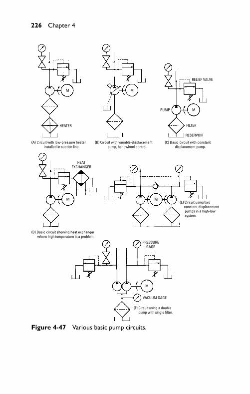
P1: FCH
GB098-04 GB098-Miller September 13, 2004 14:26 Char Count= 0
226 Chapter 4
M
M
M
M
M
HEATER
(A) Circuit with low-pressure heater installed in suction line.
(B) Circuit with variable-displacement pump, handwheel control.
M(E) Circuit using two constant-displacement pumps in a high-low system.
RELIEF VALVE
HEATEXCHANGER
PUMP
FILTER
RESERVOIR
PRESSUREGAGE
VACUUM GAGE
(C) Basic circuit with constant displacement pump.
(D) Basic circuit showing heat exchanger where high temperature is a problem.
(F) Circuit using a double pump with single filter.
Figure 4-47 Various basic pump circuits.
P1: FCH
GB098-04 GB098-Miller September 13, 2004 14:26 Char Count= 0
Rotary Pumps 227
Rotary pumps are of heavy-duty construction throughout. Thesepumps and components can perform satisfactorily at high operatingpressures.
The direction of rotation for a rotary pump is usually indicated byan arrow on the body of the pump. The manufacturer’s directionsshould be followed in determining the direction of rotation for arotary pump.
A newly installed pump should be operated at a reduced load,gradually increasing to maximum service conditions. Rotary pumpsnormally require little attention while they are operating. However,most troubles can be avoided if pumps are given only a minimumamount of care, rather than no attention at all.
The size of pump, lift, head, total load, horsepower, and so on,should be calculated for most pump installations. This is importantin determining whether the pump is too large or too small—beforeor after it has been installed.
The dynamic column (total column) must be calculated beforethe horsepower required to drive the pump can be calculated. Thedynamic column is the total of the dynamic lift (static lift + frictionalresistance in the inlet piping) and the dynamic head (static head +frictional resistance in the outlet piping) or:
dynamic column = dynamic lift + dynamic head
The pressure, in psi, of a column of water is equal to the dynamiccolumn times 0.433. Also, the head, in feet, of a column of water isequal to pressure (in psi) times 2.31.
The theoretical horsepower, plus the additional horsepower re-quired to overcome frictional resistance and inefficiency, is equal tothe actual horsepower required to raise a given quantity of water toa given elevation. The formulas for theoretical horsepower are asfollows:
theoretical hp = gpm × 81/3 × dynamic column33,000
or
theoretical hp = gpm × 62.3 × dynamic column33,000
Actual horsepower can be determined by dividing the theoreticalhorsepower by the efficiency E of the pumping unit as follows:
actual = gpm × 81/3 × dynamic column33,000 × E
P1: FCH
GB098-04 GB098-Miller September 13, 2004 14:26 Char Count= 0
228 Chapter 4
Review Questions1. How does the basic principle of the rotary pump differ from
that of the centrifugal pump?2. What are the three types of rotary pumps?3. List three types of gears used in gear-type rotary pumps.4. What two designs are used for rotary piston-type pumps?5. How is the direction of rotation indicated on a rotary pump?6. What is meant by dynamic column or total load with respect
to delivery capacity of a pump?7. Where is the rotary pump used?8. What does ANS represent?9. What type of displacement does the rotary pump utilize?
10. Describe the Gerotor’s operation.11. What is the main favorable feature of a herringbone gear
pump?12. How is the maximum system pressure controlled in a variable-
volume vane-type pump?13. Where is the pintle located in a variable delivery radial piston-
type pump?14. What type of construction is utilized in making a pump to
move barium chloride?15. Why is a steam chest used on a rotary pump utilized in steam
and hot water pumping?16. Are rotary pumps smaller or larger than centrifugal pumps?17. Can a flexible coupling compensate for incorrect alignment
between the pump and its driver?18. What is the most common drive for rotary pumps?19. What causes noisy operation of a rotary pump?20. How do you obtain the actual horsepower needed to raise a
given quantity of water to a given elevation?
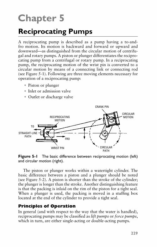
P1: FCH
GB098-05 GB098-Miller September 13, 2004 17:54 Char Count= 0
Chapter 5Reciprocating PumpsA reciprocating pump is described as a pump having a to-and-fro motion. Its motion is backward and forward or upward anddownward—as distinguished from the circular motion of centrifu-gal and rotary pumps. A piston or plunger differentiates the recipro-cating pump from a centrifugal or rotary pump. In a reciprocatingpump, the reciprocating motion of the wrist pin is converted to acircular motion by means of a connecting link or connecting rod(see Figure 5-1). Following are three moving elements necessary foroperation of a reciprocating pump:
� Piston or plunger� Inlet or admission valve� Outlet or discharge valve
CRANK PIN
CIRCULARMOTIONRECIPROCATING
MOTION
FRO
TO
STRAIGHT-LINEPATH
WRIST PIN CIRCULARPATH
Figure 5-1 The basic difference between reciprocating motion (left)and circular motion (right).
The piston or plunger works within a watertight cylinder. Thebasic difference between a piston and a plunger should be noted(see Figure 5-2). A piston is shorter than the stroke of the cylinder;the plunger is longer than the stroke. Another distinguishing featureis that the packing is inlaid on the rim of the piston for a tight seal.When a plunger is used, the packing is moved in a stuffing boxlocated at the end of the cylinder to provide a tight seal.
Principles of OperationIn general (and with respect to the way that the water is handled),reciprocating pumps may be classified as lift pumps or force pumps,which in turn, are either single-acting or double-acting pumps.
229
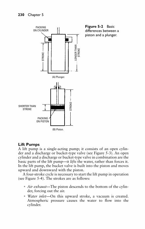
P1: FCH
GB098-05 GB098-Miller September 13, 2004 17:54 Char Count= 0
230 Chapter 5
PACKINGON CYLINDER
STRO
KE
STRO
KE
LON
GER
THAN
STRO
KE
SHORTER THANSTROKE
PACKINGON PISTON
(A) Plunger.
(B) Piston.
Figure 5-2 Basicdifferences between apiston and a plunger.
Lift PumpsA lift pump is a single-acting pump; it consists of an open cylin-der and a discharge or bucket-type valve (see Figure 5-3). An opencylinder and a discharge or bucket-type valve in combination are thebasic parts of the lift pump—it lifts the water, rather than forces it.In the lift pump, the bucket valve is built into the piston and movesupward and downward with the piston.
A four-stroke cycle is necessary to start the lift pump in operation(see Figure 5-4). The strokes are as follows:
� Air exhaust—The piston descends to the bottom of the cylin-der, forcing out the air.
� Water inlet—On this upward stroke, a vacuum is created.Atmospheric pressure causes the water to flow into thecylinder.
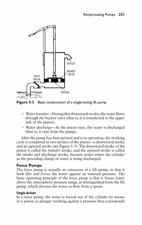
P1: FCH
GB098-05 GB098-Miller September 13, 2004 17:54 Char Count= 0
Reciprocating Pumps 231
OUTLET
INLETVALVE
BUCKETVALVE
PISTON
Figure 5-3 Basic construction of a single-acting lift pump.
� Water transfer—During this downward stroke, the water flowsthrough the bucket valve (that is, it is transferred to the upperside of the piston).
� Water discharge—As the piston rises, the water is discharged(that is, it runs from the pump).
After the pump has been primed and is in operation, the workingcycle is completed in two strokes of the piston—a downward strokeand an upward stroke (see Figure 5-5). The downward stroke of thepiston is called the transfer stroke, and the upward stroke is calledthe intake and discharge stroke, because water enters the cylinderas the preceding charge of water is being discharged.
Force PumpsThe force pump is actually an extension of a lift pump, in that itboth lifts and forces the water against an external pressure. Thebasic operating principle of the force pump is that it forces waterabove the atmospheric pressure range, as distinguished from the liftpump, which elevates the water to flow from a spout.
Single-ActionIn a force pump, the water is forced out of the cylinder by meansof a piston or plunger working against a pressure that corresponds
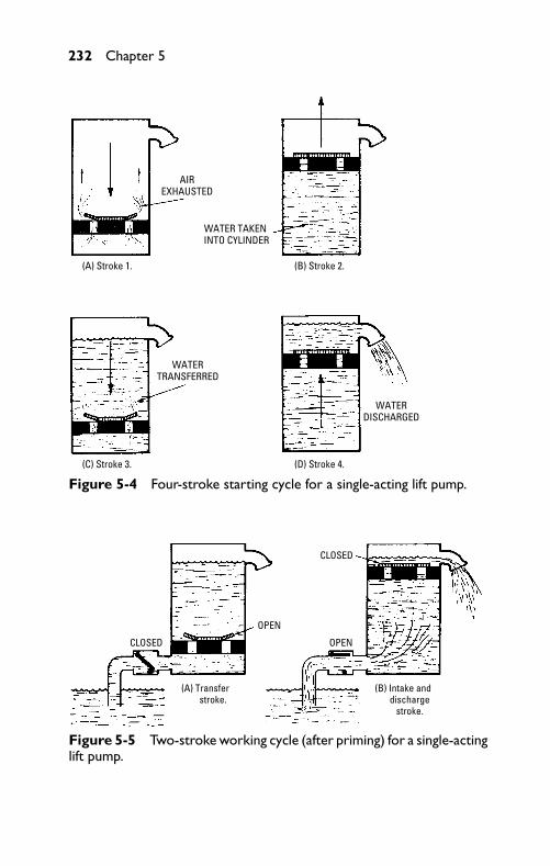
P1: FCH
GB098-05 GB098-Miller September 13, 2004 17:54 Char Count= 0
232 Chapter 5
(A) Stroke 1.
(C) Stroke 3. (D) Stroke 4.
(B) Stroke 2.
AIREXHAUSTED
WATER TAKEN INTO CYLINDER
WATERTRANSFERRED
WATERDISCHARGED
Figure 5-4 Four-stroke starting cycle for a single-acting lift pump.
CLOSED
CLOSED
OPEN
OPEN
(A) Transfer stroke.
(B) Intake and discharge
stroke.
Figure 5-5 Two-stroke working cycle (after priming) for a single-actinglift pump.
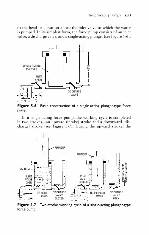
P1: FCH
GB098-05 GB098-Miller September 13, 2004 17:54 Char Count= 0
Reciprocating Pumps 233
to the head or elevation above the inlet valve to which the wateris pumped. In its simplest form, the force pump consists of an inletvalve, a discharge valve, and a single-acting plunger (see Figure 5-6).
INLETVALVE
SINGLE-ACTINGPLUNGER
LIFTDISCHARGE
VALVE
HEAD
Figure 5-6 Basic construction of a single-acting plunger-type forcepump.
In a single-acting force pump, the working cycle is completedin two strokes—an upward (intake) stroke and a downward (dis-charge) stroke (see Figure 5-7). During the upward stroke, the
PLUNGER
PLUNGER
VACUUM
INLETVALVEOPEN
INLETVALVE
CLOSED
DISCHARGEVALVE
CLOSED
DISCHARGEVALVEOPEN
DYN
AMIC
HEA
DPU
MPE
D AG
AIN
ST
(A) Intake stroke.
(B) Discharge stroke.
Figure 5-7 Two-stroke working cycle of a single-acting plunger-typeforce pump.
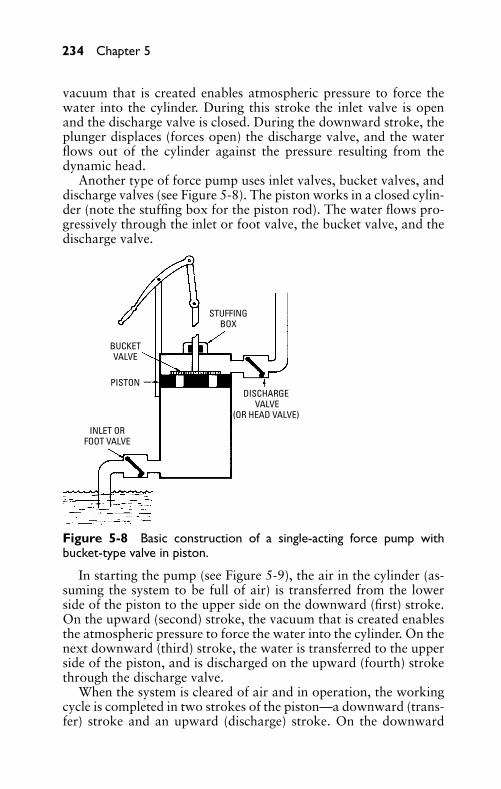
P1: FCH
GB098-05 GB098-Miller September 13, 2004 17:54 Char Count= 0
234 Chapter 5
vacuum that is created enables atmospheric pressure to force thewater into the cylinder. During this stroke the inlet valve is openand the discharge valve is closed. During the downward stroke, theplunger displaces (forces open) the discharge valve, and the waterflows out of the cylinder against the pressure resulting from thedynamic head.
Another type of force pump uses inlet valves, bucket valves, anddischarge valves (see Figure 5-8). The piston works in a closed cylin-der (note the stuffing box for the piston rod). The water flows pro-gressively through the inlet or foot valve, the bucket valve, and thedischarge valve.
PISTON
BUCKETVALVE
STUFFINGBOX
INLET ORFOOT VALVE
DISCHARGE VALVE
(OR HEAD VALVE)
Figure 5-8 Basic construction of a single-acting force pump withbucket-type valve in piston.
In starting the pump (see Figure 5-9), the air in the cylinder (as-suming the system to be full of air) is transferred from the lowerside of the piston to the upper side on the downward (first) stroke.On the upward (second) stroke, the vacuum that is created enablesthe atmospheric pressure to force the water into the cylinder. On thenext downward (third) stroke, the water is transferred to the upperside of the piston, and is discharged on the upward (fourth) strokethrough the discharge valve.
When the system is cleared of air and in operation, the workingcycle is completed in two strokes of the piston—a downward (trans-fer) stroke and an upward (discharge) stroke. On the downward
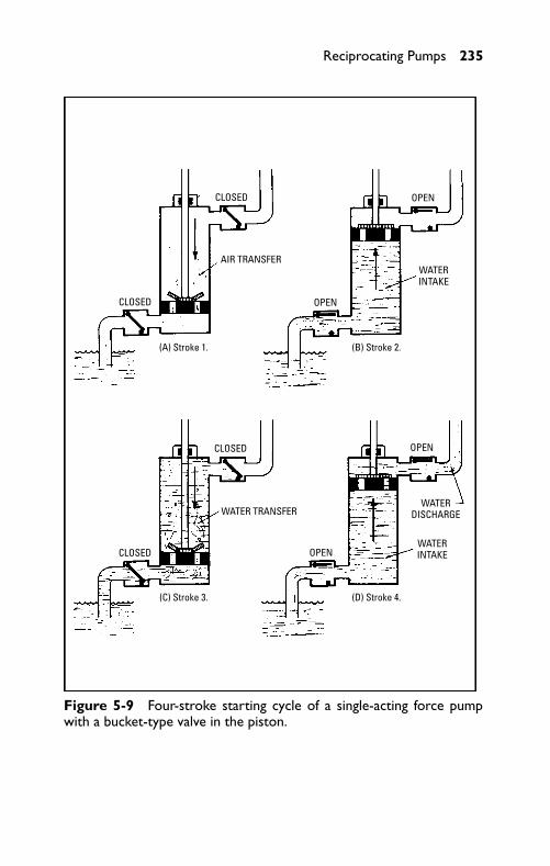
P1: FCH
GB098-05 GB098-Miller September 13, 2004 17:54 Char Count= 0
Reciprocating Pumps 235
CLOSED
CLOSED
CLOSED
CLOSED
AIR TRANSFER
WATER TRANSFER
OPEN
OPEN
OPEN
OPEN
WATERINTAKE
WATERINTAKE
WATERDISCHARGE
(A) Stroke 1.
(C) Stroke 3. (D) Stroke 4.
(B) Stroke 2.
Figure 5-9 Four-stroke starting cycle of a single-acting force pumpwith a bucket-type valve in the piston.
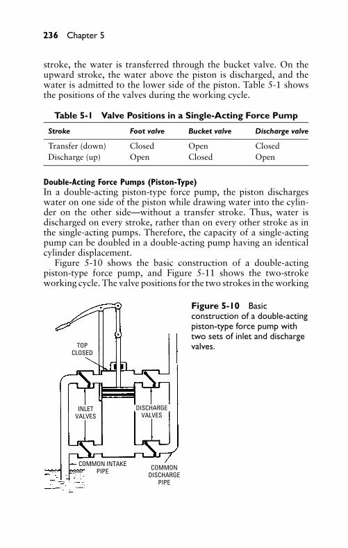
P1: FCH
GB098-05 GB098-Miller September 13, 2004 17:54 Char Count= 0
236 Chapter 5
stroke, the water is transferred through the bucket valve. On theupward stroke, the water above the piston is discharged, and thewater is admitted to the lower side of the piston. Table 5-1 showsthe positions of the valves during the working cycle.
Table 5-1 Valve Positions in a Single-Acting Force Pump
Stroke Foot valve Bucket valve Discharge valve
Transfer (down) Closed Open ClosedDischarge (up) Open Closed Open
Double-Acting Force Pumps (Piston-Type)In a double-acting piston-type force pump, the piston dischargeswater on one side of the piston while drawing water into the cylin-der on the other side—without a transfer stroke. Thus, water isdischarged on every stroke, rather than on every other stroke as inthe single-acting pumps. Therefore, the capacity of a single-actingpump can be doubled in a double-acting pump having an identicalcylinder displacement.
Figure 5-10 shows the basic construction of a double-actingpiston-type force pump, and Figure 5-11 shows the two-strokeworking cycle. The valve positions for the two strokes in the working
TOPCLOSED
INLETVALVES
DISCHARGEVALVES
COMMON INTAKEPIPE COMMON
DISCHARGEPIPE
Figure 5-10 Basicconstruction of a double-actingpiston-type force pump withtwo sets of inlet and dischargevalves.
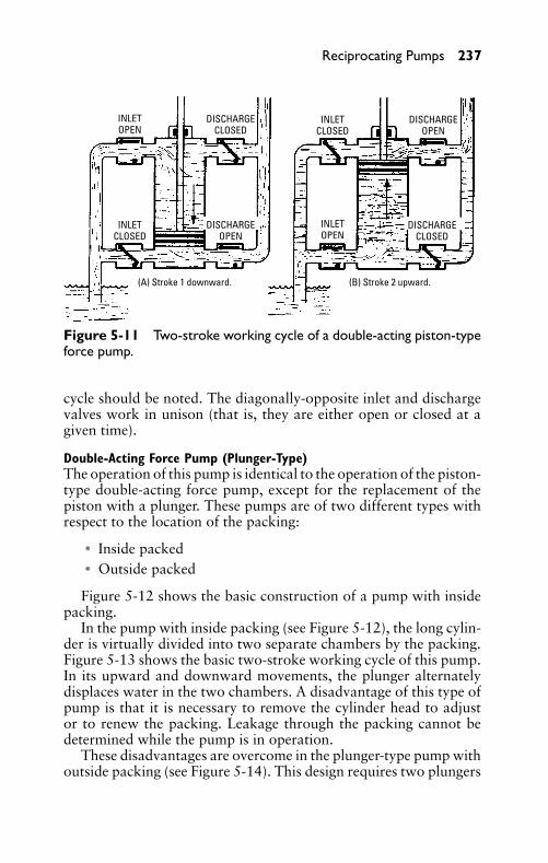
P1: FCH
GB098-05 GB098-Miller September 13, 2004 17:54 Char Count= 0
Reciprocating Pumps 237
INLETOPEN
INLETOPEN
INLETCLOSED
INLETCLOSED
DISCHARGECLOSED
DISCHARGECLOSED
DISCHARGEOPEN
DISCHARGEOPEN
(A) Stroke 1 downward. (B) Stroke 2 upward.
Figure 5-11 Two-stroke working cycle of a double-acting piston-typeforce pump.
cycle should be noted. The diagonally-opposite inlet and dischargevalves work in unison (that is, they are either open or closed at agiven time).
Double-Acting Force Pump (Plunger-Type)The operation of this pump is identical to the operation of the piston-type double-acting force pump, except for the replacement of thepiston with a plunger. These pumps are of two different types withrespect to the location of the packing:
� Inside packed� Outside packed
Figure 5-12 shows the basic construction of a pump with insidepacking.
In the pump with inside packing (see Figure 5-12), the long cylin-der is virtually divided into two separate chambers by the packing.Figure 5-13 shows the basic two-stroke working cycle of this pump.In its upward and downward movements, the plunger alternatelydisplaces water in the two chambers. A disadvantage of this type ofpump is that it is necessary to remove the cylinder head to adjustor to renew the packing. Leakage through the packing cannot bedetermined while the pump is in operation.
These disadvantages are overcome in the plunger-type pump withoutside packing (see Figure 5-14). This design requires two plungers
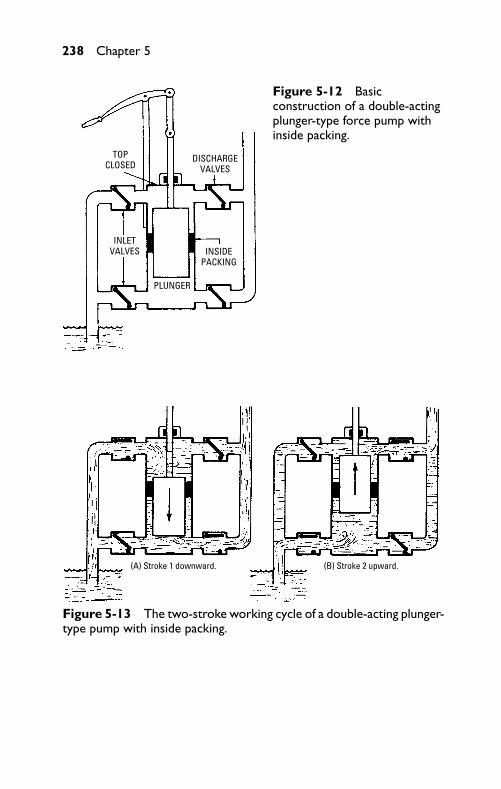
P1: FCH
GB098-05 GB098-Miller September 13, 2004 17:54 Char Count= 0
238 Chapter 5
TOPCLOSED
DISCHARGEVALVES
INLETVALVES INSIDE
PACKING
PLUNGER
Figure 5-12 Basicconstruction of a double-actingplunger-type force pump withinside packing.
(A) Stroke 1 downward. (B) Stroke 2 upward.
Figure 5-13 The two-stroke working cycle of a double-acting plunger-type pump with inside packing.
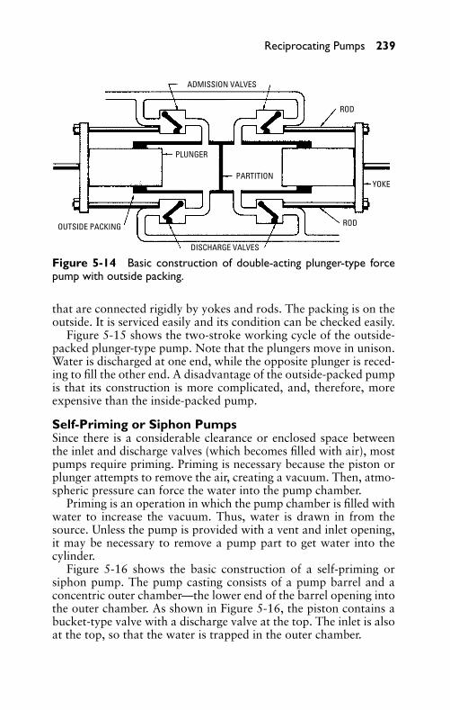
P1: FCH
GB098-05 GB098-Miller September 13, 2004 17:54 Char Count= 0
Reciprocating Pumps 239
ADMISSION VALVES
PLUNGER
PARTITION
ROD
ROD
YOKE
OUTSIDE PACKING
DISCHARGE VALVES
Figure 5-14 Basic construction of double-acting plunger-type forcepump with outside packing.
that are connected rigidly by yokes and rods. The packing is on theoutside. It is serviced easily and its condition can be checked easily.
Figure 5-15 shows the two-stroke working cycle of the outside-packed plunger-type pump. Note that the plungers move in unison.Water is discharged at one end, while the opposite plunger is reced-ing to fill the other end. A disadvantage of the outside-packed pumpis that its construction is more complicated, and, therefore, moreexpensive than the inside-packed pump.
Self-Priming or Siphon PumpsSince there is a considerable clearance or enclosed space betweenthe inlet and discharge valves (which becomes filled with air), mostpumps require priming. Priming is necessary because the piston orplunger attempts to remove the air, creating a vacuum. Then, atmo-spheric pressure can force the water into the pump chamber.
Priming is an operation in which the pump chamber is filled withwater to increase the vacuum. Thus, water is drawn in from thesource. Unless the pump is provided with a vent and inlet opening,it may be necessary to remove a pump part to get water into thecylinder.
Figure 5-16 shows the basic construction of a self-priming orsiphon pump. The pump casting consists of a pump barrel and aconcentric outer chamber—the lower end of the barrel opening intothe outer chamber. As shown in Figure 5-16, the piston contains abucket-type valve with a discharge valve at the top. The inlet is alsoat the top, so that the water is trapped in the outer chamber.
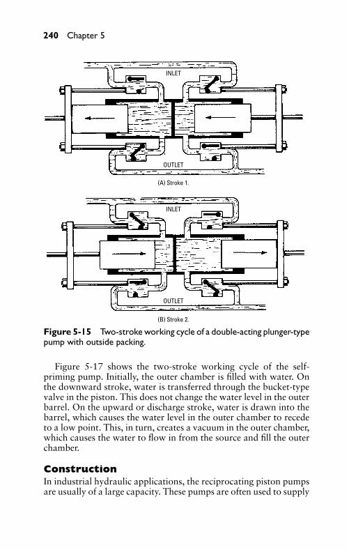
P1: FCH
GB098-05 GB098-Miller September 13, 2004 17:54 Char Count= 0
240 Chapter 5
INLET
OUTLET
INLET
OUTLET
(A) Stroke 1.
(B) Stroke 2.
Figure 5-15 Two-stroke working cycle of a double-acting plunger-typepump with outside packing.
Figure 5-17 shows the two-stroke working cycle of the self-priming pump. Initially, the outer chamber is filled with water. Onthe downward stroke, water is transferred through the bucket-typevalve in the piston. This does not change the water level in the outerbarrel. On the upward or discharge stroke, water is drawn into thebarrel, which causes the water level in the outer chamber to recedeto a low point. This, in turn, creates a vacuum in the outer chamber,which causes the water to flow in from the source and fill the outerchamber.
ConstructionIn industrial hydraulic applications, the reciprocating piston pumpsare usually of a large capacity. These pumps are often used to supply
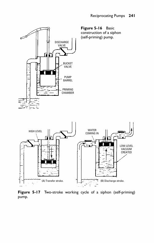
P1: FCH
GB098-05 GB098-Miller September 13, 2004 17:54 Char Count= 0
Reciprocating Pumps 241
DISCHARGEVALVE
BUCKETVALVE
PUMPBARREL
PRIMINGCHAMBER
Figure 5-16 Basicconstruction of a siphon(self-priming) pump.
HIGH LEVEL WATERCOMING IN
LOW-LEVELVACUUMCREATED
(A) Transfer stroke. (B) Discharge stroke.
Figure 5-17 Two-stroke working cycle of a siphon (self-priming)pump.
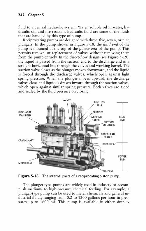
P1: FCH
GB098-05 GB098-Miller September 13, 2004 17:54 Char Count= 0
242 Chapter 5
fluid to a central hydraulic system. Water, soluble oil in water, hy-draulic oil, and fire-resistant hydraulic fluid are some of the fluidsthat are handled by this type of pump.
Reciprocating pumps are designed with three, five, seven, or nineplungers. In the pump shown in Figure 5-18, the fluid end of thepump is mounted at the top of the power end of the pump. Thispermits removal or replacement of valves without removing themfrom the pump entirely. In the direct-flow design (see Figure 5-19),the liquid is passed from the suction end to the discharge end in astraight horizontal line through the valves and working barrel. Thesuction valve closes as the plunger moves downward, and the liquidis forced through the discharge valves, which open against lightspring pressure. When the plunger moves upward, the dischargevalves close and liquid is drawn inward through the suction valves,which open against similar spring pressure. Both valves are aidedand sealed by the fluid pressure on closing.
VALVES
DISCHARGEMANIFOLD
STUFFINGBOX
CRANKSHAFT
MAIN FRAME
PLUNGER
WORKINGBARREL
SUCTIONMANIFOLD
CROSSHEADCRADLE
CROSSHEAD
OIL PUMP
FLUIDEND
POWEREND
Figure 5-18 The internal parts of a reciprocating piston pump.
The plunger-type pumps are widely used in industry to accom-plish medium- to high-pressure chemical feeding. For example, aplunger-type pump can be used to meter chemicals and general in-dustrial fluids, ranging from 0.2 to 1200 gallons per hour in pres-sures up to 1600 psi. This pump is available in either simplex
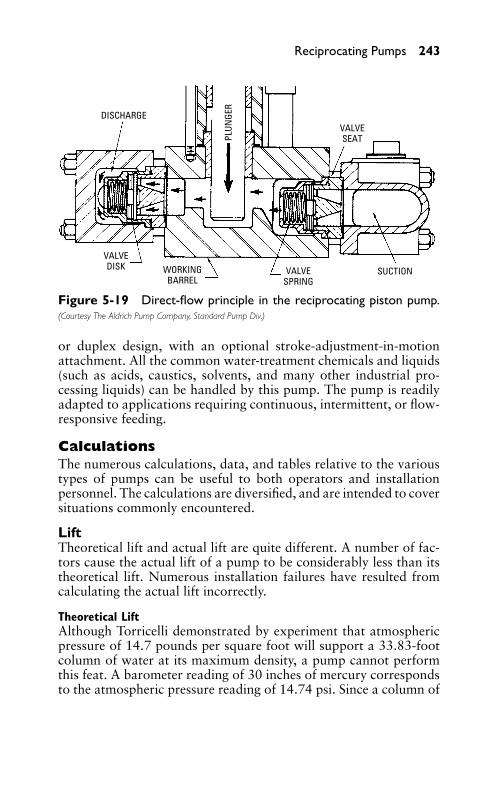
P1: FCH
GB098-05 GB098-Miller September 13, 2004 17:54 Char Count= 0
Reciprocating Pumps 243
DISCHARGEVALVESEAT
VALVEDISK WORKING
BARRELVALVE
SPRINGSUCTION
PLUN
GER
Figure 5-19 Direct-flow principle in the reciprocating piston pump.(Courtesy The Aldrich Pump Company, Standard Pump Div.)
or duplex design, with an optional stroke-adjustment-in-motionattachment. All the common water-treatment chemicals and liquids(such as acids, caustics, solvents, and many other industrial pro-cessing liquids) can be handled by this pump. The pump is readilyadapted to applications requiring continuous, intermittent, or flow-responsive feeding.
CalculationsThe numerous calculations, data, and tables relative to the varioustypes of pumps can be useful to both operators and installationpersonnel. The calculations are diversified, and are intended to coversituations commonly encountered.
LiftTheoretical lift and actual lift are quite different. A number of fac-tors cause the actual lift of a pump to be considerably less than itstheoretical lift. Numerous installation failures have resulted fromcalculating the actual lift incorrectly.
Theoretical LiftAlthough Torricelli demonstrated by experiment that atmosphericpressure of 14.7 pounds per square foot will support a 33.83-footcolumn of water at its maximum density, a pump cannot performthis feat. A barometer reading of 30 inches of mercury correspondsto the atmospheric pressure reading of 14.74 psi. Since a column of
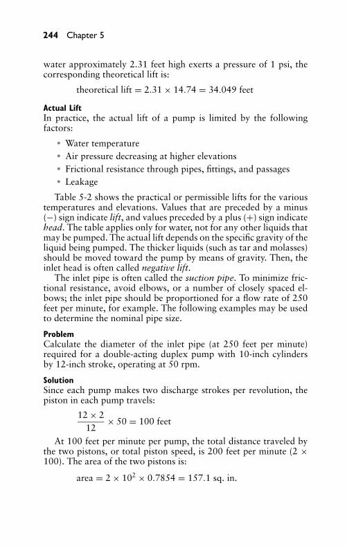
P1: FCH
GB098-05 GB098-Miller September 13, 2004 17:54 Char Count= 0
244 Chapter 5
water approximately 2.31 feet high exerts a pressure of 1 psi, thecorresponding theoretical lift is:
theoretical lift = 2.31 × 14.74 = 34.049 feet
Actual LiftIn practice, the actual lift of a pump is limited by the followingfactors:
� Water temperature� Air pressure decreasing at higher elevations� Frictional resistance through pipes, fittings, and passages� Leakage
Table 5-2 shows the practical or permissible lifts for the varioustemperatures and elevations. Values that are preceded by a minus(−) sign indicate lift, and values preceded by a plus (+) sign indicatehead. The table applies only for water, not for any other liquids thatmay be pumped. The actual lift depends on the specific gravity of theliquid being pumped. The thicker liquids (such as tar and molasses)should be moved toward the pump by means of gravity. Then, theinlet head is often called negative lift.
The inlet pipe is often called the suction pipe. To minimize fric-tional resistance, avoid elbows, or a number of closely spaced el-bows; the inlet pipe should be proportioned for a flow rate of 250feet per minute, for example. The following examples may be usedto determine the nominal pipe size.
ProblemCalculate the diameter of the inlet pipe (at 250 feet per minute)required for a double-acting duplex pump with 10-inch cylindersby 12-inch stroke, operating at 50 rpm.
SolutionSince each pump makes two discharge strokes per revolution, thepiston in each pump travels:
12 × 212
× 50 = 100 feet
At 100 feet per minute per pump, the total distance traveled bythe two pistons, or total piston speed, is 200 feet per minute (2 ×100). The area of the two pistons is:
area = 2 × 102 × 0.7854 = 157.1 sq. in.
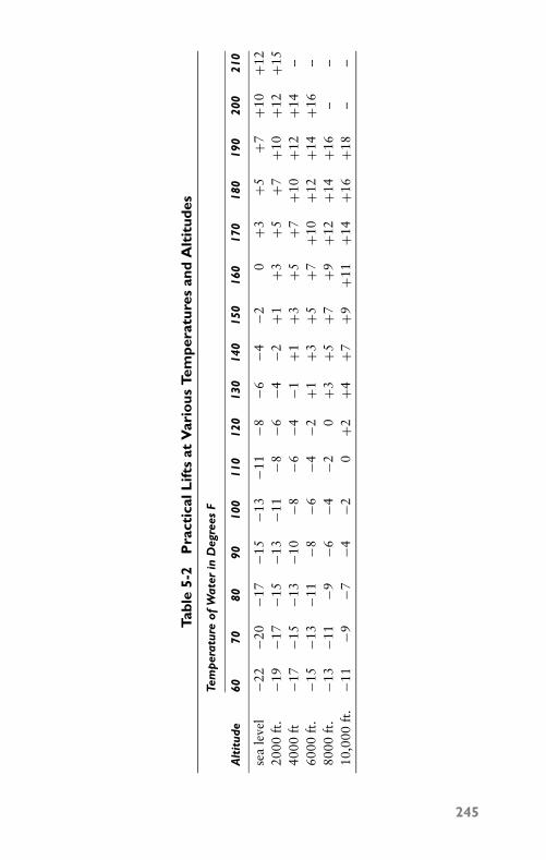
P1: FCH
GB098-05 GB098-Miller September 13, 2004 17:54 Char Count= 0
Tabl
e5-
2P
ract
ical
Lift
sat
Var
ious
Tem
pera
ture
san
dA
ltit
udes
Tem
per
atur
eof
Wat
erin
Deg
rees
F
Alt
itud
e60
7080
9010
011
012
013
014
015
016
017
018
019
020
021
0
sea
leve
l−2
2−2
0−1
7−1
5−1
3−1
1−8
−6−4
−20
+3+5
+7+1
0+1
220
00ft
.−1
9−1
7−1
5−1
3−1
1−8
−6−4
−2+1
+3+5
+7+1
0+1
2+1
540
00ft
−17
−15
−13
−10
−8−6
−4−1
+1+3
+5+7
+10
+12
+14
–60
00ft
.−1
5−1
3−1
1−8
−6−4
−2+1
+3+5
+7+1
0+1
2+1
4+1
6–
8000
ft.
−13
−11
−9−6
−4−2
0+3
+5+7
+9+1
2+1
4+1
6–
–10
,000
ft.
−11
−9−7
−4−2
0+2
+4+7
+9+1
1+1
4+1
6+1
8–
–
245
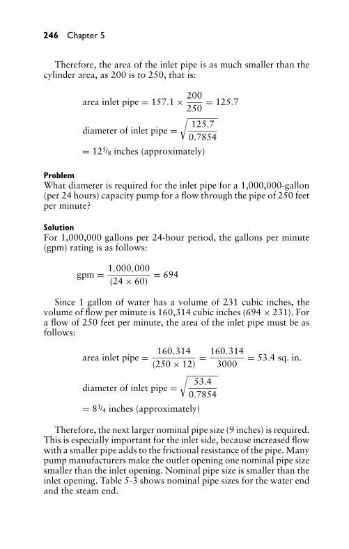
P1: FCH
GB098-05 GB098-Miller September 13, 2004 17:54 Char Count= 0
246 Chapter 5
Therefore, the area of the inlet pipe is as much smaller than thecylinder area, as 200 is to 250, that is:
area inlet pipe = 157.1 × 200250
= 125.7
diameter of inlet pipe =√
125.70.7854
= 125/8 inches (approximately)
ProblemWhat diameter is required for the inlet pipe for a 1,000,000-gallon(per 24 hours) capacity pump for a flow through the pipe of 250 feetper minute?
SolutionFor 1,000,000 gallons per 24-hour period, the gallons per minute(gpm) rating is as follows:
gpm = 1,000,000(24 × 60)
= 694
Since 1 gallon of water has a volume of 231 cubic inches, thevolume of flow per minute is 160,314 cubic inches (694 × 231). Fora flow of 250 feet per minute, the area of the inlet pipe must be asfollows:
area inlet pipe = 160,314(250 × 12)
= 160,3143000
= 53.4 sq. in.
diameter of inlet pipe =√
53.40.7854
= 81/4 inches (approximately)
Therefore, the next larger nominal pipe size (9 inches) is required.This is especially important for the inlet side, because increased flowwith a smaller pipe adds to the frictional resistance of the pipe. Manypump manufacturers make the outlet opening one nominal pipe sizesmaller than the inlet opening. Nominal pipe size is smaller than theinlet opening. Table 5-3 shows nominal pipe sizes for the water endand the steam end.
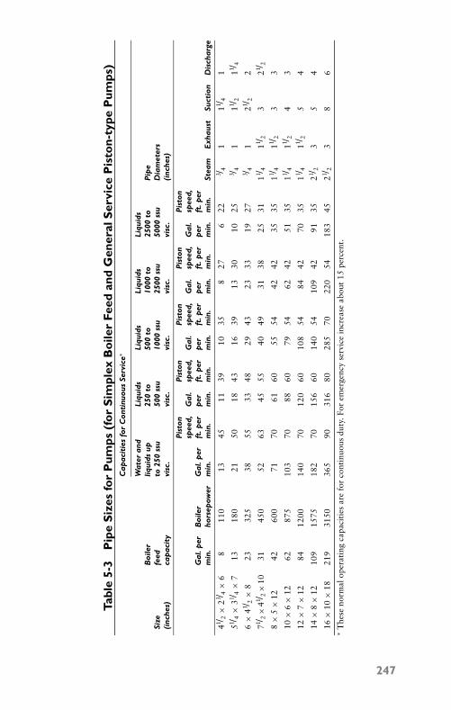
P1: FCH
GB098-05 GB098-Miller September 13, 2004 17:54 Char Count= 0
Tabl
e5-
3P
ipe
Siz
esfo
rP
umps
(fo
rS
impl
exB
oile
rFe
edan
dG
ener
alS
ervi
ceP
isto
n-ty
peP
umps
)C
apac
itie
sfo
rC
onti
nuou
sSe
rvic
e∗
Wat
eran
dLi
quid
sLi
quid
sLi
quid
sLi
quid
sB
oile
rliq
uids
up25
0to
500
to10
00to
2500
toP
ipe
Size
feed
to25
0ss
u50
0ss
u10
00ss
u25
00ss
u50
00ss
uD
iam
eter
s(i
nche
s)ca
pac
ity
visc
.vi
sc.
visc
.vi
sc.
visc
.(i
nche
s)
Pis
ton
Pis
ton
Pis
ton
Pis
ton
Pis
ton
spee
d,G
al.
spee
d,G
al.
spee
d,G
al.
spee
d,G
al.
spee
d,G
al.p
erB
oile
rG
al.p
erft
.per
per
ft.p
erp
erft
.per
per
ft.p
erp
erft
.per
min
.ho
rsep
ower
min
.m
in.
min
.m
in.
min
.m
in.
min
.m
in.
min
.m
in.
Stea
mE
xhau
stSu
ctio
nD
isch
arge
41 / 2×
23 / 4×
68
110
1345
1139
1035
827
622
3 / 41
11 / 41
51 / 4×
31 / 4×
71 3
180
2150
1843
1639
1330
1025
3 / 41
11 / 211 / 4
6×
41 / 2×
823
325
3855
3348
2943
2333
1927
3 / 41
21 / 22
71 / 2×
41 / 2×
1031
450
5263
4555
4049
3138
2531
11 / 411 / 2
321 / 2
8×
5×
1242
600
7170
6160
5554
4242
3535
11 / 411 / 2
33
10×
6×
1262
875
103
7088
6079
5462
4251
3511 / 4
11 / 24
3
12×
7×
1284
1200
140
7012
060
108
5484
4270
3511 / 4
11 / 25
4
14×
8×
1210
915
7518
270
156
6014
054
109
4291
3521 / 2
35
4
16×
10×
1821
931
5036
590
316
8028
570
220
5418
345
21 / 23
86
∗T
hese
norm
alop
erat
ing
capa
citi
esar
efo
rco
ntin
uous
duty
.For
emer
genc
yse
rvic
ein
crea
seab
out
15pe
rcen
t.
247
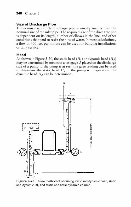
P1: FCH
GB098-05 GB098-Miller September 13, 2004 17:54 Char Count= 0
248 Chapter 5
Size of Discharge PipeThe nominal size of the discharge pipe is usually smaller than thenominal size of the inlet pipe. The required size of the discharge lineis dependent on its length, number of elbows in the line, and otherconditions that tend to resist the flow of water. In most calculations,a flow of 400 feet per minute can be used for building installationsor tank service.
HeadAs shown in Figure 5-20, the static head (Hs ) or dynamic head (Hd)may be determined by means of a test gage A placed on the dischargeside of a pump. If the pump is at rest, the gage reading can be usedto determine the static head Hs . If the pump is in operation, thedynamic head Hd can be determined.
TOTA
L ST
ATIC
COL
UMN
M
T
B
W
N
A
HSHD
LD LS
Figure 5-20 Gage method of obtaining static and dynamic head, staticand dynamic lift, and static and total dynamic column.
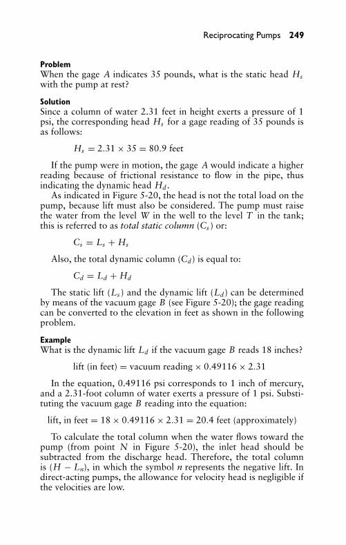
P1: FCH
GB098-05 GB098-Miller September 13, 2004 17:54 Char Count= 0
Reciprocating Pumps 249
ProblemWhen the gage A indicates 35 pounds, what is the static head Hswith the pump at rest?
SolutionSince a column of water 2.31 feet in height exerts a pressure of 1psi, the corresponding head Hs for a gage reading of 35 pounds isas follows:
Hs = 2.31 × 35 = 80.9 feet
If the pump were in motion, the gage A would indicate a higherreading because of frictional resistance to flow in the pipe, thusindicating the dynamic head Hd .
As indicated in Figure 5-20, the head is not the total load on thepump, because lift must also be considered. The pump must raisethe water from the level W in the well to the level T in the tank;this is referred to as total static column (Cs ) or:
Cs = Ls + Hs
Also, the total dynamic column (Cd) is equal to:
Cd = Ld + Hd
The static lift (Ls ) and the dynamic lift (Ld) can be determinedby means of the vacuum gage B (see Figure 5-20); the gage readingcan be converted to the elevation in feet as shown in the followingproblem.
ExampleWhat is the dynamic lift Ld if the vacuum gage B reads 18 inches?
lift (in feet) = vacuum reading × 0.49116 × 2.31
In the equation, 0.49116 psi corresponds to 1 inch of mercury,and a 2.31-foot column of water exerts a pressure of 1 psi. Substi-tuting the vacuum gage B reading into the equation:
lift, in feet = 18 × 0.49116 × 2.31 = 20.4 feet (approximately)
To calculate the total column when the water flows toward thepump (from point N in Figure 5-20), the inlet head should besubtracted from the discharge head. Therefore, the total columnis (H − Ln), in which the symbol n represents the negative lift. Indirect-acting pumps, the allowance for velocity head is negligible ifthe velocities are low.
P1: FCH
GB098-05 GB098-Miller September 13, 2004 17:54 Char Count= 0
250 Chapter 5
DisplacementThe volume of fluid that is displaced by the piston or plunger in asingle stroke is called displacement in a reciprocating pump. Dis-placement is expressed as cubic inches per stroke, cubic inches perminute, and gallons per minute. Displacement is more commonlystated in terms of cubic inches per stroke. To determine piston dis-placement, in cubic inches per stroke, multiply the effective area ofthe piston or plunger by the length of the stroke.
ProblemCalculate the displacement, in cubic inches per stroke, in a double-acting simplex reciprocating pump with a water cylinder that is 5inches by 12 inches, with a 1-inch piston rod.
SolutionThe effective piston area is:
piston area = (5)2 × 0.7854 = 19.635 sq. in.
1/2 area piston rod = (1)2 × 0.78542
= 0.393
total effective area of piston = 19.242 sq. in.
(the rod reduces displacement on only one side of piston;therefore, one-half the rod area is an average)
displacement = effective piston area × stroke
= 19.242 × 12
= 230.9 cu in./stroke
To determine the displacement, in cubic inches per minute, multi-ply the cylinder displacement per stroke by the number of discharg-ing strokes per minute. Thus, in the preceding problem, each strokeis a discharging stroke, because the pump is a double-acting pump.Therefore, if the pump is operating at 92 strokes per minute:
displacement = 230.9 × 92
= 21,242.8 cubic inches per minute
To determine the displacement, in gallons per minute, divide thedisplacement per minute by 231 (volume of 1 gallon of water).Therefore, displacement is:
displacement = 21,242.8231
= 91.96 gal/min
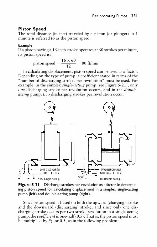
P1: FCH
GB098-05 GB098-Miller September 13, 2004 17:54 Char Count= 0
Reciprocating Pumps 251
Piston SpeedThe total distance (in feet) traveled by a piston (or plunger) in 1minute is referred to as the piston speed.
ExampleIf a piston having a 16-inch stroke operates at 60 strokes per minute,its piston speed is:
piston speed = 16 × 6012
= 80 ft/min
In calculating displacement, piston speed can be used as a factor.Depending on the type of pump, a coefficient stated in terms of the“number of discharging strokes per revolution” must be used. Forexample, in the simplex single-acting pump (see Figure 5-21), onlyone discharging stroke per revolution occurs, and in the double-acting pump, two discharging strokes per revolution occur.
ONE DISCHARGESTROKE PER REV.
TWO DISCHARGESTROKES PER REV.
(A) Single acting. (B) Double acting.
Figure 5-21 Discharge strokes per revolution as a factor in determin-ing piston speed for calculating displacement in a simplex single-actingpump (left) and double-acting pump (right).
Since piston speed is based on both the upward (charging) strokeand the downward (discharging) stroke, and since only one dis-charging stroke occurs per two-stroke revolution in a single-actingpump, the coefficient is one-half (0.5). That is, the piston speed mustbe multiplied by 1/2, or 0.5, as in the following problem.
P1: FCH
GB098-05 GB098-Miller September 13, 2004 17:54 Char Count= 0
252 Chapter 5
ProblemWhat is the displacement per revolution in a single-acting pumpwith a 300-cubic inch displacement, operating at 100 rpm?
SolutionSince, in a single-acting pump, only one discharging stroke per rev-olution occurs, the displacement per revolution is:
displacement per revolution = 300 × 0.5
= 150 cubic inchesSince two discharging strokes per revolution occur in a double-
acting pump, the coefficient is one-half (0.5)—that is, if the piston inthe preceding problem were a double-acting pump, the displacementper revolution would be:
displacement per revolution = 300 × 1
= 300 cubic inchesSince the displacement per revolution is equal to the displacement
times coefficient (displacement × coefficient), the various combina-tions can be tabulated as follows:
Single-Acting Double-ActingSimplex 0.5 1.0Duplex 1.0 2.0Triplex 1.5 3.0
Therefore, a triplex single-acting pump with a displacement of300 cubic inches per cylinder has a displacement per revolution of450 cubic inches (300 × 1.5), and a duplex double-acting pump withthe displacement per cylinder has a displacement per revolution of600 cubic inches (300 × 2.0).
SlipIn the foregoing problems, the displacements mentioned were theo-retical displacements. In actual operating conditions, a pump cannotdischarge a volume of water that is equal to its theoretical displace-ment because of slip through the valves and leakage. The slip isgenerally expressed as a percentage of the displacement. It is thatamount by which the volume of water delivered per stroke falls shortof the pump’s displacement.
ProblemWhat is the slip (in percentage of the displacement) in a pump witha displacement of 300 cubic inches per stroke, but which dischargesonly 285 cubic inches of water per stroke?
P1: FCH
GB098-05 GB098-Miller September 13, 2004 17:54 Char Count= 0
Reciprocating Pumps 253
SolutionThe slip is 15 cubic inches (300 − 285); Therefore:
slip = 15300
× 100 = 5%
That means the percentage is determined by:� The percentage of slip. It varies from 2 to 10 percent.� The type of pump. It is piston or plunger.� The condition of the pump.� The pressure that the pump is working against.
In actual practice, a slip of 2 percent is a common value for aplunger-type pump. For light-service piston pumps, the slip is ap-proximately 5 percent. A slip of 10 percent is common for pressure-type piston pumps. Another factor that may reduce the output of ahigh-speed reciprocating pump occurs when the speed is too high forthe water to flow through the inlet valves fast enough to completelyfill the cylinder.
In pumps with bucket valves, operating on low lift where thecolumn of water has sufficient dynamic inertia to continue in motionduring a portion (or all) of the return stroke, the discharge volumemay be greater than the displacement. This condition is referred toas negative slip.
CapacityThe capacity of a pump is the actual volume of water or fluid de-livered. It is usually stated in terms of gallons per stroke or gallonsper minute when discharging at a given speed.
ProblemA single-acting pump with a displacement of 300 cubic inches isoperating at 100 strokes per minute. What is its capacity in gallonsper minute with a 5 percent slip?
SolutionFor a single-acting pump, there are 50 discharging strokes perminute (100 ÷ 2). Hence:
displacement/min = 300 × 50 = 15,000 cu in.
5% slip = 15,000 × 0.05 = 750 cu in.
capacity/min = 15,000 − 750 = 14,250 cu in.
capacity/min = 14,250231
= 61.69 gal
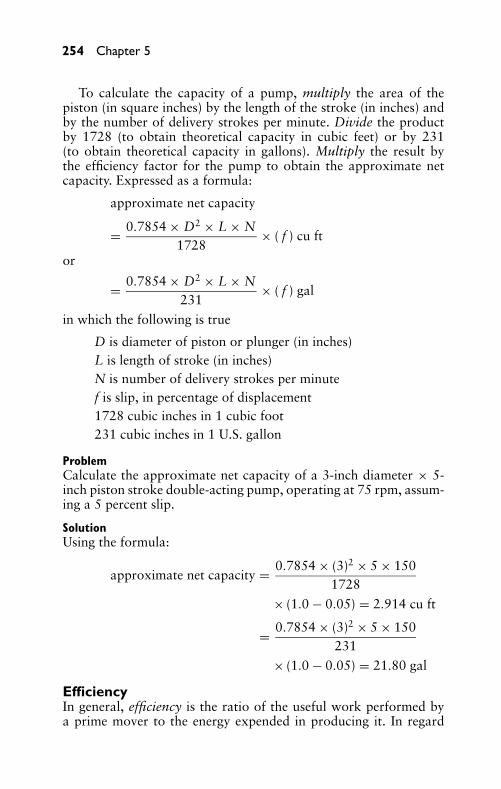
P1: FCH
GB098-05 GB098-Miller September 13, 2004 17:54 Char Count= 0
254 Chapter 5
To calculate the capacity of a pump, multiply the area of thepiston (in square inches) by the length of the stroke (in inches) andby the number of delivery strokes per minute. Divide the productby 1728 (to obtain theoretical capacity in cubic feet) or by 231(to obtain theoretical capacity in gallons). Multiply the result bythe efficiency factor for the pump to obtain the approximate netcapacity. Expressed as a formula:
approximate net capacity
= 0.7854 × D2 × L × N1728
× ( f ) cu ft
or
= 0.7854 × D2 × L × N231
× ( f ) gal
in which the following is true
D is diameter of piston or plunger (in inches)L is length of stroke (in inches)N is number of delivery strokes per minutef is slip, in percentage of displacement1728 cubic inches in 1 cubic foot231 cubic inches in 1 U.S. gallon
ProblemCalculate the approximate net capacity of a 3-inch diameter × 5-inch piston stroke double-acting pump, operating at 75 rpm, assum-ing a 5 percent slip.
SolutionUsing the formula:
approximate net capacity = 0.7854 × (3)2 × 5 × 1501728
× (1.0 − 0.05) = 2.914 cu ft
= 0.7854 × (3)2 × 5 × 150231
× (1.0 − 0.05) = 21.80 gal
EfficiencyIn general, efficiency is the ratio of the useful work performed bya prime mover to the energy expended in producing it. In regard
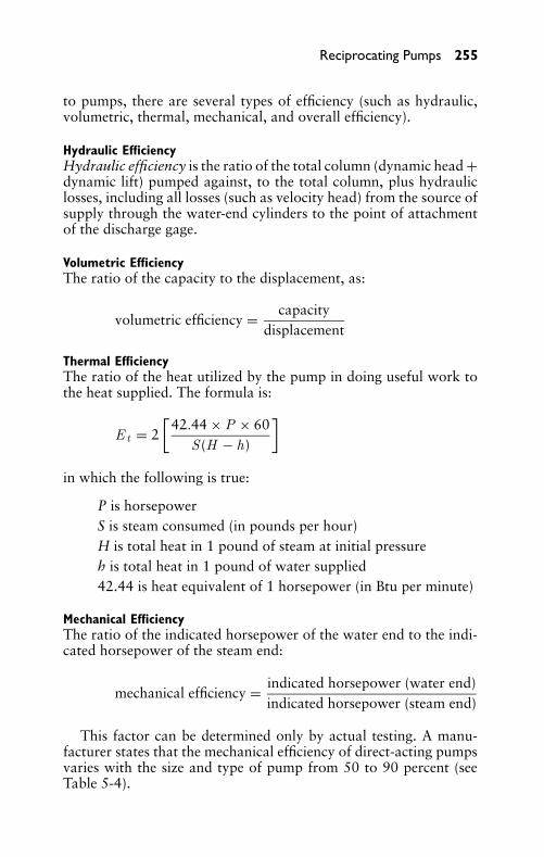
P1: FCH
GB098-05 GB098-Miller September 13, 2004 17:54 Char Count= 0
Reciprocating Pumps 255
to pumps, there are several types of efficiency (such as hydraulic,volumetric, thermal, mechanical, and overall efficiency).
Hydraulic EfficiencyHydraulic efficiency is the ratio of the total column (dynamic head +dynamic lift) pumped against, to the total column, plus hydrauliclosses, including all losses (such as velocity head) from the source ofsupply through the water-end cylinders to the point of attachmentof the discharge gage.
Volumetric EfficiencyThe ratio of the capacity to the displacement, as:
volumetric efficiency = capacitydisplacement
Thermal EfficiencyThe ratio of the heat utilized by the pump in doing useful work tothe heat supplied. The formula is:
E t = 2[
42.44 × P × 60S (H − h)
]
in which the following is true:
P is horsepowerS is steam consumed (in pounds per hour)H is total heat in 1 pound of steam at initial pressureh is total heat in 1 pound of water supplied42.44 is heat equivalent of 1 horsepower (in Btu per minute)
Mechanical EfficiencyThe ratio of the indicated horsepower of the water end to the indi-cated horsepower of the steam end:
mechanical efficiency = indicated horsepower (water end)indicated horsepower (steam end)
This factor can be determined only by actual testing. A manu-facturer states that the mechanical efficiency of direct-acting pumpsvaries with the size and type of pump from 50 to 90 percent (seeTable 5-4).
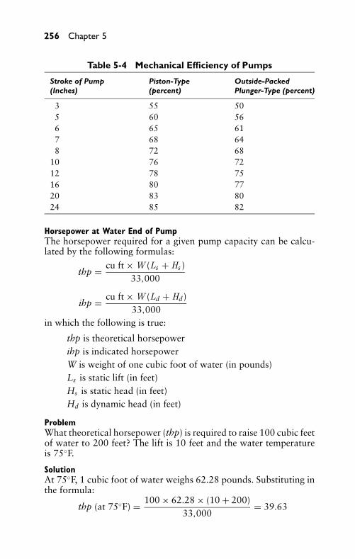
P1: FCH
GB098-05 GB098-Miller September 13, 2004 17:54 Char Count= 0
256 Chapter 5
Table 5-4 Mechanical Efficiency of Pumps
Stroke of Pump Piston-Type Outside-Packed(Inches) (percent) Plunger-Type (percent)
3 55 505 60 566 65 617 68 648 72 68
10 76 7212 78 7516 80 7720 83 8024 85 82
Horsepower at Water End of PumpThe horsepower required for a given pump capacity can be calcu-lated by the following formulas:
thp = cu ft × W (Ls + Hs )33,000
ihp = cu ft × W (Ld + Hd)33,000
in which the following is true:
thp is theoretical horsepowerihp is indicated horsepowerW is weight of one cubic foot of water (in pounds)Ls is static lift (in feet)Hs is static head (in feet)Hd is dynamic head (in feet)
ProblemWhat theoretical horsepower (thp) is required to raise 100 cubic feetof water to 200 feet? The lift is 10 feet and the water temperatureis 75◦F.
SolutionAt 75◦F, 1 cubic foot of water weighs 62.28 pounds. Substituting inthe formula:
thp (at 75◦F) = 100 × 62.28 × (10 + 200)33,000
= 39.63
P1: FCH
GB098-05 GB098-Miller September 13, 2004 17:54 Char Count= 0
Reciprocating Pumps 257
At 35◦F (cold weather), the weight of 1 cubic foot of water in-creases to 62.42. The horsepower increases in proportion to theratio of the two weights, as follows:
thp (at 35◦F) = 39.63 × 62.4262.28
= 39.7
In comparing the preceding equations, it may be noted that tem-perature causes only a slight difference in the results. Thus, the tem-perature factor can be disregarded for most calculations, and thecommon weight value of 62.4 pounds per cubic foot of water canbe used. Table 5-5 shows the theoretical horsepower required toraise water to various heights.
Water Supply PumpsCareful consideration must be given to the selection of pumps forwater supply purposes, for each pump, application will differ, notonly in capacity requirements, but also in the pressure against whichthe pump will have to operate. For example, a 1/2-inch hose withnozzle is to be used for sprinkling water, will be consumed at the rateof 200 gallons per hour. To permit use of water for other purposesat the same time, it is necessary to have a pump capacity in excessof 200 gallons per hour. Where 1/2-inch hose with nozzle is to beused, it is necessary to have a pump with a capacity of at least 220gallons per hour. In determining the desired pump capacity, even forordinary requirements, it is advisable to select a size large enoughso that the pump will not run more than a few hours per day.
Typical Water-Supply PumpsAutomatic and semiautomatic pump installations for water supplypurposes generally employ the following four types of pumps (allconforming to the same general principles):
� Reciprocating or plunger� Rotary� Centrifugal� Jet or ejector
The ejector pump gets its name from the introduction of a jetstream attached to the centrifugal or reciprocating type of pump.Table 5-6 provides a brief tabulation of the characteristics of thevarious types of pumps. For convenience, the pumps are classifiedaccording to speed, suction lift, and practical pressure head.
Reciprocating pumps will deliver water in quantities proportionalto the number of strokes and the length and size of the cylinder. Theyare adapted to a wide range of speeds, and to practically any depth
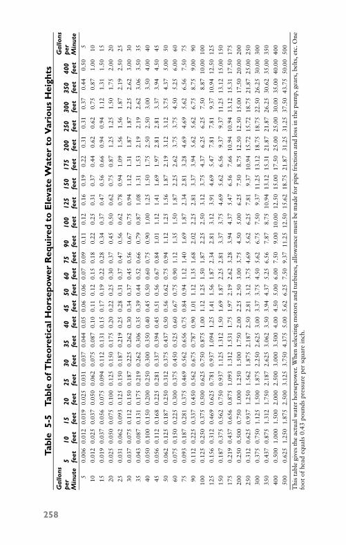
P1: FCH
GB098-05 GB098-Miller September 13, 2004 17:54 Char Count= 0
Tabl
e5-
5Ta
ble
ofT
heo
reti
calH
ors
epow
erR
equi
red
toE
leva
teW
ater
toV
ario
usH
eigh
tsG
allo
nsG
allo
nsp
er5
1015
2025
3035
4045
5060
7590
100
125
150
175
200
250
300
350
400
per
Min
ute
feet
feet
feet
feet
feet
feet
feet
feet
feet
feet
feet
feet
feet
feet
feet
feet
feet
feet
feet
feet
feet
feet
Min
ute
50.
006
0.01
20.
019
0.02
50.
031
0.03
70.
044
0.05
0.06
0.06
0.07
0.09
0.11
0.12
0.16
0.19
0.22
0.31
0.31
0.37
0.44
0.50
5
100.
012
0.02
50.
037
0.05
00.
062
0.07
50.
087
0.10
0.11
0.12
0.15
0.18
0.22
0.25
0.31
0.37
0.44
0.62
0.62
0.75
0.87
1.00
10
150.
019
0.03
70.
056
0.07
50.
094
0.11
20.
131
0.15
0.17
0.19
0.22
0.28
0.34
0.37
0.47
0.56
0.66
0.94
0.94
1.12
1.31
1.50
15
200.
025
0.05
00.
075
0.10
00.
125
0.15
00.
175
0.20
0.22
0.25
0.30
0.37
0.45
0.50
0.62
0.75
0.87
1.25
1.25
1.50
1.75
2.00
20
250.
031
0.06
20.
093
0.12
50.
150
0.18
70.
219
0.25
0.28
0.31
0.37
0.47
0.56
0.62
0.78
0.94
1.09
1.56
1.56
1.87
2.19
2.50
25
300.
037
0.07
50.
112
0.15
00.
187
0.22
50.
262
0.30
0.34
0.37
0.45
0.56
0.67
0.75
0.94
1.12
1.31
1.87
1.87
2.25
2.62
3.00
30
350.
043
0.08
70.
131
0.17
50.
219
0.26
20.
306
0.35
0.39
0.44
0.52
0.66
0.79
0.87
1.08
1.31
1.53
2.19
2.19
2.62
3.06
3.50
35
400.
050
0.10
00.
150
0.20
00.
250
0.30
00.
350
0.40
0.45
0.50
0.60
0.75
0.90
1.00
1.25
1.50
1.75
2.50
2.50
3.00
3.50
4.00
40
450.
056
0.11
20.
168
0.22
50.
281
0.33
70.
394
0.45
0.51
0.56
0.67
0.84
1.01
1.12
1.41
1.69
1.97
2.81
2.81
3.37
3.94
4.50
45
500.
062
0.12
50.
187
0.25
00.
312
0.37
50.
437
0.50
0.56
0.62
0.75
0.94
1.12
1.25
1.56
1.87
2.19
3.12
3.12
3.75
4.37
5.00
50
600.
075
0.15
00.
225
0.30
00.
375
0.45
00.
525
0.60
0.67
0.75
0.90
1.12
1.35
1.50
1.87
2.25
2.62
3.75
3.75
4.50
5.25
6.00
60
750.
093
0.18
70.
281
0.37
50.
469
0.56
20.
656
0.75
0.84
0.94
1.12
1.40
1.69
1.87
2.34
2.81
3.28
4.69
4.69
5.62
6.56
7.50
75
900.
112
0.22
50.
337
0.45
00.
562
0.67
50.
787
0.90
1.01
1.12
1.35
1.68
2.02
2.25
2.81
3.37
3.94
5.62
5.62
6.75
8.75
9.00
90
100
0.12
50.
250
0.37
50.
500
0.62
50.
750
0.87
51.
001.
121.
251.
501.
872.
252.
503.
123.
754.
376.
256.
257.
508.
8710
.00
100
125
0.15
60.
312
0.46
90.
625
0.78
10.
937
1.09
41.
251.
411.
561.
872.
342.
813.
123.
914.
695.
477.
817.
819.
3710
.94
12.5
012
5
150
0.18
70.
375
0.56
20.
750
0.93
71.
125
1.31
21.
501.
691.
872.
252.
813.
373.
754.
695.
626.
569.
379.
3711
.25
13.1
215
.00
150
175
0.21
90.
437
0.65
60.
875
1.09
31.
312
1.53
11.
751.
972.
192.
623.
283.
944.
375.
476.
567.
6610
.94
10.9
413
.12
15.3
117
.50
175
200
0.25
00.
500
0.75
01.
000
1.25
01.
500
1.75
02.
002.
252.
503.
003.
754.
505.
006.
257.
508.
7512
.50
12.5
015
.00
17.5
020
.00
200
250
0.31
20.
625
0.93
71.
250
1.56
21.
875
2.18
72.
502.
813.
123.
754.
695.
626.
257.
819.
3710
.94
15.7
215
.72
18.7
521
.87
25.0
025
0
300
0.37
50.
750
1.12
51.
500
1.87
52.
250
2.62
53.
003.
373.
754.
505.
626.
757.
509.
3711
.25
13.1
218
.75
18.7
522
.50
26.2
530
.00
300
350
0.43
70.
875
1.31
21.
750
2.18
72.
625
3.06
23.
503.
944.
375.
256.
567.
878.
7510
.94
13.1
215
.31
21.8
721
.87
26.2
530
.62
35.0
035
0
400
0.50
01.
000
1.50
02.
000
2.50
03.
000
3.50
04.
004.
505.
006.
007.
509.
0010
.00
12.5
015
.00
17.5
025
.00
25.0
030
.00
35.0
040
.00
400
500
0.62
51.
250
1.87
52.
500
3.12
53.
750
4.37
55.
005.
626.
257.
509.
3711
.25
12.5
015
.62
18.7
521
.87
31.2
531
.25
37.5
043
.75
50.0
050
0
Thi
sta
ble
give
sth
eac
tual
wat
erho
rsep
ower
.Whe
nse
lect
ing
mot
ors
and
turb
ines
,allo
wan
cem
ustb
em
ade
for
pipe
fric
tion
and
loss
inth
epu
mp,
gear
s,be
lts,
etc.
One
foot
ofhe
adeq
uals
0.43
poun
dspr
essu
repe
rsq
uare
inch
.
258
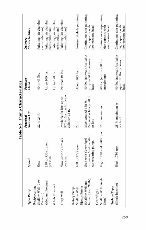
P1: FCH
GB098-05 GB098-Miller September 13, 2004 17:54 Char Count= 0
Tabl
e5-
6P
ump
Cha
ract
eris
tics
Pra
ctic
alP
ress
ure
Del
iver
yTy
pe
Pum
pSp
eed
Suct
ion
Lift
Hea
dC
hara
cter
isti
cs
Rec
ipro
cati
ng:
Shal
low
Wel
l(L
owPr
essu
re)
Slow
22to
25ft
.40
to43
lbs.
Puls
atin
g(a
irch
ambe
rev
ens
puls
atio
ns)
(Med
ium
Pres
sure
)25
0to
550
stro
kes
per
min
.U
pto
100
lbs.
Puls
atin
g(a
irch
ambe
rev
ens
puls
atio
ns)
(Hig
hPr
essu
re)
Up
to35
0lb
s.Pu
lsat
ing
(air
cham
ber
even
spu
lsat
ions
)D
eep
Wel
lSl
ow30
to52
stro
kes
per
min
.A
vaila
ble
for
lifts
upto
875
ft.S
ucti
onlif
tbe
low
cylin
der
22ft
.
Nor
mal
40lb
s.Pu
lsat
ing
(air
cham
ber
even
spu
lsat
ions
)
Rot
ary
Pum
p:Sh
allo
wW
ell
400
to17
25rp
m22
ft.
Abo
ut10
0lb
s.Po
siti
ve(s
light
lypu
lsat
ing)
Eje
ctor
Pum
p:(S
hallo
wW
ella
ndlim
ited
Dee
pW
ells
)U
sed
wit
hC
entr
ifug
al-
turb
ine
orSh
allo
wW
ell
reci
proc
atin
gpu
mp.
Max
.aro
und
120
ft.
Prac
tica
lat
lifts
of80
ft.
orle
ss
40lb
s.(n
orm
al)
Ava
ilabl
eat
upto
70lb
spr
essu
rehe
ad
Con
tinu
ous
non-
puls
atin
g,hi
ghca
paci
tyw
ith
low
-pre
ssur
ehe
adC
entr
ifug
al:
Shal
low
Wel
l(Si
ngle
Stag
e)H
igh,
1750
and
3600
rpm
15ft
.max
imum
40lb
s.(n
orm
al)
70lb
s(m
axim
um)
Con
tinu
ous
non-
puls
atin
g,hi
ghca
paci
tyw
ith
low
-pre
ssur
ehe
adT
urbi
neT
ype:
(Sin
gle
Impe
ller)
Hig
h,17
50rp
m28
ft.m
axim
umat
sea
leve
l40
lbs.
(nor
mal
)A
vaila
ble
upto
100
lbs.
pres
sure
head
Con
tinu
ous
non-
puls
atin
g,hi
ghca
paci
tyw
ith
low
-pre
ssur
ehe
ad
259
P1: FCH
GB098-05 GB098-Miller September 13, 2004 17:54 Char Count= 0
260 Chapter 5
of well. Since reciprocating pumps are positive in operation, theyshould be fitted with automatic relief valves to prevent rupture ofpipes or other damage should power be applied against abnormalpressure.
Centrifugal pumps are somewhat critical as far as speed is con-cerned. They should be used only where power can be applied ata reasonably constant speed. The vertical type centrifugal pump isused in deep wells. They are usually driven through shafting by ver-tical motors mounted at the top of the well.
Turbine pumps (as used in domestic water systems) are self-priming. Their smooth operation makes them suitable for appli-cations where noise and vibrations must be kept to a minimum.
Ejector pumps operate quietly, and neither the deep well nor theshallow well type need be mounted over the well.
SummaryA reciprocating pump has a to-and-fro motion. Its motion is back-ward and forward (or upward and downward) as distinguished fromthe circular motion of centrifugal and rotary pumps. A piston orplunger differentiates the reciprocating pump from a centrifugal orrotary pump. In the reciprocating pump, the reciprocating motionof the wrist pin is converted to circular motion by means of a con-necting link or connecting rod.
A lift pump is a single-acting pump. It consists of an open cylinderand a discharge or bucket-type valve. It lifts the water, rather thanforces it. A force pump is a single-acting or a double-acting pump.
After the lift pump has been primed, its working cycle is com-pleted in two strokes of the piston: a downward or transfer stroke,and the upward stroke (which is an intake and discharge stroke,because water enters the cylinder as the preceding charge of wateris being discharged).
The force pump is actually an extension of the lift pump. It liftsand forces the water against an external pressure. The basic operat-ing principle of the force pump is that it forces water above the levelattained by the atmospheric pressure range, as distinguished fromthe lift pump, which elevates the water to flow from a spout.
In a single-acting force pump, the water is forced from the cylin-der by means of a piston or plunger working against a pressure thatcorresponds to the head or elevation above the inlet valve to whichthe water is pumped. The working cycle is completed in two strokes:an upward (intake) stroke and a downward (discharge) stroke. Dur-ing the intake stroke, the vacuum that is created enables atmosphericpressure to force the water into the cylinder. During the discharge
P1: FCH
GB098-05 GB098-Miller September 13, 2004 17:54 Char Count= 0
Reciprocating Pumps 261
stroke, the plunger displaces (forces open) the discharge valve, andthe water flows from the cylinder against the pressure resulting fromthe dynamic head.
In a double-acting force pump, the piston discharges water fromone side of the piston while drawing water into the cylinder onthe other side—without a transfer stroke. Thus, water is dischargedon each stroke, rather than on alternate strokes, as in the single-acting pumps. Therefore, the capacity of a double-acting pump canbe twice that of a single-acting pump having an identical cylinderdisplacement.
Reciprocating piston pumps having a large capacity are used inmany industrial applications. They are designed with three, five,seven, or nine plungers. The plunger-type pumps are widely used inindustry to accomplish medium- to high-pressure chemical feeding.These pumps are readily adapted to applications requiring continu-ous, intermittent, or flow-responsive feeding.
Theoretical lift and actual lift are quite different. Actual lift is alesser value than theoretical lift; it is limited by factors, such as watertemperature, decreased air pressure at higher elevations, frictionalresistance (through pipes, fittings, and passages), and leakage.
The nominal size of the discharge pipe is usually smaller than thatof the inlet pipe. The required size of the discharge line is dependenton its length, number of elbows in the line, and other conditionsthat tend to resist the flow of water.
The total load on a pump is not equal to the head alone. Thelift must also be considered. The pump must raise the water fromthe surface level in the wall to the surface level in the tank. This istermed total static column. The formula for total static column is:
Cs = Ls + Hs
When all resistances to flow are considered, the total load be-comes total dynamic column, and the formula is:
Cd = Ld + Hd
The volume of fluid that is displaced by a piston or plunger ina single stroke is called displacement. Displacement is expressedin cubic inches per stroke, cubic inches per minute, or gallons perminute. To determine piston displacement in cubic inches per stroke,multiply the effective area of the piston or plunger by the length ofthe stroke.
The total distance, in feet, traveled by a piston (or plunger) in 1minute is referred to as the piston speed. This is a factor in calculat-ing displacement. In a simplex single-acting pump, only one stroke
P1: FCH
GB098-05 GB098-Miller September 13, 2004 17:54 Char Count= 0
262 Chapter 5
per revolution occurs. In the double-acting pump, two dischargingstrokes per revolution occur.
In a pump, slip is generally expressed as a percentage of displace-ment. Pumps may fall short of the water previously designed tohandle. The amount or the volume of water (delivered per stroke)that falls short of the pump’s displacement that is being used in theproblem. The percentage of slip varies from 2 to 10 percent. It de-pends on the type of pump (piston or plunger). The condition ofthe pump also figures into the slip variation. So does the pressureagainst which the pump is working. When the discharge volumeis greater than the displacement, the condition is called negativeslip.
The capacity of a pump is the actual volume of water or fluiddelivered. It is usually stated in terms of gallons per stroke or gallonsper minute when discharging at a given speed. To calculate capacity,multiply the area of the piston (square inches) by the length of thestroke (inches) and by the number of delivery strokes per minute.Divide the product by 1728 (to obtain theoretical capacity, in cubicfeet) or by 231 (to obtain theoretical capacity, in gallons).
Efficiency is the ratio of the useful work performed by a primemover to the energy expended in producing it. There are severaltypes of efficiency in regard to pumps (such as hydraulic, volumetric,thermal, mechanical, and overall efficiency).
Review Questions1. How does a reciprocating pump differ from a centrifugal or
rotary pump?2. How does the basic operation of a lift pump differ from that
of a force pump?3. What is the chief difference in the working cycles of the single-
acting force pump and the double-acting force pump?4. Compare the capacities of single-acting and double-acting
force pumps having identical cylinder displacements.5. What are the disadvantages of the inside-packed double-acting
plunger-type force pump?6. Describe the working cycle of the self-priming reciprocating
pump.7. What types of industrial applications use reciprocating piston
pumps?8. Compare theoretical lift and actual lift.
P1: FCH
GB098-05 GB098-Miller September 13, 2004 17:54 Char Count= 0
Reciprocating Pumps 263
9. Why is the nominal size of the discharge pipe usually smallerthan the nominal size of the intake line?
10. Why is the total load on a pump not equal to just the headalone?
11. What is meant by displacement, and how is it expressed?12. What is meant by slip, and how is it expressed?13. How is capacity of a pump calculated?14. What are three moving elements necessary for operation of a
reciprocating pump?15. What is the difference between a piston and a plunger?16. List the four strokes of a single-acting lift pump.17. List the four strokes of a single-acting force pump with a
bucket-type valve in the piston.18. How many plungers can reciprocating pumps have?19. What is the lift at sea level of water at 120◦F?20. What is the term used to indicate the volume of fluid that
is displaced by the piston or plunger in a single stroke in areciprocating pump?
21. Define hydraulic efficiency.22. Define volumetric efficiency.23. Define thermal efficiency.24. Define mechanical efficiency.25. How much horsepower would it take to lift 40 gallons of water
to a height of 10 feet?

P1: FCH
GB098-05 GB098-Miller September 13, 2004 17:54 Char Count= 0
264
P1: FCH
GB098-06 GB098-Miller September 13, 2004 17:58 Char Count= 0
Chapter 6Special-Service PumpsPump selection should be based on a thorough understanding ofthe characteristics and fundamental principles of the basic types ofpumps (such as centrifugal, rotary, reciprocating, and so on), whichhave been discussed in preceding chapters. The operating principlesand various design characteristics or features adapt these pumps tospecialized or unusual service conditions. In some instances, pumpshave been designed especially for a given type of job or servicecondition.
Many of the pumps that have been introduced are specifically de-signed for special types of service or operating conditions. Some ofthese special types of pumps are used by fire departments, railroads,automobiles, diesel engines, contractors, mines, drainage, hydro-static transmissions, machine tools, and numerous other applica-tions throughout industry. Liquids requiring a special type of pumpare pure water, sewage, paper stock, oil, milk, chemicals, magma,and various types of thick liquids.
Service PumpsSimplex or duplex reciprocating piston-type pumps are well-adaptedfor the service requirements found in tanneries, sugar refineries,bleacheries, and so on. The duplex high-pressure reciprocating pis-ton pump shown in Figure 6-1 is adapted for high-pressure serviceon water supply systems in country clubs, dairies, industrial plants,and so on. Two double-acting pistons actually provide four strokesper revolution, which produces a constant and even flow of liquidthrough the pump. This pump can handle either cold or hot water attemperatures up to 200◦F. This type of pump is capable of capacitiesranging from 295 to 1080 gallons per hour, and working pressuresranging from 150 to 300 psi.
The general-purpose rotary gear-type pump (see Figure 6-2) is de-signed to handle either thick or thin liquids. It can operate smoothlyin either direction of rotation with equal efficiency. These pumps canhandle heavy, viscous materials (such as roofing materials or print-ing inks), as well as fuel oils, gasoline, and similar thin liquids. Thepump shown is capable of capacities ranging from 40 to 600 gallonsper minute and pressures to 100 psi.
The rotary gear-type pump shown in Figure 6-3 is adaptable to awide range of jobs, such as pressure lubrication, hydraulic service,fuel supply, or general transfer work, which includes pumping cleanliquids. The bearings are lubricated by the liquid being pumped.
265
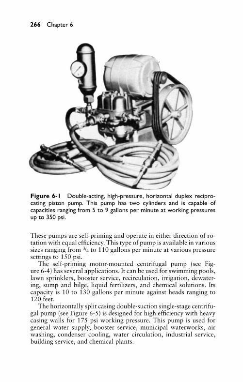
P1: FCH
GB098-06 GB098-Miller September 13, 2004 17:58 Char Count= 0
266 Chapter 6
Figure 6-1 Double-acting, high-pressure, horizontal duplex recipro-cating piston pump. This pump has two cylinders and is capable ofcapacities ranging from 5 to 9 gallons per minute at working pressuresup to 350 psi.
These pumps are self-priming and operate in either direction of ro-tation with equal efficiency. This type of pump is available in varioussizes ranging from 3/4 to 110 gallons per minute at various pressuresettings to 150 psi.
The self-priming motor-mounted centrifugal pump (see Fig-ure 6-4) has several applications. It can be used for swimming pools,lawn sprinklers, booster service, recirculation, irrigation, dewater-ing, sump and bilge, liquid fertilizers, and chemical solutions. Itscapacity is 10 to 130 gallons per minute against heads ranging to120 feet.
The horizontally split casing double-suction single-stage centrifu-gal pump (see Figure 6-5) is designed for high efficiency with heavycasing walls for 175 psi working pressure. This pump is used forgeneral water supply, booster service, municipal waterworks, airwashing, condenser cooling, water circulation, industrial service,building service, and chemical plants.
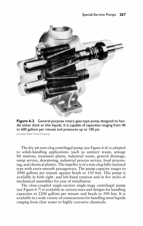
P1: FCH
GB098-06 GB098-Miller September 13, 2004 17:58 Char Count= 0
Special-Service Pumps 267
Figure 6-2 General-purpose rotary gear-type pump designed to han-dle either thick or thin liquids. It is capable of capacities ranging from 40to 600 gallons per minute and pressures up to 100 psi.(Courtesy Roper Pump Company)
The dry-pit non-clog centrifugal pump (see Figure 6-6) is adaptedto solids-handling applications (such as sanitary waste, sewagelift stations, treatment plants, industrial waste, general drainage,sump service, dewatering, industrial process service, food process-ing, and chemical plants). The impeller is of a non-clog fully enclosedtype with extra-smooth passageways. The pump capacity ranges to3000 gallons per minute against heads to 150 feet. This pump isavailable in both right- and left-hand rotation and in five styles ofmechanical assemblies for ease of installation.
The close-coupled single-suction single-stage centrifugal pump(see Figure 6-7) is available in various sizes and designs for handlingcapacities to 2200 gallons per minute and heads to 500 feet. It isavailable in a wide variety of constructions for handling most liquidsranging from clear water to highly corrosive chemicals.
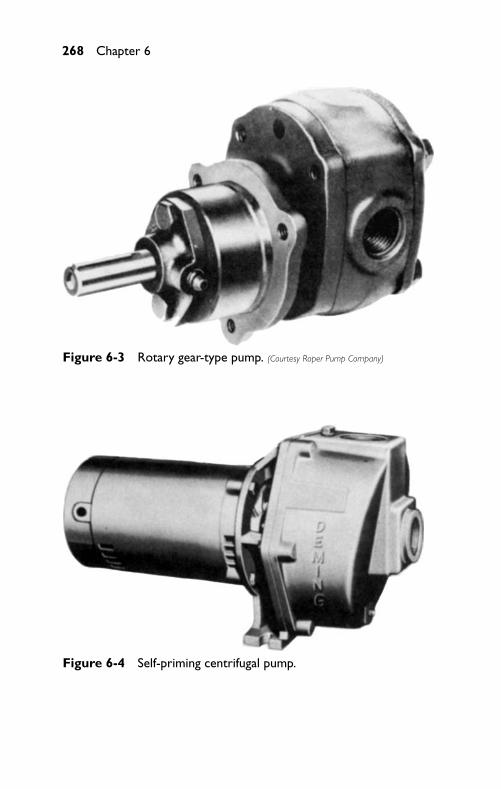
P1: FCH
GB098-06 GB098-Miller September 13, 2004 17:58 Char Count= 0
268 Chapter 6
Figure 6-3 Rotary gear-type pump. (Courtesy Roper Pump Company)
Figure 6-4 Self-priming centrifugal pump.
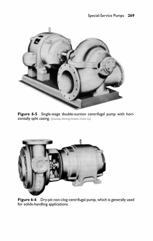
P1: FCH
GB098-06 GB098-Miller September 13, 2004 17:58 Char Count= 0
Special-Service Pumps 269
Figure 6-5 Single-stage double-suction centrifugal pump with hori-zontally split casing. (Courtesy Deming Division, Crane Co.)
Figure 6-6 Dry-pit non-clog centrifugal pump, which is generally usedfor solids-handling applications.
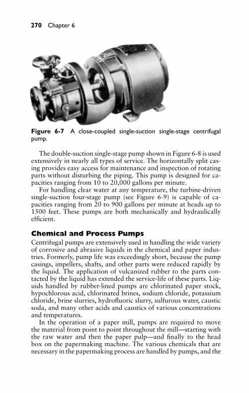
P1: FCH
GB098-06 GB098-Miller September 13, 2004 17:58 Char Count= 0
270 Chapter 6
Figure 6-7 A close-coupled single-suction single-stage centrifugalpump.
The double-suction single-stage pump shown in Figure 6-8 is usedextensively in nearly all types of service. The horizontally split cas-ing provides easy access for maintenance and inspection of rotatingparts without disturbing the piping. This pump is designed for ca-pacities ranging from 10 to 20,000 gallons per minute.
For handling clear water at any temperature, the turbine-drivensingle-suction four-stage pump (see Figure 6-9) is capable of ca-pacities ranging from 20 to 900 gallons per minute at heads up to1500 feet. These pumps are both mechanically and hydraulicallyefficient.
Chemical and Process PumpsCentrifugal pumps are extensively used in handling the wide varietyof corrosive and abrasive liquids in the chemical and paper indus-tries. Formerly, pump life was exceedingly short, because the pumpcasings, impellers, shafts, and other parts were reduced rapidly bythe liquid. The application of vulcanized rubber to the parts con-tacted by the liquid has extended the service-life of these parts. Liq-uids handled by rubber-lined pumps are chlorinated paper stock,hypochlorous acid, chlorinated brines, sodium chloride, potassiumchloride, brine slurries, hydrofluoric slurry, sulfurous water, causticsoda, and many other acids and caustics of various concentrationsand temperatures.
In the operation of a paper mill, pumps are required to movethe material from point to point throughout the mill—starting withthe raw water and then the paper pulp—and finally to the headbox on the papermaking machine. The various chemicals that arenecessary in the papermaking process are handled by pumps, and the
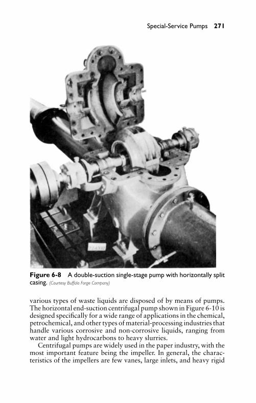
P1: FCH
GB098-06 GB098-Miller September 13, 2004 17:58 Char Count= 0
Special-Service Pumps 271
Figure 6-8 A double-suction single-stage pump with horizontally splitcasing. (Courtesy Buffalo Forge Company)
various types of waste liquids are disposed of by means of pumps.The horizontal end-suction centrifugal pump shown in Figure 6-10 isdesigned specifically for a wide range of applications in the chemical,petrochemical, and other types of material-processing industries thathandle various corrosive and non-corrosive liquids, ranging fromwater and light hydrocarbons to heavy slurries.
Centrifugal pumps are widely used in the paper industry, with themost important feature being the impeller. In general, the charac-teristics of the impellers are few vanes, large inlets, and heavy rigid
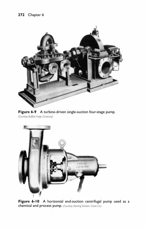
P1: FCH
GB098-06 GB098-Miller September 13, 2004 17:58 Char Count= 0
272 Chapter 6
Figure 6-9 A turbine-driven single-suction four-stage pump.(Courtesy Buffalo Forge Company)
Figure 6-10 A horizontal end-suction centrifugal pump used as achemical and process pump. (Courtesy Deming Division, Crane Co.)
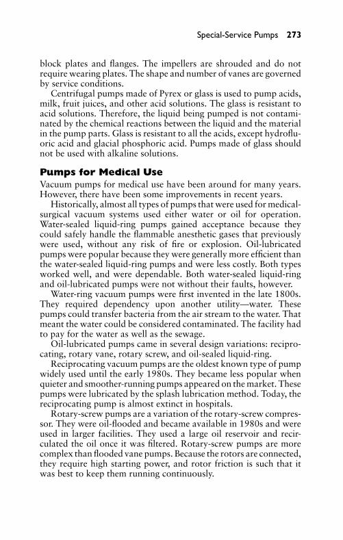
P1: FCH
GB098-06 GB098-Miller September 13, 2004 17:58 Char Count= 0
Special-Service Pumps 273
block plates and flanges. The impellers are shrouded and do notrequire wearing plates. The shape and number of vanes are governedby service conditions.
Centrifugal pumps made of Pyrex or glass is used to pump acids,milk, fruit juices, and other acid solutions. The glass is resistant toacid solutions. Therefore, the liquid being pumped is not contami-nated by the chemical reactions between the liquid and the materialin the pump parts. Glass is resistant to all the acids, except hydroflu-oric acid and glacial phosphoric acid. Pumps made of glass shouldnot be used with alkaline solutions.
Pumps for Medical UseVacuum pumps for medical use have been around for many years.However, there have been some improvements in recent years.
Historically, almost all types of pumps that were used for medical-surgical vacuum systems used either water or oil for operation.Water-sealed liquid-ring pumps gained acceptance because theycould safely handle the flammable anesthetic gases that previouslywere used, without any risk of fire or explosion. Oil-lubricatedpumps were popular because they were generally more efficient thanthe water-sealed liquid-ring pumps and were less costly. Both typesworked well, and were dependable. Both water-sealed liquid-ringand oil-lubricated pumps were not without their faults, however.
Water-ring vacuum pumps were first invented in the late 1800s.They required dependency upon another utility—water. Thesepumps could transfer bacteria from the air stream to the water. Thatmeant the water could be considered contaminated. The facility hadto pay for the water as well as the sewage.
Oil-lubricated pumps came in several design variations: recipro-cating, rotary vane, rotary screw, and oil-sealed liquid-ring.
Reciprocating vacuum pumps are the oldest known type of pumpwidely used until the early 1980s. They became less popular whenquieter and smoother-running pumps appeared on the market. Thesepumps were lubricated by the splash lubrication method. Today, thereciprocating pump is almost extinct in hospitals.
Rotary-screw pumps are a variation of the rotary-screw compres-sor. They were oil-flooded and became available in 1980s and wereused in larger facilities. They used a large oil reservoir and recir-culated the oil once it was filtered. Rotary-screw pumps are morecomplex than flooded vane pumps. Because the rotors are connected,they require high starting power, and rotor friction is such that itwas best to keep them running continuously.
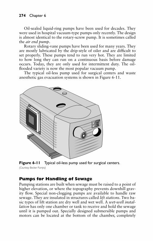
P1: FCH
GB098-06 GB098-Miller September 13, 2004 17:58 Char Count= 0
274 Chapter 6
Oil-sealed liquid-ring pumps have been used for decades. Theywere used in hospital vacuum-type pumps only recently. The designis almost identical to the rotary-screw pump. It is sometimes calledthe air end pump.
Rotary sliding-vane pumps have been used for many years. Theyare mostly lubricated by the drip-style of oiler and are difficult toset properly. These pumps tend to run very hot. They are limitedto how long they can run on a continuous basis before damageoccurs. Today, they are only used for intermittent duty. The oil-flooded variety is now the most popular vacuum pump.
The typical oil-less pump used for surgical centers and wasteanesthetic gas evacuation systems is shown in Figure 6-11.
123
456
789
10
Figure 6-11 Typical oil-less pump used for surgical centers.(Courtesy Becker Pumps)
Pumps for Handling of SewagePumping stations are built when sewage must be raised to a point ofhigher elevation, or where the topography prevents downhill grav-ity flow. Special non-clogging pumps are available to handle rawsewage. They are insulated in structures called lift stations. Two ba-sic types of lift station are dry well and wet well. A wet-well instal-lation has only one chamber or tank to receive and hold the sewageuntil it is pumped out. Specially designed submersible pumps andmotors can be located at the bottom of the chamber, completely
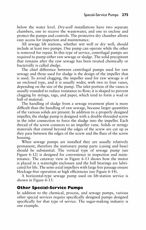
P1: FCH
GB098-06 GB098-Miller September 13, 2004 17:58 Char Count= 0
Special-Service Pumps 275
below the water level. Dry-well installations have two separatechambers, one to receive the wastewater, and one to enclose andprotect the pumps and controls. The protective dry chamber allowseasy access for inspection and maintenance.
All sewage lift stations, whether wet well or dry well, shouldinclude at least two pumps. One pump can operate while the otheris removed for repair. In this type of service, centrifugal pumps arerequired to pump either raw sewage or sludge. The solid precipitantthat remains after the raw sewage has been treated chemically orbacterially is called sludge.
The chief difference between centrifugal pumps used for rawsewage and those used for sludge is the design of the impeller thatis used. To avoid clogging, the impeller used for raw sewage is ofan enclosed type, and it is usually wider, with two to four vanes,depending on the size of the pump. The inlet portion of the vanes isusually rounded to reduce resistance to flow; it is shaped to preventclogging by strings, rags, and paper, which tend to form a wad orball of material.
The handling of sludge from a sewage treatment plant is moredifficult than the handling of raw sewage, because larger quantitiesof the various solids are present. In addition to a properly designedimpeller, the sludge pump is designed with a double-threaded screwin the inlet connection to force the sludge into the impeller. Eachthread of the screw connects to an impeller vane. Solids or stringymaterials that extend beyond the edges of the screw are cut up asthey pass between the edges of the screw and the flues of the screwhousing.
When sewage pumps are installed they are usually relativelypermanent, therefore the stationary pump parts (casing and base)should be substantial. The vertical type of sewage pump (seeFigure 6-12) is designed for convenience in inspection and main-tenance. The cutaway view in Figure 6-13 shows how the motoris placed in a watertight enclosure and the ball bearings are lubri-cated for life. The semi-axial impellers with large free passage ensureblockage-free operation at high efficiencies (see Figure 6-14).
A horizontal-type sewage pump used on lift-station service isshown in Figure 6-15.
Other Special-Service PumpsIn addition to the chemical, process, and sewage pumps, variousother special services require specifically designed pumps designedspecifically for that type of service. The sugar-making industry isone example.
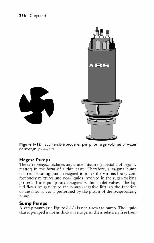
P1: FCH
GB098-06 GB098-Miller September 13, 2004 17:58 Char Count= 0
276 Chapter 6
Figure 6-12 Submersible propeller pump for large volumes of wateror sewage. (Courtesy ABS)
Magma PumpsThe term magma includes any crude mixture (especially of organicmatter) in the form of a thin paste. Therefore, a magma pumpis a reciprocating pump designed to move the various heavy con-fectionery mixtures and non-liquids involved in the sugar-makingprocess. These pumps are designed without inlet valves—the liq-uid flows by gravity to the pump (negative lift), so the functionof the inlet valves is performed by the piston of the reciprocatingpump.
Sump PumpsA sump pump (see Figure 6-16) is not a sewage pump. The liquidthat is pumped is not as thick as sewage, and it is relatively free from
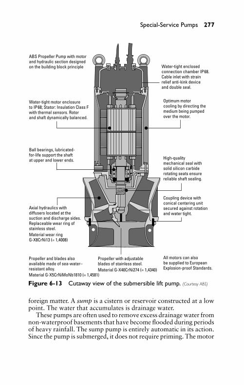
P1: FCH
GB098-06 GB098-Miller September 13, 2004 17:58 Char Count= 0
Special-Service Pumps 277
ABS Propeller Pump with motorand hydraulic section designedon the building block principle
Water-tight motor enclosureto IP68; Stator: Insulation Class Fwith thermal sensors. Rotorand shaft dynamically balanced.
Ball bearings, lubricated-for-life support the shaftat upper and lower ends.
Axial hydraulics withdiffusers located at thesuction and discharge sides.Replaceable wear ring ofstainless steel.Material wear ringG-X8CrNi13 (= 1,4008)
Propeller and blades alsoavailable made of sea-water–resistant alloy.
Propeller with adjustableblades of stainless steel.
Material G-X5CrNiMoNb1810 (= 1,4581)Material G-X40CrNi274 (= 1,4340)
All motors can alsobe supplied to EuropeanExplosion-proof Standards.
Coupling device withconical centering unitsecured against rotationand water tight.
High-qualitymechanical seal withsolid silicon carbiderotating seats ensurereliable shaft sealing.
Optimum motorcooling by directing themedium being pumpedover the motor.
Water-tight enclosedconnection chamber IP68.Cable inlet with strainrelief anti-kink deviceand double seal.
Figure 6-13 Cutaway view of the submersible lift pump. (Courtesy ABS)
foreign matter. A sump is a cistern or reservoir constructed at a lowpoint. The water that accumulates is drainage water.
These pumps are often used to remove excess drainage water fromnon-waterproof basements that have become flooded during periodsof heavy rainfall. The sump pump is entirely automatic in its action.Since the pump is submerged, it does not require priming. The motor
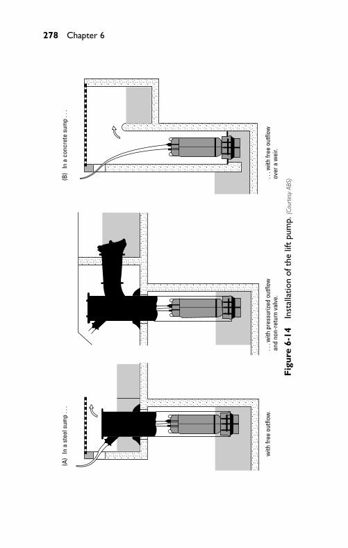
P1: FCH
GB098-06 GB098-Miller September 13, 2004 17:58 Char Count= 0
278 Chapter 6
with
free
out
flow
.. .
. w
ith fr
ee o
utflo
wov
er a
wei
r.. .
. w
ith p
ress
urize
d ou
tflow
and
non-
retu
rn v
alve
.
(A)
In a
ste
el s
ump
. . .
(B)
In a
con
cret
e su
mp
. . .
Fig
ure
6-14
Inst
alla
tion
ofth
elif
tpu
mp.
(Cou
rtes
yAB
S)
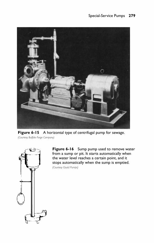
P1: FCH
GB098-06 GB098-Miller September 13, 2004 17:58 Char Count= 0
Special-Service Pumps 279
Figure 6-15 A horizontal type of centrifugal pump for sewage.(Courtesy Buffalo Forge Company)
Figure 6-16 Sump pump used to remove waterfrom a sump or pit. It starts automatically whenthe water level reaches a certain point, and itstops automatically when the sump is emptied.(Courtesy Gould Pumps)
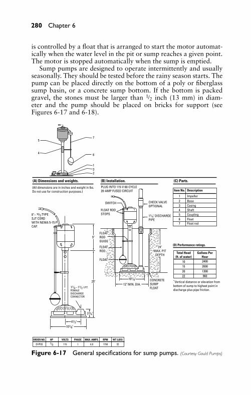
P1: FCH
GB098-06 GB098-Miller September 13, 2004 17:58 Char Count= 0
280 Chapter 6
is controlled by a float that is arranged to start the motor automat-ically when the water level in the pit or sump reaches a given point.The motor is stopped automatically when the sump is emptied.
Sump pumps are designed to operate intermittently and usuallyseasonally. They should be tested before the rainy season starts. Thepump can be placed directly on the bottom of a poly or fiberglasssump basin, or a concrete sump bottom. If the bottom is packedgravel, the stones must be larger than 1/2 inch (13 mm) in diam-eter and the pump should be placed on bricks for support (seeFigures 6-17 and 6-18).
Total Head(ft. of water)
Gallons PerHour
(D) Performance ratings.
10152022
240020001300960
Vertical distance or elevation frombottom of sump to highest point indischarge plus pipe friction.
CONCRETESUMPFLOAT
12" MIN. DIA.
FLOAT
FLOATROD
FLOATRODGUIDE
101/8"
11/4" DISCHARGEPIPE
24"MAX. PIT
DEPTH
Item No. Description
1234567
ImpellerBaseCasingShaftCouplingFloatFloat rod
CHECK VALVEOPTIONAL
(B) Installation.
SWITCH
FLOAT RODSTOPS
(All dimensions are in inches and weight in lbs. Do not use for construction purposes.)
(A) Dimensions and weights.
8"– 16/3 TYPESJT CORDWITH NEMA 5-15 PCAP.
25"
11/4 – 11/2 I.P.T.FEMALEDISCHARGECONNECTOR
2 3/4"
41/2"101/8"
ORDER NO. HP VOLTS PHASE MAX. AMPS. RPM WT (LBS)
DVP03 1/3 115 1 6.0 1750 32
9"
(C) Parts.PLUG INTO 115-V 60-CYCLE20-AMP FUSED CIRCUIT
1
6
75
4
32
Figure 6-17 General specifications for sump pumps. (Courtesy Gould Pumps)
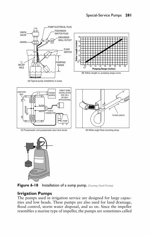
P1: FCH
GB098-06 GB098-Miller September 13, 2004 17:58 Char Count= 0
Special-Service Pumps 281
Teth
er L
engt
h (in
ches
)
Pumping Range (inches)
3.5
5.56 10 14 18 22 26 30 34 38
610
1418
2226
GREE
NW
HITE
WHITE
BLAC
K
GREE
NW
HITE
BLAC
K
BLACK
GROU
ND
POWERSOURCE
PUMP
CABLECONNECTOR
DIRECT WIREINSTALLATION
FOR 120-VOR 230-V
APPLICATIONS.
UNION
CHECKVALVE
PUMP ELECTRICAL PLUG
PIGGYBACKSWITCH PLUG
GROUNDEDWALL OUTLET
FLOATSWITCH
PUMPINGRANGE
1/8"RELIEFHOLE
JUNCTIONBOX
TETHER LENGTH
(A) Typical pump installation in sump.
(B) Tether length vs. pumping range curve.
(C) Pumpmaster and pumpmaster plus hard wired. (D) Wide angle float mounting strap.
Figure 6-18 Installation of a sump pump. (Courtesy Gould Pumps)
Irrigation PumpsThe pumps used in irrigation service are designed for large capac-ities and low heads. These pumps are also used for land drainage,flood control, storm water disposal, and so on. Since the impellerresembles a marine type of impeller, the pumps are sometimes called
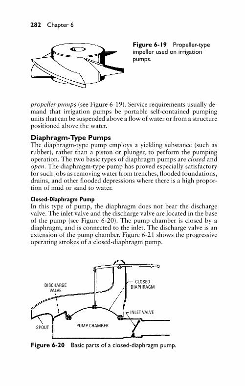
P1: FCH
GB098-06 GB098-Miller September 13, 2004 17:58 Char Count= 0
282 Chapter 6
Figure 6-19 Propeller-typeimpeller used on irrigationpumps.
propeller pumps (see Figure 6-19). Service requirements usually de-mand that irrigation pumps be portable self-contained pumpingunits that can be suspended above a flow of water or from a structurepositioned above the water.
Diaphragm-Type PumpsThe diaphragm-type pump employs a yielding substance (such asrubber), rather than a piston or plunger, to perform the pumpingoperation. The two basic types of diaphragm pumps are closed andopen. The diaphragm-type pump has proved especially satisfactoryfor such jobs as removing water from trenches, flooded foundations,drains, and other flooded depressions where there is a high propor-tion of mud or sand to water.
Closed-Diaphragm PumpIn this type of pump, the diaphragm does not bear the dischargevalve. The inlet valve and the discharge valve are located in the baseof the pump (see Figure 6-20). The pump chamber is closed by adiaphragm, and is connected to the inlet. The discharge valve is anextension of the pump chamber. Figure 6-21 shows the progressiveoperating strokes of a closed-diaphragm pump.
DISCHARGE VALVE
SPOUT PUMP CHAMBER
INLET VALVE
CLOSEDDIAPHRAGM
Figure 6-20 Basic parts of a closed-diaphragm pump.
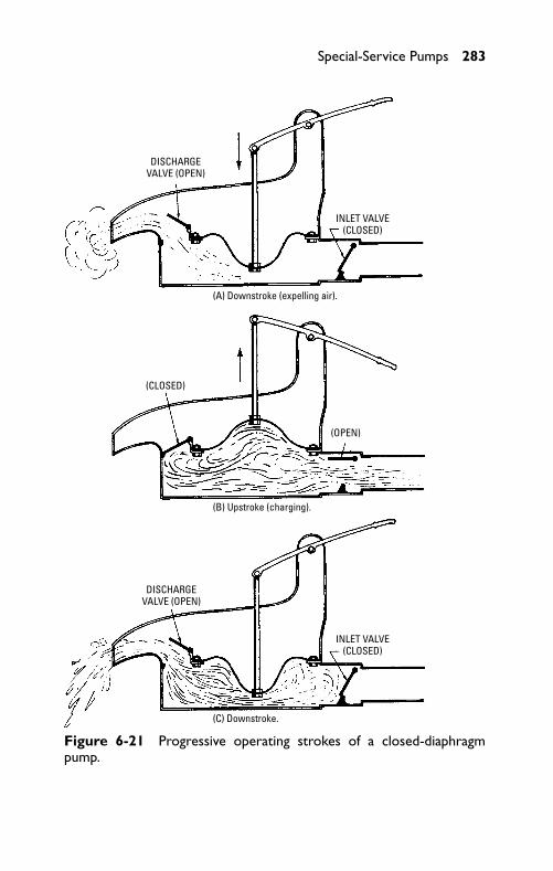
P1: FCH
GB098-06 GB098-Miller September 13, 2004 17:58 Char Count= 0
Special-Service Pumps 283
(A) Downstroke (expelling air).
DISCHARGE VALVE (OPEN)
DISCHARGE VALVE (OPEN)
(B) Upstroke (charging).
(CLOSED)
(C) Downstroke.
INLET VALVE (CLOSED)
INLET VALVE (CLOSED)
(OPEN)
Figure 6-21 Progressive operating strokes of a closed-diaphragmpump.
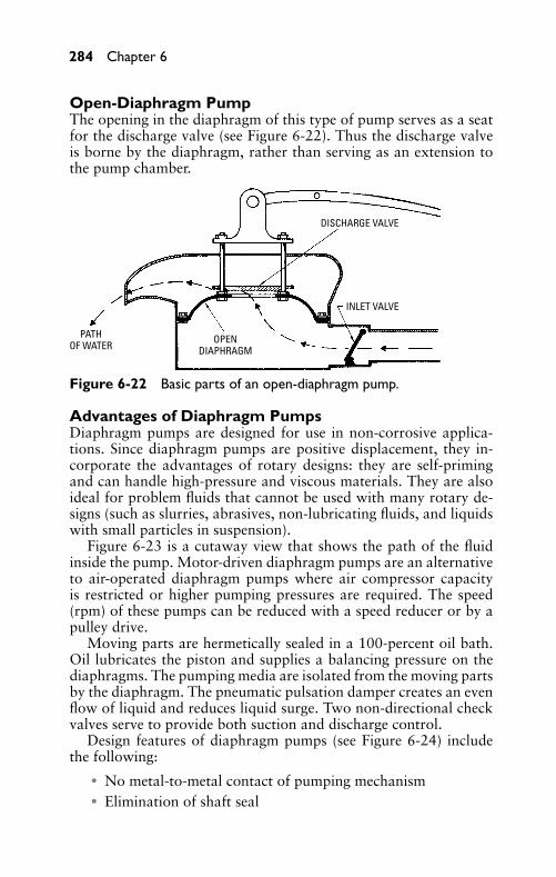
P1: FCH
GB098-06 GB098-Miller September 13, 2004 17:58 Char Count= 0
284 Chapter 6
Open-Diaphragm PumpThe opening in the diaphragm of this type of pump serves as a seatfor the discharge valve (see Figure 6-22). Thus the discharge valveis borne by the diaphragm, rather than serving as an extension tothe pump chamber.
DISCHARGE VALVE
INLET VALVE
OPENDIAPHRAGM
PATH OF WATER
Figure 6-22 Basic parts of an open-diaphragm pump.
Advantages of Diaphragm PumpsDiaphragm pumps are designed for use in non-corrosive applica-tions. Since diaphragm pumps are positive displacement, they in-corporate the advantages of rotary designs: they are self-primingand can handle high-pressure and viscous materials. They are alsoideal for problem fluids that cannot be used with many rotary de-signs (such as slurries, abrasives, non-lubricating fluids, and liquidswith small particles in suspension).
Figure 6-23 is a cutaway view that shows the path of the fluidinside the pump. Motor-driven diaphragm pumps are an alternativeto air-operated diaphragm pumps where air compressor capacityis restricted or higher pumping pressures are required. The speed(rpm) of these pumps can be reduced with a speed reducer or by apulley drive.
Moving parts are hermetically sealed in a 100-percent oil bath.Oil lubricates the piston and supplies a balancing pressure on thediaphragms. The pumping media are isolated from the moving partsby the diaphragm. The pneumatic pulsation damper creates an evenflow of liquid and reduces liquid surge. Two non-directional checkvalves serve to provide both suction and discharge control.
Design features of diaphragm pumps (see Figure 6-24) includethe following:
� No metal-to-metal contact of pumping mechanism� Elimination of shaft seal

P1: FCH
GB098-06 GB098-Miller September 13, 2004 17:58 Char Count= 0
Special-Service Pumps 285
Figure 6-23 Diaphragm pump cutaway view showing flow path.(Courtesy Sherwood)
Figure 6-24 Diaphragmpump that delivers5.3 gallons per minute at275 psi. (Courtesy Sherwood)
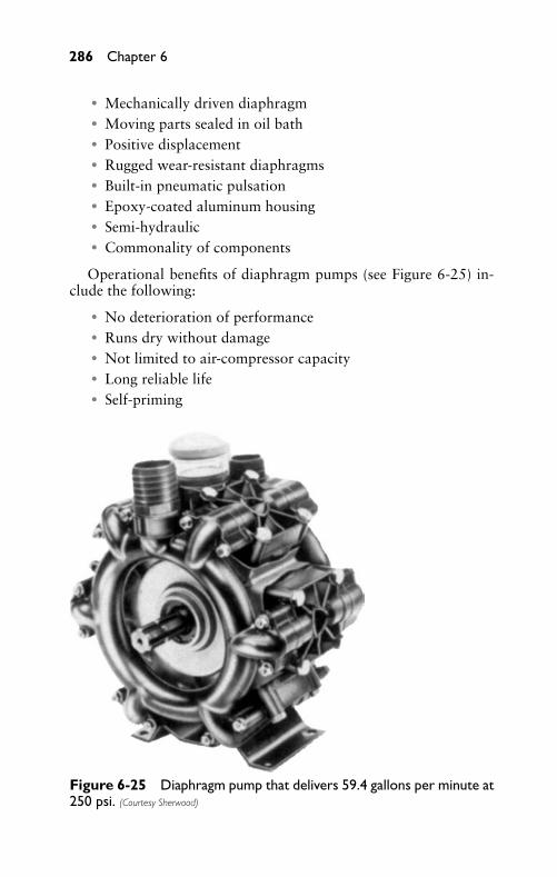
P1: FCH
GB098-06 GB098-Miller September 13, 2004 17:58 Char Count= 0
286 Chapter 6
� Mechanically driven diaphragm� Moving parts sealed in oil bath� Positive displacement� Rugged wear-resistant diaphragms� Built-in pneumatic pulsation� Epoxy-coated aluminum housing� Semi-hydraulic� Commonality of components
Operational benefits of diaphragm pumps (see Figure 6-25) in-clude the following:
� No deterioration of performance� Runs dry without damage� Not limited to air-compressor capacity� Long reliable life� Self-priming
Figure 6-25 Diaphragm pump that delivers 59.4 gallons per minute at250 psi. (Courtesy Sherwood)
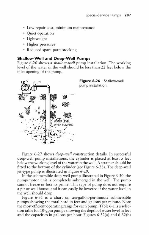
P1: FCH
GB098-06 GB098-Miller September 13, 2004 17:58 Char Count= 0
Special-Service Pumps 287
� Low repair cost, minimum maintenance� Quiet operation� Lightweight� Higher pressures� Reduced spare-parts stocking
Shallow-Well and Deep-Well PumpsFigure 6-26 shows a shallow-well pump installation. The workinglevel of the water in the well should be less than 22 feet below theinlet opening of the pump.
A
F-M
B
WATER LEVEL WHEN PUMPING
22'
OR L
ESS
Figure 6-26 Shallow-wellpump installation.
Figure 6-27 shows deep-well construction details. In successfuldeep-well pump installations, the cylinder is placed at least 5 feetbelow the working level of the water in the well. A strainer should befitted to the bottom of the cylinder (see Figure 6-28). The deep-welljet-type pump is illustrated in Figure 6-29.
In the submersible deep-well pump illustrated in Figure 6-30, thepump-motor unit is completely submerged in the well. The pumpcannot freeze or lose its prime. This type of pump does not requirea pit or well house, and it can easily be lowered if the water level inthe well should drop.
Figure 6-31 is a chart on ten-gallon-per-minute submersiblepumps showing the total head in feet and gallons per minute. Notethe most efficient operating range for each pump. Table 6-1 is a selec-tion table for 10-gpm pumps showing the depth of water level in feetand the capacities in gallons per hour. Figures 6-32(a) and 6-32(b)
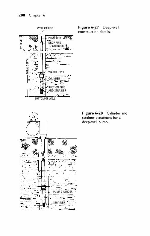
P1: FCH
GB098-06 GB098-Miller September 13, 2004 17:58 Char Count= 0
288 Chapter 6
WELL CASING
PUMP ROD
DROP PIPE TO CYLINDER
WATER LEVEL
CYLINDER
BOTTOM OF WELL
TOTA
L DE
PTH
22' L
EVEL
SUCTION PIPE AND STRAINER
Figure 6-27 Deep-wellconstruction details.
PUMP CYLINDER
STRAINER
Figure 6-28 Cylinder andstrainer placement for adeep-well pump.
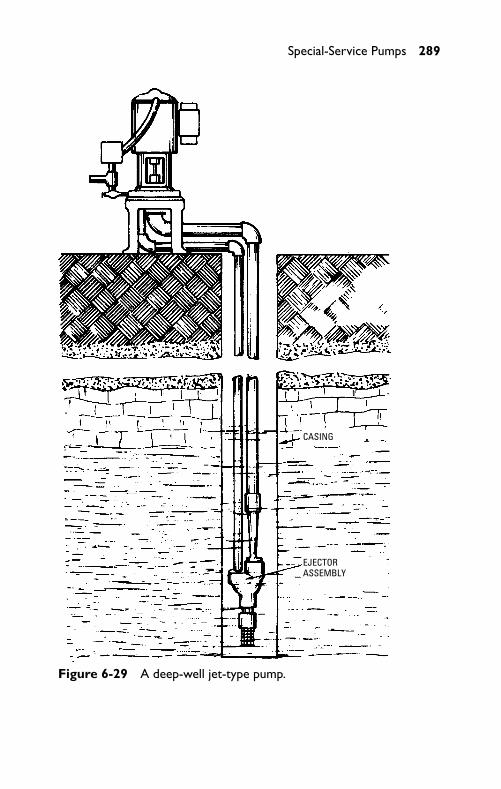
P1: FCH
GB098-06 GB098-Miller September 13, 2004 17:58 Char Count= 0
Special-Service Pumps 289
CASING
EJECTOR ASSEMBLY
Figure 6-29 A deep-well jet-type pump.
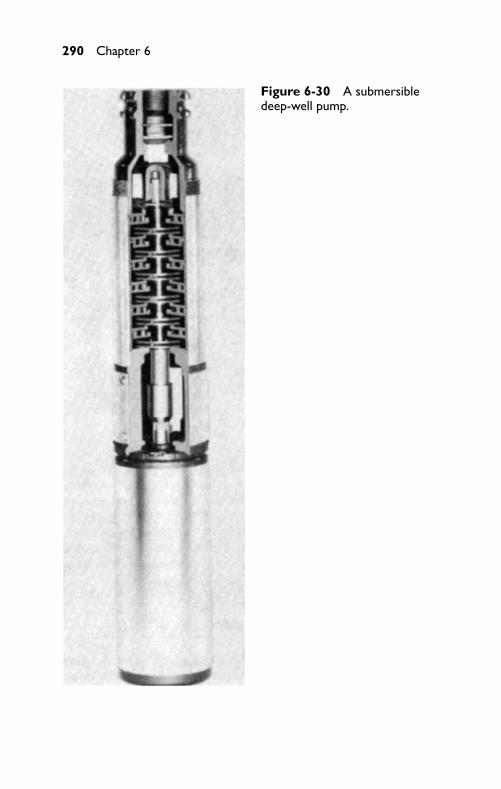
P1: FCH
GB098-06 GB098-Miller September 13, 2004 17:58 Char Count= 0
290 Chapter 6
Figure 6-30 A submersibledeep-well pump.
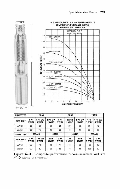
P1: FCH
GB098-06 GB098-Miller September 13, 2004 17:58 Char Count= 0
Special-Service Pumps 291
MOST EFFICIENT OPERATING RANGE
3 HP—34 STAGE
2 HP—26 STAGE
1 HP—15 STAGE
1100
1000
900
800
700
600
500
400
300
200
100
0 2 4 6 8 10 12 14 16
TOTA
L H
EAD
IN F
EET
GALLONS PER MINUTE
PUMP TYPE
PUMP TYPE
MTR. TYPE
MTR. TYPE
LENGTH
WEIGHT
LENGTH
WEIGHT
1 PH 3 WIRE
1 PH 3 WIRE
1 PH 3 WIRE
23 35
4326
32
40
25
29
37
44
33
33
41
29
33
42
50
3BA6 5BA8 7BA12
37
45
52
43
60 60
41 55
78 71
68
103
62
92
53
71
1 PH-C/S 2 WIRE
1 PH-C/S 2 WIRE
1 PH-C/S 2 WIRE
1 PH-C/S 2 WIRE
1 PH-S/P 2 WIRE
1 PH-S/P 2 WIRE
1 PH3 WIRE
3 PH3 WIRE
3 PH3 WIRE
3 PH3 WIRE
1 PH3 WIRE
1 PH3 WIRE
1 PH3 WIRE
10BA15 15BA20 20BA26 30BA34
37/8"
11/4" NPT
L
1/3 HP—6 STAGE
1/2 HP—8 STAGE
3/4 HP—12 STAGE
11/2 HP—20 STAGE
10 G.P.M.—1/3 THRU 3 H.P. 3450 R/MIN.—60-CYCLE COMPOSITE PERFORMANCE CURVES
MINIMUM WELL SIZE: 4" I.D.
Figure 6-31 Composite performance curves—minimum well size4′′ ID. (Courtesy Flint & Walling, Inc.)
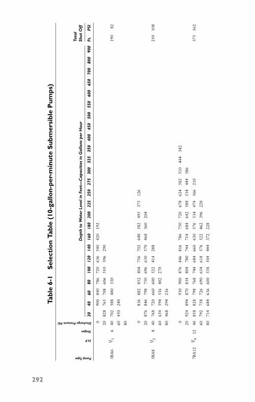
P1: FCH
GB098-06 GB098-Miller September 13, 2004 17:58 Char Count= 0
Tabl
e6-
1S
elec
tio
nTa
ble
(10-
gallo
n-pe
r-m
inut
eS
ubm
ersi
ble
Pum
ps)
Pump Type
H.P
Stages
Discharge Pressure PSITo
tal
Dep
thto
Wat
erLe
veli
nFe
et—
Cap
acit
ies
inG
allo
nsp
erH
our
Shut
Off
2040
6080
100
120
140
160
180
200
225
250
275
300
325
350
400
450
500
550
600
650
700
800
900
Ft.
PSI
090
084
078
672
063
654
042
019
2
2082
876
570
860
651
039
629
0
3BA
61 / 3
640
702
588
480
330
190
82
6045
024
0
80 083
688
285
280
475
670
264
858
249
537
512
6
2087
684
679
875
069
663
057
046
836
020
4
5BA
81 / 2
840
768
720
660
600
522
414
288
250
108
6065
459
451
640
227
0
8046
829
421
6
093
090
087
684
681
678
675
072
067
862
458
251
044
434
2
2092
489
487
083
480
478
074
471
468
464
258
853
444
438
6
7BA
123 / 4
1240
858
828
798
768
744
684
660
630
576
534
474
366
210
375
162
6079
275
872
669
065
461
857
652
246
239
622
8
8071
468
463
660
055
850
444
437
222
8
292
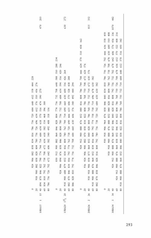
P1: FCH
GB098-06 GB098-Miller September 13, 2004 17:58 Char Count= 0
092
490
688
285
883
481
678
675
672
068
464
861
255
844
422
8
2091
890
088
285
882
880
478
075
672
669
665
461
257
651
045
627
6
10B
A15
115
4089
487
084
682
279
877
474
471
468
465
461
857
051
647
439
027
047
020
3
6083
481
079
276
273
870
867
265
461
858
253
446
839
630
0
8078
675
672
670
267
264
260
658
254
049
240
831
815
6
083
091
290
088
286
484
682
880
477
475
673
270
864
858
851
028
823
4
2092
490
689
487
685
884
682
880
478
075
673
270
868
465
459
451
642
024
6
15B
A20
11 / 220
4091
890
068
887
985
283
481
680
478
076
274
471
469
066
063
060
051
642
626
463
027
2
6088
287
084
683
481
679
277
476
273
872
069
066
663
560
657
052
843
828
8
8084
682
881
079
277
475
673
270
868
466
063
060
657
654
049
244
429
4
092
491
290
088
887
685
284
081
680
478
674
470
866
662
457
051
043
816
2
2093
692
490
690
088
287
085
883
482
280
478
676
875
070
867
262
457
6
20B
A26
226
4093
091
890
685
487
586
485
284
082
880
478
676
875
673
271
467
263
057
681
535
2
6091
890
088
887
686
485
283
481
680
479
277
475
873
871
469
667
863
058
2
8088
287
085
884
682
881
680
479
278
075
673
872
070
268
465
063
058
2
093
091
890
696
487
685
884
684
083
481
078
675
672
670
266
663
655
845
0
2093
091
890
088
887
688
885
284
082
881
680
478
076
273
870
867
863
060
051
040
8
30B
A34
334
4092
491
290
088
887
686
485
284
684
082
881
680
479
275
673
270
267
864
260
657
645
633
610
7048
2
6092
491
290
088
887
686
485
885
284
683
482
280
478
676
875
072
670
867
863
661
257
052
240
821
6
8091
890
088
887
686
485
284
684
083
482
281
680
478
676
875
073
271
468
464
861
257
051
645
034
2
293
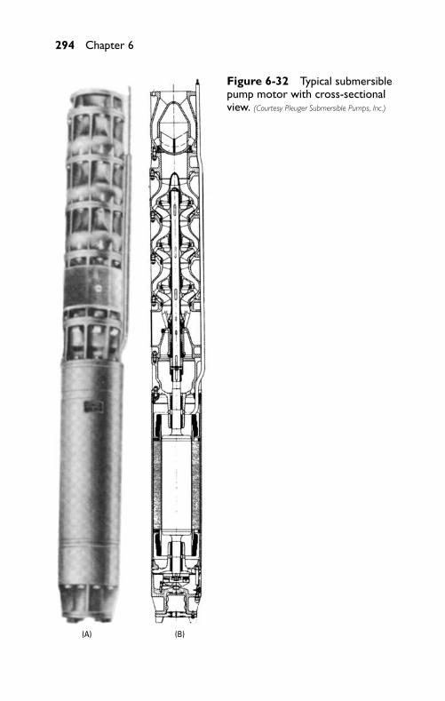
P1: FCH
GB098-06 GB098-Miller September 13, 2004 17:58 Char Count= 0
294 Chapter 6
(A) (B)
Figure 6-32 Typical submersiblepump motor with cross-sectionalview. (Courtesy Pleuger Submersible Pumps, Inc.)
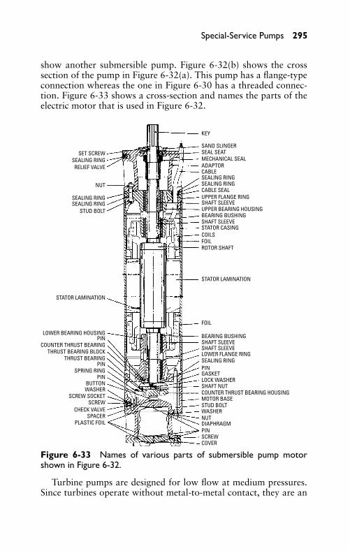
P1: FCH
GB098-06 GB098-Miller September 13, 2004 17:58 Char Count= 0
Special-Service Pumps 295
show another submersible pump. Figure 6-32(b) shows the crosssection of the pump in Figure 6-32(a). This pump has a flange-typeconnection whereas the one in Figure 6-30 has a threaded connec-tion. Figure 6-33 shows a cross-section and names the parts of theelectric motor that is used in Figure 6-32.
SET SCREWSEALING RING
SEALING RINGSEALING RING
RELIEF VALVE
NUT
STUD BOLT
STATOR LAMINATION
LOWER BEARING HOUSINGPIN
COUNTER THRUST BEARINGTHRUST BEARING BLOCK
THRUST BEARINGPIN
PIN
PIN
PIN
SPRING RING
BUTTONWASHER
SCREW SOCKETSCREW
SCREW
CHECK VALVESPACER
PLASTIC FOIL
COVER
DIAPHRAGMNUTWASHER
LOCK WASHER
STUD BOLTMOTOR BASECOUNTER THRUST BEARING HOUSINGSHAFT NUT
GASKET
SEALING RINGLOWER FLANGE RINGSHAFT SLEEVESHAFT SLEEVEBEARING BUSHING
BEARING BUSHING
FOIL
FOIL
STATOR LAMINATION
STATOR CASINGCOILS
ROTOR SHAFT
SHAFT SLEEVE
SHAFT SLEEVEUPPER BEARING HOUSING
UPPER FLANGE RINGCABLE SEALSEALING RINGSEALING RINGCABLEADAPTORMECHANICAL SEALSEAL SEATSAND SLINGER
KEY
Figure 6-33 Names of various parts of submersible pump motorshown in Figure 6-32.
Turbine pumps are designed for low flow at medium pressures.Since turbines operate without metal-to-metal contact, they are an
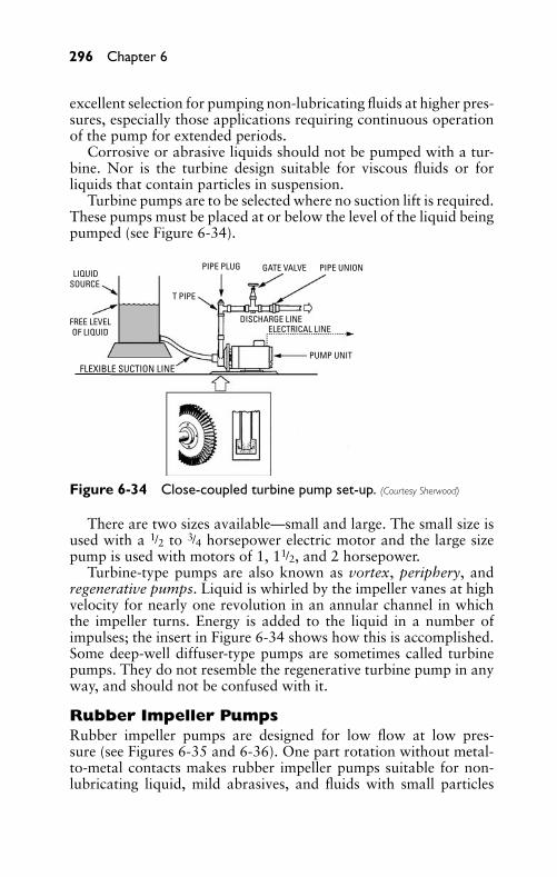
P1: FCH
GB098-06 GB098-Miller September 13, 2004 17:58 Char Count= 0
296 Chapter 6
excellent selection for pumping non-lubricating fluids at higher pres-sures, especially those applications requiring continuous operationof the pump for extended periods.
Corrosive or abrasive liquids should not be pumped with a tur-bine. Nor is the turbine design suitable for viscous fluids or forliquids that contain particles in suspension.
Turbine pumps are to be selected where no suction lift is required.These pumps must be placed at or below the level of the liquid beingpumped (see Figure 6-34).
LIQUIDSOURCE
FREE LEVEL OF LIQUID
T PIPE
PIPE PLUG GATE VALVE PIPE UNION
DISCHARGE LINEELECTRICAL LINE
PUMP UNITFLEXIBLE SUCTION LINE
Figure 6-34 Close-coupled turbine pump set-up. (Courtesy Sherwood)
There are two sizes available—small and large. The small size isused with a 1/2 to 3/4 horsepower electric motor and the large sizepump is used with motors of 1, 11/2, and 2 horsepower.
Turbine-type pumps are also known as vortex, periphery, andregenerative pumps. Liquid is whirled by the impeller vanes at highvelocity for nearly one revolution in an annular channel in whichthe impeller turns. Energy is added to the liquid in a number ofimpulses; the insert in Figure 6-34 shows how this is accomplished.Some deep-well diffuser-type pumps are sometimes called turbinepumps. They do not resemble the regenerative turbine pump in anyway, and should not be confused with it.
Rubber Impeller PumpsRubber impeller pumps are designed for low flow at low pres-sure (see Figures 6-35 and 6-36). One part rotation without metal-to-metal contacts makes rubber impeller pumps suitable for non-lubricating liquid, mild abrasives, and fluids with small particles
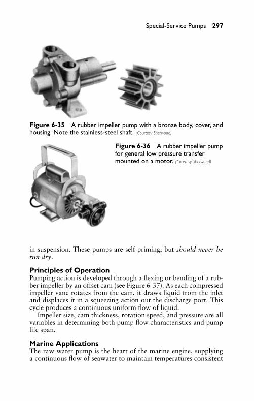
P1: FCH
GB098-06 GB098-Miller September 13, 2004 17:58 Char Count= 0
Special-Service Pumps 297
Figure 6-35 A rubber impeller pump with a bronze body, cover, andhousing. Note the stainless-steel shaft. (Courtesy Sherwood)
Figure 6-36 A rubber impeller pumpfor general low pressure transfermounted on a motor. (Courtesy Sherwood)
in suspension. These pumps are self-priming, but should never berun dry.
Principles of OperationPumping action is developed through a flexing or bending of a rub-ber impeller by an offset cam (see Figure 6-37). As each compressedimpeller vane rotates from the cam, it draws liquid from the inletand displaces it in a squeezing action out the discharge port. Thiscycle produces a continuous uniform flow of liquid.
Impeller size, cam thickness, rotation speed, and pressure are allvariables in determining both pump flow characteristics and pumplife span.
Marine ApplicationsThe raw water pump is the heart of the marine engine, supplyinga continuous flow of seawater to maintain temperatures consistent
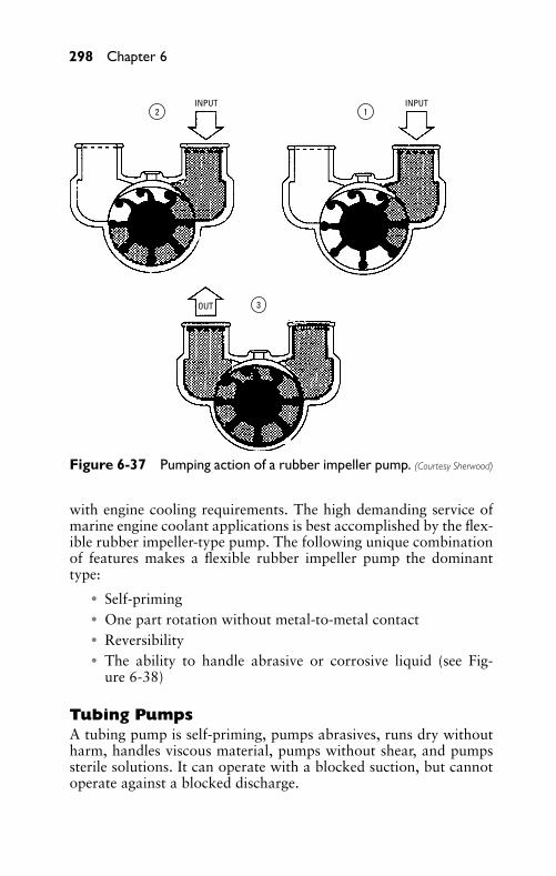
P1: FCH
GB098-06 GB098-Miller September 13, 2004 17:58 Char Count= 0
298 Chapter 6
2 1
3
INPUT INPUT
OUT
Figure 6-37 Pumping action of a rubber impeller pump. (Courtesy Sherwood)
with engine cooling requirements. The high demanding service ofmarine engine coolant applications is best accomplished by the flex-ible rubber impeller-type pump. The following unique combinationof features makes a flexible rubber impeller pump the dominanttype:
� Self-priming� One part rotation without metal-to-metal contact� Reversibility� The ability to handle abrasive or corrosive liquid (see Fig-
ure 6-38)
Tubing PumpsA tubing pump is self-priming, pumps abrasives, runs dry withoutharm, handles viscous material, pumps without shear, and pumpssterile solutions. It can operate with a blocked suction, but cannotoperate against a blocked discharge.
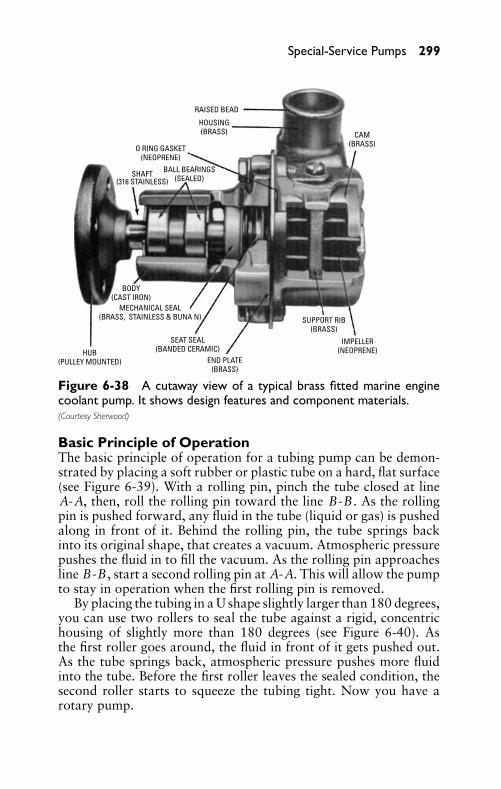
P1: FCH
GB098-06 GB098-Miller September 13, 2004 17:58 Char Count= 0
Special-Service Pumps 299
RAISED BEAD
HOUSING (BRASS)
O RING GASKET (NEOPRENE)
BALL BEARINGS (SEALED)SHAFT
(316 STAINLESS)
CAM(BRASS)
SUPPORT RIB (BRASS)
IMPELLER (NEOPRENE)
END PLATE (BRASS)
SEAT SEAL (BANDED CERAMIC)
MECHANICAL SEAL (BRASS, STAINLESS & BUNA N)
BODY(CAST IRON)
HUB(PULLEY MOUNTED)
Figure 6-38 A cutaway view of a typical brass fitted marine enginecoolant pump. It shows design features and component materials.(Courtesy Sherwood)
Basic Principle of OperationThe basic principle of operation for a tubing pump can be demon-strated by placing a soft rubber or plastic tube on a hard, flat surface(see Figure 6-39). With a rolling pin, pinch the tube closed at lineA-A, then, roll the rolling pin toward the line B-B. As the rollingpin is pushed forward, any fluid in the tube (liquid or gas) is pushedalong in front of it. Behind the rolling pin, the tube springs backinto its original shape, that creates a vacuum. Atmospheric pressurepushes the fluid in to fill the vacuum. As the rolling pin approachesline B-B, start a second rolling pin at A-A. This will allow the pumpto stay in operation when the first rolling pin is removed.
By placing the tubing in a U shape slightly larger than 180 degrees,you can use two rollers to seal the tube against a rigid, concentrichousing of slightly more than 180 degrees (see Figure 6-40). Asthe first roller goes around, the fluid in front of it gets pushed out.As the tube springs back, atmospheric pressure pushes more fluidinto the tube. Before the first roller leaves the sealed condition, thesecond roller starts to squeeze the tubing tight. Now you have arotary pump.
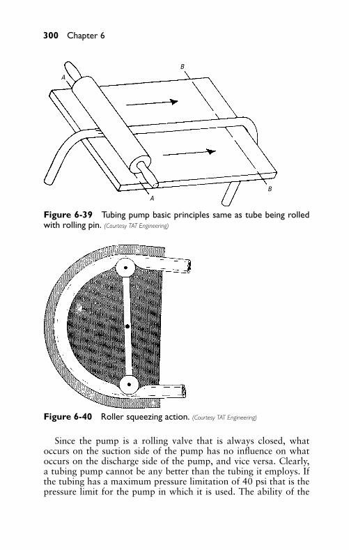
P1: FCH
GB098-06 GB098-Miller September 13, 2004 17:58 Char Count= 0
300 Chapter 6
A
B
BA
Figure 6-39 Tubing pump basic principles same as tube being rolledwith rolling pin. (Courtesy TAT Engineering)
Figure 6-40 Roller squeezing action. (Courtesy TAT Engineering)
Since the pump is a rolling valve that is always closed, whatoccurs on the suction side of the pump has no influence on whatoccurs on the discharge side of the pump, and vice versa. Clearly,a tubing pump cannot be any better than the tubing it employs. Ifthe tubing has a maximum pressure limitation of 40 psi that is thepressure limit for the pump in which it is used. The ability of the
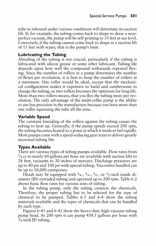
P1: FCH
GB098-06 GB098-Miller September 13, 2004 17:58 Char Count= 0
Special-Service Pumps 301
tube to rebound under various conditions will determine its suctionlift. If, for example, the tubing comes back to shape to draw a near-perfect vacuum, the pump will be self-priming to 33 feet at sea level.Conversely, if the tubing cannot come back to shape at a suction liftof 15 feet with water, that is the pump’s limit.
Lubricating the TubingAbrading of the tubing is not crucial, particularly if the tubing islubricated with silicon grease or some other lubricant. Tubing lifedepends upon how well the compound withstands repeated flex-ing. Since the number of rollers in a pump determines the numberof flexes per revolution, it is best to keep the number of rollers ata minimum. One roller would be ideal, except that the mechani-cal configuration makes it expensive to build and cumbersome tochange the tubing, so two rollers becomes the optimum for long life.More than two rollers means, that you flex the tubing more per rev-olution. The only advantage of the multi-roller pump is the abilityto use less precision in the manufacture because you have more thanone roller squeezing the tube all the time.
Variable SpeedThe constant kneading of the rollers against the tubing causes thetubing to heat up. Generally, if the pump speeds exceed 200 rpm,the tubing becomes heated to a point at which it tends to fail rapidly.Most pumps come with a speed-reducing gear train to deliver greatlyincreased tubing life.
Types AvailableThere are various types of tubing pumps available. Flow rates from1/4 cc to nearly 60 gallons per hour are available with suction lifts to28 feet, vacuums to 30 inches of mercury. Discharge pressures areup to 40 psi and 100 psi with special tubing. Viscosities handled canbe up to 10,000 centipoises.
Heads may be equipped with 1/8-, 1/4-, 3/8-, or 1/2-inch inside di-ameter (ID) extruded tubing and operated up to 200 rpm. Table 6-2shows basic flow rates for various sizes of tubing.
In the tubing pump, only the tubing contacts the chemicals.Therefore, the proper tubing has to be selected for the type ofchemical to be pumped. Tables 6-3 and 6-4 show the tubingmaterials available and the types of chemicals that can be handledby each type.
Figures 6-41 and 6-42 show the heavy-duty high-vacuum tubingpump head. At 200 rpm it can pump 438.1 gallons per hour with3/4-inch ID tubing.
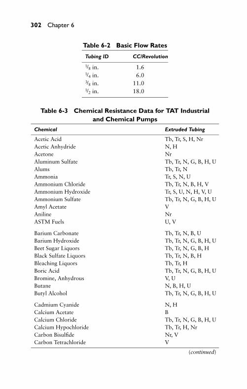
P1: FCH
GB098-06 GB098-Miller September 13, 2004 17:58 Char Count= 0
302 Chapter 6
Table 6-2 Basic Flow Rates
Tubing ID CC/Revolution
1/8 in. 1.61/4 in. 6.03/8 in. 11.01/2 in. 18.0
Table 6-3 Chemical Resistance Data for TAT Industrialand Chemical Pumps
Chemical Extruded Tubing
Acetic Acid Tb, Tr, S, H, NrAcetic Anhydride N, HAcetone NrAluminum Sulfate Tb, Tr, N, G, B, H, UAlums Tb, Tr, NAmmonia Tr, S, N, UAmmonium Chloride Tb, Tr, N, B, H, VAmmonium Hydroxide Tr, S, U, N, H, V, UAmmonium Sulfate Tb, Tr, N, G, B, H, UAmyl Acetate VAniline NrASTM Fuels U, V
Barium Carbonate Tb, Tr, N, B, UBarium Hydroxide Tb, Tr, N, G, B, H, UBeet Sugar Liquors Tb, Tr, N, G, B, HBlack Sulfate Liquors Tb, Tr, N, B, HBleaching Liquors Tb, Tr, HBoric Acid Tb, Tr, N, G, B, H, UBromine, Anhydrous V, UButane N, B, H, UButyl Alcohol Tb, Tr, N, G, B, H, U
Cadmium Cyanide N, HCalcium Acetate BCalcium Chloride Tb, Tr, N, G, B, H, UCalcium Hypochloride Tb, Tr, H, NrCarbon Bisulfide Nr, VCarbon Tetrachloride V
(continued)
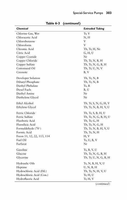
P1: FCH
GB098-06 GB098-Miller September 13, 2004 17:58 Char Count= 0
Special-Service Pumps 303
Table 6-3 (continued)
Chemical Extruded Tubing
Chlorine Gas, Wet Tr, VChloracetic Acid N, HChlorobenzene VChloroform VChromic Acid Tb, Tr, H, NrCitric Acid G, H, UCopper Cyanide NrCopper Chloride Tb, Tr, N, B, HCopper Sulfate Tb, Tr, N, G, B, HCottonseed Oil Tb, Tr, U, N, VCreosote B, V
Developer Solution Tb, Tr, N, BDibutyl Phosphate Tb, Tr, N, BDiethyl Phthalate Ts, BDiesel Fuels B, UDiethyl Amine NrDiethylene Glycol Nr
Ethyl Alcohol Tb, Tr, S, N, G, H, VEthylene Glycol Tb, Tr, N, B, H, V, U
Ferric Chloride Tb, Tr, S, B, H, UFerric Sulfate Tb, Tr, N, G, B, H, UFluoboric Acid Tb, Tr, G, HFluosilicic Acid Tb, Tr, N, G, HFormaldehyde (70◦) Tb, Tr, N, B, H, V, UFormic Acid Tb, Tr, N, HFreon 11, 12, 22, 113, 114 H, VFuel Oil Ts, U, B, VFurfarat Nr
Gasoline Ts, B, V, UGlucose Tb, Tr, N, G, B, HGlycerine Tb, Tr, U, N, G, B, H
Hydraulic Oils Ts, N, B, H, V, UHeptane U, N, B, HHydrochloric Acid (Dil.) Tb, Tr, N, H, V, UHydrochloric Acid (Con.) Tr, H, UHydrofluoric Acid Tr, H, V
(continued )
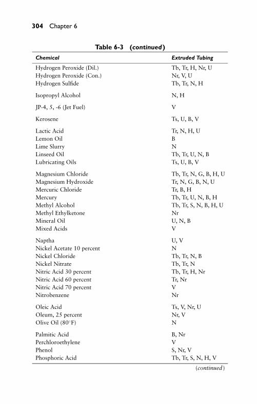
P1: FCH
GB098-06 GB098-Miller September 13, 2004 17:58 Char Count= 0
304 Chapter 6
Table 6-3 (continued)
Chemical Extruded Tubing
Hydrogen Peroxide (Dil.) Tb, Tr, H, Nr, UHydrogen Peroxide (Con.) Nr, V, UHydrogen Sulfide Tb, Tr, N, H
Isopropyl Alcohol N, H
JP-4, 5, -6 (Jet Fuel) V
Kerosene Ts, U, B, V
Lactic Acid Tr, N, H, ULemon Oil BLime Slurry NLinseed Oil Tb, Tr, U, N, BLubricating Oils Ts, U, B, V
Magnesium Chloride Tb, Tr, N, G, B, H, UMagnesium Hydroxide Tr, N, G, B, N, UMercuric Chloride Tr, B, HMercury Tb, Tr, U, N, B, HMethyl Alcohol Tb, Tr, S, N, B, H, UMethyl Ethylketone NrMineral Oil U, N, BMixed Acids V
Naptha U, VNickel Acetate 10 percent NNickel Chloride Tb, Tr, N, BNickel Nitrate Tb, Tr, NNitric Acid 30 percent Tb, Tr, H, NrNitric Acid 60 percent Tr, NrNitric Acid 70 percent VNitrobenzene Nr
Oleic Acid Ts, V, Nr, UOleum, 25 percent Nr, VOlive Oil (80◦F) N
Palmitic Acid B, NrPerchloroethylene VPhenol S, Nr, VPhosphoric Acid Tb, Tr, S, N, H, V
(continued )
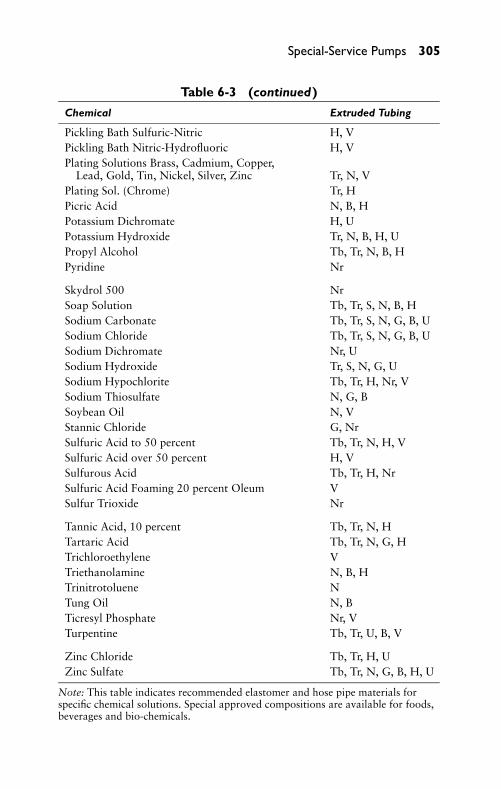
P1: FCH
GB098-06 GB098-Miller September 13, 2004 17:58 Char Count= 0
Special-Service Pumps 305
Table 6-3 (continued)
Chemical Extruded Tubing
Pickling Bath Sulfuric-Nitric H, VPickling Bath Nitric-Hydrofluoric H, VPlating Solutions Brass, Cadmium, Copper,
Lead, Gold, Tin, Nickel, Silver, Zinc Tr, N, VPlating Sol. (Chrome) Tr, HPicric Acid N, B, HPotassium Dichromate H, UPotassium Hydroxide Tr, N, B, H, UPropyl Alcohol Tb, Tr, N, B, HPyridine Nr
Skydrol 500 NrSoap Solution Tb, Tr, S, N, B, HSodium Carbonate Tb, Tr, S, N, G, B, USodium Chloride Tb, Tr, S, N, G, B, USodium Dichromate Nr, USodium Hydroxide Tr, S, N, G, USodium Hypochlorite Tb, Tr, H, Nr, VSodium Thiosulfate N, G, BSoybean Oil N, VStannic Chloride G, NrSulfuric Acid to 50 percent Tb, Tr, N, H, VSulfuric Acid over 50 percent H, VSulfurous Acid Tb, Tr, H, NrSulfuric Acid Foaming 20 percent Oleum VSulfur Trioxide Nr
Tannic Acid, 10 percent Tb, Tr, N, HTartaric Acid Tb, Tr, N, G, HTrichloroethylene VTriethanolamine N, B, HTrinitrotoluene NTung Oil N, BTicresyl Phosphate Nr, VTurpentine Tb, Tr, U, B, V
Zinc Chloride Tb, Tr, H, UZinc Sulfate Tb, Tr, N, G, B, H, U
Note: This table indicates recommended elastomer and hose pipe materials forspecific chemical solutions. Special approved compositions are available for foods,beverages and bio-chemicals.
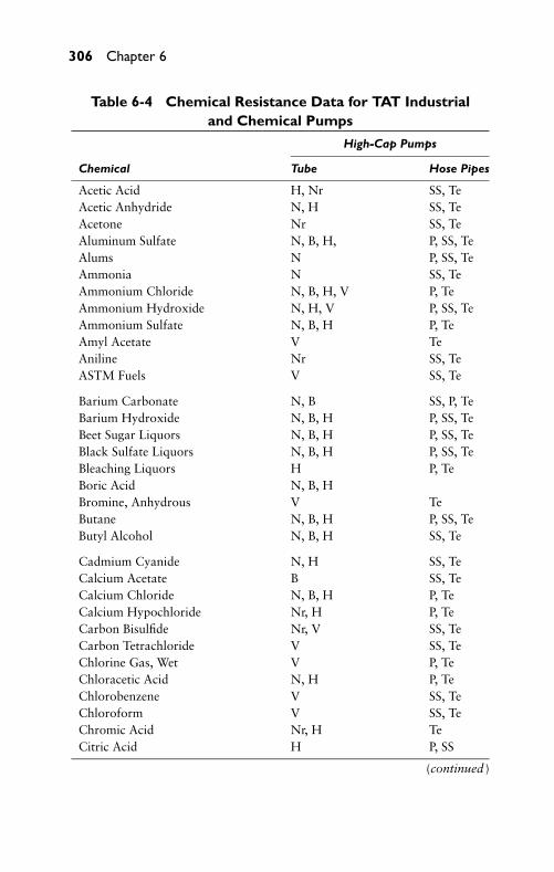
P1: FCH
GB098-06 GB098-Miller September 13, 2004 17:58 Char Count= 0
306 Chapter 6
Table 6-4 Chemical Resistance Data for TAT Industrialand Chemical Pumps
High-Cap Pumps
Chemical Tube Hose Pipes
Acetic Acid H, Nr SS, TeAcetic Anhydride N, H SS, TeAcetone Nr SS, TeAluminum Sulfate N, B, H, P, SS, TeAlums N P, SS, TeAmmonia N SS, TeAmmonium Chloride N, B, H, V P, TeAmmonium Hydroxide N, H, V P, SS, TeAmmonium Sulfate N, B, H P, TeAmyl Acetate V TeAniline Nr SS, TeASTM Fuels V SS, Te
Barium Carbonate N, B SS, P, TeBarium Hydroxide N, B, H P, SS, TeBeet Sugar Liquors N, B, H P, SS, TeBlack Sulfate Liquors N, B, H P, SS, TeBleaching Liquors H P, TeBoric Acid N, B, HBromine, Anhydrous V TeButane N, B, H P, SS, TeButyl Alcohol N, B, H SS, Te
Cadmium Cyanide N, H SS, TeCalcium Acetate B SS, TeCalcium Chloride N, B, H P, TeCalcium Hypochloride Nr, H P, TeCarbon Bisulfide Nr, V SS, TeCarbon Tetrachloride V SS, TeChlorine Gas, Wet V P, TeChloracetic Acid N, H P, TeChlorobenzene V SS, TeChloroform V SS, TeChromic Acid Nr, H TeCitric Acid H P, SS
(continued )
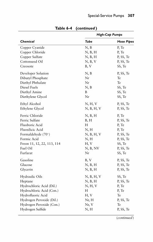
P1: FCH
GB098-06 GB098-Miller September 13, 2004 17:58 Char Count= 0
Special-Service Pumps 307
Table 6-4 (continued )
High-Cap Pumps
Chemical Tube Hose Pipes
Copper Cyanide N, B P, TeCopper Chloride N, B, H P, TeCopper Sulfate N, B, H P, SS, TeCottonseed Oil N, B, V P, SS, TeCreosote B, V SS, Te
Developer Solution N, B P, SS, TeDibutyl Phosphate Nr TeDiethyl Phthalate Nr TeDiesel Fuels N, B SS, TeDiethyl Amine B SS, TeDiethylene Glycol Nr SS, Te
Ethyl Alcohol N, H, V P, SS, TeEthylene Glycol N, B, H, V P, SS, Te
Ferric Chloride N, B, H P, TeFerric Sulfate B, H P, SS, TeFluoboric Acid H P, TeFluosilicic Acid N, H P, TeFormaldehyde (70◦) N, B, H, V P, SS, TeFormic Acid N, H P, SS, TeFreon 11, 12, 22, 113, 114 H, V SS, TeFuel Oil N, B, NV P, SS, TeFurfarat Nr SS, Te
Gasoline B, V P, SS, TeGlucose N, B, H P, SS, TeGlycerin N, B, H P, SS, Te
Hydraulic Oils N, B, H, V SS, TeHeptane N, B, H P, SS, TeHydrochloric Acid (Dil.) N, H, V P, TeHydrochloric Acid (Con.) H P, TeHydrofluoric Acid H, V TeHydrogen Peroxide (Dil.) Nr, H P, SS, TeHydrogen Peroxide (Con.) Nr, V TeHydrogen Sulfide N, H P, SS, Te
(continued )
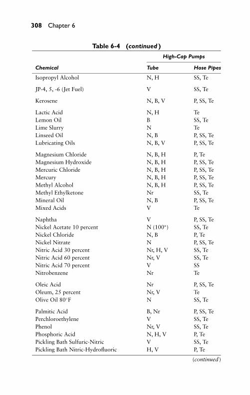
P1: FCH
GB098-06 GB098-Miller September 13, 2004 17:58 Char Count= 0
308 Chapter 6
Table 6-4 (continued )
High-Cap Pumps
Chemical Tube Hose Pipes
Isopropyl Alcohol N, H SS, Te
JP-4, 5, -6 (Jet Fuel) V SS, Te
Kerosene N, B, V P, SS, Te
Lactic Acid N, H TeLemon Oil B SS, TeLime Slurry N TeLinseed Oil N, B P, SS, TeLubricating Oils N, B, V P, SS, Te
Magnesium Chloride N, B, H P, TeMagnesium Hydroxide N, B, H P, SS, TeMercuric Chloride N, B, H P, SS, TeMercury N, B, H P, SS, TeMethyl Alcohol N, B, H P, SS, TeMethyl Ethylketone Nr SS, TeMineral Oil N, B P, SS, TeMixed Acids V Te
Naphtha V P, SS, TeNickel Acetate 10 percent N (100∗) SS, TeNickel Chloride N, B P, TeNickel Nitrate N P, SS, TeNitric Acid 30 percent Nr, H, V SS, TeNitric Acid 60 percent Nr, V SS, TeNitric Acid 70 percent V SSNitrobenzene Nr Te
Oleic Acid Nr P, SS, TeOleum, 25 percent Nr, V TeOlive Oil 80◦F N SS, Te
Palmitic Acid B, Nr P, SS, TePerchloroethylene V SS, TePhenol Nr, V SS, TePhosphoric Acid N, H, V P, TePickling Bath Sulfuric-Nitric V SS, TePickling Bath Nitric-Hydrofluoric H, V P, Te
(continued )
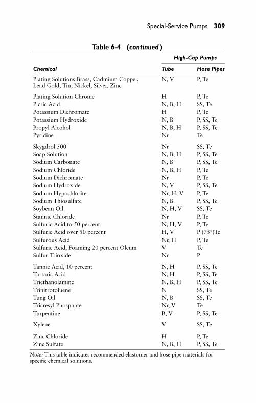
P1: FCH
GB098-06 GB098-Miller September 13, 2004 17:58 Char Count= 0
Special-Service Pumps 309
Table 6-4 (continued )
High-Cap Pumps
Chemical Tube Hose Pipes
Plating Solutions Brass, Cadmium Copper,Lead Gold, Tin, Nickel, Silver, Zinc
N, V P, Te
Plating Solution Chrome H P, TePicric Acid N, B, H SS, TePotassium Dichromate H P, TePotassium Hydroxide N, B P, SS, TePropyl Alcohol N, B, H P, SS, TePyridine Nr Te
Skygdrol 500 Nr SS, TeSoap Solution N, B, H P, SS, TeSodium Carbonate N, B P, SS, TeSodium Chloride N, B, H P, TeSodium Dichromate Nr P, TeSodium Hydroxide N, V P, SS, TeSodium Hypochlorite Nr, H, V P, TeSodium Thiosulfate N, B P, SS, TeSoybean Oil N, H, V SS, TeStannic Chloride Nr P, TeSulfuric Acid to 50 percent N, H, V P, TeSulfuric Acid over 50 percent H, V P (75◦)TeSulfurous Acid Nr, H P, TeSulfuric Acid, Foaming 20 percent Oleum V TeSulfur Trioxide Nr P
Tannic Acid, 10 percent N, H P, SS, TeTartaric Acid N, H P, SS, TeTriethanolamine N, B, H P, SS, TeTrinitrotoluene N SS, TeTung Oil N, B SS, TeTricresyl Phosphate Nr, V TeTurpentine B, V P, SS, Te
Xylene V SS, Te
Zinc Chloride H P, TeZinc Sulfate N, B, H P, SS, Te
Note: This table indicates recommended elastomer and hose pipe materials forspecific chemical solutions.
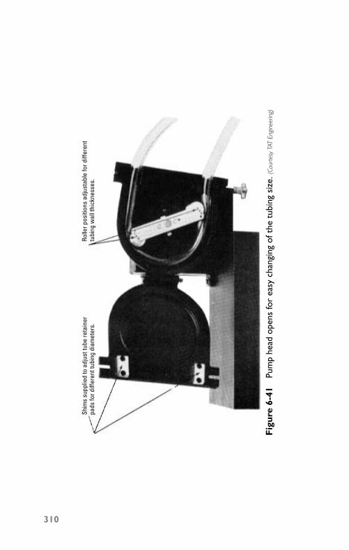
P1: FCH
GB098-06 GB098-Miller September 13, 2004 17:58 Char Count= 0
Shim
s su
pplie
d to
adj
ust t
ube
reta
iner
pads
for d
iffer
ent t
ubin
g di
amet
ers.
Rolle
r pos
ition
s ad
just
able
for d
iffer
ent
tubi
ng w
all t
hick
ness
es.
Fig
ure
6-41
Pum
phe
adop
ens
for
easy
chan
ging
ofth
etu
bing
size
. (Co
urte
syTA
TEn
gine
erin
g)
310
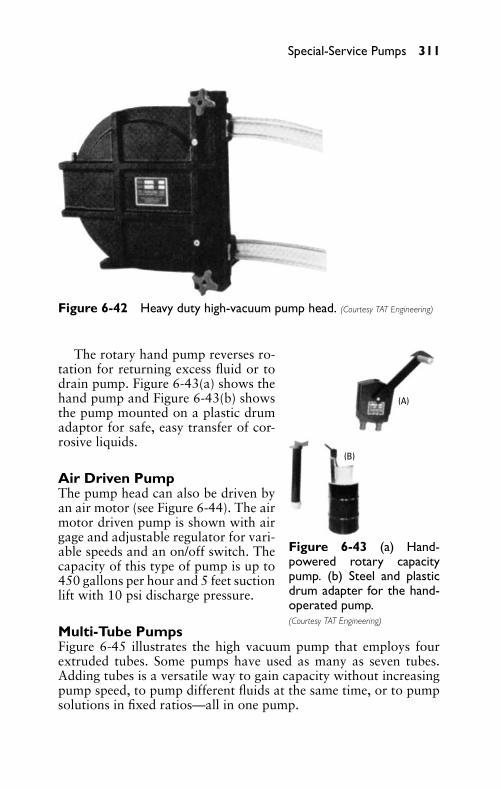
P1: FCH
GB098-06 GB098-Miller September 13, 2004 17:58 Char Count= 0
Special-Service Pumps 311
Figure 6-42 Heavy duty high-vacuum pump head. (Courtesy TAT Engineering)
(A)
(B)
Figure 6-43 (a) Hand-powered rotary capacitypump. (b) Steel and plasticdrum adapter for the hand-operated pump.(Courtesy TAT Engineering)
The rotary hand pump reverses ro-tation for returning excess fluid or todrain pump. Figure 6-43(a) shows thehand pump and Figure 6-43(b) showsthe pump mounted on a plastic drumadaptor for safe, easy transfer of cor-rosive liquids.
Air Driven PumpThe pump head can also be driven byan air motor (see Figure 6-44). The airmotor driven pump is shown with airgage and adjustable regulator for vari-able speeds and an on/off switch. Thecapacity of this type of pump is up to450 gallons per hour and 5 feet suctionlift with 10 psi discharge pressure.
Multi-Tube PumpsFigure 6-45 illustrates the high vacuum pump that employs fourextruded tubes. Some pumps have used as many as seven tubes.Adding tubes is a versatile way to gain capacity without increasingpump speed, to pump different fluids at the same time, or to pumpsolutions in fixed ratios—all in one pump.
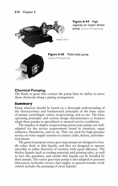
P1: FCH
GB098-06 GB098-Miller September 13, 2004 17:58 Char Count= 0
312 Chapter 6
Figure 6-44 Highcapacity air motor drivenpump. (Courtesy TAT Engineering)
Figure 6-45 Multi-tube pump.(Courtesy TAT Engineering)
Chemical PumpingThe fluids or gases that contact the pump limit its ability to movethose chemicals along a piping arrangement.
SummaryPump selection should be based on a thorough understanding ofthe characteristics and fundamental principles of the basic typesof pumps (centrifugal, rotary, reciprocating, and so on). The basicoperating principles and various design characteristics or featuresadapt these pumps to specialized or unusual service conditions.
The simplex or duplex reciprocating piston-type pumps are well-adapted for the service requirements found in tanneries, sugarrefineries, bleacheries, and so on. They are used for high-pressureservice on water supply systems in country clubs, dairies, and indus-trial plants.
The general-purpose rotary gear-type pumps are designed to han-dle either thick or thin liquids, and they are designed to operatesmoothly in either direction of rotation with equal efficiency. Thethicker liquids (such as roofing materials and printing inks), as wellas fuel oils, gasolines, and similar thin liquids can be handled bythese pumps. The rotary gear-type pump is also adapted to pressurelubrication, hydraulic service, fuel supply, or general transfer work(which includes the pumping of clean liquids).
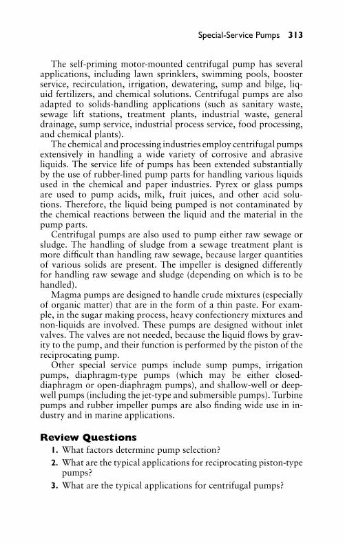
P1: FCH
GB098-06 GB098-Miller September 13, 2004 17:58 Char Count= 0
Special-Service Pumps 313
The self-priming motor-mounted centrifugal pump has severalapplications, including lawn sprinklers, swimming pools, boosterservice, recirculation, irrigation, dewatering, sump and bilge, liq-uid fertilizers, and chemical solutions. Centrifugal pumps are alsoadapted to solids-handling applications (such as sanitary waste,sewage lift stations, treatment plants, industrial waste, generaldrainage, sump service, industrial process service, food processing,and chemical plants).
The chemical and processing industries employ centrifugal pumpsextensively in handling a wide variety of corrosive and abrasiveliquids. The service life of pumps has been extended substantiallyby the use of rubber-lined pump parts for handling various liquidsused in the chemical and paper industries. Pyrex or glass pumpsare used to pump acids, milk, fruit juices, and other acid solu-tions. Therefore, the liquid being pumped is not contaminated bythe chemical reactions between the liquid and the material in thepump parts.
Centrifugal pumps are also used to pump either raw sewage orsludge. The handling of sludge from a sewage treatment plant ismore difficult than handling raw sewage, because larger quantitiesof various solids are present. The impeller is designed differentlyfor handling raw sewage and sludge (depending on which is to behandled).
Magma pumps are designed to handle crude mixtures (especiallyof organic matter) that are in the form of a thin paste. For exam-ple, in the sugar making process, heavy confectionery mixtures andnon-liquids are involved. These pumps are designed without inletvalves. The valves are not needed, because the liquid flows by grav-ity to the pump, and their function is performed by the piston of thereciprocating pump.
Other special service pumps include sump pumps, irrigationpumps, diaphragm-type pumps (which may be either closed-diaphragm or open-diaphragm pumps), and shallow-well or deep-well pumps (including the jet-type and submersible pumps). Turbinepumps and rubber impeller pumps are also finding wide use in in-dustry and in marine applications.
Review Questions1. What factors determine pump selection?2. What are the typical applications for reciprocating piston-type
pumps?3. What are the typical applications for centrifugal pumps?
P1: FCH
GB098-06 GB098-Miller September 13, 2004 17:58 Char Count= 0
314 Chapter 6
4. What types of pumps are suitable for the chemical and theprocessing industry?
5. What design feature is important in the selection of pumps forraw sewage and sludge?
6. What is the chief factor in determining whether to select ashallow-well or a deep-well pump?
7. What type of liquids can the rotary gear-type pump handle?8. What type of pump would you select for a swimming pool?9. What types of pumps are used widely in the paper industry?
10. What does the term magma mean?11. Where does the sump pump operate?12. What types of pumps are utilized in irrigation systems?13. Where are rubber impeller pumps used?14. What are some advantages of diaphragm pumps?15. Where are turbine pumps used?

P1: FCH
GB098-07 GB093-Miller September 13, 2004 18:0 Char Count= 0
Part III
Hydraulics
315

P1: FCH
GB098-07 GB093-Miller September 13, 2004 18:0 Char Count= 0
316
P1: FCH
GB098-07 GB093-Miller September 13, 2004 18:0 Char Count= 0
Chapter 7Hydraulic AccumulatorsAn accumulator is a storage device that stores liquid under pressure,so that it can serve as a reservoir and regulator of power. A simpleaccumulator is sometimes used in a household water system. It usu-ally consists of a tee with a side branch pipe that is capped. The airthat is trapped in the side branch pipe is compressed, and then actslike a compressed spring. As a faucet is opened or closed quickly, asudden change in pressure and flow occurs. The trapped air acts asa cushion (or shock absorber) to prevent water hammering in thepiping system.
In industrial hydraulics, the accumulator is an important com-ponent in many hydraulic systems. A hydraulic accumulator is de-signed to accumulate energy that is to be expended intermittently,which enables the pump, operating under uniform load, to meet anintermittent or fluctuating demand for power. However, there are anumber of other uses for accumulators in industry.
The hydraulic accumulator can be compared to the more com-mon storage battery in that energy is stored until it is needed. The hy-draulic accumulator stores hydraulic energy, and the storage battery(simply called the accumulator in England) stores electrical energy.
Basic Construction and OperationFollowing are the essential parts (see Figure 7-1) of the weight-loaded accumulator:
� Plunger or ram� Cylinder� Weights
In the accumulator, a plunger is placed within a vertical cylinderthat is closed at the lower end and provided with a stuffing box atthe upper end. Weights are secured in position at the upper end ofthe plunger to produce the desired pressure. An outlet and an inletfor the liquid are located at the lower end of the cylinder.
As shown in Figure 7-1, water is forced into the cylinder by meansof the force pump, which causes the weighted plunger to rise. Theforce or pressure from the weighted plunger on the water is transmit-ted to the machines operated by the system, as long as the plungerhas not reached the lower end of its stroke.
During periods when there is no demand for power, the plungeris prevented from rising too high and leaving the cylinder by meansof stops that arrest the motion of the plunger when it arrives at the
317
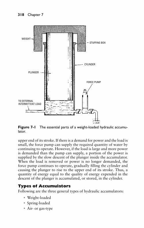
P1: FCH
GB098-07 GB093-Miller September 13, 2004 18:0 Char Count= 0
318 Chapter 7
WEIGHT
PLUNGER
TO EXTERNALINTERMITTENT LOAD
FORCE PUMP
CYLINDER
STUFFING BOX
Figure 7-1 The essential parts of a weight-loaded hydraulic accumu-lator.
upper end of its stroke. If there is a demand for power and the load issmall, the force pump can supply the required quantity of water bycontinuing to operate. However, if the load is large and more poweris demanded than the pump can supply, a portion of the power issupplied by the slow descent of the plunger inside the accumulator.When the load is removed or power is no longer demanded, theforce pump continues to operate, gradually filling the cylinder andcausing the plunger to rise to the upper end of its stroke. Thus, aquantity of energy equal to the quality of energy expended in thedescent of the plunger is accumulated, or stored, in the cylinder.
Types of AccumulatorsFollowing are the three general types of hydraulic accumulators:
� Weight-loaded� Spring-loaded� Air- or gas-type
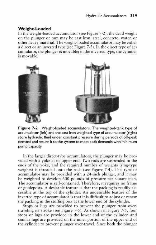
P1: FCH
GB098-07 GB093-Miller September 13, 2004 18:0 Char Count= 0
Hydraulic Accumulators 319
Weight-LoadedIn the weight-loaded accumulator (see Figure 7-2), the dead weighton the plunger or ram may be cast iron, steel, concrete, water, orother heavy material. The weight-loaded accumulator may be eithera direct or an inverted type (see Figure 7-3). In the direct type of ac-cumulator, the plunger is movable; in the inverted type, the cylinderis movable.
Figure 7-2 Weight-loaded accumulators. The weighted-tank type ofaccumulator (left) and the cast iron weighted type of accumulator (right)store hydraulic fluid under constant pressure during periods of off-peakdemand and return it to the system to meet peak demands with minimumpump capacity.
In the larger direct-type accumulators, the plunger may be pro-vided with a yoke at its upper end. Two rods are suspended in theends of the yoke, and the required number of weights (ring-typeweights) is threaded onto the rods (see Figure 7-4). This type ofaccumulator may be provided with a 24-inch plunger, and it maybe weighted to develop 600 pounds of pressure per square inch.The accumulator is self-contained. Therefore, it requires no frameor guideposts. A desirable feature is that the packing is readily ac-cessible at the top of the cylinder. An undesirable feature of theinverted type of accumulator is that it is difficult to adjust or renewthe packing in the stuffing box at the lower end of the cylinder.
Stops or lugs are provided to prevent the plunger from over-traveling its stroke (see Figure 7-5). As shown in Figure 7-5, fourstops or lugs are provided in the lower end of the cylinder, andsimilar lugs are provided on the inner portion of the upper end ofthe cylinder to prevent plunger over-travel. Since both the plunger
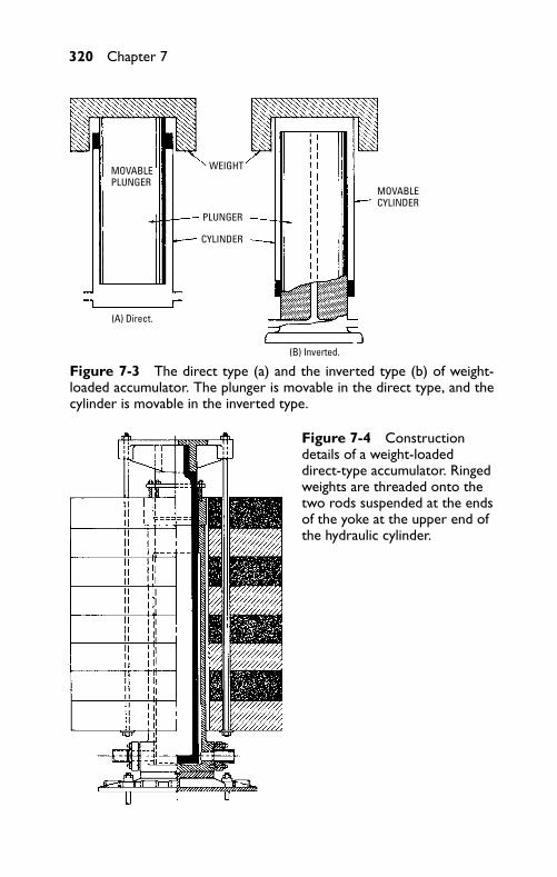
P1: FCH
GB098-07 GB093-Miller September 13, 2004 18:0 Char Count= 0
320 Chapter 7
MOVABLE PLUNGER
WEIGHT
PLUNGER
CYLINDER
(A) Direct.
(B) Inverted.
MOVABLECYLINDER
Figure 7-3 The direct type (a) and the inverted type (b) of weight-loaded accumulator. The plunger is movable in the direct type, and thecylinder is movable in the inverted type.
Figure 7-4 Constructiondetails of a weight-loadeddirect-type accumulator. Ringedweights are threaded onto thetwo rods suspended at the endsof the yoke at the upper end ofthe hydraulic cylinder.
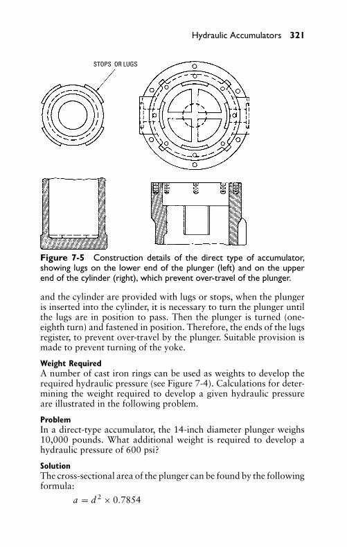
P1: FCH
GB098-07 GB093-Miller September 13, 2004 18:0 Char Count= 0
Hydraulic Accumulators 321
STOPS OR LUGS
Figure 7-5 Construction details of the direct type of accumulator,showing lugs on the lower end of the plunger (left) and on the upperend of the cylinder (right), which prevent over-travel of the plunger.
and the cylinder are provided with lugs or stops, when the plungeris inserted into the cylinder, it is necessary to turn the plunger untilthe lugs are in position to pass. Then the plunger is turned (one-eighth turn) and fastened in position. Therefore, the ends of the lugsregister, to prevent over-travel by the plunger. Suitable provision ismade to prevent turning of the yoke.
Weight RequiredA number of cast iron rings can be used as weights to develop therequired hydraulic pressure (see Figure 7-4). Calculations for deter-mining the weight required to develop a given hydraulic pressureare illustrated in the following problem.
ProblemIn a direct-type accumulator, the 14-inch diameter plunger weighs10,000 pounds. What additional weight is required to develop ahydraulic pressure of 600 psi?
SolutionThe cross-sectional area of the plunger can be found by the followingformula:
a = d 2 × 0.7854
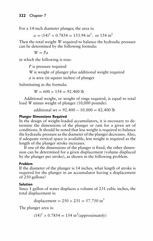
P1: FCH
GB098-07 GB093-Miller September 13, 2004 18:0 Char Count= 0
322 Chapter 7
For a 14-inch diameter plunger, the area is:
a = (14)2 × 0.7854 = 153.94 in2, or 154 in2
Then the total weight W required to balance the hydraulic pressurecan be determined by the following formula:
W = Pa
in which the following is true:
P is pressure requiredW is weight of plunger plus additional weight requireda is area (in square inches) of plunger
Substituting in the formula:
W = 600 × 154 = 92,400 lb
Additional weight, or weight of rings required, is equal to totalload W minus weight of plunger (10,000 pounds):
additional wt = 92,400 − 10,000 = 82,400 lb
Plunger Dimensions RequiredIn the design of weight-loaded accumulators, it is necessary to de-termine the dimensions of the plunger or ram for a given set ofconditions. It should be noted that less weight is required to balancethe hydraulic pressure as the diameter of the plunger decreases. Also,if adequate vertical space is available, less weight is required as thelength of the plunger stroke increases.
If one of the dimensions of the plunger is fixed, the other dimen-sion can be determined for a given displacement (volume displacedby the plunger per stroke), as shown in the following problem.
ProblemIf the diameter of the plunger is 14 inches, what length of stroke isrequired for the plunger in an accumulator having a displacementof 250 gallons?
SolutionSince 1 gallon of water displaces a volume of 231 cubic inches, thetotal displacement is:
displacement = 250 × 231 = 57,750 in3
The plunger area is:
(14)2 × 0.7854 = 154 in2(approximately)
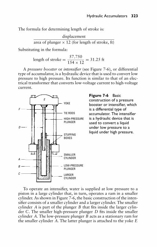
P1: FCH
GB098-07 GB093-Miller September 13, 2004 18:0 Char Count= 0
Hydraulic Accumulators 323
The formula for determining length of stroke is:
displacementarea of plunger × 12 (for length of stroke, ft)
Substituting in the formula:
length of stroke = 57,750154 × 12
= 31.25 ft
A pressure booster or intensifier (see Figure 7-6), or differentialtype of accumulator, is a hydraulic device that is used to convert lowpressure to high pressure. Its function is similar to that of an elec-trical transformer that converts low-voltage current to high-voltagecurrent.
EYOKE
TIE RODS
HIGH-PRESSURE PLUNGER
STUFFING BOXES
SMALLER CYLINDER
LOW-PRESSURE PLUNGER
LARGER CYLINDER
F
D
A
B
C
Figure 7-6 Basicconstruction of a pressurebooster or intensifier, whichis a differential type ofaccumulator. The intensifieris a hydraulic device that isused to convert a liquidunder low pressure to aliquid under high pressure.
To operate an intensifier, water is supplied at low pressure to apiston in a large cylinder that, in turn, operates a ram in a smallercylinder. As shown in Figure 7-6, the basic construction of the inten-sifier consists of a smaller cylinder and a larger cylinder. The smallercylinder A is part of the plunger B that fits inside the larger cylin-der C. The smaller high-pressure plunger D fits inside the smallercylinder A. The low-pressure plunger B acts as a stationary ram forthe smaller cylinder A. The latter plunger is attached to the yoke E
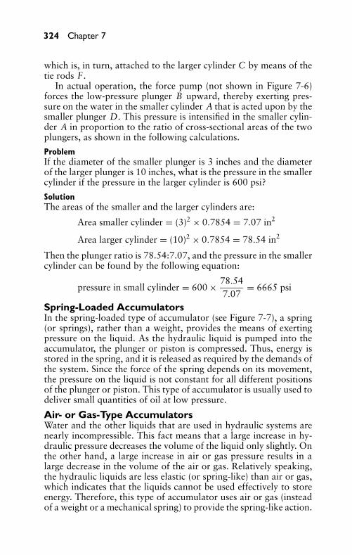
P1: FCH
GB098-07 GB093-Miller September 13, 2004 18:0 Char Count= 0
324 Chapter 7
which is, in turn, attached to the larger cylinder C by means of thetie rods F .
In actual operation, the force pump (not shown in Figure 7-6)forces the low-pressure plunger B upward, thereby exerting pres-sure on the water in the smaller cylinder A that is acted upon by thesmaller plunger D. This pressure is intensified in the smaller cylin-der A in proportion to the ratio of cross-sectional areas of the twoplungers, as shown in the following calculations.
ProblemIf the diameter of the smaller plunger is 3 inches and the diameterof the larger plunger is 10 inches, what is the pressure in the smallercylinder if the pressure in the larger cylinder is 600 psi?
SolutionThe areas of the smaller and the larger cylinders are:
Area smaller cylinder = (3)2 × 0.7854 = 7.07 in2
Area larger cylinder = (10)2 × 0.7854 = 78.54 in2
Then the plunger ratio is 78.54:7.07, and the pressure in the smallercylinder can be found by the following equation:
pressure in small cylinder = 600 × 78.547.07
= 6665 psi
Spring-Loaded AccumulatorsIn the spring-loaded type of accumulator (see Figure 7-7), a spring(or springs), rather than a weight, provides the means of exertingpressure on the liquid. As the hydraulic liquid is pumped into theaccumulator, the plunger or piston is compressed. Thus, energy isstored in the spring, and it is released as required by the demands ofthe system. Since the force of the spring depends on its movement,the pressure on the liquid is not constant for all different positionsof the plunger or piston. This type of accumulator is usually used todeliver small quantities of oil at low pressure.
Air- or Gas-Type AccumulatorsWater and the other liquids that are used in hydraulic systems arenearly incompressible. This fact means that a large increase in hy-draulic pressure decreases the volume of the liquid only slightly. Onthe other hand, a large increase in air or gas pressure results in alarge decrease in the volume of the air or gas. Relatively speaking,the hydraulic liquids are less elastic (or spring-like) than air or gas,which indicates that the liquids cannot be used effectively to storeenergy. Therefore, this type of accumulator uses air or gas (insteadof a weight or a mechanical spring) to provide the spring-like action.
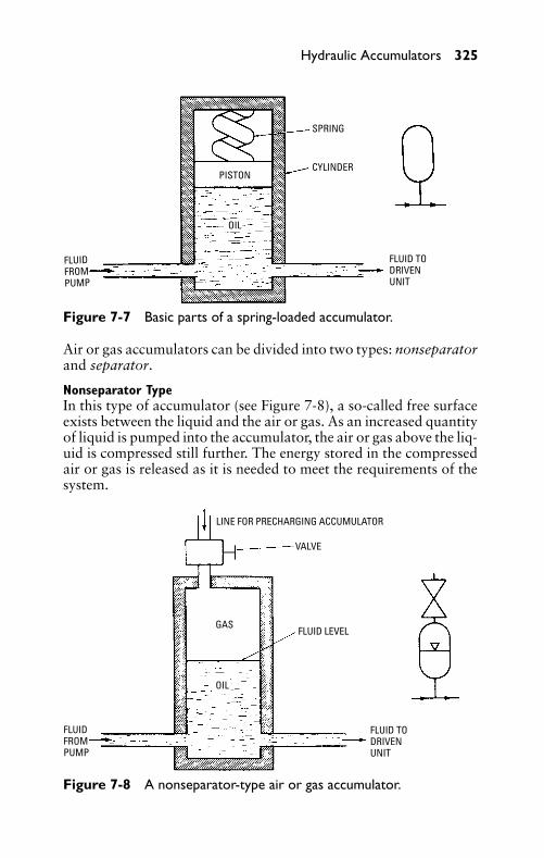
P1: FCH
GB098-07 GB093-Miller September 13, 2004 18:0 Char Count= 0
Hydraulic Accumulators 325
SPRING
CYLINDER
FLUID TODRIVENUNIT
FLUIDFROMPUMP
PISTON
OIL
Figure 7-7 Basic parts of a spring-loaded accumulator.
Air or gas accumulators can be divided into two types: nonseparatorand separator.
Nonseparator TypeIn this type of accumulator (see Figure 7-8), a so-called free surfaceexists between the liquid and the air or gas. As an increased quantityof liquid is pumped into the accumulator, the air or gas above the liq-uid is compressed still further. The energy stored in the compressedair or gas is released as it is needed to meet the requirements of thesystem.
LINE FOR PRECHARGING ACCUMULATOR
VALVE
FLUID LEVELGAS
OIL
FLUIDFROMPUMP
FLUID TODRIVENUNIT
Figure 7-8 A nonseparator-type air or gas accumulator.
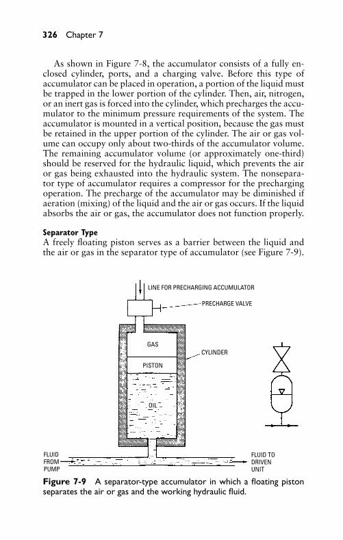
P1: FCH
GB098-07 GB093-Miller September 13, 2004 18:0 Char Count= 0
326 Chapter 7
As shown in Figure 7-8, the accumulator consists of a fully en-closed cylinder, ports, and a charging valve. Before this type ofaccumulator can be placed in operation, a portion of the liquid mustbe trapped in the lower portion of the cylinder. Then, air, nitrogen,or an inert gas is forced into the cylinder, which precharges the accu-mulator to the minimum pressure requirements of the system. Theaccumulator is mounted in a vertical position, because the gas mustbe retained in the upper portion of the cylinder. The air or gas vol-ume can occupy only about two-thirds of the accumulator volume.The remaining accumulator volume (or approximately one-third)should be reserved for the hydraulic liquid, which prevents the airor gas being exhausted into the hydraulic system. The nonsepara-tor type of accumulator requires a compressor for the prechargingoperation. The precharge of the accumulator may be diminished ifaeration (mixing) of the liquid and the air or gas occurs. If the liquidabsorbs the air or gas, the accumulator does not function properly.
Separator TypeA freely floating piston serves as a barrier between the liquid andthe air or gas in the separator type of accumulator (see Figure 7-9).
LINE FOR PRECHARGING ACCUMULATOR
PRECHARGE VALVE
GAS
OIL
FLUIDFROMPUMP
FLUID TODRIVENUNIT
PISTON
CYLINDER
Figure 7-9 A separator-type accumulator in which a floating pistonseparates the air or gas and the working hydraulic fluid.
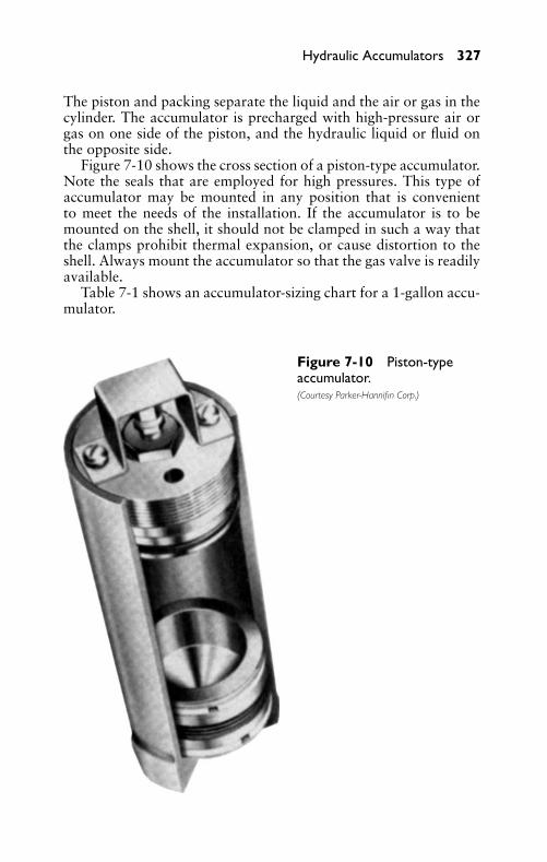
P1: FCH
GB098-07 GB093-Miller September 13, 2004 18:0 Char Count= 0
Hydraulic Accumulators 327
The piston and packing separate the liquid and the air or gas in thecylinder. The accumulator is precharged with high-pressure air orgas on one side of the piston, and the hydraulic liquid or fluid onthe opposite side.
Figure 7-10 shows the cross section of a piston-type accumulator.Note the seals that are employed for high pressures. This type ofaccumulator may be mounted in any position that is convenientto meet the needs of the installation. If the accumulator is to bemounted on the shell, it should not be clamped in such a way thatthe clamps prohibit thermal expansion, or cause distortion to theshell. Always mount the accumulator so that the gas valve is readilyavailable.
Table 7-1 shows an accumulator-sizing chart for a 1-gallon accu-mulator.
Figure 7-10 Piston-typeaccumulator.(Courtesy Parker-Hannifin Corp.)
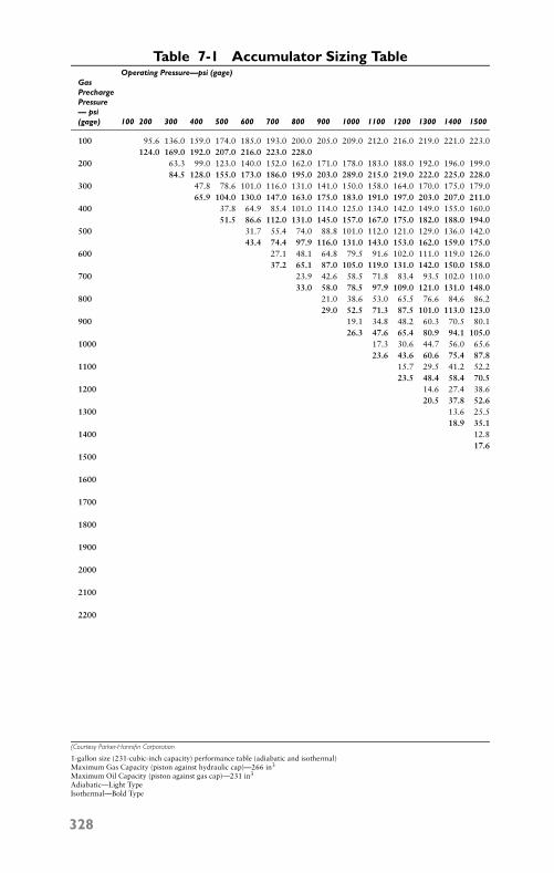
P1: FCH
GB098-07 GB093-Miller September 13, 2004 18:0 Char Count= 0
Table 7-1 Accumulator Sizing TableOperating Pressure—psi (gage)
GasPrechargePressure— psi(gage) 100 200 300 400 500 600 700 800 900 1000 1100 1200 1300 1400 1500
100 95.6 136.0 159.0 174.0 185.0 193.0 200.0 205.0 209.0 212.0 216.0 219.0 221.0 223.0124.0 169.0 192.0 207.0 216.0 223.0 228.0
200 63.3 99.0 123.0 140.0 152.0 162.0 171.0 178.0 183.0 188.0 192.0 196.0 199.084.5 128.0 155.0 173.0 186.0 195.0 203.0 289.0 215.0 219.0 222.0 225.0 228.0
300 47.8 78.6 101.0 116.0 131.0 141.0 150.0 158.0 164.0 170.0 175.0 179.065.9 104.0 130.0 147.0 163.0 175.0 183.0 191.0 197.0 203.0 207.0 211.0
400 37.8 64.9 85.4 101.0 114.0 125.0 134.0 142.0 149.0 155.0 160.051.5 86.6 112.0 131.0 145.0 157.0 167.0 175.0 182.0 188.0 194.0
500 31.7 55.4 74.0 88.8 101.0 112.0 121.0 129.0 136.0 142.043.4 74.4 97.9 116.0 131.0 143.0 153.0 162.0 159.0 175.0
600 27.1 48.1 64.8 79.5 91.6 102.0 111.0 119.0 126.037.2 65.1 87.0 105.0 119.0 131.0 142.0 150.0 158.0
700 23.9 42.6 58.5 71.8 83.4 93.5 102.0 110.033.0 58.0 78.5 97.9 109.0 121.0 131.0 148.0
800 21.0 38.6 53.0 65.5 76.6 84.6 86.229.0 52.5 71.3 87.5 101.0 113.0 123.0
900 19.1 34.8 48.2 60.3 70.5 80.126.3 47.6 65.4 80.9 94.1 105.0
1000 17.3 30.6 44.7 56.0 65.623.6 43.6 60.6 75.4 87.8
1100 15.7 29.5 41.2 52.223.5 48.4 58.4 70.5
1200 14.6 27.4 38.620.5 37.8 52.6
1300 13.6 25.518.9 35.1
1400 12.817.6
1500
1600
1700
1800
1900
2000
2100
2200
(Courtesy Parker-Hannifin Corporation
1-gallon size (231-cubic-inch capacity) performance table (adiabatic and isothermal)Maximum Gas Capacity (piston against hydraulic cap)—266 in3
Maximum Oil Capacity (piston against gas cap)—231 in3
Adiabatic—Light TypeIsothermal—Bold Type
328
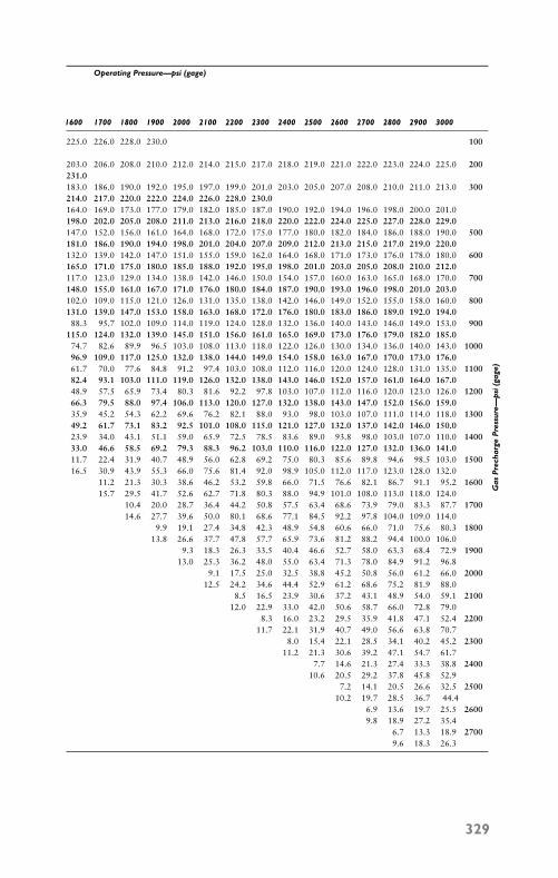
P1: FCH
GB098-07 GB093-Miller September 13, 2004 18:0 Char Count= 0
Operating Pressure—psi (gage)
1600 1700 1800 1900 2000 2100 2200 2300 2400 2500 2600 2700 2800 2900 3000
225.0 226.0 228.0 230.0 100
203.0 206.0 208.0 210.0 212.0 214.0 215.0 217.0 218.0 219.0 221.0 222.0 223.0 224.0 225.0 200231.0183.0 186.0 190.0 192.0 195.0 197.0 199.0 201.0 203.0 205.0 207.0 208.0 210.0 211.0 213.0 300214.0 217.0 220.0 222.0 224.0 226.0 228.0 230.0164.0 169.0 173.0 177.0 179.0 182.0 185.0 187.0 190.0 192.0 194.0 196.0 198.0 200.0 201.0198.0 202.0 205.0 208.0 211.0 213.0 216.0 218.0 220.0 222.0 224.0 225.0 227.0 228.0 229.0147.0 152.0 156.0 161.0 164.0 168.0 172.0 175.0 177.0 180.0 182.0 184.0 186.0 188.0 190.0 500181.0 186.0 190.0 194.0 198.0 201.0 204.0 207.0 209.0 212.0 213.0 215.0 217.0 219.0 220.0132.0 139.0 142.0 147.0 151.0 155.0 159.0 162.0 164.0 168.0 171.0 173.0 176.0 178.0 180.0 600165.0 171.0 175.0 180.0 185.0 188.0 192.0 195.0 198.0 201.0 203.0 205.0 208.0 210.0 212.0117.0 123.0 129.0 134.0 138.0 142.0 146.0 150.0 154.0 157.0 160.0 163.0 165.0 168.0 170.0 700148.0 155.0 161.0 167.0 171.0 176.0 180.0 184.0 187.0 190.0 193.0 196.0 198.0 201.0 203.0102.0 109.0 115.0 121.0 126.0 131.0 135.0 138.0 142.0 146.0 149.0 152.0 155.0 158.0 160.0 800131.0 139.0 147.0 153.0 158.0 163.0 168.0 172.0 176.0 180.0 183.0 186.0 189.0 192.0 194.088.3 95.7 102.0 109.0 114.0 119.0 124.0 128.0 132.0 136.0 140.0 143.0 146.0 149.0 153.0 900
115.0 124.0 132.0 139.0 145.0 151.0 156.0 161.0 165.0 169.0 173.0 176.0 179.0 182.0 185.074.7 82.6 89.9 96.5 103.0 108.0 113.0 118.0 122.0 126.0 130.0 134.0 136.0 140.0 143.0 100096.9 109.0 117.0 125.0 132.0 138.0 144.0 149.0 154.0 158.0 163.0 167.0 170.0 173.0 176.061.7 70.0 77.6 84.8 91.2 97.4 103.0 108.0 112.0 116.0 120.0 124.0 128.0 131.0 135.0 110082.4 93.1 103.0 111.0 119.0 126.0 132.0 138.0 143.0 146.0 152.0 157.0 161.0 164.0 167.048.9 57.5 65.9 73.4 80.3 81.6 92.2 97.8 103.0 107.0 112.0 116.0 120.0 123.0 126.0 120066.3 79.5 88.0 97.4 106.0 113.0 120.0 127.0 132.0 138.0 143.0 147.0 152.0 156.0 159.035.9 45.2 54.3 62.2 69.6 76.2 82.1 88.0 93.0 98.0 103.0 107.0 111.0 114.0 118.0 130049.2 61.7 73.1 83.2 92.5 101.0 108.0 115.0 121.0 127.0 132.0 137.0 142.0 146.0 150.023.9 34.0 43.1 51.1 59.0 65.9 72.5 78.5 83.6 89.0 93.8 98.0 103.0 107.0 110.0 140033.0 46.6 58.5 69.2 79.3 88.3 96.2 103.0 110.0 116.0 122.0 127.0 132.0 136.0 141.011.7 22.4 31.9 40.7 48.9 56.0 62.8 69.2 75.0 80.3 85.6 89.8 94.6 98.5 103.0 150016.5 30.9 43.9 55.3 66.0 75.6 81.4 92.0 98.9 105.0 112.0 117.0 123.0 128.0 132.0
11.2 21.3 30.3 38.6 46.2 53.2 59.8 66.0 71.5 76.6 82.1 86.7 91.1 95.2 160015.7 29.5 41.7 52.6 62.7 71.8 80.3 88.0 94.9 101.0 108.0 113.0 118.0 124.0
10.4 20.0 28.7 36.4 44.2 50.8 57.5 63.4 68.6 73.9 79.0 83.3 87.7 170014.6 27.7 39.6 50.0 80.1 68.6 77.1 84.5 92.2 97.8 104.0 109.0 114.0
9.9 19.1 27.4 34.8 42.3 48.9 54.8 60.6 66.0 71.0 75.6 80.3 180013.8 26.6 37.7 47.8 57.7 65.9 73.6 81.2 88.2 94.4 100.0 106.0
9.3 18.3 26.3 33.5 40.4 46.6 52.7 58.0 63.3 68.4 72.9 190013.0 25.3 36.2 48.0 55.0 63.4 71.3 78.0 84.9 91.2 96.8
9.1 17.5 25.0 32.5 38.8 45.2 50.8 56.0 61.2 66.0 200012.5 24.2 34.6 44.4 52.9 61.2 68.6 75.2 81.9 88.0
8.5 16.5 23.9 30.6 37.2 43.1 48.9 54.0 59.1 210012.0 22.9 33.0 42.0 50.6 58.7 66.0 72.8 79.0
8.3 16.0 23.2 29.5 35.9 41.8 47.1 52.4 220011.7 22.1 31.9 40.7 49.0 56.6 63.8 70.7
8.0 15.4 22.1 28.5 34.1 40.2 45.2 230011.2 21.3 30.6 39.2 47.1 54.7 61.7
7.7 14.6 21.3 27.4 33.3 38.8 240010.6 20.5 29.2 37.8 45.8 52.9
7.2 14.1 20.5 26.6 32.5 250010.2 19.7 28.5 36.7 44.4
6.9 13.6 19.7 25.5 26009.8 18.9 27.2 35.4
6.7 13.3 18.9 27009.6 18.3 26.3
Gas
Pre
char
geP
ress
ure—
psi
(gag
e)
329
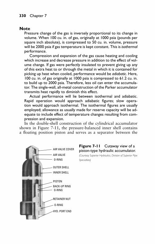
P1: FCH
GB098-07 GB093-Miller September 13, 2004 18:0 Char Count= 0
330 Chapter 7
NotePressure change of the gas is inversely proportional to its change involume. When 100 cu. in. of gas, originally at 1000 psia (pounds persquare inch absolute), is compressed to 50 cu. in. volume, pressurewill be 2000 psia if gas temperature is kept constant. This is isothermalperformance.
Compression and expansion of the gas cause heating and coolingwhich increase and decrease pressure in addition to the effect of vol-ume change. If gas were perfectly insulated to prevent giving up anyof this extra heat to or through the metal in which it is contained forpicking up heat when cooled, performance would be adiabatic. Here,100 cu. in. of gas originally at 1000 psia is compressed to 61.2 cu. in.to build up to 2000 psia. Therefore, less oil can enter the accumula-tor. The single-wall, all-metal construction of the Parker accumulatortransmits heat rapidly to diminish this effect.
Actual performance will lie between isothermal and adiabatic.Rapid operation would approach adiabatic figures; slow opera-tion would approach isothermal. The isothermal figures are usuallyemployed; allowance as usually made for reserve capacity will be ad-equate to include effect of temperature changes resulting from com-pression and expansion.In the double-shell construction of the cylindrical accumulator
shown in Figure 7-11, the pressure-balanced inner shell containsa floating position piston and serves as a separator between the
AIR VALVE COVER
AIR VALVE
O-RING
O-RING
O-RING
OUTER SHELL
INNER SHELL
PISTON
BACK-UP RING
RETAINER NUT
HYD. PORT END
Figure 7-11 Cutaway view of apiston-type hydraulic accumulator.(Courtesy Superior Hydraulics, Division of Superior Pipe
Specialties)
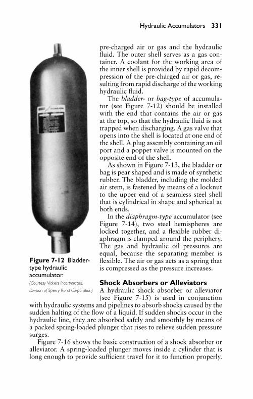
P1: FCH
GB098-07 GB093-Miller September 13, 2004 18:0 Char Count= 0
Hydraulic Accumulators 331
Figure 7-12 Bladder-type hydraulicaccumulator.(Courtesy Vickers Incorporated,
Division of Sperry Rand Corporation)
pre-charged air or gas and the hydraulicfluid. The outer shell serves as a gas con-tainer. A coolant for the working area ofthe inner shell is provided by rapid decom-pression of the pre-charged air or gas, re-sulting from rapid discharge of the workinghydraulic fluid.
The bladder- or bag-type of accumula-tor (see Figure 7-12) should be installedwith the end that contains the air or gasat the top, so that the hydraulic fluid is nottrapped when discharging. A gas valve thatopens into the shell is located at one end ofthe shell. A plug assembly containing an oilport and a poppet valve is mounted on theopposite end of the shell.
As shown in Figure 7-13, the bladder orbag is pear shaped and is made of syntheticrubber. The bladder, including the moldedair stem, is fastened by means of a locknutto the upper end of a seamless steel shellthat is cylindrical in shape and spherical atboth ends.
In the diaphragm-type accumulator (seeFigure 7-14), two steel hemispheres arelocked together, and a flexible rubber di-aphragm is clamped around the periphery.The gas and hydraulic oil pressures areequal, because the separating member isflexible. The air or gas acts as a spring thatis compressed as the pressure increases.
Shock Absorbers or AlleviatorsA hydraulic shock absorber or alleviator(see Figure 7-15) is used in conjunction
with hydraulic systems and pipelines to absorb shocks caused by thesudden halting of the flow of a liquid. If sudden shocks occur in thehydraulic line, they are absorbed safely and smoothly by means ofa packed spring-loaded plunger that rises to relieve sudden pressuresurges.
Figure 7-16 shows the basic construction of a shock absorber oralleviator. A spring-loaded plunger moves inside a cylinder that islong enough to provide sufficient travel for it to function properly.
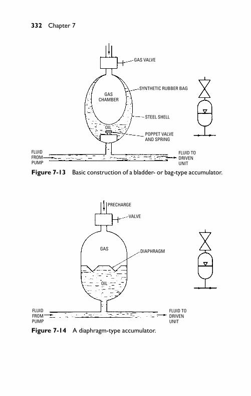
P1: FCH
GB098-07 GB093-Miller September 13, 2004 18:0 Char Count= 0
332 Chapter 7
GAS VALVE
SYNTHETIC RUBBER BAG
STEEL SHELL
POPPET VALVEAND SPRING
FLUID TODRIVENUNIT
FLUID FROMPUMP
GASCHAMBER
OIL
Figure 7-13 Basic construction of a bladder- or bag-type accumulator.
PRECHARGE
VALVE
DIAPHRAGMGAS
OIL
FLUIDFROMPUMP
FLUID TODRIVENUNIT
Figure 7-14 A diaphragm-type accumulator.
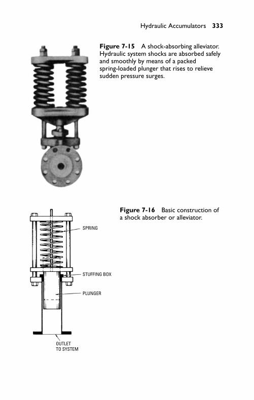
P1: FCH
GB098-07 GB093-Miller September 13, 2004 18:0 Char Count= 0
Hydraulic Accumulators 333
Figure 7-15 A shock-absorbing alleviator.Hydraulic system shocks are absorbed safelyand smoothly by means of a packedspring-loaded plunger that rises to relievesudden pressure surges.
SPRING
STUFFING BOX
PLUNGER
OUTLETTO SYSTEM
Figure 7-16 Basic construction ofa shock absorber or alleviator.
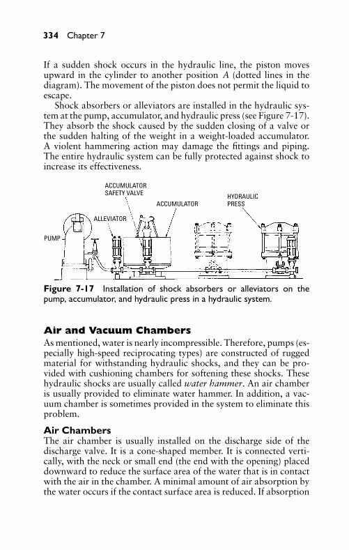
P1: FCH
GB098-07 GB093-Miller September 13, 2004 18:0 Char Count= 0
334 Chapter 7
If a sudden shock occurs in the hydraulic line, the piston movesupward in the cylinder to another position A (dotted lines in thediagram). The movement of the piston does not permit the liquid toescape.
Shock absorbers or alleviators are installed in the hydraulic sys-tem at the pump, accumulator, and hydraulic press (see Figure 7-17).They absorb the shock caused by the sudden closing of a valve orthe sudden halting of the weight in a weight-loaded accumulator.A violent hammering action may damage the fittings and piping.The entire hydraulic system can be fully protected against shock toincrease its effectiveness.
ACCUMULATORSAFETY VALVE
ACCUMULATORHYDRAULICPRESS
ALLEVIATOR
PUMP
Figure 7-17 Installation of shock absorbers or alleviators on thepump, accumulator, and hydraulic press in a hydraulic system.
Air and Vacuum ChambersAs mentioned, water is nearly incompressible. Therefore, pumps (es-pecially high-speed reciprocating types) are constructed of ruggedmaterial for withstanding hydraulic shocks, and they can be pro-vided with cushioning chambers for softening these shocks. Thesehydraulic shocks are usually called water hammer. An air chamberis usually provided to eliminate water hammer. In addition, a vac-uum chamber is sometimes provided in the system to eliminate thisproblem.
Air ChambersThe air chamber is usually installed on the discharge side of thedischarge valve. It is a cone-shaped member. It is connected verti-cally, with the neck or small end (the end with the opening) placeddownward to reduce the surface area of the water that is in contactwith the air in the chamber. A minimal amount of air absorption bythe water occurs if the contact surface area is reduced. If absorption
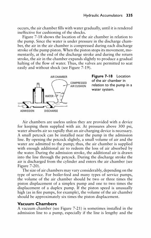
P1: FCH
GB098-07 GB093-Miller September 13, 2004 18:0 Char Count= 0
Hydraulic Accumulators 335
occurs, the air chamber fills with water gradually, until it is renderedineffective for cushioning of the shocks.
Figure 7-18 shows the location of the air chamber in relation tothe pump. Since the water is under pressure in the discharge cham-ber, the air in the air chamber is compressed during each dischargestroke of the pump piston. When the piston stops its movement, mo-mentarily, at the end of the discharge stroke and during the returnstroke, the air in the chamber expands slightly to produce a gradualhalting of the flow of water. Thus, the valves are permitted to seateasily and without shock (see Figure 7-19).
ADMISSION DISCHARGE
WATER
COMPRESSEDAIR CUSHION
AIR CHAMBER Figure 7-18 Locationof the air chamber inrelation to the pump in awater system.
Air chambers are useless unless they are provided with a devicefor keeping them supplied with air. At pressures above 300 psi,water absorbs air so rapidly that an air-charging device is necessary.A small petcock can be installed near the pump in the admissionline. By opening the petcock slightly, a small volume of air and thewater are admitted to the pump; thus, the air chamber is suppliedwith enough additional air to redeem the loss of air absorbed bythe water. During the admission stroke, the additional air is drawninto the line through the petcock. During the discharge stroke theair is discharged from the cylinder and enters the air chamber (seeFigure 7-20).
The size of air chambers may vary considerably, depending on thetype of service. For boiler-feed and many types of service pumps,the volume of the air chamber should be two or three times thepiston displacement of a simplex pump and one to two times thedisplacement of a duplex pump. If the piston speed is unusuallyhigh (as in fire pumps, for example), the volume of the air chambershould be approximately six times the piston displacement.
Vacuum ChambersA vacuum chamber (see Figure 7-21) is sometimes installed in theadmission line to a pump, especially if the line is lengthy and the
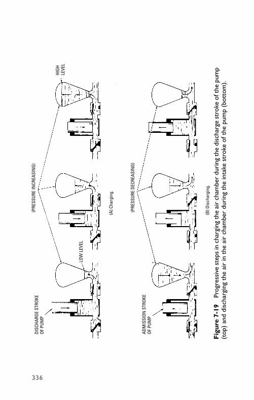
P1: FCH
GB098-07 GB093-Miller September 13, 2004 18:0 Char Count= 0
DISC
HARG
E ST
ROKE
OF P
UMP
(PRE
SSUR
E IN
CREA
SIN
G)
(PRE
SSUR
E DE
CREA
SIN
G)
LOW
LEV
EL
(A) C
harg
ing.
(B) D
isch
argi
ng.
ADM
ISSI
ON S
TROK
EOF
PUM
P
HIGH
LEVE
L
Fig
ure
7-19
Prog
ress
ive
step
sin
char
ging
the
air
cham
ber
duri
ngth
edi
scha
rge
stro
keo f
the
pum
p(t
op)
and
disc
harg
ing
the
air
inth
eai
rch
ambe
rdu
ring
the
inta
kest
roke
ofth
epu
mp
(bot
tom
).
336
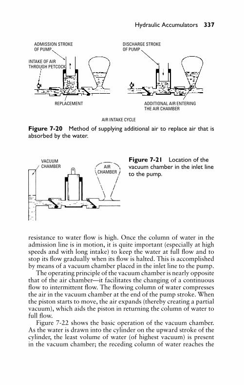
P1: FCH
GB098-07 GB093-Miller September 13, 2004 18:0 Char Count= 0
Hydraulic Accumulators 337
ADMISSION STROKEOF PUMP
INTAKE OF AIRTHROUGH PETCOCK
REPLACEMENT
AIR INTAKE CYCLE
ADDITIONAL AIR ENTERINGTHE AIR CHAMBER
DISCHARGE STROKEOF PUMP
Figure 7-20 Method of supplying additional air to replace air that isabsorbed by the water.
AIRCHAMBER
VACUUMCHAMBER
Figure 7-21 Location of thevacuum chamber in the inlet lineto the pump.
resistance to water flow is high. Once the column of water in theadmission line is in motion, it is quite important (especially at highspeeds and with long intake) to keep the water at full flow and tostop its flow gradually when its flow is halted. This is accomplishedby means of a vacuum chamber placed in the inlet line to the pump.
The operating principle of the vacuum chamber is nearly oppositethat of the air chamber—it facilitates the changing of a continuousflow to intermittent flow. The flowing column of water compressesthe air in the vacuum chamber at the end of the pump stroke. Whenthe piston starts to move, the air expands (thereby creating a partialvacuum), which aids the piston in returning the column of water tofull flow.
Figure 7-22 shows the basic operation of the vacuum chamber.As the water is drawn into the cylinder on the upward stroke of thecylinder, the least volume of water (of highest vacuum) is presentin the vacuum chamber; the receding column of water reaches the
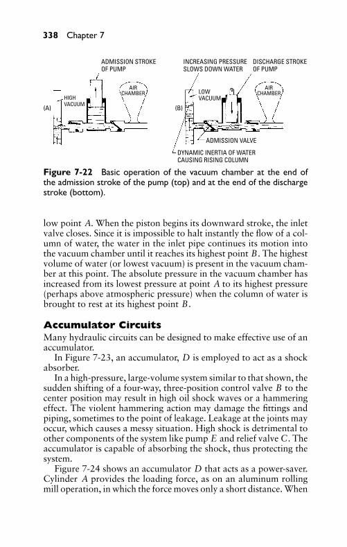
P1: FCH
GB098-07 GB093-Miller September 13, 2004 18:0 Char Count= 0
338 Chapter 7
ADMISSION STROKEOF PUMP
AIRCHAMBER
INCREASING PRESSURESLOWS DOWN WATER
DISCHARGE STROKEOF PUMP
AIRCHAMBERLOW
VACUUM
(B)(A)
ADMISSION VALVE
DYNAMIC INERTIA OF WATERCAUSING RISING COLUMN
HIGHVACUUM
Figure 7-22 Basic operation of the vacuum chamber at the end ofthe admission stroke of the pump (top) and at the end of the dischargestroke (bottom).
low point A. When the piston begins its downward stroke, the inletvalve closes. Since it is impossible to halt instantly the flow of a col-umn of water, the water in the inlet pipe continues its motion intothe vacuum chamber until it reaches its highest point B. The highestvolume of water (or lowest vacuum) is present in the vacuum cham-ber at this point. The absolute pressure in the vacuum chamber hasincreased from its lowest pressure at point A to its highest pressure(perhaps above atmospheric pressure) when the column of water isbrought to rest at its highest point B.
Accumulator CircuitsMany hydraulic circuits can be designed to make effective use of anaccumulator.
In Figure 7-23, an accumulator, D is employed to act as a shockabsorber.
In a high-pressure, large-volume system similar to that shown, thesudden shifting of a four-way, three-position control valve B to thecenter position may result in high oil shock waves or a hammeringeffect. The violent hammering action may damage the fittings andpiping, sometimes to the point of leakage. Leakage at the joints mayoccur, which causes a messy situation. High shock is detrimental toother components of the system like pump E and relief valve C. Theaccumulator is capable of absorbing the shock, thus protecting thesystem.
Figure 7-24 shows an accumulator D that acts as a power-saver.Cylinder A provides the loading force, as on an aluminum rollingmill operation, in which the force moves only a short distance. When
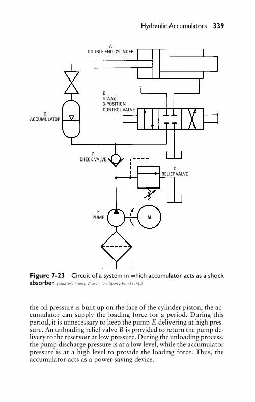
P1: FCH
GB098-07 GB093-Miller September 13, 2004 18:0 Char Count= 0
Hydraulic Accumulators 339
ADOUBLE END CYLINDER
B4-WAY,3-POSITIONCONTROL VALVE
DACCUMULATOR
FCHECK VALVE
CRELIEF VALVE
ME
PUMP
Figure 7-23 Circuit of a system in which accumulator acts as a shockabsorber. (Courtesy Sperry Vickers, Div. Sperry Rand Corp.)
the oil pressure is built up on the face of the cylinder piston, the ac-cumulator can supply the loading force for a period. During thisperiod, it is unnecessary to keep the pump E delivering at high pres-sure. An unloading relief valve B is provided to return the pump de-livery to the reservoir at low pressure. During the unloading process,the pump discharge pressure is at a low level, while the accumulatorpressure is at a high level to provide the loading force. Thus, theaccumulator acts as a power-saving device.
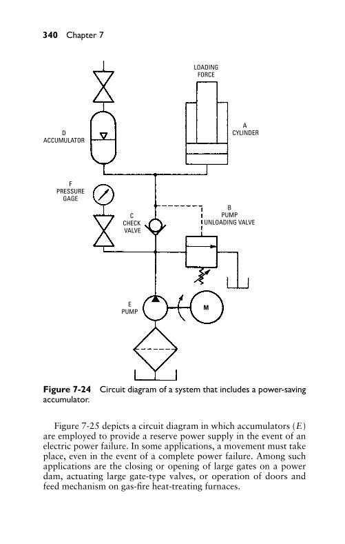
P1: FCH
GB098-07 GB093-Miller September 13, 2004 18:0 Char Count= 0
340 Chapter 7
A CYLINDERD
ACCUMULATOR
FPRESSURE
GAGE
CCHECK VALVE
MEPUMP
BPUMP
UNLOADING VALVE
LOADINGFORCE
Figure 7-24 Circuit diagram of a system that includes a power-savingaccumulator.
Figure 7-25 depicts a circuit diagram in which accumulators (E)are employed to provide a reserve power supply in the event of anelectric power failure. In some applications, a movement must takeplace, even in the event of a complete power failure. Among suchapplications are the closing or opening of large gates on a powerdam, actuating large gate-type valves, or operation of doors andfeed mechanism on gas-fire heat-treating furnaces.
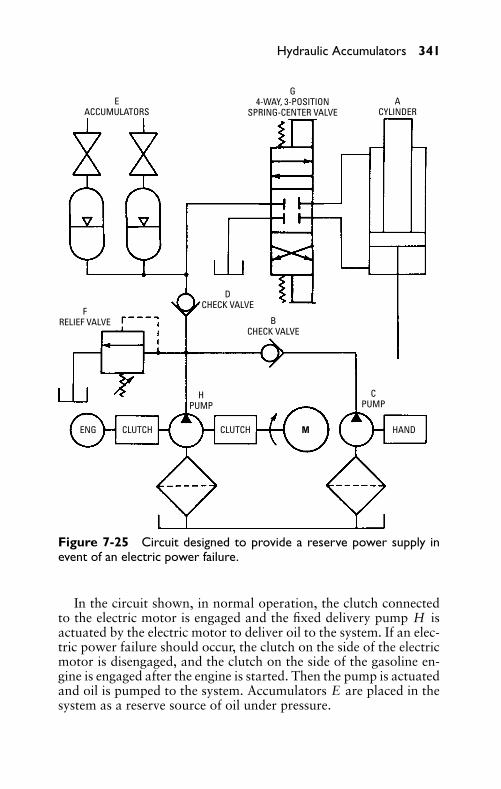
P1: FCH
GB098-07 GB093-Miller September 13, 2004 18:0 Char Count= 0
Hydraulic Accumulators 341
EACCUMULATORS
G4-WAY, 3-POSITION
SPRING-CENTER VALVEA
CYLINDER
FRELIEF VALVE
DCHECK VALVE
BCHECK VALVE
HPUMP
CLUTCH CLUTCHENG M HAND
CPUMP
Figure 7-25 Circuit designed to provide a reserve power supply inevent of an electric power failure.
In the circuit shown, in normal operation, the clutch connectedto the electric motor is engaged and the fixed delivery pump H isactuated by the electric motor to deliver oil to the system. If an elec-tric power failure should occur, the clutch on the side of the electricmotor is disengaged, and the clutch on the side of the gasoline en-gine is engaged after the engine is started. Then the pump is actuatedand oil is pumped to the system. Accumulators E are placed in thesystem as a reserve source of oil under pressure.
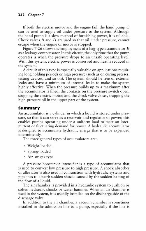
P1: FCH
GB098-07 GB093-Miller September 13, 2004 18:0 Char Count= 0
342 Chapter 7
If both the electric motor and the engine fail, the hand pump Ccan be used to supply oil under pressure to the system. Althoughthe hand pump is a slow method of furnishing power, it is reliable.Check valves B and D are used so that oil, under pressure, cannotescape when the engine or motor is stopped.
Figure 7-26 shows the employment of a bag-type accumulator Eas a leakage compensator. In this circuit, the only time that the pumpoperates is when the pressure drops to an unsafe operating level.With this system, electric power is conserved and heat is reduced inthe system.
A circuit of this type is especially valuable on applications requir-ing long holding periods or high pressure (such as on curing presses,testing devices, and so on). The system should be free of externalleaks and have a minimum of internal leaks to make the systemhighly effective. When the pressure builds up to a maximum afterthe accumulator is filled, the contacts on the pressure switch open,stopping the electric motor, and the check valve closes, trapping thehigh-pressure oil in the upper part of the system.
SummaryAn accumulator is a cylinder in which a liquid is stored under pres-sure, so that it can serve as a reservoir and regulator of power; thisenables pumps operating under a uniform load to meet an inter-mittent or fluctuating demand for power. A hydraulic accumulatoris designed to accumulate hydraulic energy that is to be expendedintermittently.
The three general types of accumulators are:
� Weight-loaded� Spring-loaded� Air- or gas-type
A pressure booster or intensifier is a type of accumulator thatis used to convert low pressure to high pressure. A shock absorberor alleviator is also used in conjunction with hydraulic systems andpipelines to absorb sudden shocks caused by the sudden halting ofthe flow of a liquid.
The air chamber is provided in a hydraulic system to cushion orsoften hydraulic shocks or water hammer. When an air chamber isused in the system, it is usually installed on the discharge side of thedischarge valve.
In addition to the air chamber, a vacuum chamber is sometimesinstalled in the admission line to a pump, especially if the line is
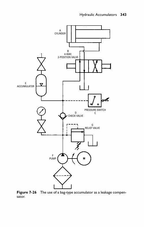
P1: FCH
GB098-07 GB093-Miller September 13, 2004 18:0 Char Count= 0
Hydraulic Accumulators 343
ACYLINDER
B4-WAY,
2-POSITION VALVE
EACCUMULATOR
PRESSURE SWITCHCD
CHECK VALVE
GRELIEF VALVE
MF
PUMP
Figure 7-26 The use of a bag-type accumulator as a leakage compen-sator.
P1: FCH
GB098-07 GB093-Miller September 13, 2004 18:0 Char Count= 0
344 Chapter 7
lengthy and the resistance to water flow is high. The purpose of thevacuum chamber is to keep the water at full flow and to stop it grad-ually when its flow is halted. This facilitates changing a continuousflow of water to an intermittent flow.
Review Questions1. What is the purpose of the hydraulic accumulator?2. What is the purpose of a pressure booster or intensifier in the
hydraulic system?3. What is the purpose of an alleviator or shock absorber in the
hydraulic system?4. Describe the basic operation of an air chamber in a hydraulic
system.5. Describe the basic operation of a vacuum chamber in a hy-
draulic system.6. What are the essential parts of the weight-loaded accumulator?7. List the three types of hydraulic accumulators.8. What does a pressure converter do?9. Draw the symbol for an air or gas accumulator.
10. What is the cubic inch displacement of 1 gallon?11. Describe the bladder or bag type accumulator.12. What is another name for a shock absorber?
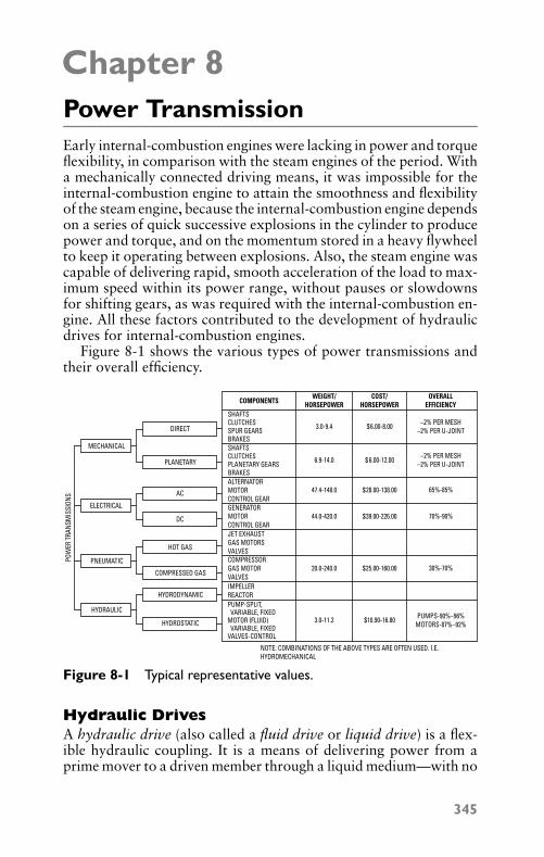
P1: JYC
GB098-08 GB098-Miller September 13, 2004 19:31 Char Count= 0
Chapter 8Power TransmissionEarly internal-combustion engines were lacking in power and torqueflexibility, in comparison with the steam engines of the period. Witha mechanically connected driving means, it was impossible for theinternal-combustion engine to attain the smoothness and flexibilityof the steam engine, because the internal-combustion engine dependson a series of quick successive explosions in the cylinder to producepower and torque, and on the momentum stored in a heavy flywheelto keep it operating between explosions. Also, the steam engine wascapable of delivering rapid, smooth acceleration of the load to max-imum speed within its power range, without pauses or slowdownsfor shifting gears, as was required with the internal-combustion en-gine. All these factors contributed to the development of hydraulicdrives for internal-combustion engines.
Figure 8-1 shows the various types of power transmissions andtheir overall efficiency.
POW
ER T
RANS
MIS
SION
S
MECHANICAL
DIRECT
COMPONENTSWEIGHT/
HORSEPOWERCOST/
HORSEPOWEROVERALL
EFFICIENCY
PLANETARY
AC
DC
HOT GAS
COMPRESSED GAS
HYDRODYNAMIC
HYDROSTATIC
ELECTRICAL
PNEUMATIC
HYDRAULIC
SHAFTSCLUTCHESSPUR GEARSBRAKESSHAFTSCLUTCHESPLANETARY GEARSBRAKESALTERNATORMOTORCONTROL GEARGENERATORMOTORCONTROL GEARJET EXHAUSTGAS MOTORSVALVESCOMPRESSORGAS MOTORVALVESIMPELLERREACTORPUMP-SPLIT, VARIABLE, FIXEDMOTOR (FLUID) VARIABLE, FIXEDVALVES-CONTROL
3.0-9.4 –2% PER MESH–2% PER U-JOINT
–2% PER MESH–2% PER U-JOINT
65%-85%
70%-90%
30%-70%
PUMPS-90%–96%MOTORS-87%–92%
6.9-14.0
47.4-148.0
44.0-420.0
20.0-240.0
3.0-11.2
$6.00-8.00
$ 6.00-12.00
$28.00-138.00
$39.00-226.00
$25.00-160.00
$10.90-16.80
NOTE: COMBINATIONS OF THE ABOVE TYPES ARE OFTEN USED. I.E.HYDROMECHANICAL
Figure 8-1 Typical representative values.
Hydraulic DrivesA hydraulic drive (also called a fluid drive or liquid drive) is a flex-ible hydraulic coupling. It is a means of delivering power from aprime mover to a driven member through a liquid medium—with no
345
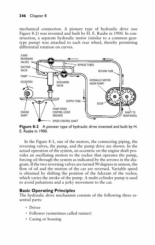
P1: JYC
GB098-08 GB098-Miller September 13, 2004 19:31 Char Count= 0
346 Chapter 8
mechanical connection. A pioneer type of hydraulic drive (seeFigure 8-2) was invented and built by H. E. Raabe in 1900. In con-struction, a separate hydraulic motor (similar to a common gear-type pump) was attached to each rear wheel, thereby permittingdifferential rotation on curves.
3-WAYREVERSINGVALVES
SUCTIONVALVE
PUMP
ECCENTRIC
ENGINESHAFT
PUMP SPEEDCONTROL LEVER(ROCKER)
SPEED CONTROL SHAFT
SUPPLY TUBE
DISCHARGEVALVE
BYPASS TUBES
RETURN TUBE
HYDRAULIC MOTOR(GEAR PUMP)
IDLER
SHAFT TOREAR WHEEL
Figure 8-2 A pioneer type of hydraulic drive invented and built by H.E. Raabe in 1900.
In the Figure 8-1, one of the motors, the connecting piping, thereversing valves, the pump, and the pump drive are shown. In theactual operation of the system, an eccentric on the engine shaft pro-vides an oscillating motion to the rocker that operates the pump,forcing oil through the system as indicated by the arrows in the dia-gram. If the two reversing valves are turned 90 degrees in unison, theflow of oil and the motion of the car are reversed. Variable speedis obtained by shifting the position of the fulcrum of the rocker,which varies the stroke of the pump. A multi-cylinder pump is usedto avoid pulsations and a jerky movement to the car.
Basic Operating PrinciplesThe hydraulic drive mechanism consists of the following three es-sential parts:
� Driver� Follower (sometimes called runner)� Casing or housing
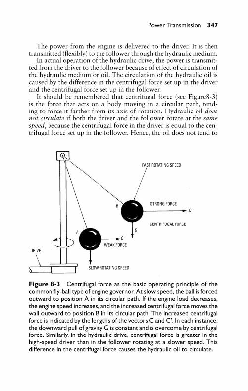
P1: JYC
GB098-08 GB098-Miller September 13, 2004 19:31 Char Count= 0
Power Transmission 347
The power from the engine is delivered to the driver. It is thentransmitted (flexibly) to the follower through the hydraulic medium.
In actual operation of the hydraulic drive, the power is transmit-ted from the driver to the follower because of effect of circulation ofthe hydraulic medium or oil. The circulation of the hydraulic oil iscaused by the difference in the centrifugal force set up in the driverand the centrifugal force set up in the follower.
It should be remembered that centrifugal force (see Figure8-3)is the force that acts on a body moving in a circular path, tend-ing to force it farther from its axis of rotation. Hydraulic oil doesnot circulate if both the driver and the follower rotate at the samespeed, because the centrifugal force in the driver is equal to the cen-trifugal force set up in the follower. Hence, the oil does not tend to
CENTRIFUGAL FORCE
STRONG FORCE
C
DRIVE
SLOW ROTATING SPEED
FAST ROTATING SPEED
WEAK FORCE
A
B
G
C‘
Figure 8-3 Centrifugal force as the basic operating principle of thecommon fly-ball type of engine governor. At slow speed, the ball is forcedoutward to position A in its circular path. If the engine load decreases,the engine speed increases, and the increased centrifugal force moves thewall outward to position B in its circular path. The increased centrifugalforce is indicated by the lengths of the vectors C and C’. In each instance,the downward pull of gravity G is constant and is overcome by centrifugalforce. Similarly, in the hydraulic drive, centrifugal force is greater in thehigh-speed driver than in the follower rotating at a slower speed. Thisdifference in the centrifugal force causes the hydraulic oil to circulate.
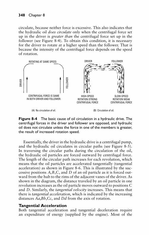
P1: JYC
GB098-08 GB098-Miller September 13, 2004 19:31 Char Count= 0
348 Chapter 8
circulate, because neither force is excessive. This also indicates thatthe hydraulic oil does circulate only when the centrifugal force setup in the driver is greater than the centrifugal force set up in thefollower (see Figure 8-4). To obtain this condition, it is necessaryfor the driver to rotate at a higher speed than the follower. That isbecause the intensity of the centrifugal force depends on the speedof rotation.
(A) No circulation of oil.
DRIV
ER
DRIVER
FOLL
OWER
FOLLOWER
CENTRIFUGAL FORCE IS SAMEIN BOTH DRIVER AND FOLLOWER.
HIGH-SPEEDROTATION STRONG
CENTRIFUGAL FORCE
SLOW-SPEEDROTATION WEAK
CENTRIFUGAL FORCE
(B) Circulation of oil.
ROTATING AT SAME SPEED.
Figure 8-4 The basic cause of oil circulation in a hydraulic drive. Thecentrifugal forces in the driver and follower are opposed, and hydraulicoil does not circulate unless the force in one of the members is greater,the result of increased rotation speed.
Essentially, the driver in the hydraulic drive is a centrifugal pump,and the hydraulic oil circulates in circular paths (see Figure 8-5).In traversing the circular paths during the circulation of the oil,the hydraulic oil particles are forced outward by centrifugal force.The length of the circular path increases for each revolution, whichmeans that the oil particles are accelerated tangentially (tangentialacceleration) as shown in Figure 8-6. This is illustrated by the suc-cessive positions A,B,C, and D of an oil particle as it is forced out-ward from the hub to the rims of the adjacent vanes of the driver. Asshown in the diagram, the distance traveled by an oil particle in onerevolution increases as the oil particle moves outward to positions Cand D. Similarly, the tangential velocity increases. This means thatthere is tangential acceleration, which is indicated by the increasingdistances Aa,Bb,Cc, and Dd from the axis of rotation.
Tangential AccelerationBoth tangential acceleration and tangential deceleration requirean expenditure of energy (supplied by the engine). Most of the
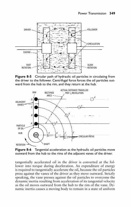
P1: JYC
GB098-08 GB098-Miller September 13, 2004 19:31 Char Count= 0
Power Transmission 349
DRIVER
CASING
FASTROTATION
SLOWROTATION
CIRCULATION
FOLLOWER
Figure 8-5 Circular path of hydraulic oil particles in circulating fromthe driver to the follower. Centrifugal force forces the oil particles out-ward from the hub to the rim, and they return at the hub.
RIM RECTIFIEDARCS
ACTUAL DISTANCE TRAVELLEDPER 1/4 REVOLUTION
d
ADJACENTVANES
PARTICLEOF OIL
HUB
ROTATION SHAFT
CIRCULAR PATHS
A
B
C
D
a' b' c' d'
a
b
c
Figure 8-6 Tangential acceleration as the hydraulic oil particles moveoutward from the hub to the rims of the adjacent vanes of the driver.
tangentially accelerated oil in the driver is converted at the fol-lower into torque during deceleration. An expenditure of energyis required to tangentially accelerate the oil, because the oil particlespress against the vanes of the driver as they move outward. Strictlyspeaking, the vane presses against the oil particles to overcome thedynamic inertia resulting from acceleration of its tangential velocityas the oil moves outward from the hub to the rim of the vane. Dy-namic inertia causes a moving body to remain in a state of uniform
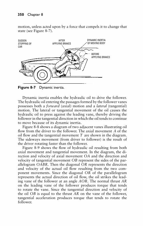
P1: JYC
GB098-08 GB098-Miller September 13, 2004 19:31 Char Count= 0
350 Chapter 8
motion, unless acted upon by a force that compels it to change thatstate (see Figure 8-7).
SUDDENSTOPPING OFCAR
AFTERAPPLYING BRAKES
DYNAMIC INERTIAOF MOVING BODY
BEFOREAPPLYING BRAKES
Figure 8-7 Dynamic inertia.
Dynamic inertia enables the hydraulic oil to drive the follower.The hydraulic oil entering the passages formed by the follower vanespossesses both a forward (axial) motion and a lateral (tangential)motion. The lateral or tangential movement of the oil causes thehydraulic oil to press against the leading vane, thereby driving thefollower in the tangential direction in which the oil tends to continueto move because of its dynamic inertia.
Figure 8-8 shows a diagram of two adjacent vanes illustrating oilflow from the driver to the follower. The axial movement A of theoil flow and the tangential movement T are shown in the diagram.The sideways movement (from driver to follower) is the result ofthe driver rotating faster than the follower.
Figure 8-9 shows the flow of hydraulic oil resulting from bothaxial movement and tangential movement. In the diagram, the di-rection and velocity of axial movement OA and the direction andvelocity of tangential movement OB represent the sides of the par-allelogram OABR. Then the diagonal OR represents the directionand velocity of the actual oil flow resulting from the two com-ponent movements. Since the diagonal OR of the parallelogramrepresents the actual direction of oil flow, the oil strikes the lead-ing vane of the follower at an angle AOR. The normal thrust ARon the leading vane of the follower produces torque that tendsto rotate the vane. Since the tangential direction and velocity ofthe oil OB is equal to the thrust AR on the vane of the follower,tangential acceleration produces torque that tends to rotate thefollower.
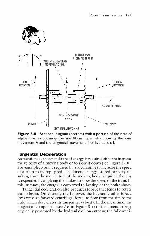
P1: JYC
GB098-08 GB098-Miller September 13, 2004 19:31 Char Count= 0
Power Transmission 351
TANGENTIAL (LATERAL)MOVEMENT OF OIL
LEADING VANERECEIVING THRUST
SLOWROTATION
FASTROTATION
AXIS OF ROTATION
AXIAL MOVEMENTOF OIL
FOLLOWERSECTIONAL VIEW ON AB
DRIVER
T
A B
Figure 8-8 Sectional diagram (bottom) with a portion of the rims ofadjacent vanes cut away (on line AB in upper left), showing the axialmovement A and the tangential movement T of hydraulic oil.
Tangential DecelerationAs mentioned, an expenditure of energy is required either to increasethe velocity of a moving body or to slow it down (see Figure 8-10).For example, work is required by a locomotive to increase the speedof a train to its top speed. The kinetic energy (stored capacity re-sulting from the momentum of the moving body) acquired therebyis expended by applying the brakes to slow the speed of the train. Inthis instance, the energy is converted to heating of the brake shoes.
Tangential deceleration also produces torque that tends to rotatethe follower. On entering the follower, the hydraulic oil is forced(by excessive forward centrifugal force) to flow from the rim to thehub, which decelerates its tangential velocity. In the meantime, thetangential component (see AR in Figure 8-9) of the kinetic energyoriginally possessed by the hydraulic oil on entering the follower is
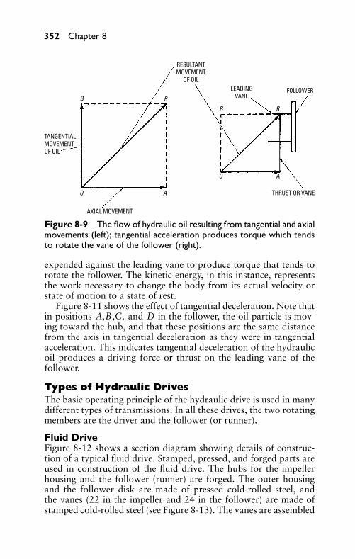
P1: JYC
GB098-08 GB098-Miller September 13, 2004 19:31 Char Count= 0
352 Chapter 8
BB
RR
O
O
A
A
RESULTANTMOVEMENT
OF OIL
TANGENTIALMOVEMENTOF OIL
AXIAL MOVEMENT
LEADINGVANE
THRUST OR VANE
FOLLOWER
Figure 8-9 The flow of hydraulic oil resulting from tangential and axialmovements (left); tangential acceleration produces torque which tendsto rotate the vane of the follower (right).
expended against the leading vane to produce torque that tends torotate the follower. The kinetic energy, in this instance, representsthe work necessary to change the body from its actual velocity orstate of motion to a state of rest.
Figure 8-11 shows the effect of tangential deceleration. Note thatin positions A,B,C, and D in the follower, the oil particle is mov-ing toward the hub, and that these positions are the same distancefrom the axis in tangential deceleration as they were in tangentialacceleration. This indicates tangential deceleration of the hydraulicoil produces a driving force or thrust on the leading vane of thefollower.
Types of Hydraulic DrivesThe basic operating principle of the hydraulic drive is used in manydifferent types of transmissions. In all these drives, the two rotatingmembers are the driver and the follower (or runner).
Fluid DriveFigure 8-12 shows a section diagram showing details of construc-tion of a typical fluid drive. Stamped, pressed, and forged parts areused in construction of the fluid drive. The hubs for the impellerhousing and the follower (runner) are forged. The outer housingand the follower disk are made of pressed cold-rolled steel, andthe vanes (22 in the impeller and 24 in the follower) are made ofstamped cold-rolled steel (see Figure 8-13). The vanes are assembled
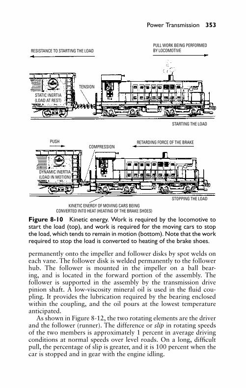
P1: JYC
GB098-08 GB098-Miller September 13, 2004 19:31 Char Count= 0
Power Transmission 353
RESISTANCE TO STARTING THE LOAD
TENSION
STATIC INERTIA(LOAD AT REST)
PULL WORK BEING PERFORMEDBY LOCOMOTIVE
STARTING THE LOAD
RETARDING FORCE OF THE BRAKECOMPRESSION
PUSH
DYNAMIC INERTIA(LOAD IN MOTION)
STOPPING THE LOADKINETIC ENERGY OF MOVING CARS BEING
CONVERTED INTO HEAT (HEATING OF THE BRAKE SHOES)
Figure 8-10 Kinetic energy. Work is required by the locomotive tostart the load (top), and work is required for the moving cars to stopthe load, which tends to remain in motion (bottom). Note that the workrequired to stop the load is converted to heating of the brake shoes.
permanently onto the impeller and follower disks by spot welds oneach vane. The follower disk is welded permanently to the followerhub. The follower is mounted in the impeller on a ball bear-ing, and is located in the forward portion of the assembly. Thefollower is supported in the assembly by the transmission drivepinion shaft. A low-viscosity mineral oil is used in the fluid cou-pling. It provides the lubrication required by the bearing enclosedwithin the coupling, and the oil pours at the lowest temperatureanticipated.
As shown in Figure 8-12, the two rotating elements are the driverand the follower (runner). The difference or slip in rotating speedsof the two members is approximately 1 percent in average drivingconditions at normal speeds over level roads. On a long, difficultpull, the percentage of slip is greater, and it is 100 percent when thecar is stopped and in gear with the engine idling.
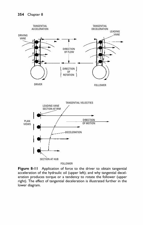
P1: JYC
GB098-08 GB098-Miller September 13, 2004 19:31 Char Count= 0
354 Chapter 8
TANGENTIALDECELERATION
TANGENTIALACCELERATION
DRIVINGVANE
DRIVER
DIRECTION OF
ROTATION
DIRECTION OF FLOW
FOLLOWER
TANGENTIAL VELOCITIESLEADING VANESECTION AT RIM
PLANVIEWS
DECELERATION
DIRECTIONOF MOTION
SECTION AT HUB
FOLLOWER
LEADINGVANE
A
A
B
BC
C
D
D
Figure 8-11 Application of force to the driver to obtain tangentialacceleration of the hydraulic oil (upper left); and why tangential decel-eration produces torque or a tendency to rotate the follower (upperright). The effect of tangential deceleration is illustrated further in thelower diagram.
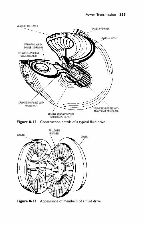
P1: JYC
GB098-08 GB098-Miller September 13, 2004 19:31 Char Count= 0
Power Transmission 355
PATH OF OIL WHENENGINE IS DRIVING
FLY WHEEL AND RINGGEAR ASSEMBLY
SPLINES ENGAGING WITHMAIN SHAFT
SPLINES ENGAGING WITHINTERMEDIATE SHAFT
SPLINES ENGAGING WITHFRONT UNIT DRIVE GEAR
VANES OF DRIVERVANES OF FOLLOWER
FLYWHEEL COVER
Figure 8-12 Construction details of a typical fluid drive.
DRIVER
FOLLOWER(RUNNER)
COVER
Figure 8-13 Appearance of members of a fluid drive.
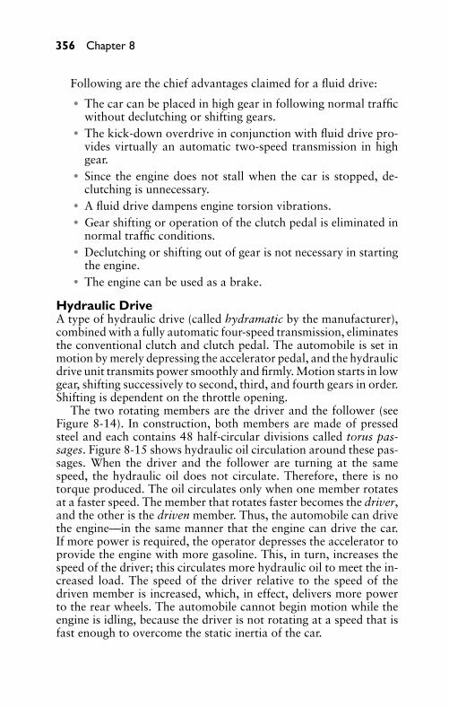
P1: JYC
GB098-08 GB098-Miller September 13, 2004 19:31 Char Count= 0
356 Chapter 8
Following are the chief advantages claimed for a fluid drive:� The car can be placed in high gear in following normal traffic
without declutching or shifting gears.� The kick-down overdrive in conjunction with fluid drive pro-
vides virtually an automatic two-speed transmission in highgear.
� Since the engine does not stall when the car is stopped, de-clutching is unnecessary.
� A fluid drive dampens engine torsion vibrations.� Gear shifting or operation of the clutch pedal is eliminated in
normal traffic conditions.� Declutching or shifting out of gear is not necessary in starting
the engine.� The engine can be used as a brake.
Hydraulic DriveA type of hydraulic drive (called hydramatic by the manufacturer),combined with a fully automatic four-speed transmission, eliminatesthe conventional clutch and clutch pedal. The automobile is set inmotion by merely depressing the accelerator pedal, and the hydraulicdrive unit transmits power smoothly and firmly. Motion starts in lowgear, shifting successively to second, third, and fourth gears in order.Shifting is dependent on the throttle opening.
The two rotating members are the driver and the follower (seeFigure 8-14). In construction, both members are made of pressedsteel and each contains 48 half-circular divisions called torus pas-sages. Figure 8-15 shows hydraulic oil circulation around these pas-sages. When the driver and the follower are turning at the samespeed, the hydraulic oil does not circulate. Therefore, there is notorque produced. The oil circulates only when one member rotatesat a faster speed. The member that rotates faster becomes the driver,and the other is the driven member. Thus, the automobile can drivethe engine—in the same manner that the engine can drive the car.If more power is required, the operator depresses the accelerator toprovide the engine with more gasoline. This, in turn, increases thespeed of the driver; this circulates more hydraulic oil to meet the in-creased load. The speed of the driver relative to the speed of thedriven member is increased, which, in effect, delivers more powerto the rear wheels. The automobile cannot begin motion while theengine is idling, because the driver is not rotating at a speed that isfast enough to overcome the static inertia of the car.
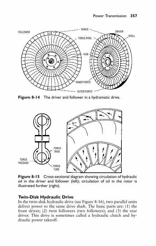
P1: JYC
GB098-08 GB098-Miller September 13, 2004 19:31 Char Count= 0
Power Transmission 357
FOLLOWERVANES
TORUS RING
DRIVERSHELL
HUB
OUTER PORTS
INNER PORTS
Figure 8-14 The driver and follower in a hydramatic drive.
TORUSPASSAGE
TORUSRING
TORUSTUBE
Figure 8-15 Cross-sectional diagram showing circulation of hydraulicoil in the driver and follower (left); circulation of oil in the rotor isillustrated further (right).
Twin-Disk Hydraulic DriveIn the twin-disk hydraulic drive (see Figure 8-16), two parallel unitsdeliver power to the same drive shaft. The basic parts are: (1) thefront driver; (2) twin followers (two followers); and (3) the reardriver. This drive is sometimes called a hydraulic clutch and hy-draulic power takeoff.
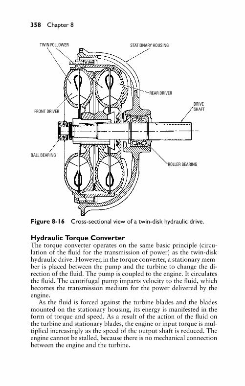
P1: JYC
GB098-08 GB098-Miller September 13, 2004 19:31 Char Count= 0
358 Chapter 8
TWIN FOLLOWER STATIONARY HOUSING
REAR DRIVER
DRIVESHAFT
ROLLER BEARING
BALL BEARING
FRONT DRIVER
Figure 8-16 Cross-sectional view of a twin-disk hydraulic drive.
Hydraulic Torque ConverterThe torque converter operates on the same basic principle (circu-lation of the fluid for the transmission of power) as the twin-diskhydraulic drive. However, in the torque converter, a stationary mem-ber is placed between the pump and the turbine to change the di-rection of the fluid. The pump is coupled to the engine. It circulatesthe fluid. The centrifugal pump imparts velocity to the fluid, whichbecomes the transmission medium for the power delivered by theengine.
As the fluid is forced against the turbine blades and the bladesmounted on the stationary housing, its energy is manifested in theform of torque and speed. As a result of the action of the fluid onthe turbine and stationary blades, the engine or input torque is mul-tiplied increasingly as the speed of the output shaft is reduced. Theengine cannot be stalled, because there is no mechanical connectionbetween the engine and the turbine.
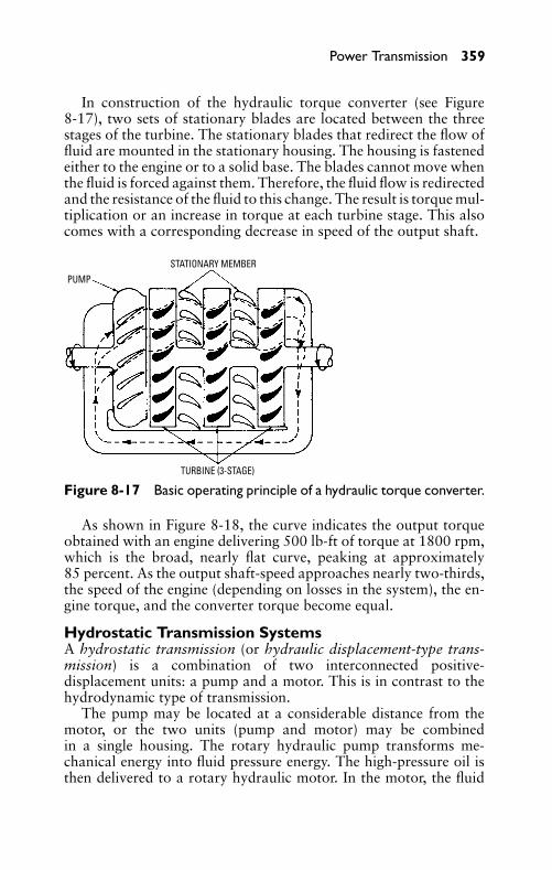
P1: JYC
GB098-08 GB098-Miller September 13, 2004 19:31 Char Count= 0
Power Transmission 359
In construction of the hydraulic torque converter (see Figure8-17), two sets of stationary blades are located between the threestages of the turbine. The stationary blades that redirect the flow offluid are mounted in the stationary housing. The housing is fastenedeither to the engine or to a solid base. The blades cannot move whenthe fluid is forced against them. Therefore, the fluid flow is redirectedand the resistance of the fluid to this change. The result is torque mul-tiplication or an increase in torque at each turbine stage. This alsocomes with a corresponding decrease in speed of the output shaft.
STATIONARY MEMBERPUMP
TURBINE (3-STAGE)
Figure 8-17 Basic operating principle of a hydraulic torque converter.
As shown in Figure 8-18, the curve indicates the output torqueobtained with an engine delivering 500 lb-ft of torque at 1800 rpm,which is the broad, nearly flat curve, peaking at approximately85 percent. As the output shaft-speed approaches nearly two-thirds,the speed of the engine (depending on losses in the system), the en-gine torque, and the converter torque become equal.
Hydrostatic Transmission SystemsA hydrostatic transmission (or hydraulic displacement-type trans-mission) is a combination of two interconnected positive-displacement units: a pump and a motor. This is in contrast to thehydrodynamic type of transmission.
The pump may be located at a considerable distance from themotor, or the two units (pump and motor) may be combinedin a single housing. The rotary hydraulic pump transforms me-chanical energy into fluid pressure energy. The high-pressure oil isthen delivered to a rotary hydraulic motor. In the motor, the fluid
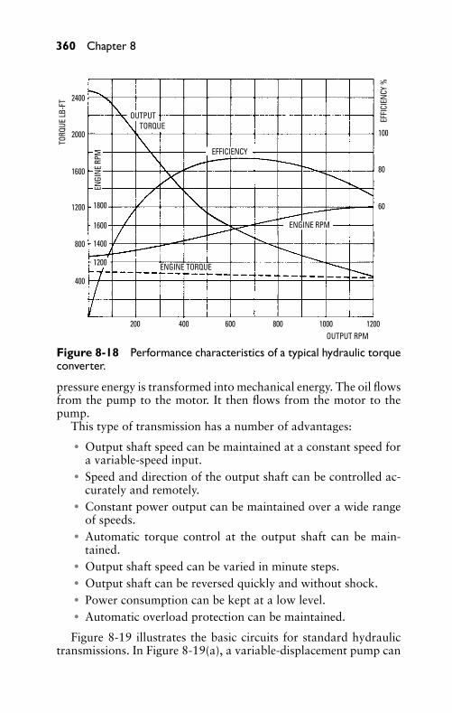
P1: JYC
GB098-08 GB098-Miller September 13, 2004 19:31 Char Count= 0
360 Chapter 8
OUTPUTTORQUE
EFFICIENCY
EFFI
CIEN
CY %
TORQ
UE LB
-FT
ENGINE RPM
OUTPUT RPM
ENGI
NE R
PM
ENGINE TORQUE
2400
2000
1600
1200
1200
1400
1600
1800
800
400
200 400 600 800 1000 1200
100
80
60
Figure 8-18 Performance characteristics of a typical hydraulic torqueconverter.
pressure energy is transformed into mechanical energy. The oil flowsfrom the pump to the motor. It then flows from the motor to thepump.
This type of transmission has a number of advantages:� Output shaft speed can be maintained at a constant speed for
a variable-speed input.� Speed and direction of the output shaft can be controlled ac-
curately and remotely.� Constant power output can be maintained over a wide range
of speeds.� Automatic torque control at the output shaft can be main-
tained.� Output shaft speed can be varied in minute steps.� Output shaft can be reversed quickly and without shock.� Power consumption can be kept at a low level.� Automatic overload protection can be maintained.
Figure 8-19 illustrates the basic circuits for standard hydraulictransmissions. In Figure 8-19(a), a variable-displacement pump can
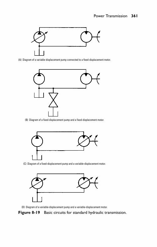
P1: JYC
GB098-08 GB098-Miller September 13, 2004 19:31 Char Count= 0
Power Transmission 361
(A) Diagram of a variable-displacement pump connected to a fixed-displacement motor.
(B) Diagram of a fixed-displacement pump and a fixed-displacement motor.
(C) Diagram of a fixed-displacement pump and a variable-displacement motor.
(D) Diagram of a variable-displacement pump and a variable-displacement motor.
Figure 8-19 Basic circuits for standard hydraulic transmission.
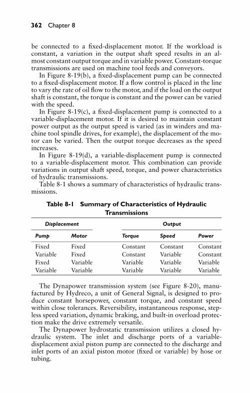
P1: JYC
GB098-08 GB098-Miller September 13, 2004 19:31 Char Count= 0
362 Chapter 8
be connected to a fixed-displacement motor. If the workload isconstant, a variation in the output shaft speed results in an al-most constant output torque and in variable power. Constant-torquetransmissions are used on machine tool feeds and conveyors.
In Figure 8-19(b), a fixed-displacement pump can be connectedto a fixed-displacement motor. If a flow control is placed in the lineto vary the rate of oil flow to the motor, and if the load on the outputshaft is constant, the torque is constant and the power can be variedwith the speed.
In Figure 8-19(c), a fixed-displacement pump is connected to avariable-displacement motor. If it is desired to maintain constantpower output as the output speed is varied (as in winders and ma-chine tool spindle drives, for example), the displacement of the mo-tor can be varied. Then the output torque decreases as the speedincreases.
In Figure 8-19(d), a variable-displacement pump is connectedto a variable-displacement motor. This combination can providevariations in output shaft speed, torque, and power characteristicsof hydraulic transmissions.
Table 8-1 shows a summary of characteristics of hydraulic trans-missions.
Table 8-1 Summary of Characteristics of HydraulicTransmissions
Displacement Output
Pump Motor Torque Speed Power
Fixed Fixed Constant Constant ConstantVariable Fixed Constant Variable ConstantFixed Variable Variable Variable VariableVariable Variable Variable Variable Variable
The Dynapower transmission system (see Figure 8-20), manu-factured by Hydreco, a unit of General Signal, is designed to pro-duce constant horsepower, constant torque, and constant speedwithin close tolerances. Reversibility, instantaneous response, step-less speed variation, dynamic braking, and built-in overload protec-tion make the drive extremely versatile.
The Dynapower hydrostatic transmission utilizes a closed hy-draulic system. The inlet and discharge ports of a variable-displacement axial piston pump are connected to the discharge andinlet ports of an axial piston motor (fixed or variable) by hose ortubing.
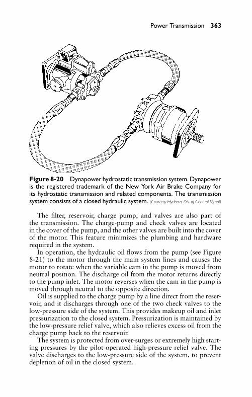
P1: JYC
GB098-08 GB098-Miller September 13, 2004 19:31 Char Count= 0
Power Transmission 363
Figure 8-20 Dynapower hydrostatic transmission system. Dynapoweris the registered trademark of the New York Air Brake Company forits hydrostatic transmission and related components. The transmissionsystem consists of a closed hydraulic system. (Courtesy Hydreco, Div. of General Signal)
The filter, reservoir, charge pump, and valves are also part ofthe transmission. The charge-pump and check valves are locatedin the cover of the pump, and the other valves are built into the coverof the motor. This feature minimizes the plumbing and hardwarerequired in the system.
In operation, the hydraulic oil flows from the pump (see Figure8-21) to the motor through the main system lines and causes themotor to rotate when the variable cam in the pump is moved fromneutral position. The discharge oil from the motor returns directlyto the pump inlet. The motor reverses when the cam in the pump ismoved through neutral to the opposite direction.
Oil is supplied to the charge pump by a line direct from the reser-voir, and it discharges through one of the two check valves to thelow-pressure side of the system. This provides makeup oil and inletpressurization to the closed system. Pressurization is maintained bythe low-pressure relief valve, which also relieves excess oil from thecharge pump back to the reservoir.
The system is protected from over-surges or extremely high start-ing pressures by the pilot-operated high-pressure relief valve. Thevalve discharges to the low-pressure side of the system, to preventdepletion of oil in the closed system.
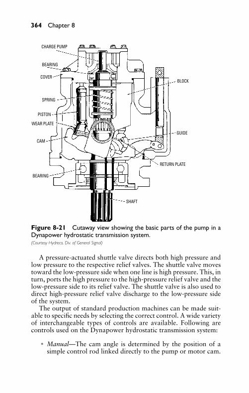
P1: JYC
GB098-08 GB098-Miller September 13, 2004 19:31 Char Count= 0
364 Chapter 8
CHARGE PUMP
BEARING
COVER
SPRING
PISTON
WEAR PLATE
CAM
BEARING
SHAFT
RETURN PLATE
GUIDE
BLOCK
Figure 8-21 Cutaway view showing the basic parts of the pump in aDynapower hydrostatic transmission system.(Courtesy Hydreco, Div. of General Signal)
A pressure-actuated shuttle valve directs both high pressure andlow pressure to the respective relief valves. The shuttle valve movestoward the low-pressure side when one line is high pressure. This, inturn, ports the high pressure to the high-pressure relief valve and thelow-pressure side to its relief valve. The shuttle valve is also used todirect high-pressure relief valve discharge to the low-pressure sideof the system.
The output of standard production machines can be made suit-able to specific needs by selecting the correct control. A wide varietyof interchangeable types of controls are available. Following arecontrols used on the Dynapower hydrostatic transmission system:
� Manual—The cam angle is determined by the position of asimple control rod linked directly to the pump or motor cam.
P1: JYC
GB098-08 GB098-Miller September 13, 2004 19:31 Char Count= 0
Power Transmission 365
A hand wheel on a threaded rod is attached for fine positioningof the pump or motor cam.
� Low-pressure hydraulic control—Charge pump pressure (ap-proximately 100 psi) is utilized by the control to positionthe cam and to provide over-center travel. The actuatingarm of the control requires 2 to 4 pounds of effort for itsoperation.
� Input torque limiting control—Stalling of the engine is pre-vented under all conditions.
� Constant-speed control—Input speeds can be varied whilemaintaining constant output speed. The output varies withdemand.
� Pressure-compensated motor control—Motor speed is in-creased automatically by decreasing the cam angle in the mo-tor, as pressure decreases. Conversely, by increasing the camangle in the motor as the pressure increases, lower speed andhigher output torque are obtained.
� Pressure-compensator pump control—This control has beenmade necessary by the hydrostatic transmission, although itis not normally a component of the system itself. Full flow(maximum cam angle) is maintained until a predeterminedsystem pressure is attained. The flow is then halted while thepressure is maintained. Flow resumes to compensate for systemleakage (or at system demand). A manual cutoff of flow andpressure can be used to reduce wear and horsepower demandon the system.
The transmission as shown in Figure 8-22 is designed to op-erate at speeds up to 4200 rpm and pressures up to 4500 psi.This transmission provides a smooth, infinite control of speed,direction, and dynamic braking with the touch of a single levercontrol. Use of this type of transmission is found on gardentractors, snowmobiles and other pleasure vehicles, materials-handling equipment, and on other applications requiring variablespeed.
Hydrostatic hydraulic drives have been developed for many mo-bile and industrial applications (see Figure 8-23). These drives areused on machine tools, centrifugal pumps, production machines,winches, paper and textile rolls, surface and center windows, con-veyors, reels, calendaring equipment, printing presses, fans andblowers, agitators, mixers, disintegrators, materials-handling ma-chines, plastic extruders, and dynamometers.
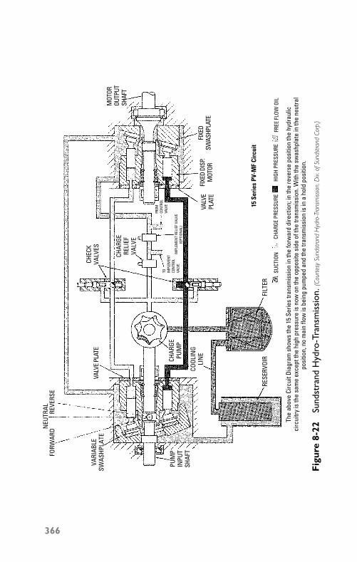
P1: JYC
GB098-08 GB098-Miller September 13, 2004 19:31 Char Count= 0
NEU
TRAL
FORW
ARD
REVE
RSE
VARI
ABLE
SWAS
HPLA
TE
PUM
PIN
PUT
SHAF
T
CHAR
GEPU
MP
COOL
ING
LIN
E
FILT
ER
CHAR
GE P
RESS
URE
HIGH
PRE
SSUR
EFR
EE F
LOW
OIL
VALV
EPL
ATE
VALV
E PL
ATE
FIXE
D DI
SP.
MOT
ORFI
XED
SWAS
HPLA
TE
FROM
CON
TROL
VALV
ETO IM
PLEM
ENT
CON
TROL
VALV
EIM
PLEM
ENT
RELI
EF V
ALVE
(OPT
ION
AL)
CHAR
GERE
LIEF
VALV
E
CHEC
KVA
LVES
The
abov
e Ci
rcui
t Dia
gram
sho
ws
the
15 S
erie
s tra
nsm
issi
on in
the
forw
ard
dire
ctio
n; in
the
reve
rse
posi
tion
the
hydr
aulic
circ
uitry
is th
e sa
me
exce
pt th
e hi
gh p
ress
ure
is n
ow o
n th
e op
posi
te s
ide
of th
e tra
nsm
issi
on. W
ith th
e sw
ashp
late
in th
e ne
utra
lpo
sitio
n, n
o m
ain
flow
is b
eing
pum
ped
and
the
trans
mis
sion
is in
a h
old
posi
tion.
MOT
OROU
TPUT
SHAF
T
15 S
erie
s PV
-MF
Circ
uit
SUCT
ION
RESE
RVOI
R
Fig
ure
8-22
Sund
stra
ndH
ydro
-Tra
nsm
issi
on. (
Cour
tesy
Sund
stra
ndH
ydro
-Tra
nsm
issio
n,D
iv.of
Sund
str a
ndCo
rp.)
366
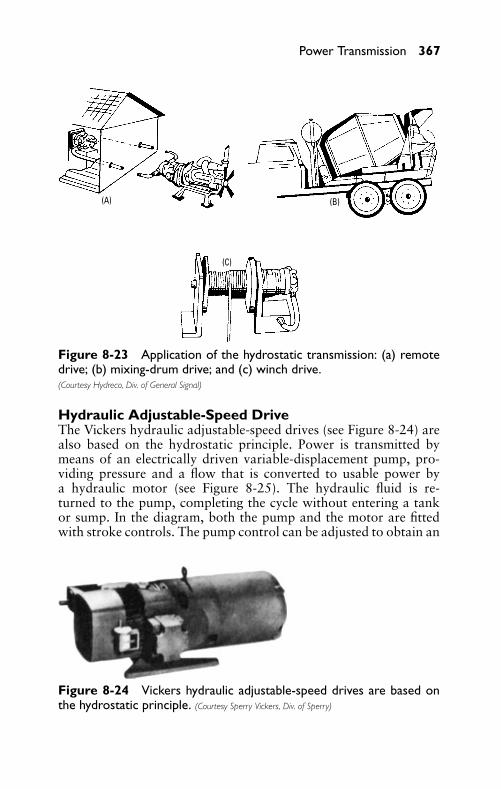
P1: JYC
GB098-08 GB098-Miller September 13, 2004 19:31 Char Count= 0
Power Transmission 367
(A)
(C)
(B)
Figure 8-23 Application of the hydrostatic transmission: (a) remotedrive; (b) mixing-drum drive; and (c) winch drive.(Courtesy Hydreco, Div. of General Signal)
Hydraulic Adjustable-Speed DriveThe Vickers hydraulic adjustable-speed drives (see Figure 8-24) arealso based on the hydrostatic principle. Power is transmitted bymeans of an electrically driven variable-displacement pump, pro-viding pressure and a flow that is converted to usable power bya hydraulic motor (see Figure 8-25). The hydraulic fluid is re-turned to the pump, completing the cycle without entering a tankor sump. In the diagram, both the pump and the motor are fittedwith stroke controls. The pump control can be adjusted to obtain an
Figure 8-24 Vickers hydraulic adjustable-speed drives are based onthe hydrostatic principle. (Courtesy Sperry Vickers, Div. of Sperry)
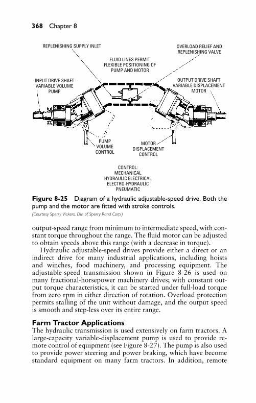
P1: JYC
GB098-08 GB098-Miller September 13, 2004 19:31 Char Count= 0
368 Chapter 8
REPLENISHING SUPPLY INLET
FLUID LINES PERMITFLEXIBLE POSITIONING OF
PUMP AND MOTOR
OVERLOAD RELIEF ANDREPLENISHING VALVE
INPUT DRIVE SHAFTVARIABLE VOLUME
PUMP
PUMPVOLUMECONTROL
CONTROL:MECHANICAL
HYDRAULIC ELECTRICALELECTRO-HYDRAULIC
PNEUMATIC
MOTORDISPLACEMENT
CONTROL
OUTPUT DRIVE SHAFTVARIABLE DISPLACEMENT
MOTOR
Figure 8-25 Diagram of a hydraulic adjustable-speed drive. Both thepump and the motor are fitted with stroke controls.(Courtesy Sperry Vickers, Div. of Sperry Rand Corp.)
output-speed range from minimum to intermediate speed, with con-stant torque throughout the range. The fluid motor can be adjustedto obtain speeds above this range (with a decrease in torque).
Hydraulic adjustable-speed drives provide either a direct or anindirect drive for many industrial applications, including hoistsand winches, food machinery, and processing equipment. Theadjustable-speed transmission shown in Figure 8-26 is used onmany fractional-horsepower machinery drives; with constant out-put torque characteristics, it can be started under full-load torquefrom zero rpm in either direction of rotation. Overload protectionpermits stalling of the unit without damage, and the output speedis smooth and step-less over its entire range.
Farm Tractor ApplicationsThe hydraulic transmission is used extensively on farm tractors. Alarge-capacity variable-displacement pump is used to provide re-mote control of equipment (see Figure 8-27). The pump is also usedto provide power steering and power braking, which have becomestandard equipment on many farm tractors. In addition, remote
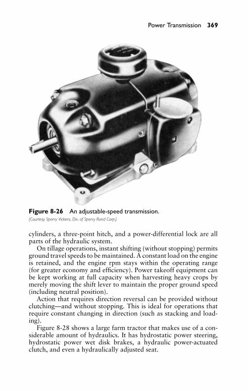
P1: JYC
GB098-08 GB098-Miller September 13, 2004 19:31 Char Count= 0
Power Transmission 369
Figure 8-26 An adjustable-speed transmission.(Courtesy Sperry Vickers, Div. of Sperry Rand Corp.)
cylinders, a three-point hitch, and a power-differential lock are allparts of the hydraulic system.
On tillage operations, instant shifting (without stopping) permitsground travel speeds to be maintained. A constant load on the engineis retained, and the engine rpm stays within the operating range(for greater economy and efficiency). Power takeoff equipment canbe kept working at full capacity when harvesting heavy crops bymerely moving the shift lever to maintain the proper ground speed(including neutral position).
Action that requires direction reversal can be provided withoutclutching—and without stopping. This is ideal for operations thatrequire constant changing in direction (such as stacking and load-ing).
Figure 8-28 shows a large farm tractor that makes use of a con-siderable amount of hydraulics. It has hydrostatic power steering,hydrostatic power wet disk brakes, a hydraulic power-actuatedclutch, and even a hydraulically adjusted seat.
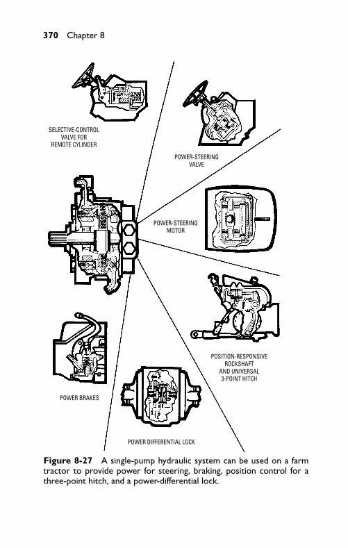
P1: JYC
GB098-08 GB098-Miller September 13, 2004 19:31 Char Count= 0
370 Chapter 8
SELECTIVE-CONTROLVALVE FOR
REMOTE CYLINDER
POWER-STEERINGVALVE
POWER-STEERINGMOTOR
POSITION-RESPONSIVEROCKSHAFT
AND UNIVERSAL3-POINT HITCH
POWER DIFFERENTIAL LOCK
POWER BRAKES
Figure 8-27 A single-pump hydraulic system can be used on a farmtractor to provide power for steering, braking, position control for athree-point hitch, and a power-differential lock.
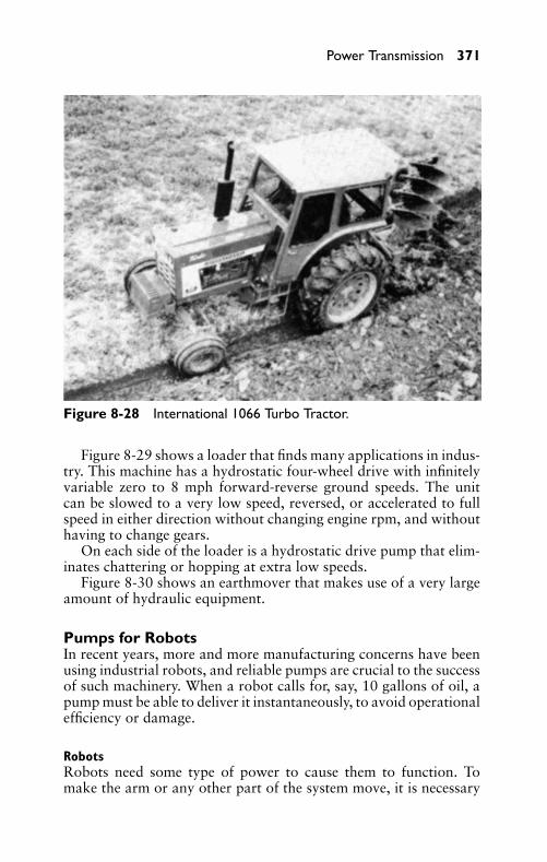
P1: JYC
GB098-08 GB098-Miller September 13, 2004 19:31 Char Count= 0
Power Transmission 371
Figure 8-28 International 1066 Turbo Tractor.
Figure 8-29 shows a loader that finds many applications in indus-try. This machine has a hydrostatic four-wheel drive with infinitelyvariable zero to 8 mph forward-reverse ground speeds. The unitcan be slowed to a very low speed, reversed, or accelerated to fullspeed in either direction without changing engine rpm, and withouthaving to change gears.
On each side of the loader is a hydrostatic drive pump that elim-inates chattering or hopping at extra low speeds.
Figure 8-30 shows an earthmover that makes use of a very largeamount of hydraulic equipment.
Pumps for RobotsIn recent years, more and more manufacturing concerns have beenusing industrial robots, and reliable pumps are crucial to the successof such machinery. When a robot calls for, say, 10 gallons of oil, apump must be able to deliver it instantaneously, to avoid operationalefficiency or damage.
RobotsRobots need some type of power to cause them to function. Tomake the arm or any other part of the system move, it is necessary
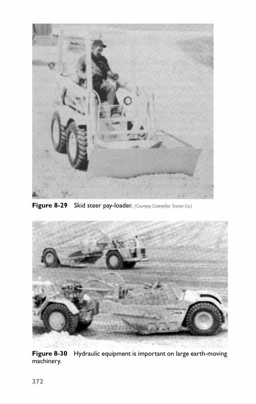
P1: JYC
GB098-08 GB098-Miller September 13, 2004 19:31 Char Count= 0
Figure 8-29 Skid steer pay-loader. (Courtesy Caterpillar Tractor Co.)
Figure 8-30 Hydraulic equipment is important on large earth-movingmachinery.
372
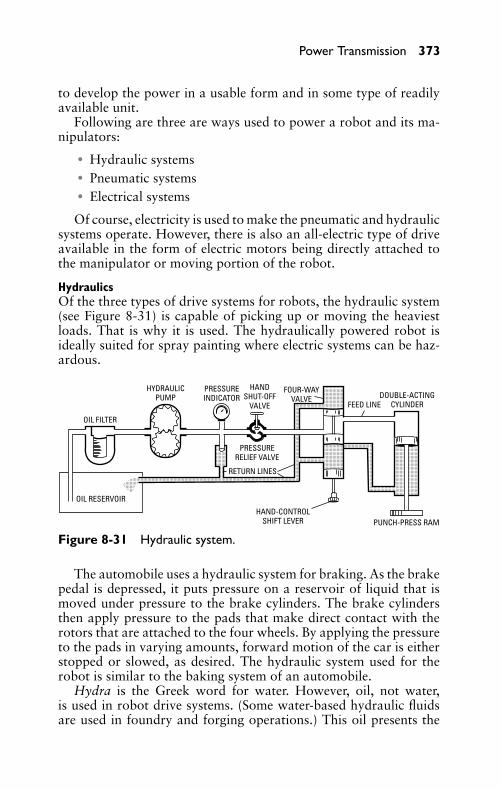
P1: JYC
GB098-08 GB098-Miller September 13, 2004 19:31 Char Count= 0
Power Transmission 373
to develop the power in a usable form and in some type of readilyavailable unit.
Following are three are ways used to power a robot and its ma-nipulators:
� Hydraulic systems� Pneumatic systems� Electrical systems
Of course, electricity is used to make the pneumatic and hydraulicsystems operate. However, there is also an all-electric type of driveavailable in the form of electric motors being directly attached tothe manipulator or moving portion of the robot.
HydraulicsOf the three types of drive systems for robots, the hydraulic system(see Figure 8-31) is capable of picking up or moving the heaviestloads. That is why it is used. The hydraulically powered robot isideally suited for spray painting where electric systems can be haz-ardous.
OIL FILTER
OIL RESERVOIR
HYDRAULICPUMP
PRESSUREINDICATOR
HANDSHUT-OFF
VALVE
FOUR-WAYVALVE
PUNCH-PRESS RAMHAND-CONTROL
SHIFT LEVER
RETURN LINES
PRESSURERELIEF VALVE
FEED LINEDOUBLE-ACTING
CYLINDER
Figure 8-31 Hydraulic system.
The automobile uses a hydraulic system for braking. As the brakepedal is depressed, it puts pressure on a reservoir of liquid that ismoved under pressure to the brake cylinders. The brake cylindersthen apply pressure to the pads that make direct contact with therotors that are attached to the four wheels. By applying the pressureto the pads in varying amounts, forward motion of the car is eitherstopped or slowed, as desired. The hydraulic system used for therobot is similar to the baking system of an automobile.
Hydra is the Greek word for water. However, oil, not water,is used in robot drive systems. (Some water-based hydraulic fluidsare used in foundry and forging operations.) This oil presents the
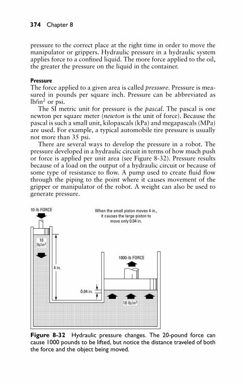
P1: JYC
GB098-08 GB098-Miller September 13, 2004 19:31 Char Count= 0
374 Chapter 8
pressure to the correct place at the right time in order to move themanipulator or grippers. Hydraulic pressure in a hydraulic systemapplies force to a confined liquid. The more force applied to the oil,the greater the pressure on the liquid in the container.
PressureThe force applied to a given area is called pressure. Pressure is mea-sured in pounds per square inch. Pressure can be abbreviated aslb/in2 or psi.
The SI metric unit for pressure is the pascal. The pascal is onenewton per square meter (newton is the unit of force). Because thepascal is such a small unit, kilopascals (kPa) and megapascals (MPa)are used. For example, a typical automobile tire pressure is usuallynot more than 35 psi.
There are several ways to develop the pressure in a robot. Thepressure developed in a hydraulic circuit in terms of how much pushor force is applied per unit area (see Figure 8-32). Pressure resultsbecause of a load on the output of a hydraulic circuit or because ofsome type of resistance to flow. A pump used to create fluid flowthrough the piping to the point where it causes movement of thegripper or manipulator of the robot. A weight can also be used togenerate pressure.
When the small piston moves 4 in.,it causes the large piston to
move only 0.04 in.
1000-lb FORCE
10-lb FORCE
10lb/in2
10 lb/in2
4 in.
0.04 in.
Figure 8-32 Hydraulic pressure changes. The 20-pound force cancause 1000 pounds to be lifted, but notice the distance traveled of boththe force and the object being moved.
P1: JYC
GB098-08 GB098-Miller September 13, 2004 19:31 Char Count= 0
Power Transmission 375
One of the disadvantages of using the hydraulic system is itsinherent problem with leaks. While fluid is under pressure, it has atendency to seek the weakest point in the system and then run out.This means that each joint along the piping must be able to withstandhigh pressure without leaking. It also means that the moving part ofthe robot (the manipulator) must be able to contain the fluid while itis under pressure. In most cases, the O-rings are not able to containthe fluid and leaks occur. O-rings are very important in sealing themoving end of the manipulator or terminating end of the fluid line.This is one of the maintenance problems associated with robotsused for picking up heavy objects. The hydraulics system is usedto pick up the weight. It is then typically dependent on industrialair pressure lines equal to at least 700 kPa. One lb/in2 is equal to6.896 kPa, and 1 kPa is equal to 1.45 lb/in2.
The pressure applied to a hydraulic system is in terms of howmuch push or force is applied to a container of oil, as shown inFigure 8-32. There are several ways to develop the pressure neededin a robot.
The pressure developed in a hydraulic circuit is in terms of howmuch push or force is applied per unit area. Pressure results becauseof a load on the output of a hydraulic circuit or because of sometype of resistance to flow.
A pump is used to create fluid flow thorough the piping to thepoint where it causes movement of the gripper or manipulator ofthe robot. A weight can also be used to generate pressure.
Pressure build-up in a hydraulic system can be a problem. It issometimes necessary to prevent its continuing to increase beyondthe capacity of the pipes and containers. That is where a relief valvebecomes important. A relief valve is used as an outlet when thepressure in the system rises beyond the point where the system canhandle it safely. The valve is closed as long as the pressure is belowits design value. Once the pressure reaches the point of design forthe relief valve, it opens. Then the excess fluid must be returned tothe reservoir or tank. This means a relief valve and the return of thefluid to tank must be part of the system.
Hydraulic systems need filters to keep the fluid clean. Even smallcontaminants can cause wear quickly. The filter must take outcontaminants that measure only microns in size. The filters mustbe changed regularly to keep the fluid and system in operatingcondition.
Pressures of several thousand psi are not uncommon in the oper-ation of a robot. This means that a leak as small as a pinhole can bedangerous. If you put your hand near a leak, it is possible that thefluid being emitted though the hole would cut off your hand before
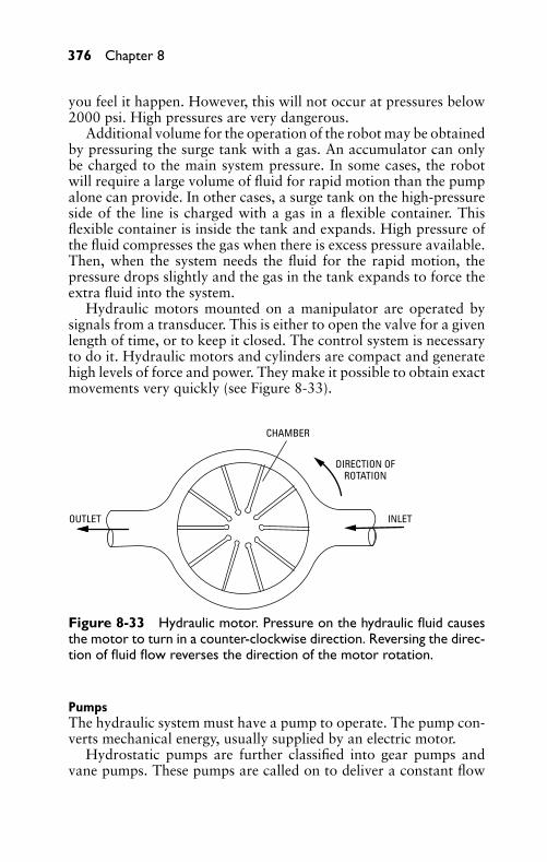
P1: JYC
GB098-08 GB098-Miller September 13, 2004 19:31 Char Count= 0
376 Chapter 8
you feel it happen. However, this will not occur at pressures below2000 psi. High pressures are very dangerous.
Additional volume for the operation of the robot may be obtainedby pressuring the surge tank with a gas. An accumulator can onlybe charged to the main system pressure. In some cases, the robotwill require a large volume of fluid for rapid motion than the pumpalone can provide. In other cases, a surge tank on the high-pressureside of the line is charged with a gas in a flexible container. Thisflexible container is inside the tank and expands. High pressure ofthe fluid compresses the gas when there is excess pressure available.Then, when the system needs the fluid for the rapid motion, thepressure drops slightly and the gas in the tank expands to force theextra fluid into the system.
Hydraulic motors mounted on a manipulator are operated bysignals from a transducer. This is either to open the valve for a givenlength of time, or to keep it closed. The control system is necessaryto do it. Hydraulic motors and cylinders are compact and generatehigh levels of force and power. They make it possible to obtain exactmovements very quickly (see Figure 8-33).
OUTLET INLET
DIRECTION OFROTATION
CHAMBER
Figure 8-33 Hydraulic motor. Pressure on the hydraulic fluid causesthe motor to turn in a counter-clockwise direction. Reversing the direc-tion of fluid flow reverses the direction of the motor rotation.
PumpsThe hydraulic system must have a pump to operate. The pump con-verts mechanical energy, usually supplied by an electric motor.
Hydrostatic pumps are further classified into gear pumps andvane pumps. These pumps are called on to deliver a constant flow
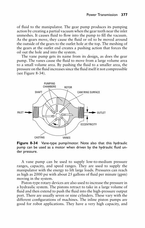
P1: JYC
GB098-08 GB098-Miller September 13, 2004 19:31 Char Count= 0
Power Transmission 377
of fluid to the manipulator. The gear pump produces its pumpingaction by creating a partial vacuum when the gear teeth near the inletunmeshes. It causes fluid to flow into the pump to fill the vacuum.As the gears move, they cause the fluid or oil to be moved aroundthe outside of the gears to the outlet hole at the top. The meshing ofthe gears at the outlet end creates a pushing action that forces theoil out the hole and into the system.
The vane pump gets its name from its design, as does the gearpump. The vanes cause the fluid to move from a large volume areato a small volume area. By pushing the fluid to a smaller area, thepressure on the fluid increases since the fluid itself it not compressible(see Figure 8-34).
INLET
CASTING VANES
SHAFT
PUMPINGCHAMBERS ROTOR
CAM RING SURFACE
OUTLET
ECCENTRICITY
Figure 8-34 Vane-type pump/motor. Note also that this hydraulicpump can be used as a motor when driven by the hydraulic fluid un-der pressure.
A vane pump can be used to supply low-to-medium pressureranges, capacity, and speed ranges. They are used to supply themanipulator with the energy to lift large loads. Pressures can reachas high as 2000 psi with about 25 gallons of fluid per minute (gpm)moving in the system.
Piston-type rotary devices are also used to increase the pressure ina hydraulic system. The pistons retract to take in a large volume offluid and then extend to push the fluid into the high-pressure outputport. There are usually seven or nine cylinders. These vary with thedifferent configurations of machines. The inline piston pumps aregood for robot applications. They have a very high capacity, and
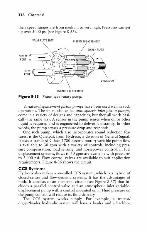
P1: JYC
GB098-08 GB098-Miller September 13, 2004 19:31 Char Count= 0
378 Chapter 8
their speed ranges are from medium to very high. Pressures can getup over 5000 psi (see Figure 8-35).
VALVE PLATE SLOT
OUTLETPORT
INLETPORT
CYLINDER BLOCK BORE
PISTON SUBASSEMBLY
SWASH PLATE
DRIVE SHAFT
Figure 8-35 Piston-type rotary pump.
Variable-displacement piston pumps have been used well in suchoperations. The units, also called atmospheric inlet piston pumps,come in a variety of designs and capacities, but they all work basi-cally the same way. A sensor in the pump senses when oil or otherliquid is required and is engineered to deliver it instantly. In otherwords, the pump senses a pressure drop and responds.
One such pump, which also incorporates sound reduction fea-tures, is the Quietpak from Hydreco, a division of General Signal.It uses a standard C-face 1780 electric motor; variable pump flowis available to 30 gpm with a variety of controls, including pres-sure compensation, load sensing, and horsepower control. In fueldisplacement systems, flows to 50 gpm are available with pressuresto 3,000 psi. Flow control valves are available to suit applicationrequirements. Figure 8-36 shows the circuit.
CCS SystemsHydreco also makes a so-called CCS system, which is a hybrid ofclosed-center and flow-demand systems. It has the advantages ofboth. It consists of an elemental circuit (see Figure 8-37) that in-cludes a parallel control valve and an atmospheric inlet variable-displacement pump with a control mounted on it. Fluid pressure onthe pump control will reduce its fluid delivery.
The CCS system works simply. For example, a tractor/digger/loader hydraulic system will have a loader and a backhoe
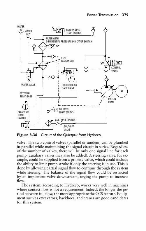
P1: JYC
GB098-08 GB098-Miller September 13, 2004 19:31 Char Count= 0
Power Transmission 379
WATERIN WATER
OUT
WATER VALVE
EXTERNALTEMP. GAGE
RETURN LINETEMP. SWITCH
FILTER WITHDIFFERENTIAL PRESSURE INDICATOR SWITCH
HEATEXCHANGER
PUSH TO READGAGE VALVE
OIL LEVELFLOAT SWITCH
SUCTION STRAINER
SHUT-OFFVALVE
RESERVOIRTEMP.SWITCH
PISTONPUMP
CONTROLVALVE
M
Figure 8-36 Circuit of the Quietpak from Hydreco.
valve. The two control valves (parallel or tandem) can be plumbedin parallel while maintaining the signal circuit in series. Regardlessof the number of valves, there will be only one signal line for eachpump (auxiliary valves may also be added). A steering valve, for ex-ample, could be supplied from a priority valve, which could includethe ability to limit pump stroke if only the steering is in use. This isdone by allowing partial signal flow to continue through the systemwhile steering. The balance of the signal flow could be restrictedby an implement valve downstream, urging the pump to increaseflow.
The system, according to Hydreco, works very well in machineswhere contact flow is not a requirement. Indeed, the longer the pe-riod between full flow, the more appropriate the CCS feature. Equip-ment such as excavators, backhoes, and cranes are good candidatesfor this system.
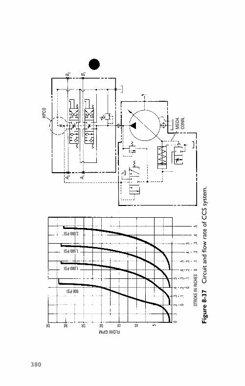
P1: JYC
GB098-08 GB098-Miller September 13, 2004 19:31 Char Count= 0
35 30 25 20 15 10 5
FLOW GPM
STRO
KE IN
INCH
ES
0.1
.2.3
.4.5
0.1
.2.3
.4.5
0.1
.2.3
.4.5
0.1
.2.3
.4.5
500 PSI
1,000 PSI
1,500 PSI
HPCO
B 2 B 1
A 2 A 1
MEC
H.CO
NN
.
2,000 PSI
Fig
ure
8-37
Cir
cuit
and
flow
rate
ofC
CS
syst
em.
380
P1: JYC
GB098-08 GB098-Miller September 13, 2004 19:31 Char Count= 0
Power Transmission 381
SummaryA hydraulic drive (also called fluid drive or liquid drive) is a flex-ible hydraulic coupling. It is a means of delivering power from aprime mover to a driven member through a liquid medium—withno mechanical connection.
The hydraulic drive mechanism consists of three essential parts:the driver,) follower, and casing (or housing). The power from theengine is delivered to the driver. It is then transmitted (flexibly) tothe follower through the hydraulic medium.
Centrifugal force acts on a body moving in a circular path, tend-ing to force it farther from its axis of rotation. For hydraulic oil tocirculate, it is necessary for the driver to rotate at a higher speed thanthe follower, because the intensity of the centrifugal force dependson the speed of rotation.
Both tangential acceleration and tangential deceleration requirean expenditure of energy (supplied by the engine). Most of the tan-gentially accelerated oil in the driver is converted at the follower intotorque during deceleration. Any expenditure of energy is required totangentially accelerate the oil, because the oil particles press againstthe vanes of the driver as they move outward.
The Dynapower hydrostatic transmission system is designed toproduce constant horsepower, constant torque, and constant speedwithin close tolerances. Reversibility, instantaneous response, step-less speed variation, dynamic braking, and built-in overload protec-tion make the drive extremely versatile.
Hydrostatic hydraulic drives have been developed for many mo-bile and industrial applications. These drives are used on machinetools, centrifugal pumps, production machines, winches, paper andtextile rolls, surface and center winders, conveyors, reels, calendar-ing equipment, printing presses, fans and blowers, agitators, mixers,disintegrators, materials-handling machines, plastic extruders, anddynamometers.
Hydraulic adjustable-speed drives are also based on the hydro-static principle. Either a direct or an indirect drive is provided formany applications (including hoists and winches, food machinery,and processing equipment).
The hydraulic transmission is also used extensively on farm trac-tors. The hydraulic system is used to provide remote control ofequipment, power steering, and power braking. Action that requiresdirection reversal can be provided without clutching—and withoutstopping. This is ideal for operations that require constant changingin direction (such as stacking and loading).
P1: JYC
GB098-08 GB098-Miller September 13, 2004 19:31 Char Count= 0
382 Chapter 8
Review Questions1. What is the basic operating principle of a hydraulic drive?2. What are the essential parts of a hydraulic drive mechanism?3. What conditions are necessary for hydraulic oil to circulate in
a hydraulic drive?4. Why is a torque a result of both tangential acceleration and
tangential deceleration of the hydraulic oil?5. List the advantages of a fluid drive.6. How does construction of the torque converter differ in con-
struction from the other hydraulic drives?7. List the advantages of the hydrostatic transmission.8. List six typical applications of the hydrostatic transmission.9. List the advantages of the hydraulic transmission for farm trac-
tor applications.10. What is another name for a hydraulic drive?11. What is dynamic inertia?12. What is kinetic energy?13. What are the two rotating elements in a fluid drive?14. What does declutching mean?15. What is a torque converter?16. What are the two interconnected positive displacement units
in a hydrostatic transmission?17. Draw the diagram for a fixed displacement pump and a vari-
able displacement motor.18. What type of transmission uses a closed hydraulic system?19. What type of transmission does the cement mixer-drum drive
utilize?20. Where are hydraulic adjustable-speed drives used?
P1: JYC
GB098-09 GB098-Miller September 13, 2004 18:2 Char Count= 0
Chapter 9Hydraulic Power ToolsHydraulic power transmission methods have contributed to the re-placement of pulleys and belts for electric motor drive units. In manyinstances, hydraulically controlled circuits and systems will operateand control machine tools and machinery in industry. The hydrauliccircuit includes a hydraulic pumping unit, necessary control valves,and the hydraulic actuator that consists of cylinder, motor, or rotaryactuator.
Figure. 9-1 shows a mobile aerial tower that uses a large amountof hydraulic equipment to accomplish its operation. An enginepower take-off drives a hydraulic pump that stores energy in anaccumulator. The system operating pressure is 1200 psi. The liftsare powered hydraulically by closed-center, parallel-circuit systems.The turntable [see Figure 9-1(a)] is actuated by a hydraulic motordrive.
Figure 9-2 shows a hydraulically operated load-unload mecha-nism as used in conjunction with a modern machine tool in a high-production plant.
Figure 9-3 illustrates a 28-ton hydraulic trim press. The operator’shands must remain on the cycle-start buttons to start and maintainthe cycle. If the operator removes one hand, the press ceases tooperate. If both hands are removed, not only will the cycle stop, butalso the shuttle will return to its start position. This is a desired safetyfeature on presses. Note how the cycle-start buttons have recessedheads to make them foolproof.
Hydraulic CircuitsThe hydraulic motor in a hydraulic circuit is operated by hydraulicoil under pressure. The function of the hydraulic motor is similar tothat of a prime mover (such as an electric motor or a steam engine).The hydraulic pump is used to supply hydraulic oil under pressureto the hydraulic motor. This is in the same manner that steam underpressure is piped to the steam engine. The hydraulic pump can bepositioned near the motor, combined with the motor in a single unit,or installed at a location remote from the motor.
Figure 9-4 shows a hydraulic power unit to which is mounted thehydraulic valve panel. This eliminates a lot of piping and presentsa neat, compact unit. Note that the electric motor and hydraulicpump are mounted in a vertical position.
383
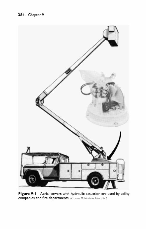
P1: JYC
GB098-09 GB098-Miller September 13, 2004 18:2 Char Count= 0
384 Chapter 9
Figure 9-1 Aerial towers with hydraulic actuation are used by utilitycompanies and fire departments. (Courtesy Mobile Aerial Towers, Inc.)
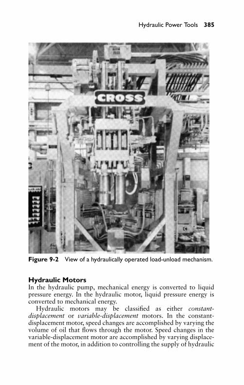
P1: JYC
GB098-09 GB098-Miller September 13, 2004 18:2 Char Count= 0
Hydraulic Power Tools 385
Figure 9-2 View of a hydraulically operated load-unload mechanism.
Hydraulic MotorsIn the hydraulic pump, mechanical energy is converted to liquidpressure energy. In the hydraulic motor, liquid pressure energy isconverted to mechanical energy.
Hydraulic motors may be classified as either constant-displacement or variable-displacement motors. In the constant-displacement motor, speed changes are accomplished by varying thevolume of oil that flows through the motor. Speed changes in thevariable-displacement motor are accomplished by varying displace-ment of the motor, in addition to controlling the supply of hydraulic
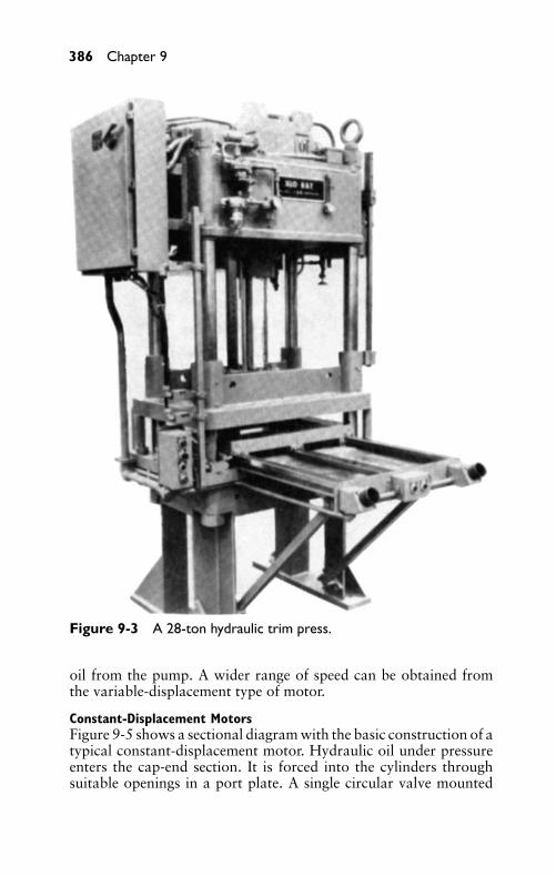
P1: JYC
GB098-09 GB098-Miller September 13, 2004 18:2 Char Count= 0
386 Chapter 9
Figure 9-3 A 28-ton hydraulic trim press.
oil from the pump. A wider range of speed can be obtained fromthe variable-displacement type of motor.
Constant-Displacement MotorsFigure 9-5 shows a sectional diagram with the basic construction of atypical constant-displacement motor. Hydraulic oil under pressureenters the cap-end section. It is forced into the cylinders throughsuitable openings in a port plate. A single circular valve mounted
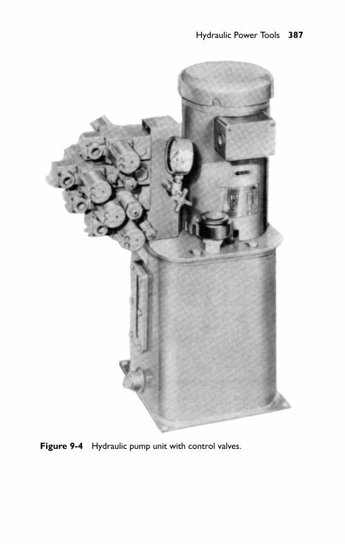
P1: JYC
GB098-09 GB098-Miller September 13, 2004 18:2 Char Count= 0
Hydraulic Power Tools 387
Figure 9-4 Hydraulic pump unit with control valves.

P1: JYC
GB098-09 GB098-Miller September 13, 2004 18:2 Char Count= 0
388 Chapter 9
Figure 9-5 Basic construction of a typical constant-displacement hy-draulic motor.
on an eccentric stud formed on the end of the shaft controls thepassage of oil through the ports. The valve does not rotate, but itdoes receive a gyrating motion as the shaft turns.
Hydraulic oil pressure forces the pistons (see Figure 9-6) againstthe non-rotating wobbler. The thrust of the pistons is both perpen-dicular and tangential, because the wobbler is inclined at an angle.The resultant force is transmitted through ball bearings to the wob-bler plate on the shaft, thereby imparting a rotating action to theplate. On the return stroke, the cylinders are emptied through thesame ports in the port plate.
Figure 9-6 Construction details of piston and connecting rod used ina hydraulic motor.
Variable-Displacement MotorsThe piston stroke can be varied in the variable-displacement typeof hydraulic motors by changing the angle at which the wobbleris inclined. The axial piston-type motor can be either a constant-displacement or a variable-displacement motor, depending on the
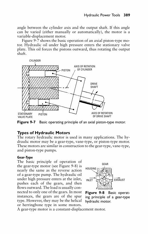
P1: JYC
GB098-09 GB098-Miller September 13, 2004 18:2 Char Count= 0
Hydraulic Power Tools 389
angle between the cylinder axis and the output shaft. If this anglecan be varied (either manually or automatically), the motor is avariable-displacement motor.
Figure 9-7 shows the basic operation of an axial piston-type mo-tor. Hydraulic oil under high pressure enters the stationary valveplate. This oil forces the pistons outward, thus rotating the outputshaft.
CYLINDER
PISTON
PISTON
DRIVESHAFT
STATIONARYVALVE PLATE
AXIS OF ROTATIONOF CYLINDER
AXIS OF ROTATIONOF DRIVE SHAFT
Figure 9-7 Basic operating principle of an axial piston-type motor.
Types of Hydraulic MotorsThe rotary hydraulic motor is used in many applications. The hy-draulic motor may be a gear-type, vane-type, or piston-type motor.These motors are similar in construction to the gear-type, vane-type,and piston-type pumps.
GEAR
HOUSING
INLET EXHAUST
Figure 9-8 Basic operat-ing principle of a gear-typehydraulic motor.
Gear-TypeThe basic principle of operation ofthe gear-type motor (see Figure 9-8) isnearly the same as the reverse actionof a gear-type pump. The hydraulic oilunder high pressure enters at the inlet,pushes each of the gears, and thenflows outward. The load is usually con-nected to only one of the gears. In mostinstances, the gears are of the spurtype. However, they may be the helicalor herringbone type in some motors.A gear-type motor is a constant-displacement motor.
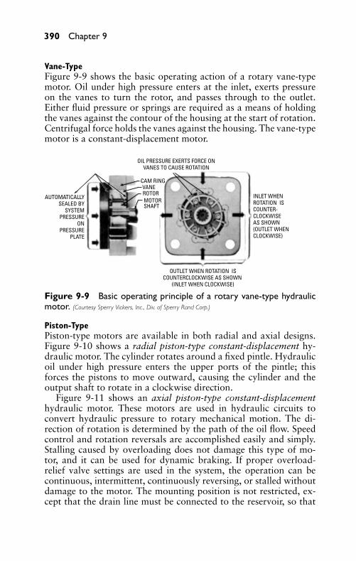
P1: JYC
GB098-09 GB098-Miller September 13, 2004 18:2 Char Count= 0
390 Chapter 9
Vane-TypeFigure 9-9 shows the basic operating action of a rotary vane-typemotor. Oil under high pressure enters at the inlet, exerts pressureon the vanes to turn the rotor, and passes through to the outlet.Either fluid pressure or springs are required as a means of holdingthe vanes against the contour of the housing at the start of rotation.Centrifugal force holds the vanes against the housing. The vane-typemotor is a constant-displacement motor.
AUTOMATICALLYSEALED BY
SYSTEMPRESSURE
ONPRESSURE
PLATE
OIL PRESSURE EXERTS FORCE ONVANES TO CAUSE ROTATION
CAM RINGVANEROTORMOTORSHAFT
INLET WHENROTATION ISCOUNTER-CLOCKWISEAS SHOWN (OUTLET WHENCLOCKWISE)
OUTLET WHEN ROTATION ISCOUNTERCLOCKWISE AS SHOWN
(INLET WHEN CLOCKWISE)
Figure 9-9 Basic operating principle of a rotary vane-type hydraulicmotor. (Courtesy Sperry Vickers, Inc., Div. of Sperry Rand Corp.)
Piston-TypePiston-type motors are available in both radial and axial designs.Figure 9-10 shows a radial piston-type constant-displacement hy-draulic motor. The cylinder rotates around a fixed pintle. Hydraulicoil under high pressure enters the upper ports of the pintle; thisforces the pistons to move outward, causing the cylinder and theoutput shaft to rotate in a clockwise direction.
Figure 9-11 shows an axial piston-type constant-displacementhydraulic motor. These motors are used in hydraulic circuits toconvert hydraulic pressure to rotary mechanical motion. The di-rection of rotation is determined by the path of the oil flow. Speedcontrol and rotation reversals are accomplished easily and simply.Stalling caused by overloading does not damage this type of mo-tor, and it can be used for dynamic braking. If proper overload-relief valve settings are used in the system, the operation can becontinuous, intermittent, continuously reversing, or stalled withoutdamage to the motor. The mounting position is not restricted, ex-cept that the drain line must be connected to the reservoir, so that
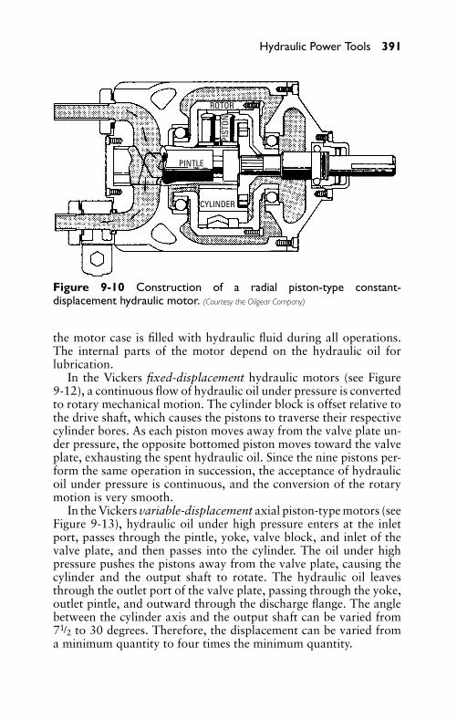
P1: JYC
GB098-09 GB098-Miller September 13, 2004 18:2 Char Count= 0
Hydraulic Power Tools 391
ROTOR
PINTLE
CYLINDER
PIST
ON
Figure 9-10 Construction of a radial piston-type constant-displacement hydraulic motor. (Courtesy the Oilgear Company)
the motor case is filled with hydraulic fluid during all operations.The internal parts of the motor depend on the hydraulic oil forlubrication.
In the Vickers fixed-displacement hydraulic motors (see Figure9-12), a continuous flow of hydraulic oil under pressure is convertedto rotary mechanical motion. The cylinder block is offset relative tothe drive shaft, which causes the pistons to traverse their respectivecylinder bores. As each piston moves away from the valve plate un-der pressure, the opposite bottomed piston moves toward the valveplate, exhausting the spent hydraulic oil. Since the nine pistons per-form the same operation in succession, the acceptance of hydraulicoil under pressure is continuous, and the conversion of the rotarymotion is very smooth.
In the Vickers variable-displacement axial piston-type motors (seeFigure 9-13), hydraulic oil under high pressure enters at the inletport, passes through the pintle, yoke, valve block, and inlet of thevalve plate, and then passes into the cylinder. The oil under highpressure pushes the pistons away from the valve plate, causing thecylinder and the output shaft to rotate. The hydraulic oil leavesthrough the outlet port of the valve plate, passing through the yoke,outlet pintle, and outward through the discharge flange. The anglebetween the cylinder axis and the output shaft can be varied from71/2 to 30 degrees. Therefore, the displacement can be varied froma minimum quantity to four times the minimum quantity.
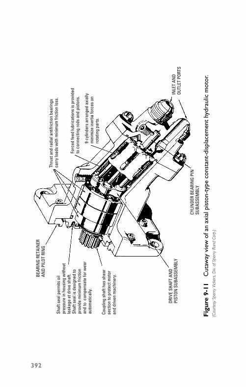
P1: JYC
GB098-09 GB098-Miller September 13, 2004 18:2 Char Count= 0
Thru
st a
nd ra
dial
ant
ifric
tion
bear
ings
carr
y lo
ads
with
min
imum
fric
tion
loss
.
Forc
ed fe
ed lu
bric
atio
ns is
pro
vide
dto
con
nect
ing
rods
and
pis
tons
.
9 cy
linde
rs a
rran
ged
axia
llym
inim
ize in
ertia
forc
es o
nro
tatin
g pa
rts.
INLE
T AN
DOU
TLET
POR
TS
CYLI
NDE
R BE
ARIN
G PI
NSU
BASS
EMBL
Y
DRIV
E SH
AFT
AND
PIST
ON S
UBAS
SEM
BLY
BEAR
ING
RETA
INER
AND
PILO
T RI
NG
Shaf
t sea
l per
mits
oil
pres
sure
in h
ousi
ng w
ithou
tle
akag
e at
driv
e sh
aft.
Shaf
t sea
l is
desi
gned
topr
ovid
e m
inim
um fr
ictio
nan
d to
com
pens
ate
for w
ear
auto
mat
ical
ly.
Coup
ling
shaf
t has
she
arse
ctio
n to
pro
tect
mot
oran
d dr
iven
mac
hine
ry.
Fig
ure
9-11
Cut
away
view
ofan
axia
lpis
ton-
type
cons
tant
-dis
plac
emen
thy
drau
licm
otor
.(C
ourt
esy
Sper
ryVi
cker
s,D
iv.of
Sper
ryRa
ndCo
rp.)
392
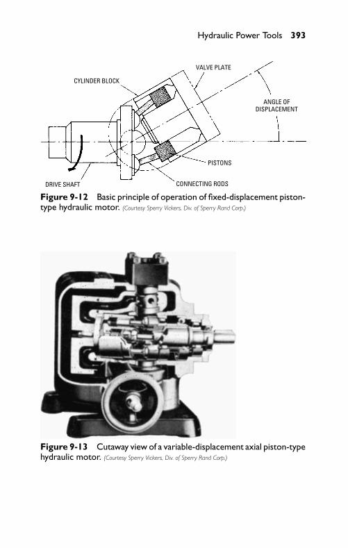
P1: JYC
GB098-09 GB098-Miller September 13, 2004 18:2 Char Count= 0
Hydraulic Power Tools 393
CYLINDER BLOCK
VALVE PLATE
ANGLE OFDISPLACEMENT
DRIVE SHAFT
PISTONS
CONNECTING RODS
Figure 9-12 Basic principle of operation of fixed-displacement piston-type hydraulic motor. (Courtesy Sperry Vickers, Div. of Sperry Rand Corp.)
Figure 9-13 Cutaway view of a variable-displacement axial piston-typehydraulic motor. (Courtesy Sperry Vickers, Div. of Sperry Rand Corp.)
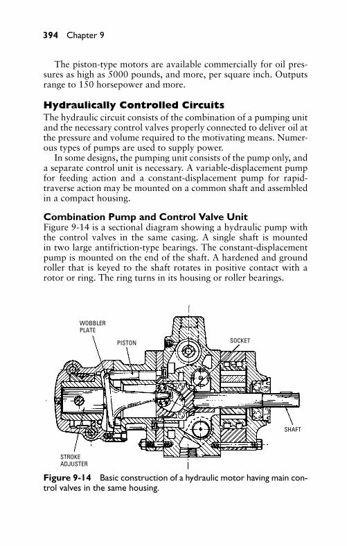
P1: JYC
GB098-09 GB098-Miller September 13, 2004 18:2 Char Count= 0
394 Chapter 9
The piston-type motors are available commercially for oil pres-sures as high as 5000 pounds, and more, per square inch. Outputsrange to 150 horsepower and more.
Hydraulically Controlled CircuitsThe hydraulic circuit consists of the combination of a pumping unitand the necessary control valves properly connected to deliver oil atthe pressure and volume required to the motivating means. Numer-ous types of pumps are used to supply power.
In some designs, the pumping unit consists of the pump only, anda separate control unit is necessary. A variable-displacement pumpfor feeding action and a constant-displacement pump for rapid-traverse action may be mounted on a common shaft and assembledin a compact housing.
Combination Pump and Control Valve UnitFigure 9-14 is a sectional diagram showing a hydraulic pump withthe control valves in the same casing. A single shaft is mountedin two large antifriction-type bearings. The constant-displacementpump is mounted on the end of the shaft. A hardened and groundroller that is keyed to the shaft rotates in positive contact with arotor or ring. The ring turns in its housing or roller bearings.
WOBBLERPLATE
PISTON SOCKET
SHAFT
STROKEADJUSTER
Figure 9-14 Basic construction of a hydraulic motor having main con-trol valves in the same housing.
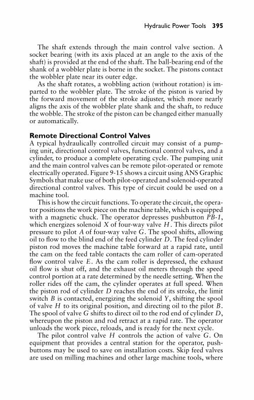
P1: JYC
GB098-09 GB098-Miller September 13, 2004 18:2 Char Count= 0
Hydraulic Power Tools 395
The shaft extends through the main control valve section. Asocket bearing (with its axis placed at an angle to the axis of theshaft) is provided at the end of the shaft. The ball-bearing end of theshank of a wobbler plate is borne in the socket. The pistons contactthe wobbler plate near its outer edge.
As the shaft rotates, a wobbling action (without rotation) is im-parted to the wobbler plate. The stroke of the piston is varied bythe forward movement of the stroke adjuster, which more nearlyaligns the axis of the wobbler plate shank and the shaft, to reducethe wobble. The stroke of the piston can be changed either manuallyor automatically.
Remote Directional Control ValvesA typical hydraulically controlled circuit may consist of a pump-ing unit, directional control valves, functional control valves, and acylinder, to produce a complete operating cycle. The pumping unitand the main control valves can be remote pilot-operated or remoteelectrically operated. Figure 9-15 shows a circuit using ANS GraphicSymbols that make use of both pilot-operated and solenoid-operateddirectional control valves. This type of circuit could be used on amachine tool.
This is how the circuit functions. To operate the circuit, the opera-tor positions the work piece on the machine table, which is equippedwith a magnetic chuck. The operator depresses pushbutton PB-1,which energizes solenoid X of four-way valve H . This directs pilotpressure to pilot A of four-way valve G. The spool shifts, allowingoil to flow to the blind end of the feed cylinder D. The feed cylinderpiston rod moves the machine table forward at a rapid rate, untilthe cam on the feed table contacts the cam roller of cam-operatedflow control valve E . As the cam roller is depressed, the exhaustoil flow is shut off, and the exhaust oil meters through the speedcontrol portion at a rate determined by the needle setting. When theroller rides off the cam, the cylinder operates at full speed. Whenthe piston rod of cylinder D reaches the end of its stroke, the limitswitch B is contacted, energizing the solenoid Y, shifting the spoolof valve H to its original position, and directing oil to the pilot B.The spool of valve G shifts to direct oil to the rod end of cylinder D,whereupon the piston and rod retract at a rapid rate. The operatorunloads the work piece, reloads, and is ready for the next cycle.
The pilot control valve H controls the action of valve G. Onequipment that provides a central station for the operator, push-buttons may be used to save on installation costs. Skip feed valvesare used on milling machines and other large machine tools, where
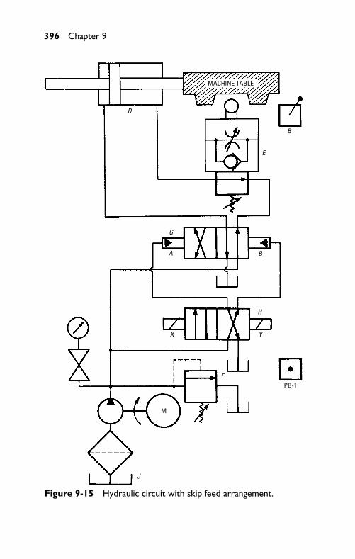
P1: JYC
GB098-09 GB098-Miller September 13, 2004 18:2 Char Count= 0
396 Chapter 9
MACHINE TABLE
D
E
B
BA
G
X
H
Y
F
J
M
PB-1
Figure 9-15 Hydraulic circuit with skip feed arrangement.
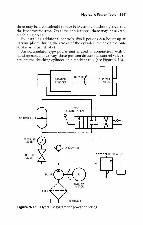
P1: JYC
GB098-09 GB098-Miller September 13, 2004 18:2 Char Count= 0
Hydraulic Power Tools 397
there may be a considerable space between the machining area andthe free traverse area. On some applications, there may be severalmachining areas.
By installing additional controls, dwell periods can be set up atvarious places during the stroke of the cylinder (either on the out-stroke or return stroke).
An accumulator-type power unit is used in conjunction with ahand-operated, four-way, three-position directional control valve toactuate the chucking cylinder on a machine tool (see Figure 9-16).
ROTATINGCYLINDER
DRAWRODPOWERCHUCK
4-WAYCONTROL VALVE
ACCUMULATOR
PRESSUREGAGE
SHUT-OFFVALVE
CHECK VALVE
PUMP
FILTER
RESERVOIR
ELECTRICMOTOR
RELIEF VALVE
M
Figure 9-16 Hydraulic system for power chucking.
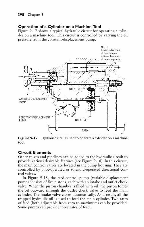
P1: JYC
GB098-09 GB098-Miller September 13, 2004 18:2 Char Count= 0
398 Chapter 9
Operation of a Cylinder on a Machine ToolFigure 9-17 shows a typical hydraulic circuit for operating a cylin-der on a machine tool. This circuit is controlled by varying the oilpressure from the constant-displacement pump.
NOTE:Reverse directionof flow to maincylinder by meansof reversing valve.
NO. 3 LINE
VARIABLE-DISPLACEMENTPUMP
CONSTANT-DISPLACEMENTPUMP NO. 2 LINE
TANK
Figure 9-17 Hydraulic circuit used to operate a cylinder on a machinetool.
Circuit ElementsOther valves and pipelines can be added to the hydraulic circuit toprovide various desirable features (see Figure 9-18). In this circuit,the main control valves are located in the pump housing. They arecontrolled by pilot-operated or solenoid-operated directional con-trol valves.
In Figure 9-18, the feed-control pump (variable-displacementpump) consists of five pistons, each with an intake and outlet checkvalve. When the piston chamber is filled with oil, the piston forcesthe oil outward through the outlet check valve to feed the maincylinder. The intake valve closes automatically. As a result, all thetrapped hydraulic oil is used to feed the main cylinder. Two ratesof feed (both adjustable from zero to maximum) can be provided.Some pumps can provide three rates of feed.
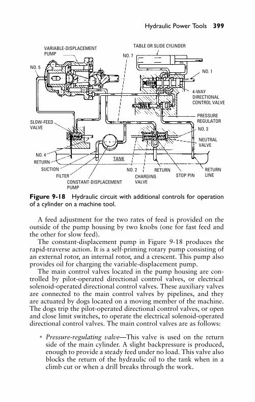
P1: JYC
GB098-09 GB098-Miller September 13, 2004 18:2 Char Count= 0
Hydraulic Power Tools 399
VARIABLE-DISPLACEMENTPUMP
NO. 5
SLOW-FEEDVALVE
NO. 4RETURN
SUCTIONFILTER
CONSTANT-DISPLACEMENTPUMP
TANK
NO. 2 CHARGINGVALVE
RETURNSTOP PIN
RETURNLINE
NEUTRALVALVE
NO. 3
PRESSUREREGULATOR
4-WAYDIRECTIONALCONTROL VALVE
NO. 1
TABLE OR SLIDE CYLINDER
NO. 7
Figure 9-18 Hydraulic circuit with additional controls for operationof a cylinder on a machine tool.
A feed adjustment for the two rates of feed is provided on theoutside of the pump housing by two knobs (one for fast feed andthe other for slow feed).
The constant-displacement pump in Figure 9-18 produces therapid-traverse action. It is a self-priming rotary pump consisting ofan external rotor, an internal rotor, and a crescent. This pump alsoprovides oil for charging the variable-displacement pump.
The main control valves located in the pump housing are con-trolled by pilot-operated directional control valves, or electricalsolenoid-operated directional control valves. These auxiliary valvesare connected to the main control valves by pipelines, and theyare actuated by dogs located on a moving member of the machine.The dogs trip the pilot-operated directional control valves, or openand close limit switches, to operate the electrical solenoid-operateddirectional control valves. The main control valves are as follows:
� Pressure-regulating valve—This valve is used on the returnside of the main cylinder. A slight backpressure is produced,enough to provide a steady feed under no load. This valve alsoblocks the return of the hydraulic oil to the tank when in aclimb cut or when a drill breaks through the work.
P1: JYC
GB098-09 GB098-Miller September 13, 2004 18:2 Char Count= 0
400 Chapter 9
The valve is opened by the working pressure, and is closed bya spring. The spring determines the minimum (but not maxi-mum) working pressure. Therefore, there is a fixed minimumworking pressure at all times. The spring also controls theopening required in the valve during a climb cut to keep thepiston in the main cylinder from traveling at a faster rate thanthe preset rate of the variable-displacement pump. The pumpis not required to build up pressure during a climb cut (as ona milling machine), because the milling cutter pulls the work,which forces the oil out of the main cylinder.
� Four-way directional control valve—The spring-return four-way directional control valve is positioned in the circuit be-tween the main cylinder and the pressure-regulating valve.The valve is positioned at one of the valve bores by meansof a spring, thereby creating forward cylinder movement bydirecting oil to an outlet port. Reversing movement occurswhen hydraulic oil pressure is exerted against the plunger endopposite the spring end, directing the oil to the other outletport.
� Neutral control valve—If this valve is open, the entire out-put of the constant-displacement pump returns to the tank.When the circuit is in “feed” and “rapid-traverse” positionsthe neutral control valve is closed and it remains closed. It staysclosed during the entire cycle. A small hole in the valve pumppermits oil to return to the tank through a pilot line to thepilot-operated valve. When the pilot-operated valve preventsthe escape of oil through this hole, the neutral control valvecloses.
� Charging-valve—When it is open, this valve creates the pres-sure required to charge the variable-displacement piston-typepump with oil from the constant-displacement pump, and per-mits the surplus oil to return to the tank at charging pressure.When the valve is closed, the entire output of the constant-displacement pump is forced through the check valves on thevariable-displacement pump to the actuated unit, producingthe rapid-traverse action. A small hole in the valve plungerpermits oil to return to the tank through a pilot line to the pi-lot valve. The pilot-operated directional control valve preventsthe escape of oil through the small hole to close the chargingvalve.
� Slow-feed valve—With this valve, two preset rates of feed canbe obtained. When the valve is open, a fast feed results. A
P1: JYC
GB098-09 GB098-Miller September 13, 2004 18:2 Char Count= 0
Hydraulic Power Tools 401
slower rate of feed is obtained when the valve is closed. Anintermediate feed can be obtained while the valve is open fora third rate of feed.
� Pressure-relief valve—When an actuated machine memberfeeds against a positive stop or during overload, this reliefvalve serves as a safety valve. A preset pressure setting is usedfor the valve.
The pipelines (see Figure 9-18) serve various purposes. Thepipeline from the pilot-operated directional control valve to the tankis not numbered in the illustration. It returns the excess oil to thetank.
A pipeline (see No. 1 in Figure 9-18) is connected to each endof the spring-return four-way directional control valve to controlthe position of the valve spool. Actuation of the pilot- or solenoid-operated directional control valve admits pressure to one of the lines,and opens, simultaneously, the other line to the tank. This movesthe four-way valve spool to the desired position.
In some four-way directional control valves, the spool is held inposition by a spring for forward travel. Then only pipeline No. 1 isnecessary. Oil pressure in pipeline No. 1 overcomes the resistanceof the spring and shifts the valve spool to “rapid-return” position.When line No. 1 is opened to the tank, the spring returns the valvespool to its former position.
The spring end of the charging valve chamber is connected withthe pilot-operated directional control valve by pipeline No. 2. Whenthe pilot-operated directional control valve closes the line, the valveplunger in the charging valve is seated. This is accomplished bypreventing passage of the oil through line No. 2 and returning tothe tank. When pipeline No. 2 is open, the charging valve is open andfeeding action occurs. Rapid-traverse action occurs when pipelineNo. 2 is closed and the charging valve is closed.
The spring end of the neutral control valve chamber is connectedto the pilot-operated directional control valve by pipeline No. 3.When the control valve closes the pipeline, the valve plunger in theneutral valve is seated. This is accomplished by preventing the escapeof oil to the control valve and back to the tank. When pipeline No.3 is closed, the neutral valve closes and either a feeding action ora rapid-traverse action occurs. When pipeline No. 3 is open, theneutral valve is open and the circuit is neutral.
Pipeline No. 4 connects the slow-feed valve to the charging valve,and pipeline No. 5 connects the chamber of the slow-feed controlvalve with the feed-adjusting housing.
P1: JYC
GB098-09 GB098-Miller September 13, 2004 18:2 Char Count= 0
402 Chapter 9
Pipeline No. 6 is used only in conjunction with solenoid-operateddirectional control valves for remote pushbutton starting and foremergency-return action. Charging pressure from the constant-displacement pump is conducted through pipeline No. 7 to the re-mote directional control valve that, in turn, distributes the pressureto accomplish various functions.
Operation of the Hydraulic CircuitIn the hydraulic circuit (see Figure 9-18), opening and closingof the neutral valve and the charging valve controls both theconstant-displacement pump and the variable-displacement pump.The constant-displacement pump (which is self-priming) pumps hy-draulic oil to a chamber that is open to the valve side of both theneutral valve and the charging valve.
In rapid-traverse action, all the oil from the constant-displacement pump is required, forcing it through the piston cham-bers in the variable-displacement pump and onward through themain cylinder. This is accomplished by actuating the pilot-operatedcontrol valve that closes pipelines No. 2 and No. 3, thereby clos-ing both the neutral valve and the charging valve. The direction ofrapid-traverse is determined by the position of the four-way direc-tional control valve spool. On some models, the four-way directionalcontrol valve is constructed in such a manner that pipeline No. 2 isblocked automatically, to eliminate a reverse feed, when the valvespool is in the reverse rapid-traverse position.
The feeding action (either fast or slow) is obtained by openingthe charging valve. This establishes sufficient pressure to keep thepistons in the variable-displacement pump against the wobbler plate,thereby charging the piston-type pump, which is not self-priming.The excess oil is returned to the tank through the charging valve. In“fast-feed” position, pipelines No. 2 and No. 4 are open to the tank,and pipeline No. 3 is closed. In “slow-feed” position, pipeline No. 2to the tank is open, pipeline No. 3 is closed, and pipeline No. 4is open to the charging pressure. The charging pressure shifts the“slow-feed” valve plunger to direct the pressure in pipeline No. 5to the wobbler support plunger in the variable-displacement pump,which forces the plunger forward to provide the slow rate of feedby decreasing the piston travel.
The third or intermediate rate of feed can be obtained by means ofa special feed-adjustment housing which contains an auxiliary wob-bler plunger, feed-adjusting screw, and feed-adjusting cam used inconjunction with a solenoid-operated directional control valve. Theadditional directional control valve is connected to a high-pressure
P1: JYC
GB098-09 GB098-Miller September 13, 2004 18:2 Char Count= 0
Hydraulic Power Tools 403
port in the pump housing and to a port in the feed-adjustment hous-ing. When the solenoid-operated directional control valve is ener-gized, pressure from the high-pressure port in the pump is admittedto the feed-adjusting housing and acts on the auxiliary wobblerplunger. De-energizing the solenoid-operated directional controlvalve blocks the high-pressure port and opens the port in the feed-adjustment housing to the tank. Then the feed-adjusting mechanismis free to be shifted to another rate of feed.
SummaryThe hydraulic circuit (including a hydraulic pumping unit and thenecessary controls) can be used to operate and control machine toolsin industry. Electric motors, along with the pulleys and belts, havebeen replaced, in many instances, by hydraulic power transmissionunits.
In the hydraulic pump, mechanical energy is converted to liquidpressure energy. In the hydraulic motor, liquid pressure energy isconverted to mechanical energy.
Hydraulic motors are classified as either constant-displacementor variable displacement motors. To change the speed of theconstant-displacement motor, the volume of oil flowing throughthe motor must be changed. Change of speed in the variable-displacement motor is accomplished by varying the displacementof the motor, in addition to controlling the supply of hydraulicoil from the pump. A wider range of speed can be obtained froma variable-displacement motor. The rotary hydraulic motors areclassified as gear-type, vane-type, and piston-type. These motorsare similar in construction to their respective types of hydraulicpumps.
In a typical hydraulic circuit that is used to control a machinetool, the pumping unit and a directional control valve are necessaryto produce a complete operating cycle. The cycle can be controlledby placing dogs on the machine slide to actuate the arm of the direc-tional control valve. The main control valves can be actuated by re-mote pilot-operated or solenoid-operated directional control valves.Additional rates of feed can be accomplished by the addition ofthe necessary directional control valves for performing the variousmachine functions.
Review Questions1. Explain the basic operating principle of the hydraulic motor
in the hydraulic circuit.
P1: JYC
GB098-09 GB098-Miller September 13, 2004 18:2 Char Count= 0
404 Chapter 9
2. What are the basic operating units in a typical hydraulic circuitfor operating a cylinder on a machine tool?
3. Explain the basic difference between a constant-displacementmotor and a variable-displacement motor.
4. List the various types of hydraulic motors.5. Name five applications for hydraulic motors.6. Name some advantages of a hydraulic motor over an electric
motor.7. Sketch a circuit showing the use of a constant-displacement
motor used in conjunction with a hydraulic cylinder.8. What will cause a hydraulic motor to lose power?9. What purpose does a wobbler serve?
10. Draw the symbol for a four-way control valve.11. Draw the symbol for a pressure gage.12. Draw the symbol for an accumulator.
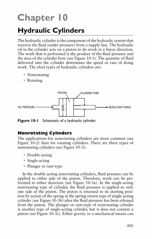
P1: JYC
GB098-10 GB098-Miller September 13, 2004 18:3 Char Count= 0
Chapter 10Hydraulic CylindersThe hydraulic cylinder is the component of the hydraulic system thatreceives the fluid (under pressure) from a supply line. The hydraulicoil in the cylinder acts on a piston to do work in a linear direction.The work that is performed is the product of the fluid pressure andthe area of the cylinder bore (see Figure 10-1). The quantity of fluiddelivered into the cylinder determines the speed or rate of doingwork. The chief types of hydraulic cylinders are:
� Nonrotating� Rotating
PISTON CYLINDER TUBE
RESULTANT FORCEOIL PRESSURE
BORE
Figure 10-1 Schematic of a hydraulic cylinder.
Nonrotating CylindersThe applications for nonrotating cylinders are more common (seeFigure 10-2) than for rotating cylinders. There are three types ofnonrotating cylinders (see Figure 10-3):
� Double-acting� Single-acting� Plunger or ram-type
In the double-acting nonrotating cylinders, fluid pressure can beapplied to either side of the piston. Therefore, work can be per-formed in either direction (see Figure 10-3a). In the single-actingnonrotating type of cylinder, the fluid pressure is applied to onlyone side of the piston. The piston is returned to its starting posi-tion by action of the spring in the spring-return type of single-actingcylinder (see Figure 10-3b) after the fluid pressure has been releasedfrom the piston. The plunger or ram-type of nonrotating cylinderis another type of single-acting cylinder, but it does not contain apiston (see Figure 10-3c). Either gravity or a mechanical means can
405
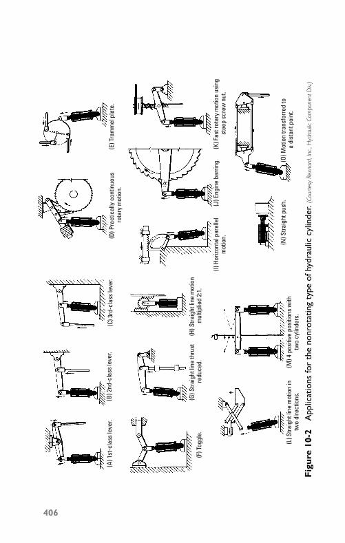
P1: JYC
GB098-10 GB098-Miller September 13, 2004 18:3 Char Count= 0
(A) 1
st-c
lass
leve
r.(B
) 2nd
-cla
ss le
ver.
(C) 3
rd-c
lass
leve
r.
(F) T
oggl
e.(G
) Stra
ight
line
thru
st re
duce
d.
(L) S
traig
ht li
ne m
otio
n in
two
dire
ctio
ns.
(H) S
traig
ht li
ne m
otio
n m
ultip
lied
2:1.
(M) 4
pos
itive
pos
ition
s w
ith
two
cylin
ders
.
(D) P
ract
ical
ly c
ontin
uous
ro
tary
mot
ion.
(E) T
ram
mel
pla
te.
(I) H
orizo
ntal
par
alle
l m
otio
n.
(K) F
ast r
otar
y m
otio
n us
ing
ste
ep s
crew
nut
.(J
) Eng
ine
barr
ing.
(N) S
traig
ht p
ush.
(O) M
otio
n tra
nsfe
rred
to a
dis
tant
poi
nt.
Fig
ure
10-2
App
licat
ions
for
the
nonr
otat
ing
type
ofhy
drau
liccy
linde
r.(C
ourt
esy
Rexn
ard,
Inc.
,Hyd
raul
icCo
mpo
nent
Div.
)
406
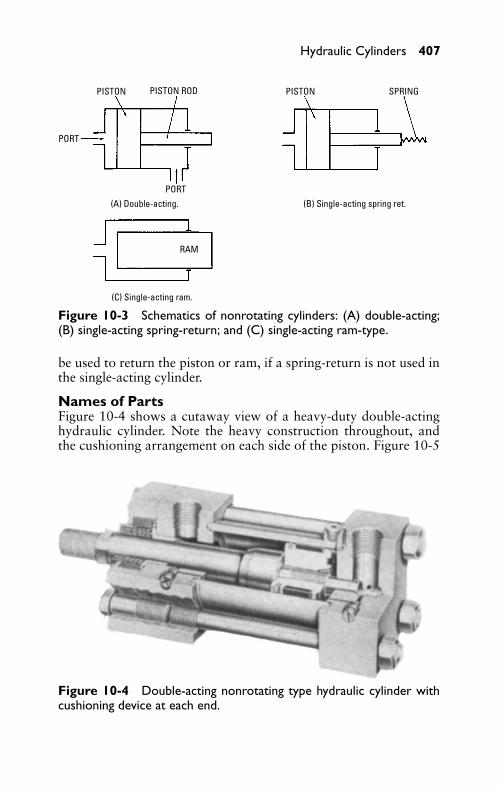
P1: JYC
GB098-10 GB098-Miller September 13, 2004 18:3 Char Count= 0
Hydraulic Cylinders 407
PISTON PISTONPISTON ROD
PORT
PORT
(C) Single-acting ram.
(A) Double-acting. (B) Single-acting spring ret.
RAM
SPRING
Figure 10-3 Schematics of nonrotating cylinders: (A) double-acting;(B) single-acting spring-return; and (C) single-acting ram-type.
be used to return the piston or ram, if a spring-return is not used inthe single-acting cylinder.
Names of PartsFigure 10-4 shows a cutaway view of a heavy-duty double-actinghydraulic cylinder. Note the heavy construction throughout, andthe cushioning arrangement on each side of the piston. Figure 10-5
Figure 10-4 Double-acting nonrotating type hydraulic cylinder withcushioning device at each end.
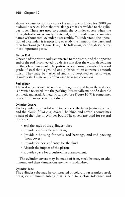
P1: JYC
GB098-10 GB098-Miller September 13, 2004 18:3 Char Count= 0
408 Chapter 10
shows a cross-section drawing of a mill-type cylinder for 2000 psihydraulic service. Note the steel flanges that are welded to the cylin-der tube. These are used to contain the cylinder covers when thethrough-bolts are securely tightened, and provide ease of mainte-nance without total cylinder disassembly. To understand the opera-tion of a cylinder, it is necessary to study the names of the parts andtheir functions (see Figure 10-6). The following sections describe themost important parts.
Piston RodOne end of the piston rod is connected to the piston, and the oppositeend of the rod is connected to a device that does the work, dependingon the job requirement. The piston rods are usually made of a goodgrade of steel that is ground and polished to an extremely smoothfinish. They may be hardened and chrome-plated to resist wear.Stainless steel material is often used to resist corrosion.
Rod WiperThe rod wiper is used to remove foreign material from the rod as itis drawn backward into the packing. It is usually made of a durablesynthetic material. A metallic scraper (see Figure 10-7) is sometimesneeded to remove severe residues.
Cylinder CoversEach cylinder is provided with two covers: the front (rod-end) coverand the blank (blind-end) cover. The blind-end cover is sometimesa part of the tube or cylinder body. The covers are used for severalpurposes:
� Seal the ends of the cylinder tubes� Provide a means for mounting� Provide a housing for seals, rod bearings, and rod packing
(front cover)� Provide for ports of entry for the fluid� Absorb the impact of the piston� Provide space for a cushioning arrangement.
The cylinder covers may be made of iron, steel, bronze, or alu-minum, and their dimensions are well standardized.
Cylinder TubeThe cylinder tube may be constructed of cold-drawn seamless steel,brass, or aluminum tubing that is held to a close tolerance and
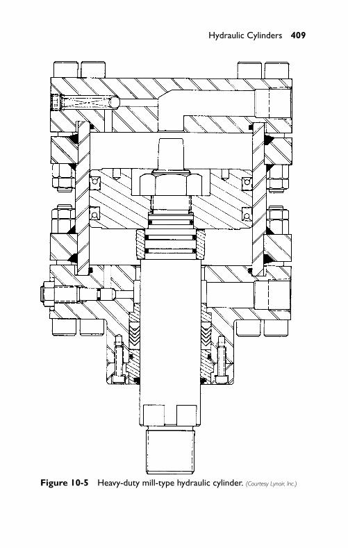
P1: JYC
GB098-10 GB098-Miller September 13, 2004 18:3 Char Count= 0
Hydraulic Cylinders 409
Figure 10-5 Heavy-duty mill-type hydraulic cylinder. (Courtesy Lynair, Inc.)
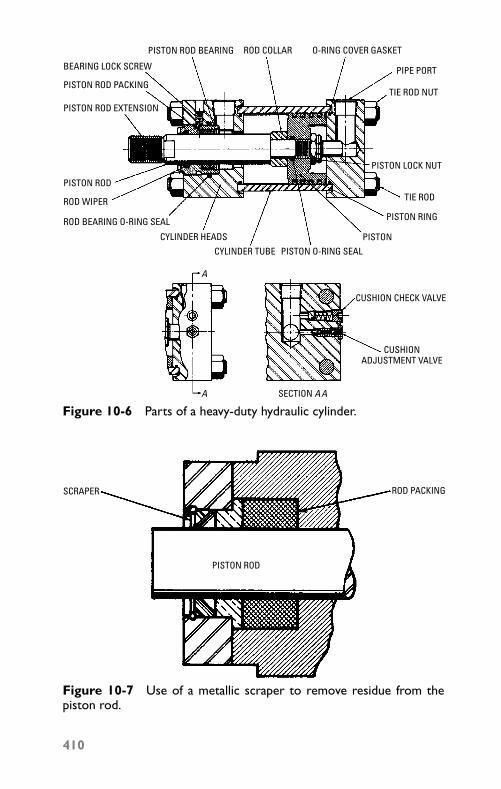
P1: JYC
GB098-10 GB098-Miller September 13, 2004 18:3 Char Count= 0
PISTON ROD BEARING ROD COLLAR O-RING COVER GASKET
PIPE PORT
TIE ROD NUT
PISTON LOCK NUT
TIE ROD
PISTON RING
PISTON O-RING SEAL
ROD BEARING O-RING SEAL
PISTON ROD PACKING
PISTON ROD EXTENSION
PISTON ROD
PISTON
CUSHION CHECK VALVE
CUSHIONADJUSTMENT VALVE
SECTION A A
CYLINDER TUBE
CYLINDER HEADS
BEARING LOCK SCREW
ROD WIPER
A
A
Figure 10-6 Parts of a heavy-duty hydraulic cylinder.
SCRAPER
PISTON ROD
ROD PACKING
Figure 10-7 Use of a metallic scraper to remove residue from thepiston rod.
410
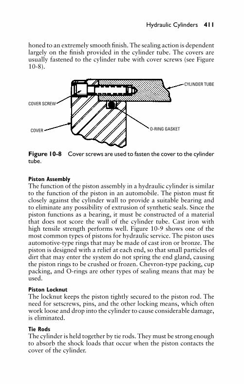
P1: JYC
GB098-10 GB098-Miller September 13, 2004 18:3 Char Count= 0
Hydraulic Cylinders 411
honed to an extremely smooth finish. The sealing action is dependentlargely on the finish provided in the cylinder tube. The covers areusually fastened to the cylinder tube with cover screws (see Figure10-8).
COVER SCREW
COVER
CYLINDER TUBE
O-RING GASKET
Figure 10-8 Cover screws are used to fasten the cover to the cylindertube.
Piston AssemblyThe function of the piston assembly in a hydraulic cylinder is similarto the function of the piston in an automobile. The piston must fitclosely against the cylinder wall to provide a suitable bearing andto eliminate any possibility of extrusion of synthetic seals. Since thepiston functions as a bearing, it must be constructed of a materialthat does not score the wall of the cylinder tube. Cast iron withhigh tensile strength performs well. Figure 10-9 shows one of themost common types of pistons for hydraulic service. The piston usesautomotive-type rings that may be made of cast iron or bronze. Thepiston is designed with a relief at each end, so that small particles ofdirt that may enter the system do not spring the end gland, causingthe piston rings to be crushed or frozen. Chevron-type packing, cuppacking, and O-rings are other types of sealing means that may beused.
Piston LocknutThe locknut keeps the piston tightly secured to the piston rod. Theneed for setscrews, pins, and the other locking means, which oftenwork loose and drop into the cylinder to cause considerable damage,is eliminated.
Tie RodsThe cylinder is held together by tie rods. They must be strong enoughto absorb the shock loads that occur when the piston contacts thecover of the cylinder.
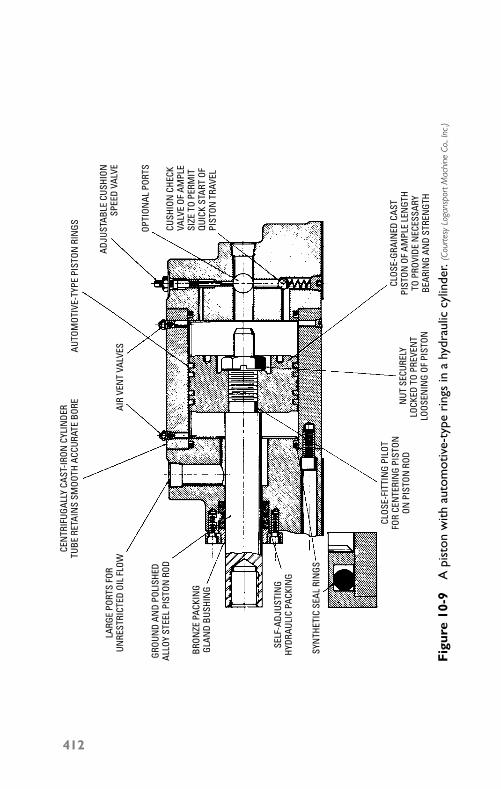
P1: JYC
GB098-10 GB098-Miller September 13, 2004 18:3 Char Count= 0
CEN
TRIF
UGAL
LY C
AST-
IRON
CYL
INDE
RTU
BE R
ETAI
NS
SMOO
TH A
CCUR
ATE
BORE
LARG
E PO
RTS
FOR
UNRE
STRI
CTED
OIL
FLO
W
GROU
ND
AND
POLI
SHED
ALLO
Y ST
EEL
PIST
ON R
OD
BRON
ZE P
ACKI
NG
GLAN
D BU
SHIN
G
SELF
-ADJ
USTI
NG
HYDR
AULI
C PA
CKIN
G
SYN
THET
IC S
EAL
RIN
GS
CLOS
E-FI
TTIN
G PI
LOT
FOR
CEN
TERI
NG
PIST
ONON
PIS
TON
ROD
NUT
SEC
UREL
YLO
CKED
TO
PREV
ENT
LOOS
ENIN
G OF
PIS
TON
CLOS
E-GR
AIN
ED C
AST
PIST
ON O
F AM
PLE
LEN
GTH
TO P
ROVI
DE N
ECES
SARY
BEAR
ING
AND
STRE
NGT
H
CUSH
ION
CHE
CKVA
LVE
OF A
MPL
E SI
ZE T
O PE
RMIT
QUIC
K ST
ART
OFPI
STON
TRA
VEL
OPTI
ONAL
POR
TS
ADJU
STAB
LE C
USHI
ONSP
EED
VALV
E
AUTO
MOT
IVE-
TYPE
PIS
TON
RIN
GS
AIR
VEN
T VA
LVES
Fig
ure
10-9
Api
ston
with
auto
mot
ive-
type
ring
sin
ahy
drau
liccy
linde
r.(C
ourt
esy
Loga
nspo
rtM
achi
neCo
.,In
c.)
412
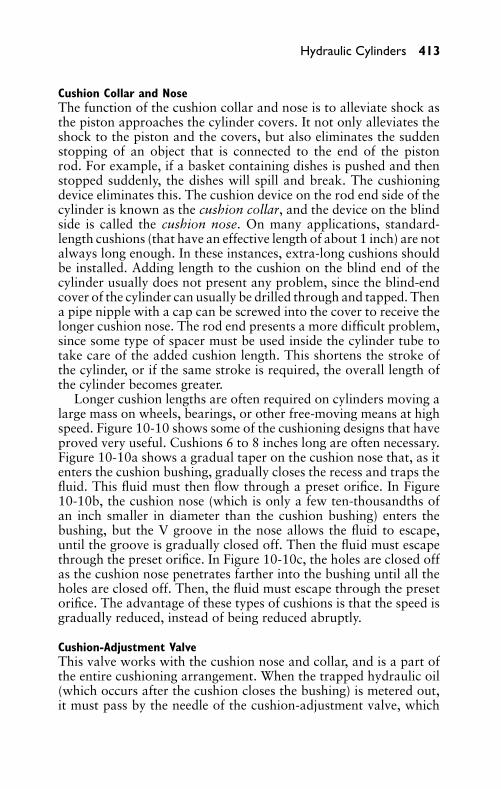
P1: JYC
GB098-10 GB098-Miller September 13, 2004 18:3 Char Count= 0
Hydraulic Cylinders 413
Cushion Collar and NoseThe function of the cushion collar and nose is to alleviate shock asthe piston approaches the cylinder covers. It not only alleviates theshock to the piston and the covers, but also eliminates the suddenstopping of an object that is connected to the end of the pistonrod. For example, if a basket containing dishes is pushed and thenstopped suddenly, the dishes will spill and break. The cushioningdevice eliminates this. The cushion device on the rod end side of thecylinder is known as the cushion collar, and the device on the blindside is called the cushion nose. On many applications, standard-length cushions (that have an effective length of about 1 inch) are notalways long enough. In these instances, extra-long cushions shouldbe installed. Adding length to the cushion on the blind end of thecylinder usually does not present any problem, since the blind-endcover of the cylinder can usually be drilled through and tapped. Thena pipe nipple with a cap can be screwed into the cover to receive thelonger cushion nose. The rod end presents a more difficult problem,since some type of spacer must be used inside the cylinder tube totake care of the added cushion length. This shortens the stroke ofthe cylinder, or if the same stroke is required, the overall length ofthe cylinder becomes greater.
Longer cushion lengths are often required on cylinders moving alarge mass on wheels, bearings, or other free-moving means at highspeed. Figure 10-10 shows some of the cushioning designs that haveproved very useful. Cushions 6 to 8 inches long are often necessary.Figure 10-10a shows a gradual taper on the cushion nose that, as itenters the cushion bushing, gradually closes the recess and traps thefluid. This fluid must then flow through a preset orifice. In Figure10-10b, the cushion nose (which is only a few ten-thousandths ofan inch smaller in diameter than the cushion bushing) enters thebushing, but the V groove in the nose allows the fluid to escape,until the groove is gradually closed off. Then the fluid must escapethrough the preset orifice. In Figure 10-10c, the holes are closed offas the cushion nose penetrates farther into the bushing until all theholes are closed off. Then, the fluid must escape through the presetorifice. The advantage of these types of cushions is that the speed isgradually reduced, instead of being reduced abruptly.
Cushion-Adjustment ValveThis valve works with the cushion nose and collar, and is a part ofthe entire cushioning arrangement. When the trapped hydraulic oil(which occurs after the cushion closes the bushing) is metered out,it must pass by the needle of the cushion-adjustment valve, which
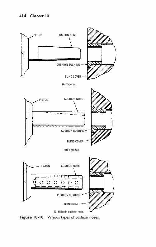
P1: JYC
GB098-10 GB098-Miller September 13, 2004 18:3 Char Count= 0
414 Chapter 10
PISTON CUSHION NOSE
CUSHION BUSHING
BLIND COVER
(A) Tapered.
PISTON
PISTON
CUSHION NOSE
CUSHION NOSE
CUSHION BUSHING
CUSHION BUSHING
BLIND COVER
BLIND COVER
(B) V groove.
(C) Holes in cushion nose.
Figure 10-10 Various types of cushion noses.
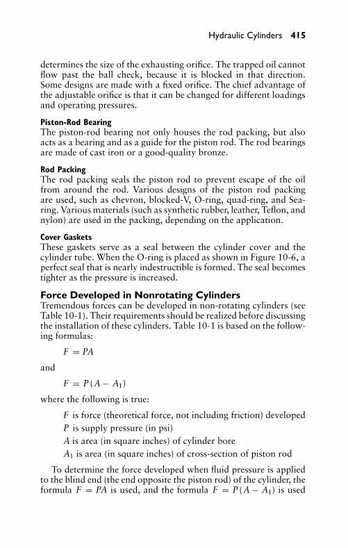
P1: JYC
GB098-10 GB098-Miller September 13, 2004 18:3 Char Count= 0
Hydraulic Cylinders 415
determines the size of the exhausting orifice. The trapped oil cannotflow past the ball check, because it is blocked in that direction.Some designs are made with a fixed orifice. The chief advantage ofthe adjustable orifice is that it can be changed for different loadingsand operating pressures.
Piston-Rod BearingThe piston-rod bearing not only houses the rod packing, but alsoacts as a bearing and as a guide for the piston rod. The rod bearingsare made of cast iron or a good-quality bronze.
Rod PackingThe rod packing seals the piston rod to prevent escape of the oilfrom around the rod. Various designs of the piston rod packingare used, such as chevron, blocked-V, O-ring, quad-ring, and Sea-ring. Various materials (such as synthetic rubber, leather, Teflon, andnylon) are used in the packing, depending on the application.
Cover GasketsThese gaskets serve as a seal between the cylinder cover and thecylinder tube. When the O-ring is placed as shown in Figure 10-6, aperfect seal that is nearly indestructible is formed. The seal becomestighter as the pressure is increased.
Force Developed in Nonrotating CylindersTremendous forces can be developed in non-rotating cylinders (seeTable 10-1). Their requirements should be realized before discussingthe installation of these cylinders. Table 10-1 is based on the follow-ing formulas:
F = PA
and
F = P (A − A1)
where the following is true:
F is force (theoretical force, not including friction) developedP is supply pressure (in psi)A is area (in square inches) of cylinder boreA1 is area (in square inches) of cross-section of piston rod
To determine the force developed when fluid pressure is appliedto the blind end (the end opposite the piston rod) of the cylinder, theformula F = PA is used, and the formula F = P (A − A1) is used
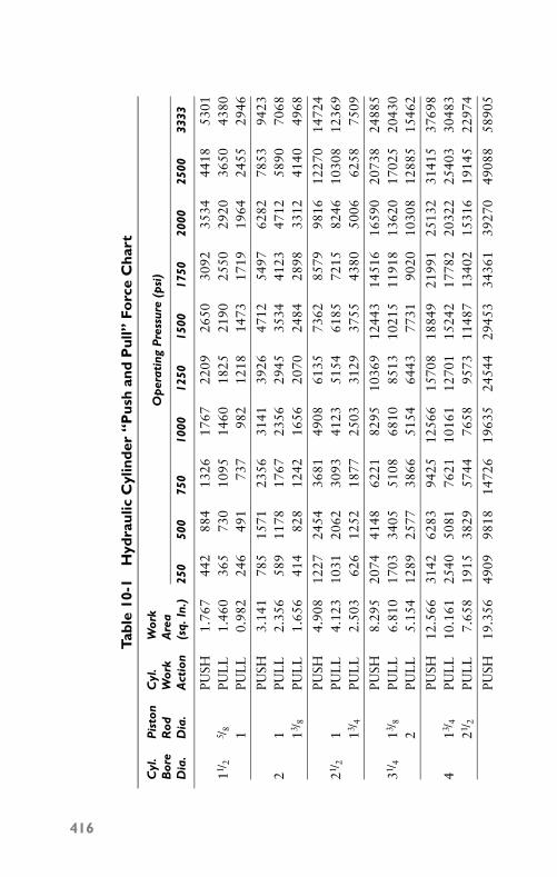
P1: JYC
GB098-10 GB098-Miller September 13, 2004 18:3 Char Count= 0
Tabl
e10
-1H
ydra
ulic
Cyl
inde
r“P
ush
and
Pul
l”Fo
rce
Cha
rt
Cyl
.P
isto
nC
yl.
Wor
kB
ore
Rod
Wor
kA
rea
Op
erat
ing
Pre
ssur
e(p
si)
Dia
.D
ia.
Act
ion
(sq.
In.)
250
500
750
1000
1250
1500
1750
2000
2500
3333
PUSH
1.76
744
288
413
2617
6722
0926
5030
9235
3444
1853
0111 /
25 /
8PU
LL
1.46
036
573
010
9514
6018
2521
9025
5029
2036
5043
801
PUL
L0.
982
246
491
737
982
1218
1473
1719
1964
2455
2946
PUSH
3.14
178
515
7123
5631
4139
2647
1254
9762
8278
5394
232
1PU
LL
2.35
658
911
7817
6723
5629
4535
3441
2347
1258
9070
6813 /
8PU
LL
1.65
641
482
812
4216
5620
7024
8428
9833
1241
4049
68
PUSH
4.90
812
2724
5436
8149
0861
3573
6285
7998
1612
270
1472
421 /
21
PUL
L4.
123
1031
2062
3093
4123
5154
6185
7215
8246
1030
812
369
13 /4
PUL
L2.
503
626
1252
1877
2503
3129
3755
4380
5006
6258
7509
PUSH
8.29
520
7441
4862
2182
9510
369
1244
314
516
1659
020
738
2488
531 /
413 /
8PU
LL
6.81
017
0334
0551
0868
1085
1310
215
1191
813
620
1702
520
430
2PU
LL
5.15
412
8925
7738
6651
5464
4377
3190
2010
308
1288
515
462
PUSH
12.5
6631
4262
8394
2512
566
1570
818
849
2199
125
132
3141
537
698
413 /
4PU
LL
10.1
6125
4050
8176
2110
161
1270
115
242
1778
220
322
2540
330
483
21 /2
PUL
L7.
658
1915
3829
5744
7658
9573
1148
713
402
1531
619
145
2297
4
PUSH
19.3
5649
0998
1814
726
1963
524
544
2945
334
361
3927
049
088
5890
5
416
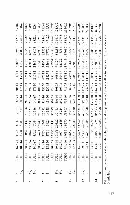
P1: JYC
GB098-10 GB098-Miller September 13, 2004 18:3 Char Count= 0
52
PUL
L16
.494
4124
8247
1237
116
494
2061
824
741
2886
532
988
4123
549
482
31 /2
PUL
L10
.014
2504
5007
7511
1001
412
518
1502
117
525
2002
825
035
3004
2
PUSH
28.2
7470
6914
137
2120
628
274
3534
342
411
4948
056
548
7068
584
822
621 /
2PU
LL
23.3
6658
4211
683
1752
523
366
2920
835
049
4089
146
732
5841
570
098
41 /4
PUL
L14
.088
3522
7044
1056
614
088
1761
021
132
2465
428
176
3522
042
264
PUSH
38.4
8596
2119
243
2886
438
485
4810
657
728
6734
976
970
9621
311
5455
73
PUL
L31
.416
7854
1570
823
562
3141
639
270
4712
454
978
6283
278
540
9424
85
PUL
L18
.850
4713
9425
1413
818
850
2356
328
275
3368
837
700
4712
556
550
PUSH
50.2
6512
566
2513
337
689
5026
552
831
7539
887
964
1005
3012
5663
1507
958
31 /2
PUL
L40
.644
1016
120
322
3048
340
644
5080
560
966
7112
781
288
1016
1012
1932
53 /4
PUL
L24
.298
6074
1214
918
224
2429
830
373
3644
742
522
4859
660
745
7289
4
PUSH
78.5
4019
635
3927
058
905
7854
098
175
1178
1013
7445
1570
8019
6350
2356
2010
41 /2
PUL
L62
.636
1565
931
318
4697
762
636
7829
593
954
1096
1312
5272
1565
9018
7908
53 /4
PUL
L52
.573
1314
326
287
3943
052
573
6571
678
860
9200
310
5146
1314
3315
7719
PUSH
113.
1028
275
5655
084
825
1131
0014
1375
1696
5019
7925
2262
0028
2750
3393
0012
51 /2
PUL
L89
.34
2233
544
670
6700
589
340
1116
7513
4010
1563
4517
8680
2233
5026
8020
7PU
LL
74.6
119
653
3730
555
958
7461
093
263
1119
1513
0568
1492
2019
6525
2238
30
PUSH
153.
9438
485
7697
011
5455
1539
4019
2425
2309
1026
9395
3078
8038
4850
4618
2014
7PU
LL
115.
4528
863
5772
586
593
1154
5014
4313
1731
7520
2038
2309
0028
8625
3463
5010
PUL
L75
.40
1885
037
700
5655
075
400
9425
011
3100
1319
5015
0800
1885
0022
6200
Thi
sch
art
lists
theo
reti
calv
alue
spr
oduc
edby
vari
ous
wor
king
pres
sure
san
ddo
esno
tal
low
for
loss
due
tofr
icti
on. C
ourt
esy
LynA
ir,In
c.
417
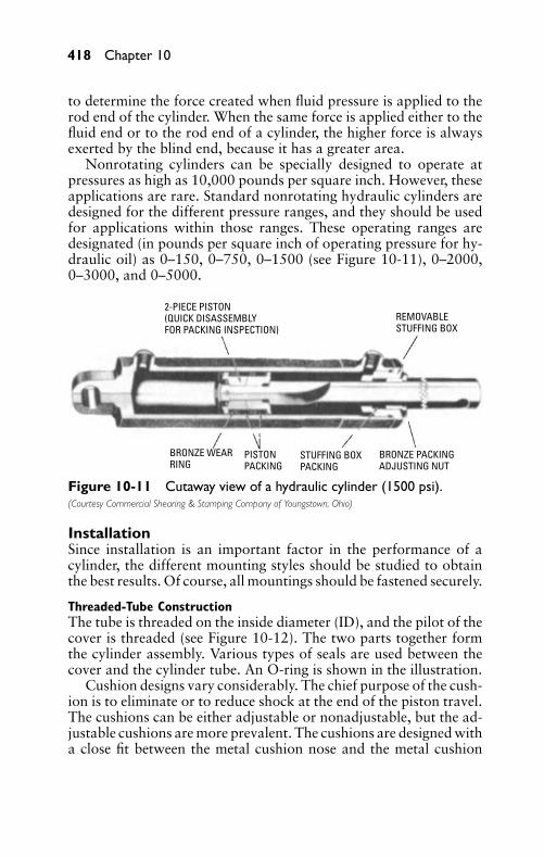
P1: JYC
GB098-10 GB098-Miller September 13, 2004 18:3 Char Count= 0
418 Chapter 10
to determine the force created when fluid pressure is applied to therod end of the cylinder. When the same force is applied either to thefluid end or to the rod end of a cylinder, the higher force is alwaysexerted by the blind end, because it has a greater area.
Nonrotating cylinders can be specially designed to operate atpressures as high as 10,000 pounds per square inch. However, theseapplications are rare. Standard nonrotating hydraulic cylinders aredesigned for the different pressure ranges, and they should be usedfor applications within those ranges. These operating ranges aredesignated (in pounds per square inch of operating pressure for hy-draulic oil) as 0–150, 0–750, 0–1500 (see Figure 10-11), 0–2000,0–3000, and 0–5000.
2-PIECE PISTON(QUICK DISASSEMBLYFOR PACKING INSPECTION)
REMOVABLESTUFFING BOX
BRONZE PACKINGADJUSTING NUT
STUFFING BOXPACKING
BRONZE WEARRING
PISTONPACKING
Figure 10-11 Cutaway view of a hydraulic cylinder (1500 psi).(Courtesy Commercial Shearing & Stamping Company of Youngstown, Ohio)
InstallationSince installation is an important factor in the performance of acylinder, the different mounting styles should be studied to obtainthe best results. Of course, all mountings should be fastened securely.
Threaded-Tube ConstructionThe tube is threaded on the inside diameter (ID), and the pilot of thecover is threaded (see Figure 10-12). The two parts together formthe cylinder assembly. Various types of seals are used between thecover and the cylinder tube. An O-ring is shown in the illustration.
Cushion designs vary considerably. The chief purpose of the cush-ion is to eliminate or to reduce shock at the end of the piston travel.The cushions can be either adjustable or nonadjustable, but the ad-justable cushions are more prevalent. The cushions are designed witha close fit between the metal cushion nose and the metal cushion
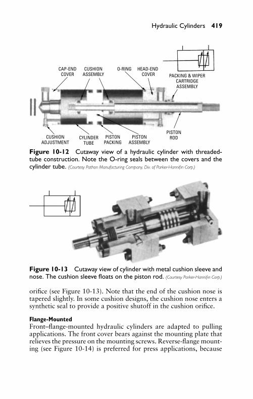
P1: JYC
GB098-10 GB098-Miller September 13, 2004 18:3 Char Count= 0
Hydraulic Cylinders 419
CAP-END COVER
CUSHION ASSEMBLY
O-RING HEAD-END COVER PACKING & WIPER
CARTRIDGE ASSEMBLY
PISTON RODPISTON
ASSEMBLYPISTON
PACKINGCYLINDER
TUBECUSHION
ADJUSTMENT
Figure 10-12 Cutaway view of a hydraulic cylinder with threaded-tube construction. Note the O-ring seals between the covers and thecylinder tube. (Courtesy Pathon Manufacturing Company, Div. of Parker-Hannifin Corp.)
Figure 10-13 Cutaway view of cylinder with metal cushion sleeve andnose. The cushion sleeve floats on the piston rod. (Courtesy Parker-Hannifin Corp.)
orifice (see Figure 10-13). Note that the end of the cushion nose istapered slightly. In some cushion designs, the cushion nose enters asynthetic seal to provide a positive shutoff in the cushion orifice.
Flange-MountedFront–flange-mounted hydraulic cylinders are adapted to pullingapplications. The front cover bears against the mounting plate thatrelieves the pressure on the mounting screws. Reverse-flange mount-ing (see Figure 10-14) is preferred for press applications, because
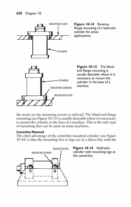
P1: JYC
GB098-10 GB098-Miller September 13, 2004 18:3 Char Count= 0
420 Chapter 10
MOUNTING PLATE
CYLINDER
Figure 10-14 Reverse-flange mounting of a hydrauliccylinder for pressapplications.
CYLINDER
MOUNTING SCREWS
MOUNTING PLATE
Figure 10-15 The blind-end flange mounting isusually desirable where it isnecessary to mount thecylinder in the base of amachine.
the strain on the mounting screws is relieved. The blind-end flangemounting (see Figure 10-15) is usually desirable where it is necessaryto mount the cylinder in the base of a machine. This is the only typeof mounting that can be used on some machines.
Centerline-MountedThe chief advantage of the centerline-mounted cylinder (see Figure10-16) is that the mounting feet or lugs are in a direct line with the
MOUNTING SCREW
BACKUP BLOCK Figure 10-16 Hydrauliccylinder with mounting lugs atthe centerline.
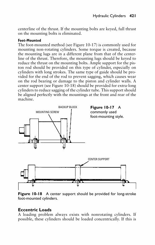
P1: JYC
GB098-10 GB098-Miller September 13, 2004 18:3 Char Count= 0
Hydraulic Cylinders 421
centerline of the thrust. If the mounting bolts are keyed, full thruston the mounting bolts is eliminated.
Foot-MountedThe foot-mounted method (see Figure 10-17) is commonly used formounting non-rotating cylinders. Some torque is created, becausethe mounting lugs are in a different plane from that of the center-line of the thrust. Therefore, the mounting lugs should be keyed toreduce the thrust on the mounting bolts. Ample support for the pis-ton rod should be provided on this type of cylinder, especially oncylinders with long strokes. The same type of guide should be pro-vided for the end of the rod to prevent sagging, which causes wearon the rod bearing or damage to the piston and cylinder walls. Acenter support (see Figure 10-18) should be provided for extra-longcylinders to reduce sagging of the cylinder tube. This support shouldbe aligned perfectly with the mountings at the front and rear of themachine.
MOUNTING SCREW
BACKUP BLOCK Figure 10-17 Acommonly usedfoot-mounting style.
CENTER SUPPORT
Figure 10-18 A center support should be provided for long-strokefoot-mounted cylinders.
Eccentric LoadsA loading problem always exists with nonrotating cylinders. Ifpossible, these cylinders should be loaded concentrically. If this is
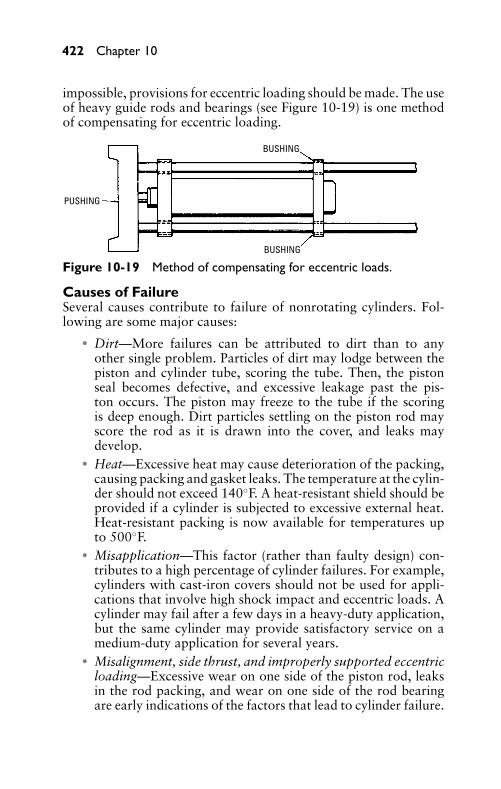
P1: JYC
GB098-10 GB098-Miller September 13, 2004 18:3 Char Count= 0
422 Chapter 10
impossible, provisions for eccentric loading should be made. The useof heavy guide rods and bearings (see Figure 10-19) is one methodof compensating for eccentric loading.
BUSHING
BUSHING
PUSHING
Figure 10-19 Method of compensating for eccentric loads.
Causes of FailureSeveral causes contribute to failure of nonrotating cylinders. Fol-lowing are some major causes:
� Dirt—More failures can be attributed to dirt than to anyother single problem. Particles of dirt may lodge between thepiston and cylinder tube, scoring the tube. Then, the pistonseal becomes defective, and excessive leakage past the pis-ton occurs. The piston may freeze to the tube if the scoringis deep enough. Dirt particles settling on the piston rod mayscore the rod as it is drawn into the cover, and leaks maydevelop.
� Heat—Excessive heat may cause deterioration of the packing,causing packing and gasket leaks. The temperature at the cylin-der should not exceed 140◦F. A heat-resistant shield should beprovided if a cylinder is subjected to excessive external heat.Heat-resistant packing is now available for temperatures upto 500◦F.
� Misapplication—This factor (rather than faulty design) con-tributes to a high percentage of cylinder failures. For example,cylinders with cast-iron covers should not be used for appli-cations that involve high shock impact and eccentric loads. Acylinder may fail after a few days in a heavy-duty application,but the same cylinder may provide satisfactory service on amedium-duty application for several years.
� Misalignment, side thrust, and improperly supported eccentricloading—Excessive wear on one side of the piston rod, leaksin the rod packing, and wear on one side of the rod bearingare early indications of the factors that lead to cylinder failure.
P1: JYC
GB098-10 GB098-Miller September 13, 2004 18:3 Char Count= 0
Hydraulic Cylinders 423
A bent piston rod, a broken packing gland, a scored cylindertube, a broken cylinder cover, or a broken piston may resultin serious damage.
� Faulty mountings—If the mounting is not secure (or is notstrong enough to withstand the load produced by the cylinder),the cylinder may break loose and damage the mounting or theapplication with that it is connected.
Repair and MaintenanceSuggestions for dismantling, repairing, and assembling nonrotatingcylinders are as follows:
� Drain all oil from the cylinder, and dismantle in a clean loca-tion. Do not attempt to dismantle a cylinder when pressure isapplied to the cylinder.
� Each part should be cleaned. Metal parts that are to be reusedshould be coated with a good preservative and placed in pro-tective storage if the cylinder is to remain dismantled.
� The piston rod should be checked for straightness. If the rod isbent, it can be straightened by placing it in V blocks in a press.The piston rod should be examined for scores, indentations,and scratches. If the blemishes are not too deep, they can beremoved with a fine emery cloth. However, if it is necessary togrind the rod, it can be chrome-plated to restore the diameterto its original size.
� The cover and cushion bushings should be examined for wearand finish, and they should be replaced if they are not in first-class condition.
� The cylinder tube should be repaired or replaced if it is dam-aged. Deep scores are difficult to repair, and it may be necessaryto chrome-plate the tube.
� All the seals and gaskets should be replaced during reassemblyof a cylinder. If metal piston rings are used, the manufacturer’sspecifications should be checked for gap clearance. If syntheticor leather seals are used on the piston, care should be exercisedin placing the piston in the tube, so that the sealing surfaces arenot damaged. When installing the packing, light grease makesassembly much easier.
� If a metal piston with rings is to be replaced, grind the pistonconcentrically with the piston rod after assembly to the rod.Grind the piston to fit the tube closely.
P1: JYC
GB098-10 GB098-Miller September 13, 2004 18:3 Char Count= 0
424 Chapter 10
� Cylinders with foot-mounted covers should be assembled on asurface plate. The mounting pads of both covers should makefull contact with the surface plate. Otherwise, a binding ac-tion may occur after mounting, or a mounting foot may bebroken.
� The cover bolts should be tightened evenly. If O-ring or quad-ring gaskets are used to seal the tube and cover, tension on thecover screw is reduced to a minimum.
After assembly of a cylinder has been completed, it should betested at low operating pressure for freedom of movement of thepiston and rod, and to ensure that they are not being scored orbound. Then the pressure should be increased to the full operat-ing range, and the cylinder checked for both internal and externalleakages.
To check for internal leakage, place fluid pressure in the blind-end port of the cylinder, forcing the piston to the rod end; thencheck the amount of fluid coming from the rod and cover port.Try placing fluid pressure in the rod-end port, moving the pistonto the blind-end cover, and check for leakage at this position. Ifleakage is to be checked at other positions, use an external meansto block the ports at these positions and check as described earlier.When excessive leakage occurs, the cylinder must be disassembledto make corrections. If metal piston rings are used in a hydrauliccylinder, the leakage varies with the operating pressure, the cylin-der bore, and the oil temperature and viscosity. Leakage should benearly nonexistent if the piston is sealed with synthetic or leatherseals.
A cylinder should be mounted securely when it is reattached to amachine or fixture. It should always be remembered that these cylin-ders are capable of delivering considerable force. Cylinder boresmay range from 1 inch in diameter to more than 30 inches in di-ameter. The strokes may range from less than 1 inch to more than30 feet.
Rotating CylindersA study of the names of the parts and their functions is necessary tounderstand the operation of a rotating cylinder. Figure 10-20 showsa rotating hydraulic cylinder.
Names of PartsThe following sections describe the important parts of a rotatingcylinder.
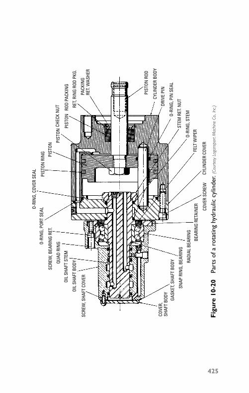
P1: JYC
GB098-10 GB098-Miller September 13, 2004 18:3 Char Count= 0
O-RI
NG,
COV
ER S
EAL
O-RI
NG,
POR
T SE
AL
SCRE
W, B
EARI
NG
RET.
QUAD
RIN
G
OIL
SHAF
T ST
EM
OIL
SHAF
T BO
DY
SCRE
W, S
HAFT
COV
ER
COVE
R,SH
AFT
BODY
GASK
ET, S
HAFT
BOD
Y
SNAP
RIN
G, B
EARI
NG
BEAR
ING
RETA
INER
RADI
AL B
EARI
NG
COVE
R SC
REW
CYLI
NDE
R CO
VER
FELT
WIP
ER
O-RI
NG,
STE
M
STEM
RET
. NUT
O-RI
NG,
PIN
SEA
L
DRIV
E PI
N
CYLI
NDE
R BO
DY
PIST
ON R
OD
PIST
ON R
ING PIST
ON
PIST
ON
PIST
ON
ROD
PACK
ING
RET,
RIN
G RO
D PK
G.
CHEC
K N
UT
PACK
ING
RET.
WAS
HER
Fig
ure
10-2
0Pa
rts
ofa
rota
ting
hydr
aulic
cylin
der.
(Cou
rtes
yLo
gans
port
Mac
hine
Co.,
Inc.
)
425
P1: JYC
GB098-10 GB098-Miller September 13, 2004 18:3 Char Count= 0
426 Chapter 10
BodyThe cylinder body is usually made of either cast iron or aluminum,and it must be pressure-tight. The body is usually matched on boththe inside and the outside surfaces (on the inside surface to providea smooth surface for the packing and on the outside surface forthe sake of appearance). The body contains passages for directingthe fluid to the front side of the piston. In addition, it contains thehousing for the rod packing, and provides a bearing for the pistonrod. A number of tapped holes are provided in the open end ofthe body to receive the cover bolts. The closed end of the bodyis provided with an adaptation designed to meet either AmericanStandards or the manufacturer’s specifications. The body may alsoanchor one end of the drive pin.
If the cylinders are designed with a stroke that is longer thanthe standard stroke, the body often consists of two sections: thecylinder tube and the rod-end cover. This design aids in reducingporosity that is often a problem on long-stroke rotating cylinderswith a one-piece body.
Cylinder CoverThe cover is fastened to the body by cover screws, and it encloses thecylinder. The cylinder cover carries the oil shaft assembly, and mayanchor one end of the drive pin. The cover carries a fluid passagethat connects to the fluid passage in the cylinder body.
Piston RodThe piston rod is made of a ground and polished alloy steel, and is theconnector between the piston and the driven means. The end of thepiston is usually tapped with female threads, but some applicationsmay require male threads.
Piston AssemblyAn automotive-type piston ring is used in the piston assembly of thehydraulic cylinder shown in Figure 10-20. Other designs use varioustypes of seals, such as V packing or blocked-Vs. The piston may bemade of either cast iron or aluminum. The piston has three chieffunctions:
� Provide an area for the fluid pressure to exert force, therebydeveloping a force to act on a load.
� Provide a seal that prevents leaking or escaping of fluid to theexhaust side.
� Act as a guide or bearing.
P1: JYC
GB098-10 GB098-Miller September 13, 2004 18:3 Char Count= 0
Hydraulic Cylinders 427
Drive PinsThese pins prevent rotation of the piston in relation to the cylinderbody. Drive pins are needed because brakes are provided on manymachines with rotating spindles. Without the drive pins, a suddenstopping of the spindle may cause the piston to rotate within thecylinder body, causing the piston rod to become loosened or dis-connected from its connecting part. This often causes considerabletrouble, and considerable time is consumed in correcting it.
Rod PackingSince most of the work is usually done on the in-stroke, and fluidpressure is exerted on the rod packing most of the time, the rodpacking is extremely important in a rotating cylinder. The efficiencyon the in-stroke is reduced greatly by any leakage past the packing.On rotating cylinders, it is a quite difficult job to make a packingchange. Therefore, the packing must be durable. Synthetic rubber,impregnated leather, Teflon, and other materials are used for pack-ing. Several designs (such as chevron, Sea rings, and hat) are usedfor packing.
Cover GasketThis gasket seals the cylinder body and the cylinder cover, and itcontains holes for the cover screws and for the fluid passages be-tween the body and the cover. Although the cover gasket can bemade of a thin sheet of gasket material, it must be strong enough toprevent escape of the fluid.
Oil Shaft StemThis is an important part of the action of the rotating cylinder. Theshaft stem must be sturdy enough to provide proper support tothe remainder of the oil shaft-assembly and to withstand externalforce that results from the weight of the flexible hoses and pipeconnectors. The oil shaft stem is made of hardened alloy steel andground to a high finish, so that the packing is provided with a smoothbearing surface. An oil shaft assembly is often referred to as an oildistributor.
Distributor BodyThe distributor body functions as a housing for the shaft packing. Italso functions as a housing for the means of lubrication, to provideports of entry, and to retain the bearing. The body may be made ofsuch materials as cast iron, cast aluminum, or cast bronze. It shouldbe arranged to dissipate as much heat as possible from the packingand the shaft, and the body must be rugged enough to withstand
P1: JYC
GB098-10 GB098-Miller September 13, 2004 18:3 Char Count= 0
428 Chapter 10
the strain of the pipelines and connectors. Water-cooled distributorbodies containing large-cored passages are often necessary to effecta better cooling action where hollow oil shafts are used.
Shaft PackingAs little friction as possible must be created by the shaft packing.However, it must provide an effective seal at shaft revolutions up to5000 rpm and higher. Shredded lead, lead and graphite, asbestos,and other materials are used to combat the heat condition. Variouspacking shapes (such as formed-wedge,V, and hat types) are used.
BearingA bearing is required to provide support between the shaft bodyand the shaft stem. Depending on the shaft design, various typesof bearings, such as ball bearings, sleeve, and thrust bearings, areused. These bearings must be able to withstand considerable heat,and lubrication to the bearings is extremely important.
Other PartsA number of minor parts are important in the function of a rotatingcylinder. Some of these parts are: retainer rings, spacers, O-ring gas-kets, and screws. Incorrect assembly of these minor parts or failureto replace worn or damaged seals, gaskets, and so on, may causethe cylinder to malfunction or to fail to operate properly, resultingin increased maintenance and repair costs.
InstallationThe pressure chart shown in Table 10-1 should be studied before ac-tual installation of a rotating cylinder is begun, if you are to visualizethe great force that these cylinders can develop. Although pneumaticrotating cylinders are seldom operated at more than 90 pounds of airpressure, hydraulic rotating cylinders may be operated at pressuresas high as 1000 psi.
Since the rotating cylinder may be subjected to high revolvingspeeds, installation is an extremely important factor. As mentionedpreviously, rotating cylinders are constructed with the mountingas a part of the cylinder body. On the small-diameter cylinders,the mounting is usually threaded. A number of tapped holes formounting purposes are used on the larger cylinders.
Rotating cylinders are not mounted directly onto the machinespindle. They are mounted on an adapter that has previously beenmounted onto the machine spindle. Adapters are used because themanufacturers of lathes and other machines with spindles use dif-ferent end designs on the cylinder end of the machine spindle. If
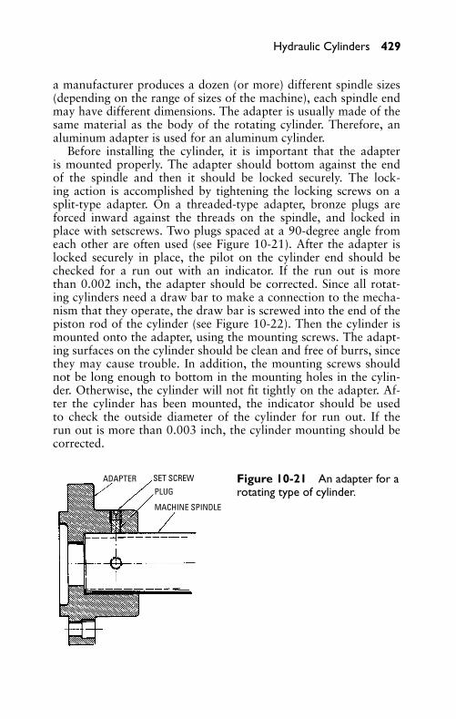
P1: JYC
GB098-10 GB098-Miller September 13, 2004 18:3 Char Count= 0
Hydraulic Cylinders 429
a manufacturer produces a dozen (or more) different spindle sizes(depending on the range of sizes of the machine), each spindle endmay have different dimensions. The adapter is usually made of thesame material as the body of the rotating cylinder. Therefore, analuminum adapter is used for an aluminum cylinder.
Before installing the cylinder, it is important that the adapteris mounted properly. The adapter should bottom against the endof the spindle and then it should be locked securely. The lock-ing action is accomplished by tightening the locking screws on asplit-type adapter. On a threaded-type adapter, bronze plugs areforced inward against the threads on the spindle, and locked inplace with setscrews. Two plugs spaced at a 90-degree angle fromeach other are often used (see Figure 10-21). After the adapter islocked securely in place, the pilot on the cylinder end should bechecked for a run out with an indicator. If the run out is morethan 0.002 inch, the adapter should be corrected. Since all rotat-ing cylinders need a draw bar to make a connection to the mecha-nism that they operate, the draw bar is screwed into the end of thepiston rod of the cylinder (see Figure 10-22). Then the cylinder ismounted onto the adapter, using the mounting screws. The adapt-ing surfaces on the cylinder should be clean and free of burrs, sincethey may cause trouble. In addition, the mounting screws shouldnot be long enough to bottom in the mounting holes in the cylin-der. Otherwise, the cylinder will not fit tightly on the adapter. Af-ter the cylinder has been mounted, the indicator should be usedto check the outside diameter of the cylinder for run out. If therun out is more than 0.003 inch, the cylinder mounting should becorrected.
ADAPTER SET SCREW
PLUG
MACHINE SPINDLE
Figure 10-21 An adapter for arotating type of cylinder.
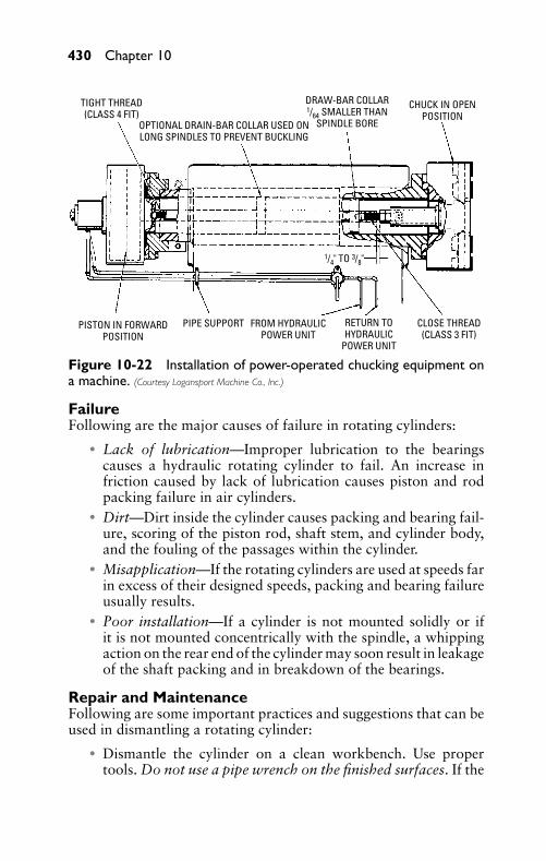
P1: JYC
GB098-10 GB098-Miller September 13, 2004 18:3 Char Count= 0
430 Chapter 10
PISTON IN FORWARDPOSITION
PIPE SUPPORT FROM HYDRAULICPOWER UNIT
RETURN TOHYDRAULIC
POWER UNIT
CLOSE THREAD(CLASS 3 FIT)
TIGHT THREAD(CLASS 4 FIT)
OPTIONAL DRAIN-BAR COLLAR USED ONLONG SPINDLES TO PREVENT BUCKLING
DRAW-BAR COLLAR1/64 SMALLER THAN
SPINDLE BORE
CHUCK IN OPENPOSITION
1/4" TO 3/8"
Figure 10-22 Installation of power-operated chucking equipment ona machine. (Courtesy Logansport Machine Co., Inc.)
FailureFollowing are the major causes of failure in rotating cylinders:
� Lack of lubrication—Improper lubrication to the bearingscauses a hydraulic rotating cylinder to fail. An increase infriction caused by lack of lubrication causes piston and rodpacking failure in air cylinders.
� Dirt—Dirt inside the cylinder causes packing and bearing fail-ure, scoring of the piston rod, shaft stem, and cylinder body,and the fouling of the passages within the cylinder.
� Misapplication—If the rotating cylinders are used at speeds farin excess of their designed speeds, packing and bearing failureusually results.
� Poor installation—If a cylinder is not mounted solidly or ifit is not mounted concentrically with the spindle, a whippingaction on the rear end of the cylinder may soon result in leakageof the shaft packing and in breakdown of the bearings.
Repair and MaintenanceFollowing are some important practices and suggestions that can beused in dismantling a rotating cylinder:
� Dismantle the cylinder on a clean workbench. Use propertools. Do not use a pipe wrench on the finished surfaces. If the
P1: JYC
GB098-10 GB098-Miller September 13, 2004 18:3 Char Count= 0
Hydraulic Cylinders 431
cylinder is placed in a vise, use soft pads and do not apply toomuch pressure to the cylinder body. Loosen the rod-packingretainer. Then, remove the cover screws, take off the cover,and remove the piston and piston rod.
� Each part should be cleaned thoroughly as it is removed. Partswith internal passages should be cleaned out with compressedair. A protective coating should be applied to steel or ironparts, and the parts placed in protected storage if the cylinderis to be dismantled for a prolonged length of time.
� Score marks in the cylinder body should be eliminated, or thebody should be scrapped if the scores are too deep. In a cast-iron body, the marks can be brazed, and then the interior ofthe body can be refinished.
� If the piston rod is scored, the marks may be removed with afine emery cloth, unless they are too deep, in which case it isprobably cheaper to replace the rod.
� It is advisable to replace all packing and seals when the cylin-der is disassembled. In installing cup packing, apply enoughtension so that they do not leak, but do not apply enough ten-sion to turn in the lips. If the piston parts are designed to makemetal-to-metal contact, too much cam pressure may damagethe cups.
� If the rod bearing in the cylinder body is worn, it should bereplaced. If the rod bearing is part of the body, there is stockenough (in the body) to bore out and press in a bronze sleeve-type bearing. The bearing must be tight.
� A worn or scored oil shaft should be replaced, because this isa vital part of the cylinder. Any rough portions on the shaftcan be a source of trouble.
� In reassembly, all screws should be tightened securely. Tightenthe cover screws evenly. Care should be exercised to preventcuts in the packing and gaskets as they are placed.
� After the cylinder has been reassembled and before applyingpressure, lubricate and rotate the distributor body to ensurethat it moves freely and without any binding action.
� Apply fluid pressure to one port of the distributor body, andcheck piston movement. Place a finger over the pipe port tocheck for leaks. Then shift the pressure connection to the sec-ond port, let the piston move to the end of its travel, and placea finger over the first port to check for leaks. Slight packing
P1: JYC
GB098-10 GB098-Miller September 13, 2004 18:3 Char Count= 0
432 Chapter 10
leaks that are caused by a slight blow of the shaft can usuallybe taken care of after the cylinder has been run in, by pullingupward on the shaft packing. If excessive leakage occurs, thecylinder should be dismantled.
SummaryThe hydraulic cylinder receives the fluid (under pressure) from asupply line. The oil in the cylinder acts on a piston to do work ina linear direction. The work that is performed is the product of thefluid pressure and the area of the cylinder bore. The chief types ofhydraulic cylinders are nonrotating and rotating.
Three types of nonrotating cylinders are available: double acting,single acting and plunger or ram-type. In the double-acting cylinders,fluid pressure can be applied to either side of the piston. Therefore,work can be performed in either direction. Fluid pressure is appliedto only one side of the piston in a single-acting cylinder. The pis-ton is returned to its starting position by action of the spring in aspring-return type of single-acting cylinder. The plunger or ram-typecylinder is another type of single-acting cylinder.
Tremendous forces can be developed in non-rotating cylinders. Todetermine the force developed when pressure is applied to the blindend (the end opposite the piston rod) of the cylinder, the formula F= PA is used. The formula F = P (A − A1) is used to determine theforce created when fluid pressure is applied to the rod end of thecylinder.
Standard nonrotating hydraulic cylinders are designed for thedifferent pressure ranges, and they should be used for applica-tions within these ranges. These operating ranges are designated(in pounds per square inch of operating pressure) as 0–150, 0–750,0–1500, 0–2000, 0–3000, and 0–5000.
Installation is an important factor in the performance of a nonro-tating cylinder. The different styles of mounting these cylinders areflange-mounted, centerline-mounted, and foot-mounted.
The installation of rotating cylinders is extremely important, be-cause these cylinders often revolve at high speeds. These cylinders arenot mounted directly onto the machine spindle. They are mountedon an adapter that has previously been mounted onto the spindle.Therefore, it is important that both the adapter and the cylinder areinstalled correctly.
Review Questions1. What is the chief difference between single-acting and double-
acting hydraulic cylinders?
P1: JYC
GB098-10 GB098-Miller September 13, 2004 18:3 Char Count= 0
Hydraulic Cylinders 433
2. What is an application for a nonrotating cylinder?3. What is the purpose of a cushion collar and nose?4. List three factors that may cause a nonrotating cylinder to fail.5. Name at least five types of seals that are used on the pistons.6. List four factors that may cause a rotating cylinder to fail.7. Name four types of piston rod seals.8. How can a nonrotating cylinder be used in conjunction with
a rotating cylinder?9. Name two types of cylinder cover seals.
10. What materials are generally used in cylinder covers?11. Draw the schematic of a hydraulic cylinder and label the parts.12. What is the purpose of a cushion adjustment valve?13. Draw the symbol for a hydraulic cylinder with threaded tube
construction.14. What is the most commonly used method for mounting non-
rotating cylinders?15. How can leakage be reduced to a bare minimum in a hydraulic
cylinder?16. Identify six important parts of a rotating hydraulic cylinder.17. What are the major causes of rotating cylinder failure?18. How can dirt cause damage to a rotating cylinder?19. What are three different styles of mounting cylinders?20. How are standard non-rotating hydraulic cylinders designated
as to pressure ranges?21. What is an application for a rotating cylinder?

P1: JYC
GB098-10 GB098-Miller September 13, 2004 18:3 Char Count= 0
434
P1: FCH
GB098-11 GB098-Miller September 13, 2004 18:4 Char Count= 0
Chapter 11Control ValvesThe control valves that are used in hydraulic systems can be dividedinto three categories:
� Pressure controls� Flow controls� Directional controls
Pressure controls regulate the pressure intensity in the variousportions of the system. Flow controls regulate the speed at whichthe hydraulic fluid is permitted to flow. This, in turn, controls thepiston speed in the cylinders, the movement of the valve spools,the rotation speeds of the shafts of fluid motors, and the actua-tion speeds of other devices. Directional controls are used to di-rect the hydraulic fluid to the various passages in the system. Manytypes of directional controls are available—from the simple shut-off valves (similar to those used on sill-cocks in the home) to thesix- and eight-way control valves that are used to control automaticmachinery.
The size of its external openings determines the size of a controlvalve (or the amount of fluid that can pass through the openingwith minimum backpressure). For example, a control valve withexternal openings or pipe ports threaded for a 1/2-inch pipe shouldbe capable of passing the same amount of fluid that can be passednormally by a 1/2-inch pipe. Generally, the flow of hydraulic fluiddoes not exceed 15 feet per second. However, in some instances,the oil velocity far exceeds this rate, and it may be nearly twice thisrate. Excessive velocities of hydraulic fluid create heat in the system,and they contribute to control problems that arise from undesirablepressure drops.
Sub-plate mountings (see Figure 11-1) or manifold-type mount-ings are often used for control valves. Then the control valve can bereplaced without disturbing the piping.
Flange-type connections (see Figure 11-2) are used on many of thelarger control valves. These connections are usually used for portsthat are larger than 2 inches, and they are used mostly in hydraulicsfor military or mobile applications (see Figure 11-3).
Materials that are used in construction of a control valve dependlargely on the fluid medium, the operating pressure, and the ambienttemperature. The bodies of hydraulic valves are made of high-tensile
435
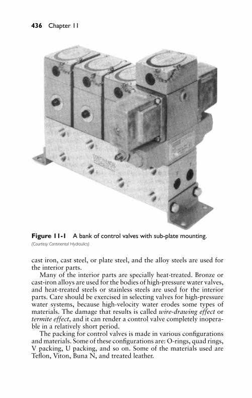
P1: FCH
GB098-11 GB098-Miller September 13, 2004 18:4 Char Count= 0
436 Chapter 11
Figure 11-1 A bank of control valves with sub-plate mounting.(Courtesy Continental Hydraulics)
cast iron, cast steel, or plate steel, and the alloy steels are used forthe interior parts.
Many of the interior parts are specially heat-treated. Bronze orcast-iron alloys are used for the bodies of high-pressure water valves,and heat-treated steels or stainless steels are used for the interiorparts. Care should be exercised in selecting valves for high-pressurewater systems, because high-velocity water erodes some types ofmaterials. The damage that results is called wire-drawing effect ortermite effect, and it can render a control valve completely inopera-ble in a relatively short period.
The packing for control valves is made in various configurationsand materials. Some of these configurations are: O-rings, quad rings,V packing, U packing, and so on. Some of the materials used areTeflon, Viton, Buna N, and treated leather.
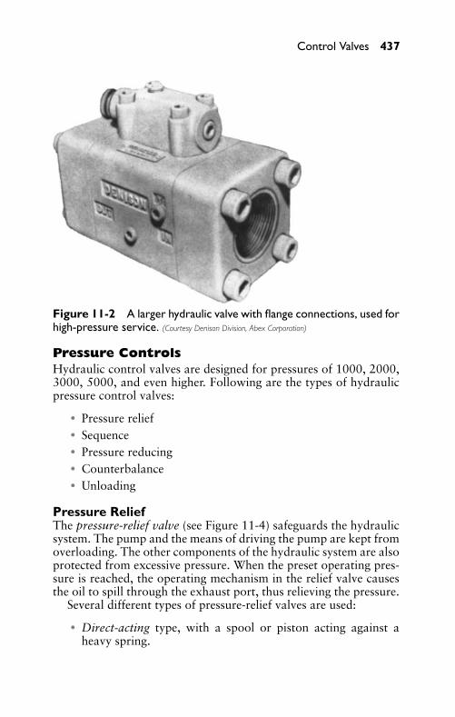
P1: FCH
GB098-11 GB098-Miller September 13, 2004 18:4 Char Count= 0
Control Valves 437
Figure 11-2 A larger hydraulic valve with flange connections, used forhigh-pressure service. (Courtesy Denison Division, Abex Corporation)
Pressure ControlsHydraulic control valves are designed for pressures of 1000, 2000,3000, 5000, and even higher. Following are the types of hydraulicpressure control valves:
� Pressure relief� Sequence� Pressure reducing� Counterbalance� Unloading
Pressure ReliefThe pressure-relief valve (see Figure 11-4) safeguards the hydraulicsystem. The pump and the means of driving the pump are kept fromoverloading. The other components of the hydraulic system are alsoprotected from excessive pressure. When the preset operating pres-sure is reached, the operating mechanism in the relief valve causesthe oil to spill through the exhaust port, thus relieving the pressure.
Several different types of pressure-relief valves are used:
� Direct-acting type, with a spool or piston acting against aheavy spring.
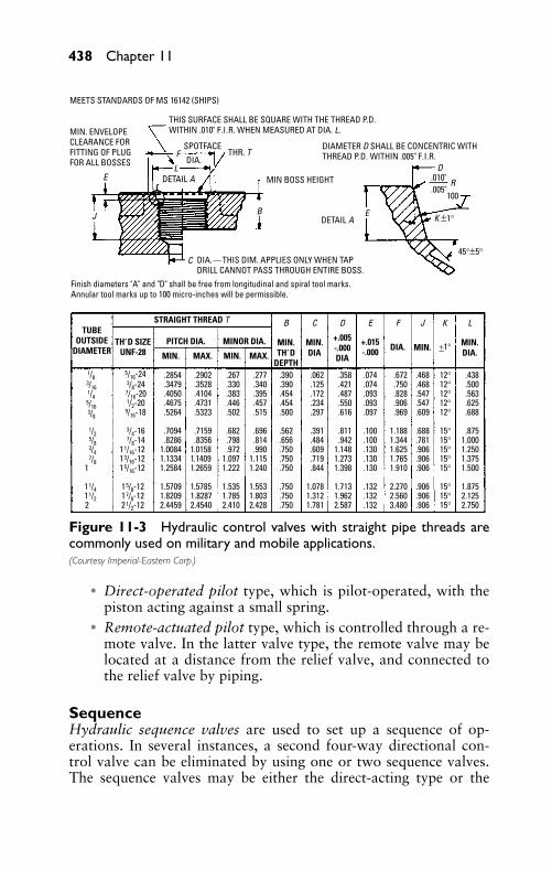
P1: FCH
GB098-11 GB098-Miller September 13, 2004 18:4 Char Count= 0
438 Chapter 11
MEETS STANDARDS OF MS 16142 (SHIPS)
SPOTFACEF
MIN. ENVELOPECLEARANCE FORFITTING OF PLUGFOR ALL BOSSES
B
Finish diameters "A" and "D" shall be free from longitudinal and spiral tool marks.Annular tool marks up to 100 micro-inches will be permissible.
DIAMETER D SHALL BE CONCENTRIC WITHTHREAD P.D. WITHIN .005" F.I.R.
DIA.—THIS DIM. APPLIES ONLY WHEN TAPDRILL CANNOT PASS THROUGH ENTIRE BOSS.
MIN BOSS HEIGHT
100
E K ±1°
R
45°±5°
D.010".005"
J
EL
C
B
MIN.TH‘ D
DEPTH
MIN.DIA
MIN.DIA.
MIN. +1°DIA.+.005-.000DIA
+.015-.000
C D E F J K L
MIN.
.2854
.34793/8-24
.4050
.4675
.5264
.7094
.82861.00841.13341.2584
1.57091.82092.4459
5/16-24
7/16-201/2-20
9/16-18
3/4-167/8-14
11/16-1213/16-1215/16-12
15/8-1217/8-1221/2-12
3/16
1/8
1/45/163/8
1/25/83/47/8
1
11/411/22
.2902
.3528
.4104
.4731
.5323
.7159
.83561.01581.14091.2659
1.57851.82872.4540
.267
.330
.383
.446
.502
.682
.798
.9721.0971.222
1.5351.7852.410
.277
.340
.395
.457
.515
.696
.814
.9901.1151.240
1.5531.8032.428
.390
.390
.454
.454
.500
.562
.656
.750
.750
.750
.750
.750
.750
.062
.125
.172
.234
.297
.391
.484
.609
.719
.844
1.0781.3121.781
.358
.421
.487
.550
.616
.811
.9421.1481.2731.398
1.7131.9622.587
.074
.074
.093
.093
.097
.100
.100
.130
.130
.130
.132
.132
.132
.672
.750
.828
.906
.969
1.1881.3441.6251.7651.910
2.2702.5603.480
.468
.468
.547
.547
.609
.688
.781
.906
.906
.906
.906
.906
.906
.438
.500
.563
.625
.688
.8751.0001.2501.3751.500
1.8752.1252.750
12°12°12°12°12°
15°15°15°15°15°
15°15°15°
MIN.MAX. MAX.
PITCH DIA. MINOR DIA.TH‘D SIZEUNF-28
TUBEOUTSIDE
DIAMETER
STRAIGHT THREAD T
DETAIL A
DETAIL A
THR. TDIA.
THIS SURFACE SHALL BE SQUARE WITH THE THREAD P.D.WITHIN .010" F.I.R. WHEN MEASURED AT DIA. L.
−
Figure 11-3 Hydraulic control valves with straight pipe threads arecommonly used on military and mobile applications.(Courtesy Imperial-Eastern Corp.)
� Direct-operated pilot type, which is pilot-operated, with thepiston acting against a small spring.
� Remote-actuated pilot type, which is controlled through a re-mote valve. In the latter valve type, the remote valve may belocated at a distance from the relief valve, and connected tothe relief valve by piping.
SequenceHydraulic sequence valves are used to set up a sequence of op-erations. In several instances, a second four-way directional con-trol valve can be eliminated by using one or two sequence valves.The sequence valves may be either the direct-acting type or the
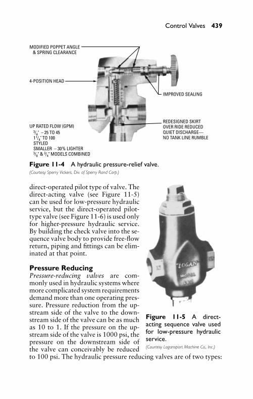
P1: FCH
GB098-11 GB098-Miller September 13, 2004 18:4 Char Count= 0
Control Valves 439
MODIFIED POPPET ANGLE& SPRING CLEARANCE
4-POSITION HEAD
IMPROVED SEALING
REDESIGNED SKIRTOVER RIDE REDUCEDQUIET DISCHARGE—NO TANK LINE RUMBLE
UP RATED FLOW (GPM)3/4" − 25 TO 4511/4" TO 100STYLEDSMALLER − 30% LIGHTER3/8" & 3/4" MODELS COMBINED
Figure 11-4 A hydraulic pressure-relief valve.(Courtesy Sperry Vickers, Div. of Sperry Rand Corp.)
Figure 11-5 A direct-acting sequence valve usedfor low-pressure hydraulicservice.(Courtesy Logansport Machine Co., Inc.)
direct-operated pilot type of valve. Thedirect-acting valve (see Figure 11-5)can be used for low-pressure hydraulicservice, but the direct-operated pilot-type valve (see Figure 11-6) is used onlyfor higher-pressure hydraulic service.By building the check valve into the se-quence valve body to provide free-flowreturn, piping and fittings can be elim-inated at that point.
Pressure ReducingPressure-reducing valves are com-monly used in hydraulic systems wheremore complicated system requirementsdemand more than one operating pres-sure. Pressure reduction from the up-stream side of the valve to the down-stream side of the valve can be as muchas 10 to 1. If the pressure on the up-stream side of the valve is 1000 psi, thepressure on the downstream side ofthe valve can conceivably be reducedto 100 psi. The hydraulic pressure reducing valves are of two types:
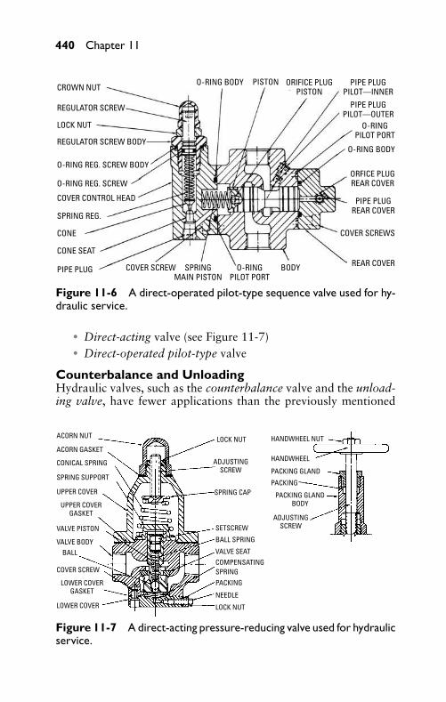
P1: FCH
GB098-11 GB098-Miller September 13, 2004 18:4 Char Count= 0
440 Chapter 11
CROWN NUTPISTON ORIFICE PLUG
PISTON
REGULATOR SCREW
LOCK NUT
O-RING REG. SCREW BODY
O-RING REG. SCREW
COVER CONTROL HEAD
SPRING REG.
CONE
CONE SEAT
PIPE PLUG COVER SCREW SPRINGMAIN PISTON
BODY REAR COVER
COVER SCREWS
ORFICE PLUGREAR COVER
PIPE PLUGREAR COVER
O-RINGPILOT PORT
O-RINGPILOT PORT
O-RING BODY
O-RING BODY PIPE PLUGPILOT—INNER
REGULATOR SCREW BODY
PIPE PLUGPILOT—OUTER
Figure 11-6 A direct-operated pilot-type sequence valve used for hy-draulic service.
� Direct-acting valve (see Figure 11-7)� Direct-operated pilot-type valve
Counterbalance and UnloadingHydraulic valves, such as the counterbalance valve and the unload-ing valve, have fewer applications than the previously mentioned
ACORN NUT LOCK NUT HANDWHEEL NUT
HANDWHEEL
PACKING GLAND
PACKING
ADJUSTINGSCREW
PACKING GLANDBODY
SPRING CAP
SETSCREW
BALL SPRING
VALVE SEATCOMPENSATINGSPRINGPACKING
NEEDLE
LOCK NUT
ADJUSTINGSCREW
ACORN GASKET
CONICAL SPRING
SPRING SUPPORT
UPPER COVER
VALVE PISTON
VALVE BODYBALL
COVER SCREW
LOWER COVER
LOWER COVERGASKET
UPPER COVERGASKET
Figure 11-7 A direct-acting pressure-reducing valve used for hydraulicservice.
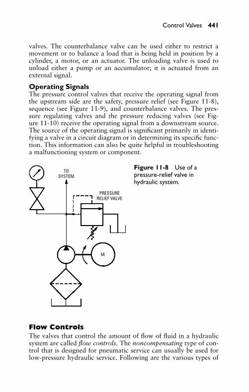
P1: FCH
GB098-11 GB098-Miller September 13, 2004 18:4 Char Count= 0
Control Valves 441
valves. The counterbalance valve can be used either to restrict amovement or to balance a load that is being held in position by acylinder, a motor, or an actuator. The unloading valve is used tounload either a pump or an accumulator; it is actuated from anexternal signal.
Operating SignalsThe pressure control valves that receive the operating signal fromthe upstream side are the safety, pressure relief (see Figure 11-8),sequence (see Figure 11-9), and counterbalance valves. The pres-sure regulating valves and the pressure reducing valves (see Fig-ure 11-10) receive the operating signal from a downstream source.The source of the operating signal is significant primarily in identi-fying a valve in a circuit diagram or in determining its specific func-tion. This information can also be quite helpful in troubleshootinga malfunctioning system or component.
TOSYSTEM
PRESSURERELIEF VALVE
M
Figure 11-8 Use of apressure-relief valve inhydraulic system.
Flow ControlsThe valves that control the amount of flow of fluid in a hydraulicsystem are called flow controls. The noncompensating type of con-trol that is designed for pneumatic service can usually be used forlow-pressure hydraulic service. Following are the various types of
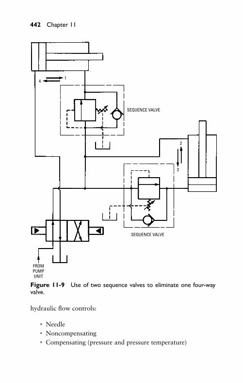
P1: FCH
GB098-11 GB098-Miller September 13, 2004 18:4 Char Count= 0
442 Chapter 11
SEQUENCE VALVE
SEQUENCE VALVE
2
41
3
FROMPUMPUNIT
Figure 11-9 Use of two sequence valves to eliminate one four-wayvalve.
hydraulic flow controls:
� Needle� Noncompensating� Compensating (pressure and pressure temperature)
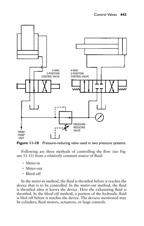
P1: FCH
GB098-11 GB098-Miller September 13, 2004 18:4 Char Count= 0
Control Valves 443
4-WAY,2-POSITION
CONTROL VALVE
FROMPUMPUNIT
PRESSURE-REDUCINGVALVE
4-WAY,3-POSITIONCONTROL VALVE
Figure 11-10 Pressure-reducing valve used in two pressure systems.
Following are three methods of controlling the flow (see Fig-ure 11-11) from a relatively constant source of fluid:
� Meter-in� Meter-out� Bleed-off
In the meter-in method, the fluid is throttled before it reaches thedevice that is to be controlled. In the meter-out method, the fluidis throttled after it leaves the device. Here the exhausting fluid isthrottled. In the bleed-off method, a portion of the hydraulic fluidis bled off before it reaches the device. The devices mentioned maybe cylinders, fluid motors, actuators, or large controls.
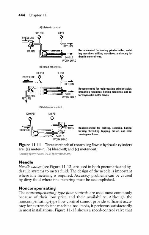
P1: FCH
GB098-11 GB098-Miller September 13, 2004 18:4 Char Count= 0
444 Chapter 11
(A) Meter-in control.
900 PSI 0 PSI
900 PSI
1000 PSI 120 PSI
0 PSI
(B) Bleed-off control.
(C) Meter-out control.
PRESSURE
DRAIN
DRAIN
DRAIN
RETURN
RETURN
PRESSURE
PRESSURE
RETURN
RETURN
5400 LBWORK LOAD
5400 LBWORK LOAD
5400 LBWORK LOAD
Recommended for drilling, reaming, boring, turning, threading, tapping, cut-off, and cold sawing machines.
Recommended for feeding grinder tables, weld-ing machines, milling machines, and rotary hy-draulic motor drives.
Recommended for reciprocating grinder tables, broaching machines, honing machines, and ro-tary hydraulic motor drives.
Figure 11-11 Three methods of controlling flow in hydraulic cylindersare: (a) meter-in; (b) bleed-off; and (c) meter-out.(Courtesy Sperry Vickers, Div. of Sperry Rand Corp.)
NeedleNeedle valves (see Figure 11-12) are used in both pneumatic and hy-draulic systems to meter fluid. The design of the needle is importantwhere fine metering is required. Accuracy problems can be causedby dirty fluid where fine metering must be accomplished.
NoncompensatingThe noncompensating-type flow controls are used most commonlybecause of their low price and their availability. Although thenoncompensating-type flow control cannot provide sufficient accu-racy for extremely fine machine-tool feeds, it performs satisfactorilyin most installations. Figure 11-13 shows a speed-control valve that
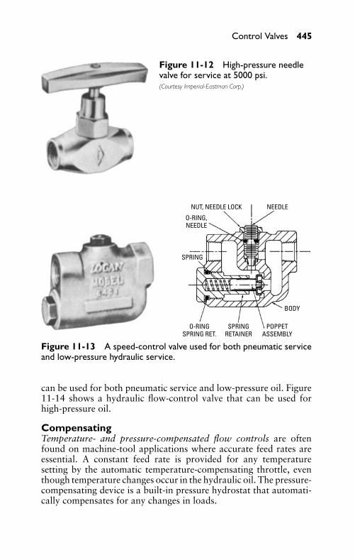
P1: FCH
GB098-11 GB098-Miller September 13, 2004 18:4 Char Count= 0
Control Valves 445
Figure 11-12 High-pressure needlevalve for service at 5000 psi.(Courtesy Imperial-Eastman Corp.)
NUT, NEEDLE LOCK NEEDLE
SPRING
BODY
POPPETASSEMBLY
SPRINGRETAINER
O-RINGSPRING RET.
O-RING,NEEDLE
Figure 11-13 A speed-control valve used for both pneumatic serviceand low-pressure hydraulic service.
can be used for both pneumatic service and low-pressure oil. Figure11-14 shows a hydraulic flow-control valve that can be used forhigh-pressure oil.
CompensatingTemperature- and pressure-compensated flow controls are oftenfound on machine-tool applications where accurate feed rates areessential. A constant feed rate is provided for any temperaturesetting by the automatic temperature-compensating throttle, eventhough temperature changes occur in the hydraulic oil. The pressure-compensating device is a built-in pressure hydrostat that automati-cally compensates for any changes in loads.
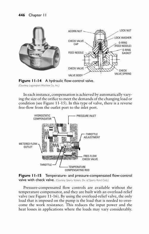
P1: FCH
GB098-11 GB098-Miller September 13, 2004 18:4 Char Count= 0
446 Chapter 11
ACORN NUT LOCK NUT
O-RING(FEED NEEDLE)
CHECK VALVECAP
LOCK WASHER
O-RINGGASKETFEED NEEDLE
CHECK VALVE
VALVE BODY
CHECKVALVE SPRING
Figure 11-14 A hydraulic flow-control valve.(Courtesy Logansport Machine Co., Inc.)
In each instance, compensation is achieved by automatically vary-ing the size of the orifice to meet the demands of the changing load orcondition (see Figure 11-15). In this type of valve, there is a reversefree-flow from the outlet port to the inlet port.
HYDROSTATICCOMPENSATOR
PRESSURE INLET
THROTTLE
METERED FLOWOUTLET
TEMPERATURECOMPENSATING ROD
FREE-FLOWCHECK VALVE
THROTTLEADJUSTMENT
Figure 11-15 Temperature- and pressure-compensated flow-controlvalve with check valve. (Courtesy Sperry Vickers, Div. of Sperry Rand Corp.)
Pressure-compensated flow controls are available without thetemperature compensator, and they are built with an overload-reliefvalve (see Figure 11-16). By using the overload-relief valve, the onlyload that is imposed on the pump is the load that is needed to over-come the work resistance. This reduces the input power and theheat losses in applications where the loads may vary considerably.
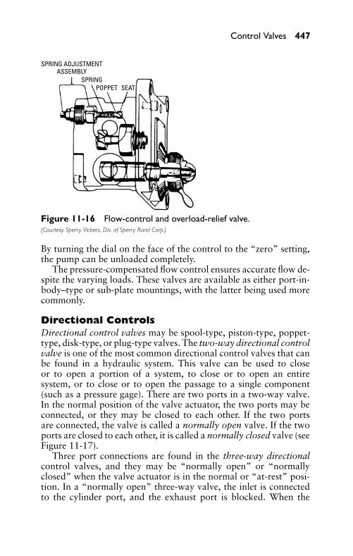
P1: FCH
GB098-11 GB098-Miller September 13, 2004 18:4 Char Count= 0
Control Valves 447
SPRING ADJUSTMENTASSEMBLY
SPRINGPOPPET SEAT
Figure 11-16 Flow-control and overload-relief valve.(Courtesy Sperry Vickers, Div. of Sperry Rand Corp.)
By turning the dial on the face of the control to the “zero” setting,the pump can be unloaded completely.
The pressure-compensated flow control ensures accurate flow de-spite the varying loads. These valves are available as either port-in-body–type or sub-plate mountings, with the latter being used morecommonly.
Directional ControlsDirectional control valves may be spool-type, piston-type, poppet-type, disk-type, or plug-type valves. The two-way directional controlvalve is one of the most common directional control valves that canbe found in a hydraulic system. This valve can be used to closeor to open a portion of a system, to close or to open an entiresystem, or to close or to open the passage to a single component(such as a pressure gage). There are two ports in a two-way valve.In the normal position of the valve actuator, the two ports may beconnected, or they may be closed to each other. If the two portsare connected, the valve is called a normally open valve. If the twoports are closed to each other, it is called a normally closed valve (seeFigure 11-17).
Three port connections are found in the three-way directionalcontrol valves, and they may be “normally open” or “normallyclosed” when the valve actuator is in the normal or “at-rest” posi-tion. In a “normally open” three-way valve, the inlet is connectedto the cylinder port, and the exhaust port is blocked. When the
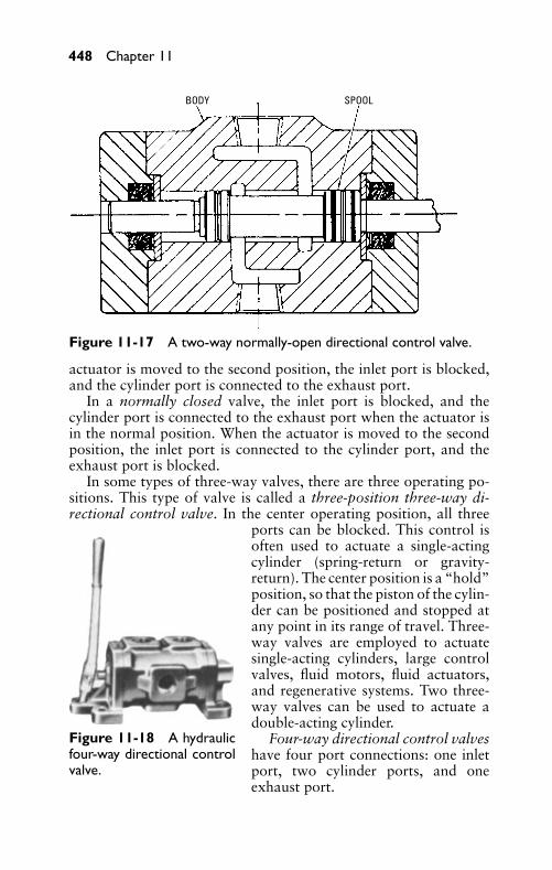
P1: FCH
GB098-11 GB098-Miller September 13, 2004 18:4 Char Count= 0
448 Chapter 11
BODY SPOOL
Figure 11-17 A two-way normally-open directional control valve.
actuator is moved to the second position, the inlet port is blocked,and the cylinder port is connected to the exhaust port.
In a normally closed valve, the inlet port is blocked, and thecylinder port is connected to the exhaust port when the actuator isin the normal position. When the actuator is moved to the secondposition, the inlet port is connected to the cylinder port, and theexhaust port is blocked.
In some types of three-way valves, there are three operating po-sitions. This type of valve is called a three-position three-way di-rectional control valve. In the center operating position, all three
Figure 11-18 A hydraulicfour-way directional controlvalve.
ports can be blocked. This control isoften used to actuate a single-actingcylinder (spring-return or gravity-return). The center position is a “hold”position, so that the piston of the cylin-der can be positioned and stopped atany point in its range of travel. Three-way valves are employed to actuatesingle-acting cylinders, large controlvalves, fluid motors, fluid actuators,and regenerative systems. Two three-way valves can be used to actuate adouble-acting cylinder.
Four-way directional control valveshave four port connections: one inletport, two cylinder ports, and oneexhaust port.
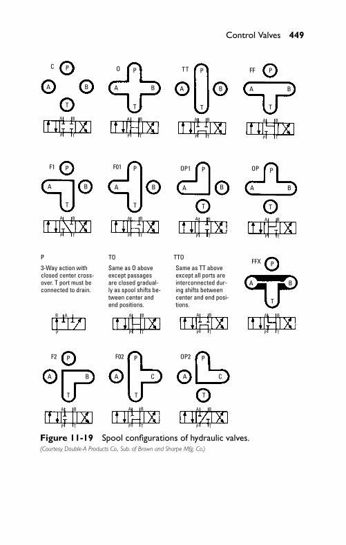
P1: FCH
GB098-11 GB098-Miller September 13, 2004 18:4 Char Count= 0
Control Valves 449
C
A B
P T
A B
P T
A B
P T
A B
P T
A B
P T
A B
P T
A B
P T
A B
P T
AA BB
PP T
A B
P T
A B
P T
A B
P T
A B
P T
A B
P T
B
T
AA
A A A A
A B
BB BB
B A A BB
P
P P P P
P
T
T TT
A A AB C C
P P P
T T T
T
P P P
TTT
F1
P
F2 F02 OP2
TO TTOFFX
F01 OP1 OP
O TT FF
Same as TT above except all ports are interconnected dur-ing shifts between center and end posi-tions.
Same as O above except passages are closed gradual-ly as spool shifts be-tween center and end positions.
3-Way action with closed center cross-over. T port must be connected to drain.
Figure 11-19 Spool configurations of hydraulic valves.(Courtesy Double-A Products Co., Sub. of Brown and Sharpe Mfg. Co.)
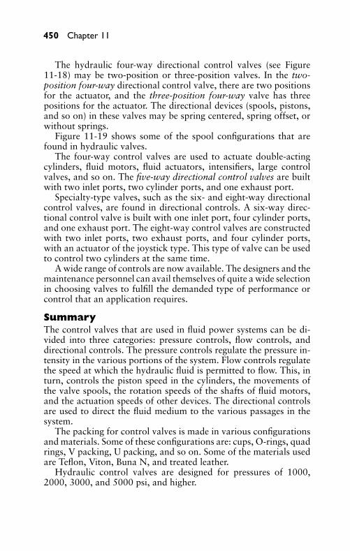
P1: FCH
GB098-11 GB098-Miller September 13, 2004 18:4 Char Count= 0
450 Chapter 11
The hydraulic four-way directional control valves (see Figure11-18) may be two-position or three-position valves. In the two-position four-way directional control valve, there are two positionsfor the actuator, and the three-position four-way valve has threepositions for the actuator. The directional devices (spools, pistons,and so on) in these valves may be spring centered, spring offset, orwithout springs.
Figure 11-19 shows some of the spool configurations that arefound in hydraulic valves.
The four-way control valves are used to actuate double-actingcylinders, fluid motors, fluid actuators, intensifiers, large controlvalves, and so on. The five-way directional control valves are builtwith two inlet ports, two cylinder ports, and one exhaust port.
Specialty-type valves, such as the six- and eight-way directionalcontrol valves, are found in directional controls. A six-way direc-tional control valve is built with one inlet port, four cylinder ports,and one exhaust port. The eight-way control valves are constructedwith two inlet ports, two exhaust ports, and four cylinder ports,with an actuator of the joystick type. This type of valve can be usedto control two cylinders at the same time.
A wide range of controls are now available. The designers and themaintenance personnel can avail themselves of quite a wide selectionin choosing valves to fulfill the demanded type of performance orcontrol that an application requires.
SummaryThe control valves that are used in fluid power systems can be di-vided into three categories: pressure controls, flow controls, anddirectional controls. The pressure controls regulate the pressure in-tensity in the various portions of the system. Flow controls regulatethe speed at which the hydraulic fluid is permitted to flow. This, inturn, controls the piston speed in the cylinders, the movements ofthe valve spools, the rotation speeds of the shafts of fluid motors,and the actuation speeds of other devices. The directional controlsare used to direct the fluid medium to the various passages in thesystem.
The packing for control valves is made in various configurationsand materials. Some of these configurations are: cups, O-rings, quadrings, V packing, U packing, and so on. Some of the materials usedare Teflon, Viton, Buna N, and treated leather.
Hydraulic control valves are designed for pressures of 1000,2000, 3000, and 5000 psi, and higher.
P1: FCH
GB098-11 GB098-Miller September 13, 2004 18:4 Char Count= 0
Control Valves 451
The hydraulic pressure control valves are pressure relief, pressurereducing, sequence, counterbalance, and unloading.
The valves that control the amount of flow of liquid in a hydraulicsystem are called flow controls. Three methods of controlling theflow from a relatively constant source of fluid are meter-in, meter-out, and bleed-off.
The directional control valves may be spool-type, piston-type,poppet-type, disk-type, or plug-type valves. The two-way directionalcontrol valve is one of the most common valves that can be found ineither a pneumatic or a hydraulic system. Many types of directionalcontrol valves are available—ranging from the simple shutoff valveto the six- and eight-way control valves that are used to controlautomatic machinery.
Review Questions1. List the three types of control valves that are used in fluid
power systems.2. What configurations are used in making the valve packing?3. List the hydraulic pressure control valves.4. List three uses for a two-way directional control valve.5. Describe the basic operation of a two-way directional control
valve.6. How can a three-way directional control valve be used to op-
erate a single-acting cylinder?7. List some applications for four-way directional control valves.8. How would a three-way valve be used to operate a four-way,
spring-offset directional control valve?9. What is the difference between a normally open and a normally
closed three-way directional control valve?10. What determines the size of a control valve?11. What is meant by the term sub-plate mounting?12. What determines the material used in the construction of a
control valve?13. What type of pressures is a control valve designed to handle?14. What are three types of pressure relief valves?15. How are hydraulic sequence valves used?16. How is a pressure-reducing valve used in a hydraulic system?
P1: FCH
GB098-11 GB098-Miller September 13, 2004 18:4 Char Count= 0
452 Chapter 11
17. What are valves that control the amount of flow of fluid in ahydraulic system called?
18. How are needle valves used in both pneumatic and hydraulicsystems?
19. List four types of directional control valves.20. What valves are most commonly found in either a pneumatic
or a hydraulic system?
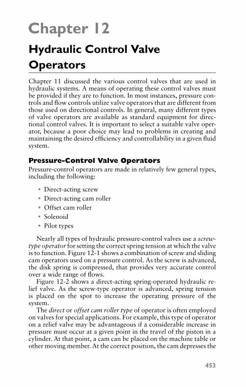
P1: FCH
GB098-12 GB098-Miller September 13, 2004 18:6 Char Count= 0
Chapter 12Hydraulic Control ValveOperatorsChapter 11 discussed the various control valves that are used inhydraulic systems. A means of operating these control valves mustbe provided if they are to function. In most instances, pressure con-trols and flow controls utilize valve operators that are different fromthose used on directional controls. In general, many different typesof valve operators are available as standard equipment for direc-tional control valves. It is important to select a suitable valve oper-ator, because a poor choice may lead to problems in creating andmaintaining the desired efficiency and controllability in a given fluidsystem.
Pressure-Control Valve OperatorsPressure-control operators are made in relatively few general types,including the following:
� Direct-acting screw� Direct-acting cam roller� Offset cam roller� Solenoid� Pilot types
Nearly all types of hydraulic pressure-control valves use a screw-type operator for setting the correct spring tension at which the valveis to function. Figure 12-1 shows a combination of screw and slidingcam operators used on a pressure control. As the screw is advanced,the disk spring is compressed, that provides very accurate controlover a wide range of flows.
Figure 12-2 shows a direct-acting spring-operated hydraulic re-lief valve. As the screw-type operator is advanced, spring tensionis placed on the spot to increase the operating pressure of thesystem.
The direct or offset cam roller type of operator is often employedon valves for special applications. For example, this type of operatoron a relief valve may be advantageous if a considerable increase inpressure must occur at a given point in the travel of the piston in acylinder. At that point, a cam can be placed on the machine table orother moving member. At the correct position, the cam depresses the
453
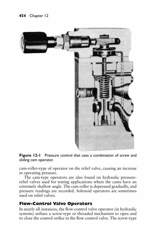
P1: FCH
GB098-12 GB098-Miller September 13, 2004 18:6 Char Count= 0
454 Chapter 12
Figure 12-1 Pressure control that uses a combination of screw andsliding cam operator.
cam-roller–type of operator on the relief valve, causing an increasein operating pressure.
The cam-type operators are also found on hydraulic pressure-relief valves used for testing applications where the cams have anextremely shallow angle. The cam roller is depressed gradually, andpressure readings are recorded. Solenoid operators are sometimesused on relief valves.
Flow-Control Valve OperatorsIn nearly all instances, the flow-control valve operator (in hydraulicsystems) utilizes a screw-type or threaded mechanism to open andto close the control orifice in the flow control valve. The screw-type
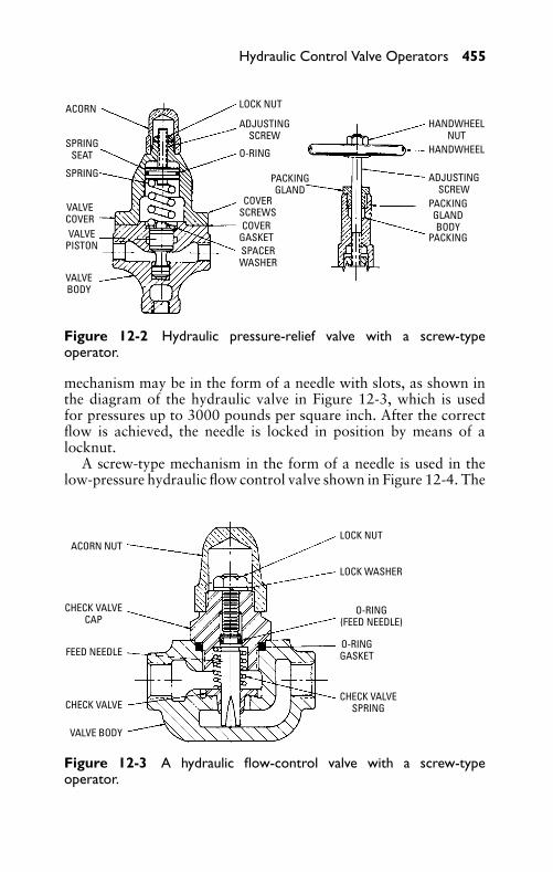
P1: FCH
GB098-12 GB098-Miller September 13, 2004 18:6 Char Count= 0
Hydraulic Control Valve Operators 455
ACORN
VALVECOVER
LOCK NUT
ADJUSTINGSCREW
PACKINGGLAND
HANDWHEELNUT
HANDWHEEL
ADJUSTINGSCREW
PACKINGGLANDBODY
PACKING
COVERSCREWSCOVER
GASKETSPACERWASHER
O-RING
VALVEPISTON
VALVEBODY
SPRING
SPRINGSEAT
Figure 12-2 Hydraulic pressure-relief valve with a screw-typeoperator.
mechanism may be in the form of a needle with slots, as shown inthe diagram of the hydraulic valve in Figure 12-3, which is usedfor pressures up to 3000 pounds per square inch. After the correctflow is achieved, the needle is locked in position by means of alocknut.
A screw-type mechanism in the form of a needle is used in thelow-pressure hydraulic flow control valve shown in Figure 12-4. The
ACORN NUT
CHECK VALVECAP
FEED NEEDLE
CHECK VALVE
VALVE BODY
LOCK NUT
LOCK WASHER
O-RING(FEED NEEDLE)
O-RINGGASKET
CHECK VALVESPRING
Figure 12-3 A hydraulic flow-control valve with a screw-typeoperator.
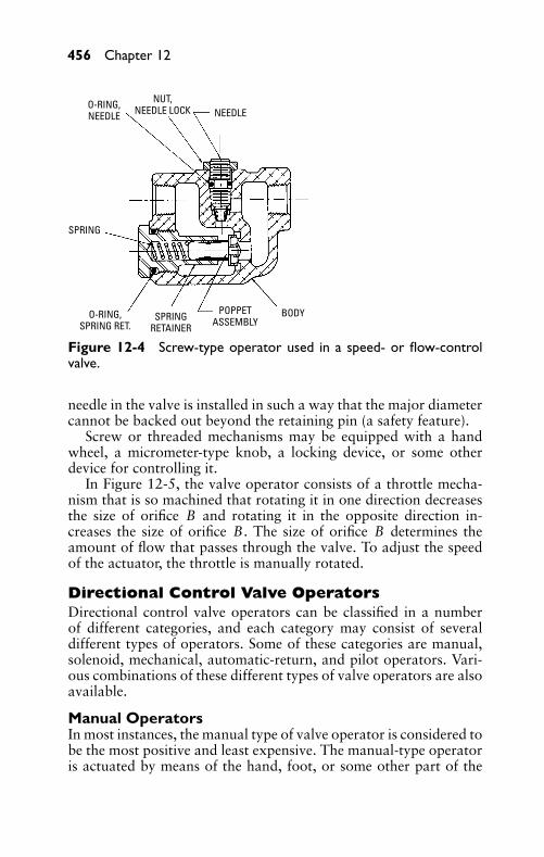
P1: FCH
GB098-12 GB098-Miller September 13, 2004 18:6 Char Count= 0
456 Chapter 12
O-RING,NEEDLE
SPRING
NUT,NEEDLE LOCK NEEDLE
O-RING,SPRING RET.
SPRINGRETAINER
POPPETASSEMBLY
BODY
Figure 12-4 Screw-type operator used in a speed- or flow-controlvalve.
needle in the valve is installed in such a way that the major diametercannot be backed out beyond the retaining pin (a safety feature).
Screw or threaded mechanisms may be equipped with a handwheel, a micrometer-type knob, a locking device, or some otherdevice for controlling it.
In Figure 12-5, the valve operator consists of a throttle mecha-nism that is so machined that rotating it in one direction decreasesthe size of orifice B and rotating it in the opposite direction in-creases the size of orifice B. The size of orifice B determines theamount of flow that passes through the valve. To adjust the speedof the actuator, the throttle is manually rotated.
Directional Control Valve OperatorsDirectional control valve operators can be classified in a numberof different categories, and each category may consist of severaldifferent types of operators. Some of these categories are manual,solenoid, mechanical, automatic-return, and pilot operators. Vari-ous combinations of these different types of valve operators are alsoavailable.
Manual OperatorsIn most instances, the manual type of valve operator is considered tobe the most positive and least expensive. The manual-type operatoris actuated by means of the hand, foot, or some other part of the
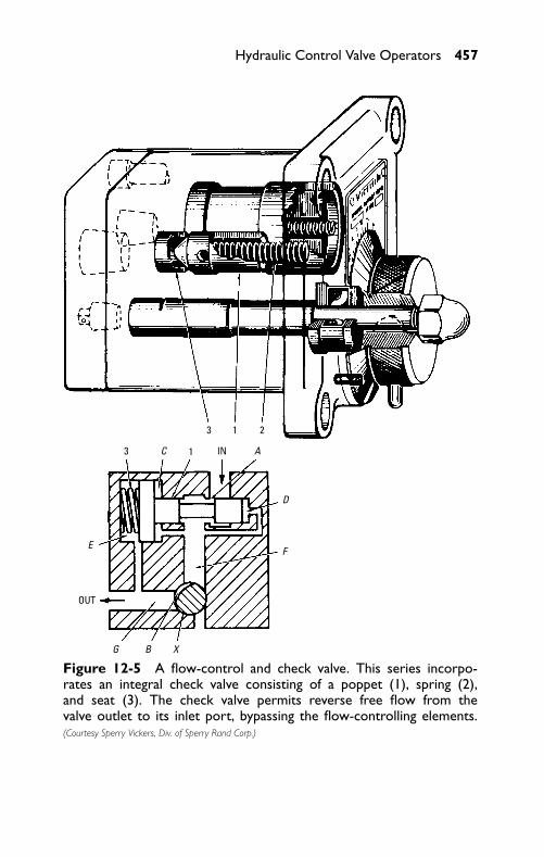
P1: FCH
GB098-12 GB098-Miller September 13, 2004 18:6 Char Count= 0
Hydraulic Control Valve Operators 457
3
3
OUT
IN A
D
X
F
BG
E
C
1
1
2
Figure 12-5 A flow-control and check valve. This series incorpo-rates an integral check valve consisting of a poppet (1), spring (2),and seat (3). The check valve permits reverse free flow from thevalve outlet to its inlet port, bypassing the flow-controlling elements.(Courtesy Sperry Vickers, Div. of Sperry Rand Corp.)
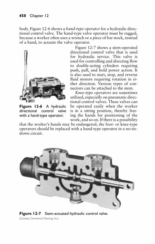
P1: FCH
GB098-12 GB098-Miller September 13, 2004 18:6 Char Count= 0
458 Chapter 12
body. Figure 12-6 shows a hand-type operator for a hydraulic direc-tional control valve. The hand-type valve operator must be rugged,because a worker often uses a wrench or a piece of bar stock, insteadof a hand, to actuate the valve operator.
Figure 12-6 A hydraulicdirectional control valvewith a hand-type operator.
Figure 12-7 shows a stem-operateddirectional control valve that is usedfor hydraulic service. This valve isused for controlling and directing flowto double-acting cylinders requiringpush, pull, and hold power action. Itis also used to start, stop, and reversefluid motors requiring rotation in ei-ther direction. Various types of con-nectors can be attached to the stem.
Knee-type operators are sometimesutilized, especially on pneumatic direc-tional control valves. These valves canbe operated easily when the workeris in a sitting position, thereby free-ing the hands for positioning of thework, and so on. If there is a possibility
that the worker’s hands may be endangered, the foot- or knee-typeoperators should be replaced with a hand-type operator in a no-tie-down circuit.
Figure 12-7 Stem-actuated hydraulic control valve.(Courtesy Commercial Shearing, Inc.)
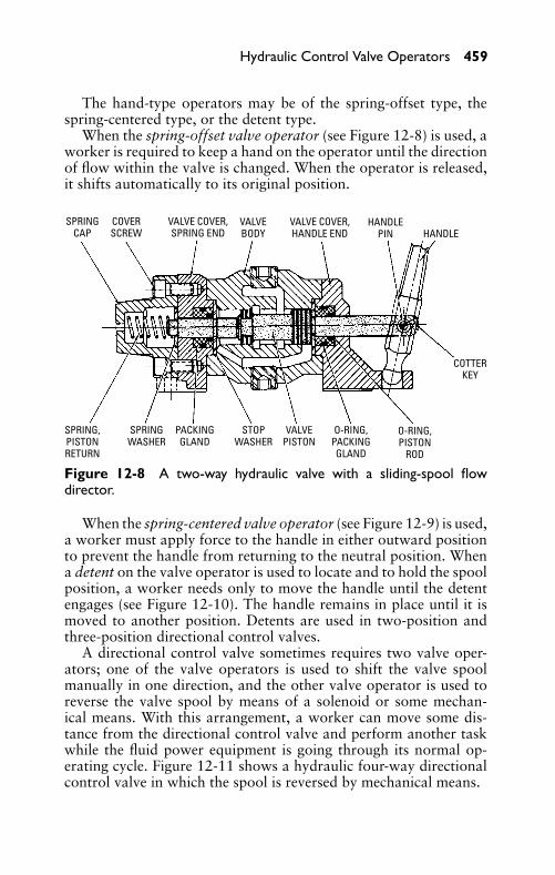
P1: FCH
GB098-12 GB098-Miller September 13, 2004 18:6 Char Count= 0
Hydraulic Control Valve Operators 459
The hand-type operators may be of the spring-offset type, thespring-centered type, or the detent type.
When the spring-offset valve operator (see Figure 12-8) is used, aworker is required to keep a hand on the operator until the directionof flow within the valve is changed. When the operator is released,it shifts automatically to its original position.
SPRINGCAP
SPRING,PISTONRETURN
SPRINGWASHER
PACKINGGLAND
STOPWASHER
VALVEPISTON
O-RING,PACKINGGLAND
O-RING,PISTON
ROD
COVERSCREW
VALVE COVER,SPRING END
VALVEBODY
VALVE COVER,HANDLE END
HANDLEPIN HANDLE
COTTERKEY
Figure 12-8 A two-way hydraulic valve with a sliding-spool flowdirector.
When the spring-centered valve operator (see Figure 12-9) is used,a worker must apply force to the handle in either outward positionto prevent the handle from returning to the neutral position. Whena detent on the valve operator is used to locate and to hold the spoolposition, a worker needs only to move the handle until the detentengages (see Figure 12-10). The handle remains in place until it ismoved to another position. Detents are used in two-position andthree-position directional control valves.
A directional control valve sometimes requires two valve oper-ators; one of the valve operators is used to shift the valve spoolmanually in one direction, and the other valve operator is used toreverse the valve spool by means of a solenoid or some mechan-ical means. With this arrangement, a worker can move some dis-tance from the directional control valve and perform another taskwhile the fluid power equipment is going through its normal op-erating cycle. Figure 12-11 shows a hydraulic four-way directionalcontrol valve in which the spool is reversed by mechanical means.
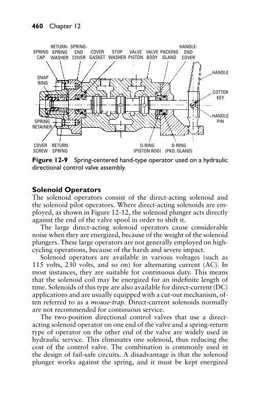
P1: FCH
GB098-12 GB098-Miller September 13, 2004 18:6 Char Count= 0
460 Chapter 12
SPRINGCAP
RETURN-SPRING
WASHER
SPRING-END
COVERCOVER
GASKETSTOP
WASHERVALVE
PISTONVALVEBODY
PACKINGGLAND
HANDLE-END
COVER
HANDLE
COTTERKEY
HANDLEPIN
O-RING(PKG. GLAND)
O-RING(PISTON ROD)
RETURNSPRING
COVERSCREW
SPRINGRETAINER
SNAPRING
Figure 12-9 Spring-centered hand-type operator used on a hydraulicdirectional control valve assembly.
Solenoid OperatorsThe solenoid operators consist of the direct-acting solenoid andthe solenoid pilot operators. Where direct-acting solenoids are em-ployed, as shown in Figure 12-12, the solenoid plunger acts directlyagainst the end of the valve spool in order to shift it.
The large direct-acting solenoid operators cause considerablenoise when they are energized, because of the weight of the solenoidplungers. These large operators are not generally employed on high-cycling operations, because of the harsh and severe impact.
Solenoid operators are available in various voltages (such as115 volts, 230 volts, and so on) for alternating current (AC). Inmost instances, they are suitable for continuous duty. This meansthat the solenoid coil may be energized for an indefinite length oftime. Solenoids of this type are also available for direct-current (DC)applications and are usually equipped with a cut-out mechanism, of-ten referred to as a mouse-trap. Direct-current solenoids normallyare not recommended for continuous service.
The two-position directional control valves that use a direct-acting solenoid operator on one end of the valve and a spring-returntype of operator on the other end of the valve are widely used inhydraulic service. This eliminates one solenoid, thus reducing thecost of the control valve. The combination is commonly used inthe design of fail-safe circuits. A disadvantage is that the solenoidplunger works against the spring, and it must be kept energized
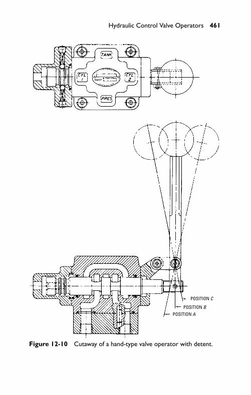
P1: FCH
GB098-12 GB098-Miller September 13, 2004 18:6 Char Count= 0
Hydraulic Control Valve Operators 461
POSITION C
POSITION BPOSITION A
Figure 12-10 Cutaway of a hand-type valve operator with detent.
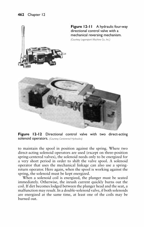
P1: FCH
GB098-12 GB098-Miller September 13, 2004 18:6 Char Count= 0
462 Chapter 12
Figure 12-11 A hydraulic four-waydirectional control valve with amechanical reversing mechanism.(Courtesy Logansport Machine Co., Inc.)
Figure 12-12 Directional control valve with two direct-actingsolenoid operators. (Courtesy Continental Hydraulics)
to maintain the spool in position against the spring. Where twodirect-acting solenoid operators are used (except on three-positionspring-centered valves), the solenoid needs only to be energized fora very short period in order to shift the valve spool. A solenoidoperator that uses the mechanical linkage can also use a spring-return operator. Here again, when the spool is working against thespring, the solenoid must be kept energized.
When a solenoid coil is energized, the plunger must be seatedimmediately. Otherwise, the inrush current quickly burns out thecoil. If dirt becomes lodged between the plunger head and the seat, amalfunction may result. In a double-solenoid valve, if both solenoidsare energized at the same time, at least one of the coils may beburned out.
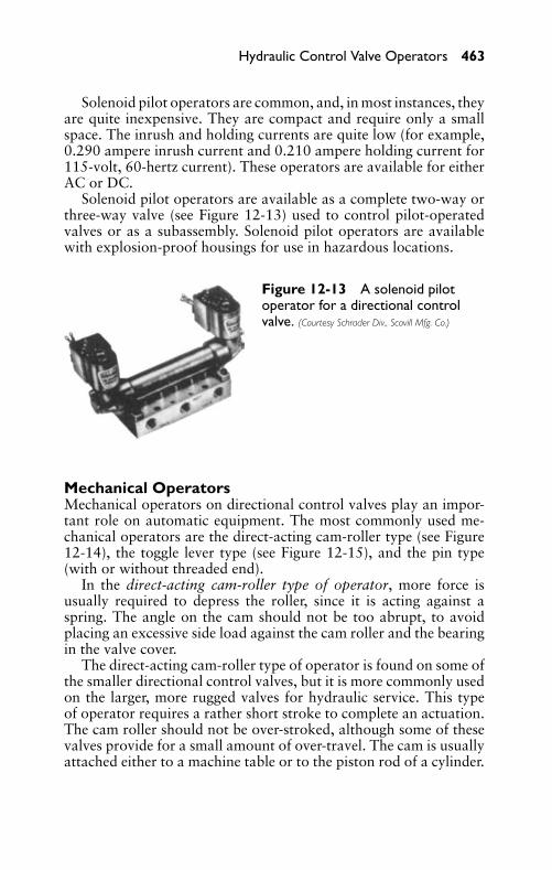
P1: FCH
GB098-12 GB098-Miller September 13, 2004 18:6 Char Count= 0
Hydraulic Control Valve Operators 463
Solenoid pilot operators are common, and, in most instances, theyare quite inexpensive. They are compact and require only a smallspace. The inrush and holding currents are quite low (for example,0.290 ampere inrush current and 0.210 ampere holding current for115-volt, 60-hertz current). These operators are available for eitherAC or DC.
Solenoid pilot operators are available as a complete two-way orthree-way valve (see Figure 12-13) used to control pilot-operatedvalves or as a subassembly. Solenoid pilot operators are availablewith explosion-proof housings for use in hazardous locations.
Figure 12-13 A solenoid pilotoperator for a directional controlvalve. (Courtesy Schrader Div., Scovill Mfg. Co.)
Mechanical OperatorsMechanical operators on directional control valves play an impor-tant role on automatic equipment. The most commonly used me-chanical operators are the direct-acting cam-roller type (see Figure12-14), the toggle lever type (see Figure 12-15), and the pin type(with or without threaded end).
In the direct-acting cam-roller type of operator, more force isusually required to depress the roller, since it is acting against aspring. The angle on the cam should not be too abrupt, to avoidplacing an excessive side load against the cam roller and the bearingin the valve cover.
The direct-acting cam-roller type of operator is found on some ofthe smaller directional control valves, but it is more commonly usedon the larger, more rugged valves for hydraulic service. This typeof operator requires a rather short stroke to complete an actuation.The cam roller should not be over-stroked, although some of thesevalves provide for a small amount of over-travel. The cam is usuallyattached either to a machine table or to the piston rod of a cylinder.
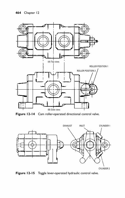
P1: FCH
GB098-12 GB098-Miller September 13, 2004 18:6 Char Count= 0
464 Chapter 12
(A) Top view.
(B) Side view.
ROLLER POSITION 1
ROLLER POSITION 2
Figure 12-14 Cam roller-operated directional control valve.
EXHAUST INLET CYLINDER 1
CYLINDER 2
Figure 12-15 Toggle lever-operated hydraulic control valve.
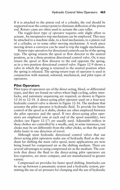
P1: FCH
GB098-12 GB098-Miller September 13, 2004 18:6 Char Count= 0
Hydraulic Control Valve Operators 465
If it is attached to the piston rod of a cylinder, the rod should besupported near the contact point to eliminate deflection of the pistonrod. Rotary cams are often used to actuate the cam roller.
The toggle-lever type of operator requires only slight effort toactuate. An inexpensive trip mechanism can be employed. This maybe attached to a machine slide, to a feed mechanism, to a piston rodof a cylinder, or to some other moving mechanism. A work piecemoving down a conveyor can be used to trip the toggle mechanism.
Return-type operators for directional controls can be of the springtype. The spring returns the spool or flow director to the neutralposition, as in a three-position directional control valve. Or, it mayreturn the spool or flow director to the end opposite the spring,as in a two-position directional control valve. Figure 12-9 shows avalve in which the spring is returned to the neutral position whenthe spring is released. The spring-return type of operator is used inconjunction with manual, solenoid, mechanical, and pilot types ofoperators.
Pilot OperatorsPilot types of operators are of the direct acting, bleed, or differentialtypes, and they are found on valves where high cycling, safety inter-locks, and automatic sequencing are required, as shown in Figures12-16 to 12-18. A direct-acting pilot operator used on a four-wayhydraulic control valve is shown in Figure 12-16. The medium thatactuates the pilot operator is hydraulic fluid. To provide for bettercontrol of the spool as it shifts, chokes are often employed betweenthe pilot operator and the spool. If two direct-acting pilot oper-ators are employed (one at each end of the spool assembly), twochokes (see Figure 12-17) are usually used. Adjustable orifices inthese chokes are controlled by a needle, and, in some instances, onechoke may be set differently from the other choke, so that the spoolshifts faster in one direction of travel.
Although most hydraulic directional control valves that usedirect-acting pilot operators make use of hydraulic fluid as the me-dium for shifting the main valve spool, more applications are nowbeing found for compressed air as the shifting medium. There areseveral advantages to using compressed air as the medium. The con-trols that direct the fluid to the direct-acting pilot operators areless expensive, are more compact, and are manufactured in greatervariety.
Compressed air provides for faster spool shifting. Interlocks canbe set up between a pneumatic system and a hydraulic system, per-mitting the use of air pressure for clamping and the use of hydraulic
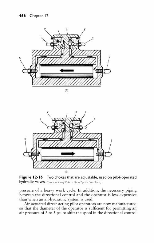
P1: FCH
GB098-12 GB098-Miller September 13, 2004 18:6 Char Count= 0
466 Chapter 12
X
X 3
3
2
2
6
6
5
5
1
1
Y
Y
(A)
(B)
Figure 12-16 Two chokes that are adjustable, used on pilot-operatedhydraulic valves. (Courtesy Sperry Vickers, Div. of Sperry Rand Corp.)
pressure of a heavy work cycle. In addition, the necessary pipingbetween the directional control and the operator is less expensivethan when an all-hydraulic system is used.
Air-actuated direct-acting pilot operators are now manufacturedso that the diameter of the operator is sufficient for permitting anair pressure of 3 to 5 psi to shift the spool in the directional control
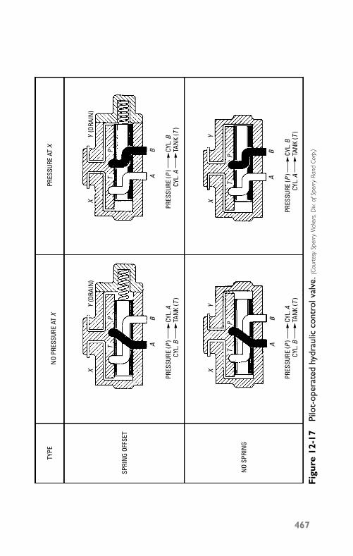
P1: FCH
GB098-12 GB098-Miller September 13, 2004 18:6 Char Count= 0
TP
TP
TP
TP
TYPE
SPRI
NG
OFFS
ET
NO
SPRI
NG
NO
PRES
SURE
AT
X P
RESS
URE
AT X
PRES
SURE
(P)
CYL.
ACY
L. B
TAN
K (T
)
PRES
SURE
(P)
CYL.
ACY
L. B
TAN
K (T
)
PRES
SURE
(P)
CYL.
BCY
L. A
TAN
K (T
)
PRES
SURE
(P)
CYL.
BCY
L. A
TAN
K (T
)
A
XY
XY
XY
XY
BA
B
AB
AB
(DRA
IN)
(DRA
IN)
Fig
ure
12-1
7Pi
lot-
oper
ated
hydr
aulic
cont
rolv
alve
. (Co
urte
sySp
erry
Vick
ers,
Div.
ofSp
erry
Rand
Corp
.)
467
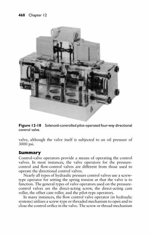
P1: FCH
GB098-12 GB098-Miller September 13, 2004 18:6 Char Count= 0
468 Chapter 12
Figure 12-18 Solenoid-controlled pilot-operated four-way directionalcontrol valve.
valve, although the valve itself is subjected to an oil pressure of3000 psi.
SummaryControl-valve operators provide a means of operating the controlvalves. In most instances, the valve operators for the pressure-control and flow-control valves are different from those used tooperate the directional control valves.
Nearly all types of hydraulic pressure control valves use a screw-type operator for setting the spring tension at that the valve is tofunction. The general types of valve operators used on the pressure-control valves are the direct-acting screw, the direct-acting camroller, the offset cam roller, and the pilot-type operators.
In many instances, the flow control valve operator (in hydraulicsystems) utilizes a screw-type or threaded mechanism to open and toclose the control orifice in the valve. The screw or thread mechanism
P1: FCH
GB098-12 GB098-Miller September 13, 2004 18:6 Char Count= 0
Hydraulic Control Valve Operators 469
may be equipped with a handwheel, a micrometer-type knob, a lock-ing device, or some other device for controlling it.
Several different types of operators are used for the directionalcontrol valves. They are classified as manual, solenoid, mechani-cal, automatic-return, and pilot operators. Various combinations ofthese types of valve operators are also available.
Review Questions1. What is the purpose of the valve operator?2. List three types of pressure control-valve operators.3. What types of operators are used for flow-control valves?4. List four types of directional control valves.5. What applications are most suitable for pilot-operated direc-
tional control valves?6. Name two applications for solenoid-actuated relief valves.7. Name three applications for cam-operated relief valves.8. What type of actuator should be used on directional control
for high-cycling operations?9. What are the differences between AC and DC solenoids?
10. What is the most commonly used type of pressure-controlvalve operator for setting spring tension?
11. What type of valve operator is considered to be the most pos-itive and least expensive?
12. What are three kinds of hand-type operators?13. Where is the knee-type operator utilized?14. What type of solenoid is not recommended for continuous
service?15. What is the difference between inrush current and holding
current in a solenoid?16. What are the most commonly used mechanical operators?17. List two types of pilot operators.18. What type of operator do nearly all types of hydraulic pressure
control valves use?19. How are operators for directional valves classified?

P1: FCH
GB098-12 GB098-Miller September 13, 2004 18:6 Char Count= 0
470
P1: FCH
GB098-13 GB098-Miller September 13, 2004 18:7 Char Count= 0
Part IV
Fluids, Lines, andFittings
471

P1: FCH
GB098-13 GB098-Miller September 13, 2004 18:7 Char Count= 0
472
P1: FCH
GB098-13 GB098-Miller September 13, 2004 18:7 Char Count= 0
Chapter 13Hydraulic FluidsIn hydraulics, hydraulic fluids are usually divided into three cate-gories: petroleum-base fluids, synthetic-base fluids, and water. Thefirst two fluids are used in so-called packaged-power devices. Wateris generally used as the hydraulic fluid in central hydraulic systems.
The function of a good hydraulic fluid is threefold:
� It is a means of transmission of fluid power.� It is a means of lubrication of the components of the fluid
power system.� It acts as a sealant.
The selection of the proper hydraulic fluid is important, becauseit has a direct bearing on the efficiency of the hydraulic system,on the cost of maintenance, and on the service life of the system’scomponents.
Petroleum-Base FluidsThree basic types of mineral oils are used:
� Pennsylvania, or paraffin-base oils.� Gulf coast, or naphthenic- and asphaltic-base oils.� Mid-Continent, or mixed-base oils.
These contain both naphthenic and paraffin compounds.To obtain certain characteristics, chemicals are added to oil.
These chemicals are called additives. Additives cannot make an in-ferior oil perform as well as good oil, but they can make a good oilperform even better. An additive may be in the form of an antifoamagent, a rust inhibitor, a film-strengthening agent, or an oxidationstabilizer.
You should not attempt to place additives in hydraulic oil. Thatjob is primarily for the oil manufacturer or refiner.
Synthetic-Base FluidsSince fire hazards are prevalent around certain types of hydrauli-cally operated machines (especially where open fires are present),much research has been done to develop fire-resistant hydraulic flu-ids. These fluids are divided into two classifications: synthetic-basemixtures and water-base fluids. Not all synthetic-base fluids are fire-resistant.
473
P1: FCH
GB098-13 GB098-Miller September 13, 2004 18:7 Char Count= 0
474 Chapter 13
Synthetic-base fluids include chemical compounds (such as thechlorinated biphenyls, phosphate esters, or mixtures containingeach). These hydraulic fluids are fire-resistant because a large per-centage of phosphorous and chloride materials are included.
Water-base fluids depend on a high percentage of water to im-prove the fire-resistant nature of the fluid. In addition to water, thesecompounds contain antifreeze materials (such as glycol-type thick-eners, inhibitor, and additives).
Synthetic-base fluids have both advantages and disadvantages.Following are some of the advantages:
� Many of them are fire-resistant.� Sludge or petroleum-gum formation is reduced.� Temperature has little effect on the thickening or thinning or
the fluid.
A disadvantage of many synthetic fluids is their deteriorating ef-fect on some materials (such as packing, paints, and some metalsused in intake filters).
Quality RequirementsCertain qualifications are demanded of good hydraulic oil. The oilshould not break down and it should give satisfactory service. High-quality hydraulic oils have many of the following properties:
� Prevent rusting of the internal parts of valves, pump, and cylin-ders.
� Prevent formation of a sludge or gum that can clog small pas-sages in the valves and screens in filters.
� Reduce foaming action that may cause activation in the pump.� Provide a long service lives.� Retain their original properties through hard usage (must not
deteriorate chemically).� Resist changing the flow ability or viscosity as the temperature
changes.� Form a protective film that resists wear of working parts.� Prevent pitting action on the parts of pumps, valves, and cylin-
ders.� Do not emulsify with the water. Water is often present in the
system either from external sources or from condensation.� Have no deteriorating effect on gaskets and packing.
P1: FCH
GB098-13 GB098-Miller September 13, 2004 18:7 Char Count= 0
Hydraulic Fluids 475
MaintenanceProper maintenance of hydraulic oil is often forgotten. Too often,hydraulic oil is treated in a matter-of-fact manner. Following are afew simple rules regarding maintenance:
� Store oil in clean container. The container should not containlint or dirt.
� Keep lids or covers tight on the oil containers, so that dirt ordust cannot settle on the surface of the oil. Oil should neverbe stored in open containers.
� Store oil in a dry place. Do not allow it to be exposed to rainor snow.
� Do not mix different types of hydraulic oils. Oils having dif-ferent properties may cause trouble when mixed.
� Use a recommended hydraulic fluid for the pump.� Use clean containers for transporting oil from the storage tank
to the reservoir.� Ensure that the system is clean before changing oil in the power
unit. Do not add clean oil to dirty oil.� Check the oil in the power unit regularly. Have the oil supplier
check the sample of the oil from the power unit in the labora-tory. Contaminants often cause trouble. These can be detectedby frequent tests, which may aid in determining the source ofcontamination. On machines that use coolants or cutting oil,extreme caution should be exercised to keep these fluids fromentering the hydraulic system and contaminating the oil.
� Drain the oil in the system at regular intervals. It is difficultto set a hard-and-fast rule as to the length of the interval. Insome instances, it may be necessary to drain the oil only everytwo years. However, once each month may be necessary forother operating conditions. This depends on the conditionsof operation and on the original quality of the hydraulic oil.Thus, several factors should be considered in determining thelength of the interval.
Before placing new oil in the hydraulic system, it is often recom-mended that the system be cleaned with a hydraulic system cleaner.The cleaner is placed in the system after the oil has been removed.The hydraulic system cleaner should be used while the hydraulic sys-tem is in operation, and usually requires 50 to 100 hours to cleanthe system. Then, the cleaner should be drained; the filters, strainers,
P1: FCH
GB098-13 GB098-Miller September 13, 2004 18:7 Char Count= 0
476 Chapter 13
and oil reservoir cleaned; and the system filled with good hydraulicoil.
If the hydraulic oil is spilled on the floor in either changing oradding oil to the system, it should be cleaned up at once. Goodhousekeeping procedure is important in reducing fire and othersafety hazards.
Change of Fluids in a Hydraulic SystemIf the fluid in a hydraulic system is to be changed from a petroleum-base fluid to a fire-resistant fluid or vice versa, the system should bedrained and cleaned completely.
Keep in mind the following when changing from a petroleum-base fluid to a water-base fluid:
� Drain out all the oil (or at least as much as possible) and cleanthe system.
� Either remove lines that form pockets, or force the oil out witha blast of clean, dry air.
� Strainers should be cleaned thoroughly. Filters should becleaned thoroughly and the filter element replaced.
� Check the internal paint in all components. It is likely that thepaint should be removed.
� Check the gaskets and packing. Those that contain either corkor asbestos may cause trouble.
� Flush out the system. Either a water-base fluid or a good flush-ing solution is recommended.
� Since hydraulic fluids are expensive, the system should be freeof external leaks.
Keep in mind the following when changing from a water-basefluid to a petroleum-base fluid:
� Remove all of the water-base fluid. This step is very important.A small quantity of water-base fluid left in the system can causeconsiderable trouble with the new petroleum-base fluid.
� The reservoir should be scrubbed and cleaned thoroughly. Ifthe interior of the reservoir is not painted, it should be coatedwith a good sealer that is not affected by hydraulic oil.
� The components should be dismantled and cleaned thor-oughly. Cleaning with steam is effective.
� Flush the system with hydraulic oil and then drain.� Fill the system with good hydraulic oil.
P1: FCH
GB098-13 GB098-Miller September 13, 2004 18:7 Char Count= 0
Hydraulic Fluids 477
A similar procedure should be used in changing from synthetic-base fluids to petroleum-base fluids—and vice versa. If phosphate-base fluids are used, the packing should be changed. If satisfactoryperformance from a hydraulic fluid and a hydraulic system is ex-pected, use a good grade of hydraulic fluid, keep it clean, change atregular intervals, do not allow it to become overheated, and keepcontaminants out of the system.
Selection of a Hydraulic FluidThe main functions of the hydraulic fluid are to transmit a forceapplied to one point in the fluid system to some other point in thesystem, and to reproduce quickly any variation in the applied force.Thus, the fluid should flow readily, and it should be relatively in-compressible. The choice of the most satisfactory hydraulic fluid foran industrial application involves two distinct considerations:
� Fluid for each system should have certain essential physicalproperties and characteristics of flow and performance.
� The fluid should have desirable performance characteristicsover a period. The oil may be suitable when initially installed.However, its characteristics or properties may change, result-ing in an adverse effect on the performance of the hydraulicsystem.
The hydraulic fluid should provide a suitable seal or film betweenmoving parts to reduce friction. It is desirable that the fluid shouldnot produce adverse physical or chemical changes while in the hy-draulic system. The fluid should not promote rusting or corrosion inthe system, and it should act as a suitable lubricant to provide filmstrength for separating the moving parts, to minimize wear betweenthem.
Certain terms are required to evaluate the performance and suit-ability of a hydraulic fluid. Important items are discussed in thefollowing sections.
Specific WeightThe term specific weight of a liquid indicates the weight per unitof volume. For example, water at 60◦F weighs 62.4 pounds percubic foot. The specific gravity of a given liquid is defined as theratio of the specific weight of the given liquid divided by the specificweight of water. For example, if the specific gravity of the oil is 0.93,the specific weight of the oil is approximately 58 pounds per cubicfoot (0.93 × 62.4). For commercially available hydraulic fluids, thespecific gravity may range from 0.80 to 1.45.
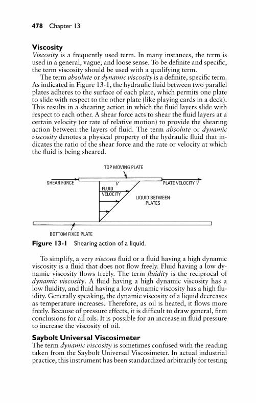
P1: FCH
GB098-13 GB098-Miller September 13, 2004 18:7 Char Count= 0
478 Chapter 13
ViscosityViscosity is a frequently used term. In many instances, the term isused in a general, vague, and loose sense. To be definite and specific,the term viscosity should be used with a qualifying term.
The term absolute or dynamic viscosity is a definite, specific term.As indicated in Figure 13-1, the hydraulic fluid between two parallelplates adheres to the surface of each plate, which permits one plateto slide with respect to the other plate (like playing cards in a deck).This results in a shearing action in which the fluid layers slide withrespect to each other. A shear force acts to shear the fluid layers at acertain velocity (or rate of relative motion) to provide the shearingaction between the layers of fluid. The term absolute or dynamicviscosity denotes a physical property of the hydraulic fluid that in-dicates the ratio of the shear force and the rate or velocity at whichthe fluid is being sheared.
TOP MOVING PLATE
FLUIDVELOCITY
V
BOTTOM FIXED PLATE
PLATE VELOCITY V
LIQUID BETWEENPLATES
SHEAR FORCE
Figure 13-1 Shearing action of a liquid.
To simplify, a very viscous fluid or a fluid having a high dynamicviscosity is a fluid that does not flow freely. Fluid having a low dy-namic viscosity flows freely. The term fluidity is the reciprocal ofdynamic viscosity. A fluid having a high dynamic viscosity has alow fluidity, and fluid having a low dynamic viscosity has a high flu-idity. Generally speaking, the dynamic viscosity of a liquid decreasesas temperature increases. Therefore, as oil is heated, it flows morefreely. Because of pressure effects, it is difficult to draw general, firmconclusions for all oils. It is possible for an increase in fluid pressureto increase the viscosity of oil.
Saybolt Universal ViscosimeterThe term dynamic viscosity is sometimes confused with the readingtaken from the Saybolt Universal Viscosimeter. In actual industrialpractice, this instrument has been standardized arbitrarily for testing
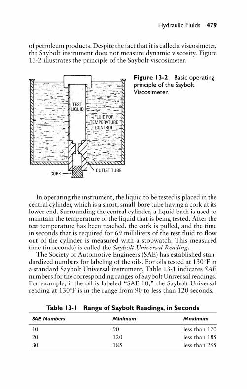
P1: FCH
GB098-13 GB098-Miller September 13, 2004 18:7 Char Count= 0
Hydraulic Fluids 479
of petroleum products. Despite the fact that it is called a viscosimeter,the Saybolt instrument does not measure dynamic viscosity. Figure13-2 illustrates the principle of the Saybolt viscosimeter.
CORKOUTLET TUBE
TESTLIQUID
FLUID FORTEMPERATURE
CONTROL
Figure 13-2 Basic operatingprinciple of the SayboltViscosimeter.
In operating the instrument, the liquid to be tested is placed in thecentral cylinder, which is a short, small-bore tube having a cork at itslower end. Surrounding the central cylinder, a liquid bath is used tomaintain the temperature of the liquid that is being tested. After thetest temperature has been reached, the cork is pulled, and the timein seconds that is required for 69 milliliters of the test fluid to flowout of the cylinder is measured with a stopwatch. This measuredtime (in seconds) is called the Saybolt Universal Reading.
The Society of Automotive Engineers (SAE) has established stan-dardized numbers for labeling of the oils. For oils tested at 130◦F ina standard Saybolt Universal instrument, Table 13-1 indicates SAEnumbers for the corresponding ranges of Saybolt Universal readings.For example, if the oil is labeled “SAE 10,” the Saybolt Universalreading at 130◦F is in the range from 90 to less than 120 seconds.
Table 13-1 Range of Saybolt Readings, in Seconds
SAE Numbers Minimum Maximum
10 90 less than 12020 120 less than 18530 185 less than 255
P1: FCH
GB098-13 GB098-Miller September 13, 2004 18:7 Char Count= 0
480 Chapter 13
Viscosity ProblemsIf the viscosity of the hydraulic fluid is too high (fluid does not flowas freely as desired), the following undesirable actions may result:
� Internal resistance, or fluid friction, is high, which means ahigh resistance to flow through the valves and pumps.
� Power consumption is high, because fluid friction is high.� Fluid temperature is high, because friction is high.� Pressure drop through the system may be higher than desired,
which means that less useful pressure is available for doinguseful work.
� The motion and operation of the various parts may be slowand sluggish. This is a result of the high fluid resistance.
If the viscosity of the hydraulic fluid is too low (fluid flows morefreely than desired), the following undesirable actions may result:
� More leakage may occur in the clearance space than is desired.� A lower pressure than is desired may occur in the system.� An increase in wear may occur because of the lack of a strong
fluid film between mechanical parts that move in relation toeach other.
� Pump leakage may increase, resulting in reduced pump deliv-ery and efficiency.
� A loss of control may occur because fluid film strength is re-duced.
With respect to Saybolt readings, the viscosimeter readings of oilsin service should not exceed 4000 seconds, and they should not readless than 45 seconds.
Viscosity IndexIdeally, the dynamic viscosity of any oil should change only slightlyas the temperature changes. In the automobile engine, the oil in thecrankcase is operated over a wide range of temperatures. On a verycold winter morning, until the car has been operated for some lengthof time, the temperature of the oil may be very low, and the dynamicviscosity of the oil may be very high. If the dynamic viscosity of theoil is excessively high, large forces and large amounts of power maybe required to shear the oil films. Also, after the engine has beenoperated for a period of time on a hot summer day, the temperatureof the oil may be very high, and the dynamic viscosity of the oil maybe too low. Therefore, the oil may not form a suitable lubricatingfilm between the sliding surfaces. A breakdown of the oil film may

P1: FCH
GB098-13 GB098-Miller September 13, 2004 18:7 Char Count= 0
Hydraulic Fluids 481
result in excessive wear of the metal surfaces and a loss of power inthe engine.
The term viscosity index is an arbitrarily defined ratio. It indi-cates the relative change in Saybolt Universal reading, with respectto temperature. The most desirable oils are those that have a high vis-cosity index (that is, the change in Saybolt reading is relatively smallas the temperature changes). Oils having a small viscosity index reg-ister a relatively large change in Saybolt reading as the temperaturechanges.
Lubricating ValueThe terms oiliness and lubricity are used to refer to the lubricatingvalue of any oil. These terms are most often used when the movingsurfaces are relatively close and may make metal-to-metal contact.At the same pressure and temperature, oil A may be a better lubri-cant than another oil B. Therefore, oil A possesses more oiliness orlubricity than oil B. The lubricating value of a fluid depends on itschemical structure and its reaction with various metal surfaces whenthe metal surfaces are relatively close to each other. Thus, oilinessand lubricity are extremely important in the performance of the oil.
Pour PointThe pour point of a fluid is defined as the lowest temperature atwhich the fluid flows when it is chilled under given conditions. Thepour point is important when the hydraulic system is exposed tolow temperatures. As a general rule, the most desirable pour pointshould be approximately 20◦F below the lowest temperature to thatthe fluid will be exposed.
Oxidation and ContaminationOxidation is a chemical reaction in which oxygen combines withanother element. Because air contains oxygen, the oxygen that isinvolved in fluid oxidation comes from exposing or mixing the fluidwith air. The oxidation reaction increases with increased exposureof the oil to the air.
Undesirable quantities of air in hydraulic systems can be causedby mechanical factors, such as air leakage into the oil suction line,low fluid level in the oil reservoir, and leakage around the packing.Air leakage may result in the erratic motion of mechanical parts,and it may cause the fluid to oxidize more rapidly. All oils containsome air in solution that may not cause any trouble. If the air is notin solution, a foaming action may result. If trapped in a cylinder, airthat is not in solution is highly compressible. However, oil is not ashighly compressible as air. Irregular action of a cylinder, for example,may result if a significant quantity of air becomes undissolved.
P1: FCH
GB098-13 GB098-Miller September 13, 2004 18:7 Char Count= 0
482 Chapter 13
Ferrous metals are destroyed by rust. Rust can develop in a hy-draulic system if moisture is present. This moisture may be the resultof condensation from air that enters through leaks on the intake (lowpressure) side of a pump.
The oxidation stability of any oil refers to the inherent ability ofoil to resist oxidation. Oxidation increases with increases in tem-perature, pressure, and agitation. Oxidation also increases as the oilbecomes contaminated with such substances as grease, dirt, mois-ture, paint, and joint compound. Various metals also promote oiloxidation, and the various fluids have different oxidation character-istics. Table 13-2 lists the essential properties of the commerciallyavailable hydraulic fluids.
Table 13-2 Properties of Available Hydraulic Fluids
Petroleum-Base FluidsViscosity range, Saybolt Universal reading, in seconds,at 100◦F
40 to 5000
Operating temperature, in ◦F –75 to 500Minimum viscosity index 76 to 225Fire-Resistant Fluids (water-oil emulsions, water-glycol, phosphate-ester, chlorinated hydrocarbon, sili-cate ester, silicon)Viscosity range, Saybolt Universal reading, in seconds,at 100◦F
20 to 5000
Operating temperature, in ◦F –100 to 600
Hydraulic FiltersHydraulic filters are needed to aid in eliminating many of the po-tential causes of hydraulic system failures. Proper filters and properfilter maintenance are important in obtaining satisfactory results ina hydraulic system.
Although most hydraulic systems are considered closed, they arenot free from contaminants. Following are four sources of contam-inants common in hydraulic systems:
� Wear—As the sliding members of components move, smallparticles of metal and seals enter the fluid. A typical exampleof this action is the movement of a cast-iron piston withina steel cylinder tube. Wear begins as soon as the cylinder isplaced in operation, although it may not be visible to the eyefor a long period.
� Formation of sludge and acids due to fluid breakdown—Whenextreme heat and pressure are encountered, chemical reaction
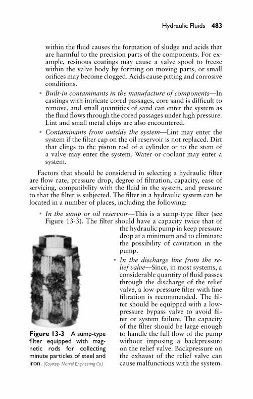
P1: FCH
GB098-13 GB098-Miller September 13, 2004 18:7 Char Count= 0
Hydraulic Fluids 483
within the fluid causes the formation of sludge and acids thatare harmful to the precision parts of the components. For ex-ample, resinous coatings may cause a valve spool to freezewithin the valve body by forming on moving parts, or smallorifices may become clogged. Acids cause pitting and corrosiveconditions.
� Built-in contaminants in the manufacture of components—Incastings with intricate cored passages, core sand is difficult toremove, and small quantities of sand can enter the system asthe fluid flows through the cored passages under high pressure.Lint and small metal chips are also encountered.
� Contaminants from outside the system—Lint may enter thesystem if the filter cap on the oil reservoir is not replaced. Dirtthat clings to the piston rod of a cylinder or to the stem ofa valve may enter the system. Water or coolant may enter asystem.
Factors that should be considered in selecting a hydraulic filterare flow rate, pressure drop, degree of filtration, capacity, ease ofservicing, compatibility with the fluid in the system, and pressureto that the filter is subjected. The filter in a hydraulic system can belocated in a number of places, including the following:
� In the sump or oil reservoir—This is a sump-type filter (seeFigure 13-3). The filter should have a capacity twice that of
Figure 13-3 A sump-typefilter equipped with mag-netic rods for collectingminute particles of steel andiron. (Courtesy Marvel Engineering Co.)
the hydraulic pump in keep pressuredrop at a minimum and to eliminatethe possibility of cavitation in thepump.
� In the discharge line from the re-lief valve—Since, in most systems, aconsiderable quantity of fluid passesthrough the discharge of the reliefvalve, a low-pressure filter with finefiltration is recommended. The fil-ter should be equipped with a low-pressure bypass valve to avoid fil-ter or system failure. The capacityof the filter should be large enoughto handle the full flow of the pumpwithout imposing a backpressureon the relief valve. Backpressure onthe exhaust of the relief valve cancause malfunctions with the system.
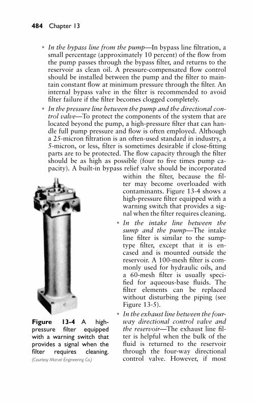
P1: FCH
GB098-13 GB098-Miller September 13, 2004 18:7 Char Count= 0
484 Chapter 13
� In the bypass line from the pump—In bypass line filtration, asmall percentage (approximately 10 percent) of the flow fromthe pump passes through the bypass filter, and returns to thereservoir as clean oil. A pressure-compensated flow controlshould be installed between the pump and the filter to main-tain constant flow at minimum pressure through the filter. Aninternal bypass valve in the filter is recommended to avoidfilter failure if the filter becomes clogged completely.
� In the pressure line between the pump and the directional con-trol valve—To protect the components of the system that arelocated beyond the pump, a high-pressure filter that can han-dle full pump pressure and flow is often employed. Althougha 25-micron filtration is an often-used standard in industry, a5-micron, or less, filter is sometimes desirable if close-fittingparts are to be protected. The flow capacity through the filtershould be as high as possible (four to five times pump ca-pacity). A built-in bypass relief valve should be incorporated
Figure 13-4 A high-pressure filter equippedwith a warning switch thatprovides a signal when thefilter requires cleaning.(Courtesy Marvel Engineering Co.)
within the filter, because the fil-ter may become overloaded withcontaminants. Figure 13-4 shows ahigh-pressure filter equipped with awarning switch that provides a sig-nal when the filter requires cleaning.
� In the intake line between thesump and the pump—The intakeline filter is similar to the sump-type filter, except that it is en-cased and is mounted outside thereservoir. A 100-mesh filter is com-monly used for hydraulic oils, anda 60-mesh filter is usually speci-fied for aqueous-base fluids. Thefilter elements can be replacedwithout disturbing the piping (seeFigure 13-5).
� In the exhaust line between the four-way directional control valve andthe reservoir—The exhaust line fil-ter is helpful when the bulk of thefluid is returned to the reservoirthrough the four-way directionalcontrol valve. However, if most
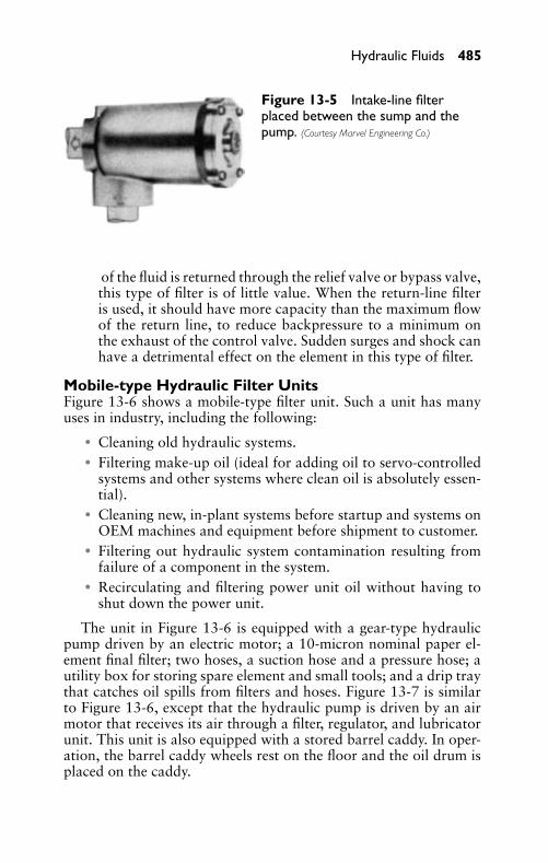
P1: FCH
GB098-13 GB098-Miller September 13, 2004 18:7 Char Count= 0
Hydraulic Fluids 485
Figure 13-5 Intake-line filterplaced between the sump and thepump. (Courtesy Marvel Engineering Co.)
of the fluid is returned through the relief valve or bypass valve,this type of filter is of little value. When the return-line filteris used, it should have more capacity than the maximum flowof the return line, to reduce backpressure to a minimum onthe exhaust of the control valve. Sudden surges and shock canhave a detrimental effect on the element in this type of filter.
Mobile-type Hydraulic Filter UnitsFigure 13-6 shows a mobile-type filter unit. Such a unit has manyuses in industry, including the following:
� Cleaning old hydraulic systems.� Filtering make-up oil (ideal for adding oil to servo-controlled
systems and other systems where clean oil is absolutely essen-tial).
� Cleaning new, in-plant systems before startup and systems onOEM machines and equipment before shipment to customer.
� Filtering out hydraulic system contamination resulting fromfailure of a component in the system.
� Recirculating and filtering power unit oil without having toshut down the power unit.
The unit in Figure 13-6 is equipped with a gear-type hydraulicpump driven by an electric motor; a 10-micron nominal paper el-ement final filter; two hoses, a suction hose and a pressure hose; autility box for storing spare element and small tools; and a drip traythat catches oil spills from filters and hoses. Figure 13-7 is similarto Figure 13-6, except that the hydraulic pump is driven by an airmotor that receives its air through a filter, regulator, and lubricatorunit. This unit is also equipped with a stored barrel caddy. In oper-ation, the barrel caddy wheels rest on the floor and the oil drum isplaced on the caddy.
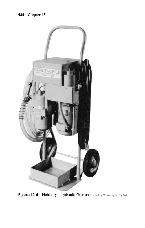
P1: FCH
GB098-13 GB098-Miller September 13, 2004 18:7 Char Count= 0
486 Chapter 13
Figure 13-6 Mobile-type hydraulic filter unit. (Courtesy Marvel Engineering Co.)
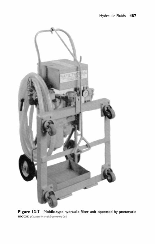
P1: FCH
GB098-13 GB098-Miller September 13, 2004 18:7 Char Count= 0
Hydraulic Fluids 487
Figure 13-7 Mobile-type hydraulic filter unit operated by pneumaticmotor. (Courtesy Marvel Engineering Co.)
P1: FCH
GB098-13 GB098-Miller September 13, 2004 18:7 Char Count= 0
488 Chapter 13
SummaryHydraulic fluids are usually divided into three categories: petroleum-base fluids, synthetic-base fluids, and water. The function of a goodhydraulic fluid is threefold: it is a means of transmitting fluid power;it is a means of lubricating the components of a fluid power system;and it acts as a sealant.
To obtain certain desired characteristics, chemicals called addi-tives are added to any oil. An additive may be in the form of anantifoam agent, a rust inhibitor, a film-strengthening agent, or anoxidation stabilizer.
The main functions of a hydraulic fluid are to transmit a force ap-plied at one point in a system to some other point in the system, andto reproduce quickly any variation in the applied force. Thus, thefluid should flow readily, and it should be relatively incompressible.The choice of the most satisfactory hydraulic fluid for an industrialapplication involves two distinct considerations: the fluid shouldhave certain essential physical properties and characteristics of flowand performance; and the fluid should have desirable performancecharacteristics over a period.
A very viscous fluid or a fluid having a high dynamic viscosityis a fluid that does not flow freely; a fluid having a low dynamicviscosity flows freely. The term fluidity is the reciprocal of dynamicviscosity. A fluid having a high dynamic viscosity has a low fluidity,and a fluid having a low dynamic viscosity has a high fluidity.
The terms oiliness and lubricity refer to the lubricating value ofany oil. The lubricating value of a fluid depends on its chemicalstructure and its reaction with various metal surfaces when the sur-faces are relatively close to each other.
Hydraulic filters are needed to aid in eliminating many of thepotential causes of failure in hydraulic systems. Proper filters andproper filter maintenance are important factors in obtaining satis-factory results in a hydraulic system. In selecting a hydraulic filter,factors that should be considered are flow rate, pressure drop, de-gree of filtration, capacity, ease of servicing, compatibility with thefluid in the system, and the pressure to that the filter is subjected.
Review Questions1. List three disadvantages of using water in a fluid power system.2. What may be the cause of hydraulic oil becoming overheated
in a hydraulic system?3. In what ways can air enter a hydraulic system?
P1: FCH
GB098-13 GB098-Miller September 13, 2004 18:7 Char Count= 0
Hydraulic Fluids 489
4. In what ways can dirt get into a hydraulic system, despite thefact that a suitable filter is used?
5. What precautions should be taken in changing the oil in ahydraulic system?
6. In storing hydraulic fluids, what precautions should be exer-cised?
7. What hazards are presented when hydraulic oil remains on thefloor?
8. List three types of commonly used hydraulic fluids.9. What is the effect of some fire-resistant fluids on packing, gas-
kets, and filters?10. What are three categories in that hydraulic fluids may be di-
vided?11. What is the function of a good hydraulic fluid?12. List three types of mineral oils.13. What are some of the requirements of good hydraulic oil?14. What are the steps that need to be followed in changing from
a water-base fluid to a petroleum-base fluid?15. What is the main function of a hydraulic fluid?16. What does water weigh at 60◦F?17. What is the range in specific gravities of hydraulic fluids?18. Define viscosity.19. What does absolute or dynamic viscosity mean?20. What does the Saybolt meter measure?21. What does SAE stand for?22. What are the minimum and maximum Saybolt readings for
SAE 20 oil?23. What is the viscosity index?24. What is the pour point?25. What is the purpose of the filter in a hydraulic system?

P1: FCH
GB098-13 GB098-Miller September 13, 2004 18:7 Char Count= 0
490
P1: FCH
GB098-14 GB098-Miller September 13, 2004 18:8 Char Count= 0
Chapter 14Fluid Lines and FittingsThe efficiency of a fluid power system is often limited by the lines(fluid carriers) that carry the fluid operating medium from one fluidpower component to another. The purpose of these carriers is toprovide leakproof passages at whatever operating pressure may berequired in a system. A poorly planned system of fluid carriers forthe system often results in component malfunctions caused by thefollowing:
� Restrictions (creates a backpressure in the components)� Loss of speeds (reduces efficiency)� Broken carriers, especially in high-pressure systems (creates
fire hazards and other problems)
Selection of the proper carrier is as important as the proper selectionof the fluid components.
Fluid may be directed through either lines or manifolds. Fluidlines or piping fall into three categories:
� Rigid� Semi-rigid, or tubing� Flexible, or hose
In many instances, all three categories are employed in a singlefluid system. The pressures involved and the fluid medium used willdetermine the type of carrier and the connectors and fittings.
Rigid PipeSteel pipe is the original type of carrier used in fluid power systems,and it is available in the following four different weights:
� Standard (STD), or Schedule 40—This pipe (seamless) is de-signed for test pressures of 700 psi in the 1/8-inch size to1100 psi in the 2-inch size.
� Extra Strong (XS), or Schedule 80—This weight of pipe is usedin the medium pressure range of hydraulic systems. This pipe(seamless) is designed for test pressures of 850 psi for 1/8-inchsize to 1600 psi in the 2-inch size (Grade B).
� Schedule 160—This pipe is designed for test pressures up to2500 psi.
491
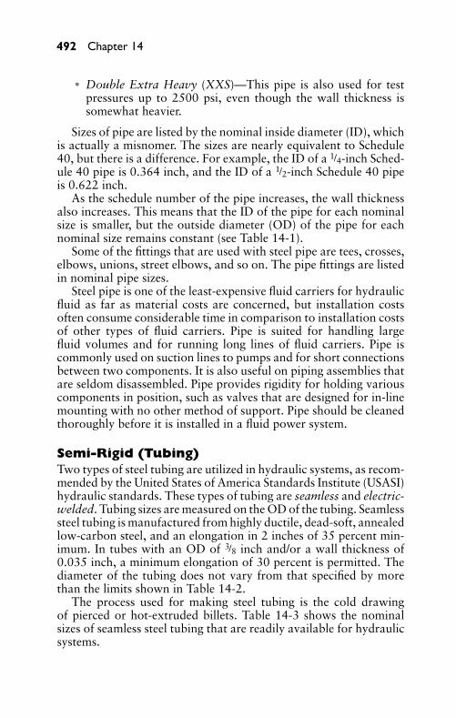
P1: FCH
GB098-14 GB098-Miller September 13, 2004 18:8 Char Count= 0
492 Chapter 14
� Double Extra Heavy (XXS)—This pipe is also used for testpressures up to 2500 psi, even though the wall thickness issomewhat heavier.
Sizes of pipe are listed by the nominal inside diameter (ID), whichis actually a misnomer. The sizes are nearly equivalent to Schedule40, but there is a difference. For example, the ID of a 1/4-inch Sched-ule 40 pipe is 0.364 inch, and the ID of a 1/2-inch Schedule 40 pipeis 0.622 inch.
As the schedule number of the pipe increases, the wall thicknessalso increases. This means that the ID of the pipe for each nominalsize is smaller, but the outside diameter (OD) of the pipe for eachnominal size remains constant (see Table 14-1).
Some of the fittings that are used with steel pipe are tees, crosses,elbows, unions, street elbows, and so on. The pipe fittings are listedin nominal pipe sizes.
Steel pipe is one of the least-expensive fluid carriers for hydraulicfluid as far as material costs are concerned, but installation costsoften consume considerable time in comparison to installation costsof other types of fluid carriers. Pipe is suited for handling largefluid volumes and for running long lines of fluid carriers. Pipe iscommonly used on suction lines to pumps and for short connectionsbetween two components. It is also useful on piping assemblies thatare seldom disassembled. Pipe provides rigidity for holding variouscomponents in position, such as valves that are designed for in-linemounting with no other method of support. Pipe should be cleanedthoroughly before it is installed in a fluid power system.
Semi-Rigid (Tubing)Two types of steel tubing are utilized in hydraulic systems, as recom-mended by the United States of America Standards Institute (USASI)hydraulic standards. These types of tubing are seamless and electric-welded. Tubing sizes are measured on the OD of the tubing. Seamlesssteel tubing is manufactured from highly ductile, dead-soft, annealedlow-carbon steel, and an elongation in 2 inches of 35 percent min-imum. In tubes with an OD of 3/8 inch and/or a wall thickness of0.035 inch, a minimum elongation of 30 percent is permitted. Thediameter of the tubing does not vary from that specified by morethan the limits shown in Table 14-2.
The process used for making steel tubing is the cold drawingof pierced or hot-extruded billets. Table 14-3 shows the nominalsizes of seamless steel tubing that are readily available for hydraulicsystems.
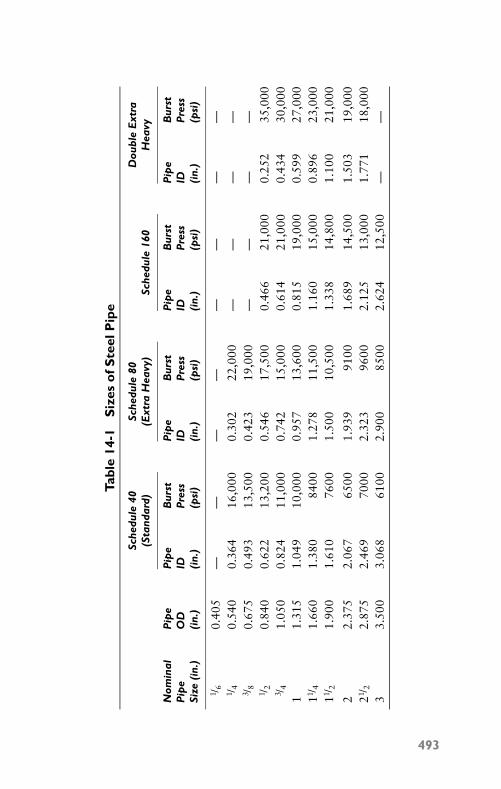
P1: FCH
GB098-14 GB098-Miller September 13, 2004 18:8 Char Count= 0
Tabl
e14
-1S
izes
ofS
teel
Pip
e
Sche
dule
40Sc
hedu
le80
Dou
ble
Ext
ra(S
tand
ard)
(Ext
raH
eavy
)Sc
hedu
le16
0H
eavy
Nom
inal
Pip
eP
ipe
Bur
stP
ipe
Bur
stP
ipe
Bur
stP
ipe
Bur
stP
ipe
OD
IDP
ress
IDP
ress
IDP
ress
IDP
ress
Size
(in.
)(i
n.)
(in.
)(p
si)
(in.
)(p
si)
(in.
)(p
si)
(in.
)(p
si)
1 /6
0.40
5—
——
——
——
—1 /
40.
540
0.36
416
,000
0.30
222
,000
——
——
3 /8
0.67
50.
493
13,5
000.
423
19,0
00—
——
—1 /
20.
840
0.62
213
,200
0.54
617
,500
0.46
621
,000
0.25
235
,000
3 /4
1.05
00.
824
11,0
000.
742
15,0
000.
614
21,0
000.
434
30,0
001
1.31
51.
049
10,0
000.
957
13,6
000.
815
19,0
000.
599
27,0
0011 /
41.
660
1.38
084
001.
278
11,5
001.
160
15,0
000.
896
23,0
0011 /
21.
900
1.61
076
001.
500
10,5
001.
338
14,8
001.
100
21,0
00
22.
375
2.06
765
001.
939
9100
1.68
914
,500
1.50
319
,000
21 /2
2.87
52.
469
7000
2.32
396
002.
125
13,0
001.
771
18,0
003
3.50
03.
068
6100
2.90
085
002.
624
12,5
00—
—
493
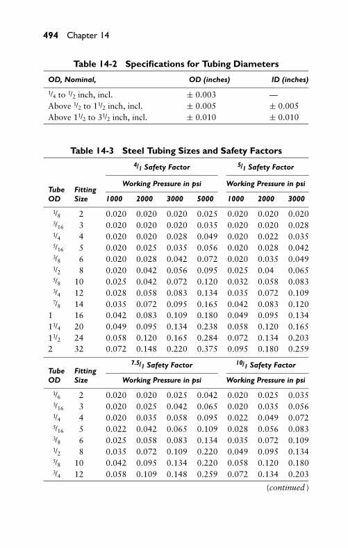
P1: FCH
GB098-14 GB098-Miller September 13, 2004 18:8 Char Count= 0
494 Chapter 14
Table 14-2 Specifications for Tubing Diameters
OD, Nominal, OD (inches) ID (inches)
1/4 to 1/2 inch, incl. ± 0.003 —Above 1/2 to 11/2 inch, incl. ± 0.005 ± 0.005Above 11/2 to 31/2 inch, incl. ± 0.010 ± 0.010
Table 14-3 Steel Tubing Sizes and Safety Factors4/1 Safety Factor 5/1 Safety Factor
Working Pressure in psi Working Pressure in psiTube FittingOD Size 1000 2000 3000 5000 1000 2000 3000
1/8 2 0.020 0.020 0.020 0.025 0.020 0.020 0.0203/16 3 0.020 0.020 0.020 0.035 0.020 0.020 0.0281/4 4 0.020 0.020 0.028 0.049 0.020 0.022 0.0355/16 5 0.020 0.025 0.035 0.056 0.020 0.028 0.0423/8 6 0.020 0.028 0.042 0.072 0.020 0.035 0.0491/2 8 0.020 0.042 0.056 0.095 0.025 0.04 0.0655/8 10 0.025 0.042 0.072 0.120 0.032 0.058 0.0833/4 12 0.028 0.058 0.083 0.134 0.035 0.072 0.1097/8 14 0.035 0.072 0.095 0.165 0.042 0.083 0.120
1 16 0.042 0.083 0.109 0.180 0.049 0.095 0.13411/4 20 0.049 0.095 0.134 0.238 0.058 0.120 0.16511/2 24 0.058 0.120 0.165 0.284 0.072 0.134 0.2032 32 0.072 0.148 0.220 0.375 0.095 0.180 0.259
7.5/1 Safety Factor 10/1 Safety FactorTube FittingOD Size Working Pressure in psi Working Pressure in psi
1/6 2 0.020 0.020 0.025 0.042 0.020 0.025 0.0353/16 3 0.020 0.025 0.042 0.065 0.020 0.035 0.0561/4 4 0.020 0.035 0.058 0.095 0.022 0.049 0.0725/16 5 0.022 0.042 0.065 0.109 0.028 0.056 0.0833/8 6 0.025 0.058 0.083 0.134 0.035 0.072 0.1091/2 8 0.035 0.072 0.109 0.220 0.049 0.095 0.1345/8 10 0.042 0.095 0.134 0.220 0.058 0.120 0.1803/4 12 0.058 0.109 0.148 0.259 0.072 0.134 0.203
(continued )
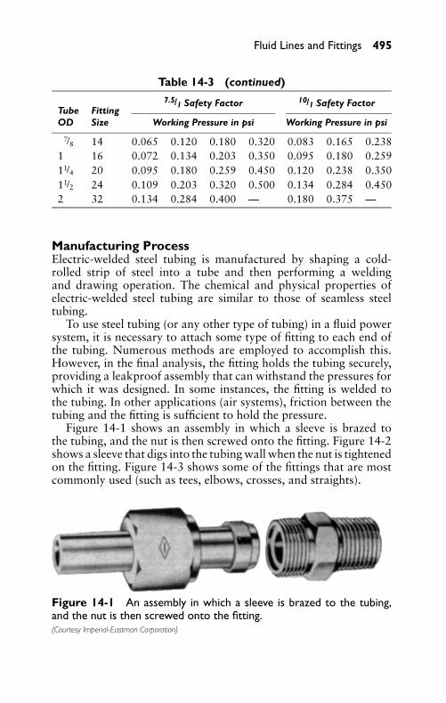
P1: FCH
GB098-14 GB098-Miller September 13, 2004 18:8 Char Count= 0
Fluid Lines and Fittings 495
Table 14-3 (continued)7.5/1 Safety Factor 10/1 Safety Factor
Tube FittingOD Size Working Pressure in psi Working Pressure in psi
7/8 14 0.065 0.120 0.180 0.320 0.083 0.165 0.2381 16 0.072 0.134 0.203 0.350 0.095 0.180 0.25911/4 20 0.095 0.180 0.259 0.450 0.120 0.238 0.35011/2 24 0.109 0.203 0.320 0.500 0.134 0.284 0.4502 32 0.134 0.284 0.400 — 0.180 0.375 —
Manufacturing ProcessElectric-welded steel tubing is manufactured by shaping a cold-rolled strip of steel into a tube and then performing a weldingand drawing operation. The chemical and physical properties ofelectric-welded steel tubing are similar to those of seamless steeltubing.
To use steel tubing (or any other type of tubing) in a fluid powersystem, it is necessary to attach some type of fitting to each end ofthe tubing. Numerous methods are employed to accomplish this.However, in the final analysis, the fitting holds the tubing securely,providing a leakproof assembly that can withstand the pressures forwhich it was designed. In some instances, the fitting is welded tothe tubing. In other applications (air systems), friction between thetubing and the fitting is sufficient to hold the pressure.
Figure 14-1 shows an assembly in which a sleeve is brazed tothe tubing, and the nut is then screwed onto the fitting. Figure 14-2shows a sleeve that digs into the tubing wall when the nut is tightenedon the fitting. Figure 14-3 shows some of the fittings that are mostcommonly used (such as tees, elbows, crosses, and straights).
Figure 14-1 An assembly in which a sleeve is brazed to the tubing,and the nut is then screwed onto the fitting.(Courtesy Imperial-Eastman Corporation)
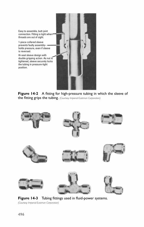
P1: FCH
GB098-14 GB098-Miller September 13, 2004 18:8 Char Count= 0
Easy to assemble, butt-jointconnection. Fitting is tight whenthreads are out of sight.
Hi-seal sleeve design with double gripping action. As nut istightened, sleeve securely locksthe tubing in pressure-tightposition.
1-piece collared sleeveprevents faulty assembly–holds pressure, even if sleeveis reversed.
Figure 14-2 A fitting for high-pressure tubing in which the sleeve ofthe fitting grips the tubing. (Courtesy Imperial-Eastman Corporation)
Figure 14-3 Tubing fittings used in fluid-power systems.(Courtesy Imperial-Eastman Corporation)
496

P1: FCH
GB098-14 GB098-Miller September 13, 2004 18:8 Char Count= 0
Fluid Lines and Fittings 497
Other TypesFollowing are other types of tubing employed in fluid power systems:
� Copper tubing—This type of tubing is often found on air cir-cuits that are not subject to USASI standards. Because of thework hardening when flared, and since it is an oil-oxidationcatalyst, USASI standards restrict the use of copper tubing forhydraulic service. Copper tubing can be worked easily to makebends that reduce fitting requirements.
� Aluminum tubing—Seamless aluminum tubing is approved forlow-pressure systems. This tubing has fine flaring and bendingcharacteristics.
� Plastic tubing—Plastic tubing for fluid power lines is madefrom several basic materials. Among these materials are nylon,polyvinyl, polyethylene, and polypropylene.� Nylon tubing—This tubing is used on fluid power applica-
tions in the low-pressure range, up to 250 psi. It is suitablefor a temperature range of minus 100◦F to plus 225◦F. Thistubing possesses good impact and abrasion resistance. It canbe stored without deteriorating or becoming brittle, and itis not affected by hydraulic fluids. One of the newer devel-opments is the self-storing type of nylon tubing that lookslike a coil spring; it is very popular for use on pneumatictools.
� Polyvinyl chloride tubing—For air lines with pressures upto 125 psi, this type of tubing may be used. Temperaturesshould not exceed 100◦F continuously. It may be used inter-mittently for temperatures up to 160◦F.
� Polyethylene tubing—This is ideal tubing for pneumatic ser-vice, and it is also used for other fluids at low pressures.It possesses great dimensional stability and resists mostchemicals and solvents. Polyethylene tubing is manufac-tured in several different colors that lend it readily to color-coding. Tubing sizes are usually available up to and including1/2-inch OD.
� Polypropylene tubing—This type of tubing is suitable foroperating conditions with temperatures of minus 20◦F toplus 280◦F, and it can be sterilized repeatedly with steam. Itpossesses surface hardness and elasticity that provide goodabrasion resistance. It is usually available in sizes up to andincluding 1/2-inch OD, in natural or black colors.
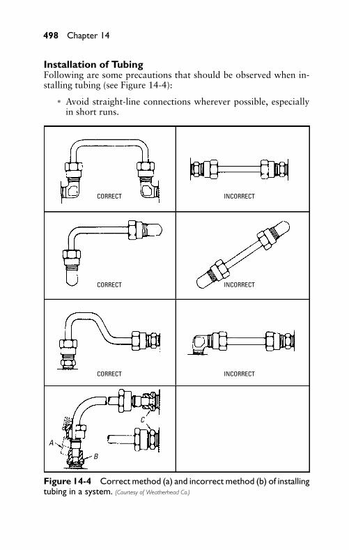
P1: FCH
GB098-14 GB098-Miller September 13, 2004 18:8 Char Count= 0
498 Chapter 14
Installation of TubingFollowing are some precautions that should be observed when in-stalling tubing (see Figure 14-4):
� Avoid straight-line connections wherever possible, especiallyin short runs.
CORRECT INCORRECT
INCORRECT
INCORRECT
CORRECT
CORRECT
C
A
B
Figure 14-4 Correct method (a) and incorrect method (b) of installingtubing in a system. (Courtesy of Weatherhead Co.)
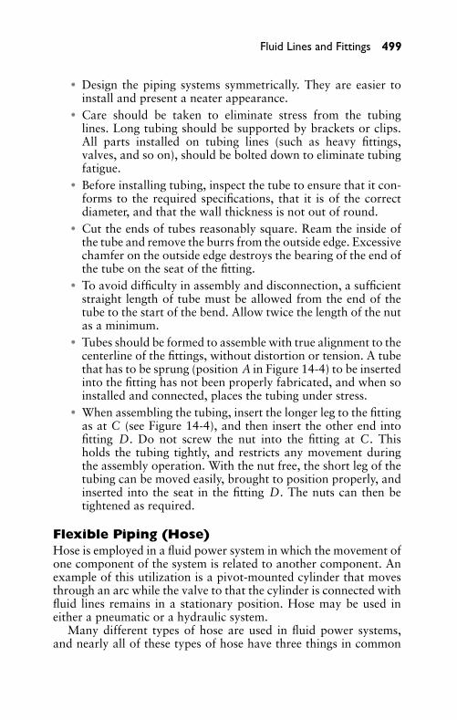
P1: FCH
GB098-14 GB098-Miller September 13, 2004 18:8 Char Count= 0
Fluid Lines and Fittings 499
� Design the piping systems symmetrically. They are easier toinstall and present a neater appearance.
� Care should be taken to eliminate stress from the tubinglines. Long tubing should be supported by brackets or clips.All parts installed on tubing lines (such as heavy fittings,valves, and so on), should be bolted down to eliminate tubingfatigue.
� Before installing tubing, inspect the tube to ensure that it con-forms to the required specifications, that it is of the correctdiameter, and that the wall thickness is not out of round.
� Cut the ends of tubes reasonably square. Ream the inside ofthe tube and remove the burrs from the outside edge. Excessivechamfer on the outside edge destroys the bearing of the end ofthe tube on the seat of the fitting.
� To avoid difficulty in assembly and disconnection, a sufficientstraight length of tube must be allowed from the end of thetube to the start of the bend. Allow twice the length of the nutas a minimum.
� Tubes should be formed to assemble with true alignment to thecenterline of the fittings, without distortion or tension. A tubethat has to be sprung (position A in Figure 14-4) to be insertedinto the fitting has not been properly fabricated, and when soinstalled and connected, places the tubing under stress.
� When assembling the tubing, insert the longer leg to the fittingas at C (see Figure 14-4), and then insert the other end intofitting D. Do not screw the nut into the fitting at C. Thisholds the tubing tightly, and restricts any movement duringthe assembly operation. With the nut free, the short leg of thetubing can be moved easily, brought to position properly, andinserted into the seat in the fitting D. The nuts can then betightened as required.
Flexible Piping (Hose)Hose is employed in a fluid power system in which the movement ofone component of the system is related to another component. Anexample of this utilization is a pivot-mounted cylinder that movesthrough an arc while the valve to that the cylinder is connected withfluid lines remains in a stationary position. Hose may be used ineither a pneumatic or a hydraulic system.
Many different types of hose are used in fluid power systems,and nearly all of these types of hose have three things in common
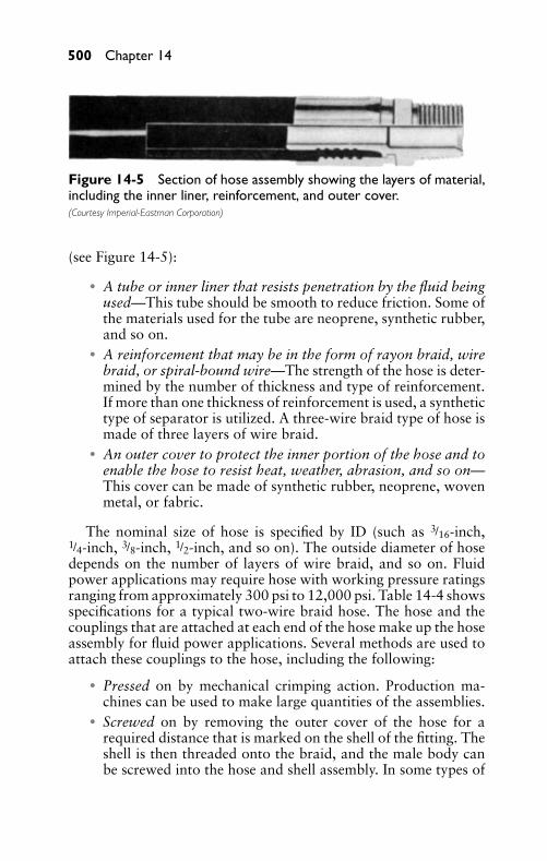
P1: FCH
GB098-14 GB098-Miller September 13, 2004 18:8 Char Count= 0
500 Chapter 14
Figure 14-5 Section of hose assembly showing the layers of material,including the inner liner, reinforcement, and outer cover.(Courtesy Imperial-Eastman Corporation)
(see Figure 14-5):
� A tube or inner liner that resists penetration by the fluid beingused—This tube should be smooth to reduce friction. Some ofthe materials used for the tube are neoprene, synthetic rubber,and so on.
� A reinforcement that may be in the form of rayon braid, wirebraid, or spiral-bound wire—The strength of the hose is deter-mined by the number of thickness and type of reinforcement.If more than one thickness of reinforcement is used, a synthetictype of separator is utilized. A three-wire braid type of hose ismade of three layers of wire braid.
� An outer cover to protect the inner portion of the hose and toenable the hose to resist heat, weather, abrasion, and so on—This cover can be made of synthetic rubber, neoprene, wovenmetal, or fabric.
The nominal size of hose is specified by ID (such as 3/16-inch,1/4-inch, 3/8-inch, 1/2-inch, and so on). The outside diameter of hosedepends on the number of layers of wire braid, and so on. Fluidpower applications may require hose with working pressure ratingsranging from approximately 300 psi to 12,000 psi. Table 14-4 showsspecifications for a typical two-wire braid hose. The hose and thecouplings that are attached at each end of the hose make up the hoseassembly for fluid power applications. Several methods are used toattach these couplings to the hose, including the following:
� Pressed on by mechanical crimping action. Production ma-chines can be used to make large quantities of the assemblies.
� Screwed on by removing the outer cover of the hose for arequired distance that is marked on the shell of the fitting. Theshell is then threaded onto the braid, and the male body canbe screwed into the hose and shell assembly. In some types of
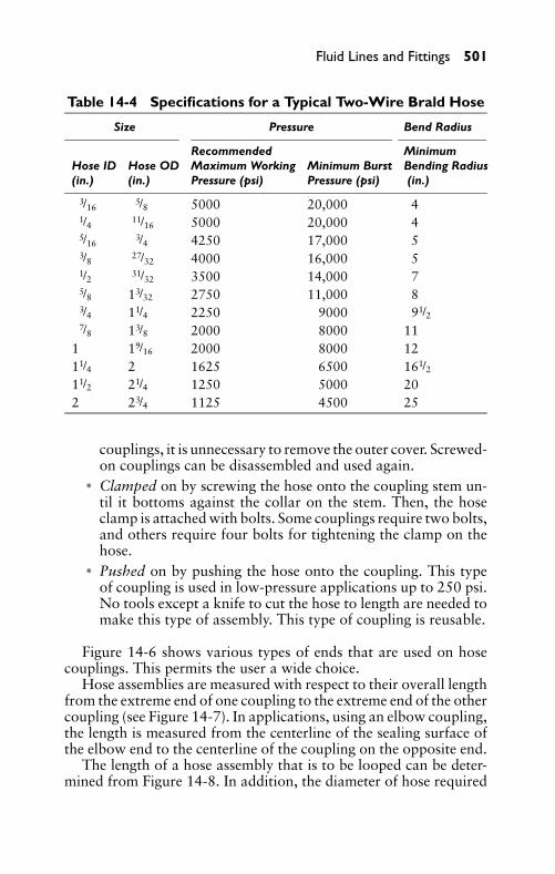
P1: FCH
GB098-14 GB098-Miller September 13, 2004 18:8 Char Count= 0
Fluid Lines and Fittings 501
Table 14-4 Specifications for a Typical Two-Wire Brald Hose
Size Pressure Bend Radius
Recommended MinimumHose ID Hose OD Maximum Working Minimum Burst Bending Radius(in.) (in.) Pressure (psi) Pressure (psi) (in.)
3/165/8 5000 20,000 4
1/4 11/16 5000 20,000 45/16
3/4 4250 17,000 53/8 27/32 4000 16,000 51/2 31/32 3500 14,000 75/8 13/32 2750 11,000 83/4 11/4 2250 9000 91/27/8 13/8 2000 8000 11
1 19/16 2000 8000 1211/4 2 1625 6500 161/211/2 21/4 1250 5000 202 23/4 1125 4500 25
couplings, it is unnecessary to remove the outer cover. Screwed-on couplings can be disassembled and used again.
� Clamped on by screwing the hose onto the coupling stem un-til it bottoms against the collar on the stem. Then, the hoseclamp is attached with bolts. Some couplings require two bolts,and others require four bolts for tightening the clamp on thehose.
� Pushed on by pushing the hose onto the coupling. This typeof coupling is used in low-pressure applications up to 250 psi.No tools except a knife to cut the hose to length are needed tomake this type of assembly. This type of coupling is reusable.
Figure 14-6 shows various types of ends that are used on hosecouplings. This permits the user a wide choice.
Hose assemblies are measured with respect to their overall lengthfrom the extreme end of one coupling to the extreme end of the othercoupling (see Figure 14-7). In applications, using an elbow coupling,the length is measured from the centerline of the sealing surface ofthe elbow end to the centerline of the coupling on the opposite end.
The length of a hose assembly that is to be looped can be deter-mined from Figure 14-8. In addition, the diameter of hose required
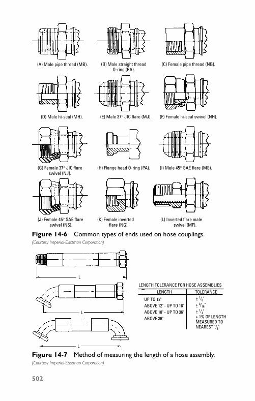
P1: FCH
GB098-14 GB098-Miller September 13, 2004 18:8 Char Count= 0
(A) Male pipe thread (MB).
(D) Male hi-seal (MH).
(G) Female 37° JIC flareswivel (NJ).
(H) Flange head O-ring (PA). (I) Male 45° SAE flare (MS).
(J) Female 45° SAE flare swivel (NS).
(K) Female inverted flare (NG).
(L) Inverted flare male swivel (MF).
(B) Male straight threadO-ring (RA).
(E) Male 37° JIC flare (MJ). (F) Female hi-seal swivel (NH).
(C) Female pipe thread (NB).
Figure 14-6 Common types of ends used on hose couplings.(Courtesy Imperial-Eastman Corporation)
L
L
L
LENGTH TOLERANCE FOR HOSE ASSEMBLIESLENGTH
UP TO 12"ABOVE 12" - UP TO 18"ABOVE 18" - UP TO 36"ABOVE 36"
+ 1/4"−+ 1% OF LENGTHMEASURED TONEAREST 1/8"
−
+ 3/16"−
+ 1/8"−
TOLERANCE
Figure 14-7 Method of measuring the length of a hose assembly.(Courtesy Imperial-Eastman Corporation)
502
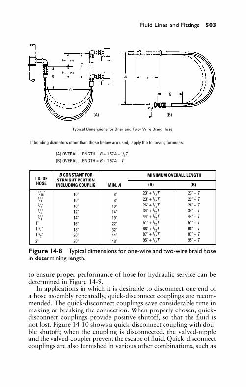
P1: FCH
GB098-14 GB098-Miller September 13, 2004 18:8 Char Count= 0
Fluid Lines and Fittings 503
TT
22
B
BA
A
T
T
(A) (B)
Typical Dimensions for One- and Two- Wire Braid Hose
If bending diameters other than those below are used, apply the following formulas:
(A) OVERALL LENGTH = B + 1.57A + 1/2T(B) OVERALL LENGTH = B + 1.57A + T
I.D. OFHOSE
3/16"1/4"3/8"1/2"3/4"
1"11/4"11/2"2"
B CONSTANT FORSTRAIGHT PORTIONINCLUDING COUPLIG
10"10"10"12"14"16"18"20"20"
MIN. A
8"8"
10"14"19"22"32"44"48"
MINIMUM OVERALL LENGTH
(A) (B)
23" + 1/2T23" + 1/2T26" + 1/2T34" + 1/2T44" + 1/2T51" + 1/2T68" + 1/2T87" + 1/2T95" + 1/2T
23" + T23" + T26" + T34" + T44" + T51" + T68" + T87" + T95" + T
Figure 14-8 Typical dimensions for one-wire and two-wire braid hosein determining length.
to ensure proper performance of hose for hydraulic service can bedetermined in Figure 14-9.
In applications in which it is desirable to disconnect one end ofa hose assembly repeatedly, quick-disconnect couplings are recom-mended. The quick-disconnect couplings save considerable time inmaking or breaking the connection. When properly chosen, quick-disconnect couplings provide positive shutoff, so that the fluid isnot lost. Figure 14-10 shows a quick-disconnect coupling with dou-ble shutoff; when the coupling is disconnected, the valved-nippleand the valved-coupler prevent the escape of fluid. Quick-disconnectcouplings are also furnished in various other combinations, such as
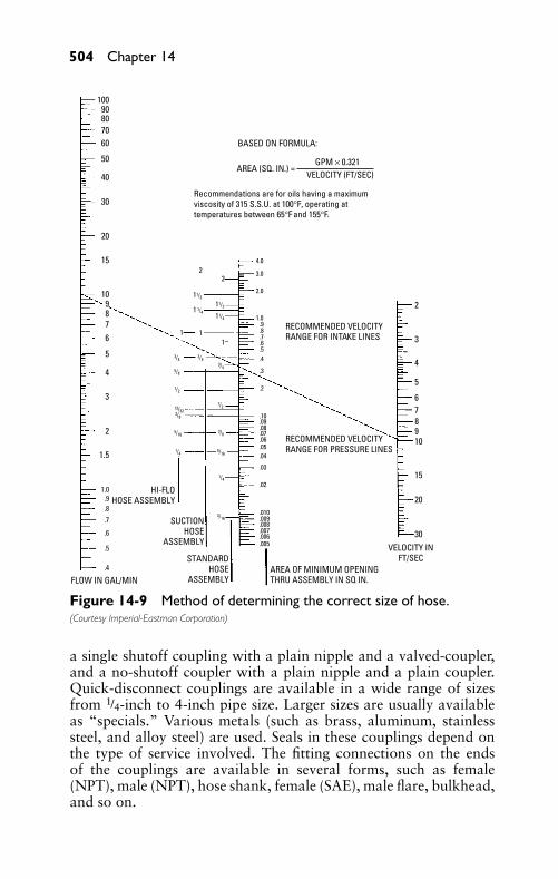
P1: FCH
GB098-14 GB098-Miller September 13, 2004 18:8 Char Count= 0
504 Chapter 14
10090807060
50
40
30
20
10
87
6
5
4
3
2
1.0
1.5
15
.9
.8
.7
.6
.5
.4
FLOW IN GAL/MIN
BASED ON FORMULA:
AREA (SQ. IN.) = VELOCITY (FT/SEC)
GPM × 0.321
Recommendations are for oils having a maximumviscosity of 315 S.S.U. at 100°F, operating attemperatures between 65°F and 155°F.
4.0
3.0
2.0
1.0.9.8.7.6.5.4
.3
.2
.10
.09
.08
.07
.06
.05
.04
.03
.02
.010
.009
.008
.007
.006
.005
STANDARDHOSE
ASSEMBLY
SUCTIONHOSE
ASSEMBLY
AREA OF MINIMUM OPENINGTHRU ASSEMBLY IN SQ IN.
HI-FLOHOSE ASSEMBLY
22
11/2
1 1/411/4
11/2
11
1
.
2
3
4
5
678910
15
20
30VELOCITY IN
FT/SEC
RECOMMENDED VELOCITYRANGE FOR PRESSURE LINES
RECOMMENDED VELOCITYRANGE FOR INTAKE LINES
3/4
3/16
3/43/4
5/8
5/16
5/16
1/2
1/2 13/32 3/8
3/8
1/4
1/4
9
Figure 14-9 Method of determining the correct size of hose.(Courtesy Imperial-Eastman Corporation)
a single shutoff coupling with a plain nipple and a valved-coupler,and a no-shutoff coupler with a plain nipple and a plain coupler.Quick-disconnect couplings are available in a wide range of sizesfrom 1/4-inch to 4-inch pipe size. Larger sizes are usually availableas “specials.” Various metals (such as brass, aluminum, stainlesssteel, and alloy steel) are used. Seals in these couplings depend onthe type of service involved. The fitting connections on the endsof the couplings are available in several forms, such as female(NPT), male (NPT), hose shank, female (SAE), male flare, bulkhead,and so on.
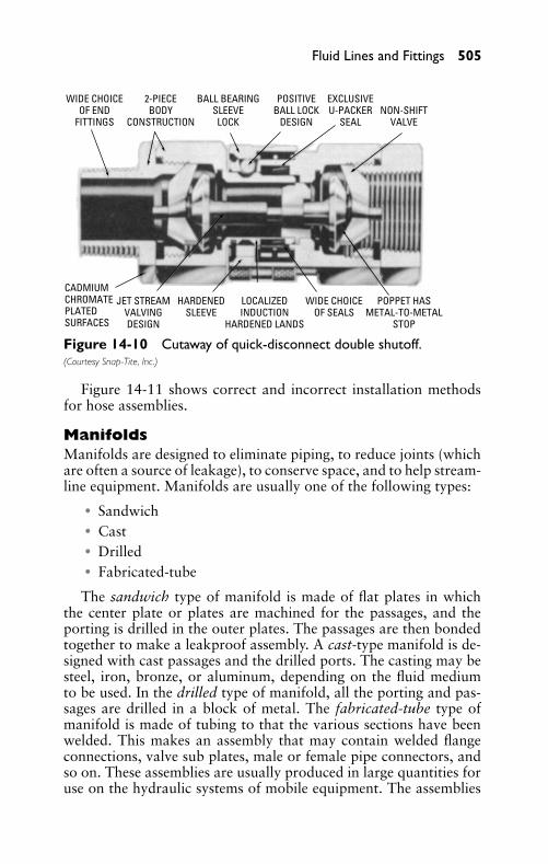
P1: FCH
GB098-14 GB098-Miller September 13, 2004 18:8 Char Count= 0
Fluid Lines and Fittings 505
WIDE CHOICEOF END
FITTINGS
2-PIECEBODY
CONSTRUCTION
BALL BEARINGSLEEVE
LOCK
POSITIVEBALL LOCK
DESIGN
EXCLUSIVEU-PACKER
SEALNON-SHIFT
VALVE
CADMIUMCHROMATEPLATEDSURFACES
JET STREAMVALVINGDESIGN
HARDENEDSLEEVE
LOCALIZEDINDUCTION
HARDENED LANDS
WIDE CHOICEOF SEALS
POPPET HASMETAL-TO-METAL
STOP
Figure 14-10 Cutaway of quick-disconnect double shutoff.(Courtesy Snap-Tite, Inc.)
Figure 14-11 shows correct and incorrect installation methodsfor hose assemblies.
ManifoldsManifolds are designed to eliminate piping, to reduce joints (whichare often a source of leakage), to conserve space, and to help stream-line equipment. Manifolds are usually one of the following types:
� Sandwich� Cast� Drilled� Fabricated-tube
The sandwich type of manifold is made of flat plates in whichthe center plate or plates are machined for the passages, and theporting is drilled in the outer plates. The passages are then bondedtogether to make a leakproof assembly. A cast-type manifold is de-signed with cast passages and the drilled ports. The casting may besteel, iron, bronze, or aluminum, depending on the fluid mediumto be used. In the drilled type of manifold, all the porting and pas-sages are drilled in a block of metal. The fabricated-tube type ofmanifold is made of tubing to that the various sections have beenwelded. This makes an assembly that may contain welded flangeconnections, valve sub plates, male or female pipe connectors, andso on. These assemblies are usually produced in large quantities foruse on the hydraulic systems of mobile equipment. The assemblies
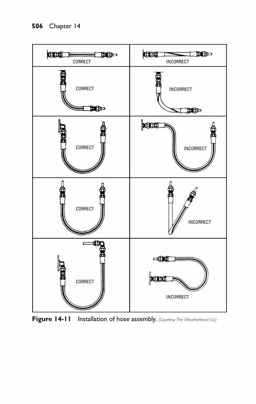
P1: FCH
GB098-14 GB098-Miller September 13, 2004 18:8 Char Count= 0
506 Chapter 14
CORRECT
CORRECT
CORRECT
CORRECT
CORRECT
INCORRECT
INCORRECT
INCORRECT
INCORRECT
INCORRECT
Figure 14-11 Installation of hose assembly. (Courtesy The Weatherhead Co.)
P1: FCH
GB098-14 GB098-Miller September 13, 2004 18:8 Char Count= 0
Fluid Lines and Fittings 507
are held to close tolerances, because they are manufactured in fix-tures. Although manifolds are used mostly on hydraulic systems, thedemand for them in pneumatic systems is increasing.
SummaryFluid lines or piping is found in three categories: rigid, semi-rigid,or tubing (flexible or hose). In many instances, all three categoriesof piping are employed in a single fluid system.
The size of rigid pipe is indicated by the nominal inside dia-meter (ID), that is actually a misnomer. For example, the insidediameter of a 1/4-inch Schedule 40 pipe is 0.364 inch, and the insidediameter of a 1/2-inch Schedule 40 pipe is 0.622 inch.
Two types of steel tubing are utilized in hydraulic systems, asrecommended by USASI hydraulic standards: seamless and electric-welded. Tubing size is indicated by the nominal outside diameter(OD) of the tubing.
Flexible pipe (hose) is utilized in a fluid power system in whichthe movement of one component of the system is related to anothercomponent. The size of a hose is indicated by the nominal ID (suchas 3/16-inch, 1/4-inch, and so on).
Manifolds are designed to eliminate piping, to reduce joints thatare often a source of leakage, to conserve space, and to help stream-line modern-day equipment. Manifolds are usually one of the fol-lowing types: sandwich, cast, drilled, and fabricated-tube.
Review Questions1. List the three types of fluid lines or piping.2. What are the advantages of steel pipe as a fluid carrier?3. What are three types of tubing commonly used in fluid power
systems?4. What is the chief advantage of hose in fluid power systems?5. What is the chief advantage of manifolds in fluid power sys-
tems?6. How may the efficiency of a fluid power system become lim-
ited?7. What does Schedule 40 pipe mean as compared to Schedule
80?8. Describe where XXS pipe is used.9. What is one of the least expensive fluid carriers for hydraulic
fluids?
P1: FCH
GB098-14 GB098-Miller September 13, 2004 18:8 Char Count= 0
508 Chapter 14
10. What is the outside diameter of a 3/4-inch pipe?11. What is the ID of a 1-inch Schedule 80 pipe?12. Why is copper tubing restricted for hydraulic service?13. For what type of systems is seamless aluminum tubing used?14. What are the types of materials used in making plastic tubing
for fluid power lines?15. What is the recommended maximum working pressure for a
1-inch ID two-wire braid hose?16. What does NPT mean?17. List four types of manifolds.18. What are the two types of steel tubing used in hydraulic lines?
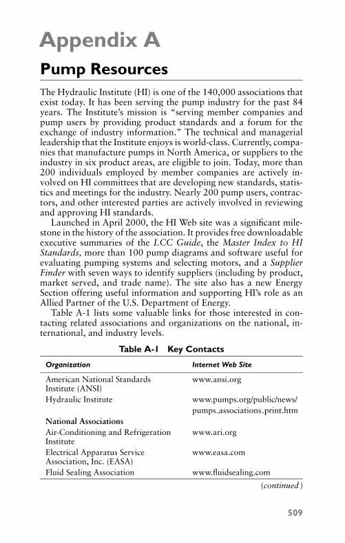
P1: JYC
GB098-AppA GB098-Miller September 11, 2004 4:38 Char Count= 0
Appendix APump ResourcesThe Hydraulic Institute (HI) is one of the 140,000 associations thatexist today. It has been serving the pump industry for the past 84years. The Institute’s mission is “serving member companies andpump users by providing product standards and a forum for theexchange of industry information.” The technical and managerialleadership that the Institute enjoys is world-class. Currently, compa-nies that manufacture pumps in North America, or suppliers to theindustry in six product areas, are eligible to join. Today, more than200 individuals employed by member companies are actively in-volved on HI committees that are developing new standards, statis-tics and meetings for the industry. Nearly 200 pump users, contrac-tors, and other interested parties are actively involved in reviewingand approving HI standards.
Launched in April 2000, the HI Web site was a significant mile-stone in the history of the association. It provides free downloadableexecutive summaries of the LCC Guide, the Master Index to HIStandards, more than 100 pump diagrams and software useful forevaluating pumping systems and selecting motors, and a SupplierFinder with seven ways to identify suppliers (including by product,market served, and trade name). The site also has a new EnergySection offering useful information and supporting HI’s role as anAllied Partner of the U.S. Department of Energy.
Table A-1 lists some valuable links for those interested in con-tacting related associations and organizations on the national, in-ternational, and industry levels.
Table A-1 Key Contacts
Organization Internet Web Site
American National StandardsInstitute (ANSI)
www.ansi.org
Hydraulic Institute www.pumps.org/public/news/pumps associations print.htm
National AssociationsAir-Conditioning and RefrigerationInstitute
www.ari.org
Electrical Apparatus ServiceAssociation, Inc. (EASA)
www.easa.com
Fluid Sealing Association www.fluidsealing.com
(continued )
509
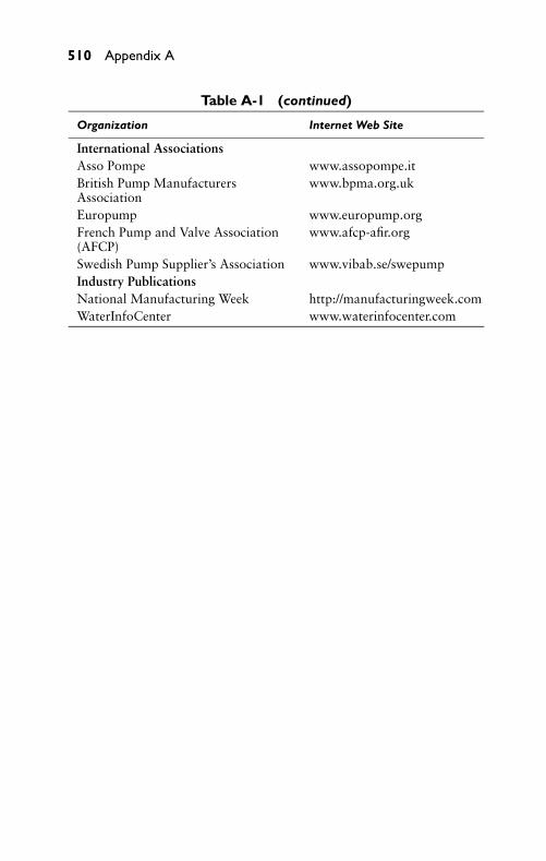
P1: JYC
GB098-AppA GB098-Miller September 11, 2004 4:38 Char Count= 0
510 Appendix A
Table A-1 (continued)
Organization Internet Web Site
International AssociationsAsso Pompe www.assopompe.itBritish Pump ManufacturersAssociation
www.bpma.org.uk
Europump www.europump.orgFrench Pump and Valve Association(AFCP)
www.afcp-afir.org
Swedish Pump Supplier’s Association www.vibab.se/swepumpIndustry PublicationsNational Manufacturing Week http://manufacturingweek.comWaterInfoCenter www.waterinfocenter.com
P1: JYC
GB098-AppB GB098-Miller September 11, 2004 4:39 Char Count= 0
Appendix BOils and FluidsA number of synthetic oils and fluids are available for use withhigh-speed compressor pumps and are recommended for use insingle-stage and multi-stage rotary screw, vane, and reciprocatingcompressor crankcases and cylinders, vacuum pumps, and othercompressor applications. Most of these are available in five viscositygrades. These synthetic oils have a number of additives that makethem capable of inhibiting carbon build-up and that make themsuitable for operating equipment at higher temperatures. Most areformulated to keep water from mixing with the oil and deterioratingits lubricating ability. Manufacturers also claim it is easier for waterremoval with no need for specialized water-removal processes.
For example, the synthetic compressor oil is formulated with syn-thetic ester technology that produces a longer life fluid that effec-tively prevents wear, oxidation, foam, and rust, while its inherentlubricity and thermal conductivity act to reduce heat and energyconsumption. This increases the operating efficiency and reducesmaintenance costs.
Performance features are maintained across the spectrum with awide operating temperature range. It has a low pour-point, high-viscosity index and the lack of paraffin (wax) makes synthetic oilsan excellent all-weather lubricant.
Hydraulic oils are formulated for long life. They typically re-duce maintenance costs. This is done by extending drain intervals.AMSOIL’s synthetic AW series of anti-wear hydraulic oils, for ex-ample, are recommended for high- and low-pressure gear, vane, andpiston stationary and mobile hydraulic systems. They are availablein many viscosity grades. The equipment manufacturer usually rec-ommends the viscosity for the device. The oil will operate efficientlyin temperatures of –20◦F or lower. These oils are shear-stable, long-life lubricants based on high-quality synthetic oil technology. Theseoils are formulated with an additive system that inhibits oxidationand prevents acid and viscosity increase, inhibits rust, and inhibitsfoam formation, as well as preventing spongy hydraulics.
There is also thermally stable biodegradable hydraulic oil thatis designed to biodegrade to its natural state when subjected tosunlight, water, and microbial activity. It has a very low toxicitylevel because the oil is formulated with ashless additives that do notcontain heavy metals.
Traditional oil-lubricated pumps use oil for lubricating, cooling,and sealing. Oil reduces the friction of pistons or vanes that must
511
P1: JYC
GB098-AppB GB098-Miller September 11, 2004 4:39 Char Count= 0
512 Appendix B
slide against the cylinder walls. Older-style rotary vane pumps useddrip oilers. The oil merely reduced friction, but newer oil-floodeddesigns use copious amounts of oil and actually cause the vanes tohydroplane. This not only reduces the friction, but since the vanes donot actually touch the cylinder wall, the vane life is greatly extended.It is common to obtain 30,000 to 40,000 hours of vane life.
Oil removes the heat of friction. When oil returns to the oil sump(or reservoir), the heat is radiated away from the pump. A fan usuallyblows across cooling fins on the housing. This exchange of heat isimportant. If oil runs too hot, it carbonizes. Carbonization can causethe pump to overheat and eventually cause its failure.
The amount of oil being fed to the pump affects sealing. Drip-typeoilers on rotary vane pumps need sufficient oil to seal the clearancesaround the vanes. Oil is used primarily for lubrication. The oil sealhas a significant internal leakage of air to the pump. This limits thevacuum level the pump can produce. A typical rotary-vane pump ofthis type can generally produce a maximum vacuum level of about26 to 27 inches of mercury. The more recent oil-flooded rotary-vanedesigns use a greater quantity of oil (sometimes as much as 2 gallonsper minute) to seal these clearances. This increases the efficiency ofthe pump and allows maximum vacuum levels of as much as 29.83inches of mercury. The maximum vacuum achievable at sea level is29.92 inches of mercury. Rotary-screw pumps are oil-flooded so theycan achieve higher vacuum levels with 29.7 inches of mercury beingtypical. In addition to cooling, oil is used to keep the rotors fromtouching each other. Most rotary-screw pumps do not use timinggears to drive the rotors. To prevent contact, one rotor drives theother.
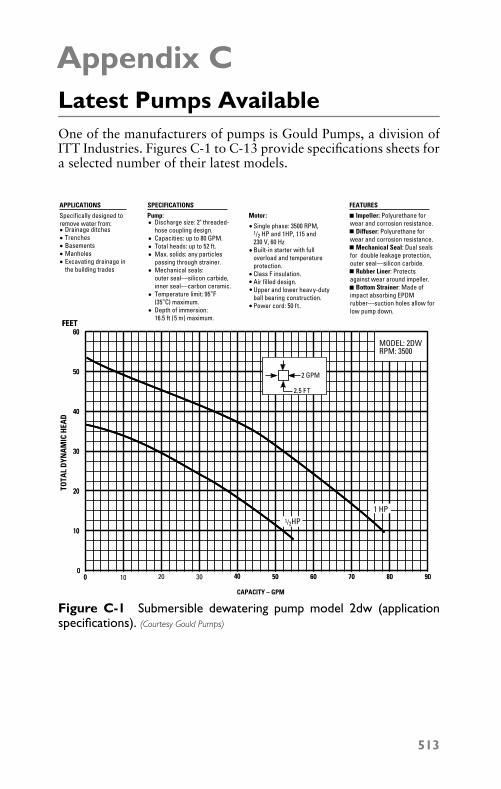
P1: JYC
GB098-AppC GB098-Miller August 11, 2004 11:24 Char Count= 0
Appendix CLatest Pumps AvailableOne of the manufacturers of pumps is Gould Pumps, a division ofITT Industries. Figures C-1 to C-13 provide specifications sheets fora selected number of their latest models.
SPECIFICATIONS
Pump:Discharge size: 2" threaded-hose coupling design.Capacities: up to 80 GPM.Total heads: up to 52 ft.Max. solids: any particlespassing through strainer.Mechanical seals:outer seal—silicon carbide,inner seal—carbon ceramic.Temperature limit: 95°F (35°C) maximum.Depth of immersion:16.5 ft ( 5 m) maximum.
APPLICATIONS
Specifically designed toremove water from:
Drainage ditchesTrenchesBasementsManholesExcavating drainage inthe building trades
CAPACITY – GPM
Single phase: 3500 RPM,1/2 HP and 1HP, 115 and230 V, 60 HzBuilt-in starter with fulloverload and temperatureprotection.Class F insulation.Air filled design.Upper and lower heavy-dutyball bearing construction.Power cord: 50 ft.
Motor:
FEATURES
Impeller: Polyurethane forwear and corrosion resistance. Diffuser: Polyurethane forwear and corrosion resistance. Mechanical Seal: Dual sealsfor double leakage protection,outer seal—silicon carbide. Rubber Liner: Protectsagainst wear around impeller. Bottom Strainer: Made of impact absorbing EPDMrubber—suction holes allow forlow pump down.
0 10 20 30 40 50 60 70 800
30
20
10
TOTA
L D
YNA
MIC
HEA
D
FEET
40
50
60
90
1 ⁄2 HP
1 HP
2.5 F T
2 GPM
MODEL: 2DWRPM: 3500
0 40 50 60 70 800
30
20
10
FEET
40
50
60
90
1/2HP1 HP
2.5 FT
2 GPM
Figure C-1 Submersible dewatering pump model 2dw (applicationspecifications). (Courtesy Gould Pumps)
513
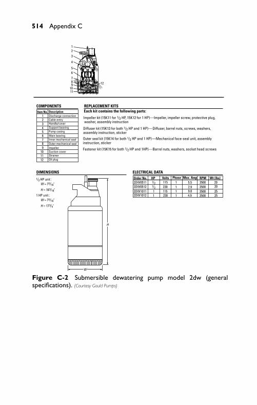
P1: JYC
GB098-AppC GB098-Miller August 11, 2004 11:24 Char Count= 0
514 Appendix C
Item No. Description
ELECTRICAL DATAOrder No. HP Volts Phase Max. Amp RPM Wt (lbs)2DW05112DW05122DW10112DW1012
1/21/2
11
11
11
115230115230
5.52.99.84.9
3500350035003500
20202525
1/2 HP unit :
1 HP unit :
W = 75/16"
H = 163/18"
W = 75/16"
H = 173/4"
123456789
1011
Discharge connectionCable entryHandle/coverSupport bearingPump casingMain bearingInner mechanical sealOuter mechanical sealImpellerSuction coverStrainerOil plug12
Each kit contains the following parts:
Impeller kit (15K11 for 1/2 HP, 15K12 for 1 HP)—Impeller, impeller screw, protective plug, washer, assembly instruction
Diffuser kit (15K13 for both 1/2 HP and 1 HP)—Diffuser, barrel nuts, screws, washers, assembly instruction, sticker
Outer seal kit (15K14 for both 1/2 HP and 1 HP)—Mechanical face-seal unit, assemblyinstruction, sticker
Fastener kit (15K15 for both 1/2 HP and 1HP)— Barrel nuts, washers, socket head screws
H
W
11
1210987
65
4
321
COMPONENTS REPLACEMENT KITS
DIMENSIONS
Figure C-2 Submersible dewatering pump model 2dw (generalspecifications). (Courtesy Gould Pumps)
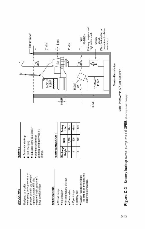
P1: JYC
GB098-AppC GB098-Miller August 11, 2004 11:24 Char Count= 0
SUM
P
1.6
REF
PRIM
ARY
PUM
P
FLOA
T SW
SW
2" M
IN
2" M
IN
(Prim
ary
pum
p no
rmal
hig
h w
ater
leve
l)
CHEC
KVA
LVE
(Mus
t be
inst
alle
d to
p
reve
nt re
circ
ulat
ion
into
sum
p.)
"ON
" PO
SITI
ON
TOP
OF S
UMP
11/ 2
M
AX 11/ 2
M
AX
BACK
UP
PUM
P
Stan
dard
Inst
alla
tion
NOT
E: P
RIM
ARY
PUM
P N
OT IN
CLUD
ED.
APPL
ICAT
ION
S
SPEC
IFIC
ATIO
NS
PERF
ORM
AN
CE C
HA
RT
FEAT
URE
S
Desi
gned
to p
rovi
de
emer
genc
y ba
ckup
ser
vice
for
prim
ary
pum
p in
the
even
t of
a po
wer
out
age.
Will
als
o op
erat
e if
mai
n pu
mp
can’
t ke
ep u
p w
ith in
flow
.
Auto
mat
ic s
tart-
upSe
lf-ch
argi
ngIn
dica
tor l
ight
s on
cha
rger
A
larm
sou
nds
whe
n pu
mpi
ng a
nd b
atte
ry w
on' t
ch
arge
.
12-v
olt p
ump
Floa
t sw
itch
10-a
mp
batte
ry c
harg
erCh
eck
valv
ePi
pe fi
tting
sBa
ttery
box
Syst
em re
quire
s m
inim
um
105-
amp
deep
-cyc
le m
arin
e ba
ttery
(not
incl
uded
).
Dis
char
ge
Hei
ght
GPH
Bat
tery
Li
fe5' 10'
13'
1,38
0
900
480
9 hr
s
9 hr
s
11 h
rs
C TE
EL
Fig
ure
C-3
Batt
ery
back
upsu
mp
pum
pm
odel
SPBB
.(Co
urte
syG
ould
Pum
ps)
515
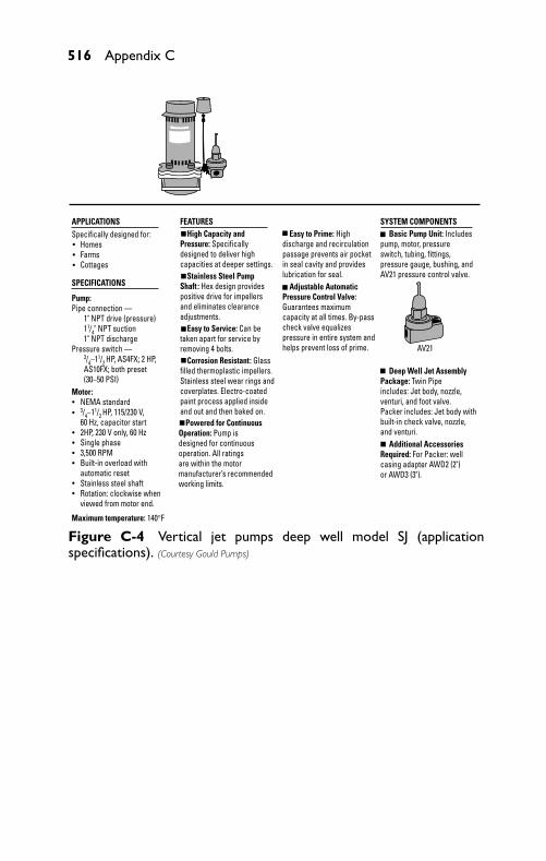
P1: JYC
GB098-AppC GB098-Miller August 11, 2004 11:24 Char Count= 0
516 Appendix C
Easy to Prime: Highdischarge and recirculationpassage prevents air pocketin seal cavity and provideslubrication for seal. Adjustable AutomaticPressure Control Valve: Guarantees maximumcapacity at all times. By-passcheck valve equalizespressure in entire system andhelps prevent loss of prime.
FEATURES High Capacity andPressure: Specificallydesigned to deliver highcapacities at deeper settings. Stainless Steel PumpShaft : Hex design providespositive drive for impellersand eliminates clearanceadjustments. Easy to Service: Can betaken apart for service byremoving 4 bolts. Corrosion Resistant: Glassfilled thermoplastic impellers.Stainless steel wear rings andcoverplates. Electro-coatedpaint process applied inside and out and then baked on. Powered for ContinuousOperation: Pump isdesigned for continuousoperation. All ratingsare within the motormanufacturer’s recommendedworking limits.
APPLICATIONS
SPECIFICATIONS
Specifically designed for: Homes Farms Cottages
Pump:Pipe connection — 1" NPT drive (pressure) 11/4" NPT suction 1" NPT dischargePressure switch — 3/4–11/2 HP, AS4FX; 2 HP, AS10FX; both preset (30–50 PSI)
Maximum temperature: 140°F
Motor: NEMA standard 3/4–11/2 HP, 115/230 V, 60 Hz, capacitor start 2HP, 230 V only, 60 Hz Single phase 3,500 RPM Built-in overload with automatic reset Stainless steel shaft Rotation: clockwise when viewed from motor end.
SYSTEM COMPONENTS Basic Pump Unit: Includespump, motor, pressureswitch, tubing, fittings,pressure gauge, bushing, andAV21 pressure control valve.
Deep Well Jet AssemblyPackage: Twin Pipeincludes: Jet body, nozzle,venturi, and foot valve.Packer includes: Jet body withbuilt-in check valve, nozzle,and venturi. Additional AccessoriesRequired: For Packer: wellcasing adapter AWD2 (2")or AWD3 (3").
AV21
Figure C-4 Vertical jet pumps deep well model SJ (applicationspecifications). (Courtesy Gould Pumps)
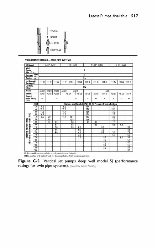
P1: JYC
GB098-AppC GB098-Miller August 11, 2004 11:24 Char Count= 0
Latest Pumps Available 517
30 15.213.511.810.78.5 9.0
7.56.2
11.710.59.07.56.3
9.39.0
8.07.06.2
6.85.75.55.35.04.73.8
9.48.57.7
6.0
9.5
5.85.6
9.511.312.012.812.813.013.013.0
5.24.74.23.73.2
9.210.612.212.813.013.013.0
6.05.04.34.03.5
11.713.714.715.216.0
6.25.85.04.64.0
405060708090
100110120130140150160170180190200
PERFORMANCE RATINGS — TWIN PIPE SYSTEMS
HP/ModelWellCasingMin. I.D. in.PressureSuctionJet AssemblyPackage (1)Jet Body(Only)NozzleVenturiControlValve Setting(PSI)
PipeSize(in.)
FT4-48 FT4-47 FT4-06 FT4-47 FT4-24 FT4-08 FT4-45 FT4-30 FT4-29 FT4-45 FT4-30 FT4-29
37 40 43 62 65 67 76 78 80
AN012AD727 AD724 AD720 AD724 AD720 AD726 AD722 AD719 AD726 AD722 AD719
AN013 AN013 AN013AN014 AN015
Feet
3/4 HP–SJ07 11/2 HP–SJ151 HP–SJ10 2 HP–SJ20
4
111/4
AT4
Gallons per Minute (GPM) 30–50 Pressure Switch Setting
Dept
h to
Jet
Ass
embl
y(B
ased
on
Subm
erge
nce
of 5
feet
)
(1) Jet assembly package includes jet body, venturi, nozzle, foot valve.NOTE: An offset of 50 feet will result in a decrease of about 25% from ratings as shown.
VENTURI
NOZZLE
JET BODY
FOOT VALVE
Figure C-5 Vertical jet pumps deep well model SJ (performanceratings for twin pipe systems). (Courtesy Gould Pumps)
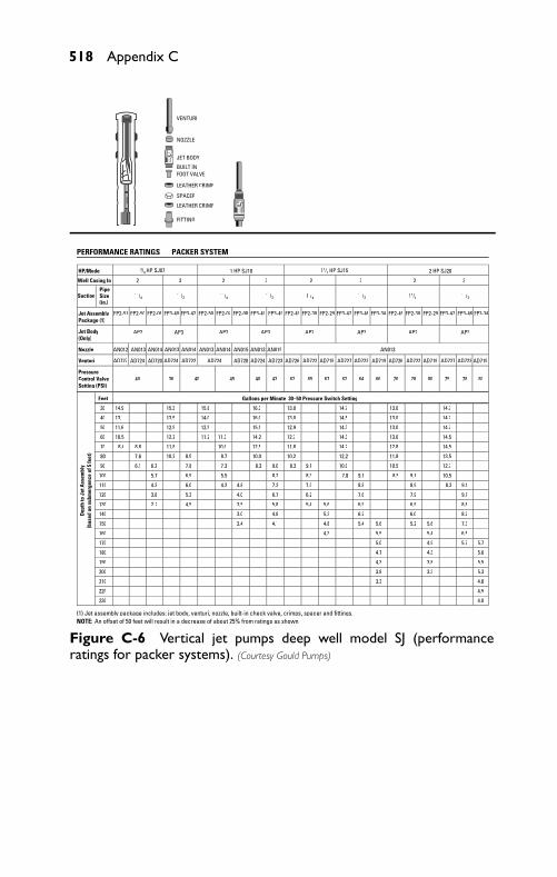
P1: JYC
GB098-AppC GB098-Miller August 11, 2004 11:24 Char Count= 0
518 Appendix C
FP2-51 FP2-50 FP2-06 FP3-40 FP3-42 FP2-50 FP2-07 FP2-08 FP3-40 FP3-49 FP2-49 FP2-30 FP2-29 FP3-47 FP3-46 FP3-34 FP2-49 FP2-30 FP2-29 FP3-47 FP3-46 FP3-34
AP2 AP2 AP3 AP2 AP3 AP2 AP3
PERFORMANCE RATINGS — PACKER SYSTEM
Dep
th to
Jet
Ass
embl
y (b
ased
on
subm
erge
nce
of 5
feet
)
LEATHER CRIMP
SPACER
LEATHER CRIMP
FITTING
HP/Model 1 HP SJ10 1 /2 HP SJ15 2 HP SJ20
Well Casing In. 2 3 32 2 3
Suction 11/4 11/4 11/4 11/4
Jet AssemblyPackage (1)
Jet Body(Only)
Nozzle AN013 AN014 AN015
Venturi AD727 AD724 AD722 AD724 AD723 AD726 AD722 AD719 AD727 AD722 AD719 AD726 AD722 AD719 AD727 AD722 AD719
Control Valve 40 36 40 45 40 43 62 65 67 62 64 66 76 78 80 75 78 80Setting (PSI)
Feet Gallons per Minute 30–50 Pressure Switch Setting
30 14.9 15.3 15.8 16.3 13.0 14.7 13.0 14.7
40 13.1 13.5 14.0 16.0 13.0 14.5 13.0 14.7
50 11.6 12.5 12.5 15.5 12.9 14.3 13.0 14.7
60 12.2 11.2 11.3 14.2 12.7 14.3 13.0 14.5
70 8.4 8.8 11.8 10.0 12.5 11.8 14.2 12.8 14.5
10.2 8.5 8.7 10.0 10.2 11.8 13.5
90 6.1 6.2 7.8 7.3 8.3 9.0 8.3 9.1 10.0 10.5 12.7
100 6.9 8.2 8.3 8.5 9.1
110 4.3 6.0 4.2 4.8 7.3 7.3 8.8 8.9 8.3 9.1
120 3.8 5.3 4.0 6.7 6.2 7.6 7.9 9.1
130 2.2 4.5 3.5 5.8 5.4 5.6 6.9 6.9 8.8
140 3.0 4.8 5.3 6.2 6.0 8.2
150 2.4 4.1 4.8 5.4 5.6 5.2 5.6 7.3
160 4.3 5.5 5.4 6.5
170 5.0 4.9 5.7 5.7
180 4.7 4.3 5.6
190 4.3 3.8 5.5
200 3.8 3.3 5.3
210 3.3 4.8
220 4.5
230 4.0
(1) Jet assembly package includes: jet body, venturi, nozzle, built-in check valve, crimps, spacer and fittings.NOTE: An offset of 50 feet will result in a decrease of about 25% from ratings as shown.
PipeSize(in.)
11/2 11/2 11/2 11/2
3
Figure C-6 Vertical jet pumps deep well model SJ (performanceratings for packer systems). (Courtesy Gould Pumps)
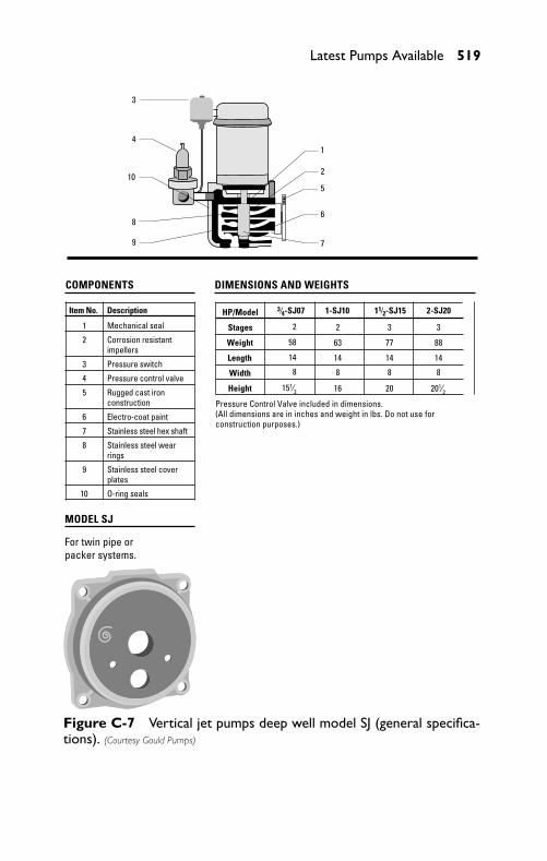
P1: JYC
GB098-AppC GB098-Miller August 11, 2004 11:24 Char Count= 0
Latest Pumps Available 519
MODEL SJ
1
2
5
6
7
3
4
10
8
9
COMPONENTS
Item No. Description
1 Mechanical seal
2 Corrosion resistantimpellers
3 Pressure switch
4 Pressure control valve
5 Rugged cast ironconstruction
6 Electro-coat paint
7 Stainless steel hex shaft
8 Stainless steel wearrings
9 Stainless steel coverplates
10 O-ring seals
For twin pipe or packer systems.
DIMENSIONS AND WEIGHTS
HP/Model 3⁄4-SJ07 1-SJ10 11⁄2-SJ15 2-SJ20
Stages
Weight 58 63 77 88
Length 14 14 14 14
Width
Height 151⁄2 16 20 201⁄2Pressure Control Valve included in dimensions.(All dimensions are in inches and weight in lbs. Do not use for construction purposes.)
2
8
2
8
3
8
3
8
+
Figure C-7 Vertical jet pumps deep well model SJ (general specifica-tions). (Courtesy Gould Pumps)
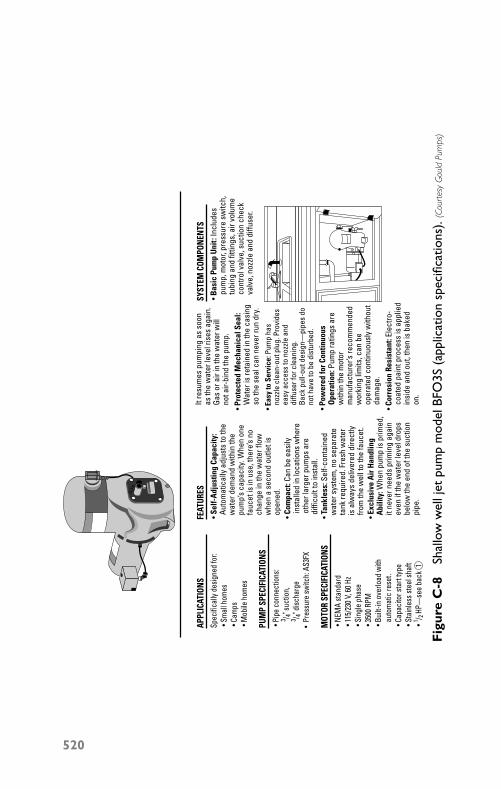
P1: JYC
GB098-AppC GB098-Miller August 11, 2004 11:24 Char Count= 0
APPL
ICAT
IONS
Spec
ifica
lly d
esig
ned
for:
• Sm
all h
omes
• Ca
mps
• M
obile
hom
es
FEAT
URES
• Se
lf-A
djus
ting
Capa
city
:
Auto
mat
ical
ly a
djus
ts to
the
w
ater
dem
and
with
in th
e
pum
p’s
capa
city
. Whe
n on
e
fauc
et is
in u
se, t
here
’s no
ch
ange
in th
e w
ater
flow
w
hen
a se
cond
out
let i
s
open
ed.
It
resu
mes
pum
ping
as
soon
as
the
wat
er le
vel r
ises
aga
in.
Ga
s or
air
in th
e w
ater
will
not a
ir-bi
nd th
e pu
mp.
• Pro
tect
ed M
echa
nica
l Sea
l:
Wat
er is
reta
ined
in th
e ca
sing
so
the
seal
can
nev
er ru
n dr
y.
• Bas
ic P
ump
Uni
t: In
clud
es
pum
p, m
otor
, pre
ssur
e sw
itch,
tu
bing
and
fitti
ngs,
air
volu
me
co
ntro
l val
ve, s
uctio
n ch
eck
va
lve,
noz
zle a
nd d
iffus
er.
• Eas
y to
Ser
vice
: Pum
p ha
s
nozz
le c
lean
-out
plu
g. P
rovi
des
ea
sy a
cces
s to
noz
zle a
nd
di
ffuse
r for
cle
anin
g.
Back
pul
l-out
des
ign—
pipe
s do
no
t hav
e to
be
dist
urbe
d.
• Pow
ered
for C
ontin
uous
O
pera
tion:
Pum
p ra
tings
are
w
ithin
the
mot
or
man
ufac
ture
r’s re
com
men
ded
w
orki
ng li
mits
, can
be
op
erat
ed c
ontin
uous
ly w
ithou
t
dam
age.
• Cor
rosi
on R
esis
tant
: Ele
ctro
-
coat
ed p
aint
pro
cess
is a
pplie
d
insi
de a
nd o
ut, t
hen
is b
aked
on.
• Co
mpa
ct: C
an b
e ea
sily
in
stal
led
in lo
catio
ns w
here
o
ther
larg
er p
umps
are
diffi
cult
to in
stal
l. •
Tank
less
: Sel
f-con
tain
ed
w
ater
sys
tem
, no
sepa
rate
tank
requ
ired.
Fre
sh w
ater
is a
lway
s de
liver
ed d
irect
ly
from
the
wel
l to
the
fauc
et.
• Ex
clus
ive
Air
Han
dlin
g
Abi
lity:
Whe
n pu
mp
is p
rimed
,
it ne
ver n
eeds
prim
ing
agai
n
even
if th
e w
ater
leve
l dro
ps
belo
w th
e en
d of
the
suct
ion
pi
pe.
SYST
EM C
OMPO
NENT
S
PUM
P SP
ECIF
ICAT
IONS
• Pi
pe c
onne
ctio
ns:
3 / 4"
suct
ion,
3 / 4"
disc
harg
e•
Pres
sure
switc
h: A
S3FX
MOT
OR S
PECI
FICA
TION
S •
NEM
A st
anda
rd •
115/
230 V
, 60 H
z •
Sing
le p
hase
• 35
00 R
PM •
Built
-in o
verlo
ad w
ith
auto
mat
ic re
set.
• Ca
paci
tor s
tart
type
• St
ainl
ess s
teel
shaf
t •
1 / 2 HP
—se
e ba
ck 1
Fig
ure
C-8
Shal
low
wel
ljet
pum
pm
odel
BFO
3S(a
pplic
atio
nsp
ecifi
catio
ns).
(Cou
rtes
yG
ould
Pum
ps)
520
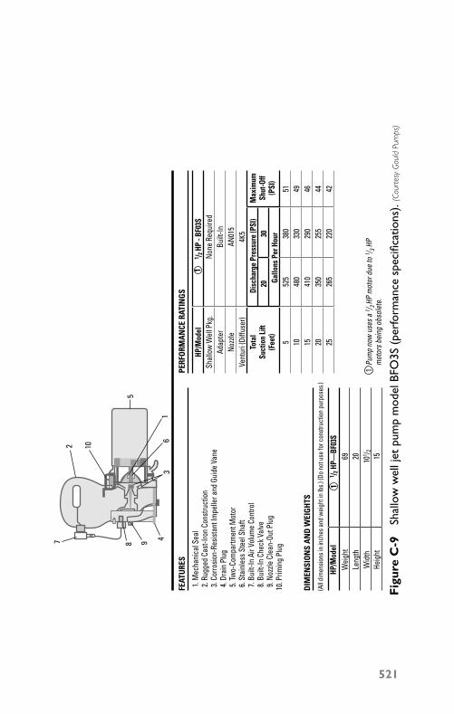
P1: JYC
GB098-AppC GB098-Miller August 11, 2004 11:24 Char Count= 0
FEAT
URE
S
1. M
echa
nica
l Sea
l 2
. Rug
ged
Cast
-Iron
Con
stru
ctio
n 3
. Cor
rosio
n-Re
sista
nt Im
pelle
r and
Gui
de V
ane
4. D
rain
Plu
g 5
. Tw
o-Co
mpa
rtmen
t Mot
or 6
. Sta
inle
ss S
teel
Sha
ft 7
. Bui
lt-In
Air
Volu
me
Cont
rol
8. B
uilt-
In C
heck
Val
ve 9
. Noz
zle C
lean
-Out
Plu
g10
. Prim
ing
Plug
PERF
ORM
AN
CE R
ATIN
GS
DIM
ENSI
ON
S A
ND
WEI
GH
TS
(All d
imen
sions
in in
ches
and
wei
ght i
n lb
s.) (D
o no
t use
for c
onst
ruct
ion
purp
oses
.)
HP/M
odel
Wei
ght
Wid
thHe
ight
Leng
th
1 / 2 HP
—BF
03S
69 101 / 2
1520
1
HP/M
odel
Shal
low
Wel
l Pkg
.No
ne R
equi
red
Adap
ter
Built
-InNo
zzle
AN01
5Ve
ntur
i (Di
ffuse
r)To
tal
Suct
ion
Lift
(Fee
t)
Max
imum
Shut
-Off
(PSI
)
Disc
harg
e Pr
essu
re (P
SI)
20 Gallo
ns P
er H
our30
525
538
051
480
1033
049
410
1529
046
350
2025
544
265
2522
042
4K5
1 / 2 HP
- BF
03S
1
1Pu
mp
now
use
s a 1 / 2 HP
mot
or d
ue to
1 / 3 HP
mot
ors b
eing
obs
olet
e.
2
1
5
63
8 9 4
10
7
Fig
ure
C-9
Shal
low
wel
ljet
pum
pm
odel
BFO
3S(p
erfo
rman
cesp
ecifi
catio
ns).
(Cou
rtes
yG
ould
Pum
ps)
521
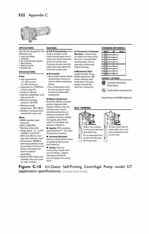
P1: JYC
GB098-AppC GB098-Miller August 11, 2004 11:24 Char Count= 0
522 Appendix C
APPLICATIONSSpecifically designed for the following uses:
Lawn sprinklingIrrigationAir-conditioning systemsHeat pumpsWater transferDewatering•
•••••
Motor:• NEMA standard open
drip proof.• 60 Hz, 3,500 RPM.• Stainless steel shaft.• Single phase: 3/4––11/2 HP,
115/230 V; 2 and 3 HP, 230 V only. Built-in over- load with automatic reset.
• Three phase: 230/460 V. Overload protection must be provided in starter unit. Starter and heaters (3) must be ordered separately.
• Optional TEFC motors are available. See price book for order numbers.
FEATURES Self-Priming Design: Once pump is primed it never needs priming again even if water level drops below the end of the suction pipe. Pumping resumes once the water level rises above the end of the suction pipe.
Serviceable: Back pullout design allows disassembly of pump for service without disturbing piping.
•
• Two compartment motor for easy access to motor wiring and replaceable components.
Diffuser (Guidevane): Bolt down diffuser provides positive alignment with impeller. Diffuser also has stainless wear ring for extended performance in abrasive conditions. FDA compliant, injection molded, food grade, glass filled Lexan for durability and abrasion resistance. Impeller: FDA compliant, glass filled Noryl . Corrosion and abrasion resistant. Corrosion Resistant: Electro-coated paint process is applied inside and out, then baked on. Casing: Cast-iron construction. 4-bolt, back pull-out design. Tapped openings provided for vacuum gauge and casing drain.
Powered for Continuous Operation: Pump ratings are within the motor manu- facturer’s recommended working limits. Can be operated continuously without damage.
Mechanical Seal: Carbon/ceramic faces, BUNA elastomers. 300 series stainless steel metal parts. Exclusive design prevents the seal from running dry.
Water recirculates, but during re-priming operation only.Air is exhausted from suction line through discharge pipe.
Arrows show flow of water after all air has been exhausted fromsuction line.
SELF-PRIMING
STANDARD ODP MODELSModel HP PhaseGT07GT10 1GT15 11/2
11/2
1GT20 2GT30 3
GT073GT103 1GT153 3GT203 2GT303 3
AGENCY LISTINGS
Listed
® Canadian StandardsAssociation
UL® Underwriters Laboratories
Goulds Pumps is ISO 9001 Registered.
SPECIFICATIONS
Pump:• Pipe connections:
11/2" NPT suction 11/2" NPT discharge
• Capacities: to 110 GPM at 5-foot suction lift.
• Heads: to 128 feet.• Reprime capabilities: to 25
feet suction lift.• Maximum working
pressure: 125 PSIG.• Maximum water
temperature: 140°F (60°C).• Rotation: clockwise when
viewed from motor end.
®
®
3/4
3/4
Figure C-10 Irri-Gator Self-Priming Centrifugal Pump model GT(application specifications). (Courtesy Gould Pumps)
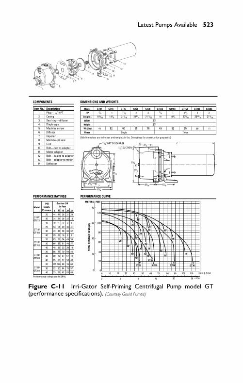
P1: JYC
GB098-AppC GB098-Miller August 11, 2004 11:24 Char Count= 0
Latest Pumps Available 523
COMPONENTS DIMENSIONS AND WEIGHTS
3 4
21
8 13
10
1
11
12
9
7
65
Item No. Description1 Plug – 1/4" NPT2 Casing3 Seal ring—diffuser4 Diaphragm5 Machine screw6 Diffuser7 Impeller8 Mechanical seal9 Foot
10 Bolt—foot to adapter11 Motor adapter12 Bolt—casing to adapter13 Bolt—adapter to motor14 Deflector
11/2" SUCTION
Model5 10 15 20 25
20 44 41 36 31 24
30 34 31 26 22 14
40 10 4 0 0 0
20 53 51 49 46 41
30 43 41 38 36 32
40 29 22 16 8 0
20 63 59 54 49 39
30 60 55 51 46 37
40 45 38 33 20 14
20 86 77 70 59 46
30 80 72 67 57 44
40 65 60 57 50 43
20 105 88 76 60
30 92 90 84 75 57
40 73 67 62 55 50
Performance ratings are in GPM.
Suction Liftin Feet
Model GT07 GT10 GT15 GT20 GT30 GT073 GT103 GT153 GT203 GT303
HP 1 2 11/2 2
Length L 193/16 197/8 213/16 209/16 2111/32 19 193/4 201/16 2013/16 213/16
Width 81⁄4Height 91⁄4Wt (lbs) 48 52 60 65 76 49 52 55 69 71
Phase Single Three
(All dimensions are in inches and weights in lbs. Do not use for construction purposes.)
PERFORMANCE RATINGS PERFORMANCE CURVE
14
PSIDisch.
Pressure
GT10/GT103
GT07/
GT 07
GT 10
GT15 GT20 GT30
GT073
GT15/GT153
GT20/GT203
GT30/GT303
11/2" NPT DISCHARGE
31/2"
31/2
91/4
31/8
49/16 51/878
81/4
L
25'25'
25'
25'
20'20'
20'
20' 20'
15' 15'
15'
15'
15'
10'10'
10'10'
10'
5'
5'
5'5'5'
METERS FEET
3
100
3 1 3
25 '
3/43/411/2
49/16
TOTA
L D
YNA
MIC
HEA
D (H
)
10
20
40
60
80
100
120
20
30
40
0 00
0
10 20 30 40 50 60 70 80 90 100 110 120 U.S.GPM
5 10 15 20 25 m3/hr.
Figure C-11 Irri-Gator Self-Priming Centrifugal Pump model GT(performance specifications). (Courtesy Gould Pumps)
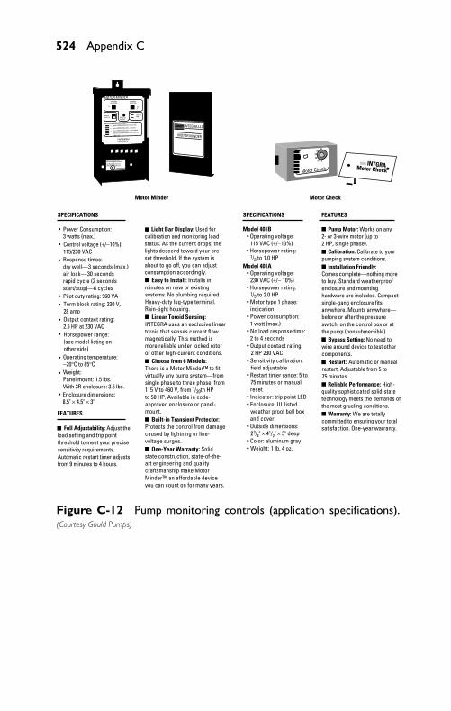
P1: JYC
GB098-AppC GB098-Miller August 11, 2004 11:24 Char Count= 0
524 Appendix C
SPECIFICATIONS
Power Consumption:3 watts (max.)
Model 401B • Operating voltage:
115 VAC (+/−10%) • Horsepower rating:
1/3 to 1.0 HPModel 401A • Operating voltage:
230 VAC (+/− 10%) • Horsepower rating:
1/3 to 2.0 HP • Motor type 1 phase:
indication
Control voltage (+/−10%):115/230 VAC
MOTOR MINDER
MOTOR MINDER
INTEGRA.LLCmxczc:fjhfhkczhijcchhc v,cvcvmj
mxczc:fjhfhkczhijcchhc v,cvcvmj
mxczc:fjhfhkczhijcchhc v,cvcvmjmm
jcjhzchccjczchjccldklclccckcccjkckj
kcjjxjccjcc
hlhxjZcjcnmkxnc`
cbcnckchxjccnc
cbcnckchxj
hjvjkfjkdfksdhjdsifjffjffnf
mbnhsdhsdbzjkkzzxncxczxklc
clvjvjjvkvnjxcnczjjc
clvjvjjvkvnjxcnczjjc
cmjc cm
jc
cjxcchccjcbbchchcczccjcchcgujccjckcxcibvcbjvjvjvjcvcvvvcbckkckjhczhzcjhcxcc
cmvnlnnx
Response times:dry well—3 seconds (max.)air lock—30 secondsrapid cycle (2 secondsstart/stop)—6 cyclesPilot duty rating: 960 VATerm block rating: 230 V,28 ampOutput contact rating:2.5 HP at 230 VACHorsepower range:(see model listing onother side)Operating temperature:−20°C to 85°CWeight:Panel mount: 1.5 lbs.With 3R enclosure: 3.5 lbs.Enclosure dimensions:8.5" × 4.5" × 3"
FEATURES
Full Adjustability: Adjust theload setting and trip pointthreshold to meet your precisesensitivity requirements.Automatic restart timer adjustsfrom 9 minutes to 4 hours.
INTGRAMotor Check
• Power consumption: 1 watt (max.)• No load response time: 2 to 4 seconds• Output contact rating: 2 HP 230 VAC• Sensitivity calibration: field adjustable• Restart timer range: 5 to 75 minutes or manual reset• Indicator: trip point LED
• Color: aluminum gray• Weight: 1 lb, 4 oz.
• Enclosure: UL listed weather proof bell box and cover• Outside dimensions: 23/4" × 41/2" × 3" deep
Motor Check
0204060
80100
SPECIFICATIONS FEATURES
Motor Minder Motor Check
•
•
•
••
•
•
•
•
•
Pump Motor: Works on any2- or 3-wire motor (up to2 HP, single phase). Calibration: Calibrate to yourpumping system conditions.
Warranty: We are totallycommitted to ensuring your totalsatisfaction. One-year warranty.
Reliable Performance: High-quality sophisticated solid-statetechnology meets the demands ofthe most grueling conditions.
Restart: Automatic or manualrestart. Adjustable from 5 to75 minutes.
Bypass Setting: No need towire around device to test othercomponents.
Installation Friendly: Comes complete—nothing moreto buy. Standard weatherproofenclosure and mountinghardware are included. Compactsingle-gang enclosure fitsanywhere. Mounts anywhere—before or after the pressureswitch, on the control box or atthe pump (nonsubmersible).
Choose from 6 Models:There is a Motor Minder™ to fitvirtually any pump system—fromsingle phase to three phase, from115 V to 460 V, from 1/20th HPto 50 HP. Available in code-approved enclosure or panel-mount.
Linear Toroid Sensing:INTEGRA uses an exclusive lineartoroid that senses current flowmagnetically. This method ismore reliable under locked rotoror other high-current conditions.
Easy to Install: Installs inminutes on new or existingsystems. No plumbing required.Heavy-duty lug-type terminal.Rain-tight housing.
Light Bar Display: Used forcalibration and monitoring loadstatus. As the current drops, thelights descend toward your pre-set threshold. If the system isabout to go off, you can adjustconsumption accordingly.
Built-in Transient Protector:Protects the control from damagecaused by lightning or line-voltage surges. One-Year Warranty: Solidstate construction, state-of-the-art engineering and qualitycraftsmanship make MotorMinder™ an affordable deviceyou can count on for many years.
Figure C-12 Pump monitoring controls (application specifications).(Courtesy Gould Pumps)
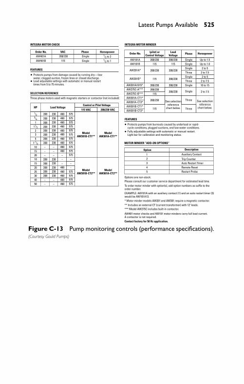
P1: JYC
GB098-AppC GB098-Miller August 11, 2004 11:24 Char Count= 0
Latest Pumps Available 525
INTEGRA MOTOR CHECK
FEATURES
Order No.AW401A 208/230 Single 1/3 to 2
1/3 to 1
1/23/4
11/2
7 1/2
1
2
208
Three phase motors used with magnetic starters or contactor (not included):
Protects pumps from damage caused by running dry—lowwater, clogged suction, frozen lines or closed discharge.Load adjustable settings with automatic or manual restarttimes from 5 to 75 minutes.
230 460 575575575575575575575575575575575
575575575575
460460460460460460460460460
460460460460460
230230230230230230230
230230230230230
208208208208208208208
208208208208208
35
10
10
15
15
20
2520
304050
Single115AW401B
Order No.
AW101AAW101B
AW201A*
AW201B*
AW201A1015*AW275C-A***AW275C-B***AW301A-CT1*AW301A-CT2*AW301B-CT1*AW301B-CT2*
115
115
115
115 115
208/230
208/230208/230
208/230
208/230 208/230 Single Up to 1.5Up to 1.0
2 to 52 to 7.52 to 5
2 to 7.5
2 to 7.5
10 to 15
SingleSingle
Single
Single
Single
Three
Three
Three
Three208/230
208/230
208/230
208/230
See selectionreference
chart below.
See selectionreference
chart below.
Phase HorsepowerLoadVoltage
(pilot) orControl Voltage
HP Load VoltageControl or Pilot Voltage
115 VAC
ModelAW301A-CT1**
ModelAW301B-CT1**
ModelAW301A-CT2**
ModelAW301B-CT2**
208/230 VAC
VAC Phase Horsepower
SELECTION REFERENCE
INTEGRA MOTOR MINDER
FEATURES
Option
1 Auxiliary Contact2 Trip Counter3 Auto Restart Timer4 Remote Reset5
Options are non-stock.Please consult our customer service department for estimated lead time.To order motor minder with option(s), add option numbers as suffix to theorder number.EXAMPLE: AW101A with an auxiliary contact (1) and an auto restart timer (3)would be AW101A13.* Motor minder models AW201 and AW301 require a magnetic contactor.** Includes an external CT (current transformer) with 12" leads.*** Model AW275C includes built-in contactor.
AW401 motor checks and AW101 motor minders carry full load current.A contactor is not required.Contact factory for 50 Hz application.
Restart Probe
Description
MOTOR MINDER ”ADD-ON OPTIONS“– –
––––
––
––
––
––
––
Protects pumps from burnouts caused by underload or rapid-cycle conditions, plugged suctions, and low water conditions.Fully adjustable settings with automatic or manual restart.Light bar for calibration and monitoring status.
Figure C-13 Pump monitoring controls (performance specifications).(Courtesy Gould Pumps)
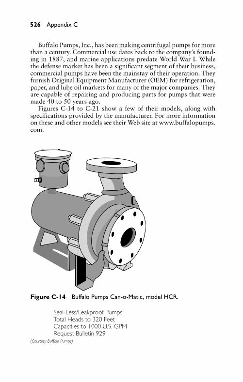
P1: JYC
GB098-AppC GB098-Miller August 11, 2004 11:24 Char Count= 0
526 Appendix C
Buffalo Pumps, Inc., has been making centrifugal pumps for morethan a century. Commercial use dates back to the company’s found-ing in 1887, and marine applications predate World War I. Whilethe defense market has been a significant segment of their business,commercial pumps have been the mainstay of their operation. Theyfurnish Original Equipment Manufacturer (OEM) for refrigeration,paper, and lube oil markets for many of the major companies. Theyare capable of repairing and producing parts for pumps that weremade 40 to 50 years ago.
Figures C-14 to C-21 show a few of their models, along withspecifications provided by the manufacturer. For more informationon these and other models see their Web site at www.buffalopumps.com.
Figure C-14 Buffalo Pumps Can-o-Matic, model HCR.
Seal-Less/Leakproof PumpsTotal Heads to 320 FeetCapacities to 1000 U.S. GPMRequest Bulletin 929
(Courtesy Buffalo Pumps)
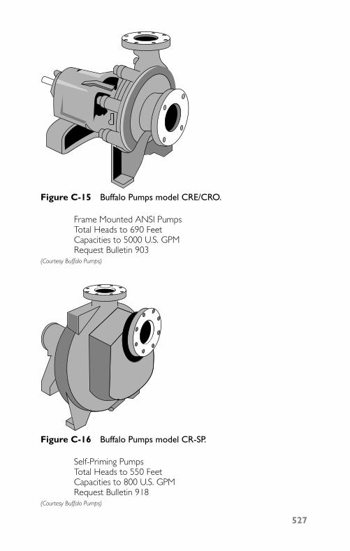
P1: JYC
GB098-AppC GB098-Miller August 11, 2004 11:24 Char Count= 0
Figure C-15 Buffalo Pumps model CRE/CRO.
Frame Mounted ANSI PumpsTotal Heads to 690 FeetCapacities to 5000 U.S. GPMRequest Bulletin 903
(Courtesy Buffalo Pumps)
Figure C-16 Buffalo Pumps model CR-SP.
Self-Priming PumpsTotal Heads to 550 FeetCapacities to 800 U.S. GPMRequest Bulletin 918
(Courtesy Buffalo Pumps)
527
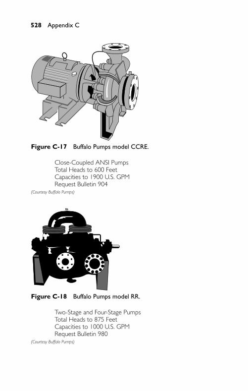
P1: JYC
GB098-AppC GB098-Miller August 11, 2004 11:24 Char Count= 0
528 Appendix C
Figure C-17 Buffalo Pumps model CCRE.
Close-Coupled ANSI PumpsTotal Heads to 600 FeetCapacities to 1900 U.S. GPMRequest Bulletin 904
(Courtesy Buffalo Pumps)
Figure C-18 Buffalo Pumps model RR.
Two-Stage and Four-Stage PumpsTotal Heads to 875 FeetCapacities to 1000 U.S. GPMRequest Bulletin 980
(Courtesy Buffalo Pumps)
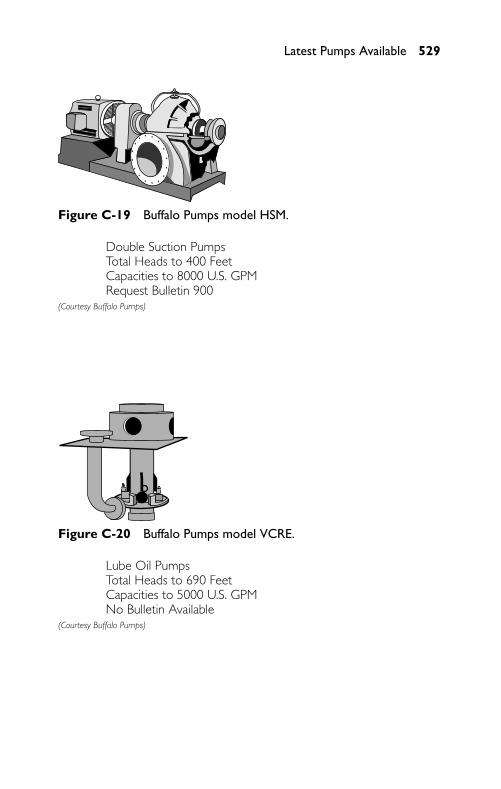
P1: JYC
GB098-AppC GB098-Miller August 11, 2004 11:24 Char Count= 0
Latest Pumps Available 529
Figure C-19 Buffalo Pumps model HSM.
Double Suction PumpsTotal Heads to 400 FeetCapacities to 8000 U.S. GPMRequest Bulletin 900
(Courtesy Buffalo Pumps)
Figure C-20 Buffalo Pumps model VCRE.
Lube Oil PumpsTotal Heads to 690 FeetCapacities to 5000 U.S. GPMNo Bulletin Available
(Courtesy Buffalo Pumps)
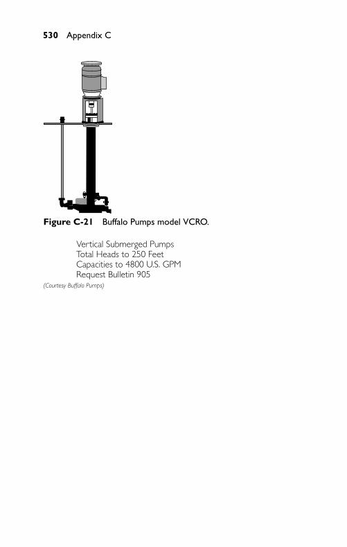
P1: JYC
GB098-AppC GB098-Miller August 11, 2004 11:24 Char Count= 0
530 Appendix C
Figure C-21 Buffalo Pumps model VCRO.
Vertical Submerged PumpsTotal Heads to 250 FeetCapacities to 4800 U.S. GPMRequest Bulletin 905
(Courtesy Buffalo Pumps)
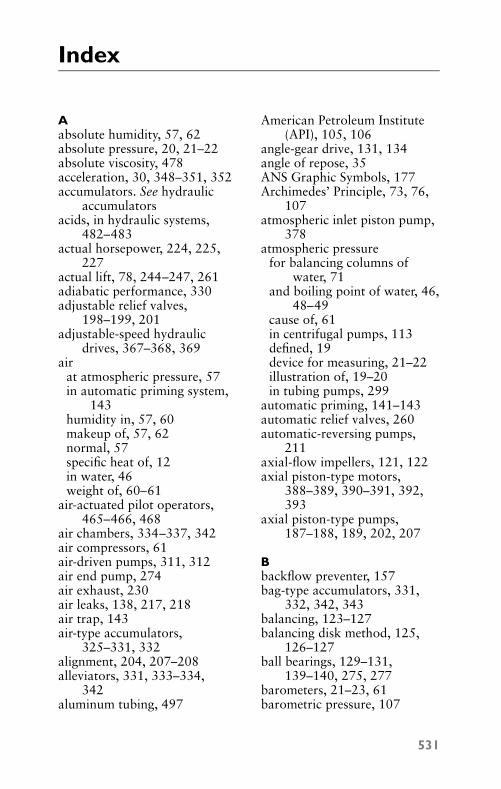
P1: FCH
GB098-ind GB098-Miller September 21, 2004 17:57 Char Count= 0
Index
Aabsolute humidity, 57, 62absolute pressure, 20, 21–22absolute viscosity, 478acceleration, 30, 348–351, 352accumulators. See hydraulic
accumulatorsacids, in hydraulic systems,
482–483actual horsepower, 224, 225,
227actual lift, 78, 244–247, 261adiabatic performance, 330adjustable relief valves,
198–199, 201adjustable-speed hydraulic
drives, 367–368, 369air
at atmospheric pressure, 57in automatic priming system,
143humidity in, 57, 60makeup of, 57, 62normal, 57specific heat of, 12in water, 46weight of, 60–61
air-actuated pilot operators,465–466, 468
air chambers, 334–337, 342air compressors, 61air-driven pumps, 311, 312air end pump, 274air exhaust, 230air leaks, 138, 217, 218air trap, 143air-type accumulators,
325–331, 332alignment, 204, 207–208alleviators, 331, 333–334,
342aluminum tubing, 497
American Petroleum Institute(API), 105, 106
angle-gear drive, 131, 134angle of repose, 35ANS Graphic Symbols, 177Archimedes’ Principle, 73, 76,
107atmospheric inlet piston pump,
378atmospheric pressure
for balancing columns ofwater, 71
and boiling point of water, 46,48–49
cause of, 61in centrifugal pumps, 113defined, 19device for measuring, 21–22illustration of, 19–20in tubing pumps, 299
automatic priming, 141–143automatic relief valves, 260automatic-reversing pumps,
211axial-flow impellers, 121, 122axial piston-type motors,
388–389, 390–391, 392,393
axial piston-type pumps,187–188, 189, 202, 207
Bbackflow preventer, 157bag-type accumulators, 331,
332, 342, 343balancing, 123–127balancing disk method, 125,
126–127ball bearings, 129–131,
139–140, 275, 277barometers, 21–23, 61barometric pressure, 107
531
P1: FCH
GB098-ind GB098-Miller September 21, 2004 17:57 Char Count= 0
532 Index
base plates, 135, 204basic machines, 38, 40–46Baume scale hydrometers,
105–106bearing carriers, 197–198bearings, 129–131, 143, 149,
265, 415, 428. See also ballbearings
bedplates, 199, 203belt-drive pumps, 132bleed-off method, 443–444blind-end cover, 408blind-end flange mountings,
420boiler-feed pump, 81boiler horsepower, 39boilers, 50, 51, 53, 170brake horsepower, 39British thermal unit (Btu),
10–11buoyancy, 73–77, 107bypass lines, filters in, 484
Ccam-roller operators, 463–465cam-type operators, 453–454cases, 114casings, 127, 128, 149–150,
173, 266, 269cast-type manifolds, 505CCS systems, 378–380Celsius thermometers, 9centerline-mounted hydraulic
cylinders, 420–421center of buoyancy, 74, 107center of gravity, 23, 24centrifugal force, 23–24
defined, 113diagram of, 114, 116in hydraulic drives, 347–348,
349, 381in pumps (see centrifugal
pumps)
in vane-type pumps, 182, 184centrifugal pumps
abnormal operatingconditions for, 146,148–149
assembly of, 150–152balancing, 123–127base plate of, 135basic designs of, 118bearings for, 129–131calculations applicable to,
162–164casing for, 127causes of problems in, 147characteristics of, 259checking alignment of, 136for chemical and paper
industries, 270–273close-coupled, 267, 270cooling water piping for,
139–140corrosion-resistant, 152–162coupling bolts for, 135with curved vanes, 114–115,
116cutting into lines, 144deep-well adjustments in, 151diagram of parts of, 114, 115discharge piping for, 138double-inlet type of, 127, 173drives for, 131–133, 134dry-pit non-clog, 267, 269efficiency of, 120, 174electrical hook-up for, 156essential parts of, 114flowing oil to bearing surfaces
in, 143foundation for, 135functioning of, 113gages on, 173general care of, 148glass, 273grouting, 137
P1: FCH
GB098-ind GB098-Miller September 21, 2004 17:57 Char Count= 0
Index 533
handling difficulties inoperation of, 148–149
for handling solids, 267, 269head of, 259height of lift of, 135and high-temperature liquids,
138–139horizontal end-suction, 271,
272horizontal-type, 279housing for, 127, 128idle state of, 146impellers in (see impellers)increasing pressure of, 118inlet piping for, 137–138installation of, 133, 135–139installing increaser on
discharge lines of, 151lateral end clearances in, 149leveling, 135–137lift of, 259locating, 133, 135locking screws for, 150–151maintenance of, 149–152major parts of, 117multistage, 119–120,
173–174operating principle of, 23–24operation of, 139–146parts renewals for, 149–150portable, 118–119power cord of, 156priming, 140–143, 174providing minimum end thrust
in, 126purposes for, 118receiver in, 113repair of, 149–152rotating member in, 113running without liquid, 174self-priming, 266, 268, 313for sewage, 275shaft assembly for, 131
single-stage, 118–119, 173,266, 269
speed of, 259, 260stages in, 119–120starting, 143–145stationary-mounted, 119stopping, 145–146with straight vanes, 114, 116stuffing-box assembly for,
129, 130symptoms of leaks in, 148troubleshooting problems in,
146–149uses of, 313variations of pressure in, 126vibration in, 146, 148for viscous fluids, 152–162volute, 114–118water-seal cage of, 145
centripetal force, 24–25charging valves, 400, 401, 402check valves, 140, 141, 157,
446, 457chemical and process pumps,
270–273, 302–309chemicals, materials for
handling, 302–309circuits
for atmospheric inlet pistonpumps, 378, 379
hydraulic, 383, 385–394for hydraulic accumulators,
338–342, 343hydraulically controlled,
394–402for hydrostatic transmission
systems, 360–361for pumps, 226
closed-diaphragm pumps,282–283
coefficient of friction, 35coefficient of linear expansion,
14
P1: FCH
GB098-ind GB098-Miller September 21, 2004 17:57 Char Count= 0
534 Index
combination pumps, 394–395components of force, 27–28compressors, 326conduction, 11–12, 13conservation of energy, 5–7constant-displacement motors,
385–386, 388–391, 392constant-displacement pumps,
399, 402constant motion, 32contaminants, sources of, 482–483contraction, 14control valves
categories of, 435, 450charging-valve, 400for combination pump, 394for constant-displacement
pumps, 402determining size of, 435directional, 447–450electrical solenoid-operated
directional, 399five-way directional, 450flange-type connections on,
435, 437, 438for flow control, 435,
441–447, 454–456, 457four-way directional, 400,
401, 448, 459, 462function of, 435heat-treated, 436materials for, 435–436neutral, 400operators for (see valve
operators)packing for, 436, 450pilot-operated directional, 399for pressure control, 435,
437–441, 442, 443,453–454, 455
pressure-regulating, 399–400pressure-relief, 401pressures handled by, 450remote directional, 395–397
slow-feed, 400–401spool configurations of, 449sub-plate mountings for, 435,
436termite effect in, 436three-way directional,
447–448two-way directional, 447, 448for variable-displacement
pumps, 402wire-drawing effect in, 436
convection, 12, 13, 14cooling, by re-evaporation,
51–53, 54cooling water, 139copper tubing, 497corrosion-resisting centrifugal
pumps, 152–162corrosive liquids, 296counterbalance valves, 440–441coupling bolts, 135couplings
attaching to hoses, 500–501clearance between faces of, 137flexible, 204for hoses, 502, 503–504quick-disconnect, 503–504,
505cover bolts, 424cover gaskets, 415cover screws, 411cushion-adjustment valve, 413,
415cushion collars, 413–415,
418–419cushion nose, 413–415cylinder covers, 408, 426cylinder tubes, 408, 411
Ddeep-well pumps, 287, 288–295deformation thermometers, 8degrees API, 109density, 103, 104
P1: FCH
GB098-ind GB098-Miller September 21, 2004 17:57 Char Count= 0
Index 535
detents, 459, 461diaphragm-type accumulator,
331, 332diaphragm-type pumps,
282–287differential hoist, 42direct-acting pilot operators,
465–468direct-acting solenoids, 460,
462direct-acting valves, 437, 439,
440direct-drive pumps, 132directional controls, 447–450
function of, 435hand-type operator for, 458knee-type operators for, 458manual operators for, 456,
458–460, 461–462mechanical operators for,
463–465pilot operators for, 465–468solenoid operators for, 460,
462–463spring-centered, 459, 460–461spring-offset, 459stem-operated, 458
direct-operated pilotpressure-relief valves, 438
direct-type accumulators, 319,320–322
discharge head, 164discharge piping
for centrifugal pumps, 138friction loss in, 222–223installing increaser on,
151–152nominal size of, 261required size for reciprocating
pumps, 248restrictive devices in, 212for rotary pumps, 209, 210
discharge valves, 141, 144,236–237, 282–283, 334
displacement, 72–73, 107,250–252, 255, 261,322–323
distributor body, 427–428double-acting force pumps,
236–239, 240, 251, 252,261
double-acting nonrotatingcylinders, 405, 407, 432
double-admission impellers,123–124
double-admission pumps, 118,119, 123–125
double-solenoid valves, 462double-stage pumps, 185–186dowels, 138draft, 72–73, 107drain piping, 139drilled-type manifolds, 505drive pins, 427drivers, 139, 147, 348, 356drives, 131–133, 134, 136, 137,
208. See also hydraulicdrives
drive shafts, 197driving pumps, 208–209dry-well installations, 275dynamic column, 221–223dynamic head, 68, 69, 77–78,
84, 86, 107, 222–224, 248dynamic inertia, 34, 349–350dynamic lift, 68–69, 70, 78–79,
80, 82, 84, 86, 107–108,221–222, 249
dynamic total column, 84, 86,108
dynamic viscosity, 478, 480Dynapower transmission
systems, 362–365, 381
Eeccentric loading, 421–422efficiency, of pumps, 254–260ejector method, 140–141
P1: FCH
GB098-ind GB098-Miller September 21, 2004 17:57 Char Count= 0
536 Index
ejector pumps, 257, 259, 260electrical horsepower, 39electrical thermometers, 8electric motors, 208–209electric power failure,
340–341enclosed-type impellers, 121,
122, 129, 130, 174, 275end-bell mounted pumps, 199,
204end covers, 196–197end thrust, 126–127energy, 5–7, 36, 61entry head, 78equilibrium, 20, 24–25, 38,
40, 47–48, 50–51,76–77
evaporation, 82exhaust line, filters in,
484–485expansion, 14, 56extruded tubing, 302–305
Ffabricated-tube manifolds, 505Fahrenheit, Gabriel Daniel, 8Fahrenheit thermometers, 8–9farm tractors, hydraulic
transmissions for, 368–371,372
faucets, friction loss in, 85, 87feeler gage, 136filters, 375, 482–487First Law of Motion, 29fittings, 124–125, 155,
495–496, 502, 504five-stage pumps, 124–125five-way directional control
valves, 450fixed-displacement motors,
360–362, 391, 393fixed-displacement pumps,
361–362
fixed pulleys, 42flange gaskets, 150flange-mounted hydraulic
cylinders, 419–420flange-type connections, 435,
437, 438flexible coupling, 204flexible piping, 499–505float-controlled automatic
priming system, 141–142float switch, 141, 142flow controls, 435, 441–447,
454–456, 457fluid drives, 352–353, 355, 356.
See also hydraulic drivesfluidity, 478fluid lines, 491–505, 506, 507fluid power pumps, 196–197fluids
calculating dischargedquantities of, 95–96
controlling flow of, 435,441–447, 454–456, 457
defined, 3in diaphragm pumps, 284,
285displaced, 72–73handled by reciprocating
pumps, 240, 242hydraulic (see hydraulic fluids)in hydraulic cylinders, 413,
414, 432in hydraulic torque converters,
358–359in rubber impeller pumps,
296–297, 299follower disks, 353foot-mounted hydraulic
cylinders, 421foot-mounted pumps, 199, 203foot-pound (ft-lb), 36–37foot-valve method, 141–143force, 26–28, 42–46, 415–418
P1: FCH
GB098-ind GB098-Miller September 21, 2004 17:57 Char Count= 0
Index 537
force pumps, 3, 231, 233–239,260–261, 318
foundations, for centrifugalpumps, 135
four-stage pumps, 270, 272four-way directional control
valves, 400, 401, 448, 450,459, 462
Francis formula, 92free air, 57friction
calculating, 219–220calculating loss of pressure
from, 85–89, 90–91causes of, 34coefficient of, 35defined, 34in faucets, 85, 87for imperfect lubrication,
35–36laws of, 35–36loss of head due to, 90,
165–168minimizing, 244for perfect lubrication, 35of water in pipes, 84–89,
90–91, 108friction head, 78fulcrum, 40, 75fumes, removal of, 155fume scrubbers, 155fusion, 4
Ggage pressure, 20–21gages, on centrifugal pump, 173gases, pressure change of, 330gaskets, 423, 427gasoline engines, 209gas-type accumulators,
325–331, 332gears, 178–181, 389gear-type motors, 389
gear-type pumpsadjustable relief valves for,
198–199, 201applications of, 265–266, 267,
268bearing carrier for, 197–198bronze, 213, 214cast-iron, 213, 214classification of, 225construction of, 190–199,
200, 201, 202, 203–204,205
delivery rate of, 177description of, 177direction of rotation in,
210–211discharge from, 212drives for, 208drive shafts for, 197efficiency of, 177end covers for, 196–197external type of, 179gear housings for, 190, 191gears used for, 178–180hydrostatic, 376–377installation of, 212–213internal type of, 179, 180, 181liquids handled by, 190–196,
265, 267materials used for, 191–196mechanical seal for, 198, 200mounting, 199, 202, 203–204movement of liquid through,
178packed box, 198pressure-relief valves for,
215–216for pumping viscous liquids,
214–215ratings for, 177shaft seal for, 198, 199stainless steel, 214, 215steam chest for, 198, 201
P1: FCH
GB098-ind GB098-Miller September 21, 2004 17:57 Char Count= 0
538 Index
gear-type pumps (continued)strong points of, 190suction in, 212, 213types of, 213–216uses of, 312volumetric efficiency of,
190Gerotor mechanism, 179,
181–182glass pumps, 273, 313graphite-type packing, 144gravity, 22–25, 61, 76–77,
102–106grouting, 137
Hhand pumps, 311, 342hand-type operators, 458head, 68, 69
calculating for reciprocatingpumps, 248–249
of centrifugal pumps, 259converting pressure (psi) to,
224converting to pressure (psi),
223discharge, 164dynamic, 68, 69, 77–78, 84,
86, 107, 222–224, 248entry, 78friction, 78generated by impeller, 118loss due to friction, 90,
165–168points of measurement for, 69of reciprocating pumps, 259static, 68, 69, 70, 84, 85,
106–107, 222, 248–249suction, 79, 80velocity, 78, 164, 169–170
heat, 7–14, 61heat-resistant packing, 422heat transfer, 11–14
helical-gear pumps, 180,182–183, 211
herringbone-gear pumps, 180,183
herringbone gears, 389high-temperature liquids,
138–139hook gage, 91, 93horsepower (hp)
actual versus theoretical, 227calculating required amount
of, 224–225defined, 37formula for, 37–38increases for pumping viscous
liquids, 215origin of, 37required for given pump
capacity, 256–257, 258for rotary pumps, 224–225types of, 38, 39
hose pipes, 306–309, 499–505,506
hot-condensate pumps, 145hot-water heating systems,
50–51, 53housings, 119–120, 127, 128,
173, 190, 191humidity, 57, 60hydraulic accumulators
air chambers in, 334–335,336–337, 342
air-type, 324–331, 332circuits for, 338–342, 343energy stored in, 317function of, 317intensifiers in, 323–324operation of, 317–318parts of, 317, 318as power-saver, 338–339,
340as pressure booster, 323–324,
342
P1: FCH
GB098-ind GB098-Miller September 21, 2004 17:57 Char Count= 0
Index 539
protection against waterhammer in, 331, 333–338
for reserve power supply,340–341
as shock absorbers, 331,333–334, 338, 339
sizing table for, 328–329spring-loaded, 324, 325types of, 318vacuum chambers in, 335,
337–338, 342, 344water flow in, 317, 318weight-loaded, 319–324
hydraulically controlledcircuits, 394–402
hydraulic balance, 199–200,206
hydraulic circuits, 383,385–394, 396, 398–403
hydraulic cylinderscontrolling flow in, 443–444covers for, 408fluid in, 432with foot-mounted covers,
424function of, 405internal view of, 418nonrotating (see nonrotating
cylinders)piston assembly in, 411, 412“push and pull” force chart
for, 416–417rotating (see rotating
cylinders)tie rods for, 411types of, 405
hydraulic drivesadjustable-speed, 367–368,
369for braking, 373CCS systems, 378–380centrifugal force in, 347–348,
349
circulation of oil in, 347–352displacement-type
transmission, 359–367,381
farm tractor applications of,368–371, 372
filters for, 375fluid, 352–353, 355–356function of, 345–346hydrostatic pumps for,
376–377leaks in, 375–376operating principles of,
346–348, 349parts of, 346, 381pioneer type of, 346piston-type rotary devices in,
377–378power in, 347pressure applied to, 375pressure build-up in, 375for robots, 373–376rotating members in, 356, 357tangential acceleration in,
348–351, 352tangential deceleration in,
351–352, 353, 354torque converters, 358–359,
360twin-disk, 357–358
hydraulic efficiency, 255hydraulic filters, 482–487hydraulic fluids
additives for, 488carriers for (see fluid lines)categories of, 473, 488changing in hydraulic systems,
476–477contamination of, 481–482dynamic viscosity of, 488excessive velocities of, 435filters for, 482–487fire-resistant, 473–474
P1: FCH
GB098-ind GB098-Miller September 21, 2004 17:57 Char Count= 0
540 Index
hydraulic fluids (continued )flow of, 435fluidity of, 478functions of, 473, 477, 488lubricating value of, 481maintenance of, 475–476oxidation of, 481–482petroleum-base, 473pour point of, 481quality requirements for,
474selecting, 477–482shearing action in, 478specific weight of, 477synthetic-base, 473–474testing viscosity of, 479in torque converter,
358–359viscosity of, 478–481
hydraulic horsepower, 39hydraulic load, 164, 169–170hydraulic motors, 376
changing speed of, 403classifications of, 403constant-displacement, 385,
386, 388function of, 383gear-type, 389in hydraulic circuit, 383,
385–394piston-type, 390–394vane-type, 390variable-displacement,
385–386, 388–389by Vickers, 391, 393
hydraulic oilchanging in hydraulic systems,
476–477checking, 475circulation in hydraulic drives,
347–352in constant-displacement
motors, 386, 388contamination of, 481–482
draining, 475dynamic inertia of, 349–350in Dynapower transmission
system, 363fluidity of, 478in gear-type pumps, 177–178lubricating value of, 481maintenance of, 475–476mixing, 475oxidation of, 481oxidation stability of, 482pour point of, 481properties of, 474quality requirements for, 474in robot drive systems,
373–374selecting, 477–482specific weight of, 477storage of, 475and tangential acceleration,
348–351, 352testing viscosity of, 479types of, 473in variable-displacement
motor, 391viscosity of, 478–481
hydraulic pressure, 182, 184,320, 321–322, 374–376
hydraulic pumps, 383, 387,394–395
hydraulicsbasic principles of, 65–69,
106defined, 65, 106drives for (see hydraulic
drives)head of, 68, 69hydrodynamics, 77–84,
84–89, 90–91, 107hydrostatics, 69–75, 106lift of, 68systems of (see hydraulic
systems)water flow (see water flow)
P1: FCH
GB098-ind GB098-Miller September 21, 2004 17:57 Char Count= 0
Index 541
hydraulic sequence valves,438–439, 440
hydraulic shock absorber, 331,333–334
hydraulic shocks, 331,333–338
hydraulic systemsacids in, 482–483changing fluids in, 476–477cleaning, 475–476, 485control valves for (see control
valves)cylinder in (see hydraulic
cylinders)filters for, 482–487handling shocks in, 333–338hoses for, 499–505, 506maintenance of oil for,
475–476manifolds for, 505, 507mobile-type filter units for,
485–487piping for (see fluid lines)for power chucking, 397problems with viscosity of
hydraulic fluids in, 480rust in, 482selecting fluids for, 477–482sludge in, 482–483sources of contaminants in,
482–483tubing fittings for, 495–496undesirable quantities of air
in, 481–482wear in, 482
hydraulic torque converters,358–359, 360
hydraulic valves, 449hydrodynamics, 77–84, 84–89,
90–91, 107hydrometers, 57, 104–106, 108hydrostatic balance, 76–77hydrostatic paradox, 76, 107hydrostatic pumps, 376–377
hydrostatics, 69–75, 106hydrostatic transmission
systems, 359–367, 381hydrostats, 445–447
Iimpellers
axial-flow type of, 121, 122checking rotation of, 161for chemical and process
pumps, 271in corrosion-resisting pumps,
161curvature of vanes of, 117deep-well adjustments of, 151design considerations for,
162–164, 169–170direction of liquids through,
125double-admission, 118–119efficiency of, 120enclosed type of, 121, 122,
129function of, 113, 173head generated by, 118importance of, 127lift of, 164linking together in one system,
118mixed-flow type of, 121–123for natural balancing,
123–125open type of, 121, 129opposed, 150preventing foreign material in,
138in rubber impeller pumps,
297semi-open, 120for sewage, 275single-admission, 118, 119single-vane, 120–121tightening, 150types of vanes on, 174
P1: FCH
GB098-ind GB098-Miller September 21, 2004 17:57 Char Count= 0
542 Index
impellers (continued )and velocity head, 164,
169–170velocity of, 163–164
imperfect lubrication, 35–36inboard guide bearing, 130inclined planes, 43–44increasers, 151inertia, 3, 34inlet head, 164inlet piping, 137–138, 217,
218, 244, 246–247inlet valves, 236–237, 282–283intake line, filters in, 484, 485intensifiers, 323–324internal combustion engines,
209inverted-type accumulators,
319–321irrigation pumps, 281–282isothermal performance, 330
Jjacket piping, 139jets, 98–101jet-type pumps, 287, 289Joule’s equivalent, 6–7
Kkinetic energy, 5, 351–352, 353
Llatent heat, 9–10laws of friction, 35–36leveling, 135–137levers, 40–41lift, 68–69
actual, 244–247converting vacuum gage
reading to, 172of impellers, 164, 169–170negative, 164points of measurement for, 69,
70
of reciprocating pumps,243–247
static, 70symptoms of excessively high,
216, 217theoretical, 243–244at various temperatures and
altitudes, 245lift pump method, 141lift pumps, 78–79, 80,
230–231, 232, 260, 277,278
lift stations, 274–275, 278line strainers, 212, 213liquid drives. See hydraulic
drivesliquid-ring pumps, 273, 274liquids
buoyancy of, 73–75causes of inadequate delivery
of, 216–217handled by gear-type pumps,
190–196high-temperature, 138–139in nonseparator-type
accumulator, 325–326open vanes for, 121packing for, 144, 145requiring special type of
pumps, 265in rubber impeller pumps,
296–297, 299shearing action of, 478in single-admission pumps,
125–126specific gravity of, 103–104specific heat of, 12specific weight of, 477in spur-gear pumps, 179testing viscosity of, 479in turbine pumps, 295–296viscosity chart for, 152
load, relation to force, 32–43locking screws, 150–151
P1: FCH
GB098-ind GB098-Miller September 21, 2004 17:57 Char Count= 0
Index 543
lubricating values, 481lubrication
for corrosion-resistingcentrifugal pumps, 157
imperfect, 35–36perfect, 35of rotating cylinders, 430for tubing pumps, 301
Mmachine tools, 398, 399magma pumps, 276, 313maintenance
of centrifugal pumps, 149–152of corrosion-resisting
centrifugal pumps, 157of hydraulic oil, 475–476of nonrotating cylinders,
423–424of rotating cylinders, 430–432
manifolds, 505, 507manifold-type mountings, 435,
436manual-type operators, 456,
458–460, 461–462matter, 3–4mechanical balancing, 125–127mechanical efficiency, 255–256mechanical operators, 463–465mechanical powers, 38, 40–46mechanical seal, 198, 200medical pumps, 273–274mercury, 12, 21metallic scraper, 410metals
heat conductivity of, 13linear expansion of, 15specific heat of, 12used for gear-type pumps,
191–196meter-in method, 443–444meter-out method, 443–444mill-type cylinders, 408, 409mineral oils, 473
mixed-flow impellers,121–123
mobile-type filter units,485–487
moisture, effect on aircompressors, 61
moment, 75momentum, 33–34motion, 61–62
acceleration, 30apparent versus actual,
29, 30constant, 32defined, 28and inertia, 34and momentum, 33–34Newton’s laws of, 29–30oscillating, 31, 32reciprocating, 31–32resistance to (see friction)tangential, 30–31types of, 30variable, 32, 33velocity, 30
motor drives, 137motors
constant-displacement, 385,386, 388
direction of rotation in, 211in Dynapower transmission
system, 365fixed-displacement, 360–362hydraulic (see hydraulic
motors)internal combustion engines,
209pressure-compensated control
of, 365for rotary pumps, 208–209selecting, 209for submersible pump, 294for sump pumps, 277, 280symptoms of problems with,
159
P1: FCH
GB098-ind GB098-Miller September 21, 2004 17:57 Char Count= 0
544 Index
motors (continued )variable-displacement,
361–362mounting brackets, 199, 203movable pulleys, 42–43multistage pumps, 119–120,
123–125, 138, 139, 173multi-tube pumps, 311–312
Nnatural balancing, 123–125needle valves, 444, 445negative lift, 79, 80negative slip, 253neutral control valves, 400,
401, 402Newton’s laws of motion,
29–30nominal horsepower, 39non-clogging pumps, 274noncompensating-type flow
controls, 444–445, 446noncontraction jets, 98nonrotating cylinders
applications for, 406causes of failure in, 422–423centerline-mounted, 420–421center support for, 421checking for leaks in, 424cleaning, 423cover gaskets for, 415covers for, 408cushion-adjustment valve for,
413, 415cushion collar and nose for,
413, 414, 418–419dismantling, 423double-acting, 405, 407flange-mounted, 419–420foot-mounted, 421with foot-mounted covers,
424forces in, 415–418, 432
high-pressure designs of, 418installation of, 418–422, 432loading, 421–422mill-type, 408, 409misalignment in, 422–423parts of, 407–415piston assembly in, 411, 412piston-rod bearing for, 415piston rod in, 408ram-type, 405, 407reassembly of, 423–424repair and maintenance of,
423–424rod packing for, 415rod wiper in, 408, 410single-acting, 405, 407testing, 424threaded-tube construction of,
418–419tie rods for, 411tube for, 408, 411types of, 405
nonseparator-type airaccumulator, 325–326
normal air, 57nylon tubing, 497
Oodors, removal of, 155oil
in diaphragm pumps, 284in gear-type pumps, 177–178lubricating with, 161oxidation stability of, 482specific gravity of, 105types of, 473in vane-type motor, 390See also hydraulic oil
oil-less pumps, 274oil-lubricated pumps, 273oil-sealed pumps, 274oil shaft stem, 427open-diaphragm pumps, 284
P1: FCH
GB098-ind GB098-Miller September 21, 2004 17:57 Char Count= 0
Index 545
open-type impellers, 121, 129operating signals, 441, 442, 443opposed impellers, 150opposing-impellers method,
123orifices, flow of water through,
97–102origin of moments, 75O-rings, 160, 375, 419oscillating-type engine, 32outboard thrust bearing, 130oxidation, 481–482
Ppacking glands, 144, 148, 198,
199, 412packings
for control valves, 436, 450deterioration of, 422for gear-type pumps, 198, 199for high temperatures, 144,
145inside, 237, 238for liquid, 144, 145outside, 237, 239, 240for piston rods, 415in reciprocating pump, 229in rotating cylinders, 427–428
paper mills, pumps for,270–273
parabola, 99–101parallelogram-of-forces
method, 27partial vacuum, 20Pascal, Blaise, 65pascals, 374perfect lubrication, 35perfect vacuum, 20periphery pumps. See turbine
pumpspetcocks, 335petroleum-base fluids, 473, 476physics
of bodies, 4–5centrifugal force, 23–24centripetal force, 24–25conservation of energy, 5–6defined, 3of energy, 5–7of force, 26–28of friction, 34–36of gravity, 22–25of heat, 7–14of hydraulics (see hydraulics)of matter, 3–4of motion, 28–34of pressure, 14–21of work and power, 36–38
pilot-operated directionalcontrol valves, 401, 402
pilot-type valve operators,465–468
pilot-type valves, 439, 440pipelines, 401–402. See also
pipingpiping
calculating friction of waterin, 219
calculating required diameterof, 244, 246–247
categories of, 507drain, 139entry head for, 78flexible, 499–505, 506friction head for, 78friction of water in, 84–89,
90–91for hydraulic fluid (see fluid
lines)independent supports for, 152installation of, 498–499jacketed, 139loss of head due to friction in,
165–168minimizing friction in, 244for priming, 142–143, 144
P1: FCH
GB098-ind GB098-Miller September 21, 2004 17:57 Char Count= 0
546 Index
piping (continued )for pump discharge (see
discharge piping)for pump inlets, 137–138,
217, 218, 244, 246–247quantity of water discharged
through, 89replacing with manifolds, 505,
507rigid, 491–492, 493for rotary pumps, 209–210semi-rigid, 492, 494–499sizes of, 492, 493steel, 491–492, 493types of, 497velocity head for, 78
piston-rod bearings, 415piston rods, 408, 423, 426, 431pistons
assembly of, 411, 412bucket-type valve in, 235calculating displacement of,
250calculating speed of, 251–252in combination pumps, 395in constant-displacement
motors, 388for double-acting force
pumps, 236–237effect of dirt particles on,
422functions of, 426intake and discharge stroke of,
231in lift pump, 231, 232locknut for, 411in nonrotating cylinders, 411,
412in piston-type pumps,
187–188, 189versus plungers, 229, 230in reciprocating pump, 229,
230, 261in rotating cylinders, 426
in separator-type airaccumulators, 326–327
in single-acting nonrotatingcylinders, 405, 407
speed of, 261–262transfer stroke of, 231in variable-displacement
motors, 388–389piston speed, 251–252,
261–262piston-type accumulator,
326–327, 330piston-type motors, 388–394piston-type pumps, 187–188,
189, 225axial, 202, 207charging with oil, 400construction of, 200, 202,
206–207in hydraulic systems, 377–378radial, 200, 202, 206rotary devices of, 377uses of, 312variable-displacement, 378
pitot tube, 93–95plastic tubing, 497plating, 152, 153, 154plungers
calculating pressure on,15–17
calculating requireddimensions of, 322–324
cross-sectional area of,321–322
displacement of, 322–323for double-acting force
pumps, 237–239in force pumps, 231, 233–236in hydraulic accumulator, 317versus pistons, 229, 230in reciprocating pumps, 229,
230, 242, 261in shock absorber, 331, 333,
334
P1: FCH
GB098-ind GB098-Miller September 21, 2004 17:57 Char Count= 0
Index 547
in weight-loadedaccumulators, 319–324
polyethylene tubing, 497polypropylene tubing, 497polyvinyl chloride tubing, 497portable pumps, 118–119port-end cover, 196, 197potential energy, 5pour point, 481power, 36, 38power chucking, 397power supply, reserve sources
of, 340–341power take-offs, 209power transmissions
CCS systems, 378–380farm tractor applications of,
368–371, 372fluid drive, 352–353,
355–356hydraulic drives (see hydraulic
drives)hydraulic torque converters,
358–359, 360hydrostatic systems of,
359–367for robots, 371, 373types of, 345
pressure (P)absolute, 20applied to hydraulic drive,
374, 375atmospheric, 19–20calculating, 15–19calculating at point of contact,
17–18converting head of water to,
223converting to head of water,
224defined, 14, 61, 62developing in robots, 374–376device for measuring, 21–22distribution of, 16
effect on weight of steam, 104effect on weight of water,
58–59exerted by liquid on surface,
65, 66gage, 20SI metric unit for, 374standard unit for, 62unit of measurement for, 14vacuums of, 20variations in centrifugal
pumps, 126of water, 68
pressure boosters, 323–324pressure-compensated flow
controls, 445–447pressure controls, 435,
437–441, 442, 443,453–454, 455. See alsopressure-relief valves
pressure lines, filters in, 484pressure-reducing valves,
439–440, 441, 443pressure-regulating valves,
399–400, 441, 443pressure-relief valves, 401
in Dynapower transmissionsystem, 363–364
for hydraulic systems,437–438, 439
operating signals for, 441for rotary pumps, 215–216with screw-type operator, 455types of, 437–438
primingautomatic, 141–143 (see also
self-priming pumps)of centrifugal pumps, 140–143defined, 239ejector method of, 140–141by extraction of air, 144foot-valve method, 141–143hand-type lift pump method,
140, 141
P1: FCH
GB098-ind GB098-Miller September 21, 2004 17:57 Char Count= 0
548 Index
priming (continued )independent water supply for,
144methods of, 17piping for, 142–143, 144in siphon pumps, 239–240,
241top-discharge method,
141–143Principle of Moments, 40propeller pumps, 276, 281–282pulleys, 42–43pump heads, 310–311pumping stations, 274pumps
and air chambers, 334–335alignment of, 204, 207–208automatic-reversing, 211balancing, 123–127calculating capacity of,
253–254calculating efficiency of,
254–260calculating pressure on
plunger of, 15–17capacity of, 253, 262cause of rapid wear in,
217–218centrifugal (see centrifugal
pumps)characteristics of, 259chemical and process,
270–273circuits for, 226combination, 394–395defined, 3determining size of, 219diaphragm-type, 282–287in Dynapower transmission
system, 365ejector, 257electric current consumption
for, 169filters in, 482–487
fixed-displacement, 361–362force, 3gear-type (see gear-type
pumps)for handling solids, 267, 269history of, 3horsepower required for,
256–257, 258hydrostatic, 376–377for irrigation service, 281–282in lift stations, 275magma, 276mechanical efficiency of,
255–256for medical use, 273–274negative slip in, 253nonpositive-displacement, 177pipe sizes for, 247piping for (see fluid lines;
piping)piston-type, 187–188, 189,
200, 202, 206–207portable, 118–119positive-displacement, 177pressure-compensator control
for, 365preventing pull on, 208protecting from excessive
pressure, 209reciprocating (see
reciprocating pumps)reserve power supply for,
340–341for robots, 371, 373–378rotary (see rotary pumps)rubber impeller, 296–298,
299rubber-lined, 270selecting, 312selection of, 265self-priming, 239–240, 241,
266, 296–298, 313, 399for sewage, 274–275, 276,
277, 278–279
P1: FCH
GB098-ind GB098-Miller September 21, 2004 17:57 Char Count= 0
Index 549
siphon, 239–240, 241slip in, 262special-service (see special-
service pumps)stationary-mounted, 119submersible, 276suction, 3sump, 276–277, 279–281theoretical lift for, 79total load on, 261in tractors, 368–369, 370tubing (see tubing pumps)and vacuum chambers, 335,
337–338vane-type, 180, 182, 184–187,
188, 199–200, 206variable-displacement, 378for water supply, 257
Pyrex, for centrifugal pumps,273
pyrometer, 8, 10
Qquick-disconnect couplings,
503–504, 505Quietpak, 378, 379
Rradial piston-type motors, 390.
391radial piston-type pumps, 200,
202, 206radiation, 11, 13ram-type cylinder, 432rapid-traverse action, 399, 401,
402reaction, 102Reaumur thermometers, 9reciprocating motion, 31–32reciprocating pumps
actual lift of, 244–247automatic relief valves for, 260calculating capacity of,
253–254
calculating efficiency of,254–260
calculating head for, 248–249calculating piston speed in,
251–252calculating slip in, 252–253characteristics of, 259classifications of, 229construction of, 240,
242–243description of, 229direct-flow design of, 242, 243displacement in, 250duplex, 265, 266fluids handled by, 240, 242force-type, 3, 231, 233–239,
260–261, 318head of, 259horsepower required for,
256–257, 258internal parts of, 242lift of, 243–247, 259lift-type, 230–231magma, 276motion of, 260moving elements for, 229with pistons, 261piston-type, 312plungers in, 242, 261principles of operation for,
229–240replacement of valves on,
242required size of discharge pipe
for, 248self-priming, 239–240, 241speed of, 259total load on, 261vacuum-type, 273for water supply, 257,
259–260water-treatment chemicals in,
243re-evaporation, 51–53, 54
P1: FCH
GB098-ind GB098-Miller September 21, 2004 17:57 Char Count= 0
550 Index
regenerative pumps. See turbinepumps
relative humidity, 57, 60, 62relief valves
adjustable, 198–199, 201in Dynapower transmission
system, 363–364filters in, 483in hydraulic drives, 375See also pressure-relief valves
remote-actuated pilotpressure-relief valves, 438
remote directional controlvalves, 395–397
rigid pipe, 491–492, 493robots, 371, 373–376rod packing, 415, 427rod wiper, 408, 410rotary hydraulic motors, 403rotary pumps
alignment of, 204, 207–208applications of, 265–266, 267,
268calculating friction loss in
rubber hoses of, 219–220calculating friction of water in
pipes of, 219cause of rapid wear in,
217–218causes of excessive power
needed for, 218causes of noisy operation of,
218characteristics of, 259classifications of, 225construction of, 188, 190–207determining size of, 219direction of rotation in,
210–211, 227discharge from, 212drives for, 208dynamic column of, 221–222,
223, 227
dynamic head of, 222–224dynamic lift of, 221–222end covers for, 196–197fluid power components for,
188, 190function of, 177gear-type (see gear-type
pumps)head of, 259horsepower required for,
224–225inadequate delivery of liquids
in, 216–217installation of, 212–213lift of, 259liquids handled by, 265, 267mounting, 199, 202,
203–204newly installed, 227operating, 212piping for, 209–210piston-type, 187–188, 189,
200, 202, 206–207power for, 208–209pressure relief valves for,
215–216preventing pull on, 208protecting from excessive
pressure, 209screw-type, 273sliding-vane, 274speed of, 259starting, 212steam chest for, 198, 201suction in, 212, 213total load of, 221–223troubleshooting problems
with, 216–218uses of, 225vane-type, 180, 182, 184–187,
188, 199–200, 206rotary velocity, 30, 31rotating cylinders
P1: FCH
GB098-ind GB098-Miller September 21, 2004 17:57 Char Count= 0
Index 551
adapters for, 428–429applying fluid pressure to,
431–432assembly of pistons in, 426bearings for, 428body of, 426causes of failure in, 420checking for leaks in, 431–432cleaning, 431cover for, 426disassembly of, 430–431installation of, 428–430, 432operating pressures of, 428parts of, 424–428piston rod for, 426reassembly of, 431repair and maintenance of,
430–432shaft packing for, 428
rotors, 143, 150, 151, 182,427–428
round tanks, 171rubber hoses, 219–220rubber impeller pumps,
296–298, 299rubber-lined pumps, 270rust, in hydraulic systems,
482
Ssandwich manifolds, 505saturated vapor, 82Saybolt-seconds universal (ssu),
152Saybolt Universal Viscosimeter,
478–479scale, 50screws, 44–45screw-type operators, 453, 454,
455–456sealing rings, 126seals, for hydraulic cylinders,
423
Second Law of Motion, 29self-priming pumps, 239–240,
241, 266, 296–298, 313,399
semi-open impellers, 120–121semi-rigid pipe, 492, 494–499sensible heat, 7–9separator-type air
accumulators, 326–331,332
sequence valves, 438–439, 440,442
service pumps, 265–270, 271,272
sewage pumps, 274–275, 276,277, 278–279, 313
sewage treatment plants, 275shaft-end cover, 196shaft packing, 428shafts, 131, 136, 150, 207, 208,
218shaft seals, 153, 155, 198,
199shaft stem, 427shallow-well pumps, 287shear force, 478shock, 331, 333–338shock absorbers, 331, 333–334,
338, 339, 342shrouded impellers, 121shuttle valves, 364single-acting force pumps, 231,
233–236, 251–254,260–261
single-acting nonrotatingcylinders, 405, 407, 432
single-admission impellers, 123,124
single-admission pumps, 118,119, 125–126, 173
single-stage pumps, 118–119,123–125, 185, 266–267,269–272
P1: FCH
GB098-ind GB098-Miller September 21, 2004 17:57 Char Count= 0
552 Index
siphon pumps, 239–240, 241.See also self-priming pumps
siphons, 96–97six-stage pumps, 125slip, 252–253, 262, 353slow-feed valves, 400–401sludge, 275, 482–483solenoid coils, 462solenoid-operated directional
control valves, 402–403,460, 462–463
solenoid pilot operators, 463special-service pumps
chemical and process pumps,270–273
deep-well pumps, 287–296diaphragm-type, 282–287for irrigation service, 281–282magma pumps, 276for making sugar, 276for medical use, 273–274rubber impeller pumps,
296–298, 299selecting, 312for sewage, 274–275, 276,
277, 278–279shallow-well pumps, 287sump pumps, 276–277,
279–281tubing pumps (see
tubing pumps)uses of, 265
specialty-type valves, 450specific gravity, 102–106, 108,
109, 477specific heat, 11, 12spheroidal state, 51, 53spring-centered valve operators,
459, 460–461spring-loaded accumulators,
324, 325spring-offset valve operators,
459spring scales, 4–5
spur-gear pumps, 178–182spur gears, 389stage bushings, 150–151static head, 68, 69, 70, 84, 85,
106–107, 222, 248–249static inertia, 34static lift, 68–69, 70–72, 84,
85, 107, 221–222static total column, 84, 85, 108stationary-mounted pumps, 119steam, effect of pressure on, 104steam chest, 198, 201steam jackets, 210steel pipe, 491–492, 493steel tubing, 492, 494–496steering valves, 379stem-actuated control valve,
458stuffing-box assembly, 129, 130submersible pumps, 287,
290–295sub-plate mountings, 435, 436suction, in rotary pumps, 212,
213suction head, 79, 80suction pumps, 3sump pumps, 276–277,
280–281sump-type filters, 483Sundstrand
Hydro-Transmission, 365,366
supply tank, 115supply voltage, 156surge tanks, 376synthetic-base fluids, 473–474
Ttangential acceleration,
348–351, 352, 381tangential deceleration,
351–352, 353, 354, 381tangential motion, 30–31tanks, capacity of, 171
P1: FCH
GB098-ind GB098-Miller September 21, 2004 17:57 Char Count= 0
Index 553
temperatureeffect on density of water, 104effect on dynamic lift, 82, 84effect on theoretical lift, 81–82effect on volume and weight
of air, 60effect on water properties, 55,
82, 83, 104effect on weight of water, 55
temperature-compensated flowcontrols, 445–446
theoretical horsepower, 224,227
theoretical lift, 78, 79, 81–82,243–244, 261
thermal efficiency, 255thermocirculation, 51, 52thermometers, 7–9, 57Third Law of Motion, 29–30threaded-tube construction,
418–419threaded-type adapters, 429three-way directional control
valves, 447–448thrust, 125, 126–127tie rods, 411toggle-lever valve operators,
464, 465top-discharge method, 141–143torque, 421torque converters, 358–359,
360torus passages, 356, 357total column, 84, 85, 86, 108total dynamic column (Cd), 249total hydraulic load, 164,
169–170total load, 221–223, 261total static column (Cs), 249total suction lift, 212tractors, 368–371, 372tubing, 492, 494–499tubing pumps
air-driven pumps for, 311,
312changing tubing size in, 310chemical resistance data for,
302–309description of, 298flow rates in, 301, 302hand pumps for, 311lubricating, 301multi-tube, 311–312principle of operation for,
299–301pump heads for, 310–311selecting proper tubing for,
301–309types of, 301variable speeds in, 301
turbine drives, 136turbine pumps, 259, 260, 270,
272, 295, 296twin-disk hydraulic drives,
357–358two-way directional control
valve, 447, 448
Uunloading valves, 440–441
Vvacuum, 20vacuum chambers, 335,
337–338, 342, 344vacuum gages, 172vacuum pumps, 78–79, 80,
273–274vacuum tank, 142–143vacuum-type lift pump, 78–79,
80valve operators
cam-roller type of, 463–465compressed air for, 465–466,
468direct-acting, 465, 466, 467for directional controls, 456,
458–468
P1: FCH
GB098-ind GB098-Miller September 21, 2004 17:57 Char Count= 0
554 Index
valve operators (continued )for flow controls, 454–456,
457function of, 468hand-type, 458knee-type, 458manual, 456mechanical, 463–465offset cam roller type of,
453–454pilot-type, 465–468for pressure controls,
453–454, 455return-type, 465screw-type, 453, 454,
455–456solenoid-type, 460, 462–463spring-centered, 459, 460–461spring-offset, 459stem-actuated, 458with throttle mechanism, 456,
457toggle-lever type, 464, 465types of, 468–469
valves, closing order of, 145vanes
curvature of, 117curved, 114–115, 116enclosed type of, 121, 122in fluid drives, 352–353, 355function of, 113illustrating oil flow from
driver to follower with,350, 351
open type of, 121in rubber impeller pumps,
297straight, 114, 116types of, 174
vane-type motors, 390vane-type pumps, 225
centrifugal force in, 182, 184combination, 185
construction of, 199–200,206
double-stage, 185–186hydrostatic, 376, 377operating principle of, 180,
182parts of, 184pressure ring in, 186rotor of, 182single-stage, 185variable-volume, 186, 188wearing parts in, 185–186,
187vaporization, 4variable-displacement motors,
361–362, 385–386,388–389, 393, 402
variable-displacement pumps,360–362, 367–369, 370,378, 398–399, 400, 402
variable motion, 32, 33variable-volume vane-type
pumps, 186, 188velocity, 30, 31, 98–99, 108,
163–164velocity head, 78, 164,
169–170venturi meter, 95–96vertical pumps, 131, 133vibration, 146Vickers hydraulic motors, 391,
393viscosity, 478–481viscosity index, 480–481viscous liquids, 214–215V-notched weir, 93volumetric efficiency, 255volumetric expansion, 14volute pumps, 114–118volute-type casing, 173vortex pumps. See turbine
pumpsvulcanized rubber, 270
P1: FCH
GB098-ind GB098-Miller September 21, 2004 17:57 Char Count= 0
Index 555
Wwater
air in, 46amounts required to feed
boilers, 170and atmospheric pressure, 71boiling point of, 46, 48–49calculating pressure of, 68in centrifugal pump, 114compressibility of, 54for cooling centrifugal pumps,
139defined, 46displacement of, 72–73dynamic head of, 107dynamic lift of, 78–84, 107effect of elevation on boiling
point of, 48–49effect of temperature on, 82,
83, 104and efficient operation of
boilers, 50expansion and contraction of,
50expansion of, 14, 47, 56flow of (see water flow)freezing point of, 46friction in pipes of, 84–89,
90–91, 108gallon of, 53horsepower required to
elevate, 258hydrostatic paradox in, 76influence of temperature on,
46, 47maximum density of, 46, 65maximum lift of, 72pressure at different depths,
54pressure-loss in flow through
meter, 88–89prevention of
thermocirculation in, 52
properties of, 53and pump design, 53re-evaporation of, 51–53,
54specific heat of, 12state of equilibrium of, 47–48,
50–51states of, 4, 46theoretical lift of, 81–82volume of, 169weight of, 53, 55–56, 58–59,
62, 102, 169water-base fluids, 474, 476water discharge, 231water flow
calculating discharge of, 99calculating pipe size
requirements for, 244,246–247
calculating velocity of, 98–99in double-acting force pumps,
236–237in force pump, 231, 233–234in hydraulic accumulator, 317,
318measurement of, 89, 91–96,
108measuring discharge of,
95–96measuring velocity of, 93–95noncontraction jets in, 98through orifices, 97–102pitot tube for, 93–95resistance of common fittings
to, 91siphons for, 96–97and vacuum chambers,
337–338venturi meter for, 95–96weirs for, 89, 91–93
water-flushed seals, 156water flushing, 156–157, 158water hammer, 331, 333–338
P1: FCH
GB098-ind GB098-Miller September 21, 2004 17:57 Char Count= 0
556 Index
water inlet, 230water jackets, 210water-ring pumps, 273water-supply pumps, 257,
259–260watertight enclosure, 275, 277water transfer, 231water vapor, 57, 61, 82wedges, 45–46
weight-loaded accumulators,319–324
weirs, 89, 91–93weir table, 93, 94wet-well installations, 274–275wheel and axle, 41–42wiring, for centrifugal pumps,
156work, 36, 37–38, 40, 62