Embed Size (px)
Citation preview
CSM_A22_DS_E_8_7
1
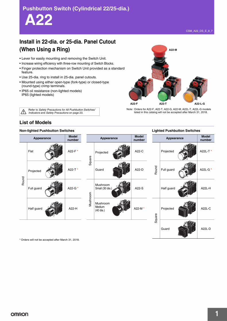
Pushbutton Switch (Cylindrical 22/25-dia.)
A22Install in 22-dia. or 25-dia. Panel Cutout (When Using a Ring)• Lever for easily mounting and removing the Switch Unit.• Increase wiring efficiency with three-row mounting of Switch Blocks.• Finger protection mechanism on Switch Unit provided as a standard
feature.• Use 25-dia. ring to install in 25-dia. panel cutouts.• Mounted using either open-type (fork-type) or closed-type
(round-type) crimp terminals.• IP65 oil resistance (non-lighted models)
IP65 (lighted models)
Refer to Safety Precautions for All Pushbutton Switches/Indicators and Safety Precautions on page 23.
Note: Orders for A22-F, A22-T, A22-G, A22-M, A22L-T, A22L-G models listed in this catalog will not be accepted after March 31, 2018.
A22-M
A22-TA22-F A22-L-G
List of ModelsNon-lighted Pushbutton Switches Lighted Pushbutton Switches
* Orders will not be accepted after March 31, 2018.
Appearance Model number Appearance Model
number Appearance Model number
Rou
nd
Flat A22-F *
Squ
are
Projected A22-CR
ound
Projected A22L-T *
Projected A22-T * Guard A22-D Full guard A22L-G *
Full guard A22-G *
Mus
hroo
m
Mushroom Small (30 dia.) A22-S Half guard A22L-H
Half guard A22-H
Mushroom Medium (40 dia.) A22-M *
Squ
are
Projected A22L-C
Guard A22L-D
A22
2
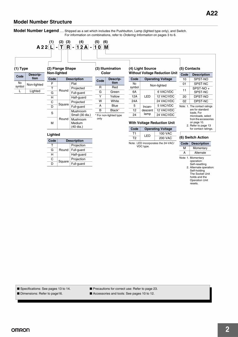
Model Number Structure
Model Number Legend ..... Shipped as a set which includes the Pushbutton, Lamp (lighted type only), and Switch.For information on combinations, refer to Ordering Information on pages 3 to 6.
(1) (2) (3) (4) (5) (6)
A 2 2 L - T R - 1 2 A - 1 0 M
(2) Flange ShapeNon-lighted
Lighted
Code DescriptionF
Round
FlatT ProjectedG Full-guardH Half-guardC
SquareProjected
D Full-guard
S
Round
Mushroom Small (30 dia.)
MMushroom Medium (40 dia.)
Code DescriptionT
RoundProjection
G Full-guardH Half-guardC
SquareProjection
D Full-guard
(1) Type
Code Descrip-tion
No symbol Non-lighted
L Lighted
(3) Illumination Color
* For non-lighted type only
Code Descrip-tion
R RedG GreenY YellowW WhiteA BlueB Black*
(4) Light SourceWithout Voltage Reduction Unit
With Voltage Reduction Unit
Note: LED incorporates the 24-VAC/ VDC type.
Code Operating VoltageNo
symbol Non-lighted
6ALED
6 VAC/VDC12A 12 VAC/VDC24A 24 VAC/VDC
5 Incan-descent
lamp
5 VAC/VDC12 12 VAC/VDC24 24 VAC/VDC
Code Operating VoltageT1
LED100 VAC
T2 200 VAC
(5) Contacts
Note: 1. The contact ratings are for standard loads. For microloads, select from the accessories on page 10.
2. Refer to page 13 for contact ratings.
Code Description10 SPST-NO01 SPST-NC
11 SPST-NO + SPST-NC
20 DPST-NO02 DPST-NC
(6) Switch Action
Note: 1. Momentary operation: Self-resetting
2. Alternate operation: Self-holdingThe Socket Unit holds and the Operation Unit resets.
Code DescriptionM MomentaryA Alternate
■ Specifications: See pages 13 to 14. ■ Precautions for correct use: Refer to page 23.
■ Dimensions: Refer to page16. ■ Accessories and tools: See pages 10 to 12.

A22
3
Ordering Information
Completely Assembled........ Shipped as a set which includes the Pushbutton, Lamp (lighted type only), and Switch.Non-lighted (Round Type)
Note: The contact ratings are for standard loads.* Orders will not be accepted after March 31, 2018.
Non-lighted (Square Type)
Note: The contact ratings are for standard loads.
Operation Momentary opera-tion (self-resetting)
Alternate operation (self-holding) Illumination color
Appearance Output Set SetRound/Flat typeA22-F
SPST-NO A22-F@-10M * A22-F@-10A *
R (red)Y (yellow)G (green)W (white)A (blue)B (black)
SPST-NC A22-F@-01M * A22-F@-01A *SPST-NO + SPST-NC A22-F@-11M * A22-F@-11A *DPST-NO A22-F@-20M * A22-F@-20A *DPST-NC A22-F@-02M * A22-F@-02A *
Round/Projection typeA22-T
SPST-NO A22-T@-10M * A22-T@-10A *SPST-NC A22-T@-01M * A22-T@-01A *SPST-NO + SPST-NC A22-T@-11M * A22-T@-11A *SPST-NO + SPST-NO A22-T@-20M * A22-T@-20A *SPST-NC + SPST-NC A22-T@-02M * A22-T@-02A *
Round/Full-guard typeA22-G
SPST-NO A22-G@-10M * A22-G@-10A *SPST-NC A22-G@-01M * A22-G@-01A *SPST-NO + SPST-NC A22-G@-11M * A22-G@-11A *SPST-NO + SPST-NO A22-G@-20M * A22-G@-20A *SPST-NC + SPST-NC A22-G@-02M * A22-G@-02A *
Round/Half-guard typeA22-H
SPST-NO A22-H@-10M A22-H@-10ASPST-NC A22-H@-01M A22-H@-01ASPST-NO + SPST-NC A22-H@-11M A22-H@-11ASPST-NO + SPST-NO A22-H@-20M A22-H@-20ASPST-NC + SPST-NC A22-H@-02M A22-H@-02A
Round/Small-sizeMushroom type(30-dia. head)A22-S
SPST-NO A22-S@-10M
---
SPST-NC A22-S@-01MSPST-NO + SPST-NC A22-S@-11MSPST-NO + SPST-NO A22-S@-20MSPST-NC + SPST-NC A22-S@-02M
Round/Medium-sizeMushroom type(40-dia head)A22-M
SPST-NO A22-M@-10M *SPST-NC A22-M@-01M *SPST-NO + SPST-NC A22-M@-11M *SPST-NO + SPST-NO A22-M@-20M *SPST-NC + SPST-NC A22-M@-02M *
Operation Momentary opera-tion (self-resetting)
Alternate operation (self-holding) Illumination color
Appearance Output Set SetSquare/Projection typeA22-C
SPST-NO A22-C@-10M A22-C@-10A
R (red)Y (yellow)G (green)W (white)A (blue)B (black)
SPST-NC A22-C@-01M A22-C@-01ASPST-NO + SPST-NC A22-C@-11M A22-C@-11ASPST-NO + SPST-NO A22-C@-20M A22-C@-20ASPST-NC + SPST-NC A22-C@-02M A22-C@-02A
Square/Guard typeA22-D
SPST-NO A22-D@-10M A22-D@-10ASPST-NC A22-D@-01M A22-D@-01ASPST-NO + SPST-NC A22-D@-11M A22-D@-11ASPST-NO + SPST-NO A22-D@-20M A22-D@-20ASPST-NC + SPST-NC A22-D@-02M A22-D@-02A
Individual models: Refer to pages 7 to 9.(The Pushbutton, Lamp, and Switch can be ordered
■ Specifications: See pages 13 to 14. ■ Dimensions: Refer to page 16.■ Accessories and tools: See pages 10 to 12.
A22
4
Ordering Information
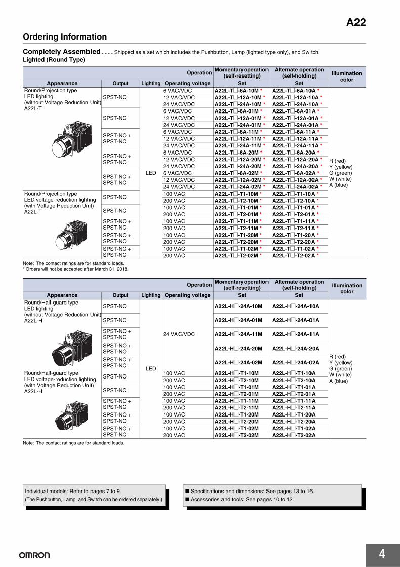
Completely Assembled ........Shipped as a set which includes the Pushbutton, Lamp (lighted type only), and Switch.Lighted (Round Type)
Note: The contact ratings are for standard loads.* Orders will not be accepted after March 31, 2018.
Note: The contact ratings are for standard loads.
Operation Momentary operation (self-resetting)
Alternate operation (self-holding) Illumination
colorAppearance Output Lighting Operating voltage Set Set
Round/Projection type LED lighting (without Voltage Reduction Unit)A22L-T
SPST-NO
LED
6 VAC/VDC A22L-T@-6A-10M * A22L-T@-6A-10A *
R (red)Y (yellow)G (green)W (white)A (blue)
12 VAC/VDC A22L-T@-12A-10M * A22L-T@-12A-10A *24 VAC/VDC A22L-T@-24A-10M * A22L-T@-24A-10A *
SPST-NC6 VAC/VDC A22L-T@-6A-01M * A22L-T@-6A-01A *12 VAC/VDC A22L-T@-12A-01M * A22L-T@-12A-01A *24 VAC/VDC A22L-T@-24A-01M * A22L-T@-24A-01A *
SPST-NO + SPST-NC
6 VAC/VDC A22L-T@-6A-11M * A22L-T@-6A-11A *12 VAC/VDC A22L-T@-12A-11M * A22L-T@-12A-11A *24 VAC/VDC A22L-T@-24A-11M * A22L-T@-24A-11A *
SPST-NO + SPST-NO
6 VAC/VDC A22L-T@-6A-20M * A22L-T@-6A-20A *12 VAC/VDC A22L-T@-12A-20M * A22L-T@-12A-20A *24 VAC/VDC A22L-T@-24A-20M * A22L-T@-24A-20A *
SPST-NC + SPST-NC
6 VAC/VDC A22L-T@-6A-02M * A22L-T@-6A-02A *12 VAC/VDC A22L-T@-12A-02M * A22L-T@-12A-02A *24 VAC/VDC A22L-T@-24A-02M * A22L-T@-24A-02A *
Round/Projection type LED voltage-reduction lighting (with Voltage Reduction Unit)A22L-T
SPST-NO 100 VAC A22L-T@-T1-10M * A22L-T@-T1-10A *200 VAC A22L-T@-T2-10M * A22L-T@-T2-10A *
SPST-NC 100 VAC A22L-T@-T1-01M * A22L-T@-T1-01A *200 VAC A22L-T@-T2-01M * A22L-T@-T2-01A *
SPST-NO + SPST-NC
100 VAC A22L-T@-T1-11M * A22L-T@-T1-11A *200 VAC A22L-T@-T2-11M * A22L-T@-T2-11A *
SPST-NO + SPST-NO
100 VAC A22L-T@-T1-20M * A22L-T@-T1-20A *200 VAC A22L-T@-T2-20M * A22L-T@-T2-20A *
SPST-NC + SPST-NC
100 VAC A22L-T@-T1-02M * A22L-T@-T1-02A *200 VAC A22L-T@-T2-02M * A22L-T@-T2-02A *
Operation Momentary operation (self-resetting)
Alternate operation (self-holding) Illumination
colorAppearance Output Lighting Operating voltage Set Set
Round/Half-guard typeLED lighting (without Voltage Reduction Unit)A22L-H
SPST-NO
LED
24 VAC/VDC
A22L-H@-24A-10M A22L-H@-24A-10A
R (red)Y (yellow)G (green)W (white)A (blue)
SPST-NC A22L-H@-24A-01M A22L-H@-24A-01A
SPST-NO + SPST-NC A22L-H@-24A-11M A22L-H@-24A-11A
SPST-NO + SPST-NO A22L-H@-24A-20M A22L-H@-24A-20A
SPST-NC + SPST-NC A22L-H@-24A-02M A22L-H@-24A-02A
Round/Half-guard typeLED voltage-reduction lighting (with Voltage Reduction Unit)A22L-H
SPST-NO 100 VAC A22L-H@-T1-10M A22L-H@-T1-10A200 VAC A22L-H@-T2-10M A22L-H@-T2-10A
SPST-NC 100 VAC A22L-H@-T1-01M A22L-H@-T1-01A200 VAC A22L-H@-T2-01M A22L-H@-T2-01A
SPST-NO + SPST-NC
100 VAC A22L-H@-T1-11M A22L-H@-T1-11A200 VAC A22L-H@-T2-11M A22L-H@-T2-11A
SPST-NO + SPST-NO
100 VAC A22L-H@-T1-20M A22L-H@-T1-20A200 VAC A22L-H@-T2-20M A22L-H@-T2-20A
SPST-NC + SPST-NC
100 VAC A22L-H@-T1-02M A22L-H@-T1-02A200 VAC A22L-H@-T2-02M A22L-H@-T2-02A
Individual models: Refer to pages 7 to 9.(The Pushbutton, Lamp, and Switch can be ordered separately.)
■ Specifications and dimensions: See pages 13 to 16.■ Accessories and tools: See pages 10 to 12.

A22
5
Ordering Information
Completely Assembled........ Shipped as a set which includes the Pushbutton, Lamp (lighted type only), and Switch.Lighted (Round Type)
Note: The contact ratings are for standard loads.* Orders will not be accepted after March 31, 2018.
Operation Momentary operation (self-resetting)
Alternate operation (self-holding) Illumination
colorAppearance Output Lighting Operating voltage Set Set
Round/Full-guard type LED lighting (without Voltage Reduction Unit)A22L-G
SPST-NO
LED
6 VAC/VDC A22L-G@-6A-10M * A22L-G@-6A-10A *
R (red)Y (yellow)G (green)W (white)A (blue)
12 VAC/VDC A22L-G@-12A-10M * A22L-G@-12A-10A *24 VAC/VDC A22L-G@-24A-10M * A22L-G@-24A-10A *
SPST-NC6 VAC/VDC A22L-G@-6A-01M * A22L-G@-6A-01A *12 VAC/VDC A22L-G@-12A-01M * A22L-G@-12A-01A *24 VAC/VDC A22L-G@-24A-01M * A22L-G@-24A-01A *
SPST-NO + SPST-NC
6 VAC/VDC A22L-G@-6A-11M * A22L-G@-6A-11A *12 VAC/VDC A22L-G@-12A-11M * A22L-G@-12A-11A *24 VAC/VDC A22L-G@-24A-11M * A22L-G@-24A-11A *
SPST-NO + SPST-NO
6 VAC/VDC A22L-G@-6A-20M * A22L-G@-6A-20A *12 VAC/VDC A22L-G@-12A-20M * A22L-G@-12A-20A *24 VAC/VDC A22L-G@-24A-20M * A22L-G@-24A-20A *
SPST-NC + SPST-NC
6 VAC/VDC A22L-G@-6A-02M * A22L-G@-6A-02A *12 VAC/VDC A22L-G@-12A-02M * A22L-G@-12A-02A *24 VAC/VDC A22L-G@-24A-02M * A22L-G@-24A-02A *
Round/Full-guard typeLED voltage-reduction lighting (with Voltage Reduction Unit)A22L-G
SPST-NO100 VAC A22L-G@-T1-10M * A22L-G@-T1-10A *200 VAC A22L-G@-T2-10M * A22L-G@-T2-10A *
SPST-NC100 VAC A22L-G@-T1-01M * A22L-G@-T1-01A *200 VAC A22L-G@-T2-01M * A22L-G@-T2-01A *
SPST-NO + SPST-NC
100 VAC A22L-G@-T1-11M * A22L-G@-T1-11A *200 VAC A22L-G@-T2-11M * A22L-G@-T2-11A *
SPST-NO + SPST-NO
100 VAC A22L-G@-T1-20M * A22L-G@-T1-20A *200 VAC A22L-G@-T2-20M * A22L-G@-T2-20A *
SPST-NC + SPST-NC
100 VAC A22L-G@-T1-02M * A22L-G@-T1-02A *200 VAC A22L-G@-T2-02M * A22L-G@-T2-02A *
Individual models: Refer to pages 7 to 9. (The Pushbutton, Lamp, and Switch can be ordered separately.)
■ Specifications and dimensions: Refer to pages 13 to 16.■ Accessories and tools: See pages 10 to 12.
A22
6
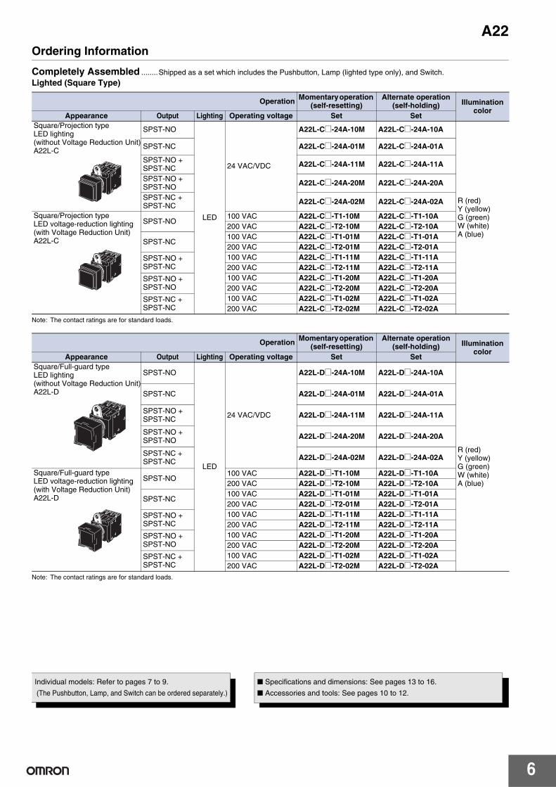
Ordering Information
Completely Assembled ........Shipped as a set which includes the Pushbutton, Lamp (lighted type only), and Switch.Lighted (Square Type)
Note: The contact ratings are for standard loads.
Note: The contact ratings are for standard loads.
Operation Momentary operation (self-resetting)
Alternate operation (self-holding) Illumination
colorAppearance Output Lighting Operating voltage Set Set
Square/Projection typeLED lighting (without Voltage Reduction Unit)A22L-C
SPST-NO
LED
24 VAC/VDC
A22L-C@-24A-10M A22L-C@-24A-10A
R (red)Y (yellow)G (green)W (white)A (blue)
SPST-NC A22L-C@-24A-01M A22L-C@-24A-01A
SPST-NO + SPST-NC A22L-C@-24A-11M A22L-C@-24A-11A
SPST-NO + SPST-NO A22L-C@-24A-20M A22L-C@-24A-20A
SPST-NC + SPST-NC A22L-C@-24A-02M A22L-C@-24A-02A
Square/Projection typeLED voltage-reduction lighting (with Voltage Reduction Unit)A22L-C
SPST-NO100 VAC A22L-C@-T1-10M A22L-C@-T1-10A200 VAC A22L-C@-T2-10M A22L-C@-T2-10A
SPST-NC100 VAC A22L-C@-T1-01M A22L-C@-T1-01A200 VAC A22L-C@-T2-01M A22L-C@-T2-01A
SPST-NO + SPST-NC
100 VAC A22L-C@-T1-11M A22L-C@-T1-11A200 VAC A22L-C@-T2-11M A22L-C@-T2-11A
SPST-NO + SPST-NO
100 VAC A22L-C@-T1-20M A22L-C@-T1-20A200 VAC A22L-C@-T2-20M A22L-C@-T2-20A
SPST-NC + SPST-NC
100 VAC A22L-C@-T1-02M A22L-C@-T1-02A200 VAC A22L-C@-T2-02M A22L-C@-T2-02A
Operation Momentary operation (self-resetting)
Alternate operation (self-holding) Illumination
colorAppearance Output Lighting Operating voltage Set Set
Square/Full-guard typeLED lighting (without Voltage Reduction Unit)A22L-D
SPST-NO
LED
24 VAC/VDC
A22L-D@-24A-10M A22L-D@-24A-10A
R (red)Y (yellow)G (green)W (white)A (blue)
SPST-NC A22L-D@-24A-01M A22L-D@-24A-01A
SPST-NO + SPST-NC A22L-D@-24A-11M A22L-D@-24A-11A
SPST-NO + SPST-NO A22L-D@-24A-20M A22L-D@-24A-20A
SPST-NC + SPST-NC A22L-D@-24A-02M A22L-D@-24A-02A
Square/Full-guard typeLED voltage-reduction lighting (with Voltage Reduction Unit)A22L-D
SPST-NO100 VAC A22L-D@-T1-10M A22L-D@-T1-10A200 VAC A22L-D@-T2-10M A22L-D@-T2-10A
SPST-NC100 VAC A22L-D@-T1-01M A22L-D@-T1-01A200 VAC A22L-D@-T2-01M A22L-D@-T2-01A
SPST-NO + SPST-NC
100 VAC A22L-D@-T1-11M A22L-D@-T1-11A200 VAC A22L-D@-T2-11M A22L-D@-T2-11A
SPST-NO + SPST-NO
100 VAC A22L-D@-T1-20M A22L-D@-T1-20A200 VAC A22L-D@-T2-20M A22L-D@-T2-20A
SPST-NC + SPST-NC
100 VAC A22L-D@-T1-02M A22L-D@-T1-02A200 VAC A22L-D@-T2-02M A22L-D@-T2-02A
Individual models: Refer to pages 7 to 9.
(The Pushbutton, Lamp, and Switch can be ordered separately.)
■ Specifications and dimensions: See pages 13 to 16.
■ Accessories and tools: See pages 10 to 12.
A22
7
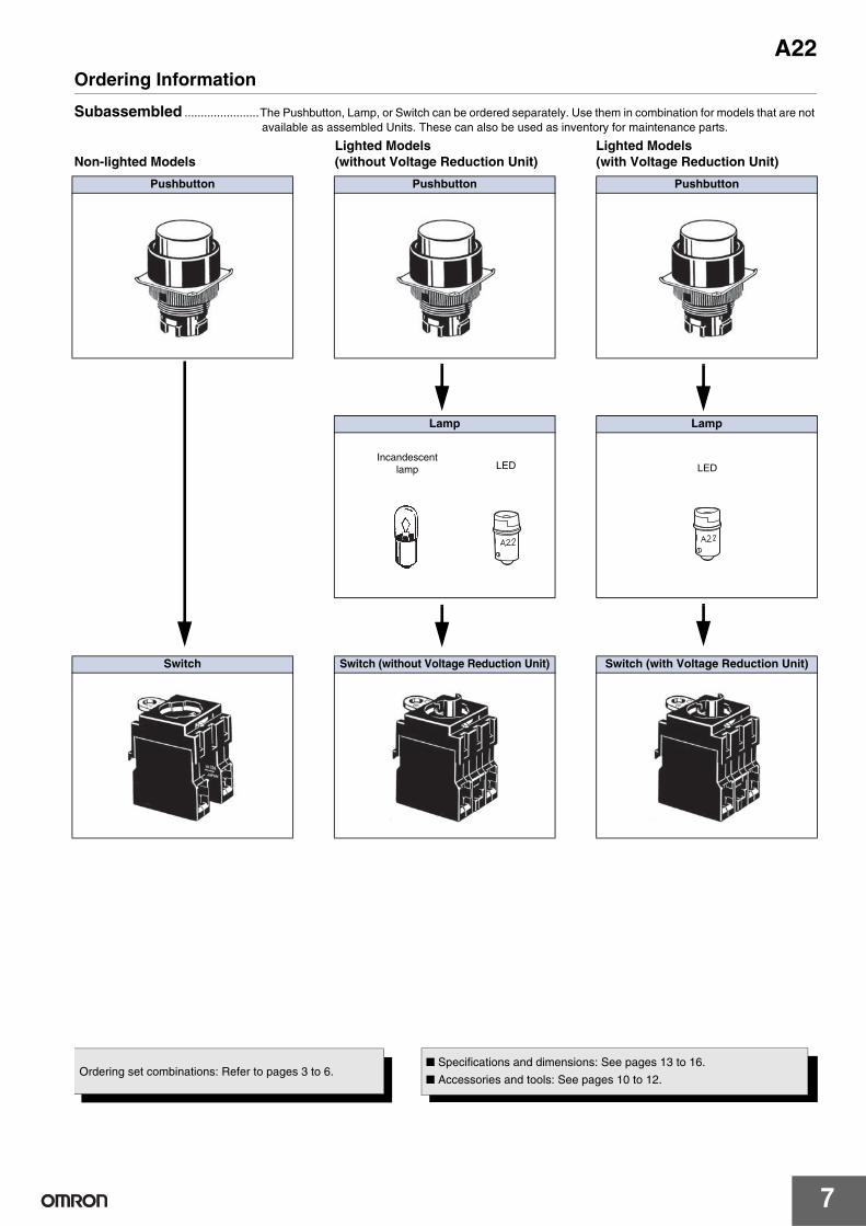
Ordering Information
Subassembled .......................The Pushbutton, Lamp, or Switch can be ordered separately. Use them in combination for models that are not available as assembled Units. These can also be used as inventory for maintenance parts.
Lighted Models Lighted Models Non-lighted Models (without Voltage Reduction Unit) (with Voltage Reduction Unit)
Pushbutton Pushbutton Pushbutton
Lamp Lamp
Switch Switch (without Voltage Reduction Unit) Switch (with Voltage Reduction Unit)
Incandescentlamp LED LED
Ordering set combinations: Refer to pages 3 to 6.■ Specifications and dimensions: See pages 13 to 16.
■ Accessories and tools: See pages 10 to 12.
A22
8
Ordering Information
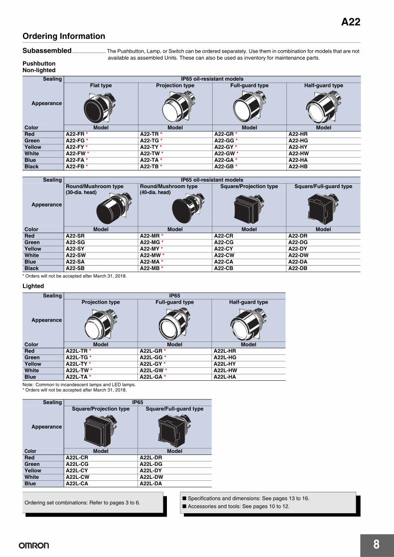
Subassembled ....................... The Pushbutton, Lamp, or Switch can be ordered separately. Use them in combination for models that are not available as assembled Units. These can also be used as inventory for maintenance parts.
PushbuttonNon-lighted
* Orders will not be accepted after March 31, 2018.
Lighted
Note: Common to incandescent lamps and LED lamps.* Orders will not be accepted after March 31, 2018.
Sealing IP65 oil-resistant models
Appearance
Flat type Projection type Full-guard type Half-guard type
Color Model Model Model ModelRed A22-FR * A22-TR * A22-GR * A22-HRGreen A22-FG * A22-TG * A22-GG * A22-HGYellow A22-FY * A22-TY * A22-GY * A22-HYWhite A22-FW * A22-TW * A22-GW * A22-HWBlue A22-FA * A22-TA * A22-GA * A22-HABlack A22-FB * A22-TB * A22-GB * A22-HB
Sealing IP65 oil-resistant models
Appearance
Round/Mushroom type(30-dia. head)
Round/Mushroom type (40-dia. head)
Square/Projection type Square/Full-guard type
Color Model Model Model ModelRed A22-SR A22-MR * A22-CR A22-DRGreen A22-SG A22-MG * A22-CG A22-DGYellow A22-SY A22-MY * A22-CY A22-DYWhite A22-SW A22-MW * A22-CW A22-DWBlue A22-SA A22-MA * A22-CA A22-DABlack A22-SB A22-MB * A22-CB A22-DB
Sealing IP65
Appearance
Projection type Full-guard type Half-guard type
Color Model Model ModelRed A22L-TR * A22L-GR * A22L-HRGreen A22L-TG * A22L-GG * A22L-HGYellow A22L-TY * A22L-GY * A22L-HYWhite A22L-TW * A22L-GW * A22L-HWBlue A22L-TA * A22L-GA * A22L-HA
Sealing IP65
Appearance
Square/Projection type Square/Full-guard type
Color Model ModelRed A22L-CR A22L-DRGreen A22L-CG A22L-DGYellow A22L-CY A22L-DYWhite A22L-CW A22L-DWBlue A22L-CA A22L-DA
Ordering set combinations: Refer to pages 3 to 6.■ Specifications and dimensions: See pages 13 to 16.■ Accessories and tools: See pages 10 to 12.

A22
9
Ordering Information
Subassembled .......................The Pushbutton, Lamp, or Switch can be ordered separately. Use them in combination for models that are not available as assembled Units. These can also be used as inventory for maintenance parts.
LampLED Lamp
*1. For voltage-reduction lighting, use the A22-24A@. Only 24-V LED lamps can be used.*2. Used when the Pushbutton color is yellow or white.
Incandescent Lamp
Switch (Standard Load)No Voltage Reduction Unit
Voltage Reduction Unit
*1. A DPST-NO model is shown here as an example.*2. For a model with a Voltage Reduction Unit, use the A22-24A@. Only 24-V LED lamps can be used.
Operating voltage 6 VAC/VDC 12 VAC/VDC 24 VAC/VDCAppearance LED Color Model Model Model
AC and DC
Red A22-6AR A22-12AR A22-24ARGreen A22-6AG A22-12AG A22-24AGYellow *2 A22-6AY A22-12AY A22-24AYBlue A22-6AA A22-12AA A22-24AA
Appearance Operatingvoltage 5 VAC/VDC 12 VAC/VDC 24 VAC/VDC
A22-5 A22-12 A22-24
Classification
Appearance
Non-lighted Lighted
Operation Momentary Alternate Momentary AlternateContacts Model Model Model Model
Standard load
SPST-NO A22-10M A22-10A A22L-10M A22L-10ASPST-NC A22-01M A22-01A A22L-01M A22L-01ASPST-NO + SPST-NC A22-11M A22-11A A22L-11M A22L-11ASPST-NO + SPST-NO A22-20M A22-20A A22L-20M A22L-20ASPST-NC + SPST-NC A22-02M A22-02A A22L-02M A22L-02A
Classification
Appearance
110 VAC, Lighted 220 VAC, Lighted
Operation Momentary Alternate Momentary AlternateContacts Model Model Model Model
Standard load
SPST-NO A22L-10M-T1 A22L-10A-T1 A22L-10M-T2 A22L-10A-T2SPST-NC A22L-01M-T1 A22L-01A-T1 A22L-01M-T2 A22L-01A-T2SPST-NO + SPST-NC A22L-11M-T1 A22L-11A-T1 A22L-11M-T2 A22L-11A-T2SPST-NO + SPST-NO A22L-20M-T1 A22L-20A-T1 A22L-20M-T2 A22L-20A-T2SPST-NC + SPST-NC A22L-02M-T1 A22L-02A-T1 A22L-02M-T2 A22L-02A-T2
Ordering set combinations: Refer to pages 3 to 6.■ Specifications and dimensions: See pages 13 to 16.
■ Accessories and tools: See pages 10 to 12.

A22
10
Ordering Information
Accessories (Order Separately)Accessories
Item Appearance Classification Model Remarks
Switch Blocks
SPST-NO Standard load A22-10
Order Switch Blocks to add an SPST-NO (A22-10) or SPST-NC (A22-01) Switch Block (for standard loads) or to replace a Switch Block.An A22Z-3003 Three-throw Spacer is re-quired to mount three Non-lighted Switch Units.
Microload A22-10S
SPST-NC Standard load A22-01Microload A22-01S
DPST-NO Standard load A22-20Microload A22-20S
DPST-NC Standard load A22-02Microload A22-02S
SPST-NO + SPST-NC Standard load A22-11Microload A22-11S
Lamp Sockets
Direct lighting A22-TN
Voltage-reduction lighting
110 VAC A22-T1 Used when changing the lighting method. (LED only)220 VAC A22-T2
Mounting LatchesFor momentary models A22-3200 Provided as standard. Order Mounting
Latches only when mounting Switch Blocks or Lamp Sockets that are purchased individ-ually.For alternate models A22-3210
Legend Plate Frames
Standard size
With Snap-in Legend Plate (Without text)
White A22Z-3321
Snap-in Legend Plate is acrylic.Red A22Z-3322Black A22Z-3323
Without Snap-in Legend Plate A22Z-3320
Large sizeWith Snap-in Legend Plate (Without text)
White A22Z-3331
Snap-in Legend Plate is acrylic.Red A22Z-3332Black A22Z-3333
Without Snap-in Legend Plate A22Z-3330
Lock Ring Round A22Z-3360 This Lock Ring is used when a more secure lock feature is required.
Metallic Bezel RingsFor flat or projection models A22Z-3580 Replace with the standard model.
Material: Copper alloy-Nickel chrome platingCannot be used with the M22.For full-guard models A22Z-3582
Sealing Caps
For flat models A22Z-3600F Used to prevent dust or water from entering the Operation Unit (Pushbutton, etc.).Color: opaqueMaterial: silicon
For projection models A22Z-3600T
For full-guard models A22Z-3600G
Color Caps
Red A22Z-30TRUsed for changing the Pushbutton color of the (round) Pushbutton Switches. Cannot be used, however, with Half-guard Switch-es.
Green A22Z-30TGYellow A22Z-30TYWhite A22Z-30TWBlue A22Z-30TA
CapsFor A22 For projection, full-guard, or half-guard models A22Z-3490
Material: polycarbonate resinFor M22 For round models A22Z-3495
Three-throw Spacer --- A22Z-3003
Used when mounting three Nonlighted Switches. Cannot be used with Alternate action type, knob-type Selector, and Key-type Selector because of the structure. Mushroom-type Switch provides an A22Z-3003, three-throw spacer. (See page 28.)
Hole Plug Round A22Z-3530Can be plugged into pre-cut panel holes for future expansion. The color is black.Color: Black
Control Boxes(Enclosures)
One holeA22Z-B101
For those designed A22Z-B1@, DPST-NO or DPST-NC Switches cannot be used.A22Z-B2@ Control Boxes, A22-series alter-nate operation models, and DPST-NO, DPST-NC, and SPST-NO + SPST-NC con-tacts cannot be used.Material: Polycarbonate resin
A22Z-B201
One hole, yellow boxA22Z-B101YA22Z-B201Y
Two holesA22Z-B102A22Z-B202
Three holesA22Z-B103A22Z-B203
Connectors Applicable cable diameter (mm)
7 to 9 dia. A22Z-3500-1 Plastic connector used to extend a cable from the Switch Box. (See 9 to 11 dia. A22Z-3500-2 page 27.)9 to 11 dia. A22Z-3500-2
A22
11
Ordering Information
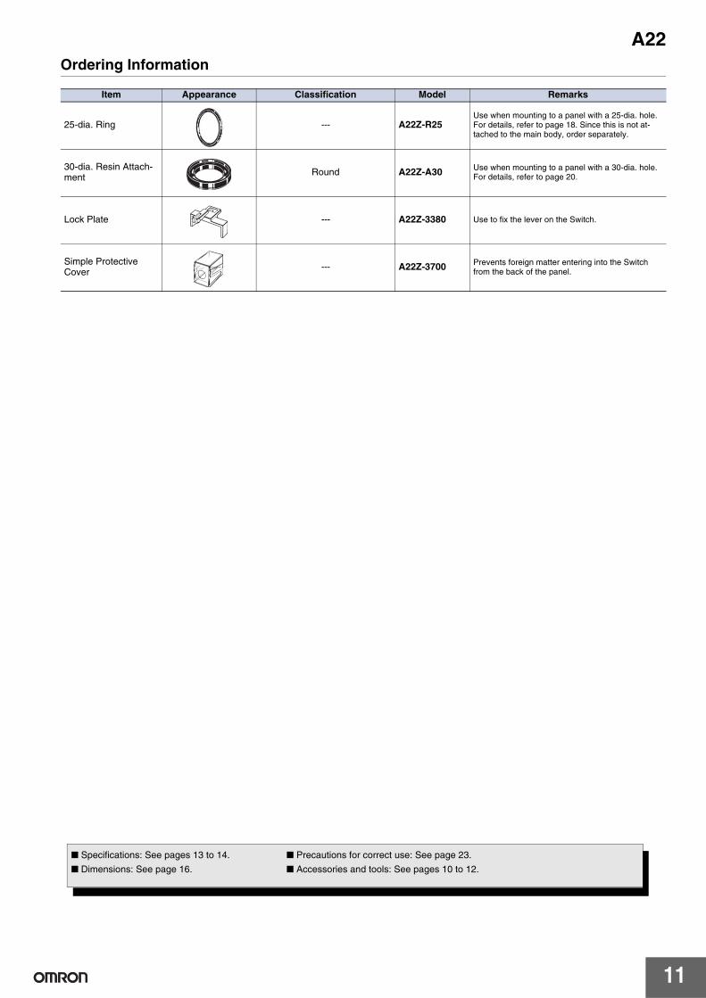
Item Appearance Classification Model Remarks
25-dia. Ring --- A22Z-R25Use when mounting to a panel with a 25-dia. hole. For details, refer to page 18. Since this is not at-tached to the main body, order separately.
30-dia. Resin Attach-ment Round A22Z-A30 Use when mounting to a panel with a 30-dia. hole.
For details, refer to page 20.
Lock Plate --- A22Z-3380 Use to fix the lever on the Switch.
Simple Protective Cover --- A22Z-3700 Prevents foreign matter entering into the Switch
from the back of the panel.
■ Specifications: See pages 13 to 14. ■ Precautions for correct use: See page 23.
■ Dimensions: See page 16. ■ Accessories and tools: See pages 10 to 12.

A22
12
Ordering Information
Tools
Item Appearance Classification Model Remarks
Snap-in Legend Plates
Standard size
Without text
Black A22Z-3443B
Attached to the Stan-dard-size Legend Plate Frame. (See page 28.)Material: Acrylic
Red A22Z-3443RWhite A22Z-3443W
Transparent A22Z-3443C
With text
White text on red background
❍ A22Z-3443R-2STOP A22Z-3443R-4
White text on black background
| A22Z-3443B-1START A22Z-3443B-3
ON A22Z-3443B-5OFF A22Z-3443B-6UP A22Z-3443B-7
DOWN A22Z-3443B-8POWER ON A22Z-3443B-9
OFF-ON A22Z-3443B-10
Large size Without text
Black A22Z-3453B Used as an Emergency Stop Switch Legend Plate. (See page 28.)Material: Acrylic
Red A22Z-3453RWhite A22Z-3453W
Transparent A22Z-3453C
For Emer-gency Stop Switch
Black text on yellow back-ground
60-dia. round plate with black letters on a yellow background A22Z-3466-1 EMERGENCY STOP is
engraved on the plate. Used as an Emergency Stop Switch Legend Plate
90-dia. round plate with black letters on a yellow background A22Z-3476-1
Character Films
No print (Round) A22Z-3460After printing on a film, af-fix to the indicator plate of the Lighted Pushbutton Switch. (The back is coated with adhesive.)
Character print(Round)
| A22Z-3460-1❍ A22Z-3460-2
START A22Z-3460-3STOP A22Z-3460-4
No print (Square) A22Z-3480
Item Appearance Classification Model Remarks
Lamp Extractor --- A22Z-3901 Rubber tool used to easily replace Lamps
Tightening Wrench --- A22Z-3905Used to tighten mounting nuts from the back of the panel and to replace the cap of the Lighted Emergency Switch.
Cap Tightening Tool --- A22Z-3908 Used for replacing the cap of the Half-guard Pushbutton Switch.
Cap Puller --- A3PJ-5080Used for removing the cap from the Pushbutton of the Square Lighted Push-button Switch.
■ Specifications: See pages 13 to 14. ■ Precautions for correct use: See page 23.
■ Dimensions: See page 16. ■ Accessories and tools: See pages 10 to 12.
A22
13
Specifications
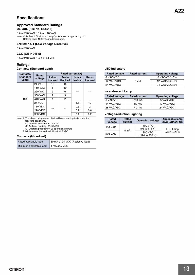
Approved Standard RatingsUL, cUL (File No. E41515)6 A at 220 VAC, 10 A at 110 VACNote: Only Switch Blocks and Lamp Sockets are recognized by UL.
Refer to Page 10 for the model numbers.
EN60947-5-1 (Low Voltage Directive)3 A at 220 VAC
CCC (GB14048.5)3 A at 240 VAC, 1.5 A at 24 VDC
RatingsContacts (Standard Load)
Note: 1. The above ratings were obtained by conducting tests under the following conditions.(1) Ambient temperature: 20±2°C(2) Ambient humidity: 65±5% RH(3) Operating frequency: 20 operations/minute
2. Minimum applicable load: 10 mA at 5 VDC
Contacts (Microload)
LED Indicators
Incandescent Lamp
Voltage-reduction Lighting
Contacts (Standard
Load)
Rated voltage
Rated current (A)Induc-
tive loadResis-
tive loadInduc-
tive loadResis-
tive load
10A
24 VAC 10 10
--- ---110 VAC 5 10220 VAC 3 6380 VAC 2 3440 VAC 1 224 VDC
--- ---
1.5 10110 VDC 0.5 2220 VDC 0.2 0.6380 VDC 0.1 0.2
Rated applicable load 50 mA at 24 VDC (Resistive load)
Minimum applicable load 1 mA at 5 VDC
Rated voltage Rated current Operating voltage6 VAC/VDC
8 mA6 VAC/VDC±5%
12 VAC/VDC 12 VAC/VDC±5%24 VAC/VDC 24 VAC/VDC±5%
Rated voltage Rated current Operating voltage6 VAC/VDC 200 mA 5 VAC/VDC14 VAC/VDC 80 mA 12 VAC/VDC28 VAC/VDC 40 mA 24 VAC/VDC
Rated voltage
Rated current Operating voltage Applicable lamp
(BA9S/Base: 13)
110 VAC8 mA
100 VAC (95 to 115 V) LED Lamp
(A22-24A@)220 VAC 200 VAC
(190 to 230 V)

A22
14
Specifications
Characteristics
*1. Malfunction within 1 ms.*2. With no icing or condensation.*3. Degree of protection from the front of the panel.
Operating Characteristics (for SPST-NO/SPST-NC)
* Rotation torque for Knob-type Selector and Key-type Selector Switches.
Type Pushbutton Switches Knob-type Selector Switches Key-typeSelector Switch Indicator
Item
Non-lighted models:A22-F A22-TA22-G A22-HA22-S A22-MA22-C A22-D
Lighted models:A22L-T A22L-GA22L-H A22L-CA22L-D
Non-lighted model:A22S
Lighted model: A22W
Non-lighted model: A22K M22
Allowable operating frequency
Mechanical Momentary operation:60 operations/minute max.
Manual reset: 30 operations/minute max.Automatic reset: 30 operations/minute max.
---
Electrical 30 operations/minute max. ---
Insulation resistance 100 MΩ min. (at 500 VDC)
Contact resistance
Standard load 100 mΩ max. (initial value)
Microload 100 mΩ max. (initial value)
Dielectric strength
Between termi-nals of same polarity
2,500VAC, 50/60Hz for 1min
Between each terminal and ground
2,500VAC, 50/60Hz for 1min
Vibration resistance Malfunction *1 Malfunction *2: 10 to 55 Hz, 1.5-mm double amplitude
Shock resistance
Destruction 1,000 m/s2 max. 1,000 m/s2 max. 1,000 m/s2 max. 1,000 m/s2 max. 1,000 m/s2 max. 1,000 m/s2 max.
Malfunction *1 1,000 m/s2 max. 600 m/s2 max. 1,000 m/s2 max. 600 m/s2 max. 1000 m/s2 max. 600 m/s2 max.
DurabilityMechanical Momentary operation:
5,000,000 operations min.500,000
operations min.100,000
operations min.500,000
operations min. ---
Electrical 500,000 operations min. 500,000 operations min.
100,000 operations min.
500,000 operations min. ---
Ambient operating temperature * 2 −20°C to 70°C −20°C to 55°C −20°C to 70°C −20°C to 55°C −20°C to 70°C −20°C to 55°C
Ambient operating humidity 35% to 85% RH
Ambient storage temperature *2 −40°C to 70°C
Degree of protection *3 IP65 (oil-resistant) IP65 IP65
(oil-resistant) IP65 IP65 (oil-resistant) IP65
Electric shock protection class Class II
PTI (tracking characteristic) 175
Degree of contamination 3 (IEC947-5-1)
Type Pushbutton Switches Knob-type Selector Key-type Selector Switch
Item
Lighted Nonlighted Pushbutton
SwitchesManual reset Automatic reset Manual reset Automatic reset
A22-F A22-TA22-G A22-HA22-C A22-DA22-S A22-MA22L-T A22L-GA22L-H A22L-CA22L-D
A22SA22W A22K
Total travel force (TTF) max. 29.4 N 0.34 N·m* 0.25 N·m for two notches *
0.34 N·m for three notches * 0.34 N·m* 0.25 N·m for two notches *0.34 N·m for three notches *
Total travel (TT) 5.5 mm max. Approx. 90° for two notches(Approx. 45° for three notches)
Approx. 90° for two notches(Approx. 45° for three notches)
Resetting force (RF) min. --- 0.34 N·m max.* --- 0.34 N·m max.* ---

A22
15
Nomenclature
Model Structure
Push b utton
Lo c k Ring
Lamp
• Light Source LED lamp Incandescent lamp
Switch
• Contacts
• Lighting Method
Non-lighted: Red, Green, Yellow, White, Blue, Black Lighted: Red, Green Yellow, White, Blue
SPST-NO, SPST-NC, SPST-NO + SPST-NC, SPST-NO + SPST-NO, SPST-NC + SPST-NC (Minimum applicable load: 10 mA at 5 VDC)
Non-lighted Lighted (without Voltage Reduction Unit) Lighted (with Voltage Reduction Unit)
The above illustration shows a lighted model.
• Available Colors

A22
16
Dimensions (Unit: mm)
Lighted/Non-lighted Pushbutton Switches (The following illustrations are for momentary operation.)
Note: Lighted models have the same dimensions as shown above, whether they are with or without Voltage Reduction Units.* Alternate operation models are 9.3 mm longer.
1.8
5.9
0.5
27R
3436
12
30
28
29.7 dia.
54.7 *
0.51.8
5.9
29.7 dia.
12 64
34
1.85.9
0.5
44
12
29.7 dia.
72.7 *
Flat Type/A22-F For SPST-NO (SPST-NC) Switches For SPST-NO (SPDT-NC) Alternate Operation Switches
For DPST-NO (DPST-NC) Monoblock-contact Switches
29.7 dia.
5.9
1.8
0.5
18.5
34
12 54.7 *
Half-guard Type/A22-H/A22L-H
1.8
5.90.5
34
19 54.7 *
29.7 dia. 23.9 dia.
Projection Type/A22-T/A22L-T
1.8
5.90.5
34
19
29.7 dia.
54.7 *
Full-guard Type/A22-G/A22L-G
1.8
5.90.5
34
32
40 dia.
54.7 *
40-dia. Mushroom Type/A22-M
1.8
5.9
0.5
34
54.7 *18
12
25.6 × 25.6
29.8 × 29.8
Square/Projection type/A22-C/A22L-C
1.8
5.90.5
34
18
5.3
54.7 *
829.8 × 29.8
Square/Full-guard Type/A22-D/A22L-D

A22
17
Dimensions (Unit: mm)
Terminal Arrangement (Bottom View)
Terminal Connection
Panel Cutouts
Lock ring is provided as a standard item.• When applying coating such as paint to the panel, the dimensions should be those after the application of coating.• Recommended panel thickness: 1 to 5 mm.• Use an A22Z-R25 Ring when mounting to a panel with 25-mm holes.
Non-lighted(SPST-NO + SPST-NC)
Lighted(SPST-NO + SPST-NC)
Non-lighted(DPST-NO + DPST-NC)
Item Terminal connection
Non-lighted (SPST-NO + SPST-NC)
Non-lighted (DPST-NO + DPST-NC)
Lighted without Voltage Reduction Unit (SPST-NO + SPST-NC)
Lighted with Voltage Reduction Unit (SPST-NO + SPST-NC)
16.7
20.7
Switch BlocksM3.5 screw
22
10Switch Blocks
Lamp socket
12
20.7
Switch Blocks
32
3
4
1
2
BOTTOM VIEW
11
21
22
12
13
23
24
14
BOTTOM VIEW
1
2 X2
X1
X
(−)
(+)
3
4
BOTTOM VIEW
3
4
X1
X2
1
2
X
BOTTOM VIEW
22.3+0.40 25+0.5
0dia. dia.

A22
18
Dimensions (Unit: mm)
Accessories
0.30.1
27
8.3
40.830.3
15
20.5
2.829.8
28 dia.28 dia.
0.31.5
0.3
2.2
22.2± dia.
Legend Plate FramesStandard Models A22Z-332@ 27
18
50.8
30.3
15
20.5
2.829.8
28 dia.28 dia.
0.31.5
0.3
2.2
0.30.122.2± dia.
Large A22Z-333@
10.6
dia
.
9.5
dia.
20 ±1.5
BA9S/13Model indication
LampLED A22-6@, 12@, 24@
28 max.
10±
1 di
a.
BA9S/13
Incandescent lamp A22-5, 12, 24
22.2 dia.
2.8
20.530 dia.
21
Lock Ring A22Z-3360
0.51.3
22 d
ia.
24.8
dia
.27
dia
.
25-dia. Ring A22Z-R25
23.4 dia.10.2
Color Cap A22Z-30T@
30 dia.
132.5
1
6Hole Plug (Round) A22Z-3530
1
17.6
19.6
dia
.
5.2
17.9
dia
.
Caps
A22 (for round models) A22Z-3490
17.6
22.5
1 11.1
24.1
dia
.21
.4 d
ia.
21.1
dia
.
23.7
dia
.
M22 (for round models) A22Z-3495

A22
19
Dimensions (Unit: mm)
32 dia.
16.6
22.2 dia.33 dia.
1R 31.5 dia.
24
22.2 dia.32.5 dia.
1R32 dia.
(26 dia.)
22.2 dia.33 dia.
R1
R2
14.5
23
Sealing CapsFor Flat Models A22Z-3600F For projection models A22Z-3600T For full-guard models A22Z-3600G
28.7 dia.
24± 0.20
29.7± 0.3 dia.
M27 P
=1
5
11.5
dia.
5
18.5
28.7 dia.
24± 0.20
29.7± 0.3 dia.
M27 P
=1
dia.
Metallic Bezel RingsFor Flat/Projection Models A22Z-3580 For full-guard models
A22Z-3582
26.88.2
1
26.8
17.9
1
Snap-in Legend PlatesFor Standard Models A22Z-3443@-@ For Large Models A22Z-3453@
E
EE
M
R N CY
S T O P
G
t1
Black letters
Yellow
22.2 dia.
90 dia.
E
E E
M
R NCY
S T O P
G
60 dia.
22.2 dia.t1
Yellow
Black letters
For Emergency-stop Models A22Z-3476-1 (90 dia.) A22Z-3466-1 (60 dia.)
17±0.2
t 0.22
17±
0.2
1.2± 0.20
1.2±
0.2
0
0.10.
2
19.4±
Character FilmFor Round Models A22Z-3460-@
21.5 × 21.5± 0.20.3
t 0.22
For Square Models A22Z-3480

A22
20
Dimensions (Unit: mm)
8.5 dia.11 dia.
12.5
17.5
55
8 dia.
Lamp Extractor A22Z-3901
30 dia.
4.5 2090 2
19.2
dia
.21
.2 d
ia.
25 d
ia.
Tightening Wrench A22Z-3905
5 dia.
20.523.4
1
30
Cap Tightening Tool A22Z-3908
6.13.8
20.5
2.8
22.2 dia.
34.7 dia.
30-dia. Resin Attachment A22Z-A30
2.5 2.5
5 10
20
15
50
25±2
0.3
Cap Puller A3PJ-5080
34.530.1
5.37.3 dia.
13.2 4
5
1016.5
4
9.7
188
Lock Plate A22Z-3380
2.8
78.816.5
22.5 dia.
56
20.5
47.2
47
50
0.3 recess
42.229.5
9
57.5
25.1
30 × 30
Simple Protective Cover A22Z-3700
10.8
6
2.5
13.7 dia.
12.9 dia.
9
116.1
3.414.2 dia.
Three-throw Spacer A22Z-3003

A22
21
Dimensions (Unit: mm)
Control Box (Enclosure) A22Z-B10@
20.5
2.8
22.1 dia.
(10x36) 0.6-mm concave surface (Lead cable hole)
Two, 21 dia.10
75
6836
20
41
69.5
Case (black)
Cover (*)
Four, M4 Phillips binding screws
(Lead cable hole)Two mounting holes
16±1 dia.
41
32
39
56
A22Z-B101 (One Hole)A22Z-B101Y
Cable Port Hole (Top View)
* A22Z-B101: grayA22Z-B101Y: yellow
16±1 dia
(10x36) 0.6-mm concave surface (Lead cable hole)
(Lead cable hole)
Two mounting holes 21 dia.
Two, 22.1 dia.
41
94
101
56
20
41
69.5
36
68
10
137
50
Case (black)
Cover (gray)
Four, M4 Phillips binding screws
A22Z-B102 (Two Holes) Cable Port Hole (Top View)
36
68
10
199
5050
20 41
69.5
56
163
156
41
16±1 dia (10x36) 0.6-mm concave surface
(Lead cable hole)
(Lead cable hole)
Two mounting holes 21 dia.
Three, 22.1 dia.
Case (black)
Cover (gray)
Four, M4 Phillips binding screws
A22Z-B103 (Three Holes) Cable Port Hole (Top View)
6.3
4.3
3R
(Panel Mounting Hole)

A22
22
Dimensions (Unit: mm)
Control Box A22Z-B20@
22.1 dia.
Four, M4 Phillips binding screws
(10×36) 0.6-mmconcave surface
Two, 21 dia.
Case (black)
Cover (*)
Two, 19 dia.(base)
21 dia.(both sides)
Two mountingholes
1630
.5
60
10
68
20.5
2.8
6836
40
54
A22Z-B201 (One Hole)A22Z-B201Y
Cable Port Hole (Top View)
* A22Z-B201: grayA22Z-B201Y: yellow
Two, 22.1 dia. Four, M4 Phillips binding screws
(10×36) 0.6-mm concave surface
Two, 21 dia.
Case (black)
Cover (gray)
Two, 19 dia. (base)
21 dia. (both sides)
Two mounting holes
40
78
98
54
16 30
.5
60
36
68
10 13750
A22Z-B202 (Two Holes) Cable Port Hole (Top View)
Four, M4 Phillips binding screws
(10×36) 0.6-mmconcave surface
Two, 21 dia.
Case (black)
Cover (gray)
Two, 19 dia.(base)
21 dia.(both sides)
Two mountingholes
Three, 22.1 dia.
1630
.5
60
36 68
10
199
5050
40 54
158
138
A22Z-B203 (Three Holes) Cable Port Hole (Top View)
6.3
4.3
3R
(Panel Mounting Hole)

A22
23
Safety Precautions
Refer to Safety Precautions for All Pushbutton Switches/Indicators.
Do not apply a voltage between the incandescent lamp and the terminal that is greater than the rated voltage. If the incandescent lamp is broken, the Operation Units may pop out.Always turn OFF the power and wait for 10 minutes before replacing the incandescent lamp. If the lamp is replaced immediately after the power is turned OFF, the remaining heat may cause burns.
Mounting• Do not perform wiring with power supplied to the Switch. Do not
touch the terminals or other charged parts of the Switch while power is being supplied. Doing so may result in electric shock.
• Always make sure that the power is turned OFF before mounting, removing, or wiring the Switch, or performing maintenance.Do not tighten the mounting ring more than necessary using tools such as pointed-nose pliers. Doing so will damage the mounting ring.The tightening torque is 0.98 to 1.96 N·m.
• Recommended panel thickness: 1 to 5 mm.• When mounting the caps after changing the LED or the caps,
tighten the caps at a tightening torque of 0.49 tp 0.78 N·m.Wiring• Terminal screws must be Phillips or slotted M3.5 screws with a
square washer.• The tightening torque is 1.08 to 1.27 N·m.• Solid wires, stranded wires, and crimp terminals can be connected
to the Switch.Applicable Wire SizeStranded wire: 2 mm2 max.Solid wire: 1.6 dia. max.
Bare Crimp Terminals
Crimp Terminals with Insulating Sheath
• After wiring the Switch, maintain an appropriate clearance and creepage distance.
Operating Environment• The IP65 model is designed with a degree of protection so that it
will not sustain damage if it is subjected to water from any direction to the front of the panel.
• This switch is intended for indoor use only.Using the Switch outdoors will result in failure.
LED• The LED current-limiting resistor is built-in, so internal resistance is
not required.• If commercially available LEDs are used, select the ones that meet
the following conditions:Base: BA9S/13Overall length: 26 mm max.Power consumption: 2.6 W max.When DC-specific LEDs are used, wire the Switch so that the X1 terminal is positive.
• Mis-lighting of the LEDThe LED lights with approx. 0.1 mA or less of micro-current. Take a countermeasure like adding a resistor to prevent mis-lighting in parallel to the LED.The micro-current varies with the machine (leak current or stray capacity between cables, etc.). Select resistance value and allowable power consumption that meet the actual current.
Others• If the panel is to be finished with coating, etc., make sure that the
panel meets the specified dimensions after the coating.• Do not subject the Switch to extreme shock or vibration. Doing so
will cause malfunctions and damage to the Switch.
Using the Microload• Insert a contact protection circuit, if necessary, to prevent the
reduction of life expectancy due to extreme wear on the contacts caused by loads where inrush current occurs when the contact is opened and closed.The minimum applicable load is the N-level reference value. This value indicates the malfunction reference level for the reliability level of 60% (λ 60) (conforming to JIS C5003).The equation, λ 60 = 0.5 x 10⁻⁶/operations indicates that the estimated malfunction rate is less than 1/2,000,000 operations with a reliability level of 60%.
WARNING
Precautions for Correct Use
8 mm max. 8 mm max.
16.0 mm max. 16.0 mm max.
8 mm max.
20.2 mm max.
8 mm max.
20.2 mm max.
X1
X2
LEDlamp
R:10kΩ (1W)Bleeder resistor
(Circuit example)In case of using 24 VAC/VDC, Direct lighting
Microload area Standardload area
Invalidarea
0.1 1 10 100 1,000
10 mA1 mA5
12
24
300.16 mA 1.6 mA 100 mA
Current (mA)
0
Vol
tage
(V
)

A22
24
ApplicationMounting to the PanelPanel Hole Dimensions• Panel hole dimensions are given below.• Recommended panel thickness: 1 to 5 mm.
• For 25-dia. holes, always use 25-dia. Rings. (Since the cutout dimensions are large, IP65 cannot be guaranteed unless 25-dia. Rings are used.)
• If outer surface treatment such as coating is performed for the panel, the panel dimensions after outer surface treatment must meet the specified panel dimensions.
Matrix Installation
1. The following panel hole dimensions apply when Switch Unit and the Standard-size Legend Plate Frame and Lock Ring are mounted, and lead wires are connected directly to the Switch Block.
2. The following panel hole dimensions apply when the Large-size Legend Plate Frame is mounted, and when crimp terminals are connected to the Switch Block terminals.
For 1. above:
For 2. above:
Note: 1. The above dimensions are the minimum dimensions for when the wires described under Applicable Wire Size on page 23 are used. If a different wires are used, the wiring dimensions may be different so determine an appropriate pitch before setup.
2. With pushbuttons of external dimensions greater than 30 mm, set the pitch according to the dimensions. (When using matrix installation for the A22-M@, mount with a pitch of 40 mm instead of 30 mm in the diagram above.)
Mounting the Operation Unit on the Panel• Insert the Operation Unit (Pushbutton, etc.) from the front surface of the
panel, insert the Lock Ring and the mounting nut from the terminal side, then tighten the nut. Before tightening, check that the rubber washer is present between the Pushbutton Unit and the panel.
• When using a Legend Plate Frame, put one rubber washer each between the Legend Plate Frame and the panel and between the Operation Unit and the Legend Plate Frame. (One rubber washer will be provided when one Legend Plate Frame is ordered.)
• Align the Lock Ring with the groove in the casing, then insert the Lock Ring so that its edge is located on the panel side.
22.3+0.40
+0.20
+0.
4 0
22.3
25 dia.22 dia.
+0.40 25+0.5
0
3.2
24.1
0.8R max.
Not Using a Lock Ring Using a Lock Ring
Switch Blocks A
A22-10, A22-10SA22-01, A22-01S 45 mm min.
A22-20, A22-20S, A22-02A22-02S, A22-11, A22-11S 55 mm min.
Type of crimp terminal Switch Blocks B
Bare crimp terminals
A22-10, A22-10SA22-01, A22-01S 51 mm min.
A22-20, A22-20S, A22-02A22-02S, A22-11, A22-11S 61 mm min.
Crimp terminals with insulating sheath
A22-10, A22-10SA22-01, A22-01S 60 mm min.
A22-20, A22-20S, A22-02A22-02S, A22-11, A22-11S 70 mm min.
30
A
30
B
Pitches A and B between the centers of the mounting holes are as follows:
A22
25
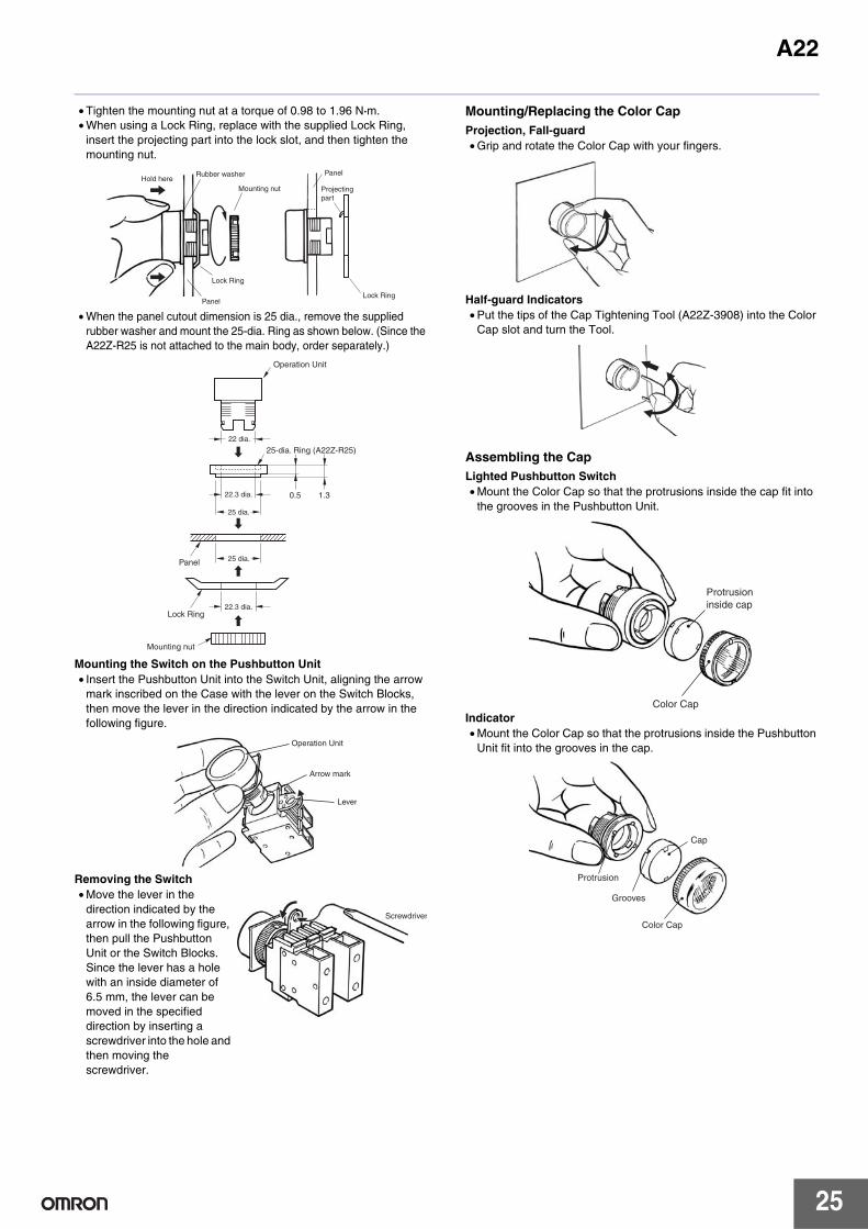
• Tighten the mounting nut at a torque of 0.98 to 1.96 N·m.• When using a Lock Ring, replace with the supplied Lock Ring,
insert the projecting part into the lock slot, and then tighten the mounting nut.
• When the panel cutout dimension is 25 dia., remove the supplied rubber washer and mount the 25-dia. Ring as shown below. (Since the A22Z-R25 is not attached to the main body, order separately.)
Mounting the Switch on the Pushbutton Unit• Insert the Pushbutton Unit into the Switch Unit, aligning the arrow
mark inscribed on the Case with the lever on the Switch Blocks, then move the lever in the direction indicated by the arrow in the following figure.
Removing the Switch• Move the lever in the
direction indicated by the arrow in the following figure, then pull the Pushbutton Unit or the Switch Blocks.Since the lever has a hole with an inside diameter of 6.5 mm, the lever can be moved in the specified direction by inserting a screwdriver into the hole and then moving the screwdriver.
Mounting/Replacing the Color CapProjection, Fall-guard• Grip and rotate the Color Cap with your fingers.
Half-guard Indicators• Put the tips of the Cap Tightening Tool (A22Z-3908) into the Color
Cap slot and turn the Tool.
Assembling the CapLighted Pushbutton Switch• Mount the Color Cap so that the protrusions inside the cap fit into
the grooves in the Pushbutton Unit.
Indicator• Mount the Color Cap so that the protrusions inside the Pushbutton
Unit fit into the grooves in the cap.
Hold hereRubber washer
Mounting nut
Panel
Projectingpart
Lock RingPanel
Lock Ring
22.3 dia.
0.5 1.3
Lock Ring
Mounting nut
Panel 25 dia.
25 dia.
22.3 dia.
25-dia. Ring (A22Z-R25)22 dia.
Operation Unit
Operation Unit
Arrow mark
Lever
Screwdriver
Protrusion inside cap
Color Cap
Protrusion
Grooves
Cap
Color Cap
A22
26
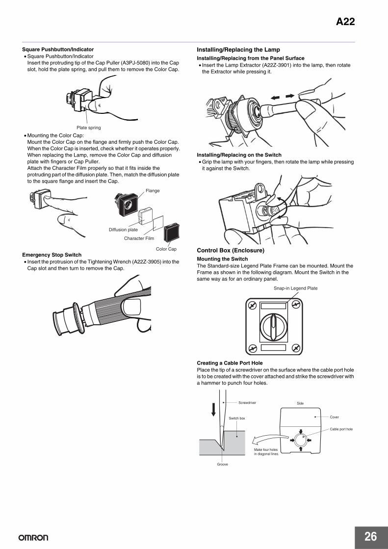
Square Pushbutton/Indicator• Square Pushbutton/Indicator
Insert the protruding tip of the Cap Puller (A3PJ-5080) into the Cap slot, hold the plate spring, and pull them to remove the Color Cap.
• Mounting the Color Cap:Mount the Color Cap on the flange and firmly push the Color Cap.When the Color Cap is inserted, check whether it operates properly.When replacing the Lamp, remove the Color Cap and diffusion plate with fingers or Cap Puller.Attach the Character Film properly so that it fits inside the protruding part of the diffusion plate. Then, match the diffusion plate to the square flange and insert the Cap.
Emergency Stop Switch• Insert the protrusion of the Tightening Wrench (A22Z-3905) into the
Cap slot and then turn to remove the Cap.
Installing/Replacing the LampInstalling/Replacing from the Panel Surface• Insert the Lamp Extractor (A22Z-3901) into the lamp, then rotate
the Extractor while pressing it.
Installing/Replacing on the Switch• Grip the lamp with your fingers, then rotate the lamp while pressing
it against the Switch.
Control Box (Enclosure)Mounting the SwitchThe Standard-size Legend Plate Frame can be mounted. Mount the Frame as shown in the following diagram. Mount the Switch in the same way as for an ordinary panel.
Creating a Cable Port HolePlace the tip of a screwdriver on the surface where the cable port hole is to be created with the cover attached and strike the screwdriver with a hammer to punch four holes.
Plate spring
Flange
Diffusion plate
Character Film
Color Cap
Snap-in Legend Plate
Switch box
Screwdriver
Groove
Side
Make four holes in diagonal lines.
Cover
Cable port hole

A22
27
Securing the Connector Cable1. Insert the connector into the cable port hole in the Box and secure
with the fixing nut inside the box.2. Open a hole in the thin rubber section of the rubber ring.3. Pass the tightening cap through the cable, insert the cable into the
connector, and tighten the hexagonal nut to secure the cable.
Switch BlocksInstalling the Switch Blocks• Hook the small protrusion on the Switch Block into the groove on
the Mounting Latch on the other side of the lever, then push up the Switch Block in the direction indicated by the arrow in the figure below.
Removing the Switch Blocks• Insert a screwdriver between the Mounting Latch and the Switch
Block, then push down the screwdriver in the direction indicated by the arrow in the following figure.
WiringWiring Round Crimp Terminals• Loosen the terminal screw from the Switch Unit until it completely
comes off the groove, insert a screwdriver as shown in the following figure, then push up the washer in the direction indicated by the arrow to temporarily secure it. Now, a round crimp terminal can be connected. After inserting the terminal, tighten the screws to complete wiring.
Engraving
• Engrave the characters on the surface on the Cap. Make sure that the characters are aligned parallel to the imaginary line connecting the two protruding portions to the left and right of the Cap.
• The characters must not be engraved deeper than 0.5 mm. Apply an alcohol-based paint coating, such as melamine, alkyd, or acrylic resin paint coating, to the engraved characters.
Cable diameter Connector7 to 9 dia. A22Z-3500-19 to 11 dia. A22Z-3500-2
Fixing nut Rubber washer
Connector
Tightening cap
Cable
Inside Outside
Box
MountingLatch
Lever
Protrusion
Switch Block
Use either of the following screwdrivers.
Flat-headscrewdriver
Phillipsscrewdriver
3 to 6 mm
3 to 6 mm
Screwdriver
Screwdriver
Washer
Screw
Protruding portions on Cap

A22
28
Affixing Character Film• Hold the Cap, remove the cardboard on the Film, and attach the
Film to the Cap. Make sure that the protruding portions of the Cap engage he cutout portions of the Film and that the characters are aligned parallel to the imaginary line connecting the two protruding portions to the left and right of the Cap.
Mounting and Dismounting Snap-in Legend• Press and secure the Snap-in Legend Plate onto the Legend Plate
Frame.• The direction of the characters will vary with the mounting direction
of the control panel if the Switch is a knob or key selector model.
• To easily remove the Snap-in Legend Plate from the Legend Plate Frame mounted to the panel, insert a Tool with a thin tip into the space between the Snap-in Legend Plate and the Legend Plate Frame.
• The Snap-in Legend Plate is easily removed by pressing the Snap-in Legend Plate from the back of the Legend Plate Frame.
• The Legend Plate Frame is made of acrylic resin, which is easily damaged by shock. Be sure to handle the Legend Plate Frame with care.
Engraving MethodMaterial: Acrylic• Engrave the characters directly on the matted side of the Snap-in
Legend Plate.• The characters must be engraved no deeper than 0.5 mm.• Apply alcohol-based paint coating to the engraved characters.• If the Snap-in Legend Plate is transparent, engrave the mirror-
written characters on the back of the Snap-in Legend Plate and apply paint coating to the characters. Then apply paint coating of a different color to the remaining part of the Snap-in Legend Plate.
Mounting Three-throw SpacerPress and secure the two protruding portions of the Three-throw Spacer to the two indented portions of the inner side of the control panel.
Protruding portions on Cap
Remove the cardboard.
Legend Plate Frame
Snap-in Legend Plate
Concave surface

A22
29
Mounting the 30-dia. Resin Attachment
Pushbutton
Rubber washer (Operation Unit mounting part)
Rubber washer (included)
Mounting panel
Lock Ring
Mounting nut
Attachment

Terms and Conditions Agreement Read and understand this catalog. Please read and understand this catalog before purchasing the products. Please consult your OMRON representative if you have any questions or comments. Warranties. (a) Exclusive Warranty. Omron’s exclusive warranty is that the Products will be free from defects in materials and workmanship for a period of twelve months from the date of sale by Omron (or such other period expressed in writing by Omron). Omron disclaims all other warranties, express or implied. (b) Limitations. OMRON MAKES NO WARRANTY OR REPRESENTATION, EXPRESS OR IMPLIED, ABOUT NON-INFRINGEMENT, MERCHANTABILITY OR FITNESS FOR A PARTICULAR PURPOSE OF THE PRODUCTS. BUYER ACKNOWLEDGES THAT IT ALONE HAS DETERMINED THAT THE PRODUCTS WILL SUITABLY MEET THE REQUIREMENTS OF THEIR INTENDED USE. Omron further disclaims all warranties and responsibility of any type for claims or expenses based on infringement by the Products or otherwise of any intellectual property right. (c) Buyer Remedy. Omron’s sole obligation hereunder shall be, at Omron’s election, to (i) replace (in the form originally shipped with Buyer responsible for labor charges for removal or replacement thereof) the non-complying Product, (ii) repair the non-complying Product, or (iii) repay or credit Buyer an amount equal to the purchase price of the non-complying Product; provided that in no event shall Omron be responsible for warranty, repair, indemnity or any other claims or expenses regarding the Products unless Omron’s analysis confirms that the Products were properly handled, stored, installed and maintained and not subject to contamination, abuse, misuse or inappropriate modification. Return of any Products by Buyer must be approved in writing by Omron before shipment. Omron Companies shall not be liable for the suitability or unsuitability or the results from the use of Products in combination with any electrical or electronic components, circuits, system assemblies or any other materials or substances or environments. Any advice, recommendations or information given orally or in writing, are not to be construed as an amendment or addition to the above warranty. See http://www.omron.com/global/ or contact your Omron representative for published information. Limitation on Liability; Etc. OMRON COMPANIES SHALL NOT BE LIABLE FOR SPECIAL, INDIRECT, INCIDENTAL, OR CONSEQUENTIAL DAMAGES, LOSS OF PROFITS OR PRODUCTION OR COMMERCIAL LOSS IN ANY WAY CONNECTED WITH THE PRODUCTS, WHETHER SUCH CLAIM IS BASED IN CONTRACT, WARRANTY, NEGLIGENCE OR STRICT LIABILITY. Further, in no event shall liability of Omron Companies exceed the individual price of the Product on which liability is asserted. Suitability of Use. Omron Companies shall not be responsible for conformity with any standards, codes or regulations which apply to the combination of the Product in the Buyer’s application or use of the Product. At Buyer’s request, Omron will provide applicable third party certification documents identifying ratings and limitations of use which apply to the Product. This information by itself is not sufficient for a complete determination of the suitability of the Product in combination with the end product, machine, system, or other application or use. Buyer shall be solely responsible for determining appropriateness of the particular Product with respect to Buyer’s application, product or system. Buyer shall take application responsibility in all cases. NEVER USE THE PRODUCT FOR AN APPLICATION INVOLVING SERIOUS RISK TO LIFE OR PROPERTY OR IN LARGE QUANTITIES WITHOUT ENSURING THAT THE SYSTEM AS A WHOLE HAS BEEN DESIGNED TO ADDRESS THE RISKS, AND THAT THE OMRON PRODUCT(S) IS PROPERLY RATED AND INSTALLED FOR THE INTENDED USE WITHIN THE OVERALL EQUIPMENT OR SYSTEM. Programmable Products. Omron Companies shall not be responsible for the user’s programming of a programmable Product, or any consequence thereof. Performance Data. Data presented in Omron Company websites, catalogs and other materials is provided as a guide for the user in determining suitability and does not constitute a warranty. It may represent the result of Omron’s test conditions, and the user must correlate it to actual application requirements. Actual performance is subject to the Omron’s Warranty and Limitations of Liability. Change in Specifications. Product specifications and accessories may be changed at any time based on improvements and other reasons. It is our practice to change part numbers when published ratings or features are changed, or when significant construction changes are made. However, some specifications of the Product may be changed without any notice. When in doubt, special part numbers may be assigned to fix or establish key specifications for your application. Please consult with your Omron’s representative at any time to confirm actual specifications of purchased Product. Errors and Omissions. Information presented by Omron Companies has been checked and is believed to be accurate; however, no responsibility is assumed for clerical, typographical or proofreading errors or omissions.
2018.4
In the interest of product improvement, specifications are subject to change without notice.
OMRON Corporation Industrial Automation Company http://www.ia.omron.com/
(c)Copyright OMRON Corporation 2018 All Right Reserved.