Embed Size (px)
DESCRIPTION
pv design with compress
Citation preview

11/8/2013
1
Introduction
COMPRESS is an interactive program which is used for design new pressure vessel or estimate safety in future for existing vessel.
COMPRESS task is to design or rate pressure vessel & heat exchangers as much as possible using industry standard methods.

11/8/2013
2
pressure vessel
Codes used ………ASME Code

11/8/2013
3
Wind Codes NBC Wind Code
UBC Wind Code
ASCE Wind Code
IBC 2000 Wind Code
User Defined Wind Code
The wind force coefficient for asmooth cylinder is 0.60, while thecoefficient for a vessel is normallytaken as 0.80.
Wind Force Coefficient (Cf)
Basic Wind SpeedEach geographic location has abasic wind speed as shownon the basic wind speed map.
Exposure A,B,C,D
Exposure ALarge city centers with a least 50% of the buildings havinga height in excess of 70 feet.
Exposure BUrban and suburban areas, wooded areas, or other terrainwith numerous closely spaced obstructions.
Exposure C
Open terrain with scattered obstructions having heightgenerally less than 30 feet.
Exposure DFlat, unobstructed areas exposed to wind flowing over large bodies of water.

11/8/2013
4
Seismic Code
ASCE 7-02, 7-98 Seismic Code
ASCE 7-95, 7-93 Seismic Code
ASCE 7-88 Seismic Code
NBC 1995 - 1990 Seismic Code
UBC 1991 - 1997 Seismic Code
User Defined Seismic Co de
Soil Profile (S1, S2, S3, S4)
S1 is a profile with either rock of any characteristic, either shale-like or crystalline in nature, that has a shear wave velocity greater than 2,500 feet per second
S2A soil profile with deep cohesion less or stiff clay conditions where the soil depth exceeds 200 feet and the soil types overlying rock are stable deposits of sands, gravels, or stiff clays
S3 A soil profile containing 20 to 40 feet in thickness of soft to medium-stiff clays with or without intervening layers of cohesion less soils.
S4 A soil profile characterized by a shear wave velocity of less than 500 feet per second containing more than 40 feet of soft clays or silts.

11/8/2013
5
Importance Factor (I)COMPRESS will take defaults value of 1.
Foundation Factor (F)COMPRESS will take defaults value of F=1.5
Force Modification Factor (R)suggested value of R = 3
Coefficient RwRecommend values for Rw (Rw Factors for Nonbuilding Structures) is 3 for vessels on legs or 4 if the vessel is skirt supported
Material Menu

11/8/2013
6
To avoid search through a long list of seldom used materials COMPRESS uses the concept of a user specified "short list". Only materials that have been selected from the full databaselisting are displayed in the short list
Stresses (Material Allowable Stresses)COMPRESS automatically supplies allowable stress values when you enter the material specification and design temperature for a component
Temperature
Specifying the temperature for internal pressure, COMPRESSlooks up the appropriate allowable stress automatically
Gasket Details

11/8/2013
7
Structural Sections
Structural sections are used for construction of supports, lugs, platforms.
Tips on Designing a VesselStart with the top or left head (this is really important) Design from the top down for towers, left to right for horizontal vessels

11/8/2013
8
HEAD
HEADCOMPRESS
can design following types of head for vertical as well as horizontal vessel.EllipsoidalTorispherical Hemispherical Dished coverBolted coverWelded cover

11/8/2013
9
F & D HeadCrown Inner Radius
Crown inner radius is generally taken as inside dia of vessel (0.8 to 1.2 ID of vessel)
Knuckle Inner Radius
knuckle radius = 6 to 10% of the inside crownradius

11/8/2013
10
Straight flange length
Straight flange length is generally taken as 50 mm
Ellipsoidal Head Head Ratio (D/2h)
In ASME standard ellipsoidal head ratio is 2
Bolted CoverFactor C
For flanges having full face gaskets, the value isC = 0.25

11/8/2013
11
Cylinder
Cylinder MDMTThe minimum design metal temperature is the lowest operating temperature. In some cases it is minimum ambient temperature
Test
The MAP (maximum allowable pressure -new and cold) is calculated at the testtemperature entered

11/8/2013
12
Material NormalizedIf a UCS material is normalized, the temperature at which impact testing is required is lower thanwhen the material is not normalized
PWHT Performed
PWHT (post weld heat treatment) is guided by ASME code when the process is done at lowtemperature
PWHT to be performed for carbon steel and lowalloy steel welded vessels if the vessel is to containa lethal substance
Maximize MDMT/No MAWPIf this is checked, then COMPRESS will find the lowest MDMT possible for the component
If the material chosen is a pipe material or if it is aseamless head, it will prompt that no radiography will required
Longitudinal Seam X-Ray
Copy LastThe Copy Last pushbutton automatically duplicates all information from the last similar component (to the left)If a similar component has not yet been added to the vessel, COMPRESS will copy all informationfrom the last component added
11/8/2013
13
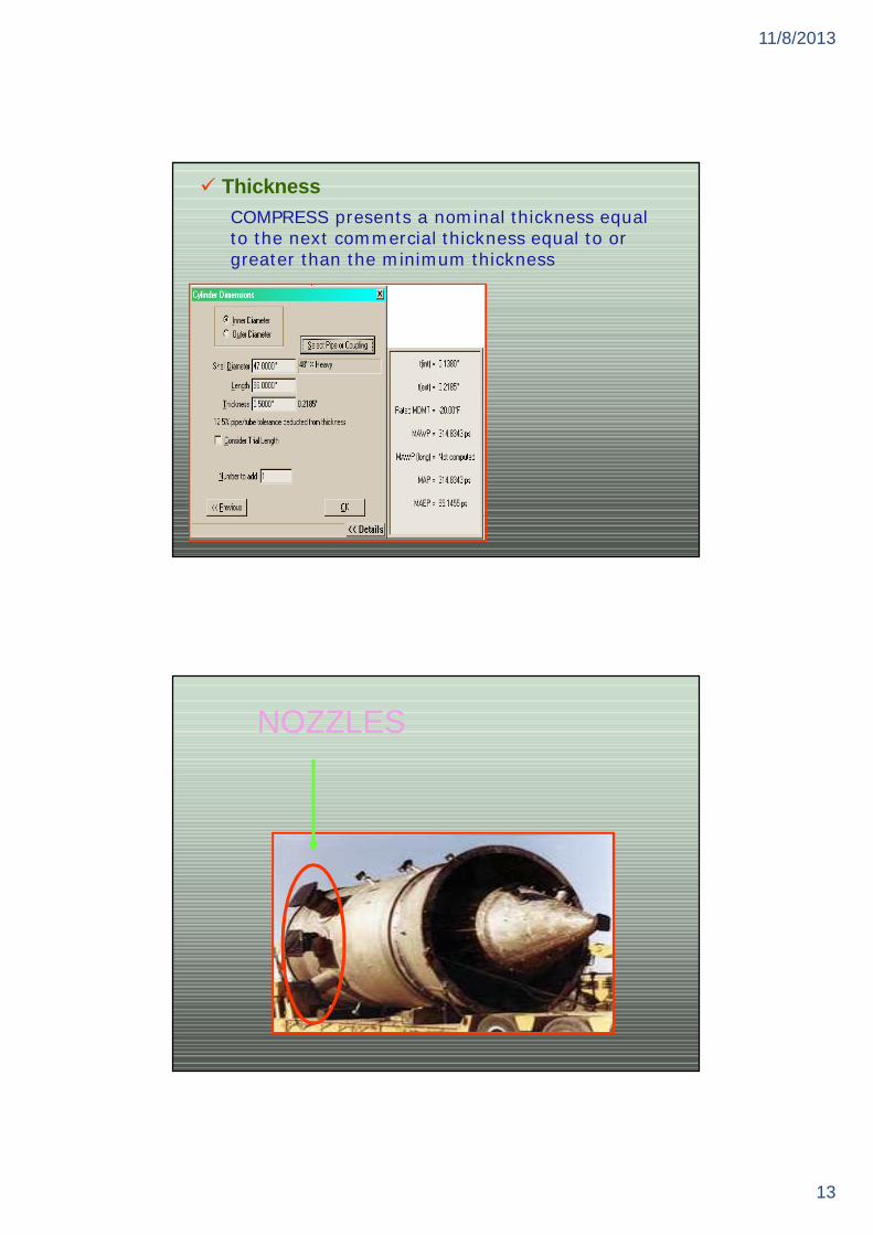
ThicknessCOMPRESS presents a nominal thickness equal to the next commercial thickness equal to or greater than the minimum thickness
NOZZLES

11/8/2013
14
NOZZLES
TYPES OF NOZZLES:
Type 1 Type 2 Type 4 Type 5
Type 9 Type 10 Type 11 Type 12

11/8/2013
15
Type 1 = nozzle with no reinforcement
Type 2 = nozzle with reinforcement
Type 4 = nozzle with reinforcement andinternal projection
Type 9 = large neck thickness of nozzle
Type 10 = large neck thickness of nozzle withinternal projection
Type 11 = Reinforcement with bolting
Radial/Perpendicular/HillsideOn heads
Nozzles may be radial, perpendicular or hillsideRadial perpendicular hillside
On cylindersNozzles may be radial, tilted or offset
Tilted = The maximum tilt angle is 60°

11/8/2013
16
On transitions (conical shape)
Nozzles may be normal, perpendicular or parallel
This is appears when nozzle type is of type 2 or type 4
Pad Material
normal perpendicular parallel
Add ASME B16.5/B16.47 Flange

11/8/2013
17
The ASME B16.5 flange rating is based on the design temperature and internal pressure of the component towhich the nozzle is attached
Blind / Bolted CoverThe class of the blind flange is matched to theadjoining flange
COMPRESS automatically provides the ID andthe wall thickness for FVC (Forged Vesselconnections) while selecting the class, type and specifying the nominal size
If proper nominal size is not indicated than COMPRESS chooses the flange size based on the nozzle diameter
Offset (L)If the nozzle is located on a cylinder or transition, L is the measured from the datum line to the center line of the nozzle flangeIf the nozzle is located on a head, L is measuredFrom datum line to the face of the nozzle flange
Angle (Theta)This angle refers to the plan view position from thetop/left hand side of the nozzle on the vesselScheme for the angle (theta), 0° at 12 o'clock, 90° at 3 o'clock, 180° at 6 o'clock, and 270° at 9 o'clock
11/8/2013
18
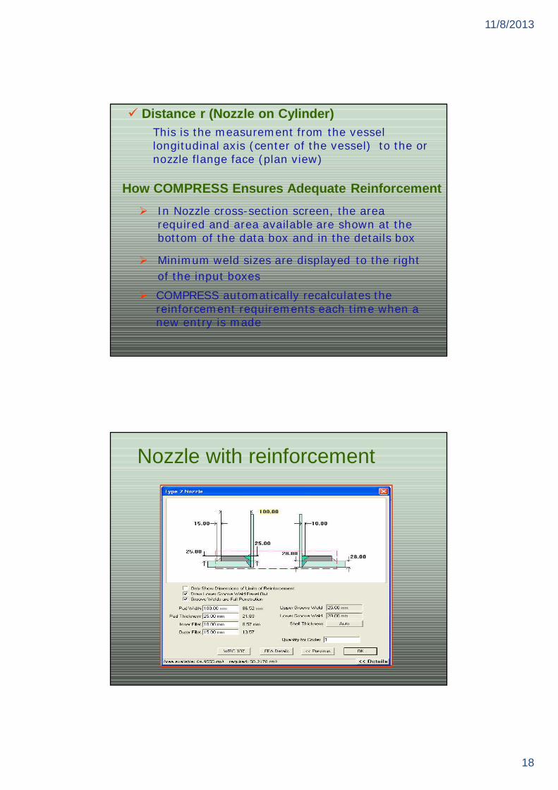
Distance r (Nozzle on Cylinder)This is the measurement from the vessel longitudinal axis (center of the vessel) to the or nozzle flange face (plan view)
How COMPRESS Ensures Adequate ReinforcementIn Nozzle cross-section screen, the area required and area available are shown at the bottom of the data box and in the details box
Minimum weld sizes are displayed to the right of the input boxes
COMPRESS automatically recalculates the reinforcement requirements each time when a new entry is made
Nozzle with reinforcement

11/8/2013
19
Only Show Dimensions of Limits of ReinforcementThe limits of reinforcement are indicated by the red dashed box drawn around the opening
Material outside of the red outline will not contributeto the reinforcing area
WRC-107 LoadingsWRC-107 is the Welding Research Council paper 107This paper describes a method to calculate stresses in the vessel resulting from forces and momentsapplied to an attached nozzle
The loads specified are local loads applied to the nozzle (or clip) and are used in determining local stress

11/8/2013
20
Pr -- Pr is the radial loading on the nozzle
Mc -- Mc is the circumferential moment on the nozzleML -- ML is the longitudinal bending moment on the nozzle
VL -- VL is the longitudinal shear force on the nozzle
Mt -- Mt is the torsion
To define allowable stresses under local stress condition are usually not greater than two thirds of the material yield stress, a design factor of 3.0 is generally recommended
The design factor DOES NOT deal with the issue of stress concentrations at notches and fatigue
Vc -- Vc is the circumferential shear force on the nozzle
Plan View (Nozzle on Head)
This head plan view enables you to quickly assess whether the areas of reinforcement overlap, or whether a nozzle location has been input incorrectly

11/8/2013
21
LimitsThe limit circle around each opening indicates the radial limit of reinforcement used to determinethe available area of reinforcement
Pad
The circular area filled with blue color illustratesthe current pad diameter input
Dish Radius (80%)The green circle indicates approximately where the knuckle region begins on a head For a 2:1 head, the white circle is called the 80%radius
Body FlangeRadial Load on Flange
COMPRESS calculates the local bending moment and overhead weight and determines an equivalent pressure to use for designing

11/8/2013
22
When flanges are attach to a conical section without a knuckle or flare radius, the superposition of the discontinuity stresses is required. COMPRESS calculates the discontinuity stresses
Attached ToIf the flange is attach to a cylindrical shell or transition, then COMPRESS considers this "body" flange to be a line of support (bulkhead) for externalpressure calculations
Gasket DataGasket DescriptionIf a predefined gasket is selected then the 'm‘and 'y' values will be set based on the selection
Rigidity Factor
Suggested values for rigidity factor as listed inAppendix S-2(c) are 0.2 for loose type flangesand 0.3 for integral or optional flange types
If there is a rigidity calculations in design modeCOMPRESS calculates the rigidity index. If therigidity index J>1, COMPRESS increases the flangethickness until a value of J<1 is obtained
Rigidity calculations per Appendix S-2 are usefulfor those cases where leakage is concern

11/8/2013
23
SUPPORTLeg
TYPES OF SUPPORTHORIZONTAL CYLINDER:
Saddle support
VERTICAL CYLINDER:
Leg supportSkirt support

11/8/2013
24
Legs
Effective Length Coeff. (K)one end guided, one end fixed
(K=1)
one end guided, the other end
hinged (K=2)
A recommended value to use for K is 1.5
COMPRESS will not allow a value for K smaller than 1.0
Stress Coefficient (Cm)COMPRESS defaults at a Cm value of 0.85

11/8/2013
25
Overall Leg Length
COMPRESS defaults at 36,000 psi (2531 kg/cm )
Elastic Modulus (E)
COMPRESS defaults at 29 x 10^6 psi (2038902 kg/cm )
Yield Stress (Fy)
The length L extends to thebottom of the base plate
Leg Base to Girth Seam Length
Enter the distance L1 from the bottom of the base plate to the head to shell seam
Reduce Leg Eccentricity toCOMPRESS assumes the axial load on the leg issupported at the outside fiber of the leg
COMPRESS will not accept a negative input
Anchor Bolt TypesMetric bolts may be used even if the English system of units is being used by COMPRESS

11/8/2013
26
Bracing

11/8/2013
27
Bracing Height (h')
Brace Chord Length (C'1)
Vertical Offset Distance (y')
Height of the leg bracing
Horizontal distance
Distance that the center of gravity of the lower weld or fastener group is elevated from the bottom of the base plate

11/8/2013
28
Structure Size AvailableCOMPRESS automatically determines the minimum leg size required and highlights it.
Lugs

11/8/2013
29
Lugs
Lug Allowable Stress
COMPRESS will default to 24,000 psi (1688 kg/cm )
This allowable stress is used when sizing the base plate gussets and top plate
Lug Length (Lt)Length is the distance from the side closest to the vessel to the side farthest from the vessel
Anchor Bolt and Base Plate Design
COMPRESS consider the initial bolt tension

11/8/2013
30
Saddles
Saddles

11/8/2013
31
Saddle Distance from Datum (L)This dimension locates the saddles on the vesselwith respect to the datum line
Wear Plate Thickness (tp)It is recommended that the wear plate thicknessshall not exceed the shell plate thickness
Standard Saddle Details
These are the dimensions included in the COMPRESS library which is same as used in the PIP (Process Industry Practices) Standard
11/8/2013
32
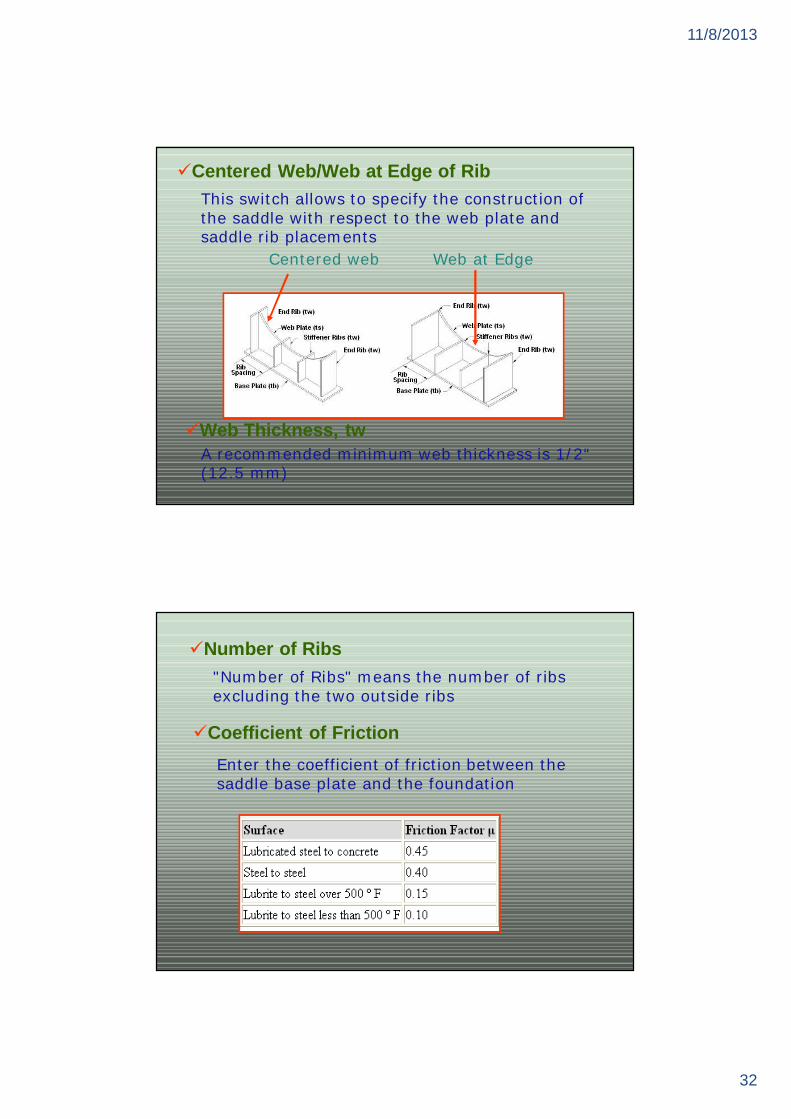
Centered Web/Web at Edge of RibThis switch allows to specify the construction of the saddle with respect to the web plate and saddle rib placements
Web Thickness, twA recommended minimum web thickness is 1/2“ (12.5 mm)
Centered web Web at Edge
Number of Ribs"Number of Ribs" means the number of ribsexcluding the two outside ribs
Coefficient of FrictionEnter the coefficient of friction between the saddle base plate and the foundation

11/8/2013
33
Use MAWP
If the Use MAWP switch is tagged, then the pressure stress will be based on the vesselmaximum allowable working pressure
Add Stiffener Rings
There is also an option to have these ringsact as vacuum rings for the vessel
regular vacuum rings will not be consideredas saddle stiffener rings
Liquid Level Load
The liquid level is the normal level of operating liquid in the vessel. It is NOT the same as hydro test condition (vessel completely full of water or air)
Use Identifier in 3D Sketch
If this is not selected, COMPRESS will use NLL toindicate the nominal liquid level

11/8/2013
34
Platform / Ladder
Platform / Ladder

11/8/2013
35
COMPRESS calculates the center of gravity of the platform and the platform weight, then calculates the eccentric overturning bending moment on the vessel
COMPRESS assumes a worst case scenario when combining eccentric overturning with the momentsresulting from wind and seismic forces
Platform Start Angle, End AngleThese inputs specify the angular position in degrees ofthe platform around the circumference of the vessel
0° is at 12 o'clock, 90° is at 3 o'clock
Ladder Start to DatumCOMPRESS calculates the length of ladder as the difference between the platform to datum and the ladder to datum distances
Shell ClearanceThe distance from the outer diameter of the cylinder (cylinder dimension before insulation) to the inner edge of the platform
Railing WeightIt is consider 1 foot length of railing weight

11/8/2013
36
TraysTray Diameter
The actual diameter of the tray, which may be lessthan the vessel ID
Tray WeightThe weight per square foot of each individual trayin the group
COMPRESS assumes the trays are circular
One Pass/Two PassThis input controls how the trays are depicted in Vessel Drafting Program
Piping

11/8/2013
37
Piping
The weight of the piping and the weight of the liquid contained by the piping is considered in pipingweight calculations
Piping wind loads are considered by changing vesseleffective OD in Codes Menu/Wind
There are two dialog boxes for making data inputfor piping: User Defined and Detailed Geometry
If you want to enter piping weights directly usethe User Defined dialog box
The piping axis is assumed to be parallel to thevessel axisDetailed Geometry, offers help with pipe lookup tables and the ability to specify a pipe as being connected to one of the vessel nozzles.

11/8/2013
38
Benefits of COMPRESS
In COMPRESS as design of vessel progresses it calculates required thickness & graphically displays the results.If opening is too close to the end of the vessel or if the nozzle is close to another nozzle COMPRESS automatically checks for overlapping limits of reinforcement between adjacent nozzles. And give warning if interference are detected.
Benefits ..Component analysis
It is not necessary to model an entire vessel if you want to analyze just one part of an existing vessel.
Broad MATERIAL libraryMaterial properties are in a library holding
entire ASME material, all vaccum charts & elastic modulus data are available.

11/8/2013
39
Benefits …Automatic Report generation
COMPRESS show not only the calculated result but typically also the equation used. Equations indicate code reference number.
Detailed summary are available for each parameter, component and such as nozzle summary, pressure summary, thickness summary, weight summary, vaccum summary, hydro test summary.
Benefits ..
Automatic Report generation

11/8/2013
40
Benefits ..Automatic Report generation
Benefits …Automatic Report generation

11/8/2013
41
Benefits …Automatic Report generation
Benefits …LINKING TO OTHER PROGRAMS
Exchanger work in conjuction with COMPRESS to mechanically design heat exchanger.TEMA / ASME EXCHANGER design heat exchangers according to VII
& VIII edition of the TEMA standard & ASME SEC VIII PART UHX
TEMA and ASME Exchanger calculates governing required tubesheet thickness for up to 8 separate loading conditions such as normal, start up, shut down etc.

11/8/2013
42
Benefits …LINKING TO OTHER PROGRAMS …
We can export the model so it open the door for more detail communication.
Benefits …FLEXIBILITY
COMPRESS can have a flexibility to change parameters like thickness, internal & external pressure, corrosion allowance, hydro test pressure etc.

11/8/2013
43
Benefits …TECHNICAL GUIDELINES
some material require full radiography and COMPRESS guides for the this which is specified in compliance with table UCS-57/UNF-57.In rating mode it automatically forces impact testing on UCS-66 materials for thickness greater than 4in.COMPRESS does not adjust nominal thickness downward if design requirement are reduced.
REFERENCESASME section VIII div.1ASCE 7-88 (formally ANSI A 58.1)Uniform Building Code 1991National Building Code of Canada 1990L.P.Zick (analysis of saddle support)C.E.Freese (Vibration of vertical PV)ASME/ANSI B 16.5-1988 pipe flange and flange fittingsAPI RP 510, second edition(inspection, rating and repair of PV. in
petroleum refinery services)

11/8/2013
44
Pricing for COMPRESS Price for first copy : $ 6000Annual support & : $ 1300Update Service (SUS)
Local Area Network Charge : 30% Extra
THANK YOU.........