Embed Size (px)
Citation preview
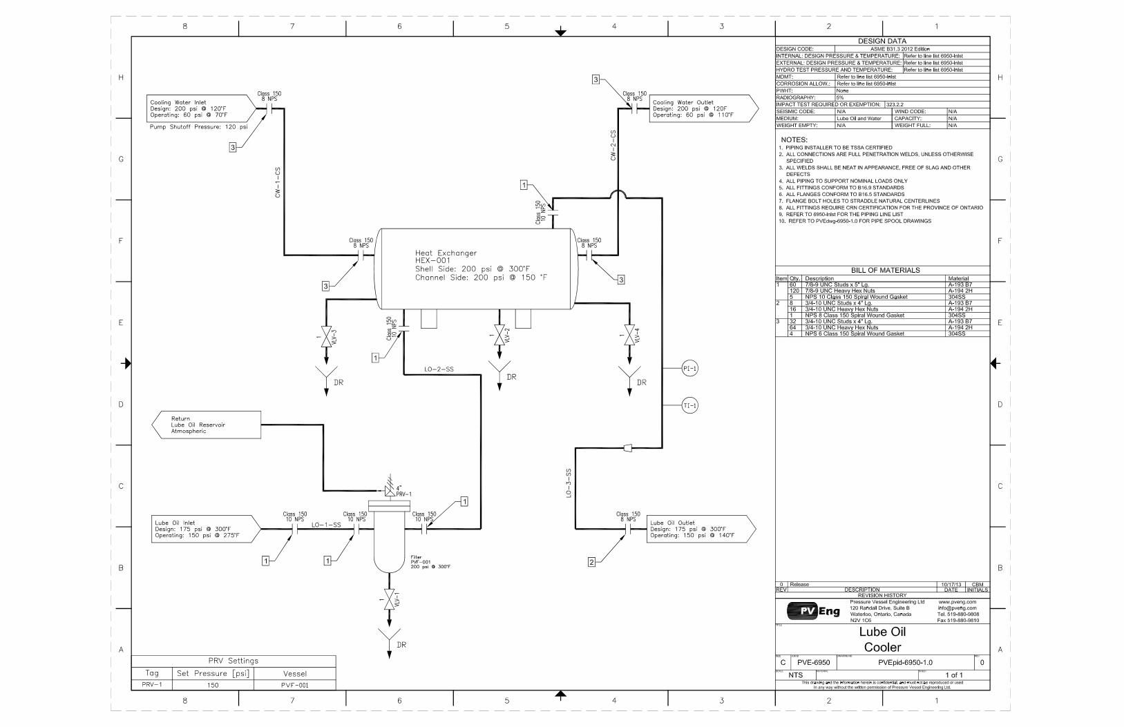

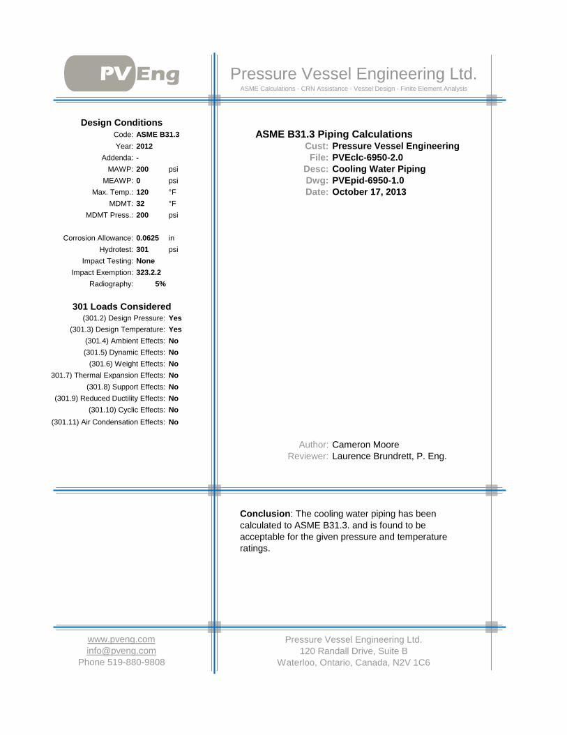
Code: ASME B31.3Year: 2012 Cust: Pressure Vessel Engineering
Addenda: - File: PVEclc-6950-2.0MAWP: 200 psi Desc: Cooling Water Piping
MEAWP: 0 psi Dwg: PVEpid-6950-1.0Max. Temp.: 120 °F Date:
MDMT: 32 °FMDMT Press.: 200 psi
Corrosion Allowance: 0.0625 inHydrotest: 301 psi
Impact Testing: NoneImpact Exemption: 323.2.2
Radiography: 5%
(301.2) Design Pressure: Yes(301.3) Design Temperature: Yes
(301.4) Ambient Effects: No(301.5) Dynamic Effects: No
(301.6) Weight Effects: No(301.7) Thermal Expansion Effects: No
(301.8) Support Effects: No(301.9) Reduced Ductility Effects: No
(301.10) Cyclic Effects: No(301.11) Air Condensation Effects: No
Author: Cameron MooreReviewer: Laurence Brundrett, P. Eng.
301 Loads Considered
Pressure Vessel Engineering Ltd.120 Randall Drive, Suite B
Waterloo, Ontario, Canada, N2V 1C6
Phone 519-880-9808
ASME B31.3 Piping Calculations
Conclusion: The cooling water piping has been calculated to ASME B31.3. and is found to be acceptable for the given pressure and temperature ratings.
October 17, 2013
Pressure Vessel Engineering Ltd.ASME Calculations - CRN Assistance - Vessel Design - Finite Element Analysis
Design Conditions

Table of Contents 17-Oct-13 Page 2 of 6
Description Page Description Page
Cover 1 8 inch Pipe 4Table of Contents 2 8 inch Elbow 5Material Properties 3 Cl 150 Flange 6
ReviewerDrawing:
Calculation Method:Calculation Results:
Rev Date By0 17-Oct-13 CBM
AuthorCBM JLLCBM JLLCBM JLL
Revision(s)Description
Release

1 Material Properties ver 4.09 Page 3 of 62
3 <- Description4
5 Design Pressure:6 200.0 <- P, internal operating pressure at top of vessel (psig)7 0.0 <- mPa, external operation pressure8 Water <- Operating Fluid9 3 <- h, fluid height (ft) 10 1.000 <- rho, fluid density (1.0 for water) 11 Static Head = 0.4331*rho*h = 0.4331 * 1 * 3 sH = 1.312 Design Pressure = P + sH = 200 + 1.3 mDp = 201.313
14 Hydro Test (ASME B31.3-2008 - 345.4.2)15 Test Pressure = 1.5 * mDp * MR - sH = 1.5 * 201.3 * 1 - 1.3 mTp = 30116
17 Material Properties (ASME B31.3 Table A-1)18 120 <- mTemp, design temp ºF Test at ambient temp
19
Where Used Ambient Strength
Design Strength
Strength Ratio
Max ºF Ext Graph
20 Pipe 20000 20000 1.000 110021 Flanges & O-lets 23300 23170 1.006 110022 Elbows 20000 20000 1.000 110045 Min Ratio (MR) = 1.00046
47 Per ASME B16.9, Reducers are calculated as equivalent straight seamless pipe48
49
CS Spec A-105 forgings
Material
CS Spec A-106 Gr-B pipes & tubes
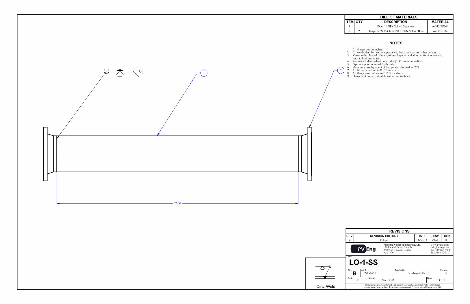
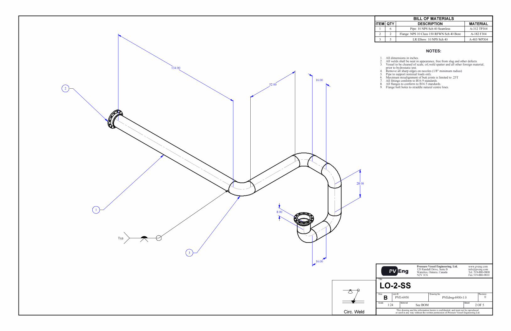
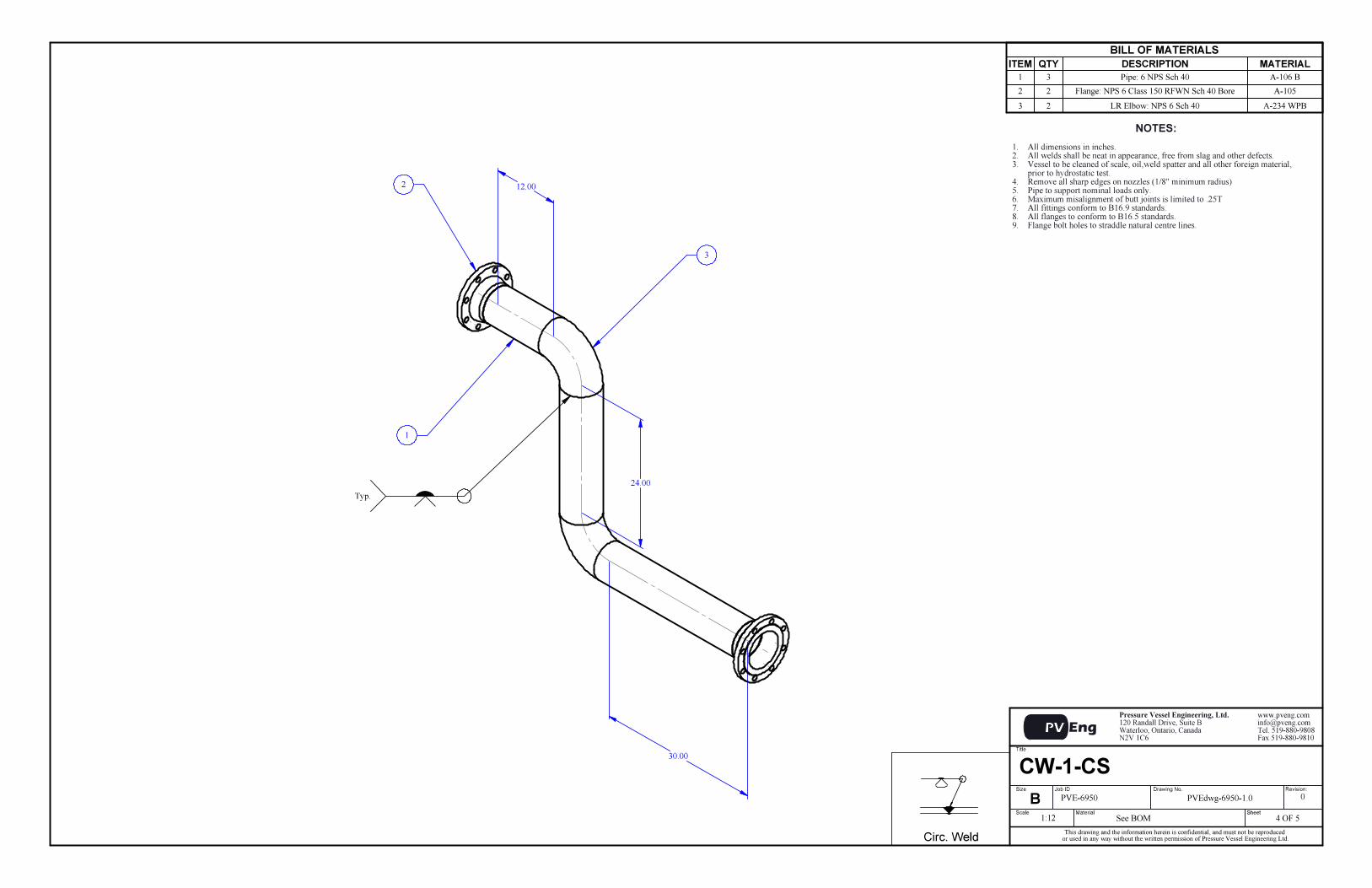
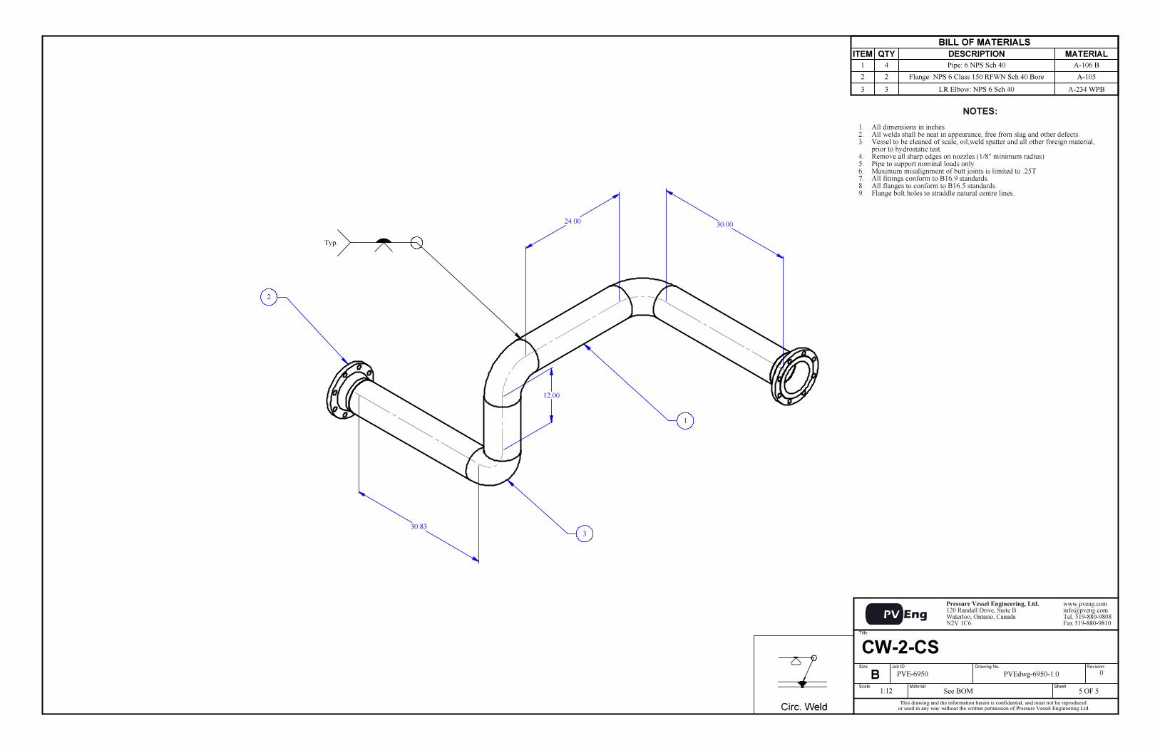
Cooling Water Piping
CS Spec A-234 Gr-WPB forgings

1 B31.3-Pipe ver 6.01 Page 4 of 62 Description
3 Dimensions:4 8.625 D [in] - outside diameter5 0.322 tnom [in] - nominal thickness6 0.000 h [in] - thread allowance B1.20.27 12.500% UT [%] - undertolerance allowance8 0.063 Ca [in] - corrosion allowance9 0.000 Ma [in] - mechanical allowance
10 Material and Conditions:11 FerriticSteel Group - material group12 120 Temp [°F] - design temperature13 Spec A-106 Gr-B Material14 Table211 Table - applicable material group in B16.515 20,000 S [psi] - allowable stress level16 1.00 E - longitudinal efficiency (circ. stress)17 1.00 W - weld joint reduction factor18 201.3 P [psi] - design pressure
19
20 Variables:21 ci [in] = Ma+Ca 0+0.063 = 0.062522 co [in] = h 0 = 0.000023 c [in] = ci+co 0.0625+0 = 0.062524 T [in] = tnom*(1-UT) 0.322*(1-0.125) = 0.281825 d [in] = D-2*T 8.625-2*0.2818 = 8.061526 Y1 = From Table 304.1.1 = 0.4027 Y2 = (d+2*c)/(D+d+2*c) (8.0615+2*0.0625)/(8.625+8.0615+2*0.0625) = 0.487028 Interior Pressure: B31.3-304.1.229 t1 [in] = P*D/(2*(S*E*W+P*Y1)) 201.3*8.625/(2*(20000*1*1+201.3*0.4)) = 0.043230 t2 [in] = P*D/(2*(S*E*W+P*Y2)) 201.3*8.625/(2*(20000*1*1+201.3*0.487)) = 0.043231 t [in] = if(t1>=D/6,t2,t1) IF(0.0432>=8.625/6,0.0432,0.0432) = 0.043232 tm [in] = t+c 0.0432+0.0625 = 0.105733 CheckT = T >= tm 0.2818 >= 0.1057 = Acceptable
8 inch Pipe
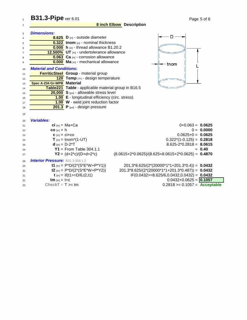
1 B31.3-Pipe ver 6.01 Page 5 of 62 Description
3 Dimensions:4 8.625 D [in] - outside diameter5 0.322 tnom [in] - nominal thickness6 0.000 h [in] - thread allowance B1.20.27 12.500% UT [%] - undertolerance allowance8 0.063 Ca [in] - corrosion allowance9 0.000 Ma [in] - mechanical allowance
10 Material and Conditions:11 FerriticSteel Group - material group12 120 Temp [°F] - design temperature13 Spec A-234 Gr-WPB Material14 Table221 Table - applicable material group in B16.515 20,000 S [psi] - allowable stress level16 1.00 E - longitudinal efficiency (circ. stress)17 1.00 W - weld joint reduction factor18 201.3 P [psi] - design pressure
19
20 Variables:21 ci [in] = Ma+Ca 0+0.063 = 0.062522 co [in] = h 0 = 0.000023 c [in] = ci+co 0.0625+0 = 0.062524 T [in] = tnom*(1-UT) 0.322*(1-0.125) = 0.281825 d [in] = D-2*T 8.625-2*0.2818 = 8.061526 Y1 = From Table 304.1.1 = 0.4027 Y2 = (d+2*c)/(D+d+2*c) (8.0615+2*0.0625)/(8.625+8.0615+2*0.0625) = 0.487028 Interior Pressure: B31.3-304.1.229 t1 [in] = P*D/(2*(S*E*W+P*Y1)) 201.3*8.625/(2*(20000*1*1+201.3*0.4)) = 0.043230 t2 [in] = P*D/(2*(S*E*W+P*Y2)) 201.3*8.625/(2*(20000*1*1+201.3*0.487)) = 0.043231 t [in] = if(t1>=D/6,t2,t1) IF(0.0432>=8.625/6,0.0432,0.0432) = 0.043232 tm [in] = t+c 0.0432+0.0625 = 0.105733 CheckT = T >= tm 0.2818 >= 0.1057 = Acceptable
8 inch Elbow
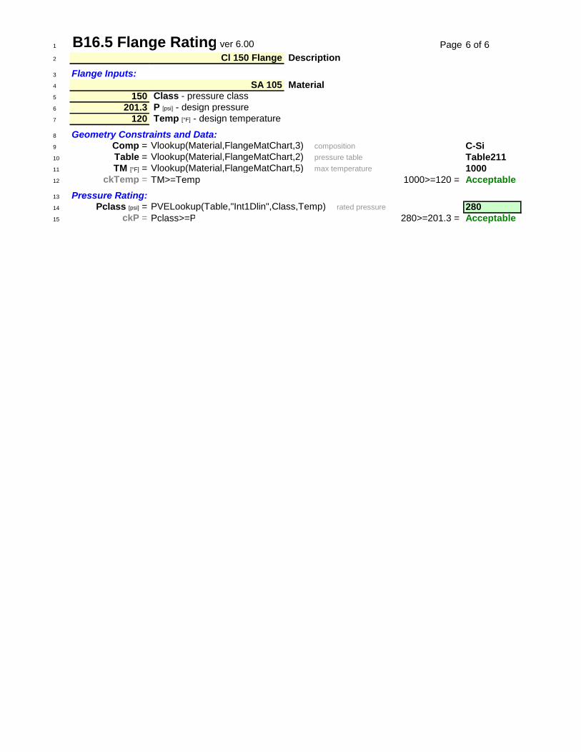
1 B16.5 Flange Rating ver 6.00 Page 6 of 62 Description3 Flange Inputs:4 Material5 150 Class - pressure class6 201.3 P [psi] - design pressure7 120 Temp [°F] - design temperature
8 Geometry Constraints and Data:9 Comp = Vlookup(Material,FlangeMatChart,3)~~composition C-Si10 Table = Vlookup(Material,FlangeMatChart,2)~~pressure table Table21111 TM [°F] = Vlookup(Material,FlangeMatChart,5)~~max temperature 100012 ckTemp = TM>=Temp 1000>=120 = Acceptable13 Pressure Rating:14 Pclass [psi] = PVELookup(Table,"Int1Dlin",Class,Temp)~~rated pressure 28015 ckP = Pclass>=P 280>=201.3 = Acceptable
Cl 150 Flange
SA 105


![SECTION 15180 - Los Alamos National Laboratory€¦ · Web viewFittings: Black steel, ASTM A234, butt welding type, ASME B16.9, [and/or], ASTM A197, ASME B16.3 malleable threaded](https://img.pdfslide.net/doc/110x75/5e9e42f053acc35edd70117b/section-15180-los-alamos-national-laboratory-web-view-fittings-black-steel-astm.jpg)