Embed Size (px)
Citation preview
1
Vidyalankar T.Y. B.Sc. (IT) : Sem. VI Internet Technologies
Time : 2½ Hrs. Prelim Question Paper Solution Marks : 75
Q.1 Attempt any TWO question of the following : [10]Q.1(a) Find the netid of the following IP address :
(i) 114.34.2.8 (ii) 132.56.8.6 (iii)208.34.54.12 (iv) 251.34.98.5 (v) 129.14.6.8
[5]
(A) (i) 114.34.2.8 Net id: 114 (ii) 132.56.8.6 Net id: 132.56 (iii) 208.34.54.12 Net id: 208.34.54 (iv) 251.34.98.5 Class E ; No Net id (v) 129.14.6.8 Net id: 129.14 Q.1(b) List and explain the fields of IP datagram used for fragmentation. [5](A) The fields that are related to fragmentation and reassembly of an IP datagram are the
identification, flags, and fragmentation offset fields. Identification : This 16-bit field identifies a datagram originating from the source host. The
combination of the identification and source IP address must uniquely define a datagram as it leaves the source host. To guarantee uniqueness, the IP protocol uses a counter to label the datagrams. The counter is initialized to a positive number. When the IP protocol sends a datagram, it copies the current value of the counter to the identification field and increments the counter by one. As long as the counter is kept in the main memory, uniqueness is guaranteed. When a datagram is fragmented, the value in the identification field is copied into all fragments. In other words, all fragments have the same identification number, which is also the same as the original datagram. The identification number helps the destination in reassembling the datagram. It knows that all fragments having the same identification value should be assembled into one datagram.
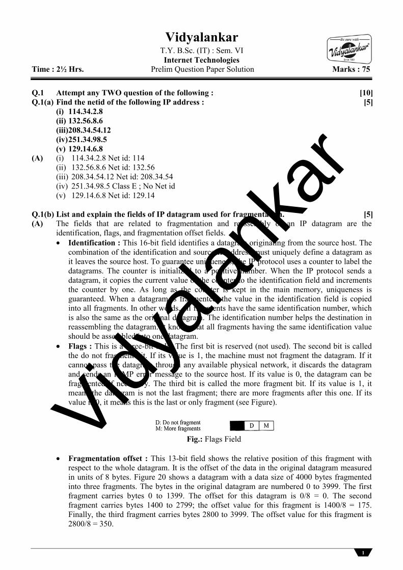
Flags : This is a three-bit field. The first bit is reserved (not used). The second bit is called the do not fragment bit. If its value is 1, the machine must not fragment the datagram. If it cannot pass the datagram through any available physical network, it discards the datagram and sends an ICMP error message to the source host. If its value is 0, the datagram can be fragmented if necessary. The third bit is called the more fragment bit. If its value is 1, it means the datagram is not the last fragment; there are more fragments after this one. If its value is 0, it means this is the last or only fragment (see Figure).
Fig.: Flags Field
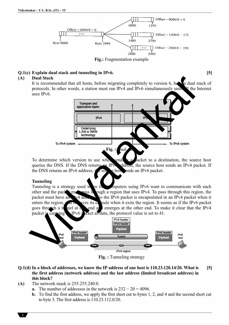
Fragmentation offset : This 13-bit field shows the relative position of this fragment with
respect to the whole datagram. It is the offset of the data in the original datagram measured in units of 8 bytes. Figure 20 shows a datagram with a data size of 4000 bytes fragmented into three fragments. The bytes in the original datagram are numbered 0 to 3999. The first fragment carries bytes 0 to 1399. The offset for this datagram is 0/8 = 0. The second fragment carries bytes 1400 to 2799; the offset value for this fragment is 1400/8 = 175. Finally, the third fragment carries bytes 2800 to 3999. The offset value for this fragment is 2800/8 = 350.
Vidyala
nkar
Vidyalankar : T.Y. B.Sc. (IT) IT
2
Fig.: Fragmentation example
Q.1(c) Explain dual stack and tunneling in IPv6. [5](A) Dual Stack It is recommended that all hosts, before migrating completely to version 6, have a dual stack of
protocols. In other words, a station must run IPv4 and IPv6 simultaneously until all the Internet uses IPv6.
Fig. : Dual stack
To determine which version to use when sending a packet to a destination, the source host queries the DNS. If the DNS returns an IPv4 address, the source host sends an IPv4 packet. If the DNS returns an IPv6 address, the source host sends an IPv6 packet.
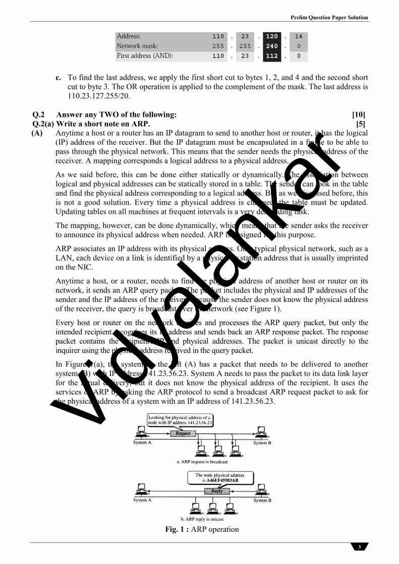
Tunneling Tunneling is a strategy used when two computers using IPv6 want to communicate with each
other and the packet must pass through a region that uses IPv4. To pass through this region, the packet must have an IPv4 address. So the IPv6 packet is encapsulated in an IPv4 packet when it enters the region, and it leaves its capsule when it exits the region. It seems as if the IPv6 packet goes through a tunnel at one end and emerges at the other end. To make it clear that the IPv4 packet is carrying an IPv6 packet as data, the protocol value is set to 41.
Fig. : Tunneling strategy
Q.1(d) In a block of addresses, we know the IP address of one host is 110.23.120.14/20. What is
the first address (network address) and the last address (limited broadcast address) inthis block?
[5]
(A) The network mask is 255.255.240.0. a. The number of addresses in the network is 232 − 20 = 4096. b. To find the first address, we apply the first short cut to bytes 1, 2, and 4 and the second short cut
to byte 3. The first address is 110.23.112.0/20.
Vidyala
nkar
Prelim Question Paper Solution
3
c. To find the last address, we apply the first short cut to bytes 1, 2, and 4 and the second short cut to byte 3. The OR operation is applied to the complement of the mask. The last address is 110.23.127.255/20.
Q.2 Answer any TWO of the following: [10]Q.2(a) Write a short note on ARP. [5](A) Anytime a host or a router has an IP datagram to send to another host or router, it has the logical
(IP) address of the receiver. But the IP datagram must be encapsulated in a frame to be able to pass through the physical network. This means that the sender needs the physical address of the receiver. A mapping corresponds a logical address to a physical address.
As we said before, this can be done either statically or dynamically. The association between logical and physical addresses can be statically stored in a table. The sender can look in the table and find the physical address corresponding to a logical address. But as we discussed before, this is not a good solution. Every time a physical address is changed, the table must be updated. Updating tables on all machines at frequent intervals is a very demanding task.
The mapping, however, can be done dynamically, which means that the sender asks the receiver to announce its physical address when needed. ARP is designed for this purpose.
ARP associates an IP address with its physical address. On a typical physical network, such as a LAN, each device on a link is identified by a physical or station address that is usually imprinted on the NIC.
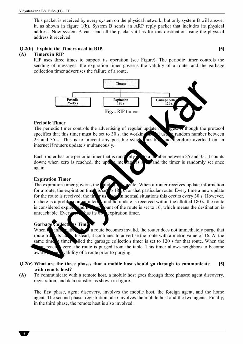
Anytime a host, or a router, needs to find the physical address of another host or router on its network, it sends an ARP query packet. The packet includes the physical and IP addresses of the sender and the IP address of the receiver. Because the sender does not know the physical address of the receiver, the query is broadcast over the network (see Figure 1).
Every host or router on the network receives and processes the ARP query packet, but only the intended recipient recognizes its IP address and sends back an ARP response packet. The response packet contains the recipient's IP and physical addresses. The packet is unicast directly to the inquirer using the physical address received in the query packet.
In Figure 1(a), the system on the left (A) has a packet that needs to be delivered to another system (B) with IP address 141.23.56.23. System A needs to pass the packet to its data link layer for the actual delivery, but it does not know the physical address of the recipient. It uses the services of ARP by asking the ARP protocol to send a broadcast ARP request packet to ask for the physical address of a system with an IP address of 141.23.56.23.
Fig. 1 : ARP operation
Vidyala
nkar
Vidyalankar : T.Y. B.Sc. (IT) IT
4
This packet is received by every system on the physical network, but only system B will answer it, as shown in figure 1(b). System B sends an ARP reply packet that includes its physical address. Now system A can send all the packets it has for this destination using the physical address it received.
Q.2(b) Explain the Timers used in RIP. [5](A) Timers in RIP RIP uses three times to support its operation (see Figure). The periodic timer controls the
sending of messages, the expiration timer governs the validity of a route, and the garbage collection timer advertises the failure of a route.
Fig. : RIP timers
Periodic Timer The periodic timer controls the advertising of regular update messages. Although the protocol
specifies that this timer must be set to 30 s. the working model uses a random number between 25 and 35 s. This is to prevent any possible synchronization and therefore overload on an internet if routers update simultaneously.
Each router has one periodic timer that is randomly set to a number between 25 and 35. It counts
down; when zero is reached, the update message is sent, and the timer is randomly set once again.
Expiration Timer The expiration timer governs the validity of a route. When a router receives update information
for a route, the expiration timer is set to 180 s for that particular route. Every time a new update for the route is received, the timer us reset. In normal situations this occurs every 30 s. However, if there is a problem on an internet and no update is received within the allotted 180 s, the route is considered expired and the hop count of the route is set to 16, which means the destination is unreachable. Every route has its own expiration timer.
Garbage Collections Timer When the information about a route becomes invalid, the router does not immediately purge that
route from its table. Instead, it continues to advertise the route with a metric value of 16. At the same time, a timer called the garbage collection timer is set to 120 s for that route. When the count reaches zero, the route is purged from the table. This timer allows neighbors to become aware of the invalidity of a route prior to purging.
Q.2(c) What are the three phases that a mobile host should go through to communicate
with remote host? [5]
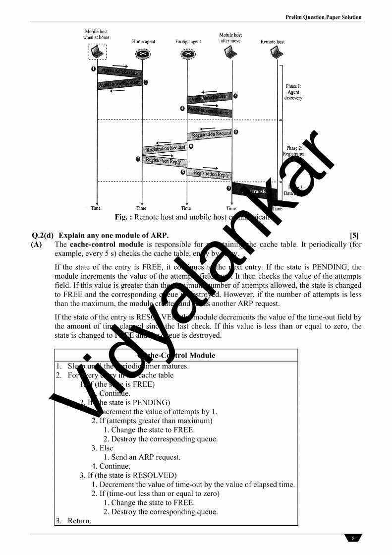
(A) To communicate with a remote host, a mobile host goes through three phases: agent discovery, registration, and data transfer, as shown in figure.
The first phase, agent discovery, involves the mobile host, the foreign agent, and the home
agent. The second phase, registration, also involves the mobile host and the two agents. Finally, in the third phase, the remote host is also involved.
Vidyala
nkar
Prelim Question Paper Solution
5
Fig. : Remote host and mobile host communication
Q.2(d) Explain any one module of ARP. [5](A) The cache-control module is responsible for maintaining the cache table. It periodically (for
example, every 5 s) checks the cache table, entry by entry.
If the state of the entry is FREE, it continues to the next entry. If the state is PENDING, the module increments the value of the attempts field by 1. It then checks the value of the attempts field. If this value is greater than the maximum number of attempts allowed, the state is changed to FREE and the corresponding queue is destroyed. However, if the number of attempts is less than the maximum, the module creates and sends another ARP request.
If the state of the entry is RESOLVED, the module decrements the value of the time-out field by the amount of time elapsed since the last check. If this value is less than or equal to zero, the state is changed to FREE and the queue is destroyed.
Cache-Control Module 1. Sleep until the periodic timer matures. 2. For every entry in the cache table 1. If (the state is FREE) 1. Continue. 2. If (the state is PENDING) 1. Increment the value of attempts by 1. 2. If (attempts greater than maximum) 1. Change the state to FREE. 2. Destroy the corresponding queue. 3. Else 1. Send an ARP request. 4. Continue. 3. If (the state is RESOLVED) 1. Decrement the value of time-out by the value of elapsed time. 2. If (time-out less than or equal to zero) 1. Change the state to FREE. 2. Destroy the corresponding queue. 3. Return.
Vidyala
nkar
Vidyalankar : T.Y. B.Sc. (IT) IT
6
Q.3 Answer any TWO of the following: [10]Q.3(a) Explain the concept of Silly Window Syndrome Problem by sender in TCP and give
its solution . [5]
(A) Syndrome Created by the Sender The sending TCP may create a silly window syndrome if it is serving an application program
that creates data slowly, for example, 1 byte at a time. The application program writes 1 byte at a time into the buffer of the sending TCP. If the sending TCP does not have any specific instructions, it may create segments containing 1 byte of data. The result is a lot of 41-byte segments that are traveling through an internet.
The solution is to prevent the sending TCP from sending the data byte by byte. The sending TCP must be forced to wait as it collects data to send in a larger block. How long should the sending TCP wait? If it waits too long, it may delay the process. If it does not wait long enough, it may end up sending small segments. Nagle found an elegant solution.
Nagle’s Algorithm Nagle’s algorithm is very simple, but it solves the problem. This algorithm is for the sending TCP: (i) The sending TCP sends the first piece of data it receives from the sending application
program even if it is only 1 byte. (ii) After sending the first segment, the sending TCP accumulates data in the output buffer and
waits until either the receiving TCP sends an acknowledgment or until enough data has accumulated to fill a maximum-size segment. At this time, the sending TCP can send the segment.
(iii) Step 2 is repeated for the rest of the transmission. Segment 3 must be sent if an acknowledgment is received for segment 2 or enough data is accumulated to fill a maximum-size segment.
The elegance of Nagle's algorithm is in its simplicity and in the fact that it takes into account the speed of the application program that creates the data and the speed of the network that transports the data. If the application program is faster than the network, the segments are larger (maximum-size segments). If the application program is slower than the network, the segments are smaller (less than the maximum segment size).
Q.3(b) Describe the 3 Way handshake used for Connection Establishment in TCP. [5](A) The connection establishment described above is called three-way handshaking. In this
procedure, an application program, called the client, wants to make a connection with another application program, called the server, using TCP as the transport layer protocol.
The three-way handshaking procedure starts with the server. The server program tells its TCP that it is ready to accept a connection. This is called a request for a passive opqn. Although the server TCP is ready to accept any connection from any machine in the world it cannot make the connection itself.
The client program makes a request for an active open. A client that wishes to connect to a server tells its TCP that it needs to be connected to a particular server. The TCP can now start the three-way handshaking process as shown in Figure.
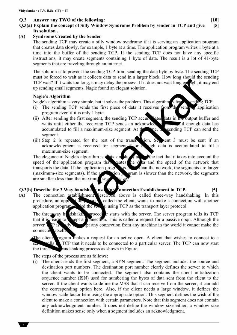
The steps of the process are as follows: (i) The client sends the first segment, a SYN segment. The segment includes the source and
destination port numbers. The destination port number clearly defines the server to which the client wants to be connected. The segment also contains the client initialization sequence number (ISN) used for numbering the bytes of data sent from the client to the server. If the client wants to define the MSS that it can receive from the server, it can add the corresponding option here. Also, if the client needs a large window, it defines the window scale factor here using the appropriate option. This segment defines the wish of the client to make a connection with certain parameters. Note that this segment does not contain any acknowledgment number. It does not define the window size either; a window size definition makes sense only when a segment includes an acknowledgment.
Vidyala
nkar
Prelim Question Paper Solution
7
(ii) The server sends the second segment, a SYN and ACK segment. This segment has a dual purpose. First, it acknowledges the receipt of the first segment using the ACK flag and acknowledgment number field. The acknowledgment number is the client initialization sequence number plus one. The server must also define the client window size. Second, the segment is used as the initialization segment for the server. It contains the initialization sequence number used to number the bytes sent from the server to the client. It also contains the window scale factor option (if needed) to be used by the server and the MSS defined by the server. As we said before, this is two segments combined into one.
(iii) The client sends the third segment. This is just an ACK segment. It acknowledges the receipt of the second segment using the ACK flag and acknowledgment number field. The acknowledgment number is the server initialization sequence number plus one. The client must also define the server window size. Note that data can be sent with the third packet.
A rare situation may occur when both processes issue an active open. In this case, both TCPs transmit a SYN + ACK segment to each other and one single connection is established between them.
Connection Termination Any of the two parties involved in exchanging data (client or server) can close the connection.
When connection in one direction is terminated, the other party can continue sending data in the other direction. Therefore, four actions are needed to close the connections in both directions:
(i) Host A sends a FIN segment announcing its wish for connection termination. (ii) Host B sends a segment acknowledging (confirming) the request of A. After this, the
connection is closed in one direction, but not in the other. Host B can continue sending data to A.
(iii) When host B has finished sending its own data, it sends a FIN segment to indicate that it wants to close the connection.
(iv) Host A acknowledges (confirms) the request of B. This implies four steps. We cannot combine steps 2 and 3 here as we did in connection
establishment. Steps 2 and 3 may or may not happen at the same time. The connection may be closed in one direction, but left open in the other direction.
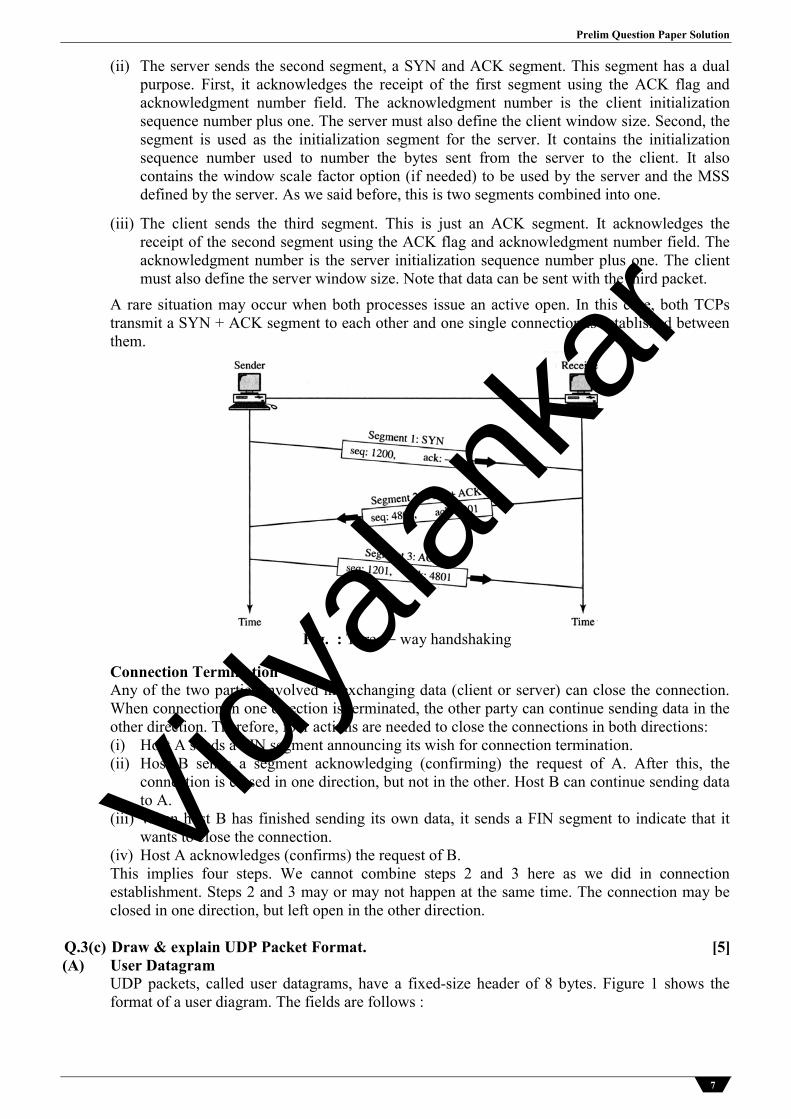
Q.3(c) Draw & explain UDP Packet Format. [5](A) User Datagram UDP packets, called user datagrams, have a fixed-size header of 8 bytes. Figure 1 shows the
format of a user diagram. The fields are follows :
Fig. : Three way handshaking
Vidyala
nkar
Vidyalankar : T.Y. B.Sc. (IT) IT
8
Fig. 1: User datagram format
Source port number This is the port number used by the process running on the source host. It is 16 bits long,
which means that the port number can range from 0 to 65,535. If the source host is the client (a client sending a request), the port number, in most cases, is an ephemeral port number requested by the process and chosen by the UDP software running on the source host. If the source host is the server (a server sending a response), the port number, in most cases, is a well-known port number.
Destination port number This is the port number used by the process running on the destination host. It is also 16 bits
long. If the destination host is the server (a client sending a request), the port number, in most cases, is a well-known port number. If the destination host is the client (a server sending a response), the port number, in most cases, is an ephemeral port number. In this case, the server copies the ephemeral port number it has received in the request packet.
Length This is a 16-bit field that defines the total length of the user datagram, header plus data. The
16 bits can define a total length of 0 to 65,535 bytes. However, the total length needs to be much less because a UDP user datagram is stored in an IP datagram with the total length of 65,535 bytes. The length field in a UDP user datagram is actually not necessary. A user datagram is encapsulated in an IP datagram. There is a field in the IP datagram that defines the total length. There is another field in the IP datagram that defines the length of the header. So if we subtract the value of the second field from the first, we can deduce the length of the UDP datagram that is encapsulated in an IP datagram.
UDP length = IP length - IP header's length
However, the designers of the UDP protocol felt that it was more efficient for the destination UDP to calculate the length of the data from the information provided in the UDP user datagram rather than ask the IP software to supply this information. We should remember that when the IP software delivers the UDP user datagram to the UDP layer, it has already dropped the IP header.
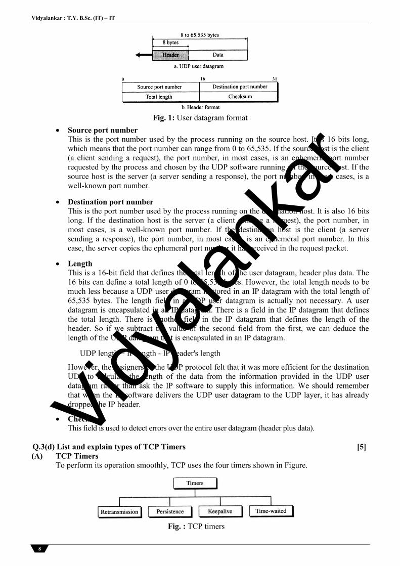
Checksum This field is used to detect errors over the entire user datagram (header plus data). Q.3(d) List and explain types of TCP Timers [5](A) TCP Timers To perform its operation smoothly, TCP uses the four timers shown in Figure. Fig. : TCP timers
Vidyala
nkar
Prelim Question Paper Solution
9
Retransmission Timer To control a lost or discarded segment, TCP employs a retransmission timer that handles the
retransmission time, the waiting time for an acknowledgment of a segment. When TCP sends a segment, it creates a retransmission timer for that particular segment. Two situations may occur : (i) If an acknowledgment is received for this particular segment before the timer goes off,
the timer is destroyed. (ii) If the timer goes off before the acknowledgment arrives, the segment is retransmitted and
the timer is reset. Persistence Timer To deal with the zero window-size advertisement, TCP needs another timer. Suppose the
receiving TCP announces a window size of zero. The sending TCP then stops transmitting segments until the receiving TCP sends an acknowledgment announcing a nonzero window size. This acknowledgment can be lost. Remember that acknowledgments are not acknowledged in TCP. If this acknowledgment is lost, the receiving TCP thinks that it has done its job and waits for the sending TCP to send more segments. The sending TCP has not received an acknowledgment and waits for the other TCP to send an acknowledgment advertising the size of the window. Both TCPs can continue to wait for each other forever and result in deadlock.
To correct this deadlock, TCP uses a persistence timer for each connection. When the
sending TCP receives an acknowledgment with a window size of zero, it starts a persistence timer. When the persistence timer goes off, the sending TCP sends a special segment called a probe. This segment contains only 1 byte of data. It has a sequence number, but its never acknowledged; it is even ignored in calculating the sequence number for the rest of the data. The probe alerts the receiving TCP that the acknowledgment was lost and should be resent.
The value of the persistence timer is set to the value of the retransmission time. However, if a response is not received from the receiver, another probe segment is sent and the value of the persistence timer is doubled and reset. The sender continues sending the probe segments and doubling and resetting the value of the persistence timer until the value reaches a threshold (usually 60 s). After that the sender sends one probe segment every 60 s until the window is reopened.
Keepalive Timer A keepalive timer is used in some implementations to prevent a long idle connection
between two TCPs. Suppose that a client opens a TCP connection to a server, transfers some data, and becomes silent. Perhaps the client has crashed. In this case, the connection remains open forever.
To remedy this situation, most implementations equip a server with a keepalive timer. Each
time the server hears from a client, it resets this timer. The time-out is usually two hours. If the server does not hear from the client after two hours, it sends a probe segment. If there is no response after 10 probes, each of which is 75 s apart, it assumes that the client is down and terminates the connection.
Time Waited Timer The time-waited timer is used during connection termination. When TCP closes a con-
nection, it does not consider the connection really closed. The connection is held in limbo for a time-waited period (see Figure 27). This allows duplicate FIN segments, if any, to arrive at the destination to be discarded. The value for this timer is usually two times the expected lifetime of a segment.
Vidyala
nkar
Vidyalankar : T.Y. B.Sc. (IT) IT
10
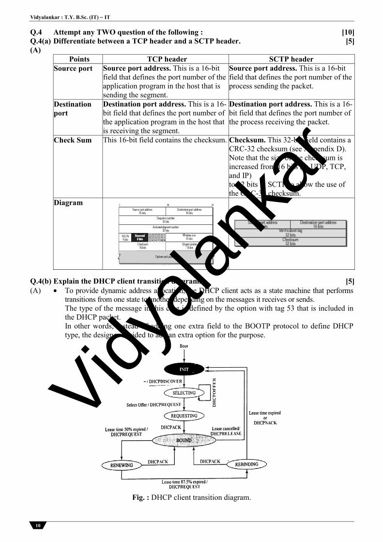
Q.4 Attempt any TWO question of the following : [10]Q.4(a) Differentiate between a TCP header and a SCTP header. [5](A)
Points TCP header SCTP header Source port Source port address. This is a 16-bit
field that defines the port number of the application program in the host that is sending the segment.
Source port address. This is a 16-bit field that defines the port number of the process sending the packet.
Destination port
Destination port address. This is a 16-bit field that defines the port number of the application program in the host that is receiving the segment.
Destination port address. This is a 16-bit field that defines the port number of the process receiving the packet.
Check Sum This 16-bit field contains the checksum. Checksum. This 32-bit field contains a CRC-32 checksum (see Appendix D). Note that the size of the checksum is increased from 16 bits (in UDP, TCP, and IP) to 32 bits in SCTP to allow the use of the CRC-32 checksum.
Diagram
Q.4(b) Explain the DHCP client transition diagram. [5](A) To provide dynamic address allocation, the DHCP client acts as a state machine that performs
transitions from one state to another depending on the messages it receives or sends. The type of the message in this case is defined by the option with tag 53 that is included in
the DHCP packet. In other words, instead of adding one extra field to the BOOTP protocol to define DHCP
type, the designer decided to add an extra option for the purpose.
Fig. : DHCP client transition diagram.
Vidyala
nkar
Prelim Question Paper Solution
11
INIT State The client broadcasts a DHCPDISCOVER message. SELECTING State Those servers that can provide this type of service respond with a DHCPDISCOVER message.
In these messages, the servers offer an IP address. They can also offer the lease duration. The default is 1 hour. The server that sends a DHCPOFFER locks the offered IP address so that it is not available to any other clients.
REQUESTING State The client remains in the requesting state until it receives a DHCPACK message from the server
that creates the biding between the client physical address and its IP address. After receipt of the DHCPACK, the client goes to the bound state.
BOUND State In this state, the client can use the IP address until the lease expires. When 50 percent of the
lease period is reached, the client sends another DHCPREQUEST to ask for renewal. RENEWING State The client remains in the renewing state until one of two events happens. It can receive a
DHCPACK, which renews the lease agreement. REBINDING State The client remains in the rebinding state until one of three events happens. If the client receives
a DHCPNACK or the lease expires, it goes back to the initializing state and tries to get another IP address. If the client receives a DHCPACK, it goes to the bound state and resets the timer.
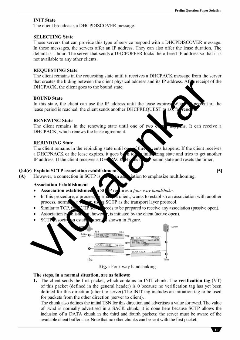
Q.4(c) Explain SCTP association establishment. [5](A) However, a connection in SCTP is called an association to emphasize multihoming.
Association Establishment Association establishment in SCTP requires a four-way handshake. In this procedure, a process, normally a client, wants to establish an association with another
process, normally a server, using SCTP as the transport layer protocol. Similar to TCP, the SCTP server needs to be prepared to receive any association (passive open). Association establishment, however, is initiated by the client (active open). SCTP association establishment is shown in Figure.
Fig. : Four-way handshaking
The steps, in a normal situation, are as follows: 1. The client sends the first packet, which contains an INIT chunk. The verification tag (VT)
of this packet (defined in the general header) is 0 because no verification tag has yet been defined for this direction (client to server).The INIT tag includes an initiation tag to be used for packets from the other direction (server to client). The chunk also defines the initial TSN for this direction and advertises a value for rwnd. The value of rwnd is normally advertised in a SACK chunk; it is done here because SCTP allows the inclusion of a DATA chunk in the third and fourth packets; the server must be aware of the available client buffer size. Note that no other chunks can be sent with the first packet.
Vidyala
nkar
Vidyalankar : T.Y. B.Sc. (IT) IT
12
2. The server sends the second packet, which contains an INIT ACK chunk. The verification tag is the value of the initial tag field in the INIT chunk. This chunk initiates the tag to be used in the other direction, defines the initial TSN, for data flow from server to client, and sets the servers’ rwnd. The value of rwnd is defined to allow the client to send a DATA chunk with the third packet. The INIT ACK also sends a cookie that defines the state of the server at this moment.
3. The client sends the third packet, which includes a COOKIE ECHO chunk. This is a very simple chunk that echoes, without change, the cookie sent by the server. SCTP allows the inclusion of data chunks in this packet.
4. The server sends the fourth packet, which includes the COOKIE ACK chunk that acknowledges the receipt of the COOKIE ECHO chunk. SCTP allows the inclusion of data chunks with this packet.
Q.4(d) Explain the features of Stream Control Transmission Protocol. [5](A) SCTP Features Transmission Sequence Number (TSN) The unit of data in TCP is a byte. Data transfer in TCP is controlled by numbering bytes
using a sequence number. On the other hand, the unit of data in SCTP is a data chunk, which may or may not have a
one-to-one relationship with the message coming from the process because of fragmentation. Data transfer in SCTP is controlled by numbering the data chunks. SCTP uses a transmission sequence number (TSN) to number the data chunks. In other words, the TSN in SCTP plays the analogous role as the sequence number in TCP. TSNs are 32 bits long and randomly initialized between 0 and 232 - 1. Each data chunk must
carry the corresponding TSN in its header. In SCTP, a data chunk is numbered using a TSN.
Stream Identifier (SI) In TCP, there is only one stream in each connection. In SCTP, there may be several streams in each association. Each stream in SCTP needs to be
identified using a stream identifier (SI). Each data chunk must carry the SI in its header so that when it arrives at the destination, it
can be properly placed in its stream. The SI is a 16-bit number starting from 0. To distinguish between different streams, SCTP uses an SI.
Stream Sequence Number (SSN) When a data chunk arrives at the destination SCTP, it is delivered to the appropriate stream
and in the proper order. This means that, in addition to an SI, SCTP defines each data chunk in each stream with a
stream sequence number (SSN). To distinguish between different data chunks belonging to the same stream, SCTP uses
SSNs.
Packets In TCP, a segment carries data and control information. Data are carried as a collection of bytes; control information is defined by six control flags in
the header. The design of SCTP is totally different: data are carried as data chunks, control information
as control chunks. Several control chunks and data chunks can be packed together in a packet. A packet in SCTP plays the same role as a segment in TCP. Figure 2 compares a segment in
TCP and a packet in SCTP. TCP has segments; SCTP has packets.
Vidyala
nkar
Prelim Question Paper Solution
13
Acknowledgment Number TCP acknowledgment numbers are byte-oriented and refer to the sequence numbers. SCTP acknowledgment numbers are chunk-oriented. They refer to the TSN. A second difference between TCP and SCTP acknowledgments is the control information.
This information is part of the segment header in TCP. In SCTP, acknowledgment numbers are used to acknowledge only data chunks; control
chunks are acknowledged by other control chunks if necessary. Flow Control SCTP implements flow control to avoid overwhelming the receiver. Error Control SCTP implements error control to provide reliability. TSN numbers and acknowledgment
numbers are used for error control. Congestion Control SCTP implements congestion control to determine how many data chunks can be injected
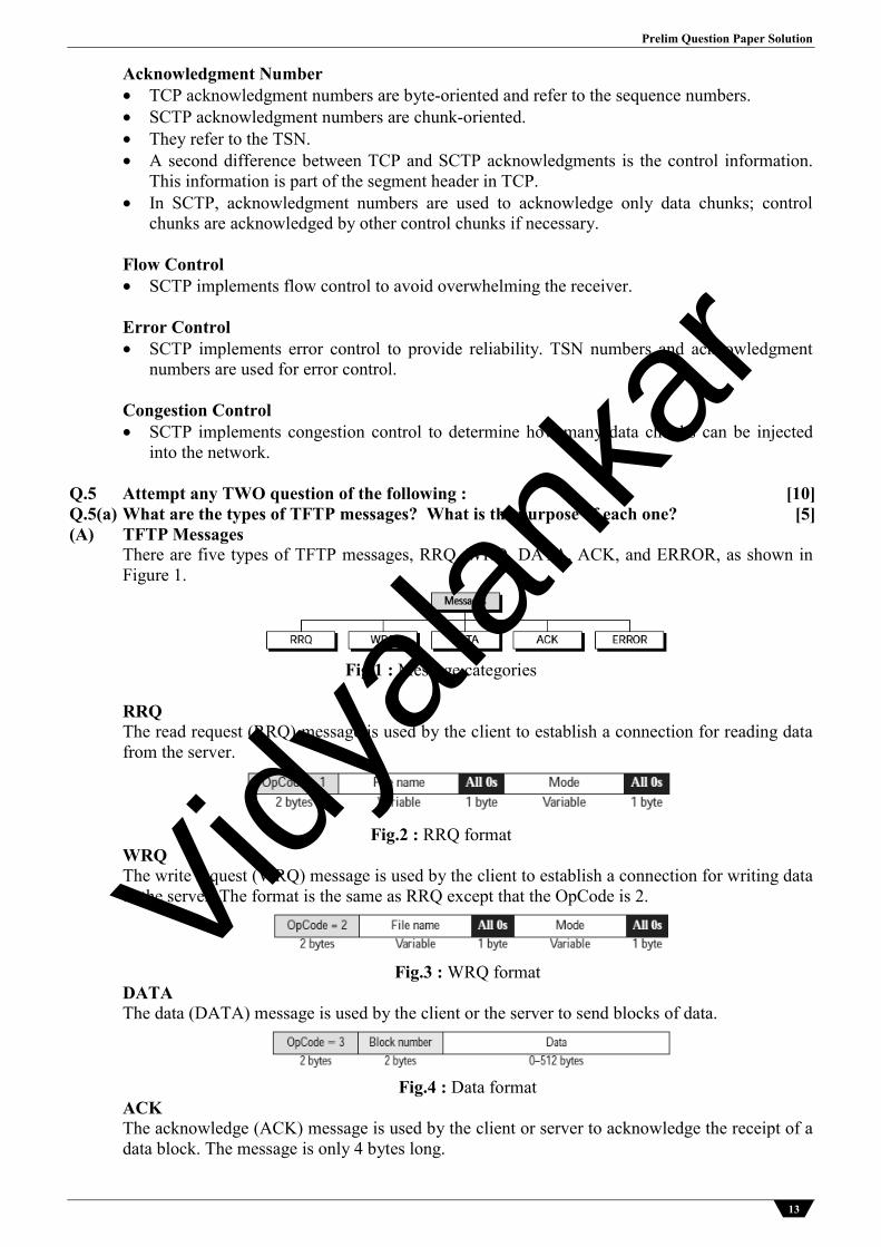
into the network. Q.5 Attempt any TWO question of the following : [10]Q.5(a) What are the types of TFTP messages? What is the purpose of each one? [5](A) TFTP Messages
There are five types of TFTP messages, RRQ, WRQ, DATA, ACK, and ERROR, as shown in Figure 1.
Fig.1 : Message categories
RRQ The read request (RRQ) message is used by the client to establish a connection for reading data from the server.
Fig.2 : RRQ format
WRQ The write request (WRQ) message is used by the client to establish a connection for writing data to the server. The format is the same as RRQ except that the OpCode is 2.
Fig.3 : WRQ format
DATA The data (DATA) message is used by the client or the server to send blocks of data.
Fig.4 : Data format
ACK The acknowledge (ACK) message is used by the client or server to acknowledge the receipt of a data block. The message is only 4 bytes long.
Vidyala
nkar
Vidyalankar : T.Y. B.Sc. (IT) IT
14
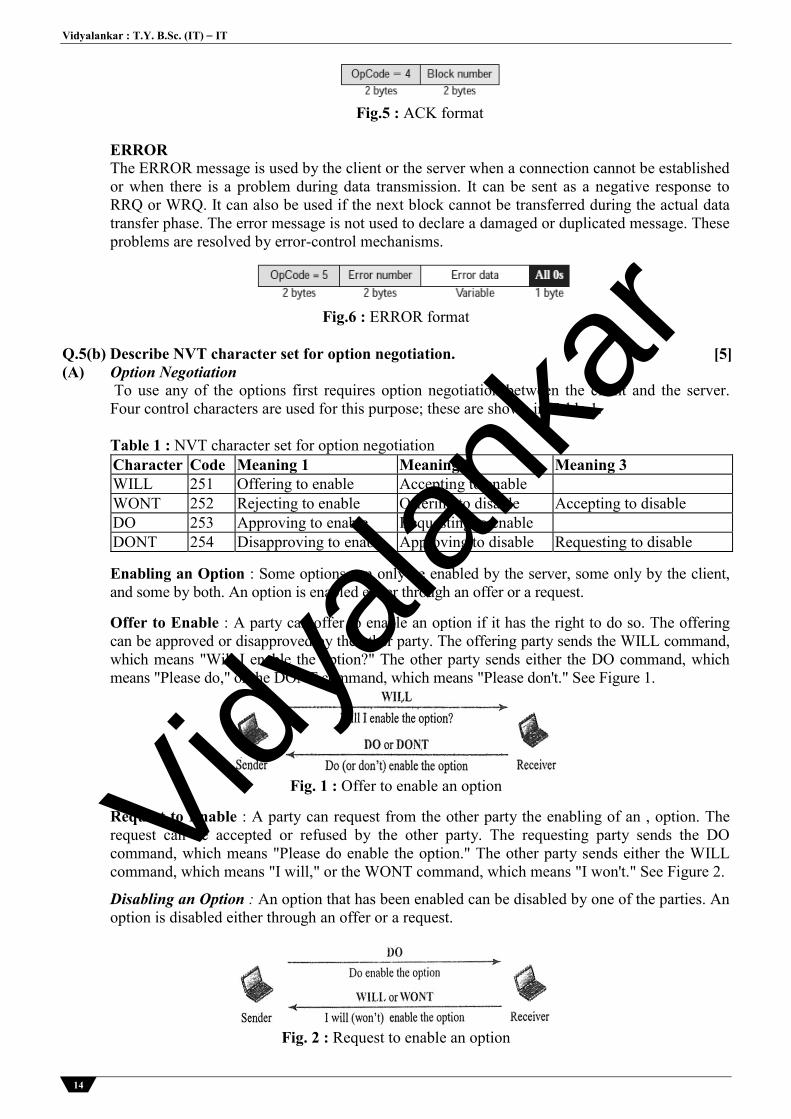
Fig.5 : ACK format
ERROR The ERROR message is used by the client or the server when a connection cannot be established or when there is a problem during data transmission. It can be sent as a negative response to RRQ or WRQ. It can also be used if the next block cannot be transferred during the actual data transfer phase. The error message is not used to declare a damaged or duplicated message. These problems are resolved by error-control mechanisms.
Fig.6 : ERROR format
Q.5(b) Describe NVT character set for option negotiation. [5](A) Option Negotiation To use any of the options first requires option negotiation between the client and the server.
Four control characters are used for this purpose; these are shown in Table 1. Table 1 : NVT character set for option negotiation
Character Code Meaning 1 Meaning 2 Meaning 3 WILL 251 Offering to enable Accepting to enable WONT 252 Rejecting to enable Offering to disable Accepting to disable DO 253 Approving to enable Requesting to enable DONT 254 Disapproving to enable Approving to disable Requesting to disable
Enabling an Option : Some options can only be enabled by the server, some only by the client, and some by both. An option is enabled either through an offer or a request.
Offer to Enable : A party can offer to enable an option if it has the right to do so. The offering can be approved or disapproved by the other party. The offering party sends the WILL command, which means "Will I enable the option?" The other party sends either the DO command, which means "Please do," or the DONT command, which means "Please don't." See Figure 1.
Fig. 1 : Offer to enable an option
Request to Enable : A party can request from the other party the enabling of an , option. The request can be accepted or refused by the other party. The requesting party sends the DO command, which means "Please do enable the option." The other party sends either the WILL command, which means "I will," or the WONT command, which means "I won't." See Figure 2.
Disabling an Option : An option that has been enabled can be disabled by one of the parties. An option is disabled either through an offer or a request.
Fig. 2 : Request to enable an option
Vidyala
nkar
Prelim Question Paper Solution
15
Offer to Disable : A party can offer to disable an option. The other party must approve the offering; it cannot be disapproved. The offering party sends the WONT command, which means "I won't use this option anymore." The answer must be the DONT command, which means "Don't use it anymore." Figure 3 shows an offer to disable an option.
Fig. 3 : Offer to disable an option
Request to Disable : A party can request from another party the disabling of an option. The other party must accept the request; it cannot be rejected. The requesting party sends the DONT command, which means "Please don't use this option anymore." The answer must be the WONT command, which means "I won't use it anymore." Figure 4 shows a request to disable an option.
Fig. 4 : Request to disable an option
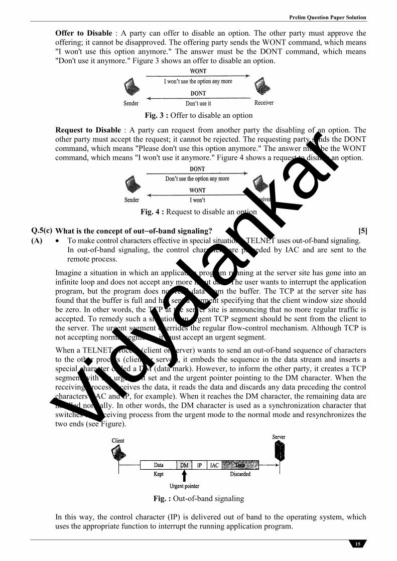
Q.5(c) What is the concept of outof-band signaling? [5](A) To make control characters effective in special situations, TELNET uses out-of-band signaling. In out-of-band signaling, the control characters are preceded by IAC and are sent to the
remote process.
Imagine a situation in which an application program running at the server site has gone into an infinite loop and does not accept any more input data. The user wants to interrupt the application program, but the program does not read data from the buffer. The TCP at the server site has found that the buffer is full and has sent a segment specifying that the client window size should be zero. In other words, the TCP at the server site is announcing that no more regular traffic is accepted. To remedy such a situation, an urgent TCP segment should be sent from the client to the server. The urgent segment overrides the regular flow-control mechanism. Although TCP is not accepting normal segments, it must accept an urgent segment.
When a TELNET process (client or server) wants to send an out-of-band sequence of characters to the other process (client or server), it embeds the sequence in the data stream and inserts a special character called a DM (data mark). However, to inform the other party, it creates a TCP segment with the urgent bit set and the urgent pointer pointing to the DM character. When the receiving process receives the data, it reads the data and discards any data preceding the control characters (IAC and IP, for example). When it reaches the DM character, the remaining data are handled normally. In other words, the DM character is used as a synchronization character that switches the receiving process from the urgent mode to the normal mode and resynchronizes the two ends (see Figure).
Fig. : Out-of-band signaling
In this way, the control character (IP) is delivered out of band to the operating system, which
uses the appropriate function to interrupt the running application program.
Vidyala
nkar
Vidyalankar : T.Y. B.Sc. (IT) IT
16
Q.5(d) Write a note on cookies used with HTTP. [5](A) Cookies used with HTTP : Using Cookies : When a client sends a request to a server, the browser looks in the cookie
directory to see if it can find a cookie sent by that server. If found, the cookie is included in the request. When the server receives the request, it knows that this is an old client, not a new one. Note that the contents of the cookie are never read by the browser or disclosed to the user. It is a cookie made by the server and eaten by the server. Now let us see how a cookie is used for the four previously mentioned purposes:
(1) An electronic store (e-commerce) can use a cookie for its client shoppers. When a client selects an item and inserts it into a cart, a cookie that contains information about the item, such as its number and unit price, is sent to the browser. If the client selects a second item, the cookie is updated with the new selection information. And so on. When the client finishes shopping and wants to check out, the last cookie is retrieved and the total charge is calculated.
(2) The site that restricts access to registered clients only sends a cookie to the client when the client registers for the first time. For any repeated access, only those clients that send the appropriate cookie are allowed.
(3) A Web portal uses the cookie in a similar way. When a user selects her favorite pages, a cookie is made and sent. If the site is accessed again, the cookie is sent to the server to show what the client is looking for.
(4) A cookie is also used by advertising agencies. An advertising agency can place banner ads on some main website that is often visited by users. The advertising agency supplies only a URL that gives the banner address instead of the banner itself. When a user visits the main website and clicks the icon of an advertised corporation, a request is sent to the advertising agency. The advertising agency sends the banner, a GIF file for example, but it also includes a cookie with the ID of the user. Any future use of the banners adds to the database that profiles the Web behavior of the user. The advertising agency has compiled the interests of the user and can sell this information to other parties. This use of cookies has made them very controversial. Hopefully, some new regulations will be devised to preserve the privacy of users.
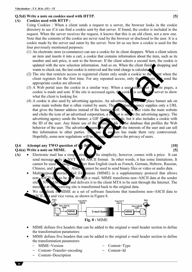
Q.6 Attempt any TWO question of the following : [10]Q.6(a) Write a note on MIME. [5](A) Electronic mail has a simple structure. Its simplicity, however, comes with a price. It can
send message only in NVT 7bit ASCII format. In other words, it has some limitations. It cannot be used for languages other than English (such as French, German, Hebrew, Russian, Chinese, and Japanese). Also, it cannot be used to send binary files or video or audio data.
Multipurpose Internet Mail Extensions (MIME) is a supplementary protocol that allows nonASCII data to be sent through email. MIME transforms nonASCII data at the sender site to NVT ASCII data and delivers it to the client MTA to be sent through the Internet. The message at the receiving site is transformed back to the original data.
We can think of MIME as a set of software functions that transforms nonASCII data to ASCII data and vice versa, as shown in Figure 8.
Fig. 8 : MIME
MIME defines five headers that can be added to the original email header section to define the transformation parameters:
MIME defines five headers that can be added to the original email header section to define the transformation parameters:
MIMEVersion ContentType ContentTransferencoding ContentId ContentDescription
Vidyala
nkar
Prelim Question Paper Solution
17
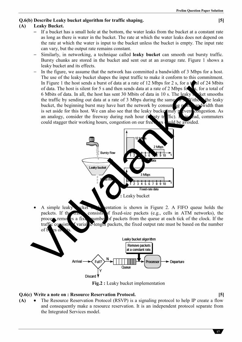
Q.6(b) Describe Leaky bucket algorithm for traffic shaping. [5](A) Leaky Bucket. If a bucket has a small hole at the bottom, the water leaks from the bucket at a constant rate
as long as there is water in the bucket. The rate at which the water leaks does not depend on the rate at which the water is input to the bucket unless the bucket is empty. The input rate can vary, but the output rate remains constant.
Similarly, in networking, a technique called leaky bucket can smooth out bursty traffic. Bursty chunks are stored in the bucket and sent out at an average rate. Figure 1 shows a leaky bucket and its effects.
In the figure, we assume that the network has committed a bandwidth of 3 Mbps for a host. The use of the leaky bucket shapes the input traffic to make it conform to this commitment. In Figure 1 the host sends a burst of data at a rate of 12 Mbps for 2 s, for a total of 24 Mbits of data. The host is silent for 5 s and then sends data at a rate of 2 Mbps for 3 s, for a total of 6 Mbits of data. In all, the host has sent 30 Mbits of data in 10 s. The leaky bucket smooths the traffic by sending out data at a rate of 3 Mbps during the same 10 s. Without the leaky bucket, the beginning burst may have hurt the network by consuming more bandwidth than is set aside for this host. We can also see that the leaky bucket may prevent congestion. As an analogy, consider the freeway during rush hour (bursty traffic). If, instead, commuters could stagger their working hours, congestion on our freeways could be avoided.
Fig. 1 : Leaky bucket
A simple leaky bucket implementation is shown in Figure 2. A FIFO queue holds the
packets. If the traffic consists of fixed-size packets (e.g., cells in ATM networks), the process removes a fixed number of packets from the queue at each tick of the clock. If the traffic consists of variable-length packets, the fixed output rate must be based on the number of bytes or bits.
Fig.2 : Leaky bucket implementation
Q.6(c) Write a note on : Resource Reservation Protocol. [5](A) The Resource Reservation Protocol (RSVP) is a signaling protocol to help IP create a flow
and consequently make a resource reservation. It is an independent protocol separate from the Integrated Services model.
Vidyala
nkar
Vidyalankar : T.Y. B.Sc. (IT) IT
18
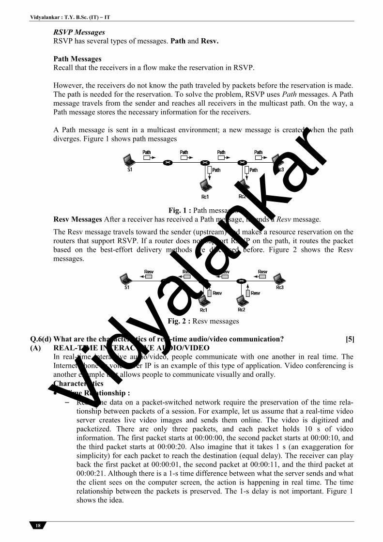
RSVP Messages RSVP has several types of messages. Path and Resv. Path Messages Recall that the receivers in a flow make the reservation in RSVP. However, the receivers do not know the path traveled by packets before the reservation is made. The path is needed for the reservation. To solve the problem, RSVP uses Path messages. A Path message travels from the sender and reaches all receivers in the multicast path. On the way, a Path message stores the necessary information for the receivers. A Path message is sent in a multicast environment; a new message is created when the path diverges. Figure 1 shows path messages
Fig. 1 : Path messages
Resv Messages After a receiver has received a Path message, it sends a Resv message.
The Resv message travels toward the sender (upstream) and makes a resource reservation on the routers that support RSVP. If a router does not support RSVP on the path, it routes the packet based on the best-effort delivery methods we discussed before. Figure 2 shows the Resv messages.
Fig. 2 : Resv messages
Q.6(d) What are the characteristics of real-time audio/video communication? [5](A) REAL-TIME INTERACTIVE AUDIO/VIDEO
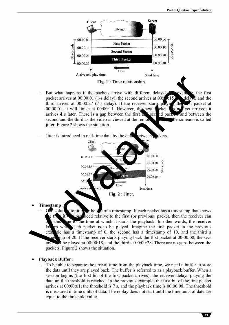
In real-time interactive audio/video, people communicate with one another in real time. The Internet phone or voice over IP is an example of this type of application. Video conferencing is another example that allows people to communicate visually and orally. Characteristics Time Relationship : Real-time data on a packet-switched network require the preservation of the time rela-
tionship between packets of a session. For example, let us assume that a real-time video server creates live video images and sends them online. The video is digitized and packetized. There are only three packets, and each packet holds 10 s of video information. The first packet starts at 00:00:00, the second packet starts at 00:00:10, and the third packet starts at 00:00:20. Also imagine that it takes 1 s (an exaggeration for simplicity) for each packet to reach the destination (equal delay). The receiver can play back the first packet at 00:00:01, the second packet at 00:00:11, and the third packet at 00:00:21. Although there is a 1-s time difference between what the server sends and what the client sees on the computer screen, the action is happening in real time. The time relationship between the packets is preserved. The 1-s delay is not important. Figure 1 shows the idea.
Vidyala
nkar
Prelim Question Paper Solution
19
Fig. 1 : Time relationship.
But what happens if the packets arrive with different delays? For example, the first
packet arrives at 00:00:01 (1-s delay), the second arrives at 00:00:15 (5-s delay), and the third arrives at 00:00:27 (7-s delay). If the receiver starts playing the first packet at 00:00:01, it will finish at 00:00:11. However, the next packet has not yet arrived; it arrives 4 s later. There is a gap between the first and second packets and between the second and the third as the video is viewed at the remote site. This phenomenon is called jitter. Figure 2 shows the situation.
Jitter is introduced in real-time data by the delay between packets.
Fig. 2 : Jitter.
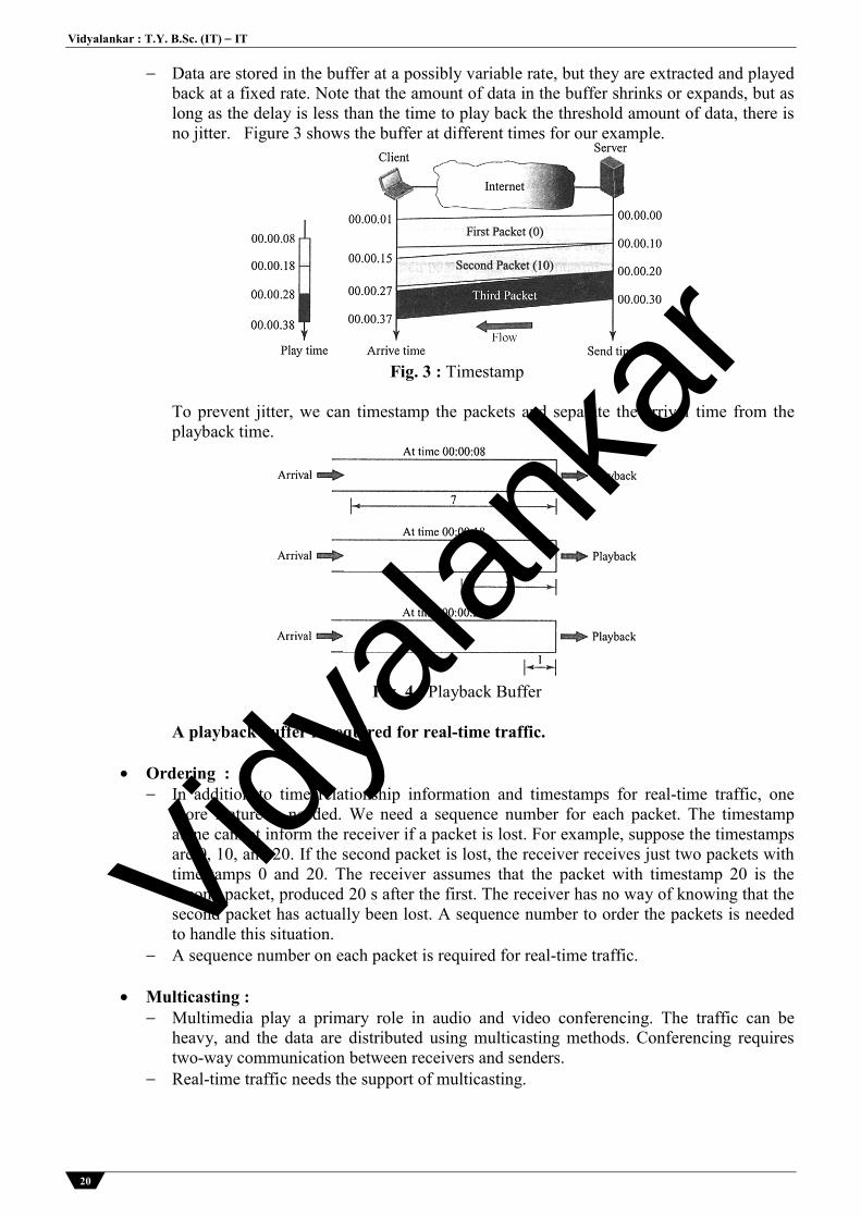
Timestamp : One solution to jitter is the use of a timestamp. If each packet has a timestamp that shows
the time it was produced relative to the first (or previous) packet, then the receiver can add this time to the time at which it starts the playback. In other words, the receiver knows when each packet is to be played. Imagine the first packet in the previous example has a timestamp of 0, the second has a timestamp of 10, and the third a timestamp of 20. If the receiver starts playing back the first packet at 00:00:08, the sec-ond will be played at 00:00:18, and the third at 00:00:28. There are no gaps between the packets. Figure 2 shows the situation.
Playback Buffer : To be able to separate the arrival time from the playback time, we need a buffer to store
the data until they are played back. The buffer is referred to as a playback buffer. When a session begins (the first bit of the first packet arrives), the receiver delays playing the data until a threshold is reached. In the previous example, the first bit of the first packet arrives at 00:00:01; the threshold is 7 s, and the playback time is 00:00:08. The threshold is measured in time units of data. The replay does not start until the time units of data are equal to the threshold value.
Vidyala
nkar
Vidyalankar : T.Y. B.Sc. (IT) IT
20
Data are stored in the buffer at a possibly variable rate, but they are extracted and played back at a fixed rate. Note that the amount of data in the buffer shrinks or expands, but as long as the delay is less than the time to play back the threshold amount of data, there is no jitter. Figure 3 shows the buffer at different times for our example.
Fig. 3 : Timestamp
To prevent jitter, we can timestamp the packets and separate the arrival time from the
playback time.
Fig. 4 : Playback Buffer
A playback buffer is required for real-time traffic. Ordering : In addition to time relationship information and timestamps for real-time traffic, one
more feature is needed. We need a sequence number for each packet. The timestamp alone cannot inform the receiver if a packet is lost. For example, suppose the timestamps are 0, 10, and 20. If the second packet is lost, the receiver receives just two packets with timestamps 0 and 20. The receiver assumes that the packet with timestamp 20 is the second packet, produced 20 s after the first. The receiver has no way of knowing that the second packet has actually been lost. A sequence number to order the packets is needed to handle this situation.
A sequence number on each packet is required for real-time traffic. Multicasting : Multimedia play a primary role in audio and video conferencing. The traffic can be
heavy, and the data are distributed using multicasting methods. Conferencing requires two-way communication between receivers and senders.
Real-time traffic needs the support of multicasting.
Vidyala
nkar
Prelim Question Paper Solution
21
Translation : Sometimes real-time traffic needs translation. A translator is a computer that can change
the format of a high-bandwidth video signal to a lower-quality narrow-bandwidth signal. This is needed, for example, for a source creating a high-quality video signal at 5 Mbps and sending to a recipient having a bandwidth of less than 1 Mbps. To receive the signal, a translator is needed to decode the signal and encode it again at a lower quality that needs less bandwidth.
Translation means changing the encoding of a payload to a lower quality to match the bandwidth of the receiving network.
Mixing : If there is more than one source that can send data at the same time (as in a video or
audio conference), the traffic is made of multiple streams. To converge the traffic to one stream, data from different sources can be mixed. A mixer mathematically adds signals coming from different sources to create one single signal.
Mixing means combining several streams of traffic into one stream. Support from Transport Layer Protocol : TCP is not suitable for interactive traffic. It has no provision for timestamping, and it oes
not support multicasting. However, it does provide ordering (sequence numbers). One feature of TCP that makes it particularly unsuitable for interactive traffic is its error
control mechanism. In interactive traffic, we cannot allow the retransmission of a lost or corrupted packet. If a packet is lost or corrupted in interactive traffic, it must just be ignored. Retransmission upsets the whole idea of timestamping and playback. Today there is so much redundancy in audio and video signals (even with compression) that we can simply ignore a lost packet. The listener or viewer at the remote site may not even notice it.
TCP, with all its sophistication, is not suitable for interactive multimedia traffic because we cannot allow retransmission of packets.
UDP is more suitable for interactive multimedia traffic. UDP supports multicasting and has no retransmission strategy. However, UDP has no provision for timestamping, sequencing, or mixing. A new transport protocol, Real-Time Transport Protocol (RTP), provides these missing features.
UDP is more suitable than TCP for interactive traffic. However, we need the services of RTP, another transport layer protocol, to make up for the deficiencies of UDP.
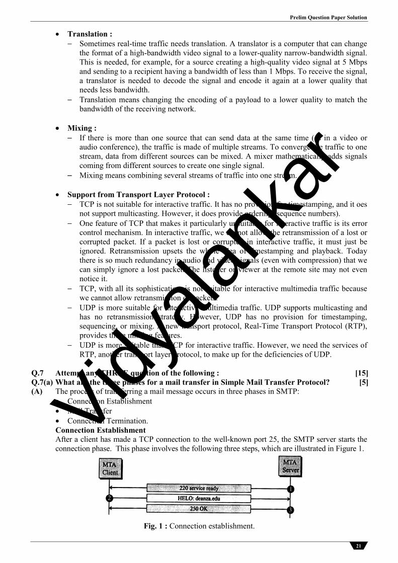
Q.7 Attempt any THREE question of the following : [15]Q.7(a) What are the three phases for a mail transfer in Simple Mail Transfer Protocol? [5](A) The process of transferring a mail message occurs in three phases in SMTP: Connection Establishment Mail Transfer Connection Termination. Connection Establishment After a client has made a TCP connection to the well-known port 25, the SMTP server starts the
connection phase. This phase involves the following three steps, which are illustrated in Figure 1.
Fig. 1 : Connection establishment.
Vidyala
nkar
Vidyalankar : T.Y. B.Sc. (IT) IT
22
The server sends code 220 (service ready) to tell the client that it is ready to receive mail. If the server is not ready, it sends code 421 (service not available).
The client sends the HELO message to identify itself using its domain name address. This step is necessary to inform the server of the domain name of the client. Remember that during TCP connection establishment, the sender and receiver know each other through their IP addresses.
The server responds with code 250 (request command completed) or some other code depending on the situation.
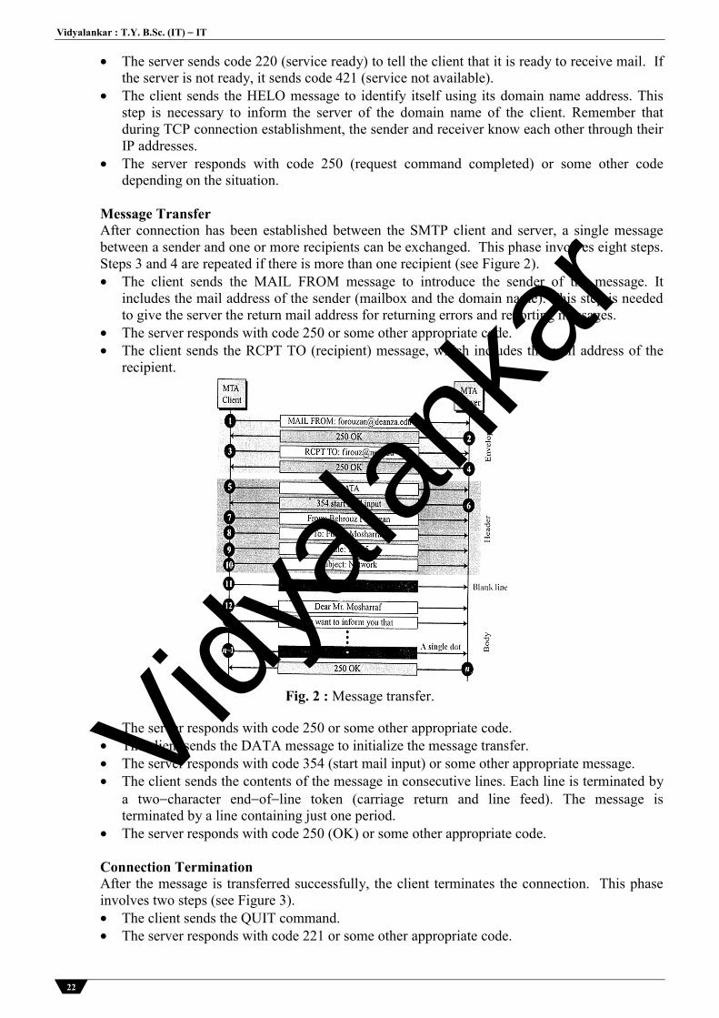
Message Transfer After connection has been established between the SMTP client and server, a single message
between a sender and one or more recipients can be exchanged. This phase involves eight steps. Steps 3 and 4 are repeated if there is more than one recipient (see Figure 2).
The client sends the MAIL FROM message to introduce the sender of the message. It includes the mail address of the sender (mailbox and the domain name). This step is needed to give the server the return mail address for returning errors and reporting messages.
The server responds with code 250 or some other appropriate code. The client sends the RCPT TO (recipient) message, which includes the mail address of the
recipient.
Fig. 2 : Message transfer.
The server responds with code 250 or some other appropriate code. The client sends the DATA message to initialize the message transfer. The server responds with code 354 (start mail input) or some other appropriate message. The client sends the contents of the message in consecutive lines. Each line is terminated by
a twocharacter endofline token (carriage return and line feed). The message is terminated by a line containing just one period.
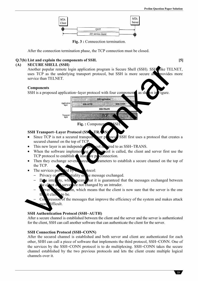
The server responds with code 250 (OK) or some other appropriate code. Connection Termination After the message is transferred successfully, the client terminates the connection. This phase
involves two steps (see Figure 3). The client sends the QUIT command. The server responds with code 221 or some other appropriate code.
Vidyala
nkar
Prelim Question Paper Solution
23
Fig. 3 : Conneection termination.
After the connection termination phase, the TCP connection must be closed. Q.7(b) List and explain the components of SSH. [5](A) SECURE SHELL (SSH) Another popular remote login application program is Secure Shell (SSH). SSH, like TELNET,
uses TCP as the underlying transport protocol, but SSH is more secure and provides more service than TELNET.
Components SSH is a proposed applicationlayer protocol with four components, as shown in Figure.
Fig. : Components of SSH.
SSH TransportLayer Protocol (SSHTRANS) Since TCP is not a secured transport layer protocol, SSH first uses a protocol that creates a
secured channel on the top of TCP. This new layer is an independent protocol referred to as SSHTRANS. When the software implementing this protocol is called, the client and server first use the
TCP protocol to establish an insecure proconnection. Then they exchange several security parameters to establish a secure channel on the top of
the TCP. The services provided by this protocol:
Privacy or confidentiality of the message exchanged. Data integrity, which means that it is guaranteed that the messages exchanged between
the client and server are not changed by an intruder. Server authentication, which means that the client is now sure that the server is the one
that it claims to be. Compression of the messages that improve the efficiency of the system and makes attack
more difficult. SSH Authentication Protocol (SSHAUTH) After a secure channel is established between the client and the server and the server is authenticated
for the client, SSH can call another software that can authenticate the client for the server. SSH Connection Protocol (SSHCONN) After the secured channel is established and both server and client are authenticated for each
other, SHH can call a piece of software that implements the third protocol, SSHCONN. One of the services by the SSHCONN protocol is to do multiplexing. SSHCONN takes the secure channel established by the two previous protocols and lets the client create multiple logical channels over it.
Vidyala
nkar
Vidyalankar : T.Y. B.Sc. (IT) IT
24
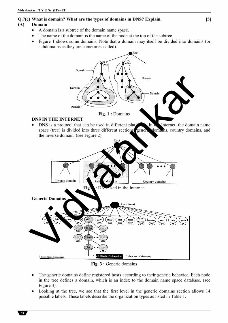
Q.7(c) What is domain? What are the types of domains in DNS? Explain. [5](A) Domain A domain is a subtree of the domain name space. The name of the domain is the name of the node at the top of the subtree. Figure 1 shows some domains. Note that a domain may itself be divided into domains (or
subdomains as they are sometimes called).
Fig. 1 : Domains
DNS IN THE INTERNET DNS is a protocol that can be used in different platforms. In the Internet, the domain name
space (tree) is divided into three different sections: generic domains, country domains, and the inverse domain. (see Figure 2)
Fig. 2 : DNS used in the Internet.
Generic Domains
Fig. 3 : Generic domains
The generic domains define registered hosts according to their generic behavior. Each node
in the tree defines a domain, which is an index to the domain name space database. (see Figure 3).
Looking at the tree, we see that the first level in the generic domains section allows 14 possible labels. These labels describe the organization types as listed in Table 1.
Vidyala
nkar
Prelim Question Paper Solution
25
Table 1 : Generic domain labels. Label Description
aero Airlines and aerospace companies biz Business or firms (similar to "com") com Commercial organizations coop Cooperative business organizations edu Educational institutions gov Government institutions info Information service providers int International organizations mil Military groups museum Museums and other non-profit organizations name Personal names (individuals) net Network support centers org Non-profit organizations pro Professional individual organizations
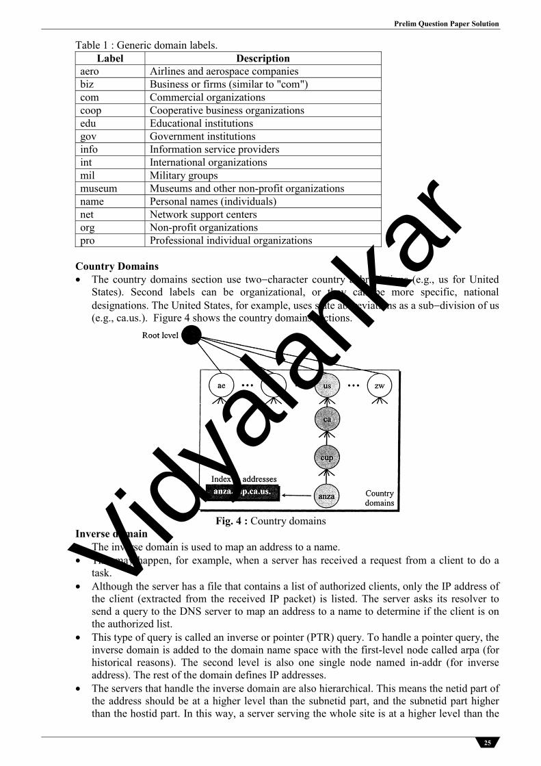
Country Domains The country domains section use twocharacter country abbreviations (e.g., us for United
States). Second labels can be organizational, or they can be more specific, national designations. The United States, for example, uses state abbreviations as a subdivision of us (e.g., ca.us.). Figure 4 shows the country domains sections.
Fig. 4 : Country domains
Inverse domain The inverse domain is used to map an address to a name. This may happen, for example, when a server has received a request from a client to do a
task. Although the server has a file that contains a list of authorized clients, only the IP address of
the client (extracted from the received IP packet) is listed. The server asks its resolver to send a query to the DNS server to map an address to a name to determine if the client is on the authorized list.
This type of query is called an inverse or pointer (PTR) query. To handle a pointer query, the inverse domain is added to the domain name space with the first-level node called arpa (for historical reasons). The second level is also one single node named in-addr (for inverse address). The rest of the domain defines IP addresses.
The servers that handle the inverse domain are also hierarchical. This means the netid part of the address should be at a higher level than the subnetid part, and the subnetid part higher than the hostid part. In this way, a server serving the whole site is at a higher level than the
Vidyala
nkar
Vidyalankar : T.Y. B.Sc. (IT) IT
26
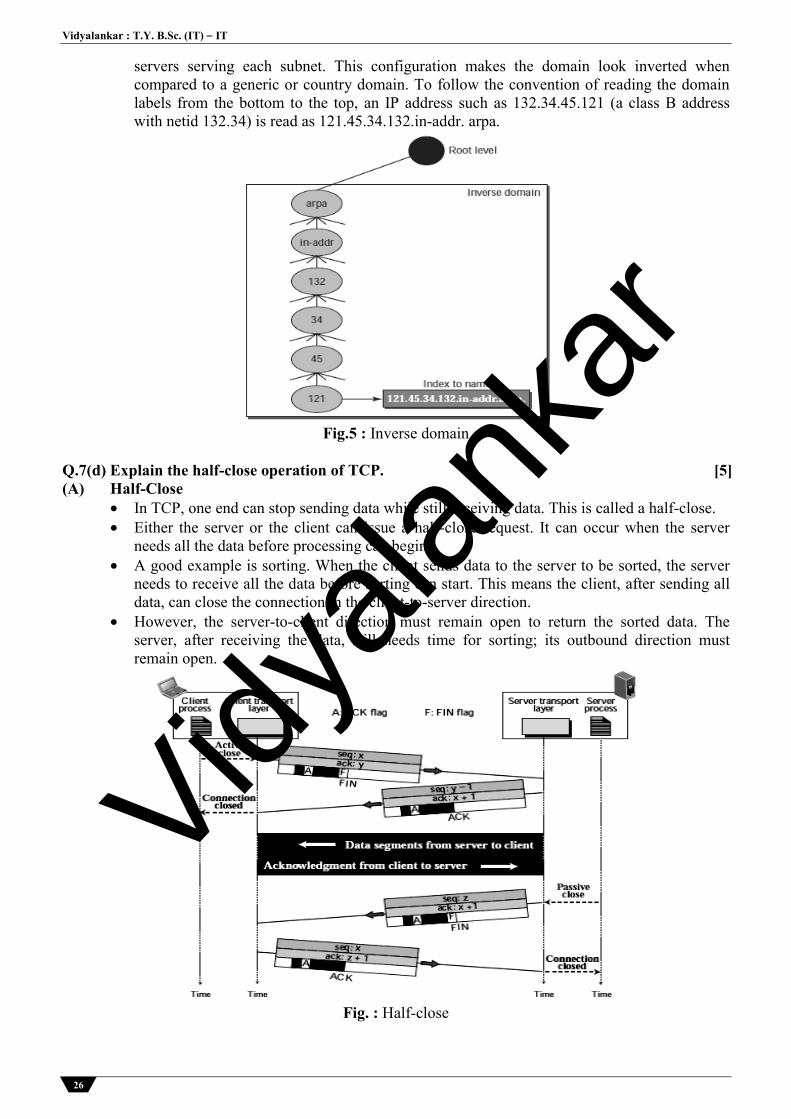
servers serving each subnet. This configuration makes the domain look inverted when compared to a generic or country domain. To follow the convention of reading the domain labels from the bottom to the top, an IP address such as 132.34.45.121 (a class B address with netid 132.34) is read as 121.45.34.132.in-addr. arpa.
Fig.5 : Inverse domain
Q.7(d) Explain the half-close operation of TCP. [5](A) Half-Close In TCP, one end can stop sending data while still receiving data. This is called a half-close. Either the server or the client can issue a half-close request. It can occur when the server
needs all the data before processing can begin. A good example is sorting. When the client sends data to the server to be sorted, the server
needs to receive all the data before sorting can start. This means the client, after sending all data, can close the connection in the client-to-server direction.
However, the server-to-client direction must remain open to return the sorted data. The server, after receiving the data, still needs time for sorting; its outbound direction must remain open.
Fig. : Half-close
Vidyala
nkar

Prelim Question Paper Solution
27
Figure shows an example of a half-close. The data transfer from the client to the server stops. The client half-closes the connection by sending a FIN segment. The server accepts the half-close by sending the ACK segment. The server, however, can still send data. When the server has sent all of the processed data, it sends a FIN segment, which is acknowledged by an ACK from the client.
After half closing the connection, data can travel from the server to the client and acknowledgments can travel from the client to the server. The client cannot send any more data to the server. Note the sequence numbers we have used. The second segment (ACK) consumes no sequence number. Although the client has received sequence number y 1 and is expecting y, the server sequence number is still y 1. When the connection finally closes, the sequence number of the last ACK segment is still x, because no sequence numbers are consumed during data transfer in that direction.
Q.7(e) State and explain the four types of links in OSPF. [5](A) In OSPF terminology, a connection is called a link. Four types of links have been defined: point-
to-point, transient, stub, and virtual (see Figure 1).
Fig. 1 : Types of links
Point-to-Point Link A point-to-point link connects two routers without any other host or router in between. In other words, the purpose of the link (network) is just to connect the two routers. An example of this type of link is two routers connected by a telephone line or a T-line. There is no need to assign a network address to this type of link. Graphically, the routers are represented by nodes, and the link is represented by a bidirectional edge connecting the nodes. The metrics, which are usually the same, are shown at the two ends, one for each direction. In other words, each router has only one neighbor at the other side of the link (see Figure 2).
Fig. 2 : Point-to-point link
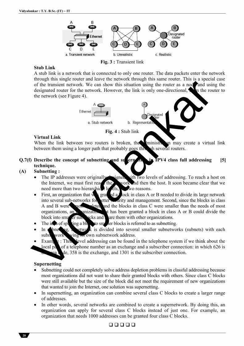
Transient Link A transient link is a network with several routers attached to it. The data can enter through
any of the routers and leave through any router. All LANs and some WANs with two or more routers are of this type. In this case, each router has many neighbors. For example, consider the Ethernet in Figure 3a. Router A has routers B, C, D, and E as neighbors. Router B has routers A, C, D, and E as neighbors. If we want to show the neighborhood relationship in this situation, we have the graph shown in Figure 3b.
This is neither efficient nor realistic. It is not efficient because each router needs to advertise the neighborhood to four other routers, for a total of 20 advertisements. It is not realistic, because there is no single network (link) between each pair of routers; there is only one network that serves as a crossroad between all five routers.
To show that each router is connected to every other router through one single network, the network itself is represented by a node. However, because a network is not a machine, it cannot function as a router. One of the routers in the network takes this responsibility.
It is assigned a dual purpose; it is a true router and a designated router. We can use the topology shown in Figure 3c to show the connections of a transient network.
Vidyala
nkar
Vidyalankar : T.Y. B.Sc. (IT) IT
28
Fig. 3 : Transient link
Stub Link A stub link is a network that is connected to only one router. The data packets enter the network
through this single router and leave the network through this same router. This is a special case of the transient network. We can show this situation using the router as a node and using the designated router for the network. However, the link is only one-directional, from the router to the network (see Figure 4).
Fig. 4 : Stub link
Virtual Link When the link between two routers is broken, the administration may create a virtual link
between them using a longer path that probably goes through several routers. Q.7(f) Describe the concept of subnetting and supernetting in IPV4 class full addressing
technique. [5]
(A) Subnetting : The IP addresses were originally designed with two levels of addressing. To reach a host on
the Internet, we must first reach the network and then the host. It soon became clear that we need more than two hierarchical levels, for two reasons.
First, an organization that was granted a block in class A or B needed to divide its large network into several sub-networks for better security and management. Second, since the blocks in class A and B were almost depleted and the blocks in class C were smaller than the needs of most organizations, an organization that has been granted a block in class A or B could divide the block into smaller subblocks and share them with other organizations.
The idea of splitting a block to smaller blocks is referred to as subnetting. In subnetting, a network is divided into several smaller subnetworks (subnets) with each
subnetwork having its own subnetwork address. Example : Three-level addressing can be found in the telephone system if we think about the
local part of a telephone number as an exchange and a subscriber connection: in which 626 is the area code, 358 is the exchange, and 1301 is the subscriber connection.
Supernetting
Subnetting could not completely solve address depletion problems in classful addressing because most organizations did not want to share their granted blocks with others. Since class C blocks were still available but the size of the block did not meet the requirement of new organizations that wanted to join the Internet, one solution was supernetting.
In supernetting, an organization can combine several class C blocks to create a larger range of addresses.
In other words, several networks are combined to create a supernetwork. By doing this, an organization can apply for several class C blocks instead of just one. For example, an organization that needs 1000 addresses can be granted four class C blocks.
Vidyala
nkar

![T.Y. Diploma : Sem. V [ME/PG/PT] Power Engineering Prelim ...vidyalankar.org/upload/PE_Soln.pdf · Prelim Question Paper Solution [Marks : 100 Q.1(a) (i) ... The MPFI means Multi](https://img.pdfslide.net/doc/110x75/5ab3cd107f8b9a156d8b4d41/ty-diploma-sem-v-mepgpt-power-engineering-prelim-question-paper-solution.jpg)


![Q.1(a) Solve the following : [10] A pictorial view of an ...vidyalankar.org/upload/2_Drg_Soln8416102130373.pdf · Engineering Drawing ... Prelim Question Paper Solution [Marks : 100](https://img.pdfslide.net/doc/110x75/5ab3cdda7f8b9aea528ea27d/q1a-solve-the-following-10-a-pictorial-view-of-an-drawing-prelim.jpg)


![[EJ/ET/EN/EX] Mobile Communication Time : 3 Hrs.] Prelim ...vidyalankar.org/upload/MC_ETRX_Soln.pdf · Prelim Question Paper Solution [Marks : ... and provides higher immunity towards](https://img.pdfslide.net/doc/110x75/5abcd13c7f8b9a8f058e0914/ejetenex-mobile-communication-time-3-hrs-prelim-question-paper-solution.jpg)


![B.E. Sem. VII [EXTC] Fundamentals of Microwave …vidyalankar.org/file/engg_degree/prelim_paper_soln/SemVII/EXTC/... · Fundamentals of Microwave Engineering Prelim Question Paper](https://img.pdfslide.net/doc/110x75/5ab168727f8b9ad9788c3916/be-sem-vii-extc-fundamentals-of-microwave-of-microwave-engineering-prelim.jpg)


![T.E. Sem. V [CMPN] Advanced Database Management …vidyalankar.org/file/engg_degree/prelim_paper_soln/SemV/CMPN/ADBMS.pdfAdvanced Database Management Systems Prelim Question Paper](https://img.pdfslide.net/doc/110x75/5ad9973d7f8b9a86378c2f07/te-sem-v-cmpn-advanced-database-management-database-management-systems.jpg)