Embed Size (px)
Citation preview

Progress In Electromagnetics Research B, Vol. 81, 163–182, 2018
Quad-Band Wearable Slot Antenna with Low SAR Values
for 1.8 GHz DCS, 2.4 GHz WLAN and 3.6/5.5 GHzWiMAX Applications
Danvir Mandal1, * and Shyam S. Pattnaik2
Abstract—In this paper, a quad-band wearable slot antenna with low specific absorption rate (SAR)is presented. By cutting an inverted V-shaped slot with its arms further extended towards the centerof the circular patch, multiple resonant modes of the antenna can be excited to operate on 1.8 GHzDCS, 2.4 GHz WLAN and 3.6/5.5 GHz WiMAX bands. The measured peak gains and impedancebandwidths are about 4.91/7.84/2.58/4.12 dBi and 320/60/80/180 MHz for the 1.8/2.4/3.6/5.5 GHzbands respectively. The SAR of the proposed antenna has been measured using a three layer humantissue model. The estimated SAR values at all the resonant frequencies are well below the thresholdlimit of 2W/kg, which ensures its viability for wearable applications. In order to approximate differentparts of the human body, the SAR values have been estimated for three surface sizes, 120 × 120 mm2,220 × 220 mm2 and 320 × 320 mm2, of the human tissue model, and results are compared. Frequencydetuning of the proposed antenna due to bending along x, y and x-y planes has also been carried out anddiscussed. Further, on arm effect on the antenna performance is investigated, and results are presented.The simulated and measured results are in good agreement, which validates the use of proposed wearableantenna in DCS/WLAN/WiMAX bands.
1. INTRODUCTION
In recent days, due to advent of wearable sensors and body centric communication systems, it is desirableto integrate many wireless communication standards in a single wireless device for personal wirelesscommunication. In order to satisfy these communication standards, wearable multiband antennaswhich can operate at 1.7–1.9 GHz for Digital Cellular System (DCS), 2.4–2.484 GHz/5.15–5.825 GHz forWireless Local Area Network (WLAN) and 3.4–3.69 GHz/5.25–5.85 GHz for Worldwide Interoperabilityfor Microwave Access (WiMAX) are required.
Many multiband slot antennas have been proposed in the past few years [1–7]. In [1], dual bandoperation has been achieved in polygon shaped wearable patch antenna with circular slot and verticalslits on a jeans substrate. Triple band antennas proposed by using U shaped, C and inverted L shapedslots have been reported in [2] and [3]. A triple band switchable antenna with three sickle shaped slotsin ground plane is reported in [4]. Further compact triple band slot antennas with microstrip and squareslots have been presented in [5] and [6]. The Four band characteristics of the slot antenna reported in [7]were generated by etching rectangular slot and inverted T and E shaped stubs. A multiband antennafor LTE/GSM/UMTS and a multi-slot antenna for wireless body arear network have been reportedin [8] and [9].
For wearable antennas, SAR value is a vital parameter. Many human tissue models have been usedin past for the calculation of SAR. Low SAR antennas have been presented in [10–12]. Human body
Received 25 May 2018, Accepted 10 July 2018, Scheduled 19 July 2018* Corresponding author: Danvir Mandal ([email protected]).1 I. K. Gujral Punjab Technical University, Kapurthala, Punjab 144603, India. 2 National Institute of Technical Teachers Trainingand Research, Chandigarh 160026, India.

164 Mandal and Pattnaik
effects on implantable antennas for single equivalent layer and three layer human tissue models havebeen presented in [13]. The electromagnetic energy absorption by homogeneous and layered humantissue models has been analyzed in [14] and [15]. In [16], layered cubic and cylindrical human tissuemodels have been used for SAR calculations. The bending and on arm effect on a wearable antennahas been analyzed in [17] and [18].
A circular patch antenna primarily supports TMz modes where z is perpendicular to the patch. Inorder to find the modes of a circular patch antenna, the circular patch, ground plane, and the substratebetween the two are considered as a circular cavity [19].
In this work, a quad-band wearable slot antenna with a circular patch has been designed on polyestersubstrate [17]. The antenna has low SAR values at all the resonating frequencies, making it viable forwearable applications. Apart from SAR, bending is another major factor that affects the antennaperformance. The effect of bending on frequency detuning of the proposed antenna has also beenmeasured and discussed along x, y and x-y planes. Finally, on arm effect, with and without cloth, havebeen analyzed and results are presented.
The antenna structure and design procedure are explained in Section 2. In Section 3, the results ofthe simulated and handmade antennas are compared and discussed. This section also includes the SARcalculations, effect of bending and on arm performance of the antenna. The conclusions are drawn inSection 4.
2. ANTENNA STRUCTURE AND DESIGN
The basic structure of the proposed quad-band wearable slot antenna is illustrated in Figure 1. Coppertape is used for preparing circular patch and square ground plane.
Figure 1. Quad-band wearable slot antenna.
A polyester cloth substrate with thickness, h = 2.0 mm, dielectric constant, εr = 1.39, and losstangent, tan δ = 0.01 is used to design and fabricate the proposed antenna. The size of the fabricatedantenna considering the ground plane size is 70 × 70 mm2. At first, the radius a of the circular patchis calculated using standard expression given in [19]. The first four modes of circular patch antennaare TMz
110, TMz210, TMz
010, and TMz310. The dominant mode is the TMz
110, whose resonant frequency is
Progress In Electromagnetics Research B, Vol. 81, 2018 165
given by
(fr)110 =1.8412 v0
2πa√
εr
(1)
where v0 is the speed of light in free-space.The radius a of the circular patch is corrected by taking fringing into account and the effective
radius ae is given by
ae = a
{1 +
2hπaεr
[ln
(πa
2h
)+ 1.7726
]}1/2
(2)
Therefore, the resonant frequency for the dominant mode TMz110 is modified using Eq. (2) and given as
(fr)110 =1.8412 v0
2πae√
εr
(3)
Considering resonant frequency, fr = 2.4 GHz for TMz110 mode, a is obtained approximately as 29.01 mm.
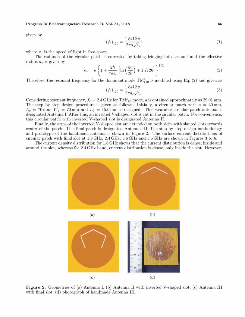
The step by step design procedure is given as follows. Initially, a circular patch with a = 30 mm,Lg = 70 mm, Wg = 70 mm and L3 = 15.0 mm is designed. This wearable circular patch antenna isdesignated Antenna I. After this, an inverted V-shaped slot is cut in the circular patch. For convenience,this circular patch with inverted V-shaped slot is designated Antenna II.
Finally, the arms of the inverted V-shaped slot are extended on both sides with slanted slots towardscenter of the patch. This final patch is designated Antenna III. The step by step design methodologyand prototype of the handmade antenna is shown in Figure 2. The surface current distributions ofcircular patch with final slot at 1.8 GHz, 2.4 GHz, 3.6 GHz and 5.5 GHz are shown in Figures 3 to 6.
The current density distribution for 1.8 GHz shows that the current distribution is dense, inside andaround the slot, whereas for 2.4 GHz band, current distribution is dense, only inside the slot. However,
(a) (b)
(c) (d)
Figure 2. Geometries of (a) Antenna I, (b) Antenna II with inverted V-shaped slot, (c) Antenna IIIwith final slot, (d) photograph of handmade Antenna III.

166 Mandal and Pattnaik
Figure 3. Surface current distribution ofAntenna III at 1.8 GHz.
Figure 4. Surface current distribution ofAntenna III at 2.4 GHz.
Figure 5. Surface current distribution ofAntenna III at 3.6 GHz.
Figure 6. Surface current distribution ofAntenna III at 5.5 GHz.
for 2.4 GHz, the current is flowing all over the circular patch. Similarly, the current distribution for3.6 GHz is dense on the lower left side of the patch. For 5.5 GHz, dense current distribution is observedonly inside the slot and sparse current distribution outside the slot.
The geometrical parameters used to fabricate the wearable quad-band antenna are listed in Table 1.The expressions derived for the estimation of A1, A2, B1 and B2 are given as
A1 =(W 2
1 +(L−L1+u)2)1/2
(4)
A2 =(W 2
2 +(L−L2)2)1/2
(5)
B1 =((W1−W4)
2 + (L1+w)2)1/2
(6)

Progress In Electromagnetics Research B, Vol. 81, 2018 167
B2 =((W2−W3)
2 +(L2+w)2)1/2
(7)
Table 1. Parameters of the proposed low SAR quad-band wearable slot antenna.
Parameters (unit: mm) Antenna II Antenna IIIL 23 23L1 15 15L2 14.5 14.5W1 18 18W2 17 17A1 20.12 20.12A2 19.0 19.0m 0.5 0.5n 1.0 1.0u 1.0 1.0B1 - 18.20B2 - 17.73W3 - 11.5W4 - 10.5v - 1.0w - 2.0
3. RESULTS AND DISCUSSION
The antenna design is simulated using High Frequency Structure Simulator (HFSS). The fabricatedantenna is tested using ANRITSU MS46322A vector network analyzer. The simulated and measuredreflection coefficient (S11) plots are shown in Figure 7 and Figure 8.
The obtained impedance bandwidths are given in Table 2. Antenna I cover two bands from2.33 GHz to 2.44 GHz and 3.95 GHz to 4.01 GHz. Antenna II has four bands that cover from 2.12 GHzto 2.21 GHz, 3.12 GHz to 3.16 GHz, 4.03 GHz to 4.04 GHz and 5.43 GHz to 5.62 GHz. Antenna IIIsatisfies the requirement of DCS, WLAN and WiMAX applications. Antenna III covers four bandsfrom 1.70 GHz to 2.01 GHz, 2.39 GHz to 2.50 GHz, 3.59 GHz to 3.70 GHz and 5.41 GHz to 5.65 GHzwith impedance bandwidths of 310 MHz, 110 MHz, 110 MHz and 240 MHz respectively. The simulatedresonant frequencies of the Antenna III are 1.88 GHz, 2.44 GHz, 3.64 GHz and 5.54 GHz.
Table 2. Simulated and measured impedance bandwidths (%) for the proposed low SAR quad-bandwearable slot antenna.
AntennaBand I (GHz)
/BW (%)Band II (GHz)
/BW (%)Band III (GHz)
/BW (%)Band IV (GHz)
/BW (%)Antenna I 2.33–2.44/4.6 3.95–4.01/1.5 - -Antenna II 2.12–2.21/4.2 3.12–3.16/1.3 4.03–4.04/0.2 5.43–5.62/3.4
Antenna III 1.70–2.01/16.7 2.39–2.50/4.5 3.59–3.70/3.0 5.41–5.65/4.3Antenna III(Measured)
1.64–1.96/17.7 2.37–2.43/2.5 3.55–3.63/2.2 5.39–5.57/3.3

168 Mandal and Pattnaik
Figure 7. Simulated reflection coefficient (S11) of Antenna I, Antenna II and Antenna III.
Figure 8. Simulated and measured reflection coefficient (S11) of Antenna III.
The measured operating bands of Antenna III range in 1.64–1.96 GHz, 2.37–2.43 GHz, 3.55–3.63 GHz and 5.39–5.57 GHz with the impedance bandwidth of 320 MHz, 60 MHz, 80 MHz and 180 MHzrespectively. The measured resonant frequencies of the Antenna III are 1.88 MHz, 2.4 GHz, 3.6 GHz and5.48 GHz.
The simulated and measured radiation patterns at center frequencies of the four bands, i.e., 1.8 GHz,2.4 GHz, 3.6 GHz and 5.5 GHz, can be observed in Figure 9 to Figure 12. Figure 13 shows the measuredpeak gain of the proposed handmade Antenna III. The Inset in Figure 13 shows the photograph of thequad band wearable antenna in anechoic chamber during gain and radiation pattern measurement.
The gain of the proposed antenna is measured using the following expression:Gain of the Test Antenna = G + (PT − PR) (8)

Progress In Electromagnetics Research B, Vol. 81, 2018 169
(a) (b)
(c) (d)
Figure 9. (a) 3-D simulated radiation pattern at 1.8 GHz, 2-D simulated and measured radiationpatterns at 1.8 GHz, (b) X-Z plane, (c) Y -Z plane, (d) X-Y plane.
Table 3. Material parameters of human tissue layers.
Tissue Layer Frequency (GHz) Permittivity (εr) Conductivity σ (S/m)
Skin
1.8 38.87 1.1842.4 38.06 1.4403.6 36.92 2.0855.5 35.36 3.463
Fat
1.8 5.349 0.0782.4 5.285 0.1023.6 5.164 0.1605.5 4.982 0.273
Muscle
1.8 54.44 1.3892.4 53.63 1.7743.6 52.05 2.7685.5 49.42 4.832
where G is the gain of the reference pyramidal horn antenna known over anisotropic antenna, PT thepower received by test antenna, and PR the power received by reference antenna. The measured peakgain of the proposed antenna at 1.8 GHz, 2.4 GHz, 3.6 GHz and 5.5 GHz is 4.91 dBi, 7.84 dBi, 2.58 dBiand 4.12 dBi respectively.

170 Mandal and Pattnaik
3.1. SAR Calculations
The proposed antenna is simulated in the vicinity of a three layer human tissue model, as shown inFigure 14. The thickness of the three human tissue layers used, i.e., skin, fat and muscle, are 3 mm,13 mm and 60 mm. The gap between the antenna and skin layer is 5mm. The values of the permittivity(εr) and conductivity (σ) of the skin, fat and muscle are obtained from [20]. The loss tangent anddensity of the layers are kept same as of [1] and [15]. The material properties of human tissue layersused for SAR calculation are given in Table 3.
Initially, the surface size of 120 × 120 mm2 is considered for human tissue model. Further, toapproximate different parts of the human body, the averaged SAR values are estimated for threeascending surface sizes of the human tissue model, i.e., 120×120 mm2, 220×220 mm2 and 320×320 mm2.The local SAR distributions at 1.8 GHz, 2.4 GHz, 3.6 GHz and 5.5 GHz, on the surface of the skin layer
(a)(a) (b)
(c) (d)
Figure 10. (a) 3-D simulated radiation pattern at 2.4 GHz, 2-D simulated and measured radiationpatterns at 2.4 GHz, (b) X-Z plane, (c) Y -Z plane, (d) X-Y plane.
Table 4. Estimated SAR values for ascending surface sizes of the human tissue model.
Surface size (mm2)of the human tissue model
Average SAR (W/kg)1.8 GHz 2.4 GHz 3.6 GHz 5.5 GHz
120 × 120 0.121 0.411 0.874 0.954220 × 220 0.048 0.394 0.791 0.881320 × 320 0.019 0.358 0.566 0.798

Progress In Electromagnetics Research B, Vol. 81, 2018 171
(a) (b)
(c) (d)
Figure 11. (a) 3-D simulated radiation pattern at 3.6 GHz, 2-D simulated and measured radiationpatterns at 3.6 GHz, (b) X-Z plane, (c) Y -Z plane, (d) X-Y plane.
with 120×120 mm2 surface size, are shown in Figures 15 to 18. The estimated SAR values of the proposedantenna for all resonant frequencies and surface sizes are summarized in Table 4. The simulations forSAR estimation are done in HFSS. The input power of 0.5 W is given to the antenna during SARsimulation. The averaged SAR is calculated using IEEE C95.3 standard, in which SAR is averaged over10 g of biological tissue.
The maximum local SAR found in the skin layer of human tissue model at 1.8 GHz, 2.4 GHz, 3.6 GHzand 5.5 GHz is 0.274 W/kg, 1.065 W/kg, 2.137 W/kg and 2.374 W/kg respectively. The calculatedaveraged SAR values in human tissue model with 120 × 120 mm2 surface size at 1.8 GHz, 2.4 GHz,3.6 GHz and 5.5 GHz are 0.121 W/kg, 0.411 W/kg, 0.874 W/kg and 0.954 W/kg.
Similarly, the estimated averaged SAR values for 220 × 220 mm2 and 320 × 320 mm2 surfacesizes at 1.8/2.4/3.6/5.5 GHz are 0.048/0.394/0.791/0.881 W/kg and 0.019/0.358/0.566/0.798 W/kg,respectively. It is observed that, with the increase in the surface size of the human tissue model,the averaged SAR values tend to decrease. The simulated radiation efficiency and maximum gain of thequad band wearable antenna in free space and over human tissue model (120× 120 mm2) are calculatedand compared in Table 5. The simulated radiation efficiency of the proposed antenna at 1.8 GHz,2.4 GHz, 3.6 GHz and 5.5 GHz in free space and over human tissue model is 92.45/75.22/63.26/88.95%and 85.11/68.07/44.29/77.65%, respectively.
The simulated maximum gain of the quad-band antenna in free space and over human tissue modelat 1.8 GHz, 2.4 GHz, 3.6 GHz and 5.5 GHz is 14.21/6.67/4.91/6.70 dB and 13.10/6.63/3.76/6.11 dBrespectively.
Figures 19 to 22, compare the simulated radiation patterns of the proposed antenna in free spacewith simulated radiation patterns over numerical human tissue model (120× 120 mm2). The simulatedradiation patterns of the proposed antenna in free space and over human tissue model are quite different

172 Mandal and Pattnaik
(a) (b)
(c) (d)
Figure 12. (a) 3-D simulated radiation pattern at 5.5 GHz, 2-D simulated and measured radiationpatterns at 5.5 GHz, (b) X-Z plane, (c) Y -Z plane, (d) X-Y plane.
Figure 13. Measured peak gain of the proposed Antenna III.

Progress In Electromagnetics Research B, Vol. 81, 2018 173
(a) (b)
Figure 14. (a) Modelling of Antenna III on three layer human tissue for SAR estimation at 1.8 GHz,2.4 GHz, 3.6 GHz and 5.5 GHz, (b) photograph of the proposed antenna over three layer human tissuemodel in HFSS.
Figure 15. Local SAR distribution on the surface of skin layer at 1.8 GHz.
Table 5. Radiation efficiency and maximum gain in free space and over human tissue model.
ResonatingFrequency
Radiation Efficiency (%) Maximum Gain (dB)
In free spaceOver humantissue model
In free spaceOver humantissue model
1.8 GHz 92.45 85.11 14.21 13.102.4 GHz 75.22 68.07 6.67 6.633.6 GHz 63.26 44.29 4.91 3.765.5 GHz 88.95 77.65 6.70 6.11

174 Mandal and Pattnaik
Figure 16. Local SAR distribution on the surface of skin layer at 2.4 GHz.
Figure 17. Local SAR distribution on the surface of skin layer at 3.6 GHz.
in X-Z and Y -Z planes, but in X-Y plane, the radiations patterns are almost similar at all the resonantfrequencies.
3.2. Effect of Bending on Antenna Performance
The effect of bending is measured in x-plane, y-plane and x-y plane. The handmade prototype ofAntenna III is bent by keeping it around a PVC (poly vinyl chloride) pipe as shown in Figure 23.The diameter of the PVC pipe is 150 mm. Figure 24 shows the measured reflection coefficient (S11)of Antenna III under three bending conditions. The results show that lower frequency bands (1.8 GHzand 2.4 GHz) shifts to the left side of the spectrum with further decrease in reflection coefficient, whenbent along x and y planes.
On the contrary, the higher frequency bands (3.6 GHz and 5.5 GHz) shift to the right side ofthe spectrum with decrease in reflection coefficient, when being bent along x and y planes. In x-

Progress In Electromagnetics Research B, Vol. 81, 2018 175
Figure 18. Local SAR distribution on the surface of skin layer at 5.5 GHz.
(a) (b)
(c)
Figure 19. Comparison of 2-D simulated radiation patterns in free space and over human tissue modelat 1.8 GHz. (a) X-Z plane, (b) Y -Z plane, (c) X-Y plane.
y plane bending, the lower bands and upper bands shift has landed approximately in between thelower bands and upper bands of x-plane and y-plane bending. Frequency detuning, which is observedwhen measurements are compared for all the three cases of bending is presented in Table 6. Maximumfrequency detuning is observed for 1.8 GHz band when antenna is bent along x-plane, where as minimumfrequency detuning is observed for 3.6 GHz band when antenna is bent along y-plane.

176 Mandal and Pattnaik
(a) (b)
(c)
Figure 20. Comparison of 2-D simulated radiation patterns in free space and over human tissue modelat 2.4 GHz. (a) X-Z plane, (b) Y -Z plane, (c) X-Y plane.
Table 6. Frequency detuning for bending in x, y and x-y plane.
Bending CaseFrequency detuning (%)
1.8 GHz Band 2.4 GHz Band 3.6 GHz Band 5.5 GHz Bandx-plane 7.45 6.67 3.34 4.01y-plane 2.13 1.67 1.12 1.45
x-y plane 5.32 5.0 2.22 3.29
3.3. On Arm Effect on Antenna Performance
The on arm effect on antenna performance has also been analyzed. Four cases of the proposed antenna,on arm, are considered as shown in Figure 25. Two cases are x-plane and y-plane perpendicular to armlength, without cloth, and two cases are x-plane and y-plane perpendicular to arm length, with cloth.
Measured reflection coefficient of antenna on different arm conditions is shown in Figure 26.Frequency detuning, which is observed when measurements are compared for all the four cases ofon arm performance are presented in Table 7. The 1.8 GHz band shifts to the left side of the spectrumfor all four cases of on arm performance.
The 2.4 GHz band shifts to the left side for Case 1, does not shift for Case 2, and shifts to the rightside of the spectrum for Cases 3 and 4 of on arm condition.
The 3.6 GHz band shifts to the left side for Case 1, shifts to the right side for Case 2, and shifts tothe right side for Cases 3 and 4, respectively. The last 5.5 GHz band shifts to the left side for Cases 1and 2, whereas it shifts to the right side of the spectrum for Cases 3 and 4. The maximum frequencydetuning during on arm measurements is calculated at 1.8 GHz band for Cases 1 and 2. For 2.4 GHz

Progress In Electromagnetics Research B, Vol. 81, 2018 177
(a) (b)
(c)
Figure 21. Comparison of 2-D simulated radiation patterns in free space and over human tissue modelat 3.6 GHz. (a) X-Z plane, (b) Y -Z plane, (c) X-Y plane.
(a) (b)
(c)
Figure 22. Comparison of 2-D simulated radiation patterns in free space and over human tissue modelat 5.5 GHz. (a) X-Z plane, (b) Y -Z plane, (c) X-Y plane.

178 Mandal and Pattnaik
(a) (b) (c)
Figure 23. Photographs of quad-band wearable slot antenna under three bending conditions. (a) Bentalong x-plane, (b) bent along y-plane, (c) diagonally bent along x-y plane.
Figure 24. Reflection coefficient (S11) characteristics of the quad-band wearable slot antenna underdifferent bending conditions.
Table 7. Frequency detuning for different on arm conditions.
Case On arm conditionFrequency detuning (%)
1.8 GHz 2.4 GHz 3.6 GHz 5.5 GHzBand Band Band Band
Case 1x-plane perpendicular
to arm length (w/o cloth)9.58 1.67 1.11 1.09
Case 2y-plane perpendicular
to arm length (w/o cloth)9.58 0.0 1.11 1.09
Case 3x-plane perpendicular
to arm length (with cloth)2.13 4.17 5.0 1.46
Case 4y-plane perpendicular
to arm length (with cloth)2.13 5.83 2.78 1.46

Progress In Electromagnetics Research B, Vol. 81, 2018 179
band, no shift in the frequency is observed for Case 2. Minimum frequency detuning has been foundfor Cases 1 and 2 at 5.5 GHz band.
Table 8 illustrates the comparison between the proposed antenna and the antennas described inthe references. It can be seen that the dual band antenna in [1] has the smallest SAR value at 1.8 GHz,but its size is larger than that of our proposed antenna. The table reveals that the SAR values ofthe proposed antenna at all the resonant frequencies are lower than that of the other works listed inTable 8. The gain and radiation efficiency of the proposed antenna is better than almost all antennasproposed in references listed in Table 8. The antenna parameters which were not provided in referencesare marked with “x” in Table 8.
Table 8. Comparison of the proposed antenna with other published works.
Ref.Size
(mm)
ResonantFrequency
(GHz)
Bandwidth(MHz/%)
Gain(dBi)
RadiationEfficiency
(%)
SAR(W/kg)
[1]240×240×1
0.91.8
xx
8.17.4
20.5010.30
0.00110.0034
[8]55
×110×5
0.79–0.961.70–2.73
1691030
−0.91–0.251.40–5.48
24–4440–78
0.44(0.84 GHz)
0.64(0.935 GHz)
1.51(1.85 GHz)
0.99(2.45 GHz)
[9]68.10×41.98×4.445
3.54.55.5
56.9 %xxx
476251
4.504.106.06
[10]81×81×4
2.45 360 7.3 70 0.23
[11]40×80×12
0.91.8
2292
0.911.76
78.5894.35
0.670.58
[12]78×40×0.8
0.91.81.92.1
230.4(0.725–0.95 GHz)
522.24(1.74–2.25 GHz)
2.02.142.512.58
98899498
1.501.801.531.15
[14]32×29×1.5
3.06.08.0
xxx
xxx
xxx
16.68.007.20
ProposedAntenna
70×70×2
1.82.43.65.5
3206080180
4.917.842.584.12
92.4575.2263.2688.95
0.0190.3580.5660.798

180 Mandal and Pattnaik
(a) (b)
(c) (d)
Figure 25. Photographs of quad-band wearable slot antenna on different arm conditions. (a) x-planeperpendicular to arm length (without cloth), (b) y-plane perpendicular to arm length (without cloth),(c) x-plane perpendicular to arm length (with cloth), (d) y-plane perpendicular to arm length (withcloth).
Figure 26. Reflection coefficient (S11) characteristics of the quad-band wearable slot antenna ondifferent arm conditions.

Progress In Electromagnetics Research B, Vol. 81, 2018 181
4. CONCLUSION
This paper presents a handmade low SAR quad-band wearable slot antenna and its design procedure,which is based on simple slot antenna design concepts. The antenna has shown appreciable gain andsmooth radiation pattern characteristics over 1.8 GHz DCS, 2.4 GHz WLAN and 3.6/5.5 GHz WiMAXbands. The estimated SAR values at all the resonant frequencies lie well below the threshold limitof 2 W/kg, ensuring the feasibility of the proposed antenna for wearable applications. The resultsshow that surface size of the human tissue model has significant effect on SAR calculations. With theincrease in the surface size of the three layer human tissue model, the SAR values tend to decrease. Thisinvestigation offers selection criteria to choose the body part of the human body for antenna placementduring SAR calculations. The effect of bending along x, y and x-y planes has also been investigated, andfrequency detuning is presented and discussed. Finally, on arm performances of the proposed antenna,with cloth and without cloth, have been measured and discussed.
ACKNOWLEDGMENT
We acknowledge I. K. Gujral Punjab Technical University, Kapurthala, Punjab, India for providing theopportunity to do research and publish results.
REFERENCES
1. Sundarsingh, E. F., S. Velan, M. Kanagasabai, A. K. Sarma, C. Raviteja, and M. G. N. Alsath,“Polygon-shaped slotted dual-band antenna for wearable applications,” IEEE Antennas andWireless Propagation Letters, Vol. 13, 611–614, 2014.
2. Lee, K. F., S. L. S. Yang, and A. A. Kishk, “Dual- and multiband U-slot patch antennas,” IEEEAntennas and Wireless Propagation Letters, Vol. 7, 645–647, 2008.
3. Lu, J. H. and B. J. Huang, “Planar compact slot antenna with multi-band operation for IEEE802.16m application,” IEEE Transactions on Antennas and Propagation, Vol. 61, No. 3, 1411–1414, Mar. 2013.
4. Saghati, A. P., M. Azarmanesh, and R. Zaker, “A novel switchable single- and multifrequencytriple-slot antenna for 2.4-GHz bluetooth, 3.5-GHz WiMax, and 5.8-GHz WLAN,” IEEE Antennasand Wireless Propagation Letters, Vol. 9, 534–537, 2010.
5. Dang, L., Z. Y. Lei, Y. J. Xie, G. L. Ning, and J. Fan, “A compact microstrip slot triple-bandantenna for WLAN/WiMAX applications,” IEEE Antennas and Wireless Propagation Letters,Vol. 9, 1178–1181, 2010.
6. Hu, W., Y. Z. Yin, P. Fei, and X. Yang, “Compact triband square-slot antenna with symmetricalL-strips for WLAN/WiMAX applications,” IEEE Antennas and Wireless Propagation Letters,Vol. 10, 462–465, 2011.
7. Cao, Y. F., S. W. Cheung, and T. I. Yuk, “A multi-band slot antenna for GPS/WiMAX/WLANsystems,” IEEE Transactions on Antennas and Propagation, Vol. 63, No. 3, 952–958, Mar. 2015.
8. Hong, Y., J. Tak, J. Baek, B. Myeong, and J. Choi, “Design of a multiband antenna forLTE/GSM/UMTS band operation,” International Journal of Antennas and Propagation, Vol. 2014,Article ID 548160, 9 pages, 2014.
9. Wei, Y. F. and C. Roblin, “Multislot antenna with a screening backplane for UWB WBANapplications,” International Journal of Antennas and Propagation, Vol. 2012, Article ID 731912,12 pages, 2012.
10. Gao, G. P., B. Hu, S. F. Wang, and C. Yang, “Wearable circular ring slot antenna with EBGstructure for wireless body area network,” IEEE Antennas and Wireless Propagation Letters,Vol. 17, 434–437, 2018.
11. Kusuma, A. H., A. F. Sheta, I. Elshafiey, Z. Siddiqui, M. A. Alkanhal, S. Aldosari, andS. A. Alshebeili, “A new low SAR antenna structure for wireless handset applications,” ProgressIn Electromagnetic Research, Vol. 112, 23–40, 2011.

182 Mandal and Pattnaik
12. Faruque, M. R. I., M. I. Hossain, and M. T. Islam, “Low specific absorption rate microstrip patchantenna for cellular phone applications,” IET Microwaves, Antennas & Propagation, Vol. 9, No. 14,1540–1546, 2015.
13. Gemio, J., J. Parron, and J. Soler, “Human body effects on implantable antennas for ISMbands applications: Models comparison and propagation losses study,” Progress In ElectromagneticResearch, Vol. 110, 437–452, 2010.
14. Klemm, M. and G. Troester, “EM energy absorption in the human body tissues due to UWBantennas,” Progress In Electromagnetic Research, Vol. 62, 261–280, 2006.
15. Kivekas, O., T. Lehtiniemi, and P. Vainikainen, “On the general energy absorption mechanism inthehuman tissue,” Microwave and Optical Technology Letters, Vol. 43, No. 3, 195–201, Nov. 2004.
16. Yan, S. and G. A. E. Vandenbosch, “Radiation pattern reconfigurable wearable antenna based onmetamaterial structure,” IEEE Antennas and Wireless Propagation Letters, Vol. 15, 1715–1718,2016.
17. Joshi, J. G., S. S. Pattnaik, and S. Devi, “Metamaterial embedded wearable rectangular microstrippatch antenna,” International Journal of Antennas and Propagation, Vol. 2012, Article ID 974315,9 pages, 2012.
18. Hu, B., G. P. Gao, L. L. He, X. D. Cong, and J. N. Zhao, “Bending and on-arm effects on awearable antenna for 2.45 GHz body area network,” IEEE Antennas and Wireless PropagationLetters, Vol. 15, 378–381, 2016.
19. Balanis, C. A., Antenna Theory: Analysis and Design, 3rd Edition, John Wiley & Sons, 2005.20. FCC: Body tissue dielectric parameters, http://www.fcc.gov/oet/rfsafety/dielectric.html.


![Compact Mobile Quad-Band Slot Antenna Design for GPS L1, WiMAX…arizona.openrepository.com/arizona/bitstream/10150/... · · 2017-11-18In other research, parasitic patches [6],](https://img.pdfslide.net/doc/110x75/5ab01c017f8b9adb688e7e40/compact-mobile-quad-band-slot-antenna-design-for-gps-l1-wimax-other-research.jpg)