Embed Size (px)
Citation preview

1
By:
Serial #:
Operations Manual
Portico 5024Quad Microphone Amplifier

1. Read these instructions. 2. Keep these instructions.3. Heed all warnings.4. Follow all instructions.5. Do not use this apparatus near water.6. Clean only with a dry cloth.7. Do not block any ventilation openings. Install in accordance with the
manufacturer’s instructions.8. Do not install near any heat sources such as radiators, heat registers,
stoves, or other apparatus (including amplifiers) that produce heat.9. Do not defeat the safety purpose of the polarized or grounding-type
plug. A polarized plug has two blades with one wider than the other. A grounding-type plug has two blades and a third grounding prong. The wide blade or the third prong are provided for your safety. If the provided plug does not fit into your outlet, consult an electrician for replacement of the obsolete outlet.
10. Protect the power cord from being walked on or pinched particularly at plugs, convenience receptacles, and the point where they exit from the apparatus.
11. Only use attachments/accessories specified by the manufacturer.12. Use only with a cart, stand, tripod, bracket, or
table specified by the manufacturer, or sold with the apparatus. When a cart is used, use caution when moving the cart/apparatus combination to avoid injury from tip-over.
13. Unplug this apparatus during lightning storms or when unused for long periods of time.
14. Refer all servicing to qualified service personnel. Servicing is required when the apparatus has been damaged in any way, such as power-supply cord or plug is damaged, liquid has been spilled or objects have fallen into the apparatus, the apparatus has been exposed to rain or moisture, does not operate normally, or has been dropped.
15. This apparatus shall not be exposed to dripping or splashing, and no object filled with liquids, such as vases or beer glasses, shall be placed on the apparatus.
16. Do not overload wall outlets and extension cords as this can result in a risk of fire or electric shock.
17. This apparatus has been designed with Class-I construction and must be connected to a mains socket outlet with a protective earthing connection (the third grounding prong).
18. This apparatus has been equipped with a rocker-style AC mains power switch. This switch is located on the rear panel and should remain readily accessible to the user.
19. The MAINS plug or an appliance coupler is used as the disconnect device, so the disconnect device shall remain readily operable.
20. NOTE: This equipment has been tested and found to comply with the limits for a Class B digital device, pursuant to part 15 of the FCC Rules. These limits are designed to provide reasonable protection against harmful interference in a residential installation. This equipment generates, uses, and can radiate radio frequency energy and, if not installed and used in accordance with the instructions, may cause harmful interference to radio communications. However, there is no guarantee that interference will not occur in a particular installation.
If this equipment does cause harmful interference to radio or television reception, which can be determined by turning the equipment o� and on, the user is encouraged to try to correct the interference by one or more of the following measures:
• Reorient or relocate the receiving antenna.• Increase the separation between the equipment and the
receiver.• Connect the equipment into an outlet on a circuit different from
that to which the receiver is connected.• Consult the dealer or an experienced radio/TV technician for
help. CAUTION: Changes or modifications to this device not expressly
approved by Rupert Neve Designs LLC, could void the user's authority to operate the equipment under FCC rules.
21. This apparatus does not exceed the Class A/Class B (whichever is applicable) limits for radio noise emissions from digital apparatus as set out in the radio interference regulations of the Canadian Department of Communications.
ATTENTION — Le présent appareil numérique n’émet pas de bruits radioélectriques dépassant las limites applicables aux appareils numériques de class A/de class B (selon le cas) prescrites dans le réglement sur le brouillage radioélectrique édicté par les ministere des communications du Canada.
22. Exposure to extremely high noise levels may cause permanent hearing loss. Individuals vary considerably in susceptibility to noise-induced hearing loss, but nearly everyone will lose some hearing if exposed to sufficiently intense noise for a period of time. The U.S. Government’s Occupational Safety and Health Administration (OSHA) has specified the permissible noise level exposures shown in the following chart.
According to OSHA, any exposure in excess of these permissible limits could result in some hearing loss. To ensure against potentially dangerous exposure to high sound pressure levels, it is recommended that all persons exposed to equipment capable of producing high sound pressure levels use hearing protectors while the equipment is in operation. Ear plugs or protectors in the ear canals or over the ears must be worn when operating the equipment in order to prevent permanent hearing loss if exposure is in excess of the limits set forth here:
Important Safety Instructions
CAUTION AVISRISK OF ELECTRIC SHOCK. DO NOT OPEN
RISQUE DE CHOC ELECTRIQUE. NE PAS OUVRIR
CAUTION: TO REDUCE THE RISK OF ELECTRIC SHOCK DO NOT REMOVE COVER (OR BACK)NO USER-SERVICEABLE PARTS INSIDE. REFER SERVICING TO QUALIFIED PERSONNEL
ATTENTION: POUR EVITER LES RISQUES DE CHOC ELECTRIQUE, NE PAS ENLEVER LE COUVERCLE. AUCUN ENTRETIEN DE PIECES INTERIEURES PAR L'USAGER.
CONFIER L'ENTRETIEN AU PERSONNEL QUALIFIE.AVIS: POUR EVITER LES RISQUES D'INCENDIE OU D'ELECTROCUTION, N'EXPOSEZ PAS CET ARTICLE
A LA PLUIE OU A L'HUMIDITE
The lightning flash with arrowhead symbol within an equilateral triangle is intended to alert the user to the presence of uninsulated "dangerous voltage" within the product's enclosure, that may be of sufficient magnitude to constitute a risk of electric shock to persons.Le symbole éclair avec point de flèche à l'intérieur d'un triangle équilatéral est utilisé pour alerter l'utilisateur de la présence à l'intérieur du coffret de "voltage dangereux" non isolé d'ampleur suffisante pour constituer un risque d'éléctrocution.
The exclamation point within an equilateral triangle is intended to alert the user of the presence of important operating and maintenance (servicing) instructions in the literature accompanying the appliance.Le point d'exclamation à l'intérieur d'un triangle équilatéral est employé pour alerter les utilisateurs de la présence d'instructions importantes pour le fonctionnement et l'entretien (service) dans le livret d'instruction accompagnant l'appareil. WARNING — To reduce the risk of fire or electric shock, do not
expose this apparatus to rain or moisture.
Duration, per day in hours
Sound Level dBA, Slow Response
Typical Example
8 90 Duo in small club6 924 95 Subway Train3 972 100 Typical music via head phones 1.5 1021 105 Siren at 10 m distance 0.5 1100.25 or less 115 Loudest parts at a rock concert
PORTABLE CARTWARNING
2
Portico 5024: Quad Microphone Amplifier
Thank you for your purchase of the 5024 Quad Mic Amp. Everyone at Rupert Neve Designs hope you enjoy using this tool as much as we have enjoyed designing and building it. Please take note of the fol-lowing list of safety concerns and power requirements before the use of this or any Portico Series product. Safety It’s usual to provide a list of “do’s and don’ts” under this heading but mostly these amount to common sense issues. However here are some reminders:
The Portico 5024 dissipates about 15 watts, which means that it will get warm in use. The heat generated is radiated through the case work. To avoid overheating Portico™ modules should not be stacked imme-diately above or adjacent to other equipment that gets hot. Also bear in mind that other equipment may radiate strong hum fields which could spoil the performance of your Portico module.
Don’t operate your Portico™ module in or around water! Electronic equipment and liquids are not good friends. If any liquid is spilled such as soda, coffee, alcoholic or other drink, the sugars and acids will have a very detrimental effect. Sugar crystals act like little rectifiers and can produce noise (crackles, etc.). SWITCH OFF IMMEDIATELY because once current starts to flow, the mixture hardens, can get very hot (burnt toffee!) and cause permanent and costly damage. Please contact support as soon as possible at [email protected] for resolution.
Don’t be tempted to operate a Portico module with the cover removed. The cover provides magnetic screening from hum and R.F. stray fields.
Power RequirementsEach 5024 unit has a high quality, low noise switching power supply that is further filtered and shunt regulated for an exceptionally quiet and reliable power source for the audio circuits. The power sup-ply is considered “universal” in the sense that it will accept 100V through 240V AC and complies with standard mains voltages around the world. Be absolutely sure to disconnect mains power (remove the power cable from the IEC power connector at the back panel) before checking the fuse. The fuse is located in the IEC power input connector and is accessed by opening the small panel labeled “FUSE”. The fuse should always be replaced with the correct value and type. The 5024’s power supply requires a 5x20 mm 2.5 amp fast acting ceramic body fuse Bussman type GDA 2.5A or equivalent.
3
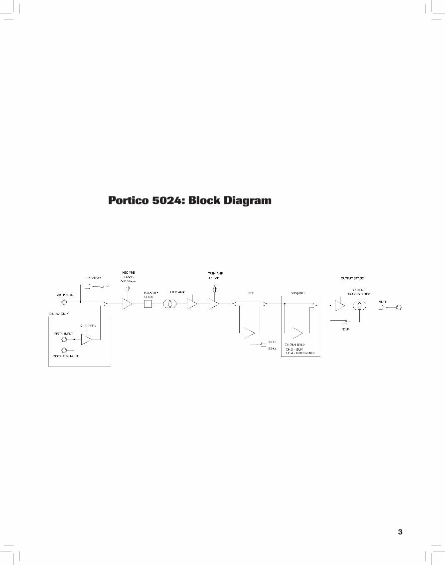
Portico 5024: Block Diagram
4
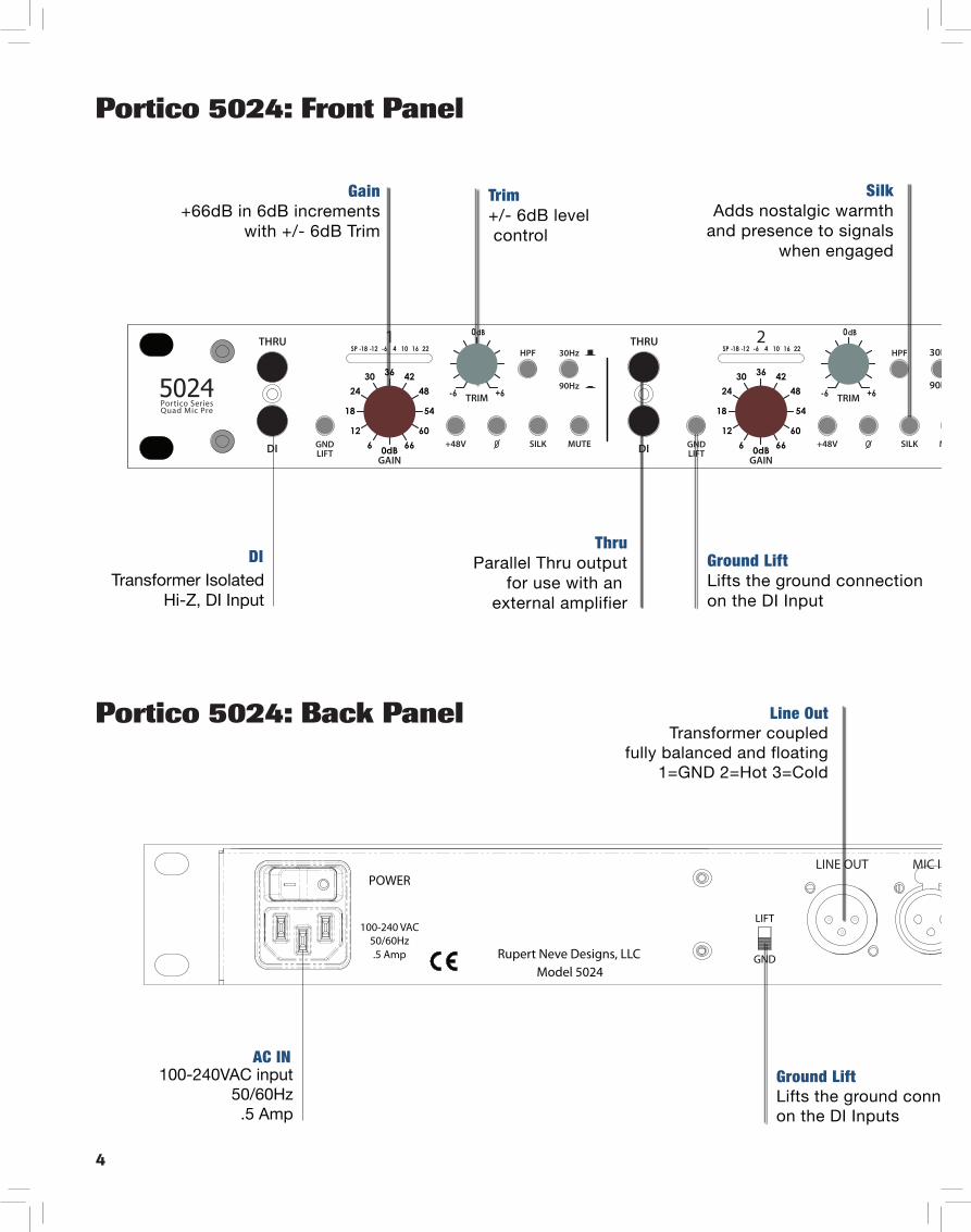
Portico 5024: Front Panel
Portico 5024: Back Panel
AC IN
Mic Input
100-240VAC input50/60Hz.5 Amp
Line OutTransformer coupled
fully balanced and floating1=GND 2=Hot 3=Cold
Ground LiftLifts the ground connectionon the DI Inputs
3MIC IN MIC INLINE OUTMIC INLINE OUTLINE OUTMIC INLINE OUT
124
GND
LIFT100-240 VAC
50/60Hz
POWER
Rupert Neve Designs, LLCModel 5024
.5 Amp
TLA & Transformer Balanced, 10K Ohm 1=GND 2=Hot 3=Cold
M/SPolarityDI
HPS Frequency
Mute
HPFEngages the HPF circuitry
Selects between 30Hz and 90Hz for the HPF
Transformer Isolated Hi-Z, DI Input
Changes CH 3 & 4 from independent to Mid (CH 3) and Side (CH 4)
Mutes the output signal
Reverses the polarity of the
SilkAdds nostalgic warmthand presence to signals
when engaged
Ground LiftLifts the ground connectionon the DI Input
ThruParallel Thru output
for use with an external amplifier
Gain+66dB in 6dB increments
with +/- 6dB Trim
Trim+/- 6dB level control
LED Meters8 Point LEDPeak Meters
source material
Rupert Neve Designs
3630
24
18
12
6 0dB 66
60
54
48
42 3630
24
18
12
6 0dB 66
60
54
48
423630
24
18
12
6 0dB 66
60
54
48
423630
24
18
12
6 0dB 66
60
54
48
42

5
AC IN
Mic Input
100-240VAC input50/60Hz.5 Amp
Line OutTransformer coupled
fully balanced and floating1=GND 2=Hot 3=Cold
Ground LiftLifts the ground connectionon the DI Inputs
3MIC IN MIC INLINE OUTMIC INLINE OUTLINE OUTMIC INLINE OUT
124
GND
LIFT100-240 VAC
50/60Hz
POWER
Rupert Neve Designs, LLCModel 5024
.5 Amp
TLA & Transformer Balanced, 10K Ohm 1=GND 2=Hot 3=Cold
M/SPolarityDI
HPS Frequency
Mute
HPFEngages the HPF circuitry
Selects between 30Hz and 90Hz for the HPF
Transformer Isolated Hi-Z, DI Input
Changes CH 3 & 4 from independent to Mid (CH 3) and Side (CH 4)
Mutes the output signal
Reverses the polarity of the
SilkAdds nostalgic warmthand presence to signals
when engaged
Ground LiftLifts the ground connectionon the DI Input
ThruParallel Thru output
for use with an external amplifier
Gain+66dB in 6dB increments
with +/- 6dB Trim
Trim+/- 6dB level control
LED Meters8 Point LEDPeak Meters
source material
Rupert Neve Designs
3630
24
18
12
6 0dB 66
60
54
48
42 3630
24
18
12
6 0dB 66
60
54
48
423630
24
18
12
6 0dB 66
60
54
48
423630
24
18
12
6 0dB 66
60
54
48
42
6
MICROPHONE PREAMPLIFIER DESIGN NOTESIn former years, before the introduction of solid state amplifiers, transformers were necessary tostep up to the very high input impedance of tubes, and to provide a balanced input for themicrophone line. An input impedance of 1,000 or 1,200 ohms became established for microphoneshaving a source impedance of 150 or 200 ohms, with connection being made on a twisted twinscreened cable (This type of cable, while excellent for low impedance work, has high capacitancebetween its conductors and between each conductor and screen. Resultant high frequency lossesare excessive with piezo pickups and may cause resonances with magnetic pickups.) Thusmicrophones were not heavily loaded. Condenser microphones worked off high voltage supplies(300V!) on the studio floor which polarized the diaphragms and powered a built-in pre-amplifier.More and more microphones were needed as “Pop” music gained ground and this led to the popularand efficient method of 48-volt “Phantom” powering that was built into the multi-channel recordingConsole – in place of numerous bulky supplies littering the studio, a miniature pre-amplifier nowbeing fitted inside the microphone casing.
The 48-volt supply was fed to the microphone through balancing resistors so it was impossible forthis voltage to actually reach the microphone, resulting in low polarizing volts and virtual starvation of the little pre-amp inside the microphone. Nevertheless amazingly good microphones were designed and made, becoming the familiar product we use today. If a low value resistive load is connected to the output of an amplifier, that amplifier has to produce power in order to maintain a voltage across that load. Obviously if we want more voltage (output from the microphone) we need to provide a larger supply for the amplifier or settle for a lighter load. A microphone is a voltage generator, not a power amplifier. Most microphones give their most accurate performance when they are not loaded by the input impedance of a traditional preamplifier. If the microphone uses an electronic circuit (transformerless) output, a low value of load impedance can possibly stress the little microphone pre-amplifier, causing slew rate and compression at high levels.
On the other hand, a high value of load impedance allows the microphone to “breathe” and give ofits best, this being particularly advantageous with very high level percussive sounds. If the microphone has an inductive source (such as would be the case if it has a transformer output) a low value of load impedance causes the high frequencies to roll off due to leakage inductance in the transformer in addition to the above amplifier distortion (This can be an advantage with some microphones!).
For this reason we have provided a high value of input impedance that will load microphones to thesmallest possible extent and makes the best possible use of that limited “Phantom” 48-volts supply.
DYNAMIC RANGE Traditionally, high quality microphones such as ribbons, had very low source impedances – as low as 30 ohms at the output of a ribbon matching transformer. Moving coil microphones were higher but had not been standardized as they are today. Condenser microphones, before the days of semiconductors, used tube head amplifiers that were coupled to the outgoing line with a transformer. Microphone amplifiers, such as in a mixing console, also used tubes and these typically have a high input impedance.
Microphones are Voltage generators, not Power generators. It is always desirable to deliver the maximum possible signal voltage into the amplifier. It was traditional to provide an amplifier input impedance of about 1,000 or 1,200 ohms; about 5 or 6 times the source impedance of the microphone. This provided relatively low loading on the microphone – whatever its type – and went a long way to avoid voltage loss.
7
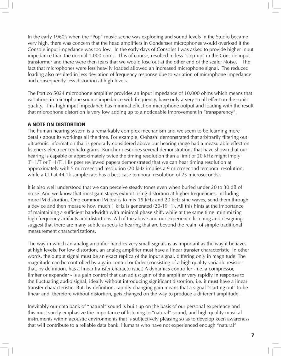
In the early 1960’s when the “Pop” music scene was exploding and sound levels in the Studio became very high, there was concern that the head amplifiers in Condenser microphones would overload if the Console input impedance was too low. In the early days of Consoles I was asked to provide higher input impedance than the normal 1,000 ohms. This of course, resulted in less “step-up” in the Console input transformer and there were then fears that we would lose out at the other end of the scale; Noise. The fact that microphones were less heavily loaded allowed an increased microphone signal. The reduced loading also resulted in less deviation of frequency response due to variation of microphone impedance and consequently less distortion at high levels.
The Portico 5024 microphone amplifier provides an input impedance of 10,000 ohms which means that variations in microphone source impedance with frequency, have only a very small effect on the sonic quality. This high input impedance has minimal effect on microphone output and loading with the result that microphone distortion is very low adding up to a noticeable improvement in “transparency”.
A NOTE ON DISTORTIONThe human hearing system is a remarkably complex mechanism and we seem to be learning more details about its workings all the time. For example, Oohashi demonstrated that arbitrarily filtering out ultrasonic information that is generally considered above our hearing range had a measurable effect on listener’s electroencephalo-grams. Kunchur describes several demonstrations that have shown that our hearing is capable of approximately twice the timing resolution than a limit of 20 kHz might imply(F=1/T or T=1/F). His peer reviewed papers demonstrated that we can hear timing resolution at approximately with 5 microsecond resolution (20 kHz implies a 9 microsecond temporal resolution, while a CD at 44.1k sample rate has a best-case temporal resolution of 23 microseconds).
It is also well understood that we can perceive steady tones even when buried under 20 to 30 dB of noise. And we know that most gain stages exhibit rising distortion at higher frequencies, including more IM distortion. One common IM test is to mix 19 kHz and 20 kHz sine waves, send them through a device and then measure how much 1 kHz is generated (20-19=1). All this hints at the importance of maintaining a sufficient bandwidth with minimal phase shift, while at the same time minimizing high frequency artifacts and distortions. All of the above and our experience listening and designing suggest that there are many subtle aspects to hearing that are beyond the realm of simple traditional measurement characterizations.
The way in which an analog amplifier handles very small signals is as important as the way it behaves at high levels. For low distortion, an analog amplifier must have a linear transfer characteristic, in other words, the output signal must be an exact replica of the input signal, differing only in magnitude. The magnitude can be controlled by a gain control or fader (consisting of a high quality variable resistor that, by definition, has a linear transfer characteristic.) A dynamics controller - i.e. a compressor, limiter or expander - is a gain control that can adjust gain of the amplifier very rapidly in response to the fluctuating audio signal, ideally without introducing significant distortion, i.e. it must have a linear transfer characteristic. But, by definition, rapidly changing gain means that a signal “starting out” to be linear and, therefore without distortion, gets changed on the way to produce a different amplitude.
Inevitably our data bank of “natural” sound is built up on the basis of our personal experience and this must surely emphasize the importance of listening to “natural” sound, and high quality musical instruments within acoustic environments that is subjectively pleasing so as to develop keen awareness that will contribute to a reliable data bank. Humans who have not experienced enough “natural”

8
sound may well have a flawed data bank! Quality recording equipment should be capable of retaining “natural” sound and this is indeed the traditional measuring stick. And “creative” musical equipment should provide the tools to manipulate the sound to enhance the emotional appeal of the music without destroying it. Memory and knowledge of real acoustic and musical events may be the biggest tool and advantage any recording engineer may possess.
One needs to be very careful when one hears traces of distortion prior to recording because some flavors of distortion that might seem acceptable (or even stylish) initially, may later prove to cause irreparable damage to parts of the sound (for example, “warm lows” but “harsh sibilance”) or in louder or quieter sections of the recording. Experience shows that mic preamps and basic console routing paths should offer supreme fidelity otherwise the engineer has little control or choice of recorded “color” and little recourse to undo after the fact. Devices or circuits that can easily be bypassed are usually better choices when “color” is a consideration and this particularly is an area where one might consider comparing several such devices. Beware that usually deviations from linearity carry at least as much long-term penalty as initial appeal, and that one should always be listening critically when recording and generally “playing it safe” when introducing effects that cannot be removed.
1. Tsutomu Oohashi, Emi Nishina, Norie Kawai, Yoshitaka Fuwamoto, and Hishi Imai. National
Institute of Multimedia Education, Tokyo. “High Frequency Sound Above the Audible Range,Affects Brain Electric Activity and
Sound Perception” Paper read at 91st. Convention of the A.E.S.October 1991. Section 7. (1), Conclusion.
2. Miland Kunchur,Depart of Physics and Astronomy, University of South Carolina. “Temporal resolution of hearing probed
by bandwidth restriction”, M. N. Kunchur, Acta Acustica united with Acustica 94, 594–603 (2008) (http://www.physics.
sc.edu/kunchur/Acoustics-papers.htm)
3. Miland Kunchur,Depart of Physics and Astronomy, University of South Carolina.Probing the temporal resolution and
bandwidth of human hearing , M. N. Kunchur, Proc. of Meetings on Acoustics (POMA) 2, 050006 (2008)
5024 FEATURES
MICROPHONE INPUTThe microphone input is balanced but not floating, being a variant of an instrumentation amplifier.Our well-proven “Transformer-Like-Amplifier” (T.L.A.) configuration is used, which includes anaccurate toroidal Common Mode Low Pass Filter that rejects Common Mode signals and excludesfrequencies above 150 kHz. (There are high powered broadcast transmitters at and above thisfrequency in several Continents and, even if you can’t hear them, any vestigial intermodulationproducts must be excluded!)
When the Mic Gain switch is set to Unity (0 dB), the Portico 5024 microphone pre-amplifier can handle a balanced input signal of more than +20 dBu without an input attenuator pad! This is a unique feature that enables this input to double as an additional line input.
THE LINE OUTPUTSThe main output signal comes from the output transformer secondary which is balanced and ground free. A ground free connection guarantees freedom from hum and radio frequency interference when connected to a balanced destination such as the input to another Portico module or a high quality ADC. However the transformer may be used with one leg grounded without any change in performance. It is not necessary to “ground” one leg at the Portico output. It would normally get a ground connection when fed to equipment that is not balanced. Maximum output level is + 26 dBu, which provides a large margin over and above the likely maximum requirement of any destination equipment to which the
9
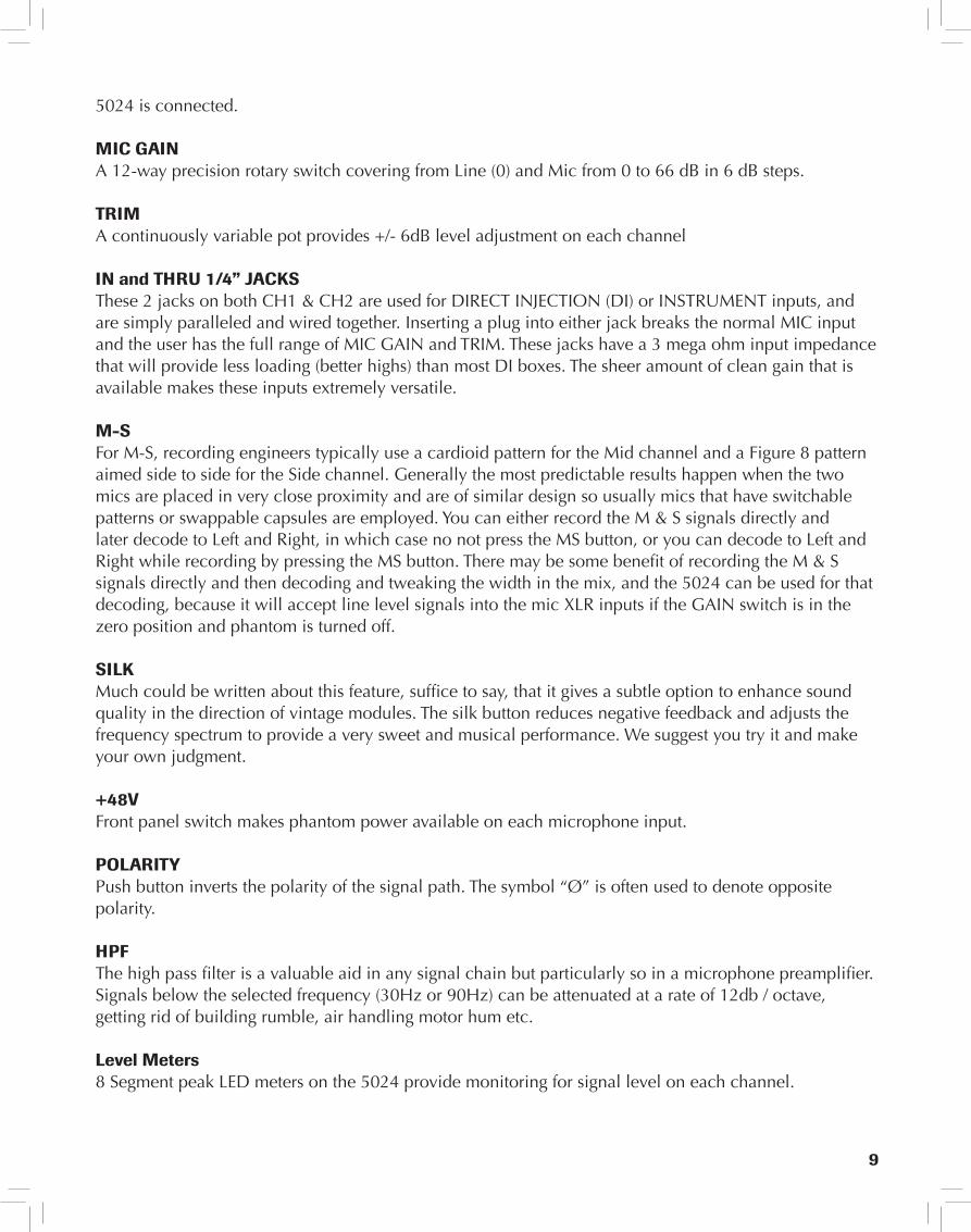
5024 is connected.
MIC GAIN A 12-way precision rotary switch covering from Line (0) and Mic from 0 to 66 dB in 6 dB steps.
TRIMA continuously variable pot provides +/- 6dB level adjustment on each channel
IN and THRU 1/4” JACKSThese 2 jacks on both CH1 & CH2 are used for DIRECT INJECTION (DI) or INSTRUMENT inputs, and are simply paralleled and wired together. Inserting a plug into either jack breaks the normal MIC input and the user has the full range of MIC GAIN and TRIM. These jacks have a 3 mega ohm input impedance that will provide less loading (better highs) than most DI boxes. The sheer amount of clean gain that is available makes these inputs extremely versatile.
M-SFor M-S, recording engineers typically use a cardioid pattern for the Mid channel and a Figure 8 pattern aimed side to side for the Side channel. Generally the most predictable results happen when the two mics are placed in very close proximity and are of similar design so usually mics that have switchable patterns or swappable capsules are employed. You can either record the M & S signals directly and later decode to Left and Right, in which case no not press the MS button, or you can decode to Left and Right while recording by pressing the MS button. There may be some benefit of recording the M & S signals directly and then decoding and tweaking the width in the mix, and the 5024 can be used for that decoding, because it will accept line level signals into the mic XLR inputs if the GAIN switch is in the zero position and phantom is turned off.
SILKMuch could be written about this feature, suffice to say, that it gives a subtle option to enhance sound quality in the direction of vintage modules. The silk button reduces negative feedback and adjusts the frequency spectrum to provide a very sweet and musical performance. We suggest you try it and make your own judgment.
+48V Front panel switch makes phantom power available on each microphone input.
POLARITY Push button inverts the polarity of the signal path. The symbol “Ø” is often used to denote opposite polarity.
HPFThe high pass filter is a valuable aid in any signal chain but particularly so in a microphone preamplifier. Signals below the selected frequency (30Hz or 90Hz) can be attenuated at a rate of 12db / octave, getting rid of building rumble, air handling motor hum etc.
Level Meters8 Segment peak LED meters on the 5024 provide monitoring for signal level on each channel.
10
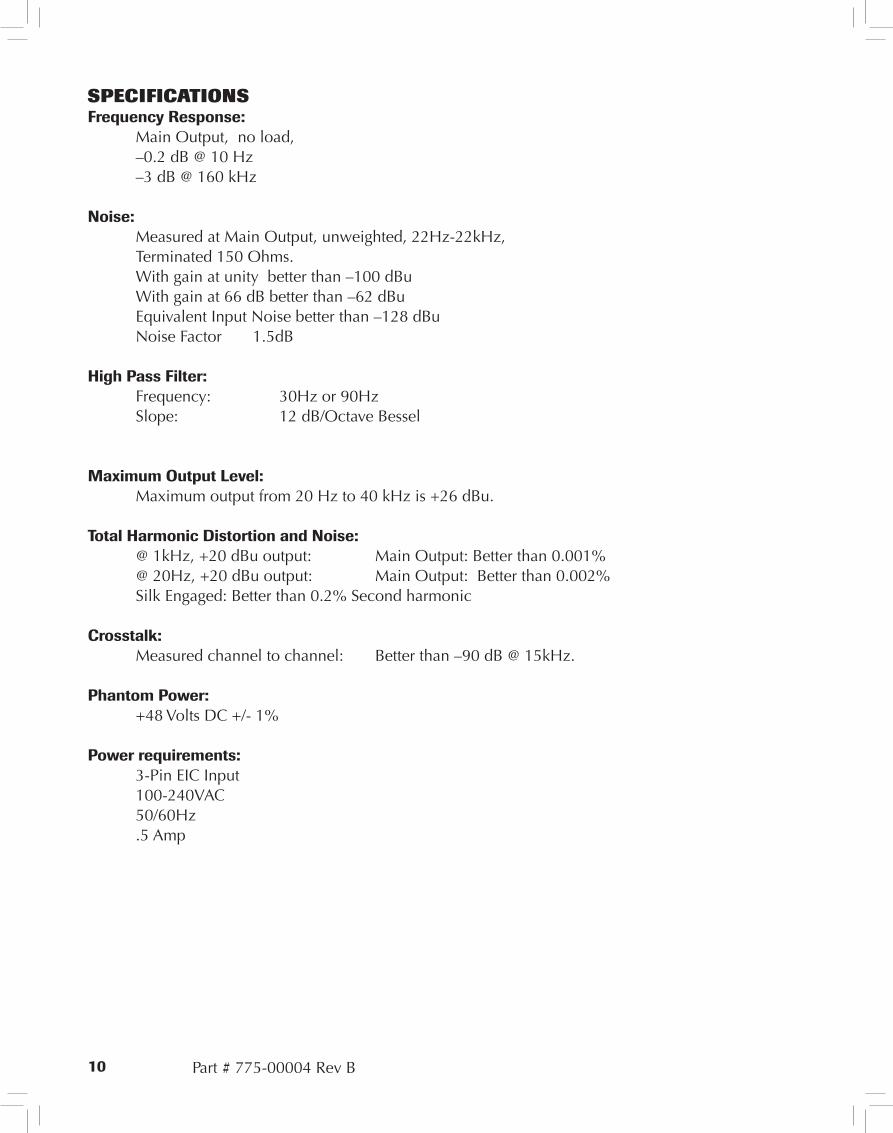
SPECIFICATIONSFrequency Response: Main Output, no load, –0.2 dB @ 10 Hz –3 dB @ 160 kHz
Noise: Measured at Main Output, unweighted, 22Hz-22kHz, Terminated 150 Ohms. With gain at unity better than –100 dBu With gain at 66 dB better than –62 dBu Equivalent Input Noise better than –128 dBu Noise Factor 1.5dB
High Pass Filter: Frequency: 30Hz or 90Hz Slope: 12 dB/Octave Bessel
Maximum Output Level: Maximum output from 20 Hz to 40 kHz is +26 dBu.
Total Harmonic Distortion and Noise: @ 1kHz, +20 dBu output: Main Output: Better than 0.001% @ 20Hz, +20 dBu output: Main Output: Better than 0.002% Silk Engaged: Better than 0.2% Second harmonic
Crosstalk: Measured channel to channel: Better than –90 dB @ 15kHz.
Phantom Power: +48 Volts DC +/- 1%
Power requirements: 3-Pin EIC Input 100-240VAC 50/60Hz .5 Amp
Part # 775-00004 Rev B

PRODUCT WARRANTYRupert Neve Designs warrants this product to be free from defects in materials and workmanship for a period of three (3) years from date of purchase, and agrees to remedy any defect identified within such three year period by, at ouroption, repairing or replacing the product.
LIMITATIONS AND EXCLUSIONS
This warranty, and any other express or implied warranty, does not apply to any product which has been improperly installed, subjected to usage for which the product was not designed, misused or abused, damaged during shipping, damaged by any dry cell battery, or which has been altered or modified in any way. This warranty is extended to the original end user purchaser only. A purchase receipt or other satisfactory proof of date of original purchase is required before any warranty service will be performed. THIS EXPRESS, LIMITED WARRANTY IS IN LIEU OF ALL OTHER WARRANTIES, EXPRESS OR IMPLIED, TO THE EXTEND ALLOWED UNDER APPLICABLE STATE LAW. IN NO EVENT SHALL RUPERT NEVE DESIGNS BE LIABLE FOR ANY SPECIAL, INCIDENTAL, OR CONSEQUENTIAL DAMAGES RESULTING FROM THE USE OF THIS PRODUCT. Some states do not allow the exclusion or limitation of consequential damages or limitations on how long an implied warranty lasts, so this exclusion may not apply to you.
WARRANTY SERVICE
If you suspect a defect in this product, please call us at 512-847-3013 or contact our support staff ([email protected]) for troubleshooting. If it is determined that the device is malfunctioning, we will issue a Return Material Authorization and provide instructions for shipping the device to our service department.
Rupert Neve DesignsPO Box 1969Wimberley TX 78676www.rupertneve.com tel: +1 512-847-3013fax: +1 512-847-8869
775-00004 Rev D