Embed Size (px)
Citation preview
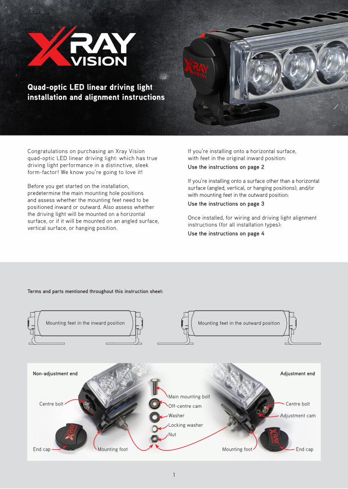
Congratulations on purchasing an Xray Vision quad-optic LED linear driving light: which has true driving light performance in a distinctive, sleek form-factor! We know you’re going to love it!
Before you get started on the installation, predetermine the main mounting hole positions and assess whether the mounting feet need to be positioned inward or outward. Also assess whether the driving light will be mounted on a horizontal surface, or if it will be mounted on an angled surface, vertical surface, or hanging position.
If you’re installing onto a horizontal surface, with feet in the original inward position:
Use the instructions on page 2
If you’re installing onto a surface other than a horizontal surface (angled, vertical, or hanging positions), and/or with mounting feet in the outward position:
Use the instructions on page 3
Once installed, for wiring and driving light alignment instructions (for all installation types):
Use the instructions on page 4
Quad-optic LED linear driving light installation and alignment instructions
1
Terms and parts mentioned throughout this instruction sheet:
Mounting feet in the inward position Mounting feet in the outward position
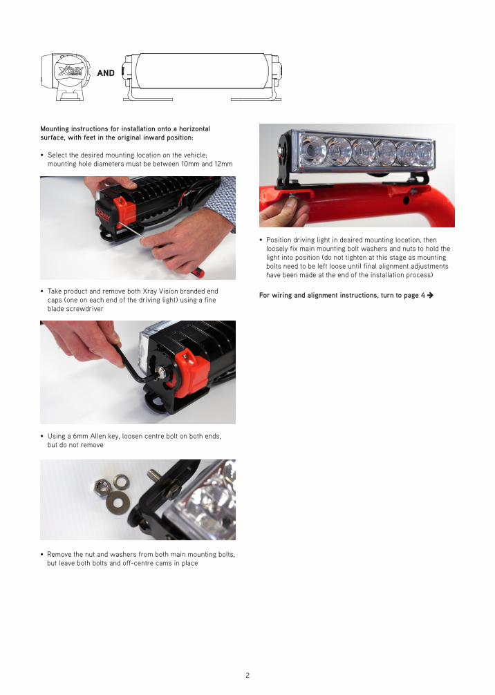
Mounting instructions for installation onto a horizontal surface, with feet in the original inward position:
• Select the desired mounting location on the vehicle; mounting hole diameters must be between 10mm and 12mm
• Take product and remove both Xray Vision branded end caps (one on each end of the driving light) using a fine blade screwdriver
• Using a 6mm Allen key, loosen centre bolt on both ends, but do not remove
• Remove the nut and washers from both main mounting bolts, but leave both bolts and off-centre cams in place
• Position driving light in desired mounting location, then loosely fix main mounting bolt washers and nuts to hold the light into position (do not tighten at this stage as mounting bolts need to be left loose until final alignment adjustments have been made at the end of the installation process)
For wiring and alignment instructions, turn to page 4
2
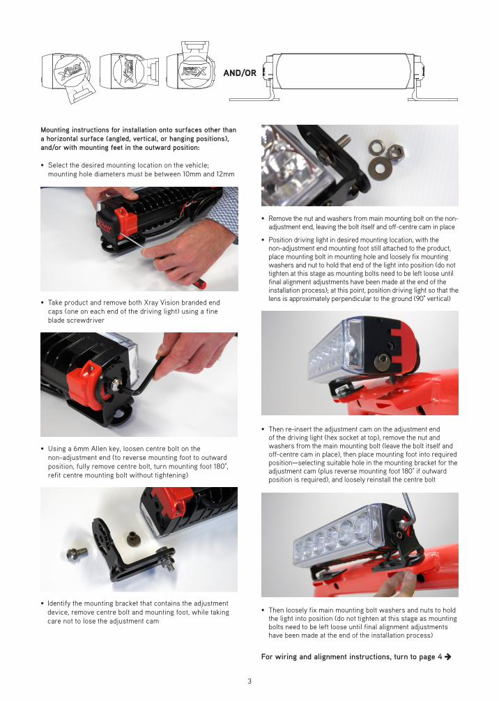
Mounting instructions for installation onto surfaces other than a horizontal surface (angled, vertical, or hanging positions), and/or with mounting feet in the outward position:
• Select the desired mounting location on the vehicle; mounting hole diameters must be between 10mm and 12mm
• Take product and remove both Xray Vision branded end caps (one on each end of the driving light) using a fine blade screwdriver
• Using a 6mm Allen key, loosen centre bolt on the non-adjustment end (to reverse mounting foot to outward position, fully remove centre bolt, turn mounting foot 180°, refit centre mounting bolt without tightening)
• Identify the mounting bracket that contains the adjustment device, remove centre bolt and mounting foot, while taking care not to lose the adjustment cam
• Remove the nut and washers from main mounting bolt on the non-adjustment end, leaving the bolt itself and off-centre cam in place
• Position driving light in desired mounting location, with the non-adjustment end mounting foot still attached to the product, place mounting bolt in mounting hole and loosely fix mounting washers and nut to hold that end of the light into position (do not tighten at this stage as mounting bolts need to be left loose until final alignment adjustments have been made at the end of the installation process); at this point, position driving light so that the lens is approximately perpendicular to the ground (90° vertical)
• Then re-insert the adjustment cam on the adjustment end of the driving light (hex socket at top), remove the nut and washers from the main mounting bolt (leave the bolt itself and off-centre cam in place), then place mounting foot into required position—selecting suitable hole in the mounting bracket for the adjustment cam (plus reverse mounting foot 180° if outward position is required), and loosely reinstall the centre bolt
• Then loosely fix main mounting bolt washers and nuts to hold the light into position (do not tighten at this stage as mounting bolts need to be left loose until final alignment adjustments have been made at the end of the installation process)
For wiring and alignment instructions, turn to page 4
3
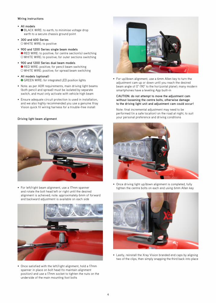
• For up/down alignment, use a 6mm Allen key to turn the adjustment cam up or down until you reach the desired beam angle of 0° (90° to the horizontal plane); many modern smartphones have a leveling App built-in
CAUTION: do not attempt to move the adjustment cam without loosening the centre bolts, otherwise damage to the driving light unit and adjustment cam could occur!
Note: final incremental adjustment may need to be performed (in a safe location) on the road at night, to suit your personal preference and driving conditions
• Once driving light up/down alignment is completed, fully tighten the centre bolts on each end using 6mm Allen key
• Lastly, reinstall the Xray Vision branded end caps by aligning two of the clips, then simply snapping the third back into place
Wiring instructions
• All models BLACK WIRE: to earth; to minimise voltage drop earth to a secure chassis ground point
• 300 and 600 Series WHITE WIRE: to positive
• 900 and 1200 Series single beam models RED WIRE: to positive; for centre section(s) switching WHITE WIRE: to positive; for outer sections switching
• 900 and 1200 Series dual beam models RED WIRE: positive; for pencil beam switching WHITE WIRE: positive; for spread beam switching
• All models (optional) GREEN WIRE: for integrated LED position lights
• Note: as per ADR requirements, main driving light beams (both pencil and spread) must be isolated by separate switch, and must only activate with vehicle high beam
• Ensure adequate circuit protection is used in installation, and we also highly recommended you use a genuine Xray Vision quick fit wiring harness for a trouble-free install
Driving light beam alignment
• For left/right beam alignment, use a 17mm spanner and rotate the bolt head left or right until the desired alignment is acheived; note: approximately 6mm of forward and backward adjustment is available on each side
• Once satisfied with the left/right alignment, hold a 17mm spanner in place on bolt head (to maintain alignment position) and use a 17mm socket to tighten the nuts on the underside of the main mounting foot bolts
4