Embed Size (px)
Citation preview
Faculdade de Engenharia da Universidade do Porto
QuadAALper – The Ambient Assisted Living
Quadcopter
Ricardo Miguel Gradim Nascimento
Mestrado Integrado em Engenharia Electrotécnica e de Computadores
Fraunhofer Supervisor: Eng. Bernardo Pina
FEUP Supervisor: Ph.D. Prof. António Paulo Moreira
15th of April 2015

© Ricardo Miguel Nascimento, 2015
i

i
Resumo
Nesta dissertação é implementado um sistema para permitir a navegação autónoma de um
quadcopter em ambientes sem sinal GPS nomeadamente espaços indoor. Tirando partido de um
ambiente condicionado com QR codes no tecto, um telemóvel colocado a bordo do quadcopter
realiza a detecção e descodificação dos códigos que contêm informação sobre a localização
absoluta no ambiente de teste. A informação recolhida é utilizada para criar um falso sinal GPS
que ajuda a corrigir os errros de posição provocados pelo controlador do quadcóptero usando um
EKF que realiza a fusão dos dados da IMU com o sinal GPS para corrigir a posição e orientação.
O protocolo de transferência de dados geográficos usado é NMEA. O protocolo MAVLink é
também integrado na aplicação para permitir a comunicação com o quadcopter de forma a
possibilitar o planeamento de missões e a troca de informação de telemetria para monotorização
durante o voo. O sistema utiliza apenas componentes a bordo do quadcopter para processemanto
não estando dependente de qualquer tipo de estação monitora fora do quadcopter ou sinal wi-fi
para transmissão de dados. Toda a transferência de dados é realizada via USB para série. Os
resultados são promissores e promovem a utilização de telemóveis a bordo do quadcopter para
tarefas de localização e mapeamento tirando partido do processador e câmera do telemóvel

ii
iii
Abstract
In this thesis is implemented a system to allow autonomous navigation of a quadcopter in
GPS denied environments using a mobile device on-board. By taking advantage of a pre-
conditioned environment, a mobile device attached to the top platform of a quadcopter tracks QR
codes in the ceiling that contain information about the precise location in the environment. The
information is used to create a fake GPS signal that then is applied to correct the measures of the
inertial sensors using an EKF implemented in the Pixhawk. The geographic information
transferred from the mobile device respects the NMEA protocol. Also the MAVLink protocol is
integrated in the application to enable mission planning with selected waypoints and receive live
telemetry data for analysis and monitorization of Pixhawk status. The system uses only on-board
equipment for processing as the mobile device and the Pixhawk do all the computational effort.
The promising results allow to open the possibility of the usage of mobile devices on air, taking
advantage of the camera and the processing board to perform localization and mapping tasks.

iv
v
Agradecimentos
Aos orientadores, Professor António Paulo Moreira da parte da FEUP e Eng. Bernardo Pina da
parte da Fraunhofer pelo apoio dado durante a dissertação. Ao Eng. André Pereira da Fraunhofer
pelo tempo disponibilizado, visto que não sendo orientador, prestou uma enorme ajuda. Ao James
Overington do forúm DIY Drones pelas inúmeras discussões, sugestões e conselhos sobre a
melhor solução para o projecto. Sem estas contribuições, o resultado final seria certamente
bastante diferente.
Aos meus amigos e especialmente à minha familia por todo o apoio dado durante a dissertação.
Ricardo Miguel Nascimento

vi
vii
“Our passion for learning is our tool for survival”
Carl Sagan

viii
ix
Contents
1 Introduction………………………………………………………………………........... 1
1.1 Motivation ....................................................................................................................................... 2 1.2 Context ............................................................................................................................................ 2
1.3 Objectives ........................................................................................................................................ 2 1.4 Document Outline ............................................................................................................................ 4
2 State of Art………………………………………………..………………………………. 5 2.1 Robots as Ambient Assisted Living (AAL) Tool……………………………………......................5
2.2 Quadcopters……………………………………………………………………………….……..…7
2.3 Solutions for autonomy…………………………………………………………………...……….13
2.4 Utility of the Smartphone for a Quadcopter……………………………………………...…..........20
2.5 Summary...……..........................…………………………………………………........……….... 24
3 System Specification………………………...…………………………………………...25
3.1 Overview of Considered Solutions ................................................................................................ 25
3.2 Solution Based in Artificial Markers ............................................................................................. 30 3.3 System Architecture....................................................................................................................... 32
3.4 System Specification Details ......................................................................................................... 34 3.5 OpenCV ......................................................................................................................................... 39 3.6 Mission Planner ............................................................................................................................. 39
3.7 Summary ........................................................................................................................................ 40
4 System Implementation……………………..…………………………………………...41 4.1 Assembling Hardware Connections……………………………………………………...………..41 4.2 Quadcopter Setup........................................................................................................................... 43
4.3 Mobile Application ........................................................................................................................ 45 4.4 Obstacle Avoidance with Infra-Red Sensors ................................................................................. 61 4.5 Summary ........................................................................................................................................ 61
5 System Evaluation…………...…………………………………………………………...63
5.1 Test environment ........................................................................................................................... 63
5.2 Test Cases ...................................................................................................................................... 64 5.3 Results ........................................................................................................................................... 65
5.4 Discussion ...................................................................................................................................... 76 5.5 Limitations ..................................................................................................................................... 78
6 Results and Future Work………………………………………………………………..79
7 References………………………………………………………………………………...81

x
xi
List of Figures
Figure 2.1 - AAL Robots: (a) – Care-O-Bot; (b) – PerMMa ................................................ 6
Figure 2.2 - Situations where the quadcopter can be useful: (a) - House after earthquake; (b)
- Stairs ..................................................................................................................................... 8
Figure 2.3 - Commercial Solutions: (a) - Firefly (b) - Hummingbird (c) - Pelican (d) - Parrot
2.0 (e) - Crazyflie (f) - Iris .................................................................................................... 12
Figure 2.4 - Generated 3D map of the surrounding environment (Weiss, Scaramuzza, and
Siegwart 2011) ...................................................................................................................... 15
Figure 2.5 - Map generated with information from laser scanner ........................................ 16
Figure 2.6 - Map generated with information from RGB-D camera (Henry et al.) ............. 17
Figure 2.7 - Trajectory of the vehicle during navigation and collision avoidance (Chee and
Zhong 2013) .......................................................................................................................... 18
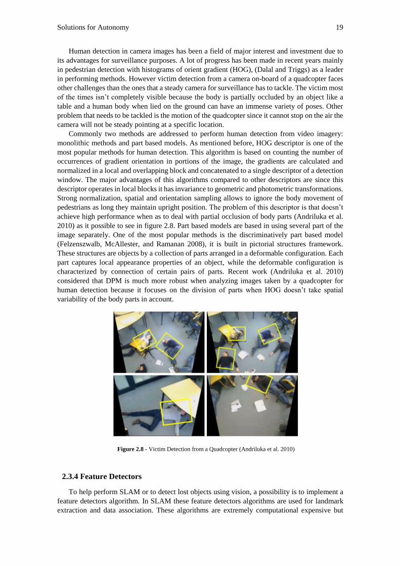
Figure 2.8 - Victim Detection from a Quadcopter (Andriluka et al. 2010) .......................... 19
Figure 2.9 - Coordinate System used by Android API (Lawitzki 2012) .............................. 21
Figure 3.1 - Screenshot Mission Planner Enable EKF ......................................................... 30
Figure 3.2 - Solution Overview ............................................................................................ 30
Figure 3.3 - QR Code ........................................................................................................... 31
Figure 3.4 - QR Code grid map on the ceiling with cm displacement ................................. 32
Figure 3.5 - System Overview ............................................................................................. 33
Figure 3.6 - Arducopter ........................................................................................................ 35
Figure 3.7 - HTC One M8 .................................................................................................... 35
Figure 3.8 - Pixhawk ............................................................................................................ 37
Figure 3.9 - Sonar sensor ..................................................................................................... 38
Figure 3.10 - IR sensor ......................................................................................................... 39
Figure 4.1 - Assembly of the Quadcopter - 1 ....................................................................... 42
Figure 4.2 - Assembly of the Quadcopter - 2 ....................................................................... 42
xii
Figure 4.3 - Screenshot Mission Planner Firmware Selection ............................................. 43
Figure 4.4 - Screenshot Mission Planner RC Calibration .................................................... 43
Figure 4.5 - Screenshot Mission Planner Compass Selection .............................................. 44
Figure 4.6 - Screenshot Mission Planner Frame Type Selection ......................................... 44
Figure 4.7 - Screenshot Mission Planner PID Calibration ................................................... 45
Figure 4.8 – Application Overview ...................................................................................... 46
Figure 4.9 - QR Code markers ............................................................................................. 47
Figure 4.10 - QR code orientation label ............................................................................... 48
Figure 4.11 - Screenshot of the contour around the markers ............................................... 48
Figure 4.12 - Horizontal displacement ................................................................................. 49
Figure 4.13 - Checkerboard used for calibration .................................................................. 50
Figure 4.14 - Result of the calibration.................................................................................. 50
Figure 4.15 – Regression Chart ............................................................................................ 51
Figure 4.16 - Angle of the QR Code .................................................................................... 53
Figure 4.17 - Displacement example .................................................................................... 53
Figure 4.18 - Waypoint Sequence of Messages .................................................................. 58
Figure 4.19 - Path made by the quadcopter in autonomous mode ...................................... 58
Figure 4.20 - Screenshot of MAVLink messages sent by the Pixhawk received by the
application ............................................................................................................................. 59
Figure 4.21 - Obstacle avoidance example during mission .................................................. 61
Figure 5.1 - Test Environment ............................................................................................. 63
Figure 5.2 - Orientation of the Mobile Device ..................................................................... 65
Figure 5.3 - Hit rate of decoding for several distances ........................................................ 67
Figure 5.4 - Hit rate of decoding for various code orientations ........................................... 68
Figure 5.5 - Hit rate of decoding for several mobile device orientations ............................. 68
Figure 5.6 - Hit rate of decoding for several light conditions .............................................. 68
Figure 5.7 - Hit rate of decoding for several mobile device speed movements ................... 69
Figure 5.8 - Screenshot of the application detecting a body lied on the ground .................. 70
Figure 5.9 - Screenshot of GPS Fix on Mission Planner after first detection ...................... 71
Figure 5.10 - GPS Signal Analysis ...................................................................................... 72
Figure 5.11 - Latitude and Longitude signals in Mission Planner ....................................... 72
Figure 5.12 - Latitude Signal in Mission Planner ................................................................ 72
Figure 5.13 - Sonar and Barometer Signals 1 ...................................................................... 73
Figure 5.14 - Sonar and Barometer Signals 2 ...................................................................... 73
Figure 5.15 - Sonar and Barometer Signals 3 ...................................................................... 74
Figure 5.16 – Comparison of each pipeline duration for different smartphones .................. 76
xiii
List of Tables
Table 3.1 - APM 2.5 and Pixhawk features .......................................................................... 37
Table 4.1 - Values for distance considering the area ............................................................ 50
Table 4.2 - NMEA GGA message protocol ......................................................................... 54
Table 4.3 - NMEA VTG message protocol .......................................................................... 54
Table 4.4 - NMEA RMC message protocol ......................................................................... 55
Table 5.1 – Detection for several distances .......................................................................... 66
Table 5.2 - Detection for several code orientations .............................................................. 66
Table 5.3 - Detection for several mobile device orientations ............................................... 66
Table 5.4 - Detection for several light conditions ................................................................ 66
Table 5.5 - Detection for several type of mobile device speed movements ......................... 67
Table 5.6 - Compare Estimated Distance with Actual Distance with Perpendicular View.. 69
Table 5.7 - Compare Estimated Distance with Actual Distance with Oblique View ........... 69
Table 5.8 - Victim Detection on Wooden Floor ................................................................... 70
Table 5.9 - Victim detection in carpet with several patterns ................................................ 70
Table 5.10 - HTC M8 versus Moto G features ..................................................................... 75
Table 5.11 - HTC M8 10 fps performance ........................................................................... 75
Table 5.12 – HTC M8 20 fps performance .......................................................................... 75
Table 5.13 - Moto G 2013 8 fps performance ...................................................................... 75
Table 5.14 - Moto G 2013 13 fps performance .................................................................... 76

xiv
xv
Abbreviations
AAL Ambient Assisted Living
ADL Activity Daily Living
APM ArduPilot Mega
CPU Central Processing Unit
DPM Deformed Part Model
EADL Enhanced Activity Daily Living
EKF Extended Kalman Filter
FAST Features from Accelerated Segment Test
FEUP Faculdade Engenharia da Universidade do Porto
GPS Global Positioning System
HOG Histogram Oriented Gradient
IADL Instrumental Activity Daily Living
IR Infra-Red
IMU Inertial Measuring Unit
MAV Micro Aerial Vehicle
MCL Monte Carlo Localization
OTG On the Go
RAM Random Access Memory
VSLAM Visual Simultaneous Localization and Mapping
SIFT Scale Invariant Feature Transform
SLAM Simultaneous Localization and Mapping
SURF Speeded-Up Robust Feature
UAV Unmanned Aerial Vehicle
USB Universal Serial Bus

xvi
1
Chapter 1
Introduction
The aging of world population is one toughest challenges our generation as to face due to its
consequences in a range of social, political and economic processes. In developed countries,
population has been aging for a large number of decades and in the ones who are developing
aging is recent due to the downfall of the mortality and fertility taxes. This leads to an increase in
the main working class and in the elderly population. The global share of people aged 60 or more
boosted from 9.2% in 1990 to 11.7% in 2013 and previsions aim that by 2050 will be 21.1% as
the number of people aging 60 or more is expected to double by that date (United Nations 2013).
The growth of the number of people affected by chronic diseases such Alzheimer and Parkinson
(Rashidi et al. 2013) also increase the challenge of developing solutions to monitor and help these
patients. Creating resources to allow the elderly to have comfort and dignity at a social level but
also to spare them of the costs of a private nurse or hospitalization is a challenge to engineering
as technology carries a heavy burden in this subject.
In recent times, the advance on areas like smart homes (Ojasalo and Seppala 2010) or
wearable sensors (Pantelopoulos and Bourbakis 2010) gained a lot of importance and allowed
elderly to live at their homes without the needs of going to their family house or to a nursing
home. Also several companies around the world developed robots (Mukai et al. 2010) to assist
on tasks as preparing meals, helping with the bathing, dressing or catching specific objects.
Image processing algorithms can be used in situations such as victim detection on the ground,
tracking the elderly in indoor environments to supervise their tasks or detecting lost objects. These
computational techniques play a lead role in providing safety and quality life but also are relative
low cost when compared to sensors that track human activity.
This document explores the application of a quadcopter to ALL scenarios with a development
of a system to allow autonomous navigation in GPS denied environments. The implemented
system is based in computer vision with a smartphone running image processing algorithms on-
board as a low cost resource to provide intelligence. The method followed in this dissertation is
different from the most common approaches to implement an indoor navigation system. This
approach takes advantage of the powerful processor and camera of the mobile device to run
computer vision algorithms and doesn’t require a ground station to monitor the quadcopter and
doesn’t rely on Wi-Fi signal as all the processing is done on-board and all data transfer is done
via USB to serial. This dissertation was developed at Fraunhofer Portugal Research Association.
2 Introduction
1.1 Motivation
The development of a vision system for a quadcopter provides an extra solution to the AAL
scenarios in a near future. Most of the robots developed to AAL operate on the ground where they
face a complicate environment with lot of obstacles that create limitations to their movement.
Taking advantage of its flying abilities, the quadcopter can avoid ground obstacles and fly freely
through indoor divisions. This can be helpful when tracking people through doors, stairs or to
carry small objects like keys from one division to another.
Generally the data coming from the quadcopter camera and sensors is computed off-board by
an external ground station due to the fact that is needed a high data processor to cross the
information coming from the sensors. This strategy offers problems because there is a dependency
on a wireless network for data transfer and a delay generated by data transmission that can be
harmful as the quadcopter can’t stop in the air waiting for information. Other limitation is that
GPS is not accurate in indoor environments so localization has to be done using data provided by
the sensors on-board of the quadcopter. Recent work (Achtelik et al. 2011) showed powerful on-
board solutions for position and orientation estimation to allow simultaneous localization and
mapping (SLAM). SLAM problem can be addressed using vision with an on-board camera, laser
scanners, sonars or RGB-D cameras. Each approach has its advantages and disadvantages and
this dissertation is looking for the most flexible, efficient and low cost solution. Nowadays
smartphones have powerful processors and are widely spread over the world so they can function
as central processing unit on-board for this dissertation as they contribute to flexibility and to a
low cost platform. Also the smartphone has a camera, sensors, processing unit and communication
system built-in so it’s possible to spare on the vertical weight of the quadcopter. The security
problem will not be addressed on this dissertation but will be an aspect for future consideration
since the quadcopter has to guarantee safety requisites to don’t cause harm to people, damage
objects or equipment.
This dissertation is driven by the chance to offer an extra solution to the AAL scenarios with
a low cost, autonomous and flexible platform.
1.2 Context
Recently, several companies and institutes have applied a big part of its resources on
developing products and services that allow elderly people to have an independent and socially
active life. Mainly the solutions aim at improving comfort at home through intelligent
environments. The rehabilitation and prevention on a medical level are also a concern as
organizations seek solutions for those who need daily medical care and for the ones who are
physically incapacitated.
It’s in the search of a smart environment able to answer to the consequences of aging that
rises this dissertation. Combining the advantages of a flying robot with the intelligence provided
by the smartphone it’s possible to create a solution that assists and monitors the elderly in daily
tasks.
1.3 Objectives
The main goal of this dissertation is to design, implement and evaluate a vision based system
to allow indoor autonomous navigation in GPS denied environments. The following objectives
are expected to be accomplished at the end of the dissertation:
Objectives 3
O1. To design, implement and test a vision-based localization system to allow autonomous
indoor navigation in a pre-conditioned environment using only components on-board of the
quadcopter.
O2. To implement two communication protocols between the flight controller and the mobile
device: one to allow the exchange of telemetry data for mission planning and monitorization and
other to send the absolute geographic coordinates to allow position estimate.
O3. To evaluate the use of smartphone as on-board processing unit and camera of a
quadcopter.
O4. To propose a human body detection vision-based algorithm for Android to detect a person
lied on the floor from the quadcopter.
O5. To propose an obstacle avoidance algorithm using low-cost sensors for the quadcopter to
be able to cope with the complexity of indoor environments.
The dissertation will lead to the application of the following use cases. The use cases are
specifically designed to proof that the quadcopter can provide an extra solution to AAL scenarios.
UC1. Fall/Faint Situation
1. The user arrives home, connects the smartphone to the quadcopter and goes to the
bedroom. Suddenly he feels bad, faints and fells on the floor. The body sensor detects the
fall and communicates to the base station (smartphone).
2. The smartphone receives the alert and gives order to the quadcopter to address the
division of the house where the elder is.
3. When the quadcopter enters the division where the elder is, the quadcopter recognizes
him using smartphone’s camera and lands with a safe distance.
4. The elder:
4.1 Feels better and is able to get up and press a button on the smartphone to prove he is safe.
4.2 Does not respond.
5. The system:
5.1 Registers the situation of fall but does not act.
5.2 Alerts the caretaker with a video call.
UC2. Gas Sensor
1. The user arrives home, connects the smartphone to the quadcopter and goes to the kitchen
to cook a meal.
2. The gas sensor on board the quadcopter detects that a danger level has been reached.
3. The smartphone launches an alarm.
4. The elder:
4.1 Turns off the alarm.
4.2 Does not act.
5. The system:
5.1 Registers the situation but does not act.
5.2 Turns off the gas and sends a notification to the caretaker.
UC3. Temperature Sensor
1. The user arrives home, connects the smartphone to the quadcopter and goes to the kitchen
to cook a meal.
2. The temperature sensor on board the quadcopter detects that a danger level has been
reached.
3. The smartphone launches the alarm.
4. The elder:
4.1 Turns off the alarm.
4 Introduction
4.2 Does not act.
5. The system:
5.1 Registers the situation but does not act.
5.2 Turns off the oven and sends a notification to the quadcopter.
UC4. Voice Commands
1. The user arrives home and connects the smartphone to the quadcopter.
2. The elder gives an order to the quadcopter (e.g. “Move to division X”).
3. The smartphone:
3.1 Interprets the command and goes to the desired division.
3.2 Does not interpret due to an error.
UC5. Project images and video calls using Galaxy Beam
1. The user arrives home and connects the smartphone to the quadcopter.
2. The elder receives a request for a video call.
3. The elder:
3.1 Picks up.
3.2 Does not pick up.
4. The system:
4.1 Projects the video call on the wall.
4.2 Does not act.
UC6. Facial Recognition
1. The user comes home and connects the smartphone to the quadcopter and goes for a rest
in his bedroom.
2. Someone (unknown or the elder) addresses the quadcopter to pick up the smartphone.
3. The system:
3.1 Recognizes the elder and turns off the alarm system.
3.2 Does not recognize the elder and launches the alarm.
1.4 Document Outline
This chapter provides a detailed description of the main goals of this thesis, my motivations
and explains why AAL is an urgent theme. Chapter 2 presents a summary of the studied literature
on robots applied to AAL, an overview on quadcopters, autonomous navigations systems and
explores the utility of a smartphone for a quadcopter. Chapter 3 describes the system specification
to reach the proposed objectives with the proposed solution and the components used to reach the
solution. Chapter 4 addresses how the system was implemented, which methods were used, the
advantages and disadvantages of the proposed solution. Chapter 5 presents the test environment,
the test cases, the results of the implemented system with a discussion of the results and limitations
of the system. Chapter 6 presents a conclusion for the dissertation and possible future work.
5
Chapter 2
State of Art
This chapter documents the research made prior to the implementation of the project
QuadAALper – The Ambient Assisted Living Quadcopter. First section provides an overview of
robots developed for AAL environments, their major applications and a brief look at the future of
robotics for AAL. Second section approaches the major tackles aerial robots have to face when
compared to ground robots but also their advantages and why they can be extremely useful. The
next topic reviews solutions and techniques to provide the quadcopter the ability to make an
autonomous flight. In the end, this section studies the possibility of integrating a smartphone on-
board of the quadcopter by analyzing the sensors built-in and the processing capacity.
2.1 Robots as Ambient Assisted Living (AAL) Tool
The ability to create solutions to AAL environments has been an area of extensive research in
the last decade. With the aging of world population, engineering faces new challenges and is
responsible to offer low cost health solutions able to help elderly and people who suffer from
chronic diseases.
The costs of having a home nurse care or even hospitalization are very high to common
citizens as most of the population don’t have the money to afford personal treatment. For the last
thirty years robots have been replacing humans in factories for mass production so engineering
started to look for a way to place them in a house environment where they can interact with
humans and help them in some tasks.
Rhino (Buhmann, Burgard, and Cremers 1995) was one of the first autonomous robots to be
placed in public areas, in this particular case a museum, with the purpose of interacting with
people. Rhino operated as tour guide but wasn’t capable of learning anything from the interaction
and had limited communication abilities. However his architecture integrated localization,
mapping, collision avoidance, planning and modules related to human interaction that are still
used today in AAL robotics. Museum visitants were fascinated with Rhino interacting abilities
and the museum attendance raised 50% that year. Rhino was the first of many robots that were
developed with the purpose of human interaction (Siegwart et al. 2003), (Thrun 2000), but they
were far away of being capable to serve as health assistant since the ability to interact with objects
didn’t exist. The need to develop a robot capable of doing tasks like fetch-carry or serve drinks
led to Care-o-Bot (Reiser et al. 2009). This was one of the first assistant robots, with his hands he
6 State of Art
was capable of carrying an elderly from a wheelchair to a bed. Other robots (Kuindersma and
Hannigan 2009) with similar capacities of transporting and placing objects were applied to AAL
since then.
The several number of tasks a robot can develop in AAL environments led to a division in
three categories (Rashidi and Mihailidis 2013): robots designed for daily living activities (ADL),
instrumental activities of daily living (IADL) and enhanced activities of daily living (EADL).
ADL tasks include actions of daily life such as help humans dressing, eating or taking bath. These
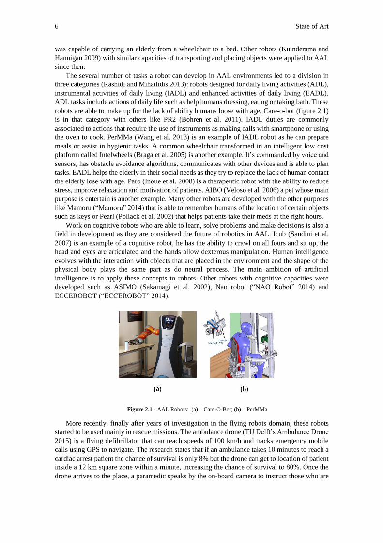
robots are able to make up for the lack of ability humans loose with age. Care-o-bot (figure 2.1)
is in that category with others like PR2 (Bohren et al. 2011). IADL duties are commonly
associated to actions that require the use of instruments as making calls with smartphone or using
the oven to cook. PerMMa (Wang et al. 2013) is an example of IADL robot as he can prepare
meals or assist in hygienic tasks. A common wheelchair transformed in an intelligent low cost
platform called Intelwheels (Braga et al. 2005) is another example. It’s commanded by voice and
sensors, has obstacle avoidance algorithms, communicates with other devices and is able to plan
tasks. EADL helps the elderly in their social needs as they try to replace the lack of human contact
the elderly lose with age. Paro (Inoue et al. 2008) is a therapeutic robot with the ability to reduce
stress, improve relaxation and motivation of patients. AIBO (Veloso et al. 2006) a pet whose main
purpose is entertain is another example. Many other robots are developed with the other purposes
like Mamoru (“Mamoru” 2014) that is able to remember humans of the location of certain objects
such as keys or Pearl (Pollack et al. 2002) that helps patients take their meds at the right hours.
Work on cognitive robots who are able to learn, solve problems and make decisions is also a
field in development as they are considered the future of robotics in AAL. Icub (Sandini et al.
2007) is an example of a cognitive robot, he has the ability to crawl on all fours and sit up, the
head and eyes are articulated and the hands allow dexterous manipulation. Human intelligence
evolves with the interaction with objects that are placed in the environment and the shape of the
physical body plays the same part as do neural process. The main ambition of artificial
intelligence is to apply these concepts to robots. Other robots with cognitive capacities were
developed such as ASIMO (Sakamagi et al. 2002), Nao robot (“NAO Robot” 2014) and
ECCEROBOT (“ECCEROBOT” 2014).
Figure 2.1 - AAL Robots: (a) – Care-O-Bot; (b) – PerMMa
More recently, finally after years of investigation in the flying robots domain, these robots
started to be used mainly in rescue missions. The ambulance drone (TU Delft’s Ambulance Drone
2015) is a flying defibrillator that can reach speeds of 100 km/h and tracks emergency mobile
calls using GPS to navigate. The research states that if an ambulance takes 10 minutes to reach a
cardiac arrest patient the chance of survival is only 8% but the drone can get to location of patient
inside a 12 km square zone within a minute, increasing the chance of survival to 80%. Once the
drone arrives to the place, a paramedic speaks by the on-board camera to instruct those who are
Quadcopters 7
helping the victim. This is a demonstration of the amazing potential drones can offer to specific
situations to improve population quality and safe life.
2.2 Quadcopters
2.2.1 Overview
All the robots mentioned in the previous section developed for AAL scenarios are ground
robots with the exception of the recently developed ambulance drone. Although they aren’t a
common choice for ALL, flying robots have been a field of research for the last decades. Their
amazing features like high mobility and high speed puts them in the front row for numerous
applications. In the last decade, engineers managed to deliver autonomy to flying robots, meaning
that they can collect information about the surrounding environment, work innumerous time
without human interference, ability to create a path to a desired place avoiding possible obstacles
on the way and avoid being harmful to humans. This autonomy is very interesting to ALL
environments since they can help monitor the elderlies when they are at home or provide indoor
guidance through the house even if it has stairs, find lost objects and fetch them, detect alarm
situations or fall situations. These possible applications can be achieved using only one camera
on-board to sense the environment and one powerful CPU to process data captured by the camera.
The problem of developing autonomous robots able to respond to AAL is that implies a
knowledge of several number of complex subjects such as motion, localization, mapping,
perception sensors, image processing techniques and others. The applications of these techniques
are independent to each robot category since ground robots operate differently than flying robots.
The security is also a question that is important to address as flying robots are considerably more
dangerous than ground robots. While the ground robot is perfectly stable on the ground and is
difficult to cause any harm to someone, flying robots can crash from high distances and cause
injuries due to the sharp propellers. These safety questions are one of the main reasons why drones
aren’t still allowed to fly for commercial purposes. An example is the delivery of packages via
drones presented by Amazon (“Amazon Prime Air” 2015) that still hasn’t seen daylight because
of security reasons.
Unmanned Aerial Vehicles (UAVs) commonly named as drone or remotely pilot aircraft
(RPA) are flying robots whose flight can be autonomous or controlled by remote control.
Developed by the United States government back in the 60’s to reduce the number of pilot victims
when flying hostile territory, its applications have been largely explored. These aircrafts have
been a field of extensive research since UAVs can be very helpful performing tasks as
surveillance, military applications where is dangerous sending people, weather observation, civil
engineering inspections, rescue missions and firefighting. These UAVs had big dimensions and
were heavy and capable of carrying powerful on-board computers and a lot of sensor weight to
provide fully autonomous flight with obstacle avoidance techniques. Recent work on Micro
Aerial Vehicles (MAVs) has been the focus of the research community since their small size
provide flights in complex environments with a lot of obstacles and navigation in confined spaces.
However MAVs have limited payload limitations and aren’t able to carry heavy sensor hardware
or heavy computer boards capable of running powerful algorithms, so techniques developed for
UAVs needed specific adaptations to provide the same results on MAVs.
2.2.2 Challenges
In rough terrain, ground robots face a lot of limitations because of the difficulty to perform
tasks like climbing rocks or even in complex indoor environments where there are stairs and doors
8 State of Art
they have limited mobility. MAVs can provide a good solution in those environments as they
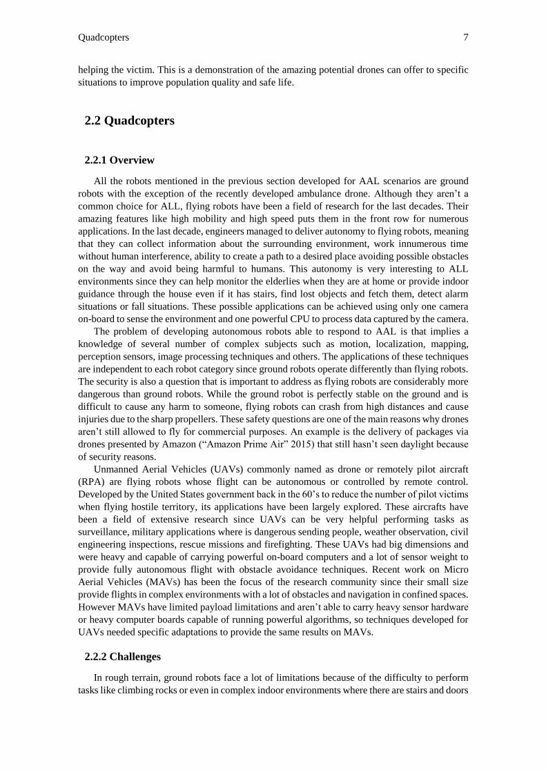
have an outstanding mobility. Figure 2.2 illustrates situations where quadcopters can be useful.
Figure 2.2 - Situations where the quadcopter can be useful: (a) - House after earthquake; (b) - Stairs
Navigation – the ability the robot has to determine his own position in its frame of reference
and then reach a desired location in unsupervised manner without human interference - in outdoor
environments where Global Positioning System (GPS) is available has reached excellent
performance levels but most indoor environments and urban-canyons are GPS-denied so there’s
no access to external positioning. This is one of the few challenges MAVs have to tackle. The
challenges of MAVs able to fly in indoor environments compared to ground robots are the
following (Bachrach 2009):
Limited Sensing Payload
When compared to ground vehicles MAVs have limited vertical weight so they can
perform a stable flight. While ground robots are heavy and can sustain an amount of heavy
payload sensors like SICK lasers scanners, high fidelity Inertial Measurement Unit (IMU)
– device that measures velocity, orientation and gravitational forces using a combination
of accelerometers, gyroscope and also magnetometers - and large cameras, MAVs can’t
sustain that amount of payload so it’s necessary to look for other solutions like lightweight
laser scanners, micro-cameras and lower quality IMUs.
Limited On-board Computation
Simultaneous Localization and Mapping (SLAM) algorithms are very expensive
computationally even for powerful off-board workstations. Researchers have two type of
strategies to adopt: on-board or off-board computation. Off-board demands additional
hardware on a ground station to be able to perform MAV localization. All the data is sent
via wireless connection from the MAV to the workstation and then is processed by the
ground station which normally has powerful desktops since there are no limits regarding
size or weight. This strategy (Achtelik et al. 2011), (Blosch et al. 2010), commonly is
based on mounting a monocular camera on the MAV and the captured data is sent to a
ground station for pose estimation. Pose estimation stands for position and orientation
estimation. This type of approach has several disadvantages such as camera data must be
compressed with lossy algorithms before being sent via wireless which introduces delay
and noise to the measurements. This delay for ground robots can be easily ignored since
most of them move slowly but MAVs have fast dynamics and are highly unstable so delay
can’t be disregarded. Also the dependence of a wireless connection and the necessity of
a ground station makes the system less flexible and less autonomous. On-board solutions
provide flexibility and full autonomy but have to take in account the limits of the central
processor unit (CPU) when processing visual data. Recent work like PIXHAWK (Meier,
Tanskanen, and Heng 2012), a MAV where the CPU was a CORE 2 Duo at 1.86 GHz
Quadcopters 9
and 2 GB RAM was powerful enough to do all the image processing and flight control
processes. Other works (Achtelik et al. 2011) also used a powerful 1.6 GHz Intel Atom
Based embedded computer equipped with 1GB RAM to handle the expensive processing.
The results were very encouraging since the system can be autonomous only having a
monocular camera as exteroceptive sensor and a CPU on-board to process the data.
Indirect Relative Estimates
Ground vehicles are able to use odometry - motion sensors to estimate the change of
position over time – as they have direct contact with the ground. These measurements
often deal with errors which increases inaccuracy over time (Borenstein, Everett, and
Feng 1996) but ground robots are slow so they can deal with those errors. Air vehicles
have to look for other solutions like visual odometry (Nistér, Naroditsky, and Bergen
2006) where the features of two successive images are extracted and then are associated
creating an optical flow. Also IMU values are used to estimate the change of position
over time, the problem with IMU values is that they can only be used for short periods of
time or have to be fused with other elements like a GPS signal that helps to correct their
measures.
Fast Dynamics
For safety purposes and stable fights it’s necessary to calculate the vehicle state
constantly. In noisy environments the measures collected by sensors can have inaccurate
data that can be fatal for vehicles with fast dynamics. Several filtering techniques can be
applied to solve the errors provoked but the common solution is the use of the Extended
Kalman Filter (EKF) to fuse IMU data with other more reliable value like GPS to correct
position, orientation and velocity states.
Need to Estimate Velocity
An update of the metric velocity of a MAV is crucial for the navigation control loops.
Commonly it’s calculated using image based optical flow measurements scaled with the
distance between camera and the observed scene. However these tasks are very expensive
computationally and can only be used with a limited frame rate. Recently solutions
(Fraundorfer et al. 2012) focus on a FPGA platform with the capability of calculating
real time optical flow at 127 frames per second with a resolution of 376x240. It was
necessary to downgrade the resolution to achieve a sufficient value of frame rate for real
time flight operations. Unlike MAVs, most of ground robots don’t need to calculate
velocity for localization and mapping but still need to calculate linear and angular
displacement.
Constant Motion
The majority of ground robots can stop on a random spot and do measurements when
necessary to allow for example choose what path to take. These measurements come with
certain accuracy due to the fact of the vehicle isn’t moving. MAVs are in constant motion
so they have to deal with uncertainty when it comes to path planning. They can hover in
air but even when hovering they are oscillating and shaking which easily provokes
inaccuracies in the measures that need to be corrected.
3D Motion
MAVs environment is 3D since they can hover at different heights while most ground
robots is 2D. This has major implications when it comes to do a mapping of the
environment. Recent work (Heng et al. 2011) showed a quadcopter able to generate a 3D
occupancy grid map in dense and sparse environments.
Battery life
As mentioned before quadcopters can’t sustain a lot of weight so they have very limited
batteries (common provide a flight length of 10-20 minutes). This is a big disadvantage
while compared to ground robots who can have large and powerful batteries.
10 State of Art
2.2.3 Requirements
The previous mentioned challenges need to be surpassed to fit quadcopters as a solution to
AAL. The system must also fulfill the following requirements:
A robust system with sharp basic functionalities
The quadcopter must be able to perform a stable and safe flight. Must have mechanisms
to avoid obstacles and the ability to execute path planning without human interference.
Powerful board for data processing
Since the purpose is an autonomous quadcopter, it should be able to perform all data
processing on-board increasing the system flexibility. To do all data processing on-board
it’s necessary a powerful board to deal with the computational demands of the
implemented SLAM algorithms.
Not depend on wireless communications
All the sensing processing should be done on-board for autonomy and safety purposes,
no need to require a ground station to perform calculations.
Ability to communicate with other electronic devices
The quadcopter must have the capacity to communicate with other electronic devices like
smartphones, tablets and home sensors. In order to do this a communication unit must be
installed on-board.
Perform indoor localization
To perform path planning, the quadcopter needs to know the mapping of the environment
and his location in it. This is called Simultaneous Localization and Mapping (SLAM) and
there are several ways to implement it like laser range finders, IMU, sonar sensors or
vision. This subject will be watched closely in the next section of this document.
Environment Awareness
The implemented system should be able to exchange information with other sensors in
the environment and could be the central monitor of the house.
Simple user interaction
A simple and intuitive interface to communicate with the elderly is vital. Approaches by
voice or sign language commands should be considered.
Safety
In case of system failure the quadcopter may crash and cause harm to the user. It’s
important to reduce these system failures to a point of almost nonexistent and protect the
propellers to cause less damage if it happens. It also should be possible to stop the
autonomous flight anytime during the flight and command the quadcopter with a remote
controller.
2.2.4 Commercial Solutions
The quadcopter used for this dissertation “QuadAALper – The Ambient Assisted Living
Quadcopter” was assembled last semester by a master student of ISEP (Thomas 2013) at
Fraunhofer installations. The choice was the Arducopter, an open source platform created by DIY
Drones community based on Arduino platform. The reason behind the choice is that the system
is designed as an open architecture with access to all the firmware and to all control input from
the microcontroller. More of the Arducopter will be described in chapter 3 in the system
specification section. Similar to the Arducopter, as they are also open source there are some other
options that must be reviewed and others that while not being completely open source are other
commercial solutions that provide interesting features as well.
Quadcopters 11
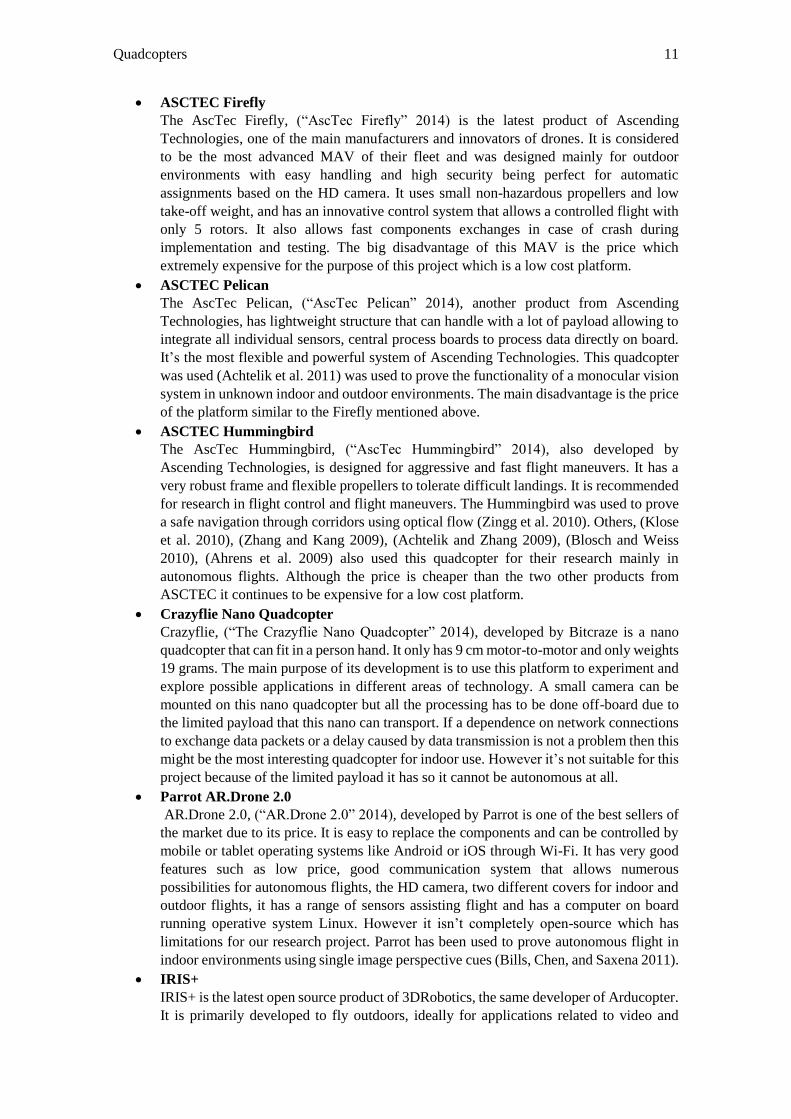
ASCTEC Firefly
The AscTec Firefly, (“AscTec Firefly” 2014) is the latest product of Ascending
Technologies, one of the main manufacturers and innovators of drones. It is considered
to be the most advanced MAV of their fleet and was designed mainly for outdoor
environments with easy handling and high security being perfect for automatic
assignments based on the HD camera. It uses small non-hazardous propellers and low
take-off weight, and has an innovative control system that allows a controlled flight with
only 5 rotors. It also allows fast components exchanges in case of crash during
implementation and testing. The big disadvantage of this MAV is the price which
extremely expensive for the purpose of this project which is a low cost platform.
ASCTEC Pelican
The AscTec Pelican, (“AscTec Pelican” 2014), another product from Ascending
Technologies, has lightweight structure that can handle with a lot of payload allowing to
integrate all individual sensors, central process boards to process data directly on board.
It’s the most flexible and powerful system of Ascending Technologies. This quadcopter
was used (Achtelik et al. 2011) was used to prove the functionality of a monocular vision
system in unknown indoor and outdoor environments. The main disadvantage is the price
of the platform similar to the Firefly mentioned above.
ASCTEC Hummingbird
The AscTec Hummingbird, (“AscTec Hummingbird” 2014), also developed by
Ascending Technologies, is designed for aggressive and fast flight maneuvers. It has a
very robust frame and flexible propellers to tolerate difficult landings. It is recommended
for research in flight control and flight maneuvers. The Hummingbird was used to prove
a safe navigation through corridors using optical flow (Zingg et al. 2010). Others, (Klose
et al. 2010), (Zhang and Kang 2009), (Achtelik and Zhang 2009), (Blosch and Weiss
2010), (Ahrens et al. 2009) also used this quadcopter for their research mainly in
autonomous flights. Although the price is cheaper than the two other products from
ASCTEC it continues to be expensive for a low cost platform.
Crazyflie Nano Quadcopter
Crazyflie, (“The Crazyflie Nano Quadcopter” 2014), developed by Bitcraze is a nano
quadcopter that can fit in a person hand. It only has 9 cm motor-to-motor and only weights
19 grams. The main purpose of its development is to use this platform to experiment and
explore possible applications in different areas of technology. A small camera can be
mounted on this nano quadcopter but all the processing has to be done off-board due to
the limited payload that this nano can transport. If a dependence on network connections
to exchange data packets or a delay caused by data transmission is not a problem then this
might be the most interesting quadcopter for indoor use. However it’s not suitable for this
project because of the limited payload it has so it cannot be autonomous at all.
Parrot AR.Drone 2.0
AR.Drone 2.0, (“AR.Drone 2.0” 2014), developed by Parrot is one of the best sellers of
the market due to its price. It is easy to replace the components and can be controlled by
mobile or tablet operating systems like Android or iOS through Wi-Fi. It has very good
features such as low price, good communication system that allows numerous
possibilities for autonomous flights, the HD camera, two different covers for indoor and
outdoor flights, it has a range of sensors assisting flight and has a computer on board
running operative system Linux. However it isn’t completely open-source which has
limitations for our research project. Parrot has been used to prove autonomous flight in
indoor environments using single image perspective cues (Bills, Chen, and Saxena 2011).
IRIS+
IRIS+ is the latest open source product of 3DRobotics, the same developer of Arducopter.
It is primarily developed to fly outdoors, ideally for applications related to video and
12 State of Art
photos powered by a dead steady camera with two axis gimbal stabilization. It has the
new follow-me mode that is able to follow any GPS android device. It also as the new
autopilot system developed by 3DRobotics and a flight time battery of plus 16 minutes.
Figure 2.3 - Commercial Solutions: (a) - Firefly (b) - Hummingbird (c) - Pelican (d) - Parrot 2.0 (e) - Crazyflie
(f) - Iris
2.2.5 Flight Controllers
In this section some of the most common flight controllers are reviewed. Choosing one it is
truly important because without them it would be impossible to fly. Flight controllers have many
sensors built-in like accelerometers, gyroscopes, magnometer, GPS, barometric, pressure sensors
or airspeed sensors. The main contributors are the gyroscope fused with the accelerometer and
magnometer. While the accelerometers measure linear acceleration, gyros measure a rate rotation
about an axis. The sensor fusion is made by the Inertial Measurement Unit (IMU) in order to
estimate pose of the quadcopter. The IMU reads the data from all those sensors and converts the
quadcopter flight into a stable flight platform by using a Proportional Integral Derivative (PID)
control loop. The PID loop and the tuning are one of the most important things to get a stable
flight. The PID values depend on the type of application it is want to give to the quadcopter: if it
is stable flights or acrobatic flights, if it is to be used indoors or outdoors as the wind is an
important external factor that has consequences on the stability of the quadcopter. Each flight
controller has a characteristic of its own that makes them unique: there flight controllers
specialized for autonomous flying, for flying indoors, for flying outdoors, for acrobatic sport
flights, for stable flights and others that try to be good overall. The most currently interesting
flight controllers available are:
Pixhawk
Pixhawk developed by 3DRobotics, is the substitute of Ardupilot Mega and it is specially
designed for fully autonomous flight. The firmware is all open source so it is possible to
add new features and keep the platform growing as it has an increased memory when
compared to its predecessor. The Pixhawk features an advanced 32 bit processor and
sensor technology delivering flexibility and reliability for controlling any autonomous
vehicle. It uses the software Mission Planner where it is possible to prepare missions with
designated waypoints. The price around 200 euros is certainly expensive in the flight
controller world but this board comes with a lot of built-in features making it a fair price.
The prime feature is the ability to fly autonomously as long the GPS signal is available.
Solutions for Autonomy 13
It also offers a big number of ports to connect external hardware to it, allowing the
possibility to improve flight features because more sensors can be added easily. It also
offers several flight modes: acrobatic, stable, loiter, autonomous and others. This was the
board selected for this dissertation and it will be reviewed closely in chapter 3.
Naze32
Naze32 is an amazing autopilot board that is incredibly small (36x36mm) and has a 32
bit processor built in with a 3 axis magnometer, 3 axis gyroscope plus accelerometer. It
is designed to be a hybrid that can go both indoor and outdoor without reducing the
performance. The low cost price around 50 euros, completely open source, makes it one
of the most interesting flight controllers in the market. This board however is designed
for hobby flights like fun fliers or acrobatics.
KKmulticopter
The KKmulticopter developed by Robert R. Bakke, is famous by the 3 gyroscopes, 3
accelerometers, a microcontroller dedicated to handling sensor output, easy to set up and
a low cost price. The disadvantage is that the firmware is written in assembly what limits
the number of developers and the growth of the platform.
DJI Naza-MV 2
This board developed by DJI, is made for users that want to make videos or shoot photos
and not taking a special care about flying the drone. It has amazing features like intelligent
orientation control or return home mode. However the firmware can’t be modified so
future expandability or the implementation of extra features is not possible reducing the
attractiveness of the board.
OpenPilot CC3D
This board developed by OpenPilot, is ideal for high speed maneuvers enthusiasts. The
firmware is completely open source and it can be used with the monitor Ground Control
Station (GCS).
2.3 Solutions for autonomy
In this section are reviewed approaches to calculate location and mapping of the surrounding
environment. It will also be object of consideration object and people detection and tracking
methods.
2.3.1 SLAM
This project focus is to monitor and help elderly or disabled people with their tasks at home,
so it’s mandatory to the quadcopter to know his exact absolute location in the environment. As
mentioned in the section above, while most outdoor MAVs have reached a very satisfying
performance when it comes to autonomy, most indoor environments don’t have access to external
positioning points like GPS signal. A solution to this problem is a technique called Simultaneous
Localization and Mapping (SLAM) that generates a map (without prior knowledge of the
environment) or updates it (with prior knowledge) while at the same time calculates the position
on that map. Most of the SLAM algorithms developed for ground or underwater vehicles show
good results but for MAVs, SLAM is still a challenge due to their fast dynamics, limited
computation and payload. Data provided by the sensors must have high quality to the system
perform accurately. This data usually represents the distance to relevant objects like walls and
includes details about boundaries. How faster the frequency of the details is updated, more
accurate and better performance is achieved. However there are problems that need to be tackled
such as limited lightning, lack of features or repetitive structures. Building accurate models of
14 State of Art
indoor environments is crucial not only for robotics but also for gaming, augmented reality
applications and is currently an extensive field of research. This section reviews briefly the theory
behind SLAM, the most common hardware sensing devices to capture data of the environment,
the algorithms that use the captured data to update a map and the location in the environment and
also a review of several examples about SLAM applied to quadcopters. One of the most important
things is to choose the range measurement device. There are 3 sensors which are commonly used
by researchers to sense the environment: laser scanners, sonar sensors and vision. Laser scanners
are by far the most used device by the community due to the accuracy of the data. They can have
ranges up to 8 meters and they are very fast to update the data as they can be queried at 11 Hz via
serial port. However, laser scanners don’t achieve accurate data in all types of surfaces as they
have problems with glass for example. Plus, the market price is about 5000 euros which is a lot if
the project is low cost. Sonar sensor was the most used sensor for SLAM before laser scanners.
They are cheaper when compared to laser scanners but the accuracy of readings is a lot worse
than the lasers. Laser scanners easily have a straight line of measurement with a width of 0.25
degrees while sonar have beams up to 30 degrees in width. Third option is vision where there has
been an extensive research over the last decade. It’s computationally expensive but with recent
advances in creating more powerful and small processors, vision started to be an option for SLAM
applications. It’s an intuitive option to try to offer robots the vision that humans have of the
environment. It’s important to notice however that light is a limitation for vision implementations.
If the room is completely dark, then it will be almost impossible to get readings.
SLAM consists in multiple parts: landmark extraction, data association, state estimation, state
update and landmark update. There are several ways to solve each part. The purpose of SLAM is
to use the environment sensed data to update the position of the robot. The objective is to extract
features of the environment with the sensing device and observe when the robot moves around.
Based on these extracted features the robot will have to make a guess of where he is. The most
common approaches are statistical approaches like the Kalman filters (EFK) or particle filters
(Monte Carlo Localization). The extracted features are often called as landmarks. A landmark
should be easily re-observable, distinguishable from each other, should be stationary and the
surrounding environment should have plenty of landmarks so that the robot doesn’t lose a lot of
time to find the landmark while errors from the IMU are escalating. There are several algorithms
for landmark extraction like: RANSAC (extract lines from laser scanner) or Viola and Jones
(vision). After the extraction of the landmarks the robot attempts to associate these landmarks to
observations of landmarks previously seen. This step is usually called data association. New
landmarks that were not previously seen, are saved as new observations so they can be observed
later. If good landmarks are defined then data association should be easy. If bad landmarks are
defined then it’s possible that wrong associations arise. If a wrong association is made it could be
disastrous because it would cause an error on the robot position. Data association algorithm
normally consists in a data base to store the landmarks previously seen. A landmark is only stored
after being viewed several times (to diminish the possibility of extracting a wrong landmark),
nearest neighbor approach is then used to associate a landmark with the nearest landmark in the
database using the Euclidean distance. After landmark extraction and data association steps, EKF
(Extended Kalman Filter) or MCL (Monte Carlo Localization) are applied. It’s important to notice
that both EKF and MCL start by an initial guess of data provided by the IMU. The goal of this
data is to provide an approximate position of where the robot is, that then is corrected by the
sensed data of the environment. Both approaches are briefly reviewed in the following lines. The
EKF is used to estimate the state (position) of the robot using the IMU data and landmark
observations. It starts with an update of the current state estimate using the IMU data, it uses the
IMU data to compute the rotation from the initial coordinates to new coordinates. Then updates
the estimate state from re-observing the landmarks and finally adds new landmarks to the current
state. MCL is based in a particle filter to represent the distribution of likely states, with each
particle representing a possible state, a hypothesis of where the robot is. Typically starts with a
Solutions for Autonomy 15
random distribution of particles, in the beginning the vehicle doesn’t know where he is at and
assumes it is equally likely to be in any point of the space. If the robot moves, it shifts the particles
to predict the new state after the movement. When the robots senses something the particles are
resampled based on a recursive Bayesian estimation, evaluate how well the sensed data correlates
with the predicted state. The particles should converge towards the actual position of the robot.
After a brief description of SLAM theory, a review of projects that built autonomous
quadcopters for navigation in indoor environments follows. IMU data fused with a monocular
camera for 3D position estimation was used in recent works (Achtelik et al. 2011). The position
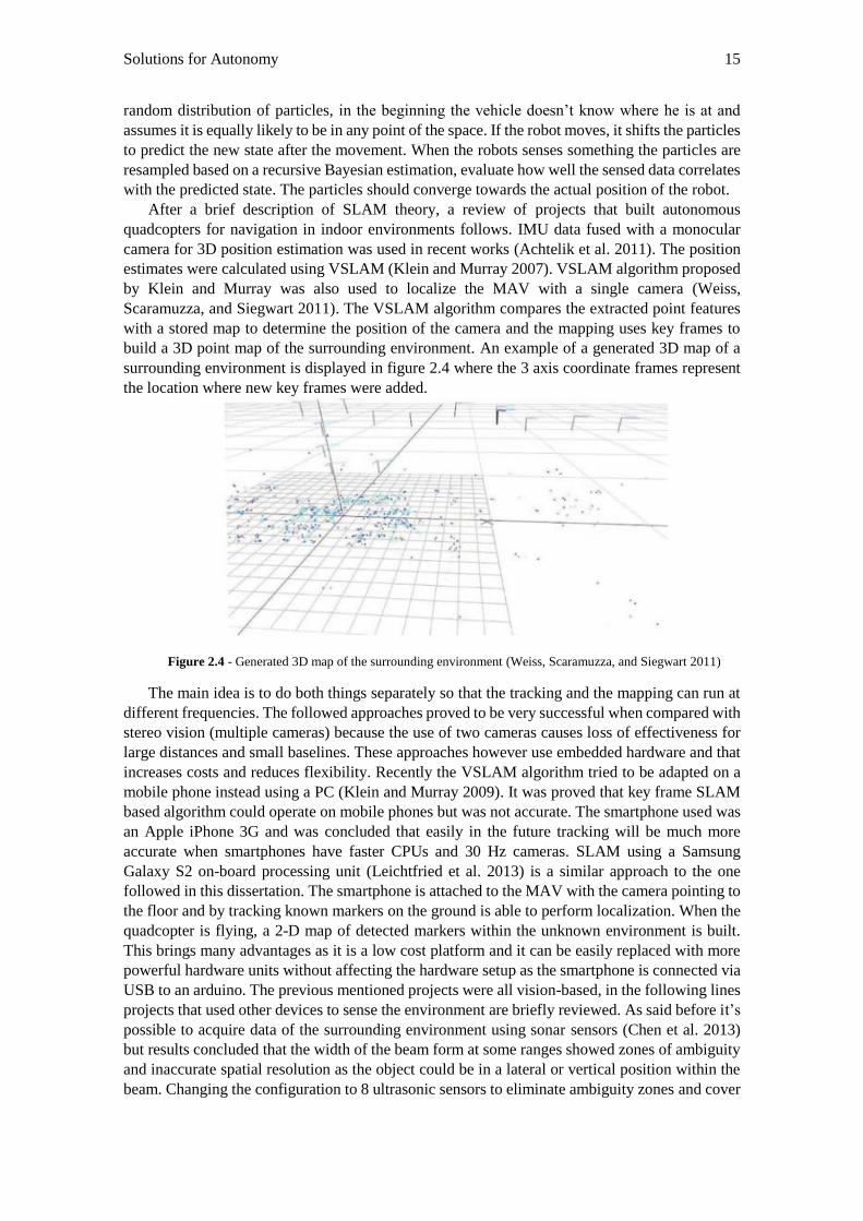
estimates were calculated using VSLAM (Klein and Murray 2007). VSLAM algorithm proposed
by Klein and Murray was also used to localize the MAV with a single camera (Weiss,
Scaramuzza, and Siegwart 2011). The VSLAM algorithm compares the extracted point features
with a stored map to determine the position of the camera and the mapping uses key frames to
build a 3D point map of the surrounding environment. An example of a generated 3D map of a
surrounding environment is displayed in figure 2.4 where the 3 axis coordinate frames represent
the location where new key frames were added.
Figure 2.4 - Generated 3D map of the surrounding environment (Weiss, Scaramuzza, and Siegwart 2011)
The main idea is to do both things separately so that the tracking and the mapping can run at
different frequencies. The followed approaches proved to be very successful when compared with
stereo vision (multiple cameras) because the use of two cameras causes loss of effectiveness for
large distances and small baselines. These approaches however use embedded hardware and that
increases costs and reduces flexibility. Recently the VSLAM algorithm tried to be adapted on a
mobile phone instead using a PC (Klein and Murray 2009). It was proved that key frame SLAM
based algorithm could operate on mobile phones but was not accurate. The smartphone used was
an Apple iPhone 3G and was concluded that easily in the future tracking will be much more
accurate when smartphones have faster CPUs and 30 Hz cameras. SLAM using a Samsung
Galaxy S2 on-board processing unit (Leichtfried et al. 2013) is a similar approach to the one
followed in this dissertation. The smartphone is attached to the MAV with the camera pointing to
the floor and by tracking known markers on the ground is able to perform localization. When the
quadcopter is flying, a 2-D map of detected markers within the unknown environment is built.
This brings many advantages as it is a low cost platform and it can be easily replaced with more
powerful hardware units without affecting the hardware setup as the smartphone is connected via
USB to an arduino. The previous mentioned projects were all vision-based, in the following lines
projects that used other devices to sense the environment are briefly reviewed. As said before it’s
possible to acquire data of the surrounding environment using sonar sensors (Chen et al. 2013)
but results concluded that the width of the beam form at some ranges showed zones of ambiguity
and inaccurate spatial resolution as the object could be in a lateral or vertical position within the
beam. Changing the configuration to 8 ultrasonic sensors to eliminate ambiguity zones and cover
16 State of Art
all the angles was tried but the time to record the distance to all objects was in order of 1 second
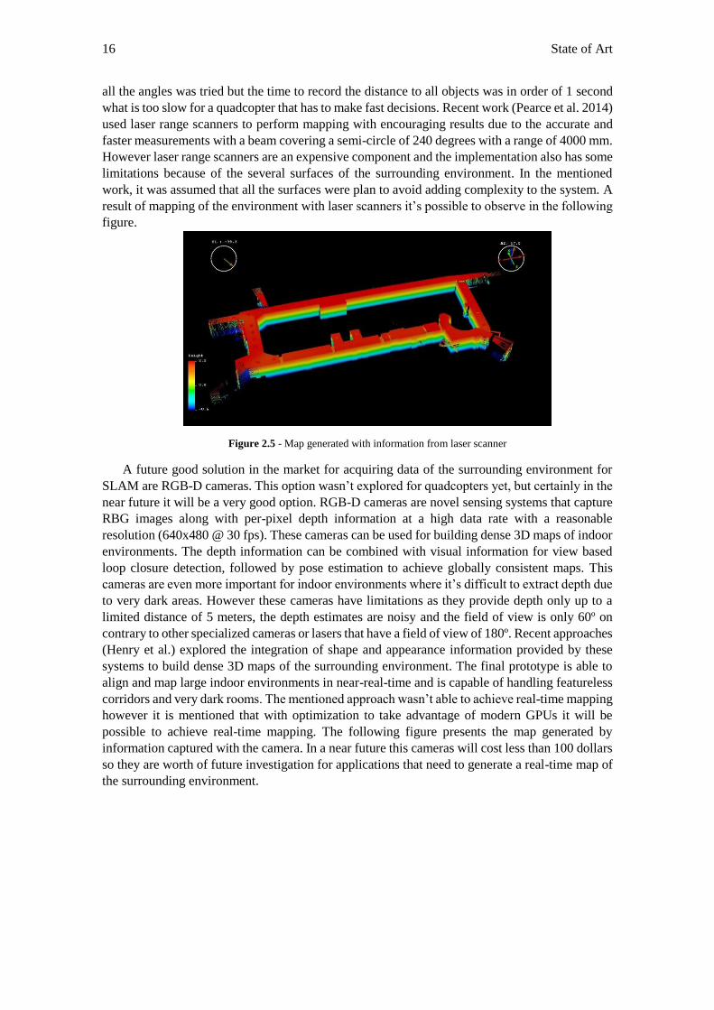
what is too slow for a quadcopter that has to make fast decisions. Recent work (Pearce et al. 2014)
used laser range scanners to perform mapping with encouraging results due to the accurate and
faster measurements with a beam covering a semi-circle of 240 degrees with a range of 4000 mm.
However laser range scanners are an expensive component and the implementation also has some
limitations because of the several surfaces of the surrounding environment. In the mentioned
work, it was assumed that all the surfaces were plan to avoid adding complexity to the system. A
result of mapping of the environment with laser scanners it’s possible to observe in the following
figure.
Figure 2.5 - Map generated with information from laser scanner
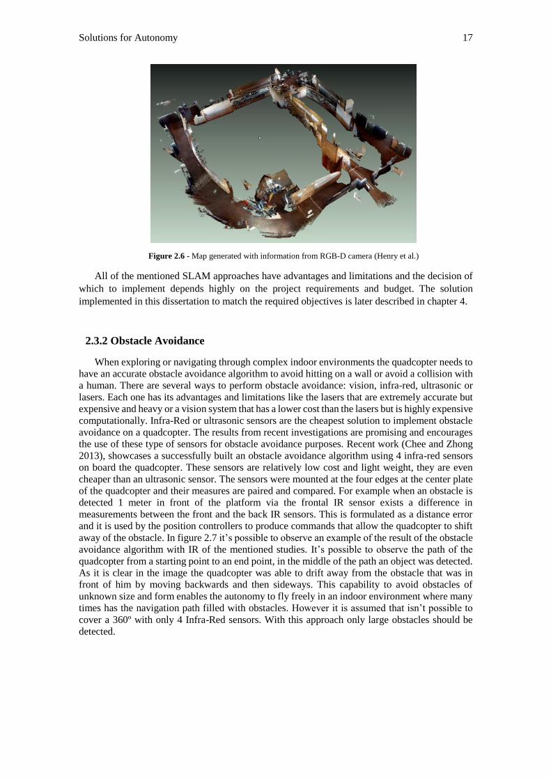
A future good solution in the market for acquiring data of the surrounding environment for
SLAM are RGB-D cameras. This option wasn’t explored for quadcopters yet, but certainly in the
near future it will be a very good option. RGB-D cameras are novel sensing systems that capture
RBG images along with per-pixel depth information at a high data rate with a reasonable
resolution (640x480 @ 30 fps). These cameras can be used for building dense 3D maps of indoor
environments. The depth information can be combined with visual information for view based
loop closure detection, followed by pose estimation to achieve globally consistent maps. This
cameras are even more important for indoor environments where it’s difficult to extract depth due
to very dark areas. However these cameras have limitations as they provide depth only up to a
limited distance of 5 meters, the depth estimates are noisy and the field of view is only 60º on
contrary to other specialized cameras or lasers that have a field of view of 180º. Recent approaches
(Henry et al.) explored the integration of shape and appearance information provided by these
systems to build dense 3D maps of the surrounding environment. The final prototype is able to
align and map large indoor environments in near-real-time and is capable of handling featureless
corridors and very dark rooms. The mentioned approach wasn’t able to achieve real-time mapping
however it is mentioned that with optimization to take advantage of modern GPUs it will be
possible to achieve real-time mapping. The following figure presents the map generated by
information captured with the camera. In a near future this cameras will cost less than 100 dollars
so they are worth of future investigation for applications that need to generate a real-time map of
the surrounding environment.
Solutions for Autonomy 17
Figure 2.6 - Map generated with information from RGB-D camera (Henry et al.)
All of the mentioned SLAM approaches have advantages and limitations and the decision of
which to implement depends highly on the project requirements and budget. The solution
implemented in this dissertation to match the required objectives is later described in chapter 4.
2.3.2 Obstacle Avoidance
When exploring or navigating through complex indoor environments the quadcopter needs to
have an accurate obstacle avoidance algorithm to avoid hitting on a wall or avoid a collision with
a human. There are several ways to perform obstacle avoidance: vision, infra-red, ultrasonic or
lasers. Each one has its advantages and limitations like the lasers that are extremely accurate but
expensive and heavy or a vision system that has a lower cost than the lasers but is highly expensive
computationally. Infra-Red or ultrasonic sensors are the cheapest solution to implement obstacle
avoidance on a quadcopter. The results from recent investigations are promising and encourages
the use of these type of sensors for obstacle avoidance purposes. Recent work (Chee and Zhong
2013), showcases a successfully built an obstacle avoidance algorithm using 4 infra-red sensors
on board the quadcopter. These sensors are relatively low cost and light weight, they are even
cheaper than an ultrasonic sensor. The sensors were mounted at the four edges at the center plate
of the quadcopter and their measures are paired and compared. For example when an obstacle is
detected 1 meter in front of the platform via the frontal IR sensor exists a difference in
measurements between the front and the back IR sensors. This is formulated as a distance error
and it is used by the position controllers to produce commands that allow the quadcopter to shift
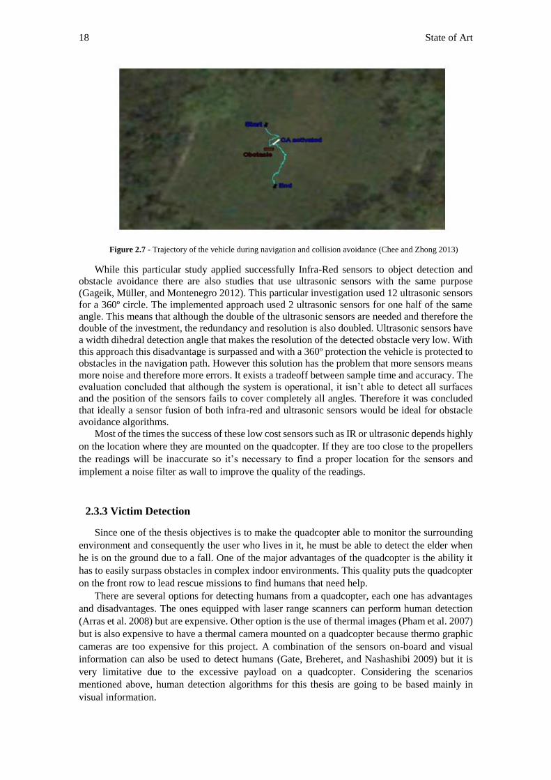
away of the obstacle. In figure 2.7 it’s possible to observe an example of the result of the obstacle
avoidance algorithm with IR of the mentioned studies. It’s possible to observe the path of the
quadcopter from a starting point to an end point, in the middle of the path an object was detected.
As it is clear in the image the quadcopter was able to drift away from the obstacle that was in
front of him by moving backwards and then sideways. This capability to avoid obstacles of
unknown size and form enables the autonomy to fly freely in an indoor environment where many
times has the navigation path filled with obstacles. However it is assumed that isn’t possible to
cover a 360º with only 4 Infra-Red sensors. With this approach only large obstacles should be
detected.
18 State of Art
Figure 2.7 - Trajectory of the vehicle during navigation and collision avoidance (Chee and Zhong 2013)
While this particular study applied successfully Infra-Red sensors to object detection and
obstacle avoidance there are also studies that use ultrasonic sensors with the same purpose
(Gageik, Müller, and Montenegro 2012). This particular investigation used 12 ultrasonic sensors
for a 360º circle. The implemented approach used 2 ultrasonic sensors for one half of the same
angle. This means that although the double of the ultrasonic sensors are needed and therefore the
double of the investment, the redundancy and resolution is also doubled. Ultrasonic sensors have
a width dihedral detection angle that makes the resolution of the detected obstacle very low. With
this approach this disadvantage is surpassed and with a 360º protection the vehicle is protected to
obstacles in the navigation path. However this solution has the problem that more sensors means
more noise and therefore more errors. It exists a tradeoff between sample time and accuracy. The
evaluation concluded that although the system is operational, it isn’t able to detect all surfaces
and the position of the sensors fails to cover completely all angles. Therefore it was concluded
that ideally a sensor fusion of both infra-red and ultrasonic sensors would be ideal for obstacle
avoidance algorithms.
Most of the times the success of these low cost sensors such as IR or ultrasonic depends highly
on the location where they are mounted on the quadcopter. If they are too close to the propellers
the readings will be inaccurate so it’s necessary to find a proper location for the sensors and
implement a noise filter as wall to improve the quality of the readings.
2.3.3 Victim Detection
Since one of the thesis objectives is to make the quadcopter able to monitor the surrounding
environment and consequently the user who lives in it, he must be able to detect the elder when
he is on the ground due to a fall. One of the major advantages of the quadcopter is the ability it
has to easily surpass obstacles in complex indoor environments. This quality puts the quadcopter
on the front row to lead rescue missions to find humans that need help.
There are several options for detecting humans from a quadcopter, each one has advantages
and disadvantages. The ones equipped with laser range scanners can perform human detection
(Arras et al. 2008) but are expensive. Other option is the use of thermal images (Pham et al. 2007)
but is also expensive to have a thermal camera mounted on a quadcopter because thermo graphic
cameras are too expensive for this project. A combination of the sensors on-board and visual
information can also be used to detect humans (Gate, Breheret, and Nashashibi 2009) but it is
very limitative due to the excessive payload on a quadcopter. Considering the scenarios
mentioned above, human detection algorithms for this thesis are going to be based mainly in
visual information.
Solutions for Autonomy 19
Human detection in camera images has been a field of major interest and investment due to
its advantages for surveillance purposes. A lot of progress has been made in recent years mainly
in pedestrian detection with histograms of orient gradient (HOG), (Dalal and Triggs) as a leader
in performing methods. However victim detection from a camera on-board of a quadcopter faces
other challenges than the ones that a steady camera for surveillance has to tackle. The victim most
of the times isn’t completely visible because the body is partially occluded by an object like a
table and a human body when lied on the ground can have an immense variety of poses. Other
problem that needs to be tackled is the motion of the quadcopter since it cannot stop on the air the
camera will not be steady pointing at a specific location.
Commonly two methods are addressed to perform human detection from video imagery:
monolithic methods and part based models. As mentioned before, HOG descriptor is one of the
most popular methods for human detection. This algorithm is based on counting the number of
occurrences of gradient orientation in portions of the image, the gradients are calculated and
normalized in a local and overlapping block and concatenated to a single descriptor of a detection
window. The major advantages of this algorithms compared to other descriptors are since this
descriptor operates in local blocks it has invariance to geometric and photometric transformations.
Strong normalization, spatial and orientation sampling allows to ignore the body movement of
pedestrians as long they maintain upright position. The problem of this descriptor is that doesn’t
achieve high performance when as to deal with partial occlusion of body parts (Andriluka et al.
2010) as it possible to see in figure 2.8. Part based models are based in using several part of the
image separately. One of the most popular methods is the discriminatively part based model
(Felzenszwalb, McAllester, and Ramanan 2008), it is built in pictorial structures framework.
These structures are objects by a collection of parts arranged in a deformable configuration. Each
part captures local appearance properties of an object, while the deformable configuration is
characterized by connection of certain pairs of parts. Recent work (Andriluka et al. 2010)
considered that DPM is much more robust when analyzing images taken by a quadcopter for
human detection because it focuses on the division of parts when HOG doesn’t take spatial
variability of the body parts in account.
Figure 2.8 - Victim Detection from a Quadcopter (Andriluka et al. 2010)
2.3.4 Feature Detectors
To help perform SLAM or to detect lost objects using vision, a possibility is to implement a
feature detectors algorithm. In SLAM these feature detectors algorithms are used for landmark
extraction and data association. These algorithms are extremely computational expensive but
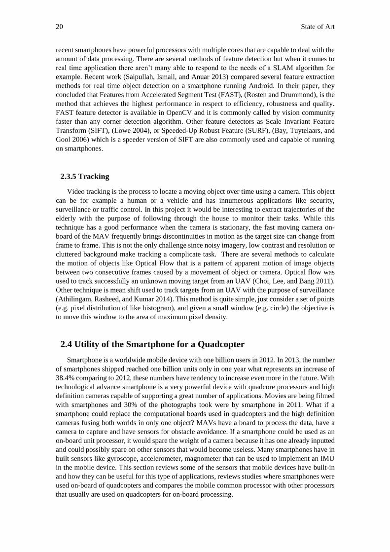
20 State of Art
recent smartphones have powerful processors with multiple cores that are capable to deal with the
amount of data processing. There are several methods of feature detection but when it comes to
real time application there aren’t many able to respond to the needs of a SLAM algorithm for
example. Recent work (Saipullah, Ismail, and Anuar 2013) compared several feature extraction
methods for real time object detection on a smartphone running Android. In their paper, they
concluded that Features from Accelerated Segment Test (FAST), (Rosten and Drummond), is the
method that achieves the highest performance in respect to efficiency, robustness and quality.
FAST feature detector is available in OpenCV and it is commonly called by vision community
faster than any corner detection algorithm. Other feature detectors as Scale Invariant Feature
Transform (SIFT), (Lowe 2004), or Speeded-Up Robust Feature (SURF), (Bay, Tuytelaars, and
Gool 2006) which is a speeder version of SIFT are also commonly used and capable of running
on smartphones.
2.3.5 Tracking
Video tracking is the process to locate a moving object over time using a camera. This object
can be for example a human or a vehicle and has innumerous applications like security,
surveillance or traffic control. In this project it would be interesting to extract trajectories of the
elderly with the purpose of following through the house to monitor their tasks. While this
technique has a good performance when the camera is stationary, the fast moving camera on-
board of the MAV frequently brings discontinuities in motion as the target size can change from
frame to frame. This is not the only challenge since noisy imagery, low contrast and resolution or
cluttered background make tracking a complicate task. There are several methods to calculate
the motion of objects like Optical Flow that is a pattern of apparent motion of image objects
between two consecutive frames caused by a movement of object or camera. Optical flow was
used to track successfully an unknown moving target from an UAV (Choi, Lee, and Bang 2011).
Other technique is mean shift used to track targets from an UAV with the purpose of surveillance
(Athilingam, Rasheed, and Kumar 2014). This method is quite simple, just consider a set of points
(e.g. pixel distribution of like histogram), and given a small window (e.g. circle) the objective is
to move this window to the area of maximum pixel density.
2.4 Utility of the Smartphone for a Quadcopter
Smartphone is a worldwide mobile device with one billion users in 2012. In 2013, the number
of smartphones shipped reached one billion units only in one year what represents an increase of
38.4% comparing to 2012, these numbers have tendency to increase even more in the future. With
technological advance smartphone is a very powerful device with quadcore processors and high
definition cameras capable of supporting a great number of applications. Movies are being filmed
with smartphones and 30% of the photographs took were by smartphone in 2011. What if a
smartphone could replace the computational boards used in quadcopters and the high definition
cameras fusing both worlds in only one object? MAVs have a board to process the data, have a
camera to capture and have sensors for obstacle avoidance. If a smartphone could be used as an
on-board unit processor, it would spare the weight of a camera because it has one already inputted
and could possibly spare on other sensors that would become useless. Many smartphones have in
built sensors like gyroscope, accelerometer, magnometer that can be used to implement an IMU
in the mobile device. This section reviews some of the sensors that mobile devices have built-in
and how they can be useful for this type of applications, reviews studies where smartphones were
used on-board of quadcopters and compares the mobile common processor with other processors
that usually are used on quadcopters for on-board processing.
Utility of a Smartphone for a Quadcopter 21
2.4.1 Smartphone Sensors
Today smartphones usually bring a full set of sensors that can be used for innumerous
applications. There are sensors that measure motion, orientation and several environmental
conditions. For motion sensing exists an accelerometer and a gyroscope, for environmental
measures like pressure, illumination or humidity there are barometers or thermometers and to
measure physical position exists the magnometer. Usually a common smartphone has an
accelerometer, a gyroscope, a magnometer, a barometer and a camera inbuilt. All of these sensors
have errors in their output values. If the smartphone is resting in a surface it’s possible to see that
the rotation or linear acceleration values are not zero. Later in this document it’s demonstrated
how the noise can be reduced to improve sensor accuracy. In this section it will be reviewed what
is the purpose of this sensors and how they can be useful for this dissertation. To start it’s
necessary to introduce the smartphone coordinate system in figure 2.9:
Figure 2.9 - Coordinate System used by Android API (Lawitzki 2012)
When the device it’s held in in its default orientation, the X axis is horizontal and points to
the right, the Y axis is vertical and points up and Z axis points towards outside the screen face. A
brief description of each smartphone sensor follows:
2.4.1.1 Accelerometer
The accelerometer measures the acceleration force in 𝑚 𝑠2⁄ that is applied to a device on all
three physical axis (x, y, z) including gravitational force. It is commonly used to recognize motion
activities. The accelerometer has an error called bias that can be estimated by measuring the long
term average of the accelerometers output when there is no acceleration.
2.4.1.2 Gyroscope
The gyroscope measures the device rate rotation in 𝑟𝑎𝑑 𝑠⁄ around the three physical axis (x,
y, z). It is used to correct the current orientation of the device while it is in motion. Other sensors
like the magnometer have errors caused by the magnetic fields in the surrounding environment or
22 State of Art
the accelerometers whose values are only accurate when the mobile device is stationary. The
gyroscope is also commonly used to get the current orientation of the mobile device. The
gyroscope also has errors like the gyroscope drift. This drift increases linearly over time and is
caused by the integration of rotation values to compute orientation. Thankfully, the errors of these
sensors have different causes and they can complement each other to eliminate a big part of the
errors in their outputs.
2.4.1.3 Magnometer
The magnometer measures the magnetic field sensor in micro Tesla around the physical axis
(x, y, z). It is commonly fused with the accelerometer to find the direction with respect to North.
The error is caused by the magnetic interference in the environment and in the device.
2.4.1.4 Barometer
The barometer is responsible for measuring atmospheric pressure. The barometer can help
predicting a weather forecast or improve altitude measures that come from GPS. Studies used the
barometer for indicating in which floor of the building the user is.
2.4.1.5 Camera
The camera of the mobile device captures visual information of the surrounding environment.
It is a very powerful sensor, useful for innumerous applications related to computer vision. It can
be used to detect objects, detect and recognition of humans, mapping of environments and others.
Smartphone cameras have been improving every year. Nowadays, a common smartphone have
cameras with 8 or 16 MP and have video with a resolution of 2160p @ 30 fps or 1080p @ 60 fps.
Cameras like the other mentioned sensors have noise in the output. Noise imagery can be reduced
using calibration methods provided by the OpenCV library as shown later in this document. This
enables the smartphone to be used to capture real world information instead of using professional
cameras that then have to pass information to a CPU for processing while the smartphone already
has one built in.
All the mentioned sensors are used in this dissertation. The camera is used to capture visual
information, the barometer is used to compute altitude measures, the accelerometer, the gyroscope
and the magnometer information is fused to compute the orientation of the mobile device.
2.4.2 Comparison of a smartphone CPU and other CPUs
Smartphone hardware has suffered a big evolution in the last years and has enabled the mobile
device to be able to contribute to innumerous applications like the one of this dissertation. This
section reviews a common smartphone CPU and compares it with other two CPUs that were used
for processing information on-board of a quadcopter. The smartphone reviewed is Google Nexus
5 that already was used on-board of a quadcopter with positive results.
Google Nexus 5 – This smartphone has a CPU quadcore 2.3 GHz Krait 400 and 2GB of
RAM. It has a body weight of 130g. It was used successfully in a project that developed
an autonomous drone (Pearce et al. 2014). It was responsible for processing all
information on board related to navigation.
The CPUs reviewed will be two ASCTEC processors that were used in the past on-board of
quadcopters to implement autonomy:
Utility of a Smartphone for a Quadcopter 23
ASCTEC Intel Atom Processor - This board, (“AscTec Atomboard” 2014), runs at 1.6
GHz, has 1 GB RAM and weights 90g. This board runs on the quadcopters mentioned
above developed by ASCTEC Technologies. It was used in a successful achievement
towards the goal of autonomous flight based in monocular vision (Achtelik et al. 2011).
Also used in other works (Shen, Michael, and Kumar 2011) as the successful research for
autonomy in buildings with multiple floors. All the computation of these two projects
was made on board, which means Atom is powerful enough to run computer vision
algorithms.
ASCTEC Mastermind Processor - This board, (“AscTec Mastermind” 2014), is based
on IntelCore2Duo processor with 1.86 GHz, has 4 GB RAM and weights 275g. It can be
used in ASCTEC Pelican or Hummingbird. This board offers a tremendous computation
power to run computer vision algorithms.
It is possible to conclude from the above descriptions that the smartphone is completely able
to compete with both of these two boards used in the past for processing information on-board of
a quadcopter. With the plus of also having several sensors on-board that allows sensing the
surrounding environment. This analysis enables the smartphone to be the center of all the
processing on board of the quadcopter, it is perfectly capable to act as the brain of the quadcopter.
2.4.3 Smartphone on-board of Quadcopters
Although the analysis above showed that smartphones are capable to be used on-board of a
quadcopter to acquire information with the sensors and process it, there were only a few projects
that tried to implement a smartphone as a central unit processor on-board of the quadcopter. The
projects that are close to this dissertation are: Flyphone (Erhard, Wenzel, and Zell 2010),
Smartcopter (Leichtfried et al. 2013) and a quadcopter developed by MITRE (Chen et al. 2013)
that then suffered an evolution a year later (Pearce et al. 2014). These are 4 research projects
which presented a flexible, intelligent, low weight platform for autonomous navigation and are
the most comparable approaches to the one followed in this project.
Flyphone used a Nokia95 equipped with a CPU of 332 MHz Dual Arm to run the computer
vision algorithms. The camera of the mobile phone had 5 MP and was used to capture visual data
for localization methods. The quadcopter computes the location comparing current images with
images in the data base. The comparison is made by extracting features from the images. The
feature extraction algorithm used was WGOH and the feature comparison measure was the
Euclidean distance. However the tests were performed outdoor in a large area and the positional
errors were around 10 m. This error is tolerable in outdoor applications but in indoor environments
it’s not possible to fly with this error. This system also uses a GPS valid value for the exploration
phase which is not possible in indoor environments. After the exploration phase the system does
not depend on GPS anymore. The localization process takes around 640 ms which also too long
and needs to be accelerated.
Smartcopter used a Samsung Galaxy S2 as on-board processing unit equipped with a CPU of
1.2 GHz dual core Cortex and an 8 MP camera. The smartphone was attached to the bottom of
the UAV with the camera targeting the ground. By tracking known markers on the ground the
quadcopter was able to perform SLAM on the environment. This system had better results when
compared to Flyphone, since the location process takes only 25 ms with a system where all the
entire setup excluding the smartphone costs only 380 euros which means that this project used a
low cost approach. This project influenced the approach followed in this dissertation as it possible
to observe in chapter 3.
MITRE used a Samsung Galaxy III equipped with a CPU of 1.4 GHz quadcore Cortex and
camera of 8 MP as the brain of the system, responsible for the navigation and mission controlling.
This project used ultrasonic sensors to map the environment and Monte Carlo algorithm to
24 State of Art
perform location but the results from the ultrasonic sensors were very unsatisfying since the
computed maps were very rudimentary. It’s also necessary that when using ultrasonic sensors,
the quadcopter is fully oriented so the ultrasonic are perpendicular to the obstacles to be detected.
The use of ultrasonic sensors to map the environment had very poor results that didn’t allow to
use the Monte Carlo algorithm. The project developed my MITRE was recently updated (Pearce
et al. 2014) and the Samsung Galaxy was switched to a more powerful Nexus 5 that has a quadcore
running at 2.3 GHz with a camera of 8 MP. The ultrasonic sensors changed to a more powerful
laser range finder what resulted in a better definition of the computed mapping of the environment
what was expect full since ultrasonic sensors cost around 30 euros while laser scanners can cost
5000 euros.
These 4 projects used successfully a smartphone as an on-board processing unit for SLAM of
the surrounding indoor environment. Of course all the mentioned projects have other limitations
but these are related with the approaches and sensors used to perform SLAM and not with the
smartphone that proved that can be used on-board of a quadcopter for processing data from other
sensors on-board and data coming from its camera. The smartphone we propose for our
development is described in chapter 3, in the system specification section.
2.5 Summary
This chapter describes a review of the literature considered more relevant for this project.
First a summary on robotics applied for AAL allows to conclude that there are a small number of
quadcopters or flying robots applied to AAL scenarios mainly because of questions related to
security and the lack of robustness in quadcopter autonomous systems. The challenges that
quadcopters face when compared to ground robots and their minimum requirements are briefly
resumed. The advantages quadcopters offer in indoor environments such as high mobility,
capability of flying through doors, don’t have to deal with stairs which makes it available to for
multiple floors makes this project very promising and provides courage to overcome challenges.
When creating a quadcopter able to accomplish some use cases related to AAL in indoor
environments, there are techniques that have to be implemented such as SLAM, obstacle
avoidance, object or human detection and tracking. For each one of these techniques, is presented
a summary of the most interesting approaches developed by researchers in this field. Last section
reviews how smartphones can be useful for this dissertation, briefly reviews the sensors that are
built in, compares the CPU with the CPU of other boards that were successfully used for SLAM
purposes and reviews 4 approaches that prove successfully the use smartphones as a central
processing unit on a quadcopter like the way it is proposed in this project.
25
Chapter 3
System Specification
To create a system able to respond to AAL scenarios it is necessary to develop a system
capable of performing autonomous flight in GPS denied environments with obstacle avoidance
algorithms only with on-board equipment without the help of external hardware on the ground or
Wi-Fi communications. This chapter provides a detailed overview of the solutions considered to
achieve autonomous flight, a description of the implemented solution, the project architecture
with a description and features of all the components used to reach the designed solution.
3.1 Overview of Considered Solutions
The project final main goal is to develop an indoor autonomous quadcopter capable of
responding to AAL scenarios requirements. The project started with a previous thesis whose main
objective was to develop a user controllable system: a quadcopter controlled by an Android device
in the user’s hands while exchanging live telemetry data via Wi-Fi. A live video feed from the
quadcopter camera was showing on the smartphone allowing the user to have the perception of
the environment as if he was on the quadcopter. This is commonly addressed as FPV (First Person
View) flying. With this system the user can maneuver the quadcopter indoors and make
surveillance of the environment with the help of a Go Pro camera attached to the quadcopter.
However the applications of the system were always limited to flying for fun or to fulfill a hobby
since the user needs to be with his hands on the mobile device controlling the quadcopter. Also
the exchanging of information (flight commands, telemetry data, video feed) between the
quadcopter and the mobile device relied on Wi-Fi communication and was always dependent of
a network signal. So the next proposed step was to develop a platform that would make possible
the planning of autonomous flights missions in indoor environments without user controllable
inputs or Wi-Fi signal dependency. In order to do achieve this objective it’s necessary to
implement an indoor location system to substitute the absence of the GPS signal and use the
mobile device inside the quadcopter to act as a brain that makes decisions related to navigation
and eye that captures visual information. With the ability of flying in indoor environments
autonomously, the quadcopter would become useful for innumerous applications related to
surveillance and monitorization of complex environments.
To achieve autonomous flight without GPS signal it’s necessary to implement a robust, stable
and accurate system that calculates live pose estimates of the quadcopter in the environment.
26 System Specification
Without accurate sensor data to couple with the IMU sensors, pose estimation errors grow very
rapidly due to the noise of accelerometers and gyroscopes in the controller board. As result of
those errors, the quadcopter loses perception from where he is in the environment what leads to
an unstable flight and most of the times to crashes.
In chapter 2, several methods to implement SLAM were presented. It was necessary to narrow
down all the available possibilities in a way that the final solution meted the project requirements
and budget. The final solution must be efficient, innovative, accurate, use only on-board
equipment for data processing without a ground station and possible to implement in the project
life time (6 months). If possible, meet the mentioned requirements with the lowest budget
possible. The reviewed methods used laser range finders, sonar sensors, monocular or stereo
vision to map the environment and calculate the absolute pose estimation. Every option mentioned
above was considered but at some point, all had more implementation problems when compared
to the followed approach. These are the following reasons why each pose estimation method
mentioned above was excluded:
Laser range finders provide very accurate and fast information for pose estimation. In
previous studies (Shen, Michael, and Kumar 2011), mapped an entire multi floor building
in real-time with a laser retrofitted by mirrors. But laser range finders are very expensive,
the price range can go between 1000 to 5000 euros depending on the detectable range and
the size of the scanned area. Lasers also have implementation problems since the
algorithms to estimate position can become very complex because of the several types of
surfaces that exist in a house. A possible solution would be to assume that every target the
laser aims is a planer surface however that approach adds a considerable amount of error.
Also the laser doesn’t react well to all types of surface. For example the output values if
the surface is glass are very inaccurate. The price, the complexity of the implementation
without making assumptions led to the exclusion of the method. In a near future laser
range finders price will certainly go down, there are already low cost imitations but the
main idea of this dissertation is to make use of the camera of the mobile device to spare
resources and by consequence reduce the vertical weight of the quadcopter.
Ultrasonic sensors also allow to do a map of the area but the final results are very poor
(Chen et al. 2013). The map was so rudimentary that MCL couldn’t be used to perform
localization. Although a very low-cost solution since each sonar costs around 35 euros (to
cover a 360º area would be necessary between 8 and 12), there several problems as
requiring the quadcopter to be fully oriented so that the sonar sensors are perpendicular
to obstacles (walls). The low rate of data provided by sonar sensors is also a problem to
this type of application. The final results of the mentioned studies were very poor as the
final map was very primitive led to the exclusion of this method.
Stereo vision methods were also explored by the research community however it was
proved in the past that stereo vision loses effectiveness when extracting features at a long
distance (Achtelik and Zhang 2009).
RGB-D cameras allow to generate a map of the surrounding environment. However it’s
necessary a large amount of optimization of the currently used algorithms to be able to
suit for this project needs as the mapping is achieved near real-time and not real time
(Henry et al.). In a near future, after some more research and when the price is
considerably lower, RGB-D cameras will certainly be an option due to the rich
information they can capture even in darker rooms or featureless corridors.
Monocular camera fused with IMU data is also a common approach for pose estimates.
Researchers (Achtelik et al. 2011) demonstrated 3D pose estimation without the use of a
pre-conditioned environment. This was the most interesting approach of all the five
explored as it allows to use the camera of the mobile device fused with the data of the
controller board of the quadcopter. The quadcopter was successfully stabilized based on
vision data at the rate of 10Hz fused with IMU data at a rate of 1 KHz. While this approach
Overview of considered solutions 27
achieved excellent results the resources used were completely different from the ones
available for this thesis. The quadcopter used was a commercial hardware platform from
Ascending Technologies with a very powerful on-board processor. These platforms are
quite expensive, they can cost around 3000 euros and the flexibility of the platform is very
poor when compared to the open-source Arducopter. Although it would be possible that
the mobile device had computational resources to handle the algorithms, the noise
imagery of the mobile device camera when compared to a professional camera would be
very difficult to handle as the vision algorithm rely heavily on the extraction of 300
hundred features per frame.
The idea proposed by (Achtelik et al. 2011) was very difficult to follow in this dissertation
for the reasons already mentioned. However the article inspired the solution proposed in this
dissertation. The solution proposed by (Leichtfried et al. 2013) also assumed relevance to this
dissertation because it studied the possibility of using a pre-conditioned environment with
artificial markers for pose estimation. This is important because it helps to relief the computational
effort of the mobile device. The tracking of artificial markers with the mobile device knowing the
location of each marker allows to calculate the absolute position of the quadcopter in the
environment. The use of QR codes to implement a guide route has already been used in the past
to help the navigation of a ground vehicle (Suriyon, Keisuke, and Choompol 2011). The system
extracts the coordinates and detects the angle of the QR code to detect if it is running in the right
direction. If the angle of the code is 0 it means that the robot is running on the right direction, if
it is different of 0 the system adjusts the direction with negative or positive value to correct the
running direction. The final results were encouraging, the maximum deviation gap from the ideal
route guide was 6 cm. This proves the effectiveness of the system when applied to a ground robot.
It was also a solution applied to ground robots in a warehouse where their task is to deliver
shipping to workers (“Kiva Robots Use QR Codes to Sense Their Location” 2015). Although a
solution tested for ground robots, it was never applied for flight vehicles so it is an innovative
solution.
The Pixhawk, the selected flight controller for this project, has an EKF implemented in its
firmware to estimate position, angular velocity and angular orientation of a flight robot. The EKF
is implemented because IMU sensors like the gyroscope and the accelerometer cause errors in the
angles, position and velocity estimated. If these errors aren’t corrected by the use of another signal
like GPS they will continue to grow making impossible to fly. A detailed explanation of how the
EKF implemented in the Pixhawk works with the theory and a brief overview of the mathematics
involved follows: The Kalman Filter is an optimal estimate for linear models with additive
independent white noise in the transition and measurement systems. However in engineering most
systems are non-linear so it’s necessary other approach for estimation. This led to the development
of the EKF. The EKF algorithm has two main steps: predict states described in equations 3.3, 3.4
and update states described in equations 3.7 and 3.8. These are the equations used for prediction
and update states for correction (“Extended Kalman Filter Pixhawk ” 2015):
State transition and observation models aren’t linear functions but differentiable
functions where 𝑥𝑘 is the state vector, 𝑧𝑘 is the measurement vector, 𝑤𝑘 and 𝑣𝑘 are
process and observation noise vectors which are both zero mean multivariate Gaussian
noises with covariance matrices 𝑄𝑘 and 𝑅𝑘:
𝑥𝑘 = 𝑓 (𝑥𝑘−1, 𝑤𝑘−1) 3.1
𝑧𝑘 = ℎ (𝑥𝑘 , 𝑣𝑘) 3.2
Predict state estimate where 𝑥 represents the state vector with neglected process noise:
�̂�𝑘|𝑘−1 = 𝑓 (�̂�𝑘−1|𝑘−1, 0) 3.3
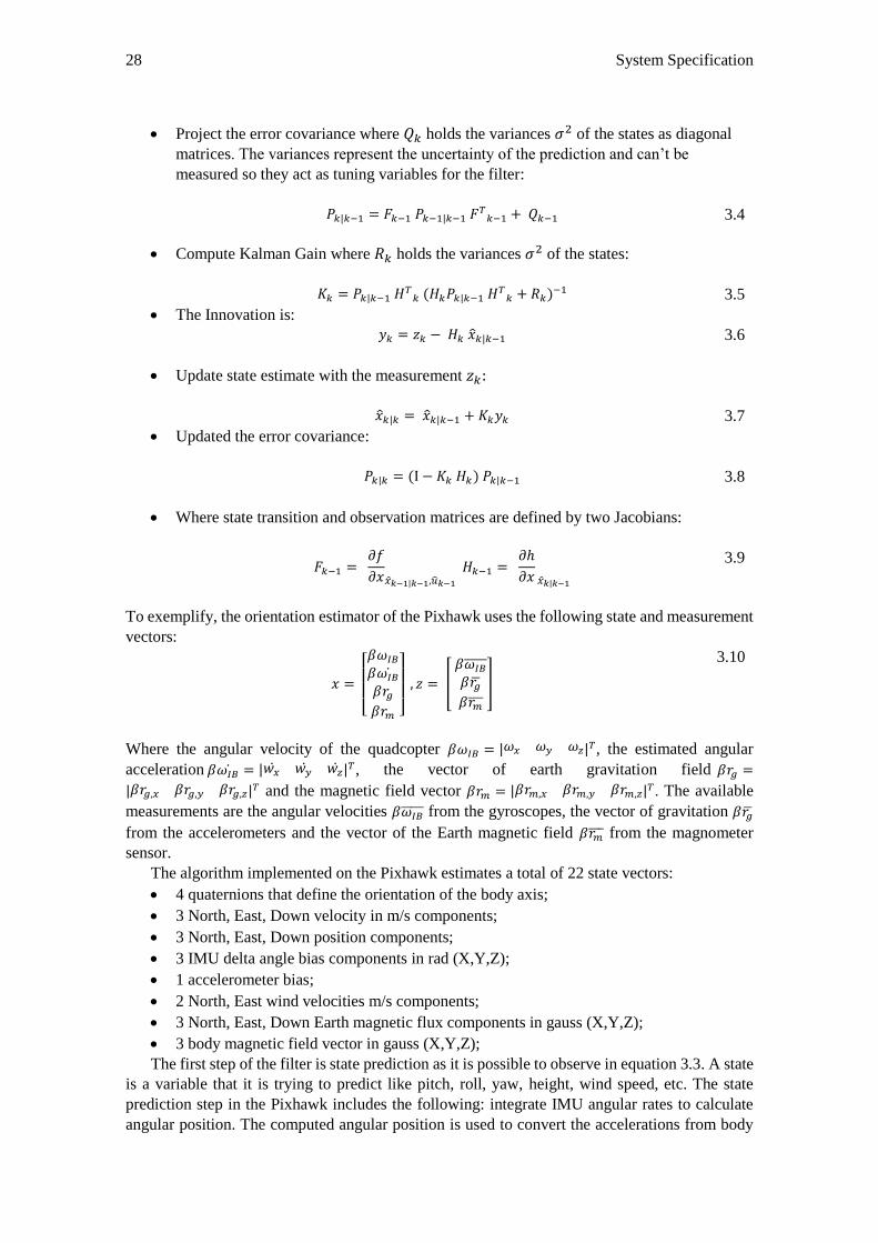
28 System Specification
Project the error covariance where 𝑄𝑘 holds the variances 𝜎2 of the states as diagonal
matrices. The variances represent the uncertainty of the prediction and can’t be
measured so they act as tuning variables for the filter:
𝑃𝑘|𝑘−1 = 𝐹𝑘−1 𝑃𝑘−1|𝑘−1 𝐹𝑇
𝑘−1 + 𝑄𝑘−1
3.4
Compute Kalman Gain where 𝑅𝑘 holds the variances 𝜎2 of the states:
𝐾𝑘 = 𝑃𝑘|𝑘−1 𝐻𝑇
𝑘 (𝐻𝑘𝑃𝑘|𝑘−1 𝐻𝑇
𝑘 + 𝑅𝑘)−1 3.5
The Innovation is:
𝑦𝑘 = 𝑧𝑘 − 𝐻𝑘 �̂�𝑘|𝑘−1 3.6
Update state estimate with the measurement 𝑧𝑘:
�̂�𝑘|𝑘 = �̂�𝑘|𝑘−1 + 𝐾𝑘𝑦𝑘 3.7
Updated the error covariance:
𝑃𝑘|𝑘 = (I − 𝐾𝑘 𝐻𝑘) 𝑃𝑘|𝑘−1 3.8
Where state transition and observation matrices are defined by two Jacobians:
𝐹𝑘−1 =
𝜕𝑓
𝜕𝑥𝑥𝑘−1|𝑘−1,𝑢𝑘−1
𝐻𝑘−1 = 𝜕ℎ
𝜕𝑥 𝑥𝑘|𝑘−1
3.9
To exemplify, the orientation estimator of the Pixhawk uses the following state and measurement
vectors:
𝑥 =
[ 𝛽𝜔𝐼𝐵
𝛽𝜔𝐼𝐵̇𝛽𝑟𝑔𝛽𝑟𝑚 ]
, 𝑧 = [
𝛽𝜔𝐼𝐵̅̅ ̅̅ ̅𝛽𝑟�̅�𝛽𝑟�̅̅̅�
]
3.10
Where the angular velocity of the quadcopter 𝛽𝜔𝐼𝐵 = |𝜔𝑥 𝜔𝑦 𝜔𝑧|𝑇, the estimated angular
acceleration 𝛽𝜔𝐼𝐵̇ = |𝑤�̇� 𝑤�̇� 𝑤�̇�|𝑇, the vector of earth gravitation field 𝛽𝑟𝑔 =
|𝛽𝑟𝑔,𝑥 𝛽𝑟𝑔,𝑦 𝛽𝑟𝑔,𝑧|𝑇 and the magnetic field vector 𝛽𝑟𝑚 = |𝛽𝑟𝑚,𝑥 𝛽𝑟𝑚,𝑦 𝛽𝑟𝑚,𝑧|𝑇 . The available
measurements are the angular velocities 𝛽𝜔𝐼𝐵̅̅ ̅̅ ̅ from the gyroscopes, the vector of gravitation 𝛽𝑟�̅�
from the accelerometers and the vector of the Earth magnetic field 𝛽𝑟�̅̅̅� from the magnometer
sensor.
The algorithm implemented on the Pixhawk estimates a total of 22 state vectors:
4 quaternions that define the orientation of the body axis;
3 North, East, Down velocity in m/s components;
3 North, East, Down position components;
3 IMU delta angle bias components in rad (X,Y,Z);
1 accelerometer bias;
2 North, East wind velocities m/s components;
3 North, East, Down Earth magnetic flux components in gauss (X,Y,Z);
3 body magnetic field vector in gauss (X,Y,Z);
The first step of the filter is state prediction as it is possible to observe in equation 3.3. A state
is a variable that it is trying to predict like pitch, roll, yaw, height, wind speed, etc. The state
prediction step in the Pixhawk includes the following: integrate IMU angular rates to calculate
angular position. The computed angular position is used to convert the accelerations from body
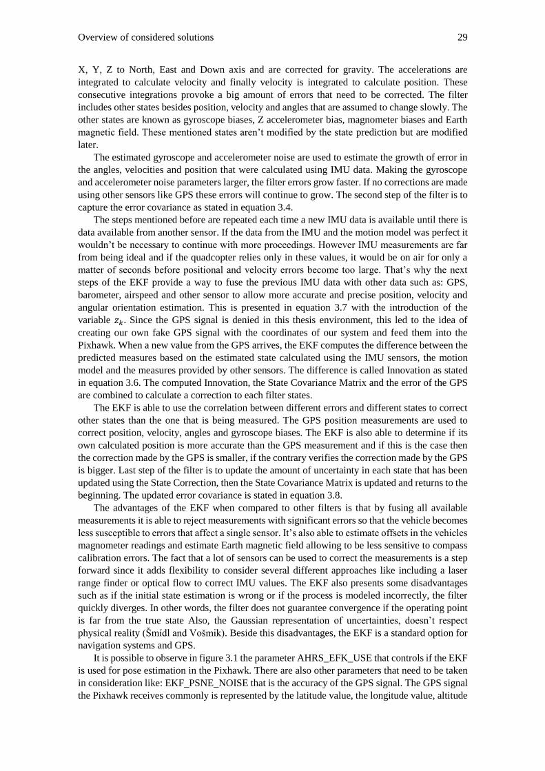
Overview of considered solutions 29
X, Y, Z to North, East and Down axis and are corrected for gravity. The accelerations are
integrated to calculate velocity and finally velocity is integrated to calculate position. These
consecutive integrations provoke a big amount of errors that need to be corrected. The filter
includes other states besides position, velocity and angles that are assumed to change slowly. The
other states are known as gyroscope biases, Z accelerometer bias, magnometer biases and Earth
magnetic field. These mentioned states aren’t modified by the state prediction but are modified
later.
The estimated gyroscope and accelerometer noise are used to estimate the growth of error in
the angles, velocities and position that were calculated using IMU data. Making the gyroscope
and accelerometer noise parameters larger, the filter errors grow faster. If no corrections are made
using other sensors like GPS these errors will continue to grow. The second step of the filter is to
capture the error covariance as stated in equation 3.4.
The steps mentioned before are repeated each time a new IMU data is available until there is
data available from another sensor. If the data from the IMU and the motion model was perfect it
wouldn’t be necessary to continue with more proceedings. However IMU measurements are far
from being ideal and if the quadcopter relies only in these values, it would be on air for only a
matter of seconds before positional and velocity errors become too large. That’s why the next
steps of the EKF provide a way to fuse the previous IMU data with other data such as: GPS,
barometer, airspeed and other sensor to allow more accurate and precise position, velocity and
angular orientation estimation. This is presented in equation 3.7 with the introduction of the
variable 𝑧𝑘 . Since the GPS signal is denied in this thesis environment, this led to the idea of
creating our own fake GPS signal with the coordinates of our system and feed them into the
Pixhawk. When a new value from the GPS arrives, the EKF computes the difference between the
predicted measures based on the estimated state calculated using the IMU sensors, the motion
model and the measures provided by other sensors. The difference is called Innovation as stated
in equation 3.6. The computed Innovation, the State Covariance Matrix and the error of the GPS
are combined to calculate a correction to each filter states.
The EKF is able to use the correlation between different errors and different states to correct
other states than the one that is being measured. The GPS position measurements are used to
correct position, velocity, angles and gyroscope biases. The EKF is also able to determine if its
own calculated position is more accurate than the GPS measurement and if this is the case then
the correction made by the GPS is smaller, if the contrary verifies the correction made by the GPS
is bigger. Last step of the filter is to update the amount of uncertainty in each state that has been
updated using the State Correction, then the State Covariance Matrix is updated and returns to the
beginning. The updated error covariance is stated in equation 3.8.
The advantages of the EKF when compared to other filters is that by fusing all available
measurements it is able to reject measurements with significant errors so that the vehicle becomes
less susceptible to errors that affect a single sensor. It’s also able to estimate offsets in the vehicles
magnometer readings and estimate Earth magnetic field allowing to be less sensitive to compass
calibration errors. The fact that a lot of sensors can be used to correct the measurements is a step
forward since it adds flexibility to consider several different approaches like including a laser
range finder or optical flow to correct IMU values. The EKF also presents some disadvantages
such as if the initial state estimation is wrong or if the process is modeled incorrectly, the filter
quickly diverges. In other words, the filter does not guarantee convergence if the operating point
is far from the true state Also, the Gaussian representation of uncertainties, doesn’t respect
physical reality (Šmídl and Vošmik). Beside this disadvantages, the EKF is a standard option for
navigation systems and GPS.
It is possible to observe in figure 3.1 the parameter AHRS_EFK_USE that controls if the EKF
is used for pose estimation in the Pixhawk. There are also other parameters that need to be taken
in consideration like: EKF_PSNE_NOISE that is the accuracy of the GPS signal. The GPS signal
the Pixhawk receives commonly is represented by the latitude value, the longitude value, altitude
30 System Specification
above sea level and other variables. These variables are used to build a sentence called NMEA
that the Pixhawk recognizes and unpacks. To reach to latitude and longitude values it’s necessary
to know the absolute position of the quadcopter in the environment. This is achieved with the
tracking of artificial markers on the ceiling.
Figure 3.1 - Screenshot Mission Planner Enable EKF
3.2 Solution Based in Artificial Markers
The calculation of the absolute position estimation is based in QR code (Quick Response
Code) recognition by a smartphone attached to the top platform of the quadcopter. Multiple QR
code are spread around the ceiling with the mobile device knowing the precise coordinates of
each code location when the code is decoded. The proposed system is displayed in figure 3.2:
Figure 3.2 - Solution Overview
QR code, in figure 3.3, is a type of visual tag, a 2D barcode but much more efficient than
normal tags that can bring many advantages to our system when compared to other more
expensive and complex solutions since they:
Are easy to produce;
Can store a large amount of data (URL links, geo coordinates and text);
Provide error correction function;
High speed recognition from every direction (perpendicular or oblique);
Are easy to maintain, it is only necessary to print it on a paper;
A possible disadvantage is that if the mobile device is far enough from the QR code, it might find
some troubles in recognizing it. However in normal buildings, where the ceiling isn’t too high
this problem doesn’t occur since the quadcopter will fly with a close distance from the ceiling. In
big warehouses, this solution can be a problem and the quadcopter would have to fly close to the
ceiling or other possible solution would be to increase the codes dimension. The codes could be
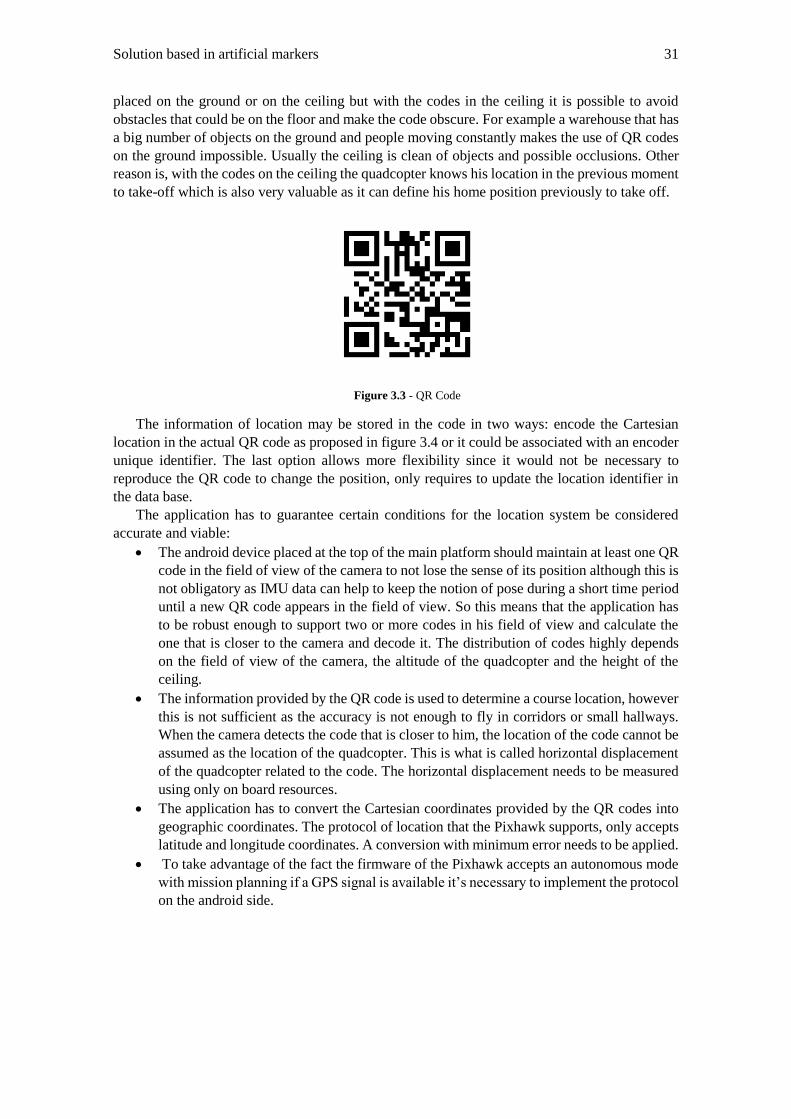
Solution based in artificial markers 31
placed on the ground or on the ceiling but with the codes in the ceiling it is possible to avoid
obstacles that could be on the floor and make the code obscure. For example a warehouse that has
a big number of objects on the ground and people moving constantly makes the use of QR codes
on the ground impossible. Usually the ceiling is clean of objects and possible occlusions. Other
reason is, with the codes on the ceiling the quadcopter knows his location in the previous moment
to take-off which is also very valuable as it can define his home position previously to take off.
Figure 3.3 - QR Code
The information of location may be stored in the code in two ways: encode the Cartesian
location in the actual QR code as proposed in figure 3.4 or it could be associated with an encoder
unique identifier. The last option allows more flexibility since it would not be necessary to
reproduce the QR code to change the position, only requires to update the location identifier in
the data base.
The application has to guarantee certain conditions for the location system be considered
accurate and viable:
The android device placed at the top of the main platform should maintain at least one QR
code in the field of view of the camera to not lose the sense of its position although this is
not obligatory as IMU data can help to keep the notion of pose during a short time period
until a new QR code appears in the field of view. So this means that the application has
to be robust enough to support two or more codes in his field of view and calculate the
one that is closer to the camera and decode it. The distribution of codes highly depends
on the field of view of the camera, the altitude of the quadcopter and the height of the
ceiling.
The information provided by the QR code is used to determine a course location, however
this is not sufficient as the accuracy is not enough to fly in corridors or small hallways.
When the camera detects the code that is closer to him, the location of the code cannot be
assumed as the location of the quadcopter. This is what is called horizontal displacement
of the quadcopter related to the code. The horizontal displacement needs to be measured
using only on board resources.
The application has to convert the Cartesian coordinates provided by the QR codes into
geographic coordinates. The protocol of location that the Pixhawk supports, only accepts
latitude and longitude coordinates. A conversion with minimum error needs to be applied.
To take advantage of the fact the firmware of the Pixhawk accepts an autonomous mode
with mission planning if a GPS signal is available it’s necessary to implement the protocol
on the android side.
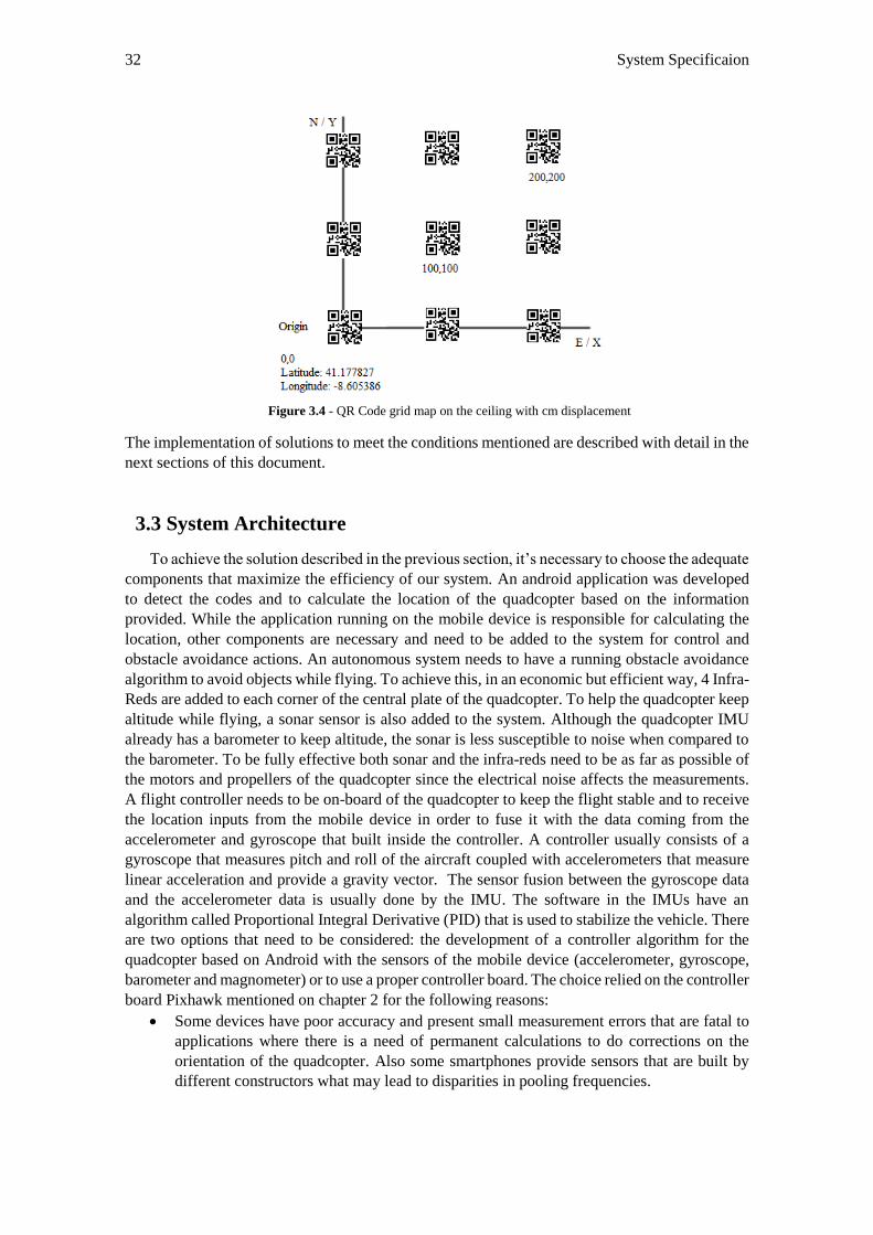
32 System Specificaion
Figure 3.4 - QR Code grid map on the ceiling with cm displacement
The implementation of solutions to meet the conditions mentioned are described with detail in the
next sections of this document.
3.3 System Architecture
To achieve the solution described in the previous section, it’s necessary to choose the adequate
components that maximize the efficiency of our system. An android application was developed
to detect the codes and to calculate the location of the quadcopter based on the information
provided. While the application running on the mobile device is responsible for calculating the
location, other components are necessary and need to be added to the system for control and
obstacle avoidance actions. An autonomous system needs to have a running obstacle avoidance
algorithm to avoid objects while flying. To achieve this, in an economic but efficient way, 4 Infra-
Reds are added to each corner of the central plate of the quadcopter. To help the quadcopter keep
altitude while flying, a sonar sensor is also added to the system. Although the quadcopter IMU
already has a barometer to keep altitude, the sonar is less susceptible to noise when compared to
the barometer. To be fully effective both sonar and the infra-reds need to be as far as possible of
the motors and propellers of the quadcopter since the electrical noise affects the measurements.
A flight controller needs to be on-board of the quadcopter to keep the flight stable and to receive
the location inputs from the mobile device in order to fuse it with the data coming from the
accelerometer and gyroscope that built inside the controller. A controller usually consists of a
gyroscope that measures pitch and roll of the aircraft coupled with accelerometers that measure
linear acceleration and provide a gravity vector. The sensor fusion between the gyroscope data
and the accelerometer data is usually done by the IMU. The software in the IMUs have an
algorithm called Proportional Integral Derivative (PID) that is used to stabilize the vehicle. There
are two options that need to be considered: the development of a controller algorithm for the
quadcopter based on Android with the sensors of the mobile device (accelerometer, gyroscope,
barometer and magnometer) or to use a proper controller board. The choice relied on the controller
board Pixhawk mentioned on chapter 2 for the following reasons:
Some devices have poor accuracy and present small measurement errors that are fatal to
applications where there is a need of permanent calculations to do corrections on the
orientation of the quadcopter. Also some smartphones provide sensors that are built by
different constructors what may lead to disparities in pooling frequencies.
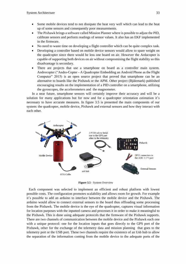
System Architecture 33
Some mobile devices tend to not dissipate the heat very well which can lead to the heat
up of some sensors and consequently poor measurements.
The Pixhawk brings a software called Mission Planner where is possible to adjust the PID,
calibrate sensors and perform readings of sensor values. It also has an EKF implemented
in the firmware.
No need to waste time on developing a flight controller which can be quite complex task.
Developing a controller based on mobile device sensors would allow to spare weight on
the quadcopter since there would be less one board on air. However the Arducopter is
capable of supporting both devices on air without compromising the flight stability so this
disadvantage is secondary.
There are projects that use a smartphone on board as a controller main system.
Androcopter (“Andro-Copter - A Quadcopter Embedding an Android Phone as the Flight
Computer” 2015) is an open source project that proved that smartphone can be an
alternative to boards like the Pixhawk or the APM. Other project (Bjälemark) published
encouraging results on the implementation of a PID controller on a smartphone, utilizing
the gyroscopes, the accelerometers and the magnometer.
In a near future, smartphone sensors will certainly improve their accuracy and will be a
solution for many applications but for now and for a quadcopter orientation estimation it’s
necessary to have accurate measures. In figure 3.5 is presented the main components of our
system: the quadcopter, mobile device, Pixhawk and external sensors and how they interact with
each other.
Figure 3.5 - System Overview
Each component was selected to implement an efficient and robust platform with lowest
possible costs. The configuration promotes scalability and allows room for growth. For example
it’s possible to add an arduino to interface between the mobile device and the Pixhawk. The
arduino would allow to connect external sensors to the board thus offloading some processing
from the Pixhawk. The mobile device is the eye of the quadcopter, captures visual information
for location purposes with the inputted camera and processes it in order to make it meaningful to
the Pixhawk. This is done using adequate protocols that the firmware of the Pixhawk supports.
There are two channels of communication between the mobile device and the Pixhawk each one
with a unique protocol: one for the location inputs that goes directly to the GPS port of the
Pixhawk, other for the exchange of the telemetry data and mission planning that goes to the
telemetry port or the USB port. These two channels require the existence of an Usb hub to allow
the separation of the information coming from the mobile device to the adequate ports of the
34 System Specification
Pixhawk. To enable the communication between the mobile device and the Pixhawk, it is
necessary an USB OTG cable. This allows the mobile device to act as a host and have the Pixhawk
attached to it as a peripheral device. When the smartphone is in host mode, it powers the bus
feeding the Pixhawk. The OTG cable is applied at the entrance of the android device and connects
to the Usb hub. From the hub to the Pixhawk, two FTDI TTL USB to serial converter cables are
used to allow data transfer. Note that only TTL cables can be used as the Pixhawk ports only
supports this cables. For example a common USB to serial FTDI RS232 can’t be used to exchange
information. One cable goes to the GPS port, the other goes to the telemetry port. It’s not
necessary to connect the VCC of the FTDI cables to the ports of the Pixhawk when flying as the
Pixhawk is already powered by the power module, only the respective TX-RX and GND. The
Pixhawk interfaces with the external sensors via the ADC 3.3V port.
3.4 System Specification Details
This section provides a more detailed specification of the most important hardware and
software modules that integrate this project.
3.4.1 Quadcopter
The ArduCopter was the quadcopter of the previous project. It was developed by 3DRobotics,
a major leading Drone Company in the US that makes advanced, capable and easy towards drone
systems for everyday exploration and business applications. After some consideration and
analysis of the quadcopters market it was decided to keep the quadcopter. To deliver the
objectives proposed in chapter 1.3 there is no better option on the market considering the
commercial quadcopters mentioned in 2.2.4. The quadcopter for this project needs to be small to
be able to fly in indoor environments where there are obstacles and doors. The noise levels from
motors and propellers needs to be low to don’t perturb the user comfort at home. But on the other
hand, the quadcopter needs to be able to carry some payload for on-board processing. The
Arducopter is the quadcopter that coops best with our needs since it is relatively small and at the
same time he is able to carry sensibly 2 kg of payload. Since the main weight are the mobile
device (160g) and the Pixhawk (50g) plus other small components as sensors or cables so there’s
no risk to surpass the maximum payload. This large weight limit also opens space to add other
platforms such as an Arduino to offload the processing of the Pixhawk.
The Arducopter displayed in figure 3.6 consists in four 880 kV (rpm/v) brushless motors, four
electronic speed controllers (ESC), 10 inch propeller set, body plates and black and blue arms.
However it needs additional components to the provided kit by 3DRobotics as a battery and extra
sensors for obstacle avoidance and altitude hold. The battery selected in the previous project was
a 4000 mAh 3S 30C Lipo Pack which is a rechargeable battery of lithium-ion technology. The
battery is able to last 15-20 minutes while flying, a common value for most quadcopters of this
size. Since the purpose of the quadcopter is to monitor small indoor environments like a house,
there will not exist the needs of flying large distances so this battery suits the project needs.
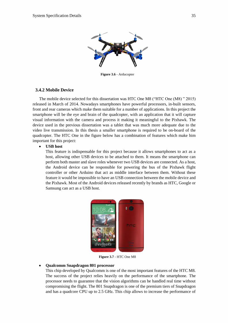
System Specification Details 35
Figure 3.6 - Arducopter
3.4.2 Mobile Device
The mobile device selected for this dissertation was HTC One M8 (“HTC One (M8) ” 2015)
released in March of 2014. Nowadays smartphones have powerful processors, in-built sensors,
front and rear cameras which make them suitable for a number of applications. In this project the
smartphone will be the eye and brain of the quadcopter, with an application that it will capture
visual information with the camera and process it making it meaningful to the Pixhawk. The
device used in the previous dissertation was a tablet that was much more adequate due to the
video live transmission. In this thesis a smaller smartphone is required to be on-board of the
quadcopter. The HTC One in the figure below has a combination of features which make him
important for this project:
USB host
This feature is indispensable for this project because it allows smartphones to act as a
host, allowing other USB devices to be attached to them. It means the smartphone can
perform both master and slave roles whenever two USB devices are connected. As a host,
the Android device can be responsible for powering the bus of the Pixhawk flight
controller or other Arduino that act as middle interface between them. Without these
feature it would be impossible to have an USB connection between the mobile device and
the Pixhawk. Most of the Android devices released recently by brands as HTC, Google or
Samsung can act as a USB host.
Figure 3.7 - HTC One M8
Qualcomm Snapdragon 801 processor
This chip developed by Qualcomm is one of the most important features of the HTC M8.
The success of the project relies heavily on the performance of the smartphone. The
processor needs to guarantee that the vision algorithms can be handled real time without
compromising the flight. The 801 Snapdragon is one of the premium tiers of Snapdragon
and has a quadcore CPU up to 2.5 GHz. This chip allows to increase the performance of
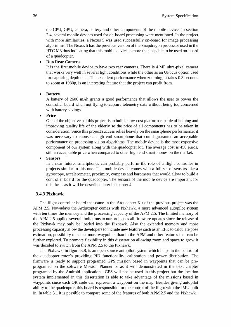
36 System Specification
the CPU, GPU, camera, battery and other components of the mobile device. In section
2.4, several mobile devices used for on-board processing were mentioned. In the project
with more similarities, a Nexus 5 was used successfully on-board for image processing
algorithms. The Nexus 5 has the previous version of the Snapdragon processor used in the
HTC M8 thus indicating that this mobile device is more than capable to be used on-board
of a quadcopter.
Duo Rear Camera
It is the first mobile device to have two rear cameras. There is 4 MP ultra-pixel camera
that works very well in several light conditions while the other as an UFocus option used
for capturing depth data. The excellent performance when zooming, it takes 0.3 seconds
to zoom at 1080p, is an interesting feature that the project can profit from.
Battery
A battery of 2600 mAh grants a good performance that allows the user to power the
controller board when not flying to capture telemetry data without being too concerned
with battery savings.
Price
One of the objectives of this project is to build a low-cost platform capable of helping and
improving quality life of the elderly so the price of all components has to be taken in
consideration. Since this project success relies heavily on the smartphone performance, it
was necessary to choose a high end smartphone that could guarantee an acceptable
performance on processing vision algorithms. The mobile device is the most expensive
component of our system along with the quadcopter kit. The average cost is 450 euros,
still an acceptable price when compared to other high end smartphones on the market.
Sensors
In a near future, smartphones can probably perform the role of a flight controller in
projects similar to this one. This mobile device comes with a full set of sensors like a
gyroscope, accelerometer, proximity, compass and barometer that would allow to build a
controller board for the quadcopter. The sensors of the mobile device are important for
this thesis as it will be described later in chapter 4.
3.4.3 Pixhawk
The flight controller board that came in the Arducopter Kit of the previous project was the
APM 2.5. Nowadays the Arducopter comes with Pixhawk, a more advanced autopilot system
with ten times the memory and the processing capacity of the APM 2.5. The limited memory of
the APM 2.5 applied several limitations to our project as all firmware updates since the release of
the Pixhawk may only be loaded into the Pixhawk. Also the extended memory and more
processing capacity allow the developers to include new features such as an EFK to calculate pose
estimation, possibility to select more waypoints than in the APM and other features that can be
further explored. To promote flexibility in this dissertation allowing room and space to grow it
was decided to switch from the APM 2.5 to the Pixhawk.
The Pixhawk, in figure 3.8, is an open source autopilot system which helps in the control of
the quadcopter rotor’s providing PID functionality, calibration and power distribution. The
firmware is ready to support programed GPS mission based in waypoints that can be pre-
programed on the software Mission Planner or as it will demonstrated in the next chapter
programed by the Android application. GPS will not be used in this project but the location
system implemented in this dissertation is able to take advantage of the missions based in
waypoints since each QR code can represent a waypoint on the map. Besides giving autopilot
ability to the quadcopter, this board is responsible for the control of the flight with the IMU built
in. In table 3.1 it is possible to compare some of the features of both APM 2.5 and the Pixhawk.
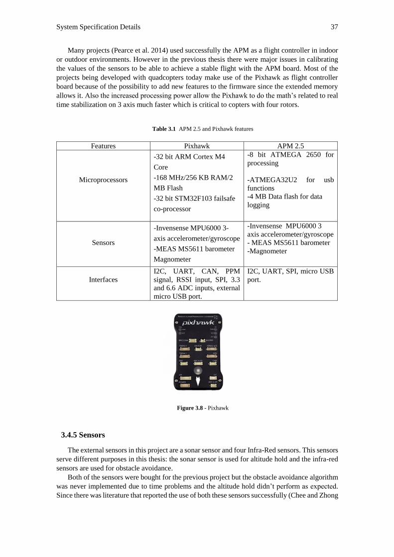
System Specification Details 37
Many projects (Pearce et al. 2014) used successfully the APM as a flight controller in indoor
or outdoor environments. However in the previous thesis there were major issues in calibrating
the values of the sensors to be able to achieve a stable flight with the APM board. Most of the
projects being developed with quadcopters today make use of the Pixhawk as flight controller
board because of the possibility to add new features to the firmware since the extended memory
allows it. Also the increased processing power allow the Pixhawk to do the math’s related to real
time stabilization on 3 axis much faster which is critical to copters with four rotors.
Table 3.1 APM 2.5 and Pixhawk features
Figure 3.8 - Pixhawk
3.4.5 Sensors
The external sensors in this project are a sonar sensor and four Infra-Red sensors. This sensors
serve different purposes in this thesis: the sonar sensor is used for altitude hold and the infra-red
sensors are used for obstacle avoidance.
Both of the sensors were bought for the previous project but the obstacle avoidance algorithm
was never implemented due to time problems and the altitude hold didn’t perform as expected.
Since there was literature that reported the use of both these sensors successfully (Chee and Zhong
Features Pixhawk APM 2.5
Microprocessors
-32 bit ARM Cortex M4
Core
-168 MHz/256 KB RAM/2
MB Flash
-32 bit STM32F103 failsafe
co-processor
-8 bit ATMEGA 2650 for
processing
-ATMEGA32U2 for usb
functions
-4 MB Data flash for data
logging
Sensors
-Invensense MPU6000 3-
axis accelerometer/gyroscope
-MEAS MS5611 barometer
Magnometer
-Invensense MPU6000 3
axis accelerometer/gyroscope
- MEAS MS5611 barometer
-Magnometer
Interfaces
I2C, UART, CAN, PPM
signal, RSSI input, SPI, 3.3
and 6.6 ADC inputs, external
micro USB port.
I2C, UART, SPI, micro USB
port.
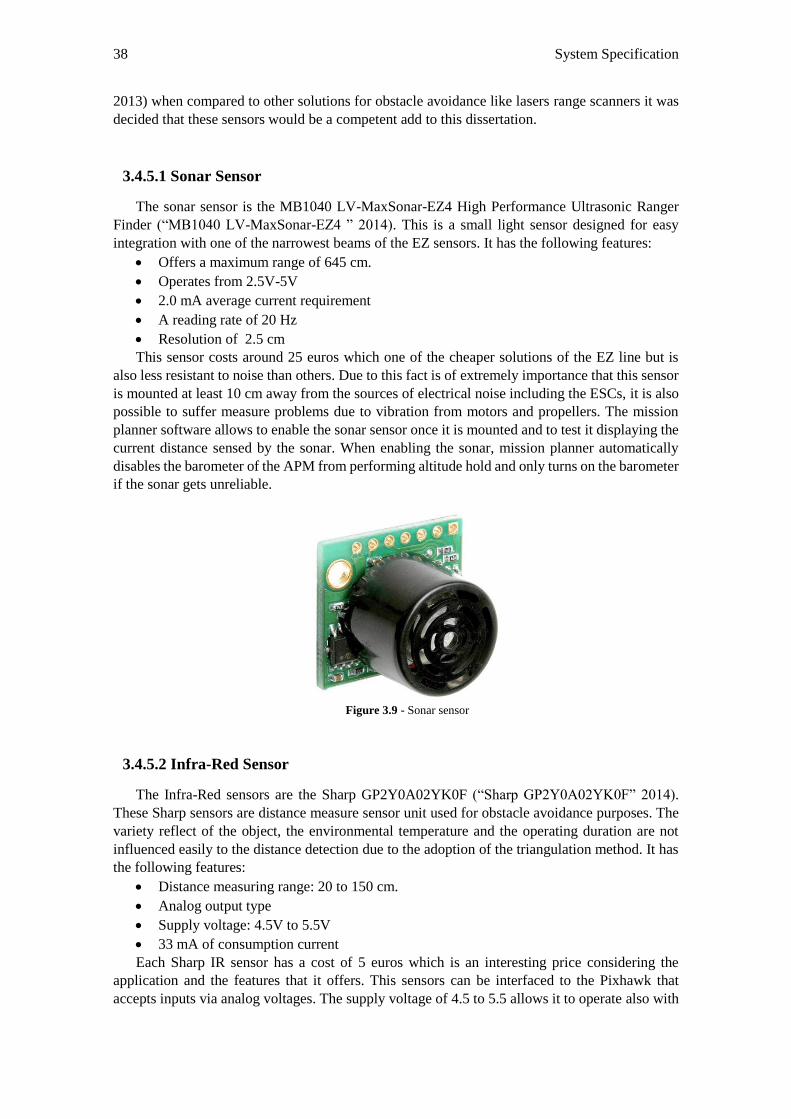
38 System Specification
2013) when compared to other solutions for obstacle avoidance like lasers range scanners it was
decided that these sensors would be a competent add to this dissertation.
3.4.5.1 Sonar Sensor
The sonar sensor is the MB1040 LV-MaxSonar-EZ4 High Performance Ultrasonic Ranger
Finder (“MB1040 LV-MaxSonar-EZ4 ” 2014). This is a small light sensor designed for easy
integration with one of the narrowest beams of the EZ sensors. It has the following features:
Offers a maximum range of 645 cm.
Operates from 2.5V-5V
2.0 mA average current requirement
A reading rate of 20 Hz
Resolution of 2.5 cm
This sensor costs around 25 euros which one of the cheaper solutions of the EZ line but is
also less resistant to noise than others. Due to this fact is of extremely importance that this sensor
is mounted at least 10 cm away from the sources of electrical noise including the ESCs, it is also
possible to suffer measure problems due to vibration from motors and propellers. The mission
planner software allows to enable the sonar sensor once it is mounted and to test it displaying the
current distance sensed by the sonar. When enabling the sonar, mission planner automatically
disables the barometer of the APM from performing altitude hold and only turns on the barometer
if the sonar gets unreliable.
Figure 3.9 - Sonar sensor
3.4.5.2 Infra-Red Sensor
The Infra-Red sensors are the Sharp GP2Y0A02YK0F (“Sharp GP2Y0A02YK0F” 2014).
These Sharp sensors are distance measure sensor unit used for obstacle avoidance purposes. The
variety reflect of the object, the environmental temperature and the operating duration are not
influenced easily to the distance detection due to the adoption of the triangulation method. It has
the following features:
Distance measuring range: 20 to 150 cm.
Analog output type
Supply voltage: 4.5V to 5.5V
33 mA of consumption current
Each Sharp IR sensor has a cost of 5 euros which is an interesting price considering the
application and the features that it offers. This sensors can be interfaced to the Pixhawk that
accepts inputs via analog voltages. The supply voltage of 4.5 to 5.5 allows it to operate also with
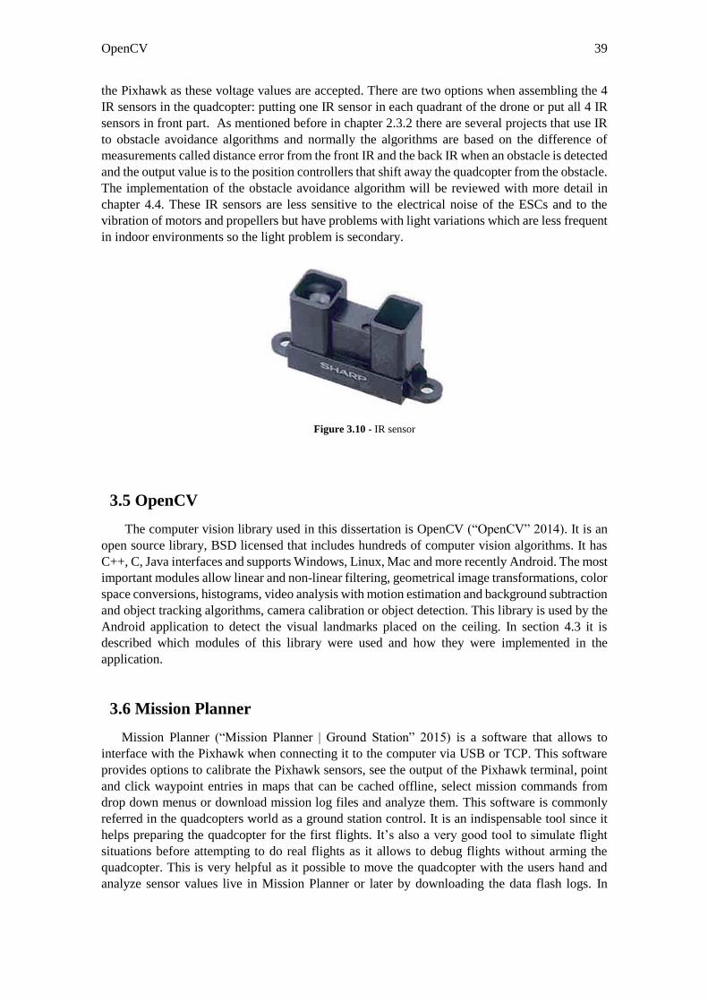
OpenCV 39
the Pixhawk as these voltage values are accepted. There are two options when assembling the 4
IR sensors in the quadcopter: putting one IR sensor in each quadrant of the drone or put all 4 IR
sensors in front part. As mentioned before in chapter 2.3.2 there are several projects that use IR
to obstacle avoidance algorithms and normally the algorithms are based on the difference of
measurements called distance error from the front IR and the back IR when an obstacle is detected
and the output value is to the position controllers that shift away the quadcopter from the obstacle.
The implementation of the obstacle avoidance algorithm will be reviewed with more detail in
chapter 4.4. These IR sensors are less sensitive to the electrical noise of the ESCs and to the
vibration of motors and propellers but have problems with light variations which are less frequent
in indoor environments so the light problem is secondary.
Figure 3.10 - IR sensor
3.5 OpenCV
The computer vision library used in this dissertation is OpenCV (“OpenCV” 2014). It is an
open source library, BSD licensed that includes hundreds of computer vision algorithms. It has
C++, C, Java interfaces and supports Windows, Linux, Mac and more recently Android. The most
important modules allow linear and non-linear filtering, geometrical image transformations, color
space conversions, histograms, video analysis with motion estimation and background subtraction
and object tracking algorithms, camera calibration or object detection. This library is used by the
Android application to detect the visual landmarks placed on the ceiling. In section 4.3 it is
described which modules of this library were used and how they were implemented in the
application.
3.6 Mission Planner
Mission Planner (“Mission Planner | Ground Station” 2015) is a software that allows to
interface with the Pixhawk when connecting it to the computer via USB or TCP. This software
provides options to calibrate the Pixhawk sensors, see the output of the Pixhawk terminal, point
and click waypoint entries in maps that can be cached offline, select mission commands from
drop down menus or download mission log files and analyze them. This software is commonly
referred in the quadcopters world as a ground station control. It is an indispensable tool since it
helps preparing the quadcopter for the first flights. It’s also a very good tool to simulate flight
situations before attempting to do real flights as it allows to debug flights without arming the
quadcopter. This is very helpful as it possible to move the quadcopter with the users hand and
analyze sensor values live in Mission Planner or later by downloading the data flash logs. In
40 System Specification
section 4.2, is described with more detail how mission planner was used in this dissertation to
help setup the quadcopter for indoor flights.
3.7 Summary
This chapter covers all important hardware and software modules on this projects used to
fulfill the thesis objectives.
First was presented an overview of the all the considered solutions, then the solution to be
implemented was described, a detail description of the system architecture to achieve the
proposed solution, which hardware and software modules were used, why they were used and
how they are connected to each other. Then each module was specified where some of the most
important features of each module were mentioned with special emphasis on the quadcopter, the
mobile device and the Pixhawk.
41
Chapter 4
System Implementation
This chapter provides a close look on the solutions found to overcome the challenges of this
dissertation in order to build a functional prototype capable of performing the objectives defined
in chapter 1.
4.1 Assembling Hardware Connections
This section approaches how every hardware module of our system was connected. In chapter
3 some hardware components were presented such as the quadcopter itself along with the battery,
the Pixhawk, the mobile device and the external sensors. The final configuration is displayed in
figure 4.1 and 4.2 with all the hardware modules connected.
Battery
The battery is placed on the bottom of the main platform tied with proper straps. It is
important that the battery keeps still while flying to not interfere with flight stability. It
also has to be placed as center as possible. The battery connects to the power module port
of the Pixhawk and is responsible for powering the Pixhawk during flight. In the figure
4.1 the battery matches number 3.
Pixhawk
The Pixhawk is placed in the main platform right in the middle of the quadcopter. This
place is ideal due to all the things that need to be connected to this board can reach it with
no significant effort. As said before, the Pixhawk is powered by the battery. There are
several components connected to the ports of the Pixhawk: the mobile device, a sonar
sensor, a switch, a buzzer, a PPM receiver to receive RC inputs and the ESC that control
the speed of each individual motor. Both switch and buzzer are components for added
safety. The switch is a led that indicates the system status and the buzzer produces
different sounds that allow to debug operations that occur previously to the flight. In
figure 4.1 the Pixhawk is number 2.
Mobile Device
The mobile device is at the top of the main platform in order to have clear view to track
the landmark codes in the ceiling. It is connected to an Usb hub via an OTG cable to allow
host functions. Two FTDI Usb to serial cables go from the hub to the GPS port and
telemetry port of the Pixhawk. The connection between the mobile device and the
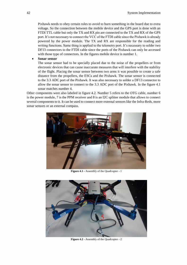
42 System Implementation
Pixhawk needs to obey certain rules to avoid to burn something in the board due to extra
voltage. So the connection between the mobile device and the GPS port is done with an
FTDI TTL cable but only the TX and RX pin are connected to the TX and RX of the GPS
port. It’s not necessary to connect the VCC of the FTDI cable since the Pixhawk is already
powered by the power module. The TX and RX are responsible for the reading and
writing functions. Same thing is applied to the telemetry port. It’s necessary to solder two
DF13 connectors to the FTDI cable since the ports of the Pixhawk can only be accessed
with those type of connectors. In the figures mobile device is number 1.
Sonar sensor
The sonar sensor had to be specially placed due to the noise of the propellers or from
electronic devices that can cause inaccurate measures that will interfere with the stability
of the flight. Placing the sonar sensor between two arms it was possible to create a safe
distance from the propellers, the ESCs and the Pixhawk. The sonar sensor is connected
to the 3.3 ADC port of the Pixhawk. It was also necessary to solder a DF13 connector to
allow the sonar sensor to connect to the 3.3 ADC port of the Pixhawk. In the figure 4.1
sonar matches number 4.
Other components were also labeled in figure 4.2. Number 5 refers to the OTG cable, number 6
is the power module, 7 is the PPM receiver and 8 is an I2C splitter module that allows to connect
several components to it. It can be used to connect more external sensors like the Infra-Reds, more
sonar sensors or an external compass.
Figure 4.1 - Assembly of the Quadcopter - 1
Figure 4.2 - Assembly of the Quadcopter - 2
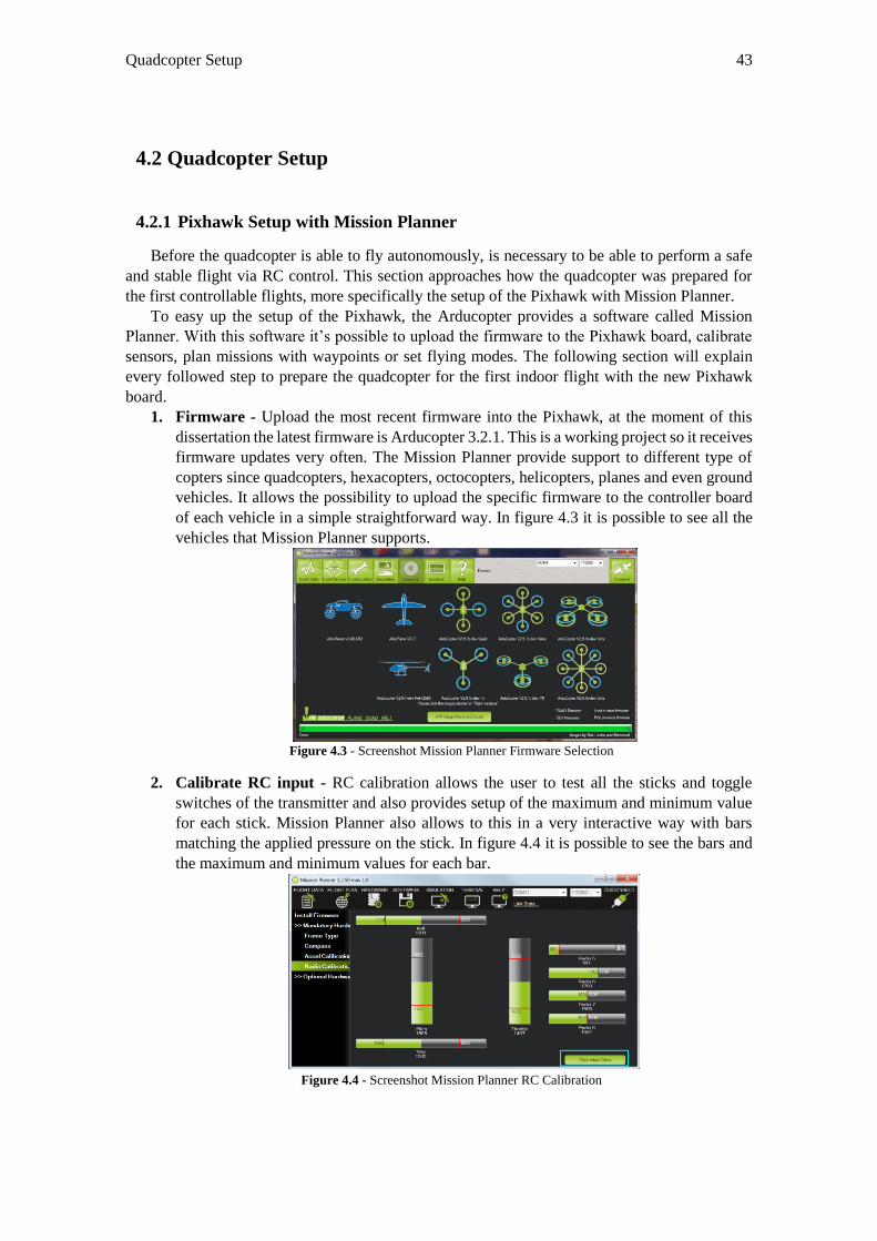
Quadcopter Setup 43
4.2 Quadcopter Setup
4.2.1 Pixhawk Setup with Mission Planner
Before the quadcopter is able to fly autonomously, is necessary to be able to perform a safe
and stable flight via RC control. This section approaches how the quadcopter was prepared for
the first controllable flights, more specifically the setup of the Pixhawk with Mission Planner.
To easy up the setup of the Pixhawk, the Arducopter provides a software called Mission
Planner. With this software it’s possible to upload the firmware to the Pixhawk board, calibrate
sensors, plan missions with waypoints or set flying modes. The following section will explain
every followed step to prepare the quadcopter for the first indoor flight with the new Pixhawk
board.
1. Firmware - Upload the most recent firmware into the Pixhawk, at the moment of this
dissertation the latest firmware is Arducopter 3.2.1. This is a working project so it receives
firmware updates very often. The Mission Planner provide support to different type of
copters since quadcopters, hexacopters, octocopters, helicopters, planes and even ground
vehicles. It allows the possibility to upload the specific firmware to the controller board
of each vehicle in a simple straightforward way. In figure 4.3 it is possible to see all the
vehicles that Mission Planner supports.
Figure 4.3 - Screenshot Mission Planner Firmware Selection
2. Calibrate RC input - RC calibration allows the user to test all the sticks and toggle
switches of the transmitter and also provides setup of the maximum and minimum value
for each stick. Mission Planner also allows to this in a very interactive way with bars
matching the applied pressure on the stick. In figure 4.4 it is possible to see the bars and
the maximum and minimum values for each bar.
Figure 4.4 - Screenshot Mission Planner RC Calibration
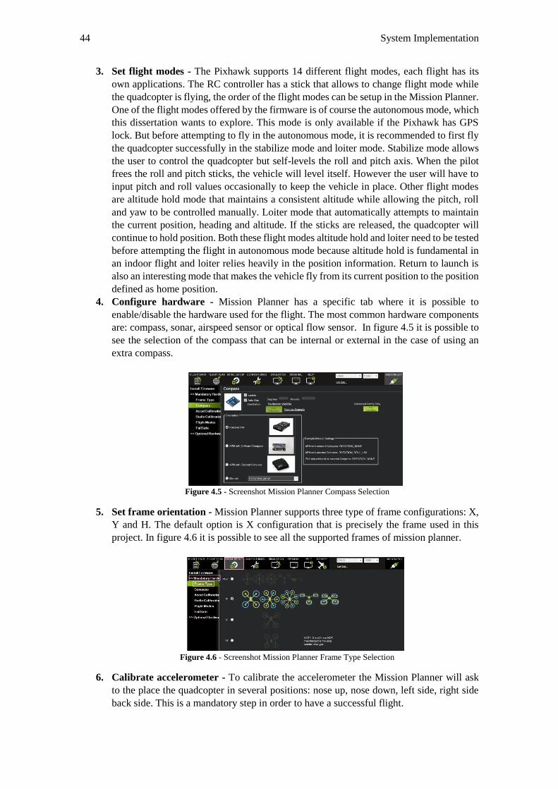
44 System Implementation
3. Set flight modes - The Pixhawk supports 14 different flight modes, each flight has its
own applications. The RC controller has a stick that allows to change flight mode while
the quadcopter is flying, the order of the flight modes can be setup in the Mission Planner.
One of the flight modes offered by the firmware is of course the autonomous mode, which
this dissertation wants to explore. This mode is only available if the Pixhawk has GPS
lock. But before attempting to fly in the autonomous mode, it is recommended to first fly
the quadcopter successfully in the stabilize mode and loiter mode. Stabilize mode allows
the user to control the quadcopter but self-levels the roll and pitch axis. When the pilot
frees the roll and pitch sticks, the vehicle will level itself. However the user will have to
input pitch and roll values occasionally to keep the vehicle in place. Other flight modes
are altitude hold mode that maintains a consistent altitude while allowing the pitch, roll
and yaw to be controlled manually. Loiter mode that automatically attempts to maintain
the current position, heading and altitude. If the sticks are released, the quadcopter will
continue to hold position. Both these flight modes altitude hold and loiter need to be tested
before attempting the flight in autonomous mode because altitude hold is fundamental in
an indoor flight and loiter relies heavily in the position information. Return to launch is
also an interesting mode that makes the vehicle fly from its current position to the position
defined as home position.
4. Configure hardware - Mission Planner has a specific tab where it is possible to
enable/disable the hardware used for the flight. The most common hardware components
are: compass, sonar, airspeed sensor or optical flow sensor. In figure 4.5 it is possible to
see the selection of the compass that can be internal or external in the case of using an
extra compass.
Figure 4.5 - Screenshot Mission Planner Compass Selection
5. Set frame orientation - Mission Planner supports three type of frame configurations: X,
Y and H. The default option is X configuration that is precisely the frame used in this
project. In figure 4.6 it is possible to see all the supported frames of mission planner.
Figure 4.6 - Screenshot Mission Planner Frame Type Selection
6. Calibrate accelerometer - To calibrate the accelerometer the Mission Planner will ask
to the place the quadcopter in several positions: nose up, nose down, left side, right side
back side. This is a mandatory step in order to have a successful flight.
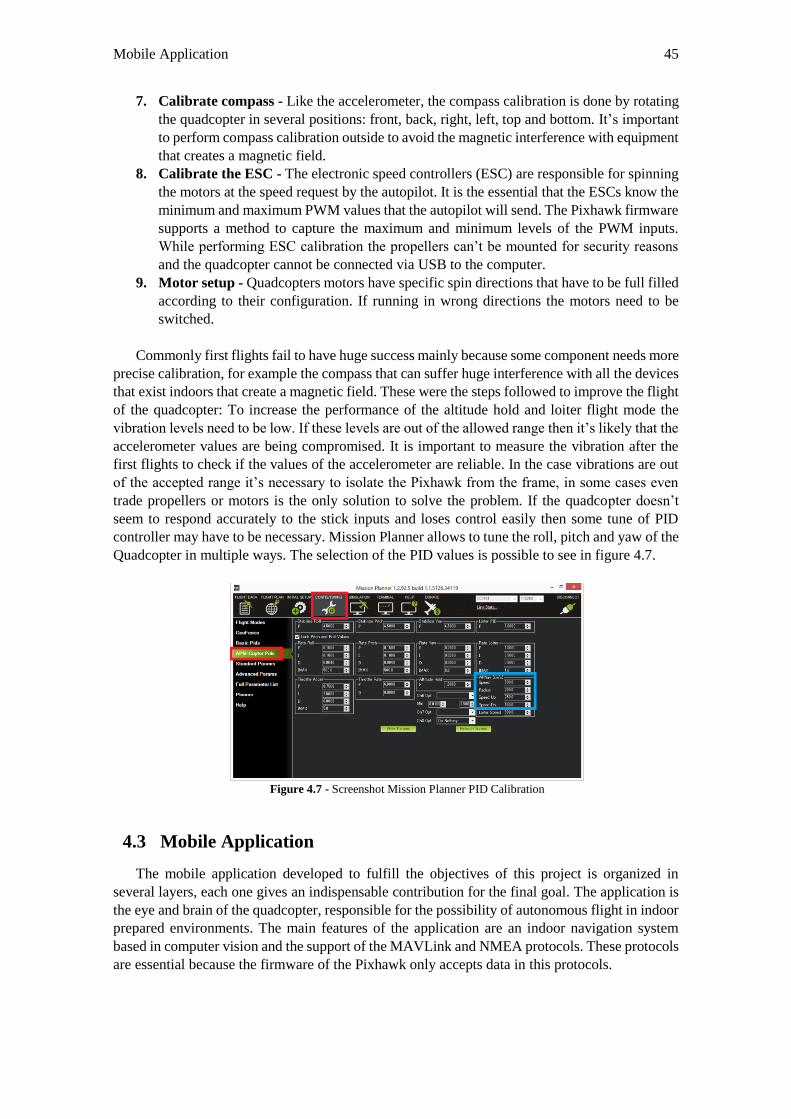
Mobile Application 45
7. Calibrate compass - Like the accelerometer, the compass calibration is done by rotating
the quadcopter in several positions: front, back, right, left, top and bottom. It’s important
to perform compass calibration outside to avoid the magnetic interference with equipment
that creates a magnetic field.
8. Calibrate the ESC - The electronic speed controllers (ESC) are responsible for spinning
the motors at the speed request by the autopilot. It is the essential that the ESCs know the
minimum and maximum PWM values that the autopilot will send. The Pixhawk firmware
supports a method to capture the maximum and minimum levels of the PWM inputs.
While performing ESC calibration the propellers can’t be mounted for security reasons
and the quadcopter cannot be connected via USB to the computer.
9. Motor setup - Quadcopters motors have specific spin directions that have to be full filled
according to their configuration. If running in wrong directions the motors need to be
switched.
Commonly first flights fail to have huge success mainly because some component needs more
precise calibration, for example the compass that can suffer huge interference with all the devices
that exist indoors that create a magnetic field. These were the steps followed to improve the flight
of the quadcopter: To increase the performance of the altitude hold and loiter flight mode the
vibration levels need to be low. If these levels are out of the allowed range then it’s likely that the
accelerometer values are being compromised. It is important to measure the vibration after the
first flights to check if the values of the accelerometer are reliable. In the case vibrations are out
of the accepted range it’s necessary to isolate the Pixhawk from the frame, in some cases even
trade propellers or motors is the only solution to solve the problem. If the quadcopter doesn’t
seem to respond accurately to the stick inputs and loses control easily then some tune of PID
controller may have to be necessary. Mission Planner allows to tune the roll, pitch and yaw of the
Quadcopter in multiple ways. The selection of the PID values is possible to see in figure 4.7.
Figure 4.7 - Screenshot Mission Planner PID Calibration
4.3 Mobile Application
The mobile application developed to fulfill the objectives of this project is organized in
several layers, each one gives an indispensable contribution for the final goal. The application is
the eye and brain of the quadcopter, responsible for the possibility of autonomous flight in indoor
prepared environments. The main features of the application are an indoor navigation system
based in computer vision and the support of the MAVLink and NMEA protocols. These protocols
are essential because the firmware of the Pixhawk only accepts data in this protocols.
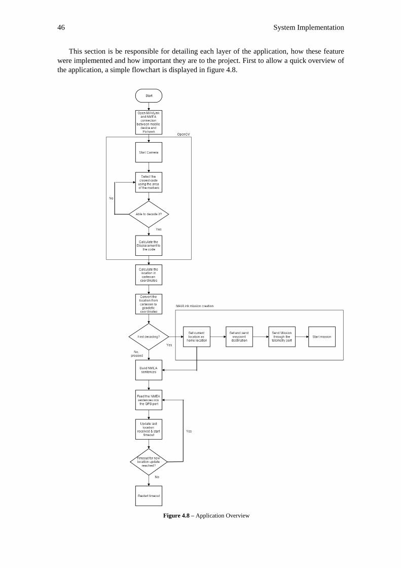
46 System Implementation
This section is be responsible for detailing each layer of the application, how these feature
were implemented and how important they are to the project. First to allow a quick overview of
the application, a simple flowchart is displayed in figure 4.8.
Figure 4.8 – Application Overview
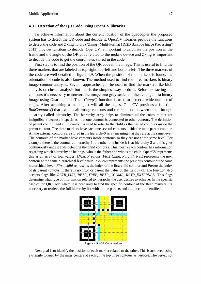
Mobile Application 47
4.3.1 Detection of the QR Code Using OpenCV libraries
To achieve information about the current location of the quadcopter the proposed
system has to detect the QR code and decode it. OpenCV libraries provide the functions
to detect the code and Zxing library (“Zxing - Multi-Format 1D/2D Barcode Image Processing”
2015) provides functions to decode. OpenCV is important to calculate the position in the
frame and the angle of the QR code related to the mobile device and Zxing is important
to decode the code to get the coordinates stored in the code.
First step is to find the position of the QR code in the image. This is useful to find the
three markers that are labeled as top-right, top-left and bottom-left. The three markers of
the code are well detailed in figure 4.9. When the position of the markers is found, the
orientation of code is also known. The method used to find the three markers is binary
image contour analysis. Several approaches can be used to find the markers like blob
analysis or cluster analysis but this is the simplest way to do it. Before extracting the
contours it’s necessary to convert the image into gray scale and then change it to binary
image using Otsu method. Then Canny() function is used to detect a wide number of
edges. After acquiring a mat object will all the edges, OpenCV provides a function
findContours() that extracts all image contours and the relations between them through
an array called hierarchy. The hierarchy array helps to eliminate all the contours that are
insignificant because it specifies how one contour is connected to other contour. The definition
of parent contour and child contour is used to refer to the child as the nested contours inside the
parent contour. The three markers have each one several contours inside the main parent contour.
All the external contours are stored in the hierarchy0 array meaning that they are at the same level.
The contours of the marker have contours inside contours so they are not at the same level. For
example there is the contour at hierarchy-1, the other one inside it is at hierarchy-2 and this goes
continuously until it ends detecting the child contours. This means each contour has information
regarding which hierarchy he belongs, who is the father and who is the child. OpenCV represents
this as an array of four values: [Next, Previous, First_Child, Parent]. Next represents the next
contour at the same hierarchical level while Previous represents the previous contour at the same
hierarchical level. First_child represents the index of the first child contour and Parent the index
of its parent contour. If there is no child or parent the value of the field is -1. The function also
accepts flags like RETR_LIST, RETR_TREE, RETR_CCOMP, RETR_EXTERNAL. This flags
determine what type of information related to hierarchy the user desires to achieve. In the specific
case of the QR Code where it is necessary to find the specific contour of the three markers it’s
necessary to retrieve the full hierarchy list with all the parents and all the child identified.
Figure 4.9 - QR Code markers
Next goal is to identify the position of each marker related to the other. This is achieved using
a triangle formed by the mass centers of each of the top three contours as vertices. The vertex not
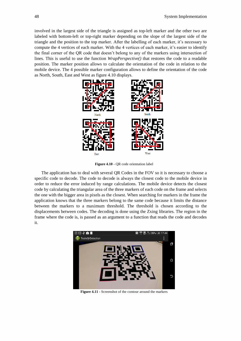
48 System Implementation
involved in the largest side of the triangle is assigned as top-left marker and the other two are
labeled with bottom-left or top-right marker depending on the slope of the largest side of the
triangle and the position to the top marker. After the labelling of each marker, it’s necessary to
compute the 4 vertices of each marker. With the 4 vertices of each marker, it’s easier to identify
the final corner of the QR code that doesn’t belong to any of the markers using intersection of
lines. This is useful to use the function WrapPerspective() that restores the code to a readable
position. The marker position allows to calculate the orientation of the code in relation to the
mobile device. The 4 possible marker configuration allows to define the orientation of the code
as North, South, East and West as figure 4.10 displays.
Figure 4.10 - QR code orientation label
The application has to deal with several QR Codes in the FOV so it is necessary to choose a
specific code to decode. The code to decode is always the closest code to the mobile device in
order to reduce the error induced by range calculations. The mobile device detects the closest
code by calculating the triangular area of the three markers of each code on the frame and selects
the one with the bigger area in pixels as the closest. When searching for markers in the frame the
application knows that the three markers belong to the same code because it limits the distance
between the markers to a maximum threshold. The threshold is chosen according to the
displacements between codes. The decoding is done using the Zxing libraries. The region in the
frame where the code is, is passed as an argument to a function that reads the code and decodes
it.
Figure 4.11 - Screenshot of the contour around the markers
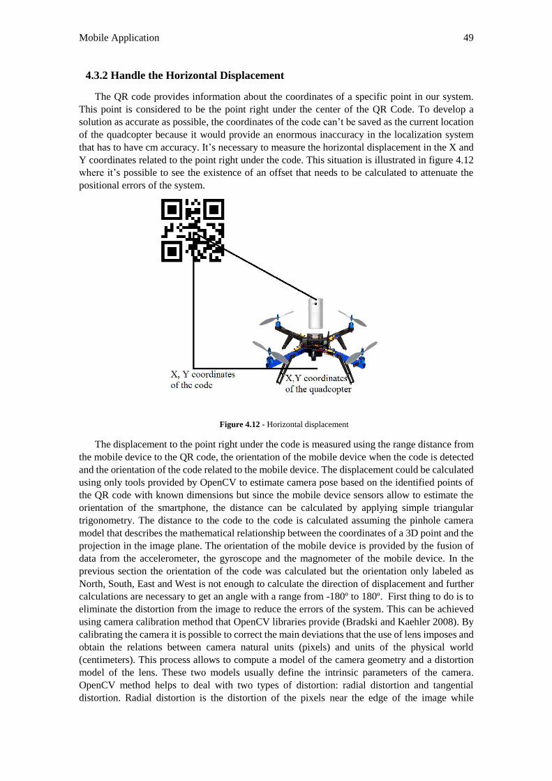
Mobile Application 49
4.3.2 Handle the Horizontal Displacement
The QR code provides information about the coordinates of a specific point in our system.
This point is considered to be the point right under the center of the QR Code. To develop a
solution as accurate as possible, the coordinates of the code can’t be saved as the current location
of the quadcopter because it would provide an enormous inaccuracy in the localization system
that has to have cm accuracy. It’s necessary to measure the horizontal displacement in the X and
Y coordinates related to the point right under the code. This situation is illustrated in figure 4.12
where it’s possible to see the existence of an offset that needs to be calculated to attenuate the
positional errors of the system.
Figure 4.12 - Horizontal displacement
The displacement to the point right under the code is measured using the range distance from
the mobile device to the QR code, the orientation of the mobile device when the code is detected
and the orientation of the code related to the mobile device. The displacement could be calculated
using only tools provided by OpenCV to estimate camera pose based on the identified points of
the QR code with known dimensions but since the mobile device sensors allow to estimate the
orientation of the smartphone, the distance can be calculated by applying simple triangular
trigonometry. The distance to the code to the code is calculated assuming the pinhole camera
model that describes the mathematical relationship between the coordinates of a 3D point and the
projection in the image plane. The orientation of the mobile device is provided by the fusion of
data from the accelerometer, the gyroscope and the magnometer of the mobile device. In the
previous section the orientation of the code was calculated but the orientation only labeled as
North, South, East and West is not enough to calculate the direction of displacement and further
calculations are necessary to get an angle with a range from -180º to 180º. First thing to do is to
eliminate the distortion from the image to reduce the errors of the system. This can be achieved
using camera calibration method that OpenCV libraries provide (Bradski and Kaehler 2008). By
calibrating the camera it is possible to correct the main deviations that the use of lens imposes and
obtain the relations between camera natural units (pixels) and units of the physical world
(centimeters). This process allows to compute a model of the camera geometry and a distortion
model of the lens. These two models usually define the intrinsic parameters of the camera.
OpenCV method helps to deal with two types of distortion: radial distortion and tangential
distortion. Radial distortion is the distortion of the pixels near the edge of the image while
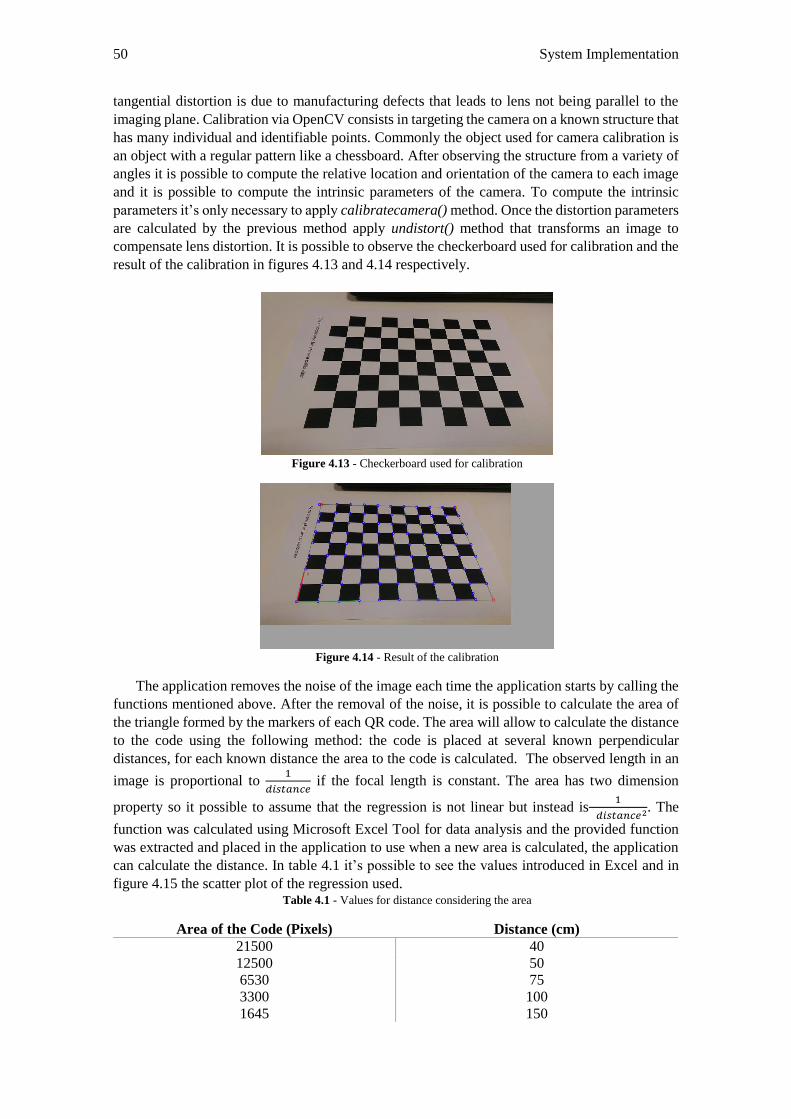
50 System Implementation
tangential distortion is due to manufacturing defects that leads to lens not being parallel to the
imaging plane. Calibration via OpenCV consists in targeting the camera on a known structure that
has many individual and identifiable points. Commonly the object used for camera calibration is
an object with a regular pattern like a chessboard. After observing the structure from a variety of
angles it is possible to compute the relative location and orientation of the camera to each image
and it is possible to compute the intrinsic parameters of the camera. To compute the intrinsic
parameters it’s only necessary to apply calibratecamera() method. Once the distortion parameters
are calculated by the previous method apply undistort() method that transforms an image to
compensate lens distortion. It is possible to observe the checkerboard used for calibration and the
result of the calibration in figures 4.13 and 4.14 respectively.
Figure 4.13 - Checkerboard used for calibration
Figure 4.14 - Result of the calibration
The application removes the noise of the image each time the application starts by calling the
functions mentioned above. After the removal of the noise, it is possible to calculate the area of
the triangle formed by the markers of each QR code. The area will allow to calculate the distance
to the code using the following method: the code is placed at several known perpendicular
distances, for each known distance the area to the code is calculated. The observed length in an
image is proportional to 1
𝑑𝑖𝑠𝑡𝑎𝑛𝑐𝑒 if the focal length is constant. The area has two dimension
property so it possible to assume that the regression is not linear but instead is1
𝑑𝑖𝑠𝑡𝑎𝑛𝑐𝑒2. The
function was calculated using Microsoft Excel Tool for data analysis and the provided function
was extracted and placed in the application to use when a new area is calculated, the application
can calculate the distance. In table 4.1 it’s possible to see the values introduced in Excel and in
figure 4.15 the scatter plot of the regression used. Table 4.1 - Values for distance considering the area
Area of the Code (Pixels) Distance (cm)
21500 40
12500 50
6530 75
3300 100
1645 150
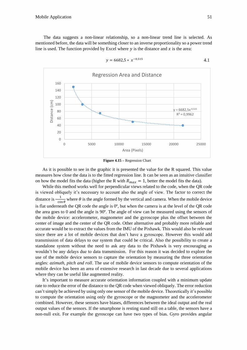
Mobile Application 51
The data suggests a non-linear relationship, so a non-linear trend line is selected. As
mentioned before, the data will be something closer to an inverse proportionality so a power trend
line is used. The function provided by Excel where 𝑦 is the distance and 𝑥 is the area:
𝑦 = 6682,5 ∗ 𝑥−0,515 4.1
Figure 4.15 – Regression Chart
As it is possible to see in the graphic it is presented the value for the R squared. This value
measures how close the data is to the fitted regression line. It can be seen as an intuitive classifier
on how the model fits the data (higher the R with 𝑅𝑚𝑎𝑥 = 1, better the model fits the data).
While this method works well for perpendicular views related to the code, when the QR code
is viewed obliquely it’s necessary to account also the angle of view. The factor to correct the
distance is 1
cos𝜃 where 𝜃 is the angle formed by the vertical and camera. When the mobile device
is flat underneath the QR code the angle is 0º, but when the camera is at the level of the QR code
the area goes to 0 and the angle is 90º. The angle of view can be measured using the sensors of
the mobile device: accelerometer, magnometer and the gyroscope plus the offset between the
center of image and the center of the QR code. Other alternative and probably more reliable and
accurate would be to extract the values from the IMU of the Pixhawk. This would also be relevant
since there are a lot of mobile devices that don’t have a gyroscope. However this would add
transmission of data delays to our system that could be critical. Also the possibility to create a
standalone system without the need to ask any data to the Pixhawk is very encouraging as
wouldn’t be any delays due to data transmission. For this reason it was decided to explore the
use of the mobile device sensors to capture the orientation by measuring the three orientation
angles: azimuth, pitch and roll. The use of mobile device sensors to compute orientation of the
mobile device has been an area of extensive research in last decade due to several applications
where they can be useful like augmented reality.
It’s important to measure accurate orientation information coupled with a minimum update
rate to reduce the error of the distance to the QR code when viewed obliquely. The error reduction
can’t simply be achieved by using only one sensor of the mobile device. Theoretically it’s possible
to compute the orientation using only the gyroscope or the magnometer and the accelerometer
combined. However, these sensors have biases, differences between the ideal output and the real
output values of the sensors. If the smartphone is resting stand still on a table, the sensors have a
non-null exit. For example the gyroscope can have two types of bias. Gyro provides angular
y = 6682,5x-0,515
R² = 0,9962
0
20
40
60
80
100
120
140
160
0 5000 10000 15000 20000 25000
Dis
tan
ce (
cm)
Area (Pixels)
Regression Area and Distance
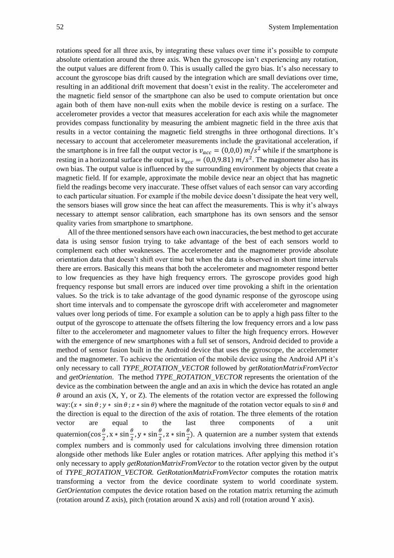
52 System Implementation
rotations speed for all three axis, by integrating these values over time it’s possible to compute
absolute orientation around the three axis. When the gyroscope isn’t experiencing any rotation,
the output values are different from 0. This is usually called the gyro bias. It’s also necessary to
account the gyroscope bias drift caused by the integration which are small deviations over time,
resulting in an additional drift movement that doesn’t exist in the reality. The accelerometer and
the magnetic field sensor of the smartphone can also be used to compute orientation but once
again both of them have non-null exits when the mobile device is resting on a surface. The
accelerometer provides a vector that measures acceleration for each axis while the magnometer
provides compass functionality by measuring the ambient magnetic field in the three axis that
results in a vector containing the magnetic field strengths in three orthogonal directions. It’s
necessary to account that accelerometer measurements include the gravitational acceleration, if
the smartphone is in free fall the output vector is 𝑣𝑎𝑐𝑐 = (0,0,0) 𝑚/𝑠2 while if the smartphone is
resting in a horizontal surface the output is 𝑣𝑎𝑐𝑐 = (0,0,9.81) 𝑚/𝑠2. The magnometer also has its
own bias. The output value is influenced by the surrounding environment by objects that create a
magnetic field. If for example, approximate the mobile device near an object that has magnetic
field the readings become very inaccurate. These offset values of each sensor can vary according
to each particular situation. For example if the mobile device doesn’t dissipate the heat very well,
the sensors biases will grow since the heat can affect the measurements. This is why it’s always
necessary to attempt sensor calibration, each smartphone has its own sensors and the sensor
quality varies from smartphone to smartphone.
All of the three mentioned sensors have each own inaccuracies, the best method to get accurate
data is using sensor fusion trying to take advantage of the best of each sensors world to
complement each other weaknesses. The accelerometer and the magnometer provide absolute
orientation data that doesn’t shift over time but when the data is observed in short time intervals
there are errors. Basically this means that both the accelerometer and magnometer respond better
to low frequencies as they have high frequency errors. The gyroscope provides good high
frequency response but small errors are induced over time provoking a shift in the orientation
values. So the trick is to take advantage of the good dynamic response of the gyroscope using
short time intervals and to compensate the gyroscope drift with accelerometer and magnometer
values over long periods of time. For example a solution can be to apply a high pass filter to the
output of the gyroscope to attenuate the offsets filtering the low frequency errors and a low pass
filter to the accelerometer and magnometer values to filter the high frequency errors. However
with the emergence of new smartphones with a full set of sensors, Android decided to provide a
method of sensor fusion built in the Android device that uses the gyroscope, the accelerometer
and the magnometer. To achieve the orientation of the mobile device using the Android API it’s
only necessary to call TYPE_ROTATION_VECTOR followed by getRotationMatrixFromVector
and getOrientation. The method TYPE_ROTATION_VECTOR represents the orientation of the
device as the combination between the angle and an axis in which the device has rotated an angle
𝜃 around an axis (X, Y, or Z). The elements of the rotation vector are expressed the following
way:(𝑥 ∗ sin 𝜃 ; 𝑦 ∗ sin 𝜃 ; 𝑧 ∗ sin 𝜃) where the magnitude of the rotation vector equals to sin 𝜃 and
the direction is equal to the direction of the axis of rotation. The three elements of the rotation
vector are equal to the last three components of a unit
quaternion(cos𝜃
2, x ∗ sin
𝜃
2, y ∗ sin
𝜃
2, z ∗ sin
𝜃
2). A quaternion are a number system that extends
complex numbers and is commonly used for calculations involving three dimension rotation
alongside other methods like Euler angles or rotation matrices. After applying this method it’s
only necessary to apply getRotationMatrixFromVector to the rotation vector given by the output
of TYPE_ROTATION_VECTOR. GetRotationMatrixFromVector computes the rotation matrix
transforming a vector from the device coordinate system to world coordinate system.
GetOrientation computes the device rotation based on the rotation matrix returning the azimuth
(rotation around Z axis), pitch (rotation around X axis) and roll (rotation around Y axis).
Mobile Application 53
To complete this task it’s necessary to know in what direction the displacement occurs. In
order to do this, the orientation of the code related to the mobile device is used. The orientation
of the QR code labeled as North, South, East and West isn’t enough because in that way it’s only
possible to calculate displacements in a single axis. If the orientation of the code is North or South,
the displacement would only occur in the Y axis of our system. If the orientation is East or West
the displacement would only occur in the X axis. So it’s necessary to know the angle of the QR
code related to the mobile device. The algorithm used was to define two markers of the code as a
rectangle and find the angle between the longer side of the rectangle and vertical axis as it was
suggested by other study that used QR codes for navigation of a ground robot (Suriyon, Keisuke,
and Choompol 2011). The followed approach for the angle is illustrated in figure 4.16 and an
example of the displacement is in figure 4.17:
Figure 4.16 - Angle of the QR Code
Figure 4.17 - Displacement example
The codes are all oriented the same way to enable the possibility to determine in which axis
the displacement occurs. In figure 4.17 is displayed an example that summarizes the purpose of
this section of the document. The mobile device tracks the code that matches the Cartesian
coordinates 100, 100 of our system. This is the code that it’s closer to the quadcopter. The
application computes the orientation of the identified code and by observing the label in figure
4.16 it is possible to see that the code is oriented to North and the angle is approximate 0 degrees,
so the displacement is occurring only in the Y axis of our system. It’s only necessary to calculate
the displacement via the distance to the code method previously described and in this case subtract
to the Y coordinate of the detected code since the X stays the same. Displacements in a single
axis only occur if the angle is 0º, 90º or 180º degrees. In all the other angles of the code the
displacements occur in the 2 axis.
54 System Implementation
4.3.3 Conversion from Cartesian Coordinates to Geographic Coordinates
NMEA (“NMEA Data” 2015) is a combined electrical and data specification for
communication between electronic devices like sonars, autopilot, GPS receivers and other types
of instruments. Most programs that provide real time localization expect the data to be in NMEA
format. The Pixhawk is prepared to receive NMEA data or Ublox data. In this project only NMEA
is used. NMEA consists of sentences, the first word of which called data type defines the
interpretation of the rest of the sentence. The Pixhawk firmware only supports 3 type of NMEA
sentences: RMC, GGA and VTG. All the 3 sentences are used in this project to improve accuracy
and all start with the identifier $GP followed by the identifier of each particular sentence: GGA,
RMC or VTG. Below is an example of the information that each one carries:
$GPGGA,123519,4807.038,N,01131.000,E,1,08,0.9,545.4,M,46.9,M,,*47
The notation of the sentence is presented in the following table.
Table 4.2 - NMEA GGA message protocol
GGA Global Positioning System Fix Data
123519 Fix taken at 12:35:19 UTC
4807.038,N Latitude 48 degrees 07.038’ N
01131.000,E Longitude 11 degrees 31.000’ E
1 Quality: GPS Fix
08 Number of Satellites being Tracked
0.9 Horizontal dilution of position
545.4 Altitude in meters above the sea level
46.9,M Height of Geoid above WGS84 ellipsoid
*47 Checksum Data
$GPVTG,054.7,T,034.4,M,005.5,N,010.2,K*48
The notation of the sentence is presented in the following table.
Table 4.3 - NMEA VTG message protocol
VTG Velocity made good and ground speed
054.7 True Track made good (degrees)
034.4 Magnetic track made good
005.5 Ground speed, knots
0110.2,K Ground speed, kilometers per hour
*48 Checksum Data
$GPRMC,123519,A,4807.038,N,01131.000,E,022.4,084.4,230394,003.1,W*6A
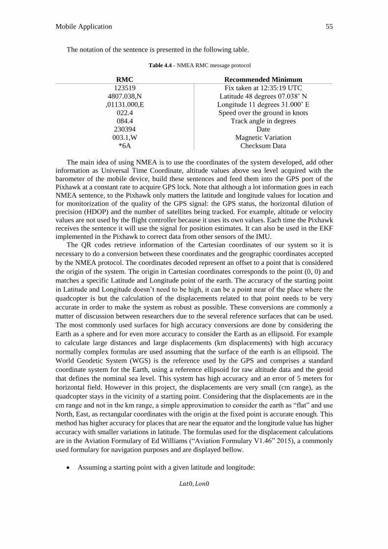
Mobile Application 55
The notation of the sentence is presented in the following table.
Table 4.4 - NMEA RMC message protocol
RMC Recommended Minimum
123519 Fix taken at 12:35:19 UTC
4807.038,N Latitude 48 degrees 07.038’ N
,01131.000,E Longitude 11 degrees 31.000’ E
022.4 Speed over the ground in knots
084.4 Track angle in degrees
230394 Date
003.1,W Magnetic Variation
*6A Checksum Data
The main idea of using NMEA is to use the coordinates of the system developed, add other
information as Universal Time Coordinate, altitude values above sea level acquired with the
barometer of the mobile device, build these sentences and feed them into the GPS port of the
Pixhawk at a constant rate to acquire GPS lock. Note that although a lot information goes in each
NMEA sentence, to the Pixhawk only matters the latitude and longitude values for location and
for monitorization of the quality of the GPS signal: the GPS status, the horizontal dilution of
precision (HDOP) and the number of satellites being tracked. For example, altitude or velocity
values are not used by the flight controller because it uses its own values. Each time the Pixhawk
receives the sentence it will use the signal for position estimates. It can also be used in the EKF
implemented in the Pixhawk to correct data from other sensors of the IMU.
The QR codes retrieve information of the Cartesian coordinates of our system so it is
necessary to do a conversion between these coordinates and the geographic coordinates accepted
by the NMEA protocol. The coordinates decoded represent an offset to a point that is considered
the origin of the system. The origin in Cartesian coordinates corresponds to the point (0, 0) and
matches a specific Latitude and Longitude point of the earth. The accuracy of the starting point
in Latitude and Longitude doesn’t need to be high, it can be a point near of the place where the
quadcopter is but the calculation of the displacements related to that point needs to be very
accurate in order to make the system as robust as possible. These conversions are commonly a
matter of discussion between researchers due to the several reference surfaces that can be used.
The most commonly used surfaces for high accuracy conversions are done by considering the
Earth as a sphere and for even more accuracy to consider the Earth as an ellipsoid. For example
to calculate large distances and large displacements (km displacements) with high accuracy
normally complex formulas are used assuming that the surface of the earth is an ellipsoid. The
World Geodetic System (WGS) is the reference used by the GPS and comprises a standard
coordinate system for the Earth, using a reference ellipsoid for raw altitude data and the geoid
that defines the nominal sea level. This system has high accuracy and an error of 5 meters for
horizontal field. However in this project, the displacements are very small (cm range), as the
quadcopter stays in the vicinity of a starting point. Considering that the displacements are in the
cm range and not in the km range, a simple approximation to consider the earth as “flat” and use
North, East, as rectangular coordinates with the origin at the fixed point is accurate enough. This
method has higher accuracy for places that are near the equator and the longitude value has higher
accuracy with smaller variations in latitude. The formulas used for the displacement calculations
are in the Aviation Formulary of Ed Williams (“Aviation Formulary V1.46” 2015), a commonly
used formulary for navigation purposes and are displayed bellow.
Assuming a starting point with a given latitude and longitude:
𝐿𝑎𝑡0, 𝐿𝑜𝑛0
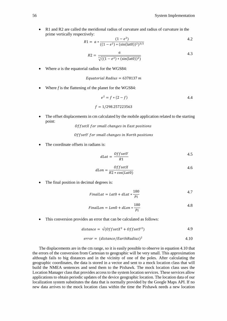
56 System Implementation
R1 and R2 are called the meridional radius of curvature and radius of curvature in the
prime vertically respectively:
𝑅1 = 𝑎 ∗
(1 − 𝑒2)
((1 − 𝑒2) ∗ (sin(lat0))2)3/2
4.2
𝑅2 = 𝑎
√((1 − 𝑒2) ∗ (sin(lat0))2)2
4.3
Where a is the equatorial radius for the WGS84:
𝐸𝑞𝑢𝑎𝑡𝑜𝑟𝑖𝑎𝑙 𝑅𝑎𝑑𝑖𝑢𝑠 = 6378137 𝑚
Where f is the flattening of the planet for the WGS84:
𝑒2 = 𝑓 ∗ (2 − 𝑓)
4.4
𝑓 = 1/298.257223563
The offset displacements in cm calculated by the mobile application related to the starting
point: 𝑂𝑓𝑓𝑠𝑒𝑡𝑋 𝑓𝑜𝑟 𝑠𝑚𝑎𝑙𝑙 𝑐ℎ𝑎𝑛𝑔𝑒𝑠 𝑖𝑛 𝐸𝑎𝑠𝑡 𝑝𝑜𝑠𝑖𝑡𝑖𝑜𝑛𝑠
𝑂𝑓𝑓𝑠𝑒𝑡𝑌 𝑓𝑜𝑟 𝑠𝑚𝑎𝑙𝑙 𝑐ℎ𝑎𝑛𝑔𝑒𝑠 𝑖𝑛 𝑁𝑜𝑟𝑡ℎ 𝑝𝑜𝑠𝑖𝑡𝑖𝑜𝑛𝑠
The coordinate offsets in radians is:
𝑑𝐿𝑎𝑡 =
𝑂𝑓𝑓𝑠𝑒𝑡𝑌
𝑅1
4.5
𝑑𝐿𝑜𝑛 =
𝑂𝑓𝑓𝑠𝑒𝑡𝑋
𝑅2 ∗ cos(𝐿𝑎𝑡0)
4.6
The final position in decimal degrees is:
𝐹𝑖𝑛𝑎𝑙𝐿𝑎𝑡 = 𝐿𝑎𝑡0 + 𝑑𝐿𝑎𝑡 ∗
180
𝑃𝑖
4.7
𝐹𝑖𝑛𝑎𝑙𝐿𝑜𝑛 = 𝐿𝑜𝑛0 + 𝑑𝐿𝑜𝑛 ∗
180
𝑃𝑖
4.8
This conversion provides an error that can be calculated as follows:
𝑑𝑖𝑠𝑡𝑎𝑛𝑐𝑒 = √(𝑂𝑓𝑓𝑠𝑒𝑡𝑋2 + 𝑂𝑓𝑓𝑠𝑒𝑡𝑌2) 4.9
𝑒𝑟𝑟𝑜𝑟 = (𝑑𝑖𝑠𝑡𝑎𝑛𝑐𝑒/𝐸𝑎𝑟𝑡ℎ𝑅𝑎𝑑𝑖𝑢𝑠)2
4.10
The displacements are in the cm range, so it is easily possible to observe in equation 4.10 that
the errors of the conversion from Cartesian to geographic will be very small. This approximation
although fails to big distances and in the vicinity of one of the poles. After calculating the
geographic coordinates, the data is stored in a vector and sent to a mock location class that will
build the NMEA sentences and send them to the Pixhawk. The mock location class uses the
Location Manager class that provides access to the system location services. These services allow
applications to obtain periodic updates of the device geographic location. The location data of our
localization system substitutes the data that is normally provided by the Google Maps API. If no
new data arrives to the mock location class within the time the Pixhawk needs a new location
Mobile Application 57
update, the last information received will be sent. The transmission of NMEA data is done at a
baud rate of 38400 bps at a rate of 5 Hz to the GPS port of the Pixhawk.
4.3.4 MAVLink Integration
MAVLink (“MAVLink Micro Air Vehicle Communication Protocol” 2015) is a
communication protocol for micro air vehicles as the name suggests but also supports ground
robots integration. MAVLink is the protocol used by the Pixhawk to communicate with the
ground station that can be a Mission Planner running on a desktop or a simple Android device.
The MAVLink message is a stream of bytes that has been encoded by the ground control station
and is sent to the Pixhawk to the USB or telemetry port. Usually each MAVLink packet has a
length of 17 bytes and the structure is the following:
6 header bytes, 9 bytes of payload and 2 bytes of error detection.
The header usually has a message header always 0 x FE, the message length, sequence
number, the system ID (what is the system sending the message), component ID (what component
of the system is sending the message) and finally the message ID (what is the content of the
message). The payload can have variable size, it is where the relevant data is. The 2 bytes of error
detection concern the checksum. The Pixhawk checks if the message is valid by verifying the
checksum, if it is corrupted it discards the message. The errors in the message are directly related
to the baud rate, if the baud rate is too high the message is more prone to errors. Usually baud rate
value for the exchange of telemetry data is 57600 bps or 115200 bps.
In the quadcopter side, more specifically in the firmware of the Pixhawk there is a method
called handlemessage (msg) that asks the packet to read the system ID and the component ID to
see if it’s meant for the quadcopter. If so, the payload message is extracted and placed in another
packet. This new packet is a data structure based on an information type as for example orientation
(pitch, roll, yaw orientation). Off all sets of messages, the most important is the heartbeat message:
MAVLink_MSG_ID_HEARTBEAT. The mobile application needs to send this message to the
Pixhawk every second to find weather it’s connected to it or not. This is to make sure that
everything is in sync when it’s necessary to update some parameters. If a number of heartbeats is
missed when flying autonomous mode, a failsafe can be triggered to make the quadcopter RTL
(Return to Launch).
As said before MAVLink is used in this project to allow communication between the on board
mobile device and the Pixhawk. To profit from the fact the firmware of the Pixhawk allows the
creation of missions in the autonomous mode with GPS lock it’s necessary to develop a MAVLink
protocol on the Android side that needs to interpret the messages sent by the Pixhawk. MAVLink
protocol is originally written in C but there are several java open source MAVLink libraries
(“Mavlinkjava ” 2015) that the project can take advantage of. It’s also necessary to use the library
Usb to Serial for Android (“Usb-Serial-for-Android ” 2015) to allow the exchange of messages
between the mobile device and the Pixhawk. This library supports communications between
Arduino and other USB serial hardware on Android using the Android USB host API available
since Android 3.1. Communication is achieved simply by getting a raw serial port with read() and
write() functions without the need of root access, ADK or special kernel drivers.
The autonomous mode of the Arducopter is only to be used in open air environments where
there is a lock of the GPS signal. However with the implementation of this indoor location system
it is possible to take advantage of all the features that the autonomous mode allows but in indoor
environments. Using MAVLink, the application has a way to transfer the information related to
mission planning to the Pixhawk. This obviously takes for granted that in parallel, the application
is sending the NMEA messages at a constant rate that allows the GPS lock. The sequence of
actions that the mobile application follows when receives an input from a sensor with a specified
destination coordinate of the QR Code coordinate system is described next. The mobile device
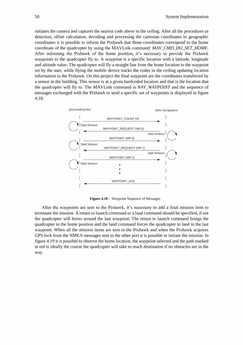
58 System Implementation
initiates the camera and captures the nearest code above in the ceiling. After all the procedures as
detection, offset calculation, decoding and processing the cartesian coordinates to geographic
coordinates it is possible to inform the Pixhawk that those coordinates correspond to the home
coordinate of the quadcopter by using the MAVLink command: MAV_CMD_DO_SET_HOME.
After informing the Pixhawk of the home position, it’s necessary to provide the Pixhawk
waypoints to the quadcopter fly to. A waypoint is a specific location with a latitude, longitude
and altitude value. The quadcopter will fly a straight line from the home location to the waypoint
set by the user, while flying the mobile device tracks the codes in the ceiling updating location
information to the Pixhawk. On this project the final waypoint are the coordinates transferred by
a sensor in the building. This sensor is at a given hardcoded location and that is the location that
the quadcopter will fly to. The MAVLink command is NAV_WAYPOINT and the sequence of
messages exchanged with the Pixhawk to send a specific set of waypoints is displayed in figure
4.18:
Figure 4.18 - Waypoint Sequence of Messages
After the waypoints are sent to the Pixhawk, it’s necessary to add a final mission item to
terminate the mission. A return to launch command or a land command should be specified, if not
the quadcopter will hover around the last waypoint. The return to launch command brings the
quadcopter to the home position and the land command forces the quadcopter to land in the last
waypoint. When all the mission items are sent to the Pixhawk and when the Pixhawk acquires
GPS lock from the NMEA messages sent to the other port it is possible to initiate the mission. In
figure 4.19 it is possible to observe the home location, the waypoint selected and the path marked
at red is ideally the course the quadcopter will take to reach destination if no obstacles are in the
way.
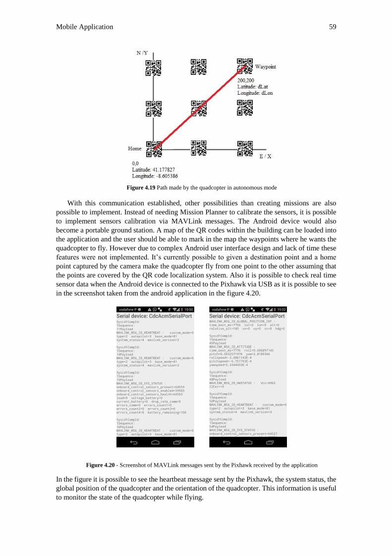
Mobile Application 59
Figure 4.19 Path made by the quadcopter in autonomous mode
With this communication established, other possibilities than creating missions are also
possible to implement. Instead of needing Mission Planner to calibrate the sensors, it is possible
to implement sensors calibration via MAVLink messages. The Android device would also
become a portable ground station. A map of the QR codes within the building can be loaded into
the application and the user should be able to mark in the map the waypoints where he wants the
quadcopter to fly. However due to complex Android user interface design and lack of time these
features were not implemented. It’s currently possible to given a destination point and a home
point captured by the camera make the quadcopter fly from one point to the other assuming that
the points are covered by the QR code localization system. Also it is possible to check real time
sensor data when the Android device is connected to the Pixhawk via USB as it is possible to see
in the screenshot taken from the android application in the figure 4.20.
Figure 4.20 - Screenshot of MAVLink messages sent by the Pixhawk received by the application
In the figure it is possible to see the heartbeat message sent by the Pixhawk, the system status, the
global position of the quadcopter and the orientation of the quadcopter. This information is useful
to monitor the state of the quadcopter while flying.
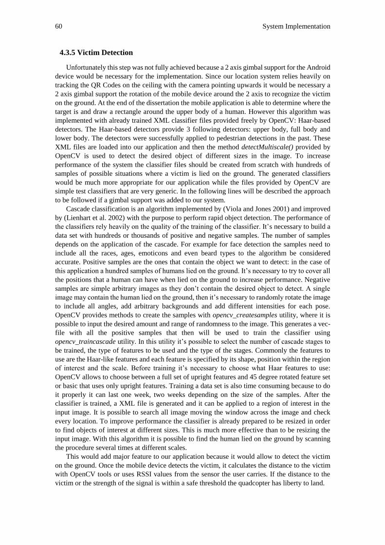
60 System Implementation
4.3.5 Victim Detection
Unfortunately this step was not fully achieved because a 2 axis gimbal support for the Android
device would be necessary for the implementation. Since our location system relies heavily on
tracking the QR Codes on the ceiling with the camera pointing upwards it would be necessary a
2 axis gimbal support the rotation of the mobile device around the 2 axis to recognize the victim
on the ground. At the end of the dissertation the mobile application is able to determine where the
target is and draw a rectangle around the upper body of a human. However this algorithm was
implemented with already trained XML classifier files provided freely by OpenCV: Haar-based
detectors. The Haar-based detectors provide 3 following detectors: upper body, full body and
lower body. The detectors were successfully applied to pedestrian detections in the past. These
XML files are loaded into our application and then the method detectMultiscale() provided by
OpenCV is used to detect the desired object of different sizes in the image. To increase
performance of the system the classifier files should be created from scratch with hundreds of
samples of possible situations where a victim is lied on the ground. The generated classifiers
would be much more appropriate for our application while the files provided by OpenCV are
simple test classifiers that are very generic. In the following lines will be described the approach
to be followed if a gimbal support was added to our system.
Cascade classification is an algorithm implemented by (Viola and Jones 2001) and improved
by (Lienhart et al. 2002) with the purpose to perform rapid object detection. The performance of
the classifiers rely heavily on the quality of the training of the classifier. It’s necessary to build a
data set with hundreds or thousands of positive and negative samples. The number of samples
depends on the application of the cascade. For example for face detection the samples need to
include all the races, ages, emoticons and even beard types to the algorithm be considered
accurate. Positive samples are the ones that contain the object we want to detect: in the case of
this application a hundred samples of humans lied on the ground. It’s necessary to try to cover all
the positions that a human can have when lied on the ground to increase performance. Negative
samples are simple arbitrary images as they don’t contain the desired object to detect. A single
image may contain the human lied on the ground, then it’s necessary to randomly rotate the image
to include all angles, add arbitrary backgrounds and add different intensities for each pose.
OpenCV provides methods to create the samples with opencv_createsamples utility, where it is
possible to input the desired amount and range of randomness to the image. This generates a vec-
file with all the positive samples that then will be used to train the classifier using
opencv_traincascade utility. In this utility it’s possible to select the number of cascade stages to
be trained, the type of features to be used and the type of the stages. Commonly the features to
use are the Haar-like features and each feature is specified by its shape, position within the region
of interest and the scale. Before training it’s necessary to choose what Haar features to use:
OpenCV allows to choose between a full set of upright features and 45 degree rotated feature set
or basic that uses only upright features. Training a data set is also time consuming because to do
it properly it can last one week, two weeks depending on the size of the samples. After the
classifier is trained, a XML file is generated and it can be applied to a region of interest in the
input image. It is possible to search all image moving the window across the image and check
every location. To improve performance the classifier is already prepared to be resized in order
to find objects of interest at different sizes. This is much more effective than to be resizing the
input image. With this algorithm it is possible to find the human lied on the ground by scanning
the procedure several times at different scales.
This would add major feature to our application because it would allow to detect the victim
on the ground. Once the mobile device detects the victim, it calculates the distance to the victim
with OpenCV tools or uses RSSI values from the sensor the user carries. If the distance to the
victim or the strength of the signal is within a safe threshold the quadcopter has liberty to land.
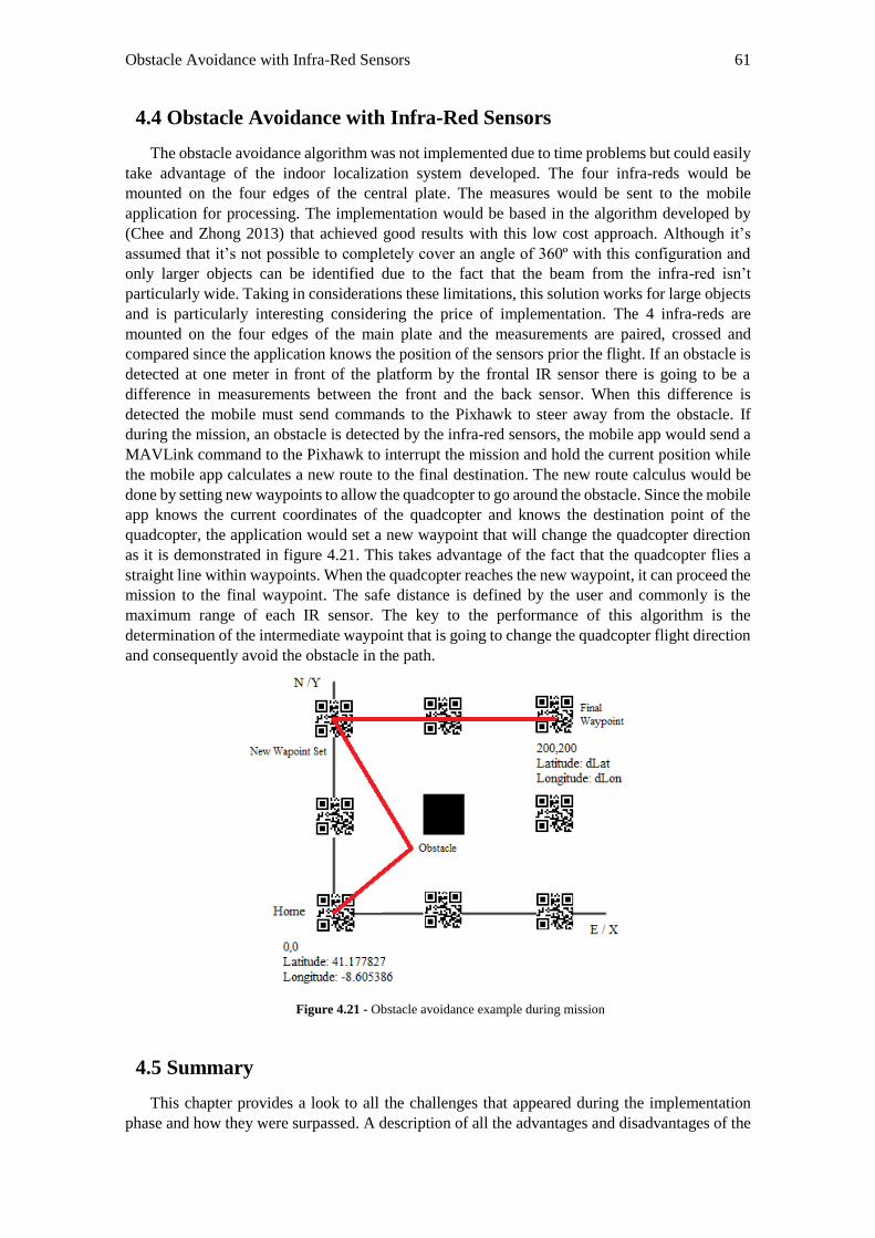
Obstacle Avoidance with Infra-Red Sensors 61
4.4 Obstacle Avoidance with Infra-Red Sensors
The obstacle avoidance algorithm was not implemented due to time problems but could easily
take advantage of the indoor localization system developed. The four infra-reds would be
mounted on the four edges of the central plate. The measures would be sent to the mobile
application for processing. The implementation would be based in the algorithm developed by
(Chee and Zhong 2013) that achieved good results with this low cost approach. Although it’s
assumed that it’s not possible to completely cover an angle of 360º with this configuration and
only larger objects can be identified due to the fact that the beam from the infra-red isn’t
particularly wide. Taking in considerations these limitations, this solution works for large objects
and is particularly interesting considering the price of implementation. The 4 infra-reds are
mounted on the four edges of the main plate and the measurements are paired, crossed and
compared since the application knows the position of the sensors prior the flight. If an obstacle is
detected at one meter in front of the platform by the frontal IR sensor there is going to be a
difference in measurements between the front and the back sensor. When this difference is
detected the mobile must send commands to the Pixhawk to steer away from the obstacle. If
during the mission, an obstacle is detected by the infra-red sensors, the mobile app would send a
MAVLink command to the Pixhawk to interrupt the mission and hold the current position while
the mobile app calculates a new route to the final destination. The new route calculus would be
done by setting new waypoints to allow the quadcopter to go around the obstacle. Since the mobile
app knows the current coordinates of the quadcopter and knows the destination point of the
quadcopter, the application would set a new waypoint that will change the quadcopter direction
as it is demonstrated in figure 4.21. This takes advantage of the fact that the quadcopter flies a
straight line within waypoints. When the quadcopter reaches the new waypoint, it can proceed the
mission to the final waypoint. The safe distance is defined by the user and commonly is the
maximum range of each IR sensor. The key to the performance of this algorithm is the
determination of the intermediate waypoint that is going to change the quadcopter flight direction
and consequently avoid the obstacle in the path.
Figure 4.21 - Obstacle avoidance example during mission
4.5 Summary
This chapter provides a look to all the challenges that appeared during the implementation
phase and how they were surpassed. A description of all the advantages and disadvantages of the
62 System Implementation
implemented system and at every mentioned disadvantage, possible solutions on how to
overcome the problems in a near future.
By order, the section includes: the integration of all hardware modules of this project and how
they are placed on board for the flights. The setup of some modules, namely the Pixhawk with
the calibration of the internal and external sensors. A detailed description of the Android
application and the prepared environment. The communication protocols implemented to
interface with the Pixhawk. Finally a description of how the algorithms of obstacle avoidance and
victim recognition would be implemented to fit the designed system.
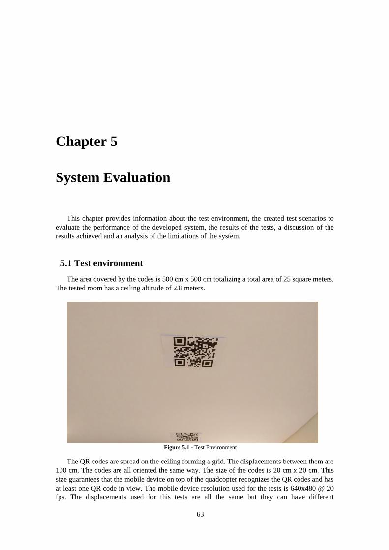
63
Chapter 5
System Evaluation
This chapter provides information about the test environment, the created test scenarios to
evaluate the performance of the developed system, the results of the tests, a discussion of the
results achieved and an analysis of the limitations of the system.
5.1 Test environment
The area covered by the codes is 500 cm x 500 cm totalizing a total area of 25 square meters.
The tested room has a ceiling altitude of 2.8 meters.
Figure 5.1 - Test Environment
The QR codes are spread on the ceiling forming a grid. The displacements between them are
100 cm. The codes are all oriented the same way. The size of the codes is 20 cm x 20 cm. This
size guarantees that the mobile device on top of the quadcopter recognizes the QR codes and has
at least one QR code in view. The mobile device resolution used for the tests is 640x480 @ 20
fps. The displacements used for this tests are all the same but they can have different
64 System Evaluation
displacements from of each other as long as the QR codes provide their absolute location and are
orientated the same way. For example in indoor environments with several divisions different
displacements are almost obligatory to allow the quadcopter to fly from one division to the next.
5.2 Test Cases
To examine the functionalities of the setup developed, the following tests were performed.
5.2.1 Computer Vision Evaluation
The computer vision tests evaluate the performance of the vision algorithms implemented in
this dissertation. The evaluation consists in the attempt to detect and decode the QR code from
different ranges, views, orientations, light conditions and with different type of speed movements
of the smartphone. The integrated victim detection algorithm is also evaluated in this section. The
computer vision evaluation tests were performed outside of the quadcopter because it’s important
to do the tests with real precise measures and that would not be possible if the smartphone was
on board of the quadcopter due to the constant movement. Almost all the tests were performed
with the mobile device in a tripod to allow real precise measures to evaluate the system. The
exception is the speed movement test since it is important to verify if the application is robust
enough to decode a QR code while the smartphone is moving thus simulating the conditions on
board of the quadcopter. The following tests are performed:
-QR Code detection - Test if it is possible to detect the code from different ranges, different
QR code orientations, from perpendicular and oblique views, different light conditions and
different types of speed movements by the mobile device.
-QR Code decode - Test if it possible for each detection, to decode the QR code from different
ranges, different QR code orientations, from perpendicular and oblique views, different light
conditions and different types of movements by the mobile device.
-Measure distance to the code error of the system - Evaluate the distance to the code error
of the system using real precise measures. With the mobile device placed at a known distance to
the code, compare the real results with the results computed by the system.
-Victim detection - Evaluate the detection of a user in several positions on the ground. It is
presented results for the detectors used: Haar detectors. To get benchmark results for the use of
this detector like the hit rate or the number of false positives in an image it would be necessary to
run the detectors over a recorded video sequence with the victims partially occluded by objects
and analyze the performance. Since there wasn’t a gimbal on board to allow the rotation of the
mobile device and to capture video data of the victims on the ground it wasn’t tested the
application of these detectors to the dissertation. Since the quadcopter it’s not fully stable it will
also be dangerous to attempt detection from the quadcopter. What was done was a simple
recording by hand and test if the detectors are able to detect the victim on several positions and
lied on two distinct backgrounds from a 2 meter distance.
5.2.2 Flight Stability
The flight stability tests evaluates if the quadcopter is able to receive the NMEA data
accordingly for position and orientation estimation. This allows to evaluate the quality of our GPS
signal. Also, altitude hold using the sonar sensor is evaluated. The flight stability tests are the
most important requirements to provide a robust and autonomous flight.
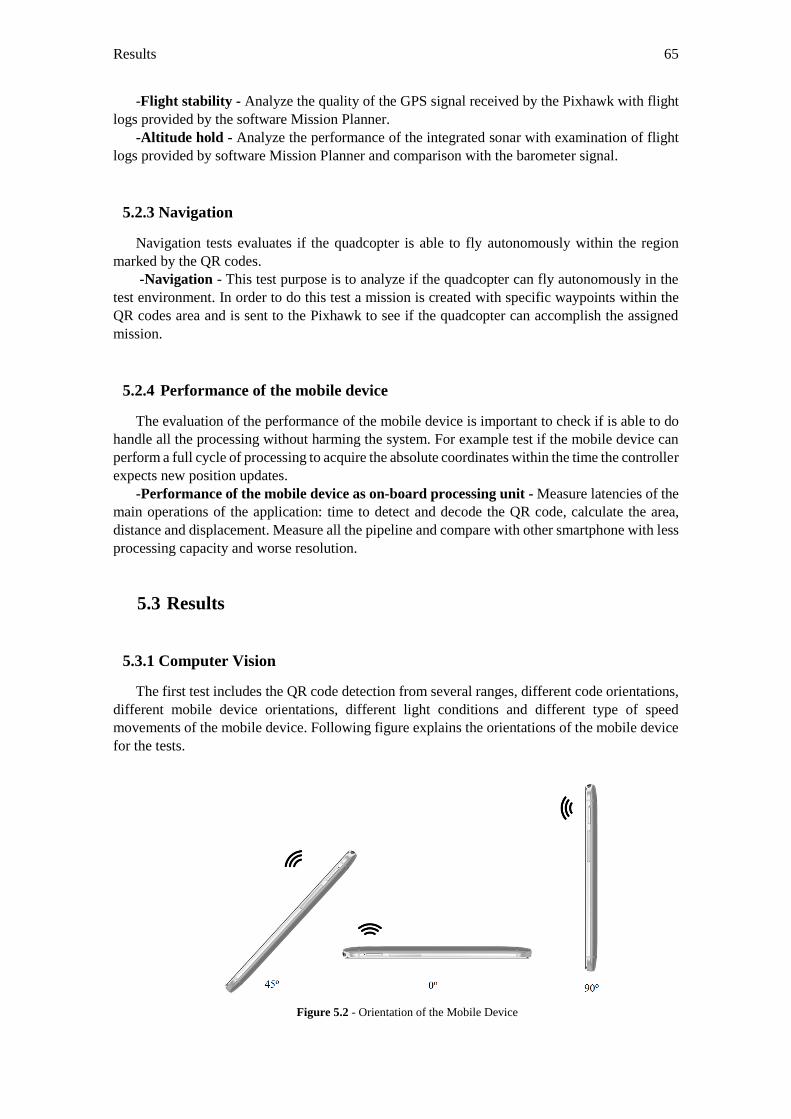
Results 65
-Flight stability - Analyze the quality of the GPS signal received by the Pixhawk with flight
logs provided by the software Mission Planner.
-Altitude hold - Analyze the performance of the integrated sonar with examination of flight
logs provided by software Mission Planner and comparison with the barometer signal.
5.2.3 Navigation
Navigation tests evaluates if the quadcopter is able to fly autonomously within the region
marked by the QR codes.
-Navigation - This test purpose is to analyze if the quadcopter can fly autonomously in the
test environment. In order to do this test a mission is created with specific waypoints within the
QR codes area and is sent to the Pixhawk to see if the quadcopter can accomplish the assigned
mission.
5.2.4 Performance of the mobile device
The evaluation of the performance of the mobile device is important to check if is able to do
handle all the processing without harming the system. For example test if the mobile device can
perform a full cycle of processing to acquire the absolute coordinates within the time the controller
expects new position updates.
-Performance of the mobile device as on-board processing unit - Measure latencies of the
main operations of the application: time to detect and decode the QR code, calculate the area,
distance and displacement. Measure all the pipeline and compare with other smartphone with less
processing capacity and worse resolution.
5.3 Results
5.3.1 Computer Vision
The first test includes the QR code detection from several ranges, different code orientations,
different mobile device orientations, different light conditions and different type of speed
movements of the mobile device. Following figure explains the orientations of the mobile device
for the tests.
Figure 5.2 - Orientation of the Mobile Device
66 System Evaluation
To test the detection of the QR code from several ranges it was selected a QR code with a size
of 20x20cm. The mobile device is placed right under the code, with the code centered in the
frame, the QR code orientation is 0º and completely static, only the smartphone moves to
increase the distance between them.
Table 5.1 – Detection for several distances
Distance (cm) Test Result
50 Detected
100 Detected
200 Detected
250 Detected
300 Not Detected
To verify that it is possible to detect the code for all possible orientations, the mobile device was
placed at 100 cm from under the code and then the code was rotated to all 4 possible orientations
with the mobile device static.
Table 5.2 - Detection for several code orientations
Distance (cm) 100
Orientation of the Code Test Result
North Detected
South Detected
East Detected
West Detected
Next test goal is to change the angle from what the smartphone views the code. It’s necessary to
evaluate if it is possible to detect with an oblique view. The orientation of the mobile device
changes and the code is placed at 0º degrees. Since when the mobile device is oriented 90º it is
impossible to detect any code, the tests were performed from 0º to 60º.
Table 5.3 - Detection for several mobile device orientations
Distance (cm) 100
Orientation of the Mobile
Device
Test Result
0º Detected
30º Detected
45º Detected
60º Detected
Next test goal is to try to detect the code with the environment having three different illumination
conditions: bright, medium and dark.
Table 5.4 - Detection for several light conditions
Distance (cm) 100
Light Condition Test Result
Bright Detected
Medium Detected
Dark Detected
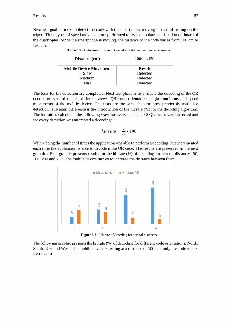
Results 67
Next test goal is to try to detect the code with the smartphone moving instead of resting on the
tripod. Three types of speed movement are performed to try to simulate the situation on-board of
the quadcopter. Since the smartphone is moving, the distance to the code varies from 100 cm to
150 cm. Table 5.5 - Detection for several type of mobile device speed movements
Distance (cm) 100<d<150
Mobile Device Movement Result
Slow Detected
Medium Detected
Fast Detected
The tests for the detection are completed. Next test phase is to evaluate the decoding of the QR
code from several ranges, different views, QR code orientations, light conditions and speed
movements of the mobile device. The tests are the same that the ones previously made for
detection. The main difference is the introduction of the hit rate (%) for the decoding algorithm.
The hit rate is calculated the following way: for every distance, 50 QR codes were detected and
for every detection was attempted a decoding:
ℎ𝑖𝑡 𝑟𝑎𝑡𝑒 =𝑥
50∗ 100
With x being the number of times the application was able to perform a decoding. It is incremented
each time the application is able to decode it the QR code. The results are presented in the next
graphics. First graphic presents results for the hit rate (%) of decoding for several distances: 50,
100, 200 and 250. The mobile device moves to increase the distance between them.
Figure 5.3 - Hit rate of decoding for several distances
The following graphic presents the hit rate (%) of decoding for different code orientations: North,
South, East and West. The mobile device is resting at a distance of 100 cm, only the code rotates
for this test.
50
10
0
20
0
25
0
98
82
44
34
1 2 3 4
Distance (cm) Hit Rate (%)
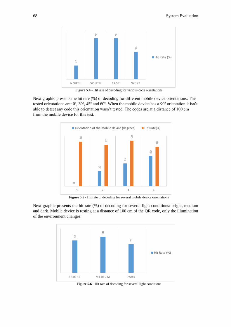
68 System Evaluation
Figure 5.4 - Hit rate of decoding for various code orientations
Next graphic presents the hit rate (%) of decoding for different mobile device orientations. The
tested orientations are: 0º, 30º, 45º and 60º. When the mobile device has a 90º orientation it isn’t
able to detect any code this orientation wasn’t tested. The codes are at a distance of 100 cm
from the mobile device for this test.
Figure 5.5 - Hit rate of decoding for several mobile device orientations
Next graphic presents the hit rate (%) of decoding for several light conditions: bright, medium
and dark. Mobile device is resting at a distance of 100 cm of the QR code, only the illumination
of the environment changes.
Figure 5.6 - Hit rate of decoding for several light conditions
92
96
96
94
N O R T H S O U T H E A S T W E S T
Hit Rate (%)
0
30
45
60
88
82
90
78
1 2 3 4
Orientation of the mobile device (degrees) Hit Rate(%)
88
98
78
B R I G H T M E D I U M D A R K
Hit Rate (%)
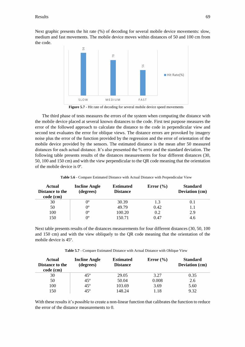
Results 69
Next graphic presents the hit rate (%) of decoding for several mobile device movements: slow,
medium and fast movements. The mobile device moves within distances of 50 and 100 cm from
the code.
Figure 5.7 - Hit rate of decoding for several mobile device speed movements
The third phase of tests measures the errors of the system when computing the distance with
the mobile device placed at several known distances to the code. First test purpose measures the
error of the followed approach to calculate the distance to the code in perpendicular view and
second test evaluates the error for oblique views. The distance errors are provoked by imagery
noise plus the error of the function provided by the regression and the error of orientation of the
mobile device provided by the sensors. The estimated distance is the mean after 50 measured
distances for each actual distance. It’s also presented the % error and the standard deviation. The
following table presents results of the distances measurements for four different distances (30,
50, 100 and 150 cm) and with the view perpendicular to the QR code meaning that the orientation
of the mobile device is 0º.
Table 5.6 - Compare Estimated Distance with Actual Distance with Perpendicular View
Actual
Distance to the
code (cm)
Incline Angle
(degrees)
Estimated
Distance
Error (%) Standard
Deviation (cm)
30 0º 30.39 1.3 0.1
50 0º 49.79 0.42 1.1
100 0º 100.20 0.2 2.9
150 0º 150.71 0.47 4.6
Next table presents results of the distances measurements for four different distances (30, 50, 100
and 150 cm) and with the view obliquely to the QR code meaning that the orientation of the
mobile device is 45º.
Table 5.7 - Compare Estimated Distance with Actual Distance with Oblique View
Actual
Distance to the
code (cm)
Incline Angle
(degrees)
Estimated
Distance
Error (%) Standard
Deviation (cm)
30 45º 29.05 3.27 0.35
50 45º 50.04 0.008 2.6
100 45º 103.69 3.69 5.60
150 45º 148.24 1.18 9.32
With these results it’s possible to create a non-linear function that calibrates the function to reduce
the error of the distance measurements to 0.
94
78
56
S L O W M E D I U M F A S T
Hit Rate(%)
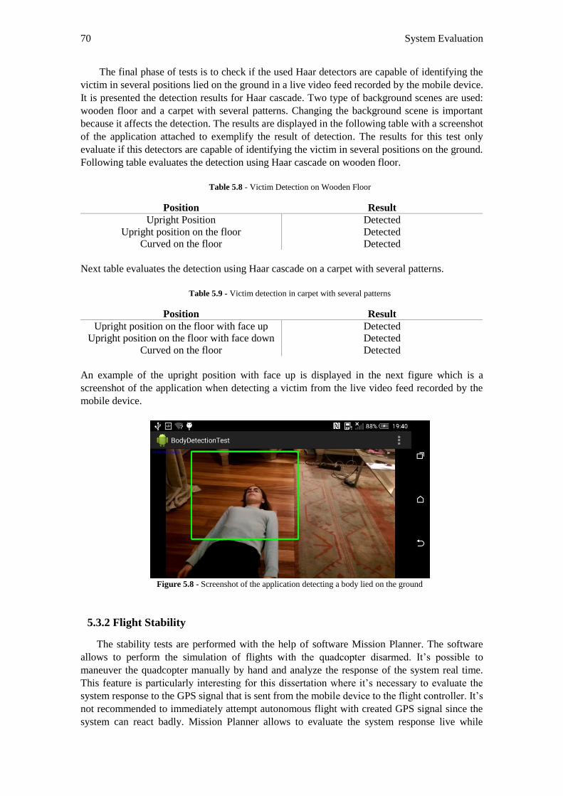
70 System Evaluation
The final phase of tests is to check if the used Haar detectors are capable of identifying the
victim in several positions lied on the ground in a live video feed recorded by the mobile device.
It is presented the detection results for Haar cascade. Two type of background scenes are used:
wooden floor and a carpet with several patterns. Changing the background scene is important
because it affects the detection. The results are displayed in the following table with a screenshot
of the application attached to exemplify the result of detection. The results for this test only
evaluate if this detectors are capable of identifying the victim in several positions on the ground.
Following table evaluates the detection using Haar cascade on wooden floor.
Table 5.8 - Victim Detection on Wooden Floor
Position Result
Upright Position Detected
Upright position on the floor Detected
Curved on the floor Detected
Next table evaluates the detection using Haar cascade on a carpet with several patterns.
Table 5.9 - Victim detection in carpet with several patterns
Position Result
Upright position on the floor with face up Detected
Upright position on the floor with face down Detected
Curved on the floor Detected
An example of the upright position with face up is displayed in the next figure which is a
screenshot of the application when detecting a victim from the live video feed recorded by the
mobile device.
Figure 5.8 - Screenshot of the application detecting a body lied on the ground
5.3.2 Flight Stability
The stability tests are performed with the help of software Mission Planner. The software
allows to perform the simulation of flights with the quadcopter disarmed. It’s possible to
maneuver the quadcopter manually by hand and analyze the response of the system real time.
This feature is particularly interesting for this dissertation where it’s necessary to evaluate the
system response to the GPS signal that is sent from the mobile device to the flight controller. It’s
not recommended to immediately attempt autonomous flight with created GPS signal since the
system can react badly. Mission Planner allows to evaluate the system response live while
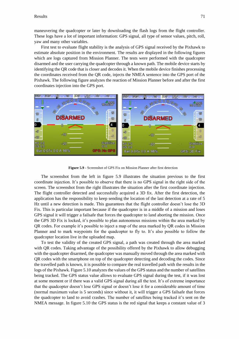
Results 71
maneuvering the quadcopter or later by downloading the flash logs from the flight controller.
These logs have a lot of important information: GPS signal, all type of sensor values, pitch, roll,
yaw and many other variables.
First test to evaluate flight stability is the analysis of GPS signal received by the Pixhawk to
estimate absolute position in the environment. The results are displayed in the following figures
which are logs captured from Mission Planner. The tests were performed with the quadcopter
disarmed and the user carrying the quadcopter through a known path. The mobile device starts by
identifying the QR code that is closer and decodes it. When the mobile device finishes processing
the coordinates received from the QR code, injects the NMEA sentence into the GPS port of the
Pixhawk. The following figure analyzes the reaction of Mission Planner before and after the first
coordinates injection into the GPS port.
Figure 5.9 - Screenshot of GPS Fix on Mission Planner after first detection
The screenshot from the left in figure 5.9 illustrates the situation previous to the first
coordinate injection. It’s possible to observe that there is no GPS signal in the right side of the
screen. The screenshot from the right illustrates the situation after the first coordinate injection.
The flight controller detected and successfully acquired a 3D fix. After the first detection, the
application has the responsibility to keep sending the location of the last detection at a rate of 5
Hz until a new detection is made. This guarantees that the flight controller doesn’t lose the 3D
Fix. This is particular important because if the quadcopter is in a middle of a mission and loses
GPS signal it will trigger a failsafe that forces the quadcopter to land aborting the mission. Once
the GPS 3D Fix is locked, it’s possible to plan autonomous missions within the area marked by
QR codes. For example it’s possible to inject a map of the area marked by QR codes in Mission
Planner and to mark waypoints for the quadcopter to fly to. It’s also possible to follow the
quadcopter location live in the uploaded map.
To test the validity of the created GPS signal, a path was created through the area marked
with QR codes. Taking advantage of the possibility offered by the Pixhawk to allow debugging
with the quadcopter disarmed, the quadcopter was manually moved through the area marked with
QR codes with the smartphone on top of the quadcopter detecting and decoding the codes. Since
the travelled path is known, it is possible to compare the real travelled path with the results in the
logs of the Pixhawk. Figure 5.10 analyzes the values of the GPS status and the number of satellites
being tracked. The GPS status value allows to evaluate GPS signal during the test, if it was lost
at some moment or if there was a valid GPS signal during all the test. It’s of extreme importance
that the quadcopter doesn’t lose GPS signal or doesn’t lose it for a considerable amount of time
(normal maximum value is 5 seconds) since without it, it will trigger a GPS failsafe that forces
the quadcopter to land to avoid crashes. The number of satellites being tracked it’s sent on the
NMEA message. In figure 5.10 the GPS status is the red signal that keeps a constant value of 3
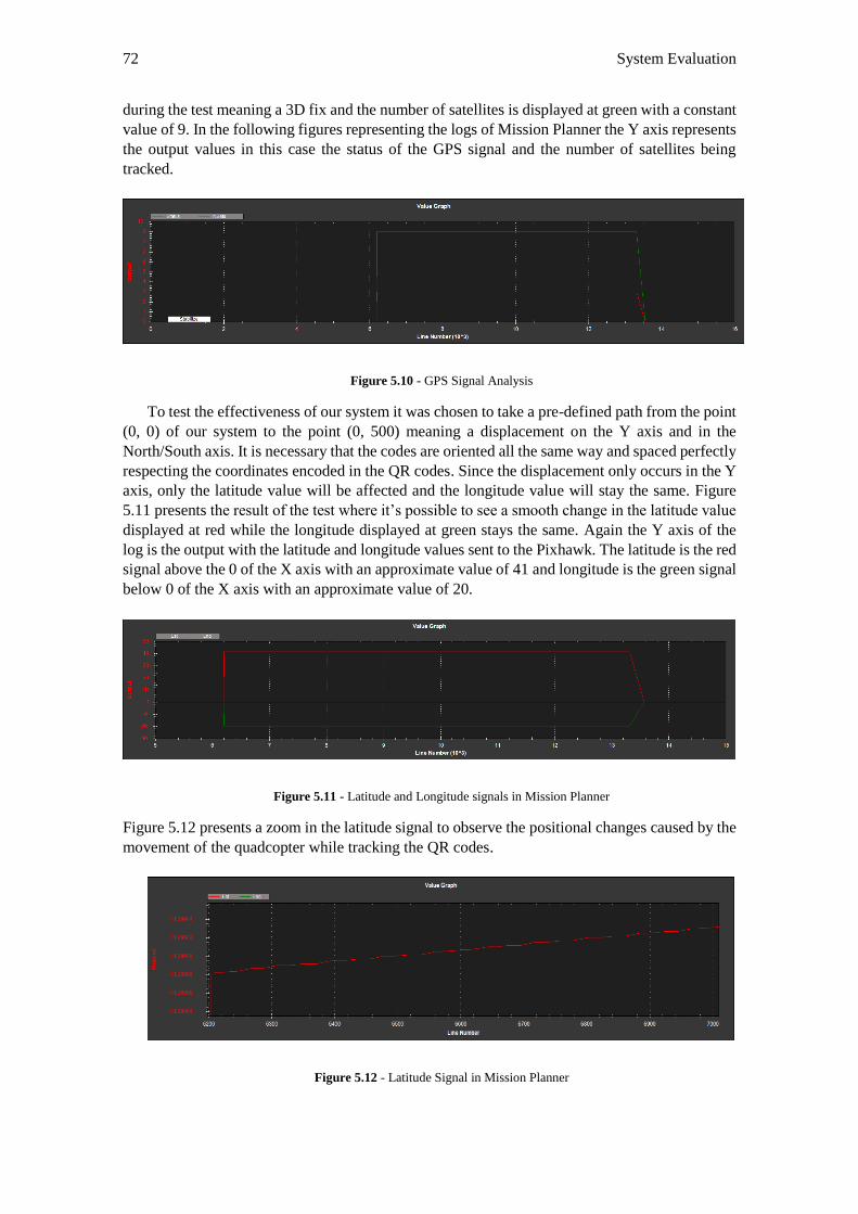
72 System Evaluation
during the test meaning a 3D fix and the number of satellites is displayed at green with a constant
value of 9. In the following figures representing the logs of Mission Planner the Y axis represents
the output values in this case the status of the GPS signal and the number of satellites being
tracked.
Figure 5.10 - GPS Signal Analysis
To test the effectiveness of our system it was chosen to take a pre-defined path from the point
(0, 0) of our system to the point (0, 500) meaning a displacement on the Y axis and in the
North/South axis. It is necessary that the codes are oriented all the same way and spaced perfectly
respecting the coordinates encoded in the QR codes. Since the displacement only occurs in the Y
axis, only the latitude value will be affected and the longitude value will stay the same. Figure
5.11 presents the result of the test where it’s possible to see a smooth change in the latitude value
displayed at red while the longitude displayed at green stays the same. Again the Y axis of the
log is the output with the latitude and longitude values sent to the Pixhawk. The latitude is the red
signal above the 0 of the X axis with an approximate value of 41 and longitude is the green signal
below 0 of the X axis with an approximate value of 20.
Figure 5.11 - Latitude and Longitude signals in Mission Planner
Figure 5.12 presents a zoom in the latitude signal to observe the positional changes caused by the
movement of the quadcopter while tracking the QR codes.
Figure 5.12 - Latitude Signal in Mission Planner
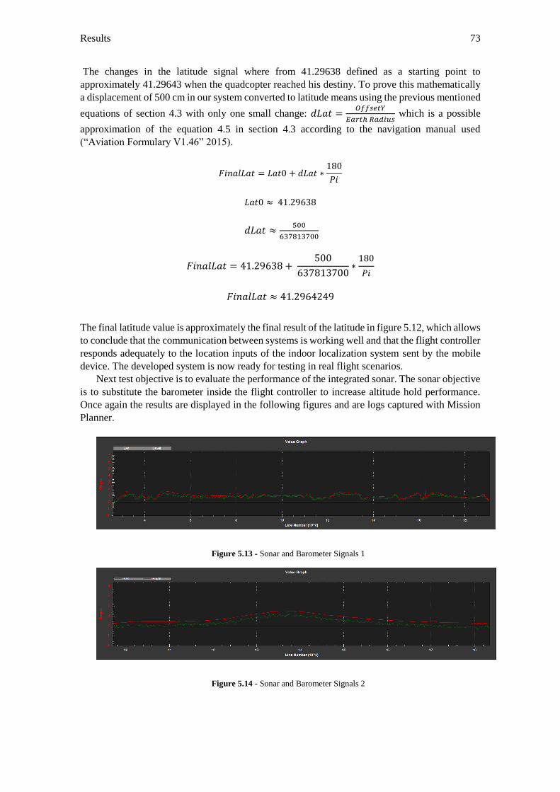
Results 73
The changes in the latitude signal where from 41.29638 defined as a starting point to
approximately 41.29643 when the quadcopter reached his destiny. To prove this mathematically
a displacement of 500 cm in our system converted to latitude means using the previous mentioned
equations of section 4.3 with only one small change: 𝑑𝐿𝑎𝑡 =𝑂𝑓𝑓𝑠𝑒𝑡𝑌
𝐸𝑎𝑟𝑡ℎ 𝑅𝑎𝑑𝑖𝑢𝑠 which is a possible
approximation of the equation 4.5 in section 4.3 according to the navigation manual used
(“Aviation Formulary V1.46” 2015).
𝐹𝑖𝑛𝑎𝑙𝐿𝑎𝑡 = 𝐿𝑎𝑡0 + 𝑑𝐿𝑎𝑡 ∗180
𝑃𝑖
𝐿𝑎𝑡0 ≈ 41.29638
𝑑𝐿𝑎𝑡 ≈500
637813700
𝐹𝑖𝑛𝑎𝑙𝐿𝑎𝑡 = 41.29638 + 500
637813700∗
180
𝑃𝑖
𝐹𝑖𝑛𝑎𝑙𝐿𝑎𝑡 ≈ 41.2964249
The final latitude value is approximately the final result of the latitude in figure 5.12, which allows
to conclude that the communication between systems is working well and that the flight controller
responds adequately to the location inputs of the indoor localization system sent by the mobile
device. The developed system is now ready for testing in real flight scenarios.
Next test objective is to evaluate the performance of the integrated sonar. The sonar objective
is to substitute the barometer inside the flight controller to increase altitude hold performance.
Once again the results are displayed in the following figures and are logs captured with Mission
Planner.
Figure 5.13 - Sonar and Barometer Signals 1
Figure 5.14 - Sonar and Barometer Signals 2
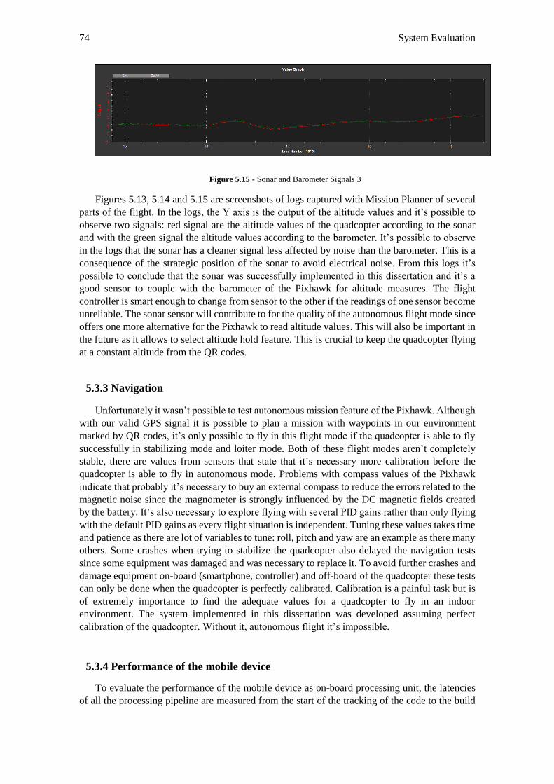
74 System Evaluation
Figure 5.15 - Sonar and Barometer Signals 3
Figures 5.13, 5.14 and 5.15 are screenshots of logs captured with Mission Planner of several
parts of the flight. In the logs, the Y axis is the output of the altitude values and it’s possible to
observe two signals: red signal are the altitude values of the quadcopter according to the sonar
and with the green signal the altitude values according to the barometer. It’s possible to observe
in the logs that the sonar has a cleaner signal less affected by noise than the barometer. This is a
consequence of the strategic position of the sonar to avoid electrical noise. From this logs it’s
possible to conclude that the sonar was successfully implemented in this dissertation and it’s a
good sensor to couple with the barometer of the Pixhawk for altitude measures. The flight
controller is smart enough to change from sensor to the other if the readings of one sensor become
unreliable. The sonar sensor will contribute to for the quality of the autonomous flight mode since
offers one more alternative for the Pixhawk to read altitude values. This will also be important in
the future as it allows to select altitude hold feature. This is crucial to keep the quadcopter flying
at a constant altitude from the QR codes.
5.3.3 Navigation
Unfortunately it wasn’t possible to test autonomous mission feature of the Pixhawk. Although
with our valid GPS signal it is possible to plan a mission with waypoints in our environment
marked by QR codes, it’s only possible to fly in this flight mode if the quadcopter is able to fly
successfully in stabilizing mode and loiter mode. Both of these flight modes aren’t completely
stable, there are values from sensors that state that it’s necessary more calibration before the
quadcopter is able to fly in autonomous mode. Problems with compass values of the Pixhawk
indicate that probably it’s necessary to buy an external compass to reduce the errors related to the
magnetic noise since the magnometer is strongly influenced by the DC magnetic fields created
by the battery. It’s also necessary to explore flying with several PID gains rather than only flying
with the default PID gains as every flight situation is independent. Tuning these values takes time
and patience as there are lot of variables to tune: roll, pitch and yaw are an example as there many
others. Some crashes when trying to stabilize the quadcopter also delayed the navigation tests
since some equipment was damaged and was necessary to replace it. To avoid further crashes and
damage equipment on-board (smartphone, controller) and off-board of the quadcopter these tests
can only be done when the quadcopter is perfectly calibrated. Calibration is a painful task but is
of extremely importance to find the adequate values for a quadcopter to fly in an indoor
environment. The system implemented in this dissertation was developed assuming perfect
calibration of the quadcopter. Without it, autonomous flight it’s impossible.
5.3.4 Performance of the mobile device
To evaluate the performance of the mobile device as on-board processing unit, the latencies
of all the processing pipeline are measured from the start of the tracking of the code to the build
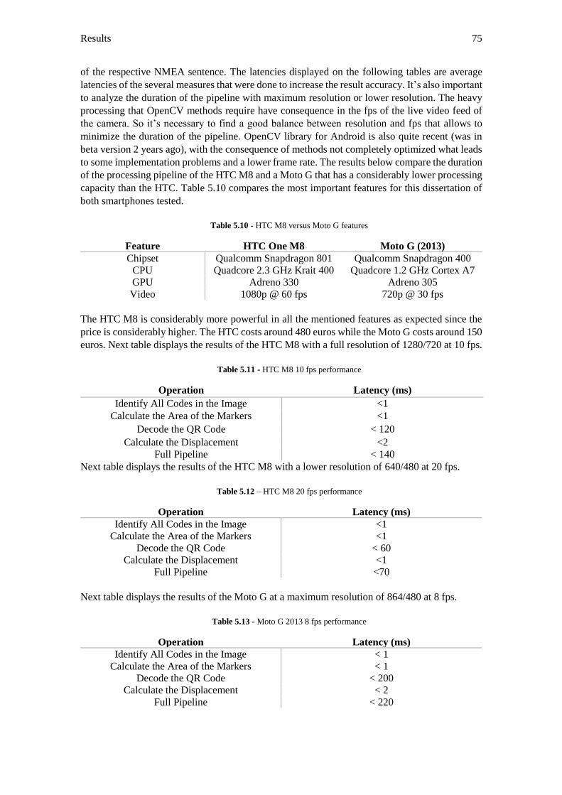
Results 75
of the respective NMEA sentence. The latencies displayed on the following tables are average
latencies of the several measures that were done to increase the result accuracy. It’s also important
to analyze the duration of the pipeline with maximum resolution or lower resolution. The heavy
processing that OpenCV methods require have consequence in the fps of the live video feed of
the camera. So it’s necessary to find a good balance between resolution and fps that allows to
minimize the duration of the pipeline. OpenCV library for Android is also quite recent (was in
beta version 2 years ago), with the consequence of methods not completely optimized what leads
to some implementation problems and a lower frame rate. The results below compare the duration
of the processing pipeline of the HTC M8 and a Moto G that has a considerably lower processing
capacity than the HTC. Table 5.10 compares the most important features for this dissertation of
both smartphones tested.
Table 5.10 - HTC M8 versus Moto G features
Feature HTC One M8 Moto G (2013)
Chipset Qualcomm Snapdragon 801 Qualcomm Snapdragon 400
CPU Quadcore 2.3 GHz Krait 400 Quadcore 1.2 GHz Cortex A7
GPU Adreno 330 Adreno 305
Video 1080p @ 60 fps 720p @ 30 fps
The HTC M8 is considerably more powerful in all the mentioned features as expected since the
price is considerably higher. The HTC costs around 480 euros while the Moto G costs around 150
euros. Next table displays the results of the HTC M8 with a full resolution of 1280/720 at 10 fps.
Table 5.11 - HTC M8 10 fps performance
Operation Latency (ms)
Identify All Codes in the Image <1
Calculate the Area of the Markers <1
Decode the QR Code < 120
Calculate the Displacement <2
Full Pipeline < 140
Next table displays the results of the HTC M8 with a lower resolution of 640/480 at 20 fps.
Table 5.12 – HTC M8 20 fps performance
Operation Latency (ms)
Identify All Codes in the Image <1
Calculate the Area of the Markers <1
Decode the QR Code < 60
Calculate the Displacement <1
Full Pipeline <70
Next table displays the results of the Moto G at a maximum resolution of 864/480 at 8 fps.
Table 5.13 - Moto G 2013 8 fps performance
Operation Latency (ms)
Identify All Codes in the Image < 1
Calculate the Area of the Markers < 1
Decode the QR Code < 200
Calculate the Displacement < 2
Full Pipeline < 220
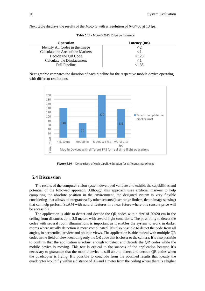
76 System Evaluation
Next table displays the results of the Moto G with a resolution of 640/480 at 13 fps.
Table 5.14 - Moto G 2013 13 fps performance
Operation Latency (ms)
Identify All Codes in the Image < 2
Calculate the Area of the Markers < 1
Decode the QR Code < 125
Calculate the Displacement < 1
Full Pipeline < 135
Next graphic compares the duration of each pipeline for the respective mobile device operating
with different resolutions.
Figure 5.16 – Comparison of each pipeline duration for different smartphones
5.4 Discussion
The results of the computer vision system developed validate and exhibit the capabilities and
potential of the followed approach. Although this approach uses artificial markers to help
computing the absolute position in the environment, the designed system is very flexible
considering that allows to integrate easily other sensors (laser range finders, depth image sensing)
that can help perform SLAM with natural features in a near future where this sensors price will
be accessible.
The application is able to detect and decode the QR codes with a size of 20x20 cm in the
ceiling from distances up to 2.5 meters with several light conditions. The possibility to detect the
codes with several room illuminations is important as it enables the system to work in darker
rooms where usually detection is more complicated. It’s also possible to detect the code from all
angles, in perpendicular view and oblique views. The application is able to deal with multiple QR
codes in the field of view, decoding only the QR code that is closer to the camera. It’s also possible
to confirm that the application is robust enough to detect and decode the QR codes while the
mobile device is moving. This test is critical to the success of the application because it’s
necessary to guarantee that the mobile device is still able to detect and decode QR codes when
the quadcopter is flying. It’s possible to conclude from the obtained results that ideally the
quadcopter would fly within a distance of 0.5 and 1 meter from the ceiling where there is a higher
140
70
220
135
0
20
40
60
80
100
120
140
160
180
200
HTC 10 fps HTC 20 fps MOTO G 8 fps MOTO G 13fps
Tim
e (m
s)
Mobile Devices with different FPS for real time flight operations
Time to complete thepipeline (ms)
Discussion 77
efficiency in decoding. The efficiency decreases with the distance and with the speed movement
of the mobile device. When the smartphone is moving really fast, there’s only 56% of efficiency.
The decoding library worked well under several light conditions enabling the system to work in
darker rooms. Although these results are satisfying, other libraries to decode the QR codes should
be used and compared with the Zxing libraries to see if it possible to decrease the time of the
decoding and increase the hit rate detection for the tested situations. The positive results are also
sustained by the results of the performance of the mobile device. When operating with a resolution
of 640/480 @ 20 fps is able to complete the full pipeline in less than 70 ms. This duration is
sufficient to compute new locations since the Pixhawk only needs position updates in intervals of
200 ms. A similar project that used a similar mobile device to track markers on the ground
performed a full pipeline for location updates in 25 ms (Leichtfried et al. 2013). The difference
from the other project pipeline to ours is that this project pipeline is affected by the decoding of
the QR code that takes around 50 ms to decode after the detection. After consulting the tables
related to the performance of mobile devices it’s possible to take conclusions of the operations
that consume more time. Off all operations, the most time consumer is the decoding of the code
with Zxing libraries reinforcing the need of exploring other libraries to decode the QR code. Other
operations that use OpenCV methods are considerably faster when operating with a lower
resolution. To maximize efficiency it isn’t possible to run the application with a full resolution.
With a full resolution of 1280x720 the number of fps is considerably low for real time flight
operations. Best results in this dissertation were obtained when operating with a resolution
640x480 @ 20 fps. Downgrading the resolution allows the increase of fps as the effort from the
GPU decreases. Other similar project where the QR code detection and decoding was important
for the route of a ground robot used a professional HD camera with a maximum resolution of
1280x730 at 30 fps but were only able to use 640x480 at 10 fps (Suriyon, Keisuke, and Choompol
2011). This allows to conclude that this project is a step forward when compared to similar
projects that used QR codes help in navigation tasks.
The application achieved impressive results when measuring the distance to the QR code in
both perpendicular and oblique views with an accuracy up to 10 cm till 150 cm distances. This is
important as it is the major cause of errors for the final displacement of the quadcopter. The values
will certainly be worse when the mobile device is on board of the quadcopter because it will be
in constant movement, image distortion and errors of mobile device sensors will be higher. The
errors related to distance measurements are caused by noise imagery, power regression function
error and smartphone sensors error. With cm accuracy, the quadcopter is able to fly in tight
environments like corridors or pass through doors where it’s necessary increased positional
accuracy.
Although the victim detection algorithm implemented in the application used already trained
XML files, they have proven to be useful to this particular situation. In the future when a 2D
gimbal is available, it’s important to make a live video feed to analyze properly the use of these
detectors for this application. The results of this experience only allowed to conclude that these
detectors are capable of detecting a victim on the ground and can be evaluated in a near future.
It’s possible to notice in figure 5.8, a screenshot of the live video feed done by hand that the
detections containing the target do not sit on the body but also include some of the background.
This is on purpose since the detection uses some of the background to guarantee proper silhouette
representation. The detectors performed well under the resolution used which is important
because it means that it is possible to downgrade the resolution to allow more fps and continue to
be able to detect the victim.
The tests performed with the quadcopter moving manually, with the mobile device tracking
QR codes and sending the coordinates to the flight controller had good results since the Pixhawk
responded correctly to the performed tested path without losing the GPS signal as it was possible
to observe in Mission Planner flight logs. This enables our system for training tests with the
quadcopter actually flying in autonomous mode. From the logs it was also possible to prove that
78 System Evaluation
the communication between both systems works as expected. Sonar tests also had good results
showing less noise than the barometer in the flight logs provided by Mission Planner, enabling
the sonar for altitude hold purposes in the autonomous flight mode.
With a robust victim detection algorithm with our trained files and an obstacle avoidance
algorithm running on board, this system is capable of performing surveillance in indoor
environments where the GPS signal does not exist. This approach when compared to others brings
several advantages because it doesn’t require expensive hardware boards to compute the results
or professional cameras to capture visual information. The mobile device already has a camera, a
processor, sensors and communications unit combined in one small size system.
5.5 Limitations
The followed approach has limitations because it isn’t able to perform autonomous navigation
using natural features. It’s necessary to use a pre conditioned environment with artificial markers
on the ceiling. The use of QR codes in the ceiling is quite limitative because it brings visual
pollution. While this isn’t meaningful if the purpose of the application is to fly in big warehouses,
in family home environments the use of QR codes in the ceiling to help the quadcopter estimate
position isn’t certainly an option. However this was a step forward to the final objective that is to
perform SLAM without the use of external patterns in the environment. As the results also show
it is not possible to use the full resolution without compromising the performance of the mobile
device. That has a lot to do with optimization of the developed algorithms and also OpenCV
library for Android that is very recent and has some implementation problems. Certainly with
some optimization it’s possible to reach more satisfying values of resolution and fps. Currently
the device computes its orientation based in methods provided by Android API, a mechanism of
sensor fusion built in to produce more accurate orientation data for applications that rely heavily
on accurate data from this sensors like the one in this dissertation. This method however doesn’t
work if the mobile device doesn’t have a gyroscope. There are a lot of mobile devices that don’t
have a gyroscope so this is currently a limitation of this implementation. However it is expected
in a near future with the emergence of new improved smartphones that all mobile devices will
have a full set of sensors including a gyroscope as this is crucial for many applications like the
one developed in this dissertation but others like augmented reality applications that rely heavily
on the accuracy of the mobile device sensors.
To perform victim detection from on-board of the quadcopter it would be necessary a gimbal
that would allow the mobile device to rotate to find the victim on the ground or add other camera
on-board. The results of victim detection were satisfying considering the approach used however
to increase the performance it would be interesting to build a specific data set with of victims lied
on the floor. It’s also unfortunate that time hasn’t allowed to implement the obstacle avoidance
algorithm mentioned in section 4.4 with the infra-red sensors as that would allow the system to
be fully autonomous to navigate through paths with obstacles.
79
Chapter 6
Conclusions and Future Work
The goal of this thesis was to design and implement a solution to create an autonomous
quadcopter in GPS denied environments. With this ability the quadcopter can become a solution
to real-life AAL application scenarios. Quadcopters are very useful robots due to their high
mobility in contrast with ground robots that have difficulties to pass through doors, windows or
stairs. Quadcopters can certainly make a difference in the future for AAL scenarios. It’s not
difficult to imagine a future where a quadcopter is inside the user’s house and if the user feels bad
and needs his medicines, the quadcopter can pick up his medicine if they are inside the house or
even go buy them to a near pharmacy. If the user faints on the ground, the quadcopter can
immediately provide assistance by recording a video of the situation and send it to adequate
services. In a near future, when UAVs investigation progresses in a way that is able to design
more reliable and safe UAVs, rules of the FAA (Federal Aviation Administration) will enable
UAVs for flying open air in urban environments. While this situation isn’t completely regularized,
UAVs can be useful at home. There are innumerous applications where the quadcopter can be
useful to AAL real-life scenarios and some future use cases are mentioned in the end of this
section as future work.
In this dissertation, it was presented a system that enables autonomous flight of a quadcopter
in indoor environments. The final system is a flexible, low cost, developed using open-source
hardware and software that uses a mobile device to capture visual information and to act as on-
board processing unit. All data to compute absolute location is performed on the mobile device
with the help of external markers on the ceiling that the mobile device continuously tracks. It isn’t
necessary any external ground station to monitor or process information, everything is computed
on-board of the quadcopter. There is no dependence of Wi-Fi signal as all the communication
between the mobile device and the flight controller is done via USB to serial. Two ways of
communication were implemented, one for injecting absolute location coordinates and other to
allow mission planning, monitor values from the flight controller sensors, etc. The application
running on the mobile device is completely stand alone to compute the absolute location as it
doesn’t need to ask any data from the Pixhawk sensors, since it uses his own sensors to calculate
orientation when tracking the artificial markers. The mobile device used is able to compute all the
pipeline in less than 70 ms with a frame rate of 20 fps which is more than satisfying for real time
flight operations where the quadcopter only needs to receive location updates in intervals of 200
ms. The use of a mobile device on-board of the quadcopter was a success and it’ possible to
assume that smartphones are more than capable devices to deal with the processing requirements
that exist on-board of a quadcopter. In a near future, each mobile device in a person pocket, can
be used as a brain of a quadcopter, can order the quadcopter to perform indoor and outdoor tasks.
80 Conclusions and Future Work
The designed system is very flexible and can easily be improved by integrating other sensors
to help creating an obstacle avoidance algorithm. The path to follow, will always converge to
compute SLAM tasks without using a pre-conditioned environment, but this is certainly a
promising beginning. Mobile devices will certainly continue to increase their functionalities,
power processing and accuracy of their sensors and a necessity of a flight controller will be
reduced as the mobile device will be capable of handling all the attitude and position computation.
This will lead to a decrease in the overall price of the system as flight controllers are still the
expensive component of our system.
Looking at the objectives defined in the beginning of this dissertation almost all were
concluded: it was designed, implemented and evaluated a vision system to enable autonomous
quadcopter navigation in GPS denied environments, the communication protocols to allow the
exchange of data between the flight controller and the mobile device were implemented, the
smartphone performance on-board of the quadcopter was validated and can be an option for future
projects, a human detector was integrated in the application to enable victim detection from the
quadcopter and unfortunately it was not possible to implement the proposed the obstacle
avoidance algorithm that would make the quadcopter fully autonomous.
The future for UAV applications with the smartphone on-board is bright and promising and
is still giving the first steps. This dissertation contributes with a solution to enable autonomous
flight with the help of a smartphone on-board in a pre-conditioned environment. For possible
future work the use cases mentioned in section 1.3 can be implemented using the computer vision
system designed to allow autonomous flight in indoor environments.
81
References
Achtelik, Markus, Michael Achtelik, Stephan Weiss, and Roland Siegwart. 2011. “Onboard IMU
and Monocular Vision Based Control for MAVs in Unknown in- and Outdoor
Environments.” 2011 IEEE International Conference on Robotics and Automation, May.
Ieee, 3056–63. doi:10.1109/ICRA.2011.5980343.
Achtelik, Markus, and Tianguang Zhang. 2009. “Visual Tracking and Control of a Quadcopter
Using a Stereo Camera System and Inertial Sensors.” … and Automation, 2009. …, 2863–
69. http://ieeexplore.ieee.org/xpls/abs_all.jsp?arnumber=5246421.
Ahrens, S., D. Levine, G. Andrews, and J.P. How. 2009. “Vision-Based Guidance and Control of
a Hovering Vehicle in Unknown, GPS-Denied Environments.” 2009 IEEE International
Conference on Robotics and Automation, May. Ieee, 2643–48.
doi:10.1109/ROBOT.2009.5152680.
“Amazon Prime Air.” 2015. Accessed February 9.
http://www.amazon.com/b?node=8037720011.
Andriluka, M, P Schnitzspan, J Meyer, S Kohlbrecher, K Petersen, O von Stryk, S Roth, and B
Schiele. 2010. “Vision Based Victim Detection from Unmanned Aerial Vehicles.” 2010
IEEE/RSJ International Conference on Intelligent Robots and Systems, October. Ieee, 1740–
47. doi:10.1109/IROS.2010.5649223.
“Andro-Copter - A Quadcopter Embedding an Android Phone as the Flight Computer.” 2015.
Accessed January 21. https://code.google.com/p/andro-copter/.
“AR.Drone 2.0.” 2014. Accessed July 17. http://ardrone2.parrot.com/.
Arras, Kai O., Slawomir Grzonka, Matthias Luber, and Wolfram Burgard. 2008. “Efficient People
Tracking in Laser Range Data Using a Multi-Hypothesis Leg-Tracker with Adaptive
Occlusion Probabilities.” 2008 IEEE International Conference on Robotics and Automation,
May. Ieee, 1710–15. doi:10.1109/ROBOT.2008.4543447.
“AscTec Atomboard.” 2014. Accessed July 17. http://www.asctec.de/uav-
applications/research/products/asctec-atomboard/.
“AscTec Firefly.” 2014. Accessed July 17. http://www.asctec.de/uav-
applications/research/products/asctec-firefly/.
82 References
“AscTec Hummingbird.” 2014. Accessed July 17. http://www.asctec.de/uav-
applications/research/products/asctec-hummingbird/.
“AscTec Mastermind.” 2014. Accessed July 17. http://www.asctec.de/uav-
applications/research/products/asctec-mastermind/.
“AscTec Pelican.” 2014. Accessed July 17. http://www.asctec.de/uav-
applications/research/products/asctec-pelican/.
Athilingam, R, AM Rasheed, and KS Kumar. 2014. “Target Tracking with Background Modeled
Mean Shift Technique for UAV Surveillance Videos.” International Journal of … 6 (2):
805–14.
http://scholar.google.com/scholar?hl=en&btnG=Search&q=intitle:Target+Tracking+with+
Background+Modeled+Mean+Shift+Technique+for+UAV+Surveillance+videos#0.
“Aviation Formulary V1.46.” 2015. Accessed January 21.
http://williams.best.vwh.net/avform.htm#flat.
Bachrach, Abraham. 2009. “Autonomous Flight in Unstructured and Unknown Indoor
Environments.” Learning. Massachusetts Institute of Technology.
doi:10.1109/MRA.2005.1411416.
Bay, Herbert, Tinne Tuytelaars, and Luc Van Gool. 2006. “Surf: Speeded up Robust Features.”
Computer Vision–ECCV 2006. http://link.springer.com/chapter/10.1007/11744023_32.
Bills, Cooper, Joyce Chen, and Ashutosh Saxena. 2011. “Autonomous MAV Flight in Indoor
Environments Using Single Image Perspective Cues.” 2011 IEEE International Conference
on Robotics and Automation, May. Ieee, 5776–83. doi:10.1109/ICRA.2011.5980136.
Bjälemark, August. “Quadcopter Control Using Android-Based Sensing.”
Blosch, Michael, and Stephan Weiss. 2010. “Vision Based MAV Navigation in Unknown and
Unstructured Environments.” … and Automation (ICRA …, 21–28.
http://ieeexplore.ieee.org/xpls/abs_all.jsp?arnumber=5509920.
Bohren, Jonathan, Radu Bogdan Rusu, E. Gil Jones, Eitan Marder-Eppstein, Caroline Pantofaru,
Melonee Wise, Lorenz Mosenlechner, Wim Meeussen, and Stefan Holzer. 2011. “Towards
Autonomous Robotic Butlers: Lessons Learned with the PR2.” 2011 IEEE International
Conference on Robotics and Automation, May. Ieee, 5568–75.
doi:10.1109/ICRA.2011.5980058.
Borenstein, J, HR Everett, and L Feng. 1996. “Where Am I? Sensors and Methods for Mobile
Robot Positioning.” University of Michigan.
http://scholar.google.com/scholar?hl=en&btnG=Search&q=intitle:Where+am+I+?+Sensor
s+and+Methods+for+Mobile+Robot+Positioning+by#0.
Bradski, Gary, and Adrian Kaehler. 2008. Learning OpenCV: Computer Vision with the OpenCV
Library. Edited by Mike Loukides. O’Reilly.
Braga, Rodrigo A M, Marcelo Petry, Antonio Paulo Moreira, and Luis Paulo Reis. 2005.
“INTELLWHEELS A Development Platform for Intelligent Wheelchairs for Disabled
People,” 115–21.
83
Buhmann, Joachim, Wolfram Burgard, and AB Cremers. 1995. “The Mobile Robot Rhino.” AI
Magazine. http://www.aaai.org/ojs/index.php/aimagazine/article/viewArticle/1131.
Chee, K.Y., and Z.W. Zhong. 2013. “Control, Navigation and Collision Avoidance for an
Unmanned Aerial Vehicle.” Sensors and Actuators A: Physical 190 (February). Elsevier
B.V.: 66–76. doi:10.1016/j.sna.2012.11.017.
Chen, Michael Y., Derrick H. Edwards, Erin L. Boehmer, Nathan M. Eller, James T. Slack,
Christian R. Speck, Sean M. Brown, et al. 2013. “Designing a Spatially Aware and
Autonomous Quadcopter.” 2013 IEEE Systems and Information Engineering Design
Symposium, April. Ieee, 213–18. doi:10.1109/SIEDS.2013.6549521.
Choi, Jay Hyuk, Dongjin Lee, and Hyochoong Bang. 2011. “Tracking an Unknown Moving
Target from UAV: Extracting and Localizing an Moving Target with Vision Sensor Based
on Optical Flow.” The 5th International Conference on Automation, Robotics and
Applications, December. Ieee, 384–89. doi:10.1109/ICARA.2011.6144914.
Dalal, N., and B. Triggs. “Histograms of Oriented Gradients for Human Detection.” 2005 IEEE
Computer Society Conference on Computer Vision and Pattern Recognition (CVPR’05) 1.
Ieee: 886–93. doi:10.1109/CVPR.2005.177.
“Delft University of Technology: TU Delft’s Ambulance Drone Drastically Increases Chances of
Survival of Cardiac Arrest Patients.” 2015. Accessed January 19.
http://www.tudelft.nl/en/current/latest-news/article/detail/ambulance-drone-tu-delft-
vergroot-overlevingskans-bij-hartstilstand-drastisch/.
“ECCEROBOT.” 2014. Accessed July 17. http://www6.in.tum.de/Main/ResearchEccerobot.
Erhard, Sara, Karl E. Wenzel, and Andreas Zell. 2010. “Flyphone: Visual Self-Localisation Using
a Mobile Phone as Onboard Image Processor on a Quadrocopter.” Journal of Intelligent and
Robotic Systems 57 (1-4): 451–65.
Felzenszwalb, Pedro, David McAllester, and Deva Ramanan. 2008. “A Discriminatively Trained,
Multiscale, Deformable Part Model.” 2008 IEEE Conference on Computer Vision and
Pattern Recognition, June. Ieee, 1–8. doi:10.1109/CVPR.2008.4587597.
Fraundorfer, Friedrich, Lionel Heng, Dominik Honegger, Gim Hee Lee, Lorenz Meier, Petri
Tanskanen, and Marc Pollefeys. 2012. “Vision-Based Autonomous Mapping and
Exploration Using a Quadrotor MAV.” 2012 IEEE/RSJ International Conference on
Intelligent Robots and Systems, October. Ieee, 4557–64. doi:10.1109/IROS.2012.6385934.
Gageik, Nils, Thilo Müller, and Sergio Montenegro. 2012. “OBSTACLE DETECTION AND
COLLISION AVOIDANCE USING ULTRASONIC DISTANCE SENSORS FOR AN
AUTONOMOUS QUADROCOPTER.”
Gate, G., a. Breheret, and F. Nashashibi. 2009. “Centralized Fusion for Fast People Detection in
Dense Environment.” 2009 IEEE International Conference on Robotics and Automation,
May. Ieee, 76–81. doi:10.1109/ROBOT.2009.5152645.
Heng, Lionel, Lorenz Meier, Petri Tanskanen, Friedrich Fraundorfer, and Marc Pollefeys. 2011.
“Autonomous Obstacle Avoidance and Maneuvering on a Vision-Guided MAV Using on-
Board Processing.” 2011 IEEE International Conference on Robotics and Automation, May.
Ieee, 2472–77. doi:10.1109/ICRA.2011.5980095.
84 References
Henry, Peter, Michael Krainin, Evan Herbst, Xiaofeng Ren, and Dieter Fox. “RGB-D Mapping :
Using Depth Cameras for Dense 3D Modeling of Indoor Environments.”
“HTC One (M8) .” 2015. Accessed January 21. http://www.htc.com/pt/smartphones/htc-one-m8/.
Inoue, Kaoru, Kazuyoshi Wada, and Yuko Ito. “Effective Application of Paro : Seal Type Robots
for Disabled People in According to,” 1321–24.
“Kalman Filter Pixhawk .” 2015. Accessed February 11.
https://pixhawk.org/_media/firmware/apps/attitude_estimator_ekf/ekf_excerptmasterthesis
.pdf.
“Kiva Robots Use QR Codes to Sense Their Location.” 2015. Accessed February 9.
http://www.scandit.com/2012/04/05/amazon’s-new-kiva-robots-use-qr-codes-to-sense-
their-location/.
Klein, Georg, and David Murray. 2007. “Parallel Tracking and Mapping for Small AR
Workspaces.” 2007 6th IEEE and ACM International Symposium on Mixed and Augmented
Reality, November. Ieee, 1–10. doi:10.1109/ISMAR.2007.4538852.
Klein, Georg, and David Murray. 2009. “Parallel Tracking and Mapping on a Camera Phone.”
2009 8th IEEE International Symposium on Mixed and Augmented Reality, October. Ieee,
83–86. doi:10.1109/ISMAR.2009.5336495.
Klose, Sebastian, Michael Achtelik, Giorgio Panin, Florian Holzapfel, and Alois Knoll. 2010.
“Markerless, Vision-Assisted Flight Control of a Quadrocopter.” 2010 IEEE/RSJ
International Conference on Intelligent Robots and Systems, October. Ieee, 5712–17.
doi:10.1109/IROS.2010.5649019.
Kuindersma, SR, and Edward Hannigan. 2009. “Dexterous Mobility with the uBot-5 Mobile
Manipulator.” … Robotics, 2009. ICAR ….
http://ieeexplore.ieee.org/xpls/abs_all.jsp?arnumber=5174688.
Lawitzki, Paul. 2012. “Application of Dynamic Binaural Signals in Acoustic Games Erklärung
Der Selbstständigkeit.”
Leichtfried, Michael, Christoph Kaltenriner, Annette Mossel, and Hannes Kaufmann. 2013.
“Autonomous Flight Using a Smartphone as On-Board Processing Unit in GPS-Denied
Environments.” Proceedings of International Conference on Advances in Mobile
Computing & Multimedia - MoMM ’13. New York, New York, USA: ACM Press, 341–50.
doi:10.1145/2536853.2536898.
Lienhart, Rainer, Alexander Kuranov, Vadim Pisarevsky, and M R L Technical Report. 2002.
“Empirical Analysis of Detection Cascades of Boosted Classifiers for Rapid Object
Detection.”
Lowe, David G. 2004. “Distinctive Image Features from Scale-Invariant Keypoints.”
International Journal of Computer Vision 60 (2): 91–110.
doi:10.1023/B:VISI.0000029664.99615.94.
“Mamoru.” 2014. Accessed July 17. http://www.eggshell-robotics.com/blog/244-mamoru-robot-
to-protect-and-search-for-the-elderly.
85
“MAVLink Micro Air Vehicle Communication Protocol - QGroundControl GCS.” 2015.
Accessed January 21. http://qgroundcontrol.org/mavlink/start.
“Mavlinkjava .” 2015. Accessed January 21. https://code.google.com/p/mavlinkjava/.
“MB1040 LV-MaxSonar-EZ4 .” 2014. Accessed July 17.
http://www.maxbotix.com/Ultrasonic_Sensors/MB1040.htm.
Meier, Lorenz, Petri Tanskanen, and Lionel Heng. 2012. “PIXHAWK: A Micro Aerial Vehicle
Design for Autonomous Flight Using Onboard Computer Vision.” Autonomous … 231855.
http://link.springer.com/article/10.1007/s10514-012-9281-4.
“Mission Planner | Ground Station.” 2015. Accessed January 21. http://planner.ardupilot.com/.
Mukai, T, S Hirano, H Nakashima, Y Kato, Y Sakaida, S Guo, and S Hosoe. 2010. “Development
of a Nursing-Care Assistant Robot RIBA That Can Lift a Human in Its Arms.” 2010
IEEE/RSJ International Conference on Intelligent Robots and Systems, October. Ieee, 5996–
6001. doi:10.1109/IROS.2010.5651735.
“NAO Robot.” 2014. Accessed July 17. http://www.aldebaran.com/en/humanoid-robot/nao-
robot.
Nistér, D, O Naroditsky, and J Bergen. 2006. “Visual Odometry for Ground Vehicle
Applications.” Journal of Field Robotics, 1–35.
http://onlinelibrary.wiley.com/doi/10.1002/rob.20103/abstract.
“NMEA Data.” 2015. Accessed January 21. http://www.gpsinformation.org/dale/nmea.htm.
Ojasalo, Jukka, and H Seppala. 2010. “Better Technologies and Services for Smart Homes of
Disabled People: Empirical Findings from an Explorative Study among Intellectually
Disabled.” Software Technology …, no. Figure 2: 251–59.
http://ieeexplore.ieee.org/xpls/abs_all.jsp?arnumber=5608845.
“OpenCV.” 2014. Accessed July 17. http://opencv.org/.
Pantelopoulos, a., and N.G. Bourbakis. 2010. “A Survey on Wearable Sensor-Based Systems for
Health Monitoring and Prognosis.” IEEE Transactions on Systems, Man, and Cybernetics,
Part C (Applications and Reviews) 40 (1): 1–12. doi:10.1109/TSMCC.2009.2032660.
Pearce, Carolyn, Margaret Guckenberg, Bobby Holden, Andrew Leach, Ryan Hughes, Connie
Xie, Andrew Adderley, Laura E Barnes, Mark Sherriff, and Gregory C Lewin. 2014.
“Designing a Spatially Aware , Automated Quadcopter Using an Android Control System”
00 (c): 23–28.
Pham, Quoc-Cuong, Laetitia Gond, Julien Begard, Nicolas Allezard, and Patrick Sayd. 2007.
“Real-Time Posture Analysis in a Crowd Using Thermal Imaging.” 2007 IEEE Conference
on Computer Vision and Pattern Recognition, June. Ieee, 1–8.
doi:10.1109/CVPR.2007.383496.
Pollack, ME, L Brown, and D Colbry. 2002. “Pearl: A Mobile Robotic Assistant for the Elderly.”
… Technology in Elder …. http://www.aaai.org/Papers/Workshops/2002/WS-02-02/WS02-
02-013.pdf.
86 References
Rashidi, Parisa, and Alex Mihailidis. 2013. “A Survey on Ambient-Assisted Living Tools for
Older Adults.” IEEE Journal of Biomedical and Health Informatics 17 (3): 579–90.
http://www.ncbi.nlm.nih.gov/pubmed/24592460.
Reiser, Ulrich, CP Connette, Jan Fischer, and Jens Kubacki. 2009. “Care-O-Bot® 3-Creating a
Product Vision for Service Robot Applications by Integrating Design and Technology.”
IROS, 1992–98. http://www.researchgate.net/publication/224090948_Care-O-bot_3_-
_creating_a_product_vision_for_service_robot_applications_by_integrating_design_and_t
echnology/file/e0b4952a58d022aeba.pdf.
Rosten, Edward, and Tom Drummond. “Machine Learning for High-Speed Corner Detection,”
1–14.
Saipullah, Khairulmuzzammil, Nurul Atiqah Ismail, and Ammar Anuar. 2013. “COMPARISON
OF FEATURE EXTRACTORS FOR REAL- TIME OBJECT DETECTION ON
ANDROID SMARTPHONE” 47 (1): 135–42.
Sakamagi, Yoshiaki, Ryujin Watanabe, Chiaki Aoyama, Shinichi Matsunaga, Nobuo Higaki, and
Kikuo Fujimura. 2002. “The Inteligent ASIMO: System Overview and Integration.”
Sandini, Giulio, Giorgio Metta, and David Vernon. 2007. “The iCub Cognitive Humanoid Robot :
An Open-System Research Platform for Enactive Cognition Enactive Cognition : Why
Create a Cognitive Humanoid,” 359–70.
“Sharp GP2Y0A02YK0F.” 2014. Accessed July 17. http://www.pololu.com/product/1137.
Shen, Shaojie, Nathan Michael, and Vijay Kumar. 2011. “Autonomous Multi-Floor Indoor
Navigation with a Computationally Constrained MAV.” 2011 IEEE International
Conference on Robotics and Automation, May. Ieee, 20–25.
doi:10.1109/ICRA.2011.5980357.
Siegwart, Roland, Kai O. Arras, Samir Bouabdallah, Daniel Burnier, Gilles Froidevaux, Xavier
Greppin, Björn Jensen, et al. 2003. “Robox at Expo.02: A Large-Scale Installation of
Personal Robots.” Robotics and Autonomous Systems 42 (3-4): 203–22. doi:10.1016/S0921-
8890(02)00376-7.
Šmídl, Václav, and David Vošmik. “Challenges and Limits of Extended Kalman Filter Based
Sensorless Control of Permanent Magnet Synchronous Machine Drives Keywords
Identification and Control Simulator Based on BDM Environment.”
Suriyon, Tansuriyavong, Higa Keisuke, and Boonmee Choompol. 2011. “Development of Guide
Robot by Using QR Code Recognition,” 1–6.
“The Crazyflie Nano Quadcopter.” 2014. Accessed July 17. http://www.bitcraze.se/crazyflie/.
Thomas, Steven. 2013. “QuadAALper Adapting Quadcopters to Real-Life AAL Application.”
Thrun, S. 2000. “Probabilistic Algorithms and the Interactive Museum Tour-Guide Robot
Minerva.” The International Journal of Robotics Research 19 (11): 972–99.
doi:10.1177/02783640022067922.
United Nations. 2013. “World Population Ageing 2013.” Economic and Social Affairs.
87
“Usb-Serial-for-Android .” 2015. Accessed January 21. https://code.google.com/p/usb-serial-for-
android/.
Veloso, MM, PE Rybski, Scott Lenser, Sonia Chernova, and Douglas Vail. 2006. “CMRoboBits:
Creating an Intelligent AIBO Robot.” AI Magazine.
http://www.aaai.org/ojs/index.php/aimagazine/article/viewArticle/1864.
Viola, P., and M. Jones. 2001. “Rapid Object Detection Using a Boosted Cascade of Simple
Features.” Proceedings of the 2001 IEEE Computer Society Conference on Computer Vision
and Pattern Recognition. CVPR 2001 1. IEEE Comput. Soc: I – 511 – I – 518.
doi:10.1109/CVPR.2001.990517.
Wang, Hongwu, Jijie Xu, Garrett Grindle, Juan Vazquez, Ben Salatin, Annmarie Kelleher, Dan
Ding, Diane M Collins, and Rory a Cooper. 2013. “Performance Evaluation of the Personal
Mobility and Manipulation Appliance (PerMMA).” Medical Engineering & Physics 35
(11). Institute of Physics and Engineering in Medicine: 1613–19.
doi:10.1016/j.medengphy.2013.05.008.
Weiss, Stephan, Davide Scaramuzza, and Roland Siegwart. 2011. “Monocular‐SLAM–based
Navigation for Autonomous Micro Helicopters in GPS‐denied Environments.” Journal of
Field Robotics 28 (6): 854–74. doi:10.1002/rob.
Zhang, Tianguang, and Ye Kang. 2009. “Autonomous Hovering of a vision/IMU Guided
Quadrotor.” … and Automation, 2009 …, 2870–75.
http://ieeexplore.ieee.org/xpls/abs_all.jsp?arnumber=5246422.
Zingg, Simon, Davide Scaramuzza, Stephan Weiss, and Roland Siegwart. 2010. “MAV
Navigation through Indoor Corridors Using Optical Flow.” 2010 IEEE International
Conference on Robotics and Automation, May. Ieee, 3361–68.
doi:10.1109/ROBOT.2010.5509777.
“Zxing - Multi-Format 1D/2D Barcode Image Processing Library.” 2015. Accessed January 21.
https://code.google.com/p/zxing/.


![Quadcopter Automatic Takeoff and Landing from/on a (Mobile ... · Quadcopter Automatic Landing on a Docking Station Tiago Gomes Carreira tiago.carreira [at] tecnico.ulisboa.pt Instituto](https://img.pdfslide.net/doc/110x75/5e8a13c698346a553e4702e9/quadcopter-automatic-takeoff-and-landing-fromon-a-mobile-quadcopter-automatic.jpg)