Embed Size (px)
Citation preview
Accred Qual Assur (1997) 2 :360–366Q Springer-Verlag 1997 GENERAL PAPER
Ludwig HuberHerbert Wiederoder
Qualification and validation of software
and computer systems in laboratories
Part 1: Validation during development
Received: 17 May 1997Accepted: 30 June 1997
L. Huber (Y) 7 H. WiederoderHewlett-Packard Waldbronn,PO Box 1280,D-76337 Waldbronn, GermanyTel.: c49-7243-602 209;Fax: c49-7802-981948;e-mail: Ludwig Huber6hp.com
Abstract Software and computersystems are tested during all devel-opment phases. The user require-ments and functional specificationsdocuments are reviewed by pro-grammers and typical anticipatedusers. The design specifications arereviewed by peers in one to twoday sessions and the source code isinspected by peers, if necessary. Fi-nally, the function and perform-ance of the system is tested by typ-
ical anticipated users outside thedevelopment department in a reallaboratory environment. All devel-opment phases including test activ-ities and the final release follow awell-documented procedure.
Key words Validation 7Qualification 7 Computers 7Software 7 Analytical 7Laboratories
Introduction
Proper functioning and performance of equipment playa major role in obtaining consistency, reliability and ac-curacy of analytical data. Therefore equipment shouldbe properly selected, designed, installed, and operated,and the correct function and performance should beverified before and during operation. This holds forequipment hardware, computer hardware, hardware in-terfaces, and software and computer systems. Qualifica-tion of equipment hardware is well established and hasbeen described by several authors [1–4], and typicallyusers in analytical laboratories are quite familiar withtesting equipment for hardware specifications.
Software and computer system validation differfrom hardware validation in that it is harder to specifyabsolute performance criteria and functional specifica-tions for software and to define tests and acceptancecriteria. There are many publications that deal with thevalidation of software and computer systems in oneway or another. However, either they are not specificfor the requirements of analytical laboratories or theyare not specific to computers in the laboratory.
This series of articles should fill this gap. It was feltthat the subject is so complex that it would not fit into a
single article. Therefore, four articles are currentlyplanned. The first deals with validation and qualifica-tion during development. The second deals with thetasks that should be performed during installation andprior to operation. Article number three covers the val-idation tasks during routine use. While the first threearticles deal with the validation of new systems, articlenumber four gives recommendations on how to retros-pectively evaluate and validate existing systems.
This first article describes the validation and qualifi-cation of computer systems such as those for instru-ment control and data evaluation during development.Development validation of computer systems pur-chased from a vendor typically is done at the vendor’ssite, and even though most computer systems and soft-ware in analytical laboratories are purchased from ven-dors it was felt that such an article makes sense for us-ers of such systems for two reasons:1. From a regulatory point of view, computer systems
must be validated. The user has the ultimate respon-sibility for validation but he can delegate some parts,for example validation during development, to thevendor. If he does this, the user should have someproof that his software has been validated at thevendor’s site. Using software development practices
361
at Hewlett-Packard Waldbronn as example, this arti-cle should help users to understand what should bedone during development, and this information maybe used to ask the right questions of the vendor.
2. Users of computer systems may develop software ontheir own either as a stand-alone package, such as asoftware for specific statistics, or as an add on to thestandard software. This software should be validatedand programmers should get ideas and advice onhow to validate.Because there is still a misunderstanding of terms
such as validation, qualification and verification, thesewill be explained right at the beginning. It is also im-portant to understand the terms computer system andcomputerized systems and the different types of soft-ware loaded on a computer, but other publicationsshould be consulted for this type of information.
Readers of the article, who have to comply with reg-ulations should know about and understand them. Rel-evant information can be found in existing literature [7,8].
Definitions
The terms validation, verification and qualification arefrequently used interchangeably. Validation and verifi-cation have been defined by EN ISO 8402:1995 [6].
Verification: Confirmation by examination and pro-vision of objective evidence that the requirements havebeen fulfilled.
Validation: Confirmation by examination and provi-sion of objective evidence that the particular require-ments for a specific intended use are fulfilled.
Even though the definitions look similar, there is adistinct difference. While verification is of general na-ture, validation refers to ‘specific intended use’. In thissense a computer system that is developed for multipleusers with multiple applications is verified rather thatvalidated at the vendor’s site. When the system is in-stalled at the user’s site for a specific task and the sys-tem is tested to meet the previously specified require-ments, this process is defined as validation. If the sys-tem is intended to be used for different applicationsand more generic tests are done in the sense of EN ISO8402:1995, this process again is called verification.
In practice, vendors of computer systems and userfirms use the terms differently. The pharmaceutical in-dustry uses the terms validation in the sense of EN ISO8402:1995, and the term verification is hardly known.Instead of this the term “qualification” is used.
The entire qualification process is broken downinto– Design qualification (DQ) for setting functional and
performance specification (operational specifica-tion)
– Installation qualification (IQ) for performing anddocumenting the installation in the selected user’senvironment
– Operational qualification (OQ) for testing theequipment to ensure that it meets the previously de-fined functional and performance specifications
– Performance qualification (PQ) for testing that thesystem performs as intended for the selected appli-cation.OQ is similar to performance verification. PQ is
most similar to validation as defined by EN ISO8402:1995, because PQ always includes the user’sequipment and method, and therefore is very specific.
Instrument vendors use the term qualification for in-stallation and both verification and qualification fortesting the equipment hardware and software for docu-mented specifications prior to operation. For softwaredevelopment typically the term validation is used, al-though the term verification would be more appro-priate.
The confusion is made nearly complete by the intro-duction of new terms by official committees. For exam-ple, the OECD has used the term acceptance testing [9]which is a subset of OQ and should be performed be-fore the full OQ as a criterion of whether the systemwould be accepted by the user’s firm.
Software product life cycle
Software development often takes several years, and itis impossible to ensure a certain quality standard simp-ly by testing the program at the end of its developmentprocess. Quality cannot be designed into the softwareafter the code is written; it must be designed and pro-grammed into software prior to and during its develop-ment phases by following written development stand-ards, including the use of appropriate test plans andtest methods.
The product life cycle approach as illustrated inFig. 1 has been widely accepted for the validation ofcomputerized systems during their entire life. Theproduct life is divided into phases:– Setting user requirements and functional specifica-
tions– Design and implementation, with code generation
and inspection– Test of subsystems (build a system and test as a sys-
tem)– nstallation and qualification of system before it can
be put into routine use– Monitoring performance of system during its entire
use– Maintenance and recording history of changes
The Hewlett-Packard product life cycle starts withthe proposal to initiate a new project. Proposals are
362
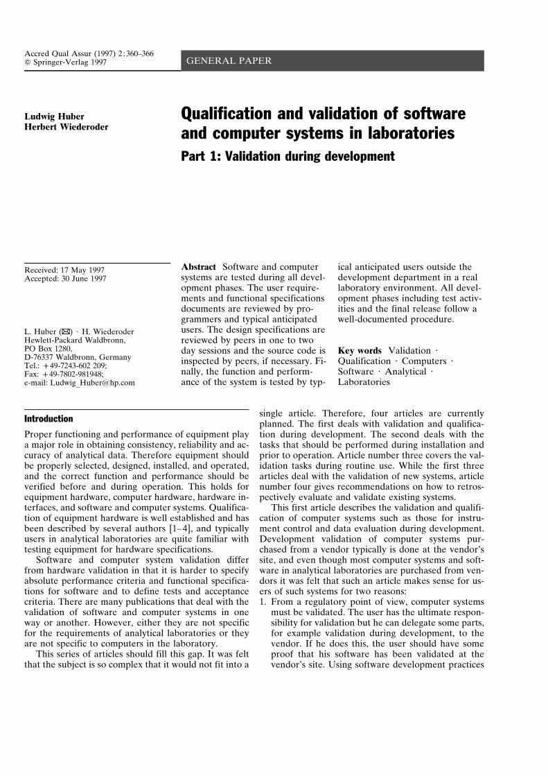
Fig. 1 The Hewlett-Packard CAG product life cycle model.ITQS: Information Technology Quality system
based on business and user needs. These describe howusers fulfill these needs now and how the new softwarecan provide better solutions. In the investigation phase,system reference specifications (user requirements) andexternal reference specifications (functional specifica-tions) are developed and reviewed. In the design phase,the design specifications are developed and reviewed.The implementation phase includes writing the codeand code inspections, if necessary. In the test phase,functional testing is performed with test cases for eachfunction as specified in the external reference specifica-tions document. After the product is shipped and used,feedback from users is recorded and documented, andchanges to the software are made following docu-mented change control procedure. Each phase is com-pleted, reviewed and approved before the subsequentphase is started.
Checkpoint meetings
Each phase ends with a checkpoint meeting. This isprepared by the project leader and attended by allmembers of the project team and managers from differ-ent departments. Team members report on their activi-ties during the phase and how they could meet the re-quirements as written in the development and valida-tion plan. The team and management go through thechecklist and discuss each point to determine whetherand how the checkpoint items have been fulfilled. Anaction plan with people assignment is put together aspart of the phase exit report for those items that are notyet closed. If all issues are resolved, the checklist issigned off by the management.
Proposal and investigation phases
The software life cycle starts with a requirements anal-ysis and product definition. These define the require-
ments that the product must meet for functionality,compatibility with existing systems, usability, perform-ance, reliability, supportability and security. The goal isto specify both the problem and the constraints uponthe solution. Planning activities include project plans,budgets, schedules and validation, verification and test-ing. During this phase the project team is established,usually comprising representatives from system devel-opment, product marketing, product support, qualityassurance, manufacturing and application chemists,who represent the users and are deeply involved in thedevelopment of a functional requirements specificationand in the user interface prototyping. A project teamleader is appointed to manage the project and a projectnotebook is created and maintained through the entiredevelopment phase.
Users from all application segments are interviewedby team members to discover their needs. Finally, a listwith all proposed functional requirements is drawn upand evaluated by the project team. Usually the list istoo long for all requirements to be implemented withina reasonable time-frame, so the requirements are prior-itized into three categories, “Musts”, “Wants” and“Nice to haves”. “Must” requirements are consideredto be those that are a prerequisite to the success of thesoftware and are always included in the final specifica-tions. “Wants” and “Nice to haves” are of lesser impor-tance and are included only if their implementationdoes not appreciably delay the project.
The external reference specifications (ERS) docu-ment is developed. This includes an overview of thescope and benefits of the project and a detailed descrip-tion of the complete product from a user’s perspective.The document is reviewed by the project team. It is thestarting point for system design and also the basis for– Design specifications document– Functional testing– The functional specifications document that is avail-
able for users to write their own requirement specifi-cations and operational qualifications or acceptancetesting
– The user documentation (e.g., user manual, on-linehelp).Feasibility studies are done if necessary. The soft-
ware engineering tools are determined and the soft-ware ‘make’ process is designed.
Deliverables for this phase include:– System reference specifications (user requirement
specifications)– External reference specifications (functional specifi-
cations)– Risk assessment– Quality plan
363
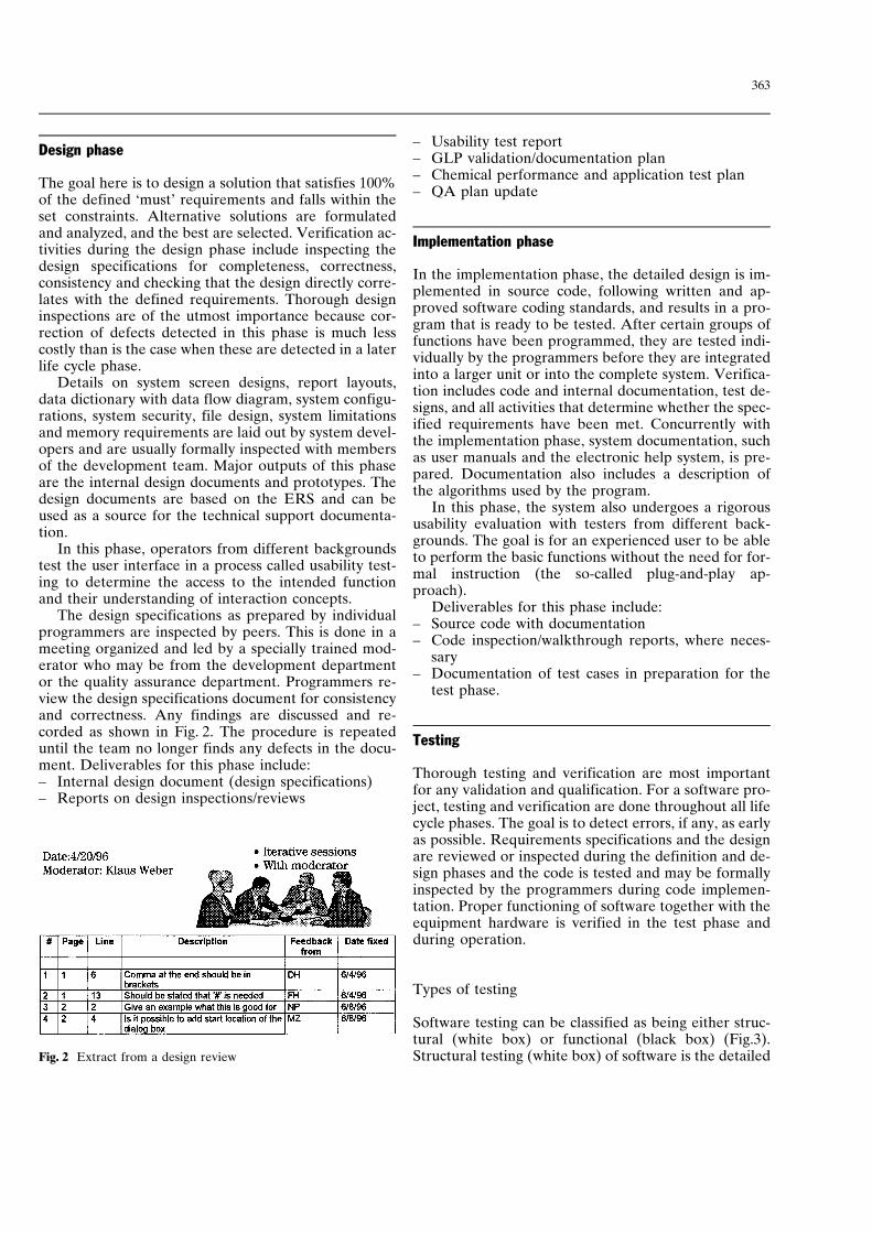
Fig. 2 Extract from a design review
Design phase
The goal here is to design a solution that satisfies 100%of the defined ‘must’ requirements and falls within theset constraints. Alternative solutions are formulatedand analyzed, and the best are selected. Verification ac-tivities during the design phase include inspecting thedesign specifications for completeness, correctness,consistency and checking that the design directly corre-lates with the defined requirements. Thorough designinspections are of the utmost importance because cor-rection of defects detected in this phase is much lesscostly than is the case when these are detected in a laterlife cycle phase.
Details on system screen designs, report layouts,data dictionary with data flow diagram, system configu-rations, system security, file design, system limitationsand memory requirements are laid out by system devel-opers and are usually formally inspected with membersof the development team. Major outputs of this phaseare the internal design documents and prototypes. Thedesign documents are based on the ERS and can beused as a source for the technical support documenta-tion.
In this phase, operators from different backgroundstest the user interface in a process called usability test-ing to determine the access to the intended functionand their understanding of interaction concepts.
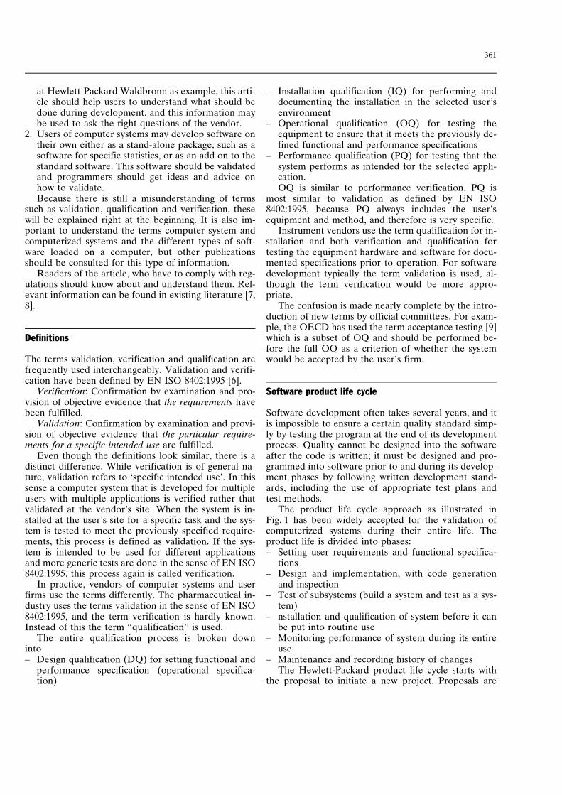
The design specifications as prepared by individualprogrammers are inspected by peers. This is done in ameeting organized and led by a specially trained mod-erator who may be from the development departmentor the quality assurance department. Programmers re-view the design specifications document for consistencyand correctness. Any findings are discussed and re-corded as shown in Fig. 2. The procedure is repeateduntil the team no longer finds any defects in the docu-ment. Deliverables for this phase include:– Internal design document (design specifications)– Reports on design inspections/reviews
– Usability test report– GLP validation/documentation plan– Chemical performance and application test plan– QA plan update
Implementation phase
In the implementation phase, the detailed design is im-plemented in source code, following written and ap-proved software coding standards, and results in a pro-gram that is ready to be tested. After certain groups offunctions have been programmed, they are tested indi-vidually by the programmers before they are integratedinto a larger unit or into the complete system. Verifica-tion includes code and internal documentation, test de-signs, and all activities that determine whether the spec-ified requirements have been met. Concurrently withthe implementation phase, system documentation, suchas user manuals and the electronic help system, is pre-pared. Documentation also includes a description ofthe algorithms used by the program.
In this phase, the system also undergoes a rigoroususability evaluation with testers from different back-grounds. The goal is for an experienced user to be ableto perform the basic functions without the need for for-mal instruction (the so-called plug-and-play ap-proach).
Deliverables for this phase include:– Source code with documentation– Code inspection/walkthrough reports, where neces-
sary– Documentation of test cases in preparation for the
test phase.
Testing
Thorough testing and verification are most importantfor any validation and qualification. For a software pro-ject, testing and verification are done throughout all lifecycle phases. The goal is to detect errors, if any, as earlyas possible. Requirements specifications and the designare reviewed or inspected during the definition and de-sign phases and the code is tested and may be formallyinspected by the programmers during code implemen-tation. Proper functioning of software together with theequipment hardware is verified in the test phase andduring operation.
Types of testing
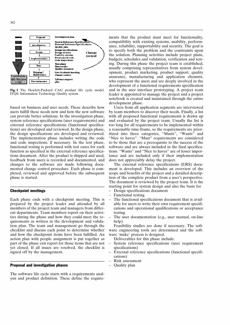
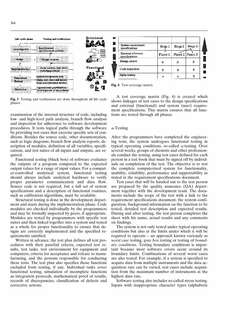
Software testing can be classified as being either struc-tural (white box) or functional (black box) (Fig.3).Structural testing (white box) of software is the detailed
364
Fig. 3 Testing and verification are done throughout all life cyclephases
Fig. 4 Test coverage matrix
examination of the internal structure of code, includinglow- and high-level path analysis, branch flow analysisand inspection for adherence to software developmentprocedures. It tests logical paths through the softwareby providing test cases that exercise specific sets of con-ditions. Besides the source code, other documentation,such as logic diagrams, branch flow analysis reports, de-scription of modules, definition of all variables, specifi-cations, and test suites of all inputs and outputs, are re-quired.
Functional testing (black box) of software evaluatesthe outputs of a program compared to the expectedoutput values for a range of input values. For a comput-er-controlled analytical system, functional testingshould always include analytical hardware to verifyproper parameter communication and data flow.Source code is not required, but a full set of systemspecifications and a description of functional routines,such as calibration algorithms, must be available.
Structural testing is done in the development depart-ment and starts during the implementation phase. Codemodules are checked individually by the programmersand may be formally inspected by peers, if appropriate.Modules are tested by programmers with specific testsuites and then linked together into a system and testedas a whole for proper functionality to ensure that de-signs are correctly implemented and the specified re-quirements satisfied.
Written in advance, the test plan defines all test pro-cedures with their pass/fail criteria, expected test re-sults, test tasks, test environment for equipment andcomputers, criteria for acceptance and release to manu-facturing, and the persons responsible for conductingthese tests. The test plan also specifies those functionsexcluded from testing, if any. Individual tasks coverfunctional testing, simulation of incomplete functionsas integration proceeds, mathematical proof of results,records of discrepancies, classification of defects andcorrective actions.
A test coverage matrix (Fig. 4) is created whichshows linkages of test cases to the design specificationsand external (functional) and system (user) require-ment specifications. This matrix ensures that all func-tions are tested through all phases.
a-Testing
After the programmers have completed the engineer-ing tests, the system undergoes functional testing intypical operating conditions, so-called a-testing. Overseveral weeks, groups of chemists and other profession-als conduct the testing, using test cases defined for eachperson in a test book that must be signed off by individ-uals on completion of the test. The objective is to testthe complete computerized system for functionality,usability, reliability, performance and supportability asstated in the requirement specifications document.
Test cases that will be handed out to the test personare prepared by the quality assurance (QA) depart-ment together with the development team. The docu-ments include the scope of the test with a link to therequirement specifications document, the system confi-guration, background information on the function to betested, detailed test description and expected results.During and after testing, the test person completes thesheet with his name, actual results and any commentson findings.
The system is not only tested under typical operatingconditions but also at the limits under which it will berequired to operate – an approach known variously asworst case testing, gray box testing or testing of bound-ary conditions. Testing boundary conditions is impor-tant because most software errors occur around itsboundary limits. Combinations of several worst casesare also tested. For example, if a system is specified toacquire data from multiple instruments and the data ac-quisition rate can be varied, test cases include acquisi-tion from the maximum number of instruments at thehighest data rate.
Software testing also includes so-called stress testing.Inputs with inappropriate character types (alphabetic
365
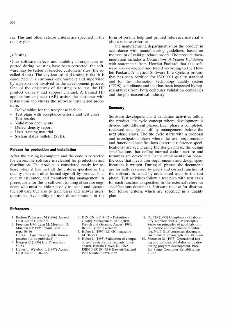
Table 1 Extract from an al-pha-test summary sheet Version Test time
(hours)Defects Cumulative
sum ofdefects
Defect disco-very rate(defects/hour)
Line fit
Vxxx
f
Vyyy
857396
788748
806979
331
80149232
472475476
0.940.860.82
0.040.030.02
1.051.041.03
0.230.230.23
The test results are evaluated using the Shooman Plot (10). The discovery rate is plotted versus thetotal number of defects discovered (Fig. 5). A regression linear fit curve is calculated and plottedtogether with maximum and minimum fits which by definition have a confidence interval of 5%.From the Shooman reliability model as shown in figure 5 the number of remaining defects can beestimated. This information is useful to forecast the number test cycles that are still necessary and apossible release date.The number of critical defects after the last test cycle must be zero for the software to pass therelease criteria. This and other release criteria are specified in the quality plan.
characters instead of numeric ones, for example, orinappropriate character length and character composi-tion) are made, and instrument parameters that lie out-side the instrument’s operational limits are entered.The expectation is that these inputs will not damagedata or disrupt system and software operation and thatthe system will recover after producing error mes-sages.
The test environment reflects as many system confi-gurations as possible. This includes different equipmentthat is controlled by the computer, different peripher-als, such as printers, CD ROMS, different internalmemory (RAM), and different operating systems, forexample, Windows 95 and NT.
Test cases reflect typical user applications with man-ual interactive and automated operation. Automatedsequences typically run over 24 h or more, where meth-ods are changed between runs. Data files with differentfile sizes are generated to make sure that system canhandle large files.
The user manual is prepared before the a-test to al-low test personnel to verify its accuracy and usefulness.At least one test case requires installation of the soft-ware and hardware according to the installation in-structions.
Defect tracking system
Documenting software errors is important and prob-lems should not be casually reported for repair by theprogrammer on an ad hoc basis. Problems found duringtesting are tracked using the HP internal defect controlsystem (DCS).
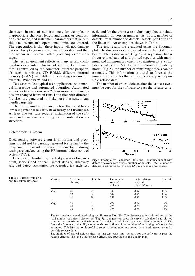
Defects are classified by the test person as low, me-dium, serious and critical. Defect density, discoveryrate and defect summaries are recorded for each test
Fig. 5 Example for Schooman Plots and Reliability model withdefect discovery rate versus number of defects. Total number ofdefects is estimated for average (AVG), best and worst case
cycle and for the entire a-test. Summary sheets includeinformation on version number, test hours, number ofdefects, total number of defects, defects per hour andthe linear fit. An example is shown in Table 1.
The test results are evaluated using the Shoomanplot. The discovery rate is plotted versus the total num-ber of defects discovered (Fig. 5). A regression linearfit curve is calculated and plotted together with maxi-mum and minimum fits which by definition have a con-fidence interval of 5%. From the Shooman reliabilitymodel (Fig. 5), the number of remaining defects can beestimated. This information is useful to forecast thenumber of test cycles that are still necessary and a pos-sible release date.
The number of critical defects after the last test cyclemust be zero for the software to pass the release crite-
366
ria. This and other release criteria are specified in thequality plan.
b-Testing
Once software defects and usability discrepancies re-ported during a-testing have been corrected, the soft-ware may be tested at selected customers’ sites (the so-called b-test). The key feature of b-testing is that it isconducted in a customer environment and supervisedby a person not involved in the development process.One of the objectives of b-testing is to test the HPproduct delivery and support channel. A trained HPapplications engineer (AE) assists the customer withinstallation and checks the software installation proce-dure.
Deliverables for the test phase include:– Test plans with acceptance criteria and test cases– Test results– Validation documents– Defect density report– User training material– System status bulletin (SSB).
Release for production and installation
After the testing is complete and the code is correctedfor errors, the software is released for production anddistribution. The product is considered ready for re-lease when it has met all the criteria specified in thequality plan and after formal sign-off by product line,quality assurance, and manufacturing management. Aprerequisite for this is sufficient training of service engi-neers who must be able not only to install and operatethe software but also to train users and answer users’questions. Availability of user documentation in the
form of on-line help and printed reference material isalso a release criterion.
The manufacturing department ships the product inaccordance with manufacturing guidelines, based onthe receipt of valid purchase orders. The product docu-mentation includes a Declaration of System Validationwith statements from Hewlett-Packard that the soft-ware was developed and tested according to the Hew-lett-Packard Analytical Software Life Cycle, a processthat has been certified for ISO 9001 quality standardand for the information technology quality system(ITQS) compliance and that has been inspected by rep-resentatives from both computer validation companiesand the pharmaceutical industry.
Summary
Software development and validation activities followthe product life cycle concept where development isdivided into different phases. Each phase is completed,reviewed and signed off by management before thenext phase starts. The life cycle starts with a proposaland investigation phase where the user requirementsand functional specifications (external reference speci-fications) are set. During the design phase, the designspecifications that define internal code structure andformulas are developed. In the implementation phase,the code that meets user requirements and design spec-ifications is written. During all phases, the documentsare formally reviewed by peers and correct function ofthe software is tested by anticipated users in the testphase. Test activities follow a test plan with test casesfor each function as specified in the external referencespecifications document. Software release for distribu-tion follow criteria which are specified in a qualityplan.
References
1. Bedson P, Sargent M (1996) AccredQual Assur 1 :265–274
2. Freeman HM, Leng M, Morrison D,Munden RP 1995 Pharm Tech Eu-rope 40–46
3. Huber L Equipment qualification inpractice (to be published)
4. Burgess C (1996) Eur Pharm Rev52–54
5. Huber L, Welebob L (1997) AccredQual Assur 2 :316–322
6. DIN EN ISO 8402 – Definitions:Quality Management, in English,French and German, August 1995,Beuth, Berlin, Germany
7. Huber L (1996) LC-GC magazine14 :502–508
8. Huber L (1995) Validation of compu-terized analytical instruments, Inter-pharm, Buffalo Grove, IL, USA,ISBN 0-935184-75-9 Hewlett-PackardPart Number :5959-3879
9. OECD (1992) Compliance of labora-tory suppliers with GLP principles,Series on principles of good laborato-ry practice and compliance monitor-ing, No. 5 GLP consensus document,environment monograph No. 49, Paris
10. Shooman M (1973) Operational test-ing and software reliability estimationduring program development, Proc.Int. Symp. Computer Reliability, pp51–57