Embed Size (px)
Citation preview

UPD 10.02.17
Page 1 of 19.
AEDON LLC. All rights reserved. �Тel:�+7�473�200-87-80 [email protected] eng.aedon.ru
QualificationTesting StandardsProduct platform MDV, MDR, MDN Families

UPD 10.02.17
Page 2 of 19.
AEDON LLC. All rights reserved. �Тel:�+7�473�200-87-80 [email protected] eng.aedon.ru
Environmental�Qualification�Testing�StandardsProduct platform MDV, MDR, MDN Families
Table�of�contents1. Testing ........................................................................................................................................................................................................................................................31.1.� Qualification�testing�..... . . . . . . . . . . . . . . . . . . . . . . . . . . . . . . . . . . . . . . . . . . . . . . . . . . . . . . . . . . . . . . . . . . . . . . . . . . . . . . . . . . . . . . . . . . . . . . . . . . . . . . . . . . . . . . . . . . . . . . . . . . . . . . . . . . . . . . . . . . . . . . . . . . . . . . . . . . . . . . . . . . . . . . . . . . . . . . . . . . . . . . . . . . . . . . . . . . . . . . . . . . . . . . . . . . . . .�4
1.2.� Periodical�testing�..... . . . . . . . . . . . . . . . . . . . . . . . . . . . . . . . . . . . . . . . . . . . . . . . . . . . . . . . . . . . . . . . . . . . . . . . . . . . . . . . . . . . . . . . . . . . . . . . . . . . . . . . . . . . . . . . . . . . . . . . . . . . . . . . . . . . . . . . . . . . . . . . . . . . . . . . . . . . . . . . . . . . . . . . . . . . . . . . . . . . . . . . . . . . . . . . . . . . . . . . . . . . . . . . . . . . . . . . . . .�4
1.3.� Acceptance�tests�..... . . . . . . . . . . . . . . . . . . . . . . . . . . . . . . . . . . . . . . . . . . . . . . . . . . . . . . . . . . . . . . . . . . . . . . . . . . . . . . . . . . . . . . . . . . . . . . . . . . . . . . . . . . . . . . . . . . . . . . . . . . . . . . . . . . . . . . . . . . . . . . . . . . . . . . . . . . . . . . . . . . . . . . . . . . . . . . . . . . . . . . . . . . . . . . . . . . . . . . . . . . . . . . . . . . . . . . . . . . . .4
2. Control of compliance to the requirements of the design ..........................................................................................................................................................................42.1.� External�..... . . . . . . . . . . . . . . . . . . . . . . . . . . . . . . . . . . . . . . . . . . . . . . . . . . . . . . . . . . . . . . . . . . . . . . . . . . . . . . . . . . . . . . . . . . . . . . . . . . . . . . . . . . . . . . . . . . . . . . . . . . . . . . . . . . . . . . . . . . . . . . . . . . . . . . . . . . . . . . . . . . . . . . . . . . . . . . . . . . . . . . . . . . . . . . . . . . . . . . . . . . . . . . . . . . . . . . . . . . . . . . . . . . . . . . . .4
2.2.� Durability�..... . . . . . . . . . . . . . . . . . . . . . . . . . . . . . . . . . . . . . . . . . . . . . . . . . . . . . . . . . . . . . . . . . . . . . . . . . . . . . . . . . . . . . . . . . . . . . . . . . . . . . . . . . . . . . . . . . . . . . . . . . . . . . . . . . . . . . . . . . . . . . . . . . . . . . . . . . . . . . . . . . . . . . . . . . . . . . . . . . . . . . . . . . . . . . . . . . . . . . . . . . . . . . . . . . . . . . . . . . . . . . . . . . . . . . .4
2.3.� Solderability�..... . . . . . . . . . . . . . . . . . . . . . . . . . . . . . . . . . . . . . . . . . . . . . . . . . . . . . . . . . . . . . . . . . . . . . . . . . . . . . . . . . . . . . . . . . . . . . . . . . . . . . . . . . . . . . . . . . . . . . . . . . . . . . . . . . . . . . . . . . . . . . . . . . . . . . . . . . . . . . . . . . . . . . . . . . . . . . . . . . . . . . . . . . . . . . . . . . . . . . . . . . . . . . . . . . . . . . . . . . . . . . . . . . .4
2.4.�� Heat�resistance�..... . . . . . . . . . . . . . . . . . . . . . . . . . . . . . . . . . . . . . . . . . . . . . . . . . . . . . . . . . . . . . . . . . . . . . . . . . . . . . . . . . . . . . . . . . . . . . . . . . . . . . . . . . . . . . . . . . . . . . . . . . . . . . . . . . . . . . . . . . . . . . . . . . . . . . . . . . . . . . . . . . . . . . . . . . . . . . . . . . . . . . . . . . . . . . . . . . . . . . . . . . . . . . . . . . . . . . . . . . . . . . .5
2.5.� Weight . . . . . . . . . . . . . . . . . . . . . . . . . . . . . . . . . . . . . . . . . . . . . . . . . . . . . . . . . . . . . . . . . . . . . . . . . . . . . . . . . . . . . . . . . . . . . . . . . . . . . . . . . . . . . . . . . . . . . . . . . . . . . . . . . . . . . . . . . . . . . . . . . . . . . . . . . . . . . . . . . . . . . . . . . . . . . . . . . . . . . . . . . . . . . . . . . . . . . . . . . . . . . . . . . . . . . . . . . . . . . . . . . . . . . . . . . . . . . . .5
3. Control of compliance to electric parameters and electric operating modes ...........................................................................................................................................63.1.� Isolation�voltage�..... . . . . . . . . . . . . . . . . . . . . . . . . . . . . . . . . . . . . . . . . . . . . . . . . . . . . . . . . . . . . . . . . . . . . . . . . . . . . . . . . . . . . . . . . . . . . . . . . . . . . . . . . . . . . . . . . . . . . . . . . . . . . . . . . . . . . . . . . . . . . . . . . . . . . . . . . . . . . . . . . . . . . . . . . . . . . . . . . . . . . . . . . . . . . . . . . . . . . . . . . . . . . . . . . . . . . . . . . . . .�7
3.2.� Isolation�resistance�..... . . . . . . . . . . . . . . . . . . . . . . . . . . . . . . . . . . . . . . . . . . . . . . . . . . . . . . . . . . . . . . . . . . . . . . . . . . . . . . . . . . . . . . . . . . . . . . . . . . . . . . . . . . . . . . . . . . . . . . . . . . . . . . . . . . . . . . . . . . . . . . . . . . . . . . . . . . . . . . . . . . . . . . . . . . . . . . . . . . . . . . . . . . . . . . . . . . . . . . . . . . . . . . . . . . . . . . .�7
3.3.� Output�voltage�setup�...... . . . . . . . . . . . . . . . . . . . . . . . . . . . . . . . . . . . . . . . . . . . . . . . . . . . . . . . . . . . . . . . . . . . . . . . . . . . . . . . . . . . . . . . . . . . . . . . . . . . . . . . . . . . . . . . . . . . . . . . . . . . . . . . . . . . . . . . . . . . . . . . . . . . . . . . . . . . . . . . . . . . . . . . . . . . . . . . . . . . . . . . . . . . . . . . . . . . . . . . . . . . . . . . . . . .�7
3.4.� Output�voltage�ripple�..... . . . . . . . . . . . . . . . . . . . . . . . . . . . . . . . . . . . . . . . . . . . . . . . . . . . . . . . . . . . . . . . . . . . . . . . . . . . . . . . . . . . . . . . . . . . . . . . . . . . . . . . . . . . . . . . . . . . . . . . . . . . . . . . . . . . . . . . . . . . . . . . . . . . . . . . . . . . . . . . . . . . . . . . . . . . . . . . . . . . . . . . . . . . . . . . . . . . . . . . . . . . . . . . . . . . .�8
3.5.� Set�output�voltage�deviation�..... . . . . . . . . . . . . . . . . . . . . . . . . . . . . . . . . . . . . . . . . . . . . . . . . . . . . . . . . . . . . . . . . . . . . . . . . . . . . . . . . . . . . . . . . . . . . . . . . . . . . . . . . . . . . . . . . . . . . . . . . . . . . . . . . . . . . . . . . . . . . . . . . . . . . . . . . . . . . . . . . . . . . . . . . . . . . . . . . . . . . . . . . . . . . . . . . . . . . . . . . .�8
3.6.� Transient�deviation�of�output�voltage�..... . . . . . . . . . . . . . . . . . . . . . . . . . . . . . . . . . . . . . . . . . . . . . . . . . . . . . . . . . . . . . . . . . . . . . . . . . . . . . . . . . . . . . . . . . . . . . . . . . . . . . . . . . . . . . . . . . . . . . . . . . . . . . . . . . . . . . . . . . . . . . . . . . . . . . . . . . . . . . . . . . . . . . . . . . . . . . . . . . . . . . . . . . . . . .8
3.7.�� Total�output�regulation�..... . . . . . . . . . . . . . . . . . . . . . . . . . . . . . . . . . . . . . . . . . . . . . . . . . . . . . . . . . . . . . . . . . . . . . . . . . . . . . . . . . . . . . . . . . . . . . . . . . . . . . . . . . . . . . . . . . . . . . . . . . . . . . . . . . . . . . . . . . . . . . . . . . . . . . . . . . . . . . . . . . . . . . . . . . . . . . . . . . . . . . . . . . . . . . . . . . . . . . . . . . . . . . . . . .�9
3.8.� Overload�protection�..... . . . . . . . . . . . . . . . . . . . . . . . . . . . . . . . . . . . . . . . . . . . . . . . . . . . . . . . . . . . . . . . . . . . . . . . . . . . . . . . . . . . . . . . . . . . . . . . . . . . . . . . . . . . . . . . . . . . . . . . . . . . . . . . . . . . . . . . . . . . . . . . . . . . . . . . . . . . . . . . . . . . . . . . . . . . . . . . . . . . . . . . . . . . . . . . . . . . . . . . . . . . . . . . . . . . . . .�9
3.9.� Output�overvoltage�protection�..... . . . . . . . . . . . . . . . . . . . . . . . . . . . . . . . . . . . . . . . . . . . . . . . . . . . . . . . . . . . . . . . . . . . . . . . . . . . . . . . . . . . . . . . . . . . . . . . . . . . . . . . . . . . . . . . . . . . . . . . . . . . . . . . . . . . . . . . . . . . . . . . . . . . . . . . . . . . . . . . . . . . . . . . . . . . . . . . . . . . . . . . . . . . . . . . . . . . . .10
3.10.� No�load�operation�..... . . . . . . . . . . . . . . . . . . . . . . . . . . . . . . . . . . . . . . . . . . . . . . . . . . . . . . . . . . . . . . . . . . . . . . . . . . . . . . . . . . . . . . . . . . . . . . . . . . . . . . . . . . . . . . . . . . . . . . . . . . . . . . . . . . . . . . . . . . . . . . . . . . . . . . . . . . . . . . . . . . . . . . . . . . . . . . . . . . . . . . . . . . . . . . . . . . . . . . . . . . . . . . . . . . . . . . .�10
3.11.� Current�..... . . . . . . . . . . . . . . . . . . . . . . . . . . . . . . . . . . . . . . . . . . . . . . . . . . . . . . . . . . . . . . . . . . . . . . . . . . . . . . . . . . . . . . . . . . . . . . . . . . . . . . . . . . . . . . . . . . . . . . . . . . . . . . . . . . . . . . . . . . . . . . . . . . . . . . . . . . . . . . . . . . . . . . . . . . . . . . . . . . . . . . . . . . . . . . . . . . . . . . . . . . . . . . . . . . . . . . . . . . . . . . . . . . . . . . .�10
3.12.� Power�..... . . . . . . . . . . . . . . . . . . . . . . . . . . . . . . . . . . . . . . . . . . . . . . . . . . . . . . . . . . . . . . . . . . . . . . . . . . . . . . . . . . . . . . . . . . . . . . . . . . . . . . . . . . . . . . . . . . . . . . . . . . . . . . . . . . . . . . . . . . . . . . . . . . . . . . . . . . . . . . . . . . . . . . . . . . . . . . . . . . . . . . . . . . . . . . . . . . . . . . . . . . . . . . . . . . . . . . . . . . . . . . . . . . . . . . . . .�10
3.13.� Efficiency�..... . . . . . . . . . . . . . . . . . . . . . . . . . . . . . . . . . . . . . . . . . . . . . . . . . . . . . . . . . . . . . . . . . . . . . . . . . . . . . . . . . . . . . . . . . . . . . . . . . . . . . . . . . . . . . . . . . . . . . . . . . . . . . . . . . . . . . . . . . . . . . . . . . . . . . . . . . . . . . . . . . . . . . . . . . . . . . . . . . . . . . . . . . . . . . . . . . . . . . . . . . . . . . . . . . . . . . . . . . . . . . . . . . . . .�10
3.14.� Remote�power�off�..... . . . . . . . . . . . . . . . . . . . . . . . . . . . . . . . . . . . . . . . . . . . . . . . . . . . . . . . . . . . . . . . . . . . . . . . . . . . . . . . . . . . . . . . . . . . . . . . . . . . . . . . . . . . . . . . . . . . . . . . . . . . . . . . . . . . . . . . . . . . . . . . . . . . . . . . . . . . . . . . . . . . . . . . . . . . . . . . . . . . . . . . . . . . . . . . . . . . . . . . . . . . . . . . . . . . . . . .�10
3.15.� Parallel�operation�..... . . . . . . . . . . . . . . . . . . . . . . . . . . . . . . . . . . . . . . . . . . . . . . . . . . . . . . . . . . . . . . . . . . . . . . . . . . . . . . . . . . . . . . . . . . . . . . . . . . . . . . . . . . . . . . . . . . . . . . . . . . . . . . . . . . . . . . . . . . . . . . . . . . . . . . . . . . . . . . . . . . . . . . . . . . . . . . . . . . . . . . . . . . . . . . . . . . . . . . . . . . . . . . . . . . . . . . .�10
3.16.� Output�voltage�setup�...... . . . . . . . . . . . . . . . . . . . . . . . . . . . . . . . . . . . . . . . . . . . . . . . . . . . . . . . . . . . . . . . . . . . . . . . . . . . . . . . . . . . . . . . . . . . . . . . . . . . . . . . . . . . . . . . . . . . . . . . . . . . . . . . . . . . . . . . . . . . . . . . . . . . . . . . . . . . . . . . . . . . . . . . . . . . . . . . . . . . . . . . . . . . . . . . . . . . . . . . . . . . . . . . . .�11
4. Control of compliance to the requirements of environmental stability ..................................................................................................................................................114.1.� Vibration�resistance�and�strength�..... . . . . . . . . . . . . . . . . . . . . . . . . . . . . . . . . . . . . . . . . . . . . . . . . . . . . . . . . . . . . . . . . . . . . . . . . . . . . . . . . . . . . . . . . . . . . . . . . . . . . . . . . . . . . . . . . . . . . . . . . . . . . . . . . . . . . . . . . . . . . . . . . . . . . . . . . . . . . . . . . . . . . . . . . . . . . . . . . . . . . . . . . . . . . . . . .11
4.2.� Shock�resistance�and�strength�..... . . . . . . . . . . . . . . . . . . . . . . . . . . . . . . . . . . . . . . . . . . . . . . . . . . . . . . . . . . . . . . . . . . . . . . . . . . . . . . . . . . . . . . . . . . . . . . . . . . . . . . . . . . . . . . . . . . . . . . . . . . . . . . . . . . . . . . . . . . . . . . . . . . . . . . . . . . . . . . . . . . . . . . . . . . . . . . . . . . . . . . . . . . . . . . . . . . . . .11
4.3.� Single�impacts�..... . . . . . . . . . . . . . . . . . . . . . . . . . . . . . . . . . . . . . . . . . . . . . . . . . . . . . . . . . . . . . . . . . . . . . . . . . . . . . . . . . . . . . . . . . . . . . . . . . . . . . . . . . . . . . . . . . . . . . . . . . . . . . . . . . . . . . . . . . . . . . . . . . . . . . . . . . . . . . . . . . . . . . . . . . . . . . . . . . . . . . . . . . . . . . . . . . . . . . . . . . . . . . . . . . . . . . . . . . . . .�12
4.4.� High�ambient�temperature�..... . . . . . . . . . . . . . . . . . . . . . . . . . . . . . . . . . . . . . . . . . . . . . . . . . . . . . . . . . . . . . . . . . . . . . . . . . . . . . . . . . . . . . . . . . . . . . . . . . . . . . . . . . . . . . . . . . . . . . . . . . . . . . . . . . . . . . . . . . . . . . . . . . . . . . . . . . . . . . . . . . . . . . . . . . . . . . . . . . . . . . . . . . . . . . . . . . . . . . . . . . .�12
4.5.� Low�ambient�temperature�..... . . . . . . . . . . . . . . . . . . . . . . . . . . . . . . . . . . . . . . . . . . . . . . . . . . . . . . . . . . . . . . . . . . . . . . . . . . . . . . . . . . . . . . . . . . . . . . . . . . . . . . . . . . . . . . . . . . . . . . . . . . . . . . . . . . . . . . . . . . . . . . . . . . . . . . . . . . . . . . . . . . . . . . . . . . . . . . . . . . . . . . . . . . . . . . . . . . . . . . . . . . .�13
4.6.� Rapid�ambient�temperature�change�...... . . . . . . . . . . . . . . . . . . . . . . . . . . . . . . . . . . . . . . . . . . . . . . . . . . . . . . . . . . . . . . . . . . . . . . . . . . . . . . . . . . . . . . . . . . . . . . . . . . . . . . . . . . . . . . . . . . . . . . . . . . . . . . . . . . . . . . . . . . . . . . . . . . . . . . . . . . . . . . . . . . . . . . . . . . . . . . . . . . . . . . . . . . . .13
4.7.�� High�humidity�..... . . . . . . . . . . . . . . . . . . . . . . . . . . . . . . . . . . . . . . . . . . . . . . . . . . . . . . . . . . . . . . . . . . . . . . . . . . . . . . . . . . . . . . . . . . . . . . . . . . . . . . . . . . . . . . . . . . . . . . . . . . . . . . . . . . . . . . . . . . . . . . . . . . . . . . . . . . . . . . . . . . . . . . . . . . . . . . . . . . . . . . . . . . . . . . . . . . . . . . . . . . . . . . . . . . . . . . . . . . . . .�13
4.8.� Low�atmospheric�pressure�..... . . . . . . . . . . . . . . . . . . . . . . . . . . . . . . . . . . . . . . . . . . . . . . . . . . . . . . . . . . . . . . . . . . . . . . . . . . . . . . . . . . . . . . . . . . . . . . . . . . . . . . . . . . . . . . . . . . . . . . . . . . . . . . . . . . . . . . . . . . . . . . . . . . . . . . . . . . . . . . . . . . . . . . . . . . . . . . . . . . . . . . . . . . . . . . . . . . . . . . . . . . .14
4.9.� High�atmospheric�pressure�..... . . . . . . . . . . . . . . . . . . . . . . . . . . . . . . . . . . . . . . . . . . . . . . . . . . . . . . . . . . . . . . . . . . . . . . . . . . . . . . . . . . . . . . . . . . . . . . . . . . . . . . . . . . . . . . . . . . . . . . . . . . . . . . . . . . . . . . . . . . . . . . . . . . . . . . . . . . . . . . . . . . . . . . . . . . . . . . . . . . . . . . . . . . . . . . . . . . . . . . . . . .14
4.10.� Radio�interference�voltage�..... . . . . . . . . . . . . . . . . . . . . . . . . . . . . . . . . . . . . . . . . . . . . . . . . . . . . . . . . . . . . . . . . . . . . . . . . . . . . . . . . . . . . . . . . . . . . . . . . . . . . . . . . . . . . . . . . . . . . . . . . . . . . . . . . . . . . . . . . . . . . . . . . . . . . . . . . . . . . . . . . . . . . . . . . . . . . . . . . . . . . . . . . . . . . . . . . . . . . . . . . . . .14
4.11.� Precipitation�..... . . . . . . . . . . . . . . . . . . . . . . . . . . . . . . . . . . . . . . . . . . . . . . . . . . . . . . . . . . . . . . . . . . . . . . . . . . . . . . . . . . . . . . . . . . . . . . . . . . . . . . . . . . . . . . . . . . . . . . . . . . . . . . . . . . . . . . . . . . . . . . . . . . . . . . . . . . . . . . . . . . . . . . . . . . . . . . . . . . . . . . . . . . . . . . . . . . . . . . . . . . . . . . . . . . . . . . . . . . . . . . .�14
4.12.� Salt�fog�(marine)�..... . . . . . . . . . . . . . . . . . . . . . . . . . . . . . . . . . . . . . . . . . . . . . . . . . . . . . . . . . . . . . . . . . . . . . . . . . . . . . . . . . . . . . . . . . . . . . . . . . . . . . . . . . . . . . . . . . . . . . . . . . . . . . . . . . . . . . . . . . . . . . . . . . . . . . . . . . . . . . . . . . . . . . . . . . . . . . . . . . . . . . . . . . . . . . . . . . . . . . . . . . . . . . . . . . . . . . . . . . .15
4.13.� Static�dust�(sand)�..... . . . . . . . . . . . . . . . . . . . . . . . . . . . . . . . . . . . . . . . . . . . . . . . . . . . . . . . . . . . . . . . . . . . . . . . . . . . . . . . . . . . . . . . . . . . . . . . . . . . . . . . . . . . . . . . . . . . . . . . . . . . . . . . . . . . . . . . . . . . . . . . . . . . . . . . . . . . . . . . . . . . . . . . . . . . . . . . . . . . . . . . . . . . . . . . . . . . . . . . . . . . . . . . . . . . . . . . . .15
5. Reliability compliance control .................................................................................................................................................................................................................16
6. Testing and control of DC/DC converters in production .............................................................................................................................................................................176.1.� Control�of�surface�mounting�by�automatic�optical�inspection�..... . . . . . . . . . . . . . . . . . . . . . . . . . . . . . . . . . . . . . . . . . . . . . . . . . . . . . . . . . . . . . . . . . . . . . . . . . . . . . . . . . . . . . . . . . . . . . . . . . . . . . . . . . . . . . . . . . . . . . . . . . . . . . . . . . . . . . . . . . . . . . . . . . . . . . . . .17
6.2.� QCD�inspection�of�soldered�joints�quality�of�air�and�surface�mounting�by�automatic�optical�inspection�..... . . . . . . . . . . . . . . . . . . . . . . . . . . . . . . . . . . . . . . . . . . . . . . . . . . . . . . . . . . . . . . . . . . . . . . . . . . . . . . . . . . . . . . . . .17
6.3.� Control�of�electric�parameters�during�production�..... . . . . . . . . . . . . . . . . . . . . . . . . . . . . . . . . . . . . . . . . . . . . . . . . . . . . . . . . . . . . . . . . . . . . . . . . . . . . . . . . . . . . . . . . . . . . . . . . . . . . . . . . . . . . . . . . . . . . . . . . . . . . . . . . . . . . . . . . . . . . . . . . . . . . . . . . . . . . . . . . . . . . . . . . .17
6.4.� QCD�inspection�of�product�assembly�accuracy�..... . . . . . . . . . . . . . . . . . . . . . . . . . . . . . . . . . . . . . . . . . . . . . . . . . . . . . . . . . . . . . . . . . . . . . . . . . . . . . . . . . . . . . . . . . . . . . . . . . . . . . . . . . . . . . . . . . . . . . . . . . . . . . . . . . . . . . . . . . . . . . . . . . . . . . . . . . . . . . . . . . . . . . . . . . . . . . .17
6.5.� Isolation�resistance�check�..... . . . . . . . . . . . . . . . . . . . . . . . . . . . . . . . . . . . . . . . . . . . . . . . . . . . . . . . . . . . . . . . . . . . . . . . . . . . . . . . . . . . . . . . . . . . . . . . . . . . . . . . . . . . . . . . . . . . . . . . . . . . . . . . . . . . . . . . . . . . . . . . . . . . . . . . . . . . . . . . . . . . . . . . . . . . . . . . . . . . . . . . . . . . . . . . . . . . . . . . . . . . .17
6.6.� Operation�test�of�products�at�the�lowest�temperature�of�the�operating�temperature�range�...... . . . . . . . . . . . . . . . . . . . . . . . . . . . . . . . . . . . . . . . . . . . . . . . . . . . . . . . . . . . . . . . . . . . . . . . . . . . . . . . . . . . . . . . . . . . . . . . . . . . . . . . . . .18
6.7.� Long-term�testing�of�powered-on�units�at�the�highest�operating�temperature�measured�on�the�product’s�case�..... . . . . . . . . . . . . . . . . . . . . . . . . . . . . . . . . . . . . . . . . . . . . . . . . . . . . . . . . . . . . . . . . . . . . . . . . . . . . . .18
6.8.�� Isolation�resistance�test�..... . . . . . . . . . . . . . . . . . . . . . . . . . . . . . . . . . . . . . . . . . . . . . . . . . . . . . . . . . . . . . . . . . . . . . . . . . . . . . . . . . . . . . . . . . . . . . . . . . . . . . . . . . . . . . . . . . . . . . . . . . . . . . . . . . . . . . . . . . . . . . . . . . . . . . . . . . . . . . . . . . . . . . . . . . . . . . . . . . . . . . . . . . . . . . . . . . . . . . . . . . . . . . . .18
6.9.� Electric�parameters�verification�by�factory�QCD�...... . . . . . . . . . . . . . . . . . . . . . . . . . . . . . . . . . . . . . . . . . . . . . . . . . . . . . . . . . . . . . . . . . . . . . . . . . . . . . . . . . . . . . . . . . . . . . . . . . . . . . . . . . . . . . . . . . . . . . . . . . . . . . . . . . . . . . . . . . . . . . . . . . . . . . . . . . . . . . . . . . . . . . . . . . . .18
6.10.� External�inspection�of�the�product,�accompanying�documents�set�and�accuracy�of�packing�..... . . . . . . . . . . . . . . . . . . . . . . . . . . . . . . . . . . . . . . . . . . . . . . . . . . . . . . . . . . . . . . . . . . . . . . . . . . . . . . . . . . . . . . . . . . . . . . . . . . . . . . . . . . .18

UPD 10.02.17
Page�3�of�19.
AEDON LLC. All rights reserved. �Тel:�+7�473�200-87-80 [email protected] eng.aedon.ru
Environmental�Qualification�Testing�StandardsProduct platform MDV, MDR, MDN Families
Qualificatio
n
Perio
dica
l
Acce
ptan
ce
Check�of�appearance,�legibility�and�content�of�labeling + + +
Durability�test�of�marking + + +
Control�of�overall�dimensions,�setting�and�mounting�dimensions + + +
Control�of�electrical�insulation�resistance + + +
Control�of�stable�output�voltage�deviation + + +
Control�total�regulation:������—�output�voltage�regulation�with�smooth�alteration�of�input�voltage�and�output�current�(HU+HI);������—�thermal�instability�of�output�voltage;�������—�temporal�instability�of�output�voltage
+ + +
Control�of�output�voltage�ripple + + +
Control�of�overvoltage,�overcurrent�and�short-circuit�protection. + + +
Control�of�manual�adjustment�limits. + + +
Remote�power-on�control.� + + +
Check�of�voltage�of�no�load�operation + + +
Functional�testing�of�parallel�operation + + +
Short-term�operational�reliability�testing + +
Vibration�strength�test�(short-term) + +
Vibration�resistance�test + +
Shock�strength�test + +
Shock�resistance�test + +
Single�impact�test +
Ambient�temperature�change�impact�test�(Temperature�Cycling�Test) + +
High�ambient�temperature�operation�test + +
Low�ambient�temperature�operation�test + +
High�humidity�test�(accelerated) + +
Weight�control + +
Marking�resistance�to�cleaning�solvents + +
Solderability�test�of�pins�and�terminal�blocks + +
Heat�resistance�during�soldering + +
Durability�test�of�output�pins�and�connection�of�external�pins�with�conducting�elements + +
Isolation�voltage�control + +
Control�of�output�voltage�transient�deviation + +
Control�of�output�voltage�setup�time + +
Total�regulation�control + +
Control�of�current�consumed�from�the�mains�at�power-on. + +
Control�of�full�consumed�power. + +
Efficiency�control + +
Control�of�output�overvoltage�protection + +
Failure-free�operation�test�(long-term) +
Control�of�packing�overall�dimensions� +
Packing�durability�control� +
Salt�(sea)�fog�testing +
Atmospheric�сondensed�precipitation�(frost,�dew)�test. +
Static�dust�(sand)�testing +
High�humidity�test�(long-term) +
Marking�test�for�legibility�and�durability�during�transportation,�operation�and�storage +
Test�for�critical�frequency�absence�check +
Control�of�industrial�radiointerference�level +
Testing�of�basic�design�and�technological�safety�margins +
All�specifications�valid�for�normal�climatic�conditions�(ambient�temp.�15...35°C;�relative�humidity�45…80%;�air�pressure�
8,6*104…10,6*104�Pa),�Uin.�nom,�Iout.�nom,�unless�otherwise�stated.
1. List of tests

UPD 10.02.17
Page�4�of�19.
AEDON LLC. All rights reserved. �Тel:�+7�473�200-87-80 [email protected] eng.aedon.ru
Environmental�Qualification�Testing�StandardsProduct platform MDV, MDR, MDN Families
1.1. Qualification testing
Testing�of�products�for�compliance�to�the�Specifications�carried�at�implementation�into�production�to�estimate�the�
readiness�of�the�factory�and�products�for�manufacturing.
1.2. Periodical testing
Control�testing�of�product�samples�for�compliance�to�the�Specifications�with�the�purpose�of�periodical�performance�
consistency�check,�compliance� to�Specifications�and�possibility�of� further�production.�Units�passed�acceptance�
tests are used for testing.
Frequency�of�periodical�testing�—�once�per�year.
1.3. Acceptance tests
Control�tests�of�manufactured�products�for�compliance�to�the�Specifications,�results�of�which��are�used�to�make�
decision�of�usability�for�delivery�and/or�application.��After�storing�modules�on�stock�over�6�months�they�must�be�
verified�prior�to�shipment�to�the�consumer�in�the�amount�necessary�for�acceptance�tests.
2.�Control�of�compliance�to�the�requirements�of�design��
2.1. External
External�inspection�is�used�to�check�quality�and�integrity�of�coatings,�structural�integrity,�fastening�places,�as�well�
as�the�absence�of�dents,�cracks,�and�traces�of�corrosion�on�the�outer�surfaces.
Applied�standard GOST�20.57.406�method�405-1
2.2. Durability
Durability�of�output�pins�is�checked�by�applying�stretching�force��directed�along�axis�of�the�pin�with�the�help�of�
weight�and�a�clamping��device.�
Stretching�force�is�applied�at�the�distance�of�max�4�mm�from�the�end�of�each�pin�for�(10±1)�sec.�
Diameter of pins, mm Force, N0,8 10
1,0 20
1,5 40
Control of testing allowable�deviation�of�values�—�max�±10%
Applied�standard GOST�20.57.406�method�109-1
2.3. Solderability
Solderability�of�output�pins�is�controlled�using�soldering�iron�and�braze�POS�61.
First� product� undergoes� artificial� aging:� the�product� is� exposed� to� constant� extreme�humidity� for� 10�days� at�
temperature�of�(40±2)°C�and�relative�humidity�(93±3)%.�The�temperature�of�the�soldering�tip�must�be�(350±10)°C.�
Exposure�time�—�5�ses.�Number�of�pins�under�test�—�three.
It�is�allowed�to�have�defects�(pores,�cavities)�not�concentrated�in�one�place.�Stretching�force�is�applied�at�distance�
of�4�mm�max�from�the�end�of�each�output�pin�for�(10±1)�sec.
Control of testing Magnifier�x4–10
Applied�standard GOST�20.57.406�method�402-2
External product inspection.

UPD 10.02.17
Page�5�of�19.
AEDON LLC. All rights reserved. �Тel:�+7�473�200-87-80 [email protected] eng.aedon.ru
Environmental�Qualification�Testing�StandardsProduct platform MDV, MDR, MDN Families
2.4. Heat resistance
Heat�resistance�during�soldering�is�controlled�using�soldering�iron�and�braze�POS�61.
The�temperature�of�the�soldering�tip�must�be�(350±10)°C.�Exposure�time�—�5�sec.�Number�of�pins�under�test�—�
three.�Re-soldering�test�is�allowed�not�to�hold�if�during�other�tests�the�pins�are�re-soldered�at�least�three�times�
for�measuring�electric�parameters.
Control of testing Magnifier�x4–10
Applied�standard GOST�20.57.406�method�403-2
2.5 Weight
Weight�is�controlled�by�weighing�on�scales.
Control of testing allowable�error�max�±5%
Applied�standard GOST�20.57.406�method�406-1
UPD 10.02.17
Page�6�of�19.
AEDON LLC. All rights reserved. �Тel:�+7�473�200-87-80 [email protected] eng.aedon.ru
Environmental�Qualification�Testing�StandardsProduct platform MDV, MDR, MDN Families
3.�Control�of�compliance�to�electric�parameters�and�electric�operating�modes
Control�of�electric�parameters�before�and�after�testing�at�normal�climatic�conditions.
Layout 1.�Parameters�measurement�of�single-channel�power�supply�units.
С2,�С6 Ceramic�or�polymer�film�capacitor�(depends�on�the�nominal�value�of�the�mains�and�power�of�the�converter)�is�described�in�the�Specifications.
С1 Tantalum�or�electrolytic�capacitor�(depends�on�the�nominal�value�of�the�mains�and�power�of�the�converter)�is�described�in�the�Specifications.
С3,�С5 Ceramic�capacitor�3300�pF,�3�kW
С4 Tantalum�capacitor�(depends�on�the�value�of�the�output�voltage�and�power�of�the�converters)�is�described�in�the�Specifications.
L1 Choke�0.5�mH�for�low-voltage�networks,�5�mH�for�high�voltage
R4 Resistor�0.25–47�Ohm
R5 Resistor�0.25–470�Ohms
S1,�S3,�S5...S7 Toggle�switch�or�circuit�breaker
S2 Button
S4 Switch
S8 Switch
VD1,�VD2 Diode
Electronic equipment adjuster’s workplace. Control room of electric parameters.

UPD 10.02.17
Page 7 of 19.
AEDON LLC. All rights reserved. �Тel:�+7�473�200-87-80 [email protected] eng.aedon.ru
Environmental�Qualification�Testing�StandardsProduct platform MDV, MDR, MDN Families
3.1. Isolation voltage
Isolation�voltage�of�the�units�is�checked�by�universal�breakdown�tester�UPU-10M�or�its�equivalent�within�1�minute�
under�50�Hz�test�voltage.
Input-case,�input-output�nominal�input�voltage�A,�B,�V,�D,�E,�W 500�VDC
Input-case,�input-output�nominal�input�voltage�N,�M 1500�VDC
Output-Case,�Output-Output� 500
For power supply units the tester is connected between points “1” and “2”, “1” and “3”, “2” and “3” (Figure 1), where:
— point “1” - connected pins “+IN”, “-IN” and “ON”;
— point “2” - “CASE” pin connected with the base or flange of the case;
— point “3” - pins of all channels connected between each other, “ADJ”, “PARAL”, “-RS”, “+RS”.
Control of testing allowable�error�max�±5%
Applied�standard GOST�12997
3.2. Isolation resistance
Isolation�electric�resistance�of�units�is�checked�by�test�500VDC�voltage.
For power supply units the tester is connected between points “1” and “2”, “1” and “3”, “1” and “4”, “1” and “5”, “2”
and “3”, “2” and “4”, “2” and “5”, “3” and “4”, “3” and “5”, “4” and “5”, where:
— point “1” - connected pins “+IN”, “-IN” and “ON”;
— point “2” - “CASE” pin connected with the base or flange of the case;
— point “3” - pins “+OUT” and “-OUT” of the first channel, “ADJ”, “PARAL”, “-RS”, “+RS” connected between each other;
— point “4” - pins “+OUT2” and “-OUT2” of the second channel connected between each other;
— point “5” - pins “+OUT3” and “-OUT3” of the third channel connected between each other;
The�readings�are�registered�every�1�minute�after�supplying�the�measuring�voltage�or�less�time�if��the�isolation�
voltage�does�not�change.�
Consider the following test modules, if the insulation resistance iswithin�normal�climatic�conditions at least 20 MOhm
at�high�(low)�operating�temperature at�least�5�MOhm
at�high�humidity at least 1 MOhm
Control of testing allowable�error�max�±5%
Applied�standard GOST�12997
3.3. Output voltage setup
Output�voltage�set-up�time�of�power�supply�units�is�checked�within�normal�climatic�conditions�at�nominal�input�
voltage�and�max�output�current�of�single-channel�units�and�all�channels�of�multi-channel�units.�Output�voltage�
set-up�time�is�defined�as�a�period�of�time�between�supply�of�control�signal�to�“ON”�pin�and�time�when�output�
voltage�reaches�the�nominal�value�with�account�for�the�total�regulation.
The�units�are�considered�as�accepted�is�the�set-up�time�of�the�output�voltage�of�the�first�channel�after�supply�of�
the�control�signal�to�“ON”�pin�is�under�0.1�sec.
Resistance and isolation voltage tester.

UPD 10.02.17
Page�8�of�19.
AEDON LLC. All rights reserved. �Тel:�+7�473�200-87-80 [email protected] eng.aedon.ru
Environmental�Qualification�Testing�StandardsProduct platform MDV, MDR, MDN Families
3.4. Output voltage ripple
Output�voltage�ripple�of�power�supply�units�is�checked�within�normal�climatic�conditions�at�min�value�of��input�
voltage�and�max�output�current�of�single-channel�units,�and�all�channels�of�multi-channel�units.
For�measuring�output�voltage�ripple�(to�reduce�pickups),�please�use�the�device�shown�in�the�layout�2.
Output
100
R130 cm
C1Input
Layout 2. Device�for�measuring�output�voltage�ripple.
R1 Resistor�100�Ohm
С1 Capacitor�type�1206�X7R�100�V�2.2�µF
3.5. Steady-state deviations of output voltage
Steady-state�output�voltage�deviations�ΔUste,�%,�is�verified�under�normal�climatic�conditions�at�nominal��input�
voltage�and�max�output�current�of�single-channel�units,�and�all�channels�of�multiple-channel�units.
ΔUste=(Uout-Unom)/Unom•100,
where Unom is nominal voltage, V;
Uout is output voltage art max output current, V.
3.6. Transient deviations of output voltage
During�output�voltage�transient�deviation�test�of�power�supply�units�δUtrans,�%,�the�changes�of�output�voltage�are�
registered�for�each�channel�after�impact�of�a�factor�(transient�deviation�of�input�voltage,�step�change�of�output�
current)�and�calculation�of�transient�deviation�by�the�followings�formula:
δUtran = [(Umax(min) – U)/ U]• 100, (7.8)
where Umax. (min.) is the max (min) value of output voltage during impact of a given factor, V;
U — is the value of output voltage prior to the impact of a given factor, V.
Diagram�3�shows�the�nature�of�output�voltage�change�of�power�supply�units�when�powered-on.
Layout 3. Parameters measurement of single-channel power supply units.
НΣ <±4%
Uout.�() Output�voltage
t set <0.1�sec
1 Oscillating�process
2 Aperiodic�process
Ripple measurement, MDR series.
UPD 10.02.17
Page 9 of 19.
AEDON LLC. All rights reserved. �Тel:�+7�473�200-87-80 [email protected] eng.aedon.ru
Environmental�Qualification�Testing�StandardsProduct platform MDV, MDR, MDN Families
Electronic equipment adjuster’s workplace.
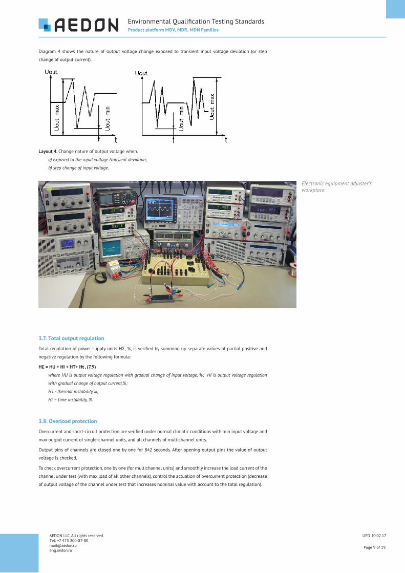
Diagram�4� shows� the� nature� of� output� voltage� change� exposed� to� transient� input� voltage� deviation� (or� step�
change�of�output�current).
Layout 4. Change�nature�of�output�voltage�when.
a) exposed to the input voltage transient deviation;
b) step change of input voltage.
3.7. Total output regulation
Total�regulation�of�power�supply�units�HΣ,�%,�is�verified�by�summing�up�separate�values�of�partial�positive�and�
negative�regulation�by�the�following�formula:
HΣ = НU + HI + HT+ Нt , (7.9)
where HU is output voltage regulation with gradual change of input voltage, %; HI is output voltage regulation
with gradual change of output current,%;
HT - thermal instability,%;
Нt – time instability, %.
3.8. Overload protection
Overcurrent�and�short-circuit�protection�are�verified�under�normal�climatic�conditions�with�min�input�voltage�and�
max�output�current�of�single-channel�units,�and�all�channels�of�multichannel�units.
Output�pins�of�channels�are�closed�one�by�one�for�8±2�seconds.�After�opening�output�pins�the�value�of�output�
voltage�is�checked.
To�check�overcurrent�protection,�one�by�one�(for�multichannel�units)�and�smoothly�increase�the�load�current�of�the�
channel�under�test�(with�max�load�of�all�other�channels),�control�the�actuation�of�overcurrent�protection�(decrease�
of�output�voltage�of�the�channel�under�test�that�increases�nominal�value�with�account�to�the�total�regulation).

UPD 10.02.17
Page 10 of 19.
AEDON LLC. All rights reserved. �Тel:�+7�473�200-87-80 [email protected] eng.aedon.ru
Environmental�Qualification�Testing�StandardsProduct platform MDV, MDR, MDN Families
3.9. Output overvoltage protection
Overvoltage�protection�of�the�first�channel�is�verified�under�normal�climatic�conditions�with�nominal�input�voltage�
and�min�output�current�of�single-channel�units,�and�all�channels�of�multichannel�units.
The�output�of�unit’s�first�channel�is�exposed�to�the�voltage�exceeding�the�nominal�1.5�times�from�an�additional�
power�supply.�Current�consumption�should�reduce�down�to�200mA�and�less.
3.10. No load operation
No�load�operation�of�units�is�checked�with�max�input�voltage.�The�unit�is�put�into�no�load�operation�mode�and�the�
output�voltage�of�each�channel�is�measured�(for�multi-channel�units).
3.11. Current
The�current�consumed�from�the�mains�at�the�time�of�power�on�of�power�supply�unit�is�checked�with�max�input�
voltage� and�max� output� current� for� single-channel� units,� and� all� channels� of�multi-channel� units.� Consumed�
current�is�checked�by�measuring�resistance�Rchan,�value�of�which�must�be�less�that�the�input�resistance�of�the�unit.
The�alteration�of�voltage�is�registered�at�resistance�Rchan,�Ohm,�at�the�time�of�unit�power�on�by�supplying�control�
signal�to�“ON”�pin,�then�the�max�value�Umax,�V,�is�defined,�and�the�value�of�at�the�time�of�power�on�Ip.on,�A,�is�
calculated�using�the�following�formula:
Ip.on=Umax / Rchan
3.12. Power
Full� power� consumption�of� power� supply�units� is� checked�with�nominal� input� input�voltage� and�max�output�
current�of�single-channel�units,�and�all�channels�of�multichannel�units.��Value�of�full�power�consumption�P,�W,�is�
determined�by�the�following�formula:
P=U•I,
where U is the value of the input voltage, V;
I is the value of the input current, A.
3.13. Efficiency
Efficiency�of� the�power�supply�units� is�verified�with�nominal� input�voltage�and�max�output�current�of� single-
channel�units,�and�all�channels�of�multi-channel�units.�Full�power�consumption�P,�W,�and�total�(for�multi-channel�
units)�output�power�Pout,�W�are�defined.�The�value�of�efficiency�is�determined�by�the�following�formula:
ƞ=Pout/P
3.14. Remote power off
Remote�power�off�is�of�the�power�supply�units�is�verified�with�nominal�input�voltage�and�max�output�current�of�
single-channel�units,�and�all�channels�of�multi-channel�units.
3.15. Parallel operation
Parallel�operation�of�power�supply�unit�verified�at�nominal� input�voltage�by�control�of�voltage�of� the�parallel�
operation�pin�and�alteration�of�the�output�voltage�when�supplying�voltage�to�the��parallel�operation�pin�from�an�
external�power�supply.�
Set�toggle�switches�S1,�S5�to�“ON”.�Set�toggle�switch�S6�to�position�“1”�and�using�resistors�R1,�R2,�set�the�max�
output�current�of�the�unit.�The�voltage�at�the�“PARAL”�output�pin�should�be�(2.0�±�0.2)VDC.
Set� the� load� current� to� 0.5•(Inmax+Inmin).� � Set� the� output� voltage� at� the� output� pin� of� the� adjusted� power�
supply�G3�to�0�VDC.�Set�the�toggle�switch�S4�to�“ON”.�Smoothly�increase�the�voltage�at�G3�power�supply�up�to�
(2.0�±�0.2)�VDC;�make�sure�that�the�output�voltage�increases�not�less�than�5%.
UPD 10.02.17
Page 11 of 19.
AEDON LLC. All rights reserved. �Тel:�+7�473�200-87-80 [email protected] eng.aedon.ru
Environmental�Qualification�Testing�StandardsProduct platform MDV, MDR, MDN Families
3.16. Output voltage setup
Verification�of� the� limits� of�manual� output�voltage� setup�of� power� supply�units.�The� limits� of�manual� output�
voltage� setup� is�verified�with�max�output� current,�min� and�max� set�values�of� output�voltage�by� rotating� the�
resistor�rotor�connected�between�pins�“ADJ”�and�“-OUT”�(to�increase)�or�“ADJ”�and�“+OUT”�(to�reduce)�output�
voltage.�Nominal�of�the�resistor�is�indicated�in�the�unit’s�technical�passport.
Adjustment�range�ΔUadj,�%,�is�determined�with�the�account�of�the�sign�according�to�the�following�formula:
ΔUadj = (Umax(min)–Un)/Un•100
where Umax. is the upper limit of output voltage setup; Umin. is the lower limit of the output voltage setup;
Un is the nominal output voltage, VDC.
4.�Control�of�compliance�to�the�requirements of�environmental�stabilityNumber�of�tested�units:�2�pcs�of�each�size
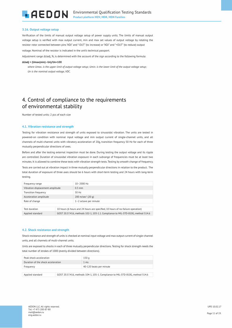
4.1. Vibration resistance and strength
Testing� for�vibration� resistance�and� strength�of�units� exposed� to� sinusoidal�vibration.�The�units� are� tested� in�
powered-on� condition� with� nominal� input� voltage� and� min� output� current� of� single-channel� units,� and� all�
channels�of�multi-channel�units�with�vibratory�acceleration�of�20g,�transition�frequency�50�Hz�for�each�of�three�
mutually�perpendicular�directions�of�axes.
Before�and�after�the�testing�external�inspection�must�be�done.�During�testing�the�output�voltage�and�its�ripple�
are�controlled.�Duration�of�sinusoidal�vibration�exposure�in�each�subrange�of�frequencies�must�be�at�least�two�
minutes.�It�is�allowed�to�combine�these�tests�with�vibration�strength�tests.�Testing�by�smooth�change�of�frequency.
Tests�are�carried�out�at�vibration�impact�in�three�mutually�perpendicular�directions�in�relation�to�the�product.��The�
total�duration�of�exposure�of�three�axes�should�be�6�hours�with�short-term�testing�and�24�hours�with�long-term�
testing.
Frequency�range 10–2000�Hz
Vibration�displacement�amplitude 0.3�mm
Transition�frequency 50�Hz
Acceleration�amplitude 200�m/sec2�(20�g)
Rate�of�change 1–2�octave�per�minute
Test�duration 10�hours�(6�hours�and�24�hours�are�specified,�10�hours�of�no-failure�operation)
Applied�standard GOST�20.57.416,�methods�102-1,�103-1.1.�Compliance�to�MIL-STD-810G,�method�514.6
4.2. Shock resistance and strength
Shock�resistance�and�strength�of�units�is�checked�at�nominal�input�voltage�and�max�output�current�of�single-channel�
units,�and�all�channels�of�multi-channel�units.
Units�are�exposed�to�shocks�in�each�of�three�mutually�perpendicular�directions.�Testing�for�shock�strength�needs�the�
total�number�of�strokes�of�1000�(evenly�divided�between�directions).
Peak�shock�acceleration 150�g
Duration�of�the�shock�acceleration 1 ms
Frequency 40-120�beats�per�minute
Applied�standard GOST�20.57.416,�methods�104-1,�105-1.�Compliance�to�MIL-STD-810G,�method�514.6

UPD 10.02.17
Page 12 of 19.
AEDON LLC. All rights reserved. �Тel:�+7�473�200-87-80 [email protected] eng.aedon.ru
Environmental�Qualification�Testing�StandardsProduct platform MDV, MDR, MDN Families
4.3. Single impacts
Exposure�to�single�impact�is�tested�in�powered-off�condition.��Units�are�exposed�to�tree�impacts�one�by�one�in�
each�direction�on�three�mutually�perpendicular�axes�(six�directions).
Peak�shock�acceleration 1000 g
Duration�of�action 0.5–2�ms
Applied�standard GOST�20.57.416,�methods�106-1.Partial�compliance�to�MIL-STD-810G,�method�514.6
4.4. High ambient temperature
Testing�of�exposure�to�high�ambient�temperature.�Absolute�humidity�of�air�in�the�chamber�must�not�exceed�an�
amount�equal�to�20�g�of�water�vapour�per�1�m3�of�air� (50%�at�35°C).�Before�testing�the�external�appearance,�
electrical� isolation� resistance,�established�deviation�of�output�voltage,�and�output�voltage� ripple�are�checked.�
Units�are�mounted�on�the�heatsink�(radiator)�with�base�thickness�at�least�10�mm�and�are�placed�in�a�chamber.�
Units�are�powered�on�at�nominal�input�voltage�and�max�output�current;�temperature�in�the�chamber�is�regulated�
so�that�unit’s�case�temperature�is�(90±2)�ºС�for�i-version�of�units,�and�(120±5)ºС�for�m-version.�
Test�duration:��after�the�setting�thermal�equilibrium�the�units�are�kept�in�powered-on�condition�within�2�hours,�
output�voltage�must�be�controlled.�Then,�without� removing� the�product� from�the�chamber�electrical� isolation�
resistance�established�output�voltage�deviation�and�output�voltage�ripple�are�checked.��Unit�are�removed�from�
the�chamber�and�exposed�to�normal�climatic�conditions�at�least�2�hours,�then�the�external�inspection�is�done�and�
controlled�parameters�are�verified.
Applied�standard GOST�20.57.406�method�201-2.2.�Compliance�to�MIL-STD-810G,�method�501.5
Climatic chambers.

UPD 10.02.17
Page�13�of�19.
AEDON LLC. All rights reserved. �Тel:�+7�473�200-87-80 [email protected] eng.aedon.ru
Environmental�Qualification�Testing�StandardsProduct platform MDV, MDR, MDN Families
4.5. Low ambient temperature
Testing�of�exposure�to�low�ambient�temperature.�Absolute�humidity�of�air� in�the�chamber�must�not�exceed�an�
amount�equal�to�20�g�of�water�vapour�per�1�m3�of�air� (50%�at�35°C).�Before�testing�the�external�appearance,�
electrical�isolation�resistance,�established�deviation�of�output�voltage,�and�output�voltage�ripple�are�checked.
If� necessary�units� are�mounted�on� the�heatsink� and� then�placed� in� chamber,� then� the� chamber� is� set� to� low�
temperature�-(60±3)ºС.��It�is�allowed�to�place�products�into�the�chamber�with�preset�temperature.�After�reaching�
thermal�equilibrium�units�are�kept�in�powered-on�condition�within�2�hours.�Then�electrical�isolation�resistance�is�
verified.�Units�are�powered�on�with�nominal�input�voltage�and�max�output�current.
Applied�standard GOST�20.57.406,�method�203.�Compliance�to�MIL-STD-810G,�method�502.5
4.6. Rapid ambient temperature change
Exposure� of� units� to� ambient� temperature� change� is� tested� by�method� of�“two� chambers”(rapid� temperature�
change).
The� external� appearance,� electrical� isolation� resistance,� established� deviation� of� output� voltage,� and� output�
voltage�ripple�are�checked�before�testing.
Units�are�placed�in�a�chamber�with�preset�low�temperature�(–60°С)�and�are�kept�in�powered-off�condition�during�
1�hour.�Then�units�are�moved�to�the�chamber�with�preset�high�temperature� (90±2)ºС,� for�units�of� i-version,�or�
(125±2)ºС�for�units�of�m-version,�and�are�kept�in�powered-off�condition�during�1�hour.�Total�number�of�cycles:�
three.
Transfer�time�must�be�the�shortest,�but�not�more�than�5�minutes.
After� completing� the� last� cycle�units� are�exposed� to�normal� climatic� conditions�during�2�hours�and� then� the�
external�appearance�and�electrical�isolation�resistance�are�checked.
Test�duration 1�hour,�3�cycles,�total�duration�6�hours
Applied�standard GOST�20.57.406�method�205-1
4.7. High humidity
Testing� of� exposure� to� high� humidity.� Before� testing� the� external� appearance,� electric� isolation� resistance,�
established�output�voltage�deviations,�and�output�voltage�ripple�are�verified.�
Testing�shall�be�carried�out� in�continuous�mode�(without�moisture�condensation).�Products�are�tested�without�
electrical�load.�The�products�are�placed�in�humidity�chamber.��The�temperature�inside�the�chamber�is�increased�
up�to�40�(55)ºС�and�the�units�are�exposed�to�this�temperature�during�2�days.��Relative�humidity�is�increased�up�
to�(93±3)%,�then�the�temperature�and�humidity�inside�the�chamber�are�kept�constant�during�56�(21)�days�with�
humidity�of�98%.

UPD 10.02.17
Page�14�of�19.
AEDON LLC. All rights reserved. �Тel:�+7�473�200-87-80 [email protected] eng.aedon.ru
Environmental�Qualification�Testing�StandardsProduct platform MDV, MDR, MDN Families
Units�are�removed�from�the�chamber�and�exposed�to�normal�climatic�conditions�during�at�least�2�hours,�then�the�
external�appearance,�electric�isolation�resistance,�established�output�voltage�deviation�and�output�voltage�ripple�
are�checked.�
Test�duration 21�day
Applied�standard GOST�20.57.406�method�207-2
4.8. Low atmospheric pressure
Testing�of�units�for�exposure�to�low�atmospheric�pressure.�Units�are�placed�in�chamber�and�exposed�to�pressure�
reduced�down�to�0,67•103�Pa�(5�mm�Hg)�during�1�hour.�Units�are�switched�on�with�nominal�input�voltage�and�
min�output�current�of�single-channel�units�and�all�channels�of�multi-channel�units,�kept�in�powered-on�condition�
during�30�minutes,�then�the�established�output�voltage�deviation�and�output�voltage�ripple�are�measured.�Power�
off�the�units.�Pressure�in�chamber�in�increased�up�to�normal.�
Max.�operation�altitude�—�35�km�above�sea�level�(based�on�the�value�of�allowable�low�pressure).
Applied�standard GOST�20.57.406�method�209-1
4.9. High atmospheric pressure
Testing�of�units�for�exposure�to�high�atmospheric�pressure.�Units�are�placed�in�chamber;�the�chamber�pressure�is�
increased�up�to�2.92�•�105�Pa�(2207�mm�Hg)�and�exposed�during�4�hours.�Units�are�switched�on�with�input�voltage�
and�min�output�current�of�single-channel�units,�and�all�channels�of�of�multi-channel�units,�kept�in�powered-on�
condition�during�1�hour,�then�the�established�deviation�of�output�voltage,�and�output�voltage�ripple�are�checked.�
Power�off�the�units.�The�pressure�in�the�chamber�is�lowered��down�to�normal.
Test�duration In�powered-off�condition�—�4�hours,�in�powered-on�condition�1�hour.
Applied�standard GOST�20.57.406�method�210-1
4.10. Radio interference voltage
Radio�interference�level�of�power�supply�units�is�checked�according�to�MIL-461�methods�for�CE102�requirements.
4.11. Precipitation
Condensed�atmospheric�precipitation�(frost,�dew).�Products�in�the�powered-on�condition�are�placed�in�the�cold�
chamber�which�is�set�to�-(25±3)°С�and�exposed�during�2�hours.
Products�are�removed�from�the�camera�and�exposed�to�normal�climatic�conditions,�and�supplied�with�electric�
voltage.�The�products�are�kept�In�powered-on�condition�during�3�hours.
Test�duration 2�hours�������3�hours
Complies�to� MIL-STD-810G�method�521.3�by�value�VF.

UPD 10.02.17
Page�15�of�19.
AEDON LLC. All rights reserved. �Тel:�+7�473�200-87-80 [email protected] eng.aedon.ru
Environmental�Qualification�Testing�StandardsProduct platform MDV, MDR, MDN Families
4.12. Salt fog (marine)
Product� exposure� to� salt� fog� with� periodic� spraying� of� salt� solution.� Salt� solution� is� prepared� by� dissolving�
sodium�chloride�in�distilled�water.�Hydrogen-ion�concentration�(pH)�of�the�solution�should�be�within�6.5-7.2�at�
temperature�of�(20�±�2)°C�and,�if�necessary,�it�must�be�corrected�to�this�level�by�adding�dilute�hydrochloric�acid�
(Hcl)�or�sodium�hydroxide.�Error�in�determining�the�pH�should�not�exceed�0.1�pH.
The�product�is�exposed�to�normal�climatic�conditions�during�two�days.�The�temperature�in�the�chamber�is�set�
to�(27�±�2)°С�and�the�products�are�exposed�to�salt�fog.�Salt�fog�must�have�such�dispersiveness�and�fog�water�to�
reach�the�amount�of�condensate,�averaged�during�16�hour�chamber�operation,�to�0.1-0.3�ml/hour�for�each�80cv2�
of�horizontal�surface�of�the�testing�are.
The�solution�us�sprayed�during�15�minutes�every�45�minutes�of�exposure.
Products�are�washed�in�distilled�water�at�temperature�of�35-40°C�with�full�immersion�of�products�in�water�and�
shaking�them�for�1�minute.�Then�the�product�is�dried�during�2�hours�at�55°C�and�visually�inspected.
Test�duration 2�days
Applied�standard GOST�20.57.416,�methods�215-2,�215-3.�Compliance�to�MIL-STD-810G,�method�509.5
4.13. Static dust (sand)
Products�are�placed�in�chamber�and�the�temperature�is�set�to�(60�±�3)°C.�Relative�humidity�of�air�—�not�more�than�
25%.�The�product�is�blown�by�dust-sand�mix,�20%�of�chalk�and�20%�of�kaolin,�passing�through�a�sieve�with�mesh,�
during�2�hours.�Then�the�fan�is�turned�off�during�2�hours�the�dust�deposits�without�air�circulation.
Particle�size�of�dust�mix 150�g
Remnants�of�particles�not�sifted�through�the�sieve 1 ms
Speed�of�air�circulation�in�Chamber�before�the�dust��starts�depositing
40–120�beats�per�minute
Concentration�of�dust 2�g/m3�or�0.1%�of�usable�volume�of�chamber
Test�duration 4�hours
Applied�standard —

UPD 10.02.17
Page�16�of�19.
AEDON LLC. All rights reserved. �Тel:�+7�473�200-87-80 [email protected] eng.aedon.ru
Environmental�Qualification�Testing�StandardsProduct platform MDV, MDR, MDN Families
1.�Compliance� to� the� requirements�of� reliability�of�units� is�controlled�by�short-term�and� long-term�testing� for�
failure-free�operation�with�estimation�of�failure-free�operation�indices�based�on�generalization�of�testing�results,�
including�shelf-life�testing.�
Testing� is� carried� by� two� cycles� with� max� input� voltage� and� max� output� current.� Duration� of� each� cycle�—�
250�hours.
2.�Short-term�failure-free�operation�testing�performed�during�500�hours.�In�the�process�of�testing�every�100�hours�
the�deviation�and�ripple�of�output�voltage�is�checked.
3.� Long-term� failure-free� operation� testing� continues� the� short-term� failure-free� operation� testing� within�
qualification�testing.���During�and�after�the�testing�the�units�are�visually�inspected,�output�voltage,�ripple,�thermal�
and�time�instability�of�output�voltage�are�measured.�Criteria�parameters�of�validity�are�controlled�during�testing�
every�1000�hours�during�first�10�000�hours,�then�—�every�5000�hours.
5.�Reliability�compliance�control
Mechanical and climatic factors Exposure time in one cycle, hRepeated�shock�loads�with�speed�from�40�to�120�beats�per�minute
0,5
Vibration�loads 10
High�temperature 60
Low�temperature 4
High�humidity 60
Temperature�cycling 6
Normal�conditions 110
Reliability test cycle at high temperature.

UPD 10.02.17
Page 17 of 19.
AEDON LLC. All rights reserved. �Тel:�+7�473�200-87-80 [email protected] eng.aedon.ru
Environmental�Qualification�Testing�StandardsProduct platform MDV, MDR, MDN Families
6.�Testing�and�control�of�DC/DC�converters�in�production�100%�of�products�undergo�repeated�testing�and�quality�control,�ongoing�throughout�whole�production�process.�
The�main�aim�is�to�control�the�quality�of�manufactured�products�and�assurance�of�best�reliability.��Each�product�in�
the�course�of�technological�cycle�undergoes�the�quality�control�operations�specified�below.�
6.1. Control of surface mounting by automatic optical inspection
Control�is�carried�out�immediately�after�the�operation�of�surface�mounting,�using�automated�optical�inspection.��
Points�to�control:�location�of�all�elements�mounted�on�PCB�surface,�correctness�of�nominal�values�of�mounted�
elements,�quality�of�soldered�joints�with�obligatory�control�of�shape�and�height�of�hollows�of�soldered�joints.
6.2. QCD inspection of soldered joints quality of air and surface mounting by automatic optical inspection
Factory’s�QCD�carries�control�using�automatic�optical� inspection�of�PCBs�after�mounting�all�necessary�electric�
components.� �Automatic� inspection�allows� to�discover�all�possible� soldering�defects�of� surface�mounting�and�
components�that�are�soldered��in�holes�of�PCB.��
6.3. Control of electric parameters during production
During�production�of�power�supply�units�electric�parameters�are�checked�upto�three�times.
First� testing� of� electric� parameters� and� the� required� adjustment� of� product� parameters� is� performed� after�
mounting�of�all�necessary�elements�on�the�PCB.�
Electric�parameters�are�measured�using�contemporary�highly�accurate�measuring�equipment.
The�second� testing� is�performed�after� the�complete�of�assembly�of� the�product.�Basic�electric�parameters�are�
registered�and�recorded�in�the�product’s�protocol�and�in�factory’s�database.�
Final�testing�of�products’�electrical�parameters�at�production�sites�is�performed��after�filling�of�the�product�with�
polymer�compound.
6.4. QCD inspection of product assembly accuracy
After� full�product�assembly�and�mounting� it� in�a�case� that�QCD�controls�by�visual� inspection� the�accuracy�of�
assembly�based�on�factory’s�quality�standards.�
6.5. Isolation resistance test
Additional�control�of�assembly�quality�and�mounting�is�the�measurement�of�isolation�resistance�of�products,�that�
allows�to�avoid�assembly�errors.
Automated stand with the output of parameters to the PC.
Automatic optical inspection.

UPD 10.02.17
Page�18�of�19.
AEDON LLC. All rights reserved. �Тel:�+7�473�200-87-80 [email protected] eng.aedon.ru
Environmental�Qualification�Testing�StandardsProduct platform MDV, MDR, MDN Families
6.6. Operation test of products at the lowest temperature of the operating temperature range
Operational� control� of� products� and� conformity� of� electrical� parameters� after� exposure� to� cold� in� chamber.�
Electrical�parameters�are�measured�at�a�temperature�corresponding�to�the�the�lower�limit�of�the�temperature�
range�specified�in�the�product’s�Specifications.
6.7. Long-term tests of powered-on units at max operating temperature measuredon product case
Product�reliability�and�stability�of�electrical�parameters�are�monitored�at�continuous�operation�of�products�with�
heating�up�to�upper�limit�of�high�temperatures�of�product’s�case.�During�testing�the�units�are�placed�in�special�
heating�stands.�Electric�parameters�are�monitored�during�the�comlete�cycle�of�temperature�test.
6.8. Isolation resistance test
In�order�to�ensure�compliance�with�the�stated�safety�requirements,�the�product’s�isolation�resistance�breakdown�
test�is�performed�by�50�Hz�test�AC�voltage.��Verification�is�performed�at�final�production�stages�using�universal�
breakdown�tester.
6.9. Electric parameters verification by factory QCD
Before� passing� the� product� to� packaging� quality� officers� measure� again� all� electric� parameters� regulated�
by�technical�requirements�for�a�given�type�of�product.�
6.10. External inspection of the product, accompanying documents set and accuracy of packing
Before�passing�the�product� to� the�finished�store�the�products�appearance� is�checked�and�verified�for�absence�
of� case� defects,� completeness� of� documentation� and� correctness� of� overall� dimensions.� Comleteness,� quality�
and��appearance�of�packing�are�checked.
Long testing of units at max operating temperature.

UPD 10.02.17
Page 19 of 19.
AEDON LLC. All rights reserved. �Тel:�+7�473�200-87-80 [email protected] eng.aedon.ru
AEDON,�LLC�is�the�leading�Russian�developer and�manufacturer�of�DC/DC�converters�and�power supply�systems�for�critical�applications.
eng.aedon.ru [email protected]
Druzinnikov�str.�1,�Voronezh 394026,�Russia�
+7�473�200-87-80
1,�bld.�2,�BC�“W�Plaza�1”, office�A403,�Moscow 101000,�Russia�
+7�499�372-50-10�