Embed Size (px)
Citation preview
Quality Assurance Project Plan
Performance Assessment Model
Clive, Utah
Prepared by
Neptune and Company 1505 15th St Suite B Los Alamos, NM 87544
Document No: 06245-001
APPROVALS ________________________________ ___________
Paul Black Date Neptune and Company Project Manager
________________________________ ___________
James Markwiese Date Neptune and Company Corporate Quality Assurance Officer
Contents
1.0 INTRODUCTION ......................................................................................................................... 1
2.0 PROJECT MANAGEMENT AND ORGANIZATION............................................................... 1
3.0 PERSONNEL QUALIFICATIONS AND TRAINING .............................................................. 2
4.0 PROJECT DESCRIPTION .......................................................................................................... 3
5.0 CRITICAL TASKS AND SCHEDULE ........................................................................................ 4
6.0 QUALITY OBJECTIVES AND MODEL PERFORMANCE CRITERIA ................................ 5
7.0 DOCUMENTATION AND RECORDS ....................................................................................... 6
8.0 DATA ACCEPTANCE CRITERIA ............................................................................................... 6
9.0 DATA MANAGEMENT AND SOFTWARE CONFIGURATION ............................................ 7
10.0 MODEL ASSESSMENT AND RESPONSE ACTIONS ............................................................ 7
11.0 MODEL REQUIREMENTS ASSESSMENT ............................................................................. 8
Figures
Figure 1: N&C Organizational Chart ..................................................................................... 2
Tables
Table 1: Roles, Responsibilities, and Training ................................................................... 3 Table 2: Critical tasks for meeting project objectives, task products, and
scheduled completion dates. ................................................................................. 4
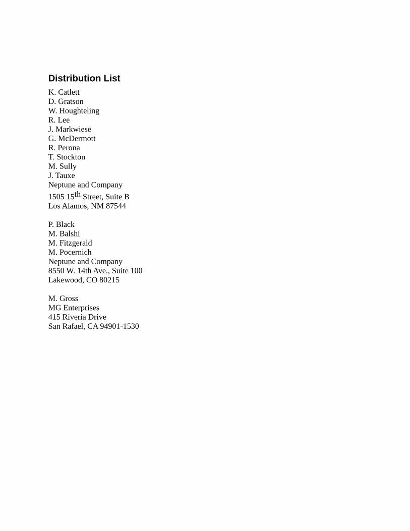
Distribution List K. Catlett D. Gratson W. Houghteling R. Lee J. Markwiese G. McDermott R. Perona T. Stockton M. Sully J. Tauxe Neptune and Company 1505 15th Street, Suite B Los Alamos, NM 87544 P. Black M. Balshi M. Fitzgerald M. Pocernich Neptune and Company 8550 W. 14th Ave., Suite 100 Lakewood, CO 80215 M. Gross MG Enterprises 415 Riveria Drive San Rafael, CA 94901-1530
Quality Assurance Project Plan: Clive Performance Assessment Model
1.0 Introduction This document describes the quality assurance project plan (QAPP) for modeling services provided for the development of a performance assessment model for the disposal of depleted uranium by EnergySolutions at the Clive, Utah facility. Throughout this document, the term Quality Assurance (QA) refers to a program for the systematic monitoring and evaluation of the various aspects of performance assessment model development to ensure that the models and analyses are of the type and quality of that needed and expected by the client.
2.0 Project Management and Organization Neptune and Company (N&C) has developed this QAPP for conducting work for EnergySolutions under purchase order 008404. This QAPP is based on the Environmental Protection Agency (EPA) QA/G-5M Guidance for Quality Assurance Project Plans for Modeling, and our company’s nineteen year history working in the environmental quality arena. A tiered approach is used that includes specific procedures developed by N&C that have been developed for modeling projects. This project-specific QAPP will work as an umbrella plan that ensures quality across all tasks.
The N&C quality program includes:
• Experienced and trained personnel who understand the QA requirements of each task.
• An experienced Project Manager.
• A corporate Quality Assurance Officer
• Task planning, tracking, and operation via internal SOPs.
• Emphasis on continuous improvement via internal reviews and customer feedback.
It is the policy of N&C to implement a quality program designed to generate products or services that meet or exceed the expectations established by our clients. This quality policy addresses all products delivered to our EnergySolutions client under the contract. We will ensure quality through the use of a quality program that includes program and project management, systematic planning, work and product assessment and control along with continuous improvement to ensure that data and work products of acceptable quality to support the intended use are produced.
To achieve this goal, N&C will assign appropriately qualified and trained staff and ensure that all products are carefully planned. Tasks will be conducted according to the QAPP or applicable SOP and any and all problems affecting quality will be brought to the immediate attention of the project or task manager for resolution. All products will be reviewed by another technical expert. Adequate budget and time will be planned to execute the quality system.
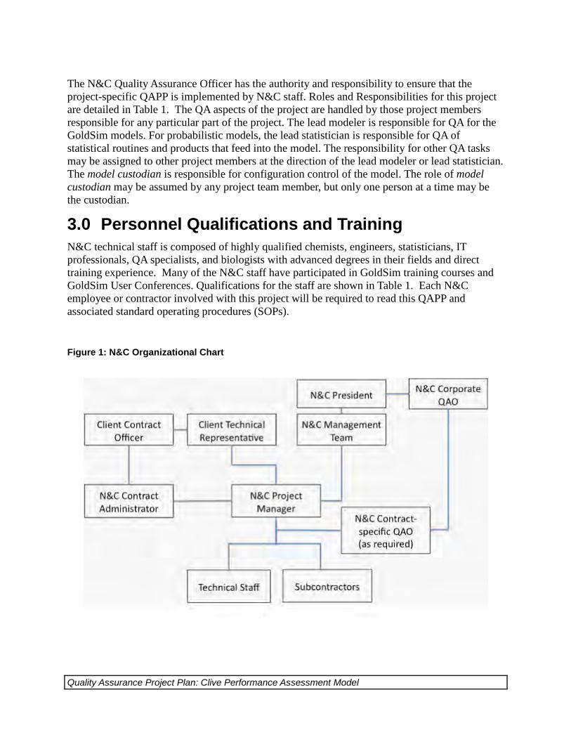
As indicated on Figure 1, the N&C organizational structure ensures direct reporting between the N&C Project QA Officer and the Project Manager. This structure requires that all N&C technical staff report to the N&C Project Manager who is responsible for the work.
Quality Assurance Project Plan: Clive Performance Assessment Model
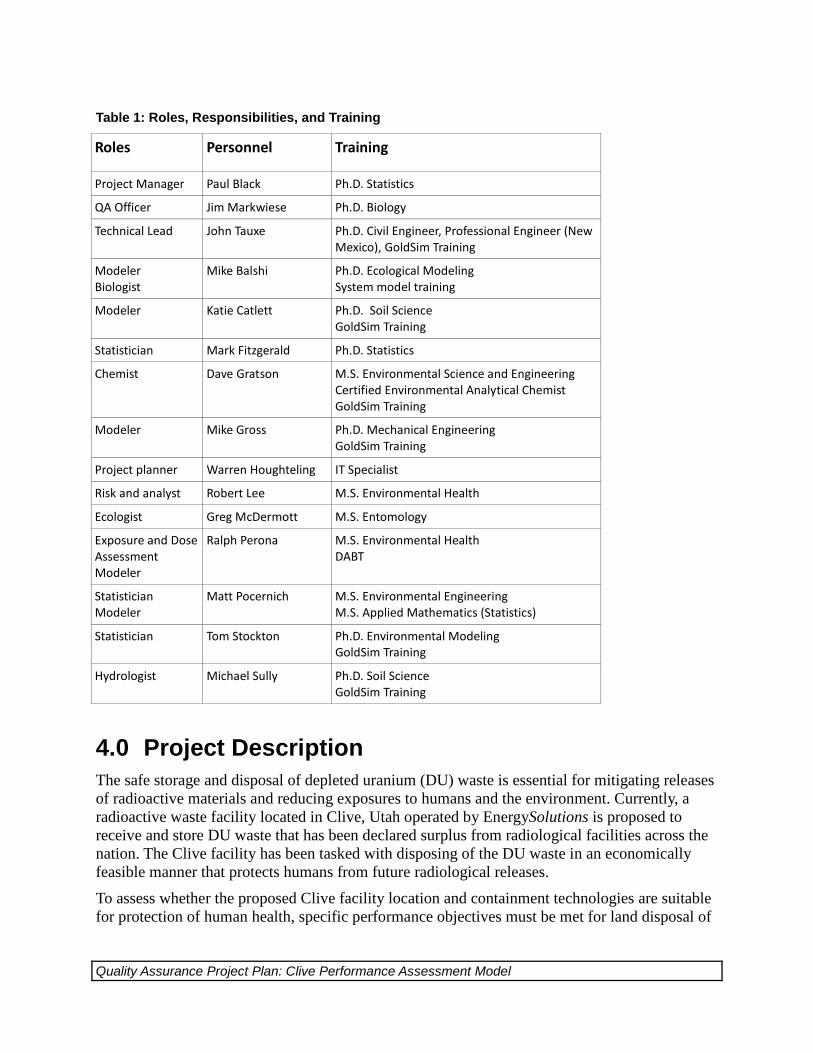
The N&C Quality Assurance Officer has the authority and responsibility to ensure that the project-specific QAPP is implemented by N&C staff. Roles and Responsibilities for this project are detailed in Table 1. The QA aspects of the project are handled by those project members responsible for any particular part of the project. The lead modeler is responsible for QA for the GoldSim models. For probabilistic models, the lead statistician is responsible for QA of statistical routines and products that feed into the model. The responsibility for other QA tasks may be assigned to other project members at the direction of the lead modeler or lead statistician. The model custodian is responsible for configuration control of the model. The role of model custodian may be assumed by any project team member, but only one person at a time may be the custodian.
3.0 Personnel Qualifications and Training N&C technical staff is composed of highly qualified chemists, engineers, statisticians, IT professionals, QA specialists, and biologists with advanced degrees in their fields and direct training experience. Many of the N&C staff have participated in GoldSim training courses and GoldSim User Conferences. Qualifications for the staff are shown in Table 1. Each N&C employee or contractor involved with this project will be required to read this QAPP and associated standard operating procedures (SOPs).
Figure 1: N&C Organizational Chart
Quality Assurance Project Plan: Clive Performance Assessment Model
Table 1: Roles, Responsibilities, and Training
Roles Personnel Training
Project Manager Paul Black Ph.D. Statistics
QA Officer Jim Markwiese Ph.D. Biology
Technical Lead John Tauxe Ph.D. Civil Engineer, Professional Engineer (New Mexico), GoldSim Training
Modeler Biologist
Mike Balshi Ph.D. Ecological Modeling System model training
Modeler Katie Catlett Ph.D. Soil Science GoldSim Training
Statistician Mark Fitzgerald Ph.D. Statistics
Chemist Dave Gratson M.S. Environmental Science and Engineering Certified Environmental Analytical Chemist GoldSim Training
Modeler Mike Gross Ph.D. Mechanical Engineering GoldSim Training
Project planner Warren Houghteling IT Specialist
Risk and analyst Robert Lee M.S. Environmental Health
Ecologist Greg McDermott M.S. Entomology
Exposure and Dose Assessment Modeler
Ralph Perona M.S. Environmental Health DABT
Statistician Modeler
Matt Pocernich M.S. Environmental Engineering M.S. Applied Mathematics (Statistics)
Statistician Tom Stockton Ph.D. Environmental Modeling GoldSim Training
Hydrologist Michael Sully Ph.D. Soil Science GoldSim Training
4.0 Project Description The safe storage and disposal of depleted uranium (DU) waste is essential for mitigating releases of radioactive materials and reducing exposures to humans and the environment. Currently, a radioactive waste facility located in Clive, Utah operated by EnergySolutions is proposed to receive and store DU waste that has been declared surplus from radiological facilities across the nation. The Clive facility has been tasked with disposing of the DU waste in an economically feasible manner that protects humans from future radiological releases.
To assess whether the proposed Clive facility location and containment technologies are suitable for protection of human health, specific performance objectives must be met for land disposal of
Quality Assurance Project Plan: Clive Performance Assessment Model
radioactive waste set forth in Title 10 Code of Federal Regulations Part 61 (10 CFR 61) Subpart C, and promulgated by the Nuclear Regulatory Commission (NRC). In order to support the required radiological performance assessment (PA), a detailed computer model will be developed to evaluate the doses to human receptors that would result from the disposal of DU and its associated radioactive contaminants (collectively termed “DU waste”), and conversely to determine how much DU waste can be safely disposed at the Clive facility.
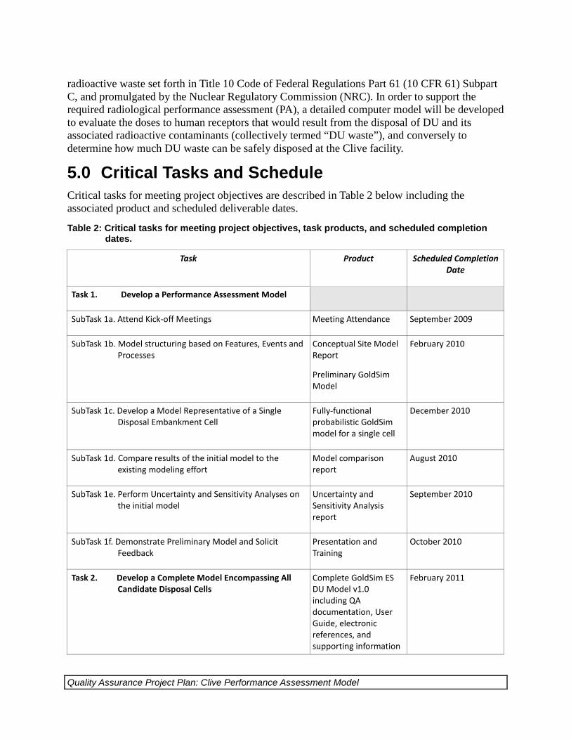
5.0 Critical Tasks and Schedule Critical tasks for meeting project objectives are described in Table 2 below including the associated product and scheduled deliverable dates.
Table 2: Critical tasks for meeting project objectives, task products, and scheduled completion dates.
Task Product Scheduled Completion Date
Task 1. Develop a Performance Assessment Model
SubTask 1a. Attend Kick-off Meetings Meeting Attendance September 2009
SubTask 1b. Model structuring based on Features, Events and Processes
Conceptual Site Model Report
Preliminary GoldSim Model
February 2010
SubTask 1c. Develop a Model Representative of a Single Disposal Embankment Cell
Fully-functional probabilistic GoldSim model for a single cell
December 2010
SubTask 1d. Compare results of the initial model to the existing modeling effort
Model comparison report
August 2010
SubTask 1e. Perform Uncertainty and Sensitivity Analyses on the initial model
Uncertainty and Sensitivity Analysis report
September 2010
SubTask 1f. Demonstrate Preliminary Model and Solicit Feedback
Presentation and Training
October 2010
Task 2. Develop a Complete Model Encompassing All Candidate Disposal Cells
Complete GoldSim ES DU Model v1.0 including QA documentation, User Guide, electronic references, and supporting information
February 2011
Quality Assurance Project Plan: Clive Performance Assessment Model
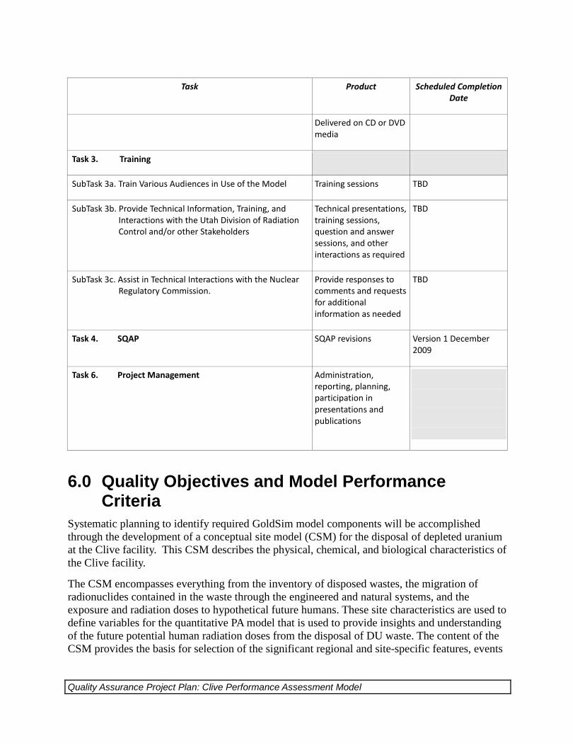
Task Product Scheduled Completion Date
Delivered on CD or DVD media
Task 3. Training
SubTask 3a. Train Various Audiences in Use of the Model Training sessions TBD
SubTask 3b. Provide Technical Information, Training, and Interactions with the Utah Division of Radiation Control and/or other Stakeholders
Technical presentations, training sessions, question and answer sessions, and other interactions as required
TBD
SubTask 3c. Assist in Technical Interactions with the Nuclear Regulatory Commission.
Provide responses to comments and requests for additional information as needed
TBD
Task 4. SQAP SQAP revisions Version 1 December 2009
Task 6. Project Management Administration, reporting, planning, participation in presentations and publications
6.0 Quality Objectives and Model Performance Criteria
Systematic planning to identify required GoldSim model components will be accomplished through the development of a conceptual site model (CSM) for the disposal of depleted uranium at the Clive facility. This CSM describes the physical, chemical, and biological characteristics of the Clive facility.
The CSM encompasses everything from the inventory of disposed wastes, the migration of radionuclides contained in the waste through the engineered and natural systems, and the exposure and radiation doses to hypothetical future humans. These site characteristics are used to define variables for the quantitative PA model that is used to provide insights and understanding of the future potential human radiation doses from the disposal of DU waste. The content of the CSM provides the basis for selection of the significant regional and site-specific features, events
Quality Assurance Project Plan: Clive Performance Assessment Model
and processes that need to be represented mathematically in the PA model. A report describing the CCM will be developed as part of Task 1.
As described in Section 4.0 the objective of the PA is to provide a tool for determining if specific performance objectives will be met for land disposal of radioactive waste set forth in Title 10 Code of Federal Regulations Part 61 (10 CFR 61) Subpart C, and promulgated by the Nuclear Regulatory Commission (NRC). The quality objective for the model is to provide results that are consistent with the site characteristics, the waste characteristics, and the CSM. If data are available, the demonstration of consistency will be supported by available site monitoring data and other field investigations. The model predictions of transport of radionuclides and the inadvertent intrusion into the disposal facility, and the sensitivity and uncertainty of the calculated results should be comprehensive representations of the existing knowledge of the site and the disposal facility design and operations.
7.0 Documentation and Records Subversion version-control software will be used to maintain records of ownership and traceability of all project-specific files and database contents. Original data are stored in version-controlled repositories. Additions, deletions and file modifications within the repository are tracked by the version control software, which documents the file user and the date and time of modification. The version control software also offers a “compare between revisions” feature for text files that denotes line-by-line changes between previous and current versions of a file. User-entered comments are also maintained by the version control software as files are added, deleted, or modified. Version control of records is described in more detail in the EnergySolutions Subversion SOP in Appendix A.
Internal documentation of the GoldSim model, version change notes, change log, model versioning, and model error reporting and resolution are described in the EnergySolutions GoldSim Model Development SOP in Appendix B and the EnergySolutions Issue Tracker SOP in Appendix C.
8.0 Data Acceptance Criteria The choice of data sources depends on data availability and data application in the model. The following hierarchy outlines different types of information and their application. The information becomes increasingly site-specific and parameter uncertainty is generally reduced moving down the list.
• Physical limitations on parameter ranges, used for bounding values when no other supporting information is available. Example: Porosity must be between 0 and 1 by definition.
• Generic information from global databases or review literature, used for bounding values and initial estimates in the absence of site-specific information. Example: A common value for porosity of sand is 0.3.
Quality Assurance Project Plan: Clive Performance Assessment Model
• Local information from regional or national sources, used to refine the above distributions, but with little or no site-specific information. Example: Sandy deposits in the region have been reported to have porosities in the range of 0.30 to 0.37, based on drilling reports.
• Information elicited from experts regarding site-specific phenomena that cannot be measured. Example: The likelihood of farming occurring on the site sometime within the next 1000 years is estimated at 50% to 90%.
• Site-specific information gathered for other purposes. Example: Water well drillers report the thickness of the regional aquifer to be 10 to 12 meters.
• Site-specific modeling and studies performed for site-specific purposes. Example: The infiltration of water through the planned engineered cap is estimated by process modeling to be between 14 and 22 cm/yr.
• Site-specific data gathered for specific purposes in the models. Example: The density of Pogonomyrmex ant nests adjacent to the site is counted, and found to be 243 nests per hectare.
The determination of data adequacy is informed by a sensitivity analysis of the model, which identifies those parameters most significant to a given model result. Such parameters are candidates for improved quality. As the model development cycle proceeds, sensitive parameters are identified, and their sources are evaluated to determine the cost/benefit of reducing their uncertainty.
9.0 Data Management and Software Configuration The acquired data, developed statistical distributions and results generated by the GoldSim model and the uncertainty and sensitivity analyses will be archived in a version-control repository as described in Section 7.0 above. Configuration management for the GoldSim model is described in the EnergySolutions GoldSim SOP in Appendix B.
10.0 Model Assessment and Response Actions During model development assessments will be conducted using a graded approach with the level of testing proportional to the importance of the model feature. Assessments will consist of:
• reviews of model theory
• reviews of model algorithms
• reviews of model parameters and data
• sensitivity analysis
• uncertainty analysis
Quality Assurance Project Plan: Clive Performance Assessment Model
• tests of individual model modules using alternate methods of calculation such as analytic solutions or spreadsheet calculations
• reasonableness checks
Response actions including error reporting and resolution processes are described in the EnergySolutions GoldSim SOP and the EnergySolutions Issue Tracker SOP.
11.0 Model Requirements Assessment The purpose of these assessments is to confirm that the modeling process was able to produce a model that meets project objectives. Model results will be reviewed to ensure that results are consistent with the site characteristics, the waste characteristics, and the CSM as described in Section 6.0. Model results will be assessed to determine that the requirements of EnergySolutions for the use of the model have been met. Any limitations on the use of the model results will be reported to the project manager and discussed with EnergySolutions.

Appendix A - EnergySolutions Subversion Standard Operating Procedure
1
Neptune and Company (N&C) Internal Procedure Confidential
General Procedure: Standard Operating Procedure (SOP) Contract Specific: Internal N&C product
Document No. 06245-002
Version: 01
Document Status: Final
Title: EnergySolutions Subversion SOP Author: Warren Houghteling
Revised by: N/A
Final Approval Signatures Date
Corporate Quality Assurance Officer: Print Name: James Markwiese Signature:
12/21/1010
Neptune and Company Project Manager Print Name: Paul Black Signature:
12/21/2010
Effective Date: 12/21/2010 Page 1 of 11
Date Stamp: 2/22/2011
2
EnergySolutions Subversion SOP
Introduction Subversion is an open source version control system. Version control is the management of changes to documents, programs, and other information stored as electronic files. Neptune uses subversion to manage work products and other project information that can be stored as electronically. Subversion has two major features that support increased productivity and better Quality Assurance:
1) Subversion allows the easy sharing of file in a way that allows all project participants to have access to the latest version of the file. No longer is it necessary to send emails back and forth with updates to work products, a process which can often lead to confusion as to which document version contains all the latest changes
2) Subversion keeps a copy of every “committed” version of the file in its database, making it easy to go back to earlier versions of a file. No file version is ever deleted in subversion. The progression of changes in any file can be tracked via the comment feature, which allows the user to add a comment describing what had changed each time they commit an edited version of a file to the database.
Repositories As the Subversion online manual (http://svnbook.red-bean.com/) states, Subversion is a centralized system for sharing information. At its core is a repository, which is a central store of data. The SVN repositories live on a central server, SVN.neptuneinc.org. New repositories can be created on the server at any time. To the user, a repository appears as a collection of files and directories (although they are not actually stored that way on the SVN server). Users access the contents of a repository by “checking out” a local copy of the repository. This process copies files from the repository to the user’s computer, creating a local “working copy” of the repository. The user can then make changes to their local copy and “commit” these changes back to the repository, so they become part of the centralized data store. To get the latest changes committed by others, the user should periodically “update” their repository, a process which pulls down any new changes from the server that are not yet part of the user’s working copy. Repositories have typically been created on a per-project basis, but some have instead been created to house all the data associated with a particular client (for example, the EPA repository). The latter approach produces very large repositories,
3
which can make downloading the whole repository very time consuming, especially for users outside the Los Alamos office where the server resides. However, this can be worked around by the user checking out only the sub-folders they need from a given repository. This will be discussed in more detail later in this document.
Accessing Repositories To access Neptune’s subversion repositories, you will need two things:
1) a subversion user account on the server 2) a client program running on your computer which can interact with the
subversion server to allow you to check out, update, and commit files
Obtaining a Subversion Account This should be done automatically as part of your new-employee setup; however, if for some reason you find yourself without an account, any member of the IT team can set you up with one. You will receive a username and a password, which need to be submitted for most SVN transactions. Fortunately, all SVN clients provide the opportunity to cache your identity so that you do not have to repeatedly enter your credentials.
Subversion Clients
Windows GUI On Windows machines, the main client we use is Tortoise SVN, which is available from Tigris.org. Its home page is http://tortoisesvn.tigris.org/. Downloading and installing Tortoise SVN is a straightforward process, but IT staff will always be glad to offer assistance if needed. Tortoise works as a plugin to Windows Explorer (NOT Internet Explorer the web browser, but the file explorer); once you have Tortoise installed, you will see special icons next to files that are part of working copies, and you will have access to SVN commands via right-clicking on any file or folder in Windows Explorer. Other clients are available – the other client that software developers use is a plugin to the Eclipse development environment called Subclipse (also from Tigris).
4
Mac GUI There are two main Mac clients currently in use at Neptune, SCplugin (http://scplugin.tigris.org/) , which mimics some of the Tortoise functionality but unfortunately does not have all features enabled on the latest OS version (Snow Leopard), and svnX (http://www.lachoseinteractive.net/en/community/subversion/svnx/), which has a richer feature set but a very different UI concept. Both clients are useful and can even coexist on the same machine. As is the case on Windows, plugins are also available for various development environments (e.g. Netbeans, Eclipse).
Command Line On Linux and other Unix-based systems (including the Mac), there is a command-line client program called SVN. The command line client is the most flexible and powerful way to interact with subversion, and may be needed in special situations to address issues that the GUI clients cannot handle. In these cases, IT personnel can lead you through the necessary steps.
Getting Started with Subversion Your first experience with subversion will likely involve someone on your project team telling you to check out a repository (or sub-section of a repository) so you can examine and/or modify files. You will need the URL of the repository (or sub-directory) to be able to check it out. All Neptune SVN URLs will begin with http://SVN.neptuneinc.org/repos followed by the repository name. So if I wanted to check out the entire Neptune repository (not recommended, as it is very large), I would use the URL http://SVN.neptuneinc.org/repos/neptune.
Trunk, Branches, and Tags Most repositories have three top-level directories called trunk, branches, and tags. The trunk represents the main line of work in the repository – the branches and tags folders have specialized uses, which will be discussed later (they are mainly relevant to programmers). When someone asks you to check out the “project1” repository, and that repository has a trunk, the URL you will want to use is http://SVN.neptuneinc.org/repos/project1/trunk. However, the name of the directory you will create to check the files out into should be called project1, so you will know what repository you are working with.
5
Checking Out Once you have been given the URL of the repository you want to check out, you will enter that URL into your subversion client as part of a “checkout” operation. Depending on you client, you may need to create the containing directory first, or the client may do it for you if you indicate a directory that does not yet exist. Either way, the files you have requested will be copied from the SVN server to the location you have specified. Subversion does NOT CARE where on your machine you chose to store your files. Subversion keeps hidden “metadata” folders inside each folder of your working copy. One of the things these metadata folders keep track of is what URL on the server the current directory corresponds to. This means that you can move the location of the working copy on your computer, and this will not affect subversion at all – it still knows where to go on the server to get updates for those files, or commit changes to those files If the repository is large, and especially if you are not in the Los Alamos office where the SVN server resides, this initial checkout could take a long time. Your client will show you a running progress display, usually listing each file that is pulled down from the server. If the listing seems to get “stuck” on a particular file, that probably means that the next file in the list is very large, as the files are not listed until their download is complete. Occasionally, you will some kind of “timeout” error message during a long checkout. In this case, it almost always works to simply update your working copy to get the rest of the files (see the next section for updating).
Updating As time passes, other team members may make changes to files in the repository you have checked out. The only way for you to see these changes to update your working copy of the repository. Your SVN client will allow you to select any directory or file in a working copy and request that it be updated. Usually, you will want to pick the top-level directory, so you can get all the updates at once. As with checking out, your client will give you a listing of files, but in this case it will only be files that have versions newer than the one you already have in your working copy. If nothing has changed, you will see a message confirming that your working copy is already at the latest version, for example “at revision 258.”
Conflicts If you have changed a file in your working copy, and someone else has changed the same file in their working copy and committed (uploaded) their change back to the server, you may get a conflict notification. If the file is plain text, and the changes in the repository are in a different part of the file than the changes you made, you will see a notification that those changes have been merged into your version of the file
6
(there will be a G after the file name in the list of changes). However, if your text changes conflict with the changes from the repository, or if the file is a binary file, you will get a conflict. We will talk about resolving conflicts later in this document.
Committing When you have made changes to one or more files and want to publish those changes back to the repository, you need to commit them. Your SVN client will allow you to select a file or directory and issue the commit command. The client will show you a list of the changed files it found, and offer you the option of unselecting any files that might have changes you are not ready to commit. It will also provide you a space to enter a comment describing the changes made to the file(s) in question. It is critical that a meaningful comment always be filled in. This requirement will be discussed in more detail later in the document.
Adding New Files or Folders If you create a new file or folder inside a directory that is part of your working copy, it has no effect on the repository until you first add the file to the working copy and then commit that addition. Most GUI clients allow you to combine these operations by including new files in the list of changes when you begin the process of committing a directory. New files will usually appear with a question mark next to them. If you check the box next to a new file, you are telling the client program to first add the file to the containing directory and then include that addition in the final commit operation. Some GUIs will have a check box that allows you to toggle whether or not new files are shown in the commit list.
Why Commits Can Fail The main reason that a commit will fail is if one of the files to be committed is not the latest version from the repository. Subversion will not allow you to potentially overwrite someone else’s changes. For example, you cannot commit a file that is based on an earlier version than the latest version from the repository. When a commit fails for this reason, the only thing to do is to update. If the file is a text file, you may find that the changes in the repository are simply merged into your file. However, the most likely scenario is that you will get a conflict, which you will then have to resolve (see Resolving Conflicts later in this document). Practically speaking, this means that just before you begin editing a file, you need to do an update to make sure you have the latest version. Also, if the file is binary (e.g. a MS Word document), you will want to let other members of your team know that you are editing the document, so that they won’t start editing in parallel. Of course, for large documents, there are strategies that allow for editing files in parallel when
7
you know that your changes will not conflict with your colleagues’ (for example when two people are editing different sections of the document). These strategies will be discussed later under the Workflow section.
Reverting Changes Sometimes you may be working on a file and wish to discard all your changes and return to the base revision from the repository. This might happen if you were to realize that you had been modifying the wrong file, or for a variety of other reasons. The revert command will discard all local changes and restore your working copy with a “pristine” version of the last version of the file or files you checked out. Sometimes reverting is the best way to resolve a conflict. You can always save your version of the changed file to a different location and then revert the conflicted file. This will give you the latest file from the repository, and allow you to examine that file and see how it differs from yours, so you can incorporate your changes into the new version.
Subversion Workflow
Repository Creation A repository can be created at any time by a member of the IT staff. Repository names must conform to the following requirements (not that not all existing repositories conform):
- all lower case - no spaces – use underscores instead - alphanumeric characters only – no special characters
Repositories are created on an as-needed basis. Once again, communication is key – team members should decide if their project needs a new repository or if it best fits inside an existing repository. The structure of the files within the repository is also a team decision. Several templates have been used on different types of projects. Specific template examples may be made available in the future to use as starting points for new projects.
8
Working with Existing Repositories You always have the option to check out an entire repository, or just a subsection of a repository. The only difference between the two is the URL that is passed to the checkout command. To check out an entire repository, your URL will look like this: http://SVN.neptuneinc.org/repos/repository_name/trunk or, in the case of a repository with no trunk, http://SVN.neptuneinc.org/repos/repository_name If you only want to check out a sub-section of the repository, you simply include the path to the sub-section in your URL. Here is an example of how to check out just the QA folder (containing the new company QA plan documents) from the Neptune repository: http://SVN.neptuneinc.org/repos/neptune/trunk/QA This way you only get a folder with three documents rater than an entire repository with many Gigabytes of data.
Repository Browsing Many of the GUI clients include a feature that allows you to “browse” the repository on the server. By entering the base URL of the repository (for example, http://SVN.neptuneinc.org/repos/neptune) in the browser window, you can view the structure of the repository as it is on the server without having to download anything. This is a great way to figure out what you might need to check out for a given purpose. For example, the browser will show you that under the trunk of the Neptune repository there is a Business Development folder, which in turn contains a proposals folder. If you are just interested in seeing the proposal work done for DOD, you can just check out the DOD folder from inside the proposals folder. Most repository browser GUIs allow you to select a sub-folder from within a repository and ask to check it out. At worst, you can use the browser view to see how to build the URL you will need to check out the sub-folder you are interested in. One thing that a repository browser GUI will NOT do is allow you to see all the different repositories on the server. To see a list of all repositories, visit to the password-protected web page at http://repositories.neptuneinc.org/index.php. You can get the username and password from one of the IT staff.
Making Changes There are three kinds of changes you can make to a repository:
1) Modify existing files in a repository 2) Add new files to a repository 3) Reorganize the structure of a repository
9
Modifying Existing Files As noted earlier, always do an update before you begin modifying files, to make sure that you are working on the latest versions. Also, especially in the case of binary files, notify other team members that you will be modifying the file(s).
Using Locks to Enforce Serial Editing of Binary Documents The best way to avoid conflicts when editing files is to use subversion’s locking feature. Both svnX on the Mac and Tortoise on Windows give you access to this feature. Locking a file is simple. First be sure you have the latest version of the file by running an update. Then use the GUI (or command line) to invoke the lock command. (you will get an error message if a more recent version of the file exists in the repository). Once a file is locked, no one else can commit changes to that file – they will receive an error when trying to commit, telling them the file is locked and the name of the user who has the lock. Therefore, when editing a binary file, one should ALWAYS lock the file first. If someone else already has the file locked, you will get an error with the lock owner’s username, and you know that you need to wait for that team member to finish his or her edits before you can work on the file. If you successfully gain the lock, you can be sure that no one will commit a new version that will then cause a conflict when you try to commit yours. When you commit your version of the file, the lock is automatically released. In case someone locks a file and then forgets about it and goes on vacation, locks can be broken (you may need help from an IT staff member to do this). Locks are not a strict enforcement mechanism – rather they are a way to enhance team communication.
Editing Binary Documents in Parallel In cases of large binary documents with many sections, team members may work on a file in parallel, with the understanding that the different team members are working on different sections of the file. When one team member is ready to commit their changes, they may do so, and the other member(s) then need to update their versions. Before doing so, they should save their versions with changes to a location outside of their working copy, or save their changes to a new filename, perhaps with their initials appended (for example, save Report1.docx as Report1_WH.docx. This way, before the other members update, they can revert their changes in the repository to avoid a conflict when they updated to get their colleague’s changes (the revert operation can also happen after the conflict – this will discard all local changes and leave the working copy with the latest version from the repository). The next team member to finish their edits can then copy just their section into the new version of the document and commit those changes. As discussed in the previous section, locks can be used to enforce the order in which
10
changes are made to the document. Needless to say, this process requires good communication among team members to make sure that no ones changes are unintentionally overwritten. In all cases it is REQUIRED that a comment be entered which summarizes the changes to the file as part of the commit process. This is essential to leveraging the full power of Subversion to provide support for Quality Assurance by providing a clear trail of comments explaining how documents evolve over time. If the project is using Bugzilla to track tasks, the comment should include references to Bugzilla task numbers where appropriate (for more details see the Bugzilla SOP).
Adding New Files Generally, there are two kinds of new files we add to a repository. The first are new Neptune-created files, which may become work products or simply supporting project information. In these cases, it is REQUIRED to enter a comment describing the purpose of the file and perhaps its initial content. The second type of files we add to repositories are files received from outside sources – reports, data, communications from clients, meeting minutes, etc. In these cases it is CRUCIAL that the comment contain as much detail as possible about the provenance of the file. Being able to track down exactly where we got the file and from whom is crucial to the QA process. So the comment “adding new Eco data” is fairly useless, whereas “adding new mammal field data received from Brett Tiller via email on 7/21/2008” gives us solid backward traceability to the source of the data.
Reorganizing the Structure of a Repository This operation is the one most likely to lead to confusion and errors if it is done incorrectly. As mentioned earlier in the document, each directory in a working copy keeps hidden metadata about how it corresponds to the data in the repository on the server. This means that moving directories around on your computer has NO EFFECT on the structure of the repository on the server. You must move a special “SVN move” command to let the working copy know that you want to modify the directories in the working copy by adding or removing files from the (a move operation will delete files from one directory and add them to another). The actual effect on the repository will not take place until you commit your changes which include the moved files. Similarly, deleting files from your working copy will have NO EFFECT on those files in the repository. You must use a special “SVN delete” command to let the directory containing those files that they are scheduled for deletion. The actual deletion of the files will not take place until you commit your changes that include the SVN deletes.
11
It is important to realize that deleting a file does NOT delete the file from the repository. It simply deletes the file from the latest version of the repository. It is always possible to go back to earlier versions of the repository to “resurrect” deleted files. Finally, because deleting files from your hard disk does not affect the repository, this can be a good last-ditch solution for solving SVN problems. Occasionally, the metadata in some part of a working copy may become corrupted, leading to error messages when you try to update the repository or delete files. You can always delete the directory to which the error message refers and then run an update on the containing directory to get a fresh copy of the data pulled down from the repository. Of course, if you have changed files in the problem directory or any of its sub-directories, you should first copy the changed files to a location outside your working copy before deleting the problem directory. Then once you have done the update to get a clean copy of the directory, you can copy your changed files back into their appropriate locations in the working copy, and they will once again show up as changed files that you can commit.

Appendix B - EnergySolutions GoldSim Model Development Standard Operating Procedure
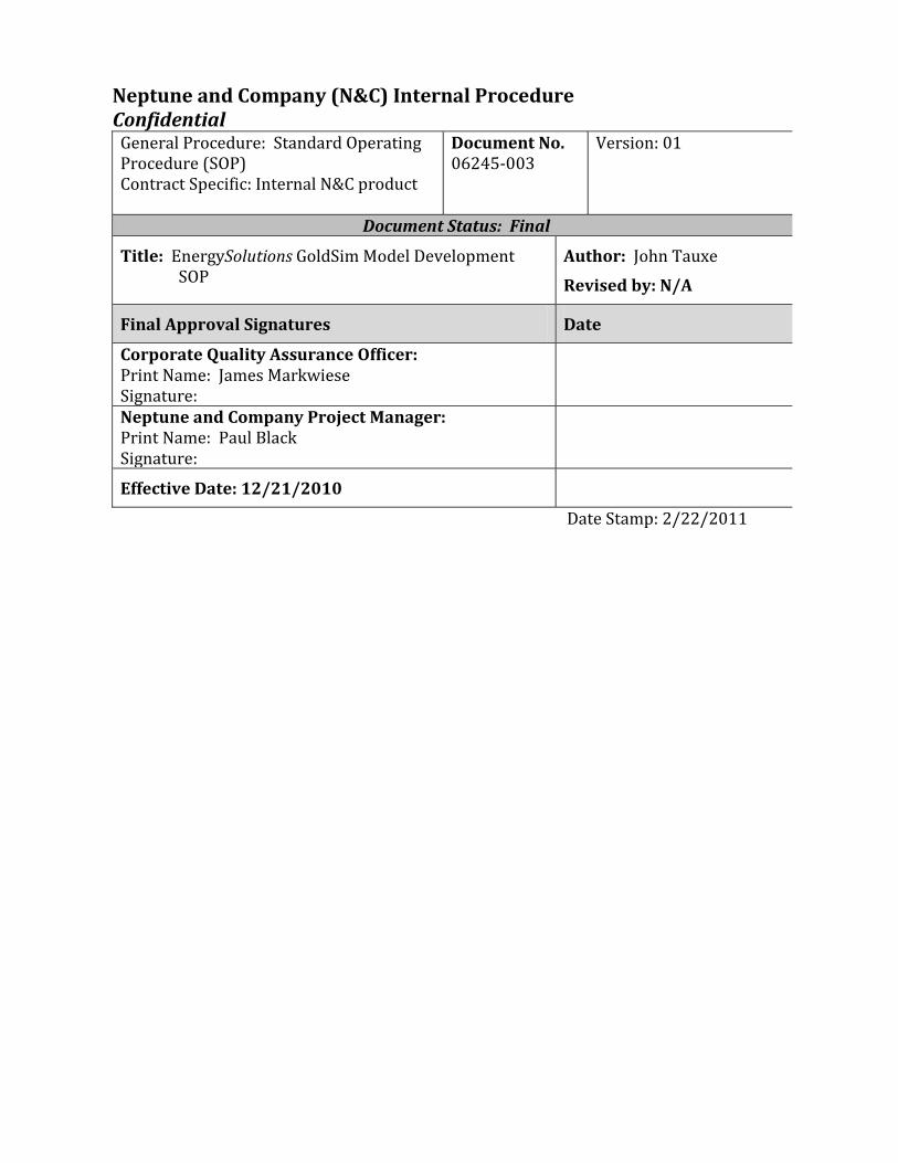
Neptune and Company (N&C) Internal Procedure Confidential
General Procedure: Standard Operating Procedure (SOP) Contract Specific: Internal N&C product
Document No. 06245-003
Version: 01
Document Status: Final
Title: EnergySolutions GoldSim Model Development SOP
Author: John Tauxe
Revised by: N/A
Final Approval Signatures Date
Corporate Quality Assurance Officer: Print Name: James Markwiese Signature:
Neptune and Company Project Manager: Print Name: Paul Black Signature:
Effective Date: 12/21/2010
Date Stamp: 2/22/2011
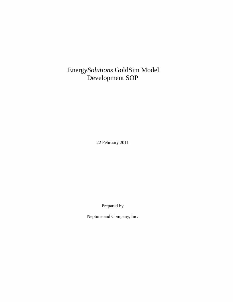
EnergySolutions GoldSim Model Development SOP
22 February 2011
Prepared by
Neptune and Company, Inc.
GoldSim Model Development SOP 22 Feb 2011
GoldSim Model Development SOP ii
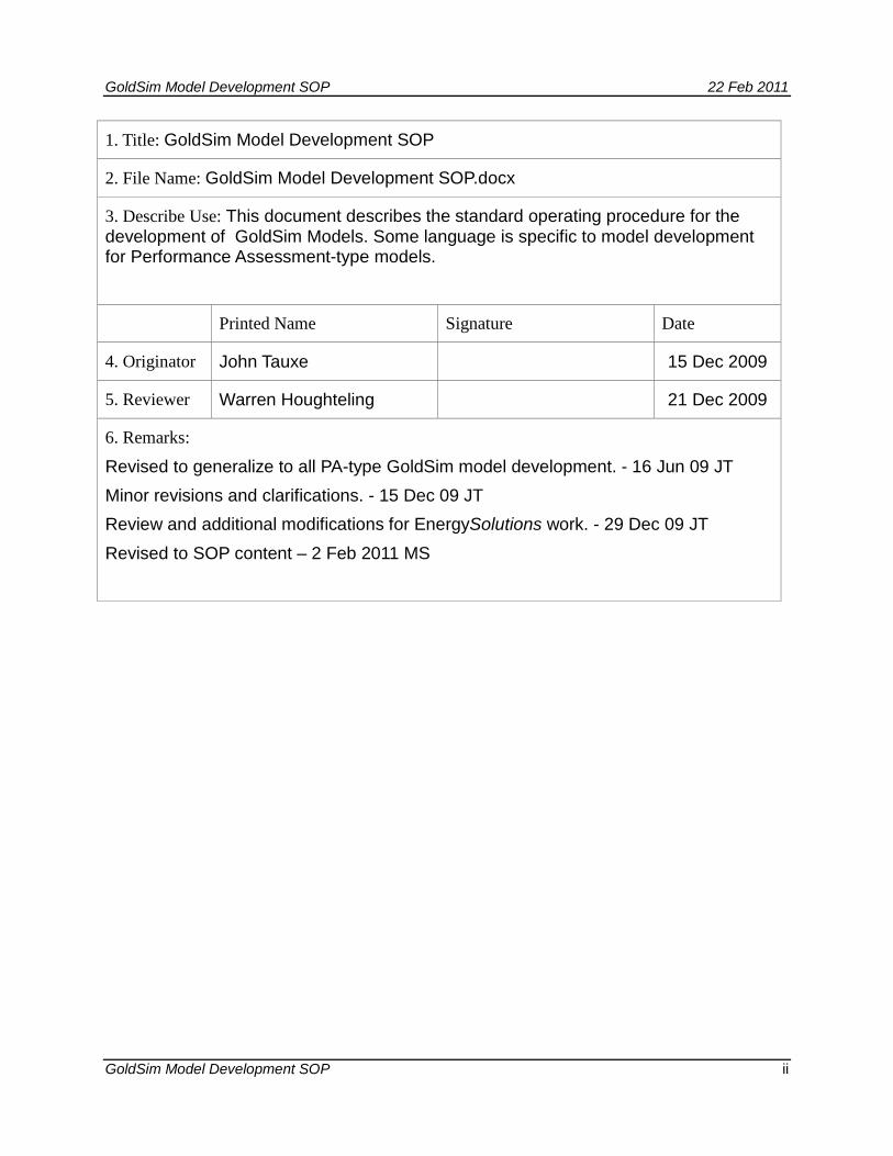
1. Title: GoldSim Model Development SOP
2. File Name: GoldSim Model Development SOP.docx
3. Describe Use: This document describes the standard operating procedure for the development of GoldSim Models. Some language is specific to model development for Performance Assessment-type models.
Printed Name Signature Date
4. Originator John Tauxe 15 Dec 2009
5. Reviewer Warren Houghteling 21 Dec 2009
6. Remarks:
Revised to generalize to all PA-type GoldSim model development. - 16 Jun 09 JT Minor revisions and clarifications. - 15 Dec 09 JT Review and additional modifications for EnergySolutions work. - 29 Dec 09 JT Revised to SOP content – 2 Feb 2011 MS
GoldSim Model Development SOP 22 Feb 2011
GoldSim Model Development SOP iii
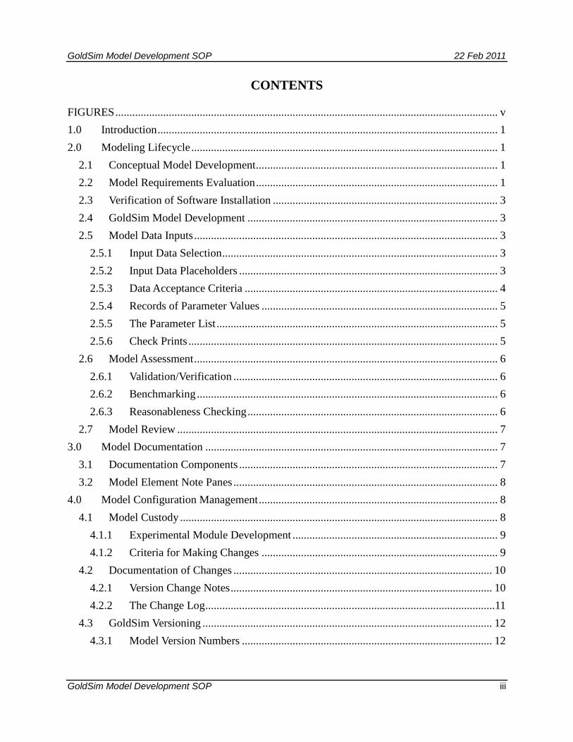
CONTENTS
FIGURES ........................................................................................................................................ v
1.0 Introduction ......................................................................................................................... 1
2.0 Modeling Lifecycle ............................................................................................................. 1
2.1 Conceptual Model Development ...................................................................................... 1
2.2 Model Requirements Evaluation ...................................................................................... 1
2.3 Verification of Software Installation ................................................................................ 3
2.4 GoldSim Model Development ......................................................................................... 3
2.5 Model Data Inputs ............................................................................................................ 3
2.5.1 Input Data Selection .................................................................................................. 3
2.5.2 Input Data Placeholders ............................................................................................ 3
2.5.3 Data Acceptance Criteria .......................................................................................... 4
2.5.4 Records of Parameter Values .................................................................................... 5
2.5.5 The Parameter List .................................................................................................... 5
2.5.6 Check Prints .............................................................................................................. 5
2.6 Model Assessment ............................................................................................................ 6
2.6.1 Validation/Verification .............................................................................................. 6
2.6.2 Benchmarking ........................................................................................................... 6
2.6.3 Reasonableness Checking ......................................................................................... 6
2.7 Model Review .................................................................................................................. 7
3.0 Model Documentation ........................................................................................................ 7
3.1 Documentation Components ............................................................................................ 7
3.2 Model Element Note Panes .............................................................................................. 8
4.0 Model Configuration Management ..................................................................................... 8
4.1 Model Custody ................................................................................................................. 8
4.1.1 Experimental Module Development ......................................................................... 9
4.1.2 Criteria for Making Changes .................................................................................... 9
4.2 Documentation of Changes ............................................................................................ 10
4.2.1 Version Change Notes ............................................................................................. 10
4.2.2 The Change Log .......................................................................................................11
4.3 GoldSim Versioning ....................................................................................................... 12
4.3.1 Model Version Numbers ......................................................................................... 12
GoldSim Model Development SOP 22 Feb 2011
GoldSim Model Development SOP iv
4.3.1.1 Incrementing the version number .................................................................... 14
4.3.1.2 Creating a versioning report ............................................................................ 14
4.4 Model Testing ................................................................................................................. 14
4.5 Model Backup ................................................................................................................ 15
4.6 Error Reporting and Resolution ..................................................................................... 15
4.6.1 Reporting Error Candidates .................................................................................... 15
4.6.2 Assessing Error Candidates .................................................................................... 15
4.6.3 Resolving Errors ..................................................................................................... 16
4.6.4 Error Resolution Verification .................................................................................. 16
4.6.5 Error Impact Assessment ........................................................................................ 16
4.7 Model Distribution ......................................................................................................... 16
5.0 References ......................................................................................................................... 17
GoldSim Model Development SOP 22 Feb 2011
GoldSim Model Development SOP v
FIGURES
Figure 1: Model development work process flow diagram. .............................................................................. 2
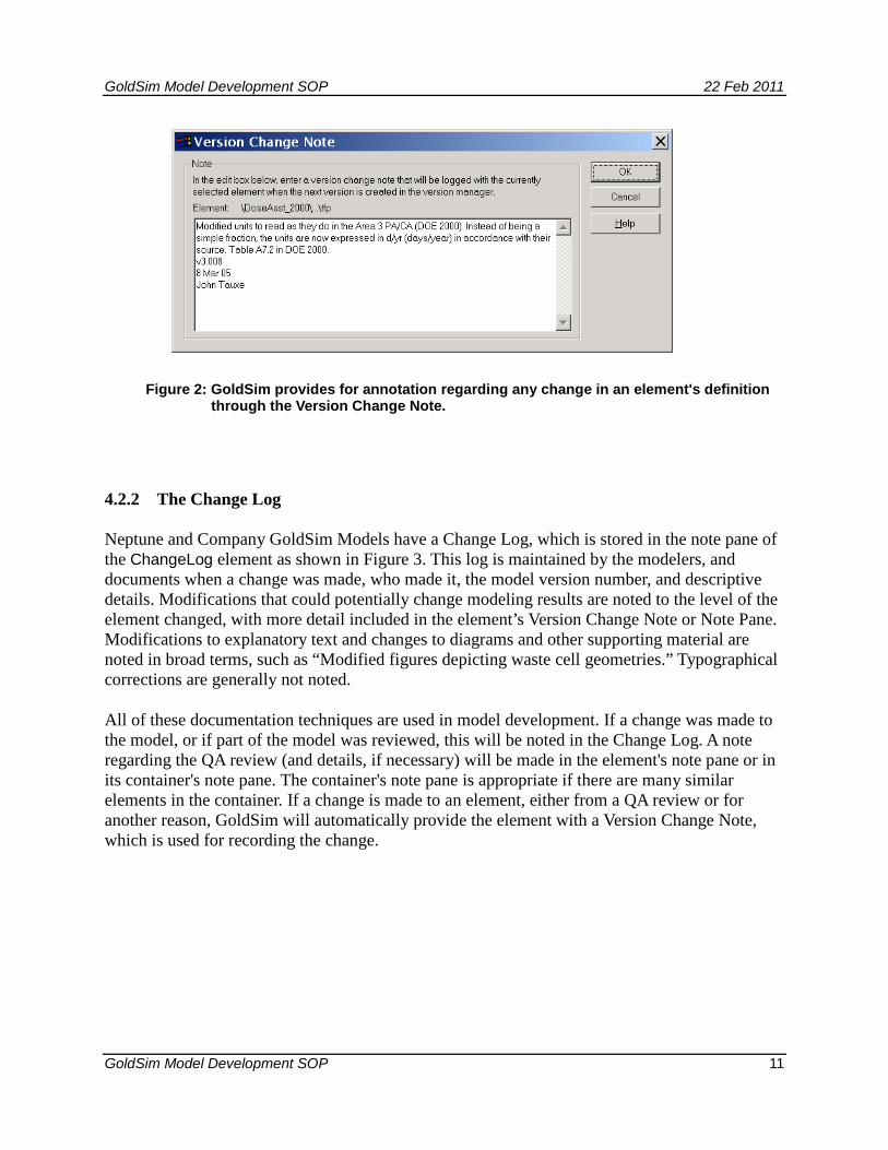
Figure 2: GoldSim provides for annotation regarding any change in an element's definition through the Version Change Note. .......................................................................................................... 11
Figure 3: The model’s Change Log can be maintained using a note pane or a formatted text box. ................ 12
Figure 4: GoldSim has an internal version manager. ....................................................................................... 13
GoldSim Model Development SOP 22 Feb 2011
GoldSim Model Development SOP 1
1.0 Introduction
This standard operating procedure (SOP) describes the development of GoldSim-based computer models. These models are used to perform contaminant transport and dose assessment calculations as the computational basis for radiological Performance Assessments (PA). They are developed using the GoldSim™ systems analysis software, developed by the GoldSim Technology Group (GTG), as a principal platform, commonly in conjunction with various supporting computer programs and data sources. Throughout this document, the term Quality Assurance (QA) refers to a program for the systematic monitoring and evaluation of the various aspects of a GoldSim model development to ensure that standards of quality are being met.
2.0 Modeling Lifecycle
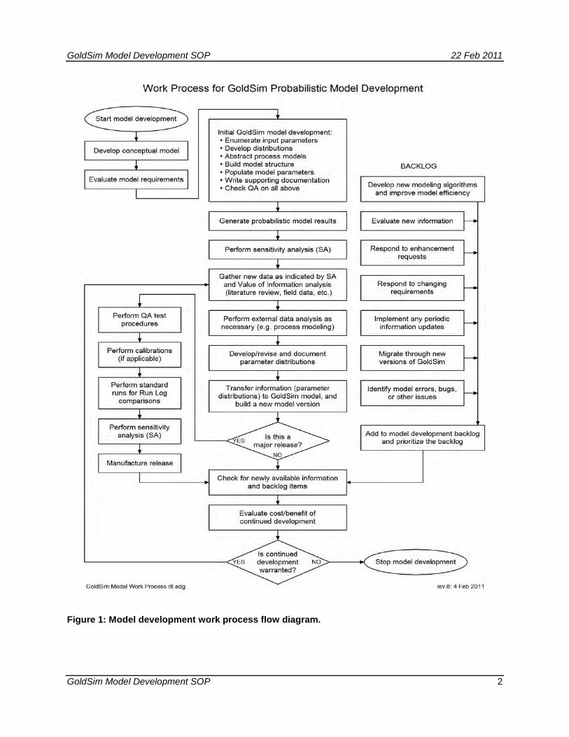
GoldSim model development follows a structured process or lifecycle that requires a graded approach to quality assurance at each phase. The lifecycle for GoldSim model development is described below and correlates with the work process shown in Figure 1.
2.1 Conceptual Model Development
Model development begins with the development of a Conceptual Site Model (CSM). The conceptual site model identifies important features and processes of the system being modeled that are consistent with the existing data. While the process of developing the CSM does not fall under the scope of this SOP, it is mentioned here because it forms the basis for the GoldSim model design.
The CSM is documented in a Conceptual Site Model document, which explains and provides justification for the mathematical approaches for modeling geological, hydrogeological, contaminant fate and transport, and other component process of the overall model. Existing data and literature and expert opinion are used to support the modeling approach described by the CSM.
2.2 Model Requirements Evaluation
The CSM provides a description of the attributes and capabilities of the software required to meet the project objectives. An evaluation is conducted to verify that the GoldSim modeling platform is capable of providing these required attributes and capabilities.
GoldSim Model Development SOP 22 Feb 2011
GoldSim Model Development SOP 2
Figure 1: Model development work process flow diagram.
GoldSim Model Development SOP 22 Feb 2011
GoldSim Model Development SOP 3
2.3 Verification of Software Installation
The GoldSim software is installed and registered as described in the GoldSim User's Guide (GTG 2010a). Following the installation and registration the user runs the example model “FirstModel.gsm” located in the “General Examples” directory and verifies that the output obtained matches the chart shown on page 26 of the User's Guide (GTG 2010a).
The GoldSim User's Guide (GTG 2010a) and the GoldSim Contaminant Transport Module User's Guide (GTG 2020b) provide complete descriptions of the features and capabilities of GoldSim and the Contaminant Transport Module.
2.4 GoldSim Model Development
To begin model development individual modelers work in parallel to model specific sub-processes described in the CSM. For example, existing mathematical models are translated into specific algorithms to be used in the modeling process. GoldSim offers a level of model structure that can closely resemble a conceptual model, so the structural implementation of the GoldSim model will follow the conceptual model developed by the project team. As the different components of the model are developed in GoldSim, they are integrated to form a coherent model of the overall process being studied. GoldSim's object-oriented structure facilitates this process, often allowing independently developed sub-modules to be copied and pasted into the main model. GoldSim's “self-documenting”features allow the graphical user interface (GUI) design to incorporate documentation of modeling concepts and parameter derivation, so that it is relatively easy to crosswalk between individual GoldSim pages and sections of the CSM document.
2.5 Model Data Inputs
2.5.1 Input Data Selection
The development of appropriate definitions of input parameters is guided by model sensitivity analyses, which identify those parameters most important in determining the model results. In some cases, the definition of an input value matters little to the results and in these cases less effort is expended in developing distributions. Sensitive parameters, however, warrant a closer investigation, and their input distributions are devised with great care where possible. All parameters in the model are based on some sort of information source, be it a “literature value”, the result of a site-specific data collection campaign, or the result of expert professional judgment.
2.5.2 Input Data Placeholders
On occasion, a modeling element must be added to the model in order to proceed with construction, but no value has yet been developed. In this case, an ad hoc placeholder value is chosen so that model development may continue, and the parameter is noted as a placeholder.
GoldSim Model Development SOP 22 Feb 2011
GoldSim Model Development SOP 4
Before the model can be relied upon for any purpose, however, all such placeholder values must be replaced with suitably-derived and documented values.
2.5.3 Data Acceptance Criteria
The sources of input data for the model are various, and the quality of the source is a compromise between model sensitivity (identifying the need for high-quality data), availability, appropriateness, and the ability (budget and/or practicality) to generate data of sufficient quality. Input parameters that have a strong influence on the model results as determined by sensitivity analyses are given higher priority than those with little influence.
The choice of data sources depends on the availability and application of the data in the model. The following hierarchy outlines different types of information and their application. The information becomes increasingly site-specific and parameter uncertainty is generally reduced moving down the list.
• Physical limitations on parameter ranges, used for bounding values when no other supporting information is available. Example: Porosity must be between 0 and 1 by definition.
• Generic information from global databases or review literature, used for bounding values and initial estimates in the absence of site-specific information. Example: A common value for porosity of sand is 0.3.
• Local information from regional or national sources, used to refine the above distributions, but with little or no site-specific information. Example: Sandy deposits in the region have been reported to have porosities in the range of 0.30 to 0.37, based on drilling reports.
• Information elicited from experts regarding site-specific phenomena that cannot be measured. Example: The likelihood of farming occurring on the site some time within the next 1000 years is estimated at 50% to 90%.
• Site-specific information gathered for other purposes. Example: Water well drillers report the thickness of the regional aquifer to be 10 to 12 meters.
• Site-specific modeling and studies performed for site-specific purposes. Example: The infiltration of water through the planned engineered cap is estimated by process modeling to be between 14 and 22 cm/yr.
• Site-specific data gathered for specific purposes in the models. Example: The density of Pogonomyrmex ant nests adjacent to the site is counted, and found to be 243 nests per hectare.
GoldSim Model Development SOP 22 Feb 2011
GoldSim Model Development SOP 5
The determination of data adequacy is informed by a sensitivity analysis of the model, which identifies those parameters most significant to a given model result. Such parameters are candidates for additional measurements or more deliberate estimation. As the model development cycle proceeds, sensitive parameters are identified and their sources are evaluated to determine the cost/benefit of reducing their uncertainty.
2.5.4 Records of Parameter Values
One limitation of the GoldSim platform is that there is no straightforward way to examine all the values of inputs (data and stochastic elements) in one place. The user must search the model and open (or “mouse-over”) each input element individually in order to see its value. In order to overcome this inconvenience, all the parameter inputs are stored external to the model, in the Parameter List documents.
2.5.5 The Parameter List
The Parameter List is a complete list of the input parameters for the model, and may consist of a text document, a workbook of spreadsheets, a database, or a combination of these, depending on the changing capabilities of the GoldSim modeling platform. Each parameter is listed in only one place, so that there is no ambiguity about the proper value of a parameter. Accompanying the listing of the parameter value in the Parameter List is a reference to its origin, which may be in a white paper or literature reference. Any change to a parameter is made to the Parameter List first, and then the change is made to the model. The value in the Parameter List is cross-checked to its source via a check print (see below), and the value in the model is then changed, noted in the Version Change Note for the modified element, and in the Change Log.
2.5.6 Check Prints
Whenever information (e.g. a parameter distribution) is transferred from one record to another (e.g. from a site document to the Parameter List) a QA Check Print process is invoked. This process is intended to positively and unambiguously document the source of information for each model input parameter or distribution. Since GoldSim is not capable of printing out a list of all the parameters that exist in the model, a separate document—the Parameter List—is maintained in exact concordance with the model at all times.
The flow of information is from primary sources (field data, literature, expert elicitations, etc.) to white papers that develop the input distributions (this step may not apply to all cases), to the Parameter List to the GoldSim model. QA check prints are maintained in all but the final step—transferring input values to the model. The check print process consists of obtaining paper copies of the data source and its destination, such as a paper from the literature and the Parameter List, for example. A comment field in the Parameter List (either a column in a table, a comment attached to a spreadsheet cell, or other location unambiguously associated with the data) identifies the value’s origin. A paper copy of that page or pages of the Parameter List is stapled to a paper copy of the data source (which may be simply the page from the identified source), and the QA reviewer annotates each page. Typically, a yellow highlighter is used to indicate each
GoldSim Model Development SOP 22 Feb 2011
GoldSim Model Development SOP 6
positively-checked value, and a red pen identifies any value that does not match. After checking each value against its source, the check print is documented with the date and the signature of the checker. Errors discovered in the process are noted, the errors are corrected in the destination document, and the values are rechecked with a subsequent check print, which is stapled to the original. This process is repeated until the check prints can document that information transfers are error-free. Check prints are stored as hard copy at N&C.
The final step of information transfer—from the Parameter Document to the GoldSim model—does not lend itself to check printing. However, traceability of parameter information can be maintained using GoldSim's internal QA tools, such as Note Panes and Version Change Notes discussed in Sections 3.0 and 4.0.
2.6 Model Assessment
Assessment of the proper operation of the Model is done on two levels. The overall model, as represented in the results, is subjected to benchmarking with process model results if a process model is available, and is compared to previous versions of the Model to assure that incremental changes are in line with those expected from modifications to the Model. On a submodel scale, particular parts of the Model may be assessed independently.
2.6.1 Validation/Verification
Many computer models that attempt to predict the outcomes of processes and events can be validated (verified) with measurable results. Due to the nature of performance assessments, which attempt to estimate concentrations and fluxes of materials in environmental media and the possible doses resulting from those materials far into the future, the results are not amenable to this validation. It is not possible to “test” the model to see if it has done a good job of predicting the dose to a hypothetical individual 10,000 years from now. The methods listed below, however, are used to demonstrate that reasonable efforts have been taken to ensure that the models are valid.
2.6.2 Benchmarking
Benchmarking consists of reproducing the deterministic results of the process model calculations using an established process model and GoldSim. This “benchmarking” is a fundamental high-level corroboration of the model implementation and calculations. Agreement between the two models serves to build confidence in the validity of the GoldSim model.
2.6.3 Reasonableness Checking
A model can incorporate several tools for checking the reasonableness of certain inputs and results. Examples follow:
• Intermediate results are provided where they are useful for checking calculations.
GoldSim Model Development SOP 22 Feb 2011
GoldSim Model Development SOP 7
• Mass balance checks demonstrate that the mass of materials (soil, water, air) and radionuclides is preserved. This is a fundamental requirement of physical environmental models.
• To check the reasonableness of the results of a particular algorithm, the modeler may set up equation(s) both as an element in GoldSim and also using another tool, for example a Microsoft Excel Spreadsheet. This allows the modeler to compare results using two different calculation methods to provide a higher level of confidence that the algorithm has been implemented correctly in the GoldSim environment.
2.7 Model Review
Model development is subject to review by a modeler different from the one who did the original model building. As parts of the model are revised, with changes in parameters, expressions, or other functional elements, or model structure, these changes are reviewed for accuracy and completeness. Any accompanying text on the model pages is also reviewed for clarity and accuracy. The modeler making the changes identifies which parts of the model are subject to review, and another N&C GoldSim modeler examines these in detail, providing review comments to the originating modeler. The entire model is subjected to review before release to the client (see Section 4.7).
3.0 Model Documentation
3.1 Documentation Components
The Model is documented both internally and externally. Internal documentation includes the Change Log, Version Change Notes, modeling element Note Panes, and GoldSim's versioning capability. External documentation includes white papers, check prints, and a Parameter List. White papers document the development of specific algorithms and other inputs to the GoldSim model and are intended to explain and justify the approach taken.
A typical page in the model consists of model elements and explanatory text. Each page represents a modeling concept, and the model is logically divided into parts that will fit onto pages. Text at the top of each page explains the function of the page, and text juxtaposed with the model elements explains the function of the element, and provides information about its source. Each element also has a description field that is used for a short descriptive identifier.
The influence of one model element on another can be easily traced through the model using the “Show All Links” function attached to the triangle-shaped arrows on each side of the element graphic. The left triangle, pointing into the element, shows the other elements referenced by the current one, and the right triangle, pointing out of the element, shows the other elements that are dependent on it. By following these links, the complete interdependency of elements can be
GoldSim Model Development SOP 22 Feb 2011
GoldSim Model Development SOP 8
traced through the model. In addition to descriptive text on the page, illustrations made with native drawing tools can be added to better communicate modeling concepts.
3.2 Model Element Note Panes
Associated with each GoldSim modeling element is the optional Note Pane feature. If an element has a note, it is identified by an underlined element name. Note panes have a dual purpose in the model. They are used for general information, describing the purpose of a container or element. They also serve the QA process, as a convenient place to make notes about the source of information or the status of QA review. While most of the note pane is free-format, the QA-related notes are to include a date (which can be cross-indexed to a version number using the Change Log, described below), the name of the person making the note, and a description about the nature of the QA check. For example, a QA note for an entire container might read:
1 Apr 05 JT QA for this container completed 13 Apr 05 JT QA updated with cross-check of water tortuosity exponent
parameter values and one for an individual element:
13 Aug 04 JT Verified source of these data: Each value was checked against the 15th edition of the Chart of the Nuclides (General Electric Co. and Knolls Atomic Power Laboratory, 1996), wall chart version.
28 Sep 04 JT Updated and verified source of these data: Each value was checked against the 16th edition of the Chart of the Nuclides (General Electric Co. and Knolls Atomic Power Laboratory, 1996), booklet version.
If an element is actually changed in the process of a QA review (or for any other reason), such change is noted in the Version Change Note associated with that element.
4.0 Model Configuration Management
Managing the model configuration through its various versions is critical to the production of a usable modeling product that meets client requirements. The following sections discuss various topics relevant to model modification and control.
4.1 Model Custody
During model development, the baseline model is tracked by the lead modeler. In the event that another modeler needs to have custody of the model for development purposes, the custody will be passed to that modeler and returned when the work is finished. The current custodian is always known, and is recorded on the topmost page of the model (except in released versions).
GoldSim Model Development SOP 22 Feb 2011
GoldSim Model Development SOP 9
Modelers make use of the internal GoldSim versioning and Change Log in order to document changes made to the model.
A GoldSim model differs from many other software development projects in that it exists in a single binary file (with the “.gsm” extension). There are no separate files for subroutines as in a more low-level programming language like C, FORTRAN, or even Java. Therefore, the model cannot be edited by more than a single person at a time. At any given time, there is a single “main” model file. The custody of the main model must be explicitly passed from the lead modeler to another, and the custody is always known by the lead modeler, who is also the default custodian. The lead modeler may assign custody to another for a particular modeling task, but will resume custody when that task is completed. Upon return of custody, the returned model is inspected and one of two paths is chosen: 1) The returned model is maintained as the baseline model, or 2) the baseline model is modified appropriately to incorporate changes made in the returned model, and the modified baseline model is retained as the new baseline model. The baseline model resides on the custodian’s computer, and is backed up by several methods; including off-site media (see Section 4.5).
4.1.1 Experimental Module Development
On occasion, model development requires some experimentation that may not be desirable in the main model. In such cases, a copy of the main model is made and given a unique file name in order to keep it distinct from the main model. This “branch copy” is used for module development and prototyping of modeling methods. Once the prototype of a specific module is complete, tested, and accepted, the new model parts are re-integrated into the main model, either by copying model containers and elements from the branch copy into the main model (the preferred method), or by re-entering elements directly into the main model in cases where GoldSim will not allow copying between model files. Either way, the additions and/or changes to the main model are cross checked for accuracy (by a modeler other than the one implementing the change), and the modifications are noted in the Change Log (see Section 4.2.211). At all times, however, there is only one main model file.
4.1.2 Criteria for Making Changes
Changes to the model occur at different levels. Minor changes to internal documentation language, including clarifications of text and correction of typographical errors, are made as they are identified, and without formal documentation. Changes involving any type of data input or calculation that could potentially affect the modeling results are documented in the Change Log.
A change to an input parameter (e.g. a distribution) may be precipitated by the following:
• QA review, in which model parameters are found to not match their values as documented outside the model. In such a case, the value in the model would be determined to be in error.
GoldSim Model Development SOP 22 Feb 2011
GoldSim Model Development SOP 10
• A decision by a subject matter expert (SME), generally in consultation with other project team members, that a value should be changed for some technical reason, such as the availability of new data on which a distribution is based. This would be considered an update, and the change would cascade through the proper sequence, from an update to the data set, through development of an updated distribution, updating of the documentation in a white paper (if applicable) and in the Parameter List and finally an update to the model itself, with an accompanying entry in the Change Log and in the parameter element’s Version Change Note (see Section 4.2.1. Each step in the change sequence is reviewed by an individual other than the person implementing the change.
• Major changes to the model, such as changing the species list, adding a contaminant transport process, a waste configuration, or an exposure scenario, are discussed and planned by Team SMEs.
4.2 Documentation of Changes
The documentation of changes made to the model is done at a level appropriate to the changes. If individual parameters are modified or added, this is documented with a note provided in the model element’s Version Change Note, referencing the nature of the change, who made it, and date of the change. The name of the changed element is noted in the Change Log, along with the model version number, date of the change, the name of the person executing the change, and the name of the reviewer of the change process. Such changes may also be noted in the element's Note Pane or that of its container.
4.2.1 Version Change Notes
Version Change Notes (Figure 2) are automatically attached by GoldSim to any model element that has been modified, and are used to store information about changes in any particular element. GoldSim keeps a versioning database within the Model, consisting of a list of all changes to the model between version-stamps, and the text supplied in the Version Change Notes. At any time, GoldSim can generate a report of changes made between versions. Once a model version number has been incremented, all Version Change Notes are “reset” and a new set begins for that version. Any information that is to be maintained through versions for viewing by users or reviewers, such as QA reviews, is kept in the Note Panes associated with model elements or containers. Any time an element is edited, a log entry is generated internally by GoldSim documenting the event. Note that this happens even if nothing is actually changed in the element when the “OK” button is chosen in the dialog. Use of the “Cancel” button does not signal a change.
GoldSim Model Development SOP 22 Feb 2011
GoldSim Model Development SOP 11
Figure 2: GoldSim provides for annotation regarding any change in an element's definition through the Version Change Note.
4.2.2 The Change Log
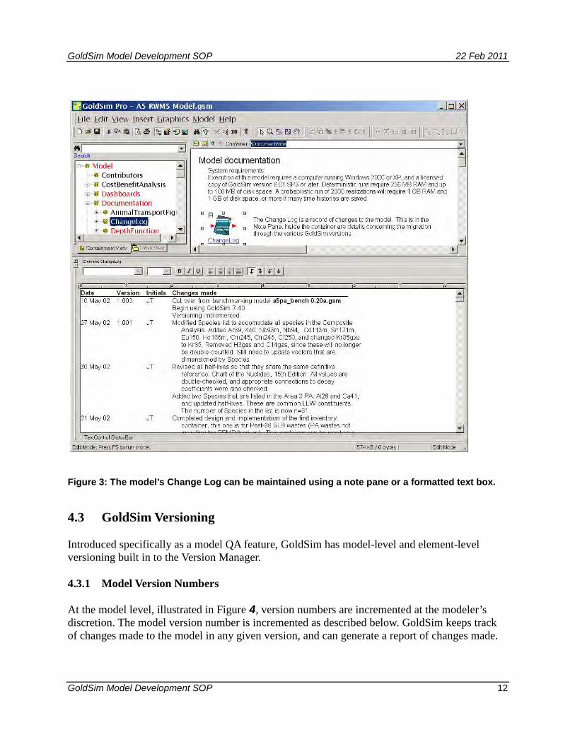
Neptune and Company GoldSim Models have a Change Log, which is stored in the note pane of the ChangeLog element as shown in Figure 3. This log is maintained by the modelers, and documents when a change was made, who made it, the model version number, and descriptive details. Modifications that could potentially change modeling results are noted to the level of the element changed, with more detail included in the element’s Version Change Note or Note Pane. Modifications to explanatory text and changes to diagrams and other supporting material are noted in broad terms, such as “Modified figures depicting waste cell geometries.” Typographical corrections are generally not noted.
All of these documentation techniques are used in model development. If a change was made to the model, or if part of the model was reviewed, this will be noted in the Change Log. A note regarding the QA review (and details, if necessary) will be made in the element's note pane or in its container's note pane. The container's note pane is appropriate if there are many similar elements in the container. If a change is made to an element, either from a QA review or for another reason, GoldSim will automatically provide the element with a Version Change Note, which is used for recording the change.
GoldSim Model Development SOP 22 Feb 2011
GoldSim Model Development SOP 12
Figure 3: The model’s Change Log can be maintained using a note pane or a formatted text box.
4.3 GoldSim Versioning
Introduced specifically as a model QA feature, GoldSim has model-level and element-level versioning built in to the Version Manager.
4.3.1 Model Version Numbers
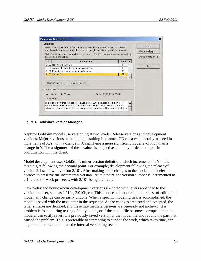
At the model level, illustrated in Figure 4, version numbers are incremented at the modeler’s discretion. The model version number is incremented as described below. GoldSim keeps track of changes made to the model in any given version, and can generate a report of changes made.
GoldSim Model Development SOP 22 Feb 2011
GoldSim Model Development SOP 13
Figure 4: GoldSim's Version Manager.
Neptune GoldSim models use versioning at two levels: Release versions and development versions. Major revisions to the model, resulting in planned CD releases, generally proceed in increments of X.Y, with a change in X signifying a more significant model evolution than a change in Y. The assignment of these values is subjective, and may be decided upon in coordination with the client.
Model development uses GoldSim’s minor version definition, which increments the Y in the three digits following the decimal point. For example, development following the release of version 2.1 starts with version 2.101. After making some changes to the model, a modeler decides to preserve the incremental version. At this point, the version number is incremented to 2.102 and the work proceeds, with 2.101 being archived.
Day-to-day and hour-to-hour development versions are noted with letters appended to the version number, such as 2.010a, 2.010b, etc. This is done so that during the process of editing the model, any change can be easily undone. When a specific modeling task is accomplished, the model is saved with the next letter in the sequence. As the changes are tested and accepted, the letter suffixes are dropped, and these intermediate versions are generally not archived. If a problem is found during testing of daily builds, or if the model file becomes corrupted, then the modeler can easily revert to a previously saved version of the model file and rebuild the part that caused the problem. This is preferable to attempting to “undo” the work, which takes time, can be prone to error, and clutters the internal versioning record.
GoldSim Model Development SOP 22 Feb 2011
GoldSim Model Development SOP 14
4.3.1.1 Incrementing the version number
The following insert illustrates the documentation of incrementing development versions, as recorded in the Change Log:
1) Make a final entry in the Change Log under version 1.034 that you are incrementing the version number (see Figure 3): 29 Jun 02 1.034 JJ Versioning counter updated to 1.034, and model saved.
2) Immediately change the internal versioning to 1.034 using “Model | Versioning...” (see Figure 4)
3) Save the model as "name v1.034.gsm", (any name plus the version number) overwriting all previous versions of that name.
4) Change the file attributes to “read only” so that the model file will not be inadvertently overwritten.
5) Change the front page and the Change Log entries to 1.035. 29 Jun 02 1.035 JJ Begin work on v1.035.
6) Save the model as "name v1.035a.gsm" (or similar)
7) Begin work on version 1.035, starting at intermediate development version 1.035a.
8) After developing using intermediates 1.035a, 1.035b, 1.035c, etc., determine when to save the model as 1.035, and return to step 1) using the new version number.
4.3.1.2 Creating a versioning report
A report can be generated from GoldSim (using the “Generate Report...” button shown in Figure 4), listing all changes to the model for a particular version. The report is a text file with global changes as well as changes to individual elements, including the text from the Version Change Notes.
4.4 Model Testing
Any time a change is made to the model calculations that could change the results; the effects of the change are assessed. Model testing is relatively easy using GoldSim, since the results of any element in the model can be examined through a time series or final value. This enables straightforward parallel calculations to be done in order to verify correct and consistent operation. The modeling environment also allows the simple creation of temporary elements to perform calculations parallel to any others in the model.
Model testing is most readily done on discrete parts of the model, where results of a small number of straightforward calculations can be examined. Confirmation of discrete parts of the model are done by constructing a test model in GoldSim that is focused in its analysis. Ideally, this test model is excised directly from the main model, so that all relationships and definitions
GoldSim Model Development SOP 22 Feb 2011
GoldSim Model Development SOP 15
are preserved. For example, to verify that GoldSim is performing diffusion calculations as expected, a simple GoldSim model can be constructed to examine the diffusion of materials between various media in two cells, and the results can be compared to an analytical solution to the diffusion equation. Calculations verified in the test model give confidence in the correct operation in the model.
4.5 Model Backup
Preservation of electronic model files is paramount in any software development project. Several redundant methods are employed for backup of the GoldSim model files and all other files and documentation. Foremost are project files maintained on an N&C server, which are backed up daily on a separate hard drive. Incremental versions of the model are likewise backed up locally and in addition to this, the lead modeler keeps a copy on his/her computer, and backs that copy up to a N&C server. Off-site backups are also maintained.
4.6 Error Reporting and Resolution
As errors are discovered, they must be identified, reported, and resolved. This section discusses the handling of errors in the development of a model. Formal tracking of errors, bugs, and other issues will be done using an issue-tracking system maintained by the QA manager and lead modeler.
4.6.1 Reporting Error Candidates
Errors such as typographical errors in supporting text are not considered in this process. Errors considered for this process include errors in parameter data entry or GoldSim programming. If an error is suspected, it is to be reported to the lead modeler along with any supporting information. It is the responsibility of the lead modeler to evaluate the error candidate and see that the issue is resolved.
Data entry errors may be discovered in input elements (Data or Stochastic GoldSim model elements). These are also brought to the attention of the lead modeler. These or any other modeling issues are to be entered into the issue-tracking system.
4.6.2 Assessing Error Candidates
Once an error candidate has been brought to the attention of the lead modeler via the issue-tracking system an assessment must be made to determine if the candidate is in fact an error. This is usually a simple process, involving examining a mathematical expression or a piece of entered data. Real errors are subject to resolution. False errors are commonly dismissed, noting the resolution in the issue-tracking system. If, however, the problem was due to some other cause, such as an ambiguity in documentation, the causes of the identification of a false error may require attention.
GoldSim Model Development SOP 22 Feb 2011
GoldSim Model Development SOP 16
4.6.3 Resolving Errors
Errors, once discovered and confirmed, are usually easily remedied. Like other changes to the model, fixing an error is documented at least in Version Change Notes and the Change Log. Resolution is also noted in the issue-tracking system.
4.6.4 Error Resolution Verification
Checking the error resolution may be as simple as cross-checking an input value with the value in the Parameters List to ensure it is correct. Alternatively, a modification to an expression may involve an independent check of the calculation, using a spreadsheet, calculator, or a separate GoldSim model.
4.6.5 Error Impact Assessment
Each resolved error is assessed regarding its potential effect on the results. If the effect is anything more than negligible, its discovery and resolution are reported to the project participants via email. Similarly, if the error could have had an effect on the results of previous versions of the model, this is also reported.
4.7 Model Distribution
GoldSim models, like other computer model software, are open to modification. This is a benefit for modelers and researchers, since the logic is transparent and the model is easily maintained. This is a potential detriment to model integrity for the same reason. There are ways to tell if a model has been tampered with, however, as discussed above. Versioning, and the tracking of all changes between versions is important. Nevertheless, developers and clients alike need to know the configuration status of the model they are using, and the read-only media-released versions always provide unambiguous starting points.
Release versions of the model(s) are delivered to the client on read-only media (such as a CD-ROM), which inherently precludes modification of the models and supporting files. Using this method of delivery ensures that there is no ambiguity about the model and supporting documentation that constitutes the deliverable.
The standard GoldSim software allows for complete construction and editing of models. The companion GoldSim Player, however, is currently available at no cost and can run GoldSim models that have been specifically “exported” as Player versions. The Player version of the model is not editable. For distribution to the general public, a GoldSim Player version of a Model can be provided as part of the deliverable. The Player model cannot be modified in its significant parts, though the user can still operate switches and controls to evaluate various effects.
GoldSim Model Development SOP 22 Feb 2011
GoldSim Model Development SOP 17
5.0 References
GTG (GoldSim Technology Group), 2010a, GoldSim User's Guide: Volumes 1 and 2, GoldSim Technology Group LLC, Issaquah, WA.
GTG (GoldSim Technology Group), 2010b, GoldSim Contaminant Transport Module User's Guide, GoldSim Technology Group LLC, Issaquah, WA.

Appendix C - EnergySolutions Issue Tracker Standard Operating Procedure
Neptune and Company (N&C) Internal Procedure Confidential
General Procedure: Standard Operating Procedure (SOP) Contract Specific: Internal N&C product
Document No. 06245-004
Version: 01
Document Status: Final
Title: EnergySolutions Issue Tracker SOP Author: Warren Houghteling
Revised by: N/A
Final Approval Signatures Date
Corporate Quality Assurance Officer: Print Name: James Markwiese Signature:
Neptune and Company Project Manager: Print Name: Paul Black Signature:
Effective Date: 12/21/2010
Date Stamp: 2/22/2011
2
Energy Solutions Issue Tracker for the Clive Performance Assessment Model Standard Operating Procedure
Introduction For the Energy Solutions Clive Facility Performance Assessment, Neptune and Company has set up an issue tracking system for the performance assessment model and associated documentation. An issue tracking system contributes to product quality in two major ways:
1. It assures that issues, once discovered, are not overlooked or “lost in the shuffle” by providing a centralized location for all issue reports.
2. It provides documentation of how the issue was identified, the steps taken to correct it, and the steps taken to verify that issue was in the end resolved in a satisfactory manner.
Without a formal issue tracking system, this kind of information is often contained in emails or other more transient forms of communications (e.g., instant messaging), making it difficult to reconstruct the process that was followed in identifying and resolving an issue. An issue tracking system provides a high level of transparency to the issue discovery and resolution process, lending a much higher level of confidence to the quality of the product being tracked.
The “ES Issue Tracker” is based on the open-source Bugzilla software defect tracking system (http://www.bugzilla .org). As stated on the Bugzilla web site,
Bugzilla is a "Defect Tracking System" or "Bug-Tracking System." Defect Tracking Systems allow individual or groups of developers to keep track of outstanding bugs in their product effectively. Most commercial defect-tracking software vendors charge enormous licensing fees. Despite being "free", Bugzilla has many features its expensive counterparts lack. Consequently, Bugzilla has quickly become a favorite of thousands of organizations across the globe.
Bugzilla is a web-based application, which makes is easy to access by anyone with a web browser. The Neptune “ES Issue Tracker” uses version 3.4.6 of the Bugzilla software and is hosted at http://zeus.neptuneinc.org/es-issuetracker/. Bugzilla can be configured for use with one of a number of different database management systems (DBMS) for its database back end. The ES Issue Tracker uses the PostgreSQL open-source database management system (http://www.postgresql.org). The current installation uses PostgreSQL version 8.3.9. The issues database is backed up nightly by an automated script that runs on the database server machine. Creating a User Account To use the issue tracker, one must first create a user account. The site’s main page features a large “Open a New Account” button as well as having “New Account” links that appear on
3
both the top and bottom toolbars found on each page of the site. Once a user has created an account and logged in, these links are replaced by “Log out” links. Clicking on the button or on one of the links brings up a screen where the user is prompted to enter a valid email address. All Bugzilla usernames are email addresses – this makes it easy for Bugzilla to keep users informed of the status of the issues it tracks via email. Once the user has entered an email address, they will receive an email confirming that their account has been created. The email will provide a temporary password and instructions for logging on to the site and setting up a permanent password and other aspects of their user profile. Bugzilla is designed to allow anyone who can access the site to create a user account. However, the software can be configured with security permissions that strictly control which users can access the different aspects of the site’s functionality. In other words, despite its open architecture, Bugzilla is also able to tightly control “who sees what” in terms of the information stored in the Bugzilla database.
Filing an Issue When a problem is discovered with the performance assessment model or documentation, anyone on the team may file an issue report. The home page features a large “File an Issue” button, plus “new” links in the top and bottom toolbars. Upon clicking one of these, the user will be directed to one of two pages. If they have not yet logged in, they will be prompted to do so, and upon successful login they will be redirected to the Issue entry form, or they will go straight to the entry form if already logged in. At the top of the entry page are the following instructions: “Before reporting an issue, please read the issue writing guidelines, please look at the list of most frequently reported issues, and please search for the issue.” For the ES Issue Tracker, Neptune has customized the issue reporting guidelines that come with Bugzilla to make them specific to performance assessment model development. All users of the system MUST read this document, as it specifies requirements for filling out an effective issue report, including required fields (these are also covered in the following section). The other two links are designed to help the user avoid entering duplicate information into the system, given that more than one person may come across the same issue at more or less the same time.
Required Form Parameters
Product / Component Bugzilla supports tracking issues with multiple different products in a single installation. Each product has at least one “component,” a distinct functional unit against which issues are tracked. The ES Issue Tracker is dedicated to a single product, the “Clive PA Model,” so it is only necessary to choose a component.
4
Version The user must select a version of the product against which to report the issue. If there is a newer version of the model available, the user must try to reproduce the issue with the latest version, in case it has already been addressed. The procedure for assigning versions to GoldSim models is described in section 4.3 of the Neptune document “GoldSim Model Development SOP.”
Summary The summary field describes the issue in approximately 60 or fewer characters. A good summary should quickly and uniquely identify an issue report. It should explain the problem, not a suggested solution.
Description This section provides the details of the problem report, including:
• Overview: More detailed restatement of summary. o e.g. “Crash occurs on realization 138 when 1,000 realizations are selected.”
• Steps to Reproduce: Minimized, easy-to-follow steps that will trigger the issue. Include any special setup steps.
o e.g. “Run v1.103 in probabilistic mode, with 1,000 realizations and the seed set to 1.”
• Actual Results: What the application did after performing the above steps. e.g. “GoldSim crashes, without even an error dialog.”
• Expected Results: What the application should have done were the issue not present.
o e.g. “Expected simulation to continue.” • GoldSim Version: GoldSim version in which issue first encountered.
o e.g. “GoldSim v10.02” • Additional Versions: Whether the issue exists in other model or GoldSim versions.
o e.g. “Also occurs using GoldSim 10.11, but cannot test older versions.” • Additional Information: Any other useful information.
For crashing issues: • Any information provided in an error message.
Optional Parameters These parameters are preset with default values and do not necessarily need to be adjusted by the person filing the new issue.
Severity This parameter indicates the severity of the issue. Values range from “enhancement” (essentially a new feature request rather than a defect) to “blocker” (an issue so severe that it is preventing development from moving forward). Defaults to “normal” and can be adjusted throughout the lifecycle of the issue.
5
Hardware This value is hard-coded to “PC” as this is the only hardware that GoldSim currently supports.
OS Operating system – currently hard-coded to ‘Windows.”
Advanced Fields At the top of the issue entry form is a link titled “Show Advanced Fields.” By clicking on this link the user can adjust some fields that have already received default values based on the values of the standard fields.
Priority This field represents the priority that will be assigned to the issue. Priorities are used to determine the order in which issues will be addressed. Priority may correlate with severity, but do not necessarily need to do so. The default priority is P5, the lowest. Priorities will be managed (usually by the technical lead in conjunction with the project manager) during the issue triage process described during succeeding sections of this document.
Initial State This defaults to “NEW,” but could be set to “ASSIGNED” if the issue is being reported by the technical lead and they are ready to assign the issue to a team member. The meanings of the different issue states will be discussed in the following section.
Assign To Each component is given a default assignee when it is created. For the ES Issue Tracker, all issues are initially assigned to the technical lead to be reviewed and assigned to the appropriate team member. However, if the technical lead is reporting the issue, he might choose to assign it directly to a team member.
CC The CC list for an issue defines a list of users who will be cc’d on all emails generated by the issue. Anyone who wants to be kept abreast of developments on the issue can be added to the list. When a component is created, it can be assigned a default CC list. For the ES Issue Tracker, the default CC list for each component includes the project manager and the technical lead.
URL This Bugzilla field is not used in the ES Issue Tracker implementation and can be ignored.
Depends on This field can be used to indicate that the resolution of an issue depends on the resolution of one or more existing issues. Input to the field should be a comma-separated list of existing issue numbers. Bugzilla can use this information to create dependency trees that
6
illustrate the relationship(s) between issues. Bugzilla will also prevent issues that are marked as depending on other issues from being changed to status RESOLVED until the all its blocking issues are first marked as resolved.
Blocks This field can be used to indicate that resolution of this issue blocks the resolution of one or more existing issues. In other words, the other issues cannot be effectively resolved unless this issue has been resolved first. Input to the field should be a comma-separated list of existing issue numbers. Bugzilla can use this information to create dependency trees that illustrate the relationship(s) between issues. As noted above, Bugzilla also requires that issues blocking a given issue be resolved before the blocked issue may be marked as resolved.
Committing the Issue Report When all required fields (and possibly some or all of the optional fields) have had values entered, the user clicks on the “Commit” button to add the issue report to the database. If any required fields have not been set, the user will receive an error message and be asked to hit the “back” button in their browser and fill in the missing information. Once the issue is created, Bugzilla will send email to the issue assignee (unless the assignee is the same user as the issue reporter) and anyone on the CC list for the issue, notifying them of the creation of the issue and providing brief summary information and a URL link to the full issue report. The reporter of the issue will not receive an email. Bugzilla’s default behavior is to assume that a user who creates or updates an issue report knows that they have done so and does not need an email notification. However, once the issue begins to progress through its life cycle (described in the following section), the reporter will receive email notifications whenever anyone else adds information to or changes the status of the issue report.
Issue Life Cycle Once it has been created, an issue report has a life cycle in which it moves from one status state to the next until it reaches the “CLOSED” status, which indicates that the issue has been resolved and the resolution verified. The management of this life cycle is the core of how Bugzilla contributes to product quality by ensuring a rigorous QA process is followed for issue resolution.
Issue Status During its life cycle, an issue goes through a series of states described by the Status field. There are two basic sets of states – “Open” states indicating that the issue is still active and unsolved, and “Resolved” states indicating varying degrees of resolution of the issue. Some Bugzilla tools, including the simple search page, use the term “open” to refer to all open status states.
7
“Open” States
NEW The NEW status indicates only that an issue has been entered into the system. Is has not necessarily been interacted with in any way by anyone other than the original issue reporter. NEW issues should be transitioned as quickly as possible to the ASSIGNED status.
ASSIGNED The ASSIGNED status indicates that the issue has been initially triaged by the technical lead and assigned to a team member for further investigation. The “assigned to” field does not necessarily have to change during this step – the technical lead could keep the issue assigned to himself. The most important thing about this state is that it indicates that the first level of triage has been carried out – that at least the technical lead has looked at the issue and made some decisions accordingly.
ACCEPTED This status indicates that the issue assignee has seen and read the issue report and has been able to reproduce the issue. By setting the issue status to ACCEPTED, the assignee accepts responsibility for beginning the process of resolving the issue.
REOPENED Once an issue is marked RESOLVED (see the following section), it must be independently verified that a correct resolution to the problem has in fact been implemented. If this QA step reveals that the issue was not correctly or completely resolve, the status should be changed to REOPENED.
“Resolved” States
RESOLVED This status is self-explanatory – it indicates that the issue is claimed to be resolved. When status is changed to RESOLVED, the person doing so MUST explain how the issue was resolved and refer to a specific version of the GoldSim model and/or documentation in which the fix has been implemented. This is necessary so that the claimed resolution can be independently tested rather than taken at face value. While an issue is most frequently marked as RESOLVED because code and/or documentation have been changed to correct the reported issue, it can also be marked RESOLVED for a number of other reasons. Therefore Bugzilla has a “Resolution” field that allows the user to indicate how the issue was resolved. The possible values for the Resolution field (which only appears in the interface when Status is set to RESOLVED) are:
• FIXED – the default value; indicates that code and/or documentation has been changed to address the issue
• DUPLICATE – indicates that the issue report is actually a duplicate of another issue report. Sometimes this does not become apparent until after initial investigation of
8
the issue report. As part of assigning this status to a report, the user must indicate the issue number of which the current issue is a duplicate.
• WONTFIX – indicates that while the issue described is valid, it will not be corrected in the current release. For example, the issue might be of severity “enhancement,” and while the team might agree that this is a worthwhile enhancement, implementing it does not fall within current project scope or budget.
• WORKSFORME – indicates that all attempts to reproduce the issue have been futile. If the issue re-surfaces in later testing, the issue report can be re-opened.
• INVALID – after investigating the issue, the assignee concludes that the issue does not in fact represent a defect or problem that needs to be solved.
VERIFIED This status indicates that someone other than the team member who marked the issue as RESOLVED – FIXED had independently verified that the issue is indeed resolved.
CLOSED Indicates that the issue’s life cycle is at an end. Once an issue is marked as VERIFIED, it can be transitioned to CLOSED. However, some resolutions, such as INVALID and WONTFIX, do not need to be verified -- they can be moved directly to CLOSED.
Issue Workflow The workflow for a given issue is summarized in the following diagram, taken from the Bugzilla User’s Guide and modified for the ES Issue Tracker:
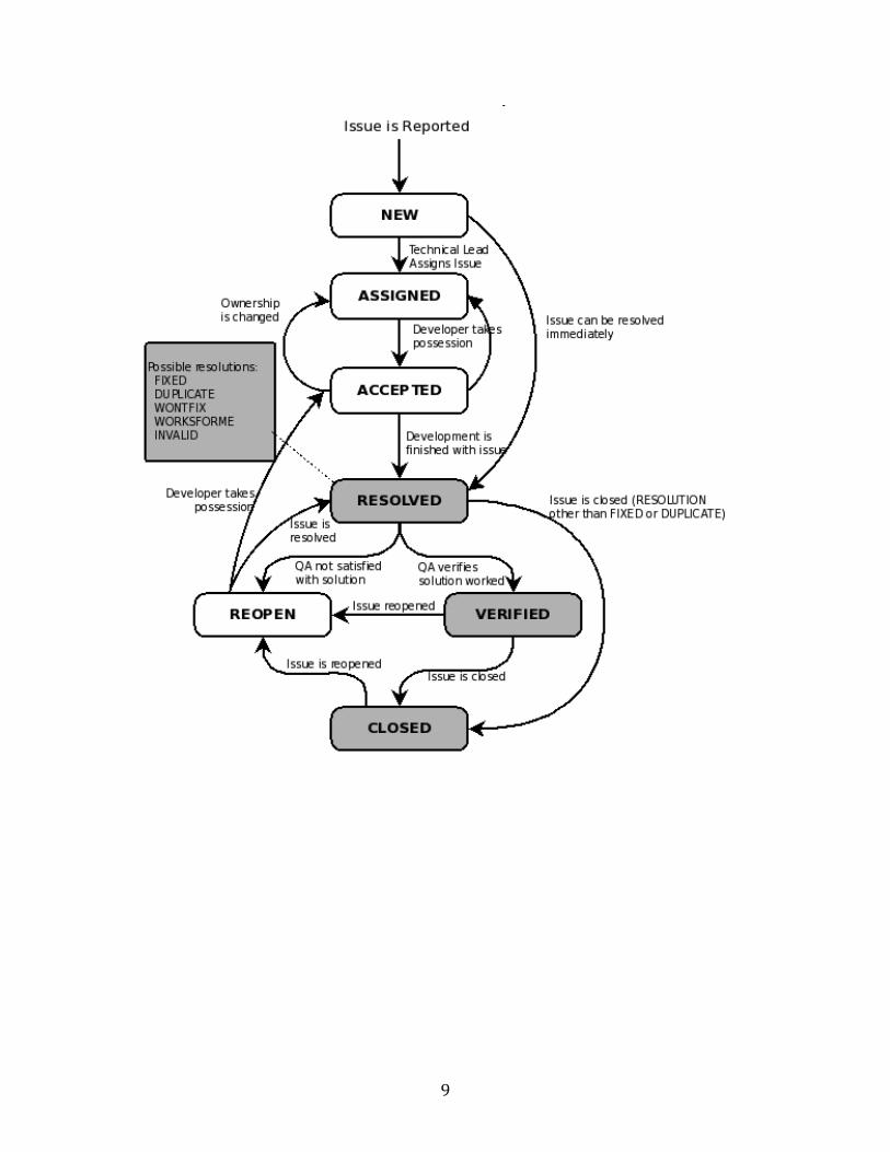
9
10
The above workflow can be summarized as follows: 1. Issue report is created with status = NEW and assigned to the technical lead. 2. Technical lead triages the issue and assigns it to a team member – status changes to
ASSIGNED. 3. The team member to whom the issue has been assigned reviews the issue and
possession of it by changing status to ACCEPTED. At the very least, this indicates that the team member is aware that a new issue has been assigned to them.
4. The assignee works to investigate and resolve the issue. At this point two basic scenarios are possible:
a. The team member takes action that they feel resolves the issue, and they change the status to RESOLVED with a resolution of FIXED. The team member must add a comment to explain exactly what was done to resolve the issue. If the issue was with a documentation component of the model (i.e. the white papers, parameters document, etc.) the Subversion revision number that contains the corrected document(s) must be included in the resolution comment. If the issue was with the GoldSim model, the version of the model in which the fix was implemented must be included in the comment. Attempting to commit a change of status to RESOLVED without including a comment will transfer to an error page which directs the user to click the browser’s “back” button and add a comment.
b. The team member determines that the issue should be marked as resolved using one of the other resolutions (DUPLICATE, WONTFIX, WORKSFORME or INVALID – for the meanings of these, please see the previous section.). Again, the team member must enter a comment explaining the rationale behind this decision. At this point, we skip ahead to step 7 below.
5. As part of changing the status of an issue to status RESOLVED, the team member must re-assign the issue to another team member to independently verify that the issue has been successfully resolved. If the team member has any doubts as to whom they should assign the report at this point, they should assign it back to the technical lead, who will determine who should verify the issue’s resolution.
6. The new assignee attempts to independently verify that the issue is resolved. a. If they agree, they changed the issue status to VERIFIED, and we progress to
step 7 below. b. Otherwise, they change the status to REOPENED and assign the issue back to
the team member who marked it as resolved, taking us back to step 3 in the process
In either case, the validator must provide a comment explaining in as much detail as necessary why the issue either passed or failed verification.
7. This issue has its status changed to CLOSED and its lifecycle is ostensibly ended. However, future testing might lead to the conclusion that the issue was not in fact fully resolved, in which case the issue will have its status changed to REOPENED and it will be assigned to the technical lead for triage, taking us back to step 2.
Interacting with Issue Reports Once an issue report has been created and saved in the database, it can be accessed in several ways:
11
• Via the link to the issue report included in the automated emails that Bugzilla sends when the issue report is created or modified
• By entering the report’s issue number in the text field to the left of the “Find” button in the top and bottom toolbar of each page of the ES Issue Tracker
• By searching for the issue
Searching for Issues The ES Issue Tracker provides a large “Search” button on its home page and “search” links in the top and bottom toolbars of each page of the site. All of these lead the user to the search page. The search page has two tabs, entitled “Find a Specific Issue” (the default) and “Advanced Search.”
Simple Search The first tab (from this point on referred to as the “simple search interface”) has a form with three fields, Status, Product, and Words. “Status“ is a drop-down list with the terms Open, Closed, and All. “Open” reports are all those whose status field contains “Open Status” as described in the previous section. For the purposes of the search interface, “Closed” reports are all those reports whose status field contains “Resolves Status” as described in the previous section. Choosing “All” means that the query will not filter on status. “Product” is another drop down list containing the values “All” and “Clive PA Model.” Since the ES Issue Tracker is limited to single product, this field can essentially be ignored. “Words” is a text field where the user can issue words that it wants to include in the query. Bugzilla will search all “content” fields – the report summary, the description, and any comments that have been added to the report (see below) for any of the words entered in this field.
Advanced Search The advanced search page provides the ability to create highly detailed searches by specifying desired values for any of the different fields as well as specifying date ranges for criteria such as when various aspects of the issue report changed (e.g. status, priority, severity, etc.) Team members who are new to this interface may find it daunting. Because documenting all features of the advanced search would unnecessarily lengthen this SOP, team members are advised to consult the team’s IT specialist for personal training and assistance in using the interface if needed.
Saved Searches Saved searches are an extremely powerful and useful Bugzilla feature. Once a search has been defined using either the simple or advanced interface, the search can be given a name and saved. The saved search will then show up as a link in the top and bottom toolbars. Bugzilla provides one built-in saved search, called “My Issues,” that searches for all “open” issue reports where the user is either the issue reporter or the current assignee. It is easy to create other useful saved searches, such as all open issues dealing a given component, or all issues assigned to a particular team member. Because Bugzilla stores these searches as
12
URLs, with the search criteria included in the URL’s query string, saved searches can easily be shared among team members by simply sending an email or IM with the search URL, which can then be used to execute and save the search in the target user’s profile.
The Issue Tracker as the Sole Means of Communication for Issue Tracking and Resolution As mentioned in the introduction, a major goal of the issue tracking system is to provide documentation of how an issue was identified, the steps taken to correct it, and the steps taken to verify that the issue was in the end resolved in a satisfactory manner. Therefore, once an issue has been identified, the Issue Tracker should be the sole means of written communication about the issue. The team accomplishes this by adding comments to the issue report, and reassigning the issue among team members as necessary.
Adding Comments to the Issue Report As the issue report transitions between states and is otherwise modified, team members should add comments to the issue report that explain the state transitions and modifications. For example, if the priority or severity fields are changed, a comment should be added to explain why the priority is considered to be different (raised or lowered) than it was previously. Most crucially, as mentioned earlier, when an issue is marked RESOLOVED, a comment MUST be added to explain exactly what was done to resolve the issue. This constraint is enforced by the software – attempting to commit a change of status to RESOLVED without including a comment will transfer to an error page which directs the user to click the browser’s “back” button and add a comment. If the issue was with a documentation component of the model (i.e. the white papers, parameters document, etc.) the Subversion revision number that contains the corrected document(s) must be included in the resolution comment. If the issue was with the GoldSim model, the version of the model in which the fix was implemented must be included in the comment. Comments are also extremely useful for tracking progress in resolving non-trivial issues. If debugging the issue involves significant testing and/or research, recording intermediate results and progress in comments is an excellent way to preserve and share important technical information. This also has the added benefit of keeping the technical lead and project manager (plus potentially other interested parties) informed of progress on the issue, as Bugzilla generates automated email notifications every time a change to the issue report is committed to the database.
Adding Attachments to the Issue Report Bugzilla also allows users to upload attachments to issue reports. This feature is especially useful for attaching screen shots, spreadsheets, and other non-text information to the report. Other candidates for attachments might be intermediate versions of documents that are in the process of being amended and correspondence from interested parties who might not have access to the Issue Tracker. Also, incremental versions of the GoldSim model (versions whose version number ends in a letter – see section 4.3 of the “GoldSim Model Development SOP” for details) may be attached to an issue report as a way to share
13
these versions during the process of issue resolution. Because of their size, GoldSim Models should always be marked as “Big Files” by checking the “BigFile” check box on the attachment upload interface. This means that they will be stored directly on the server’s hard disk and can be deleted by the site administrator when appropriate (for example, when a newer intermediate version is available, or the issue has been closed).
Reassigning an Issue Sometimes a developer may need to reassign an issue to get help from another team member. The other team member may go on to resolve the issue, or may simply provide information or other help that allows the original assignee to complete the resolution. In this latter case, the team member to whom the issue was re-assigned should assign the issue back to the original team member once they have provided the requested assistance (which should of course be recorded in one or more comments in the issue report).

Appendix D - EnergySolutions Checkprint Standard Operating Procedure
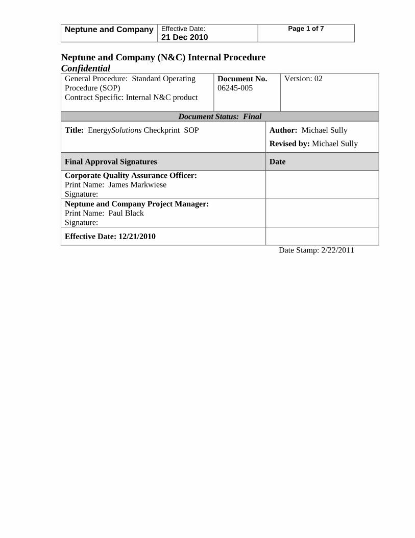
Neptune and Company Effective Date: 21 Dec 2010
Page 1 of 7
Neptune and Company (N&C) Internal Procedure Confidential General Procedure: Standard Operating Procedure (SOP) Contract Specific: Internal N&C product
Document No. 06245-005
Version: 02
Document Status: Final
Title: EnergySolutions Checkprint SOP Author: Michael Sully Revised by: Michael Sully
Final Approval Signatures Date
Corporate Quality Assurance Officer: Print Name: James Markwiese Signature:
Neptune and Company Project Manager: Print Name: Paul Black Signature:
Effective Date: 12/21/2010
Date Stamp: 2/22/2011
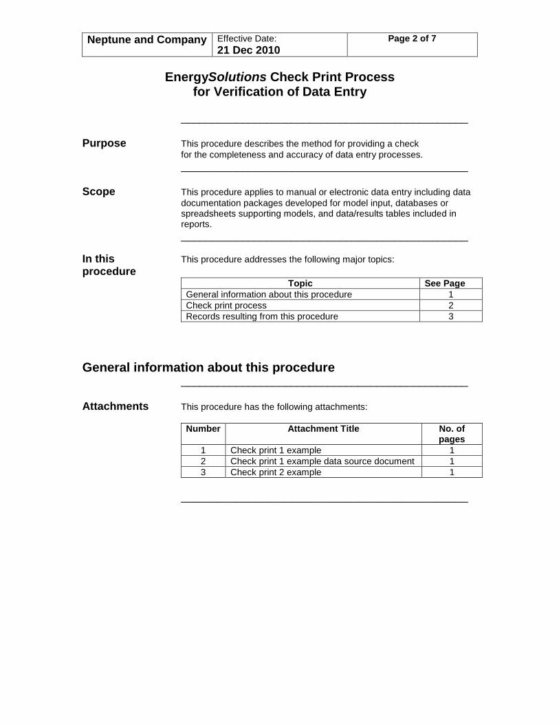
Neptune and Company Effective Date: 21 Dec 2010
Page 2 of 7
EnergySolutions Check Print Process
for Verification of Data Entry _______________________________________________ Purpose This procedure describes the method for providing a check for the completeness and accuracy of data entry processes. _______________________________________________ Scope This procedure applies to manual or electronic data entry including data
documentation packages developed for model input, databases or spreadsheets supporting models, and data/results tables included in reports.
_______________________________________________ In this This procedure addresses the following major topics: procedure
Topic See Page General information about this procedure 1 Check print process 2 Records resulting from this procedure 3
General information about this procedure _______________________________________________ Attachments This procedure has the following attachments:
Number Attachment Title No. of pages
1 Check print 1 example 1 2 Check print 1 example data source document 1 3 Check print 2 example 1
_______________________________________________

Neptune and Company Effective Date: 21 Dec 2010
Page 3 of 7
History of This table lists the revision history and effective dates of this procedure revision
Revision Date Description of Changes 0 8 Sep
2004 New document
1 21 Dec 2010
Revised signature page
_______________________________________________ Who requires Personnel verifying data entry processes. training to this procedure? _______________________________________________ Training The training method for this procedure is on-the-job training by a method previously trained individual and is documented by signature on training
form and archived with project records _______________________________________________ Prerequisites None. _______________________________________________ Check print process
_______________________________________________ Overview
This procedure applies to work processes requiring the manual entry or electronic transfer of data. Examples of entities that receive data include data documentation packages for model input parameters, external spreadsheets and databases used to provide input parameters for modeling, and tables of data/results in documents. Using this procedure data entry or transfer is verified by comparing values in the receiving entity with values in the source documents/files to insure accuracy and completeness of the data entry or transfer. An individual other than the one compiling the data in the receiving entity should perform this check. For manual data entry 100 percent of the entries are checked. For electronic data transfer, 10 percent of the entries are checked. Inputs are checked using the check print process described below. This process can be used to verify most data entry tasks. Large files may require a modified procedure.
_______________________________________________
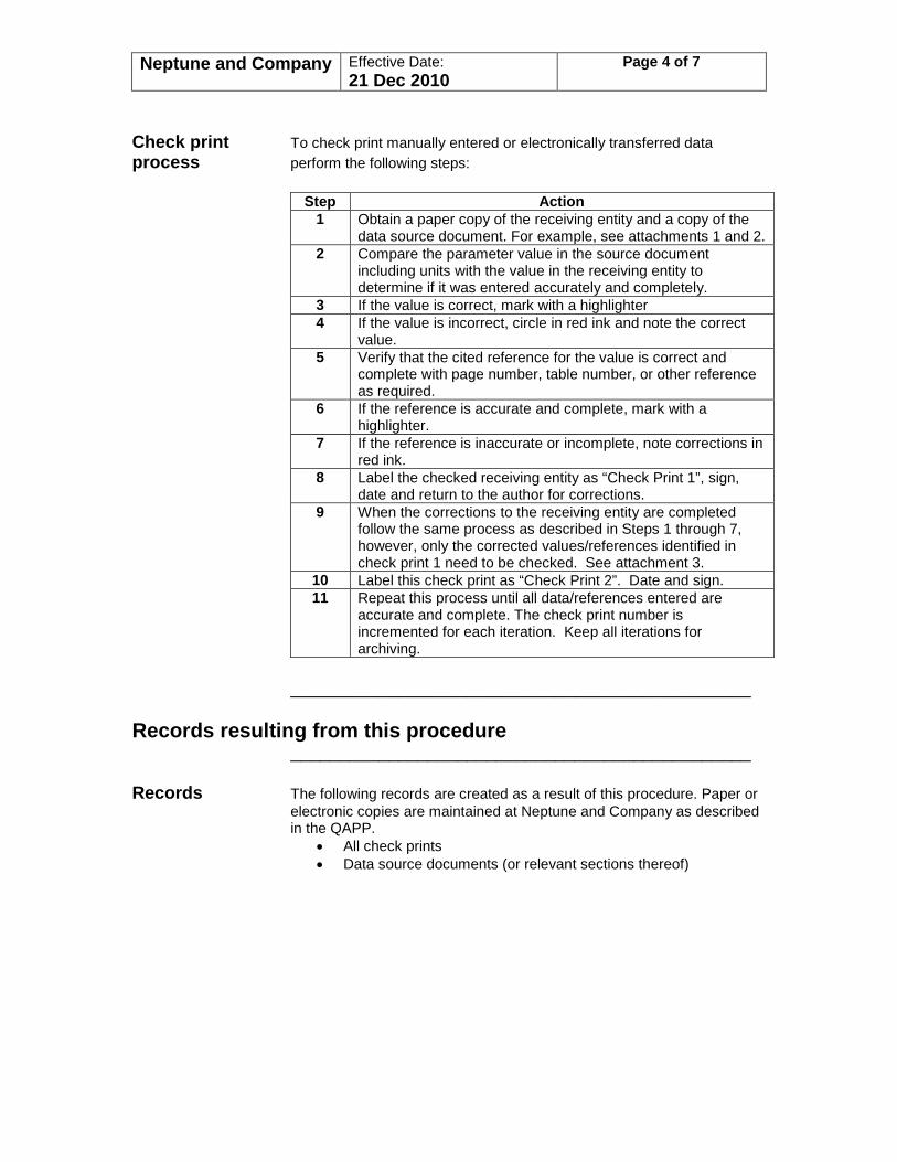
Neptune and Company Effective Date: 21 Dec 2010
Page 4 of 7
Check print To check print manually entered or electronically transferred data process perform the following steps:
Step Action 1 Obtain a paper copy of the receiving entity and a copy of the
data source document. For example, see attachments 1 and 2. 2 Compare the parameter value in the source document
including units with the value in the receiving entity to determine if it was entered accurately and completely.
3 If the value is correct, mark with a highlighter 4 If the value is incorrect, circle in red ink and note the correct
value. 5 Verify that the cited reference for the value is correct and
complete with page number, table number, or other reference as required.
6 If the reference is accurate and complete, mark with a highlighter.
7 If the reference is inaccurate or incomplete, note corrections in red ink.
8 Label the checked receiving entity as “Check Print 1”, sign, date and return to the author for corrections.
9 When the corrections to the receiving entity are completed follow the same process as described in Steps 1 through 7, however, only the corrected values/references identified in check print 1 need to be checked. See attachment 3.
10 Label this check print as “Check Print 2”. Date and sign. 11 Repeat this process until all data/references entered are
accurate and complete. The check print number is incremented for each iteration. Keep all iterations for archiving.
_______________________________________________
Records resulting from this procedure _______________________________________________
Records The following records are created as a result of this procedure. Paper or electronic copies are maintained at Neptune and Company as described in the QAPP.
• All check prints • Data source documents (or relevant sections thereof)
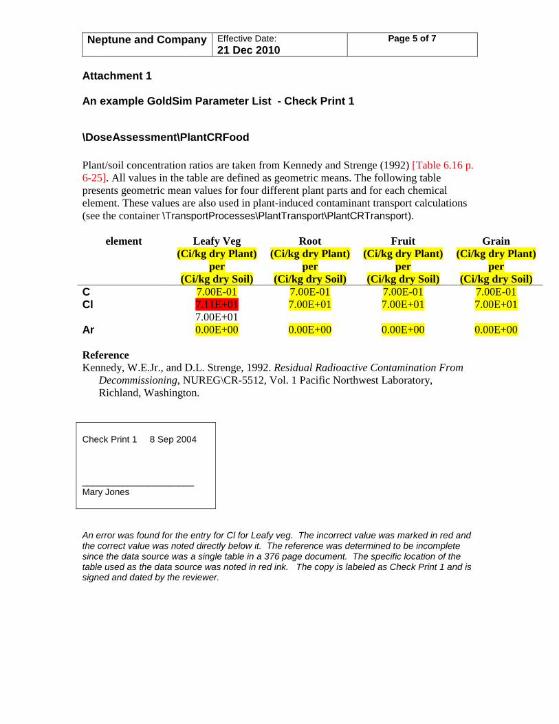
Neptune and Company Effective Date: 21 Dec 2010
Page 5 of 7
Attachment 1 An example GoldSim Parameter List - Check Print 1
\DoseAssessment\PlantCRFood Plant/soil concentration ratios are taken from Kennedy and Strenge (1992) [Table 6.16 p. 6-25]. All values in the table are defined as geometric means. The following table presents geometric mean values for four different plant parts and for each chemical element. These values are also used in plant-induced contaminant transport calculations (see the container \TransportProcesses\PlantTransport\PlantCRTransport).
element Leafy Veg Root Fruit Grain (Ci/kg dry Plant)
per (Ci/kg dry Soil)
(Ci/kg dry Plant) per
(Ci/kg dry Soil)
(Ci/kg dry Plant) per
(Ci/kg dry Soil)
(Ci/kg dry Plant) per
(Ci/kg dry Soil) C 7.00E-01 7.00E-01 7.00E-01 7.00E-01 Cl 7.11E+01
7.00E+01 7.00E+01 7.00E+01 7.00E+01
Ar 0.00E+00 0.00E+00 0.00E+00 0.00E+00 Reference Kennedy, W.E.Jr., and D.L. Strenge, 1992. Residual Radioactive Contamination From
Decommissioning, NUREG\CR-5512, Vol. 1 Pacific Northwest Laboratory, Richland, Washington.
Check Print 1 8 Sep 2004 ______________________ Mary Jones An error was found for the entry for Cl for Leafy veg. The incorrect value was marked in red and the correct value was noted directly below it. The reference was determined to be incomplete since the data source was a single table in a 376 page document. The specific location of the table used as the data source was noted in red ink. The copy is labeled as Check Print 1 and is signed and dated by the reviewer.
Neptune and Company Effective Date: 21 Dec 2010
Page 6 of 7
Attachment 2 Source Document Referenced in the Parameter List Kennedy and Strenge (1992)
Neptune and Company Effective Date: 21 Dec 2010
Page 7 of 7
Attachment 3 An example GoldSim Parameter List - Check Print 2
\DoseAssessment\PlantCRFood Plant/soil concentration ratios are taken from Kennedy and Strenge (1992) [Table 6.16, p. 6-25]. All values in the table are defined as geometric means. The following table presents geometric mean values for four different plant parts and for each chemical element. These values are also used in plant-induced contaminant transport calculations (see the container \TransportProcesses\PlantTransport\PlantCRTransport).
element Leafy Veg Root Fruit Grain (Ci/kg dry Plant)
per (Ci/kg dry Soil)
(Ci/kg dry Plant) per
(Ci/kg dry Soil)
(Ci/kg dry Plant) per
(Ci/kg dry Soil)
(Ci/kg dry Plant) per
(Ci/kg dry Soil) C 7.00E-01 7.00E-01 7.00E-01 7.00E-01 Cl 7.00E+01 7.00E+01 7.00E+01 7.00E+01 Ar 0.00E+00 0.00E+00 0.00E+00 0.00E+00 Reference Kennedy, W.E.Jr., and D.L. Strenge, 1992. Residual Radioactive Contamination From Decommissioning, NUREG\CR-5512, Vol. 1 Pacific Northwest Laboratory, Richland, Washington. Check Print 2 8 Sep 2004 ______________________ Mary Jones The correction of the entry for Cl for Leafy veg and the additional data source information are verified and marked. The check print number is incremented and the copy is signed and dated by the reviewer. This is the final check print since the document is now accurate and complete.