Embed Size (px)
Citation preview

10 Keypad, Displays, & Drive Parameters
65
10.1 KEYPAD
The keypad serves two purposes:
1. You can configure the drive for specific applicationsand change its performance in many ways, such asadjusting the times of acceleration and decelerationand presetting levels of security access.
Subject to safety considerations, adjustments maybe made with the drive running or stopped. If run-ning, the drive responds immediately to the newsetting.
2. You can get full information about the settings andthe operational status of the drive. Extensive diag-nostic information is available in the event of adrive fault.
For parameter adjustment, the keypad has fivekeys. Use the or keys to select a Menu (func-tional group of parameters). The menu numberappears to the left of the decimal point in the Indexwindow.
Use the or keys to select a parameter fromthe chosen menu. The parameter number appears tothe right of the decimal point in the Index window, andthe value of the chosen parameter appears in theData window.
Press the MODE key once to access the dis-played parameter value for adjustment. The valueflashes if access is permitted.
Figure 10-1.Quantum III Decal
NOTE
If access is not permitted, check the following:
1. The parameter is “read only."
2. The parameter is invisible and protected bya level of security (see paragraph 10.5).
3.The parameter is assigned to a programma-ble input.
4. The parameter is being driven by an appli-cation program with the serial interface.
Use the or keys to adjust the value. Toadjust quickly, press and hold a key.
Press the MODE key again to exit from theadjustment mode.
SAVING PARAMETERS
To store (make permanently effective) the para-meter value changes, set parameter 00 of any menu =1 and press reset. If this sequence is not enacted, thechanges will be lost when the power is removed fromthe drive.
Quantum III Digital DC Drive
Drive Ready
Alarm (OVLD)
Zero Speed
Run Forward
Run Reverse
Bridge 1
Bridge 2
At Set Speed
Current Limit
PARAMETER DATA
PARAMETER INDEX
Use and keys to select a menu. Eachmenu is a functional group of parameters. Themenu number appears to the left of the decimalpoint in the Index window.
Use and keys to select a Parameter fromthe chosen menu. The parameter numberappears to the right of the decimal point in theIndex window, and its value appears in thedata window.
Press Mode key once to access the displayedparameter for adjustment. The Data displayflashes if access is permitted.
Use and keys to adjust the value. Holdkey down to adjust rapidly.
Press Mode key again to exit adjustment mode.
Numerical parameters have ranges of 000-255,000-1999 or ±1000 or ±1999.
Bit parameters are displayed as a single digit,0-1. Unauthorized adjustment is prevented bymeans of a Security Code which must becorrectly entered in Parameter 0 before accessis permitted.
To store parameter values, set Parameter 0 to1 and press the Reset key.
MODE RESET
INSTRUCTIONS
Quantum III
66
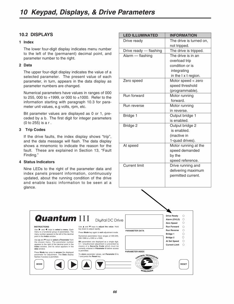
LED ILLUMINATED INFORMATIONDrive ready The drive is turned on,
not tripped.Drive ready — flashing The drive is tripped.Alarm — flashing The drive is in an
overload trip condition or isintegratingin the I x t region.
Zero speed Motor speed < zerospeed threshold (programmable).
Run forward Motor runningforward.
Run reverse Motor running in reverse.
Bridge 1 Output bridge 1 is enabled.
Bridge 2 Output bridge 2is enabled.(inactive in 1-quad drives).
At speed Motor running at thespeed demanded by the speed reference.
Current limit Drive running anddelivering maximumpermitted current.
10 Keypad, Displays, & Drive Parameters
10.2 DISPLAYS
1 Index
The lower four-digit display indicates menu numberto the left of the (permanent) decimal point, andparameter number to the right.
2 Data
The upper four-digit display indicates the value of aselected parameter. The present value of eachparameter, in turn, appears in the data display asparameter numbers are changed.
Numerical parameters have values in ranges of 000to 255, 000 to +1999, or 000 to ±1000. Refer to theinformation starting with paragraph 10.3 for para-meter unit values, e.g volts, rpm, etc.
Bit parameter values are displayed as 0 or 1, pre-ceded by a b. The first digit for integer parameters(0 to 255) is a r .
3 Trip Codes
If the drive faults, the index display shows “trip”,and the data message will flash. The data displayshows a mnemonic to indicate the reason for thefault. These are explained in Section 13, “FaultFinding.”
4 Status Indicators
Nine LEDs to the right of the parameter data andindex panels present information, continuouslyupdated, about the running condition of the driveand enable basic information to be seen at aglance.
Quantum III Digital DC Drive
Drive Ready
Alarm (OVLD)
Zero Speed
Run Forward
Run Reverse
Bridge 1
Bridge 2
At Set Speed
Current Limit
PARAMETER DATA
PARAMETER INDEX
Use and keys to select a menu. Eachmenu is a functional group of parameters. Themenu number appears to the left of the decimalpoint in the Index window.
Use and keys to select a Parameter fromthe chosen menu. The parameter numberappears to the right of the decimal point in theIndex window, and its value appears in thedata window.
Press Mode key once to access the displayedparameter for adjustment. The Data displayflashes if access is permitted.
Use and keys to adjust the value. Holdkey down to adjust rapidly.
Press Mode key again to exit adjustment mode.
Numerical parameters have ranges of 000-255,000-1999 or ±1000 or ±1999.
Bit parameters are displayed as a single digit,0-1. Unauthorized adjustment is prevented bymeans of a Security Code which must becorrectly entered in Parameter 0 before accessis permitted.
To store parameter values, set Parameter 0 to1 and press the Reset key.
MODE RESET
INSTRUCTIONS
Quantum III
10 Keypad, Displays, & Drive Parameters
67
10.3 DRIVE PARAMETERS
The list of menus is given in paragraph 10.6.Parameter names, ranges, default values and securityare given in paragraph 10.6.2. A full description andexplanation, when required, is found in paragraph10.7. Block diagrams are shown for each menu inFigures 10-4 through 10-18.
Before attempting to adjust parameters, pleaserefer to paragraph 10.1 for details on keypad entryand paragraph 10.5 for details on security.
10.4 TYPES OF PARAMETERS
Real Values:
A real value parameter has a numerical value andcan be unipolar or bipolar. Its range can be from-1999 to +1999. Real values are comparable topotentiometers in analog drives, but are much moreprecise and not subject to drift. They are used toset variables such as speed, acceleration, or cur-rent limit.
Bit Values:
A bit value is one which can have a value of either1 or 0 and is therefore reserved for drive statusvariables which are either true or false, enabled ordisabled, etc. Bit values are used to representsuch variables as quadrant enable, ramp enable,drive at speed, etc.
Each parameter falls into one of two further cate-gories, as follows:
Read-only values:
Read-only values are ones which are set or mea-sured by the drive itself, either during power-upreset or continuously during drive operation. As thename implies, these values may only be read, andallows one to MONITOR ONLY drive status andperformance.
Read/Write Values:
Read/write values are those which are set by key-pad entry, serial interface communication or back-ground program execution to optimize the driveperformance for a given application. Read/writevalues may also be monitored by means of the key-pad and displays or via the serial interface to verifydrive status and performance.
10.4.1 Visible and Invisible Parameters
The parameter set with which Quantum III dri-ves are equipped is divided into two further groups foroperational convenience.
Those which are ordinarily needed for settingthe drive up at the installation and start-up stage canbe called up whenever the drive is powered on.These are called the “visible” parameters.
The second group contains the “ invisible”parameters, so called because at Level 1 securitythey do not appear in the Index display, even if calledup. These are the parameters required for fine tuninga drive to operate, for example, in a process system,usually in conjunction with one or more other drives ofthe same or different type.
Visible and invisible parameters are distin-guished in the text and in the control logic diagramsfor Menus 1 to 16. Visible parameter numbers are inplain typeface, e.g. 01.01, and invisible parameters initalics, e.g. 01.01. They are also classified in para-graph 10.6.2.
Visible Parameters
Visible parameters, both RO and R/W, are alwaysavailable to read when the drive is powered on.Visible R/W parameters are normally protected byone or more levels of security and cannot bechanged until the correct codes have been entered.This is Level 1 security, unless and until a higherlevel code is set.
Invisible Parameters
Invisible parameters always require Level 2 securi-ty code, and wil l require Level 3 (if set).With the correct code(s), invisible RO parametersare accessible to read, and invisible R/W parame-ters are accessible to write.
68
10 Keypad, Displays, & Drive Parameters
10.4.3 Organization
Parameters are organized into functionally-relat-ed sets, or menus, so that access to parameters relat-ed to a specific function is logical and quick. Themenus are listed in paragraph 10.6.1.
10.4.4 Adjustment
Any menu and any visible parameter can beselected and will display its value to read withoutneed for a Security Code. The procedure is the sameif a parameter value is to be changed, except thatentering a Security Code will normally have to be thefirst action.
Any menu, and any invisible parameter can beselected and its value displayed to read and writewhen the correct security code has been entered.
Whenever the user returns to a menu (betweenpower-on and power-off), the software immediatelygoes to the last parameter to have been selected inthat menu. This is convenient when making a seriesof adjustments to a particular group of parameters.
10.4.5 Access to Parameters
Initially, when the drive is first powered on, and ifLevel 3 security is not set, access to write is immedi-ately available to a small group of the visible parame-ters. Refer to paragraph 10.5.1 and Figure 10-3.
If Level 3 security is set, all parameters arealways protected.
10.4.6 Procedure
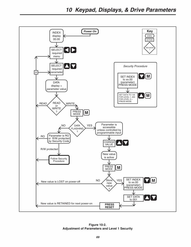
The procedure for selecting and changing aparameter is shown in Figure 10-2 and described onthe following pages. It is also described on the key-pad of the Quantum III.
For most parameters, the drive accepts anduses the value entered, and the motor will respond tothe new value immediately. The exception is achange of Baud Rate (11.12), Serial Mode (11.13),Threshold 1 Destination (12.07) and Threshold 2Destination (12.12). To enable the drive to act on thechange in these cases, press RESET after writing thenew value.
Any new value is not saved however, and will belost at power-off.
The keypad is ready to select another menu orparameter.
10.4.2 Default Values
When power is removed and then reapplied tothe drive, the parameters will revert to standardpower-on default values—altered by any parameterchanges that have been stored. See paragraph10.4.7. The Quantum III defaults are listed in para-graph 10.6.2.
The parameters have been set to standard set-tings during manufacture of the basic world-widedrive. These values differ slightly from the power-ondefaults listed in paragraph 10.6.2. It may be desir-able to reset the Quantum III to these values. To re-establish factory defaults, select parameter 00 of anymenu, press mode, and enter 255 for factory non-regenerative defaults or 233 for factory regenerativedefaults, followed by reset.
NOTEDrive must be in STOP condition before re-establishing defaults.
QUANTUM III FACTORY SETTINGS
After factory defaults are reset, the followingmust be changed to enable the drive to function as aQuantum III.
Changes to Default Values:
02.13=1 (Jog Ramp)03.13=1 (AVF Feedback)03.15=500 (Max Arm Volts)05.19=1 (Standstill Mode on Stop)06.07=1000 (Cross-over Voltage)06.15=1 (Enable Field Economy)06.21=815 (Field Firing Angle Endstop)07.12=119 (Analog Input #2)07.13=120 (Analog Input #3)07.14=40808.12=111 (F2: #22=Run Permit)08.13=113 (F3: #23=Inch/Jog)08.14=112 (F4: #24=Reverse)08.15=115 (F5: #25=Ref #3)08.16=1034 (F6: #26=Ext Trip)08.21=1 (Disable Logic Functions)09.24=1 (Invert Status #ST5)11.01=304 Arm Volts DC11.02=502 Arm Amps DC11.03=303 Machine RPM11.04=102 Speed Reference11.05=706 AC Line Voltage11.06=106 Max Reference Limit11.07=105 Jog Speed11.08=204 Accel Time11.09=205 Decel Time11.10=405 Current Limit
Then save, using procedure discussed in paragraph8.3.3.
10 Keypad, Displays, & Drive Parameters
69
Figure 10-2.Adjustment of Parameters and Level 1 Security
Power OnINDEXdisplay 00.00
SELECT required
menu
DATAdisplay =
parameter value
READor
WRITE?
Follow SecurityProcedure
WRITEREAD
YESNO
New valueis active
DATAFLASHING
?
CHANGEVALUE
Storenew
value?
YES SET INDEXto xx.00
(parameter)PRESS MODE
STATE
ACTION
DECISION?
Key
SELECT required
parameter
Parameter is RO or R/W protectedby Security Code
or
RO
R/W protected
Parameter isaccessible
unless controlled byprogrammable input
SET DATAto 001
SET INDEXto xx.00
(parameter)PRESS MODE
SET DATAto 149
PRESS MODE
Level 1 Security Procedure
M
M
MNO
PRESSMODE M
New value is LOST on power-off
New value is RETAINED for next power-on
PRESSMODE M
PRESSRESET
Security Procedure
SET DATA TO 149FOR LEVEL 1, 200FOR LEVEL 2—PRESS MODE
PROCEDURES FOR SELECTING AND CHANGING PARAMETERS
OPERATION KEYS DISPLAYWINDOW
Select menu or Index, left of decimal point
Select parameter or Index, right of decimal point
Read only — DataRead/Write MODE, Change value then or Dataonly if display is flashing—refer to 10.5Enter new value MODE Data
70
10 Keypad, Displays, & Drive Parameters
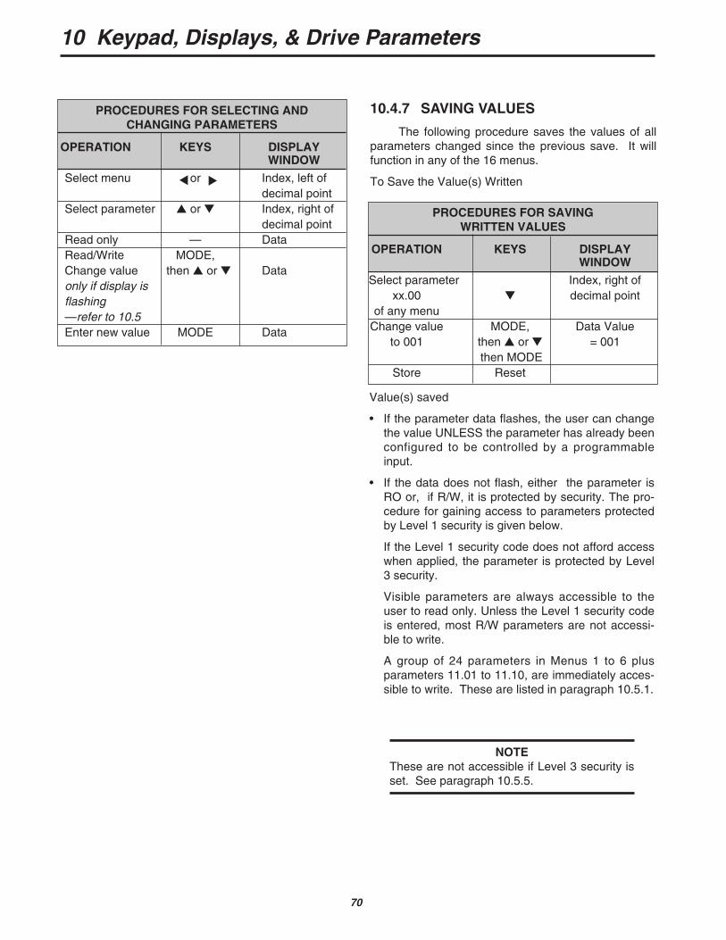
10.4.7 SAVING VALUES
The following procedure saves the values of allparameters changed since the previous save. It willfunction in any of the 16 menus.
To Save the Value(s) Written
Value(s) saved
• If the parameter data flashes, the user can changethe value UNLESS the parameter has already beenconfigured to be controlled by a programmableinput.
• If the data does not flash, either the parameter isRO or, if R/W, it is protected by security. The pro-cedure for gaining access to parameters protectedby Level 1 security is given below.
If the Level 1 security code does not afford accesswhen applied, the parameter is protected by Level3 security.
Visible parameters are always accessible to theuser to read only. Unless the Level 1 security codeis entered, most R/W parameters are not accessi-ble to write.
A group of 24 parameters in Menus 1 to 6 plusparameters 11.01 to 11.10, are immediately acces-sible to write. These are listed in paragraph 10.5.1.
NOTEThese are not accessible if Level 3 security isset. See paragraph 10.5.5.
PROCEDURES FOR SAVING WRITTEN VALUES
OPERATION KEYS DISPLAYWINDOW
Select parameter Index, right of xx.00 decimal point
of any menuChange value MODE, Data Value
to 001 then or = 001then MODE
Store Reset

10.5.2 Level 1 Security to Access theVisible R/W Parameters (Figure 10-2)
• Select any menu
• or to set index to zero (xx.00)
• Press mode M
• or to write 149 in data(Level 1 security code) - PARTIAL ACCESS
• Press mode M
Visible R/W parameters are now accessible towrite new values.
10.5.3 Level 2 Security to Access theInvisible R/W Parameters (Figure 10-2)
• Select any menu
• or to set index to zero (xx.00)
• Press mode M
• or to write 200 in data (Level 2 security code) - FULL ACCESS
• Press mode M
All R/W parameters are now accessible towrite new values.
RO parameters can be read.
NOTELevel 1 and Level 2 security entry is lost whenpower is removed from the drive. It must bereset after each power-up.
10.5 SECURITY
After selecting a parameter number and pressingMODE:
SECURITY PROCEDURES
10.5.1 Power On
A. The following visible parameters are immediatelyaccessible, NOT protected by Level 1 or Level 2security.
01.05 Inch reference01.06 Maximum speed forward01.09 Maximum speed reverse01.11 Reference ‘ON’01.12 REVERSE selector01.13 INCH selector
02.04 Forward acceleration 102.05 Forward deceleration 102.06 Reverse deceleration 102.07 Reverse acceleration 1
03.09 Speed loop P gain (proportional)
03.10 Speed loop I gain (integral)03.11 Speed loop D gain
(differential)03.14 Feedback encoder scaling03.15 Maximum armature voltage03.16 Maximum speed (scaling rpm)03.17 IR compensation
04.05 I limit Bridge 104.06 I limit Bridge 2
05.05 Maximum current ( scaled )
06.06 IR compensation 206.07 Back-emf set point06.08 Maximum field current 106.10 Minimum field current
and 11.01 to 11.10 — User Menu 00
B. Of the rest of the parameters —
• RO - (read only) parameters are accessible to be read.
• R/W - (read/write) parameters are read-onlyuntil a Level 1 security code is entered.
10 Keypad, Displays, & Drive Parameters
71
• or to write any 3-digit number from 1 to 255in data (excluding 149—the Level 1 securitycode)
• Press mode M
• Save (paragraph 10.4.7)
There is now no access to any parameter, not evento read only, until the assigned Level 3 code hasbeen entered.
B. Level 3 Security Access—
• or plus or to set index to xx.00
• Press mode M
• or to write the assigned code number indata (Level 3 security code)
• Press mode M
The user now has access through Level 1 and 2Security, one of which has to be entered next.
CAUTION
When Level 3 security is set, you mustmaintain access to your 3-digit assignedcode number. If you forget or lose thisnumber, the factory must be consulted fora means of retrieving the number.
See Appendix F for more details on Security.
10.5.4 To Enable Free Access to ALL Parameters
A. To remove security—
• Power on
• or to set index to xx.00
• Press mode M
• or to write 200 in data (Level 2 securitycode)
• Press mode M
• or plus or to set index to 11.17
• Press mode M
• to write 0
If the parameters are now saved (paragraph10.4.7), there is no protection for ANY parameter.
NOTEAll parameters are accessible even afterpower is removed and reapplied.
B. To reinstate security—
Repeat the procedure in paragraph 10.5.4 butmake parameter 11.17=149, and save (paragraph10.4.7).
10.5.5 Level 3 Security
An additional private security code, Level 3, isavailable to the user. The code is user-programmablefrom 1 to 255 except 149 (the Level 1 code). Ifapplied, the effect prevents access to all parametersuntil the Level 3 code has been entered prior to enter-ing the Level 1 or Level 2 code.
A. To assign a Level 3 security code number—
• Power up
• or to set index to xx.00
• Press mode M
• or to write 200 in data (Level 2 security code)
• Press mode M
• or plus or to set index to 11.17. Data display shows 149.
• Press mode M
72
10 Keypad, Displays, & Drive Parameters
10 Keypad, Displays, & Drive Parameters
73
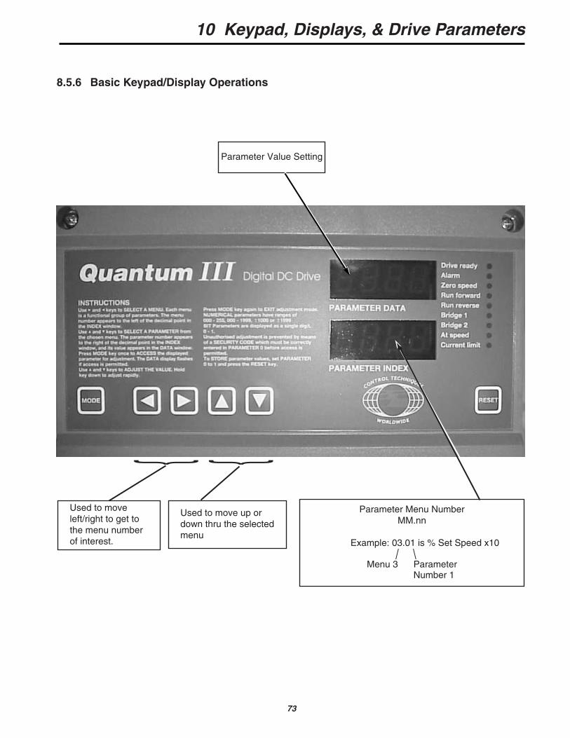
8.5.6 Basic Keypad/Display Operations
Parameter Value Setting
Used to moveleft/right to get tothe menu numberof interest.
Used to move up ordown thru the selectedmenu
Parameter Menu NumberMM.nn
Example: 03.01 is % Set Speed x10 / \
Menu 3 ParameterNumber 1
10 Keypad, Displays, & Drive Parameters
74
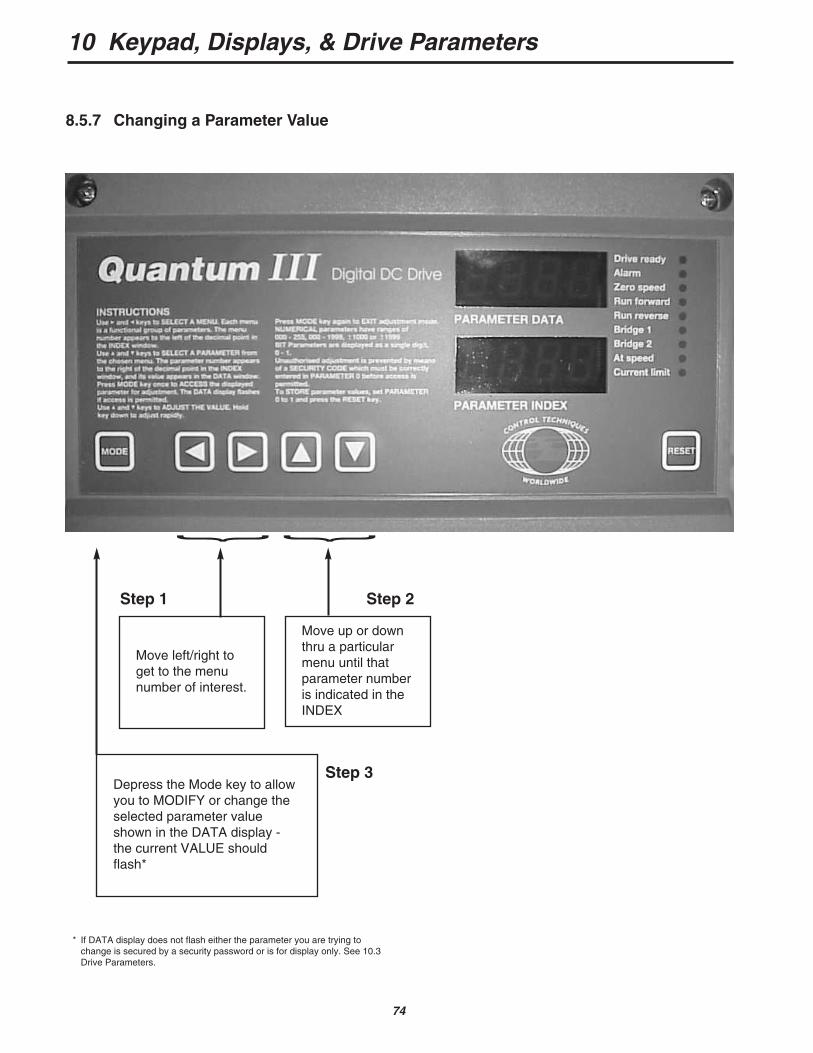
8.5.7 Changing a Parameter Value
Step 1 Step 2
Step 3
* If DATA display does not flash either the parameter you are trying tochange is secured by a security password or is for display only. See 10.3Drive Parameters.
Move left/right toget to the menunumber of interest.
Depress the Mode key to allowyou to MODIFY or change theselected parameter valueshown in the DATA display -the current VALUE shouldflash*
Move up or downthru a particularmenu until thatparameter numberis indicated in theINDEX
10 Keypad, Displays, & Drive Parameters
75
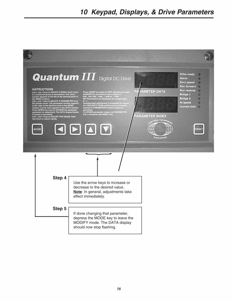
Step 4Use the arrow keys to increase ordecrease to the desired value.Note: In general, adjustments takeeffect immediately.
Step 5If done changing that parameter,depress the MODE key to leave theMODIFY mode. The DATA displayshould now stop flashing.
10 Keypad, Displays, & Drive Parameters
76
10.6 MENU INDEX
The menu index lists the 16 different menusavailable and a description of the function of the para-meters associated with each menu. For detaileddescription of parameters, refer to paragraph 10.7.
10.6.1 Menus List
MENU DESCRIPTION
00 User Menu—to give fast access to the most-used parameters
01 Speed Reference—selection of source and limits
02 Acceleration and Deceleration Ramps03 Speed Feedback Selection and Speed
Loop04 Current — selection and limits05 Current Loop06 Field Control07 Analog Inputs and Outputs08 Logic Inputs09 Status Outputs10 Status Logic & Fault Information11 Miscellaneous12 Programmable Thresholds13 Digital Lock14 MD21 System Set-up15 Applications Menu 116 Applications Menu 2
10.6.2 Parameters—Names, Range & Default Values
References in brackets (xx.xx) in the Default col-umn indicate parameters which default to other para-meters.
Parameters shown in bold type are those whichare freely accessible only immediately after power-on.
NOTEParameters shown with an asterisk (*) andhighlighted in gray must be reset to the defaultshown if factory defaults are enacted. Referto paragraph 10.4.2.
Parameters at the end of each menu list in italictype are invisible. Refer to paragraphs 10.4 and 10.5.
10 Keypad, Displays, & Drive Parameters
77
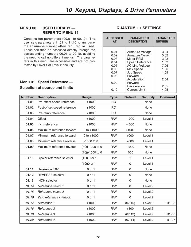
MENU 00 USER LIBRARY — REFER TO MENU 11
Contains ten parameters (00.01 to 00.10). Theuser sets parameters 11.01 to 11.10 to any para-meter numbers most often required or used.These can then be accessed directly through thecorresponding numbers 00.01 to 00.10, avoidingthe need to call up different menus. The parame-ters in this menu are accessible and are not pro-tected by Level 1 or Level 2 security.
Menu 01 Speed Reference —
Selection of source and limits
ACCESSED PARAMETER PARAMETERAT DESCRIPTION NUMBER
0.01 Armature Voltage 3.040.02 Armature Current 5.020.03 Motor RPM 3.030.04 Speed Reference 1.020.05 AC Line Voltage 7.060.06 Max Speed 1.060.07 Jog Speed 1.050.08 Forward
Acceleration 2.040.09 Forward
Deceleration 2.050.10 Current Limit 4.05
QUANTUM III SETTINGS
Number Description Range Type Default Security Comment
01.01 Pre-offset speed reference ±1000 RO None
01.02 Post-offset speed reference ±1000 RO None
01.03 Pre-ramp reference ±1000 RO None
01.04 Offset ±1000 R/W + 000 Level 1
01.05 Inch reference ±1000 R/W + 050 None
01.06 Maximum reference forward 0 to +1000 R/W +1000 None
01.07 Minimum reference forward 0 to +1000 R/W +000 Level 1
01.08 Minimum reference reverse -1000 to 0 R/W +000 Level 1
01.09 Maximum reference reverse (4Q)-1000 to 0 R/W -1000 None
(1Q)-1000 to 0 R/W 000 None
01.10 Bipolar reference selector (4Q) 0 or 1 R/W 1 Level 1
(1Q)0 or 1 R/W 0 Level 1
01.11 Reference ‘ON’ 0 or 1 R/W 0 None
01.12 REVERSE selector 0 or 1 R/W 0 None
01.13 INCH selector 0 or 1 R/W 0 None
01.14 Reference select 1 0 or 1 R/W 0 Level 2
01.15 Reference select 2 0 or 1 R/W 0 Level 2
01.16 Zero reference interlock 0 or 1 R/W 0 Level 2
01.17 Reference 1 ±1000 R/W (07.15) Level 2 TB1-03
01.18 Reference 2 ±1000 R/W +300 Level 2
01.19 Reference 3 ±1000 R/W (07.13) Level 2 TB1-06
01.20 Reference 4 ±1000 R/W (07.14) Level 2 TB1-07
10 Keypad, Displays, & Drive Parameters
78
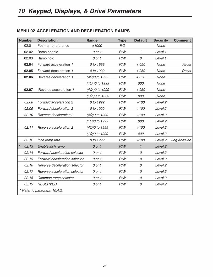
Number Description Range Type Default Security Comment
02.01 Post-ramp reference ±1000 RO None
02.02 Ramp enable 0 or 1 R/W 1 Level 1
02.03 Ramp hold 0 or 1 R/W 0 Level 1
02.04 Forward acceleration 1 0 to 1999 R/W + 050 None Accel
02.05 Forward deceleration 1 0 to 1999 R/W + 050 None Decel
02.06 Reverse deceleration 1 (4Q)0 to 1999 R/W + 050 None
(1Q )0 to 1999 R/W 000 None
02.07 Reverse acceleration 1 (4Q )0 to 1999 R/W + 050 None
(1Q )0 to 1999 R/W 000 None
02.08 Forward acceleration 2 0 to 1999 R/W +100 Level 2
02.09 Forward deceleration 2 0 to 1999 R/W +100 Level 2
02.10 Reverse deceleration 2 (4Q)0 to 1999 R/W +100 Level 2
(1Q)0 to 1999 R/W 000 Level 2
02.11 Reverse acceleration 2 (4Q)0 to 1999 R/W +100 Level 2
(1Q)0 to 1999 R/W 000 Level 2
02.12 Inch ramp rate 0 to 1999 R/W +100 Level 2 Jog Acc/Dec
* 02.13 Enable inch ramp 0 or 1 R/W 1 Level 2
02.14 Forward acceleration selector 0 or 1 R/W 0 Level 2
02.15 Forward deceleration selector 0 or 1 R/W 0 Level 2
02.16 Reverse deceleration selector 0 or 1 R/W 0 Level 2
02.17 Reverse acceleration selector 0 or 1 R/W 0 Level 2
02.18 Common ramp selector 0 or 1 R/W 0 Level 2
02.19 RESERVED 0 or 1 R/W 0 Level 2
* Refer to paragraph 10.4.2.
MENU 02 ACCELERATION AND DECELERATION RAMPS
10 Keypad, Displays, & Drive Parameters
79
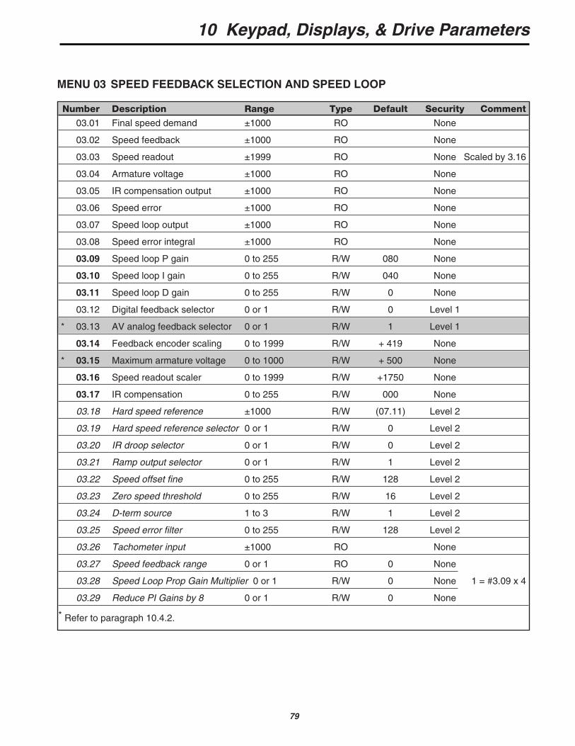
MENU 03 SPEED FEEDBACK SELECTION AND SPEED LOOP
Number Description Range Type Default Security Comment
03.01 Final speed demand ±1000 RO None
03.02 Speed feedback ±1000 RO None
03.03 Speed readout ±1999 RO None Scaled by 3.16
03.04 Armature voltage ±1000 RO None
03.05 IR compensation output ±1000 RO None
03.06 Speed error ±1000 RO None
03.07 Speed loop output ±1000 RO None
03.08 Speed error integral ±1000 RO None
03.09 Speed loop P gain 0 to 255 R/W 080 None
03.10 Speed loop I gain 0 to 255 R/W 040 None
03.11 Speed loop D gain 0 to 255 R/W 0 None
03.12 Digital feedback selector 0 or 1 R/W 0 Level 1
* 03.13 AV analog feedback selector 0 or 1 R/W 1 Level 1
03.14 Feedback encoder scaling 0 to 1999 R/W + 419 None
* 03.15 Maximum armature voltage 0 to 1000 R/W + 500 None
03.16 Speed readout scaler 0 to 1999 R/W +1750 None
03.17 IR compensation 0 to 255 R/W 000 None
03.18 Hard speed reference ±1000 R/W (07.11) Level 2
03.19 Hard speed reference selector 0 or 1 R/W 0 Level 2
03.20 IR droop selector 0 or 1 R/W 0 Level 2
03.21 Ramp output selector 0 or 1 R/W 1 Level 2
03.22 Speed offset fine 0 to 255 R/W 128 Level 2
03.23 Zero speed threshold 0 to 255 R/W 16 Level 2
03.24 D-term source 1 to 3 R/W 1 Level 2
03.25 Speed error filter 0 to 255 R/W 128 Level 2
03.26 Tachometer input ±1000 RO None
03.27 Speed feedback range 0 or 1 RO 0 None
03.28 Speed Loop Prop Gain Multiplier 0 or 1 R/W 0 None 1 = #3.09 x 4
03.29 Reduce PI Gains by 8 0 or 1 R/W 0 None
* Refer to paragraph 10.4.2.
10 Keypad, Displays, & Drive Parameters
80
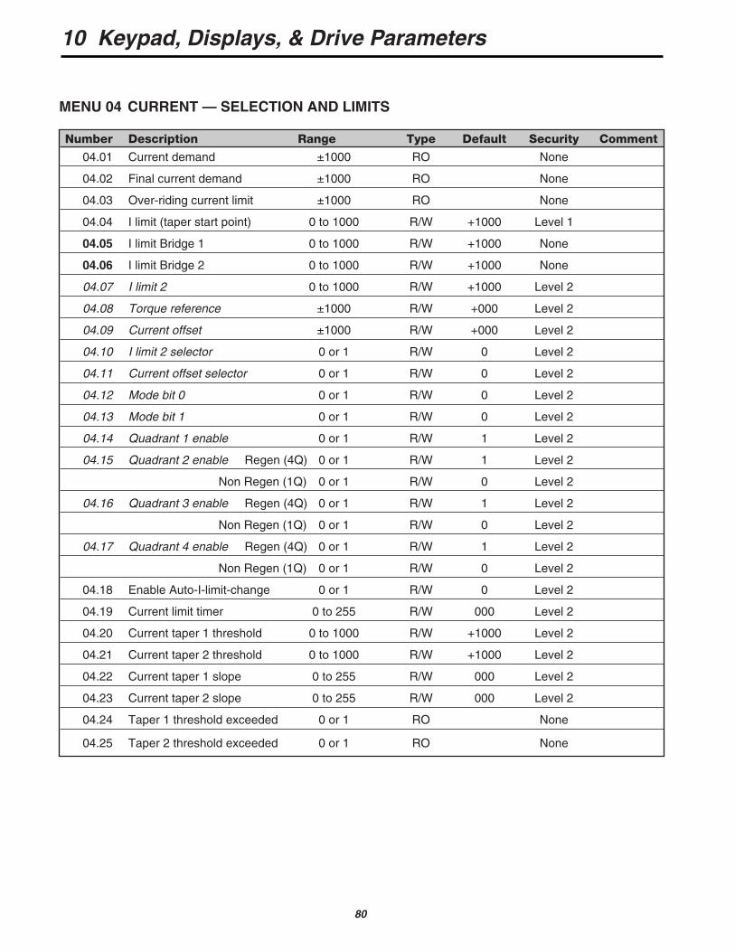
Number Description Range Type Default Security Comment
04.01 Current demand ±1000 RO None
04.02 Final current demand ±1000 RO None
04.03 Over-riding current limit ±1000 RO None
04.04 I limit (taper start point) 0 to 1000 R/W +1000 Level 1
04.05 I limit Bridge 1 0 to 1000 R/W +1000 None
04.06 I limit Bridge 2 0 to 1000 R/W +1000 None
04.07 I limit 2 0 to 1000 R/W +1000 Level 2
04.08 Torque reference ±1000 R/W +000 Level 2
04.09 Current offset ±1000 R/W +000 Level 2
04.10 I limit 2 selector 0 or 1 R/W 0 Level 2
04.11 Current offset selector 0 or 1 R/W 0 Level 2
04.12 Mode bit 0 0 or 1 R/W 0 Level 2
04.13 Mode bit 1 0 or 1 R/W 0 Level 2
04.14 Quadrant 1 enable 0 or 1 R/W 1 Level 2
04.15 Quadrant 2 enable Regen (4Q) 0 or 1 R/W 1 Level 2
Non Regen (1Q) 0 or 1 R/W 0 Level 2
04.16 Quadrant 3 enable Regen (4Q) 0 or 1 R/W 1 Level 2
Non Regen (1Q) 0 or 1 R/W 0 Level 2
04.17 Quadrant 4 enable Regen (4Q) 0 or 1 R/W 1 Level 2
Non Regen (1Q) 0 or 1 R/W 0 Level 2
04.18 Enable Auto-I-limit-change 0 or 1 R/W 0 Level 2
04.19 Current limit timer 0 to 255 R/W 000 Level 2
04.20 Current taper 1 threshold 0 to 1000 R/W +1000 Level 2
04.21 Current taper 2 threshold 0 to 1000 R/W +1000 Level 2
04.22 Current taper 1 slope 0 to 255 R/W 000 Level 2
04.23 Current taper 2 slope 0 to 255 R/W 000 Level 2
04.24 Taper 1 threshold exceeded 0 or 1 RO None
04.25 Taper 2 threshold exceeded 0 or 1 RO None
MENU 04 CURRENT — SELECTION AND LIMITS
10 Keypad, Displays, & Drive Parameters
81
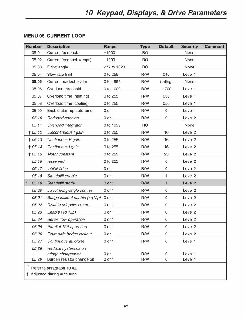
Number Description Range Type Default Security Comment
05.01 Current feedback ±1000 RO None
05.02 Current feedback (amps) ±1999 RO None
05.03 Firing angle 277 to 1023 RO None
05.04 Slew rate limit 0 to 255 R/W 040 Level 1
05.05 Current readout scaler 0 to 1999 R/W (rating) None
05.06 Overload threshold 0 to 1000 R/W + 700 Level 1
05.07 Overload time (heating) 0 to 255 R/W 030 Level 1
05.08 Overload time (cooling) 0 to 255 R/W 050 Level 1
05.09 Enable start-up auto-tune 0 or 1 R/W 0 Level 1
05.10 Reduced endstop 0 or 1 R/W 0 Level 2
05.11 Overload integrator 0 to 1999 RO None
† 05.12 Discontinuous I gain 0 to 255 R/W 16 Level 2
† 05.13 Continuous P gain 0 to 255 R/W 16 Level 2
† 05.14 Continuous I gain 0 to 255 R/W 16 Level 2
† 05.15 Motor constant 0 to 255 R/W 25 Level 2
05.16 Reserved 0 to 255 R/W 0 Level 2
05.17 Inhibit firing 0 or 1 R/W 0 Level 2
05.18 Standstill enable 0 or 1 R/W 1 Level 2
* 05.19 Standstill mode 0 or 1 R/W 1 Level 2
05.20 Direct firing-angle control 0 or 1 R/W 0 Level 2
05.21 Bridge lockout enable (4q12p) 0 or 1 R/W 0 Level 2
05.22 Disable adaptive control 0 or 1 R/W 0 Level 2
05.23 Enable (1q 12p) 0 or 1 R/W 0 Level 2
05.24 Series 12P operation 0 or 1 R/W 0 Level 2
05.25 Parallel 12P operation 0 or 1 R/W 0 Level 2
05.26 Extra-safe bridge lockout 0 or 1 R/W 0 Level 2
05.27 Continuous autotune 0 or 1 R/W 0 Level 1
05.28 Reduce hysteresis on bridge changeover 0 or 1 R/W 0 Level 1
05.29 Burden resistor change bit 0 or 1 R/W 0 Level 1
* Refer to paragraph 10.4.2.
† Adjusted during auto tune.
MENU 05 CURRENT LOOP
10 Keypad, Displays, & Drive Parameters
82
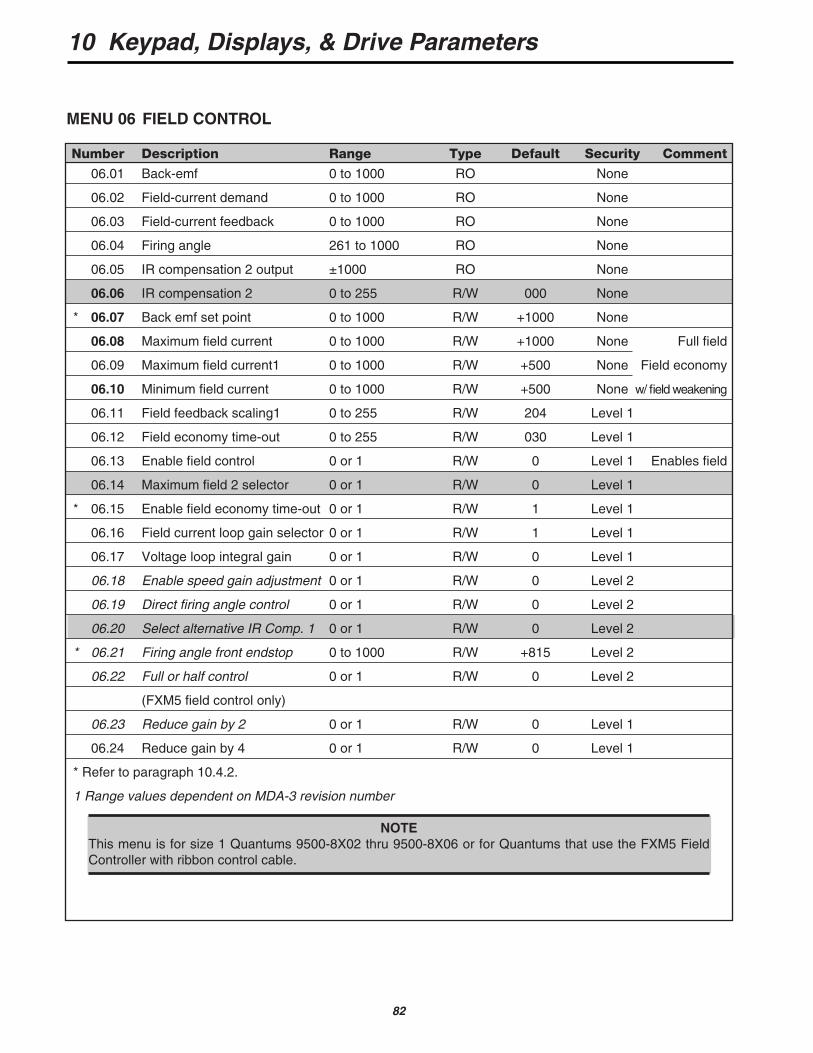
MENU 06 FIELD CONTROL
Number Description Range Type Default Security Comment
06.01 Back-emf 0 to 1000 RO None
06.02 Field-current demand 0 to 1000 RO None
06.03 Field-current feedback 0 to 1000 RO None
06.04 Firing angle 261 to 1000 RO None
06.05 IR compensation 2 output ±1000 RO None
06.06 IR compensation 2 0 to 255 R/W 000 None
* 06.07 Back emf set point 0 to 1000 R/W +1000 None
06.08 Maximum field current 0 to 1000 R/W +1000 None Full field
06.09 Maximum field current1 0 to 1000 R/W +500 None Field economy
06.10 Minimum field current 0 to 1000 R/W +500 None w/ field weakening
06.11 Field feedback scaling1 0 to 255 R/W 204 Level 1
06.12 Field economy time-out 0 to 255 R/W 030 Level 1
06.13 Enable field control 0 or 1 R/W 0 Level 1 Enables field
06.14 Maximum field 2 selector 0 or 1 R/W 0 Level 1
* 06.15 Enable field economy time-out 0 or 1 R/W 1 Level 1
06.16 Field current loop gain selector 0 or 1 R/W 1 Level 1
06.17 Voltage loop integral gain 0 or 1 R/W 0 Level 1
06.18 Enable speed gain adjustment 0 or 1 R/W 0 Level 2
06.19 Direct firing angle control 0 or 1 R/W 0 Level 2
06.20 Select alternative IR Comp. 1 0 or 1 R/W 0 Level 2
* 06.21 Firing angle front endstop 0 to 1000 R/W +815 Level 2
06.22 Full or half control 0 or 1 R/W 0 Level 2
(FXM5 field control only)
06.23 Reduce gain by 2 0 or 1 R/W 0 Level 1
06.24 Reduce gain by 4 0 or 1 R/W 0 Level 1
* Refer to paragraph 10.4.2.
1 Range values dependent on MDA-3 revision number
NOTEThis menu is for size 1 Quantums 9500-8X02 thru 9500-8X06 or for Quantums that use the FXM5 FieldController with ribbon control cable.
10 Keypad, Displays, & Drive Parameters
83
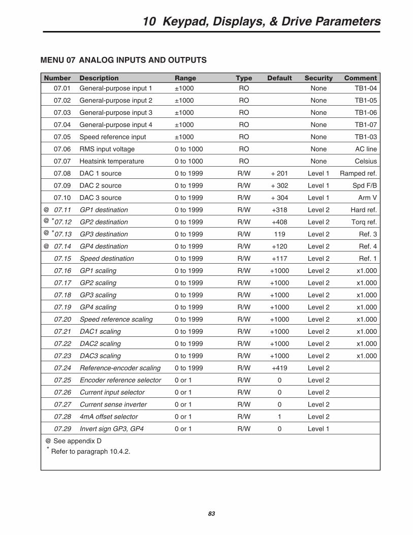
Number Description Range Type Default Security Comment
07.01 General-purpose input 1 ±1000 RO None TB1-04
07.02 General-purpose input 2 ±1000 RO None TB1-05
07.03 General-purpose input 3 ±1000 RO None TB1-06
07.04 General-purpose input 4 ±1000 RO None TB1-07
07.05 Speed reference input ±1000 RO None TB1-03
07.06 RMS input voltage 0 to 1000 RO None AC line
07.07 Heatsink temperature 0 to 1000 RO None Celsius
07.08 DAC 1 source 0 to 1999 R/W + 201 Level 1 Ramped ref.
07.09 DAC 2 source 0 to 1999 R/W + 302 Level 1 Spd F/B
07.10 DAC 3 source 0 to 1999 R/W + 304 Level 1 Arm V
@ 07.11 GP1 destination 0 to 1999 R/W +318 Level 2 Hard ref.
@ *07.12 GP2 destination 0 to 1999 R/W +408 Level 2 Torq ref.
@ *07.13 GP3 destination 0 to 1999 R/W 119 Level 2 Ref. 3
@ 07.14 GP4 destination 0 to 1999 R/W +120 Level 2 Ref. 4
07.15 Speed destination 0 to 1999 R/W +117 Level 2 Ref. 1
07.16 GP1 scaling 0 to 1999 R/W +1000 Level 2 x1.000
07.17 GP2 scaling 0 to 1999 R/W +1000 Level 2 x1.000
07.18 GP3 scaling 0 to 1999 R/W +1000 Level 2 x1.000
07.19 GP4 scaling 0 to 1999 R/W +1000 Level 2 x1.000
07.20 Speed reference scaling 0 to 1999 R/W +1000 Level 2 x1.000
07.21 DAC1 scaling 0 to 1999 R/W +1000 Level 2 x1.000
07.22 DAC2 scaling 0 to 1999 R/W +1000 Level 2 x1.000
07.23 DAC3 scaling 0 to 1999 R/W +1000 Level 2 x1.000
07.24 Reference-encoder scaling 0 to 1999 R/W +419 Level 2
07.25 Encoder reference selector 0 or 1 R/W 0 Level 2
07.26 Current input selector 0 or 1 R/W 0 Level 2
07.27 Current sense inverter 0 or 1 R/W 0 Level 2
07.28 4mA offset selector 0 or 1 R/W 1 Level 2
07.29 Invert sign GP3, GP4 0 or 1 R/W 0 Level 1
@ See appendix D* Refer to paragraph 10.4.2.
MENU 07 ANALOG INPUTS AND OUTPUTS
10 Keypad, Displays, & Drive Parameters
84
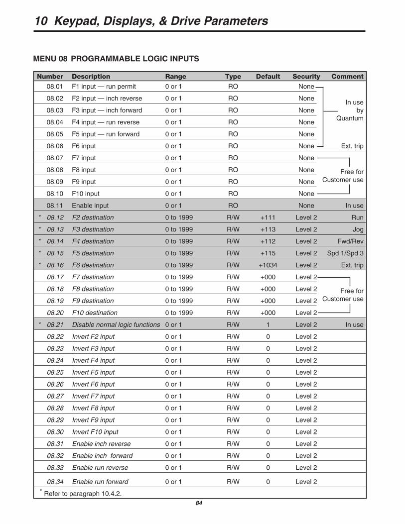
MENU 08 PROGRAMMABLE LOGIC INPUTS
Number Description Range Type Default Security Comment
08.01 F1 input — run permit 0 or 1 RO None
08.02 F2 input — inch reverse 0 or 1 RO NoneIn use
08.03 F3 input — inch forward 0 or 1 RO None by
08.04 F4 input — run reverse 0 or 1 RO NoneQuantum
08.05 F5 input — run forward 0 or 1 RO None
08.06 F6 input 0 or 1 RO None Ext. trip
08.07 F7 input 0 or 1 RO None
08.08 F8 input 0 or 1 RO None Free for
08.09 F9 input 0 or 1 RO None Customer use
08.10 F10 input 0 or 1 RO None
08.11 Enable input 0 or 1 RO None In use
* 08.12 F2 destination 0 to 1999 R/W +111 Level 2 Run
* 08.13 F3 destination 0 to 1999 R/W +113 Level 2 Jog
* 08.14 F4 destination 0 to 1999 R/W +112 Level 2 Fwd/Rev
* 08.15 F5 destination 0 to 1999 R/W +115 Level 2 Spd 1/Spd 3
* 08.16 F6 destination 0 to 1999 R/W +1034 Level 2 Ext. trip
08.17 F7 destination 0 to 1999 R/W +000 Level 2
08.18 F8 destination 0 to 1999 R/W +000 Level 2 Free for
08.19 F9 destination 0 to 1999 R/W +000 Level 2 Customer use
08.20 F10 destination 0 to 1999 R/W +000 Level 2
* 08.21 Disable normal logic functions 0 or 1 R/W 1 Level 2 In use
08.22 Invert F2 input 0 or 1 R/W 0 Level 2
08.23 Invert F3 input 0 or 1 R/W 0 Level 2
08.24 Invert F4 input 0 or 1 R/W 0 Level 2
08.25 Invert F5 input 0 or 1 R/W 0 Level 2
08.26 Invert F6 input 0 or 1 R/W 0 Level 2
08.27 Invert F7 input 0 or 1 R/W 0 Level 2
08.28 Invert F8 input 0 or 1 R/W 0 Level 2
08.29 Invert F9 input 0 or 1 R/W 0 Level 2
08.30 Invert F10 input 0 or 1 R/W 0 Level 2
08.31 Enable inch reverse 0 or 1 R/W 0 Level 2
08.32 Enable inch forward 0 or 1 R/W 0 Level 2
08.33 Enable run reverse 0 or 1 R/W 0 Level 2
08.34 Enable run forward 0 or 1 R/W 0 Level 2
* Refer to paragraph 10.4.2.
10 Keypad, Displays, & Drive Parameters
85
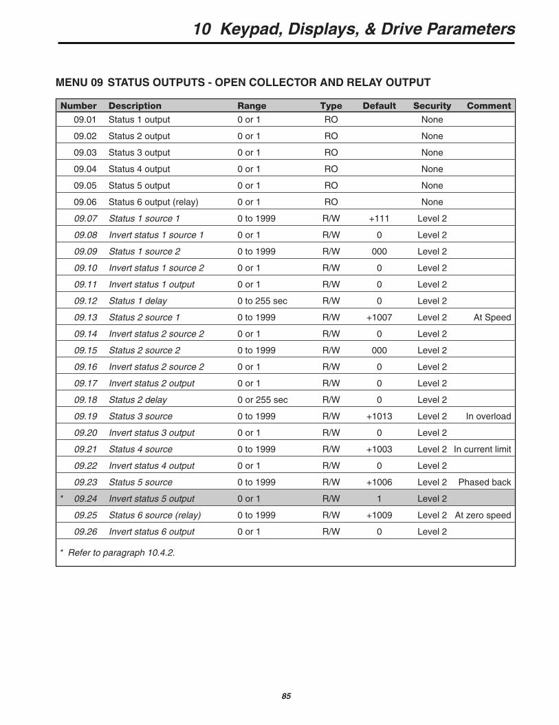
MENU 09 STATUS OUTPUTS - OPEN COLLECTOR AND RELAY OUTPUT
Number Description Range Type Default Security Comment
09.01 Status 1 output 0 or 1 RO None
09.02 Status 2 output 0 or 1 RO None
09.03 Status 3 output 0 or 1 RO None
09.04 Status 4 output 0 or 1 RO None
09.05 Status 5 output 0 or 1 RO None
09.06 Status 6 output (relay) 0 or 1 RO None
09.07 Status 1 source 1 0 to 1999 R/W +111 Level 2
09.08 Invert status 1 source 1 0 or 1 R/W 0 Level 2
09.09 Status 1 source 2 0 to 1999 R/W 000 Level 2
09.10 Invert status 1 source 2 0 or 1 R/W 0 Level 2
09.11 Invert status 1 output 0 or 1 R/W 0 Level 2
09.12 Status 1 delay 0 to 255 sec R/W 0 Level 2
09.13 Status 2 source 1 0 to 1999 R/W +1007 Level 2 At Speed
09.14 Invert status 2 source 2 0 or 1 R/W 0 Level 2
09.15 Status 2 source 2 0 to 1999 R/W 000 Level 2
09.16 Invert status 2 source 2 0 or 1 R/W 0 Level 2
09.17 Invert status 2 output 0 or 1 R/W 0 Level 2
09.18 Status 2 delay 0 or 255 sec R/W 0 Level 2
09.19 Status 3 source 0 to 1999 R/W +1013 Level 2 In overload
09.20 Invert status 3 output 0 or 1 R/W 0 Level 2
09.21 Status 4 source 0 to 1999 R/W +1003 Level 2 In current limit
09.22 Invert status 4 output 0 or 1 R/W 0 Level 2
09.23 Status 5 source 0 to 1999 R/W +1006 Level 2 Phased back
* 09.24 Invert status 5 output 0 or 1 R/W 1 Level 2
09.25 Status 6 source (relay) 0 to 1999 R/W +1009 Level 2 At zero speed
09.26 Invert status 6 output 0 or 1 R/W 0 Level 2
* Refer to paragraph 10.4.2.

10 Keypad, Displays, & Drive Parameters
86
Number Description Range Type Default Security Comment
10.01 Forward velocity 0 or 1 RO None
10.02 Reverse velocity 0 or 1 RO None
10.03 Current limit 0 or 1 RO None In current limit
10.04 Bridge 1 enabled 0 or 1 RO None
10.05 Bridge 2 enabled 0 or 1 RO None
10.06 Electrical phase-back 0 or 1 RO None
10.07 At speed 0 or 1 RO None
10.08 Overspeed 0 or 1 RO None
10.09 Zero speed 0 or 1 RO None At zero speed
10.10 Armature voltage clamp active 0 or 1 RO None
10.11 Phase rotation 0 or 1 RO None
10.12 Drive normal 0 or 1 RO None Drive OK
10.13 Alarm I x t 0 or 1 RO None In overload
10.14 Field loss 0 or 1 RO None
10.15 Feedback loss 0 or 1 RO None
10.16 Phase loss 0 or 1 RO None
10.17 Instantaneous trip 0 or 1 RO None
10.18 Sustained overload 0 or 1 RO None
10.19 Processor 1 watchdog 0 or 1 RO None
10.20 Processor 2 watchdog 0 or 1 RO None
10.21 Motor overtemperature 0 or 1 RO None
10.22 Heatsink overtemperature 0 or 1 RO None
10.23 Speed loop saturated 0 or 1 RO None
10.24 Zero current limit 0 or 1 RO None
10.25 Last trip 0 to 255 RO None
10.26 The trip before last trip (10.25) 0 to 255 RO None Fault
10.27 The trip before 10.26 0 to 255 RO None history
10.28 The trip before 10.27 0 to 255 RO None
10.29 Disable field loss 0 or 1 R/W 0 Level 2
10.30 Disable feedback loss 0 or 1 R/W 0 Level 2
10.31 Disable phase loss 0 or 1 R/W 0 Level 2
10.32 Disable motor overtemperature trip 0 or 1 R/W 1 Level 2
MENU 10 DRIVE STATUS, FAULT INFORMATION, FAULT MONITORS
10 Keypad, Displays, & Drive Parameters
87
Number Description Range Type Default Security Comment
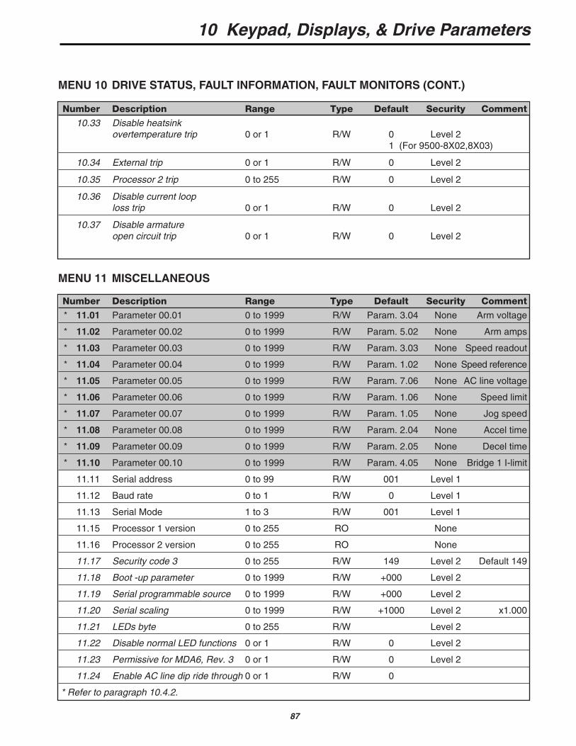
10.33 Disable heatsinkovertemperature trip 0 or 1 R/W 0 Level 2
1 (For 9500-8X02,8X03)
10.34 External trip 0 or 1 R/W 0 Level 2
10.35 Processor 2 trip 0 to 255 R/W 0 Level 2
10.36 Disable current looploss trip 0 or 1 R/W 0 Level 2
10.37 Disable armatureopen circuit trip 0 or 1 R/W 0 Level 2
Number Description Range Type Default Security Comment
* 11.01 Parameter 00.01 0 to 1999 R/W Param. 3.04 None Arm voltage
* 11.02 Parameter 00.02 0 to 1999 R/W Param. 5.02 None Arm amps
* 11.03 Parameter 00.03 0 to 1999 R/W Param. 3.03 None Speed readout
* 11.04 Parameter 00.04 0 to 1999 R/W Param. 1.02 None Speed reference
* 11.05 Parameter 00.05 0 to 1999 R/W Param. 7.06 None AC line voltage
* 11.06 Parameter 00.06 0 to 1999 R/W Param. 1.06 None Speed limit
* 11.07 Parameter 00.07 0 to 1999 R/W Param. 1.05 None Jog speed
* 11.08 Parameter 00.08 0 to 1999 R/W Param. 2.04 None Accel time
* 11.09 Parameter 00.09 0 to 1999 R/W Param. 2.05 None Decel time
* 11.10 Parameter 00.10 0 to 1999 R/W Param. 4.05 None Bridge 1 I-limit
11.11 Serial address 0 to 99 R/W 001 Level 1
11.12 Baud rate 0 to 1 R/W 0 Level 1
11.13 Serial Mode 1 to 3 R/W 001 Level 1
11.15 Processor 1 version 0 to 255 RO None
11.16 Processor 2 version 0 to 255 RO None
11.17 Security code 3 0 to 255 R/W 149 Level 2 Default 149
11.18 Boot -up parameter 0 to 1999 R/W +000 Level 2
11.19 Serial programmable source 0 to 1999 R/W +000 Level 2
11.20 Serial scaling 0 to 1999 R/W +1000 Level 2 x1.000
11.21 LEDs byte 0 to 255 R/W Level 2
11.22 Disable normal LED functions 0 or 1 R/W 0 Level 2
11.23 Permissive for MDA6, Rev. 3 0 or 1 R/W 0 Level 2
11.24 Enable AC line dip ride through 0 or 1 R/W 0
* Refer to paragraph 10.4.2.
MENU 10 DRIVE STATUS, FAULT INFORMATION, FAULT MONITORS (CONT.)
MENU 11 MISCELLANEOUS
10 Keypad, Displays, & Drive Parameters
88
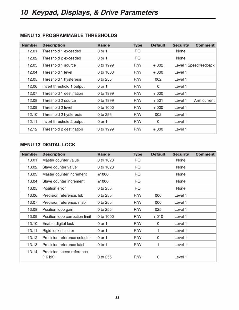
Number Description Range Type Default Security Comment
12.01 Threshold 1 exceeded 0 or 1 RO None
12.02 Threshold 2 exceeded 0 or 1 RO None
12.03 Threshold 1 source 0 to 1999 R/W + 302 Level 1 Speed feedback
12.04 Threshold 1 level 0 to 1000 R/W + 000 Level 1
12.05 Threshold 1 hysteresis 0 to 255 R/W 002 Level 1
12.06 Invert threshold 1 output 0 or 1 R/W 0 Level 1
12.07 Threshold 1 destination 0 to 1999 R/W + 000 Level 1
12.08 Threshold 2 source 0 to 1999 R/W + 501 Level 1 Arm current
12.09 Threshold 2 level 0 to 1000 R/W + 000 Level 1
12.10 Threshold 2 hysteresis 0 to 255 R/W 002 Level 1
12.11 Invert threshold 2 output 0 or 1 R/W 0 Level 1
12.12 Threshold 2 destination 0 to 1999 R/W + 000 Level 1
Number Description Range Type Default Security Comment
13.01 Master counter value 0 to 1023 RO None
13.02 Slave counter value 0 to 1023 RO None
13.03 Master counter increment ±1000 RO None
13.04 Slave counter increment ±1000 RO None
13.05 Position error 0 to 255 RO None
13.06 Precision reference, lsb 0 to 255 R/W 000 Level 1
13.07 Precision reference, msb 0 to 255 R/W 000 Level 1
13.08 Position loop gain 0 to 255 R/W 025 Level 1
13.09 Position loop correction limit 0 to 1000 R/W + 010 Level 1
13.10 Enable digital lock 0 or 1 R/W 0 Level 1
13.11 Rigid lock selector 0 or 1 R/W 1 Level 1
13.12 Precision reference selector 0 or 1 R/W 0 Level 1
13.13 Precision reference latch 0 to 1 R/W 1 Level 1
13.14 Precision speed reference(16 bit) 0 to 255 R/W 0 Level 1
MENU 12 PROGRAMMABLE THRESHOLDS
MENU 13 DIGITAL LOCK

10 Keypad, Displays, & Drive Parameters
89
Number Description Range Type Default Security Comment
14.01 ANSI Serial Address 1
14.02 RS485 Mode 1
14.03 RS485 Baud Rate 48 For modes 1, 5-9
14.04 Clock task time-base-mSec 0
14.05 CTNet Node ID (MD29AN only) 0
14.06 Auto-Run on Power-up Enable 1
14.07 Global Run-time Trip Enable 1
14.08 CT Remote I/O Trip Link Enable-RS-485 0 For CT Remote I/O Module
14.09 Enable Watchdog Trip 0
14.10 Enable Trip on Parameter Write Overrange 1 Recommend Enable
14.11 Disable Toolkit Communications 0 For DPL Toolkit Comms
14.12 Internal Advanced Position Controller Enable 0 Not Menu 13
14.13 I/O Link Synchronization 0 For CT Remote I/O Module
14.14 Encoder Timebase Select 0
14.16 Flash Memory Store Request 0
14.17 Drive —> Drive Communications RS232 0
MENU 14 OPTIONAL MD29 SET-UP PARAMETERS
MD29 MD29AN (CT-Net Version)
General Purpose CT-Remote RS-232 PortRS-485 Port Dedicated Programming
Note: These parameters take effect only after anMD29 or Drive Reset or thru DPL code with theREINIT command.
For additional details on these parameters, consult the MD29 Manual (Part # 0400-0027) or withinthe help sections of the DPL toolkit.
General Purpose CTNet RS-232 PortRS-485 Port LAN Programming
Listed below are a group of parameters governing the operation of the MD-29 and MD-29ANCo-Processors. Specific details about these parameters can be found in the MD29 Manual.
10 Keypad, Displays, & Drive Parameters
90
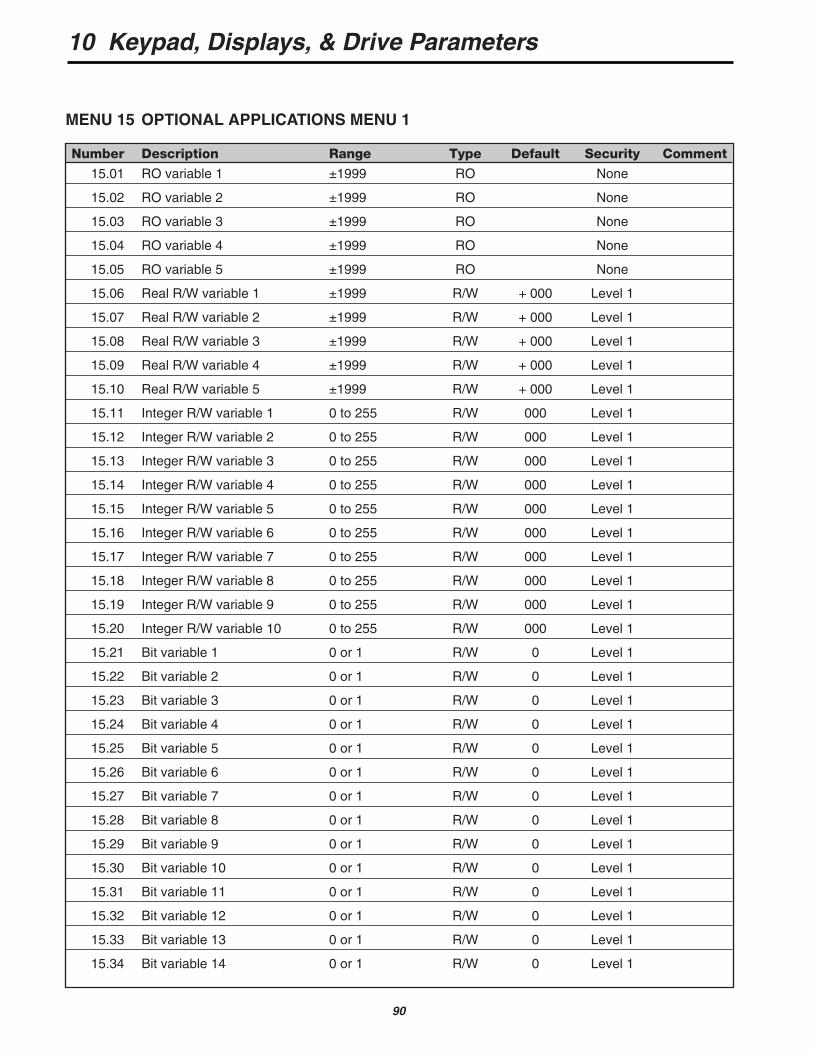
Number Description Range Type Default Security Comment
15.01 RO variable 1 ±1999 RO None
15.02 RO variable 2 ±1999 RO None
15.03 RO variable 3 ±1999 RO None
15.04 RO variable 4 ±1999 RO None
15.05 RO variable 5 ±1999 RO None
15.06 Real R/W variable 1 ±1999 R/W + 000 Level 1
15.07 Real R/W variable 2 ±1999 R/W + 000 Level 1
15.08 Real R/W variable 3 ±1999 R/W + 000 Level 1
15.09 Real R/W variable 4 ±1999 R/W + 000 Level 1
15.10 Real R/W variable 5 ±1999 R/W + 000 Level 1
15.11 Integer R/W variable 1 0 to 255 R/W 000 Level 1
15.12 Integer R/W variable 2 0 to 255 R/W 000 Level 1
15.13 Integer R/W variable 3 0 to 255 R/W 000 Level 1
15.14 Integer R/W variable 4 0 to 255 R/W 000 Level 1
15.15 Integer R/W variable 5 0 to 255 R/W 000 Level 1
15.16 Integer R/W variable 6 0 to 255 R/W 000 Level 1
15.17 Integer R/W variable 7 0 to 255 R/W 000 Level 1
15.18 Integer R/W variable 8 0 to 255 R/W 000 Level 1
15.19 Integer R/W variable 9 0 to 255 R/W 000 Level 1
15.20 Integer R/W variable 10 0 to 255 R/W 000 Level 1
15.21 Bit variable 1 0 or 1 R/W 0 Level 1
15.22 Bit variable 2 0 or 1 R/W 0 Level 1
15.23 Bit variable 3 0 or 1 R/W 0 Level 1
15.24 Bit variable 4 0 or 1 R/W 0 Level 1
15.25 Bit variable 5 0 or 1 R/W 0 Level 1
15.26 Bit variable 6 0 or 1 R/W 0 Level 1
15.27 Bit variable 7 0 or 1 R/W 0 Level 1
15.28 Bit variable 8 0 or 1 R/W 0 Level 1
15.29 Bit variable 9 0 or 1 R/W 0 Level 1
15.30 Bit variable 10 0 or 1 R/W 0 Level 1
15.31 Bit variable 11 0 or 1 R/W 0 Level 1
15.32 Bit variable 12 0 or 1 R/W 0 Level 1
15.33 Bit variable 13 0 or 1 R/W 0 Level 1
15.34 Bit variable 14 0 or 1 R/W 0 Level 1
MENU 15 OPTIONAL APPLICATIONS MENU 1
10 Keypad, Displays, & Drive Parameters
91
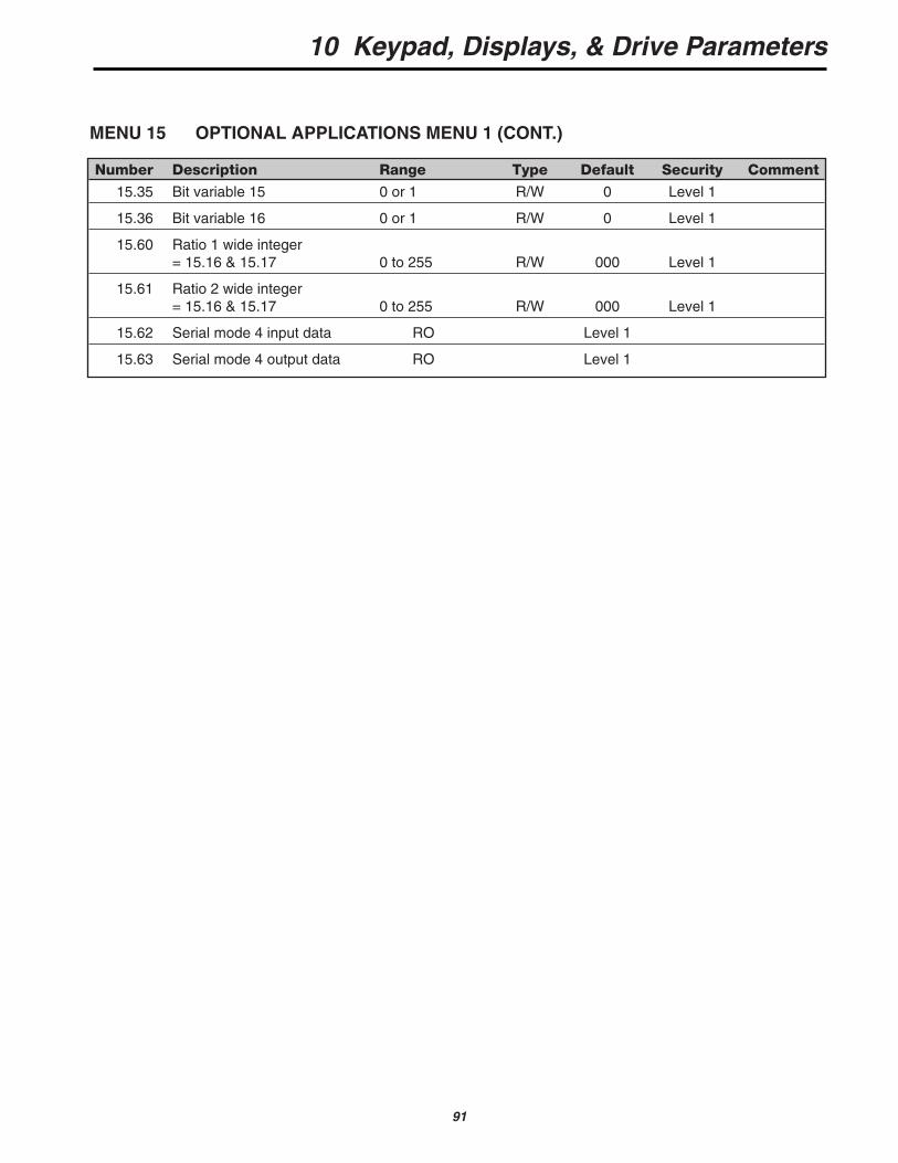
Number Description Range Type Default Security Comment
15.35 Bit variable 15 0 or 1 R/W 0 Level 1
15.36 Bit variable 16 0 or 1 R/W 0 Level 1
15.60 Ratio 1 wide integer= 15.16 & 15.17 0 to 255 R/W 000 Level 1
15.61 Ratio 2 wide integer= 15.16 & 15.17 0 to 255 R/W 000 Level 1
15.62 Serial mode 4 input data RO Level 1
15.63 Serial mode 4 output data RO Level 1
MENU 15 OPTIONAL APPLICATIONS MENU 1 (CONT.)
10 Keypad, Displays, & Drive Parameters
92
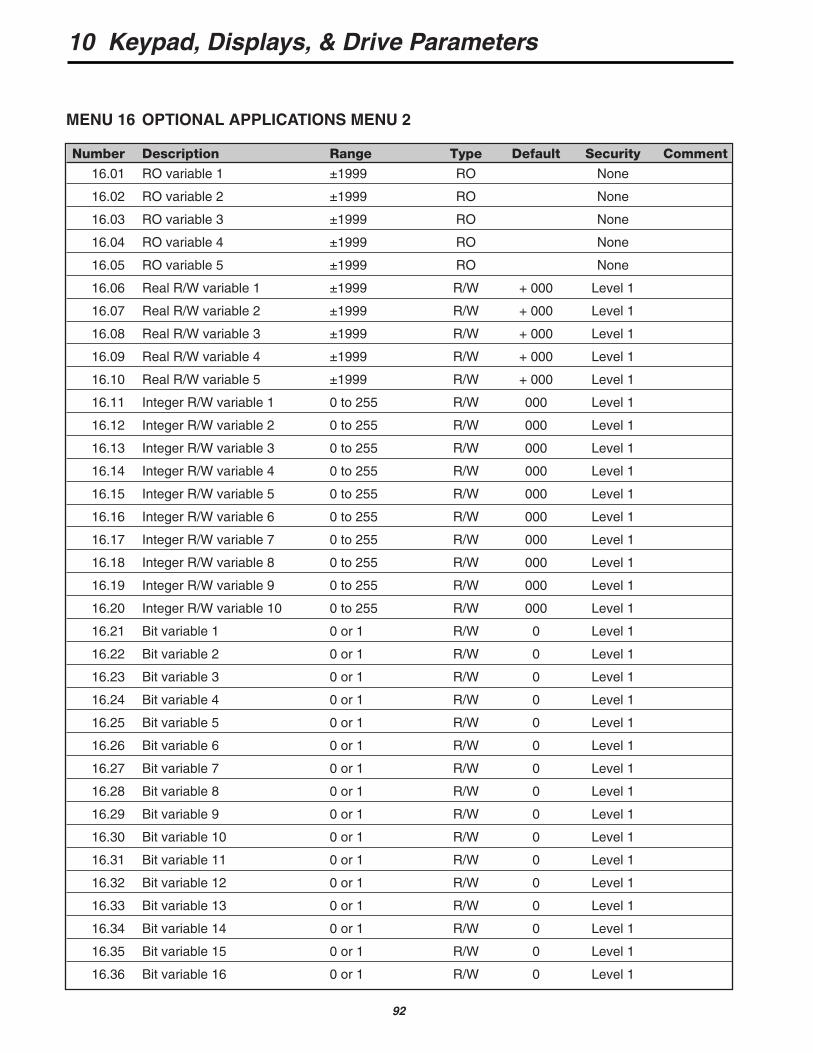
Number Description Range Type Default Security Comment
16.01 RO variable 1 ±1999 RO None
16.02 RO variable 2 ±1999 RO None
16.03 RO variable 3 ±1999 RO None
16.04 RO variable 4 ±1999 RO None
16.05 RO variable 5 ±1999 RO None
16.06 Real R/W variable 1 ±1999 R/W + 000 Level 1
16.07 Real R/W variable 2 ±1999 R/W + 000 Level 1
16.08 Real R/W variable 3 ±1999 R/W + 000 Level 1
16.09 Real R/W variable 4 ±1999 R/W + 000 Level 1
16.10 Real R/W variable 5 ±1999 R/W + 000 Level 1
16.11 Integer R/W variable 1 0 to 255 R/W 000 Level 1
16.12 Integer R/W variable 2 0 to 255 R/W 000 Level 1
16.13 Integer R/W variable 3 0 to 255 R/W 000 Level 1
16.14 Integer R/W variable 4 0 to 255 R/W 000 Level 1
16.15 Integer R/W variable 5 0 to 255 R/W 000 Level 1
16.16 Integer R/W variable 6 0 to 255 R/W 000 Level 1
16.17 Integer R/W variable 7 0 to 255 R/W 000 Level 1
16.18 Integer R/W variable 8 0 to 255 R/W 000 Level 1
16.19 Integer R/W variable 9 0 to 255 R/W 000 Level 1
16.20 Integer R/W variable 10 0 to 255 R/W 000 Level 1
16.21 Bit variable 1 0 or 1 R/W 0 Level 1
16.22 Bit variable 2 0 or 1 R/W 0 Level 1
16.23 Bit variable 3 0 or 1 R/W 0 Level 1
16.24 Bit variable 4 0 or 1 R/W 0 Level 1
16.25 Bit variable 5 0 or 1 R/W 0 Level 1
16.26 Bit variable 6 0 or 1 R/W 0 Level 1
16.27 Bit variable 7 0 or 1 R/W 0 Level 1
16.28 Bit variable 8 0 or 1 R/W 0 Level 1
16.29 Bit variable 9 0 or 1 R/W 0 Level 1
16.30 Bit variable 10 0 or 1 R/W 0 Level 1
16.31 Bit variable 11 0 or 1 R/W 0 Level 1
16.32 Bit variable 12 0 or 1 R/W 0 Level 1
16.33 Bit variable 13 0 or 1 R/W 0 Level 1
16.34 Bit variable 14 0 or 1 R/W 0 Level 1
16.35 Bit variable 15 0 or 1 R/W 0 Level 1
16.36 Bit variable 16 0 or 1 R/W 0 Level 1
MENU 16 OPTIONAL APPLICATIONS MENU 2

10 Keypad, Displays, & Drive Parameters
93
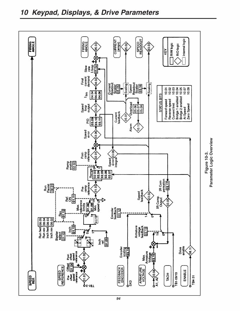
10.7 DESCRIPTION OF PARAMETERS
Please refer to the parameter logic diagram,Figure 10-3, and the individual menu diagrams,Figures 10-4 through 10-18.
A drive, as supplied from the factory, has a stan-dard setting for every parameter; this is its “default”value. The system of control is shown in its defaultcondition in Figure 10-3 before any control or configu-ration changes have been applied.
In the default state and without altering any para-meter, the drive operates a motor under speed andtorque control. Minimum essential inputs are—
• a speed reference (demand) at terminal TB1-3;
• a speed feedback—refer to parameters 03.12and 03.13 to select type;
• a “drive enable” signal at terminal TB4-31;
• a “run permit” signal at terminal TB3-21;
• a “drive run” signal at terminal TB3-25.
The final output of the logic is to define the firingangle, upon which depends the output voltage to thearmature. External inputs (extreme left), parametervalues, and selectors contribute to the final value ofthe firing angle parameter.
The most significant value in normal operation isthe speed reference. The figure shows that the exter-nal speed demand finally controls the firing angle, butthat it may be modified several times and in differentways by other factors.
The first selectable setting enables the speedreference input signal to be configured as a bipolarsignal if required (#1.10). This is followed by a selectoroption which controls the dynamics of the speed refer-ence signal, and enables the operator rapidly to com-municate “run”, “inch/jog”, “forward”, “reverse”, and“stop” signals.
Control of reversal of direction should follow, andafter that a selector which provides a “stop” signal byimposing a “zero speed” demand. Up to this stagethere are also three read-only (RO) parameters,01.01, 01.02, and 01.03, enabling the input signalstate at each point to be displayed.
At this point in the control logic, the externalspeed demand is compared with the chosen “actual”speed parameter to produce the speed error parame-ter. The source of the actual speed feedback can beselected from one of two external sources, encoder ortachometer, or from the internally-computed armaturevoltage parameter 03.04.
The proportional, integral, and derivative (PID)gains are then applied, followed by the four current-limiting parameters. Note that the default values ofthe PID parameters are values which are likely to begood for average loads, but that the default currentlimits are set at maximum. The rate of change of theamplified speed error is finally limited if necessary bythe slew rate parameter. By this stage, the speeddemand has become a current demand, and is nowsummed algebraically with current feedback to gener-ate the reference that controls the SCR bridge firingangle. From the ramp to the firing angle there arefour interposed RO parameters for interrogation andto assist with precise modeling of the control system.
In addition, the most significant factors of drivecondition are available from status bits (refer to Menu10, paragraph 10.7.10).
The purpose and application of the differentmenus and of each individual parameter is explainedin Paragraphs 10.7.0 through 10.7.16.
10 Keypad, Displays, & Drive Parameters
94
Fig
ure
10-
3.P
aram
eter
Lo
gic
Ove
rvie
w

NOTEIn the following descriptions, parametersshown with an asterisk (*) must be reset to thedefault shown if factory defaults are enacted.They are not affected when power on defaultsare selected. Refer to paragraph 10.4.2.
10.7.0 MENU 00—User Menu
This menu allows any 10 parameters from anymenu to be combined in menu 00. They can be moni-tored, written to, and are not protected by security.These parameters are defined in menu 11.
The following parameters have been pro-grammed to this menu at the factory. They may bechanged at any time:
ACCESSED PARAMETER PARAMETERAT DESCRIPTION NUMBER
0.01 Armature Voltage 3.040.02 Armature Current 5.020.03 Motor RPM 3.030.04 Speed Reference 1.020.05 AC Line Voltage 7.060.06 Max Speed 1.060.07 Jog Speed 1.050.08 Forward
Acceleration 2.040.09 Forward
Deceleration 2.050.10 Current Limit 4.05
95
10 Keypad, Displays, & Drive Parameters
10.7.1 MENU 01—Speed Reference
There are four speed reference inputs—parame-ters 01.17, 01.18, 01.19, and 01.20. Each of the fourcan be set from +1000 forward to -1000 reverse with1000 representing full speed. Parameter 01.17 isdefaulted to TB1-3 through a 12-bit D/A. This is thenormal analog speed reference input. The otherthree inputs can be set digitally through the keypad orserial communication, or they will accept analoginputs that are scaled and converted through 10-bitD/A converters. Refer to menu 8, analog inputs.Parameters 01.14 and 01.15 control the selection ofthe four references as the source speed reference.The selected reference can then be modified byadding offset (01.04), selecting bipolar operation(01.10), and setting minimum and maximum limits forboth forward and reverse operation (01.06 through01.09).
Reversing for regenerative drives is achieved byswitching parameter 01.12. Inch or jog speed is acti-vated by 01.13 and set by 01.05. The speed refer-ence at source 01.01 is the input to the zeroreference interlock 01.16, which (when selected,01.16=1) inhibits the drive starting until the speed ref-erence is close to zero. This, in effect, simulates aspeed potentiometer with a zero speed interlock.
The availability of four selective speed refer-ences offers great flexibility when interfacing withother drives or process equipment.
See Figure 10-4 for details of menu 01.
01.01 RO Pre-offset speed referenceRange ±1000Monitors the value of the speed reference continuous-ly. Parameter 01.01 is also used to initiate the zerospeed reference interlock, 01.16. This is the valueapplied at TB1-3--the speed reference input.
01.02 RO Post-offset speed referenceRange ±1000Monitors the value of the speed reference after theoffset, 01.04, has been added.
01.03 RO Pre-ramp referenceRange ±1000The final speed reference before any ramp rates areapplied (refer to Menu 02).

10 Keypad, Displays, & Drive Parameters
96
Fig
ure
10-
4.M
enu
01—
Sp
eed
Ref
eren
ce S
elec
tio
n &
Lim
its
SP
EE
DR
EF.
1
PR
E-R
AM
PR
EF.
01.1
7
01.1
8
01.1
9
01.2
0
RE
F 1
RE
F 2
RE
F 3
RE
F 4
01.1
4
Ref
.se
lect
1
Ref
.se
lect
201
.15
0 0
0
1
101
.01
01.0
4
Offs
et
01.0
20 1
0 1
Inch
ref.
01.0
5
01.1
3
01.1
0
Bip
olar
sele
ct
Inch
01.1
2R
ev.
01
0
1
01.1
1
01.0
601
.07
01.0
801
.09
Max
. fw
d.M
in. f
wd.
Min
. rev
.M
ax. r
ev.
01.0
3
PR
E-R
AM
PR
EF
ER
EN
CE
01.1
6
Zer
o re
f.in
terlo
ckR
ef.
‘ON
’
TB
3-21
RU
N P
ER
MIT
Pre
-offs
etsp
eed
refe
renc
e
Pos
t-of
fset
spee
dre
fere
nce
08.0
1
x (-
1)
R/W
logi
c
R/O
logi
c
Inte
rnal
logi
c
KE
Y
SP
EE
DR
EF
ER
EN
CE
Invi
sibl
e pa
ram
eter
s ar
e in
ital
ics,
eg
01.1
4.
RE
FE
RE
NC
ELI
MIT
S

10 Keypad, Displays, & Drive Parameters
97
01.04 R/W OffsetRange ±1000The analog reference offset is a programmable speeddemand term added to the speed reference value01.01. It is a speed trim input, for example, from adancer arm in tension control, or can be used to set a‘creep’ or minimum speed.Default + 000
01.05 R/W Inch/Jog referenceRange ±1000Becomes the source of speed reference when select-ed by 01.13 (controlled in default by terminals TB3-22and TB3-23). It provides the means to set a speeddemand different from (and usually less than) the ordi-nary speed reference. Must be less than the limit setby 01.06 and 01.09. Used for internal jog speed refer-ence.Default + 050
01.06 R/W Max. Speed Forward LimitRange 0 to +1000Sets the upper limit of speed in the forward directionof rotation.Default +1000
01.07 R/W Min. Speed ForwardRange 0 to +1000Sets the lower limit of speed in the forward direction ofrotation. This parameter is disabled if bipolar opera-tion is selected (01.10=1) to prevent oscillationbetween the forward and reverse minimum speedswhen the input speed reference is zero.Default +000
01.08 R/W Min. Speed ReverseRange -1000 to 0Sets the lower limit of speed in the reverse direction ofrotation. This parameter is disabled if bipolar opera-tion is selected (01.10=1) to prevent oscillationbetween the forward and reverse minimum speedswhen the input speed reference is zero. Default -000
01.09 R/W Max. Speed ReverseRange -1000 to 0Sets the upper limit of speed in the reverse directionof rotation. Default -1000 (4Q)
000 (1Q)
01.10 R/W Bipolar selectorIn its normal state (= 1) allows the drive to respond toa bipolar analog speed reference (01.02) in whichcase the direction of rotation is determined by thebipolar signal. Positive polarity causes forward rota-tion; negative polarity, reverse. Reversal of directionis then possible by 01.12 (in a four-quadrant drive).When 01.10 = 0 the drive responds in a unipolarmode, negative-polarity signals being treated as azero speed demand.Default — 4Q 1, bipolar modeDefault — 1Q 0, unipolar mode
01.11 R/W Reference ‘ON’Applies the speed reference to 01.03, pre-ramp refer-ence. Defaults to zero if terminal TB3-21 (Run permit)is de-activated. Cannot be set to 1 unless terminalTB3-21 is activated. Is also subject to the status ofthe normal logic functions — refer to Menu08. Controlled in default by terminals TB3-22, TB3-23,TB3-24, TB3-25Default 0, no speed reference
01.12 R/W Run/Jog Reverse selectorReverse select inverts the polarity of the run speedreference signal and the inch/jog signal. It has theeffect (in a four-quadrant drive) of reversing the senseof the speed signal without regard to the nominaldirection of motor rotation. Default value 01.12 = 0,inversion not applied. Controlled in default by termi-nals TB3-22, TB3-23, TB3-24, and TB3-25.Default 0, reverse not selected
01.13 R/W Inch/Jog selectorInch/Jog select replaces all other speed demand ref-erences with the inch/jog reference 01.05. Defaultvalue 01.13=0, normal speed referenceapplied. Controlled in default by terminals TB3-22,TB3-23.Default 0, inch not selected
01.14 R/W Reference selector 1Selects references 1 and 3 or references 2 and 4.The two reference selectors 01.14 and 01.15 in com-bination enable any one of the four speed references01.17 to 01.20 to be selected.Default 0
10 Keypad, Displays, & Drive Parameters
98
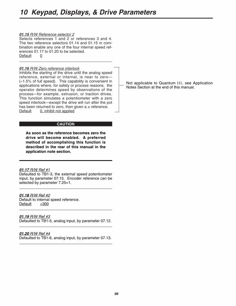
01.15 R/W Reference selector 2Selects references 1 and 2 or references 3 and 4.The two reference selectors 01.14 and 01.15 in com-bination enable any one of the four internal speed ref-erences 01.17 to 01.20 to be selected.Default 0
01.16 R/W Zero reference interlockInhibits the starting of the drive until the analog speedreference, external or internal, is near to zero—(≈1.5% of full speed). This capability is convenient inapplications where, for safety or process reasons, theoperator determines speed by observations of theprocess—for example, extrusion, or traction drives.This function simulates a potentiometer with a zerospeed interlock—except the drive will run after the pothas been returned to zero, then given a ± reference.Default 0, inhibit not applied
CAUTION
As soon as the reference becomes zero thedrive will become enabled. A preferredmethod of accomplishing this function isdescribed in the rear of this manual in theapplication note section.
01.17 R/W Ref #1Defaulted to TB1-3, the external speed potentiometerinput, by parameter 07.15. Encoder reference can beselected by parameter 7.25=1.
01.18 R/W Ref #2Default to internal speed reference. Default +300
01.19 R/W Ref #3Defaulted to TB1-5, analog input, by parameter 07.12.
01.20 R/W Ref #4Defaulted to TB1-6, analog input, by parameter 07.13.
Not applicable to Quantum III, see ApplicationNotes Section at the end of this manual.
10 Keypad, Displays, & Drive Parameters
99
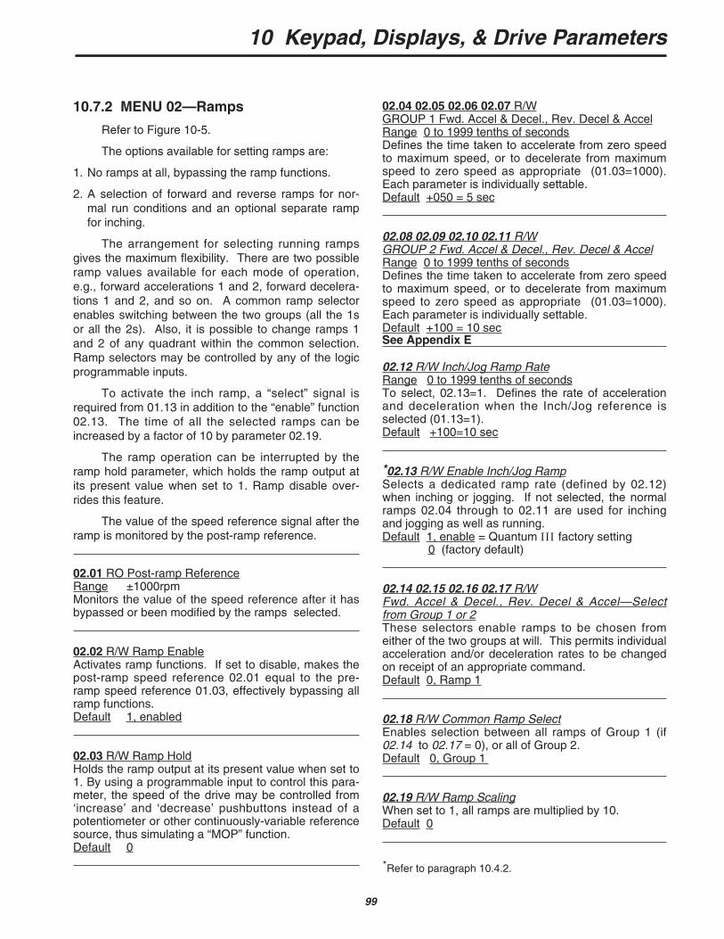
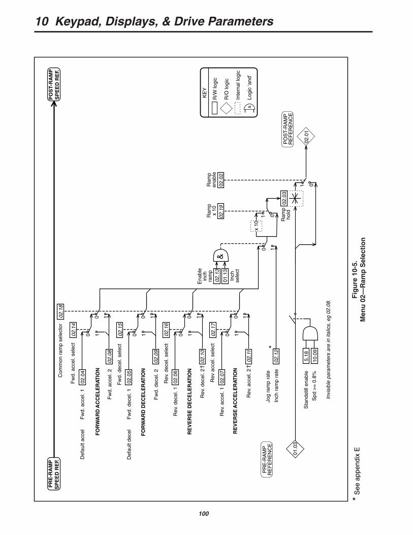
10.7.2 MENU 02—Ramps
Refer to Figure 10-5.
The options available for setting ramps are:
1. No ramps at all, bypassing the ramp functions.
2. A selection of forward and reverse ramps for nor-mal run conditions and an optional separate rampfor inching.
The arrangement for selecting running rampsgives the maximum flexibility. There are two possibleramp values available for each mode of operation,e.g., forward accelerations 1 and 2, forward decelera-tions 1 and 2, and so on. A common ramp selectorenables switching between the two groups (all the 1sor all the 2s). Also, it is possible to change ramps 1and 2 of any quadrant within the common selection.Ramp selectors may be controlled by any of the logicprogrammable inputs.
To activate the inch ramp, a “select” signal isrequired from 01.13 in addition to the “enable” function02.13. The time of all the selected ramps can beincreased by a factor of 10 by parameter 02.19.
The ramp operation can be interrupted by theramp hold parameter, which holds the ramp output atits present value when set to 1. Ramp disable over-rides this feature.
The value of the speed reference signal after theramp is monitored by the post-ramp reference.
02.01 RO Post-ramp ReferenceRange ±1000rpmMonitors the value of the speed reference after it hasbypassed or been modified by the ramps selected.
02.02 R/W Ramp EnableActivates ramp functions. If set to disable, makes thepost-ramp speed reference 02.01 equal to the pre-ramp speed reference 01.03, effectively bypassing allramp functions.Default 1, enabled
02.03 R/W Ramp HoldHolds the ramp output at its present value when set to1. By using a programmable input to control this para-meter, the speed of the drive may be controlled from‘increase’ and ‘decrease’ pushbuttons instead of apotentiometer or other continuously-variable referencesource, thus simulating a “MOP” function.Default 0
02.04 02.05 02.06 02.07 R/WGROUP 1 Fwd. Accel & Decel., Rev. Decel & AccelRange 0 to 1999 tenths of secondsDefines the time taken to accelerate from zero speedto maximum speed, or to decelerate from maximumspeed to zero speed as appropriate (01.03=1000).Each parameter is individually settable.Default +050 = 5 sec
02.08 02.09 02.10 02.11 R/WGROUP 2 Fwd. Accel & Decel., Rev. Decel & AccelRange 0 to 1999 tenths of secondsDefines the time taken to accelerate from zero speedto maximum speed, or to decelerate from maximumspeed to zero speed as appropriate (01.03=1000).Each parameter is individually settable.Default +100 = 10 sec
02.12 R/W Inch/Jog Ramp RateRange 0 to 1999 tenths of secondsTo select, 02.13=1. Defines the rate of accelerationand deceleration when the Inch/Jog reference isselected (01.13=1).Default +100=10 sec
*02.13 R/W Enable Inch/Jog RampSelects a dedicated ramp rate (defined by 02.12)when inching or jogging. If not selected, the normalramps 02.04 through to 02.11 are used for inchingand jogging as well as running.Default 1, enable = Quantum III factory setting
0 (factory default)
02.14 02.15 02.16 02.17 R/WFwd. Accel & Decel., Rev. Decel & Accel—Selectfrom Group 1 or 2These selectors enable ramps to be chosen fromeither of the two groups at will. This permits individualacceleration and/or deceleration rates to be changedon receipt of an appropriate command.Default 0, Ramp 1
02.18 R/W Common Ramp SelectEnables selection between all ramps of Group 1 (if02.14 to 02.17 = 0), or all of Group 2.Default 0, Group 1
02.19 R/W Ramp ScalingWhen set to 1, all ramps are multiplied by 10.Default 0
*Refer to paragraph 10.4.2.
See Appendix E
10 Keypad, Displays, & Drive Parameters
100
Fig
ure
10-
5.M
enu
02—
Ram
p S
elec
tio
n
02.0
4
10
02.0
810
02.0
5
10
02.0
910
02.0
6
10
02.1
010
02.0
7
10
02.1
110
02.1
4
02.1
8
02.1
210
02.0
3
0102
.01
02.0
2
02.1
5
02.1
6
02.1
7
Com
mon
ram
p se
lect
or
Fw
d. a
ccel
. 2
Rev
. acc
el. 2
Fw
d. d
ecel
. 2
Rev
. dec
el. 2
Def
ault
acce
l
Fw
d. a
ccel
. 1
Rev
. acc
el. 1
Def
ault
dece
l
Fw
d. d
ecel
. 1
Rev
. dec
el. 1
† †
Inch
ram
p ra
te
Ena
ble
inch
ram
p
Inch
sele
ct
Ram
pen
able
Fw
d. a
ccel
. sel
ect
Fw
d. d
ecel
. sel
ect
Rev
. dec
el. s
elec
t
Rev
acc
el. s
elec
t
&02
.13
01.1
3
FO
RW
AR
D A
CC
EL
ER
ATIO
N
RE
VE
RS
E A
CC
EL
ER
ATIO
N
RE
VE
RS
E D
EC
EL
ER
ATIO
N
FO
RW
AR
D D
EC
EL
ER
ATIO
N
PR
E-R
AM
PS
PE
ED
RE
F.P
OS
T-R
AM
PS
PE
ED
RE
F.
R/W
logi
c
R/O
logi
c
Inte
rnal
logi
c
Logi
c ‘a
nd’
KE
Y
&
PO
ST-
RA
MP
RE
FE
RE
NC
E
PR
E-R
AM
PR
EF
ER
EN
CE
Invi
sibl
e pa
ram
eter
s ar
e in
ital
ics,
eg
02.0
8.
01x
10
Ram
pho
ld
02.1
9
Ram
px
10
*Jo
g ra
mp
rate
Sta
ndst
ill e
nabl
e
Spd
>=
0.8
%
5.18
10.0
9
01.0
3
*S
ee a
ppen
dix
E
10 Keypad, Displays, & Drive Parameters
101
10.7.3 MENU 03 — Feedback Selection and Speed Loop
Refer to Figure 10-6.
The primary inputs are the post-ramp reference02.01 and the hard speed reference (03.18). Finalspeed demand (03.01) can be either of these inputs ora summation of both. The selected input can be modi-fied by the addition of an offset, which may be zero.The result of this summation is the final speeddemand (03.01) which is added algebraically to thespeed feedback to become the speed error(03.06). The speed error is finally proportioned by thePID function to become the speed loop output (03.07).
Speed feedback is derived from one of threepossible sources— encoder, tachometer, or armaturevoltage. Whichever source is selected becomes thespeed feedback (03.02). The selection is controlledby 03.12 and 03.13. The value is used for the closed-loop speed control of the motor. Scaling of theencoder signal is set by 03.14, and of the armaturevoltage feedback is controlled by the setting of maxi-mum armature voltage 03.15. A potentiometer is pro-vided for scaling the tachometer feedback signal. Thespeed feedback 03.02 is summed with the final speeddemand 03.01 at the speed loop summation point. Ifthe armature voltage is selected, it is first summedwith the IR compensation (03.05) which is derivedfrom the integral function of the speed error and the IRcompensation factor. It is then either added to or sub-tracted from the scaled armature voltage feedbackaccording to whether IR compensation or IR droop isselected.
The armature voltage feedback is passed to acomparator to provide a voltage clamp, used internallyto prevent armature overvoltage. This clamp is usedonly if the armature voltage has NOT been selectedas the feedback. Parameter 03.15 becomes theclamp level.
The speed feedback value is used for two furtherpurposes — to supply a speed indication in rpm, andto indicate zero speed.
03.01 RO Final Speed DemandRange ±1000Monitors the value of the speed reference after it hasbypassed or been modified by the ramps and/or bythe hard speed reference (03.18) and speed offsetfine (03.22). It is the speed reference which is sent tothe speed loop summation point.
03.02 RO Speed FeedbackRange ±1000Monitors the value of the speed feedback, derivedfrom one of the following three sources — encoder,tachometer, or armature voltage. The selection offeedback is controlled by 03.12 and 03.13.
03.03 RO Displayed Speed FeedbackRange ±1999rpmScaled value of motor speed feedback for externalinformation. Requires correct setting of 03.16, maxi-mum speed scaler.
03.04 RO Armature VoltageRange ±1000 (direct reading in Volts)Monitors the value of armature volts.
03.05 RO IR Compensation OutputRange ±1000The result of selected value of IR compensation(03.17) acting on the speed loop integral output.
03.06 RO Speed ErrorRange ±1000The result of the summation of the final speeddemand and the speed feedback, after filtering.
03.07 RO Speed Loop OutputRange ±1000Speed demand forward to become current demand(menu 04).
03.08 RO Speed Error IntegralRange ±1000The integrated value of the speed error 03.06. Usedas input to the IR compensation calculation whenusing armature voltage feedback (AVF).
10 Keypad, Displays, & Drive Parameters
102
03.09 R/W Speed Loop Proportional GainRange 0 to 255The factor by which the speed error is multiplied toproduce the correction term.
Factor = value of 03.098
Increasing this value increases both the system damp-ing and the transient speed response, and if made toohigh for a given load the system will become unstable.The optimum setting is the highest value possiblebefore instability starts to occur. Optimum speed loopperformance is achieved by judicious combination ofall three gains of the PID algorithm.Default 080
03.10 R/W Speed Loop Integral GainRange 0 to 255The factor by which the speed error is multiplied toproduce the correction term.
Factor =6f x (03.10)
256
where f = supply frequency
This term ensures zero speed error during steadystate load conditions Increasing the value increasesthe rate of recovery after a disturbance. If the term ismade too high, speed tends to oscillate instead of set-tling quickly. The optimum setting is the highest valuepossible before oscillation starts to occur. Optimumspeed loop performance is achieved by judicious com-bination of all three gains of the PID algorithm.Default 040
03.11 R/W Speed Loop Derivative GainRange 0 to 255The factor by which the speed error is multiplied toproduce the correction term. There are three possiblesources of input to this term—either final speeddemand 03.01, speed feedback 03.02, or speed error03.06. The selector is 03.24. The derivative term is afunction of the rate of change of value of the input.
If the input is the speed error 03.06, output is negativeif speed error is increasing. This has a dampingeffect.
If the input is the final speed demand 03.01, output ispositive when the final speed demand is increasing.This is called "velocity feed forward”.
If the input is the speed feedback 03.02, output is neg-ative if speed feedback is increasing. This also has adamping effect, but dependent on the changing valueof the speed feedback only,not the speed reference.Default 0
03.12 R/W Digital feedback selectorSet to 1 to select encoder feedback. Set to 0 to selectanalog feedback.Default 0, analog feedback selected
*03.13 R/W Armature Voltage / External AnalogFeedback SelectorDetermines the type of analog speed feedback when03.12 is set to 0. Set to 1 to select armature voltagefeedback. Default setting selects analog feedbackfrom a tachometer or equivalent external source con-nected to terminal TB1-09.Default 1, AVF selected = factory setting
0 (drive default)
03.14 R/W Encoder Feedback ScalingRange 0 to 1999The value should be set to correspond with the maxi-mum speed of the motor and with the number oflines-per-revolution of the encoder. To calculate thescale factor —
Scale factor = 750 x 106N x n
where N = number of lines-per-revolu-tion (encoder)
and n = max speed of motor in rpm.The default value is determined on the basis of a1024-l ine encoder, and a maximum speed of1750rpm.Default + 419
*03.15 R/W Maximum Armature VoltsRange 0 to 1000Defines the maximum voltage permitted to be appliedto the armature. When armature voltage is the select-ed feedback (03.12 = 0 and 03.13 = 1), the max.armature voltage value is used for scaling the arma-ture voltage measurement so that speed feedback isfull scale at maximum voltage. An automatic scalefactor of 1.2 is applied to clamp the armature voltagefeedback to 20% above maximum to allow for over-shoot.
If the speed feedback is derived from an encoder ortachometer, the armature voltage is continuouslymonitored, and a clamp is applied when the voltageexceeds that set in 03.15. This can be used to pre-vent the voltage rising above a set level.
Default +500 = Quantum III factory setting+600 (drive default)
*Refer to paragraph 10.4.2.

10 Keypad, Displays, & Drive Parameters
103
03.16 R/W Speed Readout Scaler
Range 0 to 1999Used only to scale the speed feedback so that thevalue displayed in 03.03 is actual speed in rpm. Thevalue applied to 03.16 should be the max. speed inrpm (divided by ten if the maximum speed is>1999rpm); speed displayed in 03.03 is then rpm / 10.This does not affect motor speed.
If desired 3.03 could be scaled to readout machinespeeds. Example: At 100% motor speed machine putsout 250 bottles/min. Place 250 into #3.16.
Default + 1750
03.17 R/W IR CompensationRange 0 to 255
Value of 03.05 = (03.08) x (03.17)2048
This value is used to calculate the compensationneeded for the resistive voltage-drop of the armatureto improve speed control with varying loads when theselected speed feedback is the armature voltage.
IR compensation is a positive feedback, and may giverise to instability if set too high. Furthermore, modernlaminated-frame motors have typically a rising load-speed characteristic unsuited to armature voltagefeedback with IR compensation. IR compensation ismore suited to compound-wound motors with a flat(not rising) load-speed characteristic.
The integral of the speed error is used as the input toIR compensation rather than current feedbackbecause it has the least amount of ripple of the vari-ables; in speed control, the value of the speed errorintegral is the steady-state value of current demand.Default 000
03.18 R/W Hard Speed ReferenceRange ±1000Speed reference fed into the speed loop without pass-ing through the ramps.Default (07.11)
03.19 R/W Hard Speed Reference SelectorIf 03.19 is set to 1, and Ref “ON” (01.11) =1, the HardSpeed reference (3.18) is added at the speed loopsummation point. For hard reference only, 03.21 must= 0.Default 0
03.20 R/W IR Droop SelectorIf 03.20=1 when using armature voltage as the speedfeedback, speed will decrease as load increases.A typical application, for example, is a mechanicalblanking press with a heavy flywheel. Applying IRdroop prevents the drive from delivering a suddenincrease of current at the moment of impact (suddenincrease of torque demand). It is better that thedrive deliver energy to the flywheel during the wholeoperating cycle rather than mostly at the moment ofimpact.Default 0
03.21 R/W Ramp Output SelectorWhen 03.21=1, Ramp output is added at the speedloop summation point.Default 1
03.22 R/W Speed Offset Fine
Range 0 to 255Used as a fine trim on the speed reference signal tocorrect, or introduce, a small offset. 0 = maximum negative offset256 = maximum positive offset Default 128
03.23 R/W Zero Speed Threshold
Range 0 to 255The threshold may be adjusted to any value up to25.5% of maximum speed. Refer also to 10.09.Default 16
03.24 R/W Derivative Term Source
Range 1,2, or 3The derivative term of the PID in the speed loop mayuse one of three sources—
1=Speed error of 03.06Damping changes in speed demand and feedback
2=Speed reference 03.01Velocity feed forward
3=Speed feedback 03.02Damping on feedback only (“feedback forcing”).
Default 1
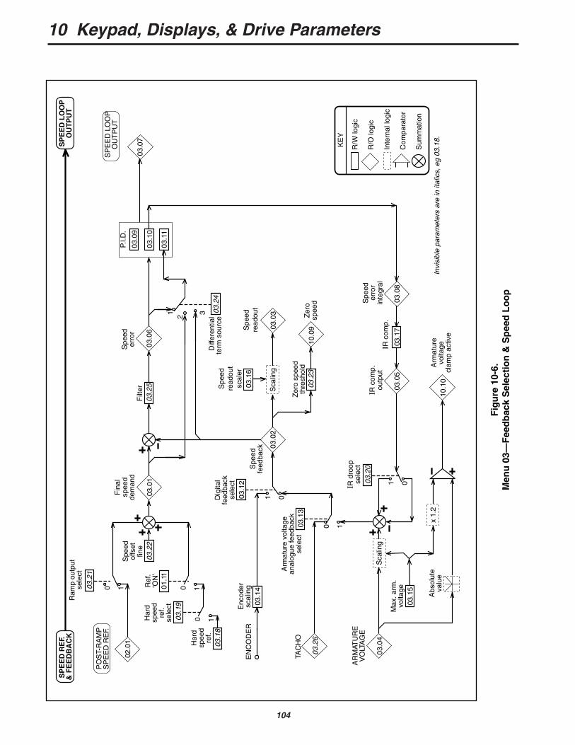
10 Keypad, Displays, & Drive Parameters
104
03.1
5
02.0
11003
.21
PO
ST-
RA
MP
SP
EE
D R
EF.
03.1
81003
.19
1001.1
1
Ref
. ‘O
N’
Har
d sp
eed
ref.
sele
ct
Ram
p ou
tput
se
lect
03.2
2
Spe
ed
offs
et
fine
03.0
1
03.0
4S
calin
g
Max
. arm
.vo
ltage
AR
MAT
UR
EV
OLT
AG
E
EN
CO
DE
R
TAC
HO
03.2
6
03.1
4
Enc
oder
scal
ing
1003.1
3
Arm
atur
e vo
ltage
anal
ogue
feed
back
se
lect
1 003.1
2
Dig
ital
feed
back
se
lect
03.0
2
1 003
.05
03.1
703
.08
Fin
alsp
eed
dem
and
Spe
edfe
edba
ck
Spe
eder
ror
inte
gral
03.2
0
IR d
roop
sele
ct
10.1
0A
rmat
ure
volta
gecl
amp
activ
e
Sca
ling
03.1
6
03.2
3
Zer
o sp
eed
thre
shol
d10
.09
Zer
osp
eed
03.0
3
Spe
edre
adou
t
03.2
503
.06
Spe
eder
ror
Filt
er
03.1
1
03.1
0
03.0
9
03.2
4D
iffer
entia
l te
rm s
ourc
e
1 2 3
IR c
omp.
03.0
7
SP
EE
D L
OO
PO
UT
PU
T
Har
d sp
eed
ref.
IR c
omp.
outp
ut
Abs
olut
eva
lue
SP
EE
D R
EF.
& F
EE
DB
AC
KS
PE
ED
LO
OP
OU
TP
UT
R/W
logi
c
R/O
logi
c
Inte
rnal
logi
c
Com
para
tor
Sum
mat
ion
KE
Y
P.I.D
.
Invi
sibl
e pa
ram
eter
s ar
e in
ital
ics,
eg
03.1
8.x
1.2
Spe
edre
adou
tsc
aler
Fig
ure
10-
6.M
enu
03—
Fee
db
ack
Sel
ecti
on
& S
pee
d L
oo
p
10 Keypad, Displays, & Drive Parameters
105
03.25 R/W Speed Error Filter
Range 0 to 255
Filter time constant = 2566f x (03.25)
where, f = supply frequency
A low-pass filter to reduce the effect of interference onthe speed error signal (03.04) —from a noisytachometer, for example.Default 128
03.26 RO Tachometer Input
Range ±1000Monitors the tachometer input measurement. Thetachometer potentiometer scales the feedback signalsuch that at full motor speed, 03.26 = 1000. Units dis-played = 0.1% of full speed per increment.
3.27 RO Speed Feedback Range
03.27 = 0 03.16 set up in rpm
03.27 = 1 03.16 is (rpm+10) ie 03.16 = 600 for 600 rpmSimilar to 05.15, this parameter indicates to the option-al LCD pod the speed feedback range in which para-meter 03.16 has been set up.
3.28 R/W Increase P Gain by 4
Range 0 or 1
Setting this parameter at 1 will increase the speedloop proportional gain by a factor of 4. Proportional Gain x 4.Default 0
03.29 R/W Reduce P and I Gain by 8Range 0 or 1
Enables the user to increase the burden resistors by afactor of 1.6. Reduce P and I gain by 8 if set to 1.Default 0
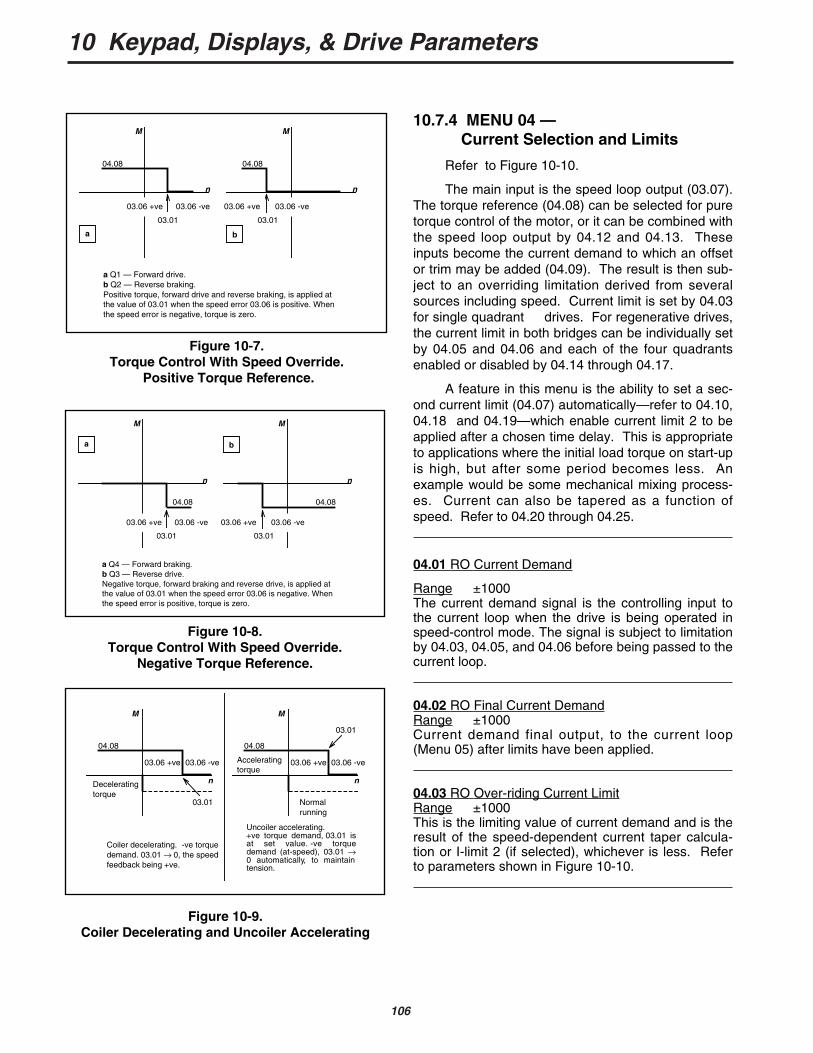
10 Keypad, Displays, & Drive Parameters
106
M
04.08
03.06 +ve
03.01
03.06 -ve
n
M
04.08
03.01
03.06 -ve
n
03.06 +ve
a b
a Q4 — Forward braking.b Q3 — Reverse drive.Negative torque, forward braking and reverse drive, is applied at the value of 03.01 when the speed error 03.06 is negative. When the speed error is positive, torque is zero.
Figure 10-8.Torque Control With Speed Override.
Negative Torque Reference.
10.7.4 MENU 04 — Current Selection and Limits
Refer to Figure 10-10.
The main input is the speed loop output (03.07).The torque reference (04.08) can be selected for puretorque control of the motor, or it can be combined withthe speed loop output by 04.12 and 04.13. Theseinputs become the current demand to which an offsetor trim may be added (04.09). The result is then sub-ject to an overriding limitation derived from severalsources including speed. Current limit is set by 04.03for single quadrant drives. For regenerative drives,the current limit in both bridges can be individually setby 04.05 and 04.06 and each of the four quadrantsenabled or disabled by 04.14 through 04.17.
A feature in this menu is the ability to set a sec-ond current limit (04.07) automatically—refer to 04.10,04.18 and 04.19—which enable current limit 2 to beapplied after a chosen time delay. This is appropriateto applications where the initial load torque on start-upis high, but after some period becomes less. Anexample would be some mechanical mixing process-es. Current can also be tapered as a function ofspeed. Refer to 04.20 through 04.25.
04.01 RO Current Demand
Range ±1000The current demand signal is the controlling input tothe current loop when the drive is being operated inspeed-control mode. The signal is subject to limitationby 04.03, 04.05, and 04.06 before being passed to thecurrent loop.
04.02 RO Final Current DemandRange ±1000Current demand final output, to the current loop(Menu 05) after limits have been applied.
04.03 RO Over-riding Current LimitRange ±1000This is the limiting value of current demand and is theresult of the speed-dependent current taper calcula-tion or I-limit 2 (if selected), whichever is less. Referto parameters shown in Figure 10-10.
Figure 10-9.Coiler Decelerating and Uncoiler Accelerating
M
04.08
03.01
03.06 -ve
n
03.06 +ve
Decelerating torque
Accelerating torque
Coiler decelerating. -ve torque demand. 03.01 → 0, the speed feedback being +ve.
Uncoiler accelerating. +ve torque demand, 03.01 is at set value. -ve torque demand (at-speed), 03.01 → 0 automatically, to maintain tension.
M
04.08
03.01
03.06 -ve
n
03.06 +ve
Normalrunning
Figure 10-7.Torque Control With Speed Override.
Positive Torque Reference.
M
04.08
03.06 +ve
03.01
a Q1 — Forward drive.b Q2 — Reverse braking.Positive torque, forward drive and reverse braking, is applied at the value of 03.01 when the speed error 03.06 is positive. When the speed error is negative, torque is zero.
03.06 -ve
n
M
04.08
03.01
03.06 -ve
n
03.06 +ve
a b
10 Keypad, Displays, & Drive Parameters
107
04.04 R/W Current-limit 1 (taper start point)Range 0 to 1000 = 150% of drive ratingThis parameter provides symmetrical current-limitationfor bridges 1 and 2 and is the level from which the cur-rent taper functions operate—refer to 04.20 and04.21. I-limit 1 can be used in applications where themotor kW rating is somewhat less than that of thedrive, as an alternative to changing the fixed current-burden resistors. Default +1000
04.05 R/W Current-limit Bridge 1Range 0 to 1000Determines the maximum limit of current demandwhen bridge 1, the ‘positive’ bridge, is conducting. Itcauses any demand for current in excess of the limitset point to be clamped.Default +1000 = 150% of drive rating
04.06 R/W Current-limit Bridge 2Range 0 to 1000Determines the maximum limit of current demandwhen bridge 2, the ‘negative’ bridge, is conducting. Itcauses any demand for current in excess of the limitset point to be clamped.Default +1000 = 150% of drive rating
04.07 R/W Current-limit 2Range 0 to 1000Available as an additional current limit. Applies toboth bridges. The drive can be programmed, ifdesired, to select 04.05 automatically at a pro-grammed time interval after a RUN signal. Refer to04.10, 04.18 and 04.19.Default +1000 = 150% of drive rating
04.08 R/W Torque ReferenceRange ±1000This value is an input to the current loop and can beselected for use in applications requiring direct controlof current (motor torque).Default +000
04.09 R/W Current OffsetRange ±1000Current offset is used to apply a trim to the currentdemand 04.01.Default +000
04.10 R/W Current -limit 2 SelectorSet 04.10 = 1 to select I-limit 2, or can be pro-grammed to change automatically—refer to 04.18 and04.19.Default 004.11 R/W Current Offset SelectorSelects the value in 04.09 as a current offset.Default 0
04.12 R/W Mode bit 0Operates in conjunction with 04.13 to configure thedrive for speed control or any of three modes oftorque control. Refer to 04.13 .Default 0, not selected
04.13 R/W Mode bit 1Operates in conjunction with 04.12 to configure thedrive for speed control or any of three modes oftorque control, as follows—
04.12 = 0 and 04.13 = 0 Speed mode control (normal configuration)
04.12 = 1 and 04.13 = 0 Basic current- or torque-control mode.
In this mode, the torque reference 04.08 is the inputto the current loop and is subject to the limitations ofthe over-riding current limit 04.03, the Bridge 1 andBridge 2 limits 04.05 and 04.06, and to the currentslew rate 05.04.
04.12 = 0 and 04.13 = 1 Torque-control mode with speed override. Refer to Figures 10-7 and 10-8.
In this mode, the output of the speed loop is clampedeither to the value of the torque reference 04.08 , or to0—depending on whether the speed error 03.06 ispositive or negative, and on whether the torque refer-ence is positive or negative, i.e., dependent on rela-tive polarities.
In the two motoring quadrants, speed is limited to thevalue of the final speed demand 03.01, preventinguncontrolled increase of speed when load is removed.The drive should be adjusted to run at a slight over-speed when off load to insure adequate currentdemand at all speeds.
In the two regenerative quadrants, the currentdemand set by torque reference 04.08 is disabledwhen speed is less than that set by the final speeddemand 03.01. This prevents the reducing loadtorque resulting in reversal of rotation. The 03.01value should be 0.

10 Keypad, Displays, & Drive Parameters
108
Fig
ure
10-
10.
Men
u 0
4—C
urr
ent
Sel
ecti
on
& L
imit
s
Ove
r-rid
ing
curr
ent l
imit
03.0
7
SP
EE
DF
EE
DB
AC
K
03.0
2
04.0
2
04.0
3
04.0
1
04.1
1
04.0
9
I-lim
it 1
I-lim
it 2
Sel
ect I
-lim
it 2
Ena
ble
auto
I-li
mit
chan
geI-
limit
timer
Tape
r 1
slop
eTa
per
2 sl
ope
04.1
204
.13
04.1
404
.15
04.1
604
.17
Mod
e bi
t 0M
ode
bit 1
Qua
dran
t 1 e
nabl
eQ
uadr
ant 2
ena
ble
Qua
dran
t 3 e
nabl
eQ
uadr
ant 4
ena
ble
Cur
rent
dem
and
Ext
erna
lT
orqu
eR
efer
ence
0 1
Offs
etse
lect
Cur
rent
offs
et
Thr
esho
ld 1
exce
eded
04.2
4
Thr
esho
ld 2
exce
eded
04.2
5
04.0
404
.07
04.1
004
.18
04.2
204
.23
04.1
9
I-lim
it B
1I-
limit
B2
04.0
504
.06
Tape
r 1
thre
shol
d04
.20
Tape
r 2
thre
shol
d04
.21
SP
EE
D L
OO
PO
UT
PU
TR
/W lo
gic
R/O
logi
c
Inte
rnal
logi
c
Sum
mat
ion
Lim
its
KE
Y
SP
EE
D L
OO
PO
UT
PU
TF
INA
L C
UR
RE
NT
DE
MA
ND
FIN
AL
CU
RR
EN
TD
EM
AN
D
04.0
8
Invi
sibl
e pa
ram
eter
s ar
e in
ital
ics,
eg
04.0
7.
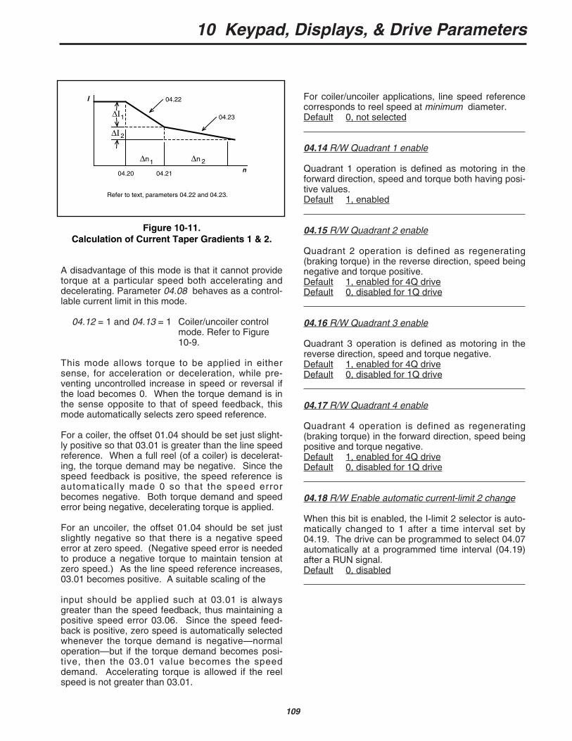
10 Keypad, Displays, & Drive Parameters
109
A disadvantage of this mode is that it cannot providetorque at a particular speed both accelerating anddecelerating. Parameter 04.08 behaves as a control-lable current limit in this mode.
04.12 = 1 and 04.13 = 1 Coiler/uncoiler control mode. Refer to Figure10-9.
This mode allows torque to be applied in eithersense, for acceleration or deceleration, while pre-venting uncontrolled increase in speed or reversal ifthe load becomes 0. When the torque demand is inthe sense opposite to that of speed feedback, thismode automatically selects zero speed reference.
For a coiler, the offset 01.04 should be set just slight-ly positive so that 03.01 is greater than the line speedreference. When a full reel (of a coiler) is decelerat-ing, the torque demand may be negative. Since thespeed feedback is positive, the speed reference isautomatically made 0 so that the speed errorbecomes negative. Both torque demand and speederror being negative, decelerating torque is applied.
For an uncoiler, the offset 01.04 should be set justslightly negative so that there is a negative speederror at zero speed. (Negative speed error is neededto produce a negative torque to maintain tension atzero speed.) As the line speed reference increases,03.01 becomes positive. A suitable scaling of the
input should be applied such at 03.01 is alwaysgreater than the speed feedback, thus maintaining apositive speed error 03.06. Since the speed feed-back is positive, zero speed is automatically selectedwhenever the torque demand is negative—normaloperation—but if the torque demand becomes posi-tive, then the 03.01 value becomes the speeddemand. Accelerating torque is allowed if the reelspeed is not greater than 03.01.
For coiler/uncoiler applications, line speed referencecorresponds to reel speed at minimum diameter.Default 0, not selected
04.14 R/W Quadrant 1 enable
Quadrant 1 operation is defined as motoring in theforward direction, speed and torque both having posi-tive values.Default 1, enabled
04.15 R/W Quadrant 2 enable
Quadrant 2 operation is defined as regenerating(braking torque) in the reverse direction, speed beingnegative and torque positive.Default 1, enabled for 4Q driveDefault 0, disabled for 1Q drive
04.16 R/W Quadrant 3 enable
Quadrant 3 operation is defined as motoring in thereverse direction, speed and torque negative.Default 1, enabled for 4Q driveDefault 0, disabled for 1Q drive
04.17 R/W Quadrant 4 enable
Quadrant 4 operation is defined as regenerating(braking torque) in the forward direction, speed beingpositive and torque negative.Default 1, enabled for 4Q driveDefault 0, disabled for 1Q drive
04.18 R/W Enable automatic current-limit 2 change
When this bit is enabled, the I-limit 2 selector is auto-matically changed to 1 after a time interval set by04.19. The drive can be programmed to select 04.07automatically at a programmed time interval (04.19)after a RUN signal.Default 0, disabled
Figure 10-11.Calculation of Current Taper Gradients 1 & 2.
I
n04.20 04.21
04.22
04.23
23 Calculation of current taper gradients 1 & 2.Refer to text, parameters 04.22 and 04.23.
∆I1
∆n1 2∆n
2∆I

10 Keypad, Displays, & Drive Parameters
110
04.23 R/W Current taper 2 slopeRange 0 to 255Sets the rate of change of armature I-limit withrespect to speed in either direction of rotation, abovethe threshold set by 04.21.
Scaling factor (refer to Figure 10-11):
04.23 = 128 X ∆I2∆n2
Default 000
04.24 RO Taper threshold 1 exceededSet to 1 when the threshold set point of 04.20 isexceeded.
04.25 RO Taper threshold 2 exceededSet to 1 when the threshold set point of 04.21 isexceeded.
04.19 R/W Current -limit timerRange 0 to 255A time interval up to 255 seconds can be pro-grammed. If 04.18=1, I-limit 2 is automatically select-ed when the set time elapses after a RUN command.This feature is appropriate to applications WHERETHE MOTOR IS SHORT-TIME RATED, such as mix-ing machinery, where the starting load is high andfalls to a lower, constant value only after the machinehas run for some time.Default 000
04.20 R/W Current taper 1 thresholdRange 0 to 1000Sets a threshold value of speed feedback, beyondwhich 04.24 changes to 1 to indicate that the thresh-old has been exceeded, and is the starting point fortaper 1 (if implemented). Armature current reduces,as a function of speed, at a rate defined by 04.22.This parameter can also be used as a general pur-pose speed threshold.If only one taper is used, it must be taper 1. If bothare used, taper 1 must be the first.Default +1000
04.21 R/W Current taper 2 thresholdRange 0 to 1000Sets a threshold value of speed feedback, beyondwhich 04.25 changes to 1 to indicate that the thresh-old has been exceeded, and is the starting point fortaper 2 (if implemented). Armature current reduces,as a function of speed, at a rate defined by 04.23.This parameter can also be used as a general pur-pose speed threshold.Default +1000
04.22 R/W Current taper 1 slopeRange 0 to 255Sets the rate of change of armature I-limit withrespect to speed in either direction of rotation, abovethe threshold set by 04.20.
Scaling factor (refer to Figure 10-11):
04.22 = 128 X ∆I1∆n1
Default 000
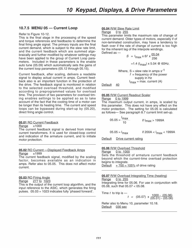
10 Keypad, Displays, & Drive Parameters
111
05.04 R/W Slew Rate LimitRange 0 to 255This parameter limits the maximum rate of change ofcurrent demand. Older types of motors, especially if ofnon-laminated construction, may have a tendency toflash over if the rate of change of current is too highfor the inherent lag of the interpole windings.Defined as —
S = Imax x 6f x 05.04256
=1.4 (Imax) x 5.04 @ 60Hz.
Where, S = slew rate in amps s-1f = frequency of the power
supply in HzImax = max. current (A)
Default 40
05.05 R/W Current Readout ScalerRange 0 to 1999The maximum output current, in amps, is scaled bythis parameter. This does not have any effect on themotor protection. The setting for 05.05 is calculatedas follows— See paragraph 8.7 current limit set-up.
05.05 =Imax
if Imax > 1999A10
05.05 = Imax if 200A < Imax < 1999A
Default Drive current rating
05.06 R/W Overload ThresholdRange 0 to 1000Sets the threshold of armature current feedbackbeyond which the current-time overload protectionbegins to integrate.Default + 700 = 105% of drive rating
05.07 R/W Overload Integrating Time (heating)Range 0 to 255Integrating time for 05.06. For use in conjunction with05.08, such that 05.07 < 05.08.
Time t to trip is —t = (05.07) x 1000 - (05.06)
(05.01) - (05.06)
Refer also to Menu 10, parameter 10.18.Default 030 sec
10.7.5 MENU 05 — Current Loop
Refer to Figure 10-12.This is the final stage in the processing of the speedand torque references and feedbacks to determine thefinal firing angle signal. The primary inputs are the finalcurrent demand, which is subject to the slew rate limit,and the current feedback which are summed alge-braically and further modified by whatever settings mayhave been applied to the group of Current Loop para-meters. Included in these parameters is the enableauto tune (05.09) which automatically sets the gains ofthe current loop parameters (05.12 through 05.15).
Current feedback, after scaling, delivers a readablesignal to display actual current in amps. Current feed-back also is an important function in the protection ofthe drive. The feedback signal is monitored in relationto the selected overload threshold, and modifiedaccording to preprogrammed values for overloadtime. The provision of two parameters for overload tim-ing enables settings to be applied so as to takeaccount of the fact that the cooling time of a motor canbe longer than its heating time. The current and speedloops can be bypassed during start-up by (05.20),direct firing angle control.
05.01 RO Current FeedbackRange ±1000The current feedback signal is derived from internalcurrent transformers. It is used for closed-loop controland indication of the armature current, and to initiatemotor protection.
05.02 RO Current —Displayed Feedback AmpsRange ±1999The current feedback signal, modified by the scalingfactor, becomes available as an indication inamps. Refer also to 05.05. This does not affect motorcurrent.
05.03 RO Firing AngleRange 277 to 1023This is the output of the current loop algorithm, and theinput reference to the ASIC, which generates the firingpulses. 05.03 = 1023 indicates fully ‘phased forward’.
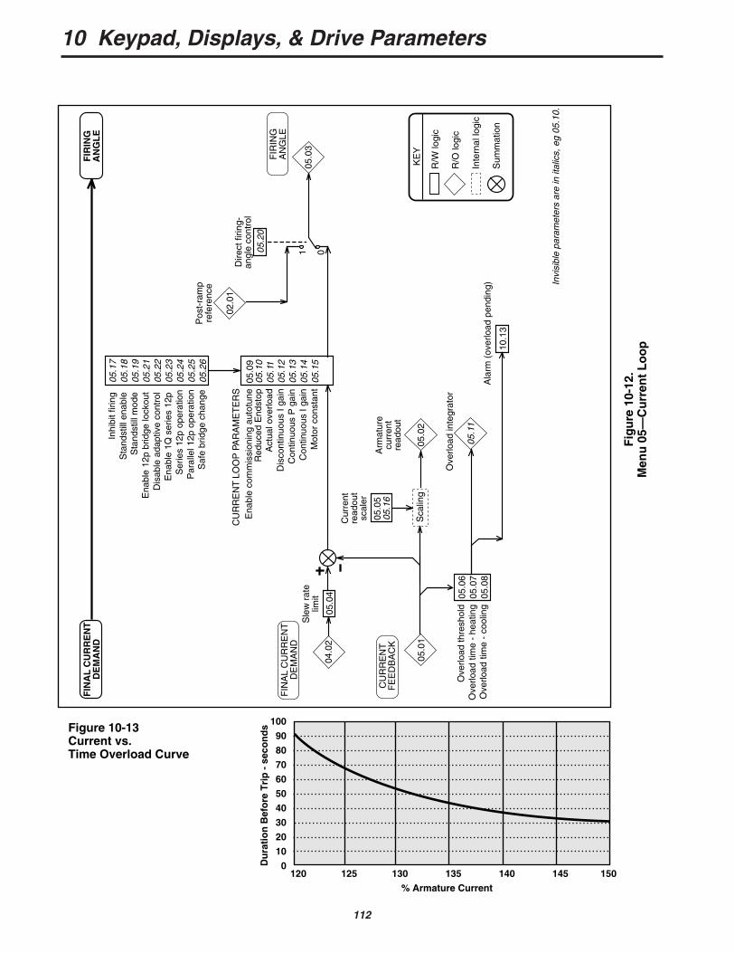
10 Keypad, Displays, & Drive Parameters
112
05.1
705
.18
05.1
905
.21
05.2
205
.23
05.2
405
.25
05.2
6
Inhi
bit f
iring
Sta
ndst
ill e
nabl
eS
tand
still
mod
eE
nabl
e 12
p br
idge
lock
out
Dis
able
ada
ptiv
e co
ntro
lE
nabl
e 1Q
ser
ies
12p
Ser
ies
12p
oper
atio
nP
aral
lel 1
2p o
pera
tion
Saf
e br
idge
cha
nge
Ena
ble
com
mis
sion
ing
auto
tune
Red
uced
End
stop
Act
ual o
verlo
adD
isco
ntin
uous
I ga
inC
ontin
uous
P g
ain
Con
tinuo
us I
gain
Mot
or c
onst
ant
05.0
905
.10
05.1
105
.12
05.1
305
.14
05.1
5
CU
RR
EN
T LO
OP
PA
RA
ME
TE
RS
05.0
605
.07
05.0
8
Ove
rload
thre
shol
dO
verlo
ad ti
me
- he
atin
gO
verlo
ad ti
me
- co
olin
g
05.0
1
10.1
3
04.0
2
05.0
2
05.0
3
05.1
1
FIN
AL
CU
RR
EN
T D
EM
AN
D
CU
RR
EN
T F
EE
DB
AC
K
FIR
ING
A
NG
LE
Sca
ling
Arm
atur
ecu
rren
tre
adou
t
05.0
4
Sle
w r
ate
limit
1 005.2
0
02.0
1
Pos
t-ra
mp
refe
renc
e
Dire
ct fi
ring-
angl
e co
ntro
l
05.0
505
.16
Cur
rent
read
out
scal
er
Ove
rload
inte
grat
or
Ala
rm (
over
load
pen
ding
)
R/W
logi
c
R/O
logi
c
Inte
rnal
logi
c
Sum
mat
ion
KE
Y
FIR
ING
AN
GL
EF
INA
L C
UR
RE
NT
DE
MA
ND
Invi
sibl
e pa
ram
eter
s ar
e in
ital
ics,
eg
05.1
0.
Fig
ure
10-
12.
Men
u 0
5—C
urr
ent
Lo
op
Figure 10-13Current vs. Time Overload Curve
100
90
80
70
60
50
40
30
20
10
0120 125 130 135 140 145 150
Du
rati
on
Bef
ore
Tri
p -
sec
on
ds
% Armature Current
10 Keypad, Displays, & Drive Parameters
113
05.12 R/W Discontinuous I-gainRange 0 to 255Set by the Start-up Autotune parameter 05.09.This parameter is set to correct any errors in the pre-diction of firing angle in the discontinuous currentregion. If 05.15 is set correctly, 05.12 has little effect;but if set too high, instability can occur.
Gain applied = value of 05.12512
Default 65 (ver. < 4.10); 16 (ver. > 4.10)
05.13 R/W Continuous P-gainRange 0 to 255Set by the Start-up Autotune parameter 05.09.This parameter enables the current loop to follow veryclosely a step-change in current. If set too high, therewill be an overshoot. If set too low, the new currentvalue will be achieved very slowly.
Gain applied = value of 05.13512
Default 33 (ver. < 4.10); 16 (ver. > 4.10)
05.14 R/W Continuous I-gainRange 0 to 255Set by the Start-up Autotune parameter 05.09.Its value will depend on the motor time-constant.Increasing the value of 05.14 improves the responseof the current loop, but at the risk of instability.
Gain applied = value of 05.141024
Default 33 (ver. < 4.10); 16 (ver. > 4.10)
05.15 R/W Motor ConstantRange 0 to 255This parameter is used to scale the current demandsuch that the control loop correctly predicts the firingangle in the discontinuous current region. It is setautomatically by the Start-up Autotune parameter05.09.Default 50 (ver. < 4.10); 25 (ver. > 4.10)
05.16 R/W RESERVEDRange 0 to 255Default 0
05.17 R/W Inhibit FiringIf set to 1, disables SCR firing (both bridges), andresets acceleration and deceleration ramps.Default 0, enabled
05.08 R/W Overload Integrating Time (cooling)Range 0 to 255Integrating time for 05.06. For use in conjunction with05.07, such that 05.08 > 05.07.
Time t to trip is —t = (05.08) x 1000 - (05.06)
(05.06) - (05.01)
Refer also to Menu 10, parameter 10.18.Default 050 sec
05.09 R/W Enable AutotuneTo autotune the current loop during start-up—
• Disconnect the field of the motor if a fixed fieldis being used. Models 9500-8X01 through9500-8X06 are standard with field control.This will disconnect the field automatically.Observe approved safety procedures!
• Enable autotune — set 05.09 =1.• Depress Start pushbutton to enable the drive.
When the autotune process is complete, the driveready relay will open for 50ms after which the auto-tune parameter will be automatically set to disable(05.09 = 0). This process allows the autotunesequence to be started when a ‘run permit’ is presentbut returns the drive to a safe condition when theautotune is complete. It may be necessary to clampthe motor shaft if it tends to rotate during this proce-dure.Default 0, disabled
05.10 R/W Reduced EndstopThe endstop allows the armature voltage to rise, dur-ing regeneration, to 1.16 x supply voltage. On very“soft” supplies the endstop may be too close to thecrossover point. Setting 05.10=1 increases the safetymargin but reduces the maximum regenerated arma-ture voltage to 1.05 x supply voltage.Default 0, disabled
05.11 RO Actual overloadRange 0 to 1999Monitors the value of the integrating current-time over-load. When the value reaches the trip point deter-mined by 05.06, 05.07, and 05.08, an overload tripoccurs. The overload trip operates when 05.11 reach-es the value given by:
[1000-05.06] x 1016
The rate at which 05.11 increases or decreases iscontrolled by the values of 05.07 and 05.08, respec-tively.
10 Keypad, Displays, & Drive Parameters
114
*Refer to paragraph 10.4.2.
05.18 R/W Enable Standstill LogicWhen enabled, causes the firing angle to be fullyphased back when the drive has received a STOPcommand and when the speed falls below 0.8% ofmaximum speed. After a short time delay, the SCRsare inhibited also. This prevents “creep” and is usedin applications in which there is no requirement tomaintain motor torque at standstill. Refer also to05.19.Default 1, enable
*05.19 R/W Standstill Mode05.19=0—standstill logic is enabled after STOP
command or zero reference.
05.19=1—standstill logic enabled after STOPcommand only.
Setting 05.19=1 has the effect of not enabling thestandstill logic when the stopping signal is given bythe reference alone. This condition, therefore, allowscreep speeds, shaft orientation, and other functionswhich occur close to zero speed, while preventing any“creep” after a STOP command.Default 1
0 (factory default)
05.20 R/W Enable Direct Firing Angle ControlWhen enabled, the firing angle 05.03 is controlled bythe value of the post-ramp reference 02.01. Thismode is valuable for system diagnosis, particularlywhere instability is present. It allows the drive to oper-ate without the influence of either the speed loop orthe current loop, eliminating their effect upon the sys-tem.Default 0, disabled
CAUTION
This function must be used cautiously.When the reference is 02.01, there is noprotection against excessive acceleration,output voltage or current other than theinstantaneous overcurrent trip. Also, besure to reset 05.20=0 after completion oftests.
05.21 R/W Enable Bridge 2 LockoutRequires to be set only for parallel 12-pulse 4Q sys-tem installations comprising two (2) drives which areto share load, to prevent one drive changing bridgeswhile the other is still conducting.Default 0, disabled
05.22 R/W Disable Adaptive ControlSetting 05.22=1 disables adaptive control.When adaptive control is enabled (default status), thecurrent loop employs two different algorithms, one ofwhich applies high gain in the discontinuous-currentregion. This is unsuitable for some applications, suchas non-motor loads, for which adaptive control shouldbe disabled.Default 0, enabled
05.23 R/W Enable Single-quadrant Series 12-pulseEnabling this function configures the drive to delivernormal and delayed firing pulses to a single 12-chan-nel power board. Cannot be enabled if either of theBridge 2 quadrants 04.16 and 04.17 are enabled.In 6-pulse SCR drives, the current drawn from eachphase of the supply is not continuous. Out of each180° of the AC supply cycle, full load current is drawnfor 120° and none for the remaining 60°. This impos-es a degree of harmonic distortion on the supply.Twelve-pulse SCR drives draw current for the full360° of the AC supply cycle, and the current wave-form approximates very closely to a sine wave, withmuch reduced distortion as a result.A further advantage is the much smoother DC out-put from 12-pulse drives, which is a benefit in manyapplications.Two 12-channel Power Boards are driven by pcbMDA1 for 4Q series 12 pulse.Default 0, disabled
05.24 R/W Series 12-pulse operationThis parameter should be set for operation in eithersingle- or four-quadrant 12-pulse mode. Parameter05.23 (see above) is read by the software only atpower-on and during a cyclic reset. (This is a resetwhen the drive is disabled.) If either of the Bridge 2quadrants is enabled when 05.23 is read, the outputsare not diverted within the ASIC and 05.23 is set to 0.Default 0, disabled
NOTESeries 12-pulse mode is phase-sensitive. Therotation on the SCRs must be in the sequenceL1, L2, L3 (10.11=1).
05.25 R/W Parallel 12-pulse operationThis parameter instructs the drive to operate in paral-lel 12-pulse mode and should be set for operation ineither single- or four-quadrant mode. For 4-quadrantoperation, parameter 05.21 (see above) must be setto 1. The F10 input of each drive must be connectedto the ST5 output of the other. Also, the control 0Vterminals of both drives must be connected.Default 0, disabled
10 Keypad, Displays, & Drive Parameters
115
05.26 R/W Extra-safe Bridge LockoutWhen enabled (=1), parameter 05.26 applies an addi-tional safety margin to the bridge lockout logic. Thismay be required for highly inductive loads, such as amotor field winding.Default 0, disabled
05.27 RWB Continuous autotune (For firmware revi-sions > 4.09.00) When enabled, an additional auto-tune routine continually monitors current duringconduction and adjusts the current loop gains accord-ing to the amount of current ripple measured.Default 0
05.28 RWB Reduce Hysteresis or bridge changeover(For firmware revisions > 4.09.00) Used to reducehysteresis or bridge changeover in applications whenfine control of current is required. When set, reducesthe hysteresis to 0.2% of drive maximum current.Default 0
05.29 R/W Burden Resistor Increase selectionRange 0 or 1
This parameter when set allows the user to increasethe HP scaling (burden) resistors by a factor of 1.6.The software scales the current feedback differently tocompensate for the change in burden values.When parameter #05.29 is set and the burdens havebeen changed, the minimum ripple of 0.6V on terminal11 occurs at a feedback value of 38 in parameter#05.01 or 5.7% of drive rating.Setting parameter #05.29 also changes the range ofparameter #05.15 such that it does not have to be setclose to its maximum value of 255 when continuousconduction occurs at such low currents.Default 0

10 Keypad, Displays, & Drive Parameters
116
Fig
ure
10-
14.
Men
u 0
6—F
ield
Co
ntr
ol
03.0
4
03.0
8
AR
MAT
UR
EV
OLT
AG
E
SP
EE
D
ER
RO
RIN
TE
GR
AL
FIN
AL
CU
RR
EN
TD
EM
AN
D
06.0
6
IR
com
p. 2
06.0
1
Bac
kem
f
06.0
7B
ack-
em
fse
t poi
ntP +
I
06.1
0M
in. f
ield
curr
ent
08.1
106
.14
06.1
206
.15
DR
IVE
EN
AB
LE
Fie
ldec
onom
yE
cono
my
timeo
utE
nabl
e ec
onom
y tim
eout
Max
. fie
ld 2
sele
ct
06.0
8M
ax. f
ield
curr
ent 1
06.0
9M
ax. f
ield
curr
ent 2
01
01
06.0
2
Fie
ldcu
rren
t de
man
d
Ena
ble
spee
d lo
op g
ain
adju
stm
ent
03.0
903
.10
Spe
ed lo
opga
in a
djus
tmen
t
06.0
3
Fie
ldcu
rren
tfe
edba
ck06
.19
Dire
ct fi
ring
angl
e co
ntro
l
06.0
4
FIR
ING
AN
GLE
06.2
1
Firi
ng
angl
e fr
ont
ends
top
06.0
5IR
com
p. 2
outp
ut
06.1
8
• •
0 1
Abs
olut
eva
lue
R/W
logi
c
R/O
logi
c
Inte
rnal
logi
c
Sum
mat
ion
Div
isio
n
P +
I lo
op
Lim
itatio
n
KE
Y
P +I• •
04.0
2
Fie
ldfe
edba
cksc
alin
g06
.11
I-G
ain
Invi
sibl
e pa
ram
eter
s ar
e in
ital
ics,
eg
06.1
8.
06.1
7
IR c
omp.
2so
urce
sel
ecto
r06
.20
0 1
P +I
06.1
3E
nabl
e fie
ldco
ntro
l
Cur
rent
loop
gain
06.1
6
03.0
2 x
06.0
7x
1
03.0
2
06.0
7
Spe
ed
feed
back
Bac
k em
fse
t poi
nt
06.2
2F
ull
cont
rol
Sca
ling
Fie
ld e
cono
my
amou
nt
Ful
l fie
ldam
ount
10 Keypad, Displays, & Drive Parameters
117
06.01 RO Back EMF
Range 0 to 1000The calculated motor back emf based on armaturevoltage minus IR compensation value 2,06.05. Feedback to the emf loop in spillover mode.
06.02 RO Field Current DemandRange 0 to 1000The current demand from the emf loop, subject to thelimits of 06.08, 06.09 and 06.10.
06.03 RO Field Current FeedbackRange 0 to 1000Feedback to the field current loop.
06.04 RO Firing AngleRange 261 to 1000Scaling —
06.04 = 1000 corresponds to ‘fully phasedforward’
06.05 RO IR Compensation 2 OutputRange ±1000The value resulting from the application of 06.06 tothe speed error integral input.
06.06 R/W IR Compensation 2 Range 0 to 255A programmable factor used for calculation of thearmature IR-drop as correction to measured armaturevoltage, to enable the back emf to be computed.
06.05 = (03.08) x (06.06)2048
Default 000
*06.07 R/W Back EMF Set PointRange 0 to 1000The programmable value of the armature back emf involts, at which the field begins to weaken. Defined asthe voltage at which base speed is reached.Default 1000 (Quantum factory default)
10.7.6 MENU 06 — Field Control
Refer to Figure 10-14.
The Quantum III has an 8 amp field regulatorstandard on all units from 9500-8X02 through 9500-8X06. For higher HP units or fields requiring up to 20amps, the FXM5 Field Control should be used. If amotor is being used with a ”fixed’ field supply,this menu does not apply.
Provision is made for programming two selec-table values of maximum field current. The highervalue (06.08) is used to set base speed current whenused as a field current regulator. The lower value ofmaximum field current (6.09) can be configured by aprogrammable timer (06.12/06.15) so that, when thedrive is not running, the field can be switched auto-matically into the field economy mode.
The resulting field current demand is summedalgebraically with the field current feedback to producea current error which is the input to the field currentloop. The output of the field current loop is the firingangle, subject to the front endstop limit (06.21). Thefront endstop is defaulted to 815 to prevent field over-current and roast-out.
The field current can alternatively be controlleddirectly by either of the maximum field parameters06.08 and 06.09 via a programmable input or by appli-cation software. There is a facility (06.19) for directcontrol of the firing angle, useful for diagnosis.
The principal inputs in spillover mode are, fromthe internal logic, the armature voltage and a set pointfor back-emf.
Field current demand is the output of the back-emf voltage loop, subject to programmed maximum(06.08 or 06.09) and minimum (06.10) field currentvalues. The voltage loop compares the calculatedback-emf value with a programmed set point which isused as factor in determining field currentdemand. The voltage loop output, and consequentlythe field current demand, is maximum when the calcu-lated back-emf is less than the setpoint value. Whenthe calculated value exceeds the set point value (atbase speed) the voltage loop reduces the field currentdemand to regulate the calculated back-emf to the setpoint value.
Alternatively, the user may wish not to use thevoltage loop, but to enter a current demanddirectly. The user can set two maximum field currentparameter values. In this mode, the value of the back-emf set point should be set to maximum, such thatthe voltage loop always demands maximum field cur-rent. The current demand is then the selected maxi-mum field current parameter. *Refer to paragraph 10.4.2.
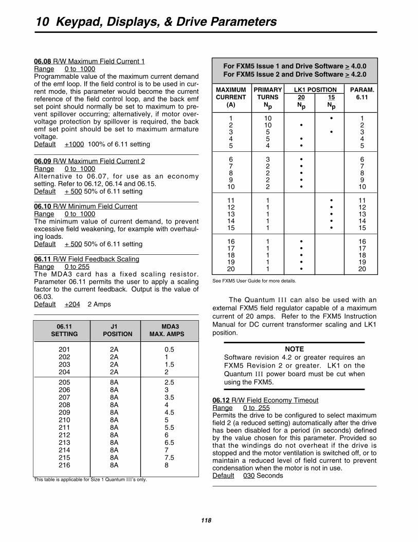
10 Keypad, Displays, & Drive Parameters
118
See FXM5 User Guide for more details.
The Quantum III can also be used with anexternal FXM5 field regulator capable of a maximumcurrent of 20 amps. Refer to the FXM5 InstructionManual for DC current transformer scaling and LK1position.
NOTESoftware revision 4.2 or greater requires anFXM5 Revision 2 or greater. LK1 on theQuantum III power board must be cut whenusing the FXM5.
06.12 R/W Field Economy TimeoutRange 0 to 255Permits the drive to be configured to select maximumfield 2 (a reduced setting) automatically after the drivehas been disabled for a period (in seconds) definedby the value chosen for this parameter. Provided sothat the windings do not overheat if the drive isstopped and the motor ventilation is switched off, or tomaintain a reduced level of field current to preventcondensation when the motor is not in use.Default 030 Seconds
06.08 R/W Maximum Field Current 1Range 0 to 1000Programmable value of the maximum current demandof the emf loop. If the field control is to be used in cur-rent mode, this parameter would become the currentreference of the field control loop, and the back emfset point should normally be set to maximum to pre-vent spillover occurring; alternatively, if motor over-voltage protection by spillover is required, the backemf set point should be set to maximum armaturevoltage.Default +1000 100% of 6.11 setting
06.09 R/W Maximum Field Current 2Range 0 to 1000Alternative to 06.07, for use as an economysetting. Refer to 06.12, 06.14 and 06.15.Default + 500 50% of 6.11 setting
06.10 R/W Minimum Field CurrentRange 0 to 1000The minimum value of current demand, to preventexcessive field weakening, for example with overhaul-ing loads.Default + 500 50% of 6.11 setting
06.11 R/W Field Feedback ScalingRange 0 to 255The MDA3 card has a f ixed scaling resistor.Parameter 06.11 permits the user to apply a scalingfactor to the current feedback. Output is the value of06.03.Default +204 2 Amps
06.11 J1 MDA3SETTING POSITION MAX. AMPS
201 2A 0.5202 2A 1203 2A 1.5204 2A 2
205 8A 2.5206 8A 3207 8A 3.5208 8A 4209 8A 4.5210 8A 5211 8A 5.5212 8A 6213 8A 6.5214 8A 7215 8A 7.5216 8A 8
This table is applicable for Size 1 Quantum III’s only.
For FXM5 Issue 1 and Drive Software > 4.0.0For FXM5 Issue 2 and Drive Software > 4.2.0
MAXIMUM PRIMARY LK1 POSITION PARAM.CURRENT TURNS 20 15 6.11
(A) Np Np Np
1 10 • 12 10 • 23 5 • 34 5 • 45 4 • 5
6 3 • 67 2 • 78 2 • 89 2 • 910 2 • 10
11 1 • 1112 1 • 1213 1 • 1314 1 • 1415 1 • 15
16 1 • 1617 1 • 1718 1 • 1819 1 • 1920 1 • 20
10 Keypad, Displays, & Drive Parameters
119
06.13 R/W Enable Field ControlEnables internal software control of the field currentregulator.Default 0, disabled
06.14 R/W Maximum Field 2 SelectorSet to 1 to engage maximum field 2. Controlled auto-matically by field economy timeout function if 06.15 isset to 1. Maximum field 2 is selected after a time delay(refer to 06.12) when a drive disable signal is given.Default 0, disabled
*06.15 R/W Enable Field Economy TimeoutWhen enabled (=1), parameter 06.14 is automaticallycontrolled by the field economy timeout function whena drive enable signal is removed. When the timeout isdisabled, parameter 06.14 becomes user R/W.Default 1, enable (Quantum factory setting)
0, disabled (Drive default)
06.16 R/W Field Time-Constant Selectorset 06.16=1 for time constant > 0.3 sec.set 06.16=0 for time constant < 0.3 sec. (default)Default 1, disabled
06.17 R/W Voltage Loop Integral GainSet 06.17 = 1 to double the integral gain if less over-shoot is desired.Default 0, disabled
06.18 R/W Enable Speed Gain AdjustmentThis parameter adjusts the speed loop gains (menu03) to compensate for the weakening of the field flux infield control mode so that the torque response remainssubstantially constant throughout the whole speedrange. Defined as—
G = 06.0806.02
Where G = Speed loop gain adjustment factorDefault 0, disabled
06.19 R/W Direct Firing Angle ControlEnables 06.09 to control the firing angle directly, sub-ject only to the front endstop. Permits operation with-out the voltage or the current loop, for the purpose ofsetup and troubleshooting.
Default 0, disabled
CAUTION
In this mode, there is no protection againstexcessive field voltage and current.
06.20 R/W Alternative IR Comp. 2 SelectorDetermines the source of the IR Compensation 2.The source selection may be either the Speed ErrorIntegral (03.08) or the Hard Speed Reference, REF 4(01.20).Default 0, 03.08 1=01.20 (Ref. 4)
*06.21 R/W Firing Angle Front EndstopRange 0 to 1000Restricts the advance of the firing angle in caseswhere 180° advance would result in overvoltage beingapplied to the field windings.Default 815 (Quantum factory setting)
1000 (Drive default)
06.22 R/W Full or Half Control SelectorProvides the option of full or half control. Availableonly with the FXM5 Field Controller. Please refer tothe FXM5 Manual for complete details.Default 0, half control
Full control only for fast field weakening
06.23 RWB Reduce Gain by Factor 2When enabled, reduces field loop current gain by afactor of 2. Can be used with 6.24 to reduce gains bya factor of 8.Default 0
06.24 RWB Reduce Gain by Factor 4When enabled, reduces field loop current gain by afactor of 4. Can be used with 6.23 to reduce gains bya factor of 8.Default 0
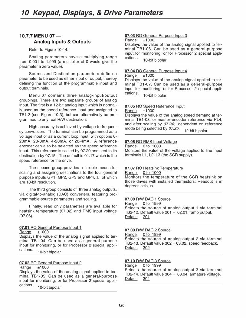
10 Keypad, Displays, & Drive Parameters
120
10.7.7 MENU 07 —Analog Inputs & Outputs
Refer to Figure 10-14.
Scaling parameters have a multiplying rangefrom 0.001 to 1.999 (a multiplier of 0 would give theparameter a zero value).
Source and Destination parameters define aparameter to be used as either input or output, therebydefining the function of the programmable input andoutput terminals.
Menu 07 contains three analog-input/outputgroupings. There are two separate groups of analoginput. The first is a 12-bit analog input which is normal-ly used as the speed reference input and assigned toTB1-3 (see Figure 10-3), but can alternatively be pro-grammed to any real R/W destination.
High accuracy is achieved by voltage-to-frequen-cy conversion. The terminal can be programmed as avoltage input or as a current loop input, with options 0-20mA, 20-0mA, 4-20mA, or 20-4mA. A referenceencoder can also be selected as the speed referenceinput. This reference is scaled by 07.20 and sent to itsdestination by 07.15. The default is 01.17 which is thespeed reference for the drive.
The second group provides a flexible means forscaling and assigning destinations to the four generalpurpose inputs GP1, GP2, GP3 and GP4, all of whichare 10-bit resolution.
The third group consists of three analog outputs,via digital-to-analog (DAC) converters, featuring pro-grammable-source parameters and scaling.
Finally, read only parameters are available forheatsink temperature (07.02) and RMS input voltage(07.06).
07.01 RO General Purpose Input 1Range ±1000Displays the value of the analog signal applied to ter-minal TB1-04. Can be used as a general-purposeinput for monitoring, or for Processor 2 special appli-cations.
10-bit bipolar
07.02 RO General Purpose Input 2Range ±1000Displays the value of the analog signal applied to ter-minal TB1-05. Can be used as a general-purposeinput for monitoring, or for Processor 2 special appli-cations.
10-bit bipolar
07.03 RO General Purpose Input 3Range ±1000Displays the value of the analog signal applied to ter-minal TB1-06. Can be used as a general-purposeinput for monitoring, or for Processor 2 special appli-cations.
10-bit bipolar
07.04 RO General Purpose Input 4Range ±1000Displays the value of the analog signal applied to ter-minal TB1-07. Can be used as a general-purposeinput for monitoring, or for Processor 2 special appli-cations.
10-bit bipolar
07.05 RO Speed Reference InputRange ±1000Displays the value of the analog speed demand at ter-minal TB1-03, or master encoder reference via PL4,and after scaling by 07.24; dependent on referencemode being selected by 07.25.
12-bit bipolar
07.06 RO RMS Input VoltageRange 0 to 1000Monitors the value of the voltage applied to line inputterminals L1, L2, L3 (the SCR supply).
07.07 RO Heatsink TemperatureRange 0 to 1000Monitors the temperature of the SCR heatsink onthose drives with installed thermistors. Readout is indegrees celsius.
07.08 R/W DAC 1 SourceRange 0 to 1999Selects the source of analog output 1 via terminalTB2-12. Default value 201 = 02.01, ramp output.Default 201
07.09 R/W DAC 2 SourceRange 0 to 1999Selects the source of analog output 2 via terminalTB2-13. Default value 302 = 03.02, speed feedback.Default 302
07.10 R/W DAC 3 SourceRange 0 to 1999Selects the source of analog output 3 via terminalTB2-14. Default value 304 = 03.04, armature voltage.Default 304

10 Keypad, Displays, & Drive Parameters
121
NOTEConcerning the following “invisible” parame-ters, scaling parameters have a multiplyingrange from 0.000 to 1.999. Source andDestination parameters define a parameterto be used as either input or output, therebydefining the function of the programmableinput and output terminals.
07.11 R/W GP 1 DestinationRange 0 to 1999 (see appendix D)Selects the destination of analog input 1 via terminalTB1-04. Default value 318=03.18, hard speed refer-ence. A changed value becomes effective only when theRESET pushbutton is pressed.Default 318
*07.12 R/W GP 2 DestinationRange 0 to 1999 (see appendix D)Selects the destination of analog input 2 via terminalTB1-05. Default value 408=4.08, speed reference 3. A changed value becomes effective only when theRESET pushbutton is pressed.Default 119 (factory default)
*07.13 R/W GP 3 DestinationRange 0 to 1999 (see appendix D)Selects the destination of analog input 3 via terminalTB1-06. Default value 119=01.19, speed reference4. A changed value becomes effective only when theRESET pushbutton is pressed.Default 120 (factory default)
07.14 R/W GP 4 DestinationRange 0 to 1999 (see appendix D)Selects the destination of analog input 4 via terminalTB1-07. Default value 120=1.20, torque reference.
A changed value becomes effective only when theRESET pushbutton is pressed.Default 408
07.15 R/W Speed Reference DestinationRange 0 to 1999Selects the destination of speed reference 07.05.Default value 117=01.17, speed reference 1.
A changed value becomes effective only when theRESET pushbutton is pressed.Default 117
07.16 R/W GP 1 ScalingRange 0 to 1999Sets the scaling for the signal from source GP1 viaterminal TB1-04.
Scaling factor = 07.161000
Default +1000 x 1.000
07.17 R/W GP 2 ScalingRange 0 to 1999Sets the scaling for the signal from source GP2 viaterminal TB1-05.
Scaling factor = 07.171000
Default +1000 x 1.000
07.18 R/W GP 3 ScalingRange 0 to 1999Sets the scaling for the signal from source GP3 viaterminal TB1-06.
Scaling factor = 07.181000
Default +1000 x 1.000
07.19 R/W GP 4 ScalingRange 0 to 1999Sets the scaling for the signal from source GP4 viaterminal TB1-07.
Scaling factor = 07.191000
Default +1000 x 1.000
07.20 R/W Speed Reference ScalingRange 0 to 1999The factor by which 07.05 is multiplied to produce thespeed reference. Used to set maximum speed underdefaults after feedback has been scaled.
Scaling factor = 07.201000
Default +1000 x 1.000
*Refer to paragraph 10.4.2.
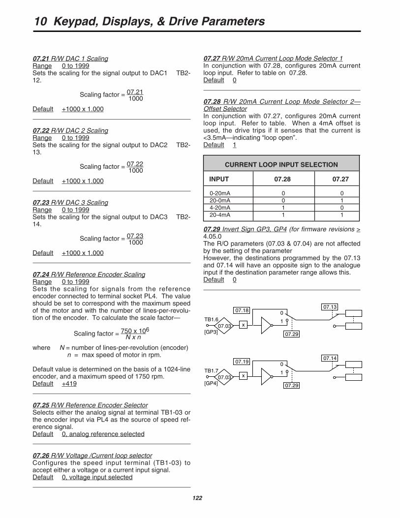
10 Keypad, Displays, & Drive Parameters
122
CURRENT LOOP INPUT SELECTION
INPUT 07.28 07.27
0-20mA 0 020-0mA 0 14-20mA 1 020-4mA 1 1
07.21 R/W DAC 1 ScalingRange 0 to 1999Sets the scaling for the signal output to DAC1 TB2-12.
Scaling factor = 07.211000
Default +1000 x 1.000
07.22 R/W DAC 2 ScalingRange 0 to 1999Sets the scaling for the signal output to DAC2 TB2-13.
Scaling factor = 07.221000
Default +1000 x 1.000
07.23 R/W DAC 3 ScalingRange 0 to 1999Sets the scaling for the signal output to DAC3 TB2-14.
Scaling factor = 07.231000
Default +1000 x 1.000
07.24 R/W Reference Encoder ScalingRange 0 to 1999Sets the scaling for signals from the referenceencoder connected to terminal socket PL4. The valueshould be set to correspond with the maximum speedof the motor and with the number of lines-per-revolu-tion of the encoder. To calculate the scale factor—
Scaling factor = 750 x 106N x n
where N = number of lines-per-revolution (encoder)n = max speed of motor in rpm.
Default value is determined on the basis of a 1024-lineencoder, and a maximum speed of 1750 rpm.Default +419
07.25 R/W Reference Encoder SelectorSelects either the analog signal at terminal TB1-03 orthe encoder input via PL4 as the source of speed ref-erence signal.Default 0, analog reference selected
07.26 R/W Voltage /Current loop selectorConfigures the speed input terminal (TB1-03) toaccept either a voltage or a current input signal.Default 0, voltage input selected
07.27 R/W 20mA Current Loop Mode Selector 1In conjunction with 07.28, configures 20mA currentloop input. Refer to table on 07.28.Default 0
07.28 R/W 20mA Current Loop Mode Selector 2—Offset SelectorIn conjunction with 07.27, configures 20mA currentloop input. Refer to table. When a 4mA offset isused, the drive trips if it senses that the current is<3.5mA—indicating “loop open”.Default 1
07.29 Invert Sign GP3, GP4 (for firmware revisions >4.05.0The R/O parameters (07.03 & 07.04) are not affectedby the setting of the parameterHowever, the destinations programmed by the 07.13and 07.14 will have an opposite sign to the analogueinput if the destination parameter range allows this.Default 0
07.18
TB1.6
[GP3] 07.29
0
1
07.13
07.03
07.19
TB1.7
[GP4] 07.29
0
1
07.14
07.03
x
x
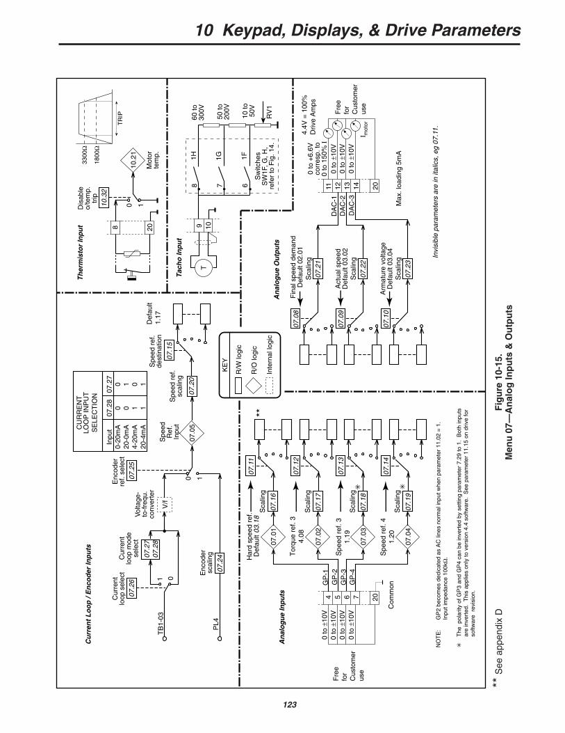
10 Keypad, Displays, & Drive Parameters
123
Fig
ure
10-
15.
Men
u 0
7—A
nal
og
Inp
uts
& O
utp
uts
01
07.2
6
Cur
rent
loop
sel
ect
07.2
707
.28
V/f
Volta
ge-
to-f
requ
.co
nver
ter
0 107.2
5
Enc
oder
re
f. se
lect
07.2
4
Enc
oder
sc
alin
gP
L4
07.0
507
.20
Spe
ed r
ef.
scal
ing
Spe
ed r
ef.
dest
inat
ion
TB
1-03
07.1
907
.04
07.1
4
Cur
rent
loop
mod
ese
lect
07.2
80 0 1 1
07.2
70 1 0 1
Inpu
t0-
20m
A20
-0m
A4-
20m
A20
-4m
ACU
RR
EN
TLO
OP
INP
UT
SE
LEC
TIO
N
R/W
logi
c
R/O
logi
c
Inte
rnal
logi
c
KE
Y
Invi
sibl
e pa
ram
eter
s ar
e in
ital
ics,
eg
07.1
1.
Spe
edR
ef.
Inpu
t
Sca
ling
204 5 6 707
.18
07.0
3
07.1
3
Sca
ling
07.1
707
.02
07.1
2
Sca
ling
Tor
que
ref.
34.
08
07.1
607
.01
07.1
1
Sca
ling
Har
d sp
eed
ref.
Def
ault
03.1
8
0 to
±10
V0
to ±
10V
0 to
±10
V
0 to
±10
V
An
alo
gu
e In
pu
ts
07.2
3
07.1
0
Sca
ling
Arm
atur
e vo
ltage
Def
ault
03.0
4M
ax. l
oadi
ng 5
mA
2011 12 13 1407
.22
07.0
9
Sca
ling
Act
ual s
peed
Def
ault
03.0
2
07.2
1
07.0
8
Sca
ling
Fin
al s
peed
dem
and
Def
ault
02.0
1
0 to
±10
V0
to ±
10V
0 to
±10
V
0 to
+6.
6Vco
rres
p. to
0 to
150
% I
An
alo
gu
e O
utp
uts
DA
C-1
DA
C-2
DA
C-3
I mot
or
GP
-1G
P-2
GP
-3
NO
TE
:G
P2
beco
mes
ded
icat
ed a
s A
C li
nes
norm
al in
put w
hen
para
met
er 1
1.02
= 1
.In
put i
mpe
danc
e 10
0kΩ
.
T
he p
olar
ity o
f GP
3 an
d G
P4
can
be in
vert
ed b
y se
tting
par
amet
er 7
.29
to 1
. B
oth
inpu
ts
are
inve
rted
. T
his
appl
ies
only
to v
ersi
on 4
.4 s
oftw
are.
See
par
amet
er 1
1.15
on
driv
e fo
r so
ftwar
e r
evis
ion.
GP
-4
8
07.1
5
Cu
rren
t L
oo
p /
En
cod
er In
pu
tsT
her
mis
tor
Inp
ut 20
0 110.3
2
Dis
able
o/
tem
p.
trip
10.2
1
Mot
orte
mp.
TR
IP
3300
Ω
1800
Ω
9 10T
Tach
o In
pu
t
1H 1G 1F678
60 to
30
0V
50 to
20
0V
10 to
50
V
RV
1
Sw
itche
sS
W1F
, G, H
,re
fer
to F
ig. 1
4.**
Fre
e fo
rC
usto
mer
use
Fre
e fo
rC
usto
mer
use
4.4V
= 1
00%
Driv
e A
mps
Def
ault
1.17
Spe
ed r
ef. 3
1.19
Spe
ed r
ef. 4
1.20
Com
mon
**S
ee a
ppen
dix
D
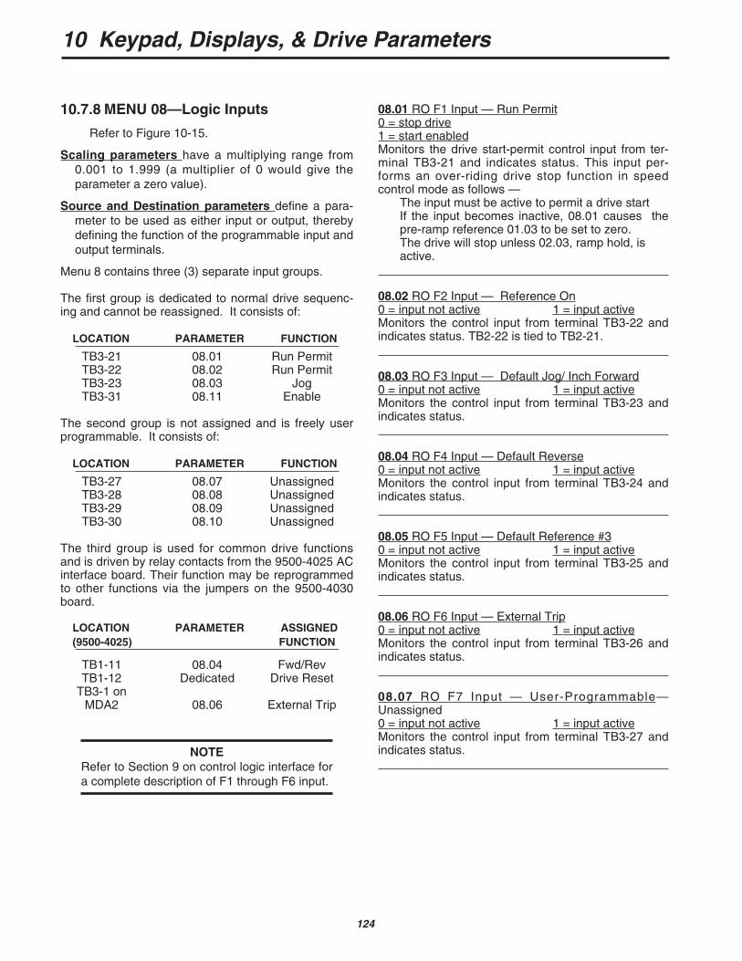
10 Keypad, Displays, & Drive Parameters
124
08.01 RO F1 Input — Run Permit0 = stop drive1 = start enabledMonitors the drive start-permit control input from ter-minal TB3-21 and indicates status. This input per-forms an over-riding drive stop function in speedcontrol mode as follows —
The input must be active to permit a drive startIf the input becomes inactive, 08.01 causes thepre-ramp reference 01.03 to be set to zero.The drive will stop unless 02.03, ramp hold, is active.
08.02 RO F2 Input — Reference On0 = input not active 1 = input activeMonitors the control input from terminal TB3-22 andindicates status. TB2-22 is tied to TB2-21.
08.03 RO F3 Input — Default Jog/ Inch Forward0 = input not active 1 = input activeMonitors the control input from terminal TB3-23 andindicates status.
08.04 RO F4 Input — Default Reverse0 = input not active 1 = input activeMonitors the control input from terminal TB3-24 andindicates status.
08.05 RO F5 Input — Default Reference #30 = input not active 1 = input activeMonitors the control input from terminal TB3-25 andindicates status.
08.06 RO F6 Input — External Trip0 = input not active 1 = input activeMonitors the control input from terminal TB3-26 andindicates status.
08.07 RO F7 Input — User-Programmable—Unassigned0 = input not active 1 = input activeMonitors the control input from terminal TB3-27 andindicates status.
10.7.8 MENU 08—Logic Inputs
Refer to Figure 10-15.
Scaling parameters have a multiplying range from0.001 to 1.999 (a multiplier of 0 would give theparameter a zero value).
Source and Destination parameters define a para-meter to be used as either input or output, therebydefining the function of the programmable input andoutput terminals.
Menu 8 contains three (3) separate input groups.
The first group is dedicated to normal drive sequenc-ing and cannot be reassigned. It consists of:
LOCATION PARAMETER FUNCTION
TB3-21 08.01 Run PermitTB3-22 08.02 Run PermitTB3-23 08.03 JogTB3-31 08.11 Enable
The second group is not assigned and is freely userprogrammable. It consists of:
LOCATION PARAMETER FUNCTION
TB3-27 08.07 UnassignedTB3-28 08.08 UnassignedTB3-29 08.09 UnassignedTB3-30 08.10 Unassigned
The third group is used for common drive functionsand is driven by relay contacts from the 9500-4025 ACinterface board. Their function may be reprogrammedto other functions via the jumpers on the 9500-4030board.
LOCATION PARAMETER ASSIGNED(9500-4025) FUNCTION
TB1-11 08.04 Fwd/RevTB1-12 Dedicated Drive Reset
TB3-1 onMDA2 08.06 External Trip
NOTERefer to Section 9 on control logic interface fora complete description of F1 through F6 input.
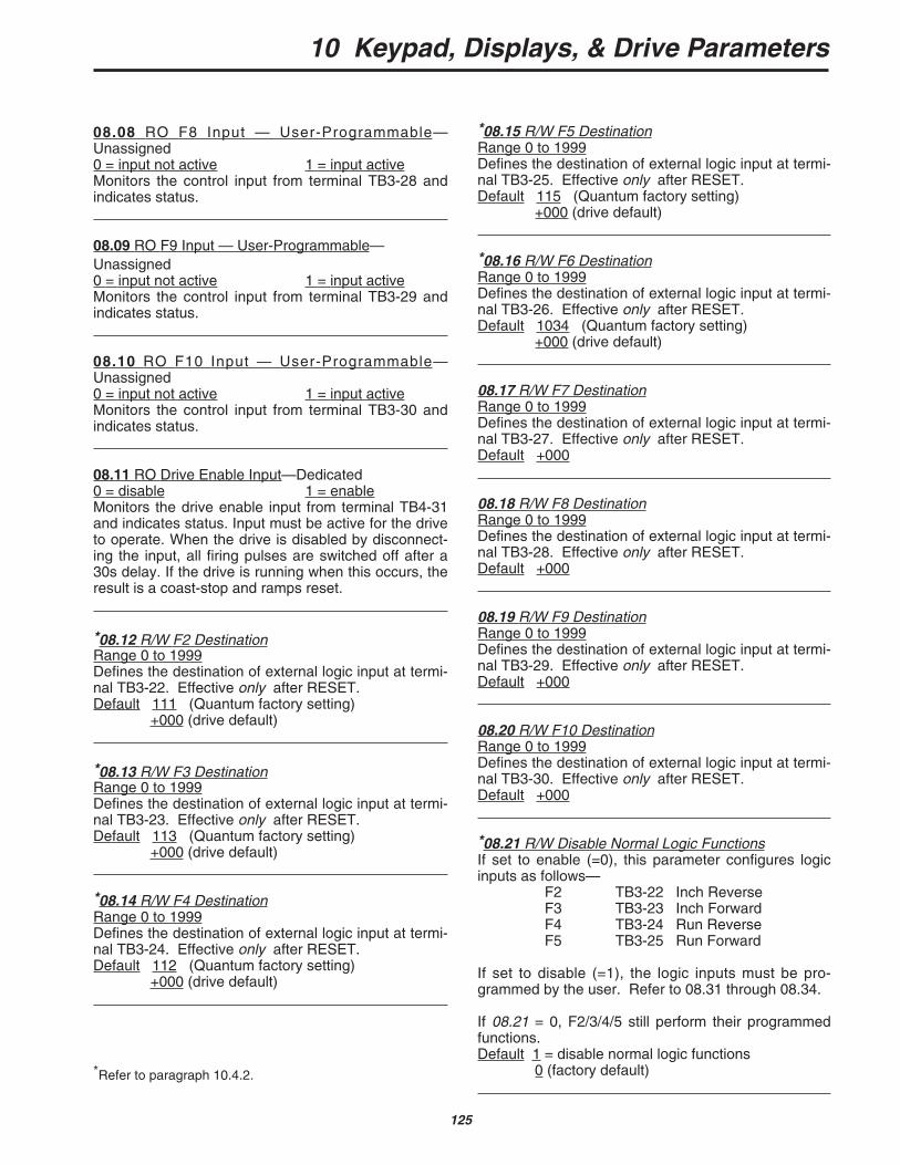
10 Keypad, Displays, & Drive Parameters
125
*08.15 R/W F5 DestinationRange 0 to 1999Defines the destination of external logic input at termi-nal TB3-25. Effective only after RESET.Default 115 (Quantum factory setting)
+000 (drive default)
*08.16 R/W F6 DestinationRange 0 to 1999Defines the destination of external logic input at termi-nal TB3-26. Effective only after RESET.Default 1034 (Quantum factory setting)
+000 (drive default)
08.17 R/W F7 DestinationRange 0 to 1999Defines the destination of external logic input at termi-nal TB3-27. Effective only after RESET.Default +000
08.18 R/W F8 DestinationRange 0 to 1999Defines the destination of external logic input at termi-nal TB3-28. Effective only after RESET.Default +000
08.19 R/W F9 DestinationRange 0 to 1999Defines the destination of external logic input at termi-nal TB3-29. Effective only after RESET.Default +000
08.20 R/W F10 DestinationRange 0 to 1999Defines the destination of external logic input at termi-nal TB3-30. Effective only after RESET.Default +000
*08.21 R/W Disable Normal Logic FunctionsIf set to enable (=0), this parameter configures logicinputs as follows—
F2 TB3-22 Inch ReverseF3 TB3-23 Inch ForwardF4 TB3-24 Run ReverseF5 TB3-25 Run Forward
If set to disable (=1), the logic inputs must be pro-grammed by the user. Refer to 08.31 through 08.34.
If 08.21 = 0, F2/3/4/5 still perform their programmedfunctions.Default 1 = disable normal logic functions
0 (factory default)
08.08 RO F8 Input — User-Programmable—Unassigned0 = input not active 1 = input activeMonitors the control input from terminal TB3-28 andindicates status.
08.09 RO F9 Input — User-Programmable—Unassigned0 = input not active 1 = input activeMonitors the control input from terminal TB3-29 andindicates status.
08.10 RO F10 Input — User-Programmable—Unassigned0 = input not active 1 = input activeMonitors the control input from terminal TB3-30 andindicates status.
08.11 RO Drive Enable Input—Dedicated0 = disable 1 = enableMonitors the drive enable input from terminal TB4-31and indicates status. Input must be active for the driveto operate. When the drive is disabled by disconnect-ing the input, all firing pulses are switched off after a30s delay. If the drive is running when this occurs, theresult is a coast-stop and ramps reset.
*08.12 R/W F2 DestinationRange 0 to 1999Defines the destination of external logic input at termi-nal TB3-22. Effective only after RESET.Default 111 (Quantum factory setting)
+000 (drive default)
*08.13 R/W F3 DestinationRange 0 to 1999Defines the destination of external logic input at termi-nal TB3-23. Effective only after RESET.Default 113 (Quantum factory setting)
+000 (drive default)
*08.14 R/W F4 DestinationRange 0 to 1999Defines the destination of external logic input at termi-nal TB3-24. Effective only after RESET.Default 112 (Quantum factory setting)
+000 (drive default)
*Refer to paragraph 10.4.2.
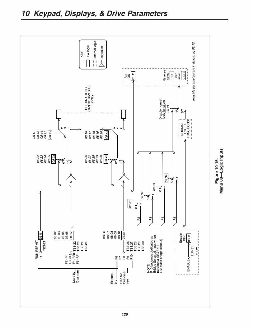
10 Keypad, Displays, & Drive Parameters
126
0 1
08.0
1
08.0
x
08.2
x08
.02
08.0
308
.04
08.0
5
08.2
208
.23
08.2
408
.25
RU
N P
ER
MIT 08
.11
0 108
.xx
08.x
x08
.06
08.0
708
.08
08.0
908
.10
08.2
608
.27
08.2
808
.29
08.3
0
NO
RM
AL
LOG
ICF
UN
CT
ION
S
0108.2
1
Dis
able
nor
mal
logi
c fu
nctio
ns
01.1
1
01.1
2
01.1
3
Ref
ON
Rev
erse
sele
ct
Inch
sele
ct
EN
AB
LET
B4-
31
Ena
ble
inpu
t
TB
3-22
TB
3.23
TB
3.24
TB
3.25
F2
(IR
)F
3 (
IF)
F4
(RR
)F
5 (R
F)
F1
TB
3-21
F6
F7
F8
F9
F10
TB
3-26
TB
3.27
TB
3.28
TB
3.29
TB
3-30
08.2
x
08.1
208
.13
08.1
408
.15
08.x
x
08.1
608
.17
08.1
808
.19
08.2
0
R/W
logi
c
Inte
rnal
logi
c
Inve
rsio
n
KE
YD
ES
TIN
AT
ION
SC
AN
BE
R/W
BIT
SO
NLY
Invi
sibl
e pa
ram
eter
s ar
e in
ital
ics,
eg
08.1
2.
0
1
08.3
1
0
1
08.3
2
0
1
08.3
3
0
1
08.3
4
F2
F3
F4
F5
NO
TE
F10
bec
omes
ded
icat
ed a
s B
ridge
Sel
ecte
d in
put w
hen
para
met
er 0
5.21
= 1
(1
2-pu
lse
brid
ge lo
ckou
t)
Use
d by
Qua
ntum
Ext
erna
ltr
ip
Fre
e fo
rC
usto
mer
use
In u
se
Fig
ure
10-
16.
Men
u 0
8—L
og
ic In
pu
ts
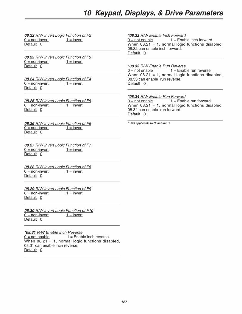
10 Keypad, Displays, & Drive Parameters
127
08.22 R/W Invert Logic Function of F20 = non-invert 1 = invertDefault 0
08.23 R/W Invert Logic Function of F30 = non-invert 1 = invertDefault 0
08.24 R/W Invert Logic Function of F40 = non-invert 1 = invertDefault 0
08.25 R/W Invert Logic Function of F50 = non-invert 1 = invertDefault 0
08.26 R/W Invert Logic Function of F60 = non-invert 1 = invertDefault 0
08.27 R/W Invert Logic Function of F70 = non-invert 1 = invertDefault 0
08.28 R/W Invert Logic Function of F80 = non-invert 1 = invertDefault 0
08.29 R/W Invert Logic Function of F90 = non-invert 1 = invertDefault 0
08.30 R/W Invert Logic Function of F100 = non-invert 1 = invertDefault 0
*08.31 R/W Enable Inch Reverse0 = not enable 1 = Enable inch reverse When 08.21 = 1, normal logic functions disabled,08.31 can enable inch reverse.Default 0
*08.32 R/W Enable Inch Forward0 = not enable 1 = Enable inch forward When 08.21 = 1, normal logic functions disabled,08.32 can enable inch forward.Default 0
*08.33 R/W Enable Run Reverse0 = not enable 1 = Enable run reverse When 08.21 = 1, normal logic functions disabled,08.33 can enable run reverse.Default 0
*08.34 R/W Enable Run Forward0 = not enable 1 = Enable run forward When 08.21 = 1, normal logic functions disabled,08.34 can enable run forward.Default 0
* Not applicable to Quantum III
10 Keypad, Displays, & Drive Parameters
128
10.7.9 MENU 09—Status Outputs
Refer to Figure 10-16.
Status outputs will switch five open collectortransistors, each user programmable, and two relays.The drive ready is dedicated and cannot be changed.The other relay is defaulted to zero speed, but is userprogrammable to any other parameter.
Menu 9 contains three status source groups andeach is invertible.
The first group allows the status 1 inputs fromsource 1 and source 2 to be combined into logic gates(OR, NOR, AND, NAND) to form PC logic. The resultcan be subjected to a time delay that is, in effect, in 0-1 transactions but immediate without delay in 1-0transactions. An output is available at TB2-15. Theprocess is duplicated with status 2 inputs and the out-put is at TB2-16. See Appendix C Logic Gates.
The second group selects parameters fromsources ST2, ST3, and ST4 for output at terminalsTB2-17, -18, and -19.
The third group selects parameters from sourcesST6 and drives the form C relay at terminals TB3-35,36, and 37.
09.01 RO Status 1 OutputRange 0 to 1Status 1 output ST1 to TB2-15.
09.02 RO Status 2 OutputRange 0 to 1Status 2 output ST2 to TB2-16
09.03 RO Status 3 OutputRange 0 to 1Status 3 output ST3 to TB2-17.
09.04 RO Status 4 OutputRange 0 to 1Status 4 output ST4 to TB2-18.
09.05 RO Status 5 OutputRange 0 to 1Status 5 output ST5 to TB2-19.
09.06 RO Status 6 Relay OutputRange 0 to 1Output to form C relay at terminals TB4-34,35,36
1 = Relay on
09.07 R/W Status 1 Source 1Range 0 to 1999Selects the status source to be combined with 9.09and displayed on TB2-15.Default +111
09.08 R/W Invert Status 1 Source 1Range 0 to 1Selects inversion of input on 9.07.Default 0 (non-invert)
09.09 R/W Status 1 Source 2Range 0 to 1999Selects the status source to be combined with 9.07and displayed on TB2-15.Default 000
09.10 R/W Invert Status 1 Source 2Range 0 to 1Selects inversion of input on 9.09.Default 0 (non-invert)
09.11 R/W Invert Status 1 OutputRange 0 to 1Selects inversion of combination of 9.07 and 9.09.Default 0 (non-invert)
09.12 R/W Status 1 DelayRange 0 to 255 (sec.)Sets delay time for status 1 output.Default 0
09.13 R/W Status 2 Source 1Range 0 to 1999Selects the status source to be combined with 9.15and displayed on TB2-16.Default 1007
09.14 R/W Invert Status 2 Source 2Range 0 to 1Selects inversion of input on 9.13.Default 0 (non-invert)
09.15 R/W Status 2 Source 2Range 0 to 1999Selects the status source to be combined with 9.13and displayed on TB2-16.Default 000
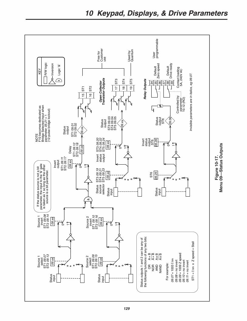
10 Keypad, Displays, & Drive Parameters
129
0 1
&
0 1
0 1
ST
109
.11
ST
209
.17
Sou
rce
1se
lect
ST
109
.07
ST
209
.13
Sou
rce
1in
vert
ST
109
.08
ST
209
.14
Sou
rce
2se
lect
ST
109
.09
ST
209
.15
ST
109
.01
ST
209
.02
09.x
x
09.x
x
09.x
x
09.x
x
09.x
x
Sou
rce
2in
vert
ST
109
.10
ST
209
.16
09.x
x
09.x
x
If th
e st
atus
sou
rce
is n
ot a
bit
para
met
er, t
he in
put t
o th
e ‘&
’ gat
e is
take
n as
1 s
o lo
ng a
s th
e ot
her
sour
ce is
a b
it pa
ram
eter
.
Sta
tus
outp
uts
1 an
d 2
can
be a
ny o
f th
e fo
llow
ing
func
tions
of a
ny tw
o bi
ts:
A +
BA
+ B
A x
BA
x B
OR
NO
RA
ND
NA
ND
For
exa
mpl
e:
09.0
7 =
100
3 I
lim
09.0
8 =
no
inve
rt09
.09
= 1
009
Z s
peed
09.1
0 =
no
inve
rt09
.11
= n
o in
vert
ST
1 =
I li
m x
Z s
peed
= S
tall
09.x
x09
.xx
0 1
Inve
rt
stat
us
outp
ut
Sta
tus
inpu
t
Sta
tus
outp
ut
Sta
tus
sour
cese
lect
orS
tatu
sin
put
Sta
tus
inpu
t
ST
309
.19
ST
409
.21
ST
509
.23
ST
309
.20
ST
409
.22
ST
509
.24
ST
309
.03
ST
409
.04
ST
509
.05
ST
1
ST
2
R/W
logi
c
Inve
rsio
n
Logi
c ‘&
’
KE
Y
&
Sta
tus
outp
utD
elay
09.x
x
ST
109
.12
ST
209
.18
Invi
sibl
e pa
ram
eter
s ar
e in
ital
ics,
eg
09.0
7.
Inve
rtou
tput
15 16
NO
TE
F10
bec
omes
ded
icat
ed a
s B
ridge
Sel
ecte
d in
put w
hen
para
met
er 0
5.21
= 1
(1
2-pu
lse
brid
ge lo
ckou
t)
09.0
6
09.2
509
.26
0 1Inve
rt
stat
us
outp
ut
ST
6S
tatu
sin
put
Sta
tus
outp
utS
T6
ST
6
Rel
ay O
utp
uts
34 35 36 37 38 39
Con
trol
led
by
para
met
er
10.1
2 (R
O)
Con
tact
load
ing
5A, 2
40V
AC
Def
ault
Zer
o sp
eed
Def
ault
Driv
e re
ady
Op
en C
olle
cto
r T
ran
sist
or
Ou
tpu
ts
ST
3
ST
4
ST
5
17 18 19U
sed
byQ
uant
um
Use
rpr
ogra
mm
able
Fre
e fo
rC
usto
mer
use
Fig
ure
10-
17.
Men
u 0
9—S
tatu
s O
utp
uts
10 Keypad, Displays, & Drive Parameters
130
09.16 R/W Invert Status 2 Source 2Range 0 to 1Selects inversion of input on 9.15.Default 0 (non-invert)
09.17 R/W Invert Status 2 OutputRange 0 to 1Selects inversion of combination of 9.13 and 9.15.Default 0 (non-invert)
09.18 R/W Status 2 DelayRange 0 to 255 (sec.)Sets delay time for status 2 output.Default 0
09.19 R/W Status 3 SourceRange 0 to 1999Selects the status source to be displayed on TB2-17.Default 1013 Overload alarm
User programmable
09.20 R/W Invert Status 3 OutputRange 0 to 1Default 0 (non-invert)
09.21 R/W Status 4 SourceRange 0 to 1999Selects the status source to be displayed on TB3-18.Default 1003 In current limit
User programmable
09.22 R/W Invert Status 4 OutputRange 0 to 1Default 0 (non-invert)
09.23 R/W Status 5 SourceRange 0 to 1999Selects the status source to be displayed on TB3-19.Default 1006 Phase back
In use by Quantum
*09.24 R/W Invert Status 5 OutputRange 0 to 1Default 1 (invert)
0 (factory default)
09.25 R/W Status 6 Source—Relay OutputRange 0 to 1999Selects the status to activate relay to TB4-34,35,36Default 1009 (Zero Speed)
User programmable
09.26 R/W Invert Status 6 OutputRange 0 to 1Default 0 (non-invert)
10 Keypad, Displays, & Drive Parameters
131
10.04 RO Bridge 1 Enabled0 = disabled 1 = enabledIndicates that SCR bridge 1 (the forward or positivebridge) is being fired. Does not necessarily indicatethat the bridge is conducting, since conductiondepends on firing angle and operating conditions.
10.05 RO Bridge 2 Enabled0 = disabled 1 = enabledIndicates that SCR bridge 2 (the reverse or negativebridge) is being fired. Does not necessarily indicatethat the bridge is conducting, since conductiondepends on firing angle and operating conditions.
10.06 RO Electrical Phase-Back0 = firing pulses not phased back1 = firing pulses phased back (at standstill)Indicates that the firing pulses are being phased backby the action of the standstill function. Refer to 05.18and 05.19.
10.07 RO At Speed0 = drive not at speed 1 = drive at speedIndicates that the drive has attained set speed, post-ramp reference 02.01 = pre-ramp reference 01.03,and that comparison of final speed demand 03.01with speed feedback 03.02 results in a speed error of<1.5% of maximum speed. External signal also pro-vided through open collector output ST2 to terminalTB2-16 if source parameter 09.13 is at default setting.
10.08 RO Overspeed0 = motor not overspeeding1 = motor over speedIndicates that the speed feedback 03.02 > ±1000, thatis, the speed is out of range, suggesting that themotor is being mechanically driven faster than themaximum speed of the drive. This function is a moni-tor only, and does not initiate a trip signal.
10.09 RO Zero Speed0 = speed not zero 1 = zero speedSet if speed feedback 03.02 < zero speed threshold03.23. Refer to 10.01 and 10.02.
10.10 RO Armature Voltage Clamp Active0 = clamp not active 1 = clamp activeSet when the armature voltage clamp isactivated. Prevents the voltage from increasing fur-ther. Refer to 03.15.
10.7.10 MENU 10 — Status Logic & Diagnostic Information
All real (not bit) RO parameters are frozen at theinstant of tripping as an aid to diagnosis of thefault. They remain in this condition until the drive isreset. The last four faults are stored in 10.25 through10.28 to form a fault history.
10.01 RO Forward Velocity0 = drive stationary or running in reverse1 = drive running forward at >zero speed thresholdForward direction defined as —
When tach feedback selected, terminal TB1-09negative with respect to terminal TB1-10.When armature voltage feedback selected, termi-nal A1 positive with respect to terminal A2.When encoder feedback selected, A-channel leads B-channel.
10.02 RO Reverse Velocity0 = drive stationary or running forward1 = drive running in reverse at >zero speed thresholdReverse direction defined as follows —
When tach feedback selected, terminal TB1-09positive with respect to terminal TB1-10.When armature voltage feedback selected, termi-nal A1 negative with respect to terminal A2.When encoder feedback selected, A-channel lagsB-channel.
NOTEIf 10.01 = 10.02 = 0, the motor is either sta-tionary or running at <zero speed threshold. Inthis condition, 10.09 = 1 and the Zero SpeedLED lights on the keypad (and RL2 is turnedon, if programmed to show zero speed).
10.03 RO Current Limit0 = drive not in current limit1 = drive in current limitIndicates that the sum of the current demand 04.01and the offset 04.09 is being limited by the currentlimit over-ride 04.03 or by one of the bridge limits.
10 Keypad, Displays, & Drive Parameters
132
10.11 RO Phase Rotation0 = L1 L3 L2 1 = L1 L2 L3Rotation is detected from L1, L2, L3.NOTE that connection to E1 and E3 must also be cor-rect — refer to the drawings shown in Figures A-1through A-4 in Appendix A.
10.12 RO Drive Normal1 = drive is powered-up and has not tripped.
10.13 RO Alarm0 = no alarm condition present1 = alarm condition present, impending sustained-overload trip Indicates that the drive is in an overload condition andwill eventually trip on sustained overload 10.18 if theoverload condition is not removed. The time taken totrip is dependent on the settings of 05.06 and 05.07and on the magnitude of overload.Visual indication that the alarm has been actuated isgiven by the Alarm LED (flashing). External signal alsoprovided through status logic output ST3 to terminalTB2-17—provided that source parameter 09.19 is itsdefault value.
10.14 RO Field Loss0 = field normal 1 = field failedIndicates that no current is being drawn from the inter-nal field supply (or the FXM5 optional external fieldcontrol unit if installed).
10.15 RO Feedback Loss0 = speed feedback present1 = speed feedback absent or polarity reversedIndicates no feedback signal, or reversedpolarity. Applies to tachometer or encoder feedback,whichever is selected. Loss of feedback is not detect-ed until the firing angle has advanced to the pointwhere the value of 05.03 (firing angle) >767. Thiscondition can be prevented from tripping the drive bydisabling feedback loss detection 10.30.
10.16 RO Supply or Phase Loss0 = normal1 = supply/phase lossIndicates loss of one or more input phases connectedto L1, L2, L3. Can be disabled with 10.31.
10.17 RO Instantaneous Trip0 = no overcurrent peak detected1 = overcurrent peak detectedIndicates that a current peak >2 x (max. currentaccording to the burden resistor installed) hasoccurred. Firing pulses are immediately suppressed,shutting the drive down.
10.18 RO Sustained Overload0 = sustained overload not detected1 = sustained overload detectedIndicates that current feedback 05.01 has exceededthe overload threshold 05.06 for a length of timedetermined by the overload time values 05.07 and05.08 integrated with the magnitude of the overload(the conventional I x t function).
When the current exceeds the overload threshold, theexcess integrates with time causing the value of theactual overload 05.11 to increase.
Conversely, if the current falls below the thresholdduring integration, the value of 05.11 falls towardszero. The rate of integration is set by 05.07 when thecurrent is > threshold, and by 05.08 when the currentis < threshold. The rate of integration is the trip timewith full scale overload (05.01 = 1000). This functionimitates the behavior of a thermal relay and simulatesthe thermal characteristic of a motor.
10.19 RO Processor 1 Watchdog0 = normal 1 = tripIn normal operation of the drive, the watchdog timer isreset periodically by Processor 1 as a check that theprocessor and drive program are functioning normal-ly. If a reset does not occur before the timer has timedout, the conclusion is either that the processor hasfailed or that the drive program has crashed. Theresult is immediate controlled shutdown of the drive,accompanied by a watchdog fault trip signal.
10.20 RO Processor 2 Watchdog0 = normal 1 = trip
10.21 RO Motor Overtemperature0 = normal 1 = trip10.21 = 1 indicates trip detected at the motor thermis-tor input terminal.
trip level 3kΩdetector reset level 1.8kΩ
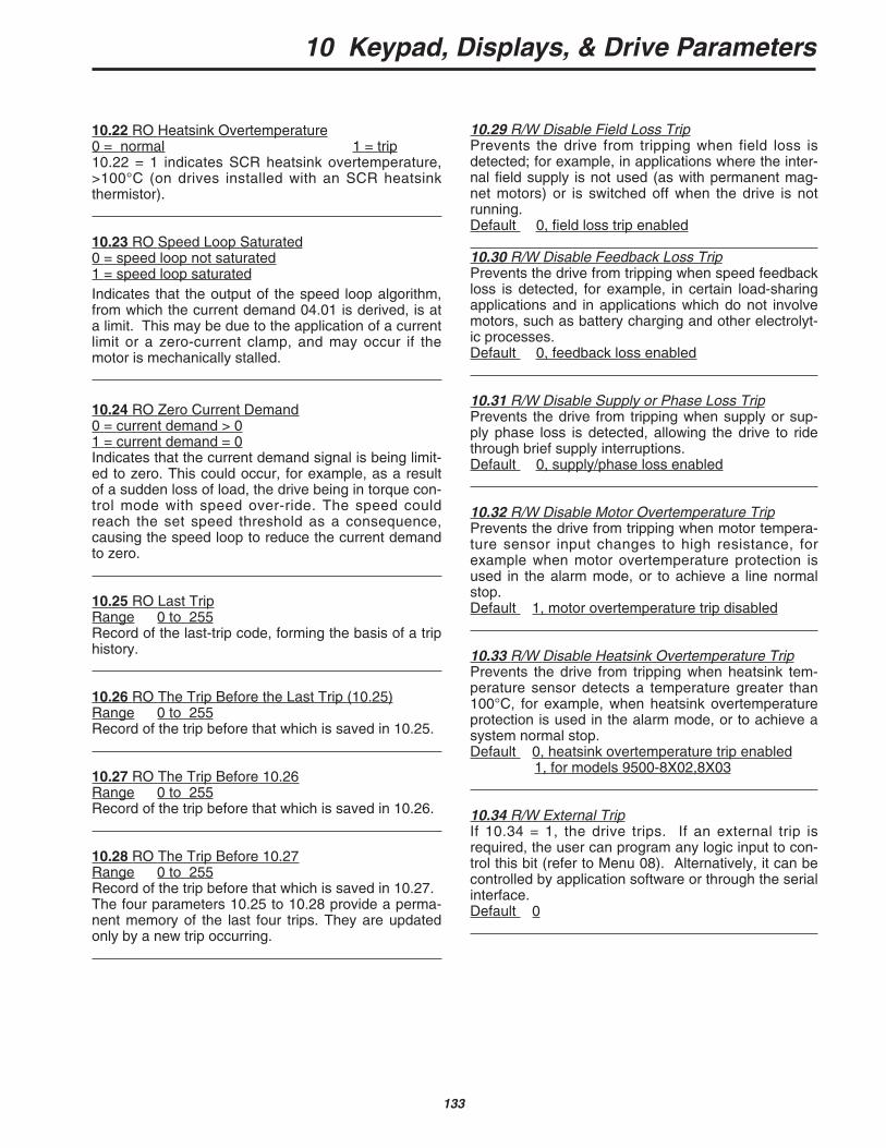
10 Keypad, Displays, & Drive Parameters
133
10.29 R/W Disable Field Loss TripPrevents the drive from tripping when field loss isdetected; for example, in applications where the inter-nal field supply is not used (as with permanent mag-net motors) or is switched off when the drive is notrunning.Default 0, field loss trip enabled
10.30 R/W Disable Feedback Loss TripPrevents the drive from tripping when speed feedbackloss is detected, for example, in certain load-sharingapplications and in applications which do not involvemotors, such as battery charging and other electrolyt-ic processes.Default 0, feedback loss enabled
10.31 R/W Disable Supply or Phase Loss TripPrevents the drive from tripping when supply or sup-ply phase loss is detected, allowing the drive to ridethrough brief supply interruptions.Default 0, supply/phase loss enabled
10.32 R/W Disable Motor Overtemperature TripPrevents the drive from tripping when motor tempera-ture sensor input changes to high resistance, forexample when motor overtemperature protection isused in the alarm mode, or to achieve a line normalstop.Default 1, motor overtemperature trip disabled
10.33 R/W Disable Heatsink Overtemperature TripPrevents the drive from tripping when heatsink tem-perature sensor detects a temperature greater than100°C, for example, when heatsink overtemperatureprotection is used in the alarm mode, or to achieve asystem normal stop.Default 0, heatsink overtemperature trip enabled
1, for models 9500-8X02,8X03
10.34 R/W External TripIf 10.34 = 1, the drive trips. If an external trip isrequired, the user can program any logic input to con-trol this bit (refer to Menu 08). Alternatively, it can becontrolled by application software or through the serialinterface.Default 0
10.22 RO Heatsink Overtemperature0 = normal 1 = trip10.22 = 1 indicates SCR heatsink overtemperature,>100°C (on drives installed with an SCR heatsinkthermistor).
10.23 RO Speed Loop Saturated0 = speed loop not saturated1 = speed loop saturatedIndicates that the output of the speed loop algorithm,from which the current demand 04.01 is derived, is ata limit. This may be due to the application of a currentlimit or a zero-current clamp, and may occur if themotor is mechanically stalled.
10.24 RO Zero Current Demand0 = current demand > 01 = current demand = 0Indicates that the current demand signal is being limit-ed to zero. This could occur, for example, as a resultof a sudden loss of load, the drive being in torque con-trol mode with speed over-ride. The speed couldreach the set speed threshold as a consequence,causing the speed loop to reduce the current demandto zero.
10.25 RO Last TripRange 0 to 255Record of the last-trip code, forming the basis of a triphistory.
10.26 RO The Trip Before the Last Trip (10.25)Range 0 to 255Record of the trip before that which is saved in 10.25.
10.27 RO The Trip Before 10.26Range 0 to 255Record of the trip before that which is saved in 10.26.
10.28 RO The Trip Before 10.27Range 0 to 255Record of the trip before that which is saved in 10.27.The four parameters 10.25 to 10.28 provide a perma-nent memory of the last four trips. They are updatedonly by a new trip occurring.
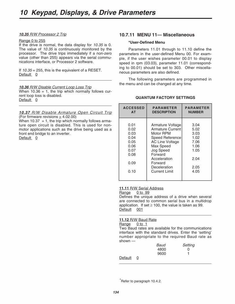
10 Keypad, Displays, & Drive Parameters
134
10.35 R/W Processor 2 Trip
Range 0 to 255If the drive is normal, the data display for 10.35 is 0.The value of 10.35 is continuously monitored by theprocessor. The drive trips immediately if a non-zerovalue (other than 255) appears via the serial commu-nications interface, or Processor 2 software.
If 10.35 = 255, this is the equivalent of a RESET. Default 0
10.36 R/W Disable Current Loop Loss TripWhen 10.36 = 1, the trip which normally follows cur-rent loop loss is disabled.Default 0
10.37 R/W Disable Armature Open Circuit Trip(For firmware revisions > 4.02.00)When 10.37 = 1, the trip which normally follows arma-ture open circuit is disabled. This is used for non-motor applications such as the drive being used as afront end bridge to an inverter.Default 0
10.7.11 MENU 11— Miscellaneous
*User-Defined Menu
Parameters 11.01 through to 11.10 define theparameters in the user-defined Menu 00. For exam-ple, if the user wishes parameter 00.01 to displayspeed in rpm (03.03), parameter 11.01 (correspond-ing to 00.01) should be set to 303. Other miscella-neous parameters are also defined.
The following parameters are programmed inthe menu and can be changed at any time.
QUANTUM FACTORY SETTINGS
ACCESSED PARAMETER PARAMETERAT DESCRIPTION NUMBER
0.01 Armature Voltage 3.040.02 Armature Current 5.020.03 Motor RPM 3.030.04 Speed Reference 1.020.05 AC Line Voltage 7.060.06 Max Speed 1.060.07 Jog Speed 1.050.08 Forward
Acceleration 2.040.09 Forward
Deceleration 2.050.10 Current Limit 4.05
11.11 R/W Serial AddressRange 0 to 99Defines the unique address of a drive when severalare connected to common serial bus in a multidropapplication. If set ≥ 100, the value is taken as 99.Default 001
11.12 R/W Baud RateRange 0 to 1Two Baud rates are available for the communicationsinterface with the standard drives. Enter the ‘setting’number appropriate to the required Baud rate asshown —
Baud Setting4800 09600 1
Default 0
*Refer to paragraph 10.4.2.
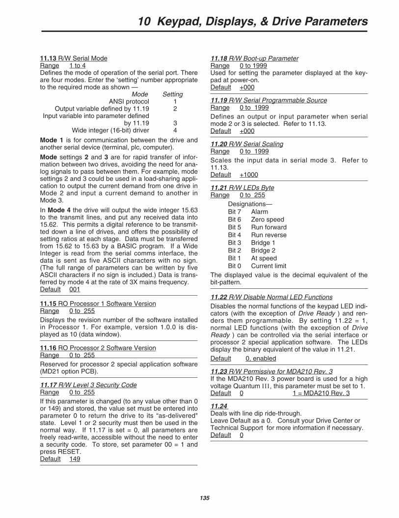
10 Keypad, Displays, & Drive Parameters
135
11.18 R/W Boot-up ParameterRange 0 to 1999Used for setting the parameter displayed at the key-pad at power-on.Default +000
11.19 R/W Serial Programmable SourceRange 0 to 1999Defines an output or input parameter when serialmode 2 or 3 is selected. Refer to 11.13.Default +000
11.20 R/W Serial ScalingRange 0 to 1999Scales the input data in serial mode 3. Refer to11.13.Default +1000
11.21 R/W LEDs ByteRange 0 to 255
Designations— Bit 7 AlarmBit 6 Zero speedBit 5 Run forwardBit 4 Run reverseBit 3 Bridge 1Bit 2 Bridge 2Bit 1 At speedBit 0 Current limit
The displayed value is the decimal equivalent of thebit-pattern.
11.22 R/W Disable Normal LED FunctionsDisables the normal functions of the keypad LED indi-cators (with the exception of Drive Ready ) and ren-ders them programmable. By setting 11.22 = 1,normal LED functions (with the exception of DriveReady ) can be controlled via the serial interface orprocessor 2 special application software. The LEDsdisplay the binary equivalent of the value in 11.21. Default 0, enabled
11.23 R/W Permissive for MDA210 Rev. 3If the MDA210 Rev. 3 power board is used for a highvoltage Quantum III, this parameter must be set to 1.Default 0 1 = MDA210 Rev. 3
11.24Deals with line dip ride-through. Leave Default as a 0. Consult your Drive Center orTechnical Support for more information if necessary.Default 0
11.13 R/W Serial ModeRange 1 to 4Defines the mode of operation of the serial port. Thereare four modes. Enter the ‘setting’ number appropriateto the required mode as shown —
Mode SettingANSI protocol 1
Output variable defined by 11.19 2Input variable into parameter defined
by 11.19 3Wide integer (16-bit) driver 4
Mode 1 is for communication between the drive andanother serial device (terminal, plc, computer).
Mode settings 2 and 3 are for rapid transfer of infor-mation between two drives, avoiding the need for ana-log signals to pass between them. For example, modesettings 2 and 3 could be used in a load-sharing appli-cation to output the current demand from one drive inMode 2 and input a current demand to another inMode 3.
In Mode 4 the drive will output the wide integer 15.63to the transmit lines, and put any received data into15.62. This permits a digital reference to be transmit-ted down a line of drives, and offers the possibility ofsetting ratios at each stage. Data must be transferredfrom 15.62 to 15.63 by a BASIC program. If a WideInteger is read from the serial comms interface, thedata is sent as five ASCII characters with no sign.(The full range of parameters can be written by fiveASCII characters if no sign is included.) Data is trans-ferred by mode 4 at the rate of 3X mains frequency. Default 001
11.15 RO Processor 1 Software VersionRange 0 to 255Displays the revision number of the software installedin Processor 1. For example, version 1.0.0 is dis-played as 10 (data window).
11.16 RO Processor 2 Software VersionRange 0 to 255Reserved for processor 2 special application software(MD21 option PCB).
11.17 R/W Level 3 Security CodeRange 0 to 255If this parameter is changed (to any value other than 0or 149) and stored, the value set must be entered intoparameter 0 to return the drive to its “as-delivered"state. Level 1 or 2 security must then be used in thenormal way. If 11.17 is set = 0, all parameters arefreely read-write, accessible without the need to entera security code. To store, set parameter 00 = 1 andpress RESET.Default 149
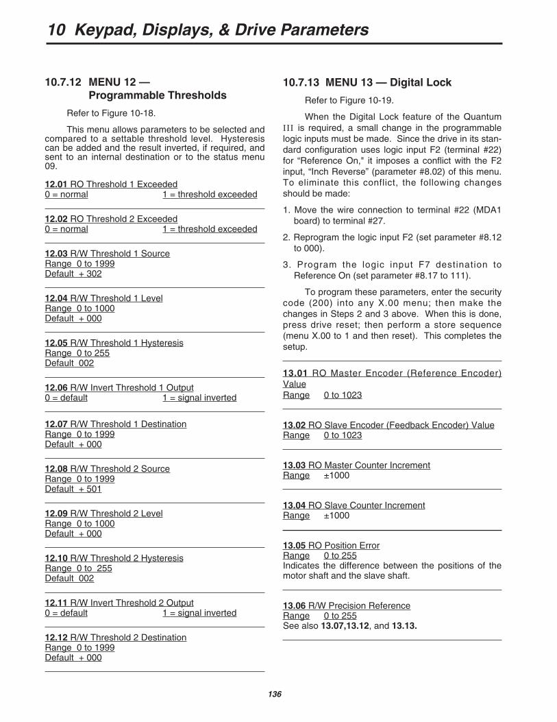
10 Keypad, Displays, & Drive Parameters
136
10.7.12 MENU 12 — Programmable Thresholds
Refer to Figure 10-18.
This menu allows parameters to be selected andcompared to a settable threshold level. Hysteresiscan be added and the result inverted, if required, andsent to an internal destination or to the status menu09.
12.01 RO Threshold 1 Exceeded0 = normal 1 = threshold exceeded
12.02 RO Threshold 2 Exceeded0 = normal 1 = threshold exceeded
12.03 R/W Threshold 1 SourceRange 0 to 1999Default + 302
12.04 R/W Threshold 1 LevelRange 0 to 1000Default + 000
12.05 R/W Threshold 1 HysteresisRange 0 to 255Default 002
12.06 R/W Invert Threshold 1 Output0 = default 1 = signal inverted
12.07 R/W Threshold 1 DestinationRange 0 to 1999Default + 000
12.08 R/W Threshold 2 SourceRange 0 to 1999Default + 501
12.09 R/W Threshold 2 LevelRange 0 to 1000Default + 000
12.10 R/W Threshold 2 HysteresisRange 0 to 255Default 002
12.11 R/W Invert Threshold 2 Output0 = default 1 = signal inverted
12.12 R/W Threshold 2 DestinationRange 0 to 1999Default + 000
10.7.13 MENU 13 — Digital Lock
Refer to Figure 10-19.
When the Digital Lock feature of the QuantumIII is required, a small change in the programmablelogic inputs must be made. Since the drive in its stan-dard configuration uses logic input F2 (terminal #22)for “Reference On," it imposes a conflict with the F2input, “Inch Reverse” (parameter #8.02) of this menu.To eliminate this conflict, the following changesshould be made:
1. Move the wire connection to terminal #22 (MDA1board) to terminal #27.
2. Reprogram the logic input F2 (set parameter #8.12to 000).
3. Program the logic input F7 destination toReference On (set parameter #8.17 to 111).
To program these parameters, enter the securitycode (200) into any X.00 menu; then make thechanges in Steps 2 and 3 above. When this is done,press drive reset; then perform a store sequence(menu X.00 to 1 and then reset). This completes thesetup.
13.01 RO Master Encoder (Reference Encoder)ValueRange 0 to 1023
13.02 RO Slave Encoder (Feedback Encoder) ValueRange 0 to 1023
13.03 RO Master Counter IncrementRange ±1000
13.04 RO Slave Counter IncrementRange ±1000
13.05 RO Position ErrorRange 0 to 255Indicates the difference between the positions of themotor shaft and the slave shaft.
13.06 R/W Precision ReferenceRange 0 to 255See also 13.07,13.12, and 13.13.
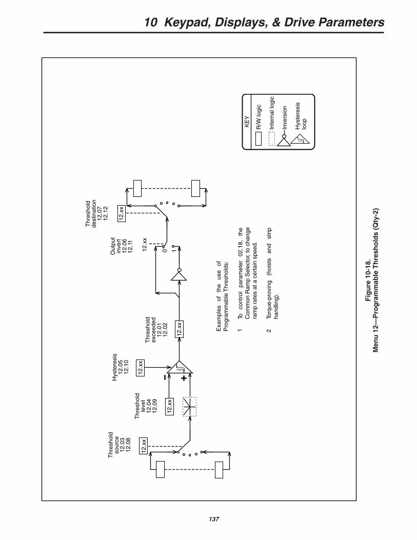
10 Keypad, Displays, & Drive Parameters
137
Fig
ure
10-
18.
Men
u 1
2—P
rog
ram
mab
le T
hre
sho
lds
(Qty
-2)
0 1
12.x
x
Thr
esho
ldso
urce
12.0
312
.08
Thr
esho
ldle
vel
12.0
412
.09
Out
put
inve
rt12
.06
12.1
1
Thr
esho
ldde
stin
atio
n12
.07
12.1
2
Thr
esho
ldex
ceed
ed12
.01
12.0
2
12.x
x
12.x
x
12.x
x
12.x
x
To
cont
rol
para
met
er
02.1
8,
the
Com
mon
Ram
p S
elec
tor,
to c
hang
e ra
mp
rate
s at
a c
erta
in s
peed
.
Torq
ue-p
rovi
ng
(hoi
sts
and
strip
ha
ndlin
g).
Exa
mpl
es
of
the
use
of
Pro
gram
mab
le T
hres
hold
s:
∫∫
12.x
x
Hys
tere
sis
12.0
512
.10
R/W
logi
c
Inte
rnal
logi
c
Inve
rsio
n
Hys
tere
sis
loopKE
Y
∫∫
1 2
10 Keypad, Displays, & Drive Parameters
138
13.07 R/W Precision ReferenceRange 0 to 255See also 13.06,13.12, and 13.13.Parameters 13.06 and 13.07 are used, in conjunctionwith each other, to define a 16-bit velocity referencewhen parameter 13.12 = 0.
Parameter 13.06 is the least-significant component.
Parameter 13.07 is the most-significant compo-nent.
Each unit of 13.07 represents 256 increments of 13.06.
13.08 R/W Precision Loop Gain
Range 0 to 255Determines the amount of velocity correction per unitof position error. The setting thus determines howquickly the loop responds to a disturbance, and thusaffects the motor output shaft position.This parameter must be adjusted in conjunction withthe Speed Loop PID Gains 03.09, 03.10 and 03.11 toattain the best balance between stability and quickresponse.
13.09 R/W Position Loop Correction LimitRange 0 to 1000Limits the amount of the velocity-correction resultingfrom a position error.
13.10 R/W Position Loop Software Enable0 = disabled 1 = enabledEnables the Position Loop software.
13.11 R/W Rigid Lock Enable0 = disabled 1 = enabledWhen 13.11 = 1, the position error, relative to the timethe position loop is closed, is always absolute.Therefore, if the slave output shaft is slowed down byan overload, position is regained by an automaticspeed increase when the load reduces to or belowmaximum.When 13.11 = 0 (default), the Position Loop is closedonly when the “At Speed” condition is reached. Thisallows the accelerating ramps to be used withoutoverspeeding the slave output shaft.
13.12 R/W Reference Source1 = master encoder 0 = precision referenceDetermines the source of the digital loop reference, asbetween the master encoder (13.01) or the precisionreferences (13.06 and 13.07).
13.13 R/W Precision Reference Latch0 = use last values 1 = use updated valuesThe two Precision Reference values, 13.06 and13.07, cannot be changed simultaneously. To pre-vent the Position Loop reading inconsistent valuesduring the change, parameter 13.13 = 0 (default)enables the Position Loop to continue to use the lastvalues while the change is occurring. When a changeof both 13.06 and 13.07 has been completed, setting13.13 = 0 causes the updated values to be applied.13.13 should then be reset to 0, ready for the nextupdate.
13.14 R/W Precision Speed Reference (16-bit)Range 000 to 65,535This parameter is a “wide integer” equivalent to thePrecision Reference 13.06 and 13.07. It allows theprecision reference to be written as a single state-ment, removing the need for the latch, parameter13.13.
Parameter 13.14 is intended mainly for use through serial communications.

10 Keypad, Displays, & Drive Parameters
139
R/W
logi
c
R/O
logi
c
Inte
rnal
logi
c
KE
Y
13.0
1
Mas
ter
Enc
oder
(Ref
eren
ce)
13.0
3
Mas
ter
coun
ter
incr
emen
t
07.2
4
Sca
ling
07.0
5
Spe
edre
fere
nce
inpu
t
01
07.2
5
Ref
eren
ceen
code
rse
lect
or
13.1
2
Ref
eren
ceso
urce
1
0 x 64
01
13.1
3P
reci
sion
refe
renc
ela
tch
(13.
07 x
256
) +
13.
06P
reci
sion
refe
renc
es
+ +
01
08.2
1D
isab
le n
orm
allo
gic
func
tions
0 1
F2
inpu
tin
ch r
ev.
x (-
1)
01.0
50
108.0
3F
3 in
put
inch
fwd.
Inch
ref
eren
ce
Ref
eren
ce O
N 0
1.11
INC
H s
elec
tor
01.1
3
Har
d sp
eed
ref.
sele
ctor
03.
19
Ram
p ou
tput
ref
. sel
ecto
r 03
.21
Pos
ition
sof
twar
e en
able
13.
10
At s
peed
10.
07
Rig
id lo
ck e
nabl
e 13
.11
&
&x
(-1)
01.1
2
Rev
erse
sele
ctor
01
1
0E
PO
S13
.05
Pos
ition
erro
r0 1
13.0
8
Pos
ition
gain
03.1
8
0 1
13.1
0
01.1
8
0 103
.02
+-
+
0 1
03.1
2
Dig
ital f
eedb
ack
sele
ctor
13.0
503
.14
Pos
ition
gain
13.0
2
Sla
ve E
ncod
er(F
eedb
ack)
Spe
edfe
edba
ck
Pos
ition
softw
are
enab
le
13.0
9
Cor
rect
ion
limit
08.0
2
Spe
edco
rrec
tion
Spe
edfe
ed fw
d
13.1
4O
R
Fig
ure
10-
19.
Men
u 1
3—D
igit
al L
ock
13.0
4
Enc
oder
Sca
ling
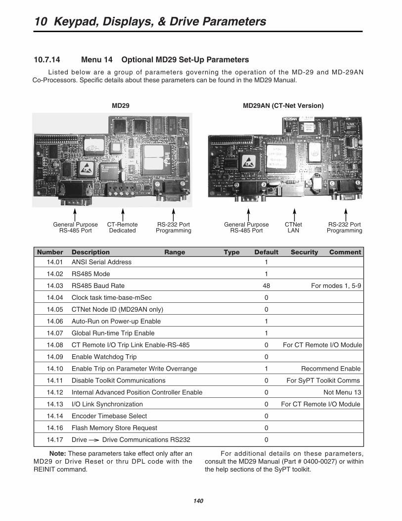
10 Keypad, Displays, & Drive Parameters
140
Number Description Range Type Default Security Comment
14.01 ANSI Serial Address 1
14.02 RS485 Mode 1
14.03 RS485 Baud Rate 48 For modes 1, 5-9
14.04 Clock task time-base-mSec 0
14.05 CTNet Node ID (MD29AN only) 0
14.06 Auto-Run on Power-up Enable 1
14.07 Global Run-time Trip Enable 1
14.08 CT Remote I/O Trip Link Enable-RS-485 0 For CT Remote I/O Module
14.09 Enable Watchdog Trip 0
14.10 Enable Trip on Parameter Write Overrange 1 Recommend Enable
14.11 Disable Toolkit Communications 0 For SyPT Toolkit Comms
14.12 Internal Advanced Position Controller Enable 0 Not Menu 13
14.13 I/O Link Synchronization 0 For CT Remote I/O Module
14.14 Encoder Timebase Select 0
14.16 Flash Memory Store Request 0
14.17 Drive —> Drive Communications RS232 0
10.7.14 Menu 14 Optional MD29 Set-Up Parameters
MD29 MD29AN (CT-Net Version)
General Purpose CT-Remote RS-232 PortRS-485 Port Dedicated Programming
Note: These parameters take effect only after anMD29 or Drive Reset or thru DPL code with theREINIT command.
For additional details on these parameters, consult the MD29 Manual (Part # 0400-0027) or withinthe help sections of the SyPT toolkit.
General Purpose CTNet RS-232 PortRS-485 Port LAN Programming
Listed below are a group of parameters governing the operation of the MD-29 and MD-29ANCo-Processors. Specific details about these parameters can be found in the MD29 Manual.

10 Keypad, Displays, & Drive Parameters
141
Number Description Range Type Default Security Comment
15.01 RO variable 1 ±1999 RO None
15.02 RO variable 2 ±1999 RO None
15.03 RO variable 3 ±1999 RO None
15.04 RO variable 4 ±1999 RO None
15.05 RO variable 5 ±1999 RO None
15.06 Real R/W variable 1 ±1999 R/W + 000 Level 1
15.07 Real R/W variable 2 ±1999 R/W + 000 Level 1
15.08 Real R/W variable 3 ±1999 R/W + 000 Level 1
15.09 Real R/W variable 4 ±1999 R/W + 000 Level 1
15.10 Real R/W variable 5 ±1999 R/W + 000 Level 1
15.11 Integer R/W variable 1 0 to 255 R/W 000 Level 1
15.12 Integer R/W variable 2 0 to 255 R/W 000 Level 1
15.13 Integer R/W variable 3 0 to 255 R/W 000 Level 1
15.14 Integer R/W variable 4 0 to 255 R/W 000 Level 1
15.15 Integer R/W variable 5 0 to 255 R/W 000 Level 1
15.16 Integer R/W variable 6 0 to 255 R/W 000 Level 1
15.17 Integer R/W variable 7 0 to 255 R/W 000 Level 1 See 15.60
15.18 Integer R/W variable 8 0 to 255 R/W 000 Level 1 and 15.61
15.19 Integer R/W variable 9 0 to 255 R/W 000 Level 1
15.20 Integer R/W variable 10 0 to 255 R/W 000 Level 1
15.21 Bit variable 1 0 or 1 R/W 0 Level 1
15.22 Bit variable 2 0 or 1 R/W 0 Level 1
15.23 Bit variable 3 0 or 1 R/W 0 Level 1
15.24 Bit variable 4 0 or 1 R/W 0 Level 1
15.25 Bit variable 5 0 or 1 R/W 0 Level 1
15.26 Bit variable 6 0 or 1 R/W 0 Level 1
15.27 Bit variable 7 0 or 1 R/W 0 Level 1
15.28 Bit variable 8 0 or 1 R/W 0 Level 1
15.29 Bit variable 9 0 or 1 R/W 0 Level 1
15.30 Bit variable 10 0 or 1 R/W 0 Level 1
15.31 Bit variable 11 0 or 1 R/W 0 Level 1
15.32 Bit variable 12 0 or 1 R/W 0 Level 1
15.33 Bit variable 13 0 or 1 R/W 0 Level 1
10.7.15 MENU 15 — Optional Application Menu 1
For parameter values, please refer to the following list.
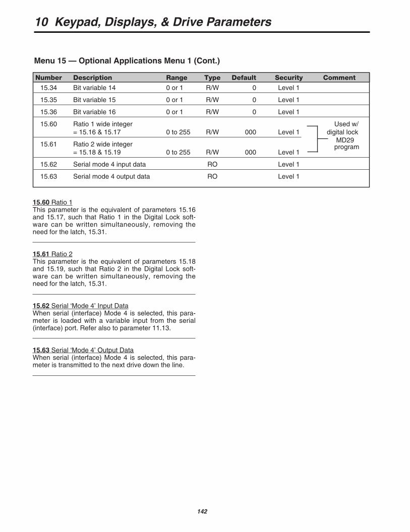
10 Keypad, Displays, & Drive Parameters
142
Number Description Range Type Default Security Comment
15.34 Bit variable 14 0 or 1 R/W 0 Level 1
15.35 Bit variable 15 0 or 1 R/W 0 Level 1
15.36 Bit variable 16 0 or 1 R/W 0 Level 1
15.60 Ratio 1 wide integer Used w/ = 15.16 & 15.17 0 to 255 R/W 000 Level 1 digital lock
15.61 Ratio 2 wide integer MD29
= 15.18 & 15.19 0 to 255 R/W 000 Level 1program
15.62 Serial mode 4 input data RO Level 1
15.63 Serial mode 4 output data RO Level 1
Menu 15 — Optional Applications Menu 1 (Cont.)
15.60 Ratio 1This parameter is the equivalent of parameters 15.16and 15.17, such that Ratio 1 in the Digital Lock soft-ware can be written simultaneously, removing theneed for the latch, 15.31.
15.61 Ratio 2This parameter is the equivalent of parameters 15.18and 15.19, such that Ratio 2 in the Digital Lock soft-ware can be written simultaneously, removing theneed for the latch, 15.31.
15.62 Serial ‘Mode 4’ Input DataWhen serial (interface) Mode 4 is selected, this para-meter is loaded with a variable input from the serial(interface) port. Refer also to parameter 11.13.
15.63 Serial ‘Mode 4’ Output DataWhen serial (interface) Mode 4 is selected, this para-meter is transmitted to the next drive down the line.
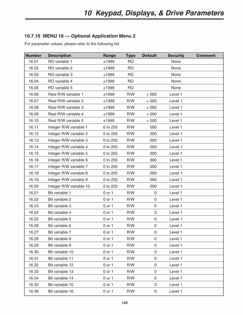
10 Keypad, Displays, & Drive Parameters
143
Number Description Range Type Default Security Comment
16.01 RO variable 1 ±1999 RO None
16.02 RO variable 2 ±1999 RO None
16.03 RO variable 3 ±1999 RO None
16.04 RO variable 4 ±1999 RO None
16.05 RO variable 5 ±1999 RO None
16.06 Real R/W variable 1 ±1999 R/W + 000 Level 1
16.07 Real R/W variable 2 ±1999 R/W + 000 Level 1
16.08 Real R/W variable 3 ±1999 R/W + 000 Level 1
16.09 Real R/W variable 4 ±1999 R/W + 000 Level 1
16.10 Real R/W variable 5 ±1999 R/W + 000 Level 1
16.11 Integer R/W variable 1 0 to 255 R/W 000 Level 1
16.12 Integer R/W variable 2 0 to 255 R/W 000 Level 1
16.13 Integer R/W variable 3 0 to 255 R/W 000 Level 1
16.14 Integer R/W variable 4 0 to 255 R/W 000 Level 1
16.15 Integer R/W variable 5 0 to 255 R/W 000 Level 1
16.16 Integer R/W variable 6 0 to 255 R/W 000 Level 1
16.17 Integer R/W variable 7 0 to 255 R/W 000 Level 1
16.18 Integer R/W variable 8 0 to 255 R/W 000 Level 1
16.19 Integer R/W variable 9 0 to 255 R/W 000 Level 1
16.20 Integer R/W variable 10 0 to 255 R/W 000 Level 1
16.21 Bit variable 1 0 or 1 R/W 0 Level 1
16.22 Bit variable 2 0 or 1 R/W 0 Level 1
16.23 Bit variable 3 0 or 1 R/W 0 Level 1
16.24 Bit variable 4 0 or 1 R/W 0 Level 1
16.25 Bit variable 5 0 or 1 R/W 0 Level 1
16.26 Bit variable 6 0 or 1 R/W 0 Level 1
16.27 Bit variable 7 0 or 1 R/W 0 Level 1
16.28 Bit variable 8 0 or 1 R/W 0 Level 1
16.29 Bit variable 9 0 or 1 R/W 0 Level 1
16.30 Bit variable 10 0 or 1 R/W 0 Level 1
16.31 Bit variable 11 0 or 1 R/W 0 Level 1
16.32 Bit variable 12 0 or 1 R/W 0 Level 1
16.33 Bit variable 13 0 or 1 R/W 0 Level 1
16.34 Bit variable 14 0 or 1 R/W 0 Level 1
16.35 Bit variable 15 0 or 1 R/W 0 Level 1
16.36 Bit variable 16 0 or 1 R/W 0 Level 1
10.7.16 MENU 16 — Optional Application Menu 2
For parameter values, please refer to the following list.

10 Keypad, Displays, & Drive Parameters
144