Embed Size (px)
Citation preview
8/10/2019 Quarry Operation
http://slidepdf.com/reader/full/quarry-operation 1/20
THE CEMENT FACTORY
2. QUARRY OPERATION

8/10/2019 Quarry Operation
http://slidepdf.com/reader/full/quarry-operation 2/20
8/10/2019 Quarry Operation
http://slidepdf.com/reader/full/quarry-operation 3/20
The Cement factory
2. Quarry Operation
Page 2.1
QUARRY OPERATION
Table of Contents
2 Quarry Operation.........................................................................................3
2.1 Quarry Operation .....................................................................................3
2.2 Raw material deposits ..............................................................................3
2.3 Evolution of deposit .................................................................................4
2.4 Prospecting and evaluation of deposit .....................................................4
2.5 Computer-examination.............................................................................6
2.6 Simultaneous quarrying ...........................................................................6
2.7 Removal of overburden............................................................................72.8 Quarrying of soft raw materials .............................................................10
2.9 Quarrying of hard stone .........................................................................11
2.10 Rock drilling machine............................................................................15
2.11 Transport machinery ..............................................................................16
2.12 Selection of Machinery ..........................................................................17
8/10/2019 Quarry Operation
http://slidepdf.com/reader/full/quarry-operation 4/20
The Cement factory
2. Quarry Operation
Page 2.2
Table of Figures
Figure 2-1 ..................................................................................................................... 4
Figure 2-2 ..................................................................................................................... 4
Figure 2-3 ..................................................................................................................... 5
Figure 2-4 ..................................................................................................................... 5
Figure 2-5 ..................................................................................................................... 6Figure 2-6 ..................................................................................................................... 7
Figure 2-7 ..................................................................................................................... 7
Figure 2-8 ..................................................................................................................... 8
Figure 2-9 Figure 2-10 ...........................................................................................9
Figure 2-11 ...................................................................................................................9
Figure 2-12 .................................................................................................................10
Figure 2-13 .................................................................................................................10
Figure 2-14 .................................................................................................................11
Figure 2-15 Figure 2-16 .....................................................................................11Figure 2-17 .................................................................................................................13
Figure 2-18 .................................................................................................................13
Figure 2-19 .................................................................................................................14
Figure 2-20 .................................................................................................................14
Figure 2-21 .................................................................................................................15
Figure 2-22 .................................................................................................................15
Figure 2-23 .................................................................................................................16
Figure 2-24 .................................................................................................................17
8/10/2019 Quarry Operation
http://slidepdf.com/reader/full/quarry-operation 5/20
The Cement factory
2. Quarry Operation
Page 2.3
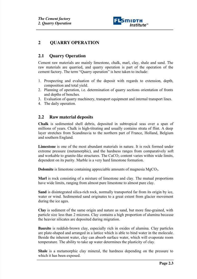
2 QUARRY OPERATION
2.1 Quarry Operation
Cement raw materials are mainly limestone, chalk, marl, clay, shale and sand. The
raw materials are quarried, and quarry operation is part of the operation of the
cement factory. The term “Quarry operation” is here taken to include:
1. Prospecting and evaluation of the deposit with regards to extension, depth,
composition and total yield.
2. Planning of operation, i.e. determination of quarry sections orientation of fronts
and depths of benches.
3.
Evaluation of quarry machinery, transport equipment and internal transport lines.4. The daily operation.
2.2 Raw material deposits
Chalk is sedimented shell debris, deposited in subtropical seas over a span of
millions of years. Chalk is high-titrating and usually contains strata of flint. A deep
layer stretches from Scandinavia to the northern part of France, Holland, Belgium
and southern England.
Limestone is one of the most abundant materials in nature. It is rock formed under extreme pressure (metamorphic), and the hardness ranges from comparatively soft
and workable to granite-like structures. The CaCO3 content varies within wide limits,
dependent on its purity. Marble is a very hard limestone formation.
Dolomite is limestone containing appreciable amounts of magnesia MgCO3.
Marl is rock consisting of a mixture of limestone and clay. The mutual proportions
have wide limits, ranging from almost pure limestone to almost pure clay.
Sand is disintegrated silica-rich rock, normally transported far from its origin by ice,
water or wind. Sedimented sand originates to a great extent from glacier movementduring the ice ages.
Clay is sediment of the same origin and nature as sand, but more fine-grained, with
particle size less than 2 microns. Clay contains a high proportion of alumina because
the heavier silicates are deposited during migration.
Bauxite is reddish-brown clay, especially rich in oxides of alumina. Clay particles
are plate-shaped and arranged in a lattice which is able to bind water in the molecule.
Beside the inherent water, clay can absorb surface water, which will evaporate room
temperature. The ability to take up water determines the plasticity of clay.
Shale is a metamorphic clay mineral, the hardness depending on the pressure to
which it has been exposed.
8/10/2019 Quarry Operation
http://slidepdf.com/reader/full/quarry-operation 6/20
The Cement factory
2. Quarry Operation
Page 2.4
Sandstone consists of closely knitted particles of clay and sand, and the proportions
between the two components may vary.
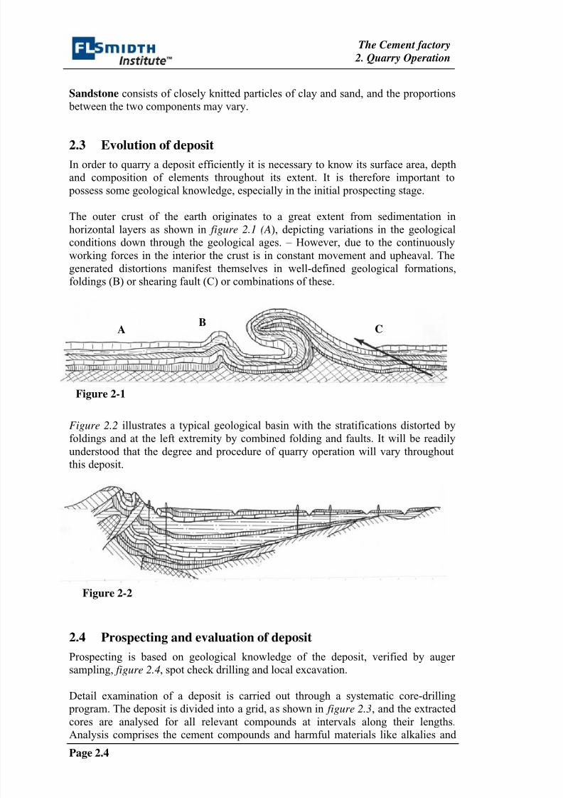
2.3
Evolution of deposit
In order to quarry a deposit efficiently it is necessary to know its surface area, depth
and composition of elements throughout its extent. It is therefore important to
possess some geological knowledge, especially in the initial prospecting stage.
The outer crust of the earth originates to a great extent from sedimentation in
horizontal layers as shown in figure 2.1 (A), depicting variations in the geological
conditions down through the geological ages. – However, due to the continuously
working forces in the interior the crust is in constant movement and upheaval. The
generated distortions manifest themselves in well-defined geological formations,
foldings (B) or shearing fault (C) or combinations of these.
Figure 2-1
Figure 2.2 illustrates a typical geological basin with the stratifications distorted by
foldings and at the left extremity by combined folding and faults. It will be readily
understood that the degree and procedure of quarry operation will vary throughout
this deposit.
Figure 2-2
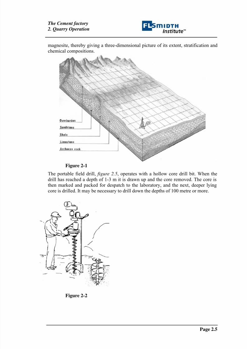
2.4 Prospecting and evaluation of deposit
Prospecting is based on geological knowledge of the deposit, verified by auger
sampling, figure 2.4, spot check drilling and local excavation.
Detail examination of a deposit is carried out through a systematic core-drilling program. The deposit is divided into a grid, as shown in figure 2.3, and the extracted
cores are analysed for all relevant compounds at intervals along their lengths.
Analysis comprises the cement compounds and harmful materials like alkalies and
AB
C
8/10/2019 Quarry Operation
http://slidepdf.com/reader/full/quarry-operation 7/20
The Cement factory
2. Quarry Operation
Page 2.5
magnesite, thereby giving a three-dimensional picture of its extent, stratification and
chemical compositions.
Figure 2-1
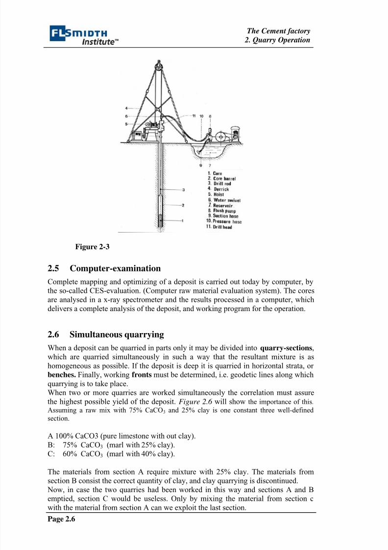
The portable field drill, figure 2.5, operates with a hollow core drill bit. When the
drill has reached a depth of 1-3 m it is drawn up and the core removed. The core is
then marked and packed for despatch to the laboratory, and the next, deeper lyingcore is drilled. It may be necessary to drill down the depths of 100 metre or more.
Figure 2-2
8/10/2019 Quarry Operation
http://slidepdf.com/reader/full/quarry-operation 8/20
The Cement factory
2. Quarry Operation
Page 2.6
Figure 2-3
2.5 Computer-examination
Complete mapping and optimizing of a deposit is carried out today by computer, by
the so-called CES-evaluation. (Computer raw material evaluation system). The coresare analysed in a x-ray spectrometer and the results processed in a computer, which
delivers a complete analysis of the deposit, and working program for the operation.
2.6 Simultaneous quarrying
When a deposit can be quarried in parts only it may be divided into quarry-sections,
which are quarried simultaneously in such a way that the resultant mixture is as
homogeneous as possible. If the deposit is deep it is quarried in horizontal strata, or
benches. Finally, working fronts must be determined, i.e. geodetic lines along which
quarrying is to take place.When two or more quarries are worked simultaneously the correlation must assure
the highest possible yield of the deposit. Figure 2.6 will show the importance of this.
Assuming a raw mix with 75% CaCO3 and 25% clay is one constant three well-defined
section.
A 100% CaCO3 (pure limestone with out clay).
B: 75% CaCO3 (marl with 25% clay).
C: 60% CaCO3 (marl with 40% clay).
The materials from section A require mixture with 25% clay. The materials from
section B consist the correct quantity of clay, and clay quarrying is discontinued. Now, in case the two quarries had been worked in this way and sections A and B
emptied, section C would be useless. Only by mixing the material from section c
with the material from section A can we exploit the last section.
8/10/2019 Quarry Operation
http://slidepdf.com/reader/full/quarry-operation 9/20
The Cement factory
2. Quarry Operation
Page 2.7
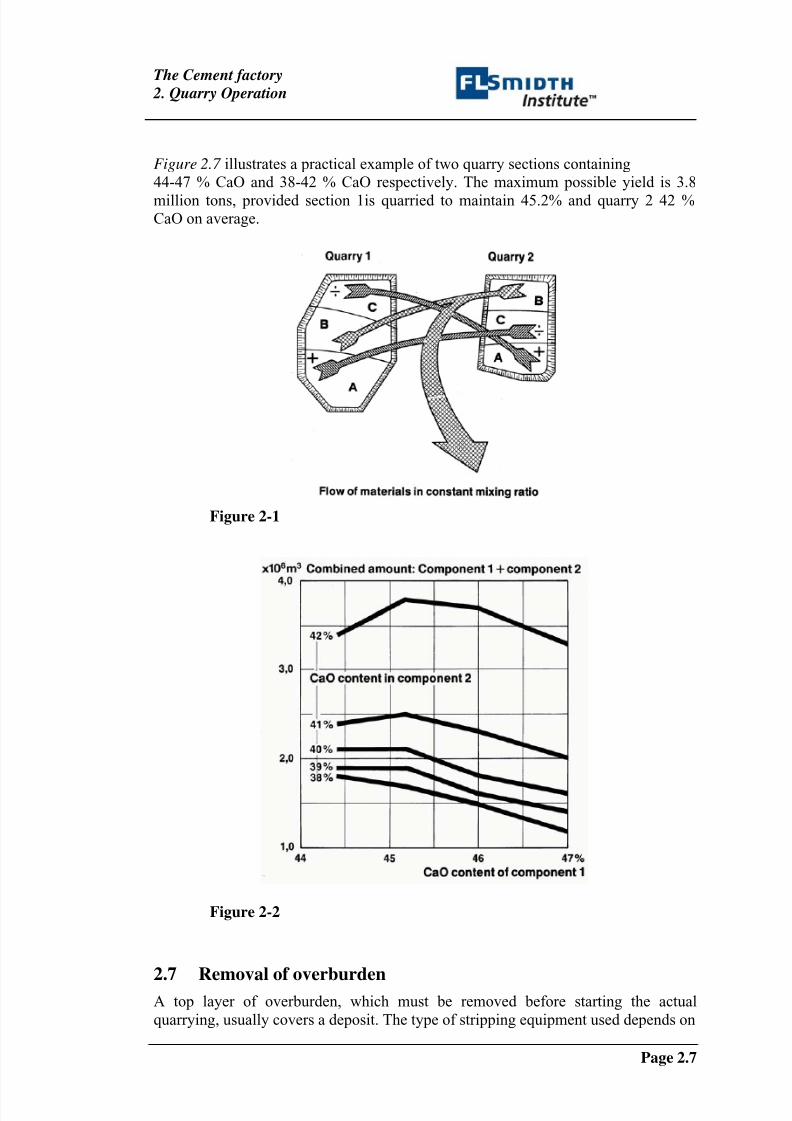
Figure 2.7 illustrates a practical example of two quarry sections containing
44-47 % CaO and 38-42 % CaO respectively. The maximum possible yield is 3.8
million tons, provided section 1is quarried to maintain 45.2% and quarry 2 42 %CaO on average.
Figure 2-1
Figure 2-2
2.7
Removal of overburdenA top layer of overburden, which must be removed before starting the actual
quarrying, usually covers a deposit. The type of stripping equipment used depends on
8/10/2019 Quarry Operation
http://slidepdf.com/reader/full/quarry-operation 10/20
The Cement factory
2. Quarry Operation
Page 2.8
the depth and nature of the overburden and of the underlying surface, as well as on
the transport distance.
Bulldozers are well suited for work on wet, slippery overburden and on overburden
with stones and roots. The bulldozer is a rugged pushing machine with large wheels
or caterpillar tracks. Units on tracks are more mobile in rough terrain whereas units
on wheels have the advantage of speed. With a high bench with slowly advancing
front the overburden maybe pushed ahead of the front by bulldozers, or they may pile
overburden for subsequent removal by front-end loader, power shovel or dragline.
The ripper is used for breaking up hard, compact and stony soil. It is a large tractor
weighing up to 30 tons and powered by a 400 hp engine. It has a bulldozer blade in
front and a ripper outfit with 1-5 shanks in the rear, which can plough through the top
soil layer to a depth of 1 meter. When the area is ripped the tractor treats the
loosened material in the same way as a bulldozer.
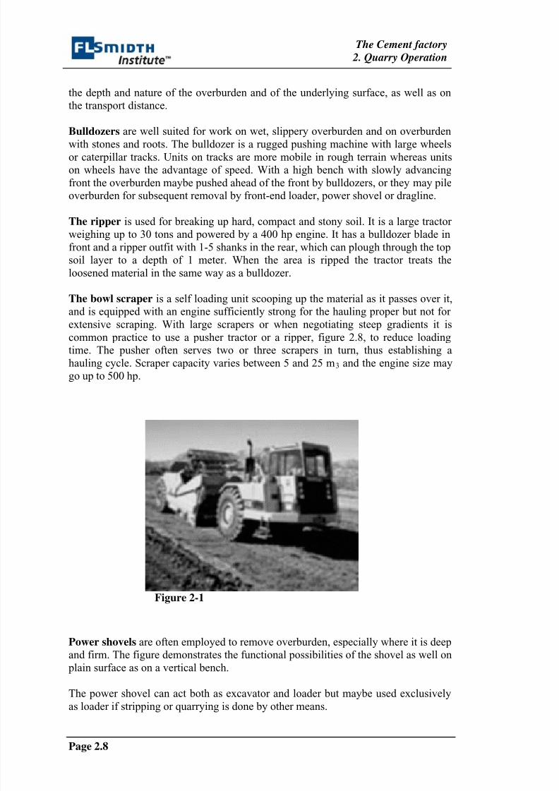
The bowl scraper is a self loading unit scooping up the material as it passes over it,
and is equipped with an engine sufficiently strong for the hauling proper but not for
extensive scraping. With large scrapers or when negotiating steep gradients it is
common practice to use a pusher tractor or a ripper, figure 2.8, to reduce loading
time. The pusher often serves two or three scrapers in turn, thus establishing a
hauling cycle. Scraper capacity varies between 5 and 25 m3 and the engine size may
go up to 500 hp.
Figure 2-1
Power shovels are often employed to remove overburden, especially where it is deep
and firm. The figure demonstrates the functional possibilities of the shovel as well on
plain surface as on a vertical bench.
The power shovel can act both as excavator and loader but maybe used exclusivelyas loader if stripping or quarrying is done by other means.
8/10/2019 Quarry Operation
http://slidepdf.com/reader/full/quarry-operation 11/20
The Cement factory
2. Quarry Operation
Page 2.9
Figure 2-2 Figure 2-3
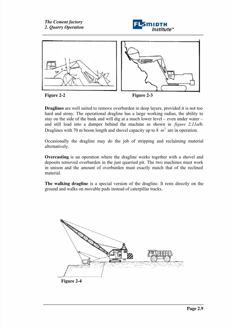
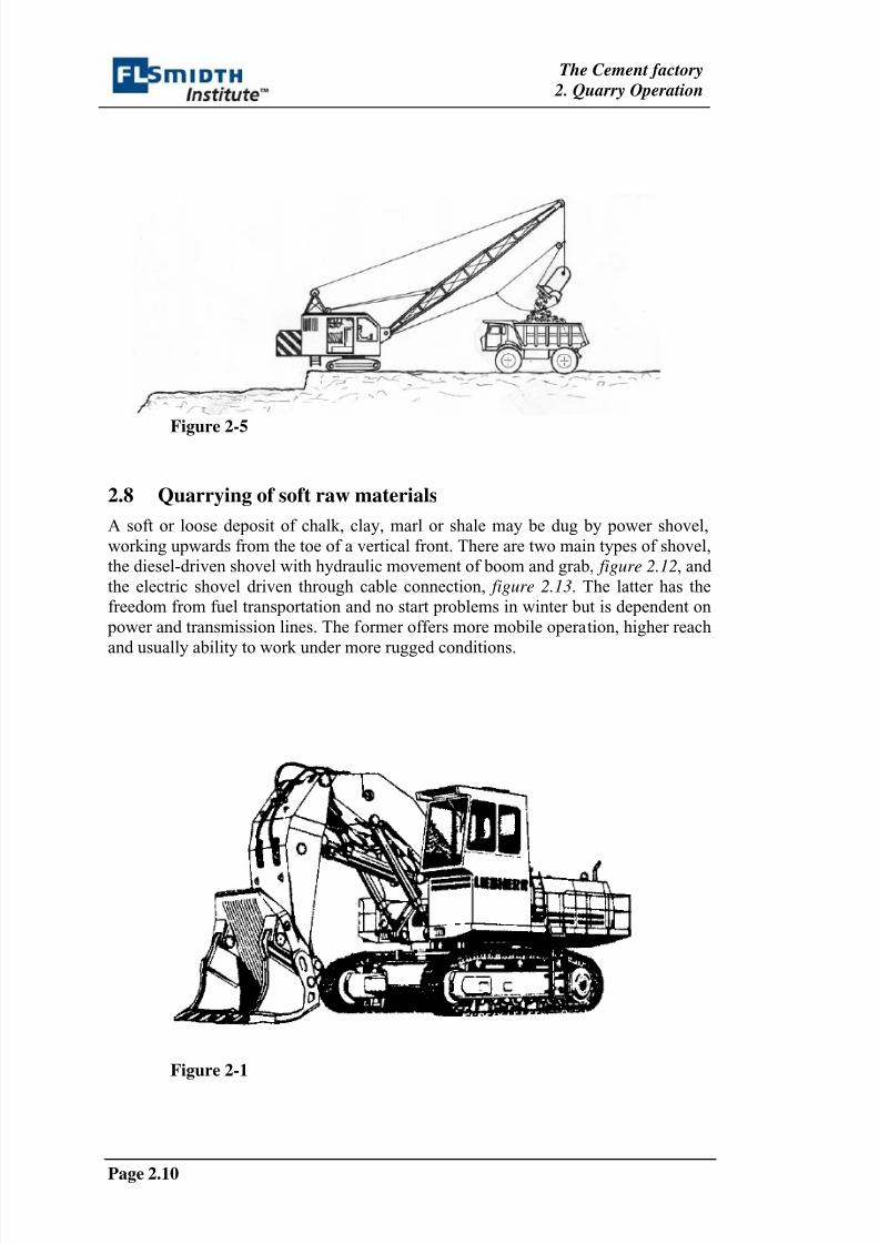
Draglines are well suited to remove overburden in deep layers, provided it is not too
hard and stony. The operational dragline has a large working radius, the ability tostay on the side of the bank and will dig at a much lower level – even under water –
and still load into a dumper behind the machine as shown in figure 2.11a/b.
Draglines with 70 m boom length and shovel capacity up to 8 3m are in operation.
Occasionally the dragline may do the job of stripping and reclaiming material
alternatively.
Overcasting is an operation where the dragline works together with a shovel and
deposits removed overburden in the just quarried pit. The two machines must work
in unison and the amount of overburden must exactly match that of the reclined
material.
The walking dragline is a special version of the dragline. It rests directly on the
ground and walks on movable pads instead of caterpillar tracks.
Figure 2-4
8/10/2019 Quarry Operation
http://slidepdf.com/reader/full/quarry-operation 12/20
The Cement factory
2. Quarry Operation
Page 2.10
Figure 2-5
2.8 Quarrying of soft raw materials
A soft or loose deposit of chalk, clay, marl or shale may be dug by power shovel,
working upwards from the toe of a vertical front. There are two main types of shovel,
the diesel-driven shovel with hydraulic movement of boom and grab, figure 2.12, and
the electric shovel driven through cable connection, figure 2.13. The latter has the
freedom from fuel transportation and no start problems in winter but is dependent on
power and transmission lines. The former offers more mobile operation, higher reach
and usually ability to work under more rugged conditions.
Figure 2-1
8/10/2019 Quarry Operation
http://slidepdf.com/reader/full/quarry-operation 13/20
The Cement factory
2. Quarry Operation
Page 2.11
Figure 2-2
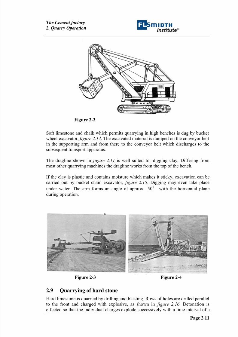
Soft limestone and chalk which permits quarrying in high benches is dug by bucket
wheel excavator, figure 2.14. The excavated material is dumped on the conveyor belt
in the supporting arm and from there to the conveyor belt which discharges to the
subsequent transport apparatus.
The dragline shown in figure 2.11 is well suited for digging clay. Differing from
most other quarrying machines the dragline works from the top of the bench.
If the clay is plastic and contains moisture which makes it sticky, excavation can becarried out by bucket chain excavator, figure 2.15. Digging may even take place
under water. The arm forms an angle of approx. 050 with the horizontal plane
during operation.
Figure 2-3 Figure 2-4
2.9 Quarrying of hard stone
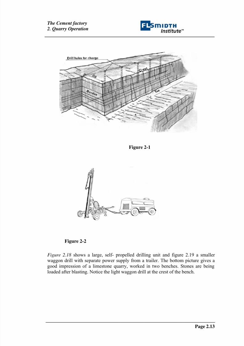
Hard limestone is quarried by drilling and blasting. Rows of holes are drilled parallel
to the front and charged with explosive, as shown in figure 2.16 . Detonation is
effected so that the individual charges explode successively with a time interval of a
8/10/2019 Quarry Operation
http://slidepdf.com/reader/full/quarry-operation 14/20
The Cement factory
2. Quarry Operation
Page 2.12
few milliseconds whereby the pressure wave from each detonation causes a
secondary shattering effect. This method improves fragmenting of the stones.
Drilling is done by rotary drill or by percussion drill or by a combination of both.
The drill may be operated by compressed air from diesel driven or electrically driven
compressors, or hydraulically operated from diesel driven or electrically driven
pumps.
A drilling method, down-hole drilling, uses a special percussion tool, fitted to drill
rod of the machine. It is convenient when a hole has to be collared in hard rock or for
inclined drilling.
Handhold drills are the simplest and smallest aggregates. They are used for
example to drill for selective blasting, for drilling in local veins and for secondary
blasting of blocks.
Waggon drills with separate power supply are used for medium sized quarries
working with benches. The drill rig can be wheel or crawler- mounted and will drill
up to depths of 10 – 20 m with drill hole diameters up to 100 mm. Figure 2.17 shows
a light waggon drill with separate compressor.
Self-propelled drilling machines carrying power supply and drill rig in one unite
operate mainly in large quarries with heavy beds. They are capable of drilling to
depths of 20-30 m with coupled drill rods, with diameters up to 200 mm, and they
produce anything between 3000 to 5000 tonnes per machine shift. Most machines of
this type are crawler-mounted, and down-hole drilling is becoming increasingly popular.
8/10/2019 Quarry Operation
http://slidepdf.com/reader/full/quarry-operation 15/20
The Cement factory
2. Quarry Operation
Page 2.13
Figure 2-1
Figure 2-2
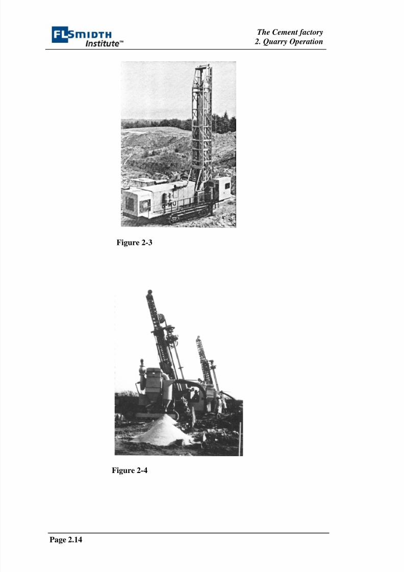
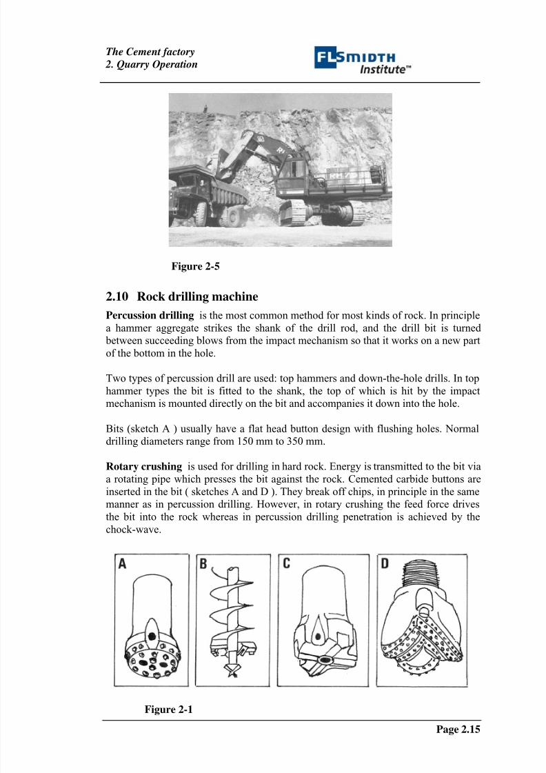
Figure 2.18 shows a large, self- propelled drilling unit and figure 2.19 a smaller
waggon drill with separate power supply from a trailer. The bottom picture gives a
good impression of a limestone quarry, worked in two benches. Stones are being
loaded after blasting. Notice the light waggon drill at the crest of the bench.
8/10/2019 Quarry Operation
http://slidepdf.com/reader/full/quarry-operation 16/20
The Cement factory
2. Quarry Operation
Page 2.14
Figure 2-3
Figure 2-4
8/10/2019 Quarry Operation
http://slidepdf.com/reader/full/quarry-operation 17/20
The Cement factory
2. Quarry Operation
Page 2.15
Figure 2-5
2.10 Rock drilling machine
Percussion drilling is the most common method for most kinds of rock. In principle
a hammer aggregate strikes the shank of the drill rod, and the drill bit is turned
between succeeding blows from the impact mechanism so that it works on a new part
of the bottom in the hole.
Two types of percussion drill are used: top hammers and down-the-hole drills. In top
hammer types the bit is fitted to the shank, the top of which is hit by the impact
mechanism is mounted directly on the bit and accompanies it down into the hole.
Bits (sketch A ) usually have a flat head button design with flushing holes. Normal
drilling diameters range from 150 mm to 350 mm.
Rotary crushing is used for drilling in hard rock. Energy is transmitted to the bit via
a rotating pipe which presses the bit against the rock. Cemented carbide buttons are
inserted in the bit ( sketches A and D ). They break off chips, in principle in the same
manner as in percussion drilling. However, in rotary crushing the feed force drives
the bit into the rock whereas in percussion drilling penetration is achieved by the
chock-wave.
Figure 2-1
8/10/2019 Quarry Operation
http://slidepdf.com/reader/full/quarry-operation 18/20
The Cement factory
2. Quarry Operation
Page 2.16
Rotary drilling is used mainly for drilling in soft rock. Most bit types use tungsten
carbide cross-face inserted cutters ( sketch C ). Drilling diameters go up to 400 mm,
and penetration ranges from 16 to 35 metres per hour in soft deposits and 6-8 metres
per hour in hard rock.
Flushing is essential to keep the bottom of the hole clean during drilling. Cuttings
are removed by flushing with air or water which is forced down through a flushing
hole in the drill rod and flushing channels in the bit. The mixture of cuttings and
flushing medium is forced out of the drill hole through the space between rod and
wall.
2.11 Transport machinery
Large sized stone is taken to the crusher by dumper or by rail. If the finishing crusher
is installed at the quarry the material leaving the quarry is small enough in size to be
taken to the factory by conveyor belt. The topography may occasionally favour arope cable-way, but its transport capacity is limited.
Shovels are widely used for loading material onto dumpers. They have shovel
capacities ranging from 1 to 10 m3 and engines up to 200 hp.
Front-end loaders often substitute shovels. They are more mobile and maybe used
as combined loader and hauler over short distance. But their loading capacities are
less and they are less sturdy than shovels. Such loaders are sometimes crawler-
mounted but most often on wheel to increase their mobility.
Figure 2-1
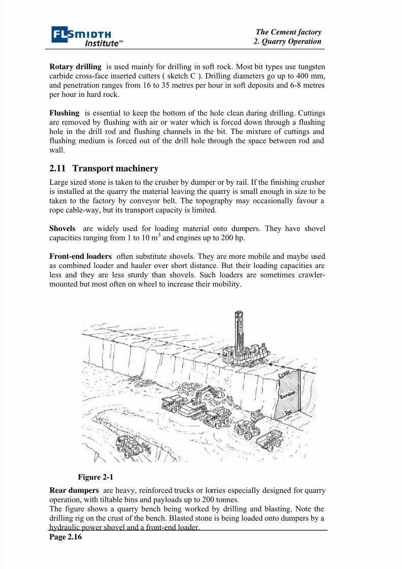
Rear dumpers are heavy, reinforced trucks or lorries especially designed for quarry
operation, with tiltable bins and payloads up to 200 tonnes.The figure shows a quarry bench being worked by drilling and blasting. Note the
drilling rig on the crust of the bench. Blasted stone is being loaded onto dumpers by a
hydraulic power shovel and a front-end loader.
8/10/2019 Quarry Operation
http://slidepdf.com/reader/full/quarry-operation 19/20
The Cement factory
2. Quarry Operation
Page 2.17
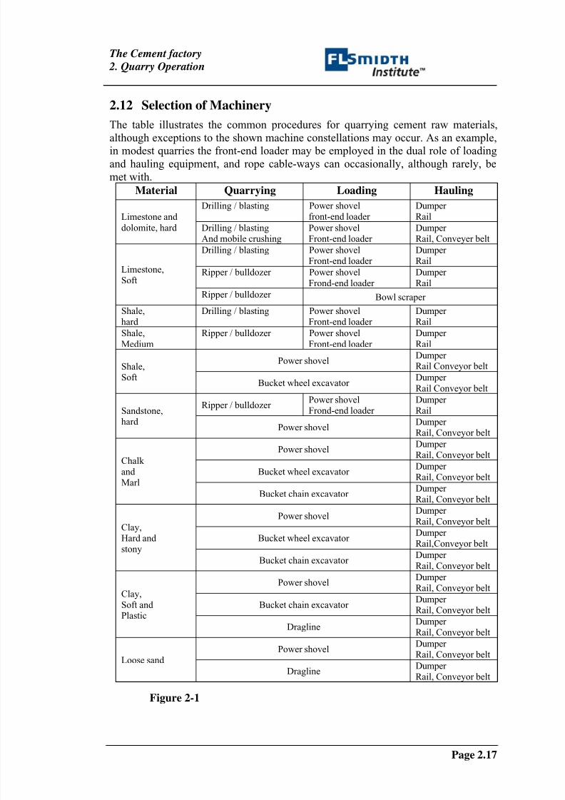
2.12 Selection of Machinery
The table illustrates the common procedures for quarrying cement raw materials,
although exceptions to the shown machine constellations may occur. As an example,in modest quarries the front-end loader may be employed in the dual role of loading
and hauling equipment, and rope cable-ways can occasionally, although rarely, be
met with.
Material Quarrying Loading Hauling
Drilling / blasting Power shovelfront-end loader
Dumper RailLimestone and
dolomite, hard Drilling / blastingAnd mobile crushing
Power shovelFront-end loader
Dumper Rail, Conveyer belt
Drilling / blasting Power shovelFront-end loader
Dumper Rail
Ripper / bulldozer Power shovel
Frond-end loader
Dumper
Rail
Limestone,
SoftRipper / bulldozer Bowl scraper
Shale,hard
Drilling / blasting Power shovelFront-end loader
Dumper Rail
Shale,
Medium
Ripper / bulldozer Power shovel
Front-end loader
Dumper
Rail
Power shovelDumper Rail Conveyor beltShale,
SoftBucket wheel excavator
Dumper
Rail Conveyor belt
Ripper / bulldozer Power shovelFrond-end loader
Dumper RailSandstone,
hard Power shovel Dumper Rail, Conveyor belt
Power shovelDumper Rail, Conveyor belt
Bucket wheel excavator Dumper Rail, Conveyor belt
Chalk
and Marl
Bucket chain excavator Dumper Rail, Conveyor belt
Power shovelDumper
Rail, Conveyor belt
Bucket wheel excavator Dumper Rail,Conveyor belt
Clay,Hard and stony
Bucket chain excavator Dumper
Rail, Conveyor belt
Power shovelDumper Rail, Conveyor belt
Bucket chain excavator Dumper Rail, Conveyor belt
Clay,
Soft and Plastic
DraglineDumper Rail, Conveyor belt
Power shovelDumper Rail, Conveyor belt
Loose sand
DraglineDumper Rail, Conveyor belt
Figure 2-1

8/10/2019 Quarry Operation
http://slidepdf.com/reader/full/quarry-operation 20/20
The Cement factory
2. Quarry Operation