Embed Size (px)
Citation preview
Transport Expert
VePAL TX150EHandheld SDH/PDH Test Set
SDH network testing simplifiedVeEX™ VePAL TX150E is a next generation test solution for SDH/PDH networks transporting legacy and next generation services.
Transport Expert
SDH FUNCTIONS
OPERATING MODESTerminated modeMonitor modeIntrusive Through mode ▪ Modification of selected SOH bytes ▪ Alarm Generation and Error Insertion of selected defects and anomalies respectivelyNon-Intrusive Through mode ▪ Pass entire signal through without modification of section and line overhead bytes
SIGNAL STRUCTURESTM-1 (VC-n container equipped with); ▪ Framed or unframed PDH test pattern (per ITU-T 0.150)STM-4 (VC-n container equipped with); ▪ Framed or unframed PDH test pattern (per ITU-T 0.150) ▪ Bulk TSS (per ITU-T 0.181)STM-16 (VC-n container equipped with); ▪ Framed or unframed PDH test pattern (per ITU-T 0.150) ▪ Bulk TSS (per ITU-T 0.181)
MAPPINGS (According to ITU-T G.707)C-12 (unstructured or framed E1, asynchronous or byte synchronous)C-3 (unstructured or framed E3 or DS3) via AU-3 or AU-4C-4 (unstructured or framed E4)C-4-4c (STM-4 and STM-16)C-4-16c (STM-16)
OptionalC-11 (unstructured or framed DS1)
PATTERNSThe following test patterns can be generated:▪ PRBS: 211-1, 215-1, 220-1, 223-1, 231-1: normal or inverted▪ Fixed: 0000, 1111, 1010, 1000 and 1100▪ User programmable word: user defined up to 24 bits
ERRORSInsertion of; ▪ FAS, B1, B2, MS-REI, B3, HP-REI, LP-REI, LP-BIP, slips and bit errorsInsertion mode: ▪ Single and rate (1 x 10⁻³ to 5 x 10⁻⁶)Detection of; ▪ FAS, B1, B2, MS-REI, B3, HP-REI, LP-BIP, LP-REI, and bit errors
ALARMSGeneration of; ▪ LOS, LOF, MS-AIS, MS-RDI, RS-TIM, AU-LOP, AU-AIS, HP-UNEQ, HP-PLM, HP-RDI, HP-TIM, TU-LOM, TU-LOP, TU-AIS, LP-UNEQ, LP-PLM, LP-RDI, LP-RFI, LP-TIM, 2M AIS, 2M LOF, 2M RDIInsertion mode: Static (Enable/Disable)Monitoring and simultaneous detection of; ▪ LOS, LOF, OOF, RS-TIM, MS-AIS, MS-RDI, AU-AIS, AU-LOP, HP- UNEQ, HP-PLM, HP-TIM, HP-RDI, TU-LOM, TU-AIS, TU-LOP, LP- UNEQ, LP-PLM, LP-TIM, LP-RDI, LP-RFI
AUTOMATIC CONFIGURATIONConfigures tester to the incoming signal – Bit rate, framing, line coding and test pattern per ITU-T G.707, G.703, 0.151 and 0.181 recommendations where applicable
OVERHEAD ANALYSIS AND GENERATIONNetwork Architectures supported ▪ Linear (per G.783) or Ring (per G.841)
Analysis – Decode and display; SOH/POH bytes in hexadecimal, binary or ASCII formats; ▪ S1 synchronization status ▪ C2 HP signal label ▪ J0 trace identifier (16 bytes) in ASCII format ▪ J1 trace identifier (16 or 64 bytes) in ASCII format ▪ J2 trace identifier (16 or 64 bytes) in ASCII format ▪ K1, K2 APS Control ▪ V5 LP signal label
Generation - Programmable BytesRSOH: ▪ J0 trace: 1 byte hexadecimal or 16 byte ASCII sequence with CRC-7
MSOH: ▪ K1, K2 APS bytes per ITU-T G.783 and G.841 ▪ S1 synchronization status message
HO-POH (VC-4, VC-3): ▪ J1 trace: 16 byte ASCII with CRC-7 or 64 byte ASCII sequence ▪ C2 signal label ▪ H4 Sequence / Mutiframe Indicator ▪ G1 (bit 5) – End to end path status (RDI generation) ▪ K3 (bits 1-4) APS signaling
LO-POH (VC-3): ▪ J1 trace: 16 byte ASCII with CRC-7 or 64 byte ASCII sequence ▪ C2 signal label ▪ G1 (bit 5) – End to end path status (RDI generation) ▪ K3 (bits 1-4) APS signaling
LO-POH (VC-12, VC-11): ▪ V5 (bits 5-7) LP signal label ▪ J2 trace: 16 byte ASCII with CRC-7 or 64 byte ASCII sequence ▪ K4 (bits 3-4) LP APS signaling
OVERHEAD BERT:▪ Generation and analysis of PRBS pattern in DCC channels (D1-D3 or D4-D12 bytes) or E1, E2, F1, N1 and N2 bytes▪ PRBS: 223 -1, 220 -1, 215 -1, 211 -1 (inverted or non inverted)▪ Bit error counter, rate and errored seconds
POINTER ANALYSIS/GENERATIONAnalysis ▪ Current value, Increments, decrements, sum, difference ▪ New Data Flags (NDF) ▪ Tributary frequency offset (ppm of AU/TU)
Generation ▪ Single pointer, increment, decrement, or increment / decrement ▪ Programming of SS bits
TRIBUTARY SCANAutomatically scan VC-12s for errors, alarms and events using sequential BER
Transport Expert
PDH FUNCTIONS OPERATING MODESTerminated modeMonitor modeIntrusive Thru mode (E1 only)Bridge (E1 only, DS1 Optional)
SIGNAL STRUCTURE2,048 Mbit/s (E1) ▪ Unframed or Framed with/without CRC per ITU-T G.704 (PCM30, PCM30C, PCM31, PCM31C) ▪ Test signal in N/M x 64 kbit/s where N=1 to 30 34,368 Mbit/s (E3) ▪ Unframed or Framed according to ITU-T G.751
Optional 1,544 Mbit/s (DS1) ▪ Unframed or Framed SF (D4), ESF per ANSI and Telcordia standards where applicable ▪ Test signal in N x 64 kbit/s, N x 56 kbit/s where N=1 to 24 44,736 Mbit/s (DS3) ▪ Unframed or Framed M13 and C-Bit Parity per ITU-T G.752 or ITU-T G.704 139,264 Mbit/s (E4) ▪ Unframed or Framed according to ITU-T G.751
PATTERNSThe following test patterns can be generated:▪ PRBS: 211-1, 215-1, 220-1, 223-1, 231-1: normal or inverted▪ Fixed: 0000, 1111, 1010, 1000 and 1100▪ User programmable word: user defined up to 24 bits
ERRORSInsertion; ▪ 2,048 Mbit/s (E1): Code, FAS, CRC, EBIT, Bit errors ▪ 34,368 Mbit/s (E3): Code, FAS, 2M FAS, 2M, Bit errors ▪ Single or continuous rate (1 x 10⁻³ to 5 x 10⁻⁶)
Optional ▪ 1,544 Mbit/s (DS1): Code, FAS, Bit, Frame, CRC ▪ 44,736 Mbit/s (DS3): Code, FAS, MFAS, P/C-Parity, Bit errors ▪ 139,264 Mbit/s (E4): Code, FAS, Bit errors
Measurement: ▪ 2,048 Mbit/s (E1): Code, FAS, CRC, E-BIT and Bit errors ▪ 34,368 Mbit/s (E3): Code, FAS, Bit errors
Optional (DS1, DS3 and E4) – where applicable ▪ Code, FAS, MFAS, 2M CRC, P/C-Parity, Bit errors
ALARMSGeneration: ▪ 2,048 Mbit/s (E1): LOS, AIS, LOF, RDI ▪ 34,368 Mbit/s (E3): LOS, AIS, LOF, RDI, 2M LOF, 2M RDI ▪ Mode: Static (Enable/Disable)
Optional ▪ 1,544 Mbit/s (DS1): AIS, yellow, idle, LOS, LOF ▪ 44,736 Mbit/s (DS3): LOS, LOF, OOF, AIS, Parity ▪ 139,264 Mbit/s (E4): AIS, FAS RDI
Measurement: ▪ 2,048 Mbit/s (E1): LOS, AIS, LOF, LOMF, RDI and LSS ▪ 34,368 Mbit/s (E3): LOS, AIS, LOF, RDI and LSS
Optional (T-Carrier DS1/DS3) ▪ LOS, AIS, LOF, OOF, IDLE, YELLOW and LSS
MEASUREMENT FUNCTIONS
TEST RESULTSError count, ES, %ES, SES, %SES, UAS, %UAS, EFS, %EFS, AS, %AS, and rate for all events: errors, alarms and pointer events
PERFORMANCE ANALYSISMeasurements according to:▪ ITU-T G.821 recommendation: ES, EFS, SES, DM, and UAS with HRP 1% to 100%▪ ITU-T G.826 recommendation: EB, BBE, ES, EFS, SES, UAS. HRP of 1% to 100%. ▪ In service measurement (ISM) using B1, B2, B3, FAS, CRC or Code (E1). ▪ Out of service measurement (OOS) using bit errors (TSE)▪ ITU-T G.828 recommendation: ES, EFS, SES, BBE, SEP, UAS with HRP 1% to 100%▪ ITU-T G.829 recommendation: ES, EFS, SES, BBE, UAS on RSOH (B1), MSOH (B2) or TSE▪ ITU-T M.2100 recommendation: ES, EFS, SES, UAS with HRP 1% to 100%. ▪ User defined thresholds for Maintenance (MTCE) and Bringing into Service (BIS) objectives.▪ ITU-T M.2101 recommendation: ES, EFS, SES, BBE, SEP, UAS with HRP 1% to 100%. ▪ User defined thresholds for Maintenance (MTCE) and Bringing into Service (BIS) objectives. In service measurements on both near and far ends of path using TSE, HP-BIP (B3), MS-BIP (B2), RS-BIP (B1) and LP-BIP (V5)
COMMON FUNCTIONS AND MEASUREMENTS
AUTO CONFIGURATIONAvailable on all interfaces:Identification of received signal - instrument configuration based on network type, bit rate, line coding, framing, mapping, and test pattern
FREQUENCY MEASUREMENT▪ Optical & Electrical Interfaces: Hz & bit/s in ppm ▪ Resolution: 1Hz▪ TIE measurement on Pointer Justification Events
ROUND TRIP DELAYAvailable on all interfaces and mappings:▪ Measurement Range: 1μS to 10 seconds▪ Resolution: ±1μs or 1 U.I.
EVENT LOGGINGDate and time stamped events in tabular format
HISTOGRAMSAvailable for all interfaces▪ Display of Errors and Alarms versus time ▪ Resolution: Seconds, minutes, hours and days
LED INDICATORS▪ Fixed LEDs for Signal, Framing, Pattern and Errors/Alarms▪ Soft LEDs for SDH/PDH Alarms/Errors displaying historical events and conditions.
▪ Intuitive presentation of measurements with test graphics▪ High resolution color touch-screen viewable in any lighting conditions fitted with protective cover▪ Robust, handheld chassis packed with powerful and flexible features for demanding environments and test conditions▪ Optimized for field engineers or technicians installing and maintaining SDH networks transporting legacy and next generation Ethernet services▪ Ethernet port and connection for back office applications, workforce management and triple play service verification▪ User defined test profiles and thresholds enable fast, efficient and consistent turn-up of services▪ USB memory stick support and FTP upload capability for test result storage and file transfer respectively▪ Maintain instrument software, manage test configurations, process measurement results and generate customer test reports using included ReVeal™ PC software▪ Extend field testing time using interchangeable LiIon battery pack/s. Greater battery autonomy provided in standby mode▪ Supports advanced IP testing; Ping, trace route, ARP Wiz, VoIP, IPTV, WiFi, web browser, and FTP upload/download via Ethernet or USB port where applicable▪ Perform remote testing and monitoring using the remote control option via standard Ethernet interface
▪ PDH testing at E1, E3 bit rates. DS1, DS3 and E4 (Optional)▪ Balanced (120Ω) and Unbalanced (75Ω) interfaces for E1▪ Dual E1 Receivers for bi-directional monitoring▪ Full Rate E1 and Fractional N, M x64 kbit/s testing ▪ PDH Analysis with Sa bit Generation▪ Non intrusive Pulse Mask Analysis at E1, E3 and DS3 bit rates▪ SDH testing at STM-1, STM-4 and STM-16 bit rates ▪ Flexible wavelength/bit rate options using industry standard SFPs conforming to the Multi Source Agreement (MSA) ▪ Optical Power, Level and Frequency measurements▪ Auto Configuration of network type, bit rate, line coding, framing, mapping, and test pattern▪ Payload Mapping according to ITU-T G.707 recommendations ▪ Concatenated Payloads▪ Bit Error and Performance Analysis per ITU standards▪ Error and Alarm Generation and Analysis▪ Path Trace Generation and Analysis▪ Pointer Generation and Analysis ▪ Automatic Protection Switching/Service Disruption testing▪ Histogram and Event analysis for errors and alarms▪ Round Trip Delay on all interfaces and payload mappings▪ Transmit Frequency Offset to stress clock recovery circuits▪ Section and Path Overhead Monitoring and Byte decoding ▪ Tandem Connection Monitoring
Platform Highlights Key Features
SPECIFICATIONS
ELECTRICAL INTERFACESDual RJ-48 (120 ohm balanced)
Rates and line code:
▪ 1,544 Mbit/s, AMI & B8ZS (Optional)
▪ 2,048 Mbit/s , HDB3 & AMI
BNC (75 ohm unbalanced)
Rates and line code:
▪ 2,048 Mbit/s, HDB3 & AMI
▪ 34,368 Mbit/s, HDB3
▪ 44,736 Mbit/s, B3ZS (Optional)
▪ 139,264 Mbit/s, CMI (Optional)
▪ 155,520 Mbit/s, CMI (Optional)
Compliant to ITU-T G.703, G.823, G.824, G.825, G.772 and ANSI T1.102 recommendations where applicable
Clock recovery (pulling range) per ITU-T G.703
Receiver Sensitivity:
For 2.048 Mbit/s (E1);
▪ Terminate: ≤ 6dB (cable loss)
▪ Monitor (PMP): ≤ 26dB (20dB resistive, 6dB cable loss)
▪ Bridge: ≤ 6dB (cable loss)
For 34,368 Mbit/s (E3);
▪ Terminate: ≤ 12dB (cable loss)
▪ Monitor (PMP): ≤ 26dB (20dB resistive, 6dB cable loss)
Optional
For 1.544 Mbit/s (DS1);
▪ Terminate: ≤ 6dB (cable loss)
▪ Monitor (PMP): ≤ 26dB (20dB resistive, 6dB cable loss)
▪ Bridge mode: ≤ 6dB (cable loss)
For 44,736 Mbit/s (DS3);
▪ Terminate: ≤ 6dB (cable loss)
▪ Monitor (PMP): ≤ 26dB (20dB resistive, 6dB cable loss)
For 139,264 Mbit/s (E4) and 155,520 Mbit/s (STM-1E);
▪ Terminate: ≤ 12.7dB (cable loss)
▪ Monitor (PMP): ≤ 26dB (20dB resistive, 6dB cable loss)
CLOCK SYNCHRONIZATIONInternal: 2,048Mbit/s, ± 3.5 ppm stability per ITU-T G.812
Recovered: 2,048 Mbit/s from the incoming signal
External reference via SMA connector
▪ Clock: 2,048 MHz (sine wave or TTL)
▪ Signal: 2,048 Mbit/s (HDB3)
Tx Frequency Offset:
▪ Up to 25,000 ppm in steps of 0.1 ppm for both optical
and electrical interfaces
OPTICAL INTERFACESSmall Form Factor Pluggable (SFP) transceivers compatible with Multi Source Agreement (MSA)
ROHS compliant and Lead Free per Directive 2002/95/EC
Operating temperature range: -10˚C to 70˚C
Safety: Class 1, per FDA/CDRH, EN (IEC) 60825 eye safety and EN (IEC) 60950 electrical safety regulations
Compliant to ITU-T G.957 – Optical interfaces and systems relating to SDH (VeEX supplied SFPs only)
Optical Power Measurement: ± 2dB accuracy, 1dB resolution (VeEX supplied SFPs only)
SFP optical transceiver selection table (Refer to ordering options)
Optical option 301-01-004G 301-01-005G 301-01-006G 301-01-007G 301-01-008G 301-01-009G
Wavelength (nm) 1310 1310 1550 1310 1310 1550
Range (km) 15 40 80 15 40 80
Line rate (Mbps) Up to 622 Up to 622 Up to 622 Up to 2488 Up to 2488 Up to 2488
Connector LC duplex LC duplex LC duplex LC duplex LC duplex LC duplex
Line coding NRZ NRZ NRZ NRZ NRZ NRZ
Laser type Fabry Perot DFB DFB DFB DFB DFB
Wavelength range (nm) 1274 to 1356 1280 to 1335 1480 to 1580 1270 to 1360 1280 to 1335 1500 to 1580
Spectral w idth (nm) 2.5 1 1 1 1 1
Output pow er (dBm) -15 to -8 -3 to +2 -3 to +2 -5 to 0 -2 to +3 -2 to +3
Detector type PIN PIN PIN PIN APD APDSensitivity (dBm)@ 155 Mbps@ 622 Mbps@ 2.488 Gbps
-28 to -8-28 to -8
N/A
-28 to -8-28 to -8
N/A
-28 to -8-28 to -8
N/A
-23 to -10-22 to 0-18 to 0
-30 to -15-29 to -9-27 to -9
-30 to -15-29 to -9-28 to -9
Wavelength range (nm) 1260 to 1600 1260 to 1600 1260 to 1600 1270 to 1600 1270 to 1600 1270 to 1600
STM-1/4/16 (155/622/2488 Mbps)Specifications
Tran
smitt
erRe
ceiv
erGe
nera
l
STM-1/4 (155/622 Mbps)
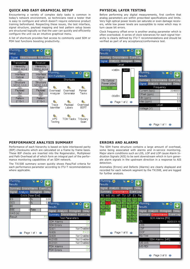
ERRORS AND ALARMSThe SDH frame structure contains a large amount of overhead, some being associated with alarms and in-service monitoring. Major alarm conditions such as LOS, LOF and LOP cause Alarm In-dication Signals (AIS) to be sent downstream which in turn gener-ate alarm signals in the upstream direction in a response to AIS detection.
Anomalies (Errors) and Defects (Alarms) are clearly displayed and recorded for each network segment by the TX150E, and are logged for further analysis.
PERFORMANCE ANALYSIS SUMMARYPerformance of each hierarchy is based on byte interleaved parity (BIP) checksums which are calculated on a frame by frame basis. These BIP checks are inserted into the Regenerator, Multiplexer and Path Overhead all of which form an integral part of the perfor-mance monitoring capabilities of an SDH network.
The TX150E summary screen quickly shows Pass/Fail criteria for each performance parameter according to ITU-T recommendations where applicable.
QUICK AND EASY GRAPHICAL SETUPEncountering a variety of complex daily tasks is common in today’s network environment, so technicians need a tester that is easy to configure and which doesn’t require extensive product training beforehand. Respecting these issues, the test interface, signal structure, payload mapping and test pattern setup boxes are structured logically so that the user can quickly and efficiently configure the unit via an intuitive graphical menu.
A list of shortcuts provides fast access to commonly used SDH or PDH test functions boosting productivity.
PHYSICAL LAYER TESTINGBefore performing any digital measurements, first confirm that analog parameters are within prescribed specifications and limits. Very high optical power levels can saturate or even damage receiv-ers, while low power levels are susceptible to noise which may in turn cause bit errors.
Clock frequency offset error is another analog parameter which is often overlooked. A series of clock tolerances for each signal hier-archy is clearly defined by ITU-T recommendations and should be verified as part of any acceptance/conformance test.
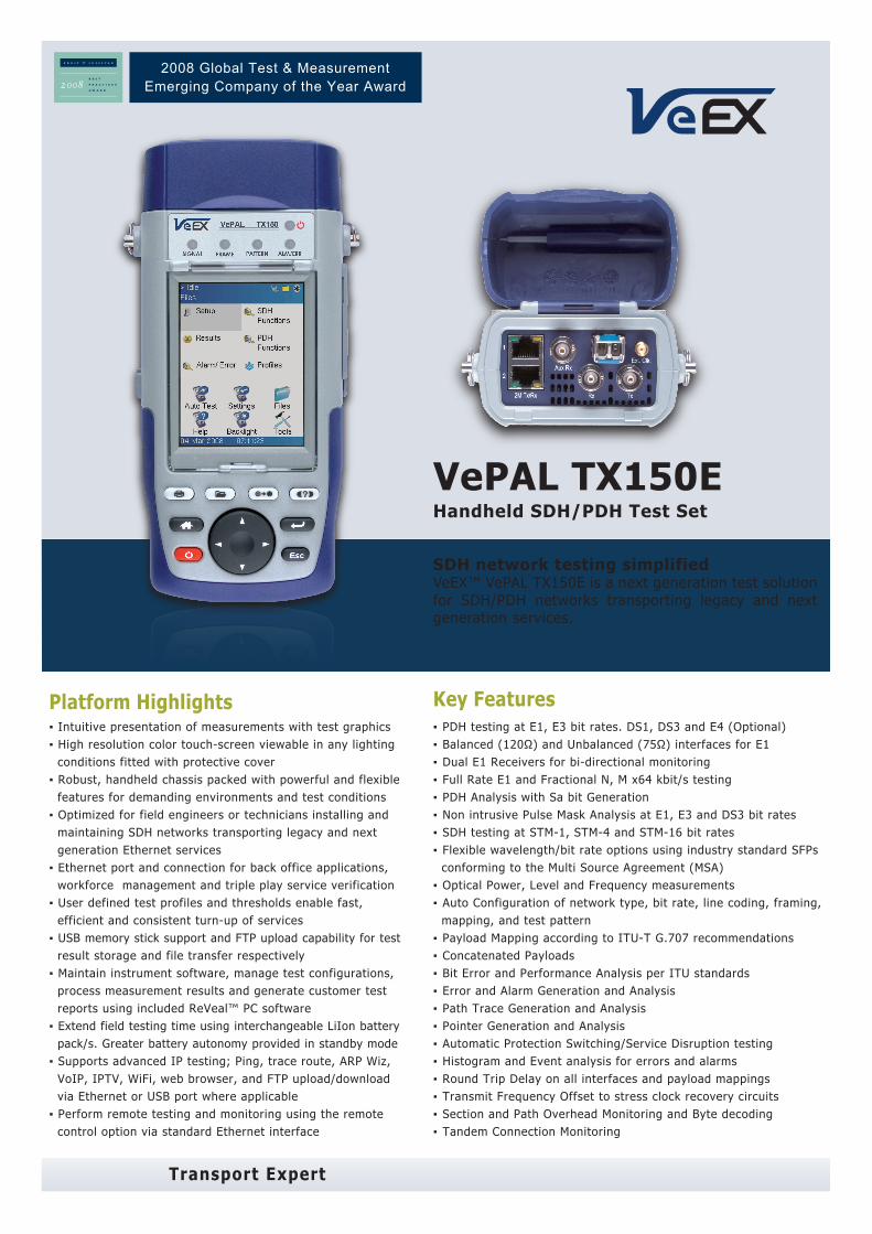
APPLICATIONSInstallation, commissioning, monitoring and maintenance of SDH and PDH networks simplified thanks to a combination of intuitive features and powerful test functions. When multiplexing several low order tributaries together, SDH signals are often compromised by various impair-ments in the process. Defining the type of anomaly or defect is crucial in isolating the network element or signal path causing the problem and reducing costly network downtime. Fast troubleshooting and comprehensive analysis of transmission problems can be performed using intrusive, non-intrusive and monitoring test modes. Novice users will benefit from the easy-to-use Auto-configuration and Tributary Scan test modes, while experienced users will appreciate the array of advanced features such as Overhead Monitoring and Byte Control, Pointer Test Sequences, Path Trace generation, Tandem Connection Monitoring and lots more.
OUT OF SERVICE TESTING
Applications include;
▪ End-to-end BERT
▪ Tributary Mapping/de-Mapping
▪ Path/Section Trace Generation
▪ Bringing Into Service (M.2100)
▪ Pulse mask analysis (E1/E3/DS3)
▪ Mux Testing
▪ Round Trip Delay (RTD)
SDH TerminalMultiplexer
SDH TerminalMultiplexer
Regenerator RegeneratorSDH CrossConnect
Path
MultiplexerSection
MultiplexerSection
Regenerator Section
Regenerator Section
Regenerator Section
TributarySignals
TributarySignals
VCAssembly
VCAssembly
DWDM SDH Optical Ring
ADM ADM
ADM
ADM
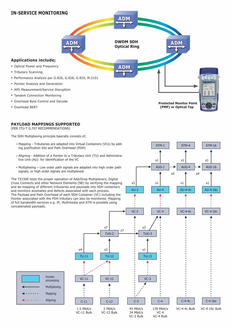
Applications include;▪ Optical Power and Frequency
▪ Tributary Scanning
▪ Performance Analysis per G.826, G.828, G.829, M.2101
▪ Pointer Analysis and Generation
▪ APS Measurement/Service Disruption
▪ Tandem Connection Monitoring
▪ Overhead Byte Control and Decode
▪ Overhead BERT
x3
x1
x7x7
x4 x3 x1
x1 x1
x1 x1
x4x4
x1
x3
STM-1 STM-4 STM-16
AU-3 AU-4 AU-4-4c AU-4-16c
AUG-1 AUG-4 AUG-16
VC-3 VC-4 VC-4-4c VC-4-16c
TUG-2 TUG-3
TU-12
VC-12
TU-11
VC-11
TU-13
VC-3
C-4-4c C-4-16cC-12 C-3 C-4C-11
1.5 Mbit/sVC-11 Bulk
2 Mbit/sVC-12 Bulk
45 Mbit/s34 Mbit/sVC-3 Bulk
139 Mbit/sVC-4
VC-4 Bulk
VC-4-4c Bulk VC-4-16c Bulk
PAYLOAD MAPPINGS SUPPORTED(PER ITU-T G.707 RECOMMENDATIONS)
The SDH Multiplexing principle basically consists of; ▪ Mapping - Tributaries are adapted into Virtual Containers (VCs) by add- ing justification bits and Path Overhead (POH) ▪ Aligning - Addition of a Pointer to a Tributary Unit (TU) and Administra- tive Unit (AU) for identification of the VC ▪ Multiplexing – Low order path signals are adapted into high order path signals, or high order signals are multiplexed
The TX150E tests the proper operation of Add/Drop Multiplexers, Digital Cross Connects and other Network Elements (NE) by verifying the mapping and de-mapping of different tributaries and payloads into SDH containers and monitors anomalies and defects associated with each process. The Payload and Path Overhead of each SDH Container (VC) including the Pointer associated with the PDH tributary can also be monitored. Mapping of full bandwidth services e.g. IP, Multimedia and ATM is possible using concatenated payloads.
Pointerprocessing
Multiplexing
Mapping
Aligning
IN-SERVICE MONITORING
DWDM SDH Optical Ring
Protected Monitor Point(PMP) or Optical Tap
ADM ADM
ADM
ADM
2008 Global Test & MeasurementEmerging Company of the Year Award
ORDERING INFORMATION
Z04-00-001P VePAL TX150E Handheld SDH/PDH Test Set
Interfaces/Test Options499-05-040 1.544Mbit/s (DS1) and C-11 Mapping499-05-041 45Mbit/s Testing499-05-042 155Mbit/s Electrical Testing499-05-043 155 Mbit/s Optical Testing (require SFP option)499-05-044 155/622 Mbit/s Optical Testing (require SFP option)499-05-045 155/622/2488 Mbit/s Optical Testing (require SFP option)499-05-046 APS/Service Disruption Measurement499-05-047 Tandem Connection Monitoring499-05-048 ITU-T G.783 Pointer Test Sequences499-05-049 2 Mbit/s and 34 Mbit/s Pulse Mask Analysis499-05-050 1.5 Mbit/s Pulse Mask Analysis499-05-051 45 Mbit/s Pulse Mask Analysis499-05-052 139 Mbit/s Testing
SFP Transceiver Options301-01-004G 1310nm IR (15km), 155M/622M STM1/4 - OC3/12301-01-005G 1310nm LR (40km), 155M/622M STM1/4 - OC3/12301-01-006G 1550nm LR (80km), 155M/622M STM1/4 - OC3/12301-01-007G 1310nm IR (15km), 155M/622M/2.5G STM1/4/16 - OC3/12/48301-01-008G 1310nm LR (40km), 155M/622M/2.5G STM1/4/16 - OC3/12/48301-01-009G 1550nm LR (80km), 155M/622M/2.5G STM1/4/16 - OC3/12/48
Additional Options499-05-001 Web Browser (require advanced IP option)499-05-002 NetWiz499-05-003 Remote Control499-05-007 VoIP Expert499-05-008 IPTV ExpertZ88-00-001G WiFi Wiz, incl. USB WiFi AdaptorZ88-00-001P VoIP Call Expert, incl. VoIP USB Adaptor & EarplugZ88-00-005G Advanced IP, incl. Ethernet Cable
Recommended AccessoriesF02-00-008G RJ48 to BNC Test Cable, 2 mF02-00-009G RJ48 to 3-Pin Banana Test Cable, 2 mF02-00-010G BNC to BNC Test Cable, 2 mF05-00-005G LCPC to LCPC Duplex Optical Patchcord, 2 mF05-00-006G LCPC to SCPC Duplex Optical Patchcord, 2 mF05-00-007G LCPC to FCPC Duplex Optical Patchcord, 2 m
Replacement Items405-02-001G Screen ProtectorA01-00-001G AC AdaptorA02-00-001G Car AdaptorB02-03-001G Battery PackC01-00-001G Carrying Case (Basic)C02-00-002G Carrying PouchC03-00-001G Shoulder StrapF02-00-001G Ethernet Cable RJ45 to RJ45 2 m (6 ft)F04-00-001G Power Cord - US 2 m (6 ft)F04-00-002G Power Cord - EU 2 m (6 ft)F04-00-003G Power Cord - UK 2 m (6 ft)Z77-00-001G Stylus (pack of 5)
SDH/PDH MEASUREMENT OPTIONSPULSE MASK ANALYSISPDH ▪ Bit rates: 2,048 Mbit/s (E1) and 34,368 Mbit/s (E3) ▪ Mode: Non-Intrusive ▪ Display: Pulse shape with Conformance mask verification ▪ Parameters: Width, Rise/Fall time, Overshoot/Undershoot ▪ Conformance Mask: G.703
T-Carrier ▪ Bit rates: 1,544 Mbit/s (DS1) and 44,736 Mbit/s (DS3) ▪ Conformance Masks: G.703, ANSI T1.102, T1.403, T1.404 where applicable
AUTOMATIC PROTECTION SWITCHING (APS) / SERVICE DISRUPTION MEASUREMENT ▪ Measurement of disruption time on SDH & PDH interfaces ▪ Tributaries: PDH (E1), SDH ▪ Pass/Fail Range: 1 ms to 10 seconds ▪ Resolution: 1 ms ▪ Triggers: MS-AIS, AU-AIS, TU-AIS, B2 ▪ APS Byte (K1/K2) capture and decode ▪ Service Disruption sensor events - LOS, LOF, AIS, TSE ▪ Service Disruption measurements: ▪ Longest, shortest, total and average disruption time ▪ Disruption count
POINTER ANALYSIS/GENERATIONGeneration ▪ ITU-T G.783 pointer sequences
TANDEM CONNECTION MONITORING (TCM)Generation and analysis of N1 and N2 bytesErrors generated: ▪ TC-IEC, TC-BIP, TC-REI, OEIAlarms generated: ▪ TC-RDI, TC-UNEQ, TC-LTC, TC-AIS, TC-ODI Detection, display, analysis and storage of events: ▪ TC-IEC, TC-AIS, TC-REI, TC-RDI, TC-OEI, TC-LTC, TC-UNEQ, TC-ODI, TC-TIM ▪ Analysis and generation of APId (Access Point Identifier)
General SpecificationsSize 210 x 100 x 55 mm (H x W x D) (8.25 x 3.75 x 2.25 in)Weight Less than 1 kg (less than 2.2 lbs)Battery LiIon Battery Pack, Operating time > 3 hoursAC Adapter Input: 100-240 VAC, 50-60 Hz Output: 15VDC, 3.5AOperating Temperature -10˚C to 50˚C (14˚F to 122˚F)Storage Temperature -20˚C to 70˚C (-4˚F to 158˚F)Humidity 5% to 95% non-condensingDisplay 3.5”QVGA 320x240 full color touch screenRuggedness Survives 1m (3 ft) drop to concrete on all sidesWater-resistance May be used in heavy rainInterfaces USB 2.0 Host and Client, RJ45 10/100T EthernetLanguages Multiple languages can be supported
VeEX Inc.2255, Martin Ave., Suite G,Santa Clara, CA 95050, USATel: +1.408.970.9090Fax: [email protected]
© 2007-2008 VeEX Inc. All rights reserved.VeEX is a registered trademark of VeEX Inc. The information contained in this document is accurate. However, we reserve the right to change any contents at any time without notice. We accept no responsibility for any errors or omissions. In case of discrepancy, the web version takes precedence over any printed literature.D05-00-016P B00 2008/05
Transport Expert
SDH FUNCTIONS
OPERATING MODESTerminated modeMonitor modeIntrusive Through mode ▪ Modification of selected SOH bytes ▪ Alarm Generation and Error Insertion of selected defects and anomalies respectivelyNon-Intrusive Through mode ▪ Pass entire signal through without modification of section and line overhead bytes
SIGNAL STRUCTURESTM-1 (VC-n container equipped with); ▪ Framed or unframed PDH test pattern (per ITU-T 0.150)STM-4 (VC-n container equipped with); ▪ Framed or unframed PDH test pattern (per ITU-T 0.150) ▪ Bulk TSS (per ITU-T 0.181)STM-16 (VC-n container equipped with); ▪ Framed or unframed PDH test pattern (per ITU-T 0.150) ▪ Bulk TSS (per ITU-T 0.181)
MAPPINGS (According to ITU-T G.707)C-12 (unstructured or framed E1, asynchronous or byte synchronous)C-3 (unstructured or framed E3 or DS3) via AU-3 or AU-4C-4 (unstructured or framed E4)C-4-4c (STM-4 and STM-16)C-4-16c (STM-16)
OptionalC-11 (unstructured or framed DS1)
PATTERNSThe following test patterns can be generated:▪ PRBS: 211-1, 215-1, 220-1, 223-1, 231-1: normal or inverted▪ Fixed: 0000, 1111, 1010, 1000 and 1100▪ User programmable word: user defined up to 24 bits
ERRORSInsertion of; ▪ FAS, B1, B2, MS-REI, B3, HP-REI, LP-REI, LP-BIP, slips and bit errorsInsertion mode: ▪ Single and rate (1 x 10⁻³ to 5 x 10⁻⁶)Detection of; ▪ FAS, B1, B2, MS-REI, B3, HP-REI, LP-BIP, LP-REI, and bit errors
ALARMSGeneration of; ▪ LOS, LOF, MS-AIS, MS-RDI, RS-TIM, AU-LOP, AU-AIS, HP-UNEQ, HP-PLM, HP-RDI, HP-TIM, TU-LOM, TU-LOP, TU-AIS, LP-UNEQ, LP-PLM, LP-RDI, LP-RFI, LP-TIM, 2M AIS, 2M LOF, 2M RDIInsertion mode: Static (Enable/Disable)Monitoring and simultaneous detection of; ▪ LOS, LOF, OOF, RS-TIM, MS-AIS, MS-RDI, AU-AIS, AU-LOP, HP- UNEQ, HP-PLM, HP-TIM, HP-RDI, TU-LOM, TU-AIS, TU-LOP, LP- UNEQ, LP-PLM, LP-TIM, LP-RDI, LP-RFI
AUTOMATIC CONFIGURATIONConfigures tester to the incoming signal – Bit rate, framing, line coding and test pattern per ITU-T G.707, G.703, 0.151 and 0.181 recommendations where applicable
OVERHEAD ANALYSIS AND GENERATIONNetwork Architectures supported ▪ Linear (per G.783) or Ring (per G.841)
Analysis – Decode and display; SOH/POH bytes in hexadecimal, binary or ASCII formats; ▪ S1 synchronization status ▪ C2 HP signal label ▪ J0 trace identifier (16 bytes) in ASCII format ▪ J1 trace identifier (16 or 64 bytes) in ASCII format ▪ J2 trace identifier (16 or 64 bytes) in ASCII format ▪ K1, K2 APS Control ▪ V5 LP signal label
Generation - Programmable BytesRSOH: ▪ J0 trace: 1 byte hexadecimal or 16 byte ASCII sequence with CRC-7
MSOH: ▪ K1, K2 APS bytes per ITU-T G.783 and G.841 ▪ S1 synchronization status message
HO-POH (VC-4, VC-3): ▪ J1 trace: 16 byte ASCII with CRC-7 or 64 byte ASCII sequence ▪ C2 signal label ▪ H4 Sequence / Mutiframe Indicator ▪ G1 (bit 5) – End to end path status (RDI generation) ▪ K3 (bits 1-4) APS signaling
LO-POH (VC-3): ▪ J1 trace: 16 byte ASCII with CRC-7 or 64 byte ASCII sequence ▪ C2 signal label ▪ G1 (bit 5) – End to end path status (RDI generation) ▪ K3 (bits 1-4) APS signaling
LO-POH (VC-12, VC-11): ▪ V5 (bits 5-7) LP signal label ▪ J2 trace: 16 byte ASCII with CRC-7 or 64 byte ASCII sequence ▪ K4 (bits 3-4) LP APS signaling
OVERHEAD BERT:▪ Generation and analysis of PRBS pattern in DCC channels (D1-D3 or D4-D12 bytes) or E1, E2, F1, N1 and N2 bytes▪ PRBS: 223 -1, 220 -1, 215 -1, 211 -1 (inverted or non inverted)▪ Bit error counter, rate and errored seconds
POINTER ANALYSIS/GENERATIONAnalysis ▪ Current value, Increments, decrements, sum, difference ▪ New Data Flags (NDF) ▪ Tributary frequency offset (ppm of AU/TU)
Generation ▪ Single pointer, increment, decrement, or increment / decrement ▪ Programming of SS bits
TRIBUTARY SCANAutomatically scan VC-12s for errors, alarms and events using sequential BER
Transport Expert
PDH FUNCTIONS OPERATING MODESTerminated modeMonitor modeIntrusive Thru mode (E1 only)Bridge (E1 only, DS1 Optional)
SIGNAL STRUCTURE2,048 Mbit/s (E1) ▪ Unframed or Framed with/without CRC per ITU-T G.704 (PCM30, PCM30C, PCM31, PCM31C) ▪ Test signal in N/M x 64 kbit/s where N=1 to 30 34,368 Mbit/s (E3) ▪ Unframed or Framed according to ITU-T G.751
Optional 1,544 Mbit/s (DS1) ▪ Unframed or Framed SF (D4), ESF per ANSI and Telcordia standards where applicable ▪ Test signal in N x 64 kbit/s, N x 56 kbit/s where N=1 to 24 44,736 Mbit/s (DS3) ▪ Unframed or Framed M13 and C-Bit Parity per ITU-T G.752 or ITU-T G.704 139,264 Mbit/s (E4) ▪ Unframed or Framed according to ITU-T G.751
PATTERNSThe following test patterns can be generated:▪ PRBS: 211-1, 215-1, 220-1, 223-1, 231-1: normal or inverted▪ Fixed: 0000, 1111, 1010, 1000 and 1100▪ User programmable word: user defined up to 24 bits
ERRORSInsertion; ▪ 2,048 Mbit/s (E1): Code, FAS, CRC, EBIT, Bit errors ▪ 34,368 Mbit/s (E3): Code, FAS, 2M FAS, 2M, Bit errors ▪ Single or continuous rate (1 x 10⁻³ to 5 x 10⁻⁶)
Optional ▪ 1,544 Mbit/s (DS1): Code, FAS, Bit, Frame, CRC ▪ 44,736 Mbit/s (DS3): Code, FAS, MFAS, P/C-Parity, Bit errors ▪ 139,264 Mbit/s (E4): Code, FAS, Bit errors
Measurement: ▪ 2,048 Mbit/s (E1): Code, FAS, CRC, E-BIT and Bit errors ▪ 34,368 Mbit/s (E3): Code, FAS, Bit errors
Optional (DS1, DS3 and E4) – where applicable ▪ Code, FAS, MFAS, 2M CRC, P/C-Parity, Bit errors
ALARMSGeneration: ▪ 2,048 Mbit/s (E1): LOS, AIS, LOF, RDI ▪ 34,368 Mbit/s (E3): LOS, AIS, LOF, RDI, 2M LOF, 2M RDI ▪ Mode: Static (Enable/Disable)
Optional ▪ 1,544 Mbit/s (DS1): AIS, yellow, idle, LOS, LOF ▪ 44,736 Mbit/s (DS3): LOS, LOF, OOF, AIS, Parity ▪ 139,264 Mbit/s (E4): AIS, FAS RDI
Measurement: ▪ 2,048 Mbit/s (E1): LOS, AIS, LOF, LOMF, RDI and LSS ▪ 34,368 Mbit/s (E3): LOS, AIS, LOF, RDI and LSS
Optional (T-Carrier DS1/DS3) ▪ LOS, AIS, LOF, OOF, IDLE, YELLOW and LSS
MEASUREMENT FUNCTIONS
TEST RESULTSError count, ES, %ES, SES, %SES, UAS, %UAS, EFS, %EFS, AS, %AS, and rate for all events: errors, alarms and pointer events
PERFORMANCE ANALYSISMeasurements according to:▪ ITU-T G.821 recommendation: ES, EFS, SES, DM, and UAS with HRP 1% to 100%▪ ITU-T G.826 recommendation: EB, BBE, ES, EFS, SES, UAS. HRP of 1% to 100%. ▪ In service measurement (ISM) using B1, B2, B3, FAS, CRC or Code (E1). ▪ Out of service measurement (OOS) using bit errors (TSE)▪ ITU-T G.828 recommendation: ES, EFS, SES, BBE, SEP, UAS with HRP 1% to 100%▪ ITU-T G.829 recommendation: ES, EFS, SES, BBE, UAS on RSOH (B1), MSOH (B2) or TSE▪ ITU-T M.2100 recommendation: ES, EFS, SES, UAS with HRP 1% to 100%. ▪ User defined thresholds for Maintenance (MTCE) and Bringing into Service (BIS) objectives.▪ ITU-T M.2101 recommendation: ES, EFS, SES, BBE, SEP, UAS with HRP 1% to 100%. ▪ User defined thresholds for Maintenance (MTCE) and Bringing into Service (BIS) objectives. In service measurements on both near and far ends of path using TSE, HP-BIP (B3), MS-BIP (B2), RS-BIP (B1) and LP-BIP (V5)
COMMON FUNCTIONS AND MEASUREMENTS
AUTO CONFIGURATIONAvailable on all interfaces:Identification of received signal - instrument configuration based on network type, bit rate, line coding, framing, mapping, and test pattern
FREQUENCY MEASUREMENT▪ Optical & Electrical Interfaces: Hz & bit/s in ppm ▪ Resolution: 1Hz▪ TIE measurement on Pointer Justification Events
ROUND TRIP DELAYAvailable on all interfaces and mappings:▪ Measurement Range: 1μS to 10 seconds▪ Resolution: ±1μs or 1 U.I.
EVENT LOGGINGDate and time stamped events in tabular format
HISTOGRAMSAvailable for all interfaces▪ Display of Errors and Alarms versus time ▪ Resolution: Seconds, minutes, hours and days
LED INDICATORS▪ Fixed LEDs for Signal, Framing, Pattern and Errors/Alarms▪ Soft LEDs for SDH/PDH Alarms/Errors displaying historical events and conditions.
SPECIFICATIONS
ELECTRICAL INTERFACESDual RJ-48 (120 ohm balanced)
Rates and line code:
▪ 1,544 Mbit/s, AMI & B8ZS (Optional)
▪ 2,048 Mbit/s , HDB3 & AMI
BNC (75 ohm unbalanced)
Rates and line code:
▪ 2,048 Mbit/s, HDB3 & AMI
▪ 34,368 Mbit/s, HDB3
▪ 44,736 Mbit/s, B3ZS (Optional)
▪ 139,264 Mbit/s, CMI (Optional)
▪ 155,520 Mbit/s, CMI (Optional)
Compliant to ITU-T G.703, G.823, G.824, G.825, G.772 and ANSI T1.102 recommendations where applicable
Clock recovery (pulling range) per ITU-T G.703
Receiver Sensitivity:
For 2.048 Mbit/s (E1);
▪ Terminate: ≤ 6dB (cable loss)
▪ Monitor (PMP): ≤ 26dB (20dB resistive, 6dB cable loss)
▪ Bridge: ≤ 6dB (cable loss)
For 34,368 Mbit/s (E3);
▪ Terminate: ≤ 12dB (cable loss)
▪ Monitor (PMP): ≤ 26dB (20dB resistive, 6dB cable loss)
Optional
For 1.544 Mbit/s (DS1);
▪ Terminate: ≤ 6dB (cable loss)
▪ Monitor (PMP): ≤ 26dB (20dB resistive, 6dB cable loss)
▪ Bridge mode: ≤ 6dB (cable loss)
For 44,736 Mbit/s (DS3);
▪ Terminate: ≤ 6dB (cable loss)
▪ Monitor (PMP): ≤ 26dB (20dB resistive, 6dB cable loss)
For 139,264 Mbit/s (E4) and 155,520 Mbit/s (STM-1E);
▪ Terminate: ≤ 12.7dB (cable loss)
▪ Monitor (PMP): ≤ 26dB (20dB resistive, 6dB cable loss)
CLOCK SYNCHRONIZATIONInternal: 2,048Mbit/s, ± 3.5 ppm stability per ITU-T G.812
Recovered: 2,048 Mbit/s from the incoming signal
External reference via SMA connector
▪ Clock: 2,048 MHz (sine wave or TTL)
▪ Signal: 2,048 Mbit/s (HDB3)
Tx Frequency Offset:
▪ Up to 25,000 ppm in steps of 0.1 ppm for both optical
and electrical interfaces
OPTICAL INTERFACESSmall Form Factor Pluggable (SFP) transceivers compatible with Multi Source Agreement (MSA)
ROHS compliant and Lead Free per Directive 2002/95/EC
Operating temperature range: -10˚C to 70˚C
Safety: Class 1, per FDA/CDRH, EN (IEC) 60825 eye safety and EN (IEC) 60950 electrical safety regulations
Compliant to ITU-T G.957 – Optical interfaces and systems relating to SDH (VeEX supplied SFPs only)
Optical Power Measurement: ± 2dB accuracy, 1dB resolution (VeEX supplied SFPs only)
SFP optical transceiver selection table (Refer to ordering options)
Optical option 301-01-004G 301-01-005G 301-01-006G 301-01-007G 301-01-008G 301-01-009G
Wavelength (nm) 1310 1310 1550 1310 1310 1550
Range (km) 15 40 80 15 40 80
Line rate (Mbps) Up to 622 Up to 622 Up to 622 Up to 2488 Up to 2488 Up to 2488
Connector LC duplex LC duplex LC duplex LC duplex LC duplex LC duplex
Line coding NRZ NRZ NRZ NRZ NRZ NRZ
Laser type Fabry Perot DFB DFB DFB DFB DFB
Wavelength range (nm) 1274 to 1356 1280 to 1335 1480 to 1580 1270 to 1360 1280 to 1335 1500 to 1580
Spectral w idth (nm) 2.5 1 1 1 1 1
Output pow er (dBm) -15 to -8 -3 to +2 -3 to +2 -5 to 0 -2 to +3 -2 to +3
Detector type PIN PIN PIN PIN APD APDSensitivity (dBm)@ 155 Mbps@ 622 Mbps@ 2.488 Gbps
-28 to -8-28 to -8
N/A
-28 to -8-28 to -8
N/A
-28 to -8-28 to -8
N/A
-23 to -10-22 to 0-18 to 0
-30 to -15-29 to -9-27 to -9
-30 to -15-29 to -9-28 to -9
Wavelength range (nm) 1260 to 1600 1260 to 1600 1260 to 1600 1270 to 1600 1270 to 1600 1270 to 1600
STM-1/4/16 (155/622/2488 Mbps)Specifications
Tran
smitt
erRe
ceiv
erGe
nera
l
STM-1/4 (155/622 Mbps)
ERRORS AND ALARMSThe SDH frame structure contains a large amount of overhead, some being associated with alarms and in-service monitoring. Major alarm conditions such as LOS, LOF and LOP cause Alarm In-dication Signals (AIS) to be sent downstream which in turn gener-ate alarm signals in the upstream direction in a response to AIS detection.
Anomalies (Errors) and Defects (Alarms) are clearly displayed and recorded for each network segment by the TX150E, and are logged for further analysis.
PERFORMANCE ANALYSIS SUMMARYPerformance of each hierarchy is based on byte interleaved parity (BIP) checksums which are calculated on a frame by frame basis. These BIP checks are inserted into the Regenerator, Multiplexer and Path Overhead all of which form an integral part of the perfor-mance monitoring capabilities of an SDH network.
The TX150E summary screen quickly shows Pass/Fail criteria for each performance parameter according to ITU-T recommendations where applicable.
QUICK AND EASY GRAPHICAL SETUPEncountering a variety of complex daily tasks is common in today’s network environment, so technicians need a tester that is easy to configure and which doesn’t require extensive product training beforehand. Respecting these issues, the test interface, signal structure, payload mapping and test pattern setup boxes are structured logically so that the user can quickly and efficiently configure the unit via an intuitive graphical menu.
A list of shortcuts provides fast access to commonly used SDH or PDH test functions boosting productivity.
PHYSICAL LAYER TESTINGBefore performing any digital measurements, first confirm that analog parameters are within prescribed specifications and limits. Very high optical power levels can saturate or even damage receiv-ers, while low power levels are susceptible to noise which may in turn cause bit errors.
Clock frequency offset error is another analog parameter which is often overlooked. A series of clock tolerances for each signal hier-archy is clearly defined by ITU-T recommendations and should be verified as part of any acceptance/conformance test.
APPLICATIONSInstallation, commissioning, monitoring and maintenance of SDH and PDH networks simplified thanks to a combination of intuitive features and powerful test functions. When multiplexing several low order tributaries together, SDH signals are often compromised by various impair-ments in the process. Defining the type of anomaly or defect is crucial in isolating the network element or signal path causing the problem and reducing costly network downtime. Fast troubleshooting and comprehensive analysis of transmission problems can be performed using intrusive, non-intrusive and monitoring test modes. Novice users will benefit from the easy-to-use Auto-configuration and Tributary Scan test modes, while experienced users will appreciate the array of advanced features such as Overhead Monitoring and Byte Control, Pointer Test Sequences, Path Trace generation, Tandem Connection Monitoring and lots more.
OUT OF SERVICE TESTING
Applications include;
▪ End-to-end BERT
▪ Tributary Mapping/de-Mapping
▪ Path/Section Trace Generation
▪ Bringing Into Service (M.2100)
▪ Pulse mask analysis (E1/E3/DS3)
▪ Mux Testing
▪ Round Trip Delay (RTD)
SDH TerminalMultiplexer
SDH TerminalMultiplexer
Regenerator RegeneratorSDH CrossConnect
Path
MultiplexerSection
MultiplexerSection
Regenerator Section
Regenerator Section
Regenerator Section
TributarySignals
TributarySignals
VCAssembly
VCAssembly
DWDM SDH Optical Ring
ADM ADM
ADM
ADM
Applications include;▪ Optical Power and Frequency
▪ Tributary Scanning
▪ Performance Analysis per G.826, G.828, G.829, M.2101
▪ Pointer Analysis and Generation
▪ APS Measurement/Service Disruption
▪ Tandem Connection Monitoring
▪ Overhead Byte Control and Decode
▪ Overhead BERT
x3
x1
x7x7
x4 x3 x1
x1 x1
x1 x1
x4x4
x1
x3
STM-1 STM-4 STM-16
AU-3 AU-4 AU-4-4c AU-4-16c
AUG-1 AUG-4 AUG-16
VC-3 VC-4 VC-4-4c VC-4-16c
TUG-2 TUG-3
TU-12
VC-12
TU-11
VC-11
TU-13
VC-3
C-4-4c C-4-16cC-12 C-3 C-4C-11
1.5 Mbit/sVC-11 Bulk
2 Mbit/sVC-12 Bulk
45 Mbit/s34 Mbit/sVC-3 Bulk
139 Mbit/sVC-4
VC-4 Bulk
VC-4-4c Bulk VC-4-16c Bulk
PAYLOAD MAPPINGS SUPPORTED(PER ITU-T G.707 RECOMMENDATIONS)
The SDH Multiplexing principle basically consists of; ▪ Mapping - Tributaries are adapted into Virtual Containers (VCs) by add- ing justification bits and Path Overhead (POH) ▪ Aligning - Addition of a Pointer to a Tributary Unit (TU) and Administra- tive Unit (AU) for identification of the VC ▪ Multiplexing – Low order path signals are adapted into high order path signals, or high order signals are multiplexed
The TX150E tests the proper operation of Add/Drop Multiplexers, Digital Cross Connects and other Network Elements (NE) by verifying the mapping and de-mapping of different tributaries and payloads into SDH containers and monitors anomalies and defects associated with each process. The Payload and Path Overhead of each SDH Container (VC) including the Pointer associated with the PDH tributary can also be monitored. Mapping of full bandwidth services e.g. IP, Multimedia and ATM is possible using concatenated payloads.
Pointerprocessing
Multiplexing
Mapping
Aligning
IN-SERVICE MONITORING
DWDM SDH Optical Ring
Protected Monitor Point(PMP) or Optical Tap
ADM ADM
ADM
ADM
ORDERING INFORMATION
Z04-00-001P VePAL TX150E Handheld SDH/PDH Test Set
Interfaces/Test Options499-05-040 1.544Mbit/s (DS1) and C-11 Mapping499-05-041 45Mbit/s Testing499-05-042 155Mbit/s Electrical Testing499-05-043 155 Mbit/s Optical Testing (require SFP option)499-05-044 155/622 Mbit/s Optical Testing (require SFP option)499-05-045 155/622/2488 Mbit/s Optical Testing (require SFP option)499-05-046 APS/Service Disruption Measurement499-05-047 Tandem Connection Monitoring499-05-048 ITU-T G.783 Pointer Test Sequences499-05-049 2 Mbit/s and 34 Mbit/s Pulse Mask Analysis499-05-050 1.5 Mbit/s Pulse Mask Analysis499-05-051 45 Mbit/s Pulse Mask Analysis499-05-052 139 Mbit/s Testing
SFP Transceiver Options301-01-004G 1310nm IR (15km), 155M/622M STM1/4 - OC3/12301-01-005G 1310nm LR (40km), 155M/622M STM1/4 - OC3/12301-01-006G 1550nm LR (80km), 155M/622M STM1/4 - OC3/12301-01-007G 1310nm IR (15km), 155M/622M/2.5G STM1/4/16 - OC3/12/48301-01-008G 1310nm LR (40km), 155M/622M/2.5G STM1/4/16 - OC3/12/48301-01-009G 1550nm LR (80km), 155M/622M/2.5G STM1/4/16 - OC3/12/48
Additional Options499-05-001 Web Browser (require advanced IP option)499-05-002 NetWiz499-05-003 Remote Control499-05-007 VoIP Expert499-05-008 IPTV ExpertZ88-00-001G WiFi Wiz, incl. USB WiFi AdaptorZ88-00-001P VoIP Call Expert, incl. VoIP USB Adaptor & EarplugZ88-00-005G Advanced IP, incl. Ethernet Cable
Recommended AccessoriesF02-00-008G RJ48 to BNC Test Cable, 2 mF02-00-009G RJ48 to 3-Pin Banana Test Cable, 2 mF02-00-010G BNC to BNC Test Cable, 2 mF05-00-005G LCPC to LCPC Duplex Optical Patchcord, 2 mF05-00-006G LCPC to SCPC Duplex Optical Patchcord, 2 mF05-00-007G LCPC to FCPC Duplex Optical Patchcord, 2 m
Replacement Items405-02-001G Screen ProtectorA01-00-001G AC AdaptorA02-00-001G Car AdaptorB02-03-001G Battery PackC01-00-001G Carrying Case (Basic)C02-00-002G Carrying PouchC03-00-001G Shoulder StrapF02-00-001G Ethernet Cable RJ45 to RJ45 2 m (6 ft)F04-00-001G Power Cord - US 2 m (6 ft)F04-00-002G Power Cord - EU 2 m (6 ft)F04-00-003G Power Cord - UK 2 m (6 ft)Z77-00-001G Stylus (pack of 5)
SDH/PDH MEASUREMENT OPTIONSPULSE MASK ANALYSISPDH ▪ Bit rates: 2,048 Mbit/s (E1) and 34,368 Mbit/s (E3) ▪ Mode: Non-Intrusive ▪ Display: Pulse shape with Conformance mask verification ▪ Parameters: Width, Rise/Fall time, Overshoot/Undershoot ▪ Conformance Mask: G.703
T-Carrier ▪ Bit rates: 1,544 Mbit/s (DS1) and 44,736 Mbit/s (DS3) ▪ Conformance Masks: G.703, ANSI T1.102, T1.403, T1.404 where applicable
AUTOMATIC PROTECTION SWITCHING (APS) / SERVICE DISRUPTION MEASUREMENT ▪ Measurement of disruption time on SDH & PDH interfaces ▪ Tributaries: PDH (E1), SDH ▪ Pass/Fail Range: 1 ms to 10 seconds ▪ Resolution: 1 ms ▪ Triggers: MS-AIS, AU-AIS, TU-AIS, B2 ▪ APS Byte (K1/K2) capture and decode ▪ Service Disruption sensor events - LOS, LOF, AIS, TSE ▪ Service Disruption measurements: ▪ Longest, shortest, total and average disruption time ▪ Disruption count
POINTER ANALYSIS/GENERATIONGeneration ▪ ITU-T G.783 pointer sequences
TANDEM CONNECTION MONITORING (TCM)Generation and analysis of N1 and N2 bytesErrors generated: ▪ TC-IEC, TC-BIP, TC-REI, OEIAlarms generated: ▪ TC-RDI, TC-UNEQ, TC-LTC, TC-AIS, TC-ODI Detection, display, analysis and storage of events: ▪ TC-IEC, TC-AIS, TC-REI, TC-RDI, TC-OEI, TC-LTC, TC-UNEQ, TC-ODI, TC-TIM ▪ Analysis and generation of APId (Access Point Identifier)
General SpecificationsSize 210 x 100 x 55 mm (H x W x D) (8.25 x 3.75 x 2.25 in)Weight Less than 1 kg (less than 2.2 lbs)Battery LiIon Battery Pack, Operating time > 3 hoursAC Adapter Input: 100-240 VAC, 50-60 Hz Output: 15VDC, 3.5AOperating Temperature -10˚C to 50˚C (14˚F to 122˚F)Storage Temperature -20˚C to 70˚C (-4˚F to 158˚F)Humidity 5% to 95% non-condensingDisplay 3.5”QVGA 320x240 full color touch screenRuggedness Survives 1m (3 ft) drop to concrete on all sidesWater-resistance May be used in heavy rainInterfaces USB 2.0 Host and Client, RJ45 10/100T EthernetLanguages Multiple languages can be supported
VeEX Inc.2255, Martin Ave., Suite G,Santa Clara, CA 95050, USATel: +1.408.970.9090Fax: [email protected]
© 2007-2008 VeEX Inc. All rights reserved.VeEX is a registered trademark of VeEX Inc. The information contained in this document is accurate. However, we reserve the right to change any contents at any time without notice. We accept no responsibility for any errors or omissions. In case of discrepancy, the web version takes precedence over any printed literature.D05-00-016P B00 2008/05
Transport Expert
SDH FUNCTIONS
OPERATING MODESTerminated modeMonitor modeIntrusive Through mode ▪ Modification of selected SOH bytes ▪ Alarm Generation and Error Insertion of selected defects and anomalies respectivelyNon-Intrusive Through mode ▪ Pass entire signal through without modification of section and line overhead bytes
SIGNAL STRUCTURESTM-1 (VC-n container equipped with); ▪ Framed or unframed PDH test pattern (per ITU-T 0.150)STM-4 (VC-n container equipped with); ▪ Framed or unframed PDH test pattern (per ITU-T 0.150) ▪ Bulk TSS (per ITU-T 0.181)STM-16 (VC-n container equipped with); ▪ Framed or unframed PDH test pattern (per ITU-T 0.150) ▪ Bulk TSS (per ITU-T 0.181)
MAPPINGS (According to ITU-T G.707)C-12 (unstructured or framed E1, asynchronous or byte synchronous)C-3 (unstructured or framed E3 or DS3) via AU-3 or AU-4C-4 (unstructured or framed E4)C-4-4c (STM-4 and STM-16)C-4-16c (STM-16)
OptionalC-11 (unstructured or framed DS1)
PATTERNSThe following test patterns can be generated:▪ PRBS: 211-1, 215-1, 220-1, 223-1, 231-1: normal or inverted▪ Fixed: 0000, 1111, 1010, 1000 and 1100▪ User programmable word: user defined up to 24 bits
ERRORSInsertion of; ▪ FAS, B1, B2, MS-REI, B3, HP-REI, LP-REI, LP-BIP, slips and bit errorsInsertion mode: ▪ Single and rate (1 x 10⁻³ to 5 x 10⁻⁶)Detection of; ▪ FAS, B1, B2, MS-REI, B3, HP-REI, LP-BIP, LP-REI, and bit errors
ALARMSGeneration of; ▪ LOS, LOF, MS-AIS, MS-RDI, RS-TIM, AU-LOP, AU-AIS, HP-UNEQ, HP-PLM, HP-RDI, HP-TIM, TU-LOM, TU-LOP, TU-AIS, LP-UNEQ, LP-PLM, LP-RDI, LP-RFI, LP-TIM, 2M AIS, 2M LOF, 2M RDIInsertion mode: Static (Enable/Disable)Monitoring and simultaneous detection of; ▪ LOS, LOF, OOF, RS-TIM, MS-AIS, MS-RDI, AU-AIS, AU-LOP, HP- UNEQ, HP-PLM, HP-TIM, HP-RDI, TU-LOM, TU-AIS, TU-LOP, LP- UNEQ, LP-PLM, LP-TIM, LP-RDI, LP-RFI
AUTOMATIC CONFIGURATIONConfigures tester to the incoming signal – Bit rate, framing, line coding and test pattern per ITU-T G.707, G.703, 0.151 and 0.181 recommendations where applicable
OVERHEAD ANALYSIS AND GENERATIONNetwork Architectures supported ▪ Linear (per G.783) or Ring (per G.841)
Analysis – Decode and display; SOH/POH bytes in hexadecimal, binary or ASCII formats; ▪ S1 synchronization status ▪ C2 HP signal label ▪ J0 trace identifier (16 bytes) in ASCII format ▪ J1 trace identifier (16 or 64 bytes) in ASCII format ▪ J2 trace identifier (16 or 64 bytes) in ASCII format ▪ K1, K2 APS Control ▪ V5 LP signal label
Generation - Programmable BytesRSOH: ▪ J0 trace: 1 byte hexadecimal or 16 byte ASCII sequence with CRC-7
MSOH: ▪ K1, K2 APS bytes per ITU-T G.783 and G.841 ▪ S1 synchronization status message
HO-POH (VC-4, VC-3): ▪ J1 trace: 16 byte ASCII with CRC-7 or 64 byte ASCII sequence ▪ C2 signal label ▪ H4 Sequence / Mutiframe Indicator ▪ G1 (bit 5) – End to end path status (RDI generation) ▪ K3 (bits 1-4) APS signaling
LO-POH (VC-3): ▪ J1 trace: 16 byte ASCII with CRC-7 or 64 byte ASCII sequence ▪ C2 signal label ▪ G1 (bit 5) – End to end path status (RDI generation) ▪ K3 (bits 1-4) APS signaling
LO-POH (VC-12, VC-11): ▪ V5 (bits 5-7) LP signal label ▪ J2 trace: 16 byte ASCII with CRC-7 or 64 byte ASCII sequence ▪ K4 (bits 3-4) LP APS signaling
OVERHEAD BERT:▪ Generation and analysis of PRBS pattern in DCC channels (D1-D3 or D4-D12 bytes) or E1, E2, F1, N1 and N2 bytes▪ PRBS: 223 -1, 220 -1, 215 -1, 211 -1 (inverted or non inverted)▪ Bit error counter, rate and errored seconds
POINTER ANALYSIS/GENERATIONAnalysis ▪ Current value, Increments, decrements, sum, difference ▪ New Data Flags (NDF) ▪ Tributary frequency offset (ppm of AU/TU)
Generation ▪ Single pointer, increment, decrement, or increment / decrement ▪ Programming of SS bits
TRIBUTARY SCANAutomatically scan VC-12s for errors, alarms and events using sequential BER
Transport Expert
PDH FUNCTIONS OPERATING MODESTerminated modeMonitor modeIntrusive Thru mode (E1 only)Bridge (E1 only, DS1 Optional)
SIGNAL STRUCTURE2,048 Mbit/s (E1) ▪ Unframed or Framed with/without CRC per ITU-T G.704 (PCM30, PCM30C, PCM31, PCM31C) ▪ Test signal in N/M x 64 kbit/s where N=1 to 30 34,368 Mbit/s (E3) ▪ Unframed or Framed according to ITU-T G.751
Optional 1,544 Mbit/s (DS1) ▪ Unframed or Framed SF (D4), ESF per ANSI and Telcordia standards where applicable ▪ Test signal in N x 64 kbit/s, N x 56 kbit/s where N=1 to 24 44,736 Mbit/s (DS3) ▪ Unframed or Framed M13 and C-Bit Parity per ITU-T G.752 or ITU-T G.704 139,264 Mbit/s (E4) ▪ Unframed or Framed according to ITU-T G.751
PATTERNSThe following test patterns can be generated:▪ PRBS: 211-1, 215-1, 220-1, 223-1, 231-1: normal or inverted▪ Fixed: 0000, 1111, 1010, 1000 and 1100▪ User programmable word: user defined up to 24 bits
ERRORSInsertion; ▪ 2,048 Mbit/s (E1): Code, FAS, CRC, EBIT, Bit errors ▪ 34,368 Mbit/s (E3): Code, FAS, 2M FAS, 2M, Bit errors ▪ Single or continuous rate (1 x 10⁻³ to 5 x 10⁻⁶)
Optional ▪ 1,544 Mbit/s (DS1): Code, FAS, Bit, Frame, CRC ▪ 44,736 Mbit/s (DS3): Code, FAS, MFAS, P/C-Parity, Bit errors ▪ 139,264 Mbit/s (E4): Code, FAS, Bit errors
Measurement: ▪ 2,048 Mbit/s (E1): Code, FAS, CRC, E-BIT and Bit errors ▪ 34,368 Mbit/s (E3): Code, FAS, Bit errors
Optional (DS1, DS3 and E4) – where applicable ▪ Code, FAS, MFAS, 2M CRC, P/C-Parity, Bit errors
ALARMSGeneration: ▪ 2,048 Mbit/s (E1): LOS, AIS, LOF, RDI ▪ 34,368 Mbit/s (E3): LOS, AIS, LOF, RDI, 2M LOF, 2M RDI ▪ Mode: Static (Enable/Disable)
Optional ▪ 1,544 Mbit/s (DS1): AIS, yellow, idle, LOS, LOF ▪ 44,736 Mbit/s (DS3): LOS, LOF, OOF, AIS, Parity ▪ 139,264 Mbit/s (E4): AIS, FAS RDI
Measurement: ▪ 2,048 Mbit/s (E1): LOS, AIS, LOF, LOMF, RDI and LSS ▪ 34,368 Mbit/s (E3): LOS, AIS, LOF, RDI and LSS
Optional (T-Carrier DS1/DS3) ▪ LOS, AIS, LOF, OOF, IDLE, YELLOW and LSS
MEASUREMENT FUNCTIONS
TEST RESULTSError count, ES, %ES, SES, %SES, UAS, %UAS, EFS, %EFS, AS, %AS, and rate for all events: errors, alarms and pointer events
PERFORMANCE ANALYSISMeasurements according to:▪ ITU-T G.821 recommendation: ES, EFS, SES, DM, and UAS with HRP 1% to 100%▪ ITU-T G.826 recommendation: EB, BBE, ES, EFS, SES, UAS. HRP of 1% to 100%. ▪ In service measurement (ISM) using B1, B2, B3, FAS, CRC or Code (E1). ▪ Out of service measurement (OOS) using bit errors (TSE)▪ ITU-T G.828 recommendation: ES, EFS, SES, BBE, SEP, UAS with HRP 1% to 100%▪ ITU-T G.829 recommendation: ES, EFS, SES, BBE, UAS on RSOH (B1), MSOH (B2) or TSE▪ ITU-T M.2100 recommendation: ES, EFS, SES, UAS with HRP 1% to 100%. ▪ User defined thresholds for Maintenance (MTCE) and Bringing into Service (BIS) objectives.▪ ITU-T M.2101 recommendation: ES, EFS, SES, BBE, SEP, UAS with HRP 1% to 100%. ▪ User defined thresholds for Maintenance (MTCE) and Bringing into Service (BIS) objectives. In service measurements on both near and far ends of path using TSE, HP-BIP (B3), MS-BIP (B2), RS-BIP (B1) and LP-BIP (V5)
COMMON FUNCTIONS AND MEASUREMENTS
AUTO CONFIGURATIONAvailable on all interfaces:Identification of received signal - instrument configuration based on network type, bit rate, line coding, framing, mapping, and test pattern
FREQUENCY MEASUREMENT▪ Optical & Electrical Interfaces: Hz & bit/s in ppm ▪ Resolution: 1Hz▪ TIE measurement on Pointer Justification Events
ROUND TRIP DELAYAvailable on all interfaces and mappings:▪ Measurement Range: 1μS to 10 seconds▪ Resolution: ±1μs or 1 U.I.
EVENT LOGGINGDate and time stamped events in tabular format
HISTOGRAMSAvailable for all interfaces▪ Display of Errors and Alarms versus time ▪ Resolution: Seconds, minutes, hours and days
LED INDICATORS▪ Fixed LEDs for Signal, Framing, Pattern and Errors/Alarms▪ Soft LEDs for SDH/PDH Alarms/Errors displaying historical events and conditions.
SPECIFICATIONS
ELECTRICAL INTERFACESDual RJ-48 (120 ohm balanced)
Rates and line code:
▪ 1,544 Mbit/s, AMI & B8ZS (Optional)
▪ 2,048 Mbit/s , HDB3 & AMI
BNC (75 ohm unbalanced)
Rates and line code:
▪ 2,048 Mbit/s, HDB3 & AMI
▪ 34,368 Mbit/s, HDB3
▪ 44,736 Mbit/s, B3ZS (Optional)
▪ 139,264 Mbit/s, CMI (Optional)
▪ 155,520 Mbit/s, CMI (Optional)
Compliant to ITU-T G.703, G.823, G.824, G.825, G.772 and ANSI T1.102 recommendations where applicable
Clock recovery (pulling range) per ITU-T G.703
Receiver Sensitivity:
For 2.048 Mbit/s (E1);
▪ Terminate: ≤ 6dB (cable loss)
▪ Monitor (PMP): ≤ 26dB (20dB resistive, 6dB cable loss)
▪ Bridge: ≤ 6dB (cable loss)
For 34,368 Mbit/s (E3);
▪ Terminate: ≤ 12dB (cable loss)
▪ Monitor (PMP): ≤ 26dB (20dB resistive, 6dB cable loss)
Optional
For 1.544 Mbit/s (DS1);
▪ Terminate: ≤ 6dB (cable loss)
▪ Monitor (PMP): ≤ 26dB (20dB resistive, 6dB cable loss)
▪ Bridge mode: ≤ 6dB (cable loss)
For 44,736 Mbit/s (DS3);
▪ Terminate: ≤ 6dB (cable loss)
▪ Monitor (PMP): ≤ 26dB (20dB resistive, 6dB cable loss)
For 139,264 Mbit/s (E4) and 155,520 Mbit/s (STM-1E);
▪ Terminate: ≤ 12.7dB (cable loss)
▪ Monitor (PMP): ≤ 26dB (20dB resistive, 6dB cable loss)
CLOCK SYNCHRONIZATIONInternal: 2,048Mbit/s, ± 3.5 ppm stability per ITU-T G.812
Recovered: 2,048 Mbit/s from the incoming signal
External reference via SMA connector
▪ Clock: 2,048 MHz (sine wave or TTL)
▪ Signal: 2,048 Mbit/s (HDB3)
Tx Frequency Offset:
▪ Up to 25,000 ppm in steps of 0.1 ppm for both optical
and electrical interfaces
OPTICAL INTERFACESSmall Form Factor Pluggable (SFP) transceivers compatible with Multi Source Agreement (MSA)
ROHS compliant and Lead Free per Directive 2002/95/EC
Operating temperature range: -10˚C to 70˚C
Safety: Class 1, per FDA/CDRH, EN (IEC) 60825 eye safety and EN (IEC) 60950 electrical safety regulations
Compliant to ITU-T G.957 – Optical interfaces and systems relating to SDH (VeEX supplied SFPs only)
Optical Power Measurement: ± 2dB accuracy, 1dB resolution (VeEX supplied SFPs only)
SFP optical transceiver selection table (Refer to ordering options)
Optical option 301-01-004G 301-01-005G 301-01-006G 301-01-007G 301-01-008G 301-01-009G
Wavelength (nm) 1310 1310 1550 1310 1310 1550
Range (km) 15 40 80 15 40 80
Line rate (Mbps) Up to 622 Up to 622 Up to 622 Up to 2488 Up to 2488 Up to 2488
Connector LC duplex LC duplex LC duplex LC duplex LC duplex LC duplex
Line coding NRZ NRZ NRZ NRZ NRZ NRZ
Laser type Fabry Perot DFB DFB DFB DFB DFB
Wavelength range (nm) 1274 to 1356 1280 to 1335 1480 to 1580 1270 to 1360 1280 to 1335 1500 to 1580
Spectral w idth (nm) 2.5 1 1 1 1 1
Output pow er (dBm) -15 to -8 -3 to +2 -3 to +2 -5 to 0 -2 to +3 -2 to +3
Detector type PIN PIN PIN PIN APD APDSensitivity (dBm)@ 155 Mbps@ 622 Mbps@ 2.488 Gbps
-28 to -8-28 to -8
N/A
-28 to -8-28 to -8
N/A
-28 to -8-28 to -8
N/A
-23 to -10-22 to 0-18 to 0
-30 to -15-29 to -9-27 to -9
-30 to -15-29 to -9-28 to -9
Wavelength range (nm) 1260 to 1600 1260 to 1600 1260 to 1600 1270 to 1600 1270 to 1600 1270 to 1600
STM-1/4/16 (155/622/2488 Mbps)Specifications
Tran
smitt
erRe
ceiv
erGe
nera
l
STM-1/4 (155/622 Mbps)
ERRORS AND ALARMSThe SDH frame structure contains a large amount of overhead, some being associated with alarms and in-service monitoring. Major alarm conditions such as LOS, LOF and LOP cause Alarm In-dication Signals (AIS) to be sent downstream which in turn gener-ate alarm signals in the upstream direction in a response to AIS detection.
Anomalies (Errors) and Defects (Alarms) are clearly displayed and recorded for each network segment by the TX150E, and are logged for further analysis.
PERFORMANCE ANALYSIS SUMMARYPerformance of each hierarchy is based on byte interleaved parity (BIP) checksums which are calculated on a frame by frame basis. These BIP checks are inserted into the Regenerator, Multiplexer and Path Overhead all of which form an integral part of the perfor-mance monitoring capabilities of an SDH network.
The TX150E summary screen quickly shows Pass/Fail criteria for each performance parameter according to ITU-T recommendations where applicable.
QUICK AND EASY GRAPHICAL SETUPEncountering a variety of complex daily tasks is common in today’s network environment, so technicians need a tester that is easy to configure and which doesn’t require extensive product training beforehand. Respecting these issues, the test interface, signal structure, payload mapping and test pattern setup boxes are structured logically so that the user can quickly and efficiently configure the unit via an intuitive graphical menu.
A list of shortcuts provides fast access to commonly used SDH or PDH test functions boosting productivity.
PHYSICAL LAYER TESTINGBefore performing any digital measurements, first confirm that analog parameters are within prescribed specifications and limits. Very high optical power levels can saturate or even damage receiv-ers, while low power levels are susceptible to noise which may in turn cause bit errors.
Clock frequency offset error is another analog parameter which is often overlooked. A series of clock tolerances for each signal hier-archy is clearly defined by ITU-T recommendations and should be verified as part of any acceptance/conformance test.
ORDERING INFORMATION
Z04-00-001P VePAL TX150E Handheld SDH/PDH Test Set
Interfaces/Test Options499-05-040 1.544Mbit/s (DS1) and C-11 Mapping499-05-041 45Mbit/s Testing499-05-042 155Mbit/s Electrical Testing499-05-043 155 Mbit/s Optical Testing (require SFP option)499-05-044 155/622 Mbit/s Optical Testing (require SFP option)499-05-045 155/622/2488 Mbit/s Optical Testing (require SFP option)499-05-046 APS/Service Disruption Measurement499-05-047 Tandem Connection Monitoring499-05-048 ITU-T G.783 Pointer Test Sequences499-05-049 2 Mbit/s and 34 Mbit/s Pulse Mask Analysis499-05-050 1.5 Mbit/s Pulse Mask Analysis499-05-051 45 Mbit/s Pulse Mask Analysis499-05-052 139 Mbit/s Testing
SFP Transceiver Options301-01-004G 1310nm IR (15km), 155M/622M STM1/4 - OC3/12301-01-005G 1310nm LR (40km), 155M/622M STM1/4 - OC3/12301-01-006G 1550nm LR (80km), 155M/622M STM1/4 - OC3/12301-01-007G 1310nm IR (15km), 155M/622M/2.5G STM1/4/16 - OC3/12/48301-01-008G 1310nm LR (40km), 155M/622M/2.5G STM1/4/16 - OC3/12/48301-01-009G 1550nm LR (80km), 155M/622M/2.5G STM1/4/16 - OC3/12/48
Additional Options499-05-001 Web Browser (require advanced IP option)499-05-002 NetWiz499-05-003 Remote Control499-05-007 VoIP Expert499-05-008 IPTV ExpertZ88-00-001G WiFi Wiz, incl. USB WiFi AdaptorZ88-00-001P VoIP Call Expert, incl. VoIP USB Adaptor & EarplugZ88-00-005G Advanced IP, incl. Ethernet Cable
Recommended AccessoriesF02-00-008G RJ48 to BNC Test Cable, 2 mF02-00-009G RJ48 to 3-Pin Banana Test Cable, 2 mF02-00-010G BNC to BNC Test Cable, 2 mF05-00-005G LCPC to LCPC Duplex Optical Patchcord, 2 mF05-00-006G LCPC to SCPC Duplex Optical Patchcord, 2 mF05-00-007G LCPC to FCPC Duplex Optical Patchcord, 2 m
Replacement Items405-02-001G Screen ProtectorA01-00-001G AC AdaptorA02-00-001G Car AdaptorB02-03-001G Battery PackC01-00-001G Carrying Case (Basic)C02-00-002G Carrying PouchC03-00-001G Shoulder StrapF02-00-001G Ethernet Cable RJ45 to RJ45 2 m (6 ft)F04-00-001G Power Cord - US 2 m (6 ft)F04-00-002G Power Cord - EU 2 m (6 ft)F04-00-003G Power Cord - UK 2 m (6 ft)Z77-00-001G Stylus (pack of 5)
SDH/PDH MEASUREMENT OPTIONSPULSE MASK ANALYSISPDH ▪ Bit rates: 2,048 Mbit/s (E1) and 34,368 Mbit/s (E3) ▪ Mode: Non-Intrusive ▪ Display: Pulse shape with Conformance mask verification ▪ Parameters: Width, Rise/Fall time, Overshoot/Undershoot ▪ Conformance Mask: G.703
T-Carrier ▪ Bit rates: 1,544 Mbit/s (DS1) and 44,736 Mbit/s (DS3) ▪ Conformance Masks: G.703, ANSI T1.102, T1.403, T1.404 where applicable
AUTOMATIC PROTECTION SWITCHING (APS) / SERVICE DISRUPTION MEASUREMENT ▪ Measurement of disruption time on SDH & PDH interfaces ▪ Tributaries: PDH (E1), SDH ▪ Pass/Fail Range: 1 ms to 10 seconds ▪ Resolution: 1 ms ▪ Triggers: MS-AIS, AU-AIS, TU-AIS, B2 ▪ APS Byte (K1/K2) capture and decode ▪ Service Disruption sensor events - LOS, LOF, AIS, TSE ▪ Service Disruption measurements: ▪ Longest, shortest, total and average disruption time ▪ Disruption count
POINTER ANALYSIS/GENERATIONGeneration ▪ ITU-T G.783 pointer sequences
TANDEM CONNECTION MONITORING (TCM)Generation and analysis of N1 and N2 bytesErrors generated: ▪ TC-IEC, TC-BIP, TC-REI, OEIAlarms generated: ▪ TC-RDI, TC-UNEQ, TC-LTC, TC-AIS, TC-ODI Detection, display, analysis and storage of events: ▪ TC-IEC, TC-AIS, TC-REI, TC-RDI, TC-OEI, TC-LTC, TC-UNEQ, TC-ODI, TC-TIM ▪ Analysis and generation of APId (Access Point Identifier)
General SpecificationsSize 210 x 100 x 55 mm (H x W x D) (8.25 x 3.75 x 2.25 in)Weight Less than 1 kg (less than 2.2 lbs)Battery LiIon Battery Pack, Operating time > 3 hoursAC Adapter Input: 100-240 VAC, 50-60 Hz Output: 15VDC, 3.5AOperating Temperature -10˚C to 50˚C (14˚F to 122˚F)Storage Temperature -20˚C to 70˚C (-4˚F to 158˚F)Humidity 5% to 95% non-condensingDisplay 3.5”QVGA 320x240 full color touch screenRuggedness Survives 1m (3 ft) drop to concrete on all sidesWater-resistance May be used in heavy rainInterfaces USB 2.0 Host and Client, RJ45 10/100T EthernetLanguages Multiple languages can be supported
VeEX Inc.2255, Martin Ave., Suite G,Santa Clara, CA 95050, USATel: +1.408.970.9090Fax: [email protected]
© 2007-2008 VeEX Inc. All rights reserved.VeEX is a registered trademark of VeEX Inc. The information contained in this document is accurate. However, we reserve the right to change any contents at any time without notice. We accept no responsibility for any errors or omissions. In case of discrepancy, the web version takes precedence over any printed literature.D05-00-016P B00 2008/05
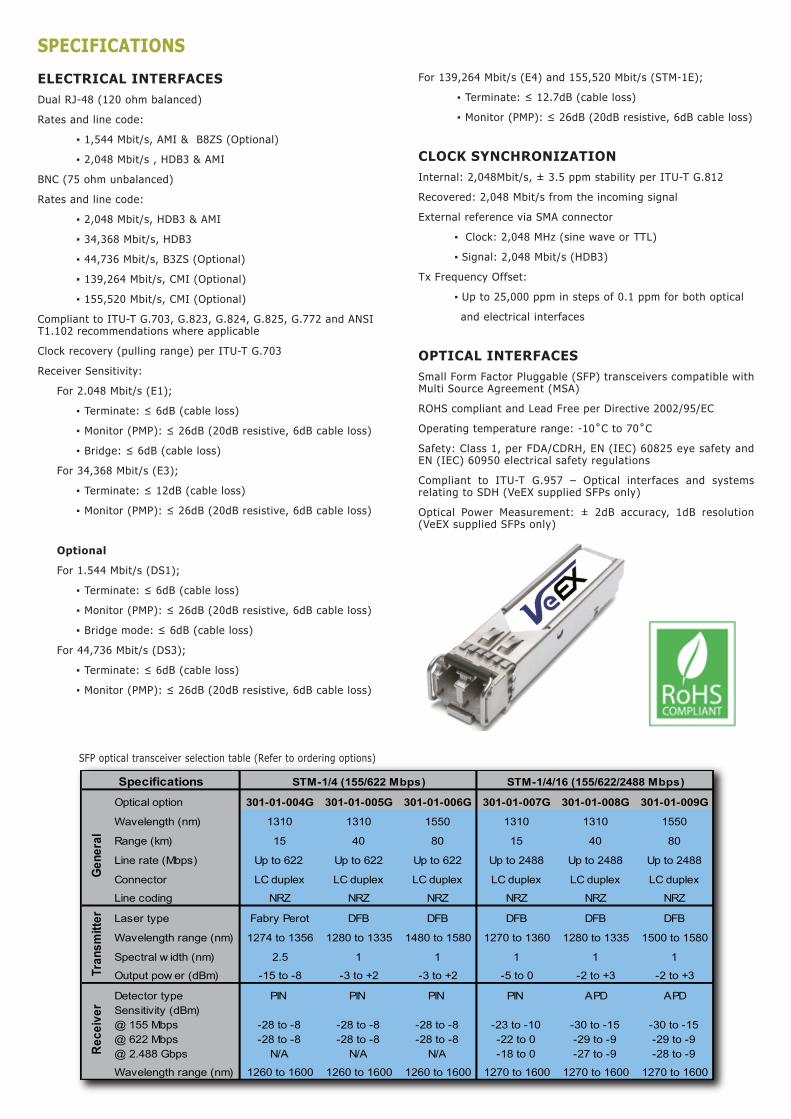
Transport Expert
SDH FUNCTIONS
OPERATING MODESTerminated modeMonitor modeIntrusive Through mode ▪ Modification of selected SOH bytes ▪ Alarm Generation and Error Insertion of selected defects and anomalies respectivelyNon-Intrusive Through mode ▪ Pass entire signal through without modification of section and line overhead bytes
SIGNAL STRUCTURESTM-1 (VC-n container equipped with); ▪ Framed or unframed PDH test pattern (per ITU-T 0.150)STM-4 (VC-n container equipped with); ▪ Framed or unframed PDH test pattern (per ITU-T 0.150) ▪ Bulk TSS (per ITU-T 0.181)STM-16 (VC-n container equipped with); ▪ Framed or unframed PDH test pattern (per ITU-T 0.150) ▪ Bulk TSS (per ITU-T 0.181)
MAPPINGS (According to ITU-T G.707)C-12 (unstructured or framed E1, asynchronous or byte synchronous)C-3 (unstructured or framed E3 or DS3) via AU-3 or AU-4C-4 (unstructured or framed E4)C-4-4c (STM-4 and STM-16)C-4-16c (STM-16)
OptionalC-11 (unstructured or framed DS1)
PATTERNSThe following test patterns can be generated:▪ PRBS: 211-1, 215-1, 220-1, 223-1, 231-1: normal or inverted▪ Fixed: 0000, 1111, 1010, 1000 and 1100▪ User programmable word: user defined up to 24 bits
ERRORSInsertion of; ▪ FAS, B1, B2, MS-REI, B3, HP-REI, LP-REI, LP-BIP, slips and bit errorsInsertion mode: ▪ Single and rate (1 x 10⁻³ to 5 x 10⁻⁶)Detection of; ▪ FAS, B1, B2, MS-REI, B3, HP-REI, LP-BIP, LP-REI, and bit errors
ALARMSGeneration of; ▪ LOS, LOF, MS-AIS, MS-RDI, RS-TIM, AU-LOP, AU-AIS, HP-UNEQ, HP-PLM, HP-RDI, HP-TIM, TU-LOM, TU-LOP, TU-AIS, LP-UNEQ, LP-PLM, LP-RDI, LP-RFI, LP-TIM, 2M AIS, 2M LOF, 2M RDIInsertion mode: Static (Enable/Disable)Monitoring and simultaneous detection of; ▪ LOS, LOF, OOF, RS-TIM, MS-AIS, MS-RDI, AU-AIS, AU-LOP, HP- UNEQ, HP-PLM, HP-TIM, HP-RDI, TU-LOM, TU-AIS, TU-LOP, LP- UNEQ, LP-PLM, LP-TIM, LP-RDI, LP-RFI
AUTOMATIC CONFIGURATIONConfigures tester to the incoming signal – Bit rate, framing, line coding and test pattern per ITU-T G.707, G.703, 0.151 and 0.181 recommendations where applicable
OVERHEAD ANALYSIS AND GENERATIONNetwork Architectures supported ▪ Linear (per G.783) or Ring (per G.841)
Analysis – Decode and display; SOH/POH bytes in hexadecimal, binary or ASCII formats; ▪ S1 synchronization status ▪ C2 HP signal label ▪ J0 trace identifier (16 bytes) in ASCII format ▪ J1 trace identifier (16 or 64 bytes) in ASCII format ▪ J2 trace identifier (16 or 64 bytes) in ASCII format ▪ K1, K2 APS Control ▪ V5 LP signal label
Generation - Programmable BytesRSOH: ▪ J0 trace: 1 byte hexadecimal or 16 byte ASCII sequence with CRC-7
MSOH: ▪ K1, K2 APS bytes per ITU-T G.783 and G.841 ▪ S1 synchronization status message
HO-POH (VC-4, VC-3): ▪ J1 trace: 16 byte ASCII with CRC-7 or 64 byte ASCII sequence ▪ C2 signal label ▪ H4 Sequence / Mutiframe Indicator ▪ G1 (bit 5) – End to end path status (RDI generation) ▪ K3 (bits 1-4) APS signaling
LO-POH (VC-3): ▪ J1 trace: 16 byte ASCII with CRC-7 or 64 byte ASCII sequence ▪ C2 signal label ▪ G1 (bit 5) – End to end path status (RDI generation) ▪ K3 (bits 1-4) APS signaling
LO-POH (VC-12, VC-11): ▪ V5 (bits 5-7) LP signal label ▪ J2 trace: 16 byte ASCII with CRC-7 or 64 byte ASCII sequence ▪ K4 (bits 3-4) LP APS signaling
OVERHEAD BERT:▪ Generation and analysis of PRBS pattern in DCC channels (D1-D3 or D4-D12 bytes) or E1, E2, F1, N1 and N2 bytes▪ PRBS: 223 -1, 220 -1, 215 -1, 211 -1 (inverted or non inverted)▪ Bit error counter, rate and errored seconds
POINTER ANALYSIS/GENERATIONAnalysis ▪ Current value, Increments, decrements, sum, difference ▪ New Data Flags (NDF) ▪ Tributary frequency offset (ppm of AU/TU)
Generation ▪ Single pointer, increment, decrement, or increment / decrement ▪ Programming of SS bits
TRIBUTARY SCANAutomatically scan VC-12s for errors, alarms and events using sequential BER
Transport Expert
PDH FUNCTIONS OPERATING MODESTerminated modeMonitor modeIntrusive Thru mode (E1 only)Bridge (E1 only, DS1 Optional)
SIGNAL STRUCTURE2,048 Mbit/s (E1) ▪ Unframed or Framed with/without CRC per ITU-T G.704 (PCM30, PCM30C, PCM31, PCM31C) ▪ Test signal in N/M x 64 kbit/s where N=1 to 30 34,368 Mbit/s (E3) ▪ Unframed or Framed according to ITU-T G.751
Optional 1,544 Mbit/s (DS1) ▪ Unframed or Framed SF (D4), ESF per ANSI and Telcordia standards where applicable ▪ Test signal in N x 64 kbit/s, N x 56 kbit/s where N=1 to 24 44,736 Mbit/s (DS3) ▪ Unframed or Framed M13 and C-Bit Parity per ITU-T G.752 or ITU-T G.704 139,264 Mbit/s (E4) ▪ Unframed or Framed according to ITU-T G.751
PATTERNSThe following test patterns can be generated:▪ PRBS: 211-1, 215-1, 220-1, 223-1, 231-1: normal or inverted▪ Fixed: 0000, 1111, 1010, 1000 and 1100▪ User programmable word: user defined up to 24 bits
ERRORSInsertion; ▪ 2,048 Mbit/s (E1): Code, FAS, CRC, EBIT, Bit errors ▪ 34,368 Mbit/s (E3): Code, FAS, 2M FAS, 2M, Bit errors ▪ Single or continuous rate (1 x 10⁻³ to 5 x 10⁻⁶)
Optional ▪ 1,544 Mbit/s (DS1): Code, FAS, Bit, Frame, CRC ▪ 44,736 Mbit/s (DS3): Code, FAS, MFAS, P/C-Parity, Bit errors ▪ 139,264 Mbit/s (E4): Code, FAS, Bit errors
Measurement: ▪ 2,048 Mbit/s (E1): Code, FAS, CRC, E-BIT and Bit errors ▪ 34,368 Mbit/s (E3): Code, FAS, Bit errors
Optional (DS1, DS3 and E4) – where applicable ▪ Code, FAS, MFAS, 2M CRC, P/C-Parity, Bit errors
ALARMSGeneration: ▪ 2,048 Mbit/s (E1): LOS, AIS, LOF, RDI ▪ 34,368 Mbit/s (E3): LOS, AIS, LOF, RDI, 2M LOF, 2M RDI ▪ Mode: Static (Enable/Disable)
Optional ▪ 1,544 Mbit/s (DS1): AIS, yellow, idle, LOS, LOF ▪ 44,736 Mbit/s (DS3): LOS, LOF, OOF, AIS, Parity ▪ 139,264 Mbit/s (E4): AIS, FAS RDI
Measurement: ▪ 2,048 Mbit/s (E1): LOS, AIS, LOF, LOMF, RDI and LSS ▪ 34,368 Mbit/s (E3): LOS, AIS, LOF, RDI and LSS
Optional (T-Carrier DS1/DS3) ▪ LOS, AIS, LOF, OOF, IDLE, YELLOW and LSS
MEASUREMENT FUNCTIONS
TEST RESULTSError count, ES, %ES, SES, %SES, UAS, %UAS, EFS, %EFS, AS, %AS, and rate for all events: errors, alarms and pointer events
PERFORMANCE ANALYSISMeasurements according to:▪ ITU-T G.821 recommendation: ES, EFS, SES, DM, and UAS with HRP 1% to 100%▪ ITU-T G.826 recommendation: EB, BBE, ES, EFS, SES, UAS. HRP of 1% to 100%. ▪ In service measurement (ISM) using B1, B2, B3, FAS, CRC or Code (E1). ▪ Out of service measurement (OOS) using bit errors (TSE)▪ ITU-T G.828 recommendation: ES, EFS, SES, BBE, SEP, UAS with HRP 1% to 100%▪ ITU-T G.829 recommendation: ES, EFS, SES, BBE, UAS on RSOH (B1), MSOH (B2) or TSE▪ ITU-T M.2100 recommendation: ES, EFS, SES, UAS with HRP 1% to 100%. ▪ User defined thresholds for Maintenance (MTCE) and Bringing into Service (BIS) objectives.▪ ITU-T M.2101 recommendation: ES, EFS, SES, BBE, SEP, UAS with HRP 1% to 100%. ▪ User defined thresholds for Maintenance (MTCE) and Bringing into Service (BIS) objectives. In service measurements on both near and far ends of path using TSE, HP-BIP (B3), MS-BIP (B2), RS-BIP (B1) and LP-BIP (V5)
COMMON FUNCTIONS AND MEASUREMENTS
AUTO CONFIGURATIONAvailable on all interfaces:Identification of received signal - instrument configuration based on network type, bit rate, line coding, framing, mapping, and test pattern
FREQUENCY MEASUREMENT▪ Optical & Electrical Interfaces: Hz & bit/s in ppm ▪ Resolution: 1Hz▪ TIE measurement on Pointer Justification Events
ROUND TRIP DELAYAvailable on all interfaces and mappings:▪ Measurement Range: 1μS to 10 seconds▪ Resolution: ±1μs or 1 U.I.
EVENT LOGGINGDate and time stamped events in tabular format
HISTOGRAMSAvailable for all interfaces▪ Display of Errors and Alarms versus time ▪ Resolution: Seconds, minutes, hours and days
LED INDICATORS▪ Fixed LEDs for Signal, Framing, Pattern and Errors/Alarms▪ Soft LEDs for SDH/PDH Alarms/Errors displaying historical events and conditions.
SPECIFICATIONS
ELECTRICAL INTERFACESDual RJ-48 (120 ohm balanced)
Rates and line code:
▪ 1,544 Mbit/s, AMI & B8ZS (Optional)
▪ 2,048 Mbit/s , HDB3 & AMI
BNC (75 ohm unbalanced)
Rates and line code:
▪ 2,048 Mbit/s, HDB3 & AMI
▪ 34,368 Mbit/s, HDB3
▪ 44,736 Mbit/s, B3ZS (Optional)
▪ 139,264 Mbit/s, CMI (Optional)
▪ 155,520 Mbit/s, CMI (Optional)
Compliant to ITU-T G.703, G.823, G.824, G.825, G.772 and ANSI T1.102 recommendations where applicable
Clock recovery (pulling range) per ITU-T G.703
Receiver Sensitivity:
For 2.048 Mbit/s (E1);
▪ Terminate: ≤ 6dB (cable loss)
▪ Monitor (PMP): ≤ 26dB (20dB resistive, 6dB cable loss)
▪ Bridge: ≤ 6dB (cable loss)
For 34,368 Mbit/s (E3);
▪ Terminate: ≤ 12dB (cable loss)
▪ Monitor (PMP): ≤ 26dB (20dB resistive, 6dB cable loss)
Optional
For 1.544 Mbit/s (DS1);
▪ Terminate: ≤ 6dB (cable loss)
▪ Monitor (PMP): ≤ 26dB (20dB resistive, 6dB cable loss)
▪ Bridge mode: ≤ 6dB (cable loss)
For 44,736 Mbit/s (DS3);
▪ Terminate: ≤ 6dB (cable loss)
▪ Monitor (PMP): ≤ 26dB (20dB resistive, 6dB cable loss)
For 139,264 Mbit/s (E4) and 155,520 Mbit/s (STM-1E);
▪ Terminate: ≤ 12.7dB (cable loss)
▪ Monitor (PMP): ≤ 26dB (20dB resistive, 6dB cable loss)
CLOCK SYNCHRONIZATIONInternal: 2,048Mbit/s, ± 3.5 ppm stability per ITU-T G.812
Recovered: 2,048 Mbit/s from the incoming signal
External reference via SMA connector
▪ Clock: 2,048 MHz (sine wave or TTL)
▪ Signal: 2,048 Mbit/s (HDB3)
Tx Frequency Offset:
▪ Up to 25,000 ppm in steps of 0.1 ppm for both optical
and electrical interfaces
OPTICAL INTERFACESSmall Form Factor Pluggable (SFP) transceivers compatible with Multi Source Agreement (MSA)
ROHS compliant and Lead Free per Directive 2002/95/EC
Operating temperature range: -10˚C to 70˚C
Safety: Class 1, per FDA/CDRH, EN (IEC) 60825 eye safety and EN (IEC) 60950 electrical safety regulations
Compliant to ITU-T G.957 – Optical interfaces and systems relating to SDH (VeEX supplied SFPs only)
Optical Power Measurement: ± 2dB accuracy, 1dB resolution (VeEX supplied SFPs only)
SFP optical transceiver selection table (Refer to ordering options)
Optical option 301-01-004G 301-01-005G 301-01-006G 301-01-007G 301-01-008G 301-01-009G
Wavelength (nm) 1310 1310 1550 1310 1310 1550
Range (km) 15 40 80 15 40 80
Line rate (Mbps) Up to 622 Up to 622 Up to 622 Up to 2488 Up to 2488 Up to 2488
Connector LC duplex LC duplex LC duplex LC duplex LC duplex LC duplex
Line coding NRZ NRZ NRZ NRZ NRZ NRZ
Laser type Fabry Perot DFB DFB DFB DFB DFB
Wavelength range (nm) 1274 to 1356 1280 to 1335 1480 to 1580 1270 to 1360 1280 to 1335 1500 to 1580
Spectral w idth (nm) 2.5 1 1 1 1 1
Output pow er (dBm) -15 to -8 -3 to +2 -3 to +2 -5 to 0 -2 to +3 -2 to +3
Detector type PIN PIN PIN PIN APD APDSensitivity (dBm)@ 155 Mbps@ 622 Mbps@ 2.488 Gbps
-28 to -8-28 to -8
N/A
-28 to -8-28 to -8
N/A
-28 to -8-28 to -8
N/A
-23 to -10-22 to 0-18 to 0
-30 to -15-29 to -9-27 to -9
-30 to -15-29 to -9-28 to -9
Wavelength range (nm) 1260 to 1600 1260 to 1600 1260 to 1600 1270 to 1600 1270 to 1600 1270 to 1600
STM-1/4/16 (155/622/2488 Mbps)Specifications
Tran
smitt
erRe
ceiv
erGe
nera
l
STM-1/4 (155/622 Mbps)
ORDERING INFORMATION
Z04-00-001P VePAL TX150E Handheld SDH/PDH Test Set
Interfaces/Test Options499-05-040 1.544Mbit/s (DS1) and C-11 Mapping499-05-041 45Mbit/s Testing499-05-042 155Mbit/s Electrical Testing499-05-043 155 Mbit/s Optical Testing (require SFP option)499-05-044 155/622 Mbit/s Optical Testing (require SFP option)499-05-045 155/622/2488 Mbit/s Optical Testing (require SFP option)499-05-046 APS/Service Disruption Measurement499-05-047 Tandem Connection Monitoring499-05-048 ITU-T G.783 Pointer Test Sequences499-05-049 2 Mbit/s and 34 Mbit/s Pulse Mask Analysis499-05-050 1.5 Mbit/s Pulse Mask Analysis499-05-051 45 Mbit/s Pulse Mask Analysis499-05-052 139 Mbit/s Testing
SFP Transceiver Options301-01-004G 1310nm IR (15km), 155M/622M STM1/4 - OC3/12301-01-005G 1310nm LR (40km), 155M/622M STM1/4 - OC3/12301-01-006G 1550nm LR (80km), 155M/622M STM1/4 - OC3/12301-01-007G 1310nm IR (15km), 155M/622M/2.5G STM1/4/16 - OC3/12/48301-01-008G 1310nm LR (40km), 155M/622M/2.5G STM1/4/16 - OC3/12/48301-01-009G 1550nm LR (80km), 155M/622M/2.5G STM1/4/16 - OC3/12/48
Additional Options499-05-001 Web Browser (require advanced IP option)499-05-002 NetWiz499-05-003 Remote Control499-05-007 VoIP Expert499-05-008 IPTV ExpertZ88-00-001G WiFi Wiz, incl. USB WiFi AdaptorZ88-00-001P VoIP Call Expert, incl. VoIP USB Adaptor & EarplugZ88-00-005G Advanced IP, incl. Ethernet Cable
Recommended AccessoriesF02-00-008G RJ48 to BNC Test Cable, 2 mF02-00-009G RJ48 to 3-Pin Banana Test Cable, 2 mF02-00-010G BNC to BNC Test Cable, 2 mF05-00-005G LCPC to LCPC Duplex Optical Patchcord, 2 mF05-00-006G LCPC to SCPC Duplex Optical Patchcord, 2 mF05-00-007G LCPC to FCPC Duplex Optical Patchcord, 2 m
Replacement Items405-02-001G Screen ProtectorA01-00-001G AC AdaptorA02-00-001G Car AdaptorB02-03-001G Battery PackC01-00-001G Carrying Case (Basic)C02-00-002G Carrying PouchC03-00-001G Shoulder StrapF02-00-001G Ethernet Cable RJ45 to RJ45 2 m (6 ft)F04-00-001G Power Cord - US 2 m (6 ft)F04-00-002G Power Cord - EU 2 m (6 ft)F04-00-003G Power Cord - UK 2 m (6 ft)Z77-00-001G Stylus (pack of 5)
SDH/PDH MEASUREMENT OPTIONSPULSE MASK ANALYSISPDH ▪ Bit rates: 2,048 Mbit/s (E1) and 34,368 Mbit/s (E3) ▪ Mode: Non-Intrusive ▪ Display: Pulse shape with Conformance mask verification ▪ Parameters: Width, Rise/Fall time, Overshoot/Undershoot ▪ Conformance Mask: G.703
T-Carrier ▪ Bit rates: 1,544 Mbit/s (DS1) and 44,736 Mbit/s (DS3) ▪ Conformance Masks: G.703, ANSI T1.102, T1.403, T1.404 where applicable
AUTOMATIC PROTECTION SWITCHING (APS) / SERVICE DISRUPTION MEASUREMENT ▪ Measurement of disruption time on SDH & PDH interfaces ▪ Tributaries: PDH (E1), SDH ▪ Pass/Fail Range: 1 ms to 10 seconds ▪ Resolution: 1 ms ▪ Triggers: MS-AIS, AU-AIS, TU-AIS, B2 ▪ APS Byte (K1/K2) capture and decode ▪ Service Disruption sensor events - LOS, LOF, AIS, TSE ▪ Service Disruption measurements: ▪ Longest, shortest, total and average disruption time ▪ Disruption count
POINTER ANALYSIS/GENERATIONGeneration ▪ ITU-T G.783 pointer sequences
TANDEM CONNECTION MONITORING (TCM)Generation and analysis of N1 and N2 bytesErrors generated: ▪ TC-IEC, TC-BIP, TC-REI, OEIAlarms generated: ▪ TC-RDI, TC-UNEQ, TC-LTC, TC-AIS, TC-ODI Detection, display, analysis and storage of events: ▪ TC-IEC, TC-AIS, TC-REI, TC-RDI, TC-OEI, TC-LTC, TC-UNEQ, TC-ODI, TC-TIM ▪ Analysis and generation of APId (Access Point Identifier)
General SpecificationsSize 210 x 100 x 55 mm (H x W x D) (8.25 x 3.75 x 2.25 in)Weight Less than 1 kg (less than 2.2 lbs)Battery LiIon Battery Pack, Operating time > 3 hoursAC Adapter Input: 100-240 VAC, 50-60 Hz Output: 15VDC, 3.5AOperating Temperature -10˚C to 50˚C (14˚F to 122˚F)Storage Temperature -20˚C to 70˚C (-4˚F to 158˚F)Humidity 5% to 95% non-condensingDisplay 3.5”QVGA 320x240 full color touch screenRuggedness Survives 1m (3 ft) drop to concrete on all sidesWater-resistance May be used in heavy rainInterfaces USB 2.0 Host and Client, RJ45 10/100T EthernetLanguages Multiple languages can be supported
VeEX Inc.2255, Martin Ave., Suite G,Santa Clara, CA 95050, USATel: +1.408.970.9090Fax: [email protected]
© 2007-2008 VeEX Inc. All rights reserved.VeEX is a registered trademark of VeEX Inc. The information contained in this document is accurate. However, we reserve the right to change any contents at any time without notice. We accept no responsibility for any errors or omissions. In case of discrepancy, the web version takes precedence over any printed literature.D05-00-016P B00 2008/05
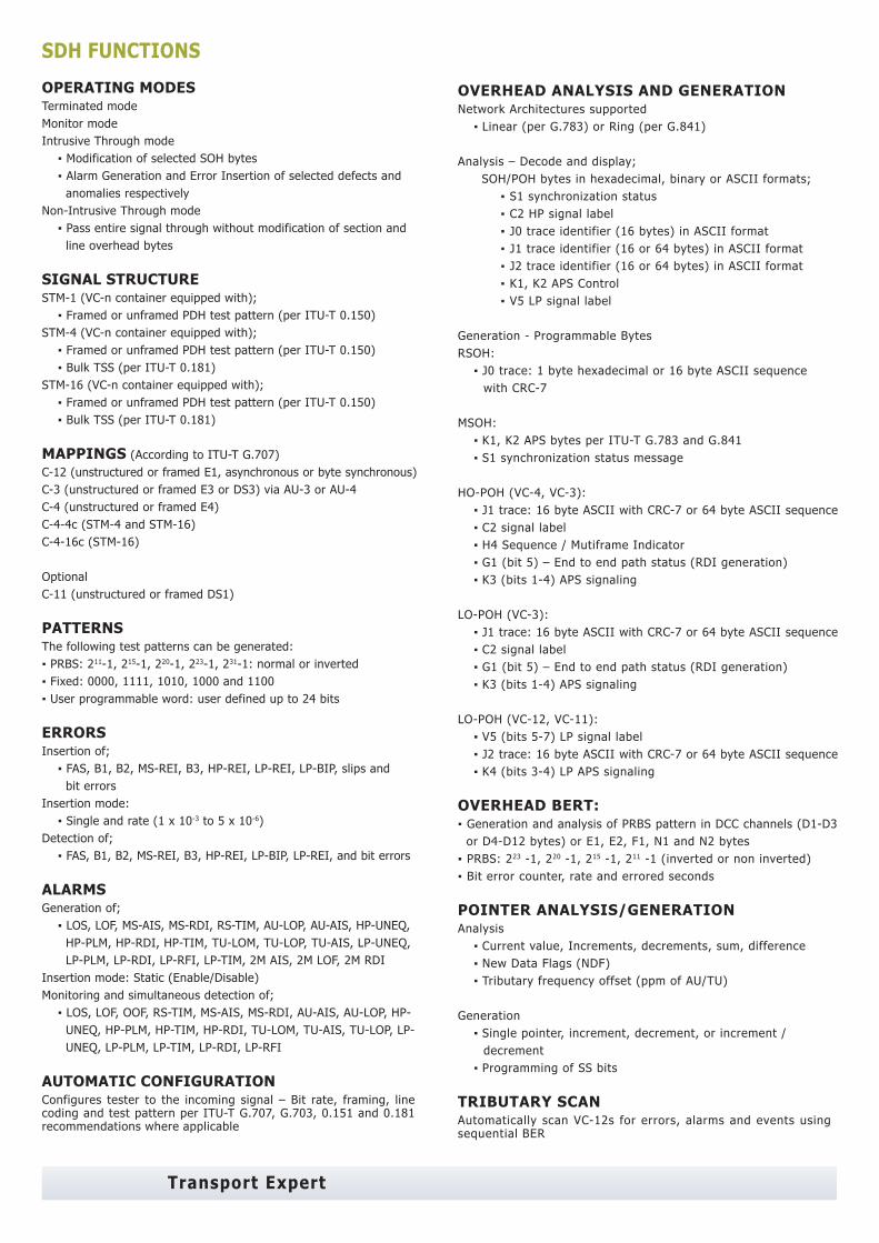
Transport Expert
SDH FUNCTIONS
OPERATING MODESTerminated modeMonitor modeIntrusive Through mode ▪ Modification of selected SOH bytes ▪ Alarm Generation and Error Insertion of selected defects and anomalies respectivelyNon-Intrusive Through mode ▪ Pass entire signal through without modification of section and line overhead bytes
SIGNAL STRUCTURESTM-1 (VC-n container equipped with); ▪ Framed or unframed PDH test pattern (per ITU-T 0.150)STM-4 (VC-n container equipped with); ▪ Framed or unframed PDH test pattern (per ITU-T 0.150) ▪ Bulk TSS (per ITU-T 0.181)STM-16 (VC-n container equipped with); ▪ Framed or unframed PDH test pattern (per ITU-T 0.150) ▪ Bulk TSS (per ITU-T 0.181)
MAPPINGS (According to ITU-T G.707)C-12 (unstructured or framed E1, asynchronous or byte synchronous)C-3 (unstructured or framed E3 or DS3) via AU-3 or AU-4C-4 (unstructured or framed E4)C-4-4c (STM-4 and STM-16)C-4-16c (STM-16)
OptionalC-11 (unstructured or framed DS1)
PATTERNSThe following test patterns can be generated:▪ PRBS: 211-1, 215-1, 220-1, 223-1, 231-1: normal or inverted▪ Fixed: 0000, 1111, 1010, 1000 and 1100▪ User programmable word: user defined up to 24 bits
ERRORSInsertion of; ▪ FAS, B1, B2, MS-REI, B3, HP-REI, LP-REI, LP-BIP, slips and bit errorsInsertion mode: ▪ Single and rate (1 x 10⁻³ to 5 x 10⁻⁶)Detection of; ▪ FAS, B1, B2, MS-REI, B3, HP-REI, LP-BIP, LP-REI, and bit errors
ALARMSGeneration of; ▪ LOS, LOF, MS-AIS, MS-RDI, RS-TIM, AU-LOP, AU-AIS, HP-UNEQ, HP-PLM, HP-RDI, HP-TIM, TU-LOM, TU-LOP, TU-AIS, LP-UNEQ, LP-PLM, LP-RDI, LP-RFI, LP-TIM, 2M AIS, 2M LOF, 2M RDIInsertion mode: Static (Enable/Disable)Monitoring and simultaneous detection of; ▪ LOS, LOF, OOF, RS-TIM, MS-AIS, MS-RDI, AU-AIS, AU-LOP, HP- UNEQ, HP-PLM, HP-TIM, HP-RDI, TU-LOM, TU-AIS, TU-LOP, LP- UNEQ, LP-PLM, LP-TIM, LP-RDI, LP-RFI
AUTOMATIC CONFIGURATIONConfigures tester to the incoming signal – Bit rate, framing, line coding and test pattern per ITU-T G.707, G.703, 0.151 and 0.181 recommendations where applicable
OVERHEAD ANALYSIS AND GENERATIONNetwork Architectures supported ▪ Linear (per G.783) or Ring (per G.841)
Analysis – Decode and display; SOH/POH bytes in hexadecimal, binary or ASCII formats; ▪ S1 synchronization status ▪ C2 HP signal label ▪ J0 trace identifier (16 bytes) in ASCII format ▪ J1 trace identifier (16 or 64 bytes) in ASCII format ▪ J2 trace identifier (16 or 64 bytes) in ASCII format ▪ K1, K2 APS Control ▪ V5 LP signal label
Generation - Programmable BytesRSOH: ▪ J0 trace: 1 byte hexadecimal or 16 byte ASCII sequence with CRC-7
MSOH: ▪ K1, K2 APS bytes per ITU-T G.783 and G.841 ▪ S1 synchronization status message
HO-POH (VC-4, VC-3): ▪ J1 trace: 16 byte ASCII with CRC-7 or 64 byte ASCII sequence ▪ C2 signal label ▪ H4 Sequence / Mutiframe Indicator ▪ G1 (bit 5) – End to end path status (RDI generation) ▪ K3 (bits 1-4) APS signaling
LO-POH (VC-3): ▪ J1 trace: 16 byte ASCII with CRC-7 or 64 byte ASCII sequence ▪ C2 signal label ▪ G1 (bit 5) – End to end path status (RDI generation) ▪ K3 (bits 1-4) APS signaling
LO-POH (VC-12, VC-11): ▪ V5 (bits 5-7) LP signal label ▪ J2 trace: 16 byte ASCII with CRC-7 or 64 byte ASCII sequence ▪ K4 (bits 3-4) LP APS signaling
OVERHEAD BERT:▪ Generation and analysis of PRBS pattern in DCC channels (D1-D3 or D4-D12 bytes) or E1, E2, F1, N1 and N2 bytes▪ PRBS: 223 -1, 220 -1, 215 -1, 211 -1 (inverted or non inverted)▪ Bit error counter, rate and errored seconds
POINTER ANALYSIS/GENERATIONAnalysis ▪ Current value, Increments, decrements, sum, difference ▪ New Data Flags (NDF) ▪ Tributary frequency offset (ppm of AU/TU)
Generation ▪ Single pointer, increment, decrement, or increment / decrement ▪ Programming of SS bits
TRIBUTARY SCANAutomatically scan VC-12s for errors, alarms and events using sequential BER
Transport Expert
PDH FUNCTIONS OPERATING MODESTerminated modeMonitor modeIntrusive Thru mode (E1 only)Bridge (E1 only, DS1 Optional)
SIGNAL STRUCTURE2,048 Mbit/s (E1) ▪ Unframed or Framed with/without CRC per ITU-T G.704 (PCM30, PCM30C, PCM31, PCM31C) ▪ Test signal in N/M x 64 kbit/s where N=1 to 30 34,368 Mbit/s (E3) ▪ Unframed or Framed according to ITU-T G.751
Optional 1,544 Mbit/s (DS1) ▪ Unframed or Framed SF (D4), ESF per ANSI and Telcordia standards where applicable ▪ Test signal in N x 64 kbit/s, N x 56 kbit/s where N=1 to 24 44,736 Mbit/s (DS3) ▪ Unframed or Framed M13 and C-Bit Parity per ITU-T G.752 or ITU-T G.704 139,264 Mbit/s (E4) ▪ Unframed or Framed according to ITU-T G.751
PATTERNSThe following test patterns can be generated:▪ PRBS: 211-1, 215-1, 220-1, 223-1, 231-1: normal or inverted▪ Fixed: 0000, 1111, 1010, 1000 and 1100▪ User programmable word: user defined up to 24 bits
ERRORSInsertion; ▪ 2,048 Mbit/s (E1): Code, FAS, CRC, EBIT, Bit errors ▪ 34,368 Mbit/s (E3): Code, FAS, 2M FAS, 2M, Bit errors ▪ Single or continuous rate (1 x 10⁻³ to 5 x 10⁻⁶)
Optional ▪ 1,544 Mbit/s (DS1): Code, FAS, Bit, Frame, CRC ▪ 44,736 Mbit/s (DS3): Code, FAS, MFAS, P/C-Parity, Bit errors ▪ 139,264 Mbit/s (E4): Code, FAS, Bit errors
Measurement: ▪ 2,048 Mbit/s (E1): Code, FAS, CRC, E-BIT and Bit errors ▪ 34,368 Mbit/s (E3): Code, FAS, Bit errors
Optional (DS1, DS3 and E4) – where applicable ▪ Code, FAS, MFAS, 2M CRC, P/C-Parity, Bit errors
ALARMSGeneration: ▪ 2,048 Mbit/s (E1): LOS, AIS, LOF, RDI ▪ 34,368 Mbit/s (E3): LOS, AIS, LOF, RDI, 2M LOF, 2M RDI ▪ Mode: Static (Enable/Disable)
Optional ▪ 1,544 Mbit/s (DS1): AIS, yellow, idle, LOS, LOF ▪ 44,736 Mbit/s (DS3): LOS, LOF, OOF, AIS, Parity ▪ 139,264 Mbit/s (E4): AIS, FAS RDI
Measurement: ▪ 2,048 Mbit/s (E1): LOS, AIS, LOF, LOMF, RDI and LSS ▪ 34,368 Mbit/s (E3): LOS, AIS, LOF, RDI and LSS
Optional (T-Carrier DS1/DS3) ▪ LOS, AIS, LOF, OOF, IDLE, YELLOW and LSS
MEASUREMENT FUNCTIONS
TEST RESULTSError count, ES, %ES, SES, %SES, UAS, %UAS, EFS, %EFS, AS, %AS, and rate for all events: errors, alarms and pointer events
PERFORMANCE ANALYSISMeasurements according to:▪ ITU-T G.821 recommendation: ES, EFS, SES, DM, and UAS with HRP 1% to 100%▪ ITU-T G.826 recommendation: EB, BBE, ES, EFS, SES, UAS. HRP of 1% to 100%. ▪ In service measurement (ISM) using B1, B2, B3, FAS, CRC or Code (E1). ▪ Out of service measurement (OOS) using bit errors (TSE)▪ ITU-T G.828 recommendation: ES, EFS, SES, BBE, SEP, UAS with HRP 1% to 100%▪ ITU-T G.829 recommendation: ES, EFS, SES, BBE, UAS on RSOH (B1), MSOH (B2) or TSE▪ ITU-T M.2100 recommendation: ES, EFS, SES, UAS with HRP 1% to 100%. ▪ User defined thresholds for Maintenance (MTCE) and Bringing into Service (BIS) objectives.▪ ITU-T M.2101 recommendation: ES, EFS, SES, BBE, SEP, UAS with HRP 1% to 100%. ▪ User defined thresholds for Maintenance (MTCE) and Bringing into Service (BIS) objectives. In service measurements on both near and far ends of path using TSE, HP-BIP (B3), MS-BIP (B2), RS-BIP (B1) and LP-BIP (V5)
COMMON FUNCTIONS AND MEASUREMENTS
AUTO CONFIGURATIONAvailable on all interfaces:Identification of received signal - instrument configuration based on network type, bit rate, line coding, framing, mapping, and test pattern
FREQUENCY MEASUREMENT▪ Optical & Electrical Interfaces: Hz & bit/s in ppm ▪ Resolution: 1Hz▪ TIE measurement on Pointer Justification Events
ROUND TRIP DELAYAvailable on all interfaces and mappings:▪ Measurement Range: 1μS to 10 seconds▪ Resolution: ±1μs or 1 U.I.
EVENT LOGGINGDate and time stamped events in tabular format
HISTOGRAMSAvailable for all interfaces▪ Display of Errors and Alarms versus time ▪ Resolution: Seconds, minutes, hours and days
LED INDICATORS▪ Fixed LEDs for Signal, Framing, Pattern and Errors/Alarms▪ Soft LEDs for SDH/PDH Alarms/Errors displaying historical events and conditions.
ORDERING INFORMATION
Z04-00-001P VePAL TX150E Handheld SDH/PDH Test Set
Interfaces/Test Options499-05-040 1.544Mbit/s (DS1) and C-11 Mapping499-05-041 45Mbit/s Testing499-05-042 155Mbit/s Electrical Testing499-05-043 155 Mbit/s Optical Testing (require SFP option)499-05-044 155/622 Mbit/s Optical Testing (require SFP option)499-05-045 155/622/2488 Mbit/s Optical Testing (require SFP option)499-05-046 APS/Service Disruption Measurement499-05-047 Tandem Connection Monitoring499-05-048 ITU-T G.783 Pointer Test Sequences499-05-049 2 Mbit/s and 34 Mbit/s Pulse Mask Analysis499-05-050 1.5 Mbit/s Pulse Mask Analysis499-05-051 45 Mbit/s Pulse Mask Analysis499-05-052 139 Mbit/s Testing
SFP Transceiver Options301-01-004G 1310nm IR (15km), 155M/622M STM1/4 - OC3/12301-01-005G 1310nm LR (40km), 155M/622M STM1/4 - OC3/12301-01-006G 1550nm LR (80km), 155M/622M STM1/4 - OC3/12301-01-007G 1310nm IR (15km), 155M/622M/2.5G STM1/4/16 - OC3/12/48301-01-008G 1310nm LR (40km), 155M/622M/2.5G STM1/4/16 - OC3/12/48301-01-009G 1550nm LR (80km), 155M/622M/2.5G STM1/4/16 - OC3/12/48
Additional Options499-05-001 Web Browser (require advanced IP option)499-05-002 NetWiz499-05-003 Remote Control499-05-007 VoIP Expert499-05-008 IPTV ExpertZ88-00-001G WiFi Wiz, incl. USB WiFi AdaptorZ88-00-001P VoIP Call Expert, incl. VoIP USB Adaptor & EarplugZ88-00-005G Advanced IP, incl. Ethernet Cable
Recommended AccessoriesF02-00-008G RJ48 to BNC Test Cable, 2 mF02-00-009G RJ48 to 3-Pin Banana Test Cable, 2 mF02-00-010G BNC to BNC Test Cable, 2 mF05-00-005G LCPC to LCPC Duplex Optical Patchcord, 2 mF05-00-006G LCPC to SCPC Duplex Optical Patchcord, 2 mF05-00-007G LCPC to FCPC Duplex Optical Patchcord, 2 m
Replacement Items405-02-001G Screen ProtectorA01-00-001G AC AdaptorA02-00-001G Car AdaptorB02-03-001G Battery PackC01-00-001G Carrying Case (Basic)C02-00-002G Carrying PouchC03-00-001G Shoulder StrapF02-00-001G Ethernet Cable RJ45 to RJ45 2 m (6 ft)F04-00-001G Power Cord - US 2 m (6 ft)F04-00-002G Power Cord - EU 2 m (6 ft)F04-00-003G Power Cord - UK 2 m (6 ft)Z77-00-001G Stylus (pack of 5)
SDH/PDH MEASUREMENT OPTIONSPULSE MASK ANALYSISPDH ▪ Bit rates: 2,048 Mbit/s (E1) and 34,368 Mbit/s (E3) ▪ Mode: Non-Intrusive ▪ Display: Pulse shape with Conformance mask verification ▪ Parameters: Width, Rise/Fall time, Overshoot/Undershoot ▪ Conformance Mask: G.703
T-Carrier ▪ Bit rates: 1,544 Mbit/s (DS1) and 44,736 Mbit/s (DS3) ▪ Conformance Masks: G.703, ANSI T1.102, T1.403, T1.404 where applicable
AUTOMATIC PROTECTION SWITCHING (APS) / SERVICE DISRUPTION MEASUREMENT ▪ Measurement of disruption time on SDH & PDH interfaces ▪ Tributaries: PDH (E1), SDH ▪ Pass/Fail Range: 1 ms to 10 seconds ▪ Resolution: 1 ms ▪ Triggers: MS-AIS, AU-AIS, TU-AIS, B2 ▪ APS Byte (K1/K2) capture and decode ▪ Service Disruption sensor events - LOS, LOF, AIS, TSE ▪ Service Disruption measurements: ▪ Longest, shortest, total and average disruption time ▪ Disruption count
POINTER ANALYSIS/GENERATIONGeneration ▪ ITU-T G.783 pointer sequences
TANDEM CONNECTION MONITORING (TCM)Generation and analysis of N1 and N2 bytesErrors generated: ▪ TC-IEC, TC-BIP, TC-REI, OEIAlarms generated: ▪ TC-RDI, TC-UNEQ, TC-LTC, TC-AIS, TC-ODI Detection, display, analysis and storage of events: ▪ TC-IEC, TC-AIS, TC-REI, TC-RDI, TC-OEI, TC-LTC, TC-UNEQ, TC-ODI, TC-TIM ▪ Analysis and generation of APId (Access Point Identifier)
General SpecificationsSize 210 x 100 x 55 mm (H x W x D) (8.25 x 3.75 x 2.25 in)Weight Less than 1 kg (less than 2.2 lbs)Battery LiIon Battery Pack, Operating time > 3 hoursAC Adapter Input: 100-240 VAC, 50-60 Hz Output: 15VDC, 3.5AOperating Temperature -10˚C to 50˚C (14˚F to 122˚F)Storage Temperature -20˚C to 70˚C (-4˚F to 158˚F)Humidity 5% to 95% non-condensingDisplay 3.5”QVGA 320x240 full color touch screenRuggedness Survives 1m (3 ft) drop to concrete on all sidesWater-resistance May be used in heavy rainInterfaces USB 2.0 Host and Client, RJ45 10/100T EthernetLanguages Multiple languages can be supported
VeEX Inc.2255, Martin Ave., Suite G,Santa Clara, CA 95050, USATel: +1.408.970.9090Fax: [email protected]
© 2007-2008 VeEX Inc. All rights reserved.VeEX is a registered trademark of VeEX Inc. The information contained in this document is accurate. However, we reserve the right to change any contents at any time without notice. We accept no responsibility for any errors or omissions. In case of discrepancy, the web version takes precedence over any printed literature.D05-00-016P B00 2008/05
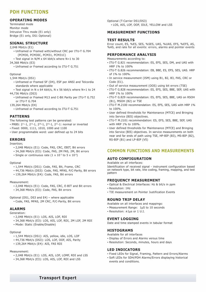
Transport Expert
PDH FUNCTIONS OPERATING MODESTerminated modeMonitor modeIntrusive Thru mode (E1 only)Bridge (E1 only, DS1 Optional)
SIGNAL STRUCTURE2,048 Mbit/s (E1) ▪ Unframed or Framed with/without CRC per ITU-T G.704 (PCM30, PCM30C, PCM31, PCM31C) ▪ Test signal in N/M x 64 kbit/s where N=1 to 30 34,368 Mbit/s (E3) ▪ Unframed or Framed according to ITU-T G.751
Optional 1,544 Mbit/s (DS1) ▪ Unframed or Framed SF (D4), ESF per ANSI and Telcordia standards where applicable ▪ Test signal in N x 64 kbit/s, N x 56 kbit/s where N=1 to 24 44,736 Mbit/s (DS3) ▪ Unframed or Framed M13 and C-Bit Parity per ITU-T G.752 or ITU-T G.704 139,264 Mbit/s (E4) ▪ Unframed or Framed according to ITU-T G.751
PATTERNSThe following test patterns can be generated:▪ PRBS: 211-1, 215-1, 220-1, 223-1, 231-1: normal or inverted▪ Fixed: 0000, 1111, 1010, 1000 and 1100▪ User programmable word: user defined up to 24 bits
ERRORSInsertion; ▪ 2,048 Mbit/s (E1): Code, FAS, CRC, EBIT, Bit errors ▪ 34,368 Mbit/s (E3): Code, FAS, 2M FAS, 2M, Bit errors ▪ Single or continuous rate (1 x 10⁻³ to 5 x 10⁻⁶)
Optional ▪ 1,544 Mbit/s (DS1): Code, FAS, Bit, Frame, CRC ▪ 44,736 Mbit/s (DS3): Code, FAS, MFAS, P/C-Parity, Bit errors ▪ 139,264 Mbit/s (E4): Code, FAS, Bit errors
Measurement: ▪ 2,048 Mbit/s (E1): Code, FAS, CRC, E-BIT and Bit errors ▪ 34,368 Mbit/s (E3): Code, FAS, Bit errors
Optional (DS1, DS3 and E4) – where applicable ▪ Code, FAS, MFAS, 2M CRC, P/C-Parity, Bit errors
ALARMSGeneration: ▪ 2,048 Mbit/s (E1): LOS, AIS, LOF, RDI ▪ 34,368 Mbit/s (E3): LOS, AIS, LOF, RDI, 2M LOF, 2M RDI ▪ Mode: Static (Enable/Disable)
Optional ▪ 1,544 Mbit/s (DS1): AIS, yellow, idle, LOS, LOF ▪ 44,736 Mbit/s (DS3): LOS, LOF, OOF, AIS, Parity ▪ 139,264 Mbit/s (E4): AIS, FAS RDI
Measurement: ▪ 2,048 Mbit/s (E1): LOS, AIS, LOF, LOMF, RDI and LSS ▪ 34,368 Mbit/s (E3): LOS, AIS, LOF, RDI and LSS
Optional (T-Carrier DS1/DS3) ▪ LOS, AIS, LOF, OOF, IDLE, YELLOW and LSS
MEASUREMENT FUNCTIONS
TEST RESULTSError count, ES, %ES, SES, %SES, UAS, %UAS, EFS, %EFS, AS, %AS, and rate for all events: errors, alarms and pointer events
PERFORMANCE ANALYSISMeasurements according to:▪ ITU-T G.821 recommendation: ES, EFS, SES, DM, and UAS with HRP 1% to 100%▪ ITU-T G.826 recommendation: EB, BBE, ES, EFS, SES, UAS. HRP of 1% to 100%. ▪ In service measurement (ISM) using B1, B2, B3, FAS, CRC or Code (E1). ▪ Out of service measurement (OOS) using bit errors (TSE)▪ ITU-T G.828 recommendation: ES, EFS, SES, BBE, SEP, UAS with HRP 1% to 100%▪ ITU-T G.829 recommendation: ES, EFS, SES, BBE, UAS on RSOH (B1), MSOH (B2) or TSE▪ ITU-T M.2100 recommendation: ES, EFS, SES, UAS with HRP 1% to 100%. ▪ User defined thresholds for Maintenance (MTCE) and Bringing into Service (BIS) objectives.▪ ITU-T M.2101 recommendation: ES, EFS, SES, BBE, SEP, UAS with HRP 1% to 100%. ▪ User defined thresholds for Maintenance (MTCE) and Bringing into Service (BIS) objectives. In service measurements on both near and far ends of path using TSE, HP-BIP (B3), MS-BIP (B2), RS-BIP (B1) and LP-BIP (V5)
COMMON FUNCTIONS AND MEASUREMENTS
AUTO CONFIGURATIONAvailable on all interfaces:Identification of received signal - instrument configuration based on network type, bit rate, line coding, framing, mapping, and test pattern
FREQUENCY MEASUREMENT▪ Optical & Electrical Interfaces: Hz & bit/s in ppm ▪ Resolution: 1Hz▪ TIE measurement on Pointer Justification Events
ROUND TRIP DELAYAvailable on all interfaces and mappings:▪ Measurement Range: 1μS to 10 seconds▪ Resolution: ±1μs or 1 U.I.
EVENT LOGGINGDate and time stamped events in tabular format
HISTOGRAMSAvailable for all interfaces▪ Display of Errors and Alarms versus time ▪ Resolution: Seconds, minutes, hours and days
LED INDICATORS▪ Fixed LEDs for Signal, Framing, Pattern and Errors/Alarms▪ Soft LEDs for SDH/PDH Alarms/Errors displaying historical events and conditions.
ORDERING INFORMATION
Z04-00-001P VePAL TX150E Handheld SDH/PDH Test Set
Interfaces/Test Options499-05-040 1.544Mbit/s (DS1) and C-11 Mapping499-05-041 45Mbit/s Testing499-05-042 155Mbit/s Electrical Testing499-05-043 155 Mbit/s Optical Testing (require SFP option)499-05-044 155/622 Mbit/s Optical Testing (require SFP option)499-05-045 155/622/2488 Mbit/s Optical Testing (require SFP option)499-05-046 APS/Service Disruption Measurement499-05-047 Tandem Connection Monitoring499-05-048 ITU-T G.783 Pointer Test Sequences499-05-049 2 Mbit/s and 34 Mbit/s Pulse Mask Analysis499-05-050 1.5 Mbit/s Pulse Mask Analysis499-05-051 45 Mbit/s Pulse Mask Analysis499-05-052 139 Mbit/s Testing
SFP Transceiver Options301-01-004G 1310nm IR (15km), 155M/622M STM1/4 - OC3/12301-01-005G 1310nm LR (40km), 155M/622M STM1/4 - OC3/12301-01-006G 1550nm LR (80km), 155M/622M STM1/4 - OC3/12301-01-007G 1310nm IR (15km), 155M/622M/2.5G STM1/4/16 - OC3/12/48301-01-008G 1310nm LR (40km), 155M/622M/2.5G STM1/4/16 - OC3/12/48301-01-009G 1550nm LR (80km), 155M/622M/2.5G STM1/4/16 - OC3/12/48
Additional Options499-05-001 Web Browser (require advanced IP option)499-05-002 NetWiz499-05-003 Remote Control499-05-007 VoIP Expert499-05-008 IPTV ExpertZ88-00-001G WiFi Wiz, incl. USB WiFi AdaptorZ88-00-001P VoIP Call Expert, incl. VoIP USB Adaptor & EarplugZ88-00-005G Advanced IP, incl. Ethernet Cable
Recommended AccessoriesF02-00-008G RJ48 to BNC Test Cable, 2 mF02-00-009G RJ48 to 3-Pin Banana Test Cable, 2 mF02-00-010G BNC to BNC Test Cable, 2 mF05-00-005G LCPC to LCPC Duplex Optical Patchcord, 2 mF05-00-006G LCPC to SCPC Duplex Optical Patchcord, 2 mF05-00-007G LCPC to FCPC Duplex Optical Patchcord, 2 m
Replacement Items405-02-001G Screen ProtectorA01-00-001G AC AdaptorA02-00-001G Car AdaptorB02-03-001G Battery PackC01-00-001G Carrying Case (Basic)C02-00-002G Carrying PouchC03-00-001G Shoulder StrapF02-00-001G Ethernet Cable RJ45 to RJ45 2 m (6 ft)F04-00-001G Power Cord - US 2 m (6 ft)F04-00-002G Power Cord - EU 2 m (6 ft)F04-00-003G Power Cord - UK 2 m (6 ft)Z77-00-001G Stylus (pack of 5)
SDH/PDH MEASUREMENT OPTIONSPULSE MASK ANALYSISPDH ▪ Bit rates: 2,048 Mbit/s (E1) and 34,368 Mbit/s (E3) ▪ Mode: Non-Intrusive ▪ Display: Pulse shape with Conformance mask verification ▪ Parameters: Width, Rise/Fall time, Overshoot/Undershoot ▪ Conformance Mask: G.703
T-Carrier ▪ Bit rates: 1,544 Mbit/s (DS1) and 44,736 Mbit/s (DS3) ▪ Conformance Masks: G.703, ANSI T1.102, T1.403, T1.404 where applicable
AUTOMATIC PROTECTION SWITCHING (APS) / SERVICE DISRUPTION MEASUREMENT ▪ Measurement of disruption time on SDH & PDH interfaces ▪ Tributaries: PDH (E1), SDH ▪ Pass/Fail Range: 1 ms to 10 seconds ▪ Resolution: 1 ms ▪ Triggers: MS-AIS, AU-AIS, TU-AIS, B2 ▪ APS Byte (K1/K2) capture and decode ▪ Service Disruption sensor events - LOS, LOF, AIS, TSE ▪ Service Disruption measurements: ▪ Longest, shortest, total and average disruption time ▪ Disruption count
POINTER ANALYSIS/GENERATIONGeneration ▪ ITU-T G.783 pointer sequences
TANDEM CONNECTION MONITORING (TCM)Generation and analysis of N1 and N2 bytesErrors generated: ▪ TC-IEC, TC-BIP, TC-REI, OEIAlarms generated: ▪ TC-RDI, TC-UNEQ, TC-LTC, TC-AIS, TC-ODI Detection, display, analysis and storage of events: ▪ TC-IEC, TC-AIS, TC-REI, TC-RDI, TC-OEI, TC-LTC, TC-UNEQ, TC-ODI, TC-TIM ▪ Analysis and generation of APId (Access Point Identifier)
General SpecificationsSize 210 x 100 x 55 mm (H x W x D) (8.25 x 3.75 x 2.25 in)Weight Less than 1 kg (less than 2.2 lbs)Battery LiIon Battery Pack, Operating time > 3 hoursAC Adapter Input: 100-240 VAC, 50-60 Hz Output: 15VDC, 3.5AOperating Temperature -10˚C to 50˚C (14˚F to 122˚F)Storage Temperature -20˚C to 70˚C (-4˚F to 158˚F)Humidity 5% to 95% non-condensingDisplay 3.5”QVGA 320x240 full color touch screenRuggedness Survives 1m (3 ft) drop to concrete on all sidesWater-resistance May be used in heavy rainInterfaces USB 2.0 Host and Client, RJ45 10/100T EthernetLanguages Multiple languages can be supported
VeEX Inc.2255, Martin Ave., Suite G,Santa Clara, CA 95050, USATel: +1.408.970.9090Fax: [email protected]
© 2007-2008 VeEX Inc. All rights reserved.VeEX is a registered trademark of VeEX Inc. The information contained in this document is accurate. However, we reserve the right to change any contents at any time without notice. We accept no responsibility for any errors or omissions. In case of discrepancy, the web version takes precedence over any printed literature.D05-00-016P B00 2008/05
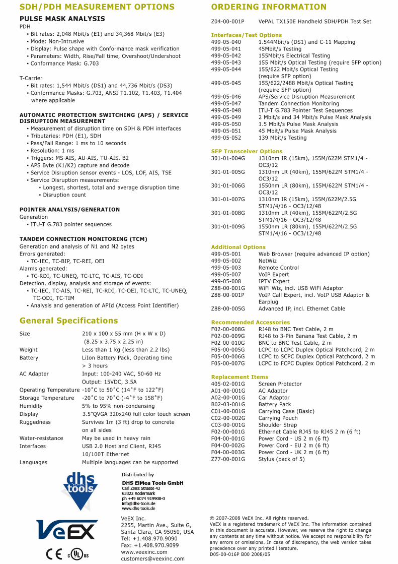