Embed Size (px)
Citation preview

Solar InvertersREACT-MTR-1PHQuick Installation Guide

2
1. Main componentsThe main components of the REACT-MTR-1PH are shown in the figure and described in the following table:
Main components01 Current sensor02 Power supply terminals03 Status LED04 Fixing spring for DIN rail05 RS485 line connection terminals
2. Supplied component list Components available in the kit Quantity
REACT-MTR-1PH 1
Technical documentation 1
02
03
01
0405
3
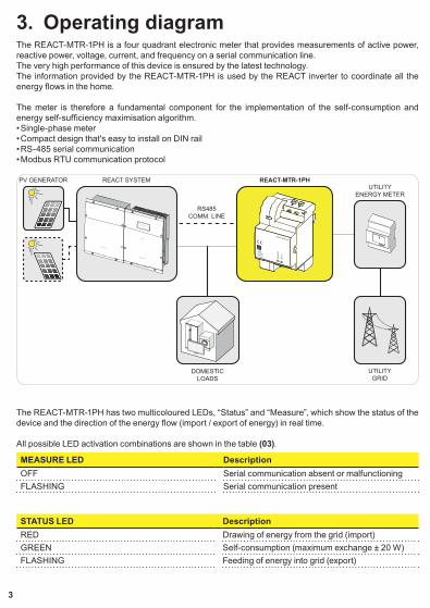
3. Operating diagramThe REACT-MTR-1PH is a four quadrant electronic meter that provides measurements of active power, reactive power, voltage, current, and frequency on a serial communication line.The very high performance of this device is ensured by the latest technology.The information provided by the REACT-MTR-1PH is used by the REACT inverter to coordinate all the energy flows in the home.
The meter is therefore a fundamental component for the implementation of the self-consumption and energy self-sufficiency maximisation algorithm.• Single-phase meter • Compact design that's easy to install on DIN rail• RS-485 serial communication• Modbus RTU communication protocol
REACT
POWER ALARM GFI ESC UP DOWN ENTER
REACT-UNO
REACT-BATT
PV GENERATOR REACT SYSTEM
DOMESTICLOADS
RS485COMM. LINE
UTILITYENERGY METER
REACT-MTR-1PH
UTILITYGRID
The REACT-MTR-1PH has two multicoloured LEDs, “Status” and “Measure”, which show the status of the device and the direction of the energy flow (import / export of energy) in real time.
All possible LED activation combinations are shown in the table (03).
MEASURE LED DescriptionOFF Serial communication absent or malfunctioningFLASHING Serial communication present
STATUS LED DescriptionRED Drawing of energy from the grid (import)GREEN Self-consumption (maximum exchange ± 20 W)FLASHING Feeding of energy into grid (export)

4
4. Assembly InstructionsThe REACT-MTR-1PH is designed to be assembled on a DIN rail (UNI EN 50022) using the special snap-on device (04) on the back of the unit.
For correct assembly of the REACT-MTR-1PH on the DIN rail follow the procedure below:• Using a flathead screwdriver, remove the tab to release the snap-on device (A).• Fit the REACT-MTR-1PH onto the DIN rail (B).• Push the tab so as to secure the snap-on device (C).
CA
B
NOTE – D If installed outside or in non-residential buildings, the use of an outdoor box with IP54 or IP66 level protection is strongly recommended.
5
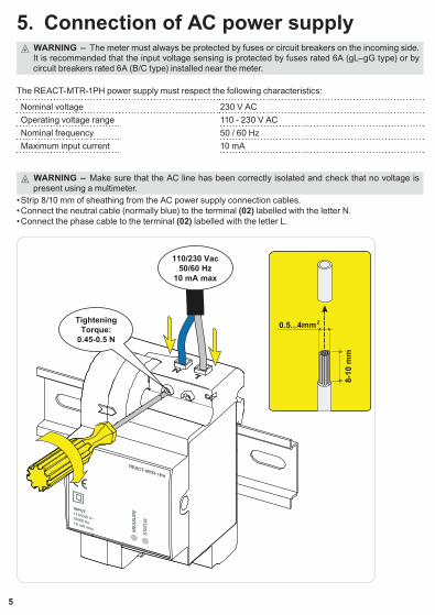
5. Connection of AC power supply WARNING – B The meter must always be protected by fuses or circuit breakers on the incoming side. It is recommended that the input voltage sensing is protected by fuses rated 6A (gL–gG type) or by circuit breakers rated 6A (B/C type) installed near the meter.
The REACT-MTR-1PH power supply must respect the following characteristics:
Nominal voltage 230 V ACOperating voltage range 110 - 230 V ACNominal frequency 50 / 60 HzMaximum input current 10 mA
WARNING – B Make sure that the AC line has been correctly isolated and check that no voltage is present using a multimeter.
• Strip 8/10 mm of sheathing from the AC power supply connection cables.• Connect the neutral cable (normally blue) to the terminal (02) labelled with the letter N.• Connect the phase cable to the terminal (02) labelled with the letter L.
8-10
mm
0.5...4mm2
110/230 Vac50/60 Hz
10 mA max
TighteningTorque:
0.45-0.5 N
6
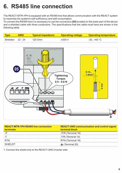
6. RS485 line connectionThe REACT-MTR-1PH is equipped with an RS485 line that allows communication with the REACT system to maximise the system's self-sufficiency and self-consumption.To connect the RS485 line it is necessary to use the connectors (05) located on the lower part of the device and a shielded cable with three conductors. The specifications that the cable must have are shown in the following table:
Type AWG Typical impedance Operating voltage Operating temperature
Shielded 22 - 24 120 Ohm ≥300 V -20...+60 °C
6 m
m
0.14...1.5mm 2
05Tightening
Torque:0.5 - 0.6 N
REACT-MTR-1PH RS485 line connection terminals
REACT-UNO communication and control signal terminal block
+T +T/R (Terminal 16)-T -T/R (Terminal 14)RTN RTN (Terminal 18)SHIELD(1) (Terminal 20)
1. Connect the shield only to the REACT-UNO Inverter side.
7
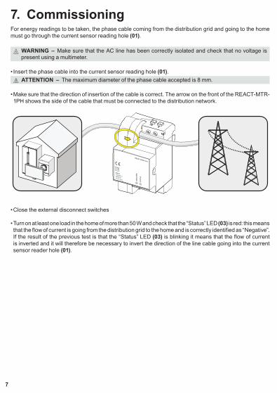
7. CommissioningFor energy readings to be taken, the phase cable coming from the distribution grid and going to the home must go through the current sensor reading hole (01).
WARNING – B Make sure that the AC line has been correctly isolated and check that no voltage is present using a multimeter.
• Insert the phase cable into the current sensor reading hole (01). ATTENTION – A The maximum diameter of the phase cable accepted is 8 mm.
• Make sure that the direction of insertion of the cable is correct. The arrow on the front of the REACT-MTR-1PH shows the side of the cable that must be connected to the distribution network.
• Close the external disconnect switches
• Turn on at least one load in the home of more than 50 W and check that the “Status” LED (03) is red: this means that the flow of current is going from the distribution grid to the home and is correctly identified as “Negative”. If the result of the previous test is that the “Status” LED (03) is blinking it means that the flow of current is inverted and it will therefore be necessary to invert the direction of the line cable going into the current sensor reader hole (01).
FIMER_REACT-MTR-1PH_Quick Installation Guide_EN_RevB
8
For more information please contact your local FIMER representative or visit:
fimer.com
We reserve the right to make technical changes or modify the contents of this document without prior notice. With regard to purchase orders, the agreed particulars shall prevail. FIMER does not accept any responsibility whatsoever for potential errors or possible lack of information in this document.
We reserve all rights in this document and in the subject matter and illustrations contained therein. Any reproduction, disclosure to third parties or utilization of its contents – in whole or in parts – is forbidden without prior written consent of FIMER. Copyright© 2020 FIMER. All rights reserved.
29/04/2021
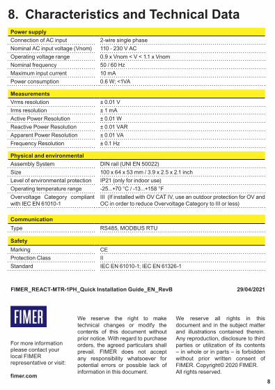
8. Characteristics and Technical DataPower supplyConnection of AC input 2-wire single phaseNominal AC input voltage (Vnom) 110 - 230 V ACOperating voltage range 0.9 x Vnom < V < 1.1 x VnomNominal frequency 50 / 60 HzMaximum input current 10 mAPower consumption 0.6 W; <1VA
MeasurementsVrms resolution ± 0.01 VIrms resolution ± 1 mAActive Power Resolution ± 0.01 WReactive Power Resolution ± 0.01 VARApparent Power Resolution ± 0.01 VAFrequency Resolution ± 0.1 Hz
Physical and environmentalAssembly System DIN rail (UNI EN 50022)Size 100 x 64 x 53 mm / 3.9 x 2.5 x 2.1 inchLevel of environmental protection IP21 (only for indoor use)Operating temperature range -25...+70 °C / -13...+158 °FOvervoltage Category compliant with IEC EN 61010-1
III (If installed with OV CAT IV, use an outdoor protection for OV and OC in order to reduce Overvoltage Category to III or less)
CommunicationType RS485, MODBUS RTU
SafetyMarking CEProtection Class IIStandard IEC EN 61010-1; IEC EN 61326-1