Embed Size (px)
Citation preview
Quick Start Guide for EV-MCS-LVDRV-Z Motor Drive Evaluation Platform Rev. 0.1
ANALOG DEVICES Page 1
Quick Start Guide for EV-MCS-LVDRV-Z Motor Drive Evaluation Platform
Rev. 0.1
Created: 12/17/2014 12:17 PM
Author: Dara O’Sullivan
Last Modified: 1/6/2015 12:06 PM
Modified by: Dara O’Sullivan
Quick Start Guide for EV-MCS-LVDRV-Z Motor Drive Evaluation Platform Rev. 0.1
ANALOG DEVICES Page 2
1 Contents
1 Contents ............................................................................................................................................ 2
2 Revision History ............................................................................................................................... 3
3 Overview ........................................................................................................................................... 4
3.1 System requirements .................................................................................................................. 4
4 Hardware Setup ................................................................................................................................. 4
4.1 Low Voltage Board ..................................................................................................................... 4
5 Software Setup .................................................................................................................................. 8
5.1 Programming with Serial Downloader ....................................................................................... 8
5.2 Programming with Segger J-Link ............................................................................................ 10
6 GUI Configuration .......................................................................................................................... 12
7 Running the Motor .......................................................................................................................... 14
8 Data Visualization ........................................................................................................................... 15
9 Support ............................................................................................................................................ 20
Quick Start Guide for EV-MCS-LVDRV-Z Motor Drive Evaluation Platform Rev. 0.1
ANALOG DEVICES Page 3
2 Revision History
Version Modified By Date Comments
0.1 Dara
O’Sullivan
1/6/2015 Document finalized.
Quick Start Guide for EV-MCS-LVDRV-Z Motor Drive Evaluation Platform Rev. 0.1
ANALOG DEVICES Page 4
3 Overview
This document will give a high level introduction to the EV-MCS-LVDRV motor control development
platform and will provide a step-by-step approach that will get a motor up running. Instructions are
provided on hardware setup, executable download, and graphical user interface (GUI) operation.
3.1 System requirements
Before you start working on the motor control platform, please make sure you have the hardware and
software listed below.
Required Hardware
- ADSP-CM408F EZ-KIT rev 0.2 (This is ordered separately from the EV-MCS-LVDRV-Z)
- EV-MCS-LVDRV-Z power board, including BLY171D-24V-6000 motor with encoder, power
supply and USB to serial cable
Optional Hardware
- Segger J-Link Lite debugger (This comes with the ADSP-CM408F Ezkit and can be used for
executable download, and code development, but is not necessary for basic setup)
Required Software
- ADSP-CM40x SW Enablement Package version 1.2.0 (available here :
http://sdk.analog.com/dw/sdks.aspx?file=ADUSC03 )
- ADIMonitor Graphical User Interface (available here: https://ez.analog.com/docs/DOC-11971 )
- Motor Control demo program executable and linker map file (also available here
https://ez.analog.com/docs/DOC-11971 )
Optional Software
- IAR Embedded Workbench (for code development, version 6.6 or higher)
- Segger J-Link Lite driver software
4 Hardware Setup
This section will describe how to setup the hardware. This only has to be performed once, when
bringing up a new platform.
4.1 Low Voltage Board
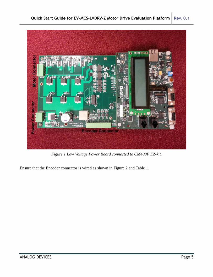
Connect the EZ-kit to the Power Board as shown in Figure 1. Make sure both Samtec connectors mate
completely. Also, note the location of Encoder, Power and Motor connectors.
Quick Start Guide for EV-MCS-LVDRV-Z Motor Drive Evaluation Platform Rev. 0.1
ANALOG DEVICES Page 5
Figure 1 Low Voltage Power Board connected to CM408F EZ-kit.
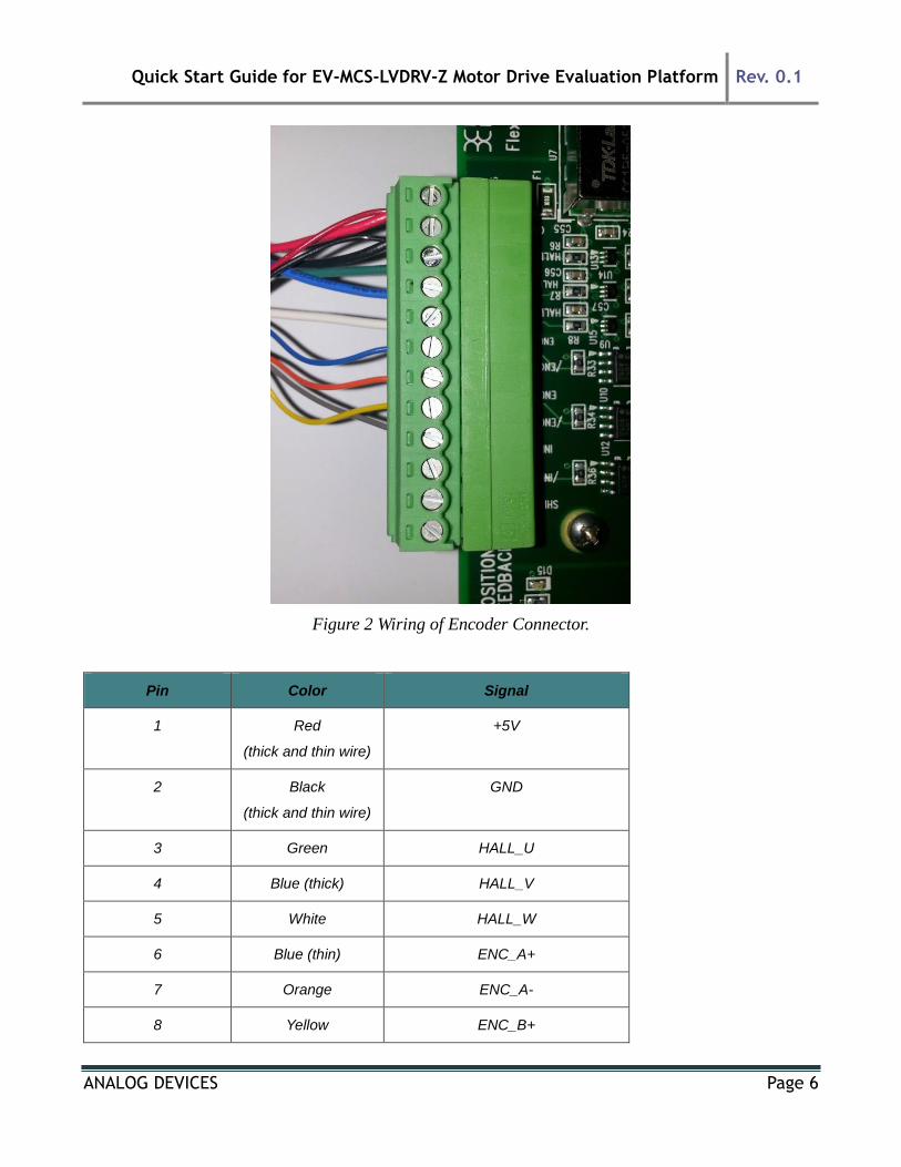
Ensure that the Encoder connector is wired as shown in Figure 2 and Table 1.
Quick Start Guide for EV-MCS-LVDRV-Z Motor Drive Evaluation Platform Rev. 0.1
ANALOG DEVICES Page 6
Figure 2 Wiring of Encoder Connector.
Pin Color Signal
1 Red
(thick and thin wire)
+5V
2 Black
(thick and thin wire)
GND
3 Green HALL_U
4 Blue (thick) HALL_V
5 White HALL_W
6 Blue (thin) ENC_A+
7 Orange ENC_A-
8 Yellow ENC_B+
Quick Start Guide for EV-MCS-LVDRV-Z Motor Drive Evaluation Platform Rev. 0.1
ANALOG DEVICES Page 7
9 Grey ENC_B-
10 NC INDEX+
11 NC INDEX-
12 NC Shield
Table 1 Encoder Connector
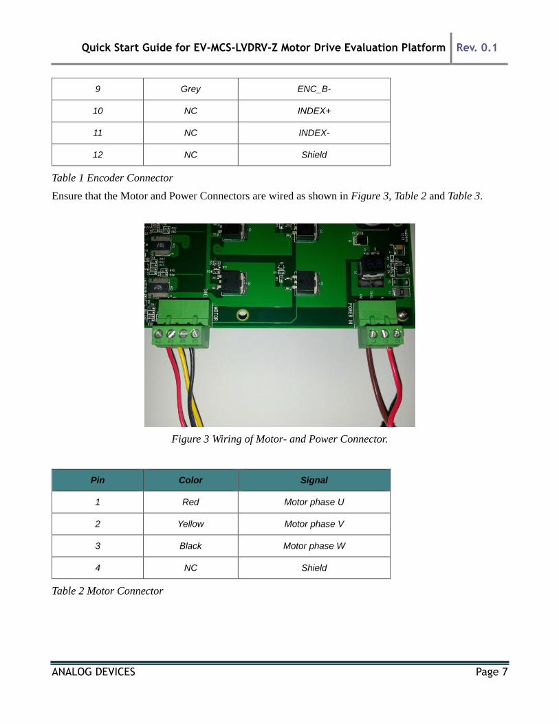
Ensure that the Motor and Power Connectors are wired as shown in Figure 3, Table 2 and Table 3.
Figure 3 Wiring of Motor- and Power Connector.
Pin Color Signal
1 Red Motor phase U
2 Yellow Motor phase V
3 Black Motor phase W
4 NC Shield
Table 2 Motor Connector
Quick Start Guide for EV-MCS-LVDRV-Z Motor Drive Evaluation Platform Rev. 0.1
ANALOG DEVICES Page 8
Pin Color Signal
1 Brown GND
2 NC Shield
3 Red +24V
Table 3 Power Connector
5 Software Setup
The software setup steps are as follows:
1. Download and install the ADSP-CM40x SW Enablement Package version 1.2.0 from the link
shown previously in “SW Requirements”. This includes the serial boot-loader which is needed
for download of the executable to the processor.
2. Download and install the GUI from the Engineer Zone link provided in “SW Requirements”.
This requires the .NET framework to be on the PC and it will prompt the user to download this
if it is not detected.
3. Download the motor control demo executable program from the Engineer Zone link provided in
“SW Requirements” and program this to the processor board (ADSP-CM408 EZkit).
The first two steps are fairly self-explanatory. The third step – programming of the executable to the
processor – can be carried out in two alternate ways. These are detailed in this section.
5.1 Programming with Serial Downloader
The serial downloader (“wsd.exe”) is provided as part of the ADSP-CM408 SW Enablement Package
and once this has been installed, assuming default installation directory structures, the downloader is
found in C:\Analog Devices\ADSP-CM40x\CM403F_CM408F_EZ-KIT\tool\UARTFlashProgrammer.
This method uses the MC_Demo.hex executable provided at the Engineer Zone link.
Steps:
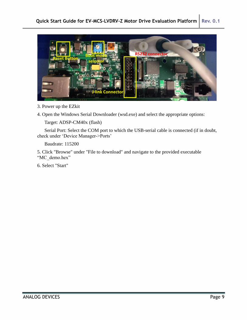
1. Connect the EZ-kit to the PC using the USB-UART cable: UART (RS-232) connector on the
EZkit, USB on the PC
2. Select Boot Mode 3 (UART Boot) on the EZkit using the selector switch P3 (adjacent to the
power connector)
Quick Start Guide for EV-MCS-LVDRV-Z Motor Drive Evaluation Platform Rev. 0.1
ANALOG DEVICES Page 9
3. Power up the EZkit
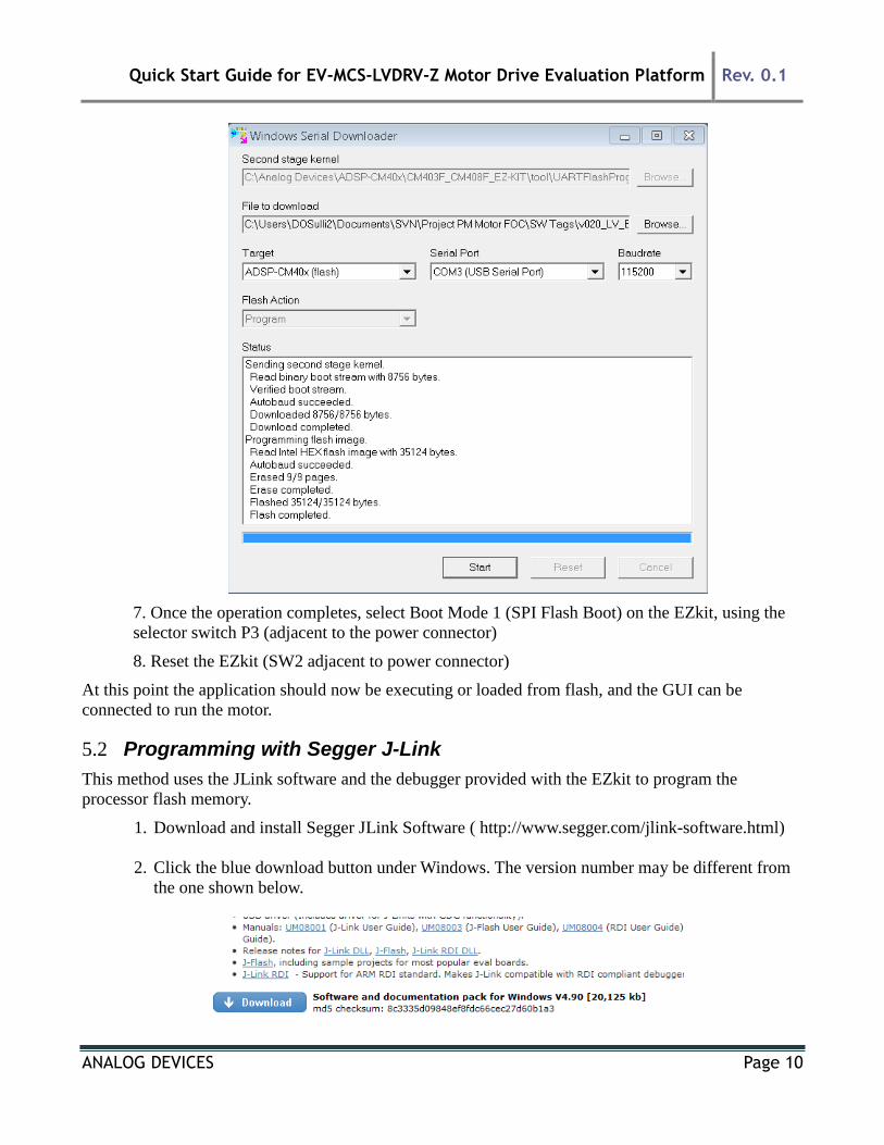
4. Open the Windows Serial Downloader (wsd.exe) and select the appropriate options:
Target: ADSP-CM40x (flash)
Serial Port: Select the COM port to which the USB-serial cable is connected (if in doubt,
check under ‘Device Manager->Ports’
Baudrate: 115200
5. Click "Browse" under "File to download" and navigate to the provided executable
“MC_demo.hex”
6. Select "Start"
RS232 connectorBoot modeselector
Reset Button
J-link Connector
Quick Start Guide for EV-MCS-LVDRV-Z Motor Drive Evaluation Platform Rev. 0.1
ANALOG DEVICES Page 10
7. Once the operation completes, select Boot Mode 1 (SPI Flash Boot) on the EZkit, using the
selector switch P3 (adjacent to the power connector)
8. Reset the EZkit (SW2 adjacent to power connector)
At this point the application should now be executing or loaded from flash, and the GUI can be
connected to run the motor.
5.2 Programming with Segger J-Link
This method uses the JLink software and the debugger provided with the EZkit to program the
processor flash memory.
1. Download and install Segger JLink Software ( http://www.segger.com/jlink-software.html)
2. Click the blue download button under Windows. The version number may be different from
the one shown below.
Quick Start Guide for EV-MCS-LVDRV-Z Motor Drive Evaluation Platform Rev. 0.1
ANALOG DEVICES Page 11
3. Enter your Segger JLink Lite serial number in the next box. This number is printed on the
microcontroller on the debugger board.
4. Click the confirmation box on the next screen, download the software and install (default
location is C:\Program Files(x86)\Segger)
5. Connect the JLink to the PC USB port and the other end to the 20 pin connector on the
CM40x board.
6. The PC will start automatically start installing drivers for your Jlink . Let it complete and
turn on power to the EZkit.
7. Turn on power to the CM408x board.
8. Go to the location where Segger was installed and click on JLink .exe. In this case it is in:
C:\Program Files (x86)\SEGGER\JLink_V490 (The version number and folder name may
be different to the one in this example.)
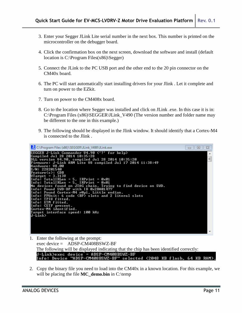
9. The following should be displayed in the Jlink window. It should identify that a Cortex-M4
is connected to the Jlink .
1. Enter the following at the prompt:
exec device = ADSP-CM408BSWZ-BF
The following will be displayed indicating that the chip has been identified correctly:
2. Copy the binary file you need to load into the CM40x in a known location. For this example, we
will be placing the file MC_demo.bin in C:\temp
Quick Start Guide for EV-MCS-LVDRV-Z Motor Drive Evaluation Platform Rev. 0.1
ANALOG DEVICES Page 12
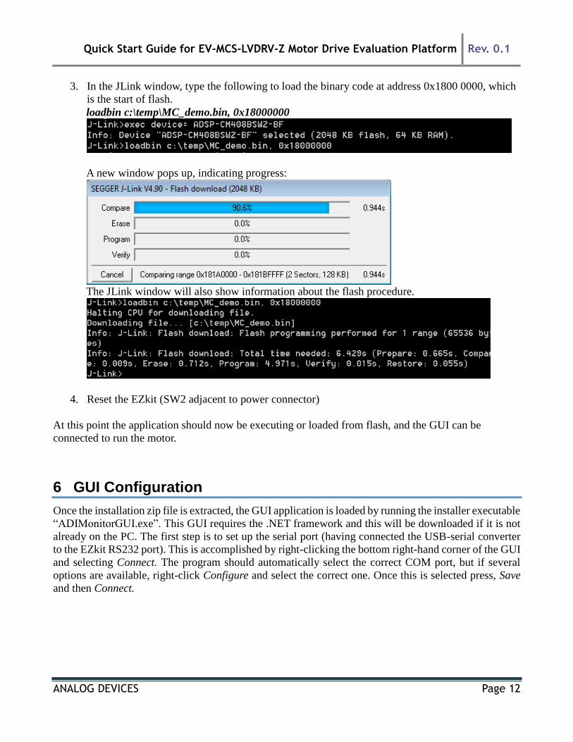
3. In the JLink window, type the following to load the binary code at address 0x1800 0000, which
is the start of flash.
loadbin c:\temp\MC_demo.bin, 0x18000000
A new window pops up, indicating progress:
The JLink window will also show information about the flash procedure.
4. Reset the EZkit (SW2 adjacent to power connector)
At this point the application should now be executing or loaded from flash, and the GUI can be
connected to run the motor.
6 GUI Configuration
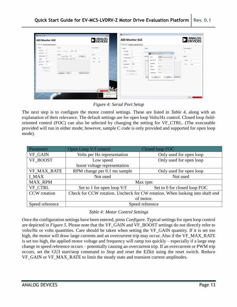
Once the installation zip file is extracted, the GUI application is loaded by running the installer executable
“ADIMonitorGUI.exe”. This GUI requires the .NET framework and this will be downloaded if it is not
already on the PC. The first step is to set up the serial port (having connected the USB-serial converter
to the EZkit RS232 port). This is accomplished by right-clicking the bottom right-hand corner of the GUI
and selecting Connect. The program should automatically select the correct COM port, but if several
options are available, right-click Configure and select the correct one. Once this is selected press, Save
and then Connect.
Quick Start Guide for EV-MCS-LVDRV-Z Motor Drive Evaluation Platform Rev. 0.1
ANALOG DEVICES Page 13
Figure 4: Serial Port Setup
The next step is to configure the motor control settings. These are listed in Table 4, along with an
explanation of their relevance. The default settings are for open loop Volts/Hz control. Closed loop field-
oriented control (FOC) can also be selected by changing the setting for VF_CTRL. (The executable
provided will run in either mode; however, sample C code is only provided and supported for open loop
mode).
Parameter Open Loop V/f control Closed loop FOC
VF_GAIN Volts per Hz representation Only used for open loop
VF_BOOST Low speed
boost voltage representation
Only used for open loop
VF_MAX_RATE RPM change per 0.1 ms sample Only used for open loop
I_MAX Not used Not used
MAX_RPM Max rpm
VF_CTRL Set to 1 for open loop V/f Set to 0 for closed loop FOC
CCW rotation Check for CCW rotation. Uncheck for CW rotation. When looking into shaft end
of motor.
Speed reference Speed reference
Table 4: Motor Control Settings
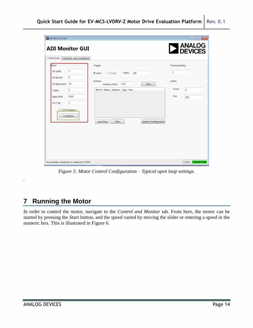
Once the configuration settings have been entered, press Configure. Typical settings for open loop control
are depicted in Figure 5. Please note that the VF_GAIN and VF_BOOST settings do not directly refer to
volts/Hz or volts quantities. Care should be taken when setting the VF_GAIN quantity. If it is set too
high, the motor will draw large currents and an overcurrent trip may occur. Also if the VF_MAX_RATE
is set too high, the applied motor voltage and frequency will ramp too quickly – especially if a large step
change in speed reference occurs – potentially causing an overcurrent trip. If an overcurrent or PWM trip
occurs, set the GUI start/stop command to Stop and reset the EZkit using the reset switch. Reduce
VF_GAIN or VF_MAX_RATE to limit the steady state and transient current amplitudes.
Quick Start Guide for EV-MCS-LVDRV-Z Motor Drive Evaluation Platform Rev. 0.1
ANALOG DEVICES Page 14
Figure 5: Motor Control Configuration – Typical open loop settings.
.
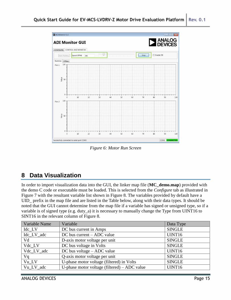
7 Running the Motor
In order to control the motor, navigate to the Control and Monitor tab. From here, the motor can be
started by pressing the Start button, and the speed varied by moving the slider or entering a speed in the
numeric box. This is illustrated in Figure 6.
Quick Start Guide for EV-MCS-LVDRV-Z Motor Drive Evaluation Platform Rev. 0.1
ANALOG DEVICES Page 15
Figure 6: Motor Run Screen
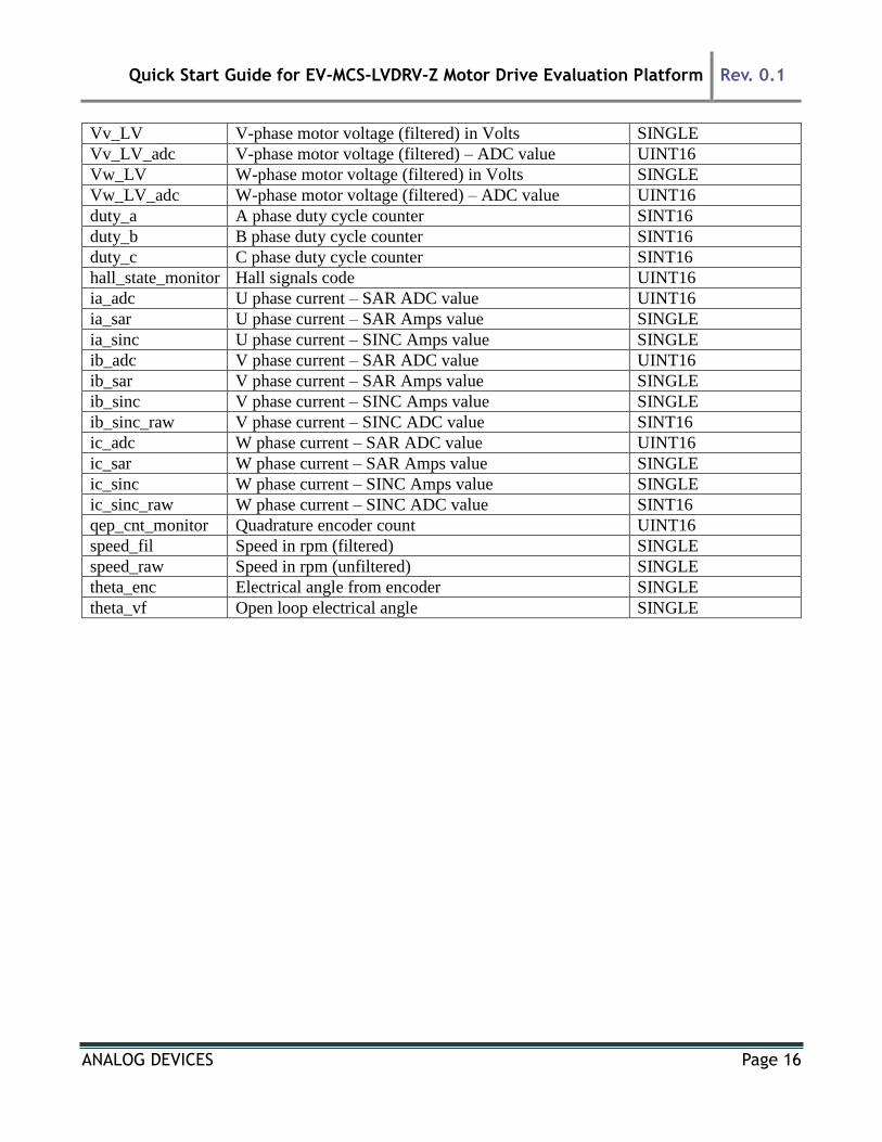
8 Data Visualization
In order to import visualization data into the GUI, the linker map file (MC_demo.map) provided with
the demo C code or executable must be loaded. This is selected from the Configure tab as illustrated in
Figure 7 with the resultant variable list shown in Figure 8. The variables provided by default have a
UID_ prefix in the map file and are listed in the Table below, along with their data types. It should be
noted that the GUI cannot determine from the map file if a variable has signed or unsigned type, so if a
variable is of signed type (e.g. duty_a) it is necessary to manually change the Type from UINT16 to
SINT16 in the relevant column of Figure 8.
Variable Name Variable Data Type
Idc_LV DC bus current in Amps SINGLE
Idc_LV_adc DC bus current – ADC value UINT16
Vd D-axis motor voltage per unit SINGLE
Vdc_LV DC bus voltage in Volts SINGLE
Vdc_LV_adc DC bus voltage – ADC value UINT16
Vq Q-axis motor voltage per unit SINGLE
Vu_LV U-phase motor voltage (filtered) in Volts SINGLE
Vu_LV_adc U-phase motor voltage (filtered) – ADC value UINT16
Quick Start Guide for EV-MCS-LVDRV-Z Motor Drive Evaluation Platform Rev. 0.1
ANALOG DEVICES Page 16
Vv_LV V-phase motor voltage (filtered) in Volts SINGLE
Vv_LV_adc V-phase motor voltage (filtered) – ADC value UINT16
Vw_LV W-phase motor voltage (filtered) in Volts SINGLE
Vw_LV_adc W-phase motor voltage (filtered) – ADC value UINT16
duty_a A phase duty cycle counter SINT16
duty_b B phase duty cycle counter SINT16
duty_c C phase duty cycle counter SINT16
hall_state_monitor Hall signals code UINT16
ia_adc U phase current – SAR ADC value UINT16
ia_sar U phase current – SAR Amps value SINGLE
ia_sinc U phase current – SINC Amps value SINGLE
ib_adc V phase current – SAR ADC value UINT16
ib_sar V phase current – SAR Amps value SINGLE
ib_sinc V phase current – SINC Amps value SINGLE
ib_sinc_raw V phase current – SINC ADC value SINT16
ic_adc W phase current – SAR ADC value UINT16
ic_sar W phase current – SAR Amps value SINGLE
ic_sinc W phase current – SINC Amps value SINGLE
ic_sinc_raw W phase current – SINC ADC value SINT16
qep_cnt_monitor Quadrature encoder count UINT16
speed_fil Speed in rpm (filtered) SINGLE
speed_raw Speed in rpm (unfiltered) SINGLE
theta_enc Electrical angle from encoder SINGLE
theta_vf Open loop electrical angle SINGLE

Quick Start Guide for EV-MCS-LVDRV-Z Motor Drive Evaluation Platform Rev. 0.1
ANALOG DEVICES Page 17
Figure 7: Load Map file for Data Visualization
Figure 8: Visualization Variables
In order to select a variable for plotting, selection is by means of the check-box in the Plot column. The

Quick Start Guide for EV-MCS-LVDRV-Z Motor Drive Evaluation Platform Rev. 0.1
ANALOG DEVICES Page 18
variable can be plotted in Plot 1 or Plot 2 (see Figure 6). There are certain constraints on the number of
bytes and buffers that can be streamed using the GUI. The program will limit the total buffer size to
1.7k bytes. The number of variables plotted can be increased by reducing the buffer size, which is
maximum 200, although a total maximum selected variable size of 8 bytes is allowed (e.g. 2xSINGLE
or 4xINT16, or 1xSINGLE+2xINT16 etc).
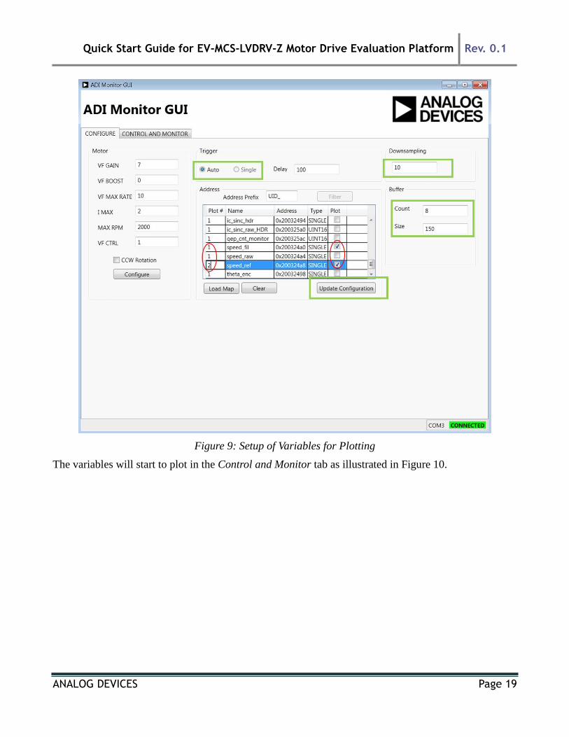
The steps to prepare for plotting of variables are (refer to Figure 9):
1. Select all of the variables to be plotted and whether each one is to be on Plot 1 or Plot 2, bearing
in mind the maximum buffer memory size (1.7k) and the maximum byte count per buffer (8).
2. Down Sampling factor – the buffer time slice length equals the PWM switching period x Down
Sampling ratio, so for a down sampling ratio of 1, the sampling period will be 100s, and with a
buffer length of 200, the plot time slices will be of 20ms length. To look at longer time slices,
increase the down sampling factor.
3. Press Update Configuration
4. On the Control and Monitor tab, press Start Plotting.
5. If the variables are to be changed, press Stop Plotting and return to the Configure tab to change
the configured variables.
Quick Start Guide for EV-MCS-LVDRV-Z Motor Drive Evaluation Platform Rev. 0.1
ANALOG DEVICES Page 19
Figure 9: Setup of Variables for Plotting
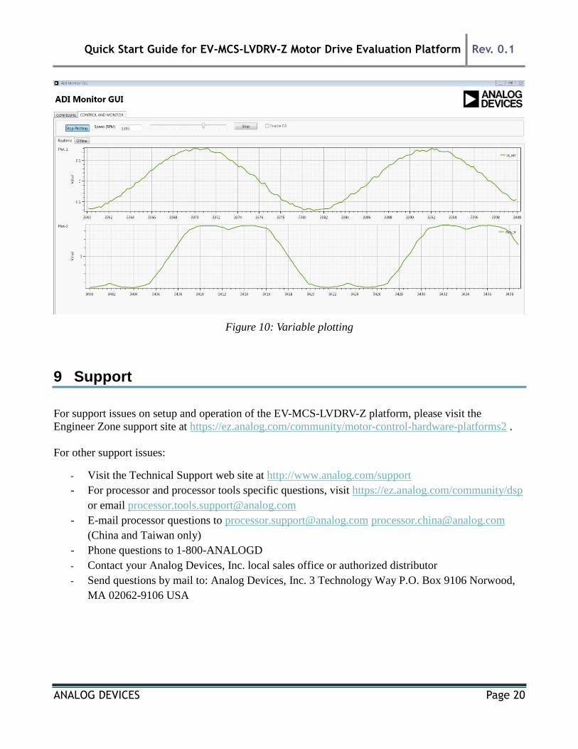
The variables will start to plot in the Control and Monitor tab as illustrated in Figure 10.
Quick Start Guide for EV-MCS-LVDRV-Z Motor Drive Evaluation Platform Rev. 0.1
ANALOG DEVICES Page 20
Figure 10: Variable plotting
9 Support
For support issues on setup and operation of the EV-MCS-LVDRV-Z platform, please visit the
Engineer Zone support site at https://ez.analog.com/community/motor-control-hardware-platforms2 .
For other support issues:
- Visit the Technical Support web site at http://www.analog.com/support
- For processor and processor tools specific questions, visit https://ez.analog.com/community/dsp
or email [email protected]
- E-mail processor questions to [email protected] [email protected]
(China and Taiwan only)
- Phone questions to 1-800-ANALOGD
- Contact your Analog Devices, Inc. local sales office or authorized distributor
- Send questions by mail to: Analog Devices, Inc. 3 Technology Way P.O. Box 9106 Norwood,
MA 02062-9106 USA