Embed Size (px)
Citation preview
www.mellanox.com Mellanox Technologies Confidential
Nutanix and Mellanox SN2010 CLI Deployment
Quick Start Guide
Rev 1.0

Doc #: MLNX-15-xxxx Mellanox Technologies Confidential 2
Mellanox Technologies
350 Oakmead Parkway Suite 100
Sunnyvale, CA 94085
U.S.A.
www.mellanox.com
Tel: (408) 970-3400
Fax: (408) 970-3403
© Copyright 2019. Mellanox Technologies Ltd. All Rights Reserved.
Mellanox®, Mellanox logo, Mellanox Open Ethernet®, LinkX®, Mellanox Spectrum®, Mellanox Virtual Modular
Switch®, MetroDX®, MetroX®, MLNX-OS®, ONE SWITCH. A WORLD OF OPTIONS®, Open Ethernet logo,
Spectrum logo, Switch-IB®, SwitchX®, UFM®, and Virtual Protocol Interconnect® are registered trademarks of
Mellanox Technologies, Ltd.
For the complete and most updated list of Mellanox trademarks, visit http://www.mellanox.com/page/trademarks.
All other trademarks are property of their respective owners.
NOTE:
THIS HARDWARE, SOFTWARE OR TEST SUITE PRODUCT PRODUCT(S) AND ITS RELATED
DOCUMENTATION ARE PROVIDED BY MELLANOX TECHNOLOGIES AS-IS WITH ALL FAULTS OF ANY
KIND AND SOLELY FOR THE PURPOSE OF AIDING THE CUSTOMER IN TESTING APPLICATIONS THAT
USE THE PRODUCTS IN DESIGNATED SOLUTIONS. THE CUSTOMER'S MANUFACTURING TEST
ENVIRONMENT HAS NOT MET THE STANDARDS SET BY MELLANOX TECHNOLOGIES TO FULLY
QUALIFY THE PRODUCT(S) AND/OR THE SYSTEM USING IT. THEREFORE, MELLANOX TECHNOLOGIES
CANNOT AND DOES NOT GUARANTEE OR WARRANT THAT THE PRODUCTS WILL OPERATE WITH THE
HIGHEST QUALITY. ANY EXPRESS OR IMPLIED WARRANTIES, INCLUDING, BUT NOT LIMITED TO, THE
IMPLIED WARRANTIES OF MERCHANTABILITY, FITNESS FOR A PARTICULAR PURPOSE AND
NONINFRINGEMENT ARE DISCLAIMED. IN NO EVENT SHALL MELLANOX BE LIABLE TO CUSTOMER OR
ANY THIRD PARTIES FOR ANY DIRECT, INDIRECT, SPECIAL, EXEMPLARY, OR CONSEQUENTIAL
DAMAGES OF ANY KIND (INCLUDING, BUT NOT LIMITED TO, PAYMENT FOR PROCUREMENT OF
SUBSTITUTE GOODS OR SERVICES; LOSS OF USE, DATA, OR PROFITS; OR BUSINESS INTERRUPTION)
HOWEVER CAUSED AND ON ANY THEORY OF LIABILITY, WHETHER IN CONTRACT, STRICT LIABILITY,
OR TORT (INCLUDING NEGLIGENCE OR OTHERWISE) ARISING IN ANY WAY FROM THE USE OF THE
PRODUCT(S) AND RELATED DOCUMENTATION EVEN IF ADVISED OF THE POSSIBILITY OF SUCH
DAMAGE.

3 Mellanox Technologies Confidential Rev 1.0
Table of Contents
1 Overview .......................................................................................................................................... 4
2 Setup ................................................................................................................................................ 5
2.1 Mellanox MLAG-Based Leaf-Spine Topology ........................................................................ 5
2.2 Nutanix and Mellanox Spectrum SN2010 MLAG ................................................................... 6
3 Configuration ................................................................................................................................... 7
3.1 General configuration ............................................................................................................. 7
3.2 Configure IPL .......................................................................................................................... 7
3.3 MLAG VIP and system MAC .................................................................................................. 8
3.4 MLAG Ports (Downlinks) ........................................................................................................ 8
3.5 Switch Uplinks ........................................................................................................................ 9
3.6 L2 Uplinks - MPo .................................................................................................................. 10
3.7 Spine Switch Routing Configuration ..................................................................................... 11
3.8 MAGP Configuration ............................................................................................................. 12
3.9 Uplinks and BGP Routing ..................................................................................................... 13
3.10 Nutanix AHV LAG (bond) Configuration to LACP ................................................................ 14
4 Configuration Verification ............................................................................................................ 15
4.1 MLAG Status ........................................................................................................................ 15
4.2 MLAG Port-channels (MPo) Status ...................................................................................... 16
4.3 MLAG Ports VLAN membership verification ........................................................................ 17
4.4 MLAG-VIP status .................................................................................................................. 19
4.5 MAGP status ......................................................................................................................... 20
4.6 BGP Routing status .............................................................................................................. 22

Rev 1.0 Mellanox Technologies Confidential 4
1 Overview
Mellanox switches allow you to create a network fabric that offers predictable, low-latency
switching while achieving maximum throughput and linear scalability. Combined with the
features and intelligence of the Mellanox ONYX operating system (OS), multilink
aggregation groups (MLAGs) create a highly available L2 fabric across Mellanox
networking appliances to ensure that you can meet even the most stringent SLAs.
MLAGs aggregate ports across multiple physical switches. Configuring link aggregation
between physical switch ports and Nutanix appliances enables the Nutanix Controller Virtual
Machine (CVM) to utilize all pNICs and actively load balances user VMs on TCP streams.
This capability is a key advantage, particularly in all-flash clusters.
Mellanox ONYX operation system provides a streamlined deployment model with a full
documentation set to facilitate networking configurations ranging from basic to advanced.
Mellanox Spectrum ASIC (application-specific integrated circuit) delivers 100 GbE port
speed with the industry’s lowest port-to-port latency (approximately 300 ns, or about 0.6 us
leaf to spine).
In the examples that follow, we deploy the leaf-spine topology using MLAGs. Managing and
updating each switch independently with MLAGs mitigates the single point of failure that
typically results from employing stacking techniques within the switches.
MLAGs do not disable links to prevent network loops, as with STP. Although STP is still
enabled to prevent loops during switch startup, once the switch is initialized and in a
forwarding state, all MLAG Ports’ STP states are synced and they send the same BPDU so
they are considered as a single link from the connected devices point of view. This ensures
that all links are available to pass traffic and benefit from the aggregated bandwidth.

5 Mellanox Technologies Confidential Rev 1.0
spine
1
spine
2
leaf1 leaf2 leafXleafX
+1
Nutanix
Nutanix
…
Nutanix
Nutanix
Nutanix
Nutanix
Nutanix
Nutanix
HCI
DC network
2 Setup
2.1 Mellanox MLAG-Based Leaf-Spine Topology
In this setup, we demonstrate how to achieve a Mellanox MLAG-based leaf-spine topology
utilizing Mellanox SN2000 Series switches. This reference architecture consists of Mellanox
SN2010 switches (18 ports x 10/25Gbe + 4 ports x 40/100Gbe) as leaf switches and SN2700
(32 ports x 100Gbe) as spine switches.
The routing between VLANs can be done by the spine switches (which also operate in
MLAG for the downlinks) or at the layer above the spines.

Rev 1.0 Mellanox Technologies Confidential 6
2.2 Nutanix and Mellanox Spectrum SN2010 MLAG
In the diagram that will be used for this guide, there are four Nutanix Nodes that are
connected using an Active-Active LACP bond to a pair of Mellanox SN2010 switches that
configured in MLAG.
Prerequisites:
• Bring-up your Nutanix cluster before starting the Switch configuration flow.
• Configure management IP addresses for both switches (Statically or DHCP).
NOTE:
SN2700 spine switches aren’t displayed in this diagram (can be seen in general diagrams)
since the focus of the guide is on MLAG configuration on SN2010 leaf switches.

7 Mellanox Technologies Confidential Rev 1.0
3 Configuration
The following section details Mellanox MLAG configuration using CLI. You can find out
more about MLAG configuration at Mellanox community website.
NOTE:
Before you start, make sure that both switches have the same software version. Run the
show version command to verify.
In addition, we recommend upgrading both switches to the latest ONYX software
release.
3.1 General configuration
Run the following commands on both switches:
SW-1 (config) # lacp SW-1 (config) # ip routing SW-1 (config) # protocol mlag
SW-2 (config) # lacp SW-2 (config) # ip routing SW-2 (config) # protocol mlag
Port speed should be set if towards the Nutanix nodes in case they support 10G (switch
default is 25G)
SW-1 (config) # interface ethernet 1/1-1/4 speed 10G force
SW-2 (config) # interface ethernet 1/1-1/4 speed 10G force
3.2 Configure IPL
Configure the Inter-Peer link (IPL), a LAG between switches that maintains state
information, over an MLAG (port channel) with ID 1. For high availability, we recommend
having more than one physical link within this LAG. In this example, we are configuring the
IPL on ports 1/21 and 1/22 of two SN2010 switches. All VLANs are open on these ports.
The example uses VLAN 4000 for configuring the IP address.
Run the following commands on both switches:
SW-1 (config) # interface port-channel 1
SW-1 (config interface port-channel 1) # exit
SW-1 (config) # interface ethernet 1/21-1/22 channel-group 1 mode active
SW-1 (config) # vlan 4000
SW-1 (config vlan 4000) # exit
SW-1 (config) # interface vlan 4000
SW-1 (config interface vlan 4000 ) # exit
SW-1 (config) # interface port-channel 1 ipl 1
SW-2 (config) # interface port-channel 1
SW-2 (config interface port-channel 1) # exit
SW-2 (config) # interface ethernet 1/21-1/22 channel-group 1 mode active
SW-2 (config) # vlan 4000
SW-2 (config vlan 4000) # exit
SW-2 (config) # interface vlan 4000
SW-2 (config interface vlan 4000 ) # exit
SW-2 (config) # interface port-channel 1 ipl 1

Rev 1.0 Mellanox Technologies Confidential 8
Configure the IP address for the IPL link on both switches on VLAN 4000. Enter the
following commands on SW-1 and SW-2:
SW-1 (config) # interface vlan 4000
SW-1 (config interface vlan 4000) # ip address 10.10.10.1 255.255.255.0
SW-1 (config interface vlan 4000) # ipl 1 peer-address 10.10.10.2
SW-2 (config) # interface vlan 4000
SW-2 (config interface vlan 4000) # ip address 10.10.10.2 255.255.255.0
SW-2 (config interface vlan 4000) # ipl 1 peer-address 10.10.10.1
3.3 MLAG VIP and system MAC
The MLAG VIP (virtual IP) is important for retrieving peer information.
Configure the following on both switches:
SW-1 (config) # mlag-vip my-mlag-vip-domain ip 10.209.28.200 /24 force
SW-1 (config) # mlag system-mac 00:00:5E:00:01:5D
SW-1 (config) # no mlag shutdown
SW-2 (config) # mlag-vip my-mlag-vip-domain ip 10.209.28.200 /24 force
SW-2 (config) # mlag system-mac 00:00:5E:00:01:5D
SW-2 (config) # no mlag shutdown
3.4 MLAG Ports (Downlinks)
In this example, there are 4 MLAG ports—one for each host. Host A is connected to mlag-
port-channel 1 (MPo1), host B is connected to MPo2, host C is connected to MPo3 and host
D to MPo4.
Configure the following on both switches:
SW-1 (config) # interface mlag-port-channel 1-4
SW-1 (config interface port-channel 1-4) # mtu 9216
SW-1 (config) # interface ethernet 1/1 mlag-channel-group 1 mode active
SW-1 (config) # interface ethernet 1/2 mlag-channel-group 2 mode active
SW-1 (config) # interface ethernet 1/3 mlag-channel-group 3 mode active
SW-1 (config) # interface ethernet 1/4 mlag-channel-group 4 mode active
SW-1 (config) # vlan 1-4
SW-1 (config) # interface mlag-port-channel 1 switchport mode hybrid
SW-1 (config) # interface mlag-port-channel 2 switchport mode hybrid
SW-1 (config) # interface mlag-port-channel 3 switchport mode hybrid
SW-1 (config) # interface mlag-port-channel 4 switchport mode hybrid
SW-1 (config) # interface mlag-port-channel 1 switchport hybrid allowed-vlan [x,y..]
SW-1 (config) # interface mlag-port-channel 2 switchport hybrid allowed-vlan [x,y..]
SW-1 (config) # interface mlag-port-channel 3 switchport hybrid allowed-vlan [x,y..]
NOTE:
The MLAG-VIP address should be within the same subnet as the management interface
(mgmt0).
MLAG-VIP name should be unique per mlag switch pair.
MLAG system-mac should be unique per mlag switch pair.
NOTE:
In case that not an LACP bond used, there is no need to configure any MLAG Ports
(MPo) on the switches as the bond will use Active-Backup mode.

9 Mellanox Technologies Confidential Rev 1.0
SW-1 (config) # interface mlag-port-channel 4 switchport hybrid allowed-vlan [x,y..]
SW-1 (config) # interface mlag-port-channel 1-4 no shutdown
SW-2 (config) # interface mlag-port-channel 1-4
SW-2 (config interface port-channel 1-4) # mtu 9216
SW-2 (config) # interface ethernet 1/1 mlag-channel-group 1 mode active
SW-2 (config) # interface ethernet 1/2 mlag-channel-group 2 mode active
SW-2 (config) # interface ethernet 1/3 mlag-channel-group 3 mode active
SW-2 (config) # interface ethernet 1/4 mlag-channel-group 4 mode active
SW-2 (config) # vlan 1-4
SW-2 (config) # interface mlag-port-channel 1 switchport mode hybrid
SW-2 (config) # interface mlag-port-channel 2 switchport mode hybrid
SW-2 (config) # interface mlag-port-channel 3 switchport mode hybrid
SW-2 (config) # interface mlag-port-channel 4 switchport mode hybrid
SW-2 (config) # interface mlag-port-channel 1 switchport hybrid allowed-vlan [x,y..]
SW-2 (config) # interface mlag-port-channel 2 switchport hybrid allowed-vlan [x,y..]
SW-2 (config) # interface mlag-port-channel 3 switchport hybrid allowed-vlan [x,y..]
SW-2 (config) # interface mlag-port-channel 4 switchport hybrid allowed-vlan [x,y..]
SW-2 (config) # interface mlag-port-channel 1-4 no shutdown
3.5 Switch Uplinks
L2 ports are used as MLAG switch uplinks towards the spine switches. These ports need to
be aggregated into a single MLAG port (Mpo) and MLAG needs to be configured on the
spine switches.
Each MLAG switch has two uplinks towards the spine switches, port numbers 1/19 and 1/20.
MAGP will be used as the host’s (VM’s) Gateways to communicate with outer networks.
Each VLAN must have its own MAGP instance to be able to communicate with other
VLANs or external networks.

Rev 1.0 Mellanox Technologies Confidential 10
3.6 L2 Uplinks - MPo
Configure the following commands on both leaf switches:
SW-1 (config) # interface mlag-port-channel 10
SW-1 (config interface port-channel 10) # mtu 9216
SW-1 (config) # interface ethernet 1/19-1/20 mlag-channel-group 10 mode active
SW-1 (config) # interface mlag-port-channel 10 switchport mode hybrid
SW-1 (config) # interface mlag-port-channel 10 switchport hybrid allowed-vlan
[x,y..]
SW-1 (config) # interface mlag-port-channel 10 no shutdown
SW-2 (config) # interface mlag-port-channel 10
SW-2 (config interface port-channel 10) # mtu 9216
SW-2 (config) # interface ethernet 1/19-1/20 mlag-channel-group 10 mode active
SW-2 (config) # interface mlag-port-channel 10 switchport mode hybrid
SW-2 (config) # interface mlag-port-channel 10 switchport hybrid allowed-vlan
[x,y..]
SW-2 (config) # interface mlag-port-channel 10 no shutdown
Example of a Core/Spine switch connection:

11 Mellanox Technologies Confidential Rev 1.0
3.7 Spine Switch Routing Configuration
In this example, we use L3 router ports uplinks towards the DC network. The Routing
protocol assumed is BGP.
Multi-Active Gateway Protocol (MAGP) will be used as the host’s (VM’s) Gateways to
communicate with outer networks. Each VLAN must have its own MAGP instance to be
able to communicate with other VLANs or external networks. The configuration is done on
the leaf switches level.
NOTE:
The spines MLAG configuration should be done in the same way as done on the leaf
switches.
NOTE:
The bellow example can be configured on the leafs switches as well, in case your leafs
are connected directly to the DC network and routing is desired on the leafs.
Rev 1.0 Mellanox Technologies Confidential 12
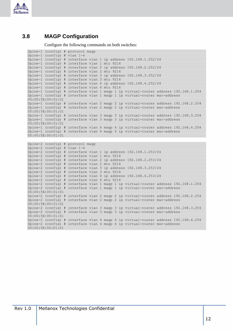
3.8 MAGP Configuration
Configure the following commands on both switches:
Spine-1 (config) # protocol magp
Spine-1 (config) # vlan 1-4
Spine-1 (config) # interface vlan 1 ip address 192.168.1.252/24
Spine-1 (config) # interface vlan 1 mtu 9216
Spine-1 (config) # interface vlan 2 ip address 192.168.2.252/24
Spine-1 (config) # interface vlan 2 mtu 9216
Spine-1 (config) # interface vlan 3 ip address 192.168.3.252/24
Spine-1 (config) # interface vlan 3 mtu 9216
Spine-1 (config) # interface vlan 4 ip address 192.168.4.252/24
Spine-1 (config) # interface vlan 4 mtu 9216
Spine-1 (config) # interface vlan 1 magp 1 ip virtual-router address 192.168.1.254
Spine-1 (config) # interface vlan 1 magp 1 ip virtual-router mac-address
00:00:5E:00:01:01
Spine-1 (config) # interface vlan 2 magp 2 ip virtual-router address 192.168.2.254
Spine-1 (config) # interface vlan 2 magp 2 ip virtual-router mac-address
00:00:5E:00:01:01
Spine-1 (config) # interface vlan 3 magp 3 ip virtual-router address 192.168.3.254
Spine-1 (config) # interface vlan 3 magp 3 ip virtual-router mac-address
00:00:5E:00:01:01
Spine-1 (config) # interface vlan 4 magp 4 ip virtual-router address 192.168.4.254
Spine-1 (config) # interface vlan 4 magp 4 ip virtual-router mac-address
00:00:5E:00:01:01
Spine-2 (config) # protocol magp
Spine-2 (config) # vlan 1-4
Spine-2 (config) # interface vlan 1 ip address 192.168.1.253/24
Spine-2 (config) # interface vlan 1 mtu 9216
Spine-2 (config) # interface vlan 2 ip address 192.168.2.253/24
Spine-2 (config) # interface vlan 2 mtu 9216
Spine-2 (config) # interface vlan 3 ip address 192.168.3.253/24
Spine-2 (config) # interface vlan 3 mtu 9216
Spine-2 (config) # interface vlan 4 ip address 192.168.4.253/24
Spine-2 (config) # interface vlan 4 mtu 9216
Spine-2 (config) # interface vlan 1 magp 1 ip virtual-router address 192.168.1.254
Spine-2 (config) # interface vlan 1 magp 1 ip virtual-router mac-address
00:00:5E:00:01:01
Spine-2 (config) # interface vlan 2 magp 2 ip virtual-router address 192.168.2.254
Spine-2 (config) # interface vlan 2 magp 2 ip virtual-router mac-address
00:00:5E:00:01:01
Spine-2 (config) # interface vlan 3 magp 3 ip virtual-router address 192.168.3.254
Spine-2 (config) # interface vlan 3 magp 3 ip virtual-router mac-address
00:00:5E:00:01:01
Spine-2 (config) # interface vlan 4 magp 4 ip virtual-router address 192.168.4.254
Spine-2 (config) # interface vlan 4 magp 4 ip virtual-router mac-address
00:00:5E:00:01:01

13 Mellanox Technologies Confidential Rev 1.0
3.9 Uplinks and BGP Routing
Configure the following commands on both switches:
Spine-1 (config) # interface ethernet 1/19 no switchport force
Spine-1 (config) # interface ethernet 1/20 no switchport force
Spine-1 (config) # interface ethernet 1/19 ip address 19.1.0.1/24
Spine-1 (config) # interface ethernet 1/19 ip address 20.1.0.1/24
Spine-1 (config) # router bgp 65001
Spine-1 (config) # router bgp 65001 router-id 1.1.1.1
Spine-1 (config) # router bgp 65001 neighbor 19.1.0.2 remote-as 65005
Spine-1 (config) # router bgp 65001 neighbor 20.1.0.2 remote-as 65005
Spine-1 (config) # router bgp 65001 neighbor 10.10.10.2 remote-as 65001
Spine-1 (config) # router bgp 65001 maximum-paths 2
Spine-1 (config) # router bgp 65001 bestpath as-path multipath-relax force
Spine-1 (config) # router bgp 65001 network 192.168.1.0/24
Spine-1 (config) # router bgp 65001 network 192.168.2.0/24
Spine-1 (config) # router bgp 65001 network 192.168.3.0/24
Spine-1 (config) # router bgp 65001 network 192.168.4.0/24
Spine-2 (config) # interface ethernet 1/19 no switchport force
Spine-2 (config) # interface ethernet 1/20 no switchport force
Spine-2 (config) # interface ethernet 1/19 ip address 19.2.0.1/24
Spine-2 (config) # interface ethernet 1/20 ip address 20.2.0.1/24
Spine-2 (config) # router bgp 65001
Spine-2 (config) # router bgp 65001 router-id 2.2.2.2
Spine-2 (config) # router bgp 65001 neighbor 19.2.0.2 remote-as 65005
Spine-2 (config) # router bgp 65001 neighbor 20.2.0.2 remote-as 65005
Spine-2 (config) # router bgp 65001 neighbor 10.10.10.1 remote-as 65001
Spine-2 (config) # router bgp 65001 maximum-paths 2
Spine-2 (config) # router bgp 65001 bestpath as-path multipath-relax force
Spine-2 (config) # router bgp 65001 network 192.168.1.0/24
Spine-2 (config) # router bgp 65001 network 192.168.2.0/24
Spine-2 (config) # router bgp 65001 network 192.168.3.0/24
Spine-2 (config) # router bgp 65001 network 192.168.4.0/2

Rev 1.0 Mellanox Technologies Confidential 14
3.10 Nutanix AHV LAG (bond) Configuration to LACP
To configure LACP on Nutanix AHV follow the commands:
nutanix@CVM$ ssh [email protected] "ovs-vsctl set port bond0 lacp=active"
nutanix@CVM$ ssh [email protected] "ovs-vsctl set port bond0 bond_mode=balance-tcp"
nutanix@CVM$ ssh [email protected] "ovs-vsctl set port bond0 other_config:lacp-
fallback-ab=true"
NOTE:
In case that not an LACP bond used, there is no need to configure any MLAG Ports
(MPo) on the switches as the bond will use Active-Backup mode.

15 Mellanox Technologies Confidential Rev 1.0
4 Configuration Verification
As is MLAG configured on both SN2010 switches, they will act as a single switch from the
Nutanix hosts (VMs) point of view.
Each MLAG switch will have four MLAG port channels connected in Active-Active LACP
bonds to the MLAG pair.
4.1 MLAG Status
To verify that MLAG is configured correctly and fully functional, use the "show mlag"
command on both switches:
SW-1 [my-mlag-vip-domain: master] (config) # show mlag
Admin status: Enabled
Operational status: Up
Reload-delay: 30 sec
Keepalive-interval: 1 sec
Upgrade-timeout: 60 min
System-mac: 00:00:5E:00:01:5D
MLAG Ports Configuration Summary:
Configured: 4
Disabled: 0
Enabled: 4
MLAG Ports Status Summary:
Inactive: 0
Active-partial: 0
Active-full: 4
MLAG IPLs Summary:
-----------------------------------------------------------------------------------
ID Group Vlan Operational Local Peer Up Toggle
Port-Channel Interface State IP address IP address Time Counter
-----------------------------------------------------------------------------------
1 Po1 4000 Up 10.10.10.1 10.10.10.2 0 days,00:01:01 0
MLAG Members Summary:
---------------------------------------------------------------------
System-id State Hostname
---------------------------------------------------------------------
7C:FE:90:FB:81:08 Up <SW-1>
7C:FE:90:ED:4B:88 Up SW-2

Rev 1.0 Mellanox Technologies Confidential 16
SW-2 [my-mlag-vip-domain: standby] (config) # show mlag
Admin status: Enabled
Operational status: Up
Reload-delay: 30 sec
Keepalive-interval: 1 sec
Upgrade-timeout: 60 min
System-mac: 00:00:5E:00:01:5D
MLAG Ports Configuration Summary:
Configured: 4
Disabled: 0
Enabled: 4
MLAG Ports Status Summary:
Inactive: 0
Active-partial: 0
Active-full: 4
MLAG IPLs Summary:
-----------------------------------------------------------------------------------
ID Group Vlan Operational Local Peer Up Toggle
Port-Channel Interface State IP address IP address Time Counter
-----------------------------------------------------------------------------------
1 Po1 4000 Up 10.10.10.2 10.10.10.1 0 days,00:01:16 0
MLAG Members Summary:
---------------------------------------------------------------------
System-id State Hostname
---------------------------------------------------------------------
7C:FE:90:ED:4B:88 Up <SW-2>
7C:FE:90:FB:81:08 Up SW-1
4.2 MLAG Port-channels (MPo) Status
To verify that MLAG Ports (MPo) are configured correctly and fully functional, use the
"show interfaces mlag-port-channel summary" command on both switches:
SW-1 [my-mlag-vip-domain: master] (config) # show interfaces mlag-port-channel
summary
MLAG Port-Channel Flags: D-Down, U-Up, P-Partial UP, S-suspended by MLAG
Port Flags:
D: Down
P: Up in port-channel (members)
S: Suspend in port-channel (members)
I: Individual
MLAG Port-Channel Summary:
------------------------------------------------------------------------------
Group Type Local Peer
Port-Channel Ports Ports
(D/U/P/S) (D/P/S/I) (D/P/S/I)
------------------------------------------------------------------------------
1 Mpo1(U) LACP Eth1/1(P) Eth1/1(P)
2 Mpo2(U) LACP Eth1/2(P) Eth1/2(P)
3 Mpo3(U) LACP Eth1/3(P) Eth1/3(P)
4 Mpo4(U) LACP Eth1/4(P) Eth1/4(P)

17 Mellanox Technologies Confidential Rev 1.0
SW-2 [my-mlag-vip-domain: standby] (config) # show interfaces mlag-port-channel
summary
MLAG Port-Channel Flags: D-Down, U-Up, P-Partial UP, S-suspended by MLAG
Port Flags:
D: Down
P: Up in port-channel (members)
S: Suspend in port-channel (members)
I: Individual
MLAG Port-Channel Summary:
------------------------------------------------------------------------------
Group Type Local Peer
Port-Channel Ports Ports
(D/U/P/S) (D/P/S/I) (D/P/S/I)
------------------------------------------------------------------------------
1 Mpo1(U) LACP Eth1/1(P) Eth1/1(P)
2 Mpo2(U) LACP Eth1/2(P) Eth1/2(P)
3 Mpo3(U) LACP Eth1/3(P) Eth1/3(P)
4 Mpo4(U) LACP Eth1/4(P) Eth1/4(P)
4.3 MLAG Ports VLAN membership verification
To verify VLAN membership of the MLAG Ports (MPo), use the "show vlan" command on
both switches:
SW-1 [my-mlag-vip-domain: master] (config) # show vlan
-----------------------------------------------------------------------------------
VLAN Name Ports
-----------------------------------------------------------------------------------
1 default Eth1/5, Eth1/6, Eth1/7, Eth1/8, Eth1/9, Eth1/10
Eth1/11, Eth1/12, Eth1/13, Eth1/14, Eth1/15,
Eth1/16, Eth1/17, Eth1/18, Mpo1
2 Mpo2
3 Mpo3
4 Mpo4
4000
SW-2 [my-mlag-vip-domain: standby] (config) # show vlan
-----------------------------------------------------------------------------------
VLAN Name Ports
-----------------------------------------------------------------------------------
1 default Eth1/5, Eth1/6, Eth1/7, Eth1/8, Eth1/9, Eth1/10
Eth1/11, Eth1/12, Eth1/13, Eth1/14, Eth1/15,
Eth1/16, Eth1/17, Eth1/18, Mpo1
2 Mpo2
3 Mpo3
4 Mpo4
4000
For a pure L2 fabric, additional MPo (trunk/hybrid) is need to be configured on the leaf
switches:
SW-1 [my-mlag-vip-domain: master] (config) # show vlan
-----------------------------------------------------------------------------------
VLAN Name Ports
-----------------------------------------------------------------------------------
1 default Eth1/5, Eth1/6, Eth1/7, Eth1/8, Eth1/9, Eth1/10
Eth1/11, Eth1/12, Eth1/13, Eth1/14, Eth1/15,
Eth1/16, Eth1/17, Eth1/18, Mpo1, Mpo10
2 Mpo2, Mpo10
3 Mpo3, Mpo10
4 Mpo4, Mpo10
4000

Rev 1.0 Mellanox Technologies Confidential 18
SW-2 [my-mlag-vip-domain: standby] (config) # show vlan
-----------------------------------------------------------------------------------
VLAN Name Ports
-----------------------------------------------------------------------------------
1 default Eth1/5, Eth1/6, Eth1/7, Eth1/8, Eth1/9, Eth1/10
Eth1/11, Eth1/12, Eth1/13, Eth1/14, Eth1/15,
Eth1/16, Eth1/17, Eth1/18, Mpo1, Mpo10
2 Mpo2, Mpo10
3 Mpo3, Mpo10
4 Mpo4, Mpo10
4000

19 Mellanox Technologies Confidential Rev 1.0
4.4 MLAG-VIP status
To verify that MLAG-VIP is configured correctly, use the "show mlag-vip" command on
both switches
SW-1 [my-mlag-vip-domain: master] # show mlag-vip
MLAG-VIP:
MLAG group name: my-mlag-vip-domain
MLAG VIP address: 10.209.28.200/24
Active nodes: 2
--------------------------------------------------------------
Hostname VIP-State IP Address
--------------------------------------------------------------
SW-1 master 10.209.28.102
SW-2 standby 10.209.28.113
SW-2 [my-mlag-vip-domain: standby] # show mlag-vip
MLAG-VIP:
MLAG group name: my-mlag-vip-domain
MLAG VIP address: 10.209.28.200/24
Active nodes: 2
--------------------------------------------------------------
Hostname VIP-State IP Address
--------------------------------------------------------------
SW-1 master 10.209.28.102
SW-2 standby 10.209.28.113

Rev 1.0 Mellanox Technologies Confidential 20
4.5 MAGP status
To verify that MAGP is configured correctly and functional, use the "show magp" command
on both switches. Each MAGP instance on each switch should be in Master state.
NOTE:
In case of pure L2 fabric, MAGP should be configured and checked on the spine
switches. No MAGP configuration should exist on the leaf switches.
Spine-1 [my-mlag-vip-domain: master] (config) # show magp
MAGP 1:
Interface vlan: 1
Admin state : Enabled
State : Master
Virtual IP : 192.168.1.254
Virtual MAC : 00:00:5E:00:01:01
MAGP 2:
Interface vlan: 2
Admin state : Enabled
State : Master
Virtual IP : 192.168.2.254
Virtual MAC : 00:00:5E:00:01:01
MAGP 3:
Interface vlan: 3
Admin state : Enabled
State : Master
Virtual IP : 192.168.3.254
Virtual MAC : 00:00:5E:00:01:01
MAGP 4:
Interface vlan: 4
Admin state : Enabled
State : Master
Virtual IP : 192.168.4.254
Virtual MAC : 00:00:5E:00:01:01

21 Mellanox Technologies Confidential Rev 1.0
Spine -2 [my-mlag-vip-domain: standby] (config) # show magp
MAGP 1:
Interface vlan: 1
Admin state : Enabled
State : Master
Virtual IP : 192.168.1.254
Virtual MAC : 00:00:5E:00:01:01
MAGP 2:
Interface vlan: 2
Admin state : Enabled
State : Master
Virtual IP : 192.168.2.254
Virtual MAC : 00:00:5E:00:01:01
MAGP 3:
Interface vlan: 3
Admin state : Enabled
State : Master
Virtual IP : 192.168.3.254
Virtual MAC : 00:00:5E:00:01:01
MAGP 4:
Interface vlan: 4
Admin state : Enabled
State : Master
Virtual IP : 192.168.4.254
Virtual MAC : 00:00:5E:00:01:01

Rev 1.0 Mellanox Technologies Confidential 22
4.6 BGP Routing status
To verify that BGP routing protocol is enabled and connected to neighbors, use the "show ip
bgp summary" and "show ip route" commands on both switches.
BGP neighbors should be ESTABLISHED and all local/remote prefixes exist in the routing
table.
NOTE:
In case of pure L2 fabric, BGP should be configured and checked on the spine switches.
No BGP configuration should exist on the leaf switches.
Spine -1 [my-mlag-vip-domain: master] # show ip route
Flags:
F: Failed to install in H/W
B: BFD protected (static route)
i: BFD session initializing (static route)
x: protecting BFD session failed (static route)
c: consistent hashing
p: partial programming in H/W
VRF Name default:
---------------------------------------------------------------------------------
Destination Mask Flag Gateway Interface Source AD/M
---------------------------------------------------------------------------------
default 0.0.0.0 10.209.28.21 mgmt0 DHCP 1/1
10.209.28.0 255.255.255.0 0.0.0.0 mgmt0 direct 0/0
19.1.0.0 255.255.255.0 0.0.0.0 eth1/19 direct 0/0
20.1.0.0 255.255.255.0 0.0.0.0 eth1/20 direct 0/0
192.168.1.0 255.255.255.0 0.0.0.0 vlan1 direct 0/0
192.168.2.0 255.255.255.0 0.0.0.0 vlan2 direct 0/0
192.168.3.0 255.255.255.0 0.0.0.0 vlan3 direct 0/0
192.168.4.0 255.255.255.0 0.0.0.0 vlan4 direct 0/0
Spine -2 [my-mlag-vip-domain: standby] # show ip route
Flags:
F: Failed to install in H/W
B: BFD protected (static route)
i: BFD session initializing (static route)
x: protecting BFD session failed (static route)
c: consistent hashing
p: partial programming in H/W
VRF Name default:
---------------------------------------------------------------------------------
Destination Mask Flag Gateway Interface Source AD/M
---------------------------------------------------------------------------------
default 0.0.0.0 10.209.28.21 mgmt0 DHCP 1/1
10.209.28.0 255.255.255.0 0.0.0.0 mgmt0 direct 0/0
19.2.0.0 255.255.255.0 0.0.0.0 eth1/19 direct 0/0
20.2.0.0 255.255.255.0 0.0.0.0 eth1/20 direct 0/0
192.168.1.0 255.255.255.0 0.0.0.0 vlan1 direct 0/0
192.168.2.0 255.255.255.0 0.0.0.0 vlan2 direct 0/0
192.168.3.0 255.255.255.0 0.0.0.0 vlan3 direct 0/0
192.168.4.0 255.255.255.0 0.0.0.0 vlan4 direct 0/0

23 Mellanox Technologies Confidential Rev 1.0
Spine -1 [my-mlag-vip-domain: master] # show ip bgp summary
VRF name : vrf-default
BGP router identifier : 1.1.1.1
local AS number : 65001
BGP table version : 1
Main routing table version: 1
IPV4 Prefixes : 6
IPV6 Prefixes : 0
L2VPN EVPN Prefixes : 0
-----------------------------------------------------------------------------------
Neighbor V AS MsgRcvd MsgSent TblVer InQ OutQ Up/Down State/PfxRcd
-----------------------------------------------------------------------------------
19.1.0.2 4 65005 420 414 1 0 0 0:00:23:48 ESTABLISHED/0
20.1.0.2 4 65005 413 409 1 0 0 0:00:23:47 ESTABLISHED/0
10.10.10.2 4 65001 413 409 1 0 0 0:00:23:47 ESTABLISHED/4
Spine -2 [my-mlag-vip-domain: standby] # show ip bgp summary
VRF name : vrf-default
BGP router identifier : 2.2.2.2
local AS number : 65001
BGP table version : 1
Main routing table version: 1
IPV4 Prefixes : 6
IPV6 Prefixes : 0
L2VPN EVPN Prefixes : 0
-----------------------------------------------------------------------------------
Neighbor V AS MsgRcvd MsgSent TblVer InQ OutQ Up/Down State/PfxRcd
-----------------------------------------------------------------------------------
19.2.0.2 4 65005 401 409 1 0 0 0:00:21:18 ESTABLISHED/0
20.2.0.2 4 65005 411 422 1 0 0 0:00:21:22 ESTABLISHED/0
10.10.10.2 4 65001 409 413 1 0 0 0:00:23:50 ESTABLISHED/4
NOTE:
There are no BGP prefixes in the routing tables. BGP routes will appear in when there
will be prefixes advertisements from other racks.