Embed Size (px)
Citation preview

Quick Start Guide for Creo Elements/Pro 5.0W. Durfee, September 2011
IntroductionThis is a quick start guide for the Creo Elements/Pro CAD application from Parametric Technologies (PTC). It was inspired by the “Beginner’s Guide to Pro/ENGINEER” written by Professor Tom Chase, Department of Mechanical Engineering, University of Minnesota, that covered Creo version 2000i2. Creo Wildfire was released in February, 2003, Wildfire 2.0 in 2004, Wildfire 3.0 in 2006 and additional versions since. In 2011, Creo was rebranded to Creo, the umbrella name for all PTC product lifecycle management applications. Creo Elements/Pro 5.0 is essentially the same as Creo Wildfire 5.0. The Quick Start Guide was written for students in course ME 2011 Introduction to Engineering at the University of Minnesota. Others may find it useful as a means for getting going with Creo. This document along with other Creo resource material is available on-line at www.me.umn.edu/courses/me2011/
The Quick Start Guide takes you through the creation of a rectangular block with a hole (cubic part), a pin that fits in the hole (pin part”), an assembly of the pin fitted into the hole, and an engineering drawing for the cubic part. The assembly looks like this, although your colors may and should be different.
Suggested strategy for completing the Quick Start GuideBefore starting Creo, skim this document to get a sense of what you have to do. Then start Creo and have it and this document side-by-side on your screen as you progress through the tutorial.
Quick Start Guide to Creo Page 1 of 42

Notation 1. L-click means click with the left mouse button, C-click and R-click mean center and
right button clicks. 2. Mouse over means move the pointer over the object without clicking3. dddd > eeee > ffff > ... means action dddd followed by eeee and so on. Typically this
is a sequence of menu selections or options in a dialog box. 4. Select means left-click. Items selected in the graphics window will turn red. You will
have to un-train yourself from double-clicking as Creo is a single click application.
Starting CreoThis guide assumes you are running Creo Elements/Pro Schools Edition under Windows on your own computer. Startup details for other computers may differ.
To start Creo, Windows Start button > Creo Elements/ProDepending on your computer configuration, it can take up to one minute to load. The Creo startup screen is shown below, although you may have some variation in the embedded browser window.
In the navigator area on the left with the folders, double click on your home directory folder, then in the folder window, right click to create a new folder called Proe. Open that folder then create another folder inside called Guide (or whatever other name you want to give this assignment). It is good practice to have a separate folder for each Creo assignment.
Right click on the Guide folder, and select Set Working Directory. (Or File > Set Working Directory, then select a directory). Now all new and saved files will go to that directory.
Quick Start Guide to Creo Page 2 of 42

Note: If you are running Creo on your own computer and on startup you get odd dialog boxes or Creo quits after showing its startup screen, try connecting to the Internet and then running Creo. This has to do with how Creo handles your license.
Create the cubic partTo start a new part, File > New. You’ll get the dialog box shown at the right. Select Part, then in the Name box enter “cubic”. Keep the Use default template option checked. Hit OK.
A set of default datum planes will appear, marked FRONT, TOP, and RIGHT as shown in the next figure.
Note that as you mouse over the planes without clicking, they will turn blue to indicate they are highlighted and ready to select. Depending on the speed of your computer, you may have to hold the mouse over the feature before it turns blue. When a feature is selected with a left mouse click, it will turn red. Get in the habit of whenever you are about to click on something in the drawing window confirm that it has turned blue, otherwise it is easy to select the wrong item.
Quick Start Guide to Creo Page 3 of 42

From the right tool bar select the Extrude tool button . You are telling Creo that you want to extrude a part whose cross-section you will sketch.
The Extrusion dashboard will appear at the top of the drawing area
Select Placement then Define. The Sketch dialog box will pop up at the top right.
Hover the mouse over the FRONT datum plane until it turns blue, then left click to select. This lets Creo know you want to sketch the cross-section of the extrusion on the front datum plane.
Click the Sketch button in the Sketch dialog box.
You are now in the sketcher, ready to create the 2-D cross section of your part. The sketcher has a main drawing window and a collection of drawing tools to the right as shown below.
Quick Start Guide to Creo Page 4 of 42

Draw the rectangular cross section of the cubic part using the line tool selected from the right tool bar. Left click at the origin to place the first corner, then move right along the horizontal axis and left click to place the second corner, then up and click to create corner three, then back to the vertical axis to place corner four, then finally back to the origin and left click. Move away, then center click to end.
Notice that as you draw, letters may flash up near the lines. This is the Creo Intent Manager working in the background, guessing what you are intending to create. For example, the ‘H’ indicates that the line will be constrained to be horizontal. If ‘L1’ appears in two places, the Intent Manager will constrain the two dimensions to be equal. The Intent Manager is convenient and frustrating at the same time. Learn not to fight the Intent Manager because generally its guesses are pretty good. The trick is to draw an exaggerated shape and then fix later by fine-tuning the dimensions. For example if you want to draw a line that is three degrees from vertical, draw it well off vertical, then later go back in and dimension the three degrees. If you try and draw it actually at three degrees, the Intent Manager will snap the line to vertical. For the cubic cross section, draw the width wider than the height or else the Intent Manager will assume you are trying to draw a square.
To summarize, L-click to set the points. (No dragging with the button held down.) After closing the rectangle, pull the cursor away from the last point and C-click to end.
Click the Select tool from the right toolbar.
The dimensions of the rectangle will appear in light gray. Double click on any dimension to change. The width should be 8.00 and the height 4.00. The drawing will regenerate to the new dimensions after each entry.
If the object gets squished into a small area of the screen, hit the Refit button located at the top toolbar.
Quick Start Guide to Creo Page 5 of 42

Tip: If you accidentally tip the sketch plane so that it is no longer flat to the display, you
can reorient with the Sketch Orientation button found on the top tool bar.
When the dimensions are correct, click the Accept button at the bottom of the right toolbar to complete the sketch.
Back in the Extrude dashboard at the bottom left, enter 4.0, the depth of the part, into the text box just to the right of the Depth Specifications Options.
Click the Accept button (the check mark) at the far right of the Extrude dashboard to finish the extrude process.
Your part is complete. It is a rectangular block 8.00 wide by 4.00 tall by 4.00 deep.
Save your part by File > Save. Click OK in the Save Object dialog box.
Hint: If you find yourself clicking and clicking with nothing happening, look at the top message area of the screen. Creo may be asking you for something.
Tips
In the sketcher, you can change dimensions by choosing the select tool (the arrow at the top of the right toolbar) and double-clicking on the dimension number. You can also move dimensions around by dragging.
Another way to change dimensions is with the Modify
Dimensions tool . This is handy if you have to change a number of dimensions. Select the tool then click on all the dimensions you want to modify. Uncheck Regenerate so that you can make all the dimension changes before the part regenerates. Click the check mark in the Modify Dimensions dialog box to finish the changes and regenerate the part.
The sketcher has an undo command. Edit > undo, or use the Undo button along the top toolbar.
Quick Start Guide to Creo Page 6 of 42

Viewing the partTurn off the display of datum planes, datum axes, datum points, coordinate systems and
notes by clicking on their buttons along the top toolbar .
Spin by holding down the center button and moving the mouse.
Zoom in and out by holding down the CTRL key and the center button and moving the mouse up and down. Or, if you have a scroll wheel on your mouse, use that to zoom.
Pan by holding down the SHIFT key and the middle button while moving the mouse.
Try out wireframe, hidden line, no hidden line, and shaded views and enhanced realism
by clicking their buttons along the top toolbar . Understand what each does.
Try out the Repaint , Refit , and Reorient View buttons along the top toolbar.
Press Ctrl+D to orient the part to the standard orientation.
Try each of the views under the Saved View List button on the top toolbar . In Default view, your part should look like this.
Turn the Spin Center off using its button on the top toolbar. Try spinning the object with the center mouse button. With the Spin Center on, the part spins around the Spin
Quick Start Guide to Creo Page 7 of 42

Center. With the Spin Center off, the part spins around the pointer. This is very useful when you are zoomed way in to examine detail on a part with fine features.
To really zoom in, select the Zoom in tool from the top toolbar . Click to define the top left and click again for the lower right of the zoom rectangle. Try zooming way in on a corner.
To get your part back to its normal state, click the Refit button , or hit Ctrl-D.
Admire your work.
Selection basicsWith your completed cubic part on the screen, place in the default view. Hover the mouse over the part and notice how it gets highlighted. Click to select and the part outline will turn red. Now take a look at the model tree over on the left. The model tree lists all of the features of your part. Notice how the extrusion feature is highlighted indicating you have selected the base part. You can also select a feature by clicking directly on the model tree. This is very handy for complex parts with many overlapping features.
Turn on the viewing of datum planes (top toolbar ) and click items on the model tree noticing what gets selected.
Sometimes you will have to select surfaces or edges or vertexes on a model. Here the picking can get a bit tricky.
Look at the Selection Filter at the top right bottom right of the screen
. It is set to Smart which means Creo is doing the best it can to figure out whether you are trying to select the whole part or just a surface on the part when you click on the object.
Change the Selection Filter to Geometry using its pull down menu. Now hover the mouse over the various surfaces on your cube and see which get highlighted. Select some surfaces and see if they turn red. Do the same thing by hovering over edges and vertexes than selecting.
Let’s say you want to select the bottom surface that is hidden. You could spin the part around and select. Or, with the part in default view, hold the mouse over where you think the bottom surface is and right click. The bottom should highlight in blue, ready for a left click to select. Try it. Selection takes a bit of getting used to, so don’t worry if it isn’t clear just yet. Change the Selection Filter back to Smart.
Quick Start Guide to Creo Page 8 of 42

Modifying part dimensions. Select the part by left clicking on Extrude 1 in the model tree at the left. You know you have the whole part selected when its outline turns red.
Hint: Whenever possible you should select a part or a feature using the model tree.
Right press, then select Edit from the pop up menu. The three dimensions that define your part should appear in yellow. The placement of dimensions has nothing to do with where the dimensions are placed in the drawings you will be making shortly.
Double click on the 8.00 dimension and change to 2. Notice that while the length of the dimension line changed, the part did not. That’s because Creo is waiting for you to explicitly regenerate the part after making changes. Real-time regeneration would not work because things would get too busy when making many changes on a complex part.
Regenerate your part by Edit > Regenerate, by hitting Ctrl-G, or by clicking the
Regenerate button on the top toolbar .
Get the dimensions to appear again (Select the feature, right click, Edit). Change the 2.00 back to 8.00. Regenerate
Save your part.
There is no Undo command after part regeneration. Once you have regenerated, that’s it. If the part gets totally messed up and it is a simple part, sometimes it is better to cut your losses, delete the part and start from scratch.
UnitsThe units should default to inches. If you are not in inches or if you want another set of units, from the menu bar select File > Properties. In the Model Properties dialog box, select the change link for Units. Then in the Units Manager dialog box, select Inch-lbm-Second, the default for Creo.
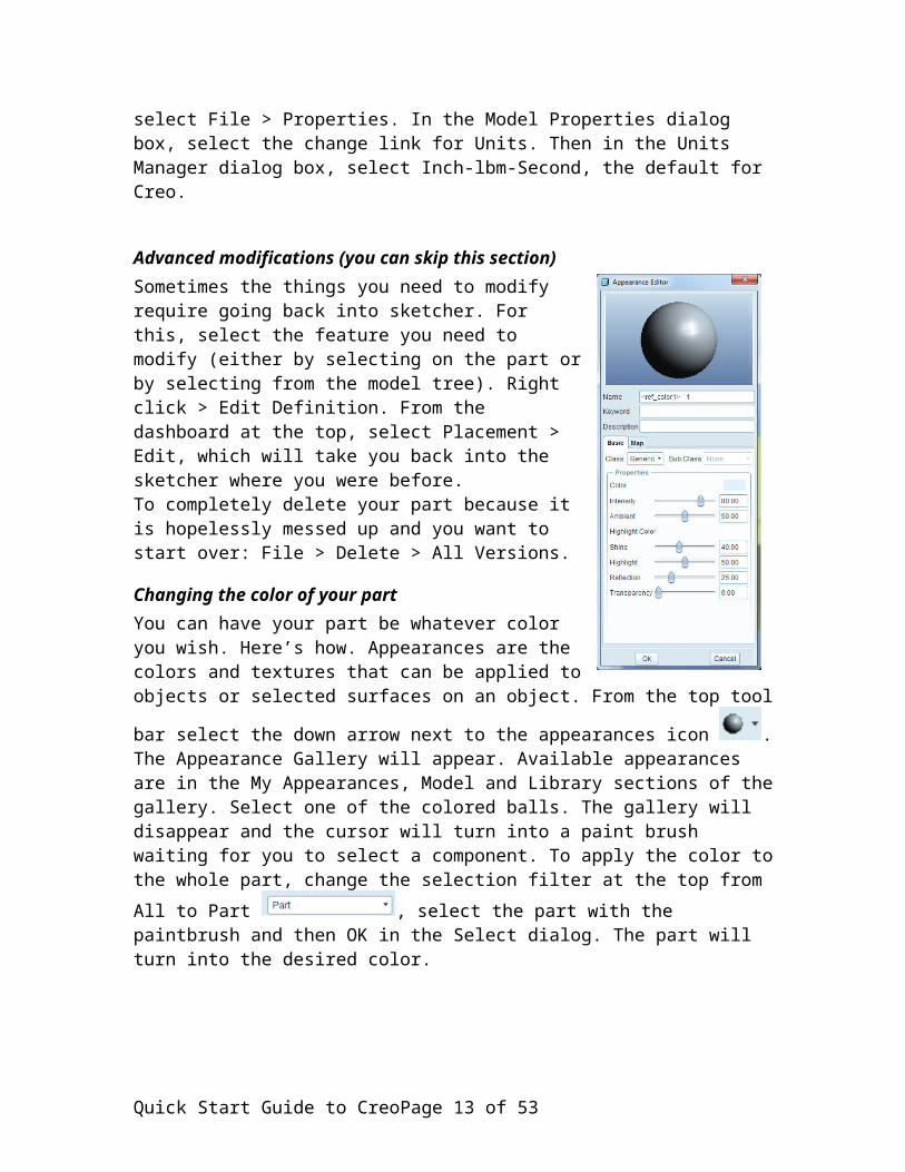
Advanced modifications (you can skip this section)Sometimes the things you need to modify require going back into sketcher. For this, select the feature you need to modify (either by selecting on the part or by selecting from the model tree). Right click > Edit Definition. From the dashboard at the top, select Placement > Edit, which will take you back into the sketcher where you were before. To completely delete your part because it is hopelessly messed up and you want to start over: File > Delete > All Versions.
Quick Start Guide to Creo Page 9 of 42

Changing the color of your partYou can have your part be whatever color you wish. Here’s how. Appearances are the colors and textures that can be applied to objects or selected surfaces on an object. From
the top tool bar select the down arrow next to the appearances icon . The Appearance Gallery will appear. Available appearances are in the My Appearances, Model and Library sections of the gallery. Select one of the colored balls. The gallery will disappear and the cursor will turn into a paint brush waiting for you to select a component. To apply the color to the whole part, change the
selection filter at the top from All to Part , select the part with the paintbrush and then OK in the Select dialog. The part will turn into the desired color.
To reset the appearances, in the Appearance Gallery select Clear Appearance, or in the drop down, Clear All Appearances.
To add a new appearance, in the Appearance Gallery select More Appearances. The Appearance Editor shown at right will appear. Type a name for your color in the name box. In the Properties area, click the color sample to the right of the word “Color.” The Color Editor will appear. Use the Color Wheel or the RGB Sliders to set the color you want. The new color will be in the My Appearances section of the Appearances Gallery.
Coloring is an art. Pick colors that are pleasing to the eye, but at the same time show off your part or assembly to its best advantage. Color may look different on printouts than the monitor. Often, brightening up the color with the Intensity slider helps. Experiment to find something you like. For school or professional assignments, do not turn in anything with marble or wood-grain coloring.
Tip: Sometimes you need to change the default light blue background color, for example if your printer insists on printing the background something other than white. To change the background, View > Display Settings > System Colors. Change Background to white and uncheck Blended Background.
Save your part!
Printing your partBefore printing a part, turn the display of datum planes, axes, datum points, coordinate systems and the spin center using the appropriate buttons on the top tool bar. To print a part, File > Print. To create a PDF, File > Save a Copy > Type = PDF. In the resulting dialog box, watch for the selection where you can choose landscape or portrait orientation.
Quick Start Guide to Creo Page 10 of 42

Adding a holeDrill a hole in the front face of the cube that goes all the way through. The hole should be 2.00 over from the left side, 2.00 up from the bottom and 0.75 in diameter. Here is how to do it.
Place the part in default orientation (Ctrl+D)
Change the Selection Filter at the top Geometry.
Pick the hole tool from the right tool bar .
The hole dashboard will open
Carefully select the front surface of the cube, clicking about where you want the center of the hole to be located. Be sure to select the front of the cube, not the top. To select carefully, hover the mouse until the proper surface is outlined in blue, then left-click where you want the hole. Sometimes it is hard to determining which the front surface is because your eye plays tricks on you. Switching between shaded, hidden line and wire-frame views can help. Do not select the FRONT datum plane, but instead the front surface of the hole. Another way to guarantee you are on the front is to orient the part in
FRONT view using the Saved view list button , and then click right on the front surface for placing the hole.
Are you on the front surface? If so, you will see something like this, which is Creo making a guess about where your hole is placed.
Quick Start Guide to Creo Page 11 of 42

Now you must add the details. Zoom in a bit so you can see what’s going on.
Find the three drag handles, which are the small white rectangles. Try moving the center of the hole, changing its depth, and changing its diameter by moving the handles.
The two green diamond location handles must be tied to two of the side surfaces of the cube part to precisely locate the hole with respect to its surfaces. Drag one handle down until the bottom surface lights up, then let go. Drag the other over until it is tied to the left surface. When setting these location handles, make sure they are tied to surfaces rather than to edges. One way of ensuring this is to select the Selection filter at the bottom right to Surface. The reason you always want to dimension to surfaces because edges can change if rounded or chamfered. Sometimes placing the references is easier if you orient the part to a front view. (From the top tool bar, Saved View list button > FRONT). Here is how it looks with the location handles set
Once the location handles are set, double click on the numbers. Set the diameter to 0.75, the distance from the bottom to 2.00, and the distance from the left to 2.00.
Change the hole type to Thru all using the Depth Spec button on the hole dashboard. The
thru all icon is the one that looks like the hole goes through everything . Click the check mark at the far right of the hole dashboard to complete the hole.
Spin, and zoom to admire your work.
Quick Start Guide to Creo Page 12 of 42
Is your hole in the wrong place? Select the hole on the model tree, then R-click and pick Edit from the pop up menu. Dimensions can be changed by double-clicking on the numbers. To change which surfaces the hole is referenced to, select the hole > R-click > Edit definition. This takes you back into the dashboard where you can change anything and everything about the hole including the reference handles or the drilling surface.
Save your work.
File > Close window to shut down the cubic part window. You can always bring it back with File > Open.
Creating the pinNow make the second part, a pin, which will look like this.
Like most parts with circular symmetry, it is made most easily using a revolve. A revolve takes a half cross-section drawn in the sketcher and sweeps it around a 360 deg. circle to form a solid. Here is how to make the pin.
File > New > Part > Name = “pin” > OK
The default datum planes will appear. If not, turn them on from the top toolbar.
Quick Start Guide to Creo Page 13 of 42

Select the Revolve tool from the right tool bar . You are telling Creo that you are going to sketch a cross section and then revolve that section about a centerline to create a solid part.
The revolve dashboard will appear
Select Placement, then Define, then the FRONT plane to tell Creo you are sketching the cross section on the front plane.
Click Sketch in the Sketch dialog box.
You are now in sketcher, ready to create the cross section of your part. To be accurate, you will be sketching one half of the cross section because what you sketch will be revolved about a center line to create the solid part.
Revolved sections require a center line. Click the down arrow on the Line tool and select the Geometry Centerline tool, the thicker of the two available centerline tools
Using the centerline tool, left click on the horizontal reference line once towards the left of the screen and once towards the right. Notice how the centerline snaps to the reference line and is coincident with the line defining the TOP datum plane.
Quick Start Guide to Creo Page 14 of 42
Finish centerline about here
Start centerline about here

Select the Line tool. Using the line tool, create four line segments that look something like this.
Next, create a tangent arc on the right side of the profile using the Arc tool . Click on the end of the open line you created in the last step. Then move the mouse down to the center line. When you get it right, the Intent Manager will snap the arc to the center line and it will be an exact quarter-circle. Click to finish the arc. The result will look something like this.
Quick Start Guide to Creo Page 15 of 42

Finally, select and use the line tool to close the bottom by drawing line segment along the center line from the left side to the end of the arc. It will look like this.
Note that the Intent Manager has inserted default dimensions in gray because it thinks these are the dimensions you want. You actually want a different set of dimensions and so must select the dimension tool to create the desired dimensions which are: (1) the diameter of the head, (2) the diameter of the shaft, (3) the thickness of the head, and (4) the overall length.
Tip: If the sketch has length constraints in white (e.g. two lines marked L1) that you do not want, select the constraint and delete.
Start by dimensioning the diameter of the head. Creating a diameter dimension with the dimension tool is a left click on the line that defines the outer diameter of the head, a left click on the centerline, a left click on the outer line, and finally a center click to place the dimension. Be sure to select lines rather than points because otherwise you may get unexpected results. When you have it right, the sketch will look like this.
Quick Start Guide to Creo Page 16 of 42

If the extension line of the dimension only goes to the center line it means you did not do the extra left click on the outer line of the pin before placing the dimension.
Use the same procedure to create the dimension that defines the diameter of the shaft. Left click on the outer diameter of the shaft, left click on the center line, left click on the outer diameter, center click to place the dimension.
Next create the dimension that defines the thickness of the head by left clicking on the vertical line that defines the left of the head, left clicking the vertical line that defines the right of the head, and center clicking to place the dimension. Again, click on lines rather than on corners.
Finally, create the dimension that defines the overall length of the pin. Left click on the vertical line at the far left, left click on the point that is at the end of the arc, center click to place.
The sketch should now look something like this.
Quick Start Guide to Creo Page 17 of 42

Now that the dimension set is complete, it is time to change the dimension values, using
the modify dimensions tool . Select the tool then click on all four dimension numbers, which will show up in the Modify Dimensions dialog box
Uncheck Regenerate, then change the dimension to their proper values: diameter of head = 1.00, diameter of shaft = 0.75, thickness of head = 0.50, overall lengh = 5.00. When
Quick Start Guide to Creo Page 18 of 42

done, click on the arrow in the dialog box and the part will regenerate with the correct
dimensions. Click the Refit button on the top tool bar and the part will fill the window.
You can also change a dimension by double clicking its number.
The sketch is complete. Exit the sketch by clicking the done arrow .
The pin is in yellow, but is not complete. In the revolve dashboard at the top, confirm that 360.00 is entered in the box that defines the angular sweep of the revolve.
When you are satisfied, click the done arrow at the right to exit the revolve dashboard.
The pin is complete. Turn off the display of datum planes, axes and coordinate systems
by clicking the appropriate display buttons along the top toolbar
Spin and admire your work. Ctrl+D returns the part to default view.
Try turning off the Spin Center in the top tool bar , then zooming with the scroll window and spinning the part around to examine the underside of the cap. For more complex parts, you need to become adept at manipulating the part for viewing.
Color your pin choosing a color that contrasts with the color you chose for the block. If you have to modify a dimension, right click the Revolve 1 feature in the menu tree at
the left and select Edit. Double click on any dimension to change. After making the change, use Ctrl+G to regenerate the part.
Save your part.
This completes the pin. Another way to make the pin would be to make a flat end and then to come in later with a round feature. Generally, you want to make your base part
Quick Start Guide to Creo Page 19 of 42

with as few line segments as possible, then add detail by adding features such as cuts and rounds. Limit your base feature to ten entities or less.
Creating the assemblyThe Creo assembly tools allow you to join parts into a final product. The process used is to bring the base part (the cubic for this tutorial) into the assembly and constrain (align) to the default datum planes. The next part (the pin) is then brought into the assembly. Next, you define two or three constraints that fix the position and orientation of the new part to the existing part. For the pin part, only two constraints are needed. For the first constraint you will align the surface of the shaft with the surface of the hole on the cubic. For the second constraint you will offset mate the front surface of the cubic to the underside of the head of the pin. The mate offset constraint lets you specify any distance you want between those two surfaces thus allowing the pin to set flat against the block (offset = 0) or to be an arbitrary distance away. Because the pin has circular symmetry, you don't care how it is rotated so a third constraint is not needed.
Step 1: Create the assembly fileFile > New > Assembly > [name the assembly "pin_cube" or anything convenient] > OK
A set of default datum assembly planes will appear.
Step 2: Bring the cubic part into the assembly
Select the Add Component tool on the right toolbar In the resulting dialog box, open the cubic part. The block will appear in the assembly window. Click to place the block anywhere on the window.
The Component Placement tools will be in the Dashboard area at the top.
Note that the STATUS is listed as No Constraints because the cube is not constrained to anything in the workspace.
The constraint type drop down menu is Automatic. Change to Default. Now the STATUS is Fully Constrained because the part has been constrained to the datum planes.
At the far right of the placement dashboard, click on the , which says you are done with the first part.
Step 3: Bring the pin into the assemblySelect the Add Component tool again and this time open the pin part from the dialog box. The pin will appear in the assembly window waiting to be constrained to the cube. Click to temporarily park the pin.
Quick Start Guide to Creo Page 20 of 42

If you don't like where the pin is located, because it has no constraints, it can be moved. From the dashboard, select Move then select Translate in the Motion Type drop-down. L-click in the assembly window and move the mouse to move the pin. L-click again to drop the pin. Note that this type of move is purely for the convenience of the user and has nothing to do with how the parts are constrained in the assembly.
After moving, click Move again to close the motion box.
Step 4: Constrain the pin to the blockThe pin will be constraint to the block with two constraints, Insert and Mate Offset.
Constraint #1: In the dashboard, select Insert from the constraint type drop down menu
Note that the message area just above the dashboard is telling you to select an aligning surface or axis on one part.
Hover the mouse over the pin until one half of the surface of the shaft is highlighted, then L-click to select. The surface will turn red with an Insert callout.
Quick Start Guide to Creo Page 21 of 42

Note that the message area is now telling you to select the alighting surface on the other part, which will be the inside surface of the hole. Inserting means the two surfaces are parallel but they don’t have to touch, which allows the pin to be smaller than the hole. The Align constraint has the same function as Insert for a pin in a hole.
Hover the mouse over the inside of the hole until one half of the surface is highlighted then L-click to select.
The pin is now brought into alignment with the hole.
]In fact, the pin may have moved right inside the block and perhaps you can't see it in shaded view. Switch to hidden line view to locate the pin. Or, like the above image, the pin may be flipped around.
Note that when you now try to move the pin using the Move tab, it will only move axially because of the insert constraint.
Click the Move tab and move the pin out of the hole. Turn off the datum planes for
clarity using the button on the top tool bar .
Constraint #2: Hover your mouse over the front surface of the cube until it highlights, then L-click to select. The surface will turn red and be tagged with Automatic. In the dashboard, change the constraint from Automatic to Mate.
Quick Start Guide to Creo Page 22 of 42

In the dashboard, in the drop-down offset type selection box to the right of the constraint type box, select Offset, which has the icon of surfaces separated with a dimension.
Tip: If you had wanted the pin head to always sit solidly on the cube surface, you would select Offset Type to be Coincident.
Note that the message area is telling you to select a mating surface on the other part. You are selecting the underside of the head of the pin.
To get to the surface you want, rotate the assembly and zoom in for a clear view, perhaps something like this.
Quick Start Guide to Creo Page 23 of 42

Now hover the mouse over the underside of the head until it highlights. The surface to select is the one highlighted in the image below. Choose carefully.
L-click to select the surface. The pin will immediately be flipped and in the hole, like this
Note that the dashboard now has STATUS: Fully Constrained, because the pin is not constrained to the cube and cannot be moved.
Select the Check at the far right of the dashboard to complete the assembly of the pin into the cube. Ctrl+D to bring the assembly into default view.
Now adjust the distance between the head of the pin and the cube. Select the pin either by directly double-clicking the pin or by R-clicking the pin in the menu tree and selecting Edit. The offset dimension should appear. In the image below, the offset is 1.399.
Quick Start Guide to Creo Page 24 of 42

Double-click on the offset (the 1.399) and change to 0.25. Hit Ctrl+G to regenerate the assembly. The result will be something like this.
Save your work.
Spin and zoom to admire your work.
You now are an expert at assembly. For most parts, you only need to use the Insert, Align and Mate offset constraints even though many other options are available. Parts without circular symmetry require three constraints. If you always think about design intent when you set constraints, your assemblies will be in good shape.
Quick Start Guide to Creo Page 25 of 42

Tip: If you have a complex assembly, create a sub-assembly and then do a final assembly of the sub-assemblies.
Detail DrawingsFabricating a part generally requires a fully-dimensions detail drawing with front, side and top views. A small outlined 3-D view is often included at the top right to aid in visualizing the part shape.
Here is how to make a detail drawing of the cube.
Create a new drawing. File > New > Drawing. Give it a convenient name, for example “cube” then hit OK.
The New Drawing dialog window will appear.
Quick Start Guide to Creo Page 26 of 42

In the New Drawing dialog, use the Browse button to find the cubic part and make it the default model. (Tip: Before starting the drawing, open the cubic part. It will then automatically appear as the default model when you start the drawing)
In the Specify Template area of the New Drawing dialog, select Use template.
In the Template area, use the Browse button to open the dialog with drawing template choices.
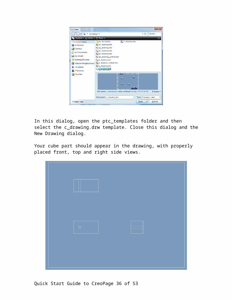
In this dialog, open the ptc_templates folder and then select the c_drawing.drw template. Close this dialog and the New Drawing dialog.
Your cube part should appear in the drawing, with properly placed front, top and right side views.
Quick Start Guide to Creo Page 27 of 42

If the format is not the same as above, delete the drawing and try to locate the correct template, which may be in different folders for different computer systems. Do not use the c_drawing template that has border features and a title block.
If showing, turn off datum plans and coordinate systems using .
At the bottom left of the drawing, find the SCALE 0.500 mark , which indicates that the work is being
shown in a 0.5:1 scale.
Double click on the 0.500 and change to 1.00. This will enlarge the views. Generally, you want your parts to fill the paper while still leaving room for dimensions and comments.
Hint: If the part appears much smaller than you expect, it may be because the units are set to mm rather than inches. To change, open the part and then File > Properties > Units.
Often, the default positioning of the views needs some tweaking. Right-press in the drawing window (hold the right mouse button down for a while) until the popup appears. Uncheck Lock View Movement. Click on a view to move. Note that Creo constrains the motion to maintain alignment between views.
Move the views to approximately match the figure below.
Quick Start Guide to Creo Page 28 of 42

Relock the views.
Add a 3-D view of the cube to the upper right corner. Right-press in the drawing window and select Insert General View from the pop-up.
On the drawing, left click in the top right quadrant where you want the 3-D view to be located. The 3-D view will appear along with the Drawing View dialog box.
Quick Start Guide to Creo Page 29 of 42

In the Drawing View dialog box select Scale > Custom Scale and enter 0.5, then Apply and see what happens.
In the Drawing View dialog box, select View Display, then under Display style select No Hidden. Select Apply to view, then Close to close the Drawing View dialog. The drawing will now look something like this.
Quick Start Guide to Creo Page 30 of 42

Admire, then save your drawing.
Now that the views are placed, you can add the dimensions. In the top ribbon bar, select the Annotate tab
Select the Show Model Annotations button . (Or, in the drawing window, right-press and select Show Model Annotations from the pop-up.) The Show Model Annotations dialog appears.
Quick Start Guide to Creo Page 31 of 42

In the Model Tree (lower left of the screen), click on the part name (CUBIC.PRT). All of the part dimensions will appear in the Show Model Annotations dialog and in red on the drawing. Mouse over the check boxes in the Show Model Annotations dialog and notice how the corresponding dimensions in the drawing turn cyan. You could individually
check dimensions. For this part it is easier to use the select all button , then click Apply.
In the Show Model Annotations dialog, select the datum axis tab . Axis centerline options will appear. Select the check boxes so that centerlines appear for the three projected views but not in the 3-D view. Click OK to close the Show Model Annotations dialog. Your drawing will look something like this
Quick Start Guide to Creo Page 32 of 42

The dimensions and center lines for the holes appear on the drawing with Creo’s best guess as to view and location.
Tip: For a complex part with dozens or hundreds of dimensions, do not use the Select All button because the drawing will quickly be overwhelmed by dimensions. Instead select the minimal set of needed dimensions.
As the designer you can change dimension values in drawing mode and any changes will ripple through the relevant parts and assemblies because they are all stored in the same database. For example, Select Edit > Value, then click on the value that defines the hole diameter. Change to 2.0. Regenerate the part (Ctrl+G). Open the cubic part (File > Open) and confirm that the part has indeed changed. Change the hole back to 0.75. Regenerate.
Clean up dimensionsWhile the dimensions are displayed, they will not be in the best locations or attached to the best views to clearly communicate your design intent.
Select the Annotate tab on the top ribbon bar so that dimensions highlight when you mouse over. Now you can adjust dimension placement.
Quick Start Guide to Creo Page 33 of 42

Select a dimension with an L-click on its number part. Then L-press and drag to move the dimension. Don’t worry if the extension lines touch the part; Creo will clean this up at printout time.
Sometimes you need to move the dimension to a different view. L-click the dimension to select (turns red). R-press until the pop-up menu appears. Select Move Item to View. L-click the view where you want the dimension to go.
If you like your arrows on the outside, select the dimension, R-press until the pop up menu appears and select Flip Arrows. For diameter dimensions, it is generally preferable to have the arrow on the outside.
To clean the drawing, use the Repaint button on the top tool bar , or Ctrl-R.
Work on your drawing to get the dimensions placed as they are in this figure.
Save your work.
Hint: You can get Creo to clean up the dimensions if things are looking a little crowded.
Use the Cleanup Dimensions button in the Annotate ribbon, or R-
Quick Start Guide to Creo Page 34 of 42

press in the drawing window and select Cleanup Dimensions. Press the left button and drag the mouse to define a selection box around the entire drawing. Click OK on the Select box. Click Apply, then Close the Clean Dimensions box. The gray lines that appear are Snap Lines that dimensions are snapped to when cleaned. They won’t appear on printouts. If you don’t like them now, select and delete. Repaint (or CTRL+R) to repaint the screen so you can see the changes. For a complex drawing, use the auto cleanup to get things somewhat in shape, then go back and fine tune so the dimensions are just where you want them.
To erase any dimension or centerline, select so it turns red, right-press and chose Erase from the pop-up menu
Add a title blockDrawings need a title, name and date. At some point you should learn how to use a drawing template that adds a standard title block. For this tutorial, you create text items using a text note and enclose in a pseudo title block by drawing a rectangle using the line tool
To add a text note, in the Insert section of the Annotate ribbon choose Insert Note . On the NOTE TYPES menu that appears on the right, select No Leader, Enter, Horizontal, Standard, and Default (these should all be highlighted.) L-click on Make Note. Next, L-click on the drawing where the note should go, in this case the lower right. Enter the desired text in the pop-up text box that appears at the bottom of the drawing area. Lettering should be in all capitals. Pressing Enter will take you to the next line. The first line should have the title of the drawing (CUBIC), the second line your name, and the third line the date. Press Enter twice (or the check mark to the right of the entry box) to close the note, then Done/Return on the NOTE TYPES menu.
Tip: The Text Symbol box that appears when you make a note lets you enter a variety of symbols useful for CAD drawings, for example the symbol for a counter bore and the symbol for hole depth.
To move the note: L-click the note to select, then L-press to drag to a new location.
Double click the note to edit (or select, then right-press and select Properties from the popup menu.) In the Note Properties box, the Text Style tab lets you change the font or text size. Use the Preview button to see your changes.
Draw a rectangle around your text using the 2-point line tool located in the Insert area of
the Sketch ribbon . L-click to start the line and L-click again to finish. Before the second L-click, right-press and select angle. Enter 0 to constrain the line to be horizontal. Center-click to clear the line tool. If you don’t like the line, select until it turns red, R-press and select Delete from the pop-up menu.
Quick Start Guide to Creo Page 35 of 42
Tip: While working on the drawing, use the scroll wheel to zoom in and Shift + Middle-
Button to pan. To bring back the default view, use the Refit button at the top.
Save, then admire your drawing. It should be close to this one.
Print your drawingPrinting instructions will vary depending on what computer you are using. While the drawing is C size, it will be printed on standard on A size (8.5 by 11 inch) paper so the drawing must be scaled to fit.
To print, File Print. In the Printer Configuration dialog, click the Page tab and change Size from C to A.
Quick Start Guide to Creo Page 36 of 42

Click OK then print to a PDF print driver to make a PDF file for storing and electronic transmission. Or print to a regular printer to make a hard copy.
Another way of printing is File > Save a Copy… In the Save a Copy dialog box, select PDF for the Type. Then, in the Color area of the PDF Export Settings dialog box, select Monochrome.
Hint: You may or may not get an outer frame on the printout. The frame is not an actual frame but rather represents the edge of the drawing sheet.
Detail drawing of the pinThe pin as circular symmetry and only needs a front and right side view. There are several ways to place the pin dimensions. The appendix to this document shows one example. If the 360 deg. dimension from the revolve shows up, select and erase.
All doneCongratulations. You have completed the tutorial and are now licensed to add “Creo (Pro/ENGINEER)” to your resume. If this tutorial is part of a course assignment, review the assignment instructions to determine what to turn in.
Other things you can doRender a part you are designing or render a product you own, using dial or digital calipers to find the dimensions.
In File > Save a Copy, one of the Type options is PDF U3D, an interactive 3D PDF spec. Try saving in this format and viewing the file in Acrobat where you can zoom and spin
Quick Start Guide to Creo Page 37 of 42

the part. This is a convenient way to send the model for viewing by someone who does not have Creo.
Another File > Save a Copy option is saving as a Zip file. If you do this for an assembly, the zip file will include all of the parts files. This is handy when emailing a project to a colleague who does have Creo.
Fun Tip: If you like fun, but completely useless features, try this. Get a part up on the
screen. Turn on the Orient Mode button at the top. Right click in the main graphics area and select Velocity from the pop up menu. Press on the part with the center button. The further away you drag the mouse while pressing, the faster the object will spin. This will really impress your friends!
The Creo startup screen has links to online tutorials you can run.
Quick Start Guide to Creo Page 38 of 42

APPENDIX 1Exhibits for UMN ME 2011 assignment.
Exhibit A: Pin-cube assembly.
Quick Start Guide to Creo Page 39 of 42

Exhibit B: Cube drawing.
Quick Start Guide to Creo Page 40 of 42

Exhibit C: Pin drawing.
Quick Start Guide to Creo Page 41 of 42

APPENDIXTrouble shooting
Problem:When hovering over a feature, it does not turn blue (no prehighlighting) or graphics are running slow.
Solution:Update to the latest graphics and video driver for your computer display hardware.
Quick Start Guide to Creo Page 42 of 42