Embed Size (px)
Citation preview

V4.0
COMMUTATEURS L2+ GIGABIT GÉRÉS
MANAGED L2+ GIGABIT SWITCHESMANAGED L2+ GIGABIT SWITCHES
Quick Start Guide Quick-Start Anleitung
Guide de Démarrage Rapide
S3900-24F4S
1 2 3 4 5 6 7 8 9 10 11 12 13 14 15 16 17 18 19 20 21 22 23 24 21 22 23 24
2526
2728
SYS
PWR
CONSOLEMGT
S3900-24T4S
1 2 3 4 5 6 7 8 9 10 11 12
13 14 15 16 17 18 19 20 21 22 23 24
25
25
26
26
2728
27
28
SYS
PWRRESETCONSOLE
MGT

1
EN
Introduction
Thank you for choosing S3900 Series Stackable Managed Switches. This guide is designed to
familiarize you with the layout of the switch and describes how to deploy the switch in your network.
Accessories
Grounding Cable x1
Power Cord x2 Mounting Bracket x2
M4 Screw x6Rubber Pad x4
Console Cable x1
NOTE: S3900 series switches have dust plugs delivered with them. Keep the dust plugs properly and use them to protect idle optical ports.
S3900-24F4S
S3900-48T4S
S3900-24T4S
S3900-24F4S1 2 3 4 5 6 7 8 9 10 11 12 13 14 15 16 17 18 19 20 21 22 23 24 21 22 23 24
25 26 27 28
SYS
PWR
CONSOLEMGT
S3900-24T4S
1 2 3 4 5 6 7 8 9 10 11 12 13 14 15 16 17 18 19 20 21 22 23 24
25
25
26
26
27 28
27
28
SYS
PWRRESET
CONSOLE
MGT
S390
0-48
T4S
1 2 3 4 5 6 7 8 9 10 11 12 13 14 15 16 17 18 19 20 21 22 23 24 25 26 27 28 29 30 31 32 33 34 35 36 37 38 39 40 41 42 43 44 45 46 47 48CONSOLEMGT
SYS
PWR
49 50 51 52

2
EN
Hardware Overview
Front Panel Ports
S3900-24T4S
1 2 3 4 5 6 7 8 9 10 11 12 13 14 15 16 17 18 19 20 21 22 23 24
25
25
26
26
27 28
27
28
SYS
PWRRESET
CONSOLE
MGT
RJ45 SFP+
MGT
Console
Ports Description
RJ45
SFP+
SFP
MGT
Console
10/100/1000BASE-T ports for Ethernet connection
SFP ports for 1G connection
SFP+ ports for 1/10G connection
An out-of-band Ethernet management port
An RJ45 console port for serial management
S3900-24T4S
S3900-24F4S1 2 3 4 5 6 7 8 9 10 11 12 13 14 15 16 17 18 19 20 21 22 23 24 21 22 23 24
25 26 27 28
SYS
PWR
CONSOLEMGT
SFP SFP+
MGT Console
S390
0-48
T4S
1 2 3 4 5 6 7 8 9 10 11 12 13 14 15 16 17 18 19 20 21 22 23 24 25 26 27 28 29 30 31 32 33 34 35 36 37 38 39 40 41 42 43 44 45 46 47 48CONSOLEMGT
SYS
PWR
49 50 51 52
RJ45 SFP+
MGT Console
S3900-24F4S
S3900-48T4S

3
EN
Front Panel Button
S3900-24T4S
1 2 3 4 5 6 7 8 9 10 11 12 13 14 15 16 17 18 19 20 21 22 23 24
25
25
26
26
27 28
27
28
SYS
PWRRESET
CONSOLE
MGT
RESET
Button Description
RESET
Restart: Press and release the Reset button quickly.
Restore to Factory Default Settings: Press and hold the Resetbutton for more than ten seconds.
Back Panels
S3900-24T4S
S3900-24T4S/S3900-48T4S
S3900-24F4S
90-264VAC 47-63Hz90-264VAC 47-63Hz
Dual Power Supplies
Dual Fans Grounding Point
Grounding Point
Dual Power Supplies
90-264VAC 47-63Hz90-264VAC 47-63Hz
4
EN
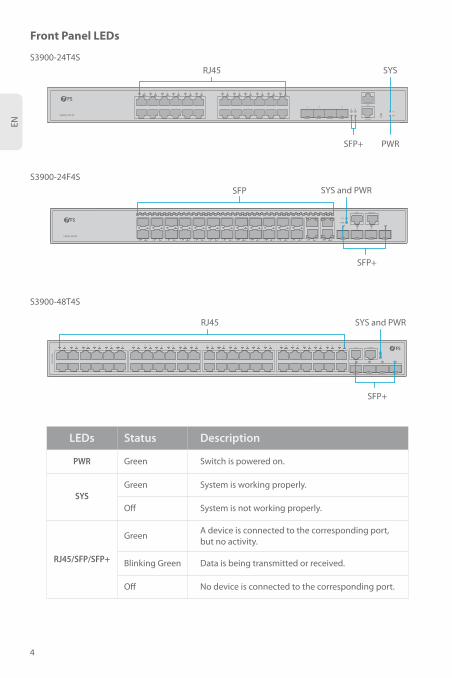
Front Panel LEDs
S3900-24T4S
1 2 3 4 5 6 7 8 9 10 11 12 13 14 15 16 17 18 19 20 21 22 23 24
25
25
26
26
27 28
27
28
SYS
PWRRESET
CONSOLE
MGT
SYS
PWR
RJ45
SFP+
LEDs DescriptionStatus
PWR
SYS
RJ45/SFP/SFP+
Green
Green
Green
Blinking Green
System is working properly.
System is not working properly.Off
Off
Switch is powered on.
Data is being transmitted or received.
No device is connected to the corresponding port.
A device is connected to the corresponding port, but no activity.
S3900-24T4S
S3900-24F4S
S3900-48T4S
S3900-24F4S1 2 3 4 5 6 7 8 9 10 11 12 13 14 15 16 17 18 19 20 21 22 23 24 21 22 23 24
25 26 27 28
SYS
PWR
CONSOLEMGT
SFP
SFP+
SYS and PWR
S390
0-48
T4S
1 2 3 4 5 6 7 8 9 10 11 12 13 14 15 16 17 18 19 20 21 22 23 24 25 26 27 28 29 30 31 32 33 34 35 36 37 38 39 40 41 42 43 44 45 46 47 48CONSOLEMGT
SYS
PWR
49 50 51 52
SYS and PWRRJ45
SFP+

5
EN
The installation site must be well ventilated. Ensure that there is adequate air flow around the
switch.
Before you begin the installation, make sure that you have the following:
Site Environment:
Do not operate it in an area that exceeds an ambient temperature of 40°C.
Installation Requirements
Phillips screwdriver.
Standard-sized, 19" wide rack with a minimum of 1U height available.
Category 5e or higher RJ-45 Ethernet cables for connecting network devices.
The installation site must be free from leaking or dripping water, heavy dew, and humidity.
Ensure rack and working platforms are well earthed.
Be sure that the switch is level and stable to avoid any hazardous conditions.
Do not install the equipment in a dusty environment.

6
EN
Rack Mounting
1. Secure the mounting brackets to the two sides of the switch with six M4 screws.
25
25
26
26
2728
27
28
SYS
PWRRESETCONSOLE
MGT
Desk Mounting
1. Attach four rubber pads to the bottom.
2. Place the chassis on a desk.
Mounting the Switch

7
EN
2. Attach the switch to the rack using four M6 screws and cage nuts.
1. Connect one end of the grounding cable to a proper earth ground, such as the rack in which the
switch is mounted.
2. Secure the grounding lug to the grounding point on the switch back panel with the washers and
screws.
Grounding the Switch
90-264VAC 47-63Hz
CAUTION: The earth connection must not be removed unless all supply connections havebeen disconnected.

8
EN
Connecting the RJ45 Ports
1. Connect an Ethernet cable to the RJ45 port of a computer, printer, network storage, or other network
devices.
2. Connect the other end of the Ethernet cable to the RJ45 port of the switch.
1. Plug the AC power cord into the power port on the back of the switch.
2. Connect the other end of the power cord to an AC power source.
Connecting the Power
90-264VAC 47-63Hz
WARNING: Do not install power cable while the power is on.
S3900-24T4S
1 2 3 4 5 6 7 8 9 10 11 12
13 14

9
EN
Connecting the SFP+ Ports
1. Plug the compatible SFP+/SFP transceiver into the SFP+ port.
2. Connect a fiber optic cable to the fiber transceiver. Then connect the other end of the cable to
another fiber device.
Connecting the Console Port
1. Insert the RJ45 connector into the RJ45 console port on the front of the switch.
2. Connect the DB9 female connector of the console cable to RS-232 serial port on the computer.
18 19 20 21 22 23 24
25
25
26
26
27
27
28
CONSOLE
MGT
SYS
PWRRESET
28
Connecting the Management Ports
WARNING: Laser beams will cause eye damage. Do not look into bores of optical modules or optical fibers without eye protection.

10
EN
Connecting the MGT Port
1. Connect one end of a standard RJ45 Ethernet cable to a computer.
2. Connect the other end of the cable to the MGT port on the front of the switch.
17 18 19 20 21 22 23 24
25
25
26
26
2728
27
28
SYS
PWRRESETCONSOLE
MGT
Stacking the S3900 Series Switches
The S3900 series switches support stacking up to 6 switches between the same models together.
Switches in the series can be physically stacked using optical fiber cables connected to SFP+ transceivers,
or 10G Direct Attach Cables (DAC). Only the last two SFP+ ports on the switch can be used for physical
stacking.
S3900-24T4S
1 2 3 4 5 6 7 8 9 10 11 12 13 14 15 16 17 18 19 20 21 22 23 24
25
25
26
26
27 28
27
28
SYS
PWRRESET
CONSOLE
MGT
S3900-24T4S
1 2 3 4 5 6 7 8 9 10 11 12 13 14 15 16 17 18 19 20 21 22 23 24
25
25
26
26
27 28
27
28
SYS
PWRRESET
CONSOLE
MGT
S3900-24T4S
1 2 3 4 5 6 7 8 9 10 11 12 13 14 15 16 17 18 19 20 21 22 23 24
25
25
26
26
27 28
27
28
SYS
PWRRESET
CONSOLE
MGT

11
EN
Configuring the Switch Using the Web-based Interface
Configuring the Switch
Welcome to FS Ethernet Switch
English
Sign in
admin
******
Step 1: Connect your computer to the Management port or any Ethernet port of the switch using the
network cable.
Step 2: Set the IP address of the computer to 192.168.1.x.(“x” is any number from 2 to 254.)
? x
OK Cancel
General
I P a d d r e s s :
S u b n e t m a s k :
D e f a u l t g a t e w a y :
Y o u c a n g e t I P s e t t i n g s a s s i g n e d a u t o m a t i c a l l y i f y o u r n e t w o r ks u p p o r t s t h i s c a p a b i l i t y . O t h e r w i s e , y o u n e e d t o a s k y o u r n e t w o r ka d m i n i s t r a t o r f o r t h e a p p r o p r i a t e I P s e t t i n g s .
Internet Protocol Vers ion 4 (TCP/ IPv4) Propert ies
Use the fol lowing IP address :
Obtain an IP address automatical ly
Preferred DNS server:
Alternate DNS server:
Validate settings upon exit A d v a n c e d . . .
. . . 21168192
0255255255
. . .
. . .
. . .
. . .
Obtain DNS ser ver address automatical ly
Use the fol lowing DNS ser ver addresses :
Step 3: Open a browser, type http://192.168.1.1, and enter the default username and password,
admin/admin.
Step 4: Click Sign in to display the web-based configuration page.

12
EN
1. After configuring the stacking, the last two 10G ports will disappear from the configuration file,
which is normal. This design is to prevent misoperation.
2. If using the DAC as the stacking cable, the 1-3m DAC is recommended.
Stacking Configuration Troubleshooting
Configuring the Switch Using the Console Port
Troubleshooting
In the case of compatible cables and transceivers, the port cannot be up, please try to modify the port
mode to adapt or force the port speed to 1G/10G.
10G Port is not Working
Step 1: Connect a computer to the switch's console port using the supplied console cable.
Step 2: Start the terminal simulation software such as HyperTerminal on the computer.
Step 3: Set the parameters of the HyperTerminal: 115200 bits per second, 8 data bits, no parity, 1 stop
bit and no flow control.
Step 4: Enter the default username and password, admin/admin.
xQuick Connect
Protocol: Serial
Flow Control
DTR/DSR
RTS/CTS
XON/XOFF
Save sessionShow quick connect on startup
Open in a tab
Connect Cancel
COM3
115200
8
None
1
Port:
Baud rate:
Data bits:
Parity:
Stop bits:
Name of pipe:

13
EN
FS ensures our customers that any damage or faulty items due to our workmanship, we will offer a
free return within 30 Days from the day you receive your goods. This excludes any custom made
items or tailored solutions.
Support and Other Resources
Download
Help Center
Contact Us
https://www.fs.com/products_support.html
https://www.fs.com/service/fs_support.html
https://www.fs.com/contact_us.html
1. Test network connectivity through ping.
2. If the network is reachable, try restarting the switch.
3. Check if the corresponding service is enabled.
Connecting the Switch Remotely Unsuccessfully
The Port is not Working, the LED Indicator is Off
1. Ensure the switch ports are in the no shutdown state.
2. Check if the switch can read the DDM information.
3. Check if the port speed setting is correct.
4. Try looping the switch cable.
Product Warranty
Warranty: S3900 Series Switches enjoy 4 years limited warranty against defect in materials
or workmanship. For more details about warranty, please check at https://www.fs.com/poli-
cies/warranty.html
Return: If you want to return item(s), information on how to return can be found at
https://www.fs.com/policies/day_return_policy.html
4

14
DE
EinführungVielen Dank, dass Sie sich für einen Stackable-Managed-Switch der S3900-Serie entschieden haben.
Diese Anleitung soll Sie mit dem Layout des Switches vertraut machen und beschreibt, wie Sie den
Switch in Ihrem Netzwerk einsetzen.
Zubehör
Erdungskabel x1
Netzkabel x2 Montagehalterung x2
M4-Schraube x6 Gummipad x4
Konsolenkabel x1
HINWEIS: Die Switches der S3900-Serie werden mit Staubschutzkappen geliefert. Bewahren Sie die Kappen ordnungsgemäß auf und verwenden Sie sie, um ungenutzte optische Anschlüsse zu schützen.
S3900-24F4S
S3900-48T4S
S3900-24T4S
S3900-24F4S1 2 3 4 5 6 7 8 9 10 11 12 13 14 15 16 17 18 19 20 21 22 23 24 21 22 23 24
25 26 27 28
SYS
PWR
CONSOLEMGT
S3900-24T4S
1 2 3 4 5 6 7 8 9 10 11 12 13 14 15 16 17 18 19 20 21 22 23 24
25
25
26
26
27 28
27
28
SYS
PWRRESET
CONSOLE
MGT
S390
0-48
T4S
1 2 3 4 5 6 7 8 9 10 11 12 13 14 15 16 17 18 19 20 21 22 23 24 25 26 27 28 29 30 31 32 33 34 35 36 37 38 39 40 41 42 43 44 45 46 47 48CONSOLEMGT
SYS
PWR
49 50 51 52

15
DE
Hardware-Übersicht
Anschlüsse an der Vorderseite
S3900-24T4S
1 2 3 4 5 6 7 8 9 10 11 12 13 14 15 16 17 18 19 20 21 22 23 24
25
25
26
26
27 28
27
28
SYS
PWRRESET
CONSOLE
MGT
RJ45 SFP+
MGT
Konsole
Ports Beschreibung
RJ45
SFP+
SFP
MGT
Console
10/100/1000BASE-T-Ports für Ethernet-Anschluss
SFP-Ports für 1G-Verbindung
SFP+-Ports für 1/10G-Verbindung
Ein Out-of-Band-Ethernet-Management-Anschluss
Ein RJ45-Konsolenanschluss für die serielle Verwaltung
S3900-24T4S
S3900-24F4S1 2 3 4 5 6 7 8 9 10 11 12 13 14 15 16 17 18 19 20 21 22 23 24 21 22 23 24
25 26 27 28
SYS
PWR
CONSOLEMGT
SFP SFP+
MGT Konsole
S390
0-48
T4S
1 2 3 4 5 6 7 8 9 10 11 12 13 14 15 16 17 18 19 20 21 22 23 24 25 26 27 28 29 30 31 32 33 34 35 36 37 38 39 40 41 42 43 44 45 46 47 48CONSOLEMGT
SYS
PWR
49 50 51 52
RJ45 SFP+
MGT Konsole
S3900-24F4S
S3900-48T4S
16
DE
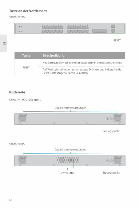
Taste an der Vorderseite
S3900-24T4S
1 2 3 4 5 6 7 8 9 10 11 12 13 14 15 16 17 18 19 20 21 22 23 24
25
25
26
26
27 28
27
28
SYS
PWRRESET
CONSOLE
MGT
RESET
Taste Beschreibung
RESET
Neustart: Drücken Sie die Reset-Taste schnell und lassen Sie sie los.
Auf Werkseinstellungen zurücksetzen: Drücken und halten Sie die Reset-Taste länger als zehn Sekunden.
Rückseite
S3900-24T4S
S3900-24T4S/S3900-48T4S
S3900-24F4S
90-264VAC 47-63Hz90-264VAC 47-63Hz
Duale Stromversorgungen
Zwei Lüfter Erdungspunkt
Erdungspunkt
Duale Stromversorgungen
90-264VAC 47-63Hz90-264VAC 47-63Hz
17
DE
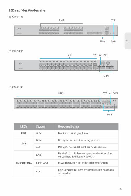
LEDs auf der Vorderseite
S3900-24T4S
1 2 3 4 5 6 7 8 9 10 11 12 13 14 15 16 17 18 19 20 21 22 23 24
25
25
26
26
27 28
27
28
SYS
PWRRESET
CONSOLE
MGT
SYS
PWR
RJ45
SFP+
LEDs BeschreibungStatus
PWR
SYS
RJ45/SFP/SFP+
Grün
Grün
Grün
Blinkt Grün
Das System arbeitet ordnungsgemäß.
Das System arbeitet nicht ordnungsgemäß.Aus
Aus
Der Switch ist eingeschaltet.
Es werden Daten gesendet oder empfangen.
Kein Gerät ist mit dem entsprechenden Anschluss verbunden.
Ein Gerät ist mit dem entsprechenden Anschluss verbunden, aber keine Aktivität.
S3900-24T4S
S3900-24F4S
S3900-48T4S
S3900-24F4S1 2 3 4 5 6 7 8 9 10 11 12 13 14 15 16 17 18 19 20 21 22 23 24 21 22 23 24
25 26 27 28
SYS
PWR
CONSOLEMGT
SFP
SFP+
SYS und PWR
S390
0-48
T4S
1 2 3 4 5 6 7 8 9 10 11 12 13 14 15 16 17 18 19 20 21 22 23 24 25 26 27 28 29 30 31 32 33 34 35 36 37 38 39 40 41 42 43 44 45 46 47 48CONSOLEMGT
SYS
PWR
49 50 51 52
SYS und PWRRJ45
SFP+

18
DE
Der Aufstellungsort muss gut belüftet sein. Sorgen Sie für eine ausreichende Luftzirkulation
um den Switch.
Bevor Sie mit der Installation beginnen, stellen Sie sicher, dass Sie Folgendes zur Verfügung haben:
Standortbedingungen:
Betreiben Sie das Gerät nicht in einem Bereich, der eine Umgebungstemperatur von 40°C
überschreitet.
Installationsanforderungen
Kreuzschlitzschraubendreher.
19"-Rack in Standardgröße mit einer Mindesthöhe von 1 HE.
RJ-45-Ethernet-Kabel der Kategorie 5e oder höher für den Anschluss von Netzwerkgeräten.
Der Installationsort muss frei von austretendem oder tropfendem Wasser, starkem Tau und
Feuchtigkeit sein.
Stellen Sie sicher, dass Gestell und Arbeitsplattform gut geerdet sind.
Stellen Sie sicher, dass der Switch eben und stabil steht, um Gefahrensituationen zu vermeiden.
Stellen Sie das Gerät nicht in einer staubigen Umgebung auf.

19
DE
Montage in einem Rack
1. Befestigen Sie die Montagehalterungen mit acht M4-Schrauben an beiden Seiten des Switches.
25
25
26
26
2728
27
28
SYS
PWRRESETCONSOLE
MGT
Bodenmontage
1. Bringen Sie vier Gummipads an der Unterseite an.
2. Stellen Sie das Gehäuse auf den Tisch.
Montage des Switch

20
DE
2. Befestigen Sie den Switch mit vier M6-Schrauben und Käfigmuttern am Rack.
1. Schließen Sie ein Ende des Erdungskabels an eine geeignete Erdung an, z. B. an das Rack, in dem
der Switch montiert ist.
2. Befestigen Sie die Erdungslasche mit den Unterlegscheiben und Schrauben am Erdungspunkt an
der Rückwand des Switches.
Erdung des Switch
90-264VAC 47-63Hz
ACHTUNG: Der Erdungsanschluss darf erst dann entfernt werden, wenn alle Netzanschlüsse abgezogen sind.
100-240V~, 50/60Hz, 0.8A

21
DE
Anschließen der RJ45-Ports
1. Schließen Sie ein Ethernet-Kabel an den RJ45-Anschluss eines Computers, Druckers,
Netzwerkspeichers oder anderer Netzwerkgeräte an.
2. Schließen Sie das andere Ende des Ethernet-Kabels an den RJ45-Port des Switches an.
1. Stecken Sie das Netzkabel in den Netzanschluss auf der Rückseite des Switches.
2. Schließen Sie das andere Ende des Netzkabels an eine Netzstromquelle an.
Anschließen der Stromversorgung
90-264VAC 47-63Hz
ACHTUNG: Installieren Sie das Netzkabel nicht, während das Gerät eingeschaltet ist.
S3900-24T4S
1 2 3 4 5 6 7 8 9 10 11 12
13 14

22
DE
Anschließen der SFP+-Ports
1. Stecken Sie den kompatiblen SFP+/SFP-Transceiver in den SFP+-Port.
2. Schließen Sie ein Glasfaserkabel an den Glasfaser-Transceiver an. Schließen Sie dann das andere
Ende des Kabels an ein anderes Glasfasergerät an.
Anschließen des Konsolen-Ports
1. Stecken Sie den RJ45-Stecker in den RJ45-Konsolenanschluss an der Vorderseite des Switches.
2. Verbinden Sie die DB9-Buchse des Konsolenkabels mit dem seriellen RS-232-Anschluss des
Computers.
18 19 20 21 22 23 24
25
25
26
26
27
27
28
CONSOLE
MGT
SYS
PWRRESET
28
Anschließen der Management-Ports
WARNUNG: Laserstrahlen können Augenschäden verursachen. Schauen Sie nicht ohne Augenschutz in Bohrungen von optischen Modulen oder Lichtwellenleitern.

23
DE
Anschließen des MGT-Ports
1. Schließen Sie ein Ende eines standardmäßigen RJ45-Ethernet-Kabels an einen Computer an.
2. Schließen Sie das andere Ende des Kabels an den MGT-Port an der Vorderseite des Switches an.
17 18 19 20 21 22 23 24
25
25
26
26
2728
27
28
SYS
PWRRESETCONSOLE
MGT
Stacking der Switches der Serie S3900
Die Switches der S3900-Serie unterstützen das Stacking von bis zu 6 Switches der gleichen Modelle
untereinander. Die Switches der Serie können mithilfe von Glasfaserkabeln, die mit
SFP+-Transceivern verbunden sind, oder 10G Direct Attach Cables (DAC) physisch gestapelt werden.
Nur die letzten beiden SFP+-Ports des Switches können für das physische Stacking verwendet werden.
S3900-24T4S
1 2 3 4 5 6 7 8 9 10 11 12 13 14 15 16 17 18 19 20 21 22 23 24
25
25
26
26
27 28
27
28
SYS
PWRRESET
CONSOLE
MGT
S3900-24T4S
1 2 3 4 5 6 7 8 9 10 11 12 13 14 15 16 17 18 19 20 21 22 23 24
25
25
26
26
27 28
27
28
SYS
PWRRESET
CONSOLE
MGT
S3900-24T4S
1 2 3 4 5 6 7 8 9 10 11 12 13 14 15 16 17 18 19 20 21 22 23 24
25
25
26
26
27 28
27
28
SYS
PWRRESET
CONSOLE
MGT

24
DE
Konfigurieren des Switches über die webbasierte Oberfläche
Konfigurieren des Switch
Welcome to FS Ethernet Switch
English
Sign in
admin
******
Schritt 1: Schließen Sie Ihren Computer über ein Netzwerkkabel an den Management-Port oder einen
beliebigen Ethernet-Port des Switches an.
Schritt 2: Setzen Sie die IP-Adresse des Computers auf 192.168.1.x ("x" ist eine beliebige Zahl von 2 bis
254.). Setzen Sie die Subnetzmaske des Computers auf 255.255.255.0
? x
OK Cancel
General
I P a d d r e s s :
S u b n e t m a s k :
D e f a u l t g a t e w a y :
Y o u c a n g e t I P s e t t i n g s a s s i g n e d a u t o m a t i c a l l y i f y o u r n e t w o r ks u p p o r t s t h i s c a p a b i l i t y . O t h e r w i s e , y o u n e e d t o a s k y o u r n e t w o r ka d m i n i s t r a t o r f o r t h e a p p r o p r i a t e I P s e t t i n g s .
Internet Protocol Vers ion 4 (TCP/ IPv4) Propert ies
Use the fol lowing IP address :
Obtain an IP address automatical ly
Preferred DNS server:
Alternate DNS server:
Validate settings upon exit A d v a n c e d . . .
. . . 21168192
0255255255
. . .
. . .
. . .
. . .
Obtain DNS ser ver address automatical ly
Use the fol lowing DNS ser ver addresses :
Schritt 3: Öffnen Sie einen Browser, geben Sie http://192.168.1.1 ein, und geben Sie den
Standardbenutzernamen und das Standardkennwort admin/admin ein.
Schritt 4: Klicken Sie auf Anmelden, um die webbasierte Konfigurationsseite anzuzeigen.

25
DE
1. Nach der Konfiguration des Stackings verschwinden die letzten beiden 10G-Ports aus der
Konfigurationsdatei, was normal ist. Dieses Design dient dazu, Fehlbedienungen zu verhindern.
2. Wenn Sie den DAC als Stacking-Kabel verwenden, wird der 1-3 m lange DAC empfohlen.
Fehlersuche bei der Stacking-Konfiguration
Konfigurieren des Switches über den Konsolenanschluss
Fehlerbehebung
Wenn bei kompatiblen Kabeln und Transceivern der Port nicht funktioniert, versuchen Sie bitte,
den Portmodus anzupassen oder die Portgeschwindigkeit auf 1G/10G zu erzwingen.
10G-Port funktioniert nicht
Schritt 1: Schließen Sie einen Computer über das mitgelieferte Konsolenkabel an den
Konsolenanschluss des Switches an.
Schritt 2: Starten Sie eine Terminalsimulationssoftware wie z. B. HyperTerminal auf dem Computer.
Schritt 3: Stellen Sie die Parameter von HyperTerminal ein: 115200 Bits pro Sekunde, 8 Datenbits, keine
Parität, 1 Stoppbit und keine Flusskontrolle.
Schritt 4: Geben Sie den Standard-Benutzernamen und das Standard-Passwort ein, admin/admin.
xQuick Connect
Protocol: Serial
Flow Control
DTR/DSR
RTS/CTS
XON/XOFF
Save sessionShow quick connect on startup
Open in a tab
Connect Cancel
COM3
115200
8
None
1
Port:
Baud rate:
Data bits:
Parity:
Stop bits:
Name of pipe:

26
DE
Wir garantieren unseren Kunden, dass wir bei Schäden oder fehlerhaften Artikeln, die auf unsere
Verarbeitung zurückzuführen sind, eine kostenlose Rückgabe innerhalb von 30 Tagen nach Erhalt der
Ware gewähren. Dies gilt nicht für Sonderanfertigungen oder maßgeschneiderte Lösungen.
Support and Other Resources
Download
Hilfecenter
Kontakt
https://www.fs.com/de/products_support.html
https://www.fs.com/de/service/fs_support.html
https://www.fs.com/de/contact_us.html
1. Testen Sie die Netzwerkkonnektivität durch Ping.
2. Wenn das Netzwerk erreichbar ist, versuchen Sie einen Neustart des Switches.
3. Prüfen Sie, ob der entsprechende Dienst aktiviert ist.
Fehlgeschlagener Remote-Anschluss des Switches
Der Port funktioniert nicht, die LED-Anzeige ist aus
1. Vergewissern Sie sich, dass sich die Switch-Ports im Zustand "no shutdown" befinden.
2. Prüfen Sie, ob der Switch die DDM-Informationen lesen kann.
3. Prüfen Sie, ob die Einstellung der Portgeschwindigkeit korrekt ist.
4. Versuchen Sie, das Switchkabel zu loopen.
Produktgarantie
Garantie: Für die Switches der Serie S3900 gilt eine eingeschränkte Garantie von 4 Jahren auf
Material- und Verarbeitungsfehler. Weitere Details zur Garantie finden Sie unter
https://www.fs.com/de/policies/warranty.html
Rückgabe: Wenn Sie Artikel zurückgeben möchten, finden Sie Informationen zur
Rückgabe unter https://www.fs.com/de/policies/day_return_policy.html
4

27
FR
IntroductionMerci d'avoir choisi les commutateurs gérés empilables de la série S3900. Ce guide est conçu pour vous
familiariser avec la configuration du commutateur et explique comment procéder à son déploiement.
Accessoires
Câble de Mise à Terre x1
Câble d'Alimentation x2 Support de Montage x2
Vis M4 x6 Support en Caoutchouc x4
Câble de Console x1
REMARQUE: Les commutateurs de la série S3900 sont équipés de bouchons anti-poussière. Conservez soigneusement ces bouchons et utilisez-les pour protéger les ports optiques inactifs.
S3900-24F4S
S3900-48T4S
S3900-24T4S
S3900-24F4S1 2 3 4 5 6 7 8 9 10 11 12 13 14 15 16 17 18 19 20 21 22 23 24 21 22 23 24
25 26 27 28
SYS
PWR
CONSOLEMGT
S3900-24T4S
1 2 3 4 5 6 7 8 9 10 11 12 13 14 15 16 17 18 19 20 21 22 23 24
25
25
26
26
27 28
27
28
SYS
PWRRESET
CONSOLE
MGT
S390
0-48
T4S
1 2 3 4 5 6 7 8 9 10 11 12 13 14 15 16 17 18 19 20 21 22 23 24 25 26 27 28 29 30 31 32 33 34 35 36 37 38 39 40 41 42 43 44 45 46 47 48CONSOLEMGT
SYS
PWR
49 50 51 52

28
FR
Description du Matériel
Ports du Panneau Frontal
S3900-24T4S
1 2 3 4 5 6 7 8 9 10 11 12 13 14 15 16 17 18 19 20 21 22 23 24
25
25
26
26
27 28
27
28
SYS
PWRRESET
CONSOLE
MGT
RJ45 SFP+
MGT
Console
Ports Description
RJ45
SFP+
SFP
MGT
Console
Ports 10/100/1000BASE-T pour connexion Ethernet
Ports SFP pour connexion 1G
Ports SFP+ pour connexion 1/10G
Port de gestion Ethernet hors bande
Port de console RJ45 pour la gestion
S3900-24T4S
S3900-24F4S1 2 3 4 5 6 7 8 9 10 11 12 13 14 15 16 17 18 19 20 21 22 23 24 21 22 23 24
25 26 27 28
SYS
PWR
CONSOLEMGT
SFP SFP+
MGT Console
S390
0-48
T4S
1 2 3 4 5 6 7 8 9 10 11 12 13 14 15 16 17 18 19 20 21 22 23 24 25 26 27 28 29 30 31 32 33 34 35 36 37 38 39 40 41 42 43 44 45 46 47 48CONSOLEMGT
SYS
PWR
49 50 51 52
RJ45 SFP+
MGT Console
S3900-24F4S
S3900-48T4S

29
FR
Bouton du Panneau Frontal
S3900-24T4S
1 2 3 4 5 6 7 8 9 10 11 12 13 14 15 16 17 18 19 20 21 22 23 24
25
25
26
26
27 28
27
28
SYS
PWRRESET
CONSOLE
MGT
RESET
Bouton Description
RESET
Redémarrer : Appuyez et relâchez rapidement le bouton Reset.
Rétablir les Paramètres de Défaut d'Usine: Appuyez et maintenez la touche Reset pendant plus de dix secondes.
Panneaux Postérieurs
S3900-24T4S
S3900-24T4S/S3900-48T4S
S3900-24F4S
90-264VAC 47-63Hz90-264VAC 47-63Hz
Alimentation Électrique Double
Ventilateurs Doubles Point d'Ancrage
Point d'Ancrage
Alimentation Électrique Double
90-264VAC 47-63Hz90-264VAC 47-63Hz

30
FR
LED du Panneau Frontal
S3900-24T4S
1 2 3 4 5 6 7 8 9 10 11 12 13 14 15 16 17 18 19 20 21 22 23 24
25
25
26
26
27 28
27
28
SYS
PWRRESET
CONSOLE
MGT
SYS
PWR
RJ45
SFP+
LED DescriptionStatut
PWR
SYS
RJ45/SFP/SFP+
Vert
Vert
Vert
Vert Clignotant
Le système fonctionne correctement.
Le système ne fonctionne pas correctement.Éteinte
Éteinte
Le commutateur est allumé.
Les données sont en cours de transmission ou de réception.
Aucun appareil n'est connecté au port correspondant.
Un appareil est connecté au port correspondant,mais il n'y a aucune activité.
S3900-24T4S
S3900-24F4S
S3900-48T4S
S3900-24F4S1 2 3 4 5 6 7 8 9 10 11 12 13 14 15 16 17 18 19 20 21 22 23 24 21 22 23 24
25 26 27 28
SYS
PWR
CONSOLEMGT
SFP
SFP+
SYS et PWR
S390
0-48
T4S
1 2 3 4 5 6 7 8 9 10 11 12 13 14 15 16 17 18 19 20 21 22 23 24 25 26 27 28 29 30 31 32 33 34 35 36 37 38 39 40 41 42 43 44 45 46 47 48CONSOLEMGT
SYS
PWR
49 50 51 52
SYS et PWRRJ45
SFP+

31
FR
Le site d'installation doit être bien ventilé. Assurez-vous qu'il y a un flux d'air suffisant aux
alentours du commutateur.
Avant de commencer l'installation, assurez-vous que vous disposez des éléments suivants :
Conditions du Site:
Ne pas utiliser dans une zone où la température ambiante dépasse 40°C.
Instructions d'Installation
Tournevis Phillips.
Rack standard de 19" de large avec une hauteur minimale de 1U disponible.
Câbles Ethernet RJ-45 de catégorie 5e ou supérieure pour la connexion de dispositifs de réseau.
Le site d'installation doit être libre de fuites ou d'égouttements d'eau, et d'humidité.
Assurez-vous que les étagères et les plates-formes de travail sont bien mises à terre.
Assurez-vous que le commutateur est à niveau et stable pour éviter tout risque.
Ne pas installer l'équipement dans un environnement poussiéreux.

FR
32
Montage en Rack
1. Fixez les supports de montage aux deux côtés du commutateur à l'aide de six vis M4.
25
25
26
26
2728
27
28
SYS
PWRRESETCONSOLE
MGT
Montage sur Support
1. Fixez quatre blocs en caoutchouc sur la base.
2. Placez le châssis sur le support.
Installation du Commutateur
FR
33
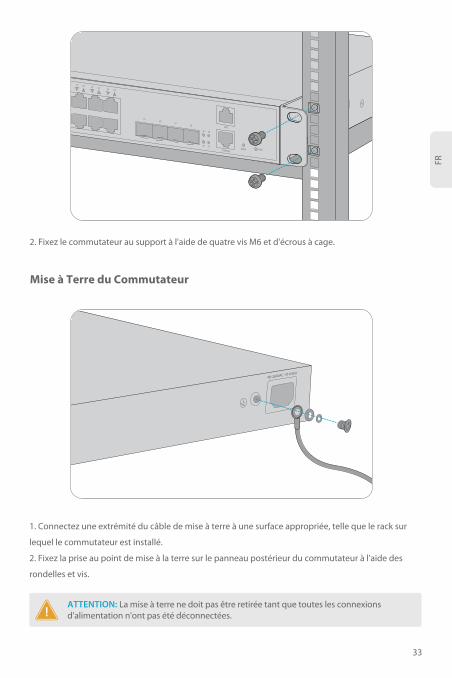
2. Fixez le commutateur au support à l'aide de quatre vis M6 et d'écrous à cage.
1. Connectez une extrémité du câble de mise à terre à une surface appropriée, telle que le rack sur
lequel le commutateur est installé.
2. Fixez la prise au point de mise à la terre sur le panneau postérieur du commutateur à l'aide des
rondelles et vis.
Mise à Terre du Commutateur
90-264VAC 47-63Hz
ATTENTION: La mise à terre ne doit pas être retirée tant que toutes les connexions d'alimentation n'ont pas été déconnectées.
100-240V~, 50/60Hz, 0.8A

FR
34
Connexion des Ports RJ45
1. Connectez un câble Ethernet au port RJ45 d'un ordinateur, imprimante, unité de stockage en
réseau ou autres périphériques réseau.
2. Connectez l'autre extrémité du câble Ethernet au port RJ45 du commutateur.
1. Branchez le câble d'alimentation CA dans le port d'alimentation situé à l'arrière du commutateur.
2. Branchez l'autre extrémité du câble d'alimentation à une source de courant alternatif.
Connexion du Courant
90-264VAC 47-63Hz
AVERTISSEMENT: Ne pas brancher le câble d'alimentation lorsque l'appareil est sous tension.
S3900-24T4S
1 2 3 4 5 6 7 8 9 10 11 12
13 14

FR
35
Connexion des Ports SFP
1. Branchez le module SFP+/SFP compatible sur le port SFP+.
2. Connectez le câble à fibre optique au module émetteur-récepteur. Ensuite, connectez l'autre
extrémité du câble à un autre dispositif à fibre optique.
Connexion du Port Console
1. Branchez le connecteur RJ45 dans le port RJ45 de la console situé sur le panneau frontal du
commutateur.
2. Branchez le connecteur femelle DB9 du câble de la console au port série RS-232 de l'ordinateur.
18 19 20 21 22 23 24
25
25
26
26
27
27
28
CONSOLE
MGT
SYS
PWRRESET
28
Connexion des Ports de Gestion
AVERTISSEMENT: Les rayons laser peuvent causer des lésions oculaires. Ne pas regarder dans les orifices des modules optiques ou des fibres optiques sans protection oculaire.
36
FR
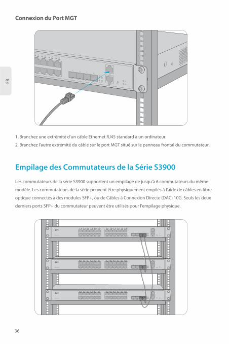
Connexion du Port MGT
1. Branchez une extrémité d'un câble Ethernet RJ45 standard à un ordinateur.
2. Branchez l'autre extrémité du câble sur le port MGT situé sur le panneau frontal du commutateur.
17 18 19 20 21 22 23 24
25
25
26
26
2728
27
28
SYS
PWRRESETCONSOLE
MGT
Empilage des Commutateurs de la Série S3900
Les commutateurs de la série S3900 supportent un empilage de jusqu'à 6 commutateurs du même
modèle. Les commutateurs de la série peuvent être physiquement empilés à l'aide de câbles en fibre
optique connectés à des modules SFP+, ou de Câbles à Connexion Directe (DAC) 10G. Seuls les deux
derniers ports SFP+ du commutateur peuvent être utilisés pour l'empilage physique.
S3900-24T4S
1 2 3 4 5 6 7 8 9 10 11 12 13 14 15 16 17 18 19 20 21 22 23 24
25
25
26
26
27 28
27
28
SYS
PWRRESET
CONSOLE
MGT
S3900-24T4S
1 2 3 4 5 6 7 8 9 10 11 12 13 14 15 16 17 18 19 20 21 22 23 24
25
25
26
26
27 28
27
28
SYS
PWRRESET
CONSOLE
MGT
S3900-24T4S
1 2 3 4 5 6 7 8 9 10 11 12 13 14 15 16 17 18 19 20 21 22 23 24
25
25
26
26
27 28
27
28
SYS
PWRRESET
CONSOLE
MGT

FR
Configuration du Commutateur à l'Aide de l'Interface Web
Configuration du Commutateur
Welcome to FS Ethernet Switch
English
Sign in
admin
******
Étape 1: Connectez votre ordinateur au port de gestion ou à tout port Ethernet du switch à l'aide du
câble de réseau.
Étape 2: Définissez l'adresse IP de l'ordinateur à 192.168.1.x.("x" est un nombre compris entre
2 et 254).
? x
OK Cancel
General
I P a d d r e s s :
S u b n e t m a s k :
D e f a u l t g a t e w a y :
Y o u c a n g e t I P s e t t i n g s a s s i g n e d a u t o m a t i c a l l y i f y o u r n e t w o r ks u p p o r t s t h i s c a p a b i l i t y . O t h e r w i s e , y o u n e e d t o a s k y o u r n e t w o r ka d m i n i s t r a t o r f o r t h e a p p r o p r i a t e I P s e t t i n g s .
Internet Protocol Vers ion 4 (TCP/ IPv4) Propert ies
Use the fol lowing IP address :
Obtain an IP address automatical ly
Preferred DNS server:
Alternate DNS server:
Validate settings upon exit A d v a n c e d . . .
. . . 21168192
0255255255
. . .
. . .
. . .
. . .
Obtain DNS ser ver address automatical ly
Use the fol lowing DNS ser ver addresses :
Étape 3: Ouvrez un navigateur, tapez http://192.168.1.1, et entrez le nom d'utilisateur et le mot de
passe par défaut, admin/admin.
Étape 4: Cliquez sur Connexion pour afficher la page de configuration en ligne.
37

FR
1.Après avoir configuré l'empilage, les deux derniers ports 10G disparaîtront du fichier de
configuration, ce qui est normal. Cette conception a pour objectif d'éviter les erreurs de
fonctionnement.
2.Si vous utilisez le DAC comme câble d'empilage, le DAC 1-3m est recommandé.
Dépannage de la configuration des empilages
Configuration du Commutateur à l'Aide du Port de Console
Dépannage
Dans le cas de câbles et d'émetteurs-récepteurs compatibles, le port n'est pas en service. Veuillez
modifier le mode du port pour adapter ou forcer la vitesse du port à 1G/10G.
Le port 10G ne fonctionne pas
Étape 1: Connectez un ordinateur au port de console du commutateur à l'aide du câble de
console fourni.
Étape 2: Démarrez le logiciel de simulation de terminal HyperTerminal
Étape 3: Définissez les paramètres HyperTerminal: 115200 bits par seconde, 8 bits de données,
aucune parité, 1 bit d'arrêt et pas de contrôle de flux.
Étape 4: Entrez le nom d'utilisateur et le mot de passe par défaut, admin/admin.
xQuick Connect
Protocol: Serial
Flow Control
DTR/DSR
RTS/CTS
XON/XOFF
Save sessionShow quick connect on startup
Open in a tab
Connect Cancel
COM3
115200
8
None
1
Port:
Baud rate:
Data bits:
Parity:
Stop bits:
Name of pipe:
38
FR
FS garantit à ses clients que tout dommage ou article défectueux dû à notre fabrication, peut être
retourné gratuitement dans les 30 jours suivant la date de réception de la marchandise. Cela exclut
tout article fabriqué sur mesure ou toute solution personnalisée.
Soutien et autres informations
Télécharger
Centre d'Assistance
Contactez-Nous
https://www.fs.com/fr/products_support.html
https://www.fs.com/fr/service/fs_support.html
https://www.fs.com/fr/contact_us.html
1. Testez la connectivité du réseau par ping.
2. Si le réseau est joignable, essayez de redémarrer le commutateur.
3. Vérifiez si le service correspondant est activé.
Connexion à distance du commutateur sans succès
Le port ne fonctionne pas, l'indicateur LED est éteint
1. Assurez-vous que les ports de commutation sont en état de non-arrêt (No Shutdown).
2. Vérifiez si le commutateur peut détecter les informations du DDM.
3. Vérifiez si le paramètre de vitesse du port est correct.
4. Essayez de faire passer le câble du commutateur en boucle.
Garantie des Produits
Garantie : Les commutateurs de la série S3900 bénéficient d'une garantie limitée de 4 ans contre
tout défaut matériel ou de fabrication. Pour plus de détails sur la garantie, veuillez consulter le site
https://www.fs.com/fr/policies/warranty.html
Retour : Si vous souhaitez retourner un ou plusieurs articles, vous trouverez des
informations sur la procédure à l'adresse suivante
https://www.fs.com/fr/policies/day_return_policy.html
4
39

Compliance Information
FCC
Note: This equipment has been tested and found to comply with the limits for a Class B digital device,
pursuant to part 15 of the FCC Rules. These limits are designed to provide reasonable protection
against harmful interference in a residential installation. This equipment generates, uses and can
radiate radio frequency energy and, if not installed and used in accordance with the instructions, may
cause harmful interference to radio communications. However, there is no guarantee that
interference will not occur in a particular installation. If this equipment does cause harmful
interference to radio or television reception, which can be determined by turning the equipment off
and on, the user is encouraged to try to correct the interference by one or more of the following
measures:
—Reorient or relocate the receiving antenna.
—Increase the separation between the equipment and receiver.
—Connect the equipment into an outlet on a circuit different from that to which the receiver is
connected.
—Consult the dealer or an experienced radio/TV technician for help.
This device complies with part 15 of the FCC Rules. Operation is subject to the following two
conditions: (1) This device may not cause harmful interference, and (2) this device must accept any
interference received, including interference that may cause undesired operation.
CAUTION:
Any changes or modifications not expressly approved by the grantee of this device could void the
user's authority to operate the equipment.
Responsible party (only for FCC matter)
FS.COM Inc.
380 Centerpoint Blvd, New Castle, DE 19720, United States
https://www.fs.com
40

FS.COM GmbH déclare par la présente que cet appareil est conforme à la Directive 2014/30/UE et
2014/35/UE. Une copie de la Déclaration UE de Conformité est disponible sur
https://www.fs.com/fr/company/quality_control.html
Die FS.COM GmbH erklärt hiermit, dass dieses Gerät mit der Richtlinie 2014/30/EU und 2014/35/EU
konform ist. Eine Kopie der EU-Konformitätserklärung finden Sie unter
www.fs.com/de/company/quality_control.html.
FS.COM GmbH hereby declares that this device is in compliance with the Directive 2014/30/EU and
2014/35/EU. A copy of the EU Declaration of Conformity is available at
www.fs.com/company/quality_control.html
FS.COM GmbHNOVA Gewerbepark Building 7, Am Gfild 7, 85375 Neufahrn bei Munich, Germany
FS.COM LIMITED 24F, Infore Center, No.19, Haitian 2nd Rd,Binhai Community, Yuehai Street,Nanshan District, Shenzhen City
CE
41
Copyright © 2021 FS.COM All Rights Reserved.
Q.C. PASSED
5853