Embed Size (px)
DESCRIPTION
3Kw engine and engine configuration reviews
Citation preview

'4~ ~ 1v*~~;*~ 1 , . W'
AA,'
IN
.
, tP,
-41
(~4
.*1 V .
A9 0,7,.1
1ý ~ X4.ý
1''ij
4. 4 4.OW N

II.~.................................
Unclassified.SECUR ITY CLASSIFICATION OF THIS PAGE (W'hen Date Entered)
READ IP'STRUCTIONSREPORT DOCUMENTATION PAGE, BEFORE COMP'LETING IOKM
I. REPORT.NUMEER _F.GV rCSI.4N 3. FIECIPIENT'S CATALOG INUME
ItFlow RTD Repo~rt No. 242 _____
4. TITLE tedSbil)5.TYP* OF REPC.RT &. PERIOL) COVERED
Development of a Quiet Stirling %;ycle Multi-- Final92 Repo t.18 DFuel Engine for Electric Power GenerationFb.18 -Au 92
____ ____ ____ ___ ____ ___ ____ ___ RTD No. 242 .
7. AUTHOR(s) 2. CONTRACT OR ORANT NI)MSIE Ri)
J. E. Mercer G. L. TremouletS. G. Emigh M. A. White DAAK7O-82-C-0046P. Riggle9. PERFORMING ORGANIZATION NAME AND ADDRESSES 10. PIROGRAM ELEMENT, PROJECT, TASK
~ ~1 ~~Flow Industries, Inc. AE OKUI UBR
21414 - 68th Avenue South IL162733AH20-EEKent, WA 98031 _____________
y I11. CONTROLLING OFFICE NAME AND ADDRESS 12. REPORT DATE
U. S. Army Mobility Equipment Research &August 1982Development Command - Attn: DRDME-EM 13. NUMWER OFPAGES
Fort Belvoir, VA 22060 38 _____
14. MON!TORING AGENCY NAME & ADDRESS 15. SECURITY CLASS. (of this reporrt
J.)J'r~~t rwn .Jnrnl ingOff-v)Unclassified
15m. DECLASSIFICA7ION/DDWNGRADING
SCHEDULE
r ~16 DISTRIBUTION STATEMENT lof this Report)
Approved for public release; distribution unlimited.
17 DIST RI BUT ION STATE ME NT tof the abstrp( ?entered in Block 20, ifdifferent from Report)
18 SUPPLEMENTARY NOTES 4
I9 KEY WORDS 1Con irinseC on reverie side ifnecessaty and identIfy by block number)
Mobile Power Unit
Stirling Engine
ABSTRACT (Con tin'*e OPI reersrseside if necesiary and identify by block number)
The work described in thie report summarizes a six-month study to develop alightweight, tactical electric power plai~t with a low level of aural, I.R.,and visual detectability, based on a Stirling engine. The conceptual designpresented was analyzed and predicted to have power output qualities exceedingthose specified by the Army for tactical generators. The unit promises to
have maintenance and overhaul requirement characteristics superior to anygenerator system in current use.
FOR~JM 143 EDITION OF I NOV 6515 I ýULETE Ucasfe
SECURITY CLASSIF ICAT ION OF THIS PAGE [When Date Entceredi

Research and Technology DivisionArmy Stirling Progress ReportAugust 1982
Foreword
This report was prepared at Flow Industries, Inc., 21414-68th Avenue
South, Kent, Washington under Contract No. DAAK70-82-C-0046.
This project was !unded under Phase I of the Defense Small Business
Advanced Technology (D-SAT) Program. Contract and technical
monitoring of the project was provided by the U.S. Army Mobility
Equipment Research and Development Command, Electrical Power
"Laboratory (MERADCOM, DRDME-EM), Ft. Belvoir, VA. The
Contracting Officer's representative was Mr. Herb Rothschild
(DRDME-FL) and the 4technical representative was Mr. W. A.
Suminerson (DRDME -E M).
A0o•e82on For
DTIC TAB0!!•,. tnanuoun)ed
[ Availability Co4._
• ~D~lut S $oo~a31,
•.*

Research and Technology Di£vsionArmy Stirling Progress Report CAugust 1982
Acknowledgement
The authors grateful'v acknowledge *che assistance provided by
Mr. W. A. Summerson and Mr. P. Arnold of the U.S. Army Mobility
Equipment Research and Development Command, Electrical Power
Laboratory (DRDME-EM), Ft. Belvoir, VA for their guidance in
defining the design parameters for the Stirling engine mobile
electrical generating unit. Also the authors wish to acknowledge
Dr. Hung Huynh of Flow Industries, inc. for performing the computer
analysis of the design.
k€
I €I
II
S•',-:••9- , •r''••ll~• ¢r•.•-j-•." ... ...... . ., • ,•-• * C

Research and Technology DivisionArmy Stirling Progress ReportAugust 1982
-ill-
S Table ot Contents
Item Page
1. Abstract I
2. Introduction
5P 3. Objective 2
4. Approach 2
5. Discussion 3
A. Army Requirements 3
B. Stirling Engine Concept Reviewed 3
C. Conceptual Design of a 3 kW Stifling
Ringbom Generator System 15
D. Computer Simulation 31
6. Conclusions 35
h6

Research and Technology Division& Army Stirling Progress Report
August 1982
-Iv-
List of Figures and Tables
PageFigure 1. Concept Diag, n, Free Piston Stirling Engine 6
with Linear AIternator
Figure 2. Free Piston Stirling Hydraulic Concept Based 8
j Ion a 15 kW Solar Engine StudyFigure 3. Forced Displacer, Free Power Piston Stirling 10
Hydraulic Concept
Figure 4. Free Displacer Ringb)m Electric Concept 12Figure 5. Forced Displacer Ringbom Electric Concept 14Figure 6. Energy Flow Chart 18Figure 7. Stirling Ringbom Conceptual Layout 24Figure 8. Displacer Support ',Flexure) 25
* Figure 9. Schema-tic Control System for Forced Displacer 28
Ringbom Stirling EngineFigure 1 0. Displacer and Power Piston Frequency as 33
a Function of Time* Figure 1I. Power Output from the Stirlinp.IRineboi as r '44
Function of Phe,se Angle
Figure 12. Transcience Performance 36Figure 13. Transcience Performance 37Figure 14. The Effect of Load Rejection 38
Table I. Flow Industries Evaluation of the Free Piston 5Stirling LiPear Alternator Concept
Table 2. Flow Industries Evaluation of the Free Piston 7
Stirling Hydraulic System Concept
Table 3. Flow Indstries Evaluation of the Forced Displacer, 9Free Power Piston Stirling Hydraulic System Concept
Table 4. Flow Industries Evaluation of Free Displacer Ringbom I I
Electric System Concept
Table 5. Flow Industries Evaluation of Forced Displace Ringbom 13
Electric System Concept
Table 6. Preliminary Engine Specifications 23
Research and Technology DivisionArmy Stirling Progrest; Report
*P August 1982
1. ABSTRACT
The work described in this report summarizes a six-month study to develop a
lightweight, tactical electric power plant with a low level of aural, i.R., and visual
detectability, based on a Stirling engine. The conceptual design presented was
analyzed and predicted to have power output qualities exceeding those specified bythe Army for tactical generators. The unAt promises to have maintenance and
overhaul requirement characteristics superior to any generator system in current use.
2. INTRODUCTION
For several years, the Army has been sponsoring a program to develop a family of
Silent Lig-twe*ght Electric Energy Plants (SLEEP). The gerneral requirements of the
program are to design lightweight, compact, reliable, easily transportable, multifuel
electrical generating devicesF that will be difficult to detect by visual, aural and IR
means. The principle uses for the devices will be to provide power forcommunications equipment, command posts, visual and IR illumination devices,
maintenance equipment, ground surveillance radar, battery chargers, and combatvehicle needs.
".evelopmnts. In Stirling engines over the last several years have made these
engines viable candidates for the SLEEP program. The Stirling engine is an external
combustion engine, which can run on a multitude of fuels, rAnging from the typical
military liquid fuels such as gasoline, diesel, JP4 a.)d JP5, to solid fuels such as coal or
even wood. This range of fuels greatly enhances the probability thai the device will
be operational when needed.• !i Personnet currently involved in major design advances for Flow Industries' Stirling;
engine program have been actively involved in Stirling technology for over twenty
years. Most of these advances have been associated with a prcgram sponsored by the
Natioml Institute of Health, in efforts to develop a power source for artificial
hearts. The current technology for a Stirling engine heart pump power source is at the
stage %Ioere a 10-year maintenance-free life is achievable. Operational units have
already been running continuously for more than 4 years without maintenance.
Critical components in the design have beer. tested and theorized to have almost
infinite life. Studies performed at Flow have demonstrated that the heart power
source can be scaled to large engines, as was documented in a report to NASA on
scaling up to a 15 kW output model (NASA OR-I 59587).
!1
2" : - " " . . _ . I _ __ ' " I I _J • I I I I I I lI I II I ~ I I I

- - - "-•..... . • • •"•- = • .. . . > • - 70 U "T '" " *-, r•i -= , .... , ..... .. ,
Research and "Technology L)ivision.Army Stirling Progress ReportAugust 1982
-2-
The work described in this report was sponsored by the Defelise Small Business
Advanced Technology (DESAT) program. The total effort is divided into two phases.
The Phase I portion of the study, presented in this report, was ':o derive a design
methodology that would lead to the development of a Stirling e~igine-based engine
generator set. This report describes a Stir'ing-Ringborn conceptual, design that has a
3 kW electrical power r-utput. The goal of the design effort was to achieve a
maintenance-free engine by scaling up the basic heart engi;.e design. Phase 2 of the
effort will be to detail the conceptual design of this report and build a demonstration
unit.
3. OBJECTIVE
The objective of the work presented in this report was to develop a design
methodology that would allow application of Stirling engine technology to
engine-generator sets. The work was divided into 3 tasks:
I. Define an end use that will meet tie Army's needs, ncludirig equipment
requirements.
2. Select an engine configuration to nmeet the requirements as defined above.
3. 2valuate the feasibility of the 5elected engine conf igural ion.
The effort described here covers a six-month period. A conceptuai design
meeting the requirements developed in Task I above is presented, and formi the basis
"f or a Phase 2 effort, which will be the construction of a demonstration unit.
4. APPROACH
In order to best define the Army's needs, a review me,'ting was held with
MERADCOM personnel at Ft. Belvoir, Virginia. Discussions resulting from this
meeting established a set of requirements for a power plant thai would best meet the
Army's needs. The SLEE P program was identified as a good application for Stirling
engine technology.
Once a general set of requirements was established, a review of past work in
Stirling engine development was made by drawing from experience gathered during
15 years of work by Flow personnel on a Stirling, heart purip. After comparing the
Army's requirements for a Stirling-powered generator with the capabilities of
03
-

!I - - Research and Technology DivisionArmy Stirling Progress Report
-3- August 1982• -3-
state-of-the-art Stirling technology, a comparative analysis was performed on fivwStirling engine concepts. We then selected the best of these concepts, determined
preliminary sizing and specifications, and produced a conceptual layout. Next, we
performed a computer analysis of operation under startup, steady state and transient
conditions, and the results were compared with the requirements set by
MIL-STD-I 332B.
5. DISCUSSION
A. ArM ye qur ments
The Army's requirements were identified as a result of discussions with
MERADCOM personnei, and were based on the SLEEP program. They are aimed at
developing a lightweight, low detectability, tactical electrical power source. Eightpoints for consideration were brought out in the discussions. They are:
I. Selection of the working fluid (air, hydrogen or helium).
2. Power density characteristics of the kinematic versus Ringborn designs.
3. Efficiency.
4. Trade-offs (e.g., performance versus field serviceability).
5. Serviceability.
6. Ambient temperature and altitude in service conditions.
7. Fuels (gasoline, diesel, JP4 and JP5).f 8. Cost.
These points are covered in this section as part of the various design
considerations and trade-off studies. The range of engines applicable to the study
covered 0.5 kW to 10 kW. As a result, the study concentrated on a 3 kW design, since
this was in the middle of the size range and could be easily scaled up or down to cover
the limits. This section presents the results of the study and addresses the points
listed above.
B. Stirling Engine Concepts ReviewedFive free piston Stirling engine concepts were reviewed and arc. summarized as
follows:
I. Free piston with linear alternator output.
2. Free piston with hydraulic power output.

S'Research and Technology DivisionArmy Stirling Progress ReportAugust 1982
-4-
3. Forced displacer with free power piston, aod hydraulic output.
4. Free displacer Ringbom with rotary crank output.
5. Forced displacer Ringbom with rotary crank output.
Tables I through 5 and Figures I through 5 compare the five Stirling designs
considered in Phase I.
Five criteria were selected for evaluation:
* Noise level: Stirling engines do not have the combustion noise problcns
associated with internal combustion engines. They do have limited combustor noise,
which can be easily muffled. The predominant noise comes from the cooling fan.
One means to overcome this noise problem is to use a large diameter, low speed fan
with acoustic treatment on the shroud. Efficient fan designs will also help reduce the
sound level. In general, the Stirling engine should be very quiet, as a result of inherent
low noise levels and the use of standard noise reduction techniques.
Performance: The performance of the Stirling engine is very high compared to
other engines. For the 3 kW range, aa efficiency of about 40% should be achievable.
Higher efficiencies could be expected for larger engines.
Reliability: The Stirlinu heart nower source nropranj has demonstrated that very
reliable Stirling engines can be bu:lit. The novel design "echniques developed for the
heart engine can be used for an electrical generator unit. These designs actually
reduce produc Zion costs when compared with less reliable designs.
• Transportability: The power density of the Stirling engine becomes quite high
when using helium and a high working gas pressure. This translates into a very
portable, lightweight design. A 3 kW unit meeting the Army's service standards will C
weigh less than 300 pounds.
* Maintainability: The design concepts presented in this report allow the entire
engine/alternator assembly to be sealed much like a home refrigerator compressor
unit. This would produce years of trouble-free service. By combining the
engine/alternator unit with other modular units, maintenance can be greatly
simplified. The combination of high reliablity and low maintenance will greatly
enhance the availability of the unit, and assure its mission-ready status.
St~V
• " .... • ,.•. .. .• • •:2 .•" •, • ,.-: •' '• • I•' • • ' ! I4
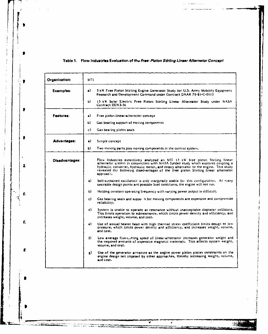
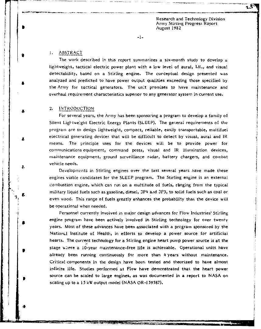
Table 1. Flow Industries Evaluation of thw Free. Piston Stirling Linear Alternator Concept
* Organization: MTI
Examples: a) 3 kW Free Piston Stirling Engine Generator Study for U.S. Army Mobility EquipmenxResearch and Development Command under Contract DAAR 70-81-C-01 13
b) 15 kW Solar Electric Free Piston Stirling Linear Alternator Study under NASA
Contract DEN 3-56
Features: a) Free piston linear-alternr-tor concept
b) Gas bearing support of moving components
c) Gas bearing piston seals
Advantages: a) Simple concept
b) Two moving parts plus moving components in the control system.
Disadvantages: Flow Industries extensively analyzed an MTI 15 kW free piston Stirling linearalternator system in con)unction with NASA funded stud) which explored coupling ahydraulic converter, hydraulic motor, and rotary alternator to the engine. This studyrevealed th0 following disadvantages of the free piston Stirling linear alternatorapproac'i.
a) Self-sustained oscillation is only marginally stable for this configuration. At manyoesirable design points and possible load conditions, the engine will not run.
"b) Holding constant operating frequency with varying power output is difficult.
"c) Gas bearing seals and suppo -s for moving components are expensive and compromisereliability.
d) System is unable to operate at resonance without unacceptable displacer collisions.This limits operation to subresonance, which limits power denmity and efficiency, andincreases weight, volume, and cost.
e) Use of annual heater head with high thermal itress coefficient limits design to low
pressure, which limits power density and efficiency, and increases weight, volume,and cost.
1) Low average flux-L..tting speed of linear-alternator increases generator weight andthe required amounts of expensive magnetic materials. This affects system weight,volume, and cost.
g) Use of the generator armature as the angine power piston places constraints on theengine design not imposed by other approa.hes, thereby increasing weight, volume,ad cost.
II
" I)I
Suggestec Control for lb kW Solof EngineVariable Volume Di&olacer Bounce Chamber(Change% Disolacer Natural Fequency)
Gas l'~oetr
Displacer Bounce DiameterWith Gas Bearing Displacer
|.- Suspension and Pisto,, Seal
.t--, Regenerator
Gas Cooler
-______.,Combined Power Pistonand Flux Switch with Gas
.7.I Bearing Suspension and Seel
Makeup SystemsOmitted for Clarity
Concept Diagram, Free Pistorn Stirling Enginewith Unear Alternator
Figure I
C
z'-
I. eU

S
Table 2. Flow Industries Evaluation of the Free Piston Stirling Hydraulic System Concept
Organization: University of Washington, 3oint Center of Graduate. Study (3CG)
SExample. Free piston Stirling hydraulic enginie for Artificial Heart Power Sk-urce Project funde.di continuously by NIH since 1%7. Development has progressed to an advanced stage with
high performance and m'any years of continuous life testing with engines and critical-__components.
Organization: Flow lndustries/3CGS (rontractually constrained to MTI engine portion design)
Example: Conceptual Design and Cost Analysis of Hydraulic Output U;Lit for l1 kW Free PistonStirling Engine. NASA Lewis Research Center, Contract DEN3-212. The engirn used inthis conceptual design was an MTI 15 kW design originally intended fo, use with a linearalternator. Dynamics of both the Stirling hydraulic approach and t0e Stirling linearalternator approach were studied extensively.
Features: a) Proprietary "dry inertia" power piston. Pressure-balanced, fully-lubricated powerpiston, sealed by hermetic pressure-balanced metal Žel'ows.
b) Uses gas b, r arinr for displacer drive sedh.
c) Uses off-the-shelf hydraulic motor and off-the-shelf genera*,cr or alterrator.
d) Power piston motion dynamically balanced. Displacer piston motion uiibalanced.
Advantages: a) Retains many of the advantages of the demonstrated Stirling hydraulic approachdeveloped for long life artificial heart power source application.
b) Off-the-shelf hydraulic motor and electric generator or alternator require nodevelopment.
c) Cenerator frequency is decoupled from engine frequency, allowing prealical controlto maintain constant frequency.
Disadvantages: a) Self-sustained t,3cillation is marginally stable. At many desirable design points andpossible load conditions, the engine will not run.
b) Gas bearing displacer drive seal and support is expensive and may compromisereliability.
c) Compromised powe,- density. Cannot operate 0t resonance without experiencingdisplacer and power bellows collisions.
d) Partidly unbalanced. Cannot employ dynamic absorber because operating frequencyshifts with power level.
It
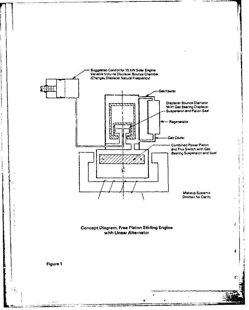
Control by Variable Volume Displcar Bounce Chamber(Changes Displacer Natural Frequency)
Displacer Bounce-- Chamber With Gas
Bearing Displacer Suspensionand Piston Seal
MTI 15 kWSolar St'iing
Engine
Gas Cooler
HydraulicConvertor
by Counterbalance PistonsFlow IndustriesStaff Mlenbers
H ~Oil IMakeup Systems"Omitted for Clarity
Oil' w Prlslew OilPressure Oil
oilAccumul~toro
Electric +O-h-hlLoad 0yrui Moto
Off -the -Shelf E kl--tic l
Generator or Attertor |!1Free Piston Stirliag Hydraulic Concept Based upon a 15 kW Solar Engine
Study for NASA Using an MTI Engine and a Hydraulic Convertorby Flow hidustr!es Staf Members
Figure 2
-- -- -- -- -.- ,
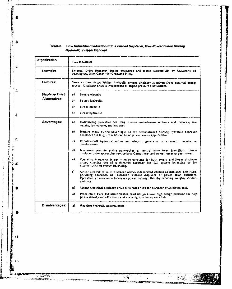
Table 3. Nlow Industrioa Evaluatian of the Forced (i/pbece,, Free Power PItton StirlingHydraulic Sy4stem Concept
Orgaizaton:Flow Industries
Example: External Drive Research Engine developed and tested successfully by University ciWashingtont, 3oint Center fnr Graduate Study.
Foutures: 'Name as free piston Stit-ling ýhydraulic except displacer is driven from extcrnal energysource. Displacer drive is independent of engine pressure fkuctuations.
Displacer Drive a) Rotary electricAltrntivs: b) Rotary hydraulic
0) Linear electric
d) Lintax hydraulic
Advantages: a) Outstandlap. potential ter' long mean..time-between-overhauls and failures, lowweight, low volume, and low cost.
b) Retains many of. the ldvantagtvs of the demonstrated Stirling hydraulic approachdeveloptd for leng life artific.4kI heart power source applicztfion.
.) Off-vhe'.shelf hydraulic: motor and electric generator or aCternator require nodevelopment.
d) Numetrous possible stable approaches to contro! have been identified. LinearIdisplacer drive approaches reduct both Carnot heat and reheat losses at part power.
0e ~imrating f req~uency is easily made constant for b-oth rotary. and linear displacerdrive, allowing use of a dynamic absorb~er for l ull system Weancing or for;.ugmentý.tin of tyttem bal&'ncing.
f) Un'::ar electric drive of disp~lacer allows independent control of displacer amplitude,prw)iding operation at rez-onance without displacer or power train collisions.Op'-ration at resonance increases power denbity, thereby reducing weight, volume,znd cvai,
g) Linear electrical displacer drive eliminates need for displacer drive piston see..
Diava~taes 6~) Proprietary Fluw Indisvrioes heater head de,%isn allows high design pressure, for- high
pIwrdniyzsefLec n o ejt oue n ot
04detgs ) eurshdali cunaos

Hot Fezure Dwupoms Sw*spensior// (COed Flex. at Othm Lid)
Gas H ester
Uiner ElectricDispisczr Drive -
pMicroprocmoSr Conr~tol jsCoe
-Engine C24o
Pimsurt Balanced Hermetic(-ýL~ar FreuencyMeW Do lo~ws at Engine
Control rs Frmure
Prew. re B larncu HermeticMetvY Balliws ot Buffer
Return Prm~ure Accumutator(ApproximrteIy 100 pabi.) Supply ý,vwure Accurnu~ator
(Appwodfrrtely 5,000 Pasa)
Ott 4t-ShelfE)crCLO-- - Hydtaulic Motor
0-fti La
ForcGd Displacer, Free Power Piston StIrclno Hvdraulk Conceptwith Microprocessor Controlled Linear Electric Drives System~
Figure 3
-7,

Table 4. Flow Industrios Evaluation of Fre h vWa~rRlngbomV E Mcr SY~ltemConcept
Organization: -~Flow Industries
Feaurs:Same as free piston Stirling hydraulic except power raiston Is coupled directly to rotary
a) Crank or yoke connects pressura-bailanced power piston with flywheel, which drivesStimerstor or alternator.
b) Counter-rotating flywheels for complete dynarnic balance.
c) Overdriven free piston displacer drive with top-end tuning.
d) OffMthe-s helf rotary alternator or generator.
e) Hydralilic motor is not required.
Advantages-, a) Pressure-balanced power piston greatly reduces power trikin bearing loaf,,power-train friction losses, and required flywheel rmassý
h) Retaiins many of the advantages of the demonstrated Stirling hydraulic approachdeveloped for long life artificial heart power source application.
c) Oif-t he-shelf alternator 0? generator requires no development.
d) CopernItely ha!anced !or srFnooth, quet. vIbration-free powt~r.
Disadvantages: a) Control mode to provide precise frequency control viot identified.
b) Two small flywheels are required.
c) Displacer drive piston seal not identified. Gas bearing shown In concept diagram
considered unacceptable for reasons of cost and reliability.
r
11
7 C.
IiEngine tas
Y., Hermetic MetalBellows PressureBalanced at EngineP msure
W~ffor Gas
Oil
-Hermetic Metal Bltiows.Pressure Balanced atBuffeor Gas Presure
-' - Cross Head with DuelConnecting Rod&
-Atmospheric Crankcase
Generator or Alternator
X-Dual Flywheels AllowFulBalancing
_ _ _ _ _ _
Makeup Systems Omittedfor Clarity
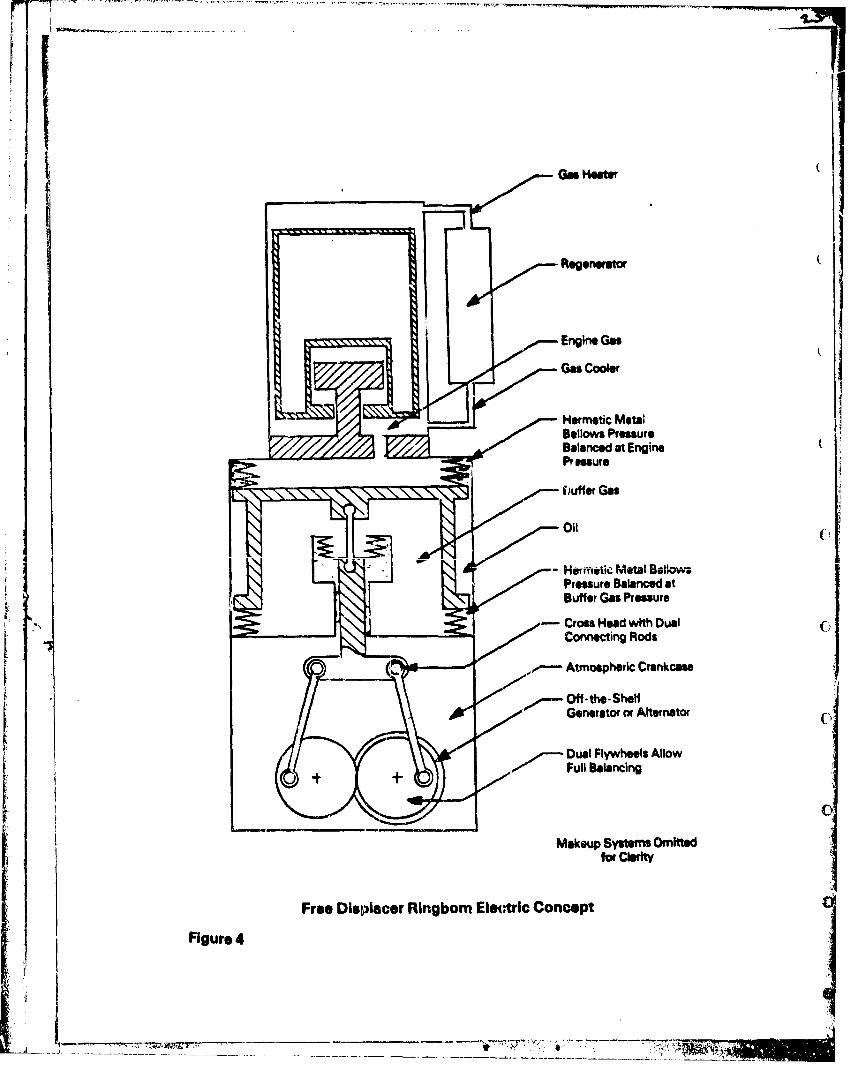
Free Displacer Ringbomn Electric Concept
Figure 4
M7_______-~~-

TableSl. Flow Industries Evaluation of Forced D4sp/.cer Ringbom Electric SyStm Concept
Organization: Flow Industries
Features: Same as free displacer RingLrm except that the displacer is driven from an externalenergy source. The displacer drive is independent of the engine pressure fluctuations,allowing steady operation at a specified frequenc.y, regardless of the load.
Displacer Drive a) Rotary electricAlternatives: b) Rotary Hydraulic
c) Linear electric
d) Linear hydraulic
Advantages: a) Outstanding potential for long mean-time-between overhauls and failures, lowweight, low volume, and low cost as demonstrated by the long-life, artificial heartpower-source application.
b) Pressure-balanced power piston greatly reduces power train bearing loads, powertrain friction losses, and required flywheel mass.
c) Retains many of the advantages of the demonstrated Stirling hydraulic approachdeveloped tor long-life, artificial heart power-source application.
d) Off-the-shelf alternator or generator requires no development.
e) Completely bala,)ced for smooth, quiet, vibration-free power.
1 f) Proprietary Flow Industries heater head design allows a high design pressure for highpower density and efficiency, and low weight, volume, and cost.
g) Numerous possible stable control approaches have been Identified. One sim'decontrol concept is a displacer drive using a synchronous motcr. The engine operatesat constant frequency with engine iorque automatically adjusting to load torque.Engine reheat loss does not decrease at partial load, but Carnot heat does. Thelinear displacer drive alternatives allow microprocessor control of the stroke, whilemaintaining a constant frejuency. The linear drive reduces both reheat joss and
Carnot heat when operating at partial power.
h) Linear Electrical d.splacer drive appruach eliminates the need for displacer drivepiston seal.
i) Operating at a consiant frequency allows the use of a dynamic absorber for fullsystem t•alanclng or augmentbtion of system balancing. U a dynamic absorbev" is used
for full byct.em balanciLnr, only one flywheel is required.
Disadvantages: a) One small tlywhee; is required.
_____ _____________________
~!
K -.

IT7I
Micr~processor ControlAdjusts Displacer Amplitude
Current
Engine GasPm e
,.Hermefti Meol Belows$(Pressure Balanced at
Engine Gias Pressure
Crntro - edOniClecig o
Scotch Yoke Optional
Off-the-Shelf Gaweator or
Makeup Systems Omittedow Cfty
Forced IDL-..,>cer Ringboto Electric Concept Shown withUnear Elecreric Diatplac@w Orive
Figure 5

Research and Technology DivisionArmy Stirling Pr)gress Report
*I August 1982
-l5-
Displacer contro! techniques were examined and classified into two categories:
5' (a) free displacer; and (b) forced displacer. The free displacer uses a form )f natural
tuning to control the engine. The mass of the displacer acting against a gas spring
provides the control parameters. The spring constant can be varled by changing the
volume of the cavity containing the "spring" gas (bounce chamber). This Is generally a. •very sensitive control parameter, so that small changes in bounce chamber volume can
cause large changes in power output. The forced displacer overcomes the problems of
the free dispa.cer by providing good control. Many different schemes can be used to
provide the drive for the displacer. These include:
- Hydraulic actuator
Separate crankshaft (not connected to power piston)
o•)lenoid (electrical actuation).
(" A hydraulic actuation system has been used in the heart power source and for the
output on a 15 k\V conceptual design. The hydraulics add complexity and cost to the
system. A solenoid drive is the simplest system and does not require any seals. The
electrical drive for the displacer can be 3utomatically controlled to compensate for
(. load changes and start-up. The simplicity of the solenoid drive made it the preferred
system for the engine/alternator unit.
Three working gasses, helium, hydrogen, and air, were considered. Air was
determined to be undesirable due to the low power density that can be achieved witn
C; its use. The safety of helium versus the slightly improved performance of hydrogen
"was a trade-off consideration. Other considerations were the difficulty in containing
hydrogen and the effects it has on metal properties. The result of these
considerations was the conclusion that helium was the best all around working gas.
C. Conceptual Design of a 3 kW Stirling Ringbom Generator System
The complete generator set will consist of:
. Operator control and indicator lights.
tC . Starting system, including igniter.
. Fuel system, including liquid fuel control.
. Combustor.
* Sodium heat pipe.
S . Two-phase cooling system and fan.

Research and Technology DivisionArrmy Stirling Progress ReportAugust 1982
-16-
Noise and infrared attenuation devices.
* Engine/alternator subassembly.
Control system and microprocessor.
Mounting frame.
O2perator Gontrol and Indicator Lights
Flow will use an operator control system that is the ultimate in simplicity...anon-off switch. The operator will also be provided with several indicator lights to
display the status of the system. These lights are used as diagnostic indi',;tors to help
the operator troubleshoot the system.
Starting_.ste m .ncluding Igniter
The starting system will be fully automated, and will operate the entire system
from battery power until the generator comes on line. The battery will power the
displacer drive (400 watts), the fuel pump and combustor air fan (60 watts, total), the
combustor ignition system (300 watts, for a short period during initial ignition stage),
the microcomputer (5 watts), the oil pump (35 watts), and, as required, the Stirling
engine cooline fan (150 watts). The system will include an inverter (12 volt DC to 120
volt AC) to operate these auxiliary units more effectively during startup. A
conventional automobic battery can supply ample energy with reserves many times
the operational requirerients.
"The start switch turns on the microcomputer, which in turn will sequentially
activate the other controls to start the system. We wilt also provide a ready light to
indicate when the system is ready for application of the electrical load. This ready
light will also signal the transfer of the auxiliary electrical load frc the Lbttery to
the generator, which will then recharge the battery.
Fuel •ystemjncluding Liquid Fuel Control
The fuel system consists of a tank, pump, and controls. The fuel control system
will be operated by a microprocessor. Flow Industries' recent success in incorporating
a microprocessor into the design of our 120-kW vertical axis wind turbine, and the
general usage of microprocessors in automotive fuel control, indicates its use in the
present application. Our approach is to use the microprocessor to provide a
combination of continuous and intermittent fuel feed. Continuous fuel feed will be
I;-. *>. *-

Research and Technology DivisionArmy Stirling Progress Report
I9 August 1982
-17-
used from 100% down to about 40% of design loading. Below the lower load level, we
recommend intermittently shutting off the combustor completely, allowing the
thermal inertia of the combustor and heat pipe to power the engine. During
continuous operation, the microprocessor will control fuel flow rates and fuel
temperature to achieve optimal combustor efficiency over the load range. The
transition point from continuous combustor operation to on/off operation will be
determined by comparing fuel consumption under various engine loads for each of the
two modes of operation.
The microprocessor will use measurements of the heater head temperature andC the electrical load to determine the fuel flow rate. The heater head temperature wili
be maintained at the design point for efficient operation, but the rate of head heating
or cooling will vary with engine loading. Thus, by monitoring the heater head
temperature, and using the change in the electrical load as a derivative feedback, a
responsive, stable control of the combustor can be assured.
The microprocessor will also be designed to vary the combustor air flow rate by
varying fan speed in a manner similar to liquid fuel control. The air flow will be
varied in proportion to the fuel flow in order to achieve the high flame temperatures. associated with near stoichiometric combustion.
Co mbustor
We propose the use of a modified furnace combustot to supply the 11.3 kW orC 38,000 BTU/hour of thermal energy to develop 3 kWV (4 HP) of electric power, as shown
in Figure 6. Figure 6 shows the individual components, their power losses, and the
energy flow throughout the entire system.
Recent interest in fuel-efficient home furnaces has resulted in several new
combustor designs far superior to older models. The new designs, incorporating flame
retention burners, have fuel-to-thermal conversion efficiencies up to about 90%. The
remaining inefficiencies result from the latent heat of vaporization contained in the
water vapor. We will investigate these new combustor designs in Phase 2, and modify
£ one of them for use with this system. One of the planned modifications will be a
combustor-air preheater to recover the heat contaled in the combustion gases leaving
the hot sodium heat pipe evaporator. This is necessary to achieve high
fuel-to-thermal energy conversion efficiencies in heating sodium. The 3 kW output*'

DIESEL FUEL
2.0 Ib/hr I-- USEFUL ENERGYS) / r-:73' LOSSES
CHEMICAL
11 .3 kW
COMBUSTOR /) 1.1 kW HEAT LOSS
' ' V'
STHERMAL ]-'
10o.2 kW
•I',HEAT PIPE 0.1 kW HEAT LOSS
0.4kWENGIE WASTE HEATk
MECHANCAL I
MINIMUM 70'
DISPLACER DP.VE ALTERNATOR - LOSSES AND"____ _/_FRICTIONAL WINDAGE
ELECTRICAL•13.8
AUXILIARY COMPONENiSN 0.4 kW COOLING FAN
0.4 kW \ BA'ITERY CHARGER,JUCTONBI COMBUISTOR FAN,J1O FUEL PUMP, OIL PUMP,1•-i -, FUEL HEATER,SELECTRICAL CONTROL SYSTEM
OUTPUT 3Ikw
Energy Flow Chart for 3 kW Forced Displacer RirgbomFigure 6 Stirling Generator Unit
"Figur ,

Research and Technology DivisionArmy Stifling Progress Report
b lAugust 1982
t19-
fuel consumption is 2 pounds per hour (1.1 liters per hour) of diesel fuel. This9 ~correspond's to 0.5 pounds per horsepower-hour.
Thermostatically controlled electric fuel prehe-Aters are also commercially -
available. Since fuel temperature directly contro's the fuel droplet size in the
combustor, use of such a preheater will facilitate efficient combustion.
Most existing Stirfing en3ines use hot combustion gases to directly heat the
heater head on the hot end of the displacer, resulting in inefficiencies and mechanical
problems. The combustion gases, having a low heat transfer Coeffiecient, require a
sur face area much larger than the heater head for efficient heat exchanging. This
$ results in excessive heat loss or an excessively large heater head. A second problem
results from nonuniformities in the flame temperatture of the combustor, caused by
local variations in fuel-to-air ratios. The hottest place! in the flame can overheat theheat exchanger tubes, weakening them and causing blowouts of the high pressure
I working fluid of the engine. To prevent these hot spots, the overall flame
temperatu-e must be lowered, which results in a loss of coinbustor efficiency. In
addition, the tube walls must be rmade thick, wh~ic.h results in excessive thermal
stresses, thermal fatigue, and eventual failure of the tube wall.
2 "he use of a liquid rmetal heat pipe to conduct the combustor energy to th?
do•,i•,e, sistim avoiud• pr'":viousy m.entioned problems, and provides several positive
advantages. First, the heat pipe acts as a therunal transformer. It gathers heat irom
hot combustion gases over a wide area that has a low heat-transfer coefficient, and
- Idelivers the heat across the much smaller area of the heater head to the engine
"workiig gas, which has a high heat-transfer coefficient. This allows the heater head
to be about one-third the size of a combustion -hea, -d heater head, with an
accompanying reductian in weight, volume, and cost. Second, the heat pipe acts as an
isothermal hrat receiver since it cannot be damaged by local hot spots due to the high
thermal corductivitv of the liqu*d metal. This allows the use of thinner tube wails,
which results in weight reduction, and faster, more efficient heat exchange. The fluid
of chojice in the heat pipe is liquid sodiumn, due to its c•sy availability and appropriate
Jr boiling point for this aplication. The heat pipe design can be simplified if the hzat
source is located below the heater lad so that the condensed liquid can be returned
to the pol by gra.'ity flow rather than by wick action. An area of consideration in
heat pipe design is the effect of hydrogen permeation. If hydrogen from the
-S combustion gases permeates the heat pipe wails, thk. sodium boiling point will rise
pM- .-- - - - --- -- - -

Research an6 Technology DivisionArmy Stirling Progress ReportAugust 1982
-20-
until the heat pipe requires higher temperatures to begin conducting. Proven coatings
to prevent this permeation are available and will oe applied as :equired.
The pressure stabilized configuration employed in Flow Industries' advanced
heater head will incorporate a high temperature sodium heat pipe to transfer heat
from the heat source to the gas heater region. Hot spots that cause serious problems
in other designs are thereby eliminated. In the proposed engine, a wall temperature
drop of 20 0 C is predicted. This i- only slightly higher than typical average values
experienced by conver.tion~al heater tubes, but is much less than the additional 50*C to
I0(7C temperature difference usually encounteted between the hottest metaltemperature and the average temperature. A higher average temperature- can
consequently be achieved with substantially lower peak metal temperatures. This
allows the use of less expensive nickel-based alioys instead of the cobalt-based alloys
found on current!y available Stirling engine de5igns. This transitio., significantly
reduces the material cost for the heater head with little or no loss in effective hot gas
temperature.
The use of high temperature heat pipes also enables the gas heatear to be sized for
the working gas ýde of the heat-transfer film coefficient rather than the lower
combustion side coeffi';ient. This factor result7 in less gas dead-volume, which
innproves thc power density of th_ systemt. Further performance gains are possible,
because an annular flow heat exchanger ha. a better ratio o! heat transfer capaLity to
fluid-friction loss than tubular heat exchangers with the same dead-volume.
Safety is another important consideration in the heat pipe design. The liquidK3, sodium planned for use is chemically active and reacts strongly with water.
Nevertheless, it can be used with complete safety by welding the sodium inio a
hermetically sealed chamber. Flow's patented heatcr head design allows all.-we'ded
construction to ensure an effective chamber seal. This metlvd is currently used in
many diesel engines for exhaust valve cooling. Any safety problem reduces to
providing mechanical integrity for the liquid metal contaiser.
Many steel alloys are suitable for containing sodium, and corrosion resistance to
sodium has been well documented by the )uclear industry. Basically, the same
iron-nickel-chromium alloys used for high temperature creep resistance are applicable
for containing sodium.
4.O
---- ---

Research and Technology Division[Army Stirling Progress ReportAugust 1982
Since the Army's long range requirement for the combustor includes the use of
alternate fuels, fuels such as diesel, jet fuel, and gasoline can all be burned efficiently
in the flame retention burners by making minor adjustments.
Sodium Heat Pipe
Two major problems with existing combustion-driven Stirling engines are the
physical size of the heater head and hot spot damage to the heat exchanger tube3.
The use of a sodium heat pipe to conduct the combustor energy to the displacer heater
head has advantages for two basic reasons. First, the heat pipe acts as a thermal
t. transformer, collecting combustor energy over a relatively wide area and delivering it
to a compact heater head. Second, the heat pipe is essentially an isothermal heat
receiver and cannot be damaged by local hot spots in the combustion flow.
Two-Phase Cooling System and Fan
The cold end ci the displacer piston will be most efficiently cooled with either a
heat pipe using ha)ogenated hydrocarbons or a two-phase thermosiphon using one of
the pentane isomers. In either case, no cooling pump will be required, thus avoiding a
known high-maintenance item in conventional internal combustion engines. Thepreferred cooling met~hod will -he selected based u-on consder"Li.... Of ..... ..•=il•,t' and '
ability to operate over the broad range of ambient temperatures encountered (-2pr o m F
to 125PF),
i ( It will be necessary for the evaporator end of the coolant cycle to surround the
"cold end of the displacer piston. i , condenser end of the cycle would best besituated above the displacer in a radiator that is cooled by forced-air conve. tion with
a fan or blower.
The cooling fan will need to draw about 7000 watts from the coolant. It will
operate at reduced air flow velocities to prevent excessive noise generation. To
further reduce noise, special muffling devices could be installed with the objective of
meeting the aural non-detectability requirement a; specified in MIL-STD-147'4b.
Similar muffling devices could also be installed on the combustor air intake and
exhaust.
'p
i --.

Research and Technology DivisionArmy Stirling Progress ReportAugust 1982
-22-
Noise and Infrared Attenuation Devices
The design goal for noise level is to achieve the limiting octave band levels (dB),
as specified in MIL-STD-1474b for aural non-detectability at a nominal distance of
100 meters. To achieve this, the engine noise level measured at a distance of, for
example, 6 meters should not exceed 41 dB for the octave band having a center
frequency of 500 Hz. Design features emphasizing low noise could be incorporated, in
addition to special muffling devices in order to meet the Army's requirements for an
extremely low noise level power source. Special considerations need to be focused on
the combustor air intake and exhaust, cooling fan and its shroud. Lightweight infrared
radiation shields could be incorporated to reduce the infrared signature.
Englae/Alternato r Subassemblv
After a comparative analysis of the five Stirling engine concepts was completed,
the forced displacer Ringbom Stirling was chosen, based upon the previously listed
advantages, found in Table 5.
The proposed design concept employs a helium working fluid and an
electromagnetically driven displacer. Frequency control is accomplished by means of
a crystal-based electronic displacer drive. The design also employs a rotary electricaldevice so that both A.C. and D.C. machinery can be incorporated. System balancing
is accomplished by using harmonic dampers and counterbalances. The system• is
designed to be hermetically sealed, similar to a refrigeration unit, for maximum
reliability.
Preliminary engine specifications and a full-size conceptual layout are shown in
Table 6 and Figure 7. The key elements of the design are discussed below.
The displacer is held concentric within its housing by means of double spiral
flexures at each en6, allowing free axial motion while maintaining a constant gap
between displacer and housing. The basics of this concept are shown in Figure 8. The
displacer drive consists of a crystal-controlled electromagnetic system that drives the
displacer at a constant 60 Hz, once the engine is brought up to full operating speed.
The working gas is heated by heat pipe condensate which collects on the walls of
the concentric tubes through which the working gas passes.
The working gas moves to and from the cooler region through an annular
regenerator.
I7 ;:7:e

Research and Technology DivisionArmy Stirling Progress ReportAugust 1982
-23-
Table 6. Preliminary Engine Specifications 3kWIO)Hz Ringbom GPU
Diameter 6.35 cm (2W50 in.)
£ Stroke 1.27 cm (.50 in.)
Displacement 40 cc (cu. in.)
Power Piston:
Diameter 5.72 cm (2.25 in.)
Stroke 1.17 cm (.46 in.)
Displacement 30 cc (1.83 cu. in.)
Reefnerator:
Outside Diameter 7.30 (2.88 in.)
Inside Diameter 6.68 cm (2.63 in.)
Length 3.81 cm (1.50 in.). Volume 26.6 cc (1.62 cu. in.)
Matrix Density 40% to 50%
Working Gas:
Flow gap (heater and cooler) .064 cm (.025 in.)
Pressure 13.8 + 5.5 mpa (2000 .800 psi)
Gas Helium
U Buffer Gas-
Pressure 1 3.8 mpa (2000 psi)
Volume (min. required) I liter (61 cu. in.)
Gas Freon
Alternator-
Max Continuous Power 3000 watts
Frequency 60 HzSSpeed
3600 rpm
4~ .:I*
JWAD 7,W
3600 AMP
t
~zcrts Cc/A/G PAWSA
4::M*A CF!/A ^436#ACE
AWAWLC" 14' CAI JPM *e a o&

ACCESS A:Cr
-CP",CCA3C
*ClAL WEKc.$1 CL4AAACIA
7XCDA ~ BIJFFEZ / C&.JCCME CAS
-rr -00t ex- -TOO*IPLLDAP
w so Oxf MW AECCAWC OwtSVD*
£.VD Qei.Rpi&%SC. 13?r AflPMW ApVA&A
IL SUN
SrIEW ~5 rT(MD A RVWA* O. ~PV
mcv'r anion~viw sp~ S~IJ~W
Owshat BROW WCA;P,-V~ JVX AWAUVC
(e%?,C 15i4 MIX O&givALrse
Figure 7
A/ W ff lf C- IMEL - M. &Wt MC Stirling- Rlngbom GPU_______Preflminari ConceptiOn~i Layou~t

* WELD TO
ATTACHMENTRING
JOIN C9ENTER
C
Displacer Support (Flexure)
FlgureS

Research and Technology DivisionArmy Stirling Progress ReportAugust 1982
-26-
The working gas will operate at an average pressure of 2000 psi and will vary U+ 800 psi during each cycle. In order to reduce power piston loads, the crankcase will
be charged with a buffer pressure of 2000 psi.
The power piston is hermetically sealed with a power bellows that separates theworking gas from the crankcase. hi-definite life can be obtained from a bellows that is
operated free from any pressure difference. Therefore, a compensator bellows is u~sed
to communicate the working gas pressure to the inside of the power bellows. The
volume inside the power bellows is oil-filled, and the volume remains constamn during
operation. Any leakage from this zone is replenished by an oil lubrication pump,
discussed below.The power piston overlaps the stroke of the displacer, producing a negative dead
volume for the working gas. This concept increases the power-to-volume ratio of the
engine, minimizing size and cost.The power piston is designed with a diameter step that becomes the oil
lubrication pump during operation. Oil is drawn from the sump through a check valveduring the up stroke and forced through another check valve to the journal beaiings
during the down stroke. An accumulator, relief valve, and filter (not shown on thedrawing) are connected to the oil pump output to maintain a constant 50 psi above
buffer pressure during the up stroke and to remove wear particles.The crankshaft is balanced to minimize vibration. A harmonic vibration damper
tuned to a natural frequency of 60 Hz is, mounted externally to balance .the vibration
induced by the power piston and displacer.Since it is extremely difficult to seal a gas through a moving seal, the alternator
is contained within the system and surrounded by the crankcase gas at 2000 psi.Eleczical connection is then made through a hermetic seal. This concept is similar toa refrigerator compressor that is hermetically sealed and reliably operates without
maintenance for many years.The design incorporates metal-to-metal hermetic "K" seals that are well-proven
static seals. An additional elastomeric seal is used with each "K" seal to damp out thepressure fluctuations of the buffer gas, eliminating fatigue.
A sealplate separates the alternator housing from the crankcase, preventing
unwanted intrusion of engine oil into the alternator housing if the GPU isinadvertently turned over. The oil sump, however, is designed to allow 301 tilting in
any direction.
It -i

Re .rch and Technology Division* Ar: ' -irlinb Progress Report
Aus,.' 1982
-27-
The advanced-design shaft coupling provides extensive trouble-free life by v•rture
of the spline-elastomer design.
-The hardware concepts incorporated in this unit are fundamentally maintenance
free. However, access is provided by easy disassembly via the 0-rings and "K" seals.
Control System and Microprocessor
System control is based on a microprocessor. With the microprocessor, Flow's
system is less expensive and more reliable than it would be without it. Also, it
actually aids design by substantially reducing development time. This means of
control allows a wide variety of parameters to be sensed and controlled by a relatively
simple electronic circuit. This simplicity means that the system is also reliable.
Sin•ce all of the electronics can be contained on one or two small plug-in printed
C (circuit boards, maintenance can be easily accomplished in the field by a simple board
substitution. The board cost should be so minimal that defective boards could be
scrapped and several spare boards stocked.
Flow Industries, Inc. has designed and used microprocessor control systems forother high technoiogy field devices, the most notabie of which is a i20 kW vertical
axis wind turbine that we manufacture commercially. The control system monitors
the operating parameters and the power quality of the machinery. It controls the
generator and will shut the system down in case of problems with the turbine or theI.,7 grid. The turbine control system is much more complicated than the control"sy .,-n anticipated for the Stirling/Ringbom Engine (FPSE) generator system, yet it
onh! equires four small printed circuit boards. The flexibility and reliability of this
control system has proven to be a key featurc of the entire wind turbine system.
Th key features of the proposed Stirling alternator controller are covered In the
follov,'-%g sections, which also provide some insight into the control algorithm which
will be designed. The overall philosophy is to provide a control system that will not
require the operator to do anything more than turn on a switch to start the system,
and turn it off to shit the system down. Figure 9 shows a schematic of the control
system.
In order to meet the frequency and voltage stability requirementsp the control
system must have en accurate frequency reference and a rapidly responding set of
sensors and controls. These must provide the proper response to compensate for such
phenomena as the thermal inertia of the system, and control actuator response time.

InU
2-TIaC)
. M -1!HC
fnS

Research and Technology DivisionArmy Stirling Progress Report
* August 1982
-29-
The sensing and control parameters relating to the Stirling/Ringbom generator
system follow:
I. Frequency
2. Load (current/voltage)
3. Displacer Amplitude
4. Fuel Flow
5. Air Flow
6. Heater Head Temperature
7. Cooling System TemperatureS. Oil Pressure
These parameters define a control system that meets all requirements for power
{. quality.The sensors for the system must be rugged and have a response time rapid enough
to provide a stable system response. Five sensors have been identified for the
proposed system. All of these sensors are available from several manufacturers and
do not pose any design problem.
I. Votg - the output voltage of the alternator is a key parameter that must
feed back to the excitation current. The proposed sensor is an
analog-to-digital (A/D) convertor that would either provide aninstantaneous voltage value or an RMS value over a given time interval.
Using the instantaneous value allows for more flexibility and tighter control
from the microprocessor, and may be the desired mode of operation.
2. Current - the current can be sensed in the same mariner as the voltage by
using a shunt resistor and an A/D convertor. The current provides a rapidindication of the fuel flow requirements, and can be used as an effective
"rate" input to the fuel flow control algorithm.3. Heater head temperature - the most common temperature sensing eiement
for such applications is a thermocouple. These devices provide rapid
response times and are accurate enough for the control purpose. Again, an
A/D converter can be used to convert the signal into a form usable for the
microprocessor. The heater head temperature must be maintained between
predetermined limits for best efficiency and system life.
S
.. . . . . .. ' . .. ""
Kestarch and lechnolb•y DiviSionArmy Stirling Progress ReportAugust 1982
-30-
4. CoolIp', system temperature - this sensing device can be a simple bimetalic
contact with some hysteresis which controls the fan motor. Several C
automotive devices are available.
5. Oil pressure - there are several automotive devices available.
The control systeen musL )perate five devices that regulate:
I. IMi•.p-Ncer motion.
. Fuel flow.
3. Air flow (for combustion).
4. Cooling system fan,
5. Operational indicator lights (e.g., warning lights).
The displacer motion is controlled by the current applied to the linear motor drive
system. The displacer motion amplitude will be a function of the electrical load.
Under steady operating conditions, the frequency will be held constant by reference to
a crystal oscillator. During starting, the displacer frequency will be gradually
increased to steady operating conditions. The displacer motion is controlled to
maint:%in the correct stroke, that would otherwise vary with phase ansle between
displacer and power piston.
The fuel flow and combustor air flow are proportional control valves that will be
driven by the microprocessor to produce maximum combustion efficiency. For idle
load operation, the combustor will be operated intermittently to achieve optimum
performance, d
The cooling system fan is driven by an electric motor controlled by a bimetalic
switch. The system is simple aoid similar to that found in many modern automobiles.'The operational indicator lights are a group of display lights that inform thO
operator of system status. Their main functio. is to aid in trouble-shooting the
system should some problem arise.
The control system handles four operating regimes:
I. Start-up. C
2. Steady state operation.
3. Transient loads.
iI 4. Shut-down.
!I

Research and Technology Division
* Army Stirling Progress ReportAugust 1982
* The control system design philo;ophy is to redice the operator's function to one
of turning a single switch on or off, This means that the control system logic will
make all the decisions appropriate to proper system operation, determinc if thele are
any problems, and take the necessary action. The microprocessor controlle;r will
provide diagnostics to help troubleshoot the system. For example, if oil pressure is
lost, the controller will shut the zystem down and illumiotate a light to inform tile
operator of the problem. Many other conditions can be identified and provisions made
for appropriate warning lights. This is the technique used on the wind turbine
previously mentioned. Sucn a system gi;reatly simplifies maintenance.
Transient loads are sensed to control displacer amplitude and the combustor fuel
and air flow.
During shut-down, the load will be protected from any low voltage operation by an
K!• internal relay, which disconnects it. Also, the cooling system must continue to
iIoperate until there is no danger of overheating the engine.
MoiMounting frame
( The entire operating system will be mounted on a sturdy metal frame. Theindividual ccmponents wiii be positioned to -inim•.ze syste m volurme and be protected
Arom damage and deterioration as per MADLi AK military specifications.
D. Computer Simulatior,
The Flow Stirling engine design procedure is well grounded in theory and has been
successfully used over and over again at the practical level. This has been
demonstrated by the successful design of systems developed over the years by Flow
Industries and its team members.
The general computer sinoulation codes and procedures were modified to simulate
the 3 kW Ringbom engine with linear electric drive.
The analytical procedure involves two separate programs. The first code, CSMP,
g performs a dynamic simulation of the system; the second, ASHES, evaluates the
thermodynamic performance of the system based on the dynamic simulation result.The dynamic simulation program calculates displacer and power piston position
and pressures as functions of time, by solving a system of differential equaxions.
S
._..4 . . ... . -- ....- - - -"- - • Y 2:

Research and Technrology DivisionArmy Stirling Progress ReportAugust 1932
-32-
When a dynamic simulation run is completed, the results must be Interpreted to
determine the work output vf the engine, the heat input requirementsl and other
important design parameters. ASHES (Analysis of the Stirling Hydraulic Engine
System) was developed to access the CSMP output files and produce a cycle-by-cycle
analysis of the heat input terms and other essential analyses. ASHES eliminates most
of the manpower which otherwise would be expended in determination of the
predicted design performance for each simulation run.
ASHUS provides a concise output listing which includes all the input data used by
the simulation, all important calculated initial value parameters for the simulation
case, and a complete performance analysit of the simulation run on a cycle-by-cycle
basis. The performance analysis includes the pressure-volume integrations necessary
to determine work terms and the Second Law heat. Stroke lengths and relative
pc•sitional data are calculated. ASHES uses simple, second-order thermal analysis
methods to calculate the reheat losses, and uses a test data curve fit to calculate the
fixed heat loss. ASHES also computes the "instantaneous" frequency of the power
piston at each cycle, from which the electrical power output can be determio'ed.
The computer simulations were performed to model the start-up, transient
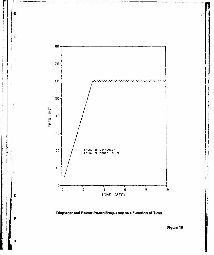
behavior, and the steady power characteristics. Figure 10 shows a plot of the
displacer and power pisioni frequency as a function of time. The starting procedure
was to linearly increase the displacer operating frequency trom 0 to 60 Hz over zi
three second period. The figure shows that the power piston closely follows the
displacer ]requericy up to the steady operating condition. There is a slight frequency
ripple which is damped. This ripple has an amplitude of about 1% of the 60 Hz steady
,d value initially, and then quickly damps out. This means that the voltage output fromr
the generator and harmonic content would be well within the military standards for
tactical power units. C
The ramp in frequency for starting will be p,'oduced by the microprocessor
controlier. Since the microprocessor is crystal controlled, the steady staýe frequency
of 60 Hz will be very prerise.
Figure I I shows the power output from the Stirling/Ringbom engine as a function
of tht phase angle between the displacer and the power piston. Maximrm power is
achieved F t a 90C phase angle. At the nominal engine power output of 3.8 kW (3kW
electrical output plus 0.8 kW for accessories) the operating phase angle is 470.
t ' " .. • • '•'•, •:' .•- •, • ..... .. ... . .. . . . ..... . '. • ...
70-
- - - - - - - --__ _ _- - - - - - -
440
0
LL
30
204 -- FREQ. OF DISFLRCERFM-- FREQ. (F r@ONER IRAIN
10-
0 2 4 6 8 10
TIME (SEC)
Displacer and Power Piston Frequency as a Function of Time
Figure 10

6. 0
5.0-
4.5- ID
4.0-
133.5-
3.0
•2.5 C3
2.05
1.0-
0. 5-{
0.0 , I , I ,
0 15 30 45 o75 90
OEG.
Pc'wr Output from the Stirling/Ringbom as a Function of Phase Angle
FFigure 11

Research and Technology DivisionArmy Stirling Pt.lgress ReportAugust 1982
-35-
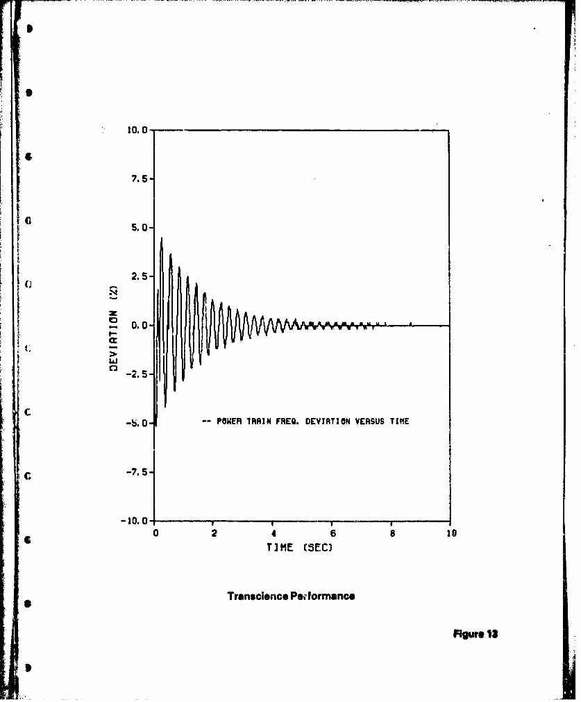
Transient performance data are presented as percent deviation of instantaneousfrequency from the steady frequency of 60 Hz. These results c&n be interpreted as a
percent voltage variation and also as a percent harmonic content. The oscillation has
a freq'ency of about 4 Hz. The damping is proportional to the applied load, as can be
seen by comparing Figures 12 and 13. Figure 14 shows the effect of load rejection.
I S The no-load condition was assumed to be 800 watts of power output from the
generator, used to power the combustor blower, fuel pump, cooling fan, battery
charger, controller and other auxiliaries.These results indicate that the system will easily meet the requirements for
tactical power generation.
6. CONCLUSIONS
The work presented in this study showed that a long life, maintenance-free
Stirling/Ringbom engine design could be built using current technology scaled up from
a heart pump power source. The design features a sealed power unit similar to a home
refrigerator compressor which would be protected from the environment and not
require a working fluid make-up system. The heater head employs a heat pipe to
eliminate the burn-out problems associated with prior designs. A two-phase coolingsystem eliminates the need for a coolant pump, a major source of repair problems.There are no high-pressure sliding seals in the design, which is the main reason that a
long, maintenance-free life is projected.
A microprocessor controller insures that the system is always operating at the
optimum efficiency and reduces the operator controls to a simple on/off switch. The
controller also provides diagnostics to help with field maintenance.
Computer simulations of the design showed that the crystal-based drive for the
system provides precise frequency control. The transient load performance of thesystem far exceeds the tactical generator requirements set forth in MIL-STD-1332B.
The results of this study clearly indicate that a Phase 2 hardware development
effort would be justified.I
1093R£
J
~6

10.0O
7.5
5.0 (
2.5-
0.0 I
-2.51
.5.0-- POWER TROIN FREQ. DEVIRTION VERSUS TIME C
-7. 5-
-10(-
0 2 4 6 8 10TI ME (SEC) C
Transcience Performance
Figure 12
"6i
[
7.5-
5.0
2.5
o•- 0.0
ow
C -2.5
-b.0 -- POWER TRRIN FREQ. DEVIATION VERSUS TIME
-7.5
-10.0 , , .. . .
0 2 4 6 810TIME (SEC)
Transcience Pei-dormance
Figre 13

10.0-
01
-7. 5-
50 0 8I
2.5 li
0.0 - ~~MAMcc I
-2.5-
-5.0-- POWER TRAIN FR'Q. DEVIATION VERSUS TIME
-7.5-
0 24 a to1
?1ME (SEC)
The Effect of Load Rejection
Fhge 14