Embed Size (px)
Citation preview
8/3/2019 R. A. Vesey et al- Target design for high fusion yield with the double Z-pinch-driven hohlraum
http://slidepdf.com/reader/full/r-a-vesey-et-al-target-design-for-high-fusion-yield-with-the-double-z-pinch-driven 1/13
Target design for high fusion yield with the doubleZ-pinch-driven hohlrauma…
R. A. Vesey,b M. C. Herrmann, R. W. Lemke, M. P. Desjarlais, M. E. Cuneo,W. A. Stygar, G. R. Bennett, R. B. Campbell, P. J. Christenson, T. A. Mehlhorn,J. L. Porter, and S. A. SlutzSandia National Laboratories, P.O. Box 5800, Albuquerque, New Mexico 87185-1186
Received 29 October 2006; accepted 11 January 2007; published online 22 March 2007
A key demonstration on the path to inertial fusion energy is the achievement of high fusion yield
hundreds of MJ and high target gain. Toward this goal, an indirect-drive high-yield inertial
confinement fusion ICF target involving two Z-pinch x-ray sources heating a central secondary
hohlraum is described by Hammer et al. Phys. Plasmas 6, 2129 1999. In subsequent research at
Sandia National Laboratories, theoretical/computational models have been developed and an
extensive series of validation experiments have been performed to study hohlraum energetics,
capsule coupling, and capsule implosion symmetry for this system. These models have been used to
design a high-yield Z-pinch-driven ICF target that incorporates the latest experience in capsule
design, hohlraum symmetry control, and x-ray production by Z pinches. An x-ray energy output of
9 MJ per pinch, suitably pulse-shaped, is sufficient for this concept to drive 0.3–0.5 GJ capsules.
For the first time, integrated two-dimensional 2D hohlraum/capsule radiation-hydrodynamics
simulations have demonstrated adequate hohlraum coupling, time-dependent radiation symmetry
control, and the successful implosion, ignition, and burn of a high-yield capsule in the doubleZ-pinch hohlraum. An important new feature of this target design is mode-selective symmetry
control: the use of burn-through shields offset from the capsule that selectively tune certain
low-order asymmetry modes P2 , P4 without significantly perturbing higher-order modes and
without a significant energy penalty. This paper will describe the capsule and hohlraum design that
have produced 0.4–0.5 GJ yields in 2D simulations, provide a preliminary estimate of the Z-pinch
load and accelerator requirements necessary to drive the system, and suggest future directions for
target design work. © 2007 American Institute of Physics. DOI: 10.1063/1.2472364
I. INTRODUCTION
Z pinches driven by fast pulsed-power 100 ns current
pulses are very efficient sources of soft x rays,
1
and theirpotential for indirect-drive inertial confinement fusion ICF
is currently being explored in a variety of approaches. One
approach is the high-yield concept proposed by Hammer et
al.,2
which uses a Z-pinch-driven primary hohlraum at each
end of a central coaxial secondary hohlraum containing the
ICF capsule. Figure 1 illustrates the features of the hohlraum
geometry relevant for this hohlraum concept. This vacuum
hohlraum-based concept has been developed as an experi-
mental platform on the Z accelerator3
at Sandia National
Laboratories. This platform has provided high quality data to
validate the numerical simulations of this concept. Experi-
ments conducted over the past several years have quantified
the Z-pinch power, primary hohlraum radiation temperatures,and primary-secondary hohlraum coupling efficiency for
configurations relevant to this concept.4–7
Viewfactor and
radiation-hydrodynamics models have been used to design
hohlraums that tune the capsule radiation symmetry for near-
term experiments.8,9
An advanced double Z-pinch wire-array
load driven by a single power feed has been developed that
provides upper and lower pinch x-ray power histories that
are balanced such that measurements of upper and lower
primary hohlraum wall emission temperatures agree within
instrumental error bars.10
For symmetry diagnosis, the
Z-Beamlet Laser11 is being used to create high-energy x raysfor point projection backlighting
12and bent-crystal
imaging13
of capsule implosions in double Z-pinch hohl-
raums. Backlit capsule images on Z have enabled measure-
ments of implosion trajectories as well as in-flight distortions
at the percent level12
for the first time in Z-pinch-driven
hohlraums, and a hohlraum length scan demonstrated that
pole-to-equator radiation asymmetry can be predictably ze-
roed as a function of secondary hohlraum geometry.14,15
Sev-
eral years of validation experiments16,17
provide confidence
in the modeling capability that will now be applied to updat-
ing the high-yield target design. A review of eight years of
experiments and simulations on the double Z-pinch platformhas been published recently.18
The initial scoping study of the double Z-pinch hohl-
raum by Hammer et al.2
identified many key physics issues,
quantified the energetics of such a system, and provided the
starting point for the present study. The previous study used
a circuit model of the Z accelerator, with the open-circuit
voltage scaled up, to drive two-dimensional 2D simulations
of Z-pinch performance. At peak currents of 63 MA, a mul-
tishell Z pinch composed of low-Z materials lithium deu-
teride was calculated to provide a useful x-ray pulse shape
aPaper BI2 2, Bull. Am. Phys. Soc. 51, 23 2006.
bInvited speaker.
PHYSICS OF PLASMAS 14, 056302 2007
1070-664X/2007/145 /056302/13/$23.00 © 2007 American Institute of Physic14, 056302-1
Downloaded 26 Mar 2007 to 134.253.26.11. Redistribution subject to AIP license or copyright, see http://pop.aip.org/pop/copyright.jsp
8/3/2019 R. A. Vesey et al- Target design for high fusion yield with the double Z-pinch-driven hohlraum
http://slidepdf.com/reader/full/r-a-vesey-et-al-target-design-for-high-fusion-yield-with-the-double-z-pinch-driven 2/13
with peak powers of order 1000 TW and total x-ray energy
outputs of 8–10 MJ per pinch depending on assumed per-
turbation levels. Using the calculated Z-pinch output as in-
put to 2D hohlraum calculations, shaped capsule drive tem-
perature pulses with peak temperatures of 210 eV were
obtained. The time-dependent behavior of the radial spoke
arrays that separate the primary and secondary hohlraums
was calculated to provide adequate hohlraum coupling while
confining the magnetic field to the primary hohlraum, and
the sensitivity of the hohlraum energetics to the effective
spoke transmission was quantified. Finally, a high-yield cap-
sule was found to be compatible with the calculated drive
pulse; the capsule absorbs 1 MJ of x rays with a fusion yield
of 400 MJ. This scoping study highlighted the crucial issues
for this high-yield target concept that have been the objects
of subsequent experimental study on Z and that are the ob-
jects of the present design study: Z-pinch x-ray pulse shap-
ing, hohlraum energetics and coupling, radiation symmetry
control, and capsule robustness. The main new result pre-
sented in this paper is the development of a complete strat-
egy for radiation symmetry control that allows for robust
capsule ignition and burn in 2D hohlraum simulations, a nec-essary achievement for any modern ICF target design.
II. HIGH-YIELD CAPSULE DESIGN
A. Characteristics and one-dimensional performance
The original double Z-pinch hohlraum reference2
de-
scribed a 400 MJ yield capsule with a beryllium ablator to be
driven by a pulse with a peak radiation temperature
210 eV. The capsule chosen for the present design is simi-
lar to the earlier capsule. The main fuel is a cryogenic
deuterium-tritium DT layer deposited on the inside of the
spherical ablator shell. The ablator is composed of beryllium,
doped uniformly with 0.2 at. % of copper to mitigate preheat
of the DT fuel by the higher energy photons in the tail of a
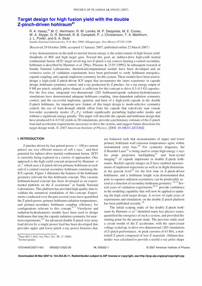
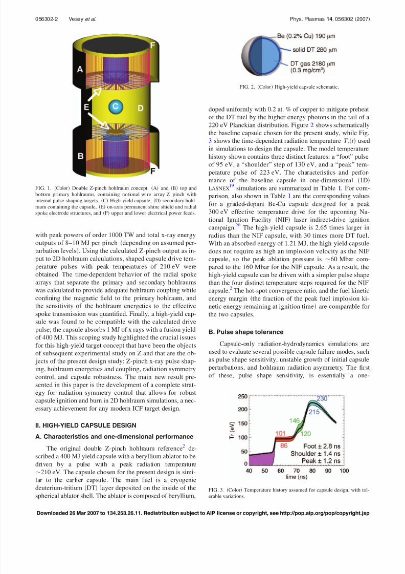
220 eV Planckian distribution. Figure 2 shows schematically
the baseline capsule chosen for the present study, while Fig.
3 shows the time-dependent radiation temperature T r t used
in simulations to design the capsule. The model temperature
history shown contains three distinct features: a “foot” pulse
of 95 eV, a “shoulder” step of 130 eV, and a “peak” tem-
perature pulse of 223 eV. The characteristics and perfor-
mance of the baseline capsule in one-dimensional 1D
LASNEX19
simulations are summarized in Table I. For com-
parison, also shown in Table I are the corresponding values
for a graded-dopant Be-Cu capsule designed for a peak
300 eV effective temperature drive for the upcoming Na-
tional Ignition Facility NIF laser indirect-drive ignition
campaign.20
The high-yield capsule is 2.65 times larger in
radius than the NIF capsule, with 30 times more DT fuel.
With an absorbed energy of 1.21 MJ, the high-yield capsule
does not require as high an implosion velocity as the NIF
capsule, so the peak ablation pressure is 60 Mbar com-
pared to the 160 Mbar for the NIF capsule. As a result, the
high-yield capsule can be driven with a simpler pulse shape
than the four distinct temperature steps required for the NIF
capsule.2
The hot-spot convergence ratio, and the fuel kinetic
energy margin the fraction of the peak fuel implosion ki-netic energy remaining at ignition time are comparable for
the two capsules.
B. Pulse shape tolerance
Capsule-only radiation-hydrodynamics simulations are
used to evaluate several possible capsule failure modes, such
as pulse shape sensitivity, unstable growth of initial capsule
perturbations, and hohlraum radiation asymmetry. The first
of these, pulse shape sensitivity, is essentially a one-
FIG. 3. Color Temperature history assumed for capsule design, with tol-
erable variations.
FIG. 1. Color Double Z-pinch hohlraum concept. A and B top and
bottom primary hohlraums, containing notional wire array Z pinch with
internal pulse-shaping targets. C High-yield capsule, D secondary hohl-raum containing the capsule, E on-axis permanent shine shield and radial
spoke electrode structures, and F upper and lower electrical power feeds.
FIG. 2. Color High-yield capsule schematic.
056302-2 Vesey et al. Phys. Plasmas 14, 056302 2007
Downloaded 26 Mar 2007 to 134.253.26.11. Redistribution subject to AIP license or copyright, see http://pop.aip.org/pop/copyright.jsp
8/3/2019 R. A. Vesey et al- Target design for high fusion yield with the double Z-pinch-driven hohlraum
http://slidepdf.com/reader/full/r-a-vesey-et-al-target-design-for-high-fusion-yield-with-the-double-z-pinch-driven 3/13
dimensional failure mode. The values of DT fuel in-flight
minimum adiabat if , and the mass fraction of the DT fuel on
a high adiabat 1.5 if shown in Table I, indicate that the
model T r t pulse maintains the fuel at low entropy during
the implosion, resulting in high peak fuel density and areal
density, which provide efficient fusion burn. The fuel adia-
bat is defined as P / 2.18 5/3 where P is the pressure in
Mbar and is the density in g/cc.21
As Fig. 3 illustrates, the
baseline capsule can tolerate relatively large deviations away
from the model temperature history and still give nearly full
yield, corresponding to factors of 1.9, 2.2, and 1.3 full ranges
in the incident radiation flux in the foot, shoulder, and peak
pulse, respectively. The radiation prior to the foot is gener-
ated during the pinch implosion by ohmic heating of the Zpinch and is not necessary for good capsule performance. In
fact, this run-in radiation may lead to early time imprinting
of radiation asymmetries, growth of surface perturbations
without significant ablative stabilization, and imprinting of
beryllium microstructure variations prior to the multi-Mbar
foot shock passing through the ablator. If necessary, tamping
foams at the secondary hohlraum entrance can be designed to
absorb essentially all of the run-in radiation to prevent it
from affecting the capsule implosion. Note that the T r varia-
tions shown in Fig. 3 are single-feature variations; for ex-
ample, the foot temperature can vary within the
86 to 101 eV range as long as the remainder of the pulse
follows the baseline T r t history. Likewise, the timing of thefoot, shoulder, and peak pulses can vary by ±2.8, 1.4, and
1.2 ns, respectively, without degrading the capsule yield. The
maximum and minimum allowable timing variations are de-
termined by the need to prevent successive shocks from coa-
lescing inside the DT ice layer and to limit the amount of
fuel rarefaction that occurs after a shock breaks out from the
inner surface of the DT ice.21
C. Capsule surface perturbation tolerance
Initial perturbations on surfaces and material interfaces
within the capsule will grow during the capsule acceleration
and deceleration due to the Rayleigh-Taylor RT instability.
Excessive growth of perturbations will cause degradation of
the fusion burn and, with large enough perturbations, failure
of the capsule to ignite by degrading the final compression
phase which forms the hot spot. Two-dimensional 2D LAS-
NEX radiation-hydrodynamics simulations model the effects
of RT instability by studying the growth from a full spectrum
of modes typical of fabricated ablator shells.22–25
The pre-
liminary multimode calculations described here use the same
methodology used previously for ignition capsules.22,23,25
A
15° wedge of the capsule near the equator is modeled which
allows for one-half wavelength of mode 12, while the angu-
lar resolution for practical calculations is chosen to resolve
up to mode 160. An inline equation of state26
is used, and
another key feature is the collapsed-group opacity scheme of Marinak et al.,27
which enables accurate calculations with
relatively few photon energy groups for these problems. Fig-
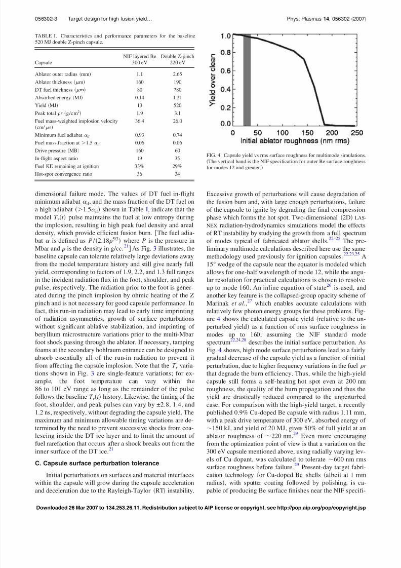
ure 4 shows the calculated capsule yield relative to the un-
perturbed yield as a function of rms surface roughness in
modes up to 160, assuming the NIF standard mode
spectrum22,24,28
describes the initial surface perturbation. As
Fig. 4 shows, high mode surface perturbations lead to a fairly
gradual decrease of the capsule yield as a function of initial
perturbation, due to higher frequency variations in the fuel r
that degrade the burn efficiency. Thus, while the high-yield
capsule still forms a self-heating hot spot even at 200 nm
roughness, the quality of the burn propagation and thus the
yield are drastically reduced compared to the unperturbedcase. For comparison with the high-yield target, a recently
published 0.9% Cu-doped Be capsule with radius 1.11 mm,
with a peak drive temperature of 300 eV, absorbed energy of
150 kJ, and yield of 20 MJ, gives 50% of full yield at an
ablator roughness of 220 nm.29
Even more encouraging
from the optimization point of view is that a variation on the
300 eV capsule mentioned above, using radially varying lev-
els of Cu dopant, was calculated to tolerate 600 nm rms
surface roughness before failure.29
Present-day target fabri-
cation technology for Cu-doped Be shells albeit at 1 mm
radius, with sputter coating followed by polishing, is ca-
pable of producing Be surface finishes near the NIF specifi-
TABLE I. Characteristics and performance parameters for the baseline
520 MJ double Z-pinch capsule.
Capsule
NIF layered Be
300 eV
Double Z-pinch
220 eV
Ablator outer radius mm 1.1 2.65
Ablator thickness m 160 190
DT fuel thickness m 80 280
Absorbed energy MJ 0.14 1.21Yield MJ 13 520
Peak total r g/cm2 1.9 3.1
Fuel mass-weighted implosion velocity
cm/ s
36.4 26.0
Minimum fuel adiabat if 0.93 0.74
Fuel mass fraction at 1.5 if 0.06 0.06
Drive pressure MB 160 60
In-flight aspect ratio 19 35
Fuel KE remaining at ignition 33% 29%
Hot-spot convergence ratio 36 34
FIG. 4. Capsule yield vs rms surface roughness for multimode simulations.
The vertical band is the NIF specification for outer Be surface roughness
for modes 12 and greater.
056302-3 Target design for high fusion yield… Phys. Plasmas 14, 056302 2007
Downloaded 26 Mar 2007 to 134.253.26.11. Redistribution subject to AIP license or copyright, see http://pop.aip.org/pop/copyright.jsp
8/3/2019 R. A. Vesey et al- Target design for high fusion yield with the double Z-pinch-driven hohlraum
http://slidepdf.com/reader/full/r-a-vesey-et-al-target-design-for-high-fusion-yield-with-the-double-z-pinch-driven 4/13
cation of 36 nm for modes 12 and greater,30 a factor of 4
below the point at which the high-yield capsule fails.
D. Radiation asymmetry tolerance
A perfectly spherical capsule will undergo an aspherical
implosion if the radiation field driving it is spatially nonuni-
form. Although a hohlraum naturally smooths the x-ray dis-
tribution within it, ignition capsules require a very high de-
gree of x-ray symmetry in order to remain nearly spherical to
radial convergence ratios of 30 or greater. A series of
capsule-only 2D LASNEX simulations identify, for each
mode, the Legendre mode coefficient of the flux asymmetryconstant in time over the entire drive pulse that causes the
capsule fusion yield to be degraded by 50% compared to the
uniform-drive case. Unlike the short-wavelength perturba-
tions described in the previous section, long-wavelength ra-
diation asymmetry does not significantly degrade the burn
propagation of an igniting capsule, but rather at high enough
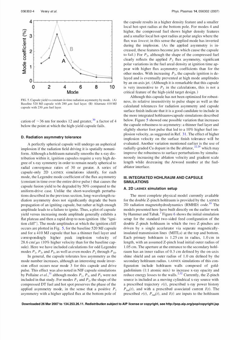
amplitude leads to a failure to ignite. Thus, a plot of capsule
yield versus increasing mode amplitude generally exhibits a
flat plateau and then a rapid drop to non-ignition the “igni-
tion cliff”. The mode amplitudes at which the ignition cliff
occurs are plotted in Fig. 5, for the baseline 520 MJ capsule
and for a 410 MJ capsule that has a thinner fuel layer and
correspondingly higher peak implosion velocity of 28.6 cm/ s 10% higher velocity than for the baseline cap-
sule. Here we have included calculations for odd Legendre
modes P1, P3, and P5, as well as even modes P2 through P10.
In general, the capsule tolerates less asymmetry as the
mode number increases, although an interesting mode inver-
sion effect occurs near mode 3 for this capsule and drive
pulse. This effect was also noted in NIF capsule simulations
by Pollaine et al.,31
although modes P1, P3, and P5 were not
included in that study. For modes P1 and P2, the shape of the
compressed DT fuel and hot spot preserves the phase of the
applied asymmetry mode, in the sense that a positive P1
asymmetry with a higher applied flux at the bottom pole of
the capsule results in a higher density feature and a smaller
local hot-spot radius at the bottom pole. For modes 4 and
higher, the compressed fuel shows higher density features
and a smaller local hot-spot radius at polar angles where the
flux was lowest ; in this sense the applied mode has inverted
during the implosion. As the applied asymmetry is in-
creased, these features become jets which cause the capsule
to fail. For P3, although the shape of the compressed fuel
clearly reflects the applied P3 flux asymmetry, significantpolar variations in the fuel areal density at ignition time ap-
pear with higher flux asymmetry coefficients than for the
other modes. With increasing P3, the capsule ignition is de-
layed and is eventually prevented at high mode amplitudes
by an on-axis jet. Although it is remarkable that this capsule
is very insensitive to P3 in the calculations, this is not a
critical feature of the high-yield target design.
Although this capsule has not been optimized for robust-
ness, its relative insensitivity to pulse shape as well as the
calculated tolerances for radiation asymmetry and capsule
surface finish indicate that it is a good candidate to include in
the more integrated hohlraum+capsule simulations described
below. Figure 5 showed one possible variation that increasesthe capsule robustness to asymmetry: a thinner fuel layer and
slightly shorter foot pulse that led to a 10% higher fuel im-
plosion velocity, as suggested in Ref. 31. The effect of higher
implosion velocity on the surface finish tolerance will be
evaluated. Another variation mentioned earlier is the use of
radially-graded Cu dopant in the Be ablator,22,29
which may
improve the robustness to surface perturbations by simulta-
neously increasing the ablation velocity and gradient scale
length while decreasing the Atwood number at the fuel-
ablator interface.
III. INTEGRATED HOHLRAUM AND CAPSULESIMULATIONS
A. 2D LASNEX simulation setup
The most complete physical model currently available
for the double Z-pinch hohlraum is provided by the LASNEX
2D radiation magnetohydrodynamics RMHD code.19
The
models presented here have built directly on the earlier work
by Hammer and Tabak.2
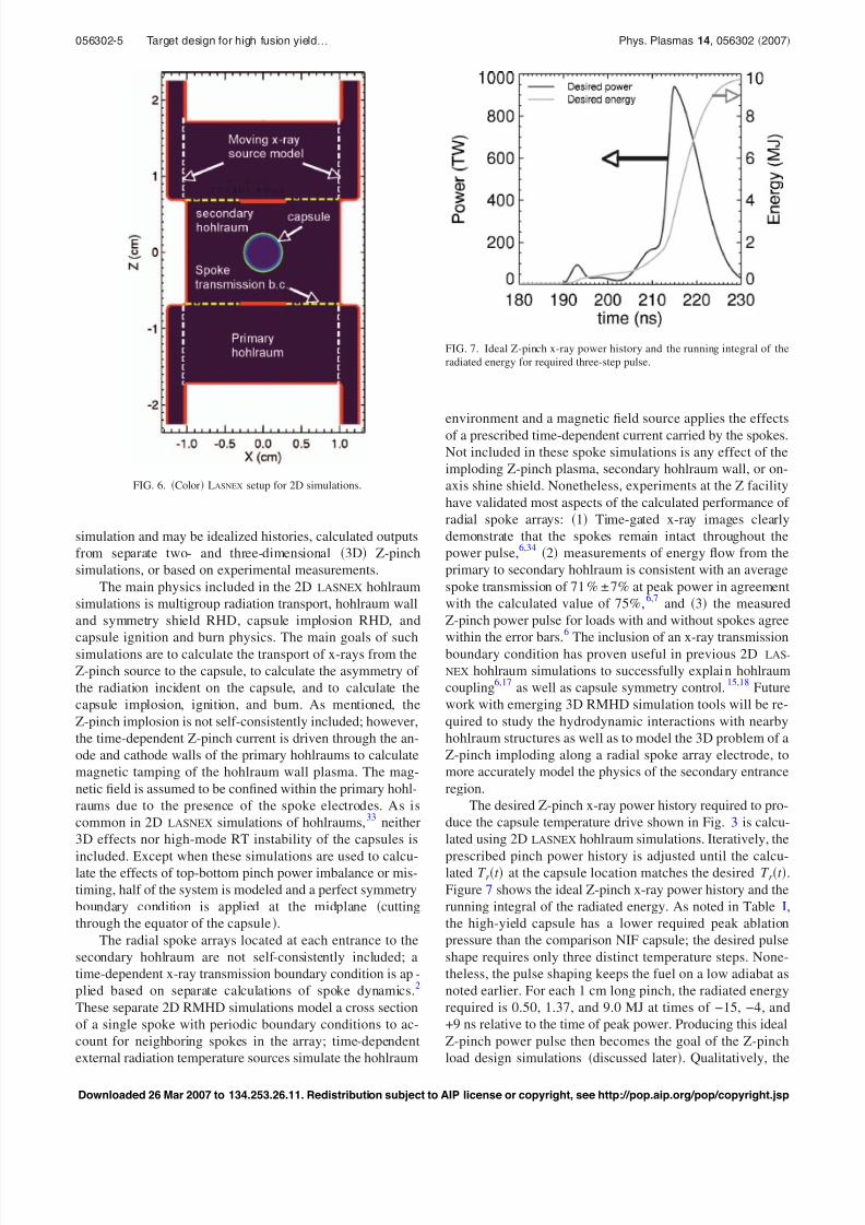
Figure 6 shows the initial simulation
setup for the standard two-sided feed configuration of the
double Z-pinch hohlraum in which the two Z-pinches are
driven by a single accelerator via separate magnetically-
insulated transmission lines MITLs at the top and bottom.
Each primary hohlraum is 1.25 cm in radius, 1.0 cm inlength, with an assumed Z-pinch load initial outer radius of
1.05 cm. The aperture at the entrance to the secondary hohl-
raum has an inner radius of 0.3 cm defined by the on-axis
shine shield and an outer radius of 1.0 cm defined by the
secondary hohlraum radius. LASNEX simulations of this con-
figuration include hohlraum walls composed of gold-
gadolinium 1:1 atomic mix to increase x-ray opacity and
reduce energy losses to the walls.2,32
Currently, the Z-pinch
source is included as a moving cylindrical x-ray source with
a prescribed trajectory r t , prescribed x-ray power history
Pradt , and with a prescribed associated current I t . The
prescribed r t , Pradt , and I t are inputs to the hohlraum
FIG. 5. Capsule yield vs constant-in-time radiation asymmetry by mode. A
Baseline 520 MJ capsule with 280 m fuel layer. B Alternate 410 MJ
capsule with 230 m fuel layer.
056302-4 Vesey et al. Phys. Plasmas 14, 056302 2007
Downloaded 26 Mar 2007 to 134.253.26.11. Redistribution subject to AIP license or copyright, see http://pop.aip.org/pop/copyright.jsp
8/3/2019 R. A. Vesey et al- Target design for high fusion yield with the double Z-pinch-driven hohlraum
http://slidepdf.com/reader/full/r-a-vesey-et-al-target-design-for-high-fusion-yield-with-the-double-z-pinch-driven 5/13
simulation and may be idealized histories, calculated outputs
from separate two- and three-dimensional 3D Z-pinch
simulations, or based on experimental measurements.
The main physics included in the 2D LASNEX hohlraum
simulations is multigroup radiation transport, hohlraum wall
and symmetry shield RHD, capsule implosion RHD, and
capsule ignition and burn physics. The main goals of suchsimulations are to calculate the transport of x-rays from the
Z-pinch source to the capsule, to calculate the asymmetry of
the radiation incident on the capsule, and to calculate the
capsule implosion, ignition, and burn. As mentioned, the
Z-pinch implosion is not self-consistently included; however,
the time-dependent Z-pinch current is driven through the an-
ode and cathode walls of the primary hohlraums to calculate
magnetic tamping of the hohlraum wall plasma. The mag-
netic field is assumed to be confined within the primary hohl-
raums due to the presence of the spoke electrodes. As is
common in 2D LASNEX simulations of hohlraums,33
neither
3D effects nor high-mode RT instability of the capsules is
included. Except when these simulations are used to calcu-late the effects of top-bottom pinch power imbalance or mis-
timing, half of the system is modeled and a perfect symmetry
boundary condition is applied at the midplane cutting
through the equator of the capsule.
The radial spoke arrays located at each entrance to the
secondary hohlraum are not self-consistently included; a
time-dependent x-ray transmission boundary condition is ap-
plied based on separate calculations of spoke dynamics.2
These separate 2D RMHD simulations model a cross section
of a single spoke with periodic boundary conditions to ac-
count for neighboring spokes in the array; time-dependent
external radiation temperature sources simulate the hohlraum
environment and a magnetic field source applies the effects
of a prescribed time-dependent current carried by the spokes.
Not included in these spoke simulations is any effect of the
imploding Z-pinch plasma, secondary hohlraum wall, or on-
axis shine shield. Nonetheless, experiments at the Z facility
have validated most aspects of the calculated performance of
radial spoke arrays: 1 Time-gated x-ray images clearly
demonstrate that the spokes remain intact throughout the
power pulse,6,34
2 measurements of energy flow from the
primary to secondary hohlraum is consistent with an average
spoke transmission of 71 % ± 7% at peak power in agreement
with the calculated value of 75%,6,7
and 3 the measured
Z-pinch power pulse f or loads with and without spokes agree
within the error bars.
6
The inclusion of an x-ray transmissionboundary condition has proven useful in previous 2D LAS-
NEX hohlraum simulations to successfully explain hohlraum
coupling6,17
as well as capsule symmetry control.15,18
Future
work with emerging 3D RMHD simulation tools will be re-
quired to study the hydrodynamic interactions with nearby
hohlraum structures as well as to model the 3D problem of a
Z-pinch imploding along a radial spoke array electrode, to
more accurately model the physics of the secondary entrance
region.
The desired Z-pinch x-ray power history required to pro-
duce the capsule temperature drive shown in Fig. 3 is calcu-
lated using 2D LASNEX hohlraum simulations. Iteratively, the
prescribed pinch power history is adjusted until the calcu-lated T r t at the capsule location matches the desired T r t .
Figure 7 shows the ideal Z-pinch x-ray power history and the
running integral of the radiated energy. As noted in Table I,
the high-yield capsule has a lower required peak ablation
pressure than the comparison NIF capsule; the desired pulse
shape requires only three distinct temperature steps. None-
theless, the pulse shaping keeps the fuel on a low adiabat as
noted earlier. For each 1 cm long pinch, the radiated energy
required is 0.50, 1.37, and 9.0 MJ at times of −15, −4, and
+9 ns relative to the time of peak power. Producing this ideal
Z-pinch power pulse then becomes the goal of the Z-pinch
load design simulations discussed later. Qualitatively, the
FIG. 6. Color LASNEX setup for 2D simulations.
FIG. 7. Ideal Z-pinch x-ray power history and the running integral of the
radiated energy for required three-step pulse.
056302-5 Target design for high fusion yield… Phys. Plasmas 14, 056302 2007
Downloaded 26 Mar 2007 to 134.253.26.11. Redistribution subject to AIP license or copyright, see http://pop.aip.org/pop/copyright.jsp
8/3/2019 R. A. Vesey et al- Target design for high fusion yield with the double Z-pinch-driven hohlraum
http://slidepdf.com/reader/full/r-a-vesey-et-al-target-design-for-high-fusion-yield-with-the-double-z-pinch-driven 6/13
ideal power pulse is similar to the results shown by Hammer2
in terms of peak-to-foot power contrast and timing. Because
it satisfies the energy requirements of the capsule, this ideal
pulse will be used as input to the hohlraum+capsule simula-
tions to study time-dependent symmetry control.
B. Radiation symmetry control strategy
Without additional symmetry control structures in the
double Z-pinch hohlraum shown in Fig. 6, the radiation in-
cident on the capsule is quite symmetric, owing to the large
ratio of the wall surface area to the capsule surface area. As
has been discussed previously,7
about 70% of the radiation
entering the secondary hohlraum is due to primary hohlraum
wall re-emission, one level of spectral and spatial smoothing.
Of the radiation incident on the capsule, 75%–80% is due to
secondary hohlraum wall re-emission and 20%–25% is dueto primary hohlraum wall emission.15
Because of the on-
axis shine shield, ideally none of the Z-pinch radiation at
stagnation directly illuminates the capsule. The combination
of re-emission smoothing within the hohlraum and geometric
averaging at the capsule35
results in a fairly symmetric x-ray
flux distribution on the capsule. LASNEX simulations of the
hohlraum+capsule configuration of Fig. 6 show low time-
averaged radiation asymmetry, as evidenced by the polar
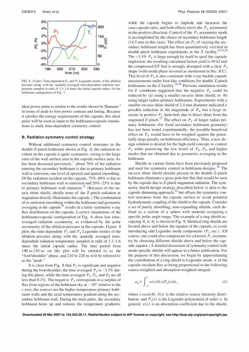
asymmetry of the ablation pressure in the capsule. Figure 8
plots the time-dependent P2 and P4 Legendre modes of the
ablation pressure along with the spatially averaged time-
dependent radiation temperature sampled at radii of 1.3–1.6
times the initial capsule radius. The time period from190 to 210 ns on this plot will be referred to as the
“foot/shoulder” phase, and 210 to 220 ns will be referred to
as the “peak.”
It is clear from Fig. 8 that P4 is significant and negative
during the foot/shoulder; the time-averaged P4 is −3.3% dur-
ing this phase, while the time-averaged P2, P6, and P8 are all
less than 0.2%. The negative P4 corresponds to a surplus of
flux from regions of the hohlraum sky at 45° relative to the
z axis; the sources are the higher temperature primary hohl-
raum walls and the axial temperature gradient along the sec-
ondary hohlraum wall. During the main pulse, the secondary
hohlraum heats up and reduces the temperature gradients,
while the capsule begins to implode and increases the
case:capsule ratio, and both effects move the P4 asymmetry
in the positive direction. Control of the P2 asymmetry mode
is accomplished by the choice of secondary hohlraum length
14.5 mm in this case. The effect on P2 of varying the sec-
ondary hohlraum length has been quantitatively verified in
double-pinch hohlraum experiments at the Z facility.14,15,18
The −3.3% P4 is large enough by itself to spoil the capsule
implosion; the resulting calculated fusion yield is 40 kJ andthe compressed DT fuel is strongly disrupted with a clear P4
shape with mode phase inverted as mentioned in Sec. II C.
This level of P4 is also consistent with x-ray backlit capsule
measurements under foot-like conditions for double Z-pinch
hohlraums on the Z facility.18,36
Previous simulation results
for Z conditions suggested that the negative P4 could be
reduced by a using a smaller on-axis shine shield, or b
using larger radius primary hohlraums. Experiments with a
smaller on-axis shine shield of 2.4 mm diameter indicated a
possible reduction in the magnitude of P4, but a large in-
crease in positive P2 pole-hot due to direct shine from the
stagnated Z pinch.37
The effect on P4 of larger radius pri-
mary hohlraums for fixed secondary hohlraum geometryhas not been tested experimentally; the possible beneficial
effect on P4 would have to be weighed against the poten-
tially large penalty on hohlraum efficiency. Thus, a new de-
sign solution is desired for the high-yield concept, to control
P4 while preserving the low levels of P6, P8, and higher
modes that are obtained due to geometric averaging in the
hohlraum.
Shields in various forms have been previously proposed
and used for symmetry control in hohlraum designs.38
The
on-axis shine shield already present in the double Z-pinch
hohlraum eliminates a gross pole-hot flux that would be seen
by the capsule due to Z-pinch stagnation radiation. The sym-
metry shield design strategy described below is akin to the
capsule shimming approach,39
but offsets the symmetry con-
trol structures from the capsule surface to avoid potential
hydrodynamic coupling of the shield to the capsule. Consider
a set of purely absorbing, non-expanding shields, each de-
fined as a section of a sphere with material occupying a
specific polar angle range. The example of a ring shield oc-
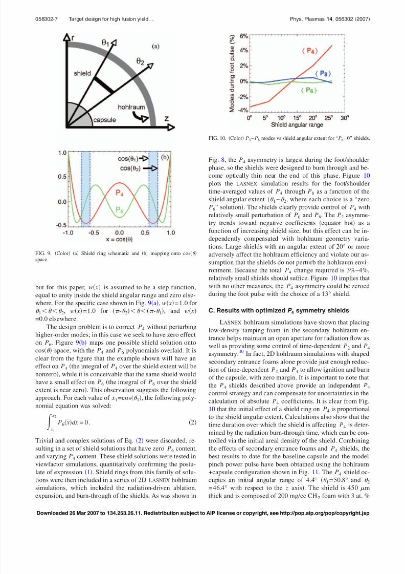
cupying 1 to 2 is shown in Fig. 9. Identical ring shields are
located above and below the equator of the capsule, to avoid
introducing odd Legendre mode components P1, etc.. Of
course, one could also compensate for a known P1 asymme-
try by choosing different shields above and below the cap-
sule equator. A detailed discussion of symmetry control withmode-specific shields will appear in a future publication. For
the purpose of this discussion, we begin by approximating
the contribution of a ring shield to Legendre mode n of the
capsule-incident flux as being proportional to the following
source-weighted and absorption-weighted integral:
an −1
1
w xS xPn xdx , 1
where x =cos , S x is the relative source intensity distri-
bution, and Pn x is the Legendre polynomial of order n. In
general, w x is an absorption coefficient due to the shield,
FIG. 8. Color Time-dependent P2 and P4 Legendre modes of the ablation
pressure along with the spatially averaged time-dependent radiation tem-
perature sampled at radii of 1.3–1.6 times the initial capsule radius, for the
hohlraum configuration of Fig. 7.
056302-6 Vesey et al. Phys. Plasmas 14, 056302 2007
Downloaded 26 Mar 2007 to 134.253.26.11. Redistribution subject to AIP license or copyright, see http://pop.aip.org/pop/copyright.jsp
8/3/2019 R. A. Vesey et al- Target design for high fusion yield with the double Z-pinch-driven hohlraum
http://slidepdf.com/reader/full/r-a-vesey-et-al-target-design-for-high-fusion-yield-with-the-double-z-pinch-driven 7/13
but for this paper, w x is assumed to be a step function,
equal to unity inside the shield angular range and zero else-
where. For the specific case shown in Fig. 9a, w x = 1.0 for 1 2, w x =1.0 for - 2 - 1, and w x
=0.0 elsewhere.
The design problem is to correct P4 without perturbing
higher-order modes; in this case we seek to have zero effect
on P6. Figure 9b maps one possible shield solution onto
cos space, with the P4 and P6 polynomials overlaid. It is
clear from the figure that the example shown will have an
effect on P4 the integral of P4 over the shield extent will be
nonzero, while it is conceivable that the same shield would
have a small effect on P6 the integral of P6 over the shield
extent is near zero. This observation suggests the following
approach. For each value of x1 =cos 1, the following poly-
nomial equation was solved:
x1
x2
P6 xdx = 0 . 2
Trivial and complex solutions of Eq. 2 were discarded, re-
sulting in a set of shield solutions that have zero P6 content,
and varying P4 content. These shield solutions were tested in
viewfactor simulations, quantitatively confirming the postu-
late of expression 1. Shield rings from this family of solu-
tions were then included in a series of 2D LASNEX hohlraum
simulations, which included the radiation-driven ablation,
expansion, and burn-through of the shields. As was shown in
Fig. 8, the P4 asymmetry is largest during the foot/shoulder
phase, so the shields were designed to burn through and be-
come optically thin near the end of this phase. Figure 10
plots the LASNEX simulation results for the foot/shoulder
time-averaged values of P4 through P8 as a function of the
shield angular extent 1− 2, where each choice is a “zero
P6” solution. The shields clearly provide control of P4 with
relatively small perturbation of P6 and P8. The P2 asymme-
try trends toward negative coefficients equator hot as a
function of increasing shield size, but this effect can be in-
dependently compensated with hohlraum geometry varia-
tions. Large shields with an angular extent of 20° or more
adversely affect the hohlraum efficiency and violate our as-
sumption that the shields do not perturb the hohlraum envi-
ronment. Because the total P4 change required is 3%–4%,
relatively small shields should suffice. Figure 10 implies that
with no other measures, the P4 asymmetry could be zeroed
during the foot pulse with the choice of a 13° shield.
C. Results with optimized P 4 symmetry shields
LASNEX hohlraum simulations have shown that placing
low-density tamping foam in the secondary hohlraum en-
trance helps maintain an open aperture for radiation flow as
well as providing some control of time-dependent P2 and P4
asymmetry.40
In fact, 2D hohlraum simulations with shaped
secondary entrance foams alone provide just enough reduc-
tion of time-dependent P2 and P4 to allow ignition and burn
of the capsule, with zero margin. It is important to note that
the P4 shields described above provide an independent P4
control strategy and can compensate for uncertainties in the
calculation of absolute P4 coefficients. It is clear from Fig.10 that the initial effect of a shield ring on P4 is proportional
to the shield angular extent. Calculations also show that the
time duration over which the shield is affecting P4 is deter-
mined by the radiation burn-through time, which can be con-
trolled via the initial areal density of the shield. Combining
the effects of secondary entrance foams and P4 shields, the
best results to date for the baseline capsule and the model
pinch power pulse have been obtained using the hohlraum
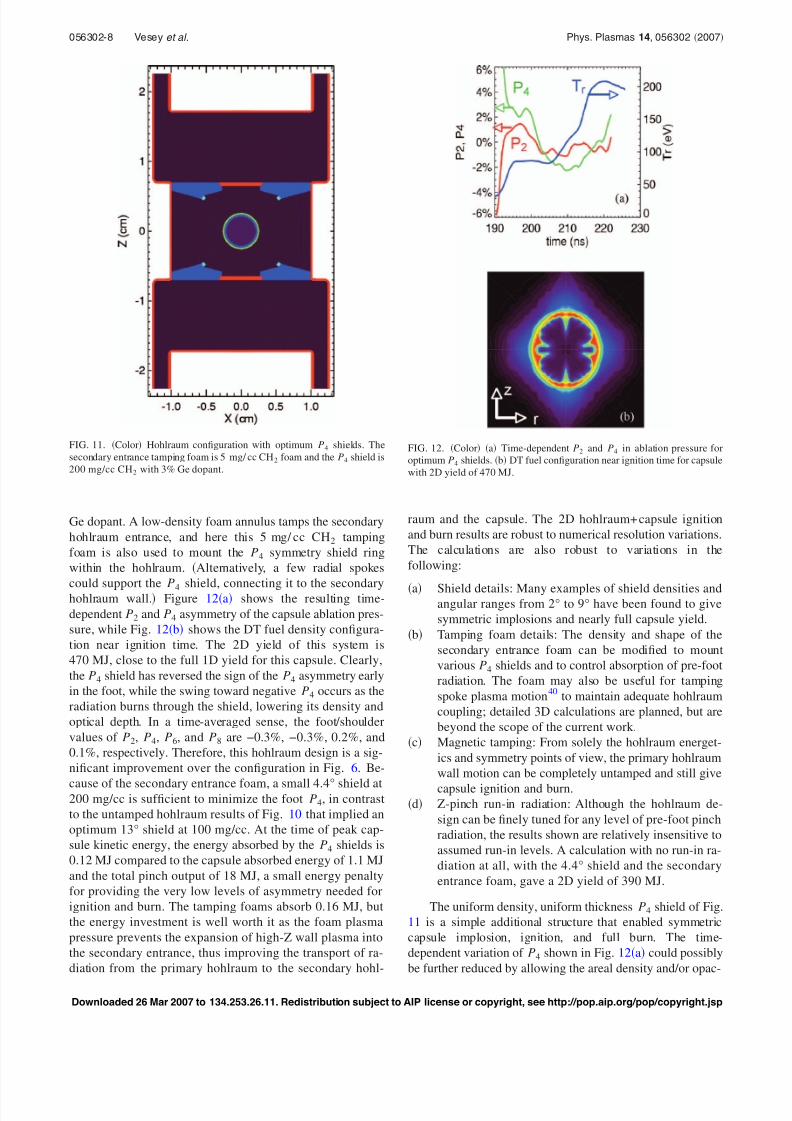
+capsule configuration shown in Fig. 11. The P4 shield oc-
cupies an initial angular range of 4.4° 1 = 50.8° and 2= 46.4° with respect to the z axis. The shield is 450 m
thick and is composed of 200 mg/cc CH2 foam with 3 at. %
FIG. 9. Color a Shield ring schematic and b mapping onto cos
space.
FIG. 10. Color P4 – P8 modes vs shield angular extent for “P6 =0” shields.
056302-7 Target design for high fusion yield… Phys. Plasmas 14, 056302 2007
Downloaded 26 Mar 2007 to 134.253.26.11. Redistribution subject to AIP license or copyright, see http://pop.aip.org/pop/copyright.jsp
8/3/2019 R. A. Vesey et al- Target design for high fusion yield with the double Z-pinch-driven hohlraum
http://slidepdf.com/reader/full/r-a-vesey-et-al-target-design-for-high-fusion-yield-with-the-double-z-pinch-driven 8/13
Ge dopant. A low-density foam annulus tamps the secondary
hohlraum entrance, and here this 5 mg/ cc CH2 tamping
foam is also used to mount the P4 symmetry shield ring
within the hohlraum. Alternatively, a few radial spokes
could support the P4 shield, connecting it to the secondaryhohlraum wall. Figure 12a shows the resulting time-
dependent P2 and P4 asymmetry of the capsule ablation pres-
sure, while Fig. 12b shows the DT fuel density configura-
tion near ignition time. The 2D yield of this system is
470 MJ, close to the full 1D yield for this capsule. Clearly,
the P4 shield has reversed the sign of the P4 asymmetry early
in the foot, while the swing toward negative P4 occurs as the
radiation burns through the shield, lowering its density and
optical depth. In a time-averaged sense, the foot/shoulder
values of P2, P4, P6, and P8 are −0.3%, −0.3%, 0.2%, and
0.1%, respectively. Therefore, this hohlraum design is a sig-
nificant improvement over the configuration in Fig. 6. Be-
cause of the secondary entrance foam, a small 4.4° shield at200 mg/cc is sufficient to minimize the foot P4, in contrast
to the untamped hohlraum results of Fig. 10 that implied an
optimum 13° shield at 100 mg/cc. At the time of peak cap-
sule kinetic energy, the energy absorbed by the P4 shields is
0.12 MJ compared to the capsule absorbed energy of 1.1 MJ
and the total pinch output of 18 MJ, a small energy penalty
for providing the very low levels of asymmetry needed for
ignition and burn. The tamping foams absorb 0.16 MJ, but
the energy investment is well worth it as the foam plasma
pressure prevents the expansion of high-Z wall plasma into
the secondary entrance, thus improving the transport of ra-
diation from the primary hohlraum to the secondary hohl-
raum and the capsule. The 2D hohlraum+ capsule ignition
and burn results are robust to numerical resolution variations.
The calculations are also robust to variations in the
following:
a Shield details: Many examples of shield densities andangular ranges from 2° to 9° have been found to give
symmetric implosions and nearly full capsule yield.
b Tamping foam details: The density and shape of the
secondary entrance foam can be modified to mount
various P4 shields and to control absorption of pre-foot
radiation. The foam may also be useful for tamping
spoke plasma motion40
to maintain adequate hohlraum
coupling; detailed 3D calculations are planned, but are
beyond the scope of the current work.
c Magnetic tamping: From solely the hohlraum energet-
ics and symmetry points of view, the primary hohlraum
wall motion can be completely untamped and still give
capsule ignition and burn.d Z-pinch run-in radiation: Although the hohlraum de-
sign can be finely tuned for any level of pre-foot pinch
radiation, the results shown are relatively insensitive to
assumed run-in levels. A calculation with no run-in ra-
diation at all, with the 4.4° shield and the secondary
entrance foam, gave a 2D yield of 390 MJ.
The uniform density, uniform thickness P4 shield of Fig.
11 is a simple additional structure that enabled symmetric
capsule implosion, ignition, and full burn. The time-
dependent variation of P4 shown in Fig. 12a could possibly
be further reduced by allowing the areal density and/or opac-
FIG. 11. Color Hohlraum configuration with optimum P4 shields. The
secondary entrance tamping foam is 5 mg/ cc CH2 foam and the P4 shield is
200 mg/cc CH2 with 3% Ge dopant.
FIG. 12. Color a Time-dependent P2 and P4 in ablation pressure for
optimum P4 shields. b DT fuel configuration near ignition time for capsule
with 2D yield of 470 MJ.
056302-8 Vesey et al. Phys. Plasmas 14, 056302 2007
Downloaded 26 Mar 2007 to 134.253.26.11. Redistribution subject to AIP license or copyright, see http://pop.aip.org/pop/copyright.jsp
8/3/2019 R. A. Vesey et al- Target design for high fusion yield with the double Z-pinch-driven hohlraum
http://slidepdf.com/reader/full/r-a-vesey-et-al-target-design-for-high-fusion-yield-with-the-double-z-pinch-driven 9/13
ity e.g., Ge dopant level of the shield to vary as a function
of polar angle. The simple monolithic shield is a technique
that can be readily tested in thin-shell capsule backlighting
experiments at the Z facility; for example, a series of shields
with successively larger angular extent would be expected to
result in successively more positive values of P4 asymmetry
at the capsule.
D. Odd mode asymmetry due to top-bottompower imbalance
While hohlraum geometry, additional shields, etc., can
control the systematic radiation asymmetry, any hohlraum
system driven by energy sources at both ends is in principle
susceptible to random top-bottom asymmetries due to power
imbalance or mistiming. The most significant effect of such
top-bottom imbalances is to introduce odd Legendre mode
asymmetry P1, P3, etc. at the capsule. As shown in Fig. 5,
the baseline 520 MJ capsule can tolerate a time-averaged P1
coefficient of 1.2%, while the 410 MJ capsule tolerates
1.6%. Capsule simulations of the type described in Sec. II B
have shown that the 520 MJ capsule can tolerate P1 asym-
metry as high as 8% if the asymmetry occurs only during the
foot/shoulder phase, before the capsule has moved very far.
Full two-sided 2D LASNEX hohlraum simulations including
the optimum P4 shields were used to relate hypothetical top-
bottom source power imbalance or mistiming to P1 asymme-
try at the capsule. These simulations show that for a constant
top-bottom power imbalance = Pbottom / Ptop−1 with per-
fect timing, the time-averaged foot/shoulder radiation P1 at
the capsule is P1 0.24 , while for the main pulse P1
0.19 . These results are valid for equal to 10% or less.
The shot-to-shot reproducibility experience for wire ar-
ray Z pinches on Z can be used as some guide to the ex-pected top-bottom pinch similarity for a double-pinch
system.41
Based on 62 hohlraum experiments with 300-wire
tungsten wire arrays spanning four years, the standard devia-
tion in peak pinch power as inferred from hohlraum tempera-
ture measurements is =5.4% ±0.5% when the effects of
shot-to-shot peak current variations are removed.18
Stygar et
al.41
showed that for two Z pinches sampled from a normal
distribution with standard deviation , the probability of the
power imbalance being less than is given by p
=erf / 2 . Combining the hohlraum results relating main
pulse P1 to power imbalance P1 =0.19 with this probabil-
ity, one can compute the probability of a double-pinch ex-
periment providing a given level of P1.18
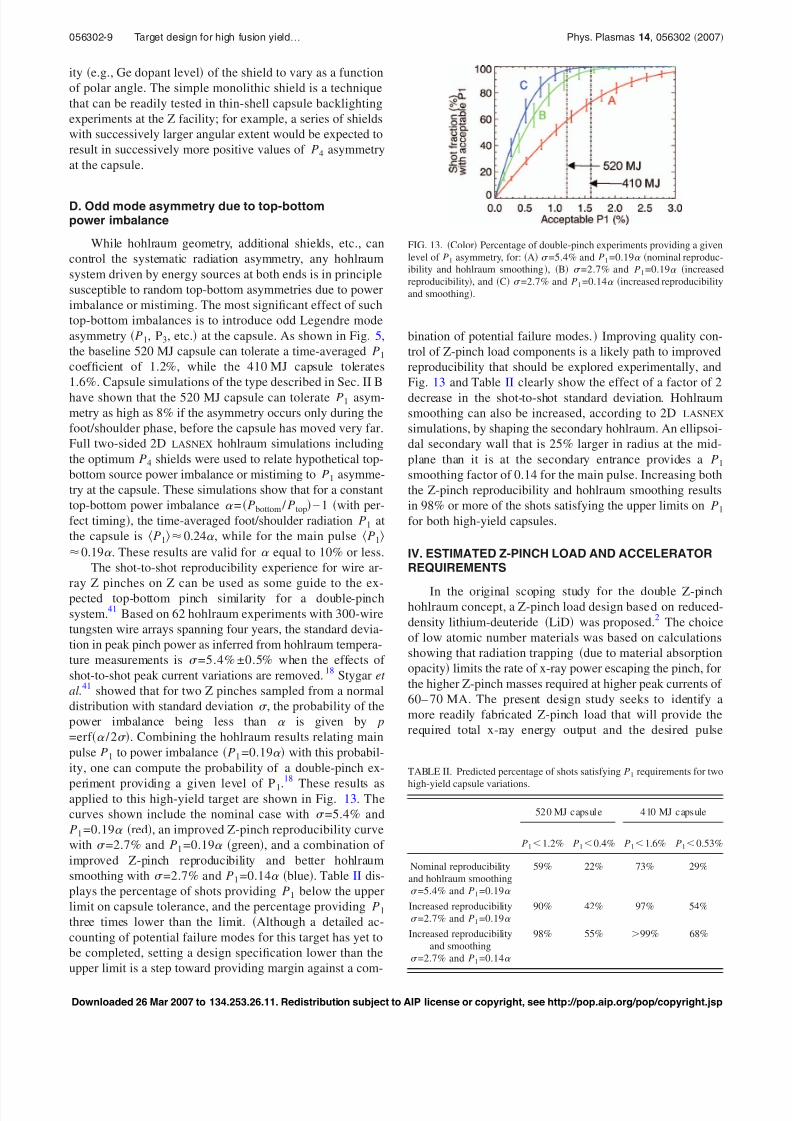
These results asapplied to this high-yield target are shown in Fig. 13. The
curves shown include the nominal case with =5.4% and
P1 =0.19 red, an improved Z-pinch reproducibility curve
with =2.7% and P1 =0.19 green, and a combination of
improved Z-pinch reproducibility and better hohlraum
smoothing with =2.7% and P1 =0.14 blue. Table II dis-
plays the percentage of shots providing P1 below the upper
limit on capsule tolerance, and the percentage providing P1
three times lower than the limit. Although a detailed ac-
counting of potential failure modes for this target has yet to
be completed, setting a design specification lower than the
upper limit is a step toward providing margin against a com-
bination of potential failure modes. Improving quality con-
trol of Z-pinch load components is a likely path to improved
reproducibility that should be explored experimentally, and
Fig. 13 and Table II clearly show the effect of a factor of 2
decrease in the shot-to-shot standard deviation. Hohlraum
smoothing can also be increased, according to 2D LASNEX
simulations, by shaping the secondary hohlraum. An ellipsoi-
dal secondary wall that is 25% larger in radius at the mid-
plane than it is at the secondary entrance provides a P1
smoothing factor of 0.14 for the main pulse. Increasing both
the Z-pinch reproducibility and hohlraum smoothing results
in 98% or more of the shots satisfying the upper limits on P1
for both high-yield capsules.
IV. ESTIMATED Z-PINCH LOAD AND ACCELERATORREQUIREMENTS
In the original scoping study for the double Z-pinchhohlraum concept, a Z-pinch load design based on reduced-
density lithium-deuteride LiD was proposed.2
The choice
of low atomic number materials was based on calculations
showing that radiation trapping due to material absorption
opacity limits the rate of x-ray power escaping the pinch, for
the higher Z-pinch masses required at higher peak currents of
60– 70 MA. The present design study seeks to identify a
more readily fabricated Z-pinch load that will provide the
required total x-ray energy output and the desired pulse
FIG. 13. Color Percentage of double-pinch experiments providing a given
level of P1 asymmetry, for: A =5.4% and P1 =0.19 nominal reproduc-
ibility and hohlraum smoothing, B =2.7% and P1 =0.19 increased
reproducibility, and C =2.7% and P1 =0.14 increased reproducibility
and smoothing.
TABLE II. Predicted percentage of shots satisfying P1 requirements for two
high-yield capsule variations.
520 MJ capsul e 410 MJ capsule
P11.2% P10.4% P11.6% P10.53%
Nominal reproducibility
and hohlraum smoothing
=5.4% and P1 =0.19
59% 22% 73% 29%
Increased reproducibility
=2.7% and P1 =0.19
90% 42% 97% 54%
Increased reproducibility
and smoothing
=2.7% and P1 =0.14
98% 55% 99% 68%
056302-9 Target design for high fusion yield… Phys. Plasmas 14, 056302 2007
Downloaded 26 Mar 2007 to 134.253.26.11. Redistribution subject to AIP license or copyright, see http://pop.aip.org/pop/copyright.jsp
8/3/2019 R. A. Vesey et al- Target design for high fusion yield with the double Z-pinch-driven hohlraum
http://slidepdf.com/reader/full/r-a-vesey-et-al-target-design-for-high-fusion-yield-with-the-double-z-pinch-driven 10/13
shape. In addition, although it is not clear whether the best
Z-pinch performance at higher currents will be provided by
wire arrays or by continuous liners, Z-pinch modeling must
begin to consider the implications for both options. Although
work is still in progress to design a Z-pinch load that satisfies
the x-ray output requirements plotted in Fig. 7, a number of
physics conclusions can be made here. First, the ongoing
simulations confirm the importance of Z-pinch material
opacity in trapping x rays and limiting the efficiency with
which electrical energy is converted to useful x-ray energy.
As a result, present Z-pinch load designs are based on beryl-
lium components. Unlike the LiD used in the initial scoping
study, beryllium is readily fabricated in the form of liners or
wire arrays, and the conductivity properties of beryllium are
expected to allow azimuthally uniform initiation of the cur-
rent in the load. Quantum molecular dynamics-based wide-
range conductivity tables
42
are now available for beryllium,needed to model the range of expected conditions from room
temperature solid to high temperature plasma.
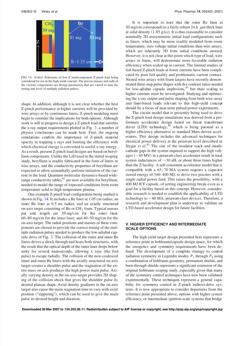
One example Z-pinch load configuration being studied is
shown in Fig. 14. It includes a Be liner at 1.05 cm radius, an
inner Be liner at 0.5 cm radius, and an axially structured
on-axis target consisting of Be or CH2 foam. Typical masses
per unit length are 30 mg/cm for the outer liner,
60–80 mg/cm for the inner liner, and 40–50 mg/cm for the
on-axis target. The radial positions and masses of these com-
ponents are chosen to provide the correct timing of the mul-
tiple radiation pulses needed to produce the low-adiabat cap-
sule drive of Fig. 3. The collision of the outer and inner Be
liners drives a shock through and heats both structures, withthe result that the optical depth of the outer liner drops below
unity for several nanoseconds, allowing x rays the foot
pulse to escape radially. The collision of the now-coalesced
inner and outer Be liners with the axially structured on-axis
target creates a shoulder pulse and the stagnation of the en-
tire mass on axis produces the high power main pulse. Axi-
ally varying density in the on-axis target provides 2D shap-
ing of the collision shock that gives the shoulder pulse its
desired plateau shape. Axial density gradients in the on-axis
target also cause the main stagnation time to vary with axial
position “zippering”, which can be used to give the main
pulse its desired height and duration.
It is important to note that the outer Be liner at
30 mg/cm corresponds to a fairly robust 24.6 m thick liner
at solid density 1.85 g/cc. It is thus reasonable to consider
nominally 2D axisymmetric initial load configurations such
as liners, which may be more readily modeled from room
temperature, zero voltage initial conditions than wire arrays,
which are inherently 3D from initial conditions onward.
However, it is not clear at this point which type of load, wire
arrays or liners, will demonstrate more favorable radiationefficiency when scaled up in current. The limited studies of
foil-based Z-pinch loads at lower currents have been compli-
cated by poor foil quality and problematic current contact.
Nested wire arrays with foam targets have recently demon-
strated three-step pulse shapes with the contrast ratios needed
for low-adiabat capsule implosions,43
but their scaling to
higher currents must be investigated. Studying and optimiz-
ing the x-ray output and pulse shaping from both wire-array
and liner-based loads relevant to this high-yield concept
should be a focus of near-term pulsed-power experiments.
The circuit model that is presently being used to drive
the Z-pinch load design simulations was derived from a pre-
liminary accelerator design based on linear transformerdriver LTD technology,
44which is being pursued as a
higher efficiency alternative to standard Marx-driven accel-
erators. This design includes the advanced techniques for
electrical power delivery at the petawatt level described in
Stygar et al.45
The size of the insulator stack and anode-
cathode gaps in the system required to support the high volt-
ages 30 MV in a petawatt-class accelerator result in total
system inductances of 30 nH, or about three times higher
than the Z facility. A self-consistent accelerator model that is
compatible with a 65– 70 MA system requires a capacitor
stored energy of 340–400 MJ, to drive two pinches with a
single radial power feed. This raises the possibility, with a
400 MJ ICF capsule, of setting engineering break-even as a
goal for a facility based on this concept. However, consider-
able research is needed to establish the applicability of LTD
technology to 60 MA, petawatt-class devices. Therefore, a
research and development plan is underway to validate an
LTD-based accelerator design for future facilities.
V. HIGHER EFFICIENCY AND INTERMEDIATESCALE OPTIONS
The high-yield target design presented here represents a
reference point in hohlraum/capsule design space, for whichthe energetics and symmetry requirements have been de-
fined. The development of a complete strategy to control
radiation symmetry in Legendre modes P1 through P8 using
a combination of hohlraum geometry, permanent shields, and
burn-through shields represents a significant extension of the
original hohlraum scoping study, especially given that many
of the symmetry control techniques have now been validated
experimentally. These techniques represent a general capa-
bility for symmetry control in Z-pinch indirect-drive sys-
tems. It is now appropriate to consider departures from the
reference point presented above, options with higher system
efficiency, or intermediate ignition-scale systems that bridge
FIG. 14. Color Schematic of low-Z multicomponent Z-pinch load being
considered for use in the high-yield concept. The precise masses and radii of
the various components are design parameters that are varied to tune the
timing and level of multiple radiation pulses.
056302-10 Vesey et al. Phys. Plasmas 14, 056302 2007
Downloaded 26 Mar 2007 to 134.253.26.11. Redistribution subject to AIP license or copyright, see http://pop.aip.org/pop/copyright.jsp
8/3/2019 R. A. Vesey et al- Target design for high fusion yield with the double Z-pinch-driven hohlraum
http://slidepdf.com/reader/full/r-a-vesey-et-al-target-design-for-high-fusion-yield-with-the-double-z-pinch-driven 11/13
the gap from present-day accelerators to the high-yield
concept.
One option under consideration is to drive the two Z
pinches in series, as has been done in all double Z-pinch
experiments on Z to date.6,18
In Z experiments, a
magnetically-insulated transmission line MITL feeding
power to the load attaches to the bottom of the Z-pinch
load/hohlraum assembly. This means that the primary hohl-
raum geometry is asymmetric across the midplane the plane
cutting through the center of the capsule, which implies that
even with perfectly balanced top-bottom pinch power, the P1
asymmetry will be nonzero. Alternatively, a single MITL at-
tached as a radial disk feed to the Z-pinch load/hohlraum
assembly at the midplane, shown schematically in Fig. 15,
restores a top-bottom symmetric hohlraum geometry. A
single MITL simplifies the accelerator design. Furthermore, a
single MITL feed requires 30% less stored energy to drive
the same peak current than an accelerator driving two sepa-
rate Z pinches via two separate MITLs.45
LASNEX simula-
tions with the midplane power feed geometry give 2D cap-sule performance similar to that calculated with the two-
sided power feed with the same assumed source x-ray power
and current. Low levels of asymmetry and a 2D yield of
460 MJ are obtained for the midplane feed configuration;
thus this option has a higher efficiency from the standpoint
of capsule absorbed energy and yield relative to the stored
energy. Questions about the effect of differing radial electric
field, above and below the midplane, on the early ablation
and implosions of the two Z-pinch loads,46
must be ad-
dressed experimentally and theoretically for this
configuration.
The hohlraum energetics relationships for the double
Z-pinch hohlraum2,7
imply that the energy and power neces-sary to heat the hohlraum to a given temperature scale
strongly with the size of the hohlraum. It is also important to
note that because the largest sinks of energy are the primary
hohlraum walls, and because the x-ray energy enters the sec-
ondary hohlraum through an aperture that is essentially the
size of the secondary hohlraum, simply decreasing the size
of the secondary hohlraum does not increase the drive tem-
perature experienced by the capsule. Dramatic increases in
the radiation temperature for a given source power and en-
ergy are possible if one can reduce the size of the primary
hohlraum. A scaling study using 2D LASNEX quantified the
relationship of primary hohlraum temperature to primary
hohlraum radius, Z-pinch peak power, and rise time of the
power for Gaussian power pulses,47
and a numerical fit to the
results was found. For a fixed pinch power rise time, the
peak pinch power required to attain a given peak hohlraum
re-emission temperature is given approximately by
P R p2 + R p L p1.1, 3
where R p is the primary hohlraum radius and L p is the pri-
mary hohlraum length. For the nominal hohlraum sizes con-
sidered in this paper, with a peak capsule drive temperature
of 220 eV, the peak primary hohlraum re-emission tempera-
ture is 240 eV. For example, to attain the same 240 eV
peak temperature in a primary with R p =0.8 cm rather than
the nominal 1.25 cm, expression 3 implies that the Z-pinch
power and energy could be scaled down by a factor of 0.48.
This option must be more precisely defined in simulations
but would represent a significant increase in system effi-
ciency as defined by the ratio of the capsule absorbed energy
to the stored energy. While hohlraum size strongly influences
the energetics requirements, incremental increases in hohl-
raum efficiency can be realized with further optimization of
mixed-component hohlraum walls,48
slightly shorter Z-pinch
loads and primary hohlraums, optimizing the spoke transmis-
sion, or allowing some radiation burn-through of the on-axis
shine shields.47
The hohlraum size energetics scaling can be extended to
other temperatures assuming P T r 3.3,
7seeking intermediate-
scale, higher temperature hohlraum systems that achieve ig-
nition at the 50 MJ level. For example, a Scale 0.6 hohl-
raum intended to drive a 1.6 mm radius capsule with a
shorter pulse peaking at 250 eV, with a primary hohlraumradius of 0.75 cm and length of 0.6 cm and an initial Z-pinch
load radius of 0.6 cm, is estimated to require a peak primary
hohlraum temperature of 270 eV and therefore a peak pinch
power of 465 TW per side using expression 3. Using the
more general energetics scaling that includes the effect of the
shorter rise time for the more compact system, the result is
525 TW per side. LASNEX hohlraum simulations of such a
system including the secondary entrance foams and P4
shields discussed in Sec. III C demonstrate that a shaped
temperature pulse peaking at 250 eV can indeed be achieved
with a peak power of 550 TW per pinch and a total useful
x-ray energy of 3.0 MJ per pinch, delivering 0.4 MJ to the
capsule. Such a temperature pulse is compatible with higherimplosion velocity, lower yield capsules. A number of ideas
for generating high x-ray power from compact sources have
been proposed and tested on 1 MA class machines, and their
performance must be tested at the 20 MA level and above.
These include planar wire arrays,49
radial wire arrays,50
X
pinches,49
and short implosion time compact single51
and
nested wire arrays52
the latter two having undergone pre-
liminary tests at 20 MA on Z. As x-ray sources and primary
hohlraums can be made more compact, secondary entrance
tamping, hohlraum wall tamping, and mode-selective sym-
metry control techniques will become even more important
to provide adequate energy coupling and symmetry control.
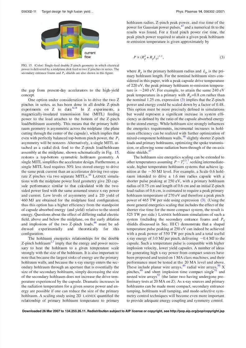
FIG. 15. Color Single-feed double Z-pinch geometry in which electrical
power is delivered by a midplane disk feed to two Z pinches in series. The
secondary entrance foams and P4 shields are also shown in this figure.
056302-11 Target design for high fusion yield… Phys. Plasmas 14, 056302 2007
Downloaded 26 Mar 2007 to 134.253.26.11. Redistribution subject to AIP license or copyright, see http://pop.aip.org/pop/copyright.jsp
8/3/2019 R. A. Vesey et al- Target design for high fusion yield with the double Z-pinch-driven hohlraum
http://slidepdf.com/reader/full/r-a-vesey-et-al-target-design-for-high-fusion-yield-with-the-double-z-pinch-driven 12/13
VI. CONCLUSIONS
The initial scoping study of the double Z-pinch hohl-
raum inertial fusion concept has been revisited with particu-
lar attention to capsule robustness, hohlraum symmetry con-
trol, and Z-pinch pulse shaping. Capsules with 1D yields of
400–500 MJ are insensitive to relatively large variations in
the three-step temperature pulse timing and level, show tol-
erance of surface roughness at levels well above that achiev-able with today’s fabrication technology, and tolerate radia-
tion asymmetry levels that are attainable with hohlraum
symmetry control techniques. Fine tuning of the time-
dependent radiation symmetry has been demonstrated for the
first time in simulations using small-angular-range shields
that specifically tune the P4 asymmetry without perturbing
the P6, P8, or higher modes. Maintaining low levels of asym-
metry has enabled the demonstration of robust ignition and
burn of the capsule in 2D integrated hohlraum+capsule
simulations yielding 470 MJ. The capsule and hohlraum en-
ergetics results determine the goal of the Z-pinch load design
research, which is ongoing: the generation of a 9 MJ x-ray
pulse properly shaped with a 0.5 MJ foot pulse generated
15–20 ns prior to peak power. Several Z-pinch load varia-
tions are currently being pursued in simulations to generate
the required pulse. Looking ahead, improvements in the
overall system efficiency look promising using variations on
the reference design such as a midplane feed-driven system
to improve the accelerator/Z-pinch efficiency, as well as
compact x-ray sources and compact primary hohlraums
which may allow ignition-class experiments to be conducted
with stored energies higher than present accelerators but
lower than the high-yield concept.
ACKNOWLEDGMENTS
We would like to thank Dr. Debra Callahan, Dr. Jim
Hammer, Dr. Judy Harte, Dr. John Lindl, Dr. Steve
MacLaren, and Dr. George Zimmerman LLNL for valuable
discussions on the LASNEX simulations, as well as Mark
Johnston Ktech, SNL and Lee Busby LLNL for LASNEX
computing support. We also acknowledge the enthusiastic
programmatic support of Dr. Keith Matzen.
Sandia is a multiprogram laboratory operated by Sandia
Corporation, a Lockheed Martin Company, for the United
States Department of Energy’s National Nuclear Security
Administration under Contract No. DE-AC04-94AL85000.1
T. W. L. Sanford, G. O. Allshouse, B. M. Marder et al., Phys. Rev. Lett.
77, 5063 1996; C. Deeney, T. J. Nash, R. B. Spielman et al., Phys. Rev.
E 56, 5945 1997.2
J. H. Hammer, M. Tabak, S. C. Wilks, J. D. Lindl, D. S. Bailey, P. W.
Rambo, A. Toor, G. B. Zimmerman, and J. L. Porter, Jr., Phys. Plasmas 6,
2129 1999.3
R. B. Spielman, C. Deeney, G. A. Chandler et al., Phys. Plasmas 5, 2105
1998.4
J. L. Porter, Jr., Bull. Am. Phys. Soc. 42, 1948 1997; K. L. Baker, J. L.
Porter, L. E. Ruggles et al., Appl. Phys. Lett. 75, 775 1999.5
M. E. Cuneo, R. A. Vesey, J. L. Porter, Jr. et al., Bull. Am. Phys. Soc. 44,
40 1999.6
M. E. Cuneo, R. A. Vesey, J. L. Porter, Jr. et al., Phys. Plasmas 8, 2257
2001.
7M. E. Cuneo, R. A. Vesey, J. H. Hammer, J. L. Porter, Jr., L. E. Ruggles,
and W. W. Simpson, Laser Part. Beams 19, 481 2001.8
R. A. Vesey and T. A. Mehlhorn, Bull. Am. Phys. Soc. 43, 1903 1998;
R. A. Vesey, M. Cuneo, D. Hanson, J. Porter, T. Mehlhorn, L. Ruggles, W.
Simpson, M. Vargas, J. Hammer, and O. Landen, ibid. 44, 227 1999; R.
A. Vesey, M. E. Cuneo, D. L. Hanson, J. L. Porter, Jr., T. A. Mehlhorn, L.
E. Ruggles, W. W. Simpson, J. H. Hammer, and O. Landen, ibid. 45, 360
2000.9
R. A. Vesey, D. L. Hanson, M. E. Cuneo, G. R. Bennett, J. L. Porter, T. A.
Mehlhorn, J. H. Hammer, R. G. Adams, L. E. Ruggles, and W. W. Simp-
son, in Inertial Fusion Sciences and Applications 2001, edited by K. A.Tanaka, D. D. Meyerhofer, and J. Meyer-ter-Vehn Elsevier, Paris, 2002,
p. 681.10
M. E. Cuneo, R. A. Vesey, J. L. Porter, Jr. et al., Phys. Rev. Lett. 88,
215004 2002.11
G. R. Bennett, O. L. Landen, R. F. Adams, J. L. Porter, L. E. Ruggles, W.
W. Simpson, and C. Wakefield, Rev. Sci. Instrum. 72, 657 2001.12
G. R. Bennett, M. E. Cuneo, R. A. Vesey et al., Phys. Rev. Lett. 89,
245002 2002.13
D. B. Sinars, M. E. Cuneo, G. R. Bennett et al., Rev. Sci. Instrum. 74,
2202 2003.14
R. A. Vesey, M. E. Cuneo, G. R. Bennett et al., Phys. Rev. Lett. 90,
035005 2003.15
R. A. Vesey, M. E. Cuneo, J. L. Porter, Jr. et al., Phys. Plasmas 10, 1854
2003.16
R. A. Vesey, M. E. Cuneo, G. R. Bennett, J. L. Porter, and T. A. Mehlhorn,
Bull. Am. Phys. Soc. 50, 123 2005.17R. A. Vesey, M. E. Cuneo, G. R. Bennett, J. L. Porter, and T. A. Mehlhorn,
J. Phys. IV 133, 1167 2006.18
M. E. Cuneo, R. A. Vesey, G. R. Bennett et al., Plasma Phys. Controlled
Fusion 48, R1 2006.19
G. B. Zimmerman and W. L. Kruer, Comments Plasma Phys. Controlled
Fusion 2, 51 1975.20
S. W. Haan personal communication.21
M. C. Herrmann, M. Tabak, and J. D. Lindl, Nucl. Fusion 41, 99 2001;
D. H. Munro, P. M. Celliers, G. W. Collins, D. M. Gold, L. B. DaSilva, S.
W. Haan, R. C. Cauble, B. A. Hammel, and W. W. Hsing, Phys. Plasmas
8, 2245 2001.22
W. J. Krauser, N. M. Hoffman, D. C. Wilson et al., Phys. Plasmas 3, 2084
1996.23
T. R. Dittrich, S. W. Haan, M. M. Marinak, S. M. Pollaine, and R.
McEachern, Phys. Plasmas 5, 3708 1998.24
M. M. Marinak, G. D. Kerbel, N. A. Gentile, O. Jones, D. Munro, S.Pollaine, T. R. Dittrich, and S. W. Haan, Phys. Plasmas 8, 2275 2001.
25T. R. Dittrich, S. W. Haan, M. M. Marinak et al., Phys. Plasmas 6, 2164
1999.26
R. M. More, K. H. Warren, D. A. Young, and G. B. Zimmerman, Phys.
Fluids 31, 3059 1988.27
See National Technical Information Service Document DE-96004569 M.
M. Marinak, R. E. Tipton, B. A. Remington, S. W. Haan, and S. V. Weber,
in ICF Quarterly Report, UCRL-LR-105821-95-3, 1995. Copies may be
ordered from National Technical Information Service, Springfield, VA
22161.28
The NIF standard spectrum mode coefficients in nm are expressed as
Rlm =10/ l1.5 +0.08/ l /600.7 + l /12004 for the mode range typically
used in multimode calculations. As used in the 2D axisymmetric simula-
tions, each l mode contains the perturbation power of the 21+ l azimuthal
m modes.29
S. W. Haan, M. C. Herrmann, T. R. Dittrich, A. J. Fetterman, M. M.Marinak, D. H. Munro, S. M. Pollaine, J. D. Salmonson, G. L. Strobel, and
L. J. Suter, Phys. Plasmas 12, 056316 2005.30
A. Nikroo, K. C. Chen, M. L. Hoppe et al., Phys. Plasmas 13, 056302
2006.31
S. Pollaine, P. Amendt, S. Haan, M. Herrmann, O. Jones, and L. Suter, in
Inertial Fusion Sciences and Applications 2003, edited by B. A. Hammel,
D. D. Meyerhofer, J. Meyer-ter-Vehn, and H. Azechi ANS, La Grange
Park, IL, 2004, p. 104.32
T. J. Orzechowski, M. D. Rosen, H. N. Kornblum, J. L. Porter, L. J. Suter,
A. R. Thiessen, and R. J. Wallace, Phys. Rev. Lett. 77, 3545 1996.33
S. W. Haan, S. M. Pollaine, J. D. Lindl et al., Phys. Plasmas 2, 2480
1995; M. Tabak and D. Callahan-Miller, ibid. 5, 1895 1998.34
M. E. Cuneo, E. M. Waisman, S. V. Lebedev et al., Phys. Rev. E 71,
046406 2005.35
A. Caruso and C. Strangio, Jpn. J. Appl. Phys., Part 1 30, 1095 1991.
056302-12 Vesey et al. Phys. Plasmas 14, 056302 2007
Downloaded 26 Mar 2007 to 134.253.26.11. Redistribution subject to AIP license or copyright, see http://pop.aip.org/pop/copyright.jsp
8/3/2019 R. A. Vesey et al- Target design for high fusion yield with the double Z-pinch-driven hohlraum
http://slidepdf.com/reader/full/r-a-vesey-et-al-target-design-for-high-fusion-yield-with-the-double-z-pinch-driven 13/13
36M. E. Cuneo, G. R. Bennett, R. A. Vesey et al., Bull. Am. Phys. Soc. 48,
207 2003.37
G. R. Bennett, M. E. Cuneo, R. A. Vesey et al., Bull. Am. Phys. Soc. 48,
207 2003.38
See National Technical Information Services Document No. DE95011970
T. J. Murphy and P. A. Amendt, ICF Quarterly Report Vol. 4, pp. 101,
1994, Lawrence Livermore National Laboratory, UCRL-LR-105821-94-
3, copies may be ordered from National Technical Information Service,
Springfield, VA 22161; D. D.-M. Ho, J. A. Harte, and M. Tabak, Nucl.
Fusion 35, 1125 1995; D. L. Hanson, R. A. Vesey, M. E. Cuneo et al.,
Phys. Plasmas9
, 2173 2002.39D. A. Callahan, M. C. Herrmann, and M. Tabak, Laser Part. Beams 20,
405 2002; D. A. Callahan, M. Tabak, G. R. Bennett, M. E. Cuneo, R. A.
Vesey, A. Nikroo, D. Czechowicz, and D. Steinman, Plasma Phys. Con-
trolled Fusion 47, B379 2005.40
Spoke array simulations more recent than those mentioned in Refs. 2 and
6 indicate that low-density foam in the secondary entrance also tamps the
expansion and axial flow of ablated spoke plasma, leading to possibly
more ideal spoke behavior. There is also experimental experience with
secondary tamping foams. Recent Z experiments on hohlraum coupling
and capsule symmetry, which have been used to validate 2D hohlraum
simulations, included a combination of radial spoke arrays and low-
density foams at the secondary entrance. X-ray transmission values of
67±5% were measured for this configuration Ref. 18, consistent with the
71±7% inferred for cases without foam.41
W. A. Stygar, H. C. Ives, D. L. Fehl et al., Phys. Rev. E 69, 046403
2004.42M. P. Desjarlais, J. D. Kress, and L. A. Collins, Phys. Rev. E 66, 025401
2002.
43M. E. Cuneo, R. A. Vesey, D. B. Sinars et al., Phys. Rev. Lett. 95, 185001
2005.44
M. G. Mazarakis, R. B. Spielman, K. W. Struve, and F. W. Long, in
Proceedings of the 13th IEEE International Pulse Power Conference, ed-
ited by R. Reinovsky and M. Newtonon IEEE, Piscataway, NJ, 2001, p.
587; M. G. Mazarakis, W. E. Fowler, F. W. Long, D. H. McDaniel, C. L.
Olson, S. T. Rogowski, R. A. Sharpe, and K. W. Struve, in Proceedings of
the 15th IEEE International Pulse Power Conference IEEE, Piscataway,
NJ, 2005.45
W. A. Stygar, M. E. Cuneo, R. A. Vesey et al., Phys. Rev. E 72, 026404
2005; W. A. Stygar, M. E. Cuneo, D. I. Headley, H. C. Ives, R. J. Leeper,M. G. Mazarakis, C. L. Olson, J. L. Porter, and T. C. Wagoner, “Archi-
tecture of petawatt-class Z-pinch accelerators,” Phys. Rev. ST Accel.
Beams to be published.46
S. N. Bland, S. V. Lebedev, J. P. Chittenden et al., Phys. Rev. Lett. 95,
135001 2005.47
R. A. Vesey, M. E. Cuneo, G. R. Bennett, J. L. Porter, and T. A. Mehlhorn,
Bull. Am. Phys. Soc. 49, 279 2004.48
L. J. Suter, J. Rothenburg, D. Munro, B. Van Wonterghem, and S. Haan,
Phys. Plasmas 7, 2092 2000.49
V. L. Kantsyrev, A. S. Safronova, D. A. Fedin et al., IEEE Trans. Plasma
Sci. 34, 194 2006.50
S. V. Lebedev, A. Ciardi, D. J. Ampleford et al., Plasma Phys. Controlled
Fusion 47, B465 2005; S. N. Bland, Bull. Am. Phys. Soc. 51, 338
2006.51
D. B. Sinars personal communication.52
M. E. Cuneo, D. B. Sinars, E. M. Waisman et al., Phys. Plasmas 13,
056318 2006.
056302-13 Target design for high fusion yield… Phys. Plasmas 14, 056302 2007